Turbomachinery Simulation using STAR-CCM+
41
Turbomachinery Simulation using STAR-CCM+
Transcript of Turbomachinery Simulation using STAR-CCM+

Turbomachinery Simulation
using STAR-CCM+

Usage From Across the Industry

• Key Objectives
– Conjugate heat transfer
– Aeroelastic response
– Performance mapping
• Key Capabilities
– Complex geometry handling
– Conformal polyhedral meshing
– Harmonic balance
– Advanced post-processing
• Best Practice
– Mesh requirements
– Solution procedure
Outline

Key Capabilities
• Direct CAD import
• 3D CAD editing
• Meshing
– Polyhedral cells
– Conformal interfaces
– Automatic prism layer generation
Conjugate Heat Transfer

Key Capabilities
• Direct CAD import
Cooled Turbine Blade
Direct import of CAD
solid geometry

Key Capabilities
• 3D CAD editing
Cooled Turbine Blade
External and cooling air
volumes generated
using 3D CAD

Key Capabilities
• Meshing
– Automatic mesh generation
Cooled Turbine Blade
• Pipelined meshing
• Simple global size settings
• Local refinement control
• Automatic solution interpolation

Key Capabilities
• Meshing
– Automatic mesh generation
– Polyhedral cells
Cooled Turbine Blade
Fewer cells required

Key Capabilities
• Meshing
– Automatic mesh generation
– Polyhedral cells
Cooled Turbine Blade
Good for swirling flow
Polyhedral cell faces are orthogonal to the flow regardless
of flow direction

Key Capabilities
• Meshing
– Automatic mesh generation
– Polyhedral cells
Cooled Turbine Blade
High quality cells, even
with complex geometry


Key Capabilities
• Meshing
– Automatic mesh generation
– Polyhedral cells
– Conformal interfaces
– Automatic prism layer generation
Cooled Turbine Blade
Cells are one-to-one
connected on the
solid/fluid interface
Fluid-side prism layers are
automatically generated

Traditional simulation methods present many challenges
• Aeroelastic analysis must be run unsteady
• Traditional unsteady simulation is challenging
– Very long run times
– Must mesh the entire machine
– Hard to specify blade vibration
– Hard to extract stability information
Aeroelastic Response
• Harmonic balance method in STAR-CCM+
resolves each of these challenges
• The HB method is not available in any other
commercial package

• The harmonic balance method takes advantage of the periodic
nature of a turbomachine
• Solves a set of equations that converge to the periodic,
unsteady solution
• Full non-linear solver
• All unsteady interactions captured
Harmonic Balance Basics

Rapid calculation of unsteady solution
• Unsteady simulation must be run for many time steps to
converge
• HB simulation converges to the unsteady solution 10x faster
Harmonic Balance Key Benefits
Red: Time Domain
Blue: Harmonic Balance

Single blade passage mesh
• All blades must be meshed for an unsteady simulation
• Only one blade passage must be meshed for a HB simulation,
however the solution is calculated for all blades
Harmonic Balance Key Benefits
Time Domain
Harmonic Balance

Specify blade vibration
– The vibration of each blade is
staggered. This is known as the
“Interblade phase angle”
– To determine stability a simulation
must be run for each phase angle
– Traditional unsteady solvers require
manual set up of motion for each
phase angle
Harmonic Balance Key Benefits

Specify blade vibration
Interblade phase angle is a simple input to the HB solver
Harmonic Balance Key Benefits

Work per cycle calculation
– Stability is determined by “Work per cycle”
– Traditional unsteady solver requires the solution
be saved at each time step and complex, external
post processing to determine this value
Work per cycle is a simple report when using the
HB solver
Harmonic Balance Key Benefits

Example: Vane Flutter
Unsteady Pressure (Pa)
Motion

• Work per cycle map shows this vane will not flutter
Example: Vane Flutter

Key Benefits
• Complex geometry handling
• Polyhedral cells
• High quality mesh
• Prism layer generation
• Harmonic balance solver
Performance Mapping

Key Benefits
• Grid sequencing initialization
• Efficiency optimization with Optimate+
• Turbomachinery specific post-processing
Performance Mapping
Already discussed

Key Benefits
• Grid sequencing initialization
Performance Mapping
• Drastically reduce run time
• Reduce need for ramping
• Increased simulation
robustness
Initialization Converged Solution
Time to initialization:
80 seconds

Key Benefits
• Efficiency optimization with Optimate+
Performance Mapping

Key Benefits
• Turbomachinery specific post-processing
Performance Mapping
Blade-to-blade
projection

Key Benefits
• Turbomachinery specific post-processing
Performance Mapping
Meridional
projection

Key Benefits
• Turbomachinery specific post-processing
Performance Mapping
Circumferential
Averaging

1
1.2
1.4
1.6
1.8
2
2.2
2.4
2.6
2.8
3
3.2
3.4
3.6
3.8
4
0 0.02 0.04 0.06 0.08 0.1 0.12 0.14 0.16 0.18 0.2
Pre
ss
ure
Ra
tio
(t/t)
P2
c/P
1c
Corrected Air Flow (Kg/s)• •
•
•••
•
• Comparison with rig measurements
– Full performance curve
– RPM range
Validated Simulation: Radial Compressor

190000 RPM
210000 RPM
0.6
0.65
0.68 0.7
0.72
0.74 0.75
1
1.2
1.4
1.6
1.8
2
2.2
2.4
2.6
2.8
3
3.2
3.4
3.6
3.8
4
0 0.02 0.04 0.06 0.08 0.1 0.12 0.14 0.16 0.18 0.2
• Installation effects
– Curved inlet duct
– Diffuser outlet
Validated Simulation: Radial Compressor

• Polyhedral mesh with extruded inlet/exit as needed
Turbomachinery Meshing Guidelines

• High resolution of leading and trailing edges
Turbomachinery Meshing Guidelines

• Uniform cell sizing in the primary gas path
Turbomachinery Meshing Guidelines

• All y+ algorithm with y+ values less than 5
Turbomachinery Meshing Guidelines

• Last prism layer similar size to the first poly cell layer
Turbomachinery Meshing Guidelines
Polyhedral Cells
Prism Layer Cells
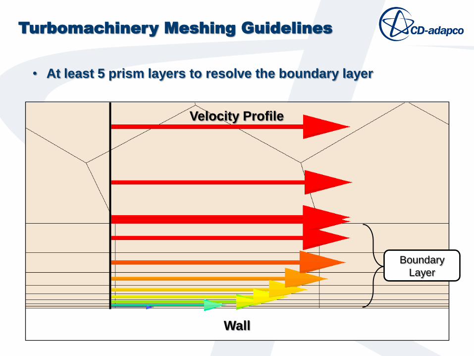
• At least 5 prism layers to resolve the boundary layer
Turbomachinery Meshing Guidelines
Wall
Velocity Profile
Boundary
Layer

Reference Values
• Set reference pressure to be near the
operating point
Initial Conditions
• Set velocity to a non-zero value
• Set initial pressure to the inlet or exit value,
whichever is greater
• Set temperature the inlet value
Turbomachinery Solution Guidelines

Initialization
• Use grid sequencing initialization to obtain
an initial condition
• Ensure that each grid level converges
• Initialize solution using actual operating
conditions (do not ramp boundary
conditions or rotation rate)
Suggested GSI parameters
• Max iterations per level: 200
• Convergence tolerance: 0.005
• CFL number: 20
Turbomachinery Solution Guidelines

Solver Settings
• Use a high CFL number whenever possible,
a CFL number of 20 is a good starting point
• For cases with high and low speed flow
regions, enable Continuity Convergence
Acceleration
Turbomachinery Solution Guidelines

• Key Objectives
– Conjugate heat transfer
– Aeroelastic response
– Performance mapping
• Key Capabilities
– Complex geometry handling
– Conformal polyhedral meshing
– Harmonic balance
– Advanced post-processing
• Best Practice
– Mesh requirements
– Solution procedure
Overview