Turbomachinery 1
26
8. HYDRAULIC PUMPS Pumps are devices that transfer energy from an external source to a liquid in order to move the liquid from one location to another. This process will increase the energy of the liquid after it leaves the pump. The hydraulic characteristics of a specific piping system (simply referred to the system) as well as the physical and chemical characteristics of the liquid itself would determine what type of pump is most suitable for one specific application. These characteristics include liquid viscosity, specific weight, working temperature, corrosion property, possibly dissolved gases and suspended particles in the liquid. All of these elements along with the volume of the liquid that has to be pumped per unit of time and the required pressure have led to development of pumps with different structures, designs, and applications. The mechanisms of energy transfer between pumps and the liquids are so different that it is impossible to utilize a unique theory to describe the process. For this reason, pumps are divided into different categories and each category is then defined and analyzed. In the following sections the classification of pumps in general and the description of turbopumps in particular are presented. To show the reader the difference between each type, a picture of each pump has been shown to illustrate the major differences. 8.1. Pump Classification The classification of pumps is done based on different criteria. This classification could be based on the application, internal structure, the mechanism of energy transfer between pump and liquid, or based on the type of pumped liquid. The most common way of classification is, however, based on the mechanism of energy transfer. In this respect, pumps are divided into two major categories:
-
Upload
jason-ross -
Category
Documents
-
view
99 -
download
2
description
Turbomachinery
Transcript of Turbomachinery 1

8. HYDRAULIC PUMPS
Pumps are devices that transfer energy from an external source to a liquid in order to move the liquid from one location to another. This process will increase the energy of the liquid after it leaves the pump.
The hydraulic characteristics of a specific piping system (simply referred to the system) as well as the physical and chemical characteristics of the liquid itself would determine what type of pump is most suitable for one specific application. These characteristics include liquid viscosity, specific weight, working temperature, corrosion property, possibly dissolved gases and suspended particles in the liquid. All of these elements along with the volume of the liquid that has to be pumped per unit of time and the required pressure have led to development of pumps with different structures, designs, and applications.
The mechanisms of energy transfer between pumps and the liquids are so different that it is impossible to utilize a unique theory to describe the process. For this reason, pumps are divided into different categories and each category is then defined and analyzed. In the following sections the classification of pumps in general and the description of turbopumps in particular are presented. To show the reader the difference between each type, a picture of each pump has been shown to illustrate the major differences.
8.1. Pump Classification
The classification of pumps is done based on different criteria. This classification could be based on the application, internal structure, the mechanism of energy transfer between pump and liquid, or based on the type of pumped liquid. The most common way of classification is, however, based on the mechanism of energy transfer. In this respect, pumps are divided into two major categories:
1. The “dynamic pumps” in which the energy transfer from the pump is continuous.
2. The “positive-displacement pumps” (PDP) in which the energy transfer between the pumps and the liquid is periodic or non-continuous.
In Fig. 1.1 the classification chart of pumps based on this definition is shown. As one can see, turbopumps belong to the first group, i.e. dynamic pumps. Since turbopumps are the most common pumps that are used in industry.
Hydraulic pumps are generally driven at constant speed by a three phase AC induction motor rotating at 1500 rpm in the UK (with a 50 Hz supply) and at 1200 or 1800 rpm in the USA (with a 60 Hz supply). Often pump and motor are supplied as one combined unit.

The two basic types of pumps: positive-displacement (PDP) and dynamic or momentum-change pumps are introduced in Fig. 8.2.
Fig. 8.2. Two tipes of hydraulic pumps
Fig. 8.1 Pump classification chart

Typical of the first type is the centrifugal pump of Figure 8.2a. Fluid is drawn into the axis of the pump, and flung out to the periphery by centrifugal force. Flow of fluid into the load maintains pressure at the pump exit. Should the pump stop, however, there is a direct route from outlet back to inlet and the pressure rapidly decays away. Fluid leakage will also occur past the vanes, so pump delivery will vary according to outlet pressure.
Devices such as that shown in Figure 8.2a are known as hydro-dynamic pumps, and are primarily used to shift fluid from one location to another at relatively low pressures. Water pumps are a typical application. But if gases are involved, three different terms are in use, depending upon the pressure rise achieved. If the pressure rise is very small (a few inches of water), a gas pump is called a fan; up to 1 atm, it is usually called a blower; and above 1 atm it is commonly termed a compressor.
Figure 8.2b shows a simple piston pump called a positive displacement or hydrostatic pump. As the piston is driven down, the inlet valve opens and a volume of fluid (determined by the cross section area of the piston and the length of stroke) is drawn into the cylinder. Next, the piston is driven up with the inlet valve closed and the outlet valve open, driving the same volume of fluid to the pump outlet.
Should the pump stop, one of the two valves will always be closed, so there is no route for fluid to leak back. Exit pressure is therefore maintained (assuming there are no downstream return routes).
More important, though, is the fact that the pump delivers a fixed volume of fluid from inlet to outlet each cycle regardless of pressure at the outlet port. Unlike the hydrodynamic pump described earlier, a piston pump has no inherent maximum pressure determined by pump leakage: if it drives into a dead end load with no return route (as can easily occur in an inactive hydraulic system with all valves closed) the pressure rises continuously with each pump stroke until either piping or the pump itself fails.
8.2 Basic Hydraulic Parameters
Volumetric flow rate ( )The flow rate or capacity is the volume of liquid delivered by the pump per
unit of time.Mass flow rate ( )The mass flow rate is the mass of liquid delivered by a pump per unit of
time. The following relation exists between the mass flow rate and the volumetric flow rate:
(8.1)Pump operation is characterized by its capacity, pressure and total heads,
power consumption, coefficient of efficiency and rotation speed.Pump capacity is liquid flow rate through discharge (outlet) tube . Total head The monometric head or pump head represents the mechanical energy

transferred by the pump to the liquid which is pumped. This work is expressed per unit of weight of the pumped liquid and is expressed by the height of liquid columns.
Head encrease is a difference between weigh unit energies of liquid (energy grade lines) at outlet and inlet sections of the pump:
, (8.2)
where and are pressures at outlet and inlet of the pump
correspondingly (discharge pressure and intake pressure); and are
liquid averaged velocities at the pump outlet and inlet; and are kinetic-energy correction factors; and are potential heads of section centers at the outlet and inlet of the pump.
Value , and also in general considerably
less than value , that is why
, (8.3)
where is energy grade line at the pump outlet; is energy grade line at
the pump inlet.
Pressure rise, developed by pump:, (8.4)
A hydraulic pump is specified by the flow rate it delivers (usually given in litres min-1 or gallons min-1) and the maximum pressure the pump can withstand. These are normally called the pump capacity (or delivery rate) and the pressure rating.
Power ( )Different powers can be defined in a pump. The two most used definitions
are1. , useful power: the useful power transferred by the pump to the liquid.2. , input power or shaft horsepower.
The motor power required to drive a pump is determined by the pump capacity and working pressure.
(8.5)

In Figure 8.3, a pump forces fluid along a pipe of area against a pressure , moving fluid a distance in time . The force is , which, when substituted into expression 8.5 gives:
but is flow rate, hence:
(8.6)
Figure 8.3 Derivation of pump power
Unfortunately, expression 8.6 is specified in impractical SI units (pressure in pascal, time in seconds, flow in cubic metres). We may adapt the expression to use more practical units (pressure in bar, flow rate in litres min"1) with the expression:
(8.7)
For Imperial systems (pressure in psig, flow rate in gallons ), the expression becomes:
(8.8)
For fully Imperial systems, motor power in horsepower can be found from:(8.9)
Overall efficiency ( )The overall efficiency of a pump is defined by
(8.10)
Like any mechanical device, pumps are not 100% efficient. The efficiency of a pump may be specified in two ways. First, volumetric efficiency relates actual volume delivered to the theoretical maximum volume. The simple piston pump of Figure 8.2b, for example, has a theoretical volume of delivered per stroke, but in practice the small overlap when both inlet and outlet valves are closed will reduce the volume slightly.

Second, efficiency may be specified in terms of output hydraulic power and input mechanical (at the drive shaft) or electrical (at the motor terminals) power.
Typical efficiencies for pumps range from around 90% (for cheap gear pumps) to about 98% for high quality piston pumps. An allowance for pump efficiency needs to be made when specifying pump capacity or choosing a suitable drive motor.
Net positive suction head (NPSH)There is another important parameter called net positive suction head that
affects the pump performance. NPSH defines the cavitation characteristic of a pump.
8.3 Characteristic Curves
For pump users, there are several important variables which define the operating conditions of a pump. These variables can be divided into two categories:1. Hydraulic variables, including flow rate, Q, and total head, H.2. Mechanical variables, including rotational speed, n, and shaft power, P.
These variables are related to each other by the overall efficiency of the pump. In order to find the characteristic curves of a pump, a hydraulic and a mechanical variable must be chosen as independent variables. Then other variables can be defined as functions of these two independent variables. Usually, flow rate Q and rotational speed n or angular velocity ω are selected as independent variables.
The variation of other variables versus Q and ω are called “characteristic surfaces” of a pump and are defined as follows:
, , (8.11)Normally, characteristic surfaces are not easy to use and therefore they
are not presented in the pump catalogs. In practice, the “characteristic curves” are presented by manufacturers for different constant speeds. Figure 2.1 shows a sample of characteristic curves for a constant rotational speed.
Fig. 8.4 Typical pump characteristic curves

The relative performance (Head increase versus Q) is quite different for the two types of pump, as shown in Fig. 8.5. At constant shaft rotation speed, the PDP produces nearly con stant flow rate and virtually unlimited pressure rise, with little effect of viscosity. The flow rate of a PDP cannot be varied except by changing the displacement or the speed. The reliable constant-speed discharge from PDPs has led to their wide use in metering flows
Fig. 8.5. Comparison of performance curves of typical dynamic and positive-displacement pumps at constant speed.
The dynamic pump, by contrast in Fig. 8.5, provides a continuous constant-speed variation of performance, from near-maximum Ap at zero flow (shutoff conditions) to zero Ap at maximum flow rate. High-viscosity fluids sharply degrade the performance of a dynamic pump.
Pump data sheets specify required drive speed (usually 1200, 1500 or 1800 rpm corresponding to the speed of a three phase induction motor). Pump capacity is directly related to drive speed; at a lower than specified speed, pump capacity is reduced and pump efficiency falls as fluid leakage (called slippage) increases. Pump capacity cannot, on the other hand, be expected to increase by increasing drive speed, as effects such as centrifugal forces, fric-tional forces and fluid cavitation will drastically reduce service life.
Hydraulic pumps such as that in Figure 8.2 do not require priming because fluid flows, by gravity, into the pump inlet port. Not surprisingly this is called a self-priming pump. Care must be taken with this arrangement to avoid sediment from the tank being drawn into the pump.
The pump in Figure 8.6 is above the fluid in the tank. The pump creates a negative (less than atmospheric) pressure at its inlet port causing fluid to be pushed up the inlet pipe by atmospheric pressure. This action creates a fluid lift which is, generally, incorrectly described as arising from pump suction. In reality fluid is pushed into the pump.
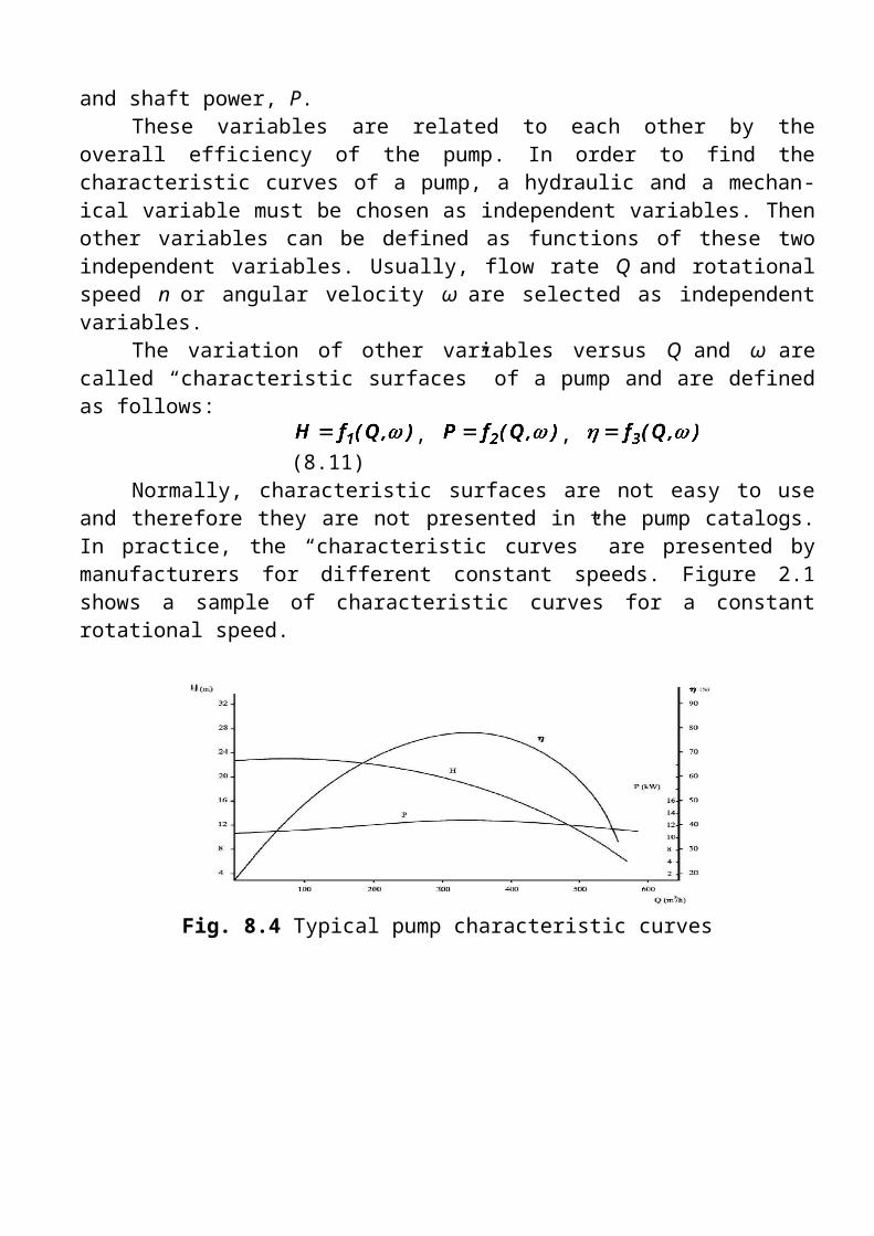
Figure 8.6 Pump liftMaximum pump lift is determined by atmospheric pressure and is given
by expressions 1.3 and 1.4. In theory a lift of about 8 m is feasible but, in practice, would be accompanied by undesirable side effects such as cavitation (formation and destructive collapse of bubbles from partial vaporisation of fluid). The lift should be as small as possible and around 1 m is a normal practical limit.
8.4 Positive-displacement pump types
There are essentially three different types of positive displacement pump used in hydraulic systems.
Gear pumpsThe simplest and most robust positive displacement pump, having just
two moving parts, is the gear pump. Its parts are non-reciprocating, move at constant speed and experience a uniform force. Internal construction, shown in Figure 8.7, consists of just two close meshing gear wheels which rotate as shown. The direction of rotation of the gears should be carefully noted; it is the opposite of that intuitively expected by most people.
As the teeth come out of mesh at the centre, a partial vacuum is formed which draws fluid into the inlet chamber. Fluid is trapped between the outer teeth and the pump housing, causing a continual transfer of fluid from inlet
Figure 8.7 Gear pump

chamber to outlet chamber where it is discharged to the system.Pump displacement is determined by: volume of fluid between each pair
of teeth; number of teeth; and speed of rotation. Note the pump merely delivers a fixed volume of fluid from inlet port to outlet port for each rotation; outlet port pressure is determined solely by design of the rest of the system.
Performance of any pump is limited by leakage and the ability of the pump to withstand the pressure differential between inlet and outlet ports. The gear pump obviously requires closely meshing gears, minimum clearance between teeth and housing, and also between the gear face and side plates. Often the side plates of a pump are designed as deliberately replaceable wear plates. Wear in a gear pump is primarily caused by dirt particles in the hydraulic fluid, so cleanliness and filtration are particularly important.
The pressure differential causes large side loads to be applied to the gear shafts at 45° to the centre line as shown. Typically, gear pumps are used at pressures up to about 150 bar and capacities of around 600 lpm (6751 min-1). Volumetric efficiency of gear pumps at 90% is lowest of the three pump types.
There are some variations of the basic gear pump. In Figure 8.8, gears have been replaced by lobes giving a pump called, not surprisingly, a lobe pump.
Figure 2.8 The lobe pump

Figure 8.9 Further forms of gear pump
Figure 8.9a is another variation called the internal gear pump, where an external driven gear wheel is connected to a smaller internal gear, with fluid separation as gears disengage being performed by a crescent-shaped moulding. Yet another variation on the theme is the gerotor pump of Figure 2.9b, where the crescent moulding is dispensed with by using an internal gear with one less tooth than the outer gear wheel. Internal gear pumps operate at lower capacities and pressures (typically 70 bar) than other pump types.
Vane pumpsThe major source of leakage in a gear pump arises from the small gaps
between teeth, and also between teeth and pump housing. The vane pump reduces this leakage by using spring (or hydraulic) loaded vanes slotted into a driven rotor, as illustrated in the two examples of Figure 2.10.
In the pump shown in Figure 2.10a, the rotor is offset within the housing, and the vanes constrained by a cam ring as they cross inlet and outlet ports. Because the vane tips are held against the housing there is little leakage and the vanes compensate to a large degree for wear at vane tips or in the housing itself. There is still, however, leakage between rotor faces and body
Figure 8.10 Vane pumps

sides. Pump capacity is determined by vane throw, vane cross sectional area and speed of rotation. The difference in pressure between outlet and inlet ports creates a severe load on the vanes and a large side load on the rotor shaft which can lead to bearing failure. The pump in Figure 2.10a is consequently known as an unbalanced vane pump. Figure 2.10b shows a balanced vane pump. This features an elliptical cam ring together with two inlet and two outlet ports.
Pressure loading still occurs in the vanes but the two identical pump halves create equal but opposite forces on the rotor, leading to zero net force in the shaft and bearings. Balanced vane pumps have much improved service lives over simpler unbalanced vane pumps.
Capacity and pressure ratings of a vane pump are generally lower than gear pumps, but reduced leakage gives an improved volumetric efficiency of around 95%.
In an ideal world, the capacity of a pump should be matched exactly to load requirements. Expression 8.6 showed that input power is proportional to system pressure and volumetric flow rate. A pump with too large a capacity wastes energy (leading to a rise in fluid temperature) as excess fluid passes through the pressure relief valve.
Pumps are generally sold with certain fixed capacities and the user has to choose the next largest size. Figure 8.11 shows a vane pump with adjustable capacity, set by the positional relationship between rotor and inner casing, with the inner casing position set by an external screw.
Piston pumpsA piston pump is superficially similar to a motor car engine, and a simple
single cylinder arrangement was shown earlier in Figure 2.2b. Such a simple pump, however, delivering a single pulse of fluid per revolution, generates unacceptably large pressure pulses into the system. Practical piston pumps

therefore employ multiple cylinders and pistons to smooth out fluid delivery, and much ingenuity goes into designing multi-cylinder pumps which are surprisingly compact.
Figure 8.11 Variable displacement vane pump
Figure 8.12 shows one form of radial piston pump. The pump consists of several hollow pistons inside a stationary cylinder block. Each piston has spring-loaded inlet and outlet valves. As the inner cam rotates, fluid is transferred relatively smoothly from inlet port to the outlet port.
The pump of Figure 8.13 uses the same principle, but employs a stationary cam and a rotating cylinder block. This arrangement does not require multiple inlet and outlet valves and is consequently simpler, more reliable, and cheaper. Not surprisingly most radial piston pumps have this construction.
Figure 8.12 Radial piston pump

Fig. 8.13 Piston pump with stationary cam and rotating block
Piston pumps have very high volumetric efficiency (over 98%) and can be used at the highest hydraulic pressures. Being more complex than vane and gear pumps, they are correspondingly more expensive.
Dynamic pumps generally provide a higher flow rate than PDPs and a much steadier discharge but are ineffective in handling high-viscosity liquids. Dynamic pumps also generally need priming; i.e., if they are filled with gas, they cannot suck up a liquid from below into their inlet. The PDP, on the other hand, is self-priming for most applications. A dynamic pump can provide very high flow rates (up to 300,000 gal/min) but usually with moderate pressure rises (a few atmospheres). In contrast, a PDP can operate up to very high pressures (300 atm) but typically produces low flow rates (100 gal/min).
Table 2.1 gives a comparison of the various types of pump.Type Maximum Maximum Variable Positive
pressure (bar) flow (l/min) displacement displacement
Centrifugal 20 3000 No No
Gear 175 300 No Yes
Vane 175 500 Yes Yes
Axial piston (port-plate) 300 500 Yes Yes
Axial piston (valved) 700 650 Yes Yes
In-line piston 1000 100 Yes Yes
Table 2.1 Comparison of hydraulic pump types
Specialist pumps are available for pressures up to about 7000 bar at low flows. The delivery from centrifugal and gear pumps can be made variable by changing the speed of the pump motor with a variable frequency (VF) drive.

8.5 Dynamic pumps
Let us begin our brief look at rotodynamic machines by examining the characteristics of the centrifugal pump. As sketched in Fig. 8.14, this pump consists of an impeller rotating within a casing. Fluid enters axially through the eye of the casing, is caught up in the impeller blades, and is whirled tangentially and radially outward until it leaves through all circumferential parts of the impeller into the diffuser part of the casing. The fluid gains both velocity and pressure while passing through the impeller. The doughnut-shaped diffuser, or scroll, section of the casing decelerates the flow and further in-creases the pressure.
Fig. 8.14 Typical centrifugal pumpThe impeller blades are usually backward-curved, as in Fig. 8.14, but
there are also radial and forward-curved blade designs, which slightly change the output pressure. The blades may be open, i.e., separated from the front casing only by a narrow clearance, or closed, i.e., shrouded from the casing on both sides by an impeller wall. The diffuser may be vaneless, as in Fig. 8.14, or fitted with fixed vanes to help guide the flow toward the exit.
Assuming steady flow, the pump basically increases the total head of the flow between point 1, the eye, and point 2, the exit. From Eq. (8.2), neglecting viscous work, kinetic energy correction factor and heat transfer, this change is denoted by :
, (8.12)
where is the pump head supplied and the losses. The net head is a primary output parameter for any turbomachine. Since Eq. (11.1) is for incompressible flow, it must be modified for gas compressors with large density changes. Usually and are about the same, is no more than a meter or so, and the total pump head is essentially equal to the change in pressure head
(8.13)
The power delivered to the fluid simply equals the specific weight times the discharge times the net head change

This is traditionally called the water horsepower. The power required to drive the pump is the brake horsepower
, (8.14)where is the shaft angular velocity and T the shaft torque. If there were no losses, and brake horsepower would be equal, but of course is actually less, and the efficiency of the pump is defined as
(8.15)
The chief aim of the pump designer is to make as high as possible over as broad a range of discharge Q as possible.
The efficiency is basically composed of three parts: volumetric, hydraulic, and mechanical. The volumetric efficiency is
(8.16)
where is the loss of fluid due to leakage in the impeller-casing clearances. The hydraulic efficiency is
(8.17)
where has three parts: (1) shock loss at the eye due to imperfect match between inlet flow and the blade entrances, (2) friction losses in the blade passages, and (3) circulation loss due to imperfect match at the exit side of the blades. Finally, the mechanical efficiency is
(8.18)
where is the power loss due to mechanical friction in the bearings, packing glands, and other contact points in the machine.
By definition, the total efficiency is simply the product of its three parts (8.19)
The designer has to work in all three areas to improve the pump.To construct an elementary theory of pump performance, we assume
one-dimensional flow and combine idealized fluid-velocity vectors through the impeller with the angular-momentum theorem for a control volume.
The idealized velocity diagrams are shown in Fig. 8.15. The fluid is assumed to enter the impeller at with velocity component tangent to the blade angle plus circumferential speed matching the tip speed of the impeller. Its absolute entrance velocity is thus the vector sum of and
, shown as . Similarly, the flow exits at with component parallel to the blade angle plus tip speed , with resultant velocity .

We applied the angular-momentum theorem to a turbomachine and arrived at a result for the applied torque T
(8.20)
where and are the absolute circumferential velocity components of the flow. The power delivered to the fluid is thus
,or (8.21)
These are the Euler turbomachine equations, showing that the torque, power, and ideal head are functions only of the rotor-tip velocities and
the absolute fluid tangential velocities , independent of the axial velocities (if any) through the machine.
Additional insight is gained by rewriting these relations in another form. From the geometry of Fig. 8.15
or (8.22)
Substituting this into Eq. (8.21) gives
(8.23)
Thus the ideal head relates to the absolute plus the relative kinetic-energy change of the fluid minus the rotor-tip kinetic-energy change. Finally,
Fig. 8.15 Inlet and exit velocity diagrams for an idealized pump impeller.

substituting for from its definition in Eq. (8.12) and rearranging, we obtain the classic relation
(8.24)
This is the Bernoulli equation in rotating coordinates and applies to either two- or three-dimensional ideal incompressible flow.
For a centrifugal pump, the power can be related to the radial velocity tan and the continuity relation
(8.25)
Where and and where and are the
blade widths at inlet and exit. With the pump parameters , , , ,and known, Eqs. (8.12) or Eq. (8.25) is used to compute idealized power and
head versus discharge. The “design’’ flow rate is commonly estimated by assuming that the flow enters exactly normal to the impeller
(8.26)We can expect this simple analysis to yield estimates within percent
for the head, water horsepower, and discharge of a pump. Let us illustrate with an example.
Example 8.1Given are the following data for a commercial centrifugal water pump: in, in, , , speed = 1440 r/min. Estimate (a) the
design-point discharge, (b) the water horsepower, and (c) the head if .
SolutionPart (a) The angular velocity is .
Thus the tip speeds are and
.
From the inlet-velocity diagram, Fig. 8.16, with for design point, we compute
whence the discharge is
Fig. 8.16 inlet-velocity diagram

(The actual pump produces about 3500 gal/min.)
Part (b) The outlet radial velocity follows from
This enables us to construct the outlet-velocity diagram as in Fig. 8.17, given . The tangential component is
The power is then computed from Eq. (8.12) with at the design point
(The actual pump delivers about 125 water horsepower, requiring 147 bhp at 85 percent efficiency.)Part (c) Finally, the head is estimated from Eq. (8.12)
(The actual pump develops about 140-ft head.)
8.5.1 Iso-efficiency Curves
Fig. 8.17 Outlet-velocity diagram

The complete characteristic curves of a pump also include the curves that are called the iso-efficiency curves. In Fig. 8.18 the two-dimensional
complete characteristic curves, with iso-efficiency curves for a turbopump, are shown. These curves are plotted as follows. First the experimentally head-discharge characteristic curve at different speeds of of nominal speed are determined and plotted (solid parabolic lines in the upper plot). This will cover the whole operation range of a pump. The curves are plotted in a non-dimensional system of coordinates, where the non-dimensional characteristic curves of
is obtained
as . Subscript notifies the characteristic curve at normal speed.
Now the efficiency curves of which are obtained from the experiment at the same rotational speeds are plotted, using the same percentage scale for the discharge axis (lower plot). For clarity, only the efficiency curve at nominal speed is shown in this figure. The intersection of this curve with the straight lines of the same efficiency, e.g.
and (maximum efficiency), are then obtained (see the lower plot).
Now, from each efficiency curve, these points are projected to the non-dimensional head-discharge curve on the top plot. Once this procedure is completed for all efficiency and head-discharge curves at different speeds, the point with equal efficiency values are connected to each other, forming a series of closed oval iso-efficiency curves. These curves are very important during the pump selection, since they would show the efficiency of the pump at different conditions and rotational speeds.
If the points of the H = f (Q) curves corresponding to the best operating conditions (maximum efficiency) at the respective speeds are joined together, a parabolic curve is obtained whose apex is at the origin and its axis coincides with the H-axis (solid line in the upper plot). This curve represents the
Fig. 8.18 Characteristic curves for different rotational speeds

optimum operating conditions for the impeller. The other similar curves, dashed lines, show the similar flow conditions, but at different efficiencies.
The characteristic curves of a pump can be obtained by experiments or through theoretical methods.