TURBO IN-LINE BILGE BLOWERS - … · TURBO IN-LINE BILGE BLOWERS INSTALLATION INSTRUCTIONS 09/01...
6
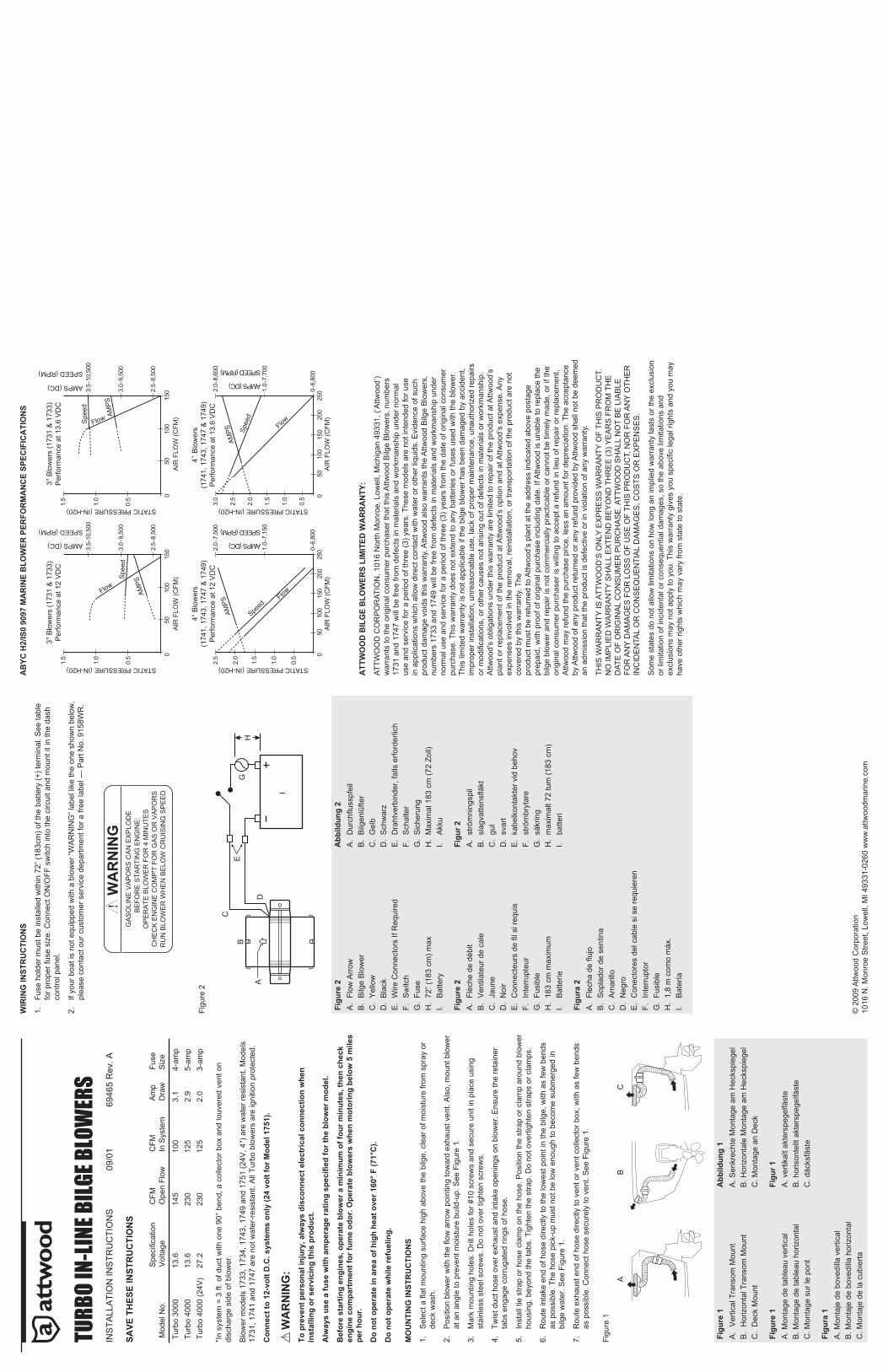
ABYC H2/IS0 9097 MARINE BLOWER PERFORMANCE SPECIFICATIONS ATTWOOD BILGE BLOWERS LIMITED WARRANTY: ATTWOOD CORPORATION, 1016 North Monroe, Lowell, Michigan 49331, (‘Attwood’) warrants to the original consumer purchaser that this Attwood Bilge Blowers, numbers 1731 and 1747 will be free from defects in materials and workmanship under normal use and service for a period of three (3) years. These models are not intended for use in applications which allow direct contact with water or other liquids. Evidence of such product damage voids this warranty. Attwood also warrants the Attwood Bilge Blowers, numbers 1733 and 1749 will be free from defects in materials and workmanship under normal use and service for a period of three (3) years from the date of original consumer purchase. This warranty does not extend to any batteries or fuses used with the blower. This limited warranty is not applicable if the bilge blower has been damaged by accident, improper installation, unreasonable use, lack of proper maintenance, unauthorized repairs or modifications, or other causes not arising out of defects in materials or workmanship. Attwood’s obligations under this warranty are limited to repair of the product at Attwood’s plant or replacement of the product at Attwood’s option and at Attwood’s expense. Any expenses involved in the removal, reinstallation, or transportation of the product are not covered by this warranty. The product must be returned to Attwood’s plant at the address indicated above postage prepaid, with proof of original purchase including date. If Attwood is unable to replace the bilge blower and repair is not commercially practicable or cannot be timely made, or if the original consumer purchaser is willing to accept a refund in lieu of repair or replacement, Attwood may refund the purchase price, less an amount for depreciation. The acceptance by Attwood of any product returned or any refund provided by Attwood shall not be deemed an admission that the product is defective or in violation of any warranty. THIS WARRANTY IS ATTWOOD’S ONLY EXPRESS WARRANTY OF THIS PRODUCT. NO IMPLIED WARRANTY SHALL EXTEND BEYOND THREE (3) YEARS FROM THE DATE OF ORIGINAL CONSUMER PURCHASE. ATTWOOD SHALL NOT BE LIABLE FOR ANY DAMAGES FOR LOSS OF USE OF THIS PRODUCT, NOR FOR ANY OTHER INCIDENTAL OR CONSEQUENTIAL DAMAGES, COSTS OR EXPENSES. Some states do not allow limitations on how long an implied warranty lasts or the exclusion or limitation of incidental or consequential damages, so the above limitations and exclusions may not apply to you. This warranty gives you specific legal rights and you may have other rights which may vary from state to state. 1.5 1.0 0.5 0 150 100 50 0 150 100 50 2.5-8,500 3.0-9,500 3.5-10,500 1.5 1.0 0.5 2.5-8,500 3.0-9,500 3.5-10,500 1.5 0.5 0 150 250 0-6,800 1.0 2.0 2.5 3.0 1.5 0.5 1.0 2.0 100 50 200 0 150 250 100 50 200 2.0-7,500 2.5 1.0-7,150 0-6,800 2.0-8,600 1.0-7,700 TURBO IN-LINE BILGE BLOWERS INSTALLATION INSTRUCTIONS 09/01 69465 Rev. A SAVE THESE INSTRUCTIONS Model No. Specification Voltage CFM Open Flow CFM In System Amp Draw Fuse Size Turbo 3000 13.6 145 100 3.1 4-amp Turbo 4000 13.6 230 125 2.9 5-amp Turbo 4000 (24V) 27.2 230 125 2.0 3-amp *In system = 3 ft. of duct with one 90° bend, a collector box and louvered vent on discharge side of blower. Blower models 1733, 1734, 1743, 1749 and 1751 (24V, 4") are water resistant. Models 1731, 1741 and 1747 are not water-resistant. All Turbo blowers are ignition protected. Connect to 12-volt D.C. systems only (24 volt for Model 1751). WARNING: To prevent personal injury, always disconnect electrical connection when installing or servicing this product. Always use a fuse with amperage rating specified for the blower model. Before starting engines, operate blower a minimum of four minutes, then check engine compartment for fume odor. Operate blowers when motoring below 5 miles per hour. Do not operate in area of high heat over 160° F (71°C). Do not operate while refueling. MOUNTING INSTRUCTIONS Select a flat mounting surface high above the bilge, clear of moisture from spray 1. or deck wash. Position blower with the flow arrow pointing toward exhaust vent. Also, mount 2. blower at an angle to prevent moisture build-up. See Figure 1. Mark mounting holes. Drill holes for #10 screws and secure unit in place using 3. stainless steel screws. Do not over tighten screws. Twist duct hose over exhaust and intake openings on blower. Ensure the retainer 4. tabs engage corrugated rings of hose. Install tie strap or hose clamp on the hose. Position the strap or clamp around 5. blower housing, beyond the tabs. Tighten the strap. Do not overtighten straps or clamps. Route intake end of hose directly to the lowest point in the bilge, with as few bends 6. as possible. The hose pick-up must not be low enough to become submerged in bilge water. See Figure 1. Route exhaust end of hose directly to vent or vent collector box, with as few bends 7. as possible. Connect hose securely to vent. See Figure 1. Figure 1 Figure 1 Abbildung 1 Vertical Transom Mount A. Horizontal Transom Mount B. Deck Mount C. A. Senkrechte Montage am Heckspiegel B. Horizontale Montage am Heckspiegel C. Montage an Deck Figure 1 Figur 1 A. Montage de tableau vertical B. Montage de tableau horizontal C. Montage sur le pont A. vertikalt akterspegelfäste B. horisontellt akterspegelfäste C. däcksfäste Figura 1 A. Montaje de bovedilla vertical B. Montaje de bovedilla horizontal C. Montaje de la cubierta WIRING INSTRUCTIONS Fuse holder must be installed within 72” (183cm) of the battery (+) terminal. See 1. table for proper fuse size. Connect ON/OFF switch into the circuit and mount it in the dash control panel. If your boat is not equipped with a blower “WARNING” label like the one shown 2. below, please contact our customer service department for a free label — Part No. 9158WR. Figure 2 Figure 2 Abbildung 2 Flow Arrow A. Bilge Blower B. Yellow C. Black D. Wire Connectors If Required E. Switch F. Fuse G. 72” (183 cm) max H. Battery I. Durchflusspfeil A. Bilgenlüfter B. Gelb C. Schwarz D. Drahtverbinder, falls erforderlich E. Schalter F. Sicherung G. Maximal 183 cm (72 Zoll) H. Akku I. Figure 2 Figur 2 Flèche de débit A. Ventilateur de cale B. Jaune C. Noir D. Connecteurs de fil si requis E. Interrupteur F. Fusible G. 183 cm maximum H. Batterie I. strömningspil A. slagvattensfläkt B. gul C. svart D. kabelkontakter vid behov E. strömbrytare F. säkring G. maximalt 72 tum (183 cm) H. batteri I. Figura 2 Flecha de flujo A. Soplador de sentina B. Amarillo C. Negro D. Conectores del cable si se requieren E. Interruptor F. Fusible G. 1,8 m como máx. H. Batería I. © 2009 Attwood Corporation 1016 N. Monroe Street, Lowell, MI 49331-0260 www.attwoodmarine.com A B C A B C D E G H 3" Blowers (1731 & 1733) Performance at 12 VDC 4" Blowers (1741, 1743, 1747 & 1749) Performance at 12 VDC 3" Blowers (1731 & 1733) Performance at 13.6 VDC 4” Blowers (1741, 1743, 1747 & 1749) Performance at 13.6 VDC I WARNING GASOLINE VAPORS CAN EXPLODE BEFORE STARTING ENGINE: OPERATE BLOWER FOR 4 MINUTES CHECK ENGINE COMP'T FOR GAS OR VAPORS RUN BLOWER WHEN BELOW CRUISING SPEED STATIC PRESSURE (IN-H20) AIR FLOW (CFM) AIR FLOW (CFM) Flow Flow Flow Flow Speed Speed Speed Speed AMPS AMPS AMPS AMPS AIR FLOW (CFM) AIR FLOW (CFM) STATIC PRESSURE (IN-H20) STATIC PRESSURE (IN-H20) STATIC PRESSURE (IN-H20) AMPS (DC) SPEED (RPM) SPEED (RPM) SPEED (RPM) SPEED (RPM) AMPS (DC) AMPS (DC) AMPS (DC)
Transcript of TURBO IN-LINE BILGE BLOWERS - … · TURBO IN-LINE BILGE BLOWERS INSTALLATION INSTRUCTIONS 09/01...
AB
YC H
2/IS
0 90
97 M
AR
INE
BLO
WER
PER
FOR
MA
NC
E SP
ECIF
ICA
TIO
NS
ATT
WO
OD
BIL
GE
BLO
WER
S LI
MIT
ED W
AR
RA
NTY
:
ATTW
OO
D C
OR
PO
RAT
ION
, 101
6 N
orth
Mon
roe,
Low
ell,
Mic
higa
n 49
331,
(‘A
ttwoo
d’)
war
rant
s to
the
orig
inal
con
sum
er p
urch
aser
that
this
Attw
ood
Bilg
e B
low
ers,
num
bers
17
31 a
nd 1
747
will
be
free
from
def
ects
in m
ater
ials
and
wor
kman
ship
und
er n
orm
al
use
and
serv
ice
for a
per
iod
of th
ree
(3) y
ears
. The
se m
odel
s ar
e no
t int
ende
d fo
r use
in
app
licat
ions
whi
ch a
llow
dire
ct c
onta
ct w
ith w
ater
or o
ther
liqu
ids.
Evi
denc
e of
suc
h pr
oduc
t dam
age
void
s th
is w
arra
nty.
Attw
ood
also
war
rant
s th
e A
ttwoo
d B
ilge
Blo
wer
s,
num
bers
173
3 an
d 17
49 w
ill b
e fre
e fro
m d
efec
ts in
mat
eria
ls a
nd w
orkm
ansh
ip u
nder
no
rmal
use
and
ser
vice
for a
per
iod
of th
ree
(3) y
ears
from
the
date
of o
rigin
al c
onsu
mer
pu
rcha
se. T
his
war
rant
y do
es n
ot e
xten
d to
any
bat
terie
s or
fuse
s us
ed w
ith th
e bl
ower
. Th
is li
mite
d w
arra
nty
is n
ot a
pplic
able
if th
e bi
lge
blow
er h
as b
een
dam
aged
by
acci
dent
, im
prop
er in
stal
latio
n, u
nrea
sona
ble
use,
lack
of p
rope
r mai
nten
ance
, una
utho
rized
repa
irs
or m
odifi
catio
ns, o
r oth
er c
ause
s no
t aris
ing
out o
f def
ects
in m
ater
ials
or w
orkm
ansh
ip.
Attw
ood’
s ob
ligat
ions
und
er th
is w
arra
nty
are
limite
d to
repa
ir of
the
prod
uct a
t Attw
ood’
s pl
ant o
r rep
lace
men
t of t
he p
rodu
ct a
t Attw
ood’
s op
tion
and
at A
ttwoo
d’s
expe
nse.
Any
ex
pens
es in
volv
ed in
the
rem
oval
, rei
nsta
llatio
n, o
r tra
nspo
rtatio
n of
the
prod
uct a
re n
ot
cove
red
by th
is w
arra
nty.
The
prod
uct m
ust b
e re
turn
ed to
Attw
ood’
s pl
ant a
t the
add
ress
indi
cate
d ab
ove
post
age
prep
aid,
with
pro
of o
f orig
inal
pur
chas
e in
clud
ing
date
. If A
ttwoo
d is
una
ble
to re
plac
e th
e bi
lge
blow
er a
nd re
pair
is n
ot c
omm
erci
ally
pra
ctic
able
or c
anno
t be
timel
y m
ade,
or i
f the
or
igin
al c
onsu
mer
pur
chas
er is
will
ing
to a
ccep
t a re
fund
in li
eu o
f rep
air o
r rep
lace
men
t, A
ttwoo
d m
ay re
fund
the
purc
hase
pric
e, le
ss a
n am
ount
for d
epre
ciat
ion.
The
acc
epta
nce
by A
ttwoo
d of
any
pro
duct
retu
rned
or a
ny re
fund
pro
vide
d by
Attw
ood
shal
l not
be
deem
ed
an a
dmis
sion
that
the
prod
uct i
s de
fect
ive
or in
vio
latio
n of
any
war
rant
y.
THIS
WA
RR
AN
TY IS
ATT
WO
OD
’S O
NLY
EX
PR
ES
S W
AR
RA
NTY
OF
THIS
PR
OD
UC
T.
NO
IMP
LIE
D W
AR
RA
NTY
SH
ALL
EX
TEN
D B
EY
ON
D T
HR
EE
(3) Y
EA
RS
FR
OM
TH
E
DAT
E O
F O
RIG
INA
L C
ON
SU
ME
R P
UR
CH
AS
E. A
TTW
OO
D S
HA
LL N
OT
BE
LIA
BLE
FO
R A
NY
DA
MA
GE
S F
OR
LO
SS
OF
US
E O
F TH
IS P
RO
DU
CT,
NO
R F
OR
AN
Y O
THE
R
INC
IDE
NTA
L O
R C
ON
SE
QU
EN
TIA
L D
AM
AG
ES
, CO
STS
OR
EX
PE
NS
ES
.
Som
e st
ates
do
not a
llow
lim
itatio
ns o
n ho
w lo
ng a
n im
plie
d w
arra
nty
last
s or
the
excl
usio
n or
lim
itatio
n of
inci
dent
al o
r con
sequ
entia
l dam
ages
, so
the
abov
e lim
itatio
ns a
nd
excl
usio
ns m
ay n
ot a
pply
to y
ou. T
his
war
rant
y gi
ves
you
spec
ifi c
lega
l rig
hts
and
you
may
ha
ve o
ther
righ
ts w
hich
may
var
y fro
m s
tate
to s
tate
.
1.5
1.0
0.5 0
150
100
500
150
100
50
2.5-
8,50
0
3.0-
9,50
0
3.5-
10,5
00
1.5
1.0
0.5
2.5-
8,50
0
3.0-
9,50
0
3.5-
10,5
00
1.5
0.5 0
150
2500-
6,80
0
1.0
2.0
2.5
3.0
1.5
0.5
1.0
2.0
100
5020
00
150
250
100
5020
0
2.0-
7,50
02.
5
1.0-
7,15
0
0-6,
800
2.0-
8,60
0
1.0-
7,70
0
TURB
O IN
-LIN
E BI
LGE
BLOW
ERS
INS
TALL
ATI
ON
INS
TRU
CTI
ON
S
09/
01
6946
5 R
ev. A
SAVE
TH
ESE
INST
RU
CTI
ON
S
Mod
el N
o.S
pecifi c
atio
n V
olta
geC
FMO
pen
Flow
CFM
In S
yste
mA
mp
Dra
wFu
se
Siz
e
Turb
o 30
0013
.614
510
03.
14-
amp
Turb
o 40
0013
.623
012
52.
95-
amp
Turb
o 40
00 (2
4V)
27.2
230
125
2.0
3-am
p
*In
syst
em =
3 ft
. of d
uct w
ith o
ne 9
0° b
end,
a c
olle
ctor
box
and
louv
ered
ven
t on
disc
harg
e si
de o
f blo
wer
.
Blo
wer
mod
els
1733
, 173
4, 1
743,
174
9 an
d 17
51 (2
4V, 4
") a
re w
ater
resi
stan
t. M
odel
s 17
31, 1
741
and
1747
are
not
wat
er-r
esis
tant
. All
Turb
o bl
ower
s ar
e ig
nitio
n pr
otec
ted.
Con
nect
to 1
2-vo
lt D
.C. s
yste
ms
only
(24
volt
for M
odel
175
1).
WA
RN
ING
:To
pre
vent
per
sona
l inj
ury,
alw
ays
disc
onne
ct e
lect
rical
con
nect
ion
whe
n in
stal
ling
or s
ervi
cing
this
pro
duct
.
Alw
ays
use
a fu
se w
ith a
mpe
rage
ratin
g sp
ecifi
ed fo
r the
blo
wer
mod
el.
Bef
ore
star
ting
engi
nes,
ope
rate
blo
wer
a m
inim
um o
f fou
r min
utes
, the
n ch
eck
engi
ne c
ompa
rtm
ent f
or fu
me
odor
. Ope
rate
blo
wer
s w
hen
mot
orin
g be
low
5 m
iles
per h
our.
Do
not o
pera
te in
are
a of
hig
h he
at o
ver 1
60° F
(71°
C).
Do
not o
pera
te w
hile
refu
elin
g.
MO
UN
TIN
G IN
STR
UC
TIO
NS
Sel
ect a
fl at
mou
ntin
g su
rface
hig
h ab
ove
the
bilg
e, c
lear
of m
oist
ure
from
spr
ay
1.
or
deck
was
h.
Pos
ition
blo
wer
with
the fl o
w a
rrow
poi
ntin
g to
war
d ex
haus
t ven
t. A
lso,
mou
nt
2.
blow
er
at a
n an
gle
to p
reve
nt m
oist
ure
build
-up.
See
Fig
ure
1.
Mar
k m
ount
ing
hole
s. D
rill h
oles
for #
10 s
crew
s an
d se
cure
uni
t in
plac
e us
ing
3.
stai
nles
s st
eel s
crew
s. D
o no
t ove
r tig
hten
scr
ews.
Twis
t duc
t hos
e ov
er e
xhau
st a
nd in
take
ope
ning
s on
blo
wer
. Ens
ure
the
reta
iner
4.
ta
bs e
ngag
e co
rrug
ated
ring
s of
hos
e.
Inst
all t
ie s
trap
or h
ose
clam
p on
the
hose
. Pos
ition
the
stra
p or
cla
mp
arou
nd
5.
blow
er
hous
ing,
bey
ond
the
tabs
. Tig
hten
the
stra
p. D
o no
t ove
rtigh
ten
stra
ps o
r cla
mps
.
Rou
te in
take
end
of h
ose
dire
ctly
to th
e lo
wes
t poi
nt in
the
bilg
e, w
ith a
s fe
w b
ends
6.
as
pos
sibl
e. T
he h
ose
pick
-up
mus
t not
be
low
eno
ugh
to b
ecom
e su
bmer
ged
in
bilg
e w
ater
. See
Fig
ure
1.
Rou
te e
xhau
st e
nd o
f hos
e di
rect
ly to
ven
t or v
ent c
olle
ctor
box
, with
as
few
ben
ds
7.
as p
ossi
ble.
Con
nect
hos
e se
cure
ly to
ven
t. S
ee F
igur
e 1.
Figu
re 1
Figu
re 1
Abb
ildun
g 1
Ver
tical
Tra
nsom
Mou
ntA
. H
oriz
onta
l Tra
nsom
Mou
ntB
. D
eck
Mou
ntC
.
A. S
enkr
echt
e M
onta
ge a
m H
ecks
pieg
elB
. Hor
izon
tale
Mon
tage
am
Hec
kspi
egel
C. M
onta
ge a
n D
eck
Figu
re 1
Figu
r 1A
. Mon
tage
de
tabl
eau
verti
cal
B. M
onta
ge d
e ta
blea
u ho
rizon
tal
C. M
onta
ge s
ur le
pon
t
A. v
ertik
alt a
kter
speg
elfä
ste
B. h
oris
onte
llt a
kter
speg
elfä
ste
C. d
äcks
fäst
e
Figu
ra 1
A. M
onta
je d
e bo
vedi
lla v
ertic
alB
. Mon
taje
de
bove
dilla
hor
izon
tal
C. M
onta
je d
e la
cub
ierta
WIR
ING
INST
RU
CTI
ON
S
Fuse
hol
der m
ust b
e in
stal
led
with
in 7
2” (1
83cm
) of t
he b
atte
ry (+
) ter
min
al. S
ee
1.
tabl
e fo
r pro
per f
use
size
. Con
nect
ON
/OFF
sw
itch
into
the
circ
uit a
nd m
ount
it in
the
dash
co
ntro
l pan
el.
If yo
ur b
oat i
s no
t equ
ippe
d w
ith a
blo
wer
“WA
RN
ING
” lab
el li
ke th
e on
e sh
own
2.
belo
w,
plea
se c
onta
ct o
ur c
usto
mer
ser
vice
dep
artm
ent f
or a
free
labe
l — P
art N
o. 9
158W
R.
Figu
re 2
Figu
re 2
Abb
ildun
g 2
Flow
Arr
owA
. B
ilge
Blo
wer
B.
Yel
low
C.
Bla
ckD
. W
ire C
onne
ctor
s If
Req
uire
dE
. S
witc
hF.
Fu
seG
. 72
” (18
3 cm
) max
H.
Bat
tery
I.
Dur
chfl u
sspf
eil
A.
Bilg
enlü
fter
B.
Gel
bC
. S
chw
arz
D.
Dra
htve
rbin
der,
falls
erfo
rder
lich
E.
Sch
alte
rF.
S
iche
rung
G.
Max
imal
183
cm
(72
Zoll)
H.
Akk
uI.
Figu
re 2
Figu
r 2Fl
èche
de
débi
tA
. V
entil
ateu
r de
cale
B.
Jaun
eC
. N
oir
D.
Con
nect
eurs
de fi l
si r
equi
sE
. In
terr
upte
urF.
Fu
sibl
eG
. 18
3 cm
max
imum
H.
Bat
terie
I.
strö
mni
ngsp
ilA
. sl
agva
ttensfl ä
ktB
. gu
lC
. sv
art
D.
kabe
lkon
takt
er v
id b
ehov
E.
strö
mbr
ytar
eF.
sä
krin
gG
. m
axim
alt 7
2 tu
m (1
83 c
m)
H.
batte
riI.
Figu
ra 2
Flec
ha d
e fl u
joA
. S
opla
dor d
e se
ntin
aB
. A
mar
illo
C.
Neg
roD
. C
onec
tore
s de
l cab
le s
i se
requ
iere
nE
. In
terr
upto
rF.
Fu
sibl
eG
. 1,
8 m
com
o m
áx.
H.
Bat
ería
I. © 2
009
Attw
ood
Cor
pora
tion
1016
N. M
onro
e S
treet
, Low
ell,
MI 4
9331
-026
0 w
ww
.attw
oodm
arin
e.co
m
AB
C
A
B
C
D
EG
H
3" B
low
ers
(173
1 &
173
3)P
erfo
rman
ce a
t 12
VD
C
4" B
low
ers
(174
1, 1
743,
174
7 &
174
9)P
erfo
rman
ce a
t 12
VD
C
3" B
low
ers
(173
1 &
173
3)P
erfo
rman
ce a
t 13.
6 V
DC
4” B
low
ers
(174
1, 1
743,
174
7 &
174
9)P
erfo
rman
ce a
t 13.
6 V
DC
I
WARNING
GA
SO
LIN
E V
AP
OR
S C
AN
EX
PLO
DE
B
EFO
RE
STA
RTI
NG
EN
GIN
E:
OP
ER
ATE
BLO
WE
R F
OR
4 M
INU
TES
CH
EC
K E
NG
INE
CO
MP
'T F
OR
GA
S O
R V
AP
OR
SR
UN
BLO
WE
R W
HE
N B
ELO
W C
RU
ISIN
G S
PE
ED
STATIC PRESSURE (IN-H20)
AIR
FLO
W (C
FM)
AIR
FLO
W (C
FM)
Flow
Flow
Flow
Flow
Spe
ed
Spe
ed
Speed
Spee
d
AMPS
AMPS
AMPS
AMPS
AIR
FLO
W (C
FM)
AIR
FLO
W (C
FM)
STATIC PRESSURE (IN-H20)
STATIC PRESSURE (IN-H20) STATIC PRESSURE (IN-H20)
AMPS (DC)
SPEED (RPM) SPEED (RPM)
SPEED (RPM)SPEED (RPM)
AMPS (DC)
AMPS (DC)AMPS (DC)

TURB
OVEN
TILA
TEUR
S DE
CAL
E EN
LIGN
ED
IRE
CTI
VE
S D
’INS
TALL
ATI
ON
0
9/01
69
465
Rev
. A
CO
NSE
RVE
Z C
ES D
IREC
TIVE
S
N°
de m
odèl
eTe
nsio
n de
sp
écifi
catio
nM
³/MIN
à dé
bit o
uver
tM
³/MIN
dans
le s
ystè
me
Tira
ge e
n am
père
sTa
ille
du
fusi
ble
Turb
o 30
0013
.614
510
03.
14
ampè
res
Turb
o 40
0013
.623
012
52.
95
ampè
res
Turb
o 40
00 (2
4V)
27.2
230
125
2.0
3 am
père
s
*Dan
s le
sys
tèm
e =
91 c
m d
e co
ndui
t ave
c un
e co
urbe
de
90°,
un
coffr
e du
cap
teur
et u
n év
ent à
per
sien
nes
sur l
e cô
té d
e dé
char
ge d
u ve
ntila
teur
.Le
s m
odèl
es d
e ve
ntila
teur
173
3, 1
734,
174
3, 1
749
et 1
751
(24
volts
, 10,
2 cm
) son
t rés
ista
nts
à l’e
au. L
es m
odèl
es
1731
, 174
1 et
174
7 ne
son
t pas
rési
stan
ts à
l’ea
u. T
ous
les
turb
oven
tilat
eurs
son
t pro
tégé
s co
ntre
l’al
lum
age.
Se re
lie à
des
sys
tèm
es d
e 12
vol
ts C
C s
eule
men
t (24
vol
ts p
our l
e m
odèl
e 17
51).
AVE
RTI
SSEM
ENT
:Po
ur é
vite
r tou
te b
less
ure,
déb
ranc
hez
touj
ours
la c
onne
xion
éle
ctriq
ue lo
rs d
e l’i
nsta
llatio
n ou
de
la
répa
ratio
n de
ce
prod
uit.
Util
isez
touj
ours
un
fusi
ble
dont
l’in
tens
ité c
orre
spon
d à
celle
pré
cisé
e po
ur le
m
odèl
e de
ven
tilat
eur.
Ava
nt d
e m
ettr
e le
s m
oteu
rs e
n m
arch
e, fa
ites
fonc
tionn
er le
ven
tilat
eur p
enda
nt
au m
oins
qua
tre
min
utes
, pui
s vé
rifi e
z qu
’il n
’y a
it pa
s d’
odeu
r de
fum
ée d
ans
le c
ompa
rtim
ent m
oteu
r. Fa
ites
fonc
tionn
er le
s ve
ntila
teur
s lo
rsqu
e vo
us n
avig
uez
à m
oins
de
8 ki
lom
ètre
s à
l’heu
re. N
e fa
ites
pas
fonc
tionn
er d
ans
une
zone
de
chal
eur i
nten
se s
upér
ieur
e à
71 °C
. Ne
faite
s pa
s fo
nctio
nner
pen
dant
le
ravi
taill
emen
t en
carb
uran
t.
DIR
ECTI
VES
DE
MO
NTA
GE
Sél
ectio
nnez
une
sur
face
de
mon
tage
pla
te é
levé
e au
-des
sus
de la
cal
e, li
bre
d’hu
mid
ité d
e pu
lvér
isat
ion
ou
1. de
lava
ge d
u po
ntP
lace
z le
ven
tilat
eur a
vec
la fl
èche
de
débi
t poi
ntan
t ver
s l’é
vent
de
sorti
e. In
stal
lez
auss
i le
vent
ilate
ur d
e 2.
man
ière
incl
inée
pou
r évi
ter t
oute
acc
umul
atio
n d’
hum
idité
. Rep
orte
z-vo
us à
la fi
gure
1.
Mar
quez
les
trous
de
mon
tage
. Per
cez
des
trous
pou
r les
vis
n°
10 e
t fi x
ez l’
unité
en
plac
e au
moy
en d
e vi
s en
3.
acie
r ino
xyda
ble.
Ne
serr
ez p
as tr
op le
s vi
s.
Tour
nez
le c
ondu
it su
r les
ouv
ertu
res
de s
ortie
et d
’adm
issi
on d
u ve
ntila
teur
. Ass
urez
-vou
s qu
e le
s on
glet
s de
4.
rete
nue
s’en
clen
chen
t sur
les
anne
aux
ondu
lés
du b
oyau
.In
stal
lez
une
cour
roie
d’a
ttach
e ou
une
brid
e de
ser
rage
sur
le b
oyau
. Pla
cez
la c
ourr
oie
ou la
brid
e au
tour
du
5. bo
îtier
du
vent
ilate
ur, a
u-de
là d
es o
ngle
ts. S
erre
z la
cou
rroi
e. N
e se
rrez
pas
trop
les
cour
roie
s ou
les
brid
es.
Ach
emin
ez l’
extré
mité
d’a
dmis
sion
du
boya
u di
rect
emen
t ver
s le
poi
nt le
plu
s ba
s de
la c
ale,
ave
c au
ssi p
eut d
e 6.
cour
bes
que
poss
ible
. La
repr
ise
du b
oyau
ne
doit
pas
se tr
ouve
r à u
n en
droi
t où
elle
pou
rrai
t être
sub
mer
gée
par l
’eau
de
cale
. Rep
orte
z-vo
us à
la fi
gure
1.
Ach
emin
ez l’
extré
mité
de
sorti
e du
boy
au d
irect
emen
t ver
s l’é
vent
ou
le c
offre
du
capt
eur,
avec
aus
si p
eu d
e 7.
cour
bes
que
poss
ible
. Rel
iez
le b
oyau
sol
idem
ent à
l’év
ent.
Rep
orte
z-vo
us à
la fi
gure
1.
DIR
ECTI
VES
DE
CÂ
BLA
GE
Le p
orte
-fusi
ble
doit
être
inst
allé
à u
ne d
ista
nce
de m
oins
de
183
cm d
e la
bor
ne (+
) de
la b
atte
rie. R
epor
tez-
1. vo
us a
u ta
blea
u po
ur c
onna
ître
le b
on c
alib
re d
u fu
sibl
e. R
elie
z l’i
nter
rupt
eur M
AR
CH
E/A
RR
ÊT
au c
ircui
t et
inst
alle
z-le
sur
le ta
blea
u de
bor
d.S
i vot
re b
atea
u n’
est p
as m
uni d
’une
étiq
uette
« A
VE
RTI
SS
EM
EN
T »
pour
ven
tilat
eur c
omm
e ce
lle q
ui e
st
2. ill
ustré
e ci
-des
sous
, veu
illez
com
mun
ique
r ave
c le
ser
vice
à la
clie
ntèl
e po
ur e
n ob
teni
r une
gra
tuite
men
t -
pièc
e n°
915
8WR
.
SPÉC
IFIC
ATIO
NS
DE
PER
FOR
MA
NC
E D
U V
ENTI
LATE
UR
MA
RIN
AB
YC H
2/IS
0 90
97
GA
RA
NTI
E LI
MIT
ÉE P
OU
R L
ES V
ENTI
LATE
UR
S D
E C
ALE
ATT
WO
OD
R
epor
tez-
vous
au
cata
logu
e de
pro
duits
ou
à at
twoo
dmar
ine.
com
pou
r de
plus
am
ples
rens
eign
emen
ts.
SOPL
ADOR
TUR
BO D
E SE
NTIN
A EN
LÍNE
AIN
STR
UC
CIO
NE
S P
AR
A L
A IN
STA
LAC
ION
0
9/01
69
465
Rev
. A
CO
NSE
RVE
EST
AS
INST
RU
CC
ION
ES
Mod
elo
N.°
Volta
je
espe
cifi c
ado
Fluj
o ab
ierto
en
met
ros
cúbi
cos
por m
inut
oM
etro
s cú
bico
s po
r m
inut
o en
el s
iste
ma
Am
pera
jeTa
mañ
o de
l fu
sibl
e
Turb
o 30
0013
.614
510
03.
14
ampe
rios
Turb
o 40
0013
.623
012
52.
95
ampe
rios
Turb
o 40
00 (2
4V)
27.2
230
125
2.0
3 am
perio
s
*En
el s
iste
ma
= co
nduc
to d
e 91
,4 c
m c
on u
n do
blez
de
90º,
reci
pien
te c
olec
tor y
resp
irade
ro e
n fo
rma
de c
elos
ía
en e
l lat
eral
de
desc
arga
del
sop
lado
r.Lo
s m
odel
os 1
733,
173
4, 1
743,
174
9 y
1751
(24
volti
os, 1
0,2
cm) d
el s
opla
dor s
on re
sist
ente
s al
agu
a. L
os m
odel
os
1731
, 174
1 y
1747
no
son
resi
sten
tes
al a
gua.
Tod
os lo
s so
plad
ores
turb
o es
tán
prot
egid
os c
ontra
ince
ndio
s.C
onéc
telo
s ún
icam
ente
a s
iste
mas
de
12 v
oltio
s de
CC
(24
volti
os p
ara
el m
odel
o 17
51).
AD
VER
TEN
CIA
:Pa
ra e
vita
r les
ione
s pe
rson
ales
, des
cone
cte
siem
pre
la c
onex
ión
eléc
tric
a cu
ando
inst
ale
o re
pare
est
e pr
oduc
to. U
tilic
e si
empr
e un
fusi
ble
con
el a
mpe
raje
esp
ecifi
cado
par
a el
mod
elo
del s
opla
dor.
Ant
es d
e en
cend
er lo
s m
otor
es, p
onga
en
func
iona
mie
nto
el s
opla
dor p
or lo
men
os d
uran
te c
uatr
o m
inut
os, l
uego
co
ntro
le q
ue n
o ha
ya o
lor a
gas
en
el c
ompa
rtim
ento
del
mot
or. P
onga
en
func
iona
mie
nto
los
sopl
ador
es
cuan
do e
l mot
or v
aya
a m
enos
de
8 km
por
hor
a. N
o lo
s en
cien
da e
n lu
gare
s co
n te
mpe
ratu
ras
de m
ás d
e 16
0 ºF
(71
ºC).
No
los
enci
enda
mie
ntra
s ca
rgue
com
bust
ible
.
INST
RU
CC
ION
ES P
AR
A E
L M
ON
TAJE
Elij
a un
a su
perfi
cie
de m
onta
je p
lana
que
se
encu
entre
por
enc
ima
de la
sen
tina,
y q
ue n
o co
nten
ga h
umed
ad
1. pr
oven
ient
e de
l roc
iado
o e
l lav
ado
de la
cub
ierta
.C
oloq
ue e
l sop
lado
r con
la fl
echa
de fl u
jo a
punt
ando
hac
ia e
l res
pira
dero
. Ade
más
, mon
te e
l sop
lado
r en
un
2. án
gulo
par
a ev
itar q
ue s
e ac
umul
e hu
med
ad. V
ea la
Fig
ura
1.M
arqu
e lo
s or
ifi ci
os d
e m
onta
je. P
erfo
re a
guje
ros
para
torn
illos
#10
y a
segu
re la
uni
dad
en e
l lug
ar m
edia
nte
3. to
rnill
os d
e ac
ero
inox
idab
le. N
o aj
uste
los
torn
illos
en
exce
so.
Gire
la m
angu
era
del c
ondu
cto
sobr
e la
s ab
ertu
ras
de s
alid
a y
entra
da e
n el
sop
lado
r. A
segú
rese
de
que
las
4. le
ngüe
tas
del s
ujet
ador
se
enga
nche
n en
los
anill
os c
orru
gado
s de
la m
angu
era.
Inst
ale
una
corr
ea d
e su
jeci
ón o
una
abr
azad
era
para
man
guer
a en
la m
angu
era.
Col
oque
la c
orre
a o
la
5. ab
raza
dera
alre
dedo
r de
la c
aja
del s
opla
dor,
por e
ncim
a de
las
leng
üeta
s. A
just
e la
cor
rea.
No
ajus
te e
n ex
ceso
las
corr
eas
ni la
s ab
raza
dera
s.E
nsar
te e
l ext
rem
o de
ent
rada
de
la m
angu
era
dire
ctam
ente
en
el p
unto
más
baj
o de
la s
entin
a, c
on la
men
or
6. ca
ntid
ad d
e do
blec
es p
osib
les.
El e
xtre
mo
de s
ucci
ón d
e la
man
guer
a de
be e
star
a u
na a
ltura
que
no
perm
ita
su s
umer
sión
en
el a
gua
de la
sen
tina.
Vea
la F
igur
a 1.
Ens
arte
el e
xtre
mo
de s
alid
a de
la m
angu
era
dire
ctam
ente
en
el re
spira
dero
o e
n el
reci
pien
te c
olec
tor d
el
7. re
spira
dero
, con
la m
enor
can
tidad
de
dobl
eces
pos
ible
s. C
onec
te la
man
guer
a al
resp
irade
ro e
n fo
rma
segu
ra.
Vea
la F
igur
a 1.
INST
RU
CC
ION
ES P
AR
A E
L C
AB
LEA
DO
El p
orta
fusi
bles
se
debe
inst
alar
a u
na d
ista
ncia
máx
ima
de 1
,8 m
del
term
inal
pos
itivo
(+) d
e la
bat
ería
. 1.
Con
sulte
la ta
bla
para
con
ocer
el t
amañ
o ap
ropi
ado
del f
usib
le. C
onec
te e
l int
erru
ptor
de
EN
CE
ND
IDO
/A
PA
GA
DO
al c
ircui
to e
inst
álel
o en
el p
anel
de
cont
rol.
Si s
u em
barc
ació
n no
pos
ee u
na e
tique
ta d
e “P
RE
CA
UC
ION
” en
el s
opla
dor,
com
o la
que
se
mue
stra
a
2. co
ntin
uaci
ón, c
omun
íque
se c
on e
l dep
arta
men
to d
e at
enci
ón a
l clie
nte
para
obt
ener
una
etiq
ueta
gra
tis: P
ieza
N
.° 9
158W
R.
ESPE
CIF
ICA
CIO
NES
DE
AB
YC H
2/IS
O 9
097
SOB
RE
EL F
UN
CIO
NA
MIE
NTO
DEL
SO
PLA
DO
R M
AR
INO
GA
RA
NTI
A L
IMIT
AD
A D
E LO
S SO
PLA
DO
RES
DE
SEN
TIN
A A
TTW
OO
D:
Con
sulte
el c
atál
ogo
del p
rodu
cto
o vi
site
attw
oodm
arin
e.co
m p
ara
cono
cer l
os d
etal
les.
TURB
O-IN
LINE
-BIL
GENL
ÜFTE
RIN
STA
LLA
TIO
NS
AN
LEIT
UN
G
09/
01
6946
5 R
ev. A
BEW
AH
REN
SIE
DIE
SE A
NLE
ITU
NG
AU
F
Mod
elln
umm
erA
nsch
luss
span
nung
CFM
be
i Fris
chlu
ftC
FMbe
i Um
luft
Stro
mbe
darf
Wer
t der
S
iche
rung
Turb
o 30
0013
.614
510
03.
14
ATu
rbo
4000
13.6
230
125
2.9
5 A
Turb
o 40
00 (2
4V)
27.2
230
125
2.0
3 A
*In
eine
m S
yste
m m
it 1
m (3
Fuß
) Roh
rleitu
ng m
it ei
nem
90˚
Krü
mm
er, e
inem
Ver
teile
rkas
ten
und
eine
m m
it La
mel
len
vers
ehen
en A
usla
ss a
uf d
er A
blei
tung
ssei
te d
es L
üfte
rs.
Die
Lüf
term
odel
le 1
733,
173
4, 1
743,
174
9 un
d 17
51 (2
4V, 4
Zol
l) si
nd w
asse
rfest
. Die
Lüf
term
odel
le 1
731,
174
1 un
d 17
47 s
ind
nich
t was
serfe
st. A
lle T
urbo
-Lüf
ter s
ind
expl
osio
nsge
schü
tzt.
Dar
f nur
an
12 V
olt G
leic
hspa
nnun
gssy
stem
e an
gesc
hlos
sen
wer
den
(24
Volt
bei M
odel
l 175
1).
WA
RN
UN
G:
Um
Ver
letz
unge
n zu
ver
mei
den,
tren
nen
Sie
beim
Inst
allie
ren
oder
bei
der
War
tung
das
Ger
ät v
on d
er
Stro
mqu
elle
. Ver
wen
den
Sie
nur e
ine
Sich
erun
g m
it de
m fü
r die
ses
Lüfte
rmod
ell a
ngeg
eben
en W
ert.
Bev
or S
ie M
otor
en s
tart
en, l
asse
n Si
e de
n Lü
fter f
ür m
inde
sten
s vi
er M
inut
en la
ufen
. Kon
trol
liere
n Si
e da
nn d
en M
otor
raum
auf
Tre
ibst
offd
ämpf
e. B
ei e
iner
Fah
rt v
on w
enig
er a
ls 8
km
/h (5
Mei
len
pro
Stun
de)
lass
en S
ie d
en L
üfte
r im
mer
lauf
en. D
er L
üfte
r dar
f nic
ht in
bei
ein
er h
ohen
Um
gebu
ngst
empe
ratu
r von
m
ehr a
ls 7
1° C
(160
° F) b
etrie
ben
wer
den.
Bei
m T
anke
n ni
cht v
erw
ende
n.
MO
NTA
GEA
NLE
ITU
NG
Wäh
len
Sie
ein
e ho
ch ü
ber d
er B
ilge
gele
gene
Mon
tagefl ä
che,
wel
che
nich
t Feu
chtig
keit
durc
h S
pritz
- ode
r 1.
Spü
lwas
ser a
usge
setz
t ist
Brin
gen
Sie
den
Lüf
ter s
o an
, das
s de
r Strö
mun
gspf
eil i
n R
icht
ung
des
Abz
ugsr
ohrs
zei
gt. M
ontie
ren
Sie
den
2.
Lüfte
r auc
h m
it ei
ner N
eigu
ng, s
odas
s si
ch k
eine
Feu
chtig
keit
ansa
mm
eln
kann
. Sie
he A
bbild
ung
1.M
arki
eren
Sie
die
Mon
tage
löch
er. B
ohre
n S
ie d
ie L
öche
r für
Sch
raub
en N
r. 10
und
bef
estig
en S
ie d
ie E
inhe
it 3.
mit
rost
freie
n S
chra
uben
. Zie
hen
Sie
die
Sch
raub
en n
icht
zu
fest
an.
Zi
ehen
Sie
die
Lüf
tung
ssch
läuc
he ü
ber d
ie A
bluf
t- un
d E
inla
ssöf
fnun
gen
am L
üfte
r. S
telle
n S
ie s
iche
r, da
ss d
ie
4. B
efes
tigun
gsla
sche
n in
die
Rin
grip
pen
der S
chlä
uche
ein
grei
fen.
Brin
gen
Sie
Bef
estig
ungs
büge
l ode
r Sch
lauc
hkle
mm
en a
n de
n S
chlä
uche
n an
. Bef
estig
en S
ie d
ie B
ügel
ode
r 5.
die
Kle
mm
en h
inte
r den
Las
chen
am
Lüf
terg
ehäu
se. Z
iehe
n S
ie d
en B
ügel
an.
Zie
hen
Sie
die
Büg
el o
der
Kle
mm
en n
icht
zu
fest
an.
Führ
en S
ie d
ie E
inla
ssöf
fnun
g de
s S
chla
uche
s m
it so
wen
ig B
iegu
ngen
als
mög
lich
dire
kt z
um n
iedr
igst
en
6. P
unkt
der
Bilg
e. D
iese
Ein
lass
öffn
ung
darf
aber
nic
ht s
o tie
f sei
n, d
ass
sie
ins
Bilg
enw
asse
r ein
tauc
hen
könn
te.
Sie
he A
bbild
ung
1.Fü
hren
Sie
die
Aus
lass
öffn
ung
des
Sch
lauc
hes
mit
so w
enig
Bie
gung
en w
ie m
öglic
h di
rekt
zum
Abz
ug o
der
7. de
m A
bzug
ssam
mel
kana
l. Ve
rbin
den
Sie
den
Sch
lauc
h si
cher
mit
dem
Abz
ug. S
iehe
Abb
ildun
g 1.
VER
DR
AH
TUN
GSA
NLE
ITU
NG
Der
Sic
heru
ngsh
alte
r dar
f nur
mit
eine
r max
imal
en D
raht
läng
e vo
n 18
3cm
(72
Zoll)
vom
Plu
s-P
ol (+
) des
Akk
us
1. en
tfern
t mon
tiert
wer
den.
Ric
htig
er W
ert f
ür d
ie S
iche
rung
sie
he T
abel
le. F
ügen
Sie
ein
en E
IN-/A
US
-Sch
alte
r in
den
Stro
mkr
eis
ein
und
baue
n S
ie d
iese
n in
das
Arm
atur
enbr
ett e
in.
Falls
das
Boo
t nic
ht m
it ei
nem
Sch
ild “W
AR
NU
NG
” wie
dem
unt
en g
ezei
gten
aus
gerü
stet
ist,
setz
en S
ie s
ich
2. bi
tte m
it un
sere
r Kun
dend
iens
tabt
eilu
ng w
egen
ein
es G
ratis
etik
etts
(Tei
lenu
mm
er 9
158W
R) i
n Ve
rbin
dung
.
LEIS
TUN
GSD
ATEN
DES
MA
RIN
ELÜ
FTER
S A
BYC
H2/
ISO
909
7
EIN
GES
CH
RÄ
NK
TE G
AR
AN
TIE
VON
ATT
WO
OD
FÜ
R B
ILG
ENLÜ
FTER
:Ei
nzel
heite
n si
ehe
Prod
uktk
atal
og o
der a
ttwoo
dmar
ine.
com
.
TURB
O-IN
LINE
-SLA
GVAT
TENS
FLÄK
TAR
MO
NTE
RIN
GS
AN
VIS
NIN
G
09/
01
6946
5 R
ev. A
SPA
RA
DES
SA A
NVI
SNIN
GA
R
Mod
elln
rS
pänn
ings
spec
ifi ka
tion
cfm
Öpp
et fl
öde
cfm
I sys
tem
etS
tröm
förb
rukn
ing
Säk
rings
stor
lek
Turb
o 30
0013
.614
510
03.
14
ATu
rbo
4000
13.6
230
125
2.9
5 A
Turb
o 40
00 (2
4V)
27.2
230
125
2.0
3 A
*I s
yste
met
= 3
fots
(0,9
2 m
) rör
ledn
ing
med
en
90˚ v
inke
l, en
upp
sam
lings
box
och
en g
alle
rförs
edd
vent
ilatio
nsöp
pnin
g på
fl äk
tens
utlo
ppss
ida.
Fläk
tmod
elle
rna
1733
, 173
4, 1
743,
174
9 oc
h 17
51 (2
4 V,
10,
16 c
m) ä
r vat
tenb
estä
ndig
a. M
odel
lern
a 17
31, 1
741
och
1747
är i
nte
vatte
nbes
tänd
iga.
Sam
tliga
Tur
bo-fl
äkta
r är t
änds
pänn
ings
skyd
dade
.
Ans
lut e
nbar
t till
12
V lik
strö
mss
yste
m (2
4 V
för m
odel
l 175
1).
VA
RN
ING
!K
oppl
a al
ltid
bort
str
ömkä
llan
när d
en h
är p
rodu
kten
mon
tera
s el
ler u
nder
hålls
för a
tt fö
rhin
dra
pers
onsk
ador
. Anv
änd
allti
d en
säk
ring
med
det
am
pere
tal s
om s
pecifi c
eras
för fl
äkt
mod
elle
n. In
nan
mot
orst
arte
n, k
ör fl
äkte
n un
der m
inst
fyra
min
uter
och
kon
trol
lera
sed
an a
tt de
t int
e fö
reko
mm
er n
ågra
ån
gor i
mot
orru
mm
et. K
ör fl
äkta
rna
vid
lägr
e ha
stig
hete
r än
ca 9
km
per
tim
me.
Får
ej a
nvän
das
i myc
ket
varm
a ut
rym
men
, öve
r 160
°F (7
1 ˚C
). Få
r ej a
nvän
das
unde
r tan
knin
g.
MO
NTE
RIN
GSA
NVI
SNIN
GV
älj e
tt pl
ant u
nder
lag
högt
ova
nför
köl
en, f
ritt f
rån
vatte
nstä
nk o
ch d
äcks
vatte
n.1.
Pla
cera
fl äk
ten
med
strö
mni
ngsp
ilen
rikta
d m
ot u
tsug
sven
tilat
ions
öppn
inge
n. M
onte
ra ä
ven fl ä
kten
i vi
nkel
för
2. at
t för
hind
ra fu
ktan
sam
ling.
Se fi g
ur 1
.M
ärk
ut m
onte
rings
håle
n. B
orra
skr
uvhå
len
(nr 1
0) o
ch s
kruv
a fa
st e
nhet
en m
ed ro
stfri
a st
ålsk
ruva
r. S
pänn
inte
3.
åt s
kruv
arna
för h
årt.
Vrid
lufts
lang
en ö
ver u
tsug
s- o
ch in
sugs
öppn
inga
rna
på fl
äkte
n. S
äker
stäl
l att
fästfl i
karn
a gr
iper
in i
de rä
ffl ad
e 4.
ringa
rna
på s
lang
en.
Mon
tera
bun
tban
d el
ler s
lang
kläm
ma
på s
lang
en. P
lace
ra b
untb
ande
t elle
r sla
ngkl
ämm
an k
ring fl ä
kthu
set,
5. bo
rtom
fl ik
arna
. Spä
nn å
t bun
tban
det.
Spä
nn in
te å
t bun
tban
den
elle
r sla
ngkl
ämm
orna
för h
årt.
Dra
sla
ngen
s in
sugs
ände
dire
kt ti
ll kö
lens
lägs
ta p
unkt
och
med
så
få b
öjar
som
möj
ligt.
Sla
ngen
s 6.
insu
gsöp
pnin
g få
r doc
k in
te p
lace
ras
så lå
gt a
tt de
n ha
mna
r i s
lagv
attn
et. S
e fi g
ur 1
.D
ra s
lang
ens
utsu
gsän
de d
irekt
till
vent
ilatio
nsöp
pnin
gen
elle
r ven
tilat
ions
upps
amlin
gsbo
xen
med
så
få b
öjar
7.
som
möj
ligt.
Ans
lut s
lang
en o
rden
tligt
till
vent
ilatio
nsöp
pnin
gen.
Se fi g
ur 1
.
KO
PPLI
NG
SAN
VISN
ING
AR
Säk
rings
hålla
ren
får i
nte
mon
tera
s lä
ngre
bor
t frå
n de
n po
sitiv
a (+
) bat
terip
olen
än
72 tu
m (1
83 c
m).
Se
tabe
llen
1. fö
r rät
t säk
rings
stor
lek.
Ans
lut T
ILL/
FRÅ
N-s
tröm
bryt
aren
till
kret
sen
och
mon
tera
den
på
inst
rum
entp
anel
en.
Om
båt
en ä
r int
e ut
rust
ad m
ed e
n “V
AR
NIN
G”-fl ä
ktde
kal l
ikt d
en s
om v
isas
ned
an, k
onta
kta
vår
2. ku
ndtjä
nsta
vdel
ning
för a
tt få
en
deka
l gra
tis —
art.
nr 9
158W
R.
AB
YC H
2/IS
0 90
97-P
RES
TAN
DA
SPEC
IFIK
ATIO
NER
FÖ
R F
LÄK
T FÖ
R M
AR
INT
BR
UK
BEG
RÄ
NSA
D G
AR
AN
TI F
ÖR
ATT
WO
OD
-SLA
GVA
TTEN
SFLÄ
KTA
R:
Se p
rodu
ktka
talo
gen
elle
r attw
oodm
arin
e.co
m fö
r fler
det
alje
r.
1.5
1.0
0.5 0
150
100
500
150
100
50
2.5-
8,50
0
3.0-
9,50
0
3.5-
10,5
00
1.5
1.0
0.5
2.5-
8,50
0
3.0-
9,50
0
3.5-
10,5
00
1.5
0.5 0
150
2500-
6,80
0
1.0
2.0
2.5
3.0
1.5
0.5
1.0
2.0
100
5020
00
150
250
100
5020
0
2.0-
7,50
02.
5
1.0-
7,15
0
0-6,
800
2.0-
8,60
0
1.0-
7,70
0
1.5
1.0
0.5 0
150
100
500
150
100
50
2.5-
8,50
0
3.0-
9,50
0
3.5-
10,5
00
1.5
1.0
0.5
2.5-
8,50
0
3.0-
9,50
0
3.5-
10,5
00
1.5
0.5 0
150
2500-
6,80
0
1.0
2.0
2.5
3.0
1.5
0.5
1.0
2.0
100
5020
00
150
250
100
5020
0
2.0-
7,50
02.
5
1.0-
7,15
0
0-6,
800
2.0-
8,60
0
1.0-
7,70
0
1.5
1.0
0.5 0
150
100
500
150
100
50
2.5-
8,50
0
3.0-
9,50
0
3.5-
10,5
00
1.5
1.0
0.5
2.5-
8,50
0
3.0-
9,50
0
3.5-
10,5
00
1.5
0.5 0
150
2500-
6,80
0
1.0
2.0
2.5
3.0
1.5
0.5
1.0
2.0
100
5020
00
150
250
100
5020
0
2.0-
7,50
02.
5
1.0-
7,15
0
0-6,
800
2.0-
8,60
0
1.0-
7,70
0
1.5
1.0
0.5 0
150
100
500
150
100
50
2.5-
8,50
0
3.0-
9,50
0
3.5-
10,5
00
1.5
1.0
0.5
2.5-
8,50
0
3.0-
9,50
0
3.5-
10,5
00
1.5
0.5 0
150
2500-
6,80
0
1.0
2.0
2.5
3.0
1.5
0.5
1.0
2.0
100
5020
00
150
250
100
5020
0
2.0-
7,50
02.
5
1.0-
7,15
0
0-6,
800
2.0-
8,60
0
1.0-
7,70
0
1.5
1.0
0.5 0
150
100
500
150
100
50
2.5-
8,50
0
3.0-
9,50
0
3.5-
10,5
00
1.5
1.0
0.5
2.5-
8,50
0
3.0-
9,50
0
3.5-
10,5
00
1.5
0.5 0
150
2500-
6,80
0
1.0
2.0
2.5
3.0
1.5
0.5
1.0
2.0
100
5020
00
150
250
100
5020
0
2.0-
7,50
02.
5
1.0-
7,15
0
0-6,
800
2.0-
8,60
0
1.0-
7,70
0
Vent
ilate
urs
de 7
,6 c
m (1
731
et 1
733)
, pe
rform
ance
à 1
2 vo
lts C
CS
opla
dore
s de
7,6
cm
(173
1 y
1733
): fu
ncio
nam
ient
o a
12 v
oltio
s de
CC
3 Zo
ll Lü
fter (
1731
& 1
733)
Lei
stun
g be
i 12
V G
leic
hstro
m3
tum
s (7
,62
cm) fl
äkt
ar (1
731
& 1
733)
, pr
esta
nda
vid
12 V
liks
tröm
Vent
ilate
urs
de 1
0,2
cm (1
741,
17
43, 1
747
et 1
749)
, per
form
ance
à
12 v
olts
CC
Sop
lado
res
de 1
0,2
cm (1
741,
174
3,
1747
y 1
749)
: fun
cion
amie
nto
a 12
vol
tios
de C
C
4 Zo
ll Lü
fter (
1741
, 174
3, 1
747
&
1749
) Lei
stun
g be
i 12
V
Gle
ichs
trom
4 tu
ms
(10,
16 c
m) fl
äkt
ar (1
741,
17
43, 1
747
& 1
749)
, pre
stan
da v
id
12 V
liks
tröm
Vent
ilate
urs
de 7
,6 c
m (1
731
et 1
733)
, pe
rform
ance
à 1
3,6
volts
CC
Sop
lado
res
de 7
,6 c
m (1
731
y 17
33):
func
iona
mie
nto
a 13
,6 v
oltio
s de
CC
3 Zo
ll Lü
fter (
1731
& 1
733)
Lei
stun
g be
i 13
,6 V
Gle
ichs
trom
3 tu
ms
(7,6
2 cm
) fl ä
ktar
(173
1 &
173
3),
pres
tand
a vi
d 13
,6 V
liks
tröm
Vent
ilate
urs
de 1
0,2
cm (1
741,
17
43, 1
747
et 1
749)
, per
form
ance
à
13,6
vol
ts C
C
Sop
lado
res
de 1
0,2
cm (1
741,
174
3,
1747
y 1
749)
: fun
cion
amie
nto
a 13
,6 v
oltio
s de
CC
4 Zo
ll Lü
fter (
1741
, 174
3, 1
747
& 1
749)
Lei
stun
g be
i 13,
6 V
G
leic
hstro
m
4 tu
ms
(10,
16 c
m) fl
äkt
ar (1
741,
17
43, 1
747
& 1
749)
, pre
stan
da v
id
13,6
V li
kströ
m
PRESSION STATIQUE (DANS L’EAU)
PRESION ESTATICA (cm H2O)
STATISCHER DRUCK (Zoll-Wasser)
STATISKT TRYCK (TUM VATTEN)
PRESSION STATIQUE (DANS L’EAU)
PRESION ESTATICA (cm H2O)
STATISCHER DRUCK (Zoll-Wasser)
STATISKT TRYCK (TUM VATTEN)
PRESSION STATIQUE (DANS L’EAU)
PRESION ESTATICA (cm H2O)
STATISCHER DRUCK (Zoll-Wasser)
STATISKT TRYCK (TUM VATTEN)
PRESSION STATIQUE (DANS L’EAU)
PRESION ESTATICA (cm H2O)
STATISCHER DRUCK (Zoll-Wasser)
STATISKT TRYCK (TUM VATTEN)
DÉ
BIT
D’A
IR (M
³/MIN
)FL
UJO
DE
AIR
E (m
etro
s cú
bico
s po
r min
uto)
FLU
JO D
E A
IRE
(met
ros
cúbi
cos
por m
inut
o)
FLU
JO D
E A
IRE
(met
ros
cúbi
cos
por m
inut
o)
FLU
JO D
E A
IRE
(met
ros
cúbi
cos
por m
inut
o)
LUFT
DU
RC
HFL
US
S (C
FM)
LUFT
DU
RC
HFL
US
S (C
FM)
LUFT
DU
RC
HFL
US
S (C
FM)
LUFT
DU
RC
HFL
US
S (C
FM)
LUFT
FLÖ
DE
(KU
BIK
FOT
PE
R M
IN)
LUFT
FLÖ
DE
(KU
BIK
FOT
PE
R M
IN)
LUFT
FLÖ
DE
(KU
BIK
FOT
PE
R M
IN)
LUFT
FLÖ
DE
(KU
BIK
FOT
PE
R M
IN)
DÉ
BIT
D’A
IR (M
³/MIN
)
DÉ
BIT
D’A
IR (M
³/MIN
)
DÉ
BIT
D’A
IR (M
³/MIN
)
Debit
Debit
Flöde
Flujo
Fluss
Flujo
Fluss
Flöde
Debit
Debit
Flöde
Flujo
Fluss
Flujo
Fluss
Flöde
Vite
sse
Vite
sse
Has
tighe
tVe
loci
dad
Um
dre-
hung
en
Velo
cida
dU
mdr
e-hu
ngen
Has
tighe
t
Vitess
e
Vite
sse
Has
tighe
tVe
loci
dad
Um
dreh
unge
n
Velocid
ad
Umdrehu
ngen
Hastig
het
AMPÈ
RES
AMPE
RIO
SST
RO
MA
AMPÈ
RES
AMPE
RIO
SST
RO
MA
AMPÈ
RES
AMPE
RIO
SST
RO
MA
AMPÈ
RES
AMPE
RIO
SST
RO
MA
AMPÈRES (CC)
AMPERIOS (CC) AMPERIOS (CC)
AMPERIOS (CC)AMPERIOS (CC)
STROM (Gleichstrom)
STROM (Gleichstrom)
STROM (Gleichstrom)
STROM (Gleichstrom)
A (LIKSTRÖM) A (LIKSTRÖM)
A (LIKSTRÖM) A (LIKSTRÖM)
VITESSE (TR/MIN)
VELOCIDAD (RPM)
VELOCIDAD (RPM)
VELOCIDAD (RPM)
VELOCIDAD (RPM)
UMDREHUNGEN PRO MINUTE
UMDREHUNGEN PRO MINUTE
UMDREHUNGEN PRO MINUTE
UMDREHUNGEN PRO MINUTE
HASTIGHET (VARV/MIN)
HASTIGHET (VARV/MIN)
HASTIGHET (VARV/MIN)
HASTIGHET (VARV/MIN)
VITESSE (TR/MIN)
AMPÈRES (CC)
AVERTISSEM
ENT
LES
VA
PE
UR
S D
'ES
SE
NC
E P
EU
VE
NT
EX
PLO
SE
RA
VA
NT
DE
ME
TTR
E L
E M
OTE
UR
EN
MA
RC
HE
:FA
ITE
S F
ON
CTI
ON
NE
R L
E V
EN
TILA
TEU
R P
EN
DA
NT
QU
ATR
E M
INU
TES
VÉ
RIF
IEZ
QU
'IL N
'Y A
PA
S D
'ES
SE
NC
E O
U D
E V
AP
EU
RS
DA
NS
LE
C
OM
PA
RTI
ME
NT
MO
TEU
RFA
ITE
S F
ON
CTI
ON
NE
R L
E V
EN
TILA
TEU
R L
OR
S D
E N
AV
IGA
TIO
N
À B
AS
SE
VIT
ES
SE
PRECAUCION
LOS
VA
PO
RE
S D
E L
A G
AS
OLI
NA
PU
ED
EN
SE
R IN
FLA
MA
BLE
SA
NTE
S D
E E
NC
EN
DE
R E
L M
OTO
R:
PO
NG
A E
N F
UN
CIO
NA
MIE
NTO
EL
SO
PLA
DO
R
DU
RA
NTE
4 M
INU
TOS
CO
NTR
OLE
QU
E N
O H
AY
A G
AS
ES
NI V
AP
OR
ES
EN
EL
CO
MP
AR
TIM
EN
TO D
EL
MO
TOR
PO
NG
A E
N F
UN
CIO
NA
MIE
NTO
EL
SO
PLA
DO
R C
UA
ND
O S
E
EN
CU
EN
TRE
DE
BA
JO D
E L
A V
ELO
CID
AD
DE
CR
UC
ER
O
WARNUNG
TRE
IBS
TOFF
DÄ
MP
FE K
ÖN
NE
N E
XP
LOD
IER
EN
VO
R D
EM
STA
RTE
N D
ES
MO
TOR
S:
LAS
SE
N S
IE D
EN
LÜ
FTE
R V
IER
MIN
UTE
N L
AN
G L
AU
FEN
.Ü
BE
RP
RÜ
FEN
SIE
DE
N M
OTO
PR
RA
UM
AU
F G
AS
E O
DE
R D
ÄM
PFE
.LA
SS
EN
SIE
DE
N L
ÜFT
ER
BE
I KLE
INE
RE
R A
LS
RE
ISE
GE
SC
HW
IND
IGK
EIT
LA
UFE
N.
VARNING!
BE
NS
INÅ
NG
OR
ÄR
EX
PLO
SIV
AIN
NA
N M
OTO
RN
STA
RTA
S:
KÖ
R F
LÄK
TEN
UN
DE
R 4
MIN
UTE
RK
ON
TRO
LLE
RA
ATT
DE
T IN
TE F
ÖR
EK
OM
ME
R G
AS
ELL
ER
Å
NG
OR
I M
OTO
RR
UM
ME
TA
KTI
VE
RA
FLÄ
KTE
N V
ID F
ÄR
D U
ND
ER
M
AR
SC
HH
AS
TIG
HE
TEN

MOUNTING INSTRUCTIONSReminder:To prevent personal injury, disconnect one of the main batteryleads prior to installing the blower.
1. Select a flat mounting surface high above the bilge, on thetransom or under the deck. Blower should be mounted highand dry, clear of moisture from spray or deck wash.
2. Position blower with fan nose cone pointing toward exhaustvent. Also, mount blower at an angle to prevent moisturebuild-up. See Figure 1
3. Mark mounting holes using blower mounting feet as a tem-plate. Drill holes for #10 screws.
4. Secure unit in place using stainless steel screws. Do not overtighten screws, as this will crack the mounting feet.
5. Twist duct hose over exhaust and intake openings on blower.Ensure the retainer tabs engage corrugated rings of hose.
6. Install tie strap or hose clamp on the hose. Position the strap orclamp around blower housing, beyond the tabs. Tighten thestrap. When using a hose clamp, tighten until snug — 8 in/lb.(.5N.m) max. Do not overtighten straps or clamps.
7. Route intake end of hose directly to the lowest point in thebilge, with as few bends as possible. The hose pick-up mustbe below the top of the engine stringers, but not low enoughto become submerged in normal bilge water accumulation.See Figure 1
8. Route exhaust end of hose directly to vent or vent collectorbox, with as few bends as possible. Connect hose securelyto vent. See Figure 1
Figure 1
VerticalTransom Mount
DeckMount
HorizontalTransom Mount
FEATURES
Turbo In-Line Bilge Blowers provide ventilation for engine compart-ments, bilges, and marine head closets. Their unique fan blade iscomputer-designed using the latest in aerospace technology.
The blowers’ compact in-line design allows for installation inconfined areas under the deck or on the transom; their built-inmounting feet allow vertical or horizontal installation. Tabs on thehose flanges grip the ventilation hose and prevent hose clampsfrom sliding off after installation.
• 1745 model is a 24-Volt D.C., 4" (102mm) blower with a 1,000hour rating. It is rated for 230 CFM (6.5 cubic meters/min.)at open flow at 27.5-Volts. Current Draw = 2.5-Amps.
Blower model 1745 is water resistant. All Turbo Blowersare ignition protected and meet ABYC and Coast Guard SafetyStandards.
Connect to 24-volt D.C. systems only.
WARNING:To prevent personal injury, always disconnect electricalconnection when installing or servicing this product.
Always use a fuse with amperage rating specified for theblower model. Failure to do so could result in serious personalinjury or fire hazards.
Before starting engines, operate blower a minimum of fourminutes, then check engine compartment for fume odor.
Do not operate in area of high heat over 160° F (71°C).
Do not operate while refueling.
REQUIRED FOR INSTALLATION
• Drill and suitable drill bit
• Screwdriver
• Two #10 x 1/2" (13mm) stainless steel pan head screws
• Corrugated vinyl duct hose, 4" (102mm) I.D. hose
• Two tie straps or hose clamps for 4" (102mm) I.D. hose
• Fuse—4-amp for 4" (102mm) blower,
• Suitable in-line fuse holder
• 5-amp ON/OFF switch
• 16-gauge wire
• Crimp-on wire connectors for 16-gauge wire
3®
Attwood marine hardware, navigational lighting, bilge pumps, and othermarine accessories are specified more than any other brand by America’sbest-known boat manufacturers as original equipment. Look to Attwoodfor quality replacement parts and marine accessories.
SAVE THESE INSTRUCTIONS
Form Number 69284 Rev. B 03-10
Turbo In-Line 24-Volt D.C.Bilge BlowersInstallation Instructions
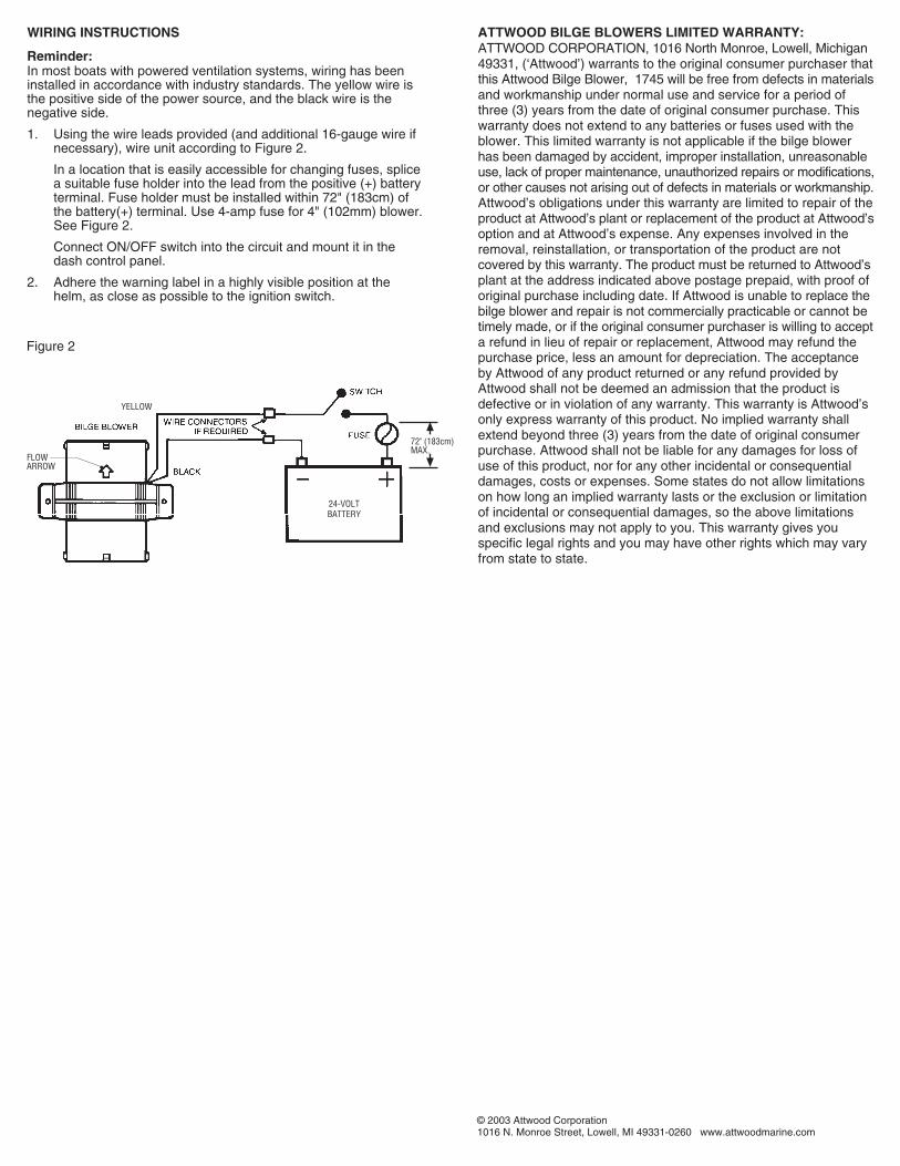
WIRING INSTRUCTIONS
Reminder:In most boats with powered ventilation systems, wiring has beeninstalled in accordance with industry standards. The yellow wire isthe positive side of the power source, and the black wire is thenegative side.
1. Using the wire leads provided (and additional 16-gauge wire ifnecessary), wire unit according to Figure 2.
In a location that is easily accessible for changing fuses, splicea suitable fuse holder into the lead from the positive (+) batteryterminal. Fuse holder must be installed within 72" (183cm) ofthe battery(+) terminal. Use 4-amp fuse for 4" (102mm) blower.See Figure 2.
Connect ON/OFF switch into the circuit and mount it in thedash control panel.
2. Adhere the warning label in a highly visible position at thehelm, as close as possible to the ignition switch.
Figure 2
ATTWOOD BILGE BLOWERS LIMITED WARRANTY:ATTWOOD CORPORATION, 1016 North Monroe, Lowell, Michigan49331, (‘Attwood’) warrants to the original consumer purchaser thatthis Attwood Bilge Blower, 1745 will be free from defects in materialsand workmanship under normal use and service for a period ofthree (3) years from the date of original consumer purchase. Thiswarranty does not extend to any batteries or fuses used with theblower. This limited warranty is not applicable if the bilge blowerhas been damaged by accident, improper installation, unreasonableuse, lack of proper maintenance, unauthorized repairs or modifications,or other causes not arising out of defects in materials or workmanship.Attwood’s obligations under this warranty are limited to repair of theproduct at Attwood’s plant or replacement of the product at Attwood’soption and at Attwood’s expense. Any expenses involved in theremoval, reinstallation, or transportation of the product are notcovered by this warranty. The product must be returned to Attwood’splant at the address indicated above postage prepaid, with proof oforiginal purchase including date. If Attwood is unable to replace thebilge blower and repair is not commercially practicable or cannot betimely made, or if the original consumer purchaser is willing to accepta refund in lieu of repair or replacement, Attwood may refund thepurchase price, less an amount for depreciation. The acceptanceby Attwood of any product returned or any refund provided byAttwood shall not be deemed an admission that the product isdefective or in violation of any warranty. This warranty is Attwood’sonly express warranty of this product. No implied warranty shallextend beyond three (3) years from the date of original consumerpurchase. Attwood shall not be liable for any damages for loss ofuse of this product, nor for any other incidental or consequentialdamages, costs or expenses. Some states do not allow limitationson how long an implied warranty lasts or the exclusion or limitationof incidental or consequential damages, so the above limitationsand exclusions may not apply to you. This warranty gives youspecific legal rights and you may have other rights which may varyfrom state to state.
72" (183cm)MAX.
YELLOW
24-VOLTBATTERY
FLOWARROW •
© 2003 Attwood Corporation1016 N. Monroe Street, Lowell, MI 49331-0260 www.attwoodmarine.com

INSTALLATIONRappel:Avant d'éviter des blessures personnelles, débrancher l'une desbornes de la batterie principale avant d'installer le ventilateur.
1. Choisir une surface plate au dessus de la cale, sur le tableauarrière ou sous le pont. Le ventilateur doit être installé dans unespace élevé et sec, à l'abri de l'humidité provenantd'éclaboussures d'eau ou du lavage du pont.
2. Placer l'avant du ventilateur dans la direction du conduitd'échappement. Placer également le ventilateur dans uneposition angulaire pour éviter l'accumulation d'humidité. Voirtableau 1.
3. Marquer les trous en utilisant les pieds du ventilateur commegabarit. Percer des trous pour les vis #10.
4. Fixer l'appareil avec des vis en acier inoxydable. Ne pas serrerles vis afin d'éviter de craquer les pieds.
5. Placer le conduit sur la sortie d'échappement et l'entrée d'airdu ventilateur. S'assurer que les languettes de fixation se fixesur les anneaux du conduit ondulé.
6. Installer la courroie de fixation ou le collier de serrage surle conduit. Placer la courroie ou le collier de serrage autourdu boîtier du ventilateur au delà deslanguettes. Serrer lacourroie. Lorsque vous utilisez un collier de serrage, serrezdoucement — 8 po/lb (.5N.m) max. Ne pas trop serrer lescourroies ou colliers de serrage.
7. Placer l'arrivée d'air du conduit directement au point le plus basdans la cale, avec le moins de coudes possible. Le pointd'arrivée doit être inférieur à la partie supérieure de l'armaturedu moteur mais pas trop bas où il pourrait être submergé parl'accumulation normale d'eau dans la cale. Voir tableau 1.
8. Placer l'échappement et le conduit au tuyau d'échappement ouau boîtier d'échappement avec le moins de coudes possible.Bien fixer le conduit. Voir tableau 1.
Support vertical dutableau arrière
Support du pont
Support horizontal dutableau arrière
CARACTÉRISTIQUES
Les ventilateurs de cale Turbo en ligne fournissent la ventilationpour les compartiments à moteur, les fonds de cale et les WC.Conçue par ordinateur, leur unique pale de ventilateur est à lapointe de la technologie aérospatiale.
La conception compacte en ligne de ce ventilateur permet uneinstallation dans un espace restreint sous le pont ou sur le tableauarrière; les pieds incorporés permettent une installation verticale ouhorizontale. Des languettes sur les colliers de serrage des tuyauxse fixe sur le tuyau de ventilation et empêche les colliers deserrage de bouger après l'installation.
• Le modèle 1745 est un ventilateur de 4" (102 mm), 24-voltsCD avec une capacité de 1000 heures. Sa capacité est de230 pieds cube-minute (6,5 mètres cube-minute) au débitmaximum de 27,5-volts. Appel de courant = 2,5-ampères.
Les modèles de ventilateurs 1745 sont résistants à l'eau. Tous lesventilateurs Turbo sont protégés du démarreur et sont conformesaux normes de l'ABYC et de la Garde côtière.
Raccorder seulement aux systèmes de 24-volts CD.
ATTENTION:Afin d'éviter toute blessure personnelle, toujours débrancherlors de l'installation ou de l'entretien de ce produit.
Toujours utiliser un fusible avec l'ampérage indiqué pour lemodèle de ce ventilateur. Sinon, il y a risque de gravesblessures personnelles et de feu.
Avant le démarrage d'un moteur, mettre en marche leventilateur pendant au moins quatre minutes, puis vérifierpour l'odeur d'émanation.
Ne pas mettre en marche dans un endroit ou la chaleurdépasse 71o C.
Ne pas mettre en marche durant le ravitaillement de carburant.
NÉCESSAIRE À L'INSTALLATION:
• Perceuse et mèche appropriée
• Tournevis
• Deux vis en acier inoxydable à tête cylindrique #10 x 13mm
• Conduit en vinyle ondulé, tuyau I.D. de 102mm
• Deux attaches ou colliers de serrage pour tuyau I.D. de 102mm
• Fusible— 4-ampères pour ventilateur de 102mm
• Support à fusible en ligne approprié
• Commutateur MARCHE/ARRET de 5-ampères
• Fil de calibre 16
• Raccords à sertir pour fil de calibre 16
Tableau 1
3®
L’équipement maritime, l’éclairage de navigation, les pompes de caleet autre matériel marin d’Attwood sont plus spécifiés que tout autreéquipement comme matériel d’origine par les fabricants de bateaules plus renommés d’Amérique. Attwood vous offre des pièces derechange et des accessoires marins de qualité.
GARDÉ LES RENSEIGNMENT
Numéro du formulaire 69284 Rev. B 03-10
Renseignment Pour,Ventilateurs De Cale TurboEn Linge, 24-Volt CD

JAUNE
BATTERIE DE24-VOLTS
•FLECHE DE DIRECTION D’AIR
FUSIBLE
COMMUTATEUR
RACCORDS DE FILSI NÉCESSAIRE
VENTILATEUR DE CALE
72" (183 CMMAX
NOIR
INSTALLATION ÉLECTRIQUERappel:Dans la plupart des bateaux munis de ventilateur à moteur,l'installation électrique est conforme aux normes de cette industrie.Le fil jaune est le côté positif de la source de pouvoir et le noir, lecôté négatif.
1. En utilisant la borne de fil incluse (et si nécessaire le fil decalibre 16), raccorder l'appareil conformément au tableau 2.
Dans un endroit où il est facile de changer les fusibles, épisserun support à fusible approprié vers la borne provenant de laborne positive (+) de la batterie. Le support à fusible doit êtreinstallé dans un espace ne dépassant pas 183cm de la bornepositive (+) de la batterie. Utiliser un fusible de 4-ampères pourle ventilateur de 102mm. Voir table 2.
Raccorder le commutateur MARCHE/ARRET au circuit etinstaller dans le panneau de contrôle du tableau de bord.
2. Fixer l'étiquette d'avertissement dans une position bien visibleprès de la barre et à côté du démarreur.
GARANTIE LIMITÉE D'ATWOOD DE VENTILATEUR DE CALE:Attwood Corporation, 1016 North Monroe, Lowell, Michigan 49331 (Attwood) garantit àl'acheteur d'origine que le ventilateur de cale Attwood 1745 n'aura aucun défaut de matériauou de main-d'oeuvre dans des conditions normales d'entretien et d'utilisation, pendant unepériode de trois (3) ans à partir de la date d'achat originale. Cette garantie ne s'applique pasaux batteries ou fusibles utilisées avec le ventilateur. Cette garantie limitée ne s'applique pasau ventilateur s'il est endommagé par suite d'un accident, d'une installation inappropriée,d'une mauvaise utilisation, d'un manque d'entretien approprié, de réparations ou modifica-tions non autorisées ou autres causes ne découlant pas de matériau ou de main-d'oeuvre.Par vertu de cette garantie, Attwood est tenue de réparer l'article dans les usines d'Atwood oude le remplacer sans frais au choix d'Atwood. Cette garantie ne vise pas les dépensesassociées au démontage, à l'installation ou au transport du produit. L'acheteur doit retournerle produit port payé, sous assurance et accompagné de preuve portant la date d'achat. SiAttwood ne peut remplacer le ventilateur de cale ou que la réparation ne soit pas pratique oueffectuée dans une période de temps raisonnable ou si l'acheteur d'origine est disposé àaccepter un remboursement au lieu de réparation ou remplacement, Attwood remboursera leprix d'achat moins un montant pour la dépréciation. Le fait qu'Attwood accepte le retour d'unproduit ou offre un remboursement à l'acheteur n'implique pas une déclaration par Attwoodque le produit est défectueux ou n'est pas conforme à la garantie. La garantie d'Atwood est laseule garantie accordée à ces produits. Aucune garantie implicite n'est accordée au delà dela période de trois (3) ans à partir de la date d'achat originale. Attwood ne peut être tenueresponsable des dommages, d'une utilisation diminuée de ce produit, de dommagesaccessoires ou consécutifs, de coûts ou dépenses. Puisque certains états ne permettent pasde limites sur la durée des garanties implicites ou l'exclusion ou la limite des dommagesaccessoires ou consécutifs, les limites ou exclusions indiquées ci-dessus ne s'appliquentpeut-être pas à vous. Cette garantie vous accorde des droits légaux spécifiques et il se peutque vous ayez d'autres droits selon l'état où vous habitez.
Tableau 2
© 2003 Attwood Corporation1016 N. Monroe Street, Lowell, MI 49331-0260 www.attwoodmarine.com