
Learning in the Cloud! Cloud Computing for Teachers & Schools
Upload
assistant-mechanical-engineerCategory
view
629download
3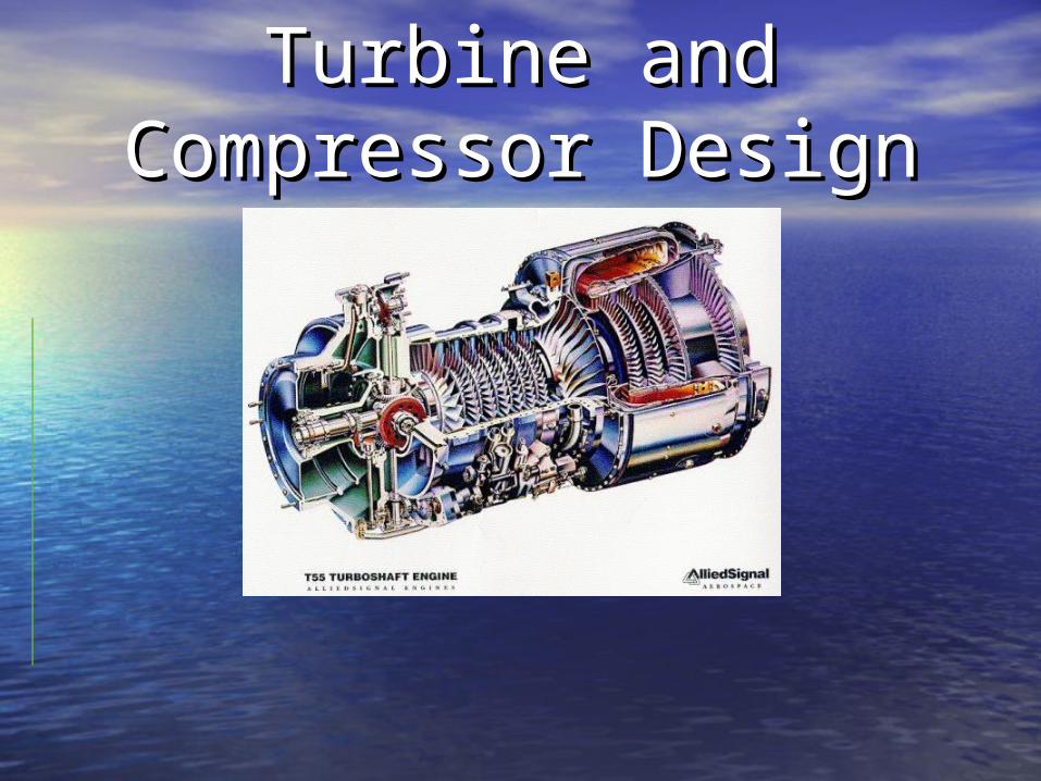
Turbine and Turbine and Compressor DesignCompressor Design
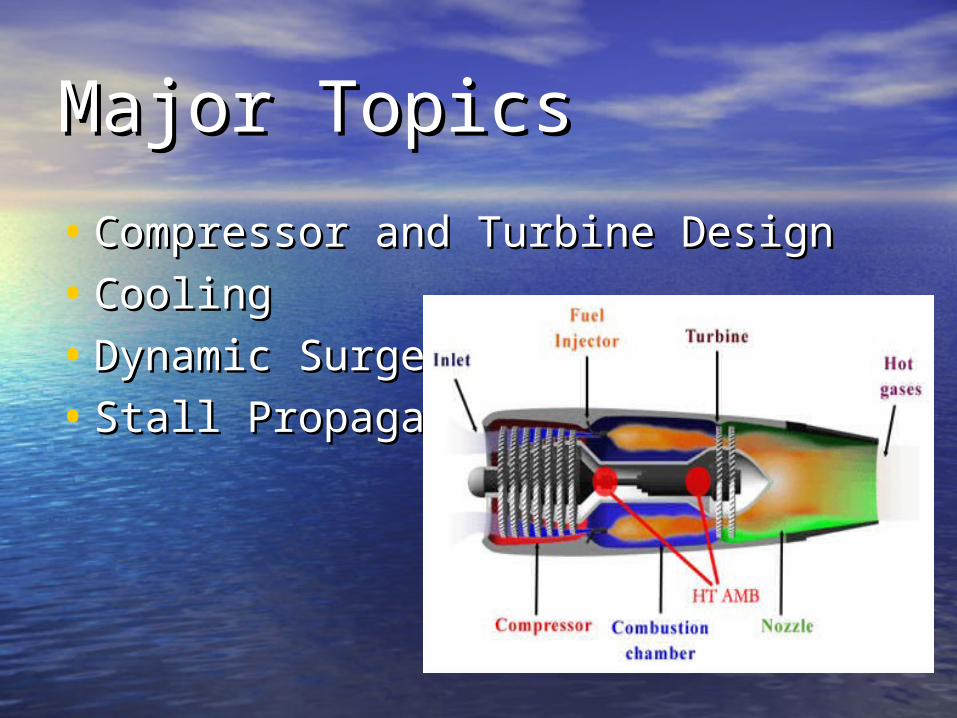
Major TopicsMajor Topics
• Compressor and Turbine DesignCompressor and Turbine Design
• CoolingCooling
• Dynamic SurgeDynamic Surge
• Stall PropagationStall Propagation
BackgroundBackgroundHistory:History:• First gas turbine was developed in 1872 by Dr. F. First gas turbine was developed in 1872 by Dr. F.
Stolze.Stolze.
Gas Turbine Engine…What does it do?Gas Turbine Engine…What does it do?• Generates thrust by mixing compressed ambient Generates thrust by mixing compressed ambient
air with fuel and combusting the mixture through air with fuel and combusting the mixture through a nozzle to propel an object forward or to produce a nozzle to propel an object forward or to produce shaft work. shaft work.
How Does it Work?How Does it Work?• Newton’s third lawNewton’s third law
For every action, there is an equal For every action, there is an equal and opposite reaction.and opposite reaction.
• As the working fluid is exhausted out the As the working fluid is exhausted out the nozzle of the gas turbine engine, the nozzle of the gas turbine engine, the object that the engine is attached to is object that the engine is attached to is pushed forward. In the case of generating pushed forward. In the case of generating shaft work, the shaft turns a generator shaft work, the shaft turns a generator which produces electrical power. which produces electrical power.
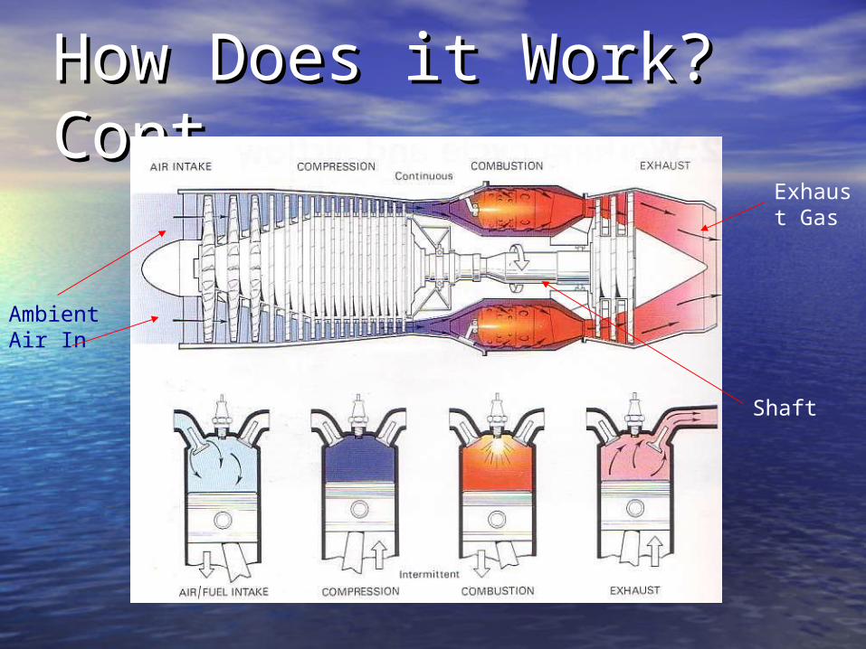
How Does it Work? How Does it Work? Cont.Cont.
Shaft
Exhaust Gas
Ambient Air In

OperationOperation• Compressor is connected to the turbine via Compressor is connected to the turbine via
a shaft. The turbine provides the turning a shaft. The turbine provides the turning moment to turn the compressor. moment to turn the compressor.
• The turning turbine rotates the compressor The turning turbine rotates the compressor fan blades which compresses the incoming fan blades which compresses the incoming air. air.
• Compression occurs through rotors and Compression occurs through rotors and stators within the compression region. stators within the compression region. – Rotors (Rotate with shaft)Rotors (Rotate with shaft)– Stators (Stationary to shaft)Stators (Stationary to shaft)
Types of Gas TurbinesTypes of Gas Turbines• Centrifugal Centrifugal
– Compressed air output is around the outer perimeter of Compressed air output is around the outer perimeter of engine engine
• AxialAxial– Compressed air output is directed along the centerline Compressed air output is directed along the centerline
of the engine of the engine
• Combination of BothCombination of Both– Compressed air output is initially directed along center Compressed air output is initially directed along center
shaft of engine and then is compressed against the shaft of engine and then is compressed against the perimeter of engine by a later stage.perimeter of engine by a later stage.
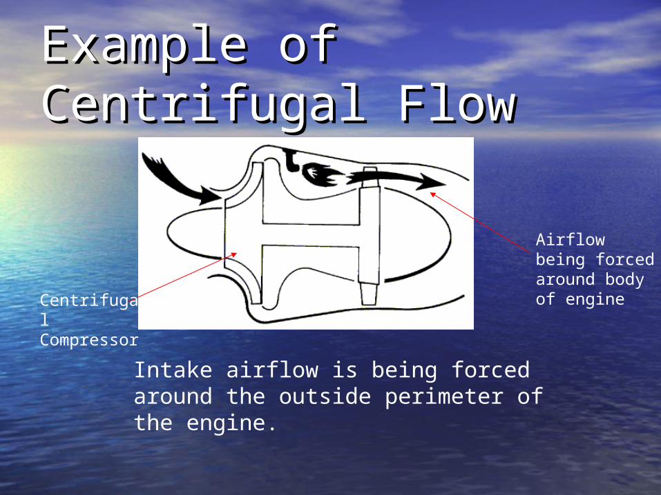
Example of Centrifugal Example of Centrifugal FlowFlow
Intake airflow is being forced around the outside perimeter of the engine.
Centrifugal Compressor
Airflow being forced around body of engine

Example of Axial FlowExample of Axial Flow
Intake airflow is forced down the center shaft of the engine.
Multistage Axial Compressor
Center Shaft

Example of Example of Combination FlowCombination Flow
Intake Air Flow
Axial Compressor
Centrifugal Compressor
Intake air flow is forced down the center shaft initially by axially compressor stages, and then forced against engine perimeter by the centrifugal compressor.
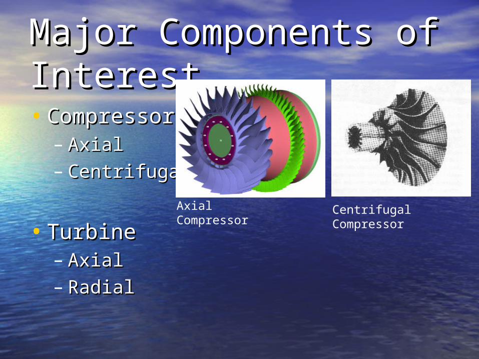
Major Components of Major Components of InterestInterest• CompressorCompressor
– Axial Axial – CentrifugalCentrifugal
• TurbineTurbine– AxialAxial– RadialRadial
Axial Compressor Centrifugal Compressor
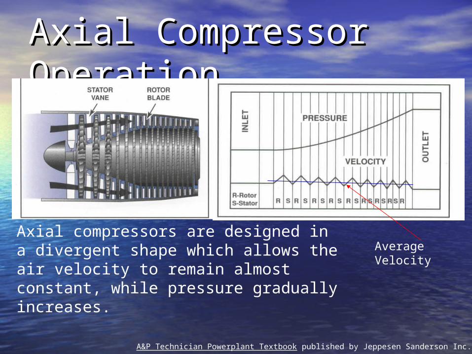
Axial Compressor Axial Compressor OperationOperation
A&P Technician Powerplant Textbook published by Jeppesen Sanderson Inc., 1997
Axial compressors are designed in a divergent shape which allows the air velocity to remain almost constant, while pressure gradually increases.
Average Velocity
Axial Compressor Axial Compressor Operation cont.Operation cont.• The airflow comes in through the inlet The airflow comes in through the inlet
and first comes to the compressor rotor. and first comes to the compressor rotor. – Rotor is rotating and is what draws the Rotor is rotating and is what draws the
airflow into the engine.airflow into the engine.– After the rotor is the stator which does not After the rotor is the stator which does not
move and it redirects the flow into the next move and it redirects the flow into the next stage of the compressor. stage of the compressor.
• Air flows into second stage.Air flows into second stage.– Process continues and each stage gradually Process continues and each stage gradually
increases the pressure throughout the increases the pressure throughout the compressor.compressor.
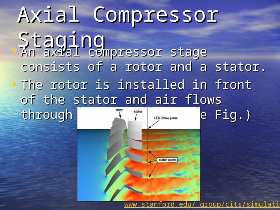
Axial Compressor Axial Compressor StagingStaging
• An axial compressor stage consists of a An axial compressor stage consists of a rotor and a stator. rotor and a stator.
• The rotor is installed in front of the The rotor is installed in front of the stator and air flows through stator and air flows through accordingly. (See Fig.)accordingly. (See Fig.)
www.stanford.edu/ group/cits/simulation/
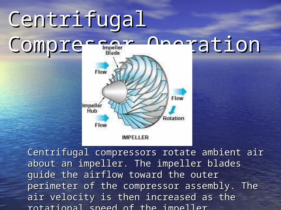
Centrifugal Compressor Centrifugal Compressor OperationOperation
Centrifugal compressors rotate ambient air about Centrifugal compressors rotate ambient air about an impeller. The impeller blades guide the airflow an impeller. The impeller blades guide the airflow toward the outer perimeter of the compressor toward the outer perimeter of the compressor assembly. The air velocity is then increased as assembly. The air velocity is then increased as the rotational speed of the impeller increases. the rotational speed of the impeller increases.

Axial Turbine Axial Turbine OperationOperation
Hot combustion gases expand, airflow pressure and temperature drops. This drop over the turbine blades creates shaft work which rotates the compressor assembly.
Axial Turbine with airflow Airflow around rotor
Airflow through stator

Radial Turbine Radial Turbine OperationOperation
• Same operation Same operation characteristics as axial characteristics as axial flow turbine.flow turbine.
• Radial turbines are Radial turbines are simpler in design and less simpler in design and less expensive to expensive to manufacture. manufacture.
• They are designed much They are designed much like centrifugal like centrifugal compressors. compressors.
• Airflow is essentially Airflow is essentially expanded outward from expanded outward from the center of the turbine.the center of the turbine.
Radial Flow Turbine
Gas Turbine IssuesGas Turbine Issues
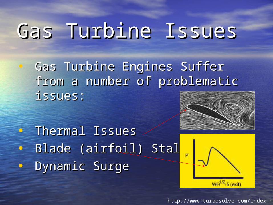
• Gas Turbine Engines Suffer from a Gas Turbine Engines Suffer from a number of problematic issues: number of problematic issues:
• Thermal IssuesThermal Issues
• Blade (airfoil) Stalls Blade (airfoil) Stalls
• Dynamic SurgeDynamic Surge
http://www.turbosolve.com/index.html
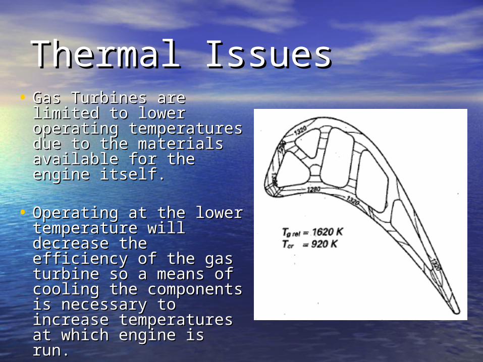
Thermal IssuesThermal Issues• Gas Turbines are Gas Turbines are
limited to lower limited to lower operating temperatures operating temperatures due to the materials due to the materials available for the engine available for the engine itself. itself.
• Operating at the lower Operating at the lower temperature will temperature will decrease the efficiency decrease the efficiency of the gas turbine so a of the gas turbine so a means of cooling the means of cooling the components is components is necessary to increase necessary to increase temperatures at which temperatures at which engine is run. engine is run.
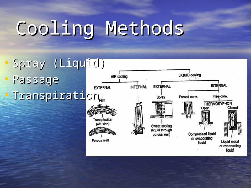
Cooling MethodsCooling Methods
• Spray (Liquid)Spray (Liquid)
• Passage Passage
• Transpiration Transpiration
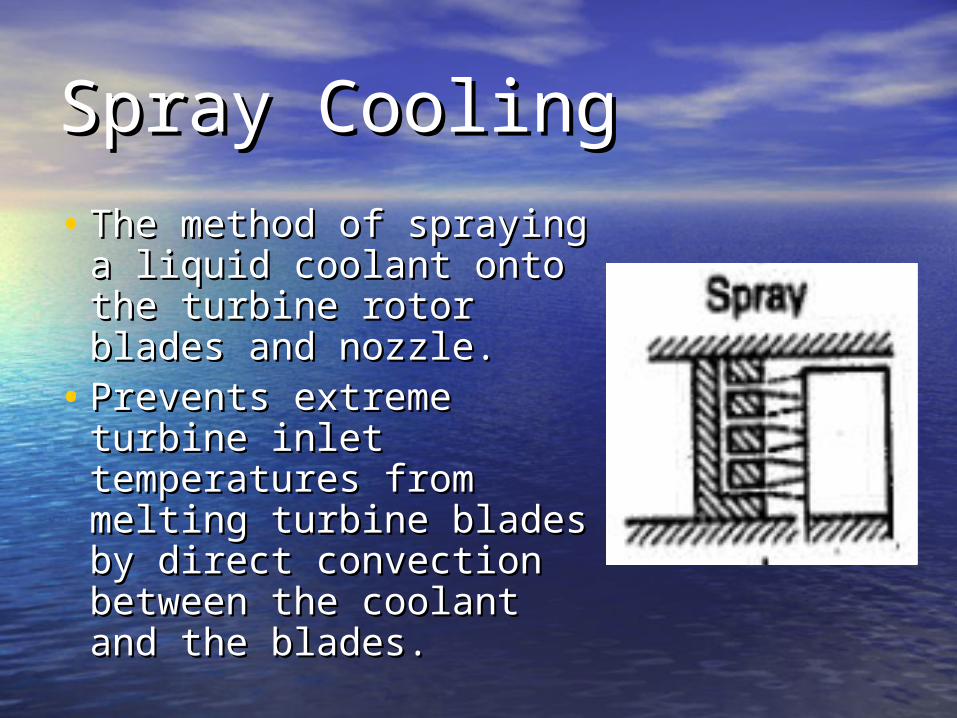
Spray CoolingSpray Cooling
• The method of spraying The method of spraying a liquid coolant onto the a liquid coolant onto the turbine rotor blades and turbine rotor blades and nozzle. nozzle.
• Prevents extreme Prevents extreme turbine inlet turbine inlet temperatures from temperatures from melting turbine blades melting turbine blades by direct convection by direct convection between the coolant and between the coolant and the blades. the blades.
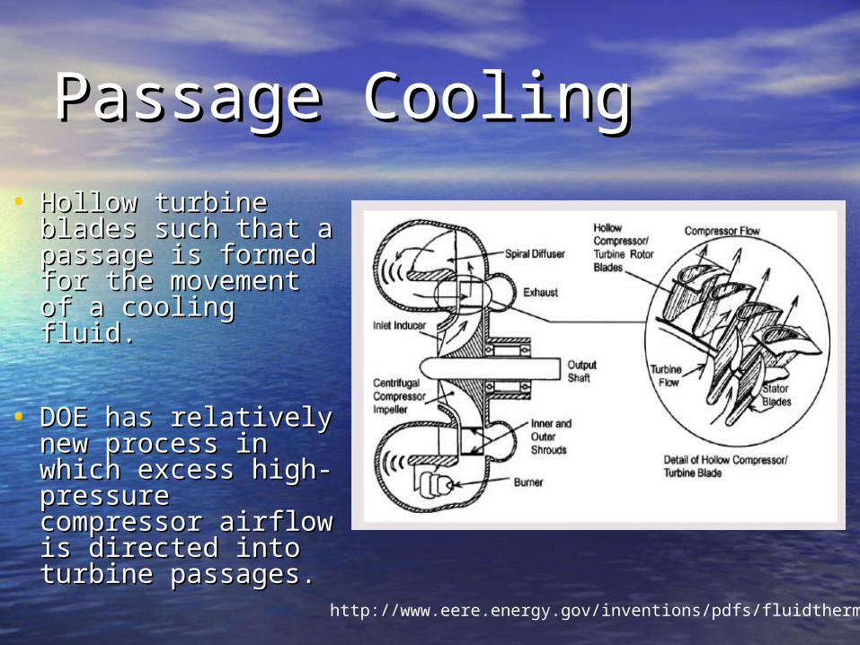
Passage CoolingPassage Cooling
• Hollow turbine Hollow turbine blades such that a blades such that a passage is formed passage is formed for the movement of for the movement of a cooling fluid. a cooling fluid.
• DOE has relatively DOE has relatively new process in new process in which excess high-which excess high-pressure pressure compressor airflow compressor airflow is directed into is directed into turbine passages.turbine passages.
http://www.eere.energy.gov/inventions/pdfs/fluidtherm.pdf
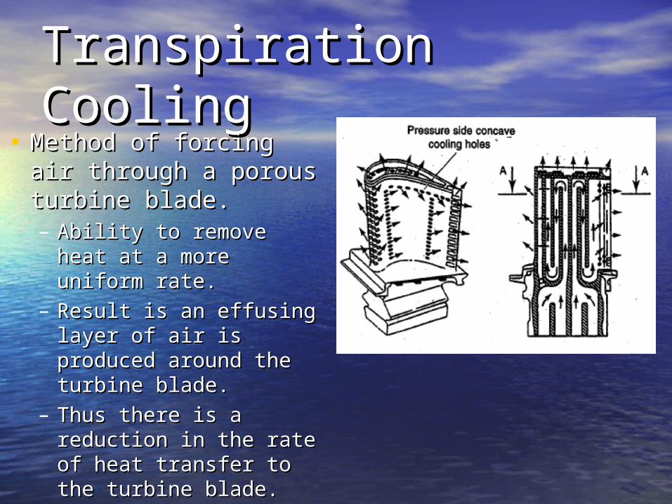
Transpiration CoolingTranspiration Cooling• Method of forcing air Method of forcing air
through a porous through a porous turbine blade. turbine blade. – Ability to remove heat Ability to remove heat
at a more uniform rate.at a more uniform rate.– Result is an effusing Result is an effusing
layer of air is produced layer of air is produced around the turbine around the turbine blade. blade.
– Thus there is a Thus there is a reduction in the rate of reduction in the rate of heat transfer to the heat transfer to the turbine blade. turbine blade.
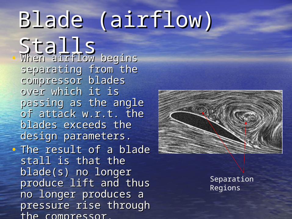
Blade (airflow) StallsBlade (airflow) Stalls• When airflow begins When airflow begins
separating from the separating from the compressor blades compressor blades over which it is passing over which it is passing as the angle of attack as the angle of attack w.r.t. the blades w.r.t. the blades exceeds the design exceeds the design parameters. parameters.
• The result of a blade The result of a blade stall is that the blade(s) stall is that the blade(s) no longer produce lift no longer produce lift and thus no longer and thus no longer produces a pressure produces a pressure rise through the rise through the compressor. compressor.
Separation Regions

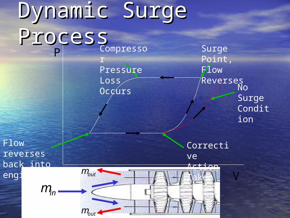
Dynamic SurgeDynamic Surge• Occurs when the static Occurs when the static
(inlet) air pressure rises past (inlet) air pressure rises past the design characteristics of the design characteristics of the compressor.the compressor.
• When there is a reversal of When there is a reversal of airflow from the compressor airflow from the compressor causing a surge to propagate causing a surge to propagate in the engine. in the engine.
• Essentially, the flow is Essentially, the flow is exhausted out of the exhausted out of the compressor, or front, of the compressor, or front, of the engine. engine.
• Result, is the compressor no Result, is the compressor no longer able to exhaust as longer able to exhaust as quickly as air is being drawn quickly as air is being drawn in and a “bang” occurs. in and a “bang” occurs. http://www.turbosolve.com/index.html
Compressor Inlet
Turbine Exit
Dynamic Surge EffectsDynamic Surge Effects• Cause: Inlet flow is reversedCause: Inlet flow is reversed
– Effect: Mass flow rate is reduced into engine.Effect: Mass flow rate is reduced into engine.– Effect: Compressor stages lose pressure.Effect: Compressor stages lose pressure.– Result: Pressure drop allows flow to reverse back Result: Pressure drop allows flow to reverse back
into engine. into engine. – Result: Mass flow rate increasesResult: Mass flow rate increases
• Cause: Increased mass flow causes high Cause: Increased mass flow causes high pressure again. pressure again. – Effect: Surge occurs again and process continues.Effect: Surge occurs again and process continues.– Result: Engine surges until corrective actions are Result: Engine surges until corrective actions are
taken.taken.
Dynamic Surge Dynamic Surge ProcessProcess
inmoutm
P
V
Surge Point, Flow Reverses
No Surge Condition
Compressor Pressure Loss Occurs
Flow reverses back into engine
Corrective Action Taken
outm
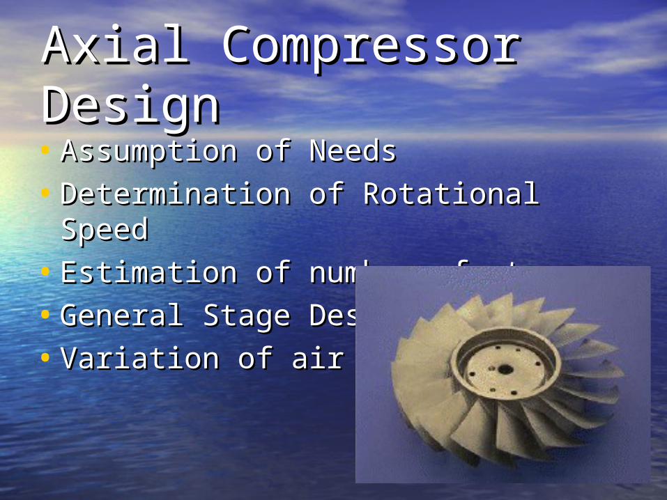
Axial Compressor Axial Compressor Design Design • Assumption of NeedsAssumption of Needs
• Determination of Rotational SpeedDetermination of Rotational Speed
• Estimation of number of stagesEstimation of number of stages
• General Stage DesignGeneral Stage Design
• Variation of air anglesVariation of air angles
Assumption of Needs Assumption of Needs • The first step in compressor design in The first step in compressor design in
the determination of the needs of the the determination of the needs of the systemsystem
• Assumptions:Assumptions:– Standard Atmospheric ConditionsStandard Atmospheric Conditions– Engine Thrust RequiredEngine Thrust Required– Pressure Ratio RequiredPressure Ratio Required– Air Mass Flow Air Mass Flow – Turbine inlet temperatureTurbine inlet temperature
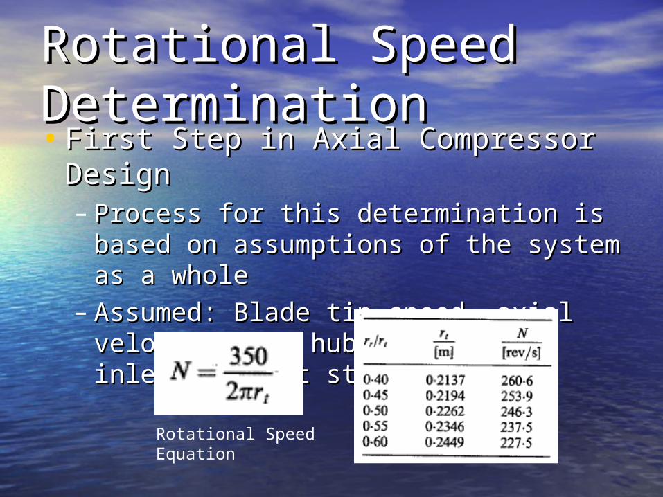
Rotational Speed Rotational Speed DeterminationDetermination• First Step in Axial Compressor DesignFirst Step in Axial Compressor Design
– Process for this determination is based Process for this determination is based on assumptions of the system as a on assumptions of the system as a wholewhole
– Assumed: Blade tip speed, axial Assumed: Blade tip speed, axial velocity, and hub-tip ratio at inlet to first velocity, and hub-tip ratio at inlet to first stage. stage.
Rotational Speed Equation
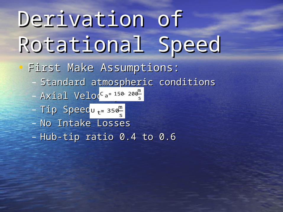
Derivation of Derivation of Rotational SpeedRotational Speed• First Make Assumptions:First Make Assumptions:
– Standard atmospheric conditionsStandard atmospheric conditions– Axial Velocity: Axial Velocity: – Tip Speed:Tip Speed:– No Intake LossesNo Intake Losses– Hub-tip ratio 0.4 to 0.6Hub-tip ratio 0.4 to 0.6
U t 350m
s
C a 150 200m
s

Compressor Rotational Compressor Rotational SpeedSpeed• Somewhat of an iterative process in Somewhat of an iterative process in
conjunction with the turbine design. conjunction with the turbine design. • Derivation Process:Derivation Process:
– First Define the mass flow into the First Define the mass flow into the systemsystem
– is the axial velocity range from the is the axial velocity range from the root of the compressor blades to the tips root of the compressor blades to the tips of the blades.of the blades.
AUmdot where U = 1aC
1aC
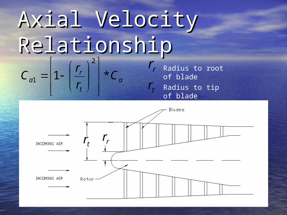
Axial Velocity Axial Velocity RelationshipRelationship
rr
at
ra C
r
rC *1
2
1
Radius to root of blade
rr
tr Radius to tip of blade
tr
Tip Radius Tip Radius DeterminationDetermination
2
11
2
1t
ra
dott
rr
C
mr
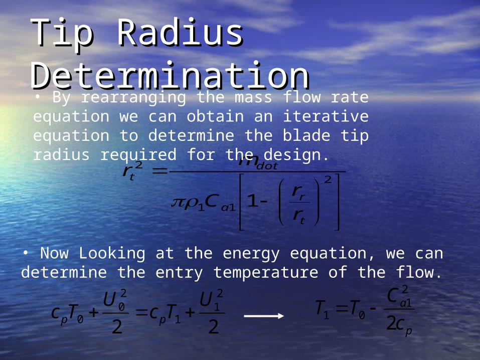
• By rearranging the mass flow rate equation we can obtain an iterative equation to determine the blade tip radius required for the design.
• Now Looking at the energy equation, we can determine the entry temperature of the flow.
p
a
c
CTT
2
21
01 22
21
1
20
0
UTc
UTc pp
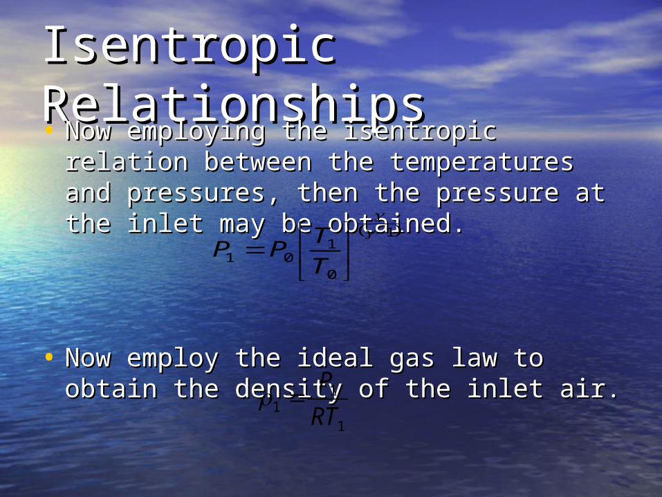
Isentropic Isentropic RelationshipsRelationships• Now employing the isentropic relation Now employing the isentropic relation
between the temperatures and pressures, between the temperatures and pressures, then the pressure at the inlet may be then the pressure at the inlet may be obtained.obtained.
• Now employ the ideal gas law to obtain Now employ the ideal gas law to obtain the density of the inlet air.the density of the inlet air.
1
0
101
T
TPP
1
11 RT
P
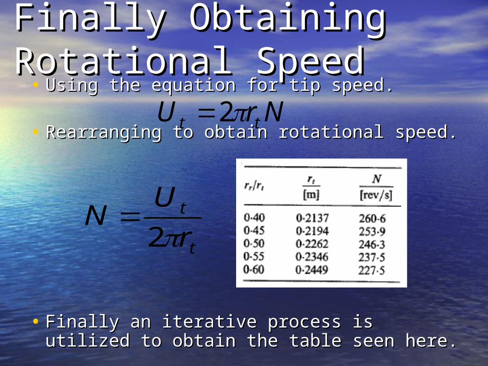
Finally Obtaining Finally Obtaining Rotational SpeedRotational Speed• Using the equation for tip speed.Using the equation for tip speed.
• Rearranging to obtain rotational speed.Rearranging to obtain rotational speed.
• Finally an iterative process is utilized to Finally an iterative process is utilized to obtain the table seen here.obtain the table seen here.
NrU tt 2
t
t
r
UN
2

Determining Number Determining Number of Stages of Stages • Make keen assumptionsMake keen assumptions
– Polytropic efficiency of approximately Polytropic efficiency of approximately 90%. 90%.
– Mean Radius of annulus is constant Mean Radius of annulus is constant through all stages. through all stages.
• Use polytropic relation to determine Use polytropic relation to determine the exit temperature of compressor.the exit temperature of compressor.
n
n
P
PTT
1
01
020102
n = 1.4, Ratio of Specific Heats, Cp/Cv
is the pressure that the compressor outputs
To1 is ambient temperature
02P
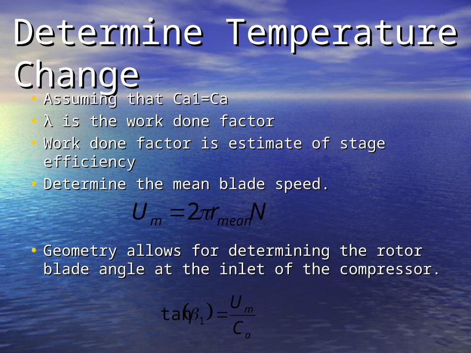
Determine Temperature Determine Temperature ChangeChange
• Assuming that Ca1=CaAssuming that Ca1=Ca
• λλ is the work done factor is the work done factor
• Work done factor is estimate of stage Work done factor is estimate of stage efficiencyefficiency
• Determine the mean blade speed.Determine the mean blade speed.
• Geometry allows for determining the rotor Geometry allows for determining the rotor blade angle at the inlet of the compressor.blade angle at the inlet of the compressor.
NrU meanm 2
a
m
C
U1tan
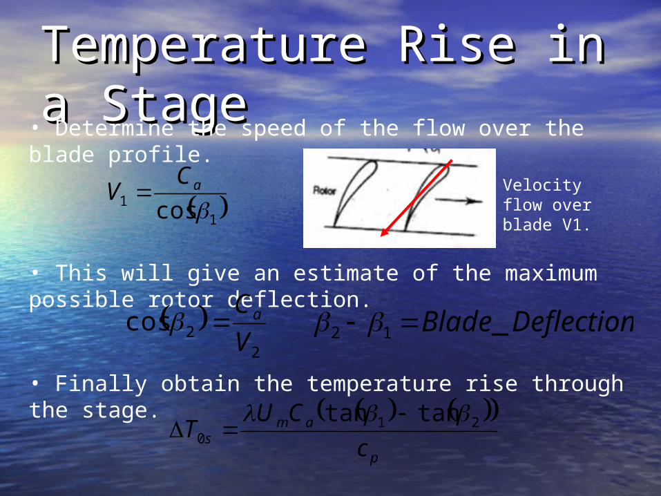
Temperature Rise in a Temperature Rise in a StageStage
p
ams c
CUT 210
tantan
11 cos aCV
• This will give an estimate of the maximum possible rotor deflection.
• Finally obtain the temperature rise through the stage.
2
2cosV
Ca
• Determine the speed of the flow over the blade profile.
Velocity flow over blade V1.
DeflectionBlade _12
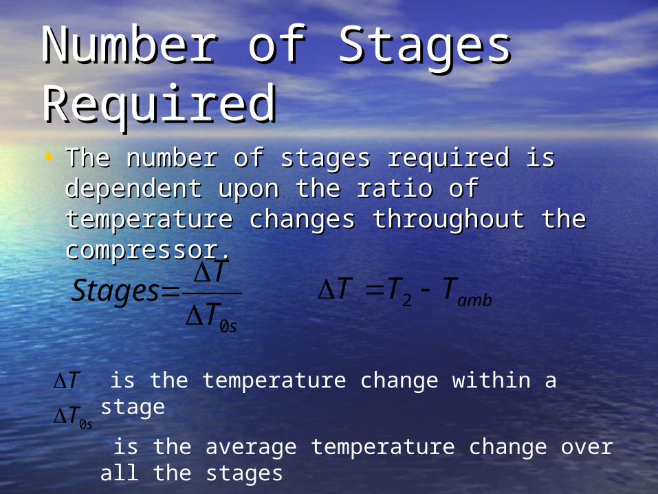
Number of Stages Number of Stages RequiredRequired• The number of stages required is The number of stages required is
dependent upon the ratio of temperature dependent upon the ratio of temperature changes throughout the compressor.changes throughout the compressor.
sT
TStages
0
ambTTT 2
is the temperature change within a stage
is the average temperature change over all the stages
sT
T
0

Designing a StageDesigning a Stage• Make assumptionsMake assumptions
– Assume initial temperature change Assume initial temperature change through first stage. through first stage.
– Assume the work-done factors through Assume the work-done factors through each stage. each stage.
– Ideal Gas at standard conditionsIdeal Gas at standard conditions
• Determine the air angles in each Determine the air angles in each stage. stage.
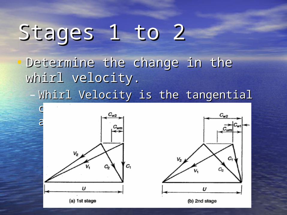
Stages 1 to 2Stages 1 to 2• Determine the change in the whirl Determine the change in the whirl
velocity.velocity.– Whirl Velocity is the tangential Whirl Velocity is the tangential
component of the flow velocity around component of the flow velocity around the rotor. the rotor.

Stage 1 to 2Stage 1 to 2• Change in whirl velocity through stage.Change in whirl velocity through stage.
12 www CCC
m
pw U
TcC
11 tan aw CC Alpha 1 is zero at the first stage.
a
w
a
wm
C
C
C
CU
22
22
tan
tan
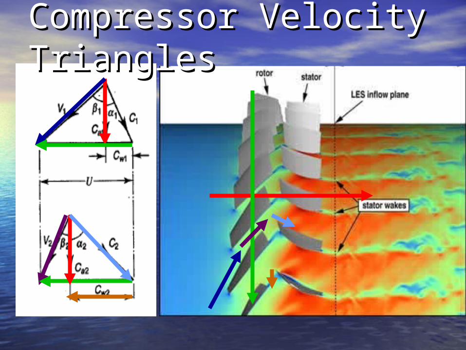
Compressor Velocity Compressor Velocity TrianglesTriangles

Pressure ratio of the Pressure ratio of the StageStage
10
01
03 1
amb
sss T
T
P
PR 9.0s
• The pressure ratio in the stage can be determined through the isentropic temperature relationship and the polytropic efficiency assumed at 90%.

Stage AttributesStage Attributes• The analysis shows that the stage can be outlined by the following attributes:
1.) Pressure at the onset of the stage.
2.) Temperature at the onset of the stage.
3.) The pressure ratio of the stage.
4.) Pressure at the end of the stage.
5.) Temperature at the end of the stage.
6.) Change in pressure through the stage. Example of a single
stage
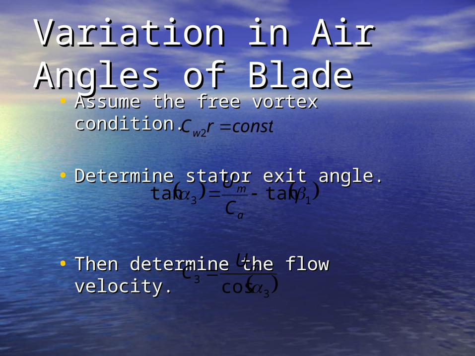
Variation in Air Angles Variation in Air Angles of Bladeof Blade
• Assume the free vortex condition. Assume the free vortex condition.
• Determine stator exit angle. Determine stator exit angle.
• Then determine the flow velocity. Then determine the flow velocity.
constrCw 2
13 tantan a
m
C
U
33 cos mUC

Air Angle TriangleAir Angle TriangleAlpha 1 is 0 at the inlet stage because there are no IGV’s.Thus, Ca1=C1, and Cw1 is 0Note: This
is the whirl velocity component and not a blade spacing!

Red is
Green is
Blue is
Velocity TriangleVelocity Triangle
aC
aC
aC
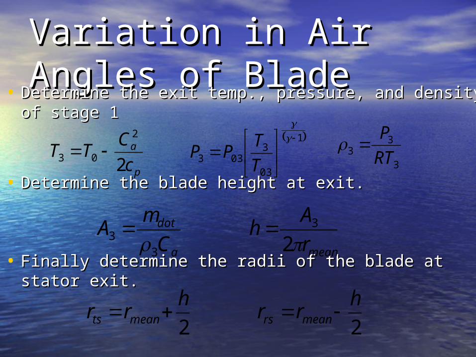
Variation in Air Angles Variation in Air Angles of Bladeof Blade
• Determine the exit temp., pressure, and density of Determine the exit temp., pressure, and density of stage 1stage 1
• Determine the blade height at exit.Determine the blade height at exit.
• Finally determine the radii of the blade at stator Finally determine the radii of the blade at stator exit.exit.
p
a
c
CTT
2
2
03 1
03
3033
T
TPP
3
33 RT
P
meanr
Ah
23
2
hrr meants
2
hrr meanrs
a
dot
C
mA
33
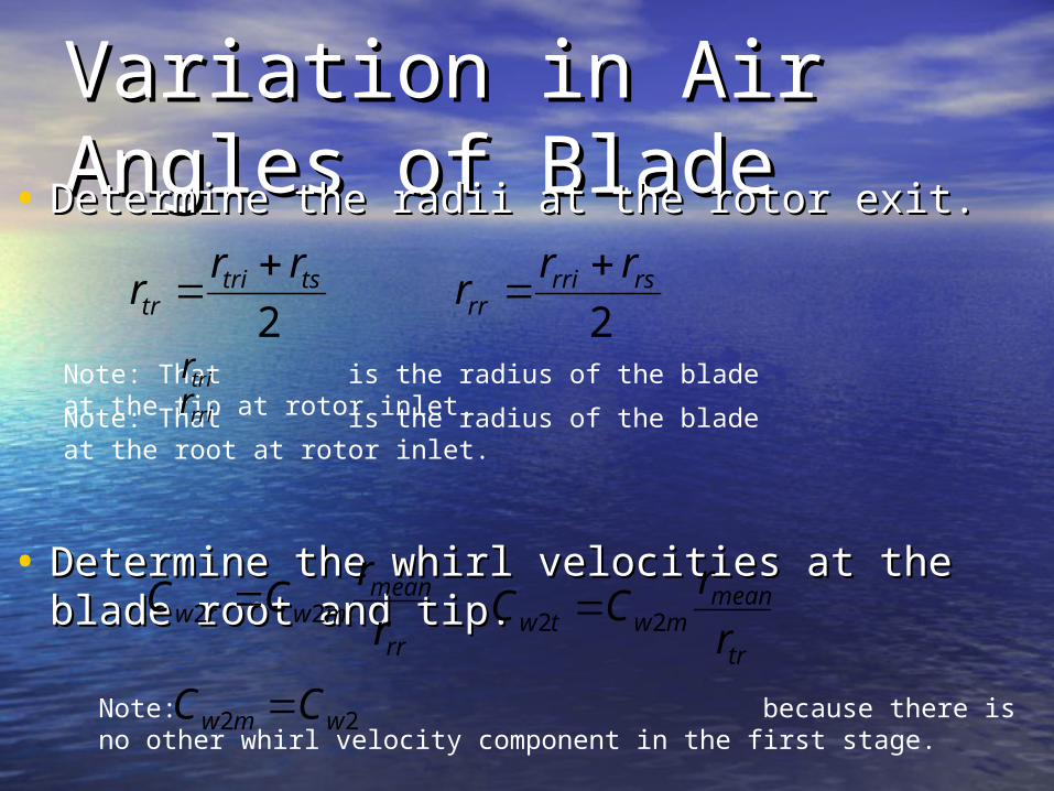
Variation in Air Angles Variation in Air Angles of Bladeof Blade• Determine the radii at the rotor exit.Determine the radii at the rotor exit.
• Determine the whirl velocities at the blade Determine the whirl velocities at the blade root and tip.root and tip.
2tstri
tr
rrr
2rsrri
rr
rrr
Note: That is the radius of the blade at the tip at rotor inlet.
trir
Note: That is the radius of the blade at the root at rotor inlet.
rrir
rr
meanmwrw r
rCC 22
tr
meanmwtw r
rCC 22
Note: because there is no other whirl velocity component in the first stage.
22 wmw CC
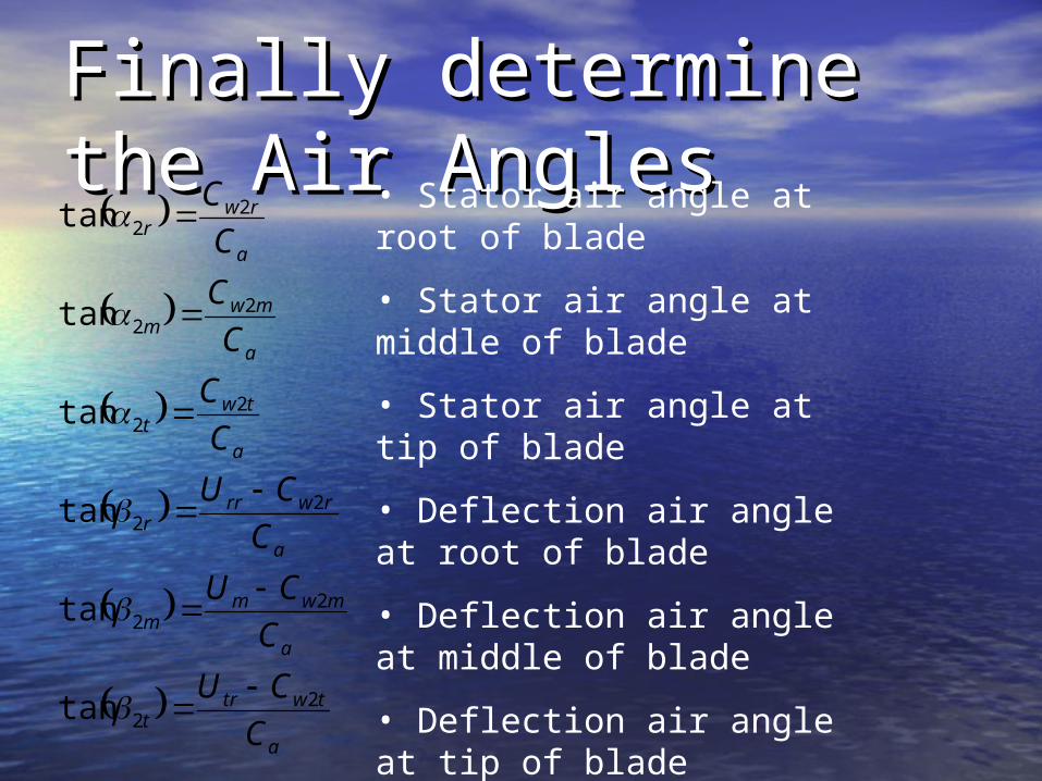
Finally determine the Air Finally determine the Air AnglesAngles
a
twtrt
a
mwmm
a
rwrrr
a
twt
a
mwm
a
rwr
C
CU
C
CU
C
CU
C
C
C
C
C
C
22
22
22
22
22
22
tan
tan
tan
tan
tan
tan
• Stator air angle at root of blade
• Stator air angle at middle of blade
• Stator air angle at tip of blade
• Deflection air angle at root of blade
• Deflection air angle at middle of blade
• Deflection air angle at tip of blade
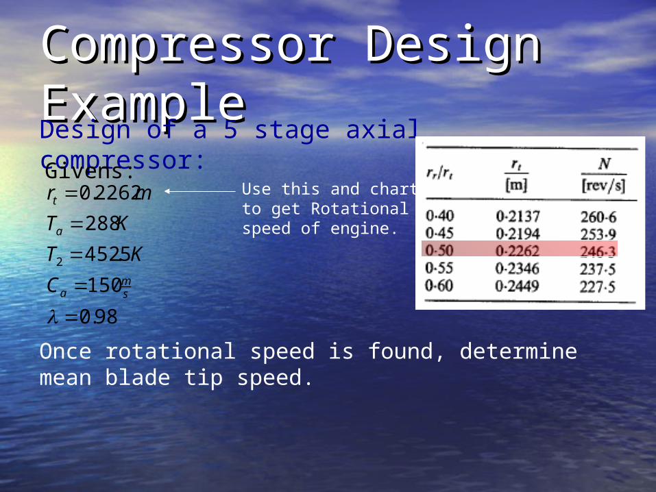
Compressor Design Compressor Design ExampleExampleDesign of a 5 stage axial compressor:
98.0
150
5.452
288
2262.0
2
sm
a
a
t
C
KT
KT
mrGivens:
Use this and chart to get Rotational speed of engine.
Once rotational speed is found, determine mean blade tip speed.
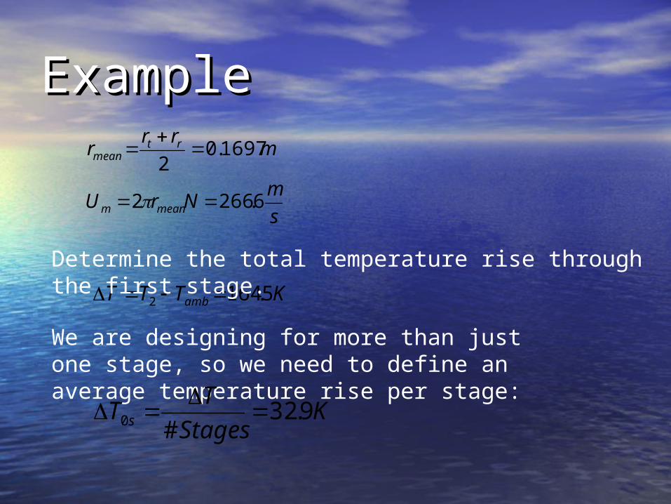
ExampleExample
s
mNrU
mrr
r
meanm
rtmean
6.2662
1697.02
KTTT amb 5.1642
Determine the total temperature rise through the first stage.
We are designing for more than just one stage, so we need to define an average temperature rise per stage:
KStages
TT s 9.32
#0
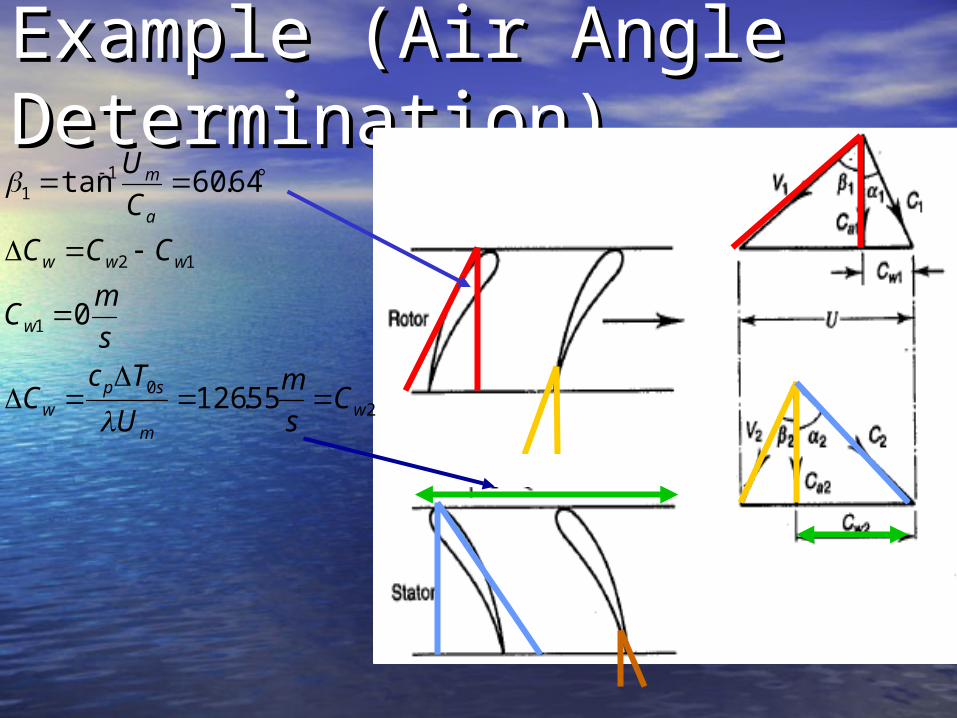
Example (Air Angle Example (Air Angle Determination)Determination)
20
1
12
11
55.126
0
64.60tan
wm
spw
w
www
a
m
Cs
m
U
TcC
s
mC
CCC
C
U
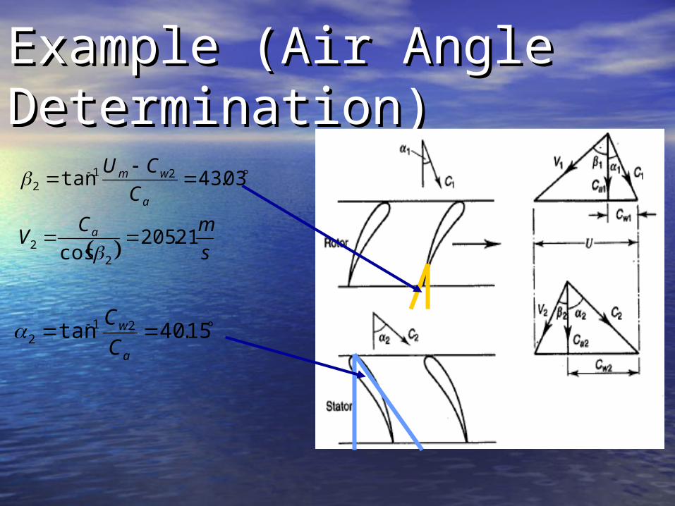
Example (Air Angle Example (Air Angle Determination)Determination)
s
mCV
C
CU
a
a
wm
21.205cos
03.43tan
22
212
15.40tan 212
a
w
C
C

Questions???Questions???