Turbidity and Suspended Solids Transmitter - mjk.com · GB 5.1 SuSix 071005 Data Sheet Turbidity...
6
GB 5.1 SuSix 071005 Data Sheet 5.1 Turbidity and Suspended Solids Transmitter We reserve the right to continuously improve our products and make any change in the stated specifications and dimensions without prior notice.
Transcript of Turbidity and Suspended Solids Transmitter - mjk.com · GB 5.1 SuSix 071005 Data Sheet Turbidity...
GB 5.1 SuSix 071005
TurbidityandSuspendedSolidsTransmitterDataSheet
5.1
TurbidityandSuspendedSolidsTransmitter
We reserve the right to continuously improve our products and make any change in the stated specifications and dimensions without prior notice.
GB 5.1 SuSix 071005
TurbidityandSuspendedSolidsTransmitterDataSheet
2
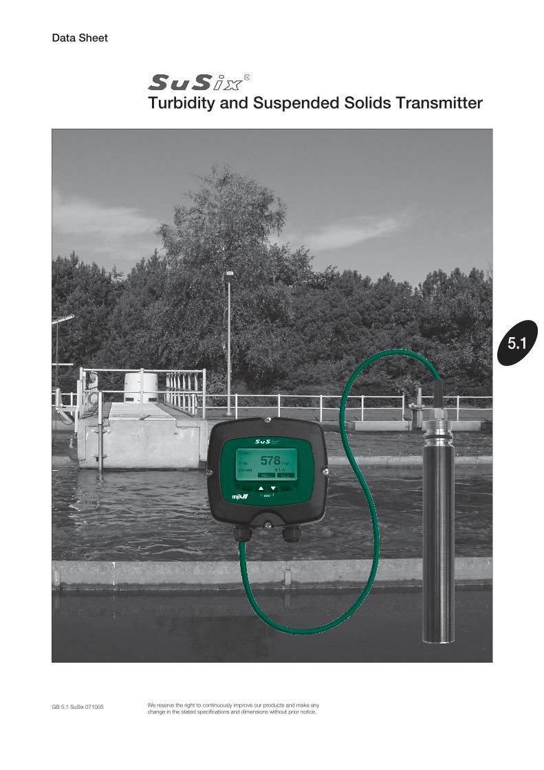
General MJK SuSix® turbidity and suspended solids sensors are designed for measurement by immersing the sensor into open tanks, wells and containers or in-line pipe mounting.
The SuSix® transmitter is rugged and de-signed to handle tough applications.
The scratch-proof saphire optics, the PUR cable and the heavy duty sensor housing ensure long life, even where scaling and bio-fouling are problems.
Applications
The sensor provides a full range from 0.001 to 9999 FNU/NTU for turbidity and 0.001 to 400 g/l (SiO2) for suspended solids measure-ments. The turbidity measurement complies with ISO 7027.
The SuSix® is equipped with beam forming optics for multi-angle detection of turbidity and suspended solids. This advanced optical system is combined with a progressive algo-rithm using neural logic to generate a reliable high quality measurement.
The sensor compensates for errors due to fouling or aging of the optical array and com-pensates for gas bubbles in the sample.
The SuSix® sensor is provided with factory calibration for turbidity, and zero point fac-tory calibration for suspended solids.
A single point in-situ calibration can be conducted for many applications. For more rigorous or difficult applications a two- or three-point calibration is also possible.
Sewage and wastewater plants
Drinking water
Biologic control
•
•
•
Calibration
OneSensor-FullRange
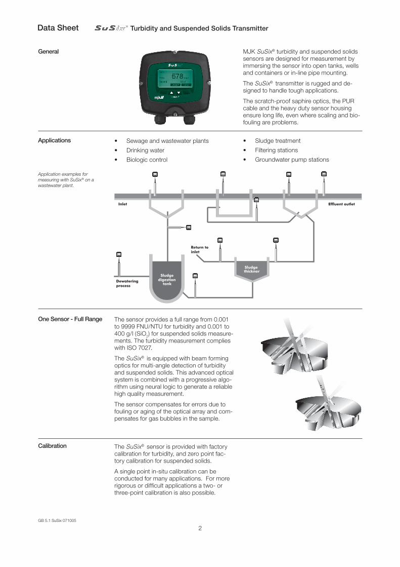
Inlet Aerationbasin
Sludgethickner
Sludgedigestion
tank
ClarifierPreclarifier Effluent outlet
Return toinlet
Dewateringprocess
Application examples for measuring with SuSix® on a wastewater plant.
Sludge treatment
Filtering stations
Groundwater pump stations
•
•
•
GB 5.1 SuSix 071005
TurbidityandSuspendedSolidsTransmitterDataSheet
3
HighQualityMaterials
PCConnection
SimpletoOperate
FlexibleInstallation
FlexibleIn-andOutputs
User-definableText
Modbus®
Communication
llRS-485
RS-485
RS-485
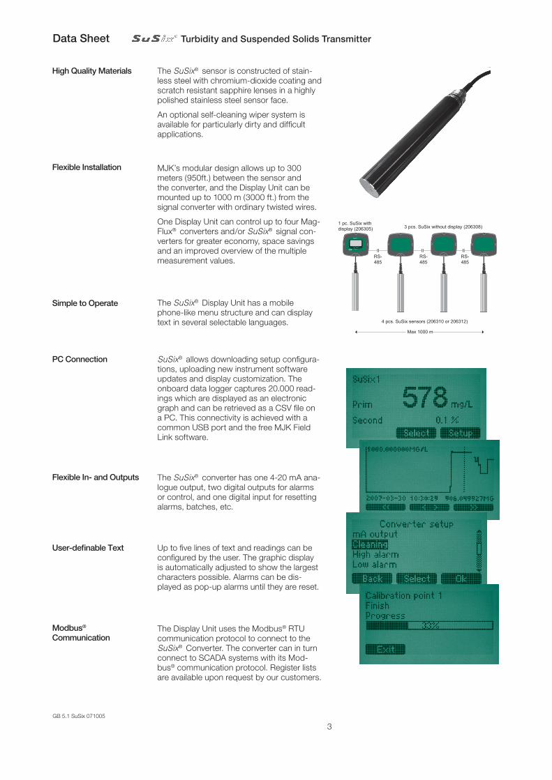
Max 1000 m
1 pc. SuSix withdisplay (206305) 3 pcs. SuSix without display (206308)
4 pcs. SuSix sensors (206310 or 206312)
ll ll
The SuSix® sensor is constructed of stain-less steel with chromium-dioxide coating and scratch resistant sapphire lenses in a highly polished stainless steel sensor face.
An optional self-cleaning wiper system is available for particularly dirty and difficult applications.
MJK’s modular design allows up to 300 meters (950ft.) between the sensor and the converter, and the Display Unit can be mounted up to 1000 m (3000 ft.) from the signal converter with ordinary twisted wires.
One Display Unit can control up to four Mag-Flux® converters and/or SuSix® signal con-verters for greater economy, space savings and an improved overview of the multiple measurement values.
SuSix® allows downloading setup configura-tions, uploading new instrument software updates and display customization. The onboard data logger captures 20.000 read-ings which are displayed as an electronic graph and can be retrieved as a CSV file on a PC. This connectivity is achieved with a common USB port and the free MJK Field Link software.
The SuSix® Display Unit has a mobile phone-like menu structure and can display text in several selectable languages.
The SuSix® converter has one 4-20 mA ana-logue output, two digital outputs for alarms or control, and one digital input for resetting alarms, batches, etc.
The Display Unit uses the Modbus® RTU communication protocol to connect to the SuSix® Converter. The converter can in turn connect to SCADA systems with its Mod-bus® communication protocol. Register lists are available upon request by our customers.
Up to five lines of text and readings can be configured by the user. The graphic display is automatically adjusted to show the largest characters possible. Alarms can be dis-played as pop-up alarms until they are reset.
GB 5.1 SuSix 071005
TurbidityandSuspendedSolidsTransmitterDataSheet
4
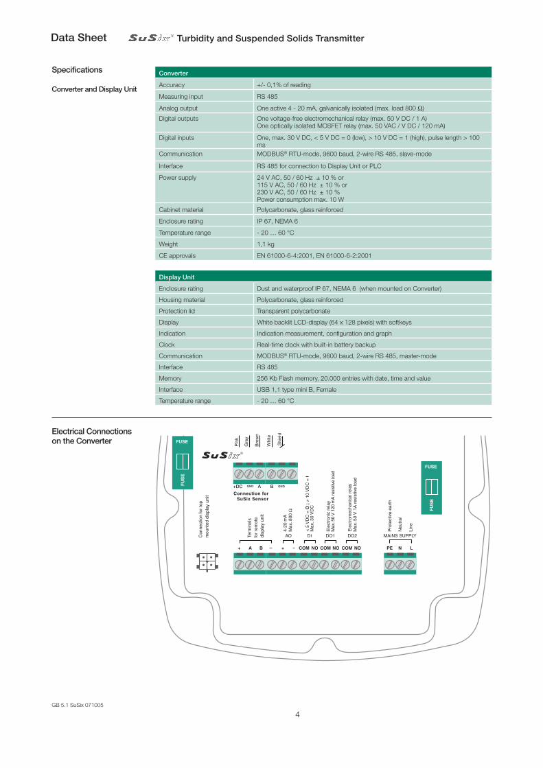
Specifications
ConverterandDisplayUnit
Converter
Accuracy +/- 0,1% of reading
Measuring input RS 485
Analog output One active 4 - 20 mA, galvanically isolated (max. load 800 W)
Digital outputs One voltage-free electromechanical relay (max. 50 V DC / 1 A) One optically isolated MOSFET relay (max. 50 VAC / V DC / 120 mA)
Digital inputs One, max. 30 V DC, < 5 V DC = 0 (low), > 10 V DC = 1 (high), pulse length > 100 ms
Communication MODBUS® RTU-mode, 9600 baud, 2-wire RS 485, slave-mode
Interface RS 485 for connection to Display Unit or PLC
Power supply 24 V AC, 50 / 60 Hz ± 10 % or115 V AC, 50 / 60 Hz ± 10 % or230 V AC, 50 / 60 Hz ± 10 % Power consumption max. 10 W
Cabinet material Polycarbonate, glass reinforced
Enclosure rating IP 67, NEMA 6
Temperature range - 20 … 60 °C
Weight 1,1 kg
CE approvals EN 61000-6-4:2001, EN 61000-6-2:2001
ElectricalConnectionsontheConverter
Pin
k
Connection forSuSix Sensor
Gre
y
Bro
wn
Whi
te
Shi
eld
+DC GNDA BGND
Line
disp
lay
unitdisp
lay
unit
DisplayUnit
Enclosure rating Dust and waterproof IP 67, NEMA 6 (when mounted on Converter)
Housing material Polycarbonate, glass reinforced
Protection lid Transparent polycarbonate
Display White backlit LCD-display (64 x 128 pixels) with softkeys
Indication Indication measurement, configuration and graph
Clock Real-time clock with built-in battery backup
Communication MODBUS® RTU-mode, 9600 baud, 2-wire RS 485, master-mode
Interface RS 485
Memory 256 Kb Flash memory, 20.000 entries with date, time and value
Interface USB 1,1 type mini B, Female
Temperature range - 20 … 60 °C
GB 5.1 SuSix 071005
TurbidityandSuspendedSolidsTransmitterDataSheet
5
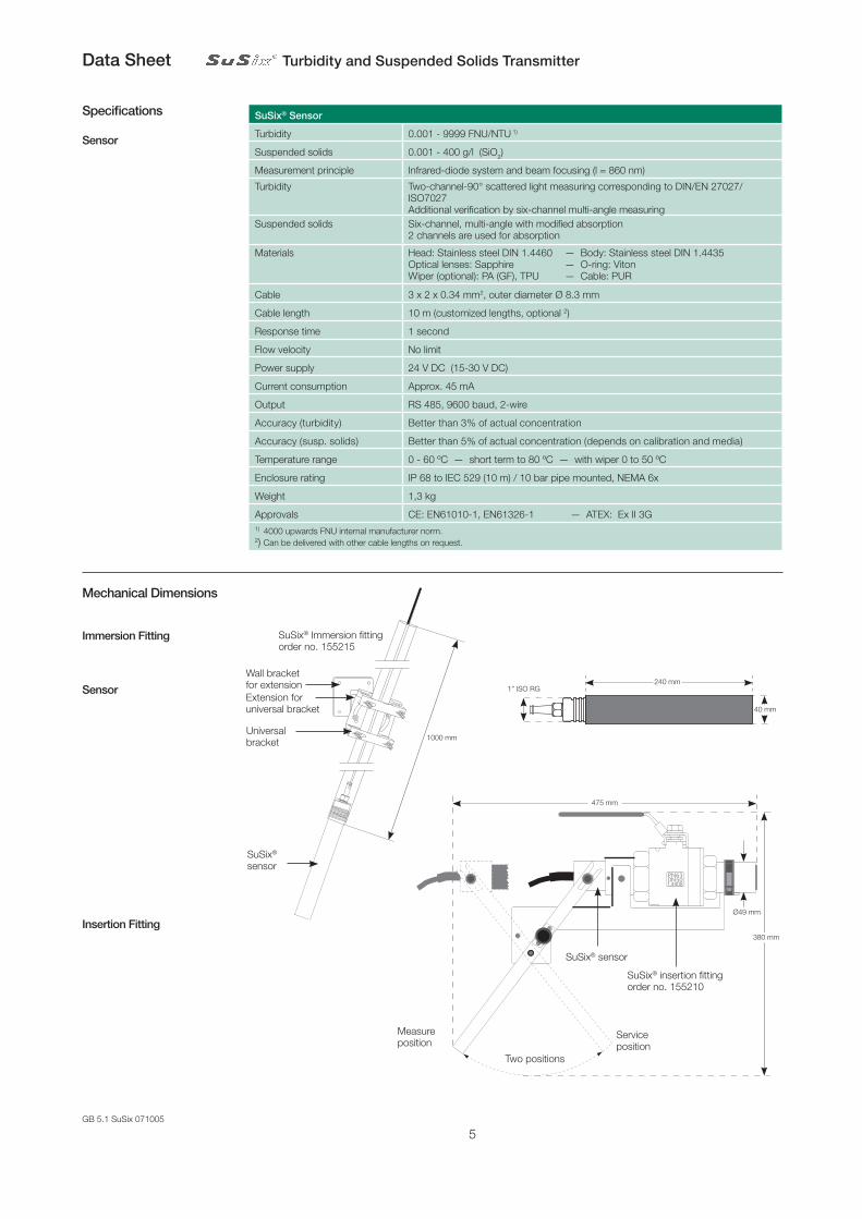
Specifications
Sensor
SuSix®Sensor
Turbidity 0.001 - 9999 FNU/NTU 1)
Suspended solids 0.001 - 400 g/l (SiO2)
Measurement principle Infrared-diode system and beam focusing (l = 860 nm)
Turbidity Two-channel-90° scattered light measuring corresponding to DIN/EN 27027/ISO7027 Additional verification by six-channel multi-angle measuring
Suspended solids Six-channel, multi-angle with modified absorption2 channels are used for absorption
Materials Head: Stainless steel DIN 1.4460 — Body: Stainless steel DIN 1.4435Optical lenses: Sapphire — O-ring: VitonWiper (optional): PA (GF), TPU — Cable: PUR
Cable 3 x 2 x 0.34 mm2, outer diameter Ø 8.3 mm
Cable length 10 m (customized lengths, optional 2)
Response time 1 second
Flow velocity No limit
Power supply 24 V DC (15-30 V DC)
Current consumption Approx. 45 mA
Output RS 485, 9600 baud, 2-wire
Accuracy (turbidity) Better than 3% of actual concentration
Accuracy (susp. solids) Better than 5% of actual concentration (depends on calibration and media)
Temperature range 0 - 60 ºC — short term to 80 ºC — with wiper 0 to 50 ºC
Enclosure rating IP 68 to IEC 529 (10 m) / 10 bar pipe mounted, NEMA 6x
Weight 1,3 kg
Approvals CE: EN61010-1, EN61326-1 — ATEX: Ex II 3G1) 4000 upwards FNU internal manufacturer norm.2) Can be delivered with other cable lengths on request.
MechanicalDimensions
ImmersionFitting
SuSix® sensor
Wall bracket for extension
SuSix® Immersion fittingorder no. 155215
1000 mm
Extension for universal bracket
Universal bracket
Sensor
T
SuSix® sensor
SuSix® insertion fittingorder no. 155210
Serviceposition
Measureposition
Two positions
475 mm
380 mm
Ø49 mm
InsertionFitting
240 mm1” ISO RG
40 mm
GB 5.1 SuSix 071005
TurbidityandSuspendedSolidsTransmitterDataSheet
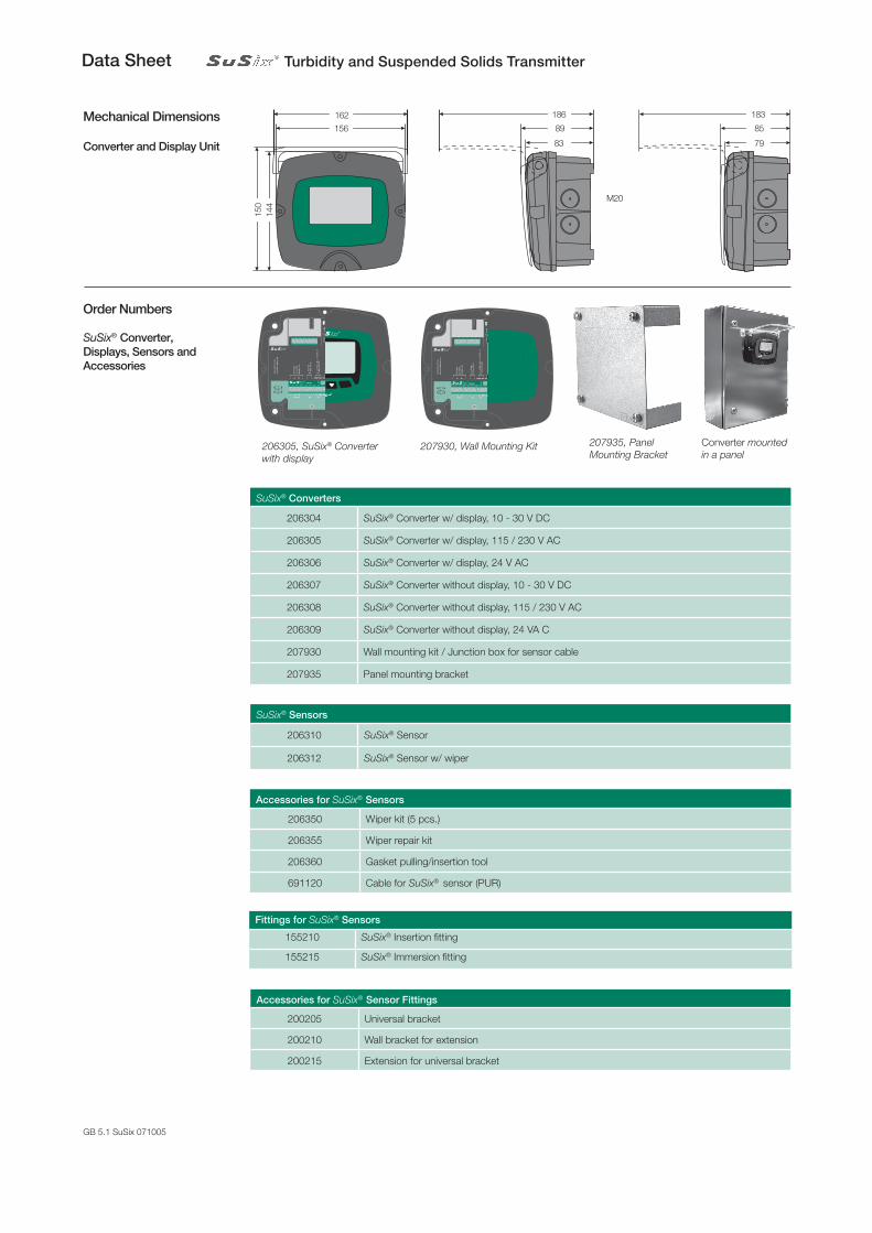
OrderNumbersSuSix® Converter,Displays,SensorsandAccessories
SuSix®Converters
206304 SuSix® Converter w/ display, 10 - 30 V DC
206305 SuSix® Converter w/ display, 115 / 230 V AC
206306 SuSix® Converter w/ display, 24 V AC
206307 SuSix® Converter without display, 10 - 30 V DC
206308 SuSix® Converter without display, 115 / 230 V AC
206309 SuSix® Converter without display, 24 VA C
207930 Wall mounting kit / Junction box for sensor cable
207935 Panel mounting bracket
AccessoriesforSuSix® Sensors
206350 Wiper kit (5 pcs.)
206355 Wiper repair kit
206360 Gasket pulling/insertion tool
691120 Cable for SuSix® sensor (PUR)
Converter mounted in a panel
207935, Panel Mounting Bracket
Mainssupply
-mA- -D02--D01--DI--Display-+ +A B C2 N02C NO N01 PE N L- -
+DC GND A B
Pin
k
Gre
y
Bro
wn
Shi
eld
5212
69
C1
Line
2 wire shielded cable.
4 wire shielded cable.
Fus
e 24
V A
C: 5
00m
A T
Fus
e 11
5V A
C: 1
25m
A T
Fus
e 23
0V A
C: 6
3mA
T
disp
lay
unitdisp
lay
unit
Display unitConverter #4Converter #1
Max. four MJK converters with Modbuscan be connected to one display unit:
5212
68
207930, Wall Mounting Kit
Mainssupply
-mA- -D02--D01--DI--Display-+ +A B C2 N02C NO N01 PE N L- -
+DC GND A B
Pin
k
Gre
y
Bro
wn
Shi
eld
5212
69
C1
Line
2 wire shielded cable.
4 wire shielded cable.
Fus
e 24
V A
C: 5
00m
A T
Fus
e 11
5V A
C: 1
25m
A T
Fus
e 23
0V A
C: 6
3mA
T
disp
lay
unitdisp
lay
unit
Display unitConverter #4Converter #1
Max. four MJK converters with Modbuscan be connected to one display unit:
5212
68
206305, SuSix® Converter with display
SuSix®Sensors
206310 SuSix® Sensor
206312 SuSix® Sensor w/ wiper
FittingsforSuSix®Sensors
155210 SuSix® Insertion fitting
155215 SuSix® Immersion fitting
AccessoriesforSuSix® SensorFittings
200205 Universal bracket
200210 Wall bracket for extension
200215 Extension for universal bracket
MechanicalDimensions
ConverterandDisplayUnit
150
144
162
156
M20
186
89
83
183
85
79