Tunnel Logic Manual - Auto Data - Home
79
1 Tunnel Logic User’s Guide __________________________________________ Copyright ©2017 Auto Data Inc. Website: http://www.autodatainc.com
Transcript of Tunnel Logic Manual - Auto Data - Home

1
Tunnel Logic User’s Guide
__________________________________________
Copyright ©2017 Auto Data Inc.
Website: http://www.autodatainc.com


3
Table of Contents
CHAPTERS
SECTION ONE – PROGRAM SETUP
1 Wash Configuration……..……………………………………………………….…………...………………………………………………………..…………………………………………………….…5 2 Inputs…………………………………………………………………………………………………..……..……………………………..…………………..…………………………………………………….……………..7 3 Outputs……………………………………………………………………………………………………..……………………………….…………………..………………………………………………….……………..9 4 Wash Packages Setup……..…………………………………………………………………………..…………………………………………………………………………….…………..……..13 5 Add-On's……………………………………………..……………………………………………..….……..………………..….……………………………..……………………….………………………....………15 6 Override Options………..…………….………...…………………………………………………..………………..……………………….……..……………………………….…………….……………17 7 Miscellaneous Menu…………....…………..…………………………………………..……….……..………………..……………….…………..……….……………………………….....……......19 8 Tunnel Logic Reports……..……….……………………………………………….……………….……………..……………………………………………………………………………………....23 9 Setup Options………..………………………………..….…………………………………………………….……..………………..………….……..……………………………….…………….……….......25
SECTION TWO – TOUCH BUTTON STATION
10 Touch Button Station Introduction.…………………………………….…………..….……………..……..…………….……………..………..………………………………...29 11 Building the Customer Queue………...……………………………………..…..……………………………………..……..…………….……………..……………….……………..31 12 Initiating a Wash………...……………………..…….………………………………………….…………………………..……..……………..…………………………………………….……………..33 13 Car Wash Sales Data…………………………………………………………………………………………..……..……….…….……….………….……………………………..…………......35 14 View Setup…………………………..……..……………………………………………..……………………..……..…………….……….……………………………..…………………………………….…..37
Inputs and Outputs…………………………………..……………………..……………………………………..…………….…………...…………………………………..…..….....38 Auto Control Settings……………………………..………………………………………………….……………………….…………...………………………………....………......39 Gates………………………………….………………………..………………………………………………….……………………….…………...………………………………....………......40
15 Emergency Stop….……………..………….…..…………………………………………..…………….………..……………….…….……….……………….……..…………………….……………..41 16 System Stop Conditions.……….……………………………………………….……..…..…..…………….………………..………..……..……….……..…………………….……………..43 17 Car Wash Printers…………..……….………..……..……...………………………………………….…….………………………….…………………………….…………………….……………..45
SECTION THREE – HTK 18 Configuring HTK…………..………………..…………………….………………………………..……………..………………………..………………………………….………….…….…………..47
How to access 'service mode'…………..……………………..…………………………….…………………………………….…………...…..........................................51
HTK Network Settings……………..……………………..…………………………….…………………………………….…………...…………………………………..…..…..52 Setting up a User……………..…………………………………………...……………..……………………………………….…………...…………………………………..…..…..58 Set up Dan/Aux………………………………………………………………………………………………………………………………………………………………......................60 Queue Settings……………………..…………………………………....………………..……………………………………….…………...…………………………………..….........65 Configuring Terminal Settings…..…………………………………………...……………..…………………..…………………………………....…………...…………......67 Barcode Setup………………..…..…………………………………………...……………..…………………..……………………………….…...…………...…………......70
APPENDIX A Outputs Worksheet…………………..…………………………….…………………………………….…………...…………………………………………………………………………...….……73

4

5
CHAPTER 1 : Wash Configuration To navigate to the wash configuration menu, click on the WASH tab. Be sure to save your changes often to ensure no data is lost in case of a communication error! To save your
changes, click the Save button located throughout the screens. Note: If you try to save an output while the
conveyor is running, you will get a message indicating the tunnel is in use. You will be allowed to save the
output even if the conveyor is running.
Figure 1-1
When you click on any icon on the WASH tab screen, you will be prompted to enter a password. Once you
enter your password, the computer will connect to the Tunnel Logic car wash controller's PLC
(Programmable Logic Controller) and read its current settings. If the computer is not able to detect the tunnel controller on the local network, it will give the option of
connecting over the Internet. If you decide to connect over the Internet, you will need to enter the site number
for the location you wish to connect to. See Chapter 10 “Remote Access” for more information on connecting
remotely. When you exit the WASH tab screen, you will be asked if you want to save your changes. If you click
YES, your tunnel controller will be updated. If you click NO, you will exit without saving changes. Don’t
forget to save your changes often to avoid losing data in case of a communication error. HOW TO: Setup your system Before adding wash packages into your system, you will need to configure your outputs. Auto Data
recommends wiring your outputs first in your controller and then going into the outputs section of the WASH
tab and configuring them according to your hardware wiring. 1. Wire your inputs and outputs. 2. Print a blank Outputs Worksheet from the Miscellaneous menu. See Appendix A for sample worksheet. 3. Configure your outputs based on the information collected about outputs, such as distances measured,
output types and output descriptions. 4. Print out another copy of the Outputs Worksheet, after configuring your outputs, and keep for your
records. 5. Configure your setup options in the Miscellaneous menu. 6. Program your wash packages, add-on's (a-la-carte items) and overrides. 7. Configure wet down settings.

6

7
CHAPTER 2 : Car Wash Inputs Auto Data requires all inputs to be sourcing inputs. For the photo eye, input is expected to be ON
always, except when photo eye beam is broken. To configure inputs in Pos-I -Lube, go to the Miscellaneous menu and then select INPUTS. Inputs 0-15
are reserved for common input types and must be wired as follows:
0. Emergency Stop 1. Entry Photo Eye 2. Pulse Switch 3. Anti-Collision 4. Wash Start Button 5. Roller Counter 6. Axle Locator – Will count every time a tire passes this sensor. If the tire counter is not zero at
closing, the tire total will be displayed on reports. 7. Auto Load
8 -15. Dry Contact Auto Cashier inputs 28-31. Gate Control
Inputs 16-27 are user-defined and may include any of the following input types.
Figure 2-1
Critical Fault– When a critical fault occurs, the conveyor will be stopped. For more information on this type of
input, see Chapter 18 “System Stop Conditions”. Examples of critical faults include: • Low Oil • Low Air • Entry Door Closed
Warning Fault – If a warning fault occurs, a warning message will appear on the touch button station,
alerting of the problem, but the equipment will continue to operate. An example of a condition that would
trigger a warning fault would be low soap. Manual– Manual Inputs are optional and may include physical buttons mounted at the tunnel location to
manually activate equipment, such as: • Prep Gun Switches • Wet Down Start Button • Send Hot Roller Button

8
Anti-Collision Approach (Optional) Second anti-collision sensor located near end of
tunnel. This sensor will indicate if a car is approaching, while the first sensor, located at end
of tunnel will indicate if a car is at the end of the tunnel. If both conditions are met, the
conveyor will stop. Pickup Truck Sensor – This sensor will indicate if the vehicle entering the tunnel is a pickup
truck. If it is, the settings that have been configured for a pickup truck override will
automatically be applied to the wash.
High Hood Sensor - This sensor will indicate if the hood of a vehicle is square and high than
a normal hood. If it is, the settings that have been configured for a high hood override will
automatically be applied to the wash.
Contact Default Setting - For all inputs that are user-defined, the contact must be set to
either Normally OPEN or Normally CLOSED. Normally OPEN indicates this input is always
OFF and if it turns ON an action should be taken. Normally CLOSED indicates the input
is always ON and if it turns OFF, an action should be taken. Normally OPEN is the default
setting.

9
CHAPTER 3 : Outputs Outputs are used by the controller to turn equipment in the tunnel on and off. Auto Data recommends first wiring your outputs and then configuring them in the Output configuration menu.
To assist with entering your output settings, first print your Outputs Worksheet (See sample in Appendix A)
by going to the Outputs section of the Wash tab and clicking Print. Once the worksheet is displayed, click
Print All Pages.
Figure 3-1
Types of Outputs The following output types are pre-defined in the system and will be found in your drop-down list in the
outputs screen. Any output that you program in the system will fall into one of these types. • Full - Output will be active for the full length of the car. • Front Bumper Only - Output will only operate for the front portion of the car. • Rear Bumper Only - Output will only operate for the rear portion of the car. • Dryer / Blower - Drying device will operate for the full length of the car. • Tire Device - Will operate when a tire passes. Example: Wheel washers. • Retract (Full Car) - Will retract the selected output as the vehicle passes. • Retract (Front Bumper)- Will retract the selected outputs for the front bumper of the car. • Door Entrance and Door Exit • Prep Guns #1,2 - Timed outputs for manually applying pre-wash chemicals. • Anti-Collision Teach - Anti-Collision sensor calibration. • Anti-Collision Sign - Sign at the end of tunnel to alert customer their wash is complete and they
should move forward. Sign turns off automatically when vehicle has left the collision zone.
• Entrance Sign - Sign at tunnel entrance to display type of wash selected. Turns on when wash
started and off when car passes entry photo eye.
• Conveyor • Roller Up - Sends roller to push vehicle through wash. • Warning Horn - Buzzer sounded prior to conveyor startup. • Run with Conveyor – Output will operate whenever the conveyor is running. This option is not available
for testing and calibration sensors. This output will not activate if in test mode. • Entrance Forward Sign – Output will activate when vehicle is added to the queue. • Entrance Stop Sign – Output will activate when vehicle reaches auto load switch and will stay active
for five seconds.
• Entrance Neutral Sign – Output will activate when Entrance Stop Sign turns off and will stay active
until vehicle breaks photo eye. • Manual –The output can only be activated manually from the touch button station. • POS Go Sign – Output at the beginning of the tunnel that will activate when it is clear for a car to enter. • Wash Code OK Sign – Output that activates once a wash code has been scanned. • Exit Door Open/Closed Sign – Output at the end of the tunnel that will activate when a car can exit the
tunnel.

10
Full Car Output and Dryer Output With a full car output, enter the distance, in inches, from the entry photo eye to the beginning of the
equipment station. To activate this output before the vehicle arrives at the station, enter the number of inches
in the ON field. If you would like this output to stay active after the vehicle passes, enter the number of inches
in the OFF field. For large equipment stations, such as mitters or wraps, add the length of the equipment station to the OFF
distance.
Figure 3-2
Look Ahead parameter - The Look Ahead parameter will keep the current output ON, for example a dryer, if
it 'sees' another car within the Look Ahead distance. This may help extend the life of the equipment and also
cut back on energy cost, since the dryer will not need to stop and re-start with each vehicle. ON during AntiCollision parameter – This option allows the current output to stay ON in case the conveyor
stops to prevent a collision. Only outputs that will not damage cars if they remain on, such as dryers, should
have this option set to “Y”, for yes. Normally Open, Normally Closed parameter (N/O, N/C) – Indicates whether, in normal conditions,
the contact for this output is normally open or normally closed. Pickup Truck – This parameter may only be used with the Full Car, Retract, and Dryer / Blower outputs. To
configure, click on Pickup Truck button and then select whether you would like the output to operate for the FULL LENGTH, CAB ONLY, or BED ONLY of the truck. The default setting is NONE OF THE ABOVE.
Figure 3-3 Figure 3-4

11
Front Bumper Only Output For front bumper outputs, you can activate the output before the vehicle arrives at the station and specify
how long it should remain active after the bumper passes by adjusting the ON and OFF distances. You will
also need to enter the distance for the entry photo eye to the front of this station.
Figure 3-5
Rear Bumper Only Output For rear bumper outputs, you can specify how far in advance of the rear bumper the output should activate,
by entering a value in the ON distance. To set the distance the output should remain active after the vehicle
has passed the station, enter a value in the OFF distance. You will also need to enter the distance from the
entry photo eye to the beginning of this station.
Figure 3-6

12
Retract Output
If you would like a piece of equipment to retract for certain vehicles, you can use the Retract output.
For example, if you would like tire brushes to retract to prevent damage to vehicle aftermarket
wheels, you can create a Tire Brush Retract output, with type Retract, then when the corresponding
override is initialized, the tire brushes will retract as the vehicle passes. The setup parameters for
this type of output are the same as the Full Car output type.
Figure 3-7
Prep Gun Outputs Prep Gun outputs can be configured to operate for a specified amount of time. Enter the amount of
time you would like this output to operate in the Timeout field.
Tire Device Output Tire Device outputs are used to apply chemicals or activate equipment specifically to tires. This
output type is dependent upon a tire treadle switch, located at the tunnel entrance, to determine the
location of the tires relative to the vehicle front bumper. Note that the treadle is only active when the
entry photo eye beam is broken by the vehicle and thus must be located 12 inches from the photo
eye. The parameters required for this output type are the distance from the tire application station
to the tire treadle, and the ON and OFF distances to adjust output activation.
Figure 3-8
13
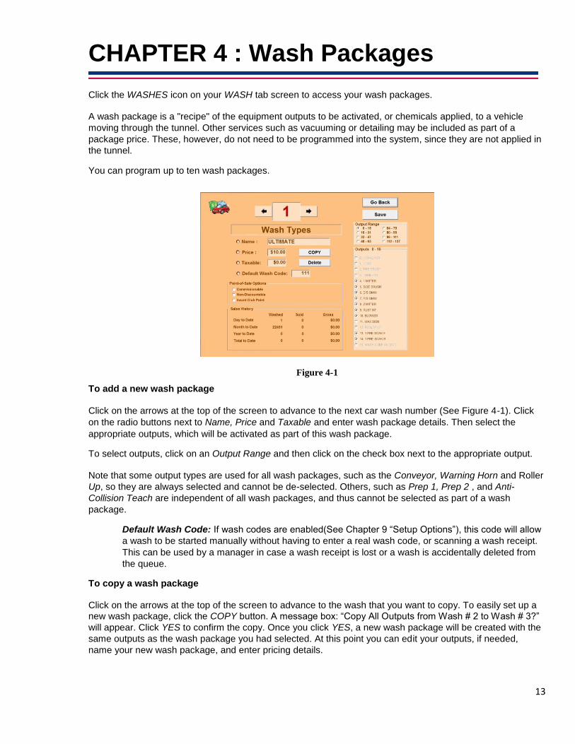
CHAPTER 4 : Wash Packages Click the WASHES icon on your WASH tab screen to access your wash packages. A wash package is a "recipe" of the equipment outputs to be activated, or chemicals applied, to a vehicle
moving through the tunnel. Other services such as vacuuming or detailing may be included as part of a
package price. These, however, do not need to be programmed into the system, since they are not applied in
the tunnel. You can program up to ten wash packages.
Figure 4-1 To add a new wash package Click on the arrows at the top of the screen to advance to the next car wash number (See Figure 4-1). Click
on the radio buttons next to Name, Price and Taxable and enter wash package details. Then select the
appropriate outputs, which will be activated as part of this wash package. To select outputs, click on an Output Range and then click on the check box next to the appropriate output. Note that some output types are used for all wash packages, such as the Conveyor, Warning Horn and Roller
Up, so they are always selected and cannot be de-selected. Others, such as Prep 1, Prep 2 , and Anti-
Collision Teach are independent of all wash packages, and thus cannot be selected as part of a wash
package.
Default Wash Code: If wash codes are enabled(See Chapter 9 “Setup Options”), this code will allow
a wash to be started manually without having to enter a real wash code, or scanning a wash receipt.
This can be used by a manager in case a wash receipt is lost or a wash is accidentally deleted from
the queue. To copy a wash package Click on the arrows at the top of the screen to advance to the wash that you want to copy. To easily set up a
new wash package, click the COPY button. A message box: “Copy All Outputs from Wash # 2 to Wash # 3?”
will appear. Click YES to confirm the copy. Once you click YES, a new wash package will be created with the
same outputs as the wash package you had selected. At this point you can edit your outputs, if needed,
name your new wash package, and enter pricing details.

14
To edit a wash package Scroll to the wash package you would like to edit (See Figure 4-1). Click on radio button next to line you
would like to edit. Don't forget to save changes when you exit the WASH tab screen. You can also check
or uncheck outputs included in the package
To delete a wash package Scroll to the wash package you would like to delete and click the Delete button (See Figure 4-1). You will
be prompted with "Do you really want to delete this entry?” Click YES to delete the wash package. The
sales data will be cleared and this number will be available for a new wash package. Remember: Save your changes frequently to ensure no data is lost in case of a communication
error! To save your changes, click the Save button located throughout the screens.
POS Options:
Commissionable – If you would like for a package to be considered commissionable, make sure to
check this option. If a wash is commissionable, choosing that wash at the POS will cause a list of clocked
in employees to appear. Whichever employee is chosen will be credited with that sale in the
commission’s report.
Non-Discountable – Choosing Non-Discountable means that the wash will not be discounted if it is put
on a ticket with a discount.
Award Club Point Eligibility – Checking this option for a wash will cause a customer to receive a loyalty
point whenever they get that wash. This will count towards a loyalty program that was requested by you.
Buy five and get the sixth free for example.

15
CHAPTER 5 : Add-Ons Add-Ons , or upsells, are a-la-carte services performed or products applied in the tunnel not included
in the car wash package, but instead applied at an additional cost.
Figure 5-1
Setting up Add-Ons
1. Go to the WASH tab screen and click Add-Ons. 2. Scroll using the arrows at top of the screen and select a number not currently in use (See Figure 5-1). 3. Enter a Name, a Price and a Taxable amount. 4. Assign which output, or outputs, to activate when this Add-On is selected. 5. As with wash packages, Add-Ons can be modified or deleted.
Note: Coupons can be configured as Add-Ons and will affect the price of the wash. To have an Add-
On act as a coupon, enter a negative Price and make sure no outputs are selected.
Remember: Save your changes frequently to ensure no data is lost in case of a communication
error! To save your changes, click the Save button located throughout the screens.

16

17
CHAPTER 6 : Override Options Overrides, when selected by the operator, will activate the Retract output type and/or suppress the activation
of other output types. Overrides are used when a vehicle requires a certain function, or functions, to be de-
activated at the time of the wash by the technician operating the car wash. For example, if the vehicle
entering the tunnel is a convertible, the operator may want to select an override option for the top brush to
prevent possible damage to the convertible roof.
Configuring Overrides 1. Go to the WASH tab screen and click Overrides. 2. Scroll using the arrows at top of the screen and select a number not currently in use. 3. Enter a Name for the new Override. 4. Assign which output or outputs to de-activate or retract when this Override is selected.
Additional Information By default, the first override is Pickup Truck. This override cannot be changed or removed, but options may
be configured by going to Outputs. Note that certain output types may not be overridden. These include: Conveyor, Roller up, Anti-Collision
Teach, Anti-Collision sign and Warning Horn. Output types that will be suppressed when overridden include: Full Car, Front Bumper only, Rear Bumper
only, Dryer / Blower, Tire Device and Entrance Sign. The Retract output type will be activated when included as part of an Override.
Figure 6-1
Remember: Save your changes frequently to ensure no data is lost in case of a communication
error! To save your changes, click the Save button located throughout the screens.

18

19
CHAPTER 7 : Miscellaneous Menu
Figure -7-1
Conveyor and Rollers See Chapter 9 “Setup Options”.
INPUTS See Chapter 2 “Car Wash Inputs”.
Setup Options See Chapter 9 “Setup Options”.
Wet Down Wet down configuration.
Figure 7-2

20
Wet down is typically used in the morning prior to beginning car wash operations, or whenever there
has been a significant period of time between washed to ensure that brushes, mitters, etc. are
sufficiently wet and ready for vehicles. If not sufficiently wet down, the dry brushes may cause vehicle
damage. The Wet down function will operate equipment only for the period of time specified, and is only
available when the tunnel is otherwise not in use. Wet Down Time: The time, in seconds, you want selected outputs to operate.
Restart Outputs Figure 7-3 When recovering from an emergency stop, you can configure the order in which outputs re-start. To add
items into the re-start list, select the output in the Outputs list (see Figure 7-2), click Add and then move
up or down, as needed. Items will re-start in order, at two-second intervals. After the last item in your
Restart list is started, the Conveyor and any other remaining outputs will start. This feature is intended to
minimize the power spike of equipment startup.
Entrance Screen HMI Allows remote access to the touch button station.
Emergency Restore This option will restore controller settings from a copy automatically stored on a local machine. This
option is password protected and should only be used in case of an emergency.

21
Address / Time / Version Click Update Tunnel Logic to synchronize the time on the controller with your computer time (See Figure 7-4) Note: This feature should be used only if the wash equipment is not in use. Figure 7-5

22

23
CHAPTER 8 : Tunnel Logic Reports
Figure 8-1
Current Sales Reports
Previous Shift Report: Total sales for previous shift. Current Shift Report: Total sales for current shift. Daily Sales Report: Total sales for current day.
Fault Log: Will display a listing of all controller faults.
Figure 8-2
Past Sales Reports
Month to Date Report: Total sales for current month. Year to Date Report: Total sales for current year.

24
Consolidated Daily and Monthly: Total sales for a selected range of dates. Click the name of the
report you would like to generate, a starting date and an ending date and then click OK.
Figure 8-3
Outputs Activity Report
Summary of output activity, including minutes the output has been on during the day.
Figure 8-4
Remember: Save your changes frequently to ensure no data is lost in case of a communication error!
To save your changes, click the Save button located throughout the screens.

25
CHAPTER 9 : Setup Options
Conveyor and Rollers
Figure 9-1
Conveyor Load Conveyor: This parameter tells the system whether the initial roller will engage behind the front
tires or behind the rear tires to push the car along the conveyor. The number of rear rollers may also
be specified.
Conveyor Setup Inches per Pulse: Number of inches the conveyor moves forward with each pulse. If this
value is not known, it can be calculated by the controller using the Calibrate Pulse Routine.
For more information on this routine, see Chapter 15 “Setup”.
START conveyor timeout: If START is pressed on the touch button station, but no vehicle
is present to go through the wash, the conveyor will timeout and stop after specified time.
STOP conveyor timeout: After all washes are complete, the conveyor should continue to
operate for the specified amount of time.
Run Conveyor if Vehicle in Queue: Will start conveyor automatically if there is a
customer in the queue.
Start of Conveyor to Entrance eye: The distance between the start of the conveyor and the entry
photo eye. This parameter is required if the entry eye is not functional and the system is set to
Auto Eye Mode.
Entrance Eye to End of Conveyor Inches: The distance from the entry photo eye to the end of the conveyor measured in inches.
Seconds: The travel time of a vehicle from the entry photo eye to the end of the conveyor
measured in seconds. This parameter will be used if the system is set to Auto Pulse Mode.

26
Auto Pulse Mode: The pulse switch signals the conveyor speed to the controller, which allows the
controller to track the distance the vehicle has traveled in the tunnel. If the pulse meter is not functional, set
Auto Pulse Mode to ON. In Auto Pulse Mode, the controller will use the Entrance EYE to END of Conveyor
Inches and Seconds parameters to approximate the conveyor speed and simulate a pulse. Note that the
conveyor speed can only be approximated, but the wash can continue to operate if the pulse meter is not
functional. For more information on Auto Pulse Mode, see Chapter 15 “Setup”.
Rollers Roller Spacing: Required parameter that specifies the distance between each roller on the conveyor. Roller Pattern: Configures the pattern for rollers to be sent for each vehicle. The first roller will
always be in the UP position. Additional rollers may be sent or skipped to ensure the vehicle will be pushed
completely through the tunnel. Roller Counter at Trap Door: Specifies roller location in relation to roller-up fork. Remember: Save your changes frequently to ensure no data is lost in case of a communication
error! To save your changes, click the Save button located throughout the screens.
Anti-Collision Vehicle Detector: Photo eye at the end of a the tunnel that is able to determine when a vehicle has
cleared the tunnel. Enable when eye is working properly.
Extra A/C Margin: Determines amount of space between vehicles for the anti-collision to be activated.
5 Ft (60 inches) by default.

27
Setup Options
Figure 9-2
HMI Password Allows the operator to enter Test Mode at the Touch Button Station to manually activate outputs for
testing and diagnostics. For more information see Section 13 of this manual.
Gate Setup Max Cars in Queue: The number of cars that can fit between the gates and the tunnel entrance.
Use Wash Codes
When wash codes are enabled, normal tires and loading settings will be ignored. The technician will
have to enter the wash code at the Touch Button Station or scan the wash code to be able to start a
wash. When wash codes are enabled, there will also be an Auto Load option available to start the
wash automatically when the barcode on the wash receipt is scanned = “Wash Code Scan”
Add Washes to Queue from HMI When this is enabled, the technician will be able to add washes to the queue from the touch screen HMI
Auto Load Auto Start – Activated By: For customer self-loading, enter whether only front tires, or front and rear
tires are required to pass over a tire treadle to initiate the wash. This feature requires the installation
of an Autoload Tire Treadle Input. Set this value to None if the wash is to be started by an operator.
Auto Load Delay: If Auto Load is set to on, the controller will count down from the specified seconds
in Auto Load Delay before starting the conveyor.

28
Entry Eye
Input Signal to Controller: Specifies whether the entry eye input will be considered ON or OFF
when vehicle is present.
Pre-Wash Vehicle Prep: If the entry eye is often blocked while preparing the vehicle for the wash,
select OFTEN Blocks Entry Eye to better control when certain outputs will be started.
Auto Eye Mode : When the entry photo eye is working and a car enters the tunnel, it will break the
beam, signaling that a vehicle is present. By measuring the amount of time the signal is
interrupted, the system will determine the length of the vehicle and adjust the car wash accordingly.
If the entry photo eye is not functional, set Auto Eye Mode to ON. In Auto Eye Mode, a standard
vehicle size (Ford Expedition) is assumed and the Roller Spacing and the Roller up to Entry Gate
parameters are used to determine when each output should be activated. These parameters can
only approximate vehicle size, location and equipment on and off times, but the wash can
continue to operate even if the entry eye is not functional. For more information on Auto Eye
Mode, see Chapter 15 “Setup”. Installation Type Offset (Preferred): Photo eye at beginning of tunnel is offset. This is to better determine a pickup
truck when it hits the gap between the truck and the bed.
In-Line: Straight photo eye line up.
Restart after E-Stop To re-start the equipment after an emergency stop, you must first pull out the E-stop button mounted
on the Tunnel Logic controller door, second, press the green start button on the controller and third,
press the RESTART button on the Touch Button Station screen. To avoid this last step, select Skip
Restart Confirmation here.

29
CHAPTER 10 : Touch Button Station The wash operator will use the Touch Button Station to control all aspects of the tunnel. From this control
panel, the operator can initiate a wash, add or delete customers from the wash queue and test, diagnose, or
stop any output. In an express wash setting, the operator can also raise or lower the entry gates.
Figure 11-1 Wash button
Displays your active customer list where you can see the washes that are currently in the queue.
From there you can initiate a wash and add or remove washes from the queue. Setup button
Access to the diagnostic menus to view input and output activity, as seen by the controller. From
these menus any output can be switched to "Off" or put in "Auto" mode for normal operations, where
the output is ready to be turned on or off by the controller as needed. Sales button
Displays current sales data for wash. Conveyor Speed / Cars per Hour
Current chain speed calculated using pulse. This figure is not necessarily the same as throughput in
any given tunnel. Chain speed could be viewed as any car wash’s maximum throughput potential.
Throughput cars per hour is only dictated by how fast you can load and prep cars on any given chain
speed. (Cars Per Hour = 3600 Seconds in an Hour / # Seconds for one roller to travel 20 feet) English button
Runs the Touch Button Station in English. Español button
Runs the Touch Button Station in Spanish. Français button
Runs the Touch Button Station in French. русский button
Runs the Touch Button Station in Russian. Quick Tip: If you select a foreign language by mistake, remember that the yellow buttons always GO BACK.

30

31
CHAPTER 11 : Customer Queue Customers can be entered into the customer queue in 3 ways: • From a point-of-sale terminal • Manually from the Touch Button Station • From an automated cashier Queuing Customers from the Point-of-Sale terminal When a customer is added to the wash queue from the greeter station, the customer number and the type of
wash will appear in the customer list. This will match the greeter's printed pre-receipt. If the customer is
entered from the Cashier's Station, the license plate number will be displayed (If the license plate was not
used, the type of wash purchased and the total price will be displayed). Adding customers to the queue using the Touch Button Station From the main Tunnel Logic menu, press WASH to access your wash queue.
Figure 12-1
Press ADD WASH to build a new wash and you will be taken to the build wash options screen.
Figure 12-2 Select the type of wash by pressing the WASH button under the appropriate wash package name. Press
ADDONS to be taken to a second screen, where you can select additional addons.

32
Figure 12-3 Select any Upsells by pressing ADD ON (See Figure 12-3). Select Overrides by pressing the OVERRIDES
button (Figure 12-2).
Figure 12-4
Notice that although you can only select one type of WASH, you can select as many Upsells or Overrides as
you like. PRINT RECEIPT button (Figure 12-2) - When the PRINT RECEIPT button is pressed, a receipt for the
current wash will print. This feature will print if an optional car wash receipt printer is connected to the
touch button station. See Chapter 19 “Car Wash Printers” for more information on supported printers. RAIN CHECK button - When the RAIN CHECK button is pressed, the current wash will be treated as a rain
check redemption. Totals for rain check redemptions will be displayed in the Car Wash Exception report. Once all your options are selected, press GO BACK to return to the ADD WASH screen, and then press OK
to add the wash to the queue. Adding customers to the queue from an Automated Cashier Automated cashiers can be wired directly to the controller to automatically add customers to the wash queue.
When installed in this manner, the queue can be managed with Tunnel Logic ‘s built-in gate control to
enforce the correct queuing order. When using automated cashiers, the type of wash purchased is displayed
in the customer list.
33
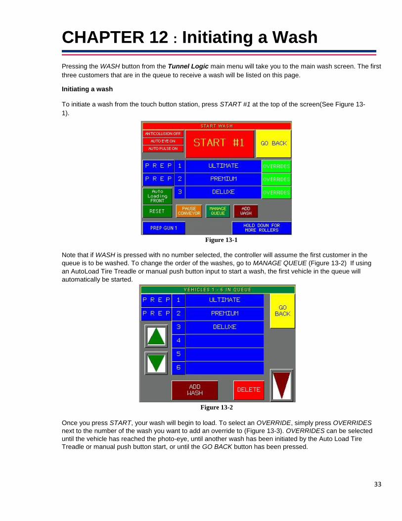
CHAPTER 12 : Initiating a Wash Pressing the WASH button from the Tunnel Logic main menu will take you to the main wash screen. The first
three customers that are in the queue to receive a wash will be listed on this page. Initiating a wash To initiate a wash from the touch button station, press START #1 at the top of the screen(See Figure 13-
1).
Figure 13-1
Note that if WASH is pressed with no number selected, the controller will assume the first customer in the
queue is to be washed. To change the order of the washes, go to MANAGE QUEUE (Figure 13-2) If using
an AutoLoad Tire Treadle or manual push button input to start a wash, the first vehicle in the queue will
automatically be started.
Figure 13-2
Once you press START, your wash will begin to load. To select an OVERRIDE, simply press OVERRIDES
next to the number of the wash you want to add an override to (Figure 13-3). OVERRIDES can be selected
until the vehicle has reached the photo-eye, until another wash has been initiated by the Auto Load Tire
Treadle or manual push button start, or until the GO BACK button has been pressed.

34
Figure 13-3 Press START when you are ready to initiate the wash. The START button will bypass the Auto Load
countdown and start the wash immediately. Once the wash has been started, the START button will change
to WASH IN PROGRESS.
Note: If the photo eye is blocked, the system will not allow a new wash to be initiated. Instead of the START
button, a warning message will display (See Figure 13-2). If the photo eye is broken, go to Auto Control
Settings and turn Auto Entrance Eye on. When the photo eye has been repaired, go back to Setup Options
and turn Auto Entrance Eye off, therefore resuming normal operating conditions. Figure 13-4
PREP GUNS - If the vehicle to be washed requires pre-prepping with prep guns, you can press the Prep
Gun 1 or Prep Gun 2 buttons. This will activate the selected prep gun immediately and you will see an "ON"
indicator. Prep guns will remain active for the time configured in the controller then automatically turn off. HOLD DOWN FOR MORE ROLLERS - Sends rollers until button is released. Will only work if the conveyor
is already running.
Deleting a wash from the queue From the main wash screen, press Manage Queue (Figure 13-2) to go to your full customer queue.
Select the wash you would like to delete by pressing the number to the left of the wash, then press DELETE.
From this screen, you can also change the order of the washes, by using the up and down arrow buttons.
Press GO BACK to return to the main wash screen.

35
CHAPTER 13 : Car Wash Sales Data To access your sales menus, press SALES from the main menu and then select DAILY or MONTHLY
SALES. Figure 14-1
Daily Sales Figure 14-2 START NEW SHIFT- Pressing this button will close out the current shift and begin a new one. Be sure
to print any report you would like to save before starting a new shift. PRINT SHIFT REPORT- Will print current shift data. Day to date values are automatically cleared out at
midnight and the shift is re-set to first shift. PRINT DAILY REPORT – Will print the current days report from an Ithica wash printer that is directly
connected to the HMI.
CONSOLIDATED DAILY SALES – Will allow you to select the day and month that you would like to print a daily sales report for. It also prints from the Ithica wash printer connected to the HMI
36
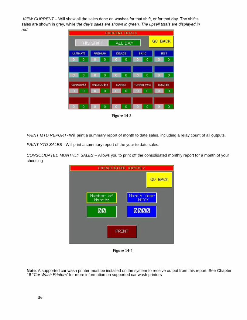
VIEW CURRENT – Will show all the sales done on washes for that shift, or for that day. The shift’s
sales are shown in grey, while the day’s sales are shown in green. The upsell totals are displayed in
red.
Figure 14-3
PRINT MTD REPORT- Will print a summary report of month to date sales, including a relay count of all outputs.
PRINT YTD SALES - Will print a summary report of the year to date sales.
CONSOLIDATED MONTHLY SALES – Allows you to print off the consolidated monthly report for a month of your
choosing
Figure 14-4 Note: A supported car wash printer must be installed on the system to receive output from this report. See Chapter 18 “Car Wash Printers” for more information on supported car wash printers

37
CHAPTER 14 : Setup To view setup, press the SETUP button from the Tunnel Logic main menu.
Figure 15-1
From SETUP you will be able to view inputs and outputs, and also access AUTO CONTROL SETTINGS and
GATES options.
Figure 15-2

38
Inputs & Outputs
Inputs Inputs 0-15 are pre-defined in the controller as shown in Figure 15-4. Inputs 28-31 are reserved for gate
control. All other inputs are configurable.
Figure 15-3 If an input is active, the number next to the input name will be displayed in red.
Outputs
Figure 15-4
The OUTPUTS screen displays a status of all outputs-- whether the output is set to ON, OFF, or AUTO
and whether the output is currently active. When an output is active, the ON button will be green. To
see more outputs use the up and down arrows. AUTO When an output is set to AUTO for normal operations, the output can be turned on or off by the
controller as needed. OFF If the output is set to OFF, the output will not activate. If the output is currently ON and OFF is pressed,
the output will stop. ON Pressing ON will force the output on and it will remain on until set back to AUTO or OFF.

39
Auto Control Settings
Figure 15-5
AUTO LOAD Will display current Auto Load setting. Turning Auto Load off will cause equipment to not start
automatically, but instead, only when wash is manually started.
AUTO ENTRY EYE When the entry photo eye is working and a car enters the tunnel, it will break the beam, signaling that a
vehicle is present. By measuring the amount of time the signal is interrupted, the system will determine the
length of the vehicle and adjust the car wash accordingly. If the entry photo eye is not functional, set Auto Entrance Eye to ON. In Auto Entrance Eye mode, a
standard vehicle size is assumed to determine when each output should be activated. Output activation
will not be as accurate, however the wash can continue to operate even if the entry photo eye is not
functional. Note that a password is not required to turn Auto Entrance Eye on or off. AUTO PULSE SWITCH If the pulse meter is not functional, the controller can approximate the conveyor speed and simulate a pulse by turning Auto Pulse Switch on. Note that since the conveyor speed is only approximated, output
activation may not be as accurate, however the wash can continue to operate. Note that a password is not required to turn Auto Pulse Switch on or off.
ANITICOLLISION This will tell you whether or not Anti-collision is enabled when there is a vehicle in the queue, flashing if it is enabled. When there is no vehicle in the queue, you will see NO VEHICLE next to it.

40
Gates In the GATES control screen, you can raise or lower the gates and calibrate the vehicle detection sensor
at each gate. The VEHICLE SENSOR indicator will turn on when a vehicle is present at each respective
sensor. This is useful for troubleshooting gates. Figure 15-6
Pinch Point Where the cashier lanes merge to a single lane. When a wash package is purchased at one of the automated cashiers, the gate will open to allow one
vehicle to pass through. Once a gate has opened, no other gates will be allowed to open until the first
gate has closed behind the vehicle and the vehicle has passed over the PINCH POINT vehicle detection
sensor. This ensures that vehicles enter the tunnel in the order they were queued in the controller. When using a Banner magnetometer as a vehicle detection sensor, the sensor must be calibrated to
measure the ambient magnetic field and establish a baseline reading. Thereafter, the sensor can detect a
vehicle by measuring variations in the magnetic field induced by a large metal object such as a vehicle.
Thesensor will need to be calibrated after installation and after any structural changes to the area that
may have affected the magnetic field.
To calibrate the PINCH POINT vehicle detection sensor, press CALIBRATE.
Anti-Collision This calibration should be performed when there are no cars in or near the tunnel. Running this calibration
will “teach” the ANTI-COLLISION sensor what normal conditions are without the presence of a vehicle.
After calibration, the sensor will be able to detect when the magnetic field around the sensor has changed,
therefore indicating the presence of a vehicle, and signal the conveyor to stop if necessary, to avoid a
collision.
Print Fault Log Will print a listing of all controller faults.
Wet Down Initiates equipment wet down.
41
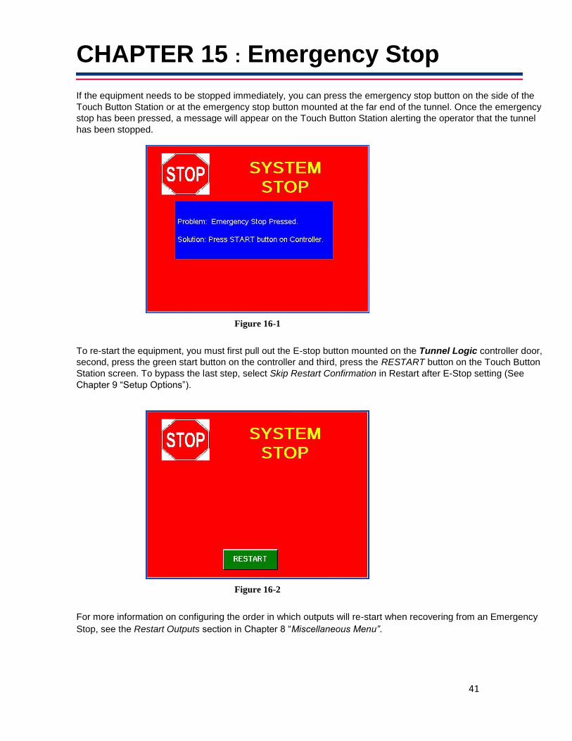
CHAPTER 15 : Emergency Stop If the equipment needs to be stopped immediately, you can press the emergency stop button on the side of the
Touch Button Station or at the emergency stop button mounted at the far end of the tunnel. Once the emergency
stop has been pressed, a message will appear on the Touch Button Station alerting the operator that the tunnel
has been stopped.
Figure 16-1
To re-start the equipment, you must first pull out the E-stop button mounted on the Tunnel Logic controller door,
second, press the green start button on the controller and third, press the RESTART button on the Touch Button
Station screen. To bypass the last step, select Skip Restart Confirmation in Restart after E-Stop setting (See
Chapter 9 “Setup Options”).
Figure 16-2
For more information on configuring the order in which outputs will re-start when recovering from an Emergency
Stop, see the Restart Outputs section in Chapter 8 “Miscellaneous Menu”.

42
43
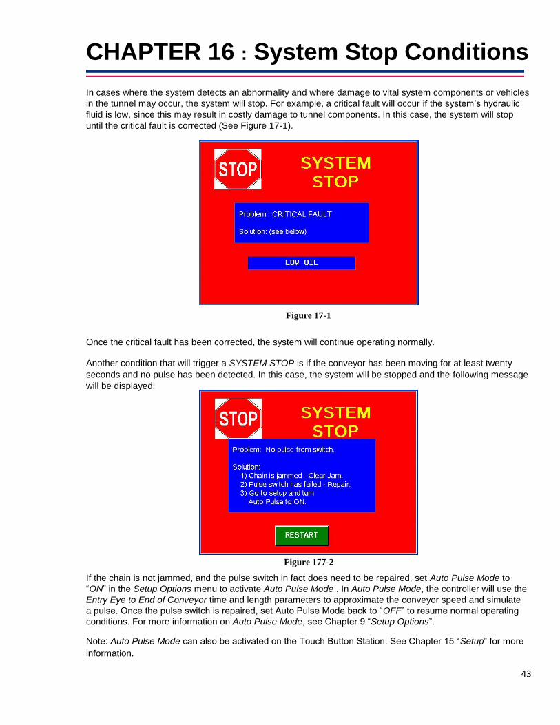
CHAPTER 16 : System Stop Conditions In cases where the system detects an abnormality and where damage to vital system components or vehicles
in the tunnel may occur, the system will stop. For example, a critical fault will occur if the system’s hydraulic
fluid is low, since this may result in costly damage to tunnel components. In this case, the system will stop
until the critical fault is corrected (See Figure 17-1).
Figure 17-1
Once the critical fault has been corrected, the system will continue operating normally. Another condition that will trigger a SYSTEM STOP is if the conveyor has been moving for at least twenty
seconds and no pulse has been detected. In this case, the system will be stopped and the following message
will be displayed:
Figure 177-2 If the chain is not jammed, and the pulse switch in fact does need to be repaired, set Auto Pulse Mode to
“ON” in the Setup Options menu to activate Auto Pulse Mode . In Auto Pulse Mode, the controller will use the
Entry Eye to End of Conveyor time and length parameters to approximate the conveyor speed and simulate
a pulse. Once the pulse switch is repaired, set Auto Pulse Mode back to “OFF” to resume normal operating
conditions. For more information on Auto Pulse Mode, see Chapter 9 “Setup Options”. Note: Auto Pulse Mode can also be activated on the Touch Button Station. See Chapter 15 “Setup” for more
information.

44

45
CHAPTER 17 : Car Wash Printers Auto Data recommends the Ithaca iTherm 900, but will configure any serial car wash printer that fits the
following specifications: (Baud Rate: 19200 BPS, Mode: 8 Bit Even Parity 1 Stop Bit). The printer will need to
be sent in to Auto Data to be configured. As a courtesy, Auto Data can also add your company logo to your
car wash receipts.

46

47
CHAPTER 18 : Configuring HTK
Communications between the HTK and the controller.
1. From the Main Menu go to Configuration.
Figure 19-1
2. Press Application. 3. Press Next Page two times to get to the Vend option.
Figure 19-2

48
4. Press Vend.
Figure 19-3
5. Select Ethernet.
Figure 19-4

49
6. Apply the following settings for HTK 1, 2 and 3. When you are done, press Activate Changes, and then
Back to exit.
Figure 19-5 – HTK Lane 1 Settings
Figure 19-6 – HTK Lane 2 Settings

50
Figure 19-7 – HTK Lane 3 Settings

51
How to Access ‘Service Mode’ on HTKs
1.) Use the key at the top of the HTK to access the servicing portion
of the HTK screen by turning the key 90 degrees and wait until
screen flickers and shows the screen about entering a User Code
and Password.
2.) At the HTK, login using the Administrator account:
User Code – 00
Password – 12345
(These are the default passwords to access the HTK Servicing
Mode.)
3.) Once at the Hamilton Service Mode screen, select the option
“Service Mode” at the upper right corner.
4.) Then select “Service Mode Reboot”.
5.) It will bring up a screen asking for a User name and Password
that will look familiar to a Windows login screen. Enter these
credentials.
Hamilton Administrator Password : 51You92Up
6.) The system will reboot and bring you to Windows User Account
screen and will prompt you for the same credentials of Hamilton
Administrator so enter the password: 51You92Up.
7.) After entering the credentials you will be at a Windows desktop
screen and you will begin by setting the correct date and time.
8.) Finish by setting the Network Configurations as instructed
below. There is list of instructions of how to exit the ‘Service
Mode’ once completed with configuring the Network settings.

52
HTK Network Settings
1. Right-Click Windows Symbol on bottom left hand corner of screen and select the option Control Panel
Figure 19-8 2. From the options under the Control Panel menu, select Network and
Sharing Center.
Figure 19-9
53
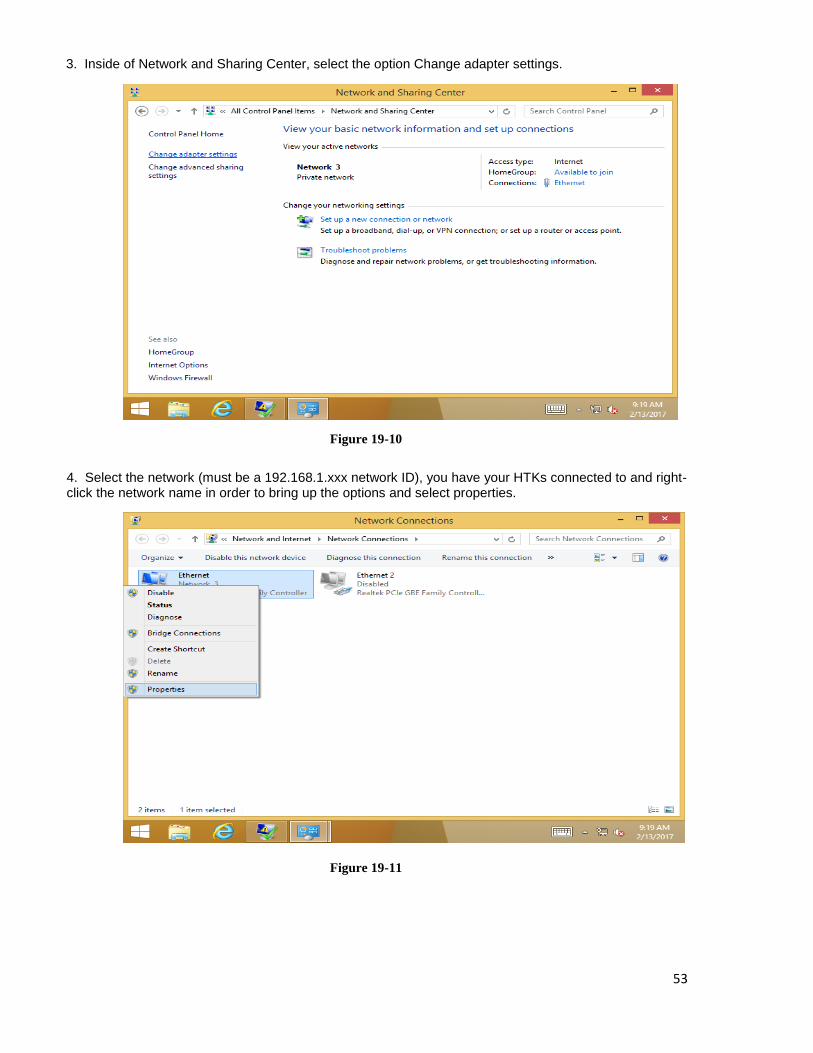
3. Inside of Network and Sharing Center, select the option Change adapter settings.
Figure 19-10
4. Select the network (must be a 192.168.1.xxx network ID), you have your HTKs connected to and right-click the network name in order to bring up the options and select properties.
Figure 19-11
54
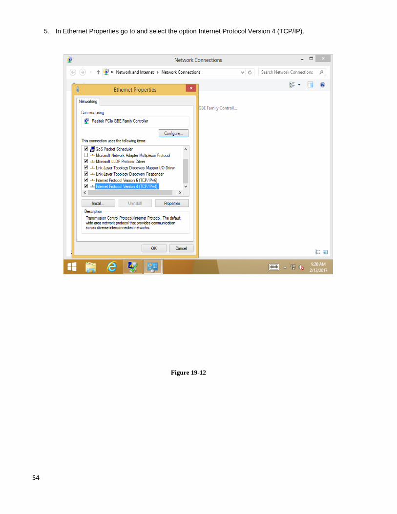
5. In Ethernet Properties go to and select the option Internet Protocol Version 4 (TCP/IP).
Figure 19-12

55
6. Apply the following settings for HTKs 1, 2 and 3:
Figure 19-13 – HTK Lane 1 Settings

56
Figure 19-14 – HTK Lane 2 Settings
Figure 19-15 – HTK Lane 3 Settings

57
7. After applying Network change settings press OK as prompted until you are back at Network Sharing Center. Then go back to the desktop and select Exit Service Mode. After selecting Exit Service Mode it will bring up a command prompt box and it will ask to type Y/N. Type Y and press enter. It will now take you back to the HTK OS.
8. After applying the Network Settings you will now be able to set up users to gain access remotely to apply all other HTK configurations.
58
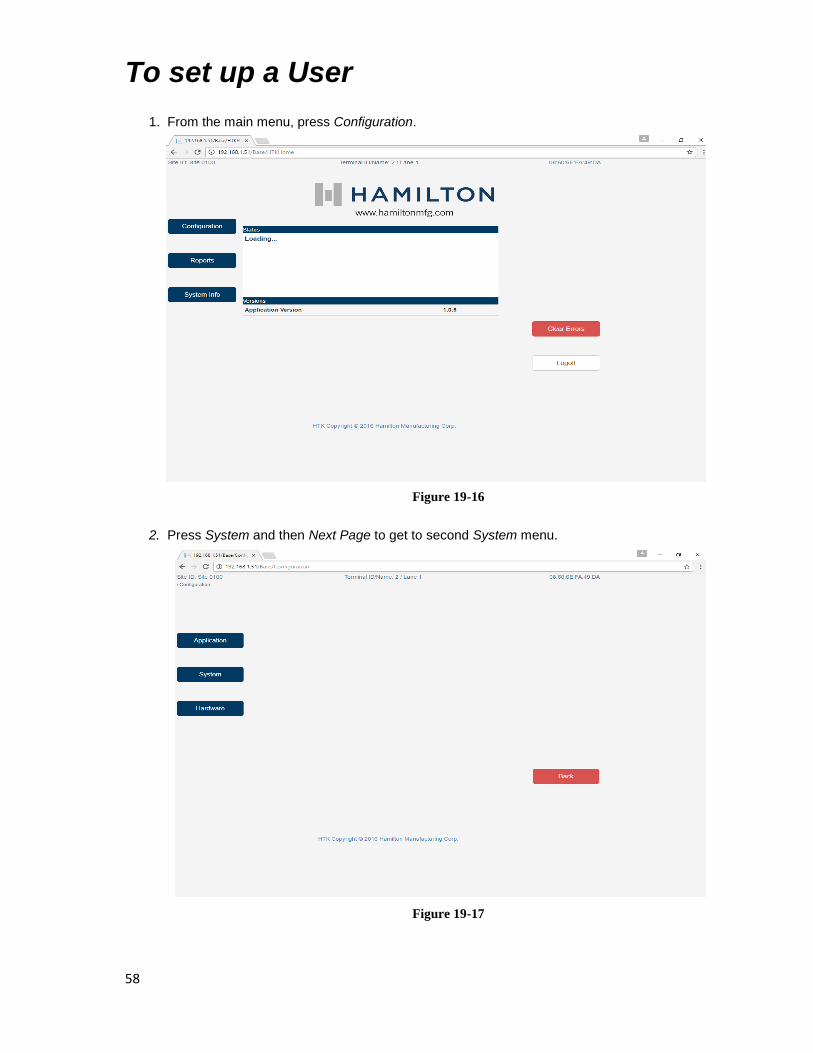
To set up a User
1. From the main menu, press Configuration.
Figure 19-16
2. Press System and then Next Page to get to second System menu.
Figure 19-17

59
3. Press Users.
Figure 19-18 4. Press the Add button. 5. Check Enable User. 6. Enter “Auto Data” in the Full Name field. 7. Enter “2121” in the User Code field. 8. Enter “54321” in the Local Password field. 9. Enter “AutoData1” in the Remote Password field 10. Enter “[email protected]” in the Email field. 11. Click the Rights tab and check all the Rights’ boxes.
Figure 19-19
12. Press Activate Changes and then Back to exit. Once you set up a user you can access the HTK remotely by typing the IP address you entered in on each HTK in a web address bar. Use the credentials for the remote user on the web page.
60
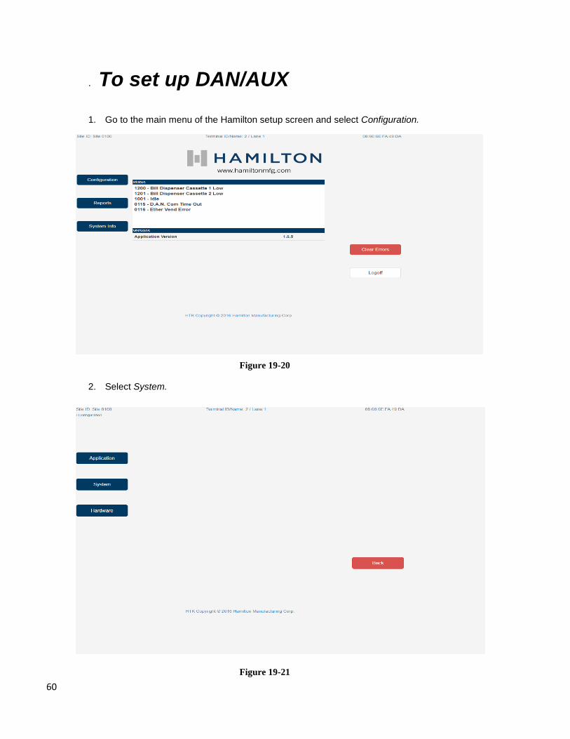
. To set up DAN/AUX 1. Go to the main menu of the Hamilton setup screen and select Configuration.
Figure 19-20
2. Select System.
Figure 19-21

61
3. Select Network.
Figure 19-22
4. Select DAN/AUX.
Figure 19-23
62
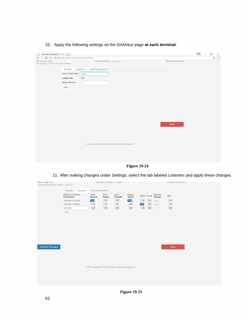
10. Apply the following settings on the DAN/Aux page at each terminal:
Figure 19-24
11. After making changes under Settings, select the tab labeled Listeners and apply these changes.
Figure 19-25

63
12. Press Activate Changes. Press Back to return to the main Network menu. 13. Press Back again to return to the main System menu.
Figure 19-26

64

65
Queue Settings
1. From the main menu, press Configuration.
Figure 19-27
2. Press Application.
Figure 19-28

66
3. Press Next Page one time and then select Queue.
Figure 19-29
4. Make sure Cycle Signal Operation is set to “Not Required”. This setting signals to the HTK that it
does not need to control the queue. In this case Auto Data’s controller will do this and the HTK will
always accept washes.
Figure 19-30

67
Configuring Terminal ID Settings
1. From the main menu, press Configuration.
Figure 19-31
2. Click System.
Figure 19-32
68
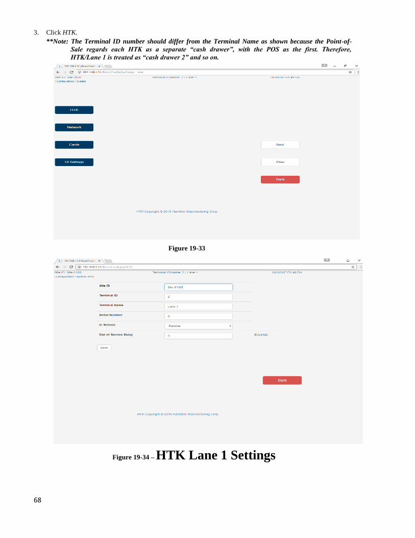
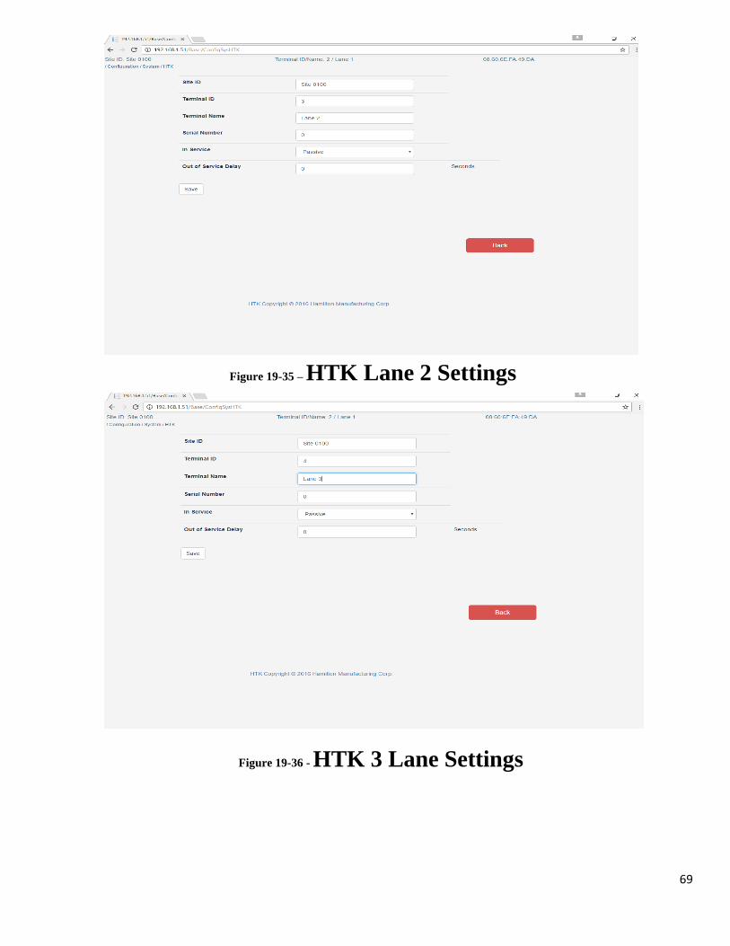
3. Click HTK. **Note: The Terminal ID number should differ from the Terminal Name as shown because the Point-of-
Sale regards each HTK as a separate “cash drawer”, with the POS as the first. Therefore,
HTK/Lane 1 is treated as “cash drawer 2” and so on.
Figure 19-33
Figure 19-34 – HTK Lane 1 Settings
69
Figure 19-35 – HTK Lane 2 Settings
Figure 19-36 - HTK 3 Lane Settings

70
To enable Barcode 1. To enable printing a barcode on the wash code receipt, from the main menu, press Configuration.
Figure 19-37
2. Press Application.
Figure 19-38

71
3. Press Next Page two times to get to the third Application menu.
Figure 19-39 4. Press Barcode. 5. Enter following settings:
Figure 19-40 6. Click Save.

72

73
Appendix A ----------------------------------------------------------------------------------- Outputs Worksheet


75
OUTPUTS WORKSHEET
6/17/2008 Store # 0001 Page 1 OUTPUT =============== BLOCK #1 - BANK #1 ===================
# Wire Description Type Eye On Off Ahead --- ---- -------------------- ------------------- ---- ---- ---- ----- 0 100 ____________________ ___________________ ____ ____ ____ _____
1 101 ____________________ ___________________ ____ ____ ____ _____
2 102 ____________________ ___________________ ____ ____ ____ _____
3 103 ____________________ ___________________ ____ ____ ____ _____
OUTPUT =============== BLOCK #1 - BANK #2 ===================
# Wire Description Type Eye On Off Ahead --- ---- -------------------- ------------------- ---- ---- ---- ----- 4 104 ____________________ ___________________ ____ ____ ____ _____
5 105 ____________________ ___________________ ____ ____ ____ _____
6 106 ____________________ ___________________ ____ ____ ____ _____
7 107 ____________________ ___________________ ____ ____ ____ _____
OUTPUT =============== BLOCK #1 - BANK #3 ===================
# Wire Description Type Eye On Off Ahead --- ---- -------------------- ------------------- ---- ---- ---- ----- 8 108 ____________________ ___________________ ____ ____ ____ _____
9 109 ____________________ ___________________ ____ ____ ____ _____
10 110 ____________________ ___________________ ____ ____ ____ _____
11 111 ____________________ ___________________ ____ ____ ____ _____
OUTPUT =============== BLOCK #1 - BANK #4 ===================
# Wire Description Type Eye On Off Ahead --- ---- -------------------- ------------------- ---- ---- ---- ----- 12 112 ____________________ ___________________ ____ ____ ____ _____
13 113 ____________________ ___________________ ____ ____ ____ _____
14 114 ____________________ ___________________ ____ ____ ____ _____
15 115 ____________________ ___________________ ____ ____ ____ _____
- - - Continued on Next Page - - -

76
OUTPUTS WORKSHEET
6/17/2008 Store # 0001 Page 2 OUTPUT =============== BLOCK #2 - BANK #1 ===================
# Wire Description Type Eye On Off Ahead --- ---- -------------------- ------------------- ---- ---- ---- ----- 16 100 ____________________ ___________________ ____ ____ ____ _____
17 101 ____________________ ___________________ ____ ____ ____ _____
18 102 ____________________ ___________________ ____ ____ ____ _____
19 103 ____________________ ___________________ ____ ____ ____ _____
OUTPUT =============== BLOCK #2 - BANK #2 ===================
# Wire Description Type Eye On Off Ahead --- ---- -------------------- ------------------- ---- ---- ---- ----- 20 104 ____________________ ___________________ ____ ____ ____ _____
21 105 ____________________ ___________________ ____ ____ ____ _____
22 106 ____________________ ___________________ ____ ____ ____ _____
23 107 ____________________ ___________________ ____ ____ ____ _____
OUTPUT =============== BLOCK #2 - BANK #3 ===================
# Wire Description Type Eye On Off Ahead --- ---- -------------------- ------------------- ---- ---- ---- ----- 24 108 ____________________ ___________________ ____ ____ ____ _____
25 109 ____________________ ___________________ ____ ____ ____ _____
26 110 ____________________ ___________________ ____ ____ ____ _____
27 111 ____________________ ___________________ ____ ____ ____ _____
OUTPUT =============== BLOCK #2 - BANK #4 ===================
# Wire Description Type Eye On Off Ahead --- ---- -------------------- ------------------- ---- ---- ---- ----- 28 112 ____________________ ___________________ ____ ____ ____ _____
29 113 ____________________ ___________________ ____ ____ ____ _____
30 114 ____________________ ___________________ ____ ____ ____ _____
31 115 ____________________ ___________________ ____ ____ ____ _____
- - - Continued on Next Page - - -

77
OUTPUTS WORKSHEET
6/17/2008 Store # 0001 Page 3 OUTPUT =============== BLOCK #3 - BANK #1 ===================
# Wire Description Type Eye On Off Ahead --- ---- -------------------- ------------------- ---- ---- ---- ----- 32 100 ____________________ ___________________ ____ ____ ____ _____
33 101 ____________________ ___________________ ____ ____ ____ _____
34 102 ____________________ ___________________ ____ ____ ____ _____
35 103 ____________________ ___________________ ____ ____ ____ _____
OUTPUT =============== BLOCK #3 - BANK #2 ===================
# Wire Description Type Eye On Off Ahead --- ---- -------------------- ------------------- ---- ---- ---- ----- 36 104 ____________________ ___________________ ____ ____ ____ _____
37 105 ____________________ ___________________ ____ ____ ____ _____
38 106 ____________________ ___________________ ____ ____ ____ _____
39 107 ____________________ ___________________ ____ ____ ____ _____
OUTPUT =============== BLOCK #3 - BANK #3 ===================
# Wire Description Type Eye On Off Ahead --- ---- -------------------- ------------------- ---- ---- ---- ----- 40 108 ____________________ ___________________ ____ ____ ____ _____
41 109 ____________________ ___________________ ____ ____ ____ _____
42 110 ____________________ ___________________ ____ ____ ____ _____
43 111 ____________________ ___________________ ____ ____ ____ _____
OUTPUT =============== BLOCK #3 - BANK #4 ===================
# Wire Description Type Eye On Off Ahead --- ---- -------------------- ------------------- ---- ---- ---- ----- 44 112 ____________________ ___________________ ____ ____ ____ _____
45 113 ____________________ ___________________ ____ ____ ____ _____
46 114 ____________________ ___________________ ____ ____ ____ _____
47 115 ____________________ ___________________ ____ ____ ____ _____
- - - Continued on Next Page - - -

78
OUTPUTS WORKSHEET
6/17/2008 Store # 0001 Page 4 OUTPUT =============== BLOCK #4 - BANK #1 ===================
# Wire Description Type Eye On Off Ahead --- ---- -------------------- ------------------- ---- ---- ---- ----- 48 100 ____________________ ___________________ ____ ____ ____ _____
49 101 ____________________ ___________________ ____ ____ ____ _____
50 102 ____________________ ___________________ ____ ____ ____ _____
51 103 ____________________ ___________________ ____ ____ ____ _____
OUTPUT =============== BLOCK #4 - BANK #2 ===================
# Wire Description Type Eye On Off Ahead --- ---- -------------------- ------------------- ---- ---- ---- ----- 52 104 ____________________ ___________________ ____ ____ ____ _____
53 105 ____________________ ___________________ ____ ____ ____ _____
54 106 ____________________ ___________________ ____ ____ ____ _____
55 107 ____________________ ___________________ ____ ____ ____ _____
OUTPUT =============== BLOCK #4 - BANK #3 ===================
# Wire Description Type Eye On Off Ahead --- ---- -------------------- ------------------- ---- ---- ---- ----- 56 108 ____________________ ___________________ ____ ____ ____ _____
57 109 ____________________ ___________________ ____ ____ ____ _____
58 110 ____________________ ___________________ ____ ____ ____ _____
59 111 ____________________ ___________________ ____ ____ ____ _____
OUTPUT =============== BLOCK #4 - BANK #4 ===================
# Wire Description Type Eye On Off Ahead --- ---- -------------------- ------------------- ---- ---- ---- ----- 60 112 ____________________ ___________________ ____ ____ ____ _____
61 113 ____________________ ___________________ ____ ____ ____ _____
62 114 ____________________ ___________________ ____ ____ ____ _____
63 115 ____________________ ___________________ ____ ____ ____ _____

79

![Cover RX-60 5030[J]f - JVC USA - Productsresources.jvc.com/Resources/00/00/97/22026ien.pdf · digital auto spk one touch operation bass boost pro logic dsp h. phone auto muting tuned](https://static.fdocuments.in/doc/165x107/5aff4a9f7f8b9a994d903332/cover-rx-60-5030jf-jvc-usa-auto-spk-one-touch-operation-bass-boost-pro-logic.jpg)