Tuning Your Design with new Simulink Control Tools · PDF file2 ® ® Presentation...
12
© 2007 The MathWorks, Inc. ® ® Tuning Your Design with new Simulink Control Tools Rohit Shenoy Simulink ® Control Tools Marketing 6th June 2007
Transcript of Tuning Your Design with new Simulink Control Tools · PDF file2 ® ® Presentation...
©20
07 T
he M
athW
orks
, Inc
.
® ®
Tuning Your Design with new Simulink Control ToolsRohit ShenoySimulink® Control Tools Marketing
6th June 2007

2
® ®
Presentation Overview
Multi-loop control designOverview of multi-loop compensator design in Simulink®
Guidance control system design using a Simulink model of an HL-20 lifting body
3
® ®
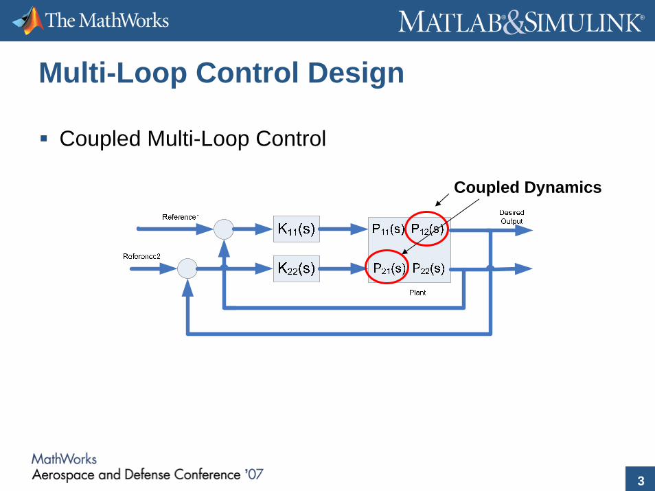
Multi-Loop Control Design
Coupled Multi-Loop Control
Coupled Dynamics

4
® ®
Challenges of Control DesignFeedback structure may be fixed and controllers are distributedMulti-Loop Design has inherent loop interaction effectsMany controllers are fixed structure, ex:
Feedback Control Elements
Controllers
( )1
1
ττ+
=s
sG
5
® ®
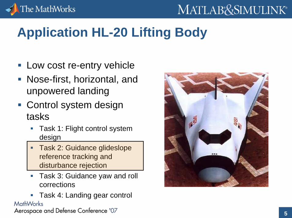
Application HL-20 Lifting Body
Low cost re-entry vehicleNose-first, horizontal, and unpowered landingControl system design tasks
Task 1: Flight control system designTask 2: Guidance glideslopereference tracking and disturbance rejectionTask 3: Guidance yaw and roll correctionsTask 4: Landing gear control

6
® ®
HL-20 – Glideslope Control Problem
h
dDesired Height
Actual Height
To Angle of AttackCommand
Feedback Controller
Goal: Build a feedback controller to controlthe height of the aircraft given the distance to the runway

7
® ®
Cross Wind
Lateral Glideslope Regulation
Flight path must remain within the coneNeed to devise controller to reject the cross wind disturbanceNearing landing need to recover any roll angle for a clean landing
Landing Cone to hitrunway
Use Roll to Bank Aircraft
Automaticroll recoveryat landing

8
® ®
Side Gust Control
Build a bump-less transfer controller (A) to switch between
(B) Controlling the drift of the aircraft due to cross wind(C) Recovering the roll angle at landing
B
C
A1
Out1Xe Phi Desired
y Control
y Control State
Euler
Phi Control Enable
Phi Desired
Phi Recovery Control
Xe
y Control
Phi Control
Phi desired
Switch Signal
Controller Switching Logic
1In1
<Xe>
<Euler>
9
® ®
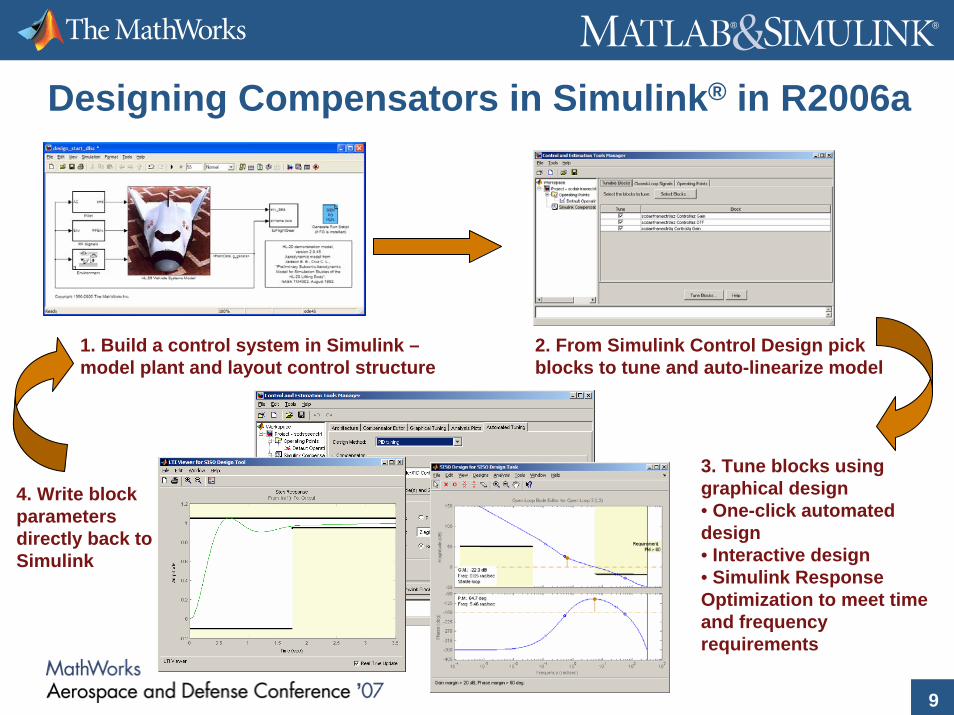
Designing Compensators in Simulink® in R2006a
1. Build a control system in Simulink –model plant and layout control structure
2. From Simulink Control Design pick blocks to tune and auto-linearize model
3. Tune blocks using graphical design• One-click automated design• Interactive design• Simulink Response Optimization to meet time and frequency requirements
4. Write block parameters directly back to Simulink

10
® ®
Design Goals
Robustness Requirement:AoA Loop maintain a phase margin > 35 degrees
Height reference trackingStep Response
Time (sec)
Ampl
itude
0 2 4 6 8 10 12-1
-0.5
0
0.5
1
1.5
2
h
d
11
® ®
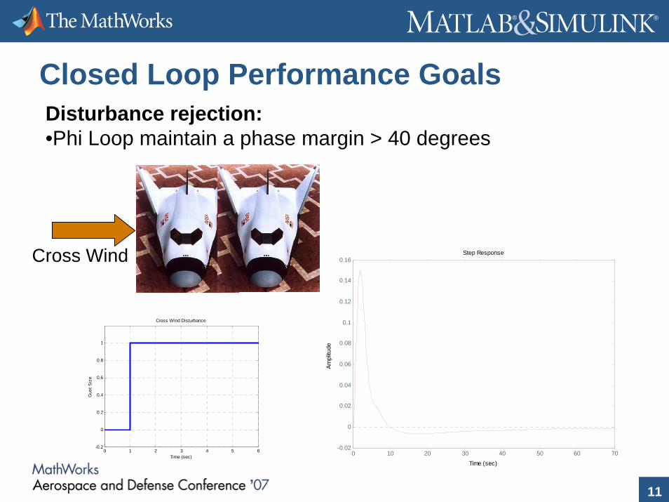
Closed Loop Performance GoalsDisturbance rejection:•Phi Loop maintain a phase margin > 40 degrees
Step Response
Time (sec)
Ampl
itude
0 10 20 30 40 50 60 70-0.02
0
0.02
0.04
0.06
0.08
0.1
0.12
0.14
0.16Cross Wind
0 1 2 3 4 5 6-0.2
0
0.2
0.4
0.6
0.8
1
Time (sec)
Gus
t Siz
e
Cross Wind Disturbance

12
® ®
Conclusions
New integrated workflow interface centered around SimulinkBuild any control structure in Simulink and tune the compensators using these toolsTune multi-loop control systems in a single design environmentUse graphical numerical optimization for compensator tuning, including frequency domain requirements
For more: Exhibit – Control System Design in Simulink