Tungaloy Report No. 530-US High precision and productivity ...
20
DrillLine High precision and productivity solution for finishing hole operations Tungaloy Report No. 530-US www.tungaloy.com/us
Transcript of Tungaloy Report No. 530-US High precision and productivity ...

DrillLine
High precision and productivity solution for finishing hole operations
Tungaloy Report No. 530-US
w w w . t u n g a l o y . c o m / u s
A C C E L E R A T E D M A C H I N I N G

DrillLine
w w w . t u n g a l o y . c o m / u s
New generation reamer for fi nishing hole operations

REAMMEISTER4
H7
H7 H7
0.45280 0.70866 +18 / 0 +15 / +11
0.70870 1.18110 +21 / 0 +17 / +13
1.18114 1.25984 +25 / 0 +21 / +16
660
495
330
165
0 0.002 0.004 0.006 0.008
DC
Innovative head clamping system ensures high quality and productive reaming operations
High precision reamer heads for applications of H7 hole tolerance range
Allows applications of higher cutting speeds and feed rates over solid carbide or brazed reamers, ensuring high productivityApplicable machining area
Max.hole size
Head DiameterDC
Min.hole size
Nominal hole diameter (inch) Hole diameter tolerance (μm) ReamMeister head tolerance DC (μm)
Above Up to & including
Cut
ting
spee
dVc
(sfm
)
Feed per tooth fz (ipt)
Solid carbideand
brazed reamers
• Head diameters are produced so that the hole diameter achieved is close to the max tolerance limit.

5w w w . t u n g a l o y . c o m / u s
A CC E L E R A T E D M A C H I N I N G
Innovative head clamping system ensures a runout accuracy and repeatability
2 types of reamer heads are available depending on the hole typesDiameters: ø0.45276" - ø1.25984"
AS Type
Straight flute
For blind holes
BL Type
Left hand flute
For through holes
- Dedicated screw pulls the head towards the shank when tightened, clamping the reamer head securely in place, allowing easy head indexing with no need for clamping screws as in the case with indexable reamers
- Face and taper contact provides secure clamping of the head to ensure high repeatability with minimal runout
- Internal coolant bores are arranged in radial directions on the reamer head so the cutting edges are effectively cooled and lubricated during machining, ensuring long tool life
* Can be used also for e xternal coolant supply
Clamping mechanism Coolant supply
Key
Reamer head
Dedicated screw
Holder
Parts
Chip evacuation in rear
Chip evacuation in front
*Can be used for through holes

REAMMEISTER6
0.70937
0.70929
0.70921
0.70913
0.70906
0.70898
0.70890
0.70882
0.70874
0.70866
0.03937
0.03543
0.03150
0.02756
0.02362
0.01969
0.01575
0.01181
0.00787
0.00394
Vc = 328 (sfm), 3D
Vc = 492 (sfm), 3D
Vc = 656 (sfm), 3D
Vc = 328 (sfm), 5D
Vc = 492 (sfm), 5D
Vc = 656 (sfm), 5D
Vc = 328 (sfm), 3D
Vc = 492 (sfm), 3D
Vc = 656 (sfm), 3D
Vc = 328 (sfm), 5D
Vc = 492 (sfm), 5D
Vc = 656 (sfm), 5D
Vc = 328 (sfm), 3D
Vc = 492 (sfm), 3D
Vc = 656 (sfm), 3D
Vc = 328 (sfm), 5D
Vc = 492 (sfm), 5D
Vc = 656 (sfm), 5D
Vc = 328 (sfm), 3D
Vc = 492 (sfm), 3D
Vc = 656 (sfm), 3D
Vc = 328 (sfm), 5D
Vc = 492 (sfm), 5D
Vc = 656 (sfm), 5D
0 0.002 0.004 0.006 0.008
0.70937
0.70929
0.70921
0.70913
0.70906
0.70898
0.70890
0.70882
0.70874
0.70866
0.03937
0.03543
0.03150
0.02756
0.02362
0.01969
0.01575
0.01181
0.00787
0.00394
0 0.002 0.004 0.006 0.008 0 0.002 0.004 0.006 0.008
0 0.002 0.004 0.006 0.008
Hole diameters machined with ReamMeister have exhibited minimum deviations at all cutting conditions, providing consistency in hole accuracy
Hole diameter accuracy Surface finish
H7 toleranceH7 tolerance
H7 toleranceH7 tolerance
Tool
Head
Workpiece material
Hole type
Pre hole diameter
Hole depth
Coolant
Ho
le d
iam
ete
r (inch)
Feed per tooth
fz (ipt)
Feed per tooth
fz (ipt)
Feed per tooth
fz (ipt)
Feed per tooth
fz (ipt)
Su
rface f
inis
h R
a (in
ch
)
Tool
Head
Workpiece material
Hole type
Pre hole diameter
Hole depth
Coolant
Hole diameter accuracy Surface finish
Ho
le d
iam
ete
r (inch)
Su
rface f
inis
h R
a (in
ch
)
CUTTING PERFORMANCE
: TRM-T7-R20-3, TRM-T7-R20-5
: HRM-0.7087-AS-T7 AH725
: 1055
: Blind
: ø0.7008"
: H = 1.18" (L/D = 1.7)
: Internal
: TRM-T7-R20-3, TRM-T7-R20-5
: HRM-0.7087-AS-T7 AH725
: 1055
: Through
: ø0.7008"
: H = 1.18" (L/D = 1.7)
: Internal

7w w w . t u n g a l o y . c o m / u s
A CC E L E R A T E D M A C H I N I N G
0.47315
0.47307
0.47299
0.47291
0.47283
0.47276
0.47268
0.47260
0.47252
0.472440 25 50 75 100
0.47315
0.47307
0.47299
0.47291
0.47283
0.47276
0.47268
0.47260
0.47252
0.472440 65 130 195 260
TOOL LIFE
Tool
Head
Cutting speed
Feed per tooth
Tool
Cutting speed
Feed per tooth
Solid Reamer
Workpiece material
Hole type
Pre hole diameter
Hole depth
Coolant
The tool life of ReamMeister is tripled even in high speed machining
Hole diameter reduction was small with ReamMeister even after machining 260 feet
Workpiece material
Hole type
Pre hole diameter
Hole depth
Coolant
Tool
Head
Cutting speed
Feed per tooth
H7 toleranceH7 tolerance
H7 toleranceH7 tolerance
Ho
le d
iam
ete
r (inch)
Total distance machined (ft)
Solid Reamer
Ho
le d
iam
ete
r (inch)
Total distance machined (ft)
Still available
: 1055
: Blind
: ø0.4646"
: H = 1.18" (L/D = 2.5)
: Internal
: 80-55-06
: Blind
: ø0.4646"
: H = 1.18" (L/D = 2.5)
: Internal
: ø0.4725" Solid Reamer (Uncoated)
: Vc = 164 sfm
: fz = 0.004 ipt
: TRM-T5-R16-3
: HRM-0.4725-AS-T5 AH725
: Vc = 492 sfm
: fz = 0.004 ipt
: TRM-T5-R16-3
: HRM-0.4725-AS-T5 AH725
: Vc = 492 sfm
: fz = 0.004 ipt
REAMMEISTER8
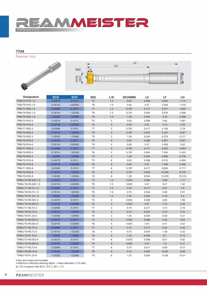
TRM
DCN DCX SSC L/D DCONMS L5 LF LH
TRM-T5-R16-1.5 0.45276 0.5315 T5 1.5 0.63 0.366 3.063 1.173
TRM-T6-R16-1.5 0.53154 0.62993 T6 1.5 0.63 0.37 3.209 1.319
TRM-T7-R20-1.5 0.62996 0.7874 T7 1.5 0.787 0.417 3.571 1.602
TRM-T8-R20-1.5 0.78744 1.02358 T8 1.5 0.787 0.504 3.976 2.008
TRM-T9-R32-1.5 1.02362 1.25984 T9 1.5 1.26 0.504 4.76 2.398
TRM-T5-R16-3 0.45276 0.5315 T5 3 0.63 0.366 3.85 1.961
TRM-T6-R16-3 0.53154 0.62993 T6 3 0.63 0.37 4.15 2.26
TRM-T7-R20-3 0.62996 0.7874 T7 3 0.787 0.417 4.748 2.78
TRM-T8-R20-3 0.78744 1.02358 T8 3 0.787 0.504 5.425 3.457
TRM-T9-R32-3 1.02362 1.25984 T9 3 1.26 0.504 6.579 4.217
TRM-T5-R16-5 0.45276 0.5315 T5 5 0.63 0.366 4.921 3.031
TRM-T6-R16-5 0.53154 0.62993 T6 5 0.63 0.37 5.409 3.52
TRM-T7-R20-5 0.62996 0.7874 T7 5 0.787 0.417 6.323 4.354
TRM-T8-R20-5 0.78744 1.02358 T8 5 0.787 0.504 7.394 5.425
TRM-T9-R32-5 1.02362 1.25984 T9 5 1.26 0.504 9.098 6.736
TRM-T5-R16-8 0.45276 0.5315 T5 8 0.63 0.366 6.516 4.626
TRM-T6-R16-8 0.53154 0.62993 T6 8 0.63 0.37 7.299 5.409
TRM-T7-R20-8 0.62996 0.7874 T7 8 0.787 0.417 8.685 6.717
TRM-T8-R20-8 0.78744 1.02358 T8 8 0.787 0.504 10.346 8.378
TRM-T9-R32-8 1.02362 1.25984 T9 8 1.26 0.504 12.878 10.516
TRMU-T5-R0.625-1.5 0.45276 0.5315 T5 1.5 0.625 0.366 3.06 1.17
TRMU-T6-R0.625-1.5 0.53154 0.62993 T6 1.5 0.625 0.37 3.21 1.32
TRMU-T7-R0.75-1.5 0.62996 0.7874 T7 1.5 0.75 0.417 3.57 1.6
TRMU-T8-R0.75-1.5 0.78744 1.02358 T8 1.5 0.75 0.504 3.98 2.01
TRMU-T9-R1.25-1.5 1.02362 1.25984 T9 1.5 1.25 0.504 4.76 2.4
TRMU-T5-R0.625-3 0.45276 0.5315 T5 3 0.625 0.366 3.85 1.96
TRMU-T6-R0.625-3 0.53154 0.62993 T6 3 0.625 0.37 4.15 2.26
TRMU-T7-R0.75-3 0.62996 0.7874 T7 3 0.75 0.417 4.74 2.78
TRMU-T8-R0.75-3 0.78744 1.02358 T8 3 0.75 0.504 5.42 3.45
TRMU-T9-R1.25-3 1.02362 1.25984 T9 3 1.25 0.504 6.58 4.21
TRMU-T5-R0.625-5 0.45276 0.5315 T5 5 0.625 0.366 4.92 3.03
TRMU-T6-R0.625-5 0.53154 0.62993 T6 5 0.625 0.37 5.41 3.52
TRMU-T7-R0.75-5 0.62996 0.7874 T7 5 0.75 0.417 6.32 4.35
TRMU-T8-R0.75-5 0.78744 1.02358 T8 5 0.75 0.504 7.39 5.42
TRMU-T9-R1.25-5 1.02362 1.25984 T9 5 1.25 0.504 9.1 6.74
TRMU-T5-R0.625-8 0.45276 0.5315 T5 8 0.625 0.366 6.51 4.62
TRMU-T6-R0.625-8 0.53154 0.62993 T6 8 0.625 0.37 7.3 5.41
TRMU-T7-R0.75-8 0.62996 0.7874 T7 8 0.75 0.417 8.68 6.72
TRMU-T8-R0.75-8 0.78744 1.02358 T8 8 0.75 0.504 10.35 8.38
TRMU-T9-R1.25-8 1.02362 1.25984 T9 8 1.25 0.504 12.88 10.51
LFLH
L5SSC
DCN-
DCX
DCON
MS
Reamer tool
Designation
• Key and screw are included.• Maximum effective reaming depth = Head diameter x L/D ratio.
Ex. For a reamer with ø0.5": 0.5" x 3D = 1.5"

9w w w . t u n g a l o y . c o m / u s
A CC E L E R A T E D M A C H I N I N G
TRM-T5-R16-1.5 SCR-TRM-T5 K-TRM-T5
TRM-T6-R16-1.5 SCR-TRM-T6 K-TRM-T6
TRM-T7-R20-1.5 SCR-TRM-T7 K-TRM-T7
TRM-T8-R20-1.5 SCR-TRM-T8 K-TRM-T8
TRM-T9-R32-1.5 SCR-TRM-T9 K-TRM-T9
TRM-T5-R16-3 SCR-TRM-T5 K-TRM-T5
TRM-T6-R16-3 SCR-TRM-T6 K-TRM-T6
TRM-T7-R20-3 SCR-TRM-T7 K-TRM-T7
TRM-T8-R20-3 SCR-TRM-T8 K-TRM-T8
TRM-T9-R32-3 SCR-TRM-T9 K-TRM-T9
TRM-T5-R16-5 SCR-TRM-T5 K-TRM-T5
TRM-T6-R16-5 SCR-TRM-T6 K-TRM-T6
TRM-T7-R20-5 SCR-TRM-T7 K-TRM-T7
TRM-T8-R20-5 SCR-TRM-T8 K-TRM-T8
TRM-T9-R32-5 SCR-TRM-T9 K-TRM-T9
TRM-T5-R16-8 SCR-TRM-T5 K-TRM-T5
TRM-T6-R16-8 SCR-TRM-T6 K-TRM-T6
TRM-T7-R20-8 SCR-TRM-T7 K-TRM-T7
TRM-T8-R20-8 SCR-TRM-T8 K-TRM-T8
TRM-T9-R32-8 SCR-TRM-T9 K-TRM-T9
TRMU-T5-R0.625-1.5 SCR-TRM-T5 K-TRM-T5
TRMU-T6-R0.625-1.5 SCR-TRM-T6 K-TRM-T6
TRMU-T7-R0.75-1.5 SCR-TRM-T7 K-TRM-T7
TRMU-T8-R0.75-1.5 SCR-TRM-T8 K-TRM-T8
TRMU-T9-R1.25-1.5 SCR-TRM-T9 K-TRM-T9
TRMU-T5-R0.625-3 SCR-TRM-T5 K-TRM-T5
TRMU-T6-R0.625-3 SCR-TRM-T6 K-TRM-T6
TRMU-T7-R0.75-3 SCR-TRM-T7 K-TRM-T7
TRMU-T8-R0.75-3 SCR-TRM-T8 K-TRM-T8
TRMU-T9-R1.25-3 SCR-TRM-T9 K-TRM-T9
TRMU-T5-R0.625-5 SCR-TRM-T5 K-TRM-T5
TRMU-T6-R0.625-5 SCR-TRM-T6 K-TRM-T6
TRMU-T7-R0.75-5 SCR-TRM-T7 K-TRM-T7
TRMU-T8-R0.75-5 SCR-TRM-T8 K-TRM-T8
TRMU-T9-R1.25-5 SCR-TRM-T9 K-TRM-T9
TRMU-T5-R0.625-8 SCR-TRM-T5 K-TRM-T5
TRMU-T6-R0.625-8 SCR-TRM-T6 K-TRM-T6
TRMU-T7-R0.75-8 SCR-TRM-T7 K-TRM-T7
TRMU-T8-R0.75-8 SCR-TRM-T8 K-TRM-T8
TRMU-T9-R1.25-8 SCR-TRM-T9 K-TRM-T9
SPARE PARTS
Designation Screw Key

REAMMEISTER10
HRM-AS
45°
0.5
LPR
DC
V
V
SSC
DC AH725 SSC LPR CICT
HRM-0.4528-AS-T5 0.4528 T5 0.366 6 A S
HRM-0.4725-AS-T5 0.47244 T5 0.366 6 A S
HRM-0.5119-AS-T5 0.51181 T5 0.366 6 A S
HRM-0.5315-AS-T5 0.53149 T5 0.366 6 A S
HRM-0.5512-AS-T6 0.55118 T6 0.37 6 A S
HRM-0.5906-AS-T6 0.59055 T6 0.37 6 A S
HRM-0.6300-AS-T6 0.62992 T6 0.37 6 A S
HRM-0.6300-AS-T7 0.62996 T7 0.417 6 A S
HRM-0.6693-AS-T7 0.66929 T7 0.417 6 A S
HRM-0.7087-AS-T7 0.70866 T7 0.417 6 A S
HRM-0.7481-AS-T7 0.74803 T7 0.417 6 A S
HRM-0.7875-AS-T7 0.7874 T7 0.417 6 A S
HRM-0.7875-AS-T8 0.78744 T8 0.504 8 A S
HRM-0.8268-AS-T8 0.82677 T8 0.504 8 A S
HRM-0.8662-AS-T8 0.86614 T8 0.504 8 A S
HRM-0.9056-AS-T8 0.90551 T8 0.504 8 A S
HRM-0.9449-AS-T8 0.94488 T8 0.504 8 A S
HRM-0.9843-AS-T8 0.98425 T8 0.504 8 A S
HRM-1.0237-AS-T9 1.02362 T9 0.504 8 A S
HRM-1.063-AS-T9 1.06299 T9 0.504 8 A S
HRM-1.1024-AS-T9 1.10236 T9 0.504 8 A S
HRM-1.1418-AS-T9 1.14173 T9 0.504 8 A S
HRM-1.1812-AS-T9 1.1811 T9 0.504 8 A S
HRM-1.2205-AS-T9 1.22047 T9 0.504 8 A S
HRM-1.2599-AS-T9 1.25984 T9 0.504 8 A S
HRM-0.5000-AS-T5 0.5 T5 0.366 6 A S
HRM-0.6250-AS-T6 0.625 T6 0.37 6 A S
HRM-0.7500-AS-T7 0.75 T7 0.417 6 A S
HRM-1.0000-AS-T8 1 T8 0.504 8 A S
HRM-1.2500-AS-T9 1.25 T9 0.504 8 A S
ø0.45276 - ø0.70866 +0.00059 / +0.00043 +0.00071 / 0
ø0.70870 - ø1.18110 +0.00067 / +0.00051 +0.00083 / 0
ø1.18114 - ø1.25984 +0.00083 / +0.00063 +0.00098 / 0
0.01969"
Package quantity = 1 pcs.
: Line up
HEAD
Tolerance range of the headHead diameter range
DesignationEdge type
Flute type
Hole diameter tolerance (H7)
• All standard heads are designed to achieve H7 hole tolerance.• Head diameters are produced so that the hole diameter achieved is
close to the max tolerance limit.• CICT means number of cutting edges.

11w w w . t u n g a l o y . c o m / u s
A CC E L E R A T E D M A C H I N I N G
HRM-BL
SSC
V
DC
LPR
25°
1.07
V
DC AH725 SSC LPR CICT
HRM-0.4528-BL-T5 0.4528 T5 0.366 6 B L
HRM-0.4725-BL-T5 0.47244 T5 0.366 6 B L
HRM-0.5119-BL-T5 0.51181 T5 0.366 6 B L
HRM-0.5315-BL-T5 0.5315 T5 0.366 6 B L
HRM-0.5316-BL-T6 0.53154 T6 0.37 6 B L
HRM-0.5512-BL-T6 0.55118 T6 0.37 6 B L
HRM-0.5906-BL-T6 0.59055 T6 0.37 6 B L
HRM-0.6300-BL-T6 0.62992 T6 0.37 6 B L
HRM-0.6300-BL-T7 0.62996 T7 0.417 6 B L
HRM-0.6693-BL-T7 0.66929 T7 0.417 6 B L
HRM-0.7087-BL-T7 0.70866 T7 0.417 6 B L
HRM-0.7481-BL-T7 0.74803 T7 0.417 6 B L
HRM-0.7875-BL-T7 0.7874 T7 0.417 6 B L
HRM-0.7875-BL-T8 0.78744 T8 0.504 8 B L
HRM-0.8268-BL-T8 0.82677 T8 0.504 8 B L
HRM-0.8662-BL-T8 0.86614 T8 0.504 8 B L
HRM-0.9056-BL-T8 0.90551 T8 0.504 8 B L
HRM-0.9449-BL-T8 0.94488 T8 0.504 8 B L
HRM-0.9843-BL-T8 0.98425 T8 0.504 8 B L
HRM-1.0237-BL-T9 1.02362 T9 0.504 8 B L
HRM-1.0630-BL-T9 1.06299 T9 0.504 8 B L
HRM-1.1024-BL-T9 1.10236 T9 0.504 8 B L
HRM-1.1418-BL-T9 1.14173 T9 0.504 8 B L
HRM-1.1812-BL-T9 1.1811 T9 0.504 8 B L
HRM-1.2205-BL-T9 1.22047 T9 0.504 8 B L
HRM-1.2599-BL-T9 1.25984 T9 0.504 8 B L
HRM-0.5000-BL-T5 0.5 T5 0.366 6 B L
HRM-0.6250-BL-T6 0.625 T6 0.37 6 B L
HRM-0.7500-BL-T7 0.75 T7 0.417 6 B L
HRM-1.0000-BL-T8 1 T8 0.504 8 B L
ø0.45276 - ø0.70866 +0.00059 / +0.00043 +0.00071 / 0
ø0.70870 - ø1.18110 +0.00067 / +0.00051 +0.00083 / 0
ø1.18114 - ø1.25984 +0.00083 / +0.00063 +0.00098 / 0
0.04213"
Package quantity = 1 pcs.
: Line up
Tolerance range of the headHead diameter range
DesignationEdge type
Flute type
Hole diameter tolerance (H7)
• All standard heads are designed to achieve H7 hole tolerance.• Head diameters are produced so that the hole diameter achieved is
close to the max tolerance limit.• CICT means number of cutting edges.

REAMMEISTER12
ISO
ø0.45280 - ø0.62992 ø0.62996 - ø1.25984 ø0.45280 - ø0.62992 ø0.62996 - ø1.25984
262 - 656 0.00197 - 0.00709 0.00197 - 0.00787 0.00197 - 0.00787 0.00197 - 0.01063
262 - 492 0.00197 - 0.00591 0.00197 - 0.00709 0.00197 - 0.00709 0.00197 - 0.00984
262 - 656 0.00197 - 0.00709 0.00197 - 0.00787 0.00197 - 0.00787 0.00197 - 0.01063
164 - 492 0.00118 - 0.00394 0.00197 - 0.00512 0.00197 - 0.00512 0.00197 - 0.00669
66 - 131 0.00118 - 0.00394 0.00118 - 0.00512 0.00197 - 0.00512 0.00197 - 0.00669
66 - 131 0.00118 - 0.00394 0.00118 - 0.00512 0.00197 - 0.00512 0.00197 - 0.00669
66 - 131 0.00118 - 0.00394 0.00118 - 0.00512 0.00197 - 0.00512 0.00197 - 0.00669
328 - 820 0.00197 - 0.00709 0.00197 - 0.00787 0.00197 - 0.00787 0.00197 - 0.01063
262 - 656 0.00197 - 0.00591 0.00197 - 0.00709 0.00197 - 0.00709 0.00197 - 0.00984
328 - 984 0.00197 - 0.00709 0.00197 - 0.00787 0.00197 - 0.00787 0.00197 - 0.01063
49 - 164 0.00118 - 0.00236 0.00118 - 0.00315 0.00197 - 0.00394 0.00197 - 0.00512
98 - 197 0.00118 - 0.00394 0.00118 - 0.00512 0.00197 - 0.00512 0.00197 - 0.00669
164 - 328 0.00118 - 0.00315 0.00118 - 0.00394 0.00197 - 0.00472 0.00197 - 0.00591
Low carbon steel (C<0.3)
1018, 1020, 1026, E275A, etc.
Carbon steel (C>0.3)
1045, 1055, etc.
Low alloy steel (C<0.3)
5120, etc.
Alloy steel (C>0.3)
4140, 8620, etc.
Stainless steel (Austenitic)304, 316, etc.
Stainless steel (Martensitic and ferritic)
410, 416, etc.
Stainless steel (Precipitation hardening)
S17400, etc
Gray cast iron
Class No.25, No.30, No.35, etc.
Ductile cast iron
100-70-03, etc.
Aluminum alloy
High temp. alloy
Inconel718 etc.
Titanium alloy
Ti-6Al-4V etc.
Hardened steel
Over 40HRC etc.
STANDARD CUTTING CONDITIONS
Cutting speedVc (sfm)
Feed: fz (ipt)
AS: Straight fl ute (for blind holes) BL: Left hand fl ute (for through holes)Workpiece materials
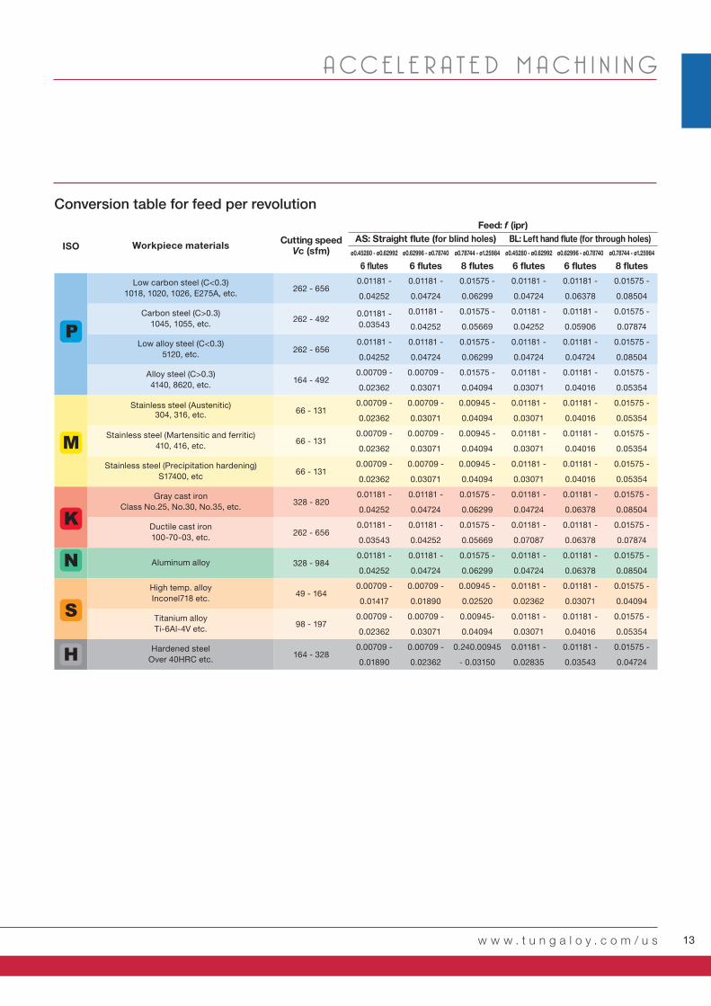
Conversion table for feed per tooth
13w w w . t u n g a l o y . c o m / u s
A CC E L E R A T E D M A C H I N I N G
ISOø0.45280 - ø0.62992 ø0.62996 - ø0.78740 ø0.78744 - ø1.25984 ø0.45280 - ø0.62992 ø0.62996 - ø0.78740 ø0.78744 - ø1.25984
262 - 6560.01181 -
0.04252
0.01181 -
0.04724
0.01575 -
0.06299
0.01181 -
0.04724
0.01181 -
0.06378
0.01575 -
0.08504
262 - 4920.01181 -
0.03543
0.01181 -
0.04252
0.01575 -
0.05669
0.01181 -
0.04252
0.01181 -
0.05906
0.01575 -
0.07874
262 - 6560.01181 -
0.04252
0.01181 -
0.04724
0.01575 -
0.06299
0.01181 -
0.04724
0.01181 -
0.04724
0.01575 -
0.08504
164 - 4920.00709 -
0.02362
0.00709 -
0.03071
0.01575 -
0.04094
0.01181 -
0.03071
0.01181 -
0.04016
0.01575 -
0.05354
66 - 1310.00709 -
0.02362
0.00709 -
0.03071
0.00945 -
0.04094
0.01181 -
0.03071
0.01181 -
0.04016
0.01575 -
0.05354
66 - 1310.00709 -
0.02362
0.00709 -
0.03071
0.00945 -
0.04094
0.01181 -
0.03071
0.01181 -
0.04016
0.01575 -
0.05354
66 - 1310.00709 -
0.02362
0.00709 -
0.03071
0.00945 -
0.04094
0.01181 -
0.03071
0.01181 -
0.04016
0.01575 -
0.05354
328 - 8200.01181 -
0.04252
0.01181 -
0.04724
0.01575 -
0.06299
0.01181 -
0.04724
0.01181 -
0.06378
0.01575 -
0.08504
262 - 6560.01181 -
0.03543
0.01181 -
0.04252
0.01575 -
0.05669
0.01181 -
0.07087
0.01181 -
0.06378
0.01575 -
0.07874
328 - 9840.01181 -
0.04252
0.01181 -
0.04724
0.01575 -
0.06299
0.01181 -
0.04724
0.01181 -
0.06378
0.01575 -
0.08504
49 - 1640.00709 -
0.01417
0.00709 -
0.01890
0.00945 -
0.02520
0.01181 -
0.02362
0.01181 -
0.03071
0.01575 -
0.04094
98 - 1970.00709 -
0.02362
0.00709 -
0.03071
0.00945-
0.04094
0.01181 -
0.03071
0.01181 -
0.04016
0.01575 -
0.05354
164 - 3280.00709 -
0.01890
0.00709 -
0.02362
0.240.00945
- 0.03150
0.01181 -
0.02835
0.01181 -
0.03543
0.01575 -
0.04724
Low carbon steel (C<0.3)
1018, 1020, 1026, E275A, etc.
Carbon steel (C>0.3)
1045, 1055, etc.
Low alloy steel (C<0.3)
5120, etc.
Alloy steel (C>0.3)
4140, 8620, etc.
Stainless steel (Austenitic)304, 316, etc.
Stainless steel (Martensitic and ferritic)
410, 416, etc.
Stainless steel (Precipitation hardening)
S17400, etc
Gray cast iron
Class No.25, No.30, No.35, etc.
Ductile cast iron
100-70-03, etc.
Aluminum alloy
High temp. alloy
Inconel718 etc.
Titanium alloy
Ti-6Al-4V etc.
Hardened steel
Over 40HRC etc.
Cutting speedVc (sfm)
Workpiece materials
Feed: f (ipr)
AS: Straight fl ute (for blind holes) BL: Left hand fl ute (for through holes)
6 fl utes 6 fl utes 6 fl utes 6 fl utes8 fl utes 8 fl utes
Conversion table for feed per revolution

REAMMEISTER14
FOR BEST PERFORMANCE
First assembly
Indexing
Note: Cutting tools may fracture during use. To avoid injury always use safety precautions such as gloves, shields,
and eye protection.
•Clean the tool holder pocket (Fig. 1)
•Clean the reamer head clamping cone
•Insert the clamping screw into the holder and rotate it 2-3 turns in the clockwise
direction (Fig. 2)
•Clamp the reaming head on the screw. Please note that T8 and T9 connections can be
assembled only in a specific position relative to the screw (rotate the head until locating
the correct position) (Fig. 3)
•Manually rotate the head until feeling a slight torque
•Tighten with the special key (Fig. 4)
•Make sure there is no face gap between the tool holder and the reaming head (Fig. 5)
* For recommended torque for T5 through T9 connections, see the chart on the right
•Release the reaming head with the key, turning in the counterclockwise direction until it
rotates freely
•Rotate another one turn by hand
•Remove the reamer head from the tool. The clamping screw should remain inside!!!
•Clean the pocket of the tool holder (Fig. 1)
•Clean the cone on the new reamer head
•Clamp the reaming head on the screw. Please note that T8 and T9 connections can be
assembled only in a specific position relative to the screw (rotate the head until locating
the correct position) (Fig. 3)
•Manually rotate the reaming head. In the beginning it should rotate without the screw
and then (after 1/6 of a turn) it should engage with the screw. Rotate until it sits firmly
in the pocket. If the screw rotates together with the reaming head from the beginning,
remove the reaming head and open the screw another one turn
•Manually rotate the head until feeling a slight torque
•Tighten with the special key (Fig. 4)
•Make sure that there is no face gap between the tool holder and the reaming head (Fig. 5)
* For recommended torque for T5 through T9 connections, see the chart on the right
T9: 15.5 - 17.0 lb-ftT8: 12.5 - 14.8 lb-ftT7: 9.6 - 11.1 lb-ftT6: 5.9 - 7.4 lb-ftT5: 5.2 - 5.9 lb-ft

15w w w . t u n g a l o y . c o m / u s
A CC E L E R A T E D M A C H I N I N G
0.45276 - 0.53150 0.53154 - 0.62992 0.62996 - 1.02362 1.02366 - 1.25984
Δ = 0.00394 - 0.00787 Δ = 0.00394 - 0.01181 Δ = 0.00394 - 0.01575 Δ = 0.00787 - 0.01969
Δ = 0.00591 - 0.00984 Δ = 0.00787 - 0.01181 Δ = 0.00787 - 0.01969 Δ = 0.00787 - 0.02362
FOR BEST PERFORMANCE
Reaming allowance
•Reaming allowance Δ is the stock material to be removed in the reaming process. For a successful reaming
operation, reaming allowance must be determined with proper considerations. Refer to the table below for
appropriate reaming allowance for various hole diameters and materials. Standard reaming allowance, unless
otherwise required, will be the target diameter +0.0079" for all hole diameter ranges and materials.
•Reaming quality largely depends on the quality of the pre-hole. Pre-holes must have no diameter fluctuation and
good straightness.
Runout control is important to achieve proper reaming process.
Best: less than 5 μ
Acceptable: 5 - 15 μm
Not acceptable: over 15 μm
Δ : Reaming allowance
Δ = øDR - øDP
Workpiece materialHole diemeter (inch)
Steel and cast Iron
Aluminum and brass
Recommended runout control Runout
øDR Reaming
øDP Pre-hole
* If an acceptable runout is not achieved, adjust the runout as follows.
1. Make sure that there is no gap between the faces of the reaming head and
the tool holder.
If there is a gap, use the key and tighten again until the gap disappears.
2. Measure the runout of the cylindrical part for runout measurement on the
upper part of the tool to check the installation accuracy of the tool and the
arbor. If the runout on the cylindrical surface of the tool is bad, remove the tool
from the arbor, clean the tool and the arbor, then remount them and measure
the runout.
Cylindrical part for runout measurement

REAMMEISTER16
S = 100 rpm
F = 3.9 ipm
1.5D or 3D
1
23
FOR BEST PERFORMANCE
Cautions when using 5D and 8D reamers
Without chamfer With chamfer
1. Provide internal chamfer (e.g. 45° x 0.0197") on the hole entrance for smooth reamer engagement. (Best option for using a 5D tool)
*Use the same diameter heads for both piloting and deep reaming processes
2. Make a guide hole with a shorter reamer (1.5D or 3D), then use a long overhang tool. (Best option for using an 8D tool)
In long overhang applications with the length-to-diameter ratios of 5D to 8D, a reamer is prone to chatter due to low
rigidity when entering the hole.
The following methods are recommended for process stability.
1. Use a shorter reamer (1.5D or 3D) to make a guide hole with a
depth of 0.5xD~1xD.
2. Insert the long reamer (8D) in the guide hole rotating at a low speed
(<100 rpm) and feeding slowly (at F = 3.9 ipm) until the reamer
reaches several millimeters from the bottom.
3. Rotate the reamer with the full machining speed and start feeding.
Machine speed
Machining feed
ChatterChatter WithoutWithoutchatterchatter

17w w w . t u n g a l o y . c o m / u s
A CC E L E R A T E D M A C H I N I N G
TRM-T9-R32-5 TRM-T9-R32-5
HRM-1.0630-BL-T9 HRM-1.0630-BL-T9
AH725 AH725
328 295
0.047 0.031
55.7 33.5
0.79 0.59
60
50
40
30
20
10
0
30
20
10
0
PRACTICAL EX AMPLES
Workpiece type
Drill
Insert
Grade
Workpiece material
Results
Cutting speed : Vc (sfm)
Feed : f (ipr)
Feed speed : Vf (ipm)
Drilling depth : H (inch)
Machine
Coolant Internal
Horizontal M/C
80-55-06
Flange yoke
Higher cutting speed and feed rates are attainable with ReamMeister over current brazed reamer due to coated insert and optimal edge geometry. 9 times higher productivity is possible with ReamMeister.
Cu
ttin
gc
on
dit
ion
s
Fe
ed
sp
ee
dV
f (ip
m)
Productivity Productivity 9 times!9 times!
Internal
Horizontal M/C
1045
Flange yoke
Higher cutting speed and feed rates are attainable with ReamMeister over current brazed reamer due to coated insert and optimal edge geometry. 1.5 times longer tool life is possible with ReamMeister.
Tool lifeTool life1.5 times!1.5 times!
To
ol life
(ft
/ in
se
rt)
Competitor Competitor

REAMMEISTER18
MEMO

Check our site and our App to get more info!

Distributed by:
Dec. 2019 (TJ)
Scan for instant web access
facebook.com/tungaloyamer icatwit ter.com/tungaloyinstagram.com/tungaloyamer ica
follow us at:
w w w . t u n g a l o y . c o m / u s
www.youtube.com/tungaloycorporation
To see this product in action visit:
Tungaloy America, Inc.3726 N Ventura Drive, Arlington Heights, IL 60004, U.S.A.
Inside Sales: +1-888-554-8394
Technical Support: +1-888-554-8391
Fax: +1-888-554-8392www.tungaloy.com/us
Tungaloy Canada432 Elgin St. Unit 3, Brantford, Ontario N3S 7P7, CanadaPhone: +1-519-758-5779 Fax: +1-519-758-5791
www.tungaloy.com/ca
Tungaloy de Mexico S.A.C Los Arellano 113, Parque Industrial Siglo XXIAguascalientes, AGS, Mexico 20290Phone:+52-449-929-5410 Fax:+52-449-929-5411
www.tungaloy.com/mx