TuffCam™ Swing Clamps - Vektek€¦ · ©Vektek, February 2017 800-992-0236 When do you recommend...
24
© Vektek, February 2017 800-992-0236 www.vektek.com When do you recommend the use of TuffCam™ Swing Clamps over the standard product? Applications where speed is essential, massive arms are required, or position sensing is necessary, use the TuffCam™ design most effectively. When speed is essential, standard Swing Clamps (which last millions of cycles in ordinary applications) may not live up to life cycle expectations. If a standard Swing Clamp is damaged early in its life due to speed abuse, replacement with a TuffCam™ Swing Clamp may be a way to maintain speed requirements and lengthen device life. Where arm mass damages the swing mechanism of standard Swing Clamps, the tri-cam design of TuffCam™ strengthens the ball and cam link. The beefier design, capacity, and reinforced rotation mechanism of the TuffCam™ could be your best solution. Can I run the TuffCam™ Swing Clamp at any speed I want? No, there are restrictions. TuffCam™ Swing Clamps are capable of approximately two times the speed of standard Swing Clamps in prolonged use without damage. In the event that you need faster speeds or larger arms, please understand that the life of even TuffCam™ Swing Clamps is reduced. Consult the Clamp Time and Flow Rate chart on page C-2 to determine the maximum speed for your application. What makes the cam follower ball seat so special in these units? The three cams and cam balls guide the rotation of the plunger providing greater support and directional stability. The patented cam follower design is unique in the industry and uses solid carbide balls and composite ball seats. The ball seat design assures that the ball rolls in the cam rather than jamming and scraping resulting in wear on both the cam track and ball. The demands on my fixture have changed and I am considering your TuffCam™ Swing Clamps. Can I switch out TuffCam™ for your standard product? Yes, the TuffCam™ Swing Clamps have the same mounting envelope as their standard swing clamp counterparts. I want to use Work Supports with TuffCam™Swing Clamps. Will the Work Supports cycle fast enough to keep up with the part change outs? There will be some lag between the unclamp of Swing Clamps and the full release of pressure in any work support circuit. This is critical with fluid advance supports. The circuit must have time to evacuate under low pressure to allow the plungers to retract for reloading the fixture. If speed is the issue in support retraction coordinating with TuffCam™, an air advance support must be used with the air circuit released prior to hydraulic circuit release. When the hydraulic circuit is released, the support will begin to immediately retract pushing only the air from the line rather than the higher viscosity hydraulic fluid. I’m using a high-volume pump and it is “blowing out” my Swing Clamps. Will TuffCam™ Swing Clamps take care of this problem? High-volume pumps often incorporate high-volume accumulators. An accumulator will yield excessive flow, approaching instantaneous infinite flow, and is intended for dynamic loads. Hydraulic clamps are used to hold static loads. Excessive flow may continue to damage clamps, even TuffCam™ clamps. We recommend changing to a pump designed for clamping applications restrict flow to the table on page C-2. My applications requires clamps to hit my part in the exact place every time. Should I use your TuffCam™ Swing Clamps? TuffCam™ Swing Clamps will be more precise in their point of contact. Keep in mind that any draft angle or side forces will ultimately damage the cam tracks of any Swing Clamp and result in loss of precision. In the case of precision positioning, guide pins are recommended and may be implemented with a single-ended or double-ended arm. What defines a TuffCam™ Swing Clamp? The single direction, tri-cam design of TuffCam™produces the strength and reliability to support faster speeds and larger arms. This design also delivers noticeably better accuracy and repeatability over other brands. The clocking feature, included on all styles, dramatically reduces the time it takes to change arms for maintenance, replacement or design setup. How can I measure the clamp speed? The maximum speed of a Swing Clamp is applicable to both clamp and unclamp function, as the momentum on the cam track and cam follower apply to both movements. To approximate the speed of your application: * Look down the centerline of the swing clamp, perpendicular to the arm. * Actuate your clamping system while watching the arm “swing” into position. * The eye can track speed of movement at roughly 1/16 second. If while looking directly into the end of the Swing Clamp, you can observe the arm move through its swing, the positioning time should be somewhere around ½ second or longer. See flow rates and clamping time on page C-2. * If, while looking directly into the end of the Swing Clamp, you cannot observe the arm move, or it is unclamped and the next thing you can see is the device is in the clamped position, the positioning time is something substantially less than 1/2 second. Your standard model clamp is at risk of premature failure. However, the TuffCam™ Swing Clamps can actuate at a faster speed. See flow rates and clamping time on page C-2. * It is possible to approximate the clamp time by adding the total active volume of devices in the specific control branch of your system, and dividing that volume (cubic inches) by your pump’s output volume (cubic inches per minute) and then multiply that number by 60 (60 seconds per minute). This will give you the theoretical calculated time to move a device through its stroke, but does not account for flow loss due to restrictions in the system. *TuffCam™ is a trademark of Vektek LLC TuffCam™ Swing Clamps Frequently Asked Questions C-1
Transcript of TuffCam™ Swing Clamps - Vektek€¦ · ©Vektek, February 2017 800-992-0236 When do you recommend...

© Vektek, February 2017 800-992-0236 www.vektek.com
When do you recommend the use of TuffCam™ Swing Clamps over the standard product? Applications where speed is essential, massive arms are required, or position sensing is necessary, use the TuffCam™ design most effectively. When speed is essential, standard Swing Clamps (which last millions of cycles in ordinary applications) may not live up to life cycle expectations. If a standard Swing Clamp is damaged early in its life due to speed abuse, replacement with a TuffCam™ Swing Clamp may be a way to maintain speed requirements and lengthen device life. Where arm mass damages the swing mechanism of standard Swing Clamps, the tri-cam design of TuffCam™ strengthens the ball and cam link. The beefier design, capacity, and reinforced rotation mechanism of the TuffCam™ could be your best solution.
Can I run the TuffCam™ Swing Clamp at any speed I want? No, there are restrictions. TuffCam™ Swing Clamps are capable of approximately two times the speed of standard Swing Clamps in prolonged use without damage. In the event that you need faster speeds or larger arms, please understand that the life of even TuffCam™ Swing Clamps is reduced. Consult the Clamp Time and Flow Rate chart on page C-2 to determine the maximum speed for your application.
What makes the cam follower ball seat so special in these units? The three cams and cam balls guide the rotation of the plunger providing greater support and directional stability. The patented cam follower design is unique in the industry and uses solid carbide balls and composite ball seats. The ball seat design assures that the ball rolls in the cam rather than jamming and scraping resulting in wear on both the cam track and ball.
The demands on my fixture have changed and I am considering your TuffCam™ Swing Clamps. Can I switch out TuffCam™ for your standard product? Yes, the TuffCam™ Swing Clamps have the same mounting envelope as their standard swing clamp counterparts.
I want to use Work Supports with TuffCam™Swing Clamps. Will the Work Supports cycle fast enough to keep up with the part change outs? There will be some lag between the unclamp of Swing Clamps and the full release of pressure in any work support circuit. This is critical with fluid advance supports. The circuit must have time to evacuate under low pressure to allow the plungers to retract for reloading the fixture. If speed is the issue in support retraction coordinating with TuffCam™, an air advance support must be used with the air circuit released prior to hydraulic circuit release. When the hydraulic circuit is released, the support will begin to immediately retract pushing only the air from the line rather than the higher viscosity hydraulic fluid.
I’m using a high-volume pump and it is “blowing out” my Swing Clamps. Will TuffCam™ Swing Clamps take care ofthis problem? High-volume pumps often incorporate high-volume accumulators. An accumulator will yield excessive flow, approaching instantaneous infinite flow, and is intended for dynamic loads. Hydraulic clamps are used to hold static loads. Excessive flow may continue to damage clamps, even TuffCam™ clamps. We recommend changing to a pump designed for clamping applications restrict flow to the table on page C-2.
My applications requires clamps to hit my part in the exact place every time. Should I use your TuffCam™ Swing Clamps? TuffCam™ Swing Clamps will be more precise in their point of contact. Keep in mind that any draft angle or side forces will ultimately damage the cam tracks of any Swing Clamp and result in loss of precision. In the case of precision positioning, guide pins are recommended and may be implemented with a single-ended ordouble-ended arm.
What defines a TuffCam™ Swing Clamp? The single direction, tri-cam design of TuffCam™produces the strength and reliability to support faster speeds and larger arms. This design also delivers noticeably better accuracy and repeatability over other brands. The clocking feature, included on all styles, dramatically reduces the time it takes to change arms for maintenance, replacement or design setup.
How can I measure the clamp speed? The maximum speed of a Swing Clamp is applicable to both clamp and unclamp function, as the momentum on the cam track and cam follower apply to both movements. To approximate the speed of your application:
* Look down the centerline of the swingclamp, perpendicular to the arm.
* Actuate your clamping system whilewatching the arm “swing” into position.
* The eye can track speed of movement atroughly 1/16 second. If while lookingdirectly into the end of the Swing Clamp,you can observe the arm move throughits swing, the positioning time should besomewhere around ½ second or longer.See flow rates and clamping time onpage C-2.
* If, while looking directly into the end ofthe Swing Clamp, you cannot observethe arm move, or it is unclamped and thenext thing you can see is the device is inthe clamped position, the positioningtime is something substantially less than1/2 second. Your standard model clampis at risk of premature failure. However,the TuffCam™ Swing Clamps can actuateat a faster speed. See flow rates andclamping time on page C-2.
* It is possible to approximate the clamptime by adding the total active volume ofdevices in the specific control branch ofyour system, and dividing that volume(cubic inches) by your pump’s outputvolume (cubic inches per minute) andthen multiply that number by 60(60 seconds per minute). This will giveyou the theoretical calculated time tomove a device through its stroke, butdoes not account for flow loss due torestrictions in the system.
*TuffCam™ is a trademark of Vektek LLC
TuffCam™ Swing Clamps
Frequently Asked Questions
C-1

www.vektek.com 800-992-0236 © Vektek, February 2017
TuffCam™ Swing Clamps were developed to meet your demand for high-speed, precise positioning and/or heavy arm applications. These tri-cam design clamps can position and clamp in less than one second and handle larger arms than standard Swing Clamps. One of the keys to this innovation is the patented Cam Follower Ball Seat that was developed to improve strength and wear. Using the patented Vektek V-Groove technology, a Tungsten Carbide ball for strength and wear, and an elastomer spring, these clamps have reduced static friction for improved clamp breakaway and reduced dynamic friction for improved life.
Available in these body configurations - Threaded Body - Top Flange - Top Flange Long Stroke - Bottom Flange - Bottom Flange Long Stroke - Cartridge Mount - Rod Position Sensing - Magnetic Position Sensing - Low Profile Top Flange - Low Profile Bottom Flange - Low Profile Rod Position Sensing - Low Profile Magnetic Position SensingSingle and double acting (position sensing are double acting only). Three cams for more accurate arm positioning, smoother rotation, and lower per cam surface contact pressure. Patented ball seat for improved rotary function, cam follower contact, and reduced dynamic and static friction.BHC™ (Black Hard Coating) on the cylinder bodies helps prevent scoring and scratching. Standard fluorocarbon wipers for improved coolant compatibility. Arm clocking feature uses standard Vektek arms. Same mounting envelope as Standard VektorFlo® Swing Clamps.TuffCam™ Clamp Timeand Fluid Flow Rates
Swing Clamp
Capacity(lb.)
Standard Arm Extended ArmFastest
AllowableClamp Time(sec.)
Max. Permissible
Flow Rate
(cu. in./min)
Fastest Allowable
Clamp Time (sec.)
Max. Permissible
Flow Rate
(cu. in./min)
450 0.2 17 0.5 71100 0.3 47 0.7 202600 0.4 109 0.8 545000 0.5 235 1.0 117
Low Profile TuffCam™5000 0.5 155 1.0 787500 0.5 251 1.0 126
ILS150108 REV G
U. S. Patent Nos. 7,032,8975,820,118
TuffCam™ Swing Clamp Arm Clocking Feature Drill points shown in the clamped position.
6 Clocking features 60° apart.
NOTE: Arm Length and Pressure Limitation Graphs on page O-3
TuffCam™ Cam Follower Design - Three cams for more accurate arm positioning, smoother rotation, and lower per cam surface contact pressure - Composite ball seat improves rotary function, cam follower contact, and reduces friction - Tungsten carbide ball material
The flows in the table are maximum recommendations and clamp times are minimum recommendations.- For upreach and double arms, use extended arm flows and times.- When using custom arms the extended arm flows and times are to be considered the limiting factor.- The actual time to position the clamp will vary by custom arm configuration and may require customer testing in specific application to establish limits.
C-2
TuffCam™ Swing Clamps
Features, Clocking, Clamp Time and Flow Rates

© Vektek, March 2018 800-992-0236 www.vektek.com
DimensionsSingle Acting Model No.
Double Acting Model No.
Clamp Capacity (lb.)
A B C D E F G H J N P S T V W Z AC AD14-0105-01- L, R, S 14-0205-01- L, R, S 450 1 1/16-16 4.28 4.02 2.02 0.94 0.75 0.27 0.437 1/4-28 X 0.38 0.57 1.13 0.81 1.50 0.56 N/A 25 SAE 2 0.1314-0109-01- L, R, S 14-0209-01- L, R, S 1100 1 1/2-16 5.68 5.32 2.54 1.27 1.09 0.38 0.625 3/8-24 X 0.63 0.79 1.50 1.03 1.88 0.78 0.09 35 SAE 4 0.1914-0113-01- L, R, S 14-0213-01- L, R, S 2600 1 7/8-16 7.33 6.81 3.35 1.30 1.06 0.36 0.875 1/2-20 X 0.75 1.16 1.88 1.20 2.25 0.97 0.08 30 SAE 4 0.19
WARNING! Never allow swing arm to contact workpiece or fixture during arm rotation. ** Cylinder capacities are listed at 5,000 psi maximum operating pressure, with a standard length VektorFlo® arm installed. Minimum operating pressure is 750 psi for single acting, 500 psi for double acting. The clamping force is adjustable by varying the hydraulic system pressure. To determine the approximate output force for your application, divide the cylinder capacity shown above by 5,000, and multiply the Resultant Number by Your System Operating Pressure to obtain the approximate clamping force for your application. (Actual force will vary slightly due to internal cantilever loading, friction loss and/or return springs.)*** To allow for piece part height variations, it is recommended that the vertical travel be set at about 50% of the vertical stroke. **** To ensure maximum service life and trouble-free operation, restrict fluid flow per table on page C-2.
Model No.
Clamp Swing
Direction
Cylinder Capacity
(lb.)**
Vertical Clamp Stroke (in)***
Total Stroke(Swing
+ Vertical)
BodyThread
Standard Arm
Length**
Effective Piston Area
(sq. in.)
OilCapacity (cu. in.)****
Retract Extend RetractSingle Acting (S/A) Cylinders, actuated hydraulically 1 direction, spring returned.14-0105-01-R Right
450.22
0.57 1 1/16-16 1.06 0.098 N/A 0.05614-0105-01-L Left .2214-0105-01-S Straight .5714-0109-01-R Right
1100.31
0.79 1 1/2-16 1.50 0.295 N/A 0.23314-0109-01-L Left .3114-0109-01-S Straight .7914-0113-01-R Right
2600.50
1.16 1 7/8-16 2.00 0.626 N/A 0.72614-0113-01-L Left .5014-0113-01-S Straight 1.16Double Acting (D/A) Cylinders, actuated hydraulically both directions.14-0205-01-R Right
450.22
0.57 1 1/16-16 1.06 0.098 0.142 0.05614-0205-01-L Left .2214-0205-01-S Straight .5714-0209-01-R Right
1100.31
0.79 1 1/2-16 1.50 0.295 0.475 0.23314-0209-01-L Left .3114-0209-01-S Straight .7914-0213-01-R Right
2600.50
1.16 1 7/8-16 2.00 0.626 1.423 0.72614-0213-01-L Left .5014-0213-01-S Straight 1.16
U. S. Patent No. 7,032,897
ILS140001 REV M
SWING CLAMP PLUNGER SHOWN IN THE EXTENDED LH CAM POSITION
SINGLE ACTING DOUBLE ACTING
Single And Double Actingn Available in three capacities 450, 1,100 and 2,600 lb. n Three cams for accurate arm positioning, smoother rotation and lower per cam surface contact pressure.n Patented ball seat for improved rotary function, cam follower contact and reduced dynamic and static friction.n Fluorocarbon wipers are standard for improved coolant compatibility.nStandard swing is 90°; swing angles less than 90° require Swing Restrictors (Page C-32). Swings angles greater than 90°are special order products.n To avoid cylinder damage and preserve warranty, use recommended flow rate limits and time calculations on page C-2.n Tungsten Carbide ball for improved strength and wear.n Same mounting envelope as VersaCam™ Swing Clamps.n Arms sold separately – see section O.
C-3
TuffCam™ Swing Clamps
Threaded Body

www.vektek.com 800-992-0236 © Vektek, March 2018
DimensionsSingle Acting Model No.
Double Acting Model No.
Clamp Capacity (lb.)
A B C D E F G H J N P S T V W Z AC AD14-0105-01- L, R, S 14-0205-01- L, R, S 450 1 1/16-16 4.28 4.02 2.02 0.94 0.75 0.27 0.437 1/4-28 X 0.38 0.57 1.13 0.81 1.50 0.56 N/A 25 SAE 2 0.1314-0109-01- L, R, S 14-0209-01- L, R, S 1100 1 1/2-16 5.68 5.32 2.54 1.27 1.09 0.38 0.625 3/8-24 X 0.63 0.79 1.50 1.03 1.88 0.78 0.09 35 SAE 4 0.1914-0113-01- L, R, S 14-0213-01- L, R, S 2600 1 7/8-16 7.33 6.81 3.35 1.30 1.06 0.36 0.875 1/2-20 X 0.75 1.16 1.88 1.20 2.25 0.97 0.08 30 SAE 4 0.19
H
D
CB
F
.156±.005
G
P
S TYP
T
2x Z
J PLUNGER THREAD
ATHREAD
E
N TOTAL STROKEM CLAMP STROKE
WTYP
V
ILS140002 REV K
SWING CLAMP PLUNGER SHOWN IN THE EXTENDED LH CAM POSITION
ORDER ARMSEPARATELY
6x AD x 90ARM CLOCKING FEATURE
AC CLAMP PORTAC PORTUNCLAMP- D/A VENT- S/A,BREATHER PROVIDED
Order arms separately.
FeaturesBHC™ (Black Hard Coating) on the cylinder bodies helps prevent scoring and scratching.
SAE porting is all on the top of the cylinder body for easy access (bottom unclamp porting is available).
Vent port with bronze filter gives single acting Swing Clamps a place to “breathe” and helps keep out contamination.
Single Acting Model No.
Double Acting Model No. M
14-0105-01-L 14-0205-01-L .2214-0105-01-R 14-0205-01-R .2214-0105-01-S 14-0205-01-S .5714-0109-01-L 14-0209-01-L .3114-0109-01-R 14-0209-01-R .3114-0109-01-S 14-0209-01-S .7914-0113-01-L 14-0213-01-L .5014-0113-01-R 14-0213-01-R .5014-0113-01-S 14-0213-01-S 1.16
Single Acting Cylinders, actuated hydraulically one direction, spring returned.
Double Acting Cylinders, actuated hydraulically both directions.
C-4
TuffCam™ Swing Clamps
Threaded Body

© Vektek, March 2018 800-992-0236 www.vektek.com
DimensionsSingle Acting Model No.
Double Acting Model No.
Clamp Capacity (lb.)
A B C D E F G H J K L N P Q R S T U V X Y Z AC AD
14-6105-01- L, R, S 14-6205-01- L, R, S 450 .99 4.28 4.02 2.02 .94 .75 .31 .437 1/4-28 X .38 .22 .63 .57 1.88 .80 .22 .96 1.58 .31 .58 .69 .44
28
SAE 2 .1314-6109-01- L, R, S 14-6209-01- L, R, S 1100 1.43 5.68 5.32 2.60 1.21 1.03 .38 .625 3/8-24 X .63 .28 .84 .79 2.31 1.03 .34 1.24 2.08 .50 .76 .88 .56 SAE 4 .1914-6113-01- L, R, S 14-6213-01- L, R, S 2600 1.74 7.34 6.82 3.35 1.30 1.06 .41 .875 1/2-20 X .75 .34 1.05 1.16 2.69 1.25 .44 1.53 2.53 .41 .90 1.00 .53 SAE 4 .1914-6118-02- L, R, S 14-6218-02- L, R, S 5000 2.37 9.92 9.29 4.41 1.80 1.47 .54 1.250 5/8-18 X .75 .41 1.41 1.65 3.61 1.72 .60 2.05 3.34 .75 1.21 1.37 .75 SAE 4 .19
Model No.Clamp Swing
Direction
Cylinder Capacity
(lb.)**
Vertical Clamp Stroke (in.)***
Total Stroke(Swing
+ Vertical)
BodyDia.
Standard Arm
Length**
Effective Piston Area
(sq. in.)
OilCapacity (cu. in.)****
Optional Flow Control Model No.
*****Retract Extend RetractSingle Acting (S/A) Cylinders, actuated hydraulically 1 direction, spring returned.14-6105-01-R Right
450.22
0.57 0.99 1.06 0.098 N/A 0.056 70-2037-7014-6105-01-L Left .2214-6105-01-S Straight .5714-6109-01-R Right
1100.31
0.79 1.43 1.50 0.295 N/A 0.233 70-2037-7114-6109-01-L Left .3114-6109-01-S Straight .7914-6113-01-R Right
2600.50
1.16 1.74 2.00 0.626 N/A 0.726 70-2037-7114-6113-01-L Left .5014-6113-01-S Straight 1.1614-6118-02-R Right
5000.62
1.65 2.37 2.50 1.178 N/A 1.955 70-2037-7214-6118-02-L Left .6214-6118-02-S Straight 1.65Double Acting (D/A) Cylinders, actuated hydraulically both directions.14-6205-01-R Right
450.22
0.57 0.99 1.06 0.098 0.142 0.056 70-2037-7014-6205-01-L Left .2214-6205-01-S Straight .5714-6209-01-R Right
1100.31
0.79 1.43 1.50 0.295 0.475 0.233 70-2037-7114-6209-01-L Left .3114-6209-01-S Straight .7914-6213-01-R Right
2600.50
1.16 1.74 2.00 0.626 1.423 0.726 70-2037-7114-6213-01-L Left .5014-6213-01-S Straight 1.1614-6218-02-R Right
5000.62
1.65 2.37 2.50 1.178 3.992 1.955 70-2037-7214-6218-02-L Left .6214-6218-02-S Straight 1.65
Single And Double Actingn Three cams for accurate arm positioning, smoother
rotation and lower per cam surface contact pressure.n Patented ball seat for improved rotary function,
cam follower contact and reduced dynamic andstatic friction.
n Fluorocarbon wipers are standard for improvedcoolant compatibility.
n Tungsten Carbide ball material for strength and wear.n Same mounting envelope as standard VektorFlo®
Swing Clamps.n Manifold fitting Model No. 30-8711-20, adapter
assembly and plugs are included and shipped withthe clamp. See section H.
n TuffCam™ Clocking feature (page C-2).n Arms sold separately – see section O.n Can be manifold mounted or plumbed (use standard SAE). U. S. Patent No.
7,032,897
WARNING! Never allow swing arm to contact workpiece or fixture during arm rotation. ** Cylinder capacities are listed at 5,000 psi maximum operating pressure, with a standard length VektorFlo® arm installed.
Minimum operating pressure is 750 psi for single acting, 500 psi for double acting. The clamping force is adjustable by varying the hydraulic system pressure. To determine the approximate output force for your application, divide the cylinder capacity shown above by 5,000, and multiply the Resultant Number by Your System Operating Pressure to obtain the approximate clamping force for your application. (Actual force will vary slightly due to internal cantilever loading, friction loss and/or return springs.)
*** To allow for piece part height variations, it is recommended that the vertical travel be set at about 50% of the vertical stroke.
ILS146001 REV Q
SWING CLAMP PLUNGER SHOWN IN THE EXTENDED LH CAM POSITION
SINGLE ACTING DOUBLE ACTING
Optional in-port flow control is a meter-in device with reverse free flow check valve.
**** To ensure maximum service life and trouble-free operation, restrict fluid flow per table on page C-2.
***** In-port flow control requires the use of manifold ports.
C-5
TuffCam™ Swing Clamp
Top Flange

www.vektek.com 800-992-0236 © Vektek, March 2018
DimensionsSingle ActingModel No.
Double ActingModel No.
Clamp Capacity (lb.)
A B C D E F G H J K L N P Q R S T U V X Y Z AC AD
14-6105-01- L, R, S 14-6205-01- L, R, S 450 .99 4.28 4.02 2.02 .94 .75 .31 .437 1/4-28 X .38 .22 .63 .57 1.88 .80 .22 .96 1.58 .31 .58 .69 .44
28
SAE 2 .1314-6109-01- L, R, S 14-6209-01- L, R, S 1100 1.43 5.68 5.32 2.60 1.21 1.03 .38 .625 3/8-24 X .63 .28 .84 .79 2.31 1.03 .34 1.24 2.08 .50 .76 .88 .56 SAE 4 .1914-6113-01- L, R, S 14-6213-01- L, R, S 2600 1.74 7.34 6.82 3.35 1.30 1.06 .41 .875 1/2-20 X .75 .34 1.05 1.16 2.69 1.25 .44 1.53 2.53 .41 .90 1.00 .53 SAE 4 .1914-6118-02- L, R, S 14-6218-02- L, R, S 5000 2.37 9.92 9.29 4.41 1.80 1.47 .54 1.250 5/8-18 X .75 .41 1.41 1.65 3.61 1.72 .60 2.05 3.34 .75 1.21 1.37 .75 SAE 4 .19
A
U
GF
E
DC
B
H
M CLAMP STROKEN TOTAL STROKE
P
X
T
STYP
YQ
R
2x Z L
K THRU3 PLACES
.156
.005
V
ILS146002 REV M
ORDER ARMSEPARATELY
6x AD x 90ARM CLOCKING FEATURE
J PLUNGER THREAD
AC PORTUNCLAMP- D/A
VENT- S/A,BREATHER PROVIDED AC CLAMP OR FLOW
CONTROL PORT
BOTTOM CLAMP PORTFOR MANIFOLD MOUNTING(ADAPTER FURNISHED)
BOTTOM UNCLAMP PORTFOR MANIFOLD MOUNTING
(ADAPTER FURNISHED)
SWING CLAMP PLUNGER SHOWN IN THE EXTENDED LH CAM POSITION
Order arms separately.
Mounting DimensionsModel No. A B C D E F G
14-6X05-01- L, R, S 1.015 10-32 0.795 0.219 0.687 0.438 0.62514-6X09-01- L, R, S 1.453 1/4-20 1.032 0.344 0.875 0.562 0.84414-6X13-01- L, R, S 1.765 5/16-18 1.250 0.438 1.000 0.531 1.04714-6X18-02- L, R, S 2.390 3/8-16 1.719 0.601 1.367 0.750 1.406
FeaturesBHC™ (Black Hard Coating) on the cylinder body helps prevent scoring and scratching.
SAE porting is all on the top of the cylinder body for easy access, no need to modify fixtures or reroute tubing to access cylinder end to unclamp. (Optional bottom porting available.)
Vent port with bronze filter gives single acting Swing Clamps a place to “breathe” and helps keep contamination from entering breather port.
A .0102X E .005
2X D .005
2X G .010
2X F .010
C .005
ILS146005 REV C
3X B
.09/.13 CLAMP FEED HOLEFOR MANIFOLD MOUNT
.09/.13 UNCLAMP FEED HOLEFOR DOUBLE ACTING APPLICATIONS
CHAMFER .030 X 45
Single Acting Model No.
Double Acting Model No. M
14-6105-01-L 14-6205-01-L .2214-6105-01-R 14-6205-01-R .2214-6105-01-S 14-6205-01-S .5714-6109-01-L 14-6209-01-L .3114-6109-01-R 14-6209-01-R .3114-6109-01-S 14-6209-01-S .7914-6113-01-L 14-6213-01-L .5014-6113-01-R 14-6213-01-R .5014-6113-01-S 14-6213-01-S 1.1614-6118-02-L 14-6218-01-L .6214-6118-02-R 14-6218-01-R .6214-6118-02-S 14-6218-01-S 1.65
For proper sealing, mating surface must be flat within 0.003 in. with a maximum 63 µin. Ra surface finish.
C-6
TuffCam™ Swing Clamp
Top Flange

© Vektek, March 2018 800-992-0236 www.vektek.com
Model No.*
Clamp Swing
Direction
Cylinder Capacity
(lb.)**
Vertical Clamp Stroke (in.)***
Total Stroke(Swing
+ Vertical)
BodyDia.
Standard Arm
Length**
Effective Piston Area
(sq. in.)
OilCapacity (cu. in.)****
Optional Flow Control Model No.
*****Retract Extend RetractDouble Acting (D/A) Cylinders, actuated hydraulically both directions.14-6209-10-R Right
1100.75 .75 1.21 1.43 1.50 0.295 0.73 0.36 70-2037-7114-6209-10-L Left
14-6209-10-S Straight 1.2114-6213-10-R Right
26001.34 1.34 2.00 1.87 2.00 0.626 2.45 1.25 70-2037-7114-6213-10-L Left
14-6213-10-S Straight 2.00
DimensionsModel No.
Capacity(lb.)
A B C D E F G H J K L N P Q R S T U V X Y Z AC AD
Double Acting (D/A) Cylinders, actuated hydraulically both directions.14-6209-10- L, R, S 1100 1.43 6.93 6.57 3.44 1.21 1.03 0.38 0.625 3/8-24 x 0.63 0.28 0.84 1.21 2.31 1.03 0.34 1.24 2.08 0.50 0.76 0.88 0.56 28 SAE 4 0.1914-6213-10- L, R, S 2600 1.87 9.80 9.28 4.98 1.30 1.06 0.41 0.875 1/2-20 x 0.75 0.34 1.05 2.00 2.71 1.25 0.47 1.53 2.58 0.41 0.95 1.05 0.75 28 SAE 4 0.19
U. S. Patent No. 7,032,897
Double Acting Long Stroken Available in 1,100 and 2,600 lb. capacities.n More than double the vertical clamping stroke for maximum part deviation allowance and swing clearance.n Three cams for accurate arm positioning, smoother rotation and lower per cam surface contact pressure.n Patented ball seat for improved rotary function, cam follower contact, and reduced dynamic and static friction.n Fluorocarbon wipers are standard for improved coolant compatibility.n Tungsten Carbide ball material for strength and wear.n TuffCam™ Clocking feature (page C-2) uses standard length Vektek arm.n Arms sold separately – see section O.
WARNING! Never allow swing arm to contact workpiece or fixture during arm rotation.
* 2,600 lb. Long Stroke are not interchangeable with TuffCam™ or VersaCam™ Swing Clamp models. Check overall dimensions for correct mounting in fixture. ** Cylinder capacities are listed at 5,000 psi maximum operating pressure, with a standard length VektorFlo® arm installed. Minimum operating pressure is 750 psi for single acting, 500 psi for double acting. The clamping force is adjustable by varying the hydraulic system pressure. To determine the approximate output force for your application, divide the cylinder capacity shown above by 5,000, and multiply the Resultant Number by Your System Operating Pressure to obtain the approximate clamping force for your application. (Actual force will vary slightly due to internal cantilever loading, friction loss and/or return springs.)*** To allow for piece part height variations, it is recommended that the vertical travel be set at about 50% of the vertical stroke. **** To ensure maximum service life and trouble-free operation, restrict fluid flow per table on page C-2.***** In-port flow control requires the use of manifold ports.
ILS146006 REV F
SWING CLAMP PLUNGER SHOWN IN THE EXTENDED LH CAM POSITION
Optional in-port flow control is a meter-in device with reverse free flow check valve.
C-7
TuffCam™ Swing Clamps
Top Flange Long Stroke
www.vektek.com 800-992-0236 © Vektek, March 2018
DimensionsModel No.
Capacity(lb.)
A B C D E F G H J K L N P Q R S T U V X Y Z AC AD
Double Acting (D/A) Cylinders, actuated hydraulically both directions.14-6209-10- L, R, S 1100 1.43 6.93 6.57 3.44 1.21 1.03 0.38 0.625 3/8-24 x 0.63 0.28 0.84 1.21 2.31 1.03 0.34 1.24 2.08 0.50 0.76 0.88 0.56 28 SAE 4 0.1914-6213-10- L, R, S 2600 1.87 9.80 9.28 4.98 1.30 1.06 0.41 0.875 1/2-20 x 0.75 0.34 1.05 2.00 2.71 1.25 0.47 1.53 2.58 0.41 0.95 1.05 0.75 28 SAE 4 0.19
A
U
G
F
E
D
C
B
H
M CLAMP STROKEN TOTAL STROKE
P
X
T
STYP
YQ
R
2x Z
L
K THRU3 PLACES
.156
.005
V
ILS146007 REV G
ORDER ARMSEPARATELY
6x AD x 90ARM CLOCKING FEATURE
J PLUNGER THREAD
AC UNCLAMP PORT
AC CLAMP OR FLOWCONTROL PORT
BOTTOM CLAMP PORTFOR MANIFOLD MOUNTING(ADAPTER FURNISHED)
BOTTOM UNCLAMP PORTFOR MANIFOLD MOUTING
(ADAPTER FURNISHED)
SWING CLAMP PLUNGER SHOWN IN THE EXTENDED LH CAM POSITION
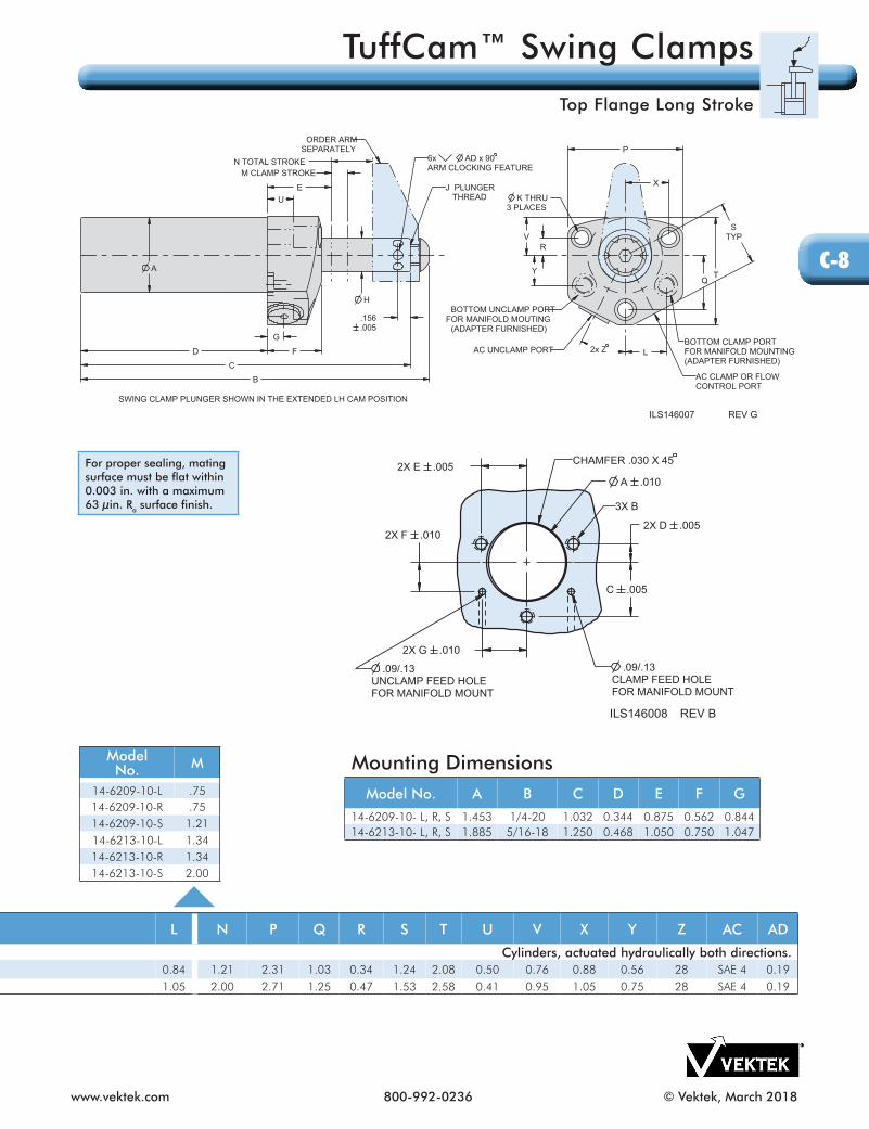
A .0102X E .005
2X D .005
2X G .010
2X F .010
C .005
ILS146008 REV B
3X B
.09/.13 CLAMP FEED HOLEFOR MANIFOLD MOUNT
.09/.13 UNCLAMP FEED HOLEFOR MANIFOLD MOUNT
CHAMFER .030 X 45
Mounting DimensionsModel No. A B C D E F G
14-6209-10- L, R, S 1.453 1/4-20 1.032 0.344 0.875 0.562 0.84414-6213-10- L, R, S 1.885 5/16-18 1.250 0.468 1.050 0.750 1.047
For proper sealing, mating surface must be flat within 0.003 in. with a maximum 63 µin. Ra surface finish.
ModelNo. M
14-6209-10-L .7514-6209-10-R .7514-6209-10-S 1.2114-6213-10-L 1.3414-6213-10-R 1.3414-6213-10-S 2.00
C-8
TuffCam™ Swing Clamps
Top Flange Long Stroke

© Vektek, March 2018 800-992-0236 www.vektek.com
Model No.Clamp Swing
Direction
Cylinder Capacity
(lb.)**
Vertical ClampStroke (in.)***
Total Stroke(Swing
+ Vertical)
Standard Arm
Length
Effective Piston Area
(sq. in.)
OilCapacity (cu. in.)****
Optional Flow
Control Model No.
*****Retract Extend RetractSingle Acting (S/A) Cylinders, actuated hydraulically 1 direction, spring returned.14-2105-01-R Right
450.22.22 .57
0.57 1.06 0.098 N/A 0.056 70-2037-7114-2105-01-L Left14-2105-01-S Straight14-2109-01-R Right
1100.31 .31 .79
0.79 1.50 0.295 N/A 0.233 70-2037-7314-2109-01-L Left14-2109-01-S Straight14-2113-01-R Right
2600.50 .50
1.161.16 2.00 0.626 N/A 0.726 70-2037-7314-2113-01-L Left
14-2113-01-S Straight14-2118-02-R Right
5000.62 .62
1.651.65 2.50 1.178 N/A 1.955 70-2037-7314-2118-02-L Left
14-2118-02-S StraightDouble Acting (D/A) Cylinders, actuated hydraulically both directions.14-2205-01-R Right
450.22 .22 .57
0.57 1.06 0.098 0.142 0.056 70-2037-7114-2205-01-L Left14-2205-01-S Straight14-2209-01-R Right
1100.31 .31 .79
0.79 1.50 0.295 0.475 0.233 70-2037-7314-2209-01-L Left14-2209-01-S Straight14-2213-01-R Right
2600.50 .50
1.161.16 2.00 0.626 1.423 0.726 70-2037-7314-2213-01-L Left
14-2213-01-S Straight14-2218-02-R Right
5000.62 .62
1.651.65 2.50 1.178 3.992 1.955 70-2037-7314-2218-02-L Left
14-2218-02-S Straight
Single And Double Actingn Three cams for accurate arm positioning, smoother rotation and lower per cam surface contact pressure.n Patented ball seat for improved rotary function, cam follower contact, and reduced dynamic and static friction.n Fluorocarbon wipers are standard for improved coolant compatibility. n Tungsten Carbide ball material for strength and wear.n TuffCam™ Clocking feature (page C-2) uses standard length Vektek arm.n Arms sold separately – see section O.
DimensionsSingle Acting Model No.
Double Acting Model No. A B C D E F G H J K L N P Q R T V X Y AC AD
14-2105-01-L, R, S 14-2205-01-L, R, S 1.05 4.32 4.06 2.80 2.99 1.00 0.66 0.438 1/4-28 x 0.375 0.22 0.38 0.57 1.50 1.06 0.38 1.75 0.53 0.59 0.78 SAE 4 0.1314-2109-01-L, R, S 14-2209-01-L, R, S 1.49 5.70 5.33 3.65 3.83 1.25 0.63 0.625 3/8-24 x 0.625 0.28 0.56 0.79 2.00 0.99 0.56 2.50 0.75 0.81 1.13 SAE 4 0.1914-2113-01-L, R, S 14-2213-01-L, R, S 1.79 7.35 6.83 4.43 4.67 1.25 0.63 0.875 1/2-20 x 0.750 0.34 0.75 1.16 2.50 1.21 0.69 3.00 0.94 1.00 1.25 SAE 4 0.1914-2118-02-L, R, S 14-2218-02-L, R, S 2.49 9.92 9.29 5.88 6.20 1.50 0.75 1.250 5/8-18 x 0.750 0.41 0.75 1.65 3.00 2.25 1.06 3.98 1.38 1.19 1.81 SAE 4 0.19
WARNING! Never allow swing arm to contact workpiece or fixture during arm rotation. ** Cylinder capacities are listed at 5,000 psi maximum operating pressure, with a standard length VektorFlo® arm installed. Minimum operating pressure is 750 psi for single acting, 500 psi for double acting. The clamping force is adjustable by varying the hydraulic system pressure. To determine the approximate output force for your application, divide the cylinder capacity shown above by 5,000, and multiply the Resultant Number by Your System Operating Pressure to obtain the approximate clamping force for your application. (Actual force will vary slightly due to internal cantilever loading, friction loss and/or return springs.)*** To allow for piece part height variations, it is recommended that the vertical travel be set at about 50% of the vertical stroke.
ILS142001 REV RSWING CLAMP PLUNGER SHOWN IN THE EXTENDED LH CAM POSITION
SINGLE ACTING DOUBLE ACTING
Optional in-port flow control is a meter-in device with reverse free flow check valve.
**** To ensure maximum service life and trouble-free operation, restrict fluid flow per table on page C-2.***** In-port flow control requires the use of manifold ports.
C-9
TuffCam™ Swing Clamp
Bottom Flange

www.vektek.com 800-992-0236 © Vektek, March 2018
DRAWING NOTES: All ports (except breather) are shipped with removable steel plugs installed. O-ring face seals provided. (SAE 2 ports)* Models 14-2105-01 (L & R) and 14-2205-01 (L & R) are manifold mountable from the bottom SAE 2 port only. ** When used as manifold mounted, all 5 mounting bolts must be used to assure proper o-ring face sealing.
DimensionsSingle Acting Model No.
Double Acting Model No. A B C D E F G H J K L N P Q R T V X Y AC AD
14-2105-01-L, R, S 14-2205-01-L, R, S 1.05 4.32 4.06 2.80 2.99 1.00 0.66 0.438 1/4-28 x 0.375 0.22 0.38 0.57 1.50 1.06 0.38 1.75 0.53 0.59 0.78 SAE 4 0.1314-2109-01-L, R, S 14-2209-01-L, R, S 1.49 5.70 5.33 3.65 3.83 1.25 0.63 0.625 3/8-24 x 0.625 0.28 0.56 0.79 2.00 0.99 0.56 2.50 0.75 0.81 1.13 SAE 4 0.1914-2113-01-L, R, S 14-2213-01-L, R, S 1.79 7.35 6.83 4.43 4.67 1.25 0.63 0.875 1/2-20 x 0.750 0.34 0.75 1.16 2.50 1.21 0.69 3.00 0.94 1.00 1.25 SAE 4 0.1914-2118-02-L, R, S 14-2218-02-L, R, S 2.49 9.92 9.29 5.88 6.20 1.50 0.75 1.250 5/8-18 x 0.750 0.41 0.75 1.65 3.00 2.25 1.06 3.98 1.38 1.19 1.81 SAE 4 0.19
A
BC
DF
H
6x L*
G
N TOTAL STROKEM CLAMP STROKE
.156
.005
P
Q
4x R
2x X
4x Y
T
V
E
ILS142002 REV N
AC PORTUNCLAMP- D/A
VENT- S/ABREATHER PROVIDED
AC CLAMP OR FLOWCONTROL PORT
J PLUNGER THREAD
6x AD x 90ARM CLOCKING FEATURE
ORDER ARMSEPARATELY
5x K**
SWING CLAMP PLUNGER SHOWN IN THE EXTENDED LH CAM POSITION
SAE 2 PORT TOP & BOTTOMCLAMPFOR MANIFOLD MOUNTING*
SAE 2 PORT TOP & BOTTOMUNCLAMP / VENT
FOR MANIFOLD MOUNTING*
For proper sealing, mating surface must be flat within 0.003 in. with a maximum 63 µin. Ra surface finish.
Single Acting Model No.
Double Acting Model No. M
14-2105-01-L 14-2205-01-L .2214-2105-01-R 14-2205-01-R .2214-2105-01-S 14-2205-01-S .5714-2109-01-L 14-2209-01-L .3114-2109-01-R 14-2209-01-R .3114-2109-01-S 14-2209-01-S .7914-2213-01-L 14-2213-01-L .5014-2213-01-R 14-2213-01-R .5014-2213-01-S 14-2213-01-S 1.1614-2118-02-L 14-2218-02-L .6214-2118-02-R 14-2218-02-R .6214-2118-02-S 14-2218-02-S 1.65
C-10
TuffCam™ Swing Clamp
Bottom Flange

© Vektek, March 2018 800-992-0236 www.vektek.com
Model No.*
Clamp Swing
Direction
Cylinder Capacity
(lb.)**
Vertical ClampStroke (in.)***
Total Stroke(Swing
+ Vertical)
Standard Arm
Length**
Effective Piston Area
(sq. in.)
OilCapacity (cu. in.)****
Optional Flow
Control Model No.
*****Retract Extend RetractDouble Acting (D/A) Cylinders, actuated hydraulically both directions.14-2209-10-R Right
1100.75
1.21 1.50 0.295 0.73 0.36 70-2037-7314-2209-10-L Left .75 14-2209-10-S Straight 1.2114-2213-10-R Right
26001.34
2.00 2.00 0.626 2.45 1.25 70-2037-7314-2213-10-L Left 1.3414-2213-10-S Straight 2.00
DimensionsModel No.
Capacity(lb.)
A B C D E F G H J K L N P Q R T V X Y AC AD
Double Acting (D/A) 14-2209-10- L, R, S 1100 1.49 6.97 6.62 4.53 4.70 1.25 0.63 0.625 3/8-24 x 0.625 0.28 0.56 1.21 2.00 0.99 0.56 2.48 0.75 0.81 1.13 SAE 4 0.1914-2213-10- L, R, S 2600 1.87 9.84 9.34 6.10 6.34 1.25 0.63 0.875 1/2-20 x 0.750 0.34 0.75 2.00 2.50 1.21 0.69 2.98 0.94 1.00 1.25 SAE 4 0.19
Double Acting Long Stroken Available in 1,100 and 2,600 lb. capacities.n More than double the vertical clamping stroke for maximum part deviation allowance and swing clearance.n Three cams for accurate arm positioning, smoother rotation and lower per cam surface contact pressure.n Patented ball seat for improved rotary function, cam follower contact, and reduced dynamic and static friction.n Fluorocarbon wipers are standard for improved coolant compatibility.n Tungsten Carbide ball material for strength and wear.n TuffCam™Clocking feature (page C-2) uses standard length Vektek arm.n Arms sold separately – see section O.
U. S. Patent No. 7,032,897
WARNING! Never allow swing arm to contact workpiece or fixture during arm rotation.* 2,600 lb. Long Stroke may not be interchangeable with TuffCam™ or VersaCam™ Swing Clamp models. Check overall dimensions for correct mounting in fixture.** Cylinder capacities are listed at 5,000 psi maximum operating pressure, with a standard length VektorFlo® arm installed. Minimum operating pressure is 750 psi for single acting, 500 psi for double acting. The clamping force is adjustable by varying the hydraulic system pressure. To determine the approximate output force for your application, divide the cylinder capacity shown above by 5,000, and multiply the Resultant Number by Your System Operating Pressure to obtain the approximate clamping force for your application. (Actual force will vary slightly due to internal cantilever loading, friction loss and/or return springs.)*** To allow for piece part height variations, it is recommended that the vertical travel be set at about 50% of the vertical stroke. **** To ensure maximum service life and trouble-free operation, restrict fluid flow per table on C-2.***** In-port flow control requires the use of manifold mount ports.
Optional in-port flow control is a meter-in device with reverse free flow check valve.
ILS142006 REV F
SWING CLAMP PLUNGER SHOWN IN THE EXTENDED LH CAM POSITION
C-11
TuffCam™ Swing Clamps
Bottom Flange Long Stroke

www.vektek.com 800-992-0236 © Vektek, March 2018
DimensionsModel No.
Capacity(lb.)
A B C D E F G H J K L N P Q R T V X Y AC AD
Double Acting (D/A) 14-2209-10- L, R, S 1100 1.49 6.97 6.62 4.53 4.70 1.25 0.63 0.625 3/8-24 x 0.625 0.28 0.56 1.21 2.00 0.99 0.56 2.48 0.75 0.81 1.13 SAE 4 0.1914-2213-10- L, R, S 2600 1.87 9.84 9.34 6.10 6.34 1.25 0.63 0.875 1/2-20 x 0.750 0.34 0.75 2.00 2.50 1.21 0.69 2.98 0.94 1.00 1.25 SAE 4 0.19
For proper sealing, mating surface must be flat within 0.003 in. with a maximum 63 µin. Ra surface finish.
DRAWING NOTES:* All models are shipped with removable steel plugs installed. O-Ring face seals provided.*** All five mounting screws must be used when manifold mounting, to assure a leak-free O-Ring seal.
A
BC
DF
H
6x L
G
N TOTAL STROKE
M CLAMP STROKE
.156
.005
P
Q
4x R
2x X
4x Y
T
V
E
ILS142007 REV H
AC UNCLAMP PORT
AC CLAMP OR FLOWCONTROL PORT
J PLUNGER THREAD
6x AD x 90ARM CLOCKING FEATURE
ORDER ARMSEPARATELY
5x K***
SWING CLAMP PLUNGER SHOWN IN THE EXTENDED LH CAM POSITIONSAE 2 PORT TOP & BOTTOMCLAMPFOR MANIFOLD MOUNTING
SAE 2 PORT TOP & BOTTOMUNCLAMP
FOR MANIFOLD MOUNTING
Model No. M
Double Acting 14-2209-10-L 0.7514-2209-10-R 0.7514-2209-10-S 1.1214-2213-10-L 1.3414-2213-10-R 1.3414-2213-10-S 2.00
C-12
TuffCam™ Swing Clamps
Bottom Flange Long Stroke

© Vektek, March 2018 800-992-0236 www.vektek.com
DimensionsModel No.
Capacity(lb.)
A B C D E F G H J K L M N P R S T V W AC
Single Acting (S/A) Cylinders, actuated hydraulically 1 direction, spring returned.14-1105-01- X 450 1 1/16-12 4.25 4.00 2.12 0.83 0.63 0.49 0.438 1/4-28 x 0.375 0.92 0.935 0.22 0.57 1.00 1.32 0.13 1.25 N/A N/A Breather14-1109-01- X 1100 1 5/8-12 5.66 5.31 2.68 1.13 0.94 0.65 0.625 3/8-24 x 0.625 1.34 1.372 0.31 0.79 1.50 1.50 0.13 1.88 0.02 1.03 Breather14-1113-01- X 2600 1 7/8-12 7.32 6.80 3.15 1.49 1.25 0.55 0.875 1/2-20 x 0.750 1.72 1.747 0.50 1.16 1.63 1.50 0.16 2.13 0.02 1.40 Breather
Double Acting (D/A) Cylinders, actuated hydraulically both directions.14-1205-01- X 450 1 1/6-12 4.25 4.00 2.12 0.83 0.63 0.49 0.438 1/4-28 x 0.375 0.92 0.935 0.22 0.57 1.00 1.32 0.13 1.25 N/A N/A SAE 214-1209-01- X 1100 1 5/8-12 5.66 5.31 2.68 1.13 0.94 0.65 0.625 3/8-24 x 0.625 1.34 1.372 0.31 0.79 1.50 1.50 0.13 1.88 0.02 1.03 SAE 414-1213-01- X 2600 1 7/8-12 7.32 6.80 3.15 1.49 1.25 0.55 0.875 1/2-20 x 0.750 1.72 1.747 0.50 1.16 1.63 1.50 0.16 2.13 0.02 1.40 SAE 4
Model No.
ClampSwing
Cylinder Capacity
(lb.)**
Vertical ClampStroke (in)***
Total Stroke(Swing
+ Vertical)
BodyThread
Standard Arm
Length
Effective Piston Area
(sq. in.)
OilCapacity (cu. in.)****
Retract Extend RetractSingle Acting (S/A) Cylinders, actuated hydraulically 1 direction, spring returned.14-1105-01-R Right
450.22
0.57 1 1/16-12 1.06 0.098 N/A 0.05614-1105-01-L Left .2214-1105-01-S Straight .5714-1109-01-R Right
1100.31
0.79 1 5/8-12 1.50 0.295 N/A 0.23314-1109-01-L Left .3114-1109-01-S Straight .7914-1113-01-R Right
2600.50
1.16 1 7/8-12 2.00 0.626 N/A 0.72614-1113-01-L Left .5014-1113-01-S Straight 1.16
Double Acting (D/A) Cylinders, actuated hydraulically both directions.14-1205-01-R Right
450.22
0.57 1 1/16-12 1.06 0.098 0.142 0.05614-1205-01-L Left .2214-1205-01-S Straight .5714-1209-01-R Right
1100.31
0.79 1 5/8-12 1.50 0.295 0.475 0.23314-1209-01-L Left .3114-1209-01-S Straight .7914-1213-01-R Right
2600.50
1.16 1 7/8-12 2.00 0.626 1.423 0.72614-1213-01-L Left .5014-1213-01-S Straight 1.16
Single And Double Actingn Three cams for accurate arm positioning, smoother rotation and lower per cam surface contact pressure.n Patented ball seat for improved rotary function, cam follower contact, and reduced dynamic and static friction.n Fluorocarbon wipers are standard for improved coolant compatibility.n Tungsten Carbide ball material for strength and wear. n Same mounting envelope as standard VektorFlo® Swing Clamps.n TuffCam™ Clocking feature (page C-2) uses standard length Vektek arm.n Arms sold separately – see section O.nSingle acting models must be vented. Do not install in a blind hole.
Only one o-ring must pass cross porting during installation, and only one (not two) port must be passed (but should not touch), reducing the chance of o-ring damage during in stal la tion.
U. S. Patent No. 7,032,897
WARNING! Never allow swing arm to contact workpiece or fixture during arm rotation. ** Cylinder capacities are listed at 5,000 psi maximum operating pressure, with a standard length VektorFlo® arm installed. Minimum operating pressure is 750 psi for single acting, 500 psi for double acting. The clamping force is adjustable by varying the hydraulic system pressure. To determine the approximate output force for your application, divide the cylinder capacity shown above by 5,000 and multiply the resultant number by your system operating pressure to obtain the approximate clamping force for your application. (Actual force will vary slightly due to internal cantilever loading, friction loss and/or return springs.)*** To allow for piece part height variations, it is recommended that the vertical travel be set at about 50% of the vertical stroke. **** To ensure maximum service life and trouble-free operation, restrict fluid flow per table on page C-2.
ILS141100 REV E
SWING CLAMP PLUNGER SHOWN IN THE EXTENDED LH CAM POSITION
SINGLE ACTING DOUBLE ACTING
C-13
TuffCam™ Swing Clamp
Cartridge Mount

www.vektek.com 800-992-0236 © Vektek, March 2018
R
S
F
G
H
K
L
ATHREAD
PHEX
E
M CLAMP STROKE
N TOTAL STROKE
V
W
T
BC
DILS141101 REV J
SWING CLAMP PLUNGER SHOWN IN THE EXTENDED LH CAM POSITION
ORDER ARMSEPARATELY
CLAMP OILFEED HOLE
AC PORTVENT- S/A*
UNCLAMP- D/AJ PLUNGER THREAD
NOTE: Flexible honing of the cavity is strongly recommended. Flex-Hone™ is a registered trademark of Brush Research Manufacturing Co. Inc., Los Angeles, CA. Please contact Brush Research for additional information. 323-261-2193
* Single Acting models must be vented, do not install in blind holes.
DimensionsModel No.
Capacity(lb.)
A B C D E F G H J K L M N P R S T V W AC
Single Acting (S/A) Cylinders, actuated hydraulically 1 direction, spring returned.14-1105-01- X 450 1 1/16-12 4.25 4.00 2.12 0.83 0.63 0.49 0.438 1/4-28 x 0.375 0.92 0.935 0.22 0.57 1.00 1.32 0.13 1.25 N/A N/A Breather14-1109-01- X 1100 1 5/8-12 5.66 5.31 2.68 1.13 0.94 0.65 0.625 3/8-24 x 0.625 1.34 1.372 0.31 0.79 1.50 1.50 0.13 1.88 0.02 1.03 Breather14-1113-01- X 2600 1 7/8-12 7.32 6.80 3.15 1.49 1.25 0.55 0.875 1/2-20 x 0.750 1.72 1.747 0.50 1.16 1.63 1.50 0.16 2.13 0.02 1.40 Breather
Double Acting (D/A) Cylinders, actuated hydraulically both directions.14-1205-01- X 450 1 1/6-12 4.25 4.00 2.12 0.83 0.63 0.49 0.438 1/4-28 x 0.375 0.92 0.935 0.22 0.57 1.00 1.32 0.13 1.25 N/A N/A SAE 214-1209-01- X 1100 1 5/8-12 5.66 5.31 2.68 1.13 0.94 0.65 0.625 3/8-24 x 0.625 1.34 1.372 0.31 0.79 1.50 1.50 0.13 1.88 0.02 1.03 SAE 414-1213-01- X 2600 1 7/8-12 7.32 6.80 3.15 1.49 1.25 0.55 0.875 1/2-20 x 0.750 1.72 1.747 0.50 1.16 1.63 1.50 0.16 2.13 0.02 1.40 SAE 4
Cavity Dimensions
Model No.
CAThread CB CC CD CE CF
CG DepthCH CJ CK CL CM CN
MIN. MAX.Single Acting (S/A) Cylinders, actuated hydraulically 1 direction, spring returned.14-1105-01-X 1 1/16-12 1.38 1.148 0.979 0.137 0.50 0.750 0.906 1.25 0.938 N/A N/A 0.750 0.41714-1109-01-X 1 5/8-12 2.00 1.713 1.541 0.139 0.68 0.815 0.906 1.50 1.376 N/A N/A 0.815 0.52514-1113-01-X 1 7/8-12 2.25 1.962 1.792 0.139 0.62 0.875 0.906 1.50 1.751 N/A N/A 0.875 0.403Double Acting (D/A) Cylinders, actuated hydraulically both directions.14-1205-01-X 1 1/16-12 1.38 1.148 0.979 0.137 0.50 0.750 0.906 N/A 0.938 2.75 2.25 0.750 0.41714-1209-01-X 1 5/8-12 2.00 1.713 1.541 0.139 0.68 0.815 0.906 N/A 1.376 3.25 2.75 0.815 0.52514-1213-01-X 1 7/8-12 2.25 1.962 1.792 0.139 0.62 0.875 0.906 N/A 1.751 3.75 3.25 0.875 0.403
CK MIN. PLATE THICKNESS D/A ONLY
CL HOLE DEPTH D/A ONLY
CN MIN.
CM MAX.CH MIN. PLATE THICKNESS S/A
CB MIN..010 .005
30° *
CC+.005-.000.005 -A-
15°±1°
CE .007
CJ±.001-A-
45°±5°MINOR CD+.010/-.000 CG,
CA THREAD CF MIN..005 -A-
ILS141102 REV F.218±.062 CLAMPSUPPLY FEED HOLE
BLEND CHAMFERTO BORE
S/A BREATHER HOLE LOCATION;D/A EXTEND SUPPLY LOCATION
63
63
* Basic cavity can be formed with a standard (SAE J1926/1 Port Detail) O-Ring Cutter.
* The 30˚ lead in angle is to ensure trouble free seal installation.
C-14
TuffCam™ Swing Clamp
Cartridge Mount

© Vektek, February 2017 800-992-0236 www.vektek.com
Rod Position Sensing Swing Clamps
Available as TuffCam™ Swing Clamp with capacities of 1,100 lbs. and 2,600 lbs. (excluding Long Stroke models). Actuator Rod Position System can be used with a mechanical switch or air logic system to detect when clamp is in position. Actuator rod is concentric to plunger shaft. Actuator rod moves with the same rotary and linear motion as the plunger. All TuffCam™ features apply to these units. TuffCam™ Clocking feature (page C-2) uses standard length Vektek arm.
BHC™ (Black Hard Coating) on the cylinder body helps prevent scoring and scratching.
Rod Position Sensing SystemModel No.
Clamp Swing
Direction
Cylinder Capacity
(lb.)
A(in.)
B(in.)
C(in.)
Optional Flow Control
Model No.*TuffCam™ Threaded Body (D/A)
Cylinders actuated hydraulically both directions14-0209-01-R-PR Right
1100 3.97 3.18 2.88 N/A14-0209-01-L-PR Left14-0213-01-R-PR Right
2600 5.10 3.94 3.63 N/A14-0213-01-L-PR Left
TuffCam™ Top Flange (D/A) Cylinders actuated hydraulically both directions
14-6209-01-R-PR Right1100 3.97 3.18 2.88 70-2037-71
14-6209-01-L-PR Left14-6213-01-R-PR Right
2600 5.10 3.94 3.63 70-2037-7114-6213-01-L-PR Left
TuffCam™ Bottom Flange (D/A) Cylinders actuated hydraulically both directions
14-2209-01-R-PR Right1100 3.92 3.13 2.88 70-2037-73
14-2209-01-L-PR Left14-2213-01-R-PR Right
2600 5.04 3.88 3.63 70-2037-7314-2213-01-L-PR Left
* In-port flow control requires the use of manifold mount ports. Optional in-port flow control is a meter-in device with reverse free flow check valve.
C-15
TuffCam™ Swing Clamp
Rod Position Sensing

www.vektek.com 800-992-0236 © Vektek, February 2017
Magnetic Position Sensing Swing Clamps Available as TuffCam™ Swing Clamps 450, 1,100 and 2,600 lb. (excludes Long Stroke models). Sensors sold separately. Sensor mounting housing is concentric to plunger shaft. For use with Double Acting clamps only. TuffCam™ Clocking feature uses standard length Vektek arm (page C-2).
BHC™ (Black Hard Coating) on the cylinder body helps prevent scoring and scratching.
Sensor Kits Ordered Separately
62-2970-00 PNP Position Sensing Kit includes: a 29-7001-00 Sensor and a 27-6424-00 Cord set
62-2970-01 NPN Position Sensing Kit includes: a 29-7001-01 Sensor and a 27-6424-00 Cord set
The use of NPN or PNP is determined by the type of control unit to which the sensor is connected. One Sensor is required for each sensing position.
Magnetic Position Sensing SystemModel No.
Clamp Swing
Direction
Cylinder Capacity
(lb.)
A(in.)
B(in.)
Optional FlowControl
Model No.TuffCam™ Threaded Body (D/A)
Cylinders actuated hydraulically both directions14-0205-01-R-PS Right 450 1.72 1.00 N/A14-0205-01-L-PS Left14-0209-01-R-PS Right 1100 1.89 1.00 N/A14-0209-01-L-PS Left14-0213-01-R-PS Right 2600 2.27 1.00 N/A14-0213-01-L-PS Left
TuffCam™ Top Flange (D/A) Cylinders actuated hydraulically both directions
14-6205-01-R-PS Right 450 1.72 1.00 70-2037-7014-6205-01-L-PS Left14-6209-01-R-PS Right 1100 1.89 1.00 70-2037-7114-6209-01-L-PS Left14-6213-01-R-PS Right 2600 2.27 1.00 70-2037-7114-6213-01-L-PS Left
TuffCam™ Bottom Flange (D/A) Cylinders actuated hydraulically both directions
14-2205-01-R-PS Right450 1.66 1.00 70-2037-71
14-2205-01-L-PS Left14-2209-01-R-PS Right
1100 1.84 1.00 70-2037-7314-2209-01-L-PS Left14-2213-01-R-PS Right
2600 2.21 1.00 70-2037-7314-2213-01-L-PS Left
Sensor Feature: - Normally Open Contact - LED Indicator Light - 10 to 30 VDC operating range - 3 Watt Maximum Contact Rating - ≤ 0.8 ms Switch-off time - ≤ 1.0 ms Switch-on time
* In-port flow control requires the use of manifold mount ports. Optional in-port flow control is a meter-in device with reverse free flow check valve.
C-16
TuffCam™ Swing Clamp
Magnetic Position Sensing

© Vektek, February 2017 800-992-0236 www.vektek.com
Vektek’s TuffCam™ Low Profile Swing Clamps meet your demand for speed, precise positioning, heavy arm applications and/or clamping capacity up to 7500 lbs. These Low Profile tri-cam design clamps, with their exclusive Cam Follower Seat, can position and clamp in one second or less and handle large arms with ease. Each clamp includes the Clocking feature that dramatically reduces the time it takes to change arms for maintenance, replacement or fixture setup. One of the keys to this TuffCam™ innovation is the Cam Follower Ball Seat that was developed to improve strength and wear. Using the Vektek patented V-Groove technology, tungsten carbide ball material for strength and wear, and a stainless steel spring, these clamps have reduced static friction for improved clamp breakaway and extended life.
Available in these body styles: - Top Flange - Top Flange Long Stroke (Double Acting Only) - Bottom Flange - Rod Position Sensing - Magnetic Position SensingSingle and double acting models available. The Single Acting models have increased spring forces for positive return in higher backpressure applications. BHC™ (Black Hard Coating) on the cylinder bodies helps prevent scoring and scratching. Standard fluorocarbon wipers for improved coolant compatibility. Arm clocking feature uses standard Vektek arms.
Three cams for more accurate arm positioning, smoother rotation, and lower per cam surface contact pressure. Patented stainless steel ball seat for improved rotary function, cam follower contact, and reduced dynamic and static friction.
Increased cam groove contact force provided by stainless steel spring.Ball material of Tungsten carbide, one of the world’s hardest materials.
TuffCam™ Low Profile Swing Clamp Cam Follower Design
TuffCam™ Low Profile Swing Clamps
* Tougher Cams* Stronger Single Acting Springs * Precise Swing Angle* Clocking Feature
C-17
TuffCam™ Swing Clamps
Low Profile Features

www.vektek.com 800-992-0236 © Vektek, February 2017
Clamp Time and Fluid Flow Rates for TuffCam™
Swing Clamp
Capacity(lb.)
Standard Arm Extended Arm
Fastest Allowable
Clamp Time(sec.)
Maximum PermissibleFlow Rate (cu. in./min.)
Fastest Allowable
Clamp Time (sec.)
Maximum PermissibleFlow Rate (cu. in./min.)
5000 0.5 155 1.0 787500 0.5 251 1.0 126
NOTE: Arm Length and Pressure Limitation Graphs on page O-3 ILS150108 REV G
The above flows are maximum recommendations and clamp times are minimum recommendations.- For upreach and double arms, use extended arm flows and times.- When using custom arms the extended arm flows and times are to be considered the limiting factor.- The actual time to position the clamp will vary by custom arm configuration and may require customer testing in specific application to establish limits.
TuffCam™ Low Profile Swing Clamp Arm Clocking FeatureViews shown apply to double and single acting TuffCam™ Top Flange and Bottom Flange models.Three counter sunk Ø .19 x 90˚ clocking feature drill points are shown in the clamped position.
The three (3) Clocking features are equally spaced 120˚.
TuffCam™ Clocking Features Three clocking features have been added to Vektek’s Low Profile Swing Clamp line. Customers have requested the clocking features to help improve and speed-up arm changes. A drill point on each clamp standardizes arm location at a particular position. An additional 2 (two) orientation drill points reside 120° out from that position and each other. Access to the positioning feature is through the back or side of the arm, making modification a snap for users. Each arm position can have its own specification.
VektekSwing RestrictorsPage C-32
45º
60º
30º
90º
CLAMPPOSITION
C-18
TuffCam™ Swing Clamp
Low Profile Clamp Time and Flow Rates, Low Profile Clocking

© Vektek, May 2018 800-992-0236 www.vektek.com
DimensionsModel No. A B D E F G H J K L N P R T U V X Y Z AC AD AE AF AG
Single Acting (S/A) Cylinders, actuated hydraulically 1 direction, spring returned.14-0518-0X 2.47 7.71 3.13
1.31 .99.49 1.250
N/A.42 .57 1.10 2.79 1.08 3.37 .50 1.40 1.08 1.38
.51 SAE 4 N/A N/A3/8-24 X 1.00 1.25
14-0521-0X 3.03 8.52 3.50 .51 1.500 .53 .71 1.18 3.50 1.38 3.94 .49 1.75 1.38 1.63 1/2-20 X 1.25 1.55Double Acting (D/A) Cylinders, actuated hydraulically both directions.
14-0618-0X 2.47 7.30 3.131.31 .99
.49 1.250 M16 X 2.0 DEEP 0.75
.42 .57 1.10 2.79 1.08 3.37 .50 1.40 1.08 1.38.51 SAE 4
1.05.50
3/8-24 X 1.00N/A
14-0621-0X 3.03 7.74 3.50 .51 1.500 .53 .71 1.18 3.50 1.38 3.94 .49 1.75 1.38 1.63 1.28 1/2-20 X 1.25Double Acting (D/A) Long Stroke Cylinders, actuated hydraulically both directions.
14-0618-0X 2.47 8.67 3.82 1.30.99
.49 1.250 M16 X 2.0 DEEP 0.75
.42 .57 1.79 2.79 1.08 3.37 .50 1.40 1.08 1.38.51 SAE 4
1.05.50
3/8-24 X 1.00N/A
14-0621-0X 3.03 8.99 4.12 1.31 .51 1.500 .53 .71 1.81 3.50 1.38 3.94 .49 1.75 1.38 1.63 1.28 1/2-20 X 1.25
Model No.
Clamp Swing
Direction
Cylinder Capacity
(lb.)*
Vertical ClampStroke (in.)**
Total Stroke(Swing
+ Vertical)
Std Arm
Length
Effective Piston Area
(sq. in.)
OilCapacity (cu. in.)***
OptionalFlow
ControlModel No.
****Extend Retract Extend Retract
Single Acting (S/A) Cylinders, actuated hydraulically 1 direction, spring returned.14-0518-00 Right
5000.56
1.10 2.50 N/A 1.184 N/A 1.295 70-2037-7214-0518-01 Left .5614-0518-02 Straight 1.1014-0521-00 Right
75000.62
1.18 2.68 N/A 1.787 N/A 2.092 70-2037-7214-0521-01 Left 0.6214-0521-02 Straight 1.18
Double Acting (D/A) Cylinders, actuated hydraulically both directions.14-0618-00 Right
5000.56
14-0618-01 Left .56 1.10 2.50 2.411 1.184 2.647 1.295 70-2037-7214-0618-02 Straight 1.1014-0621-00 Right
75000.62
1.18 2.68 3.553 1.787 4.177 2.092 70-2037-7214-0621-01 Left 0.6214-0621-02 Straight 1.18
Double Acting (D/A) Long Stroke Cylinders, actuated hydraulically both directions.14-0618-03 Right
50001.25
14-0618-04 Left 1.25 1.81 2.50 2.411 1.184 4.351 2.130 70-2037-7214-0618-05 Straight 1.8114-0621-03 Right
75001.25
1.81 2.68 3.553 1.787 6.407 3.209 70-2037-7214-0621-04 Left 1.2514-0621-05 Straight 1.81
Warning! Never allow swing arm to contact workpiece or fixture during arm rotation.* Cylinder capacities are listed at 5,000 psi maximum operating pressure, with a standard length VektorFlo® arm installed. Minimum operating pressure is 750 psi for single acting, 500 psi for double acting. The clamping force is adjustable by varying the hydraulic system pressure. To determine the approximate output force for your application, divide the cylinder capacity shown above by 5,000, and multiply the resultant number by your system operating pressure to obtain the approximate clamping force for your application. (Actual force will vary slightly due to internal cantilever loading, friction loss and/or return springs.)** To allow for piece part height variations, it is recommended that the vertical travel be set to about 50% of the vertical stroke.*** To ensure maximum service life and trouble-free operation, restrict fluid flow per table on page C-18.**** In-port flow control requires the use of manifold mount ports.
Single And Double ActingSingle Acting models have increased spring force for positive return in higher backpressure applications. Manifold and SAE mounting capability .Low Profile Swing Clamp Arm dimensions are found on pages O-8 and O-9.One piece body construction reduces potential leak paths and improves rigidity.Tungsten Carbide material for strength and wear. TuffCam™ Low Profile Clocking feature uses standard length Vektek arm (page C-18).Optional in-port flow control is a meter-in device with reverse free flow check valve. ILS140020 REV D
Single Acting Double Acting
Optional in-port flow control is a meter-in device with reverse free flow check valve.
C-19
TuffCam™ Swing Clamp
Low Profile Top Flange

www.vektek.com 800-992-0236 © Vektek, July 2018
X
4x K***
Y
L
R
E
N TOTAL STROKE
M CLAMP STROKE
A
2X120
AED/A ONLY
H
GF
B
V
T
ADD/A ONLY
P
3X .42CLOCKINGFEATURE
REFERENCE ARMCROSSBOLT DIMENSION
Z
B
.23,SPANNER WRENCHHOLE .19
U
D
R
AG
X
L
Y
Z
ILS140021 REV E
SWING CLAMP PLUNGER SHOWN IN THE EXTENDED STRAIGHT CAM POSITIONWRENCH FLAT (AD) ORIENTATION NOT CONTROLLED
JD/A ONLY
ORDER ARMSSEPARATELY
D/A PLUNGER END,SHOWN WITH STANDARD ARM
3X .190 x 90ARM CLOCKING FEATURE
AC* CLAMPOR FLOWCONTROL PORT
AC* PORTUNCLAMP -D/A
VENT -S/ABREATHER PROVIDED
* & **MANIFOLD MOUNT
CLAMP PORT
* & **MANIFOLD MOUNTUNCLAMP PORT
S/A PLUNGER END,SHOWN WITHSTANDARD ARM
DimensionsModel No. A B D E F G H J K L N P R T U V X Y Z AC AD AE AF AG
Single Acting (S/A) Cylinders, actuated hydraulically 1 direction, spring returned.14-0518-0X 2.47 7.71 3.13
1.31 .99.49 1.250
N/A.42 .57 1.10 2.79 1.08 3.37 .50 1.40 1.08 1.38
.51 SAE 4 N/A N/A3/8-24 X 1.00 1.25
14-0521-0X 3.03 8.52 3.50 .51 1.500 .53 .71 1.18 3.50 1.38 3.94 .49 1.75 1.38 1.63 1/2-20 X 1.25 1.55Double Acting (D/A) Cylinders, actuated hydraulically both directions.
14-0618-0X 2.47 7.30 3.131.31 .99
.49 1.250 M16 X 2.0 DEEP 0.75
.42 .57 1.10 2.79 1.08 3.37 .50 1.40 1.08 1.38.51 SAE 4
1.05.50
3/8-24 X 1.00N/A
14-0621-0X 3.03 7.74 3.50 .51 1.500 .53 .71 1.18 3.50 1.38 3.94 .49 1.75 1.38 1.63 1.28 1/2-20 X 1.25Double Acting (D/A) Long Stroke Cylinders, actuated hydraulically both directions.
14-0618-0X 2.47 8.67 3.82 1.30.99
.49 1.250 M16 X 2.0 DEEP 0.75
.42 .57 1.79 2.79 1.08 3.37 .50 1.40 1.08 1.38.51 SAE 4
1.05.50
3/8-24 X 1.00N/A
14-0621-0X 3.03 8.99 4.12 1.31 .51 1.500 .53 .71 1.81 3.50 1.38 3.94 .49 1.75 1.38 1.63 1.28 1/2-20 X 1.25
* All ports (except breather), are shipped with removable steel plugs installed.** Counter bores for Ø 7/16 x 1/16 (2-011) o-ring face seals provided.*** When used as manifold mounted, all four (4) mounting bolts must be used to assure proper o-ring face sealing. Recommended fastener sizes are listed in column AF.
4X D .005
Clamp Feed Hole For Manifold Mounting
.110 .020
Unclamp/VentFeed Hole For Manifold Mounting
.110 .020
A .010 Fixture Hole
Thread4X B
4X C .005 2X E .010
2X F .010
ILS140023 REV B
Chamfer Fixture Hole45 X .015 Max.
Mounting DimensionsModel No. A B C D E F
14-0518-0X14-0618-0X 2.496 3/8-24 UNF
↧ .59 1.080 1.080 1.381 .572
14-0521-0X14-0621-0X 3.056 1/2-20 UNF
↧ .78 1.380 1.380 1.630 .713
Model No. M
14-0518-00/01 .5614-0518-02 1.10
14-0521-00/01 .6214-0521-02 1.18
14-0618-00/01 .5614-0618-02 1.10
14-0621-00/01 .62
14-0621-02 1.1814-0618-03/04 1.25
14-0618-05 1.7914-0621-03/04 1.25
14-0621-05 1.81
For proper sealing, mating surface must be flat within 0.003 in. with a maximum 63 µin. Ra surface finish.
C-20
TuffCam™ Swing Clamp
Low Profile Top Flange

© Vektek, June 2018 800-992-0236 www.vektek.com
WARNING! Never allow swing arm to contact workpiece or fixture during arm rotation.* Cylinder capacities are listed at 5,000 psi maximum operating pressure, with a standard length VektorFlo® arm installed. Minimum operating pressure is 750 psi for single acting, 500 psi for double acting. The clamping force is adjustable by varying the hydraulic system pressure. To determine the approximate output force for your application divide the cylinder capacity shown above by 5,000, and multiply the resultant number by your system operating pressure to obtain the approximate clamping force for your application. (Actual force will vary slightly due to internal cantilever loading, friction loss and/or return springs.) ** To allow for piece part height variations, it is recommended that the vertical travel be set to about 50% of the vertical stroke.*** To ensure maximum service life and trouble-free operation, restrict fluid flow per table on page C-18.**** In-port flow control requires the use of manifold mount ports.
Model No.
Clamp Swing
Direction
Cylinder Capacity
(lb.)*
Vertical Clamp Stroke (in.)**
Total Stroke(Swing
+ Vertical)
Std. Arm
Length
Effective Piston Area
(sq. in.)
OilCapacity (cu. in.)***
OptionalFlow
ControlModel No.
****Extend Retract Extend RetractSingle Acting (S/A) Cylinders, actuated hydraulically 1 direction, spring returned.
14-2718-00 Right5000
0.561.10 2.50 N/A 1.184 N/A 1.295 70-2037-7214-2718-01 Left 0.56
14-2718-02 Straight 1.1014-2121-00 Right
75000.62
1.18 2.68 N/A 1.787 N/A 2.092 70-2037-7214-2121-01 Left 0.6214-2121-02 Straight 1.18
Double Acting (D/A) Cylinders, actuated hydraulically both directions.14-2818-00 Right 0.56
1.18414-2818-01 Left 5000 0.56 1.10 2.50 2.411 2.647 1.295 70-2037-7214-2818-02 Straight 1.1014-2221-00 Right
75000.62
1.18 2.68 3.553 1.787 4.177 2.092 70-2037-7214-2221-01 Left 0.6214-2221-02 Straight 1.18
Single And Double ActingSingle Acting models have increased spring forces for positive return in higher backpressure applications. Manifold mounting capability as well as SAE porting.Low Profile Swing Camp Arm dimensions are found on pages O-8 and O-9.One piece body construction reduces potential leak paths and improves rigidity.Tungsten Carbide ball for strength and wear. TuffCam™ Low Profile Clocking feature uses standard length Vektek arm (page C-18). Avoid cylinder damage and preserve warranty by using recommended flow rate limits and time calculations (C-18). Optional in-port flow control is a meter-in device with reverse free flow check valve.
DimensionsModelNo. A B D E F G H J K L M N P R T U V X Y Z AC AD AE AF
Single Acting (S/A) Cylinders, actuated hydraulically 1 direction, spring returned.14-2718-00
2.47 8.04 3.43 4.76 .98 .49 1.250 N/A .42 .57 .56 1.10 2.79 1.08 3.37 .52 1.39 1.08 1.38 .51 SAE 4 N/A N/A 3/8-2414-2718-0114-2718-0214-2121-00
3.11 8.85 3.79 5.14 .99 .51 1.500 N/A .53 .71 .62 1.18 3.50 1.38 3.94 .49 1.75 1.38 1.63 .51 SAE 4 N/A N/A 1/2-2014-2121-0114-2121-02Double Acting (D/A) Cylinders, actuated hydraulically both directions.
14-2818-002.47 7.63 3.43 4.76 .98 .49 1.250
M16 x 2.0 ↧ .75
.42 .57 .56 1.10 2.79 1.08 3.37 .52 1.39 1.08 1.38 .51 SAE 4 1.06 .50 3/8-2414-2818-0114-2818-0214-2221-00
3.11 8.07 3.79 5.14 .99 .51 1.500M16 x 2.0 ↧ .75
.53 .71 .62 1.18 3.50 1.38 3.94 .49 1.75 1.38 1.63 .51 SAE 4 1.28 .50 1/2-2014-2221-0114-2221-02
Optional in-port flow control is a meter-in device with reverse free flow check valve.
C-21
TuffCam™ Swing Clamp
Low Profile Bottom Flange

www.vektek.com 800-992-0236 © Vektek, June 2018
X
R Y
L
B
F
G
AED/A ONLY
H
A
REFERENCE ARMCROSSBOLT DIMENSION
3X .42CLOCKINGFEATURE
2X120
V
ADD/A ONLY
T
P
Z
.23,SPANNER WRENCHHOLE .19
B
UE
M CLAMP STROKE
N TOTAL STROKE
R
D
ILS142021 REV E
SWING CLAMP PLUNGER SHOWN IN THE EXTENDED STRAIGHT CAM POSITIONWRENCH FLAT (AD) ORIENTATION NOT CONTROLLED
ORDER ARMSSEPARATELY
J D/A ONLY
D/A PLUNGER END,SHOWN WITH STANDARD ARM
4X K***
PORT
CLAMPMOUNT
MANIFOLD* & ** * & **
MANIFOLDMOUNTUNCLAMPPORT
3X .190 X 90ARM CLOCKING FEATURE
AC* CLAMPOR FLOWCONTROL PORT
BREATHER PROVIDEDVENT-S/A
UNCLAMP-D/AAC* PORT
S/A PLUNGER END,SHOWN WITHSTANDARD ARM
* All ports (except breather), are shipped with removable steel plugs installed.** Counter bores for Ø7/16 diameter x 1/16 (2-011) o-ring face seals provided.*** When used as manifold mounted, all four (4)mounting bolts must be used to assure proper o-ring face sealing. Recommended fastener sizes are listed in column AF.
For proper sealing, mating surface must be flat within 0.003 in. with a maximum 63 µ in.Ra surface finish.
Mounting DimensionsModel No. B C D E F
14-2718-XX14-2818-XX
3/8-24 DP 0.59 1.080 1.080 1.381 0.572
14-2121-XX14-2221-XX
1/2-20DP 0.78 1.380 1.380 1.630 0.713
DimensionsModelNo. A B D E F G H J K L M N P R T U V X Y Z AC AD AE AF
Single Acting (S/A) Cylinders, actuated hydraulically 1 direction, spring returned.14-2718-00
2.47 8.04 3.43 4.76 .98 .49 1.250 N/A .42 .57 .56 1.10 2.79 1.08 3.37 .52 1.39 1.08 1.38 .51 SAE 4 N/A N/A 3/8-2414-2718-0114-2718-0214-2121-00
3.11 8.85 3.79 5.14 .99 .51 1.500 N/A .53 .71 .62 1.18 3.50 1.38 3.94 .49 1.75 1.38 1.63 .51 SAE 4 N/A N/A 1/2-2014-2121-0114-2121-02Double Acting (D/A) Cylinders, actuated hydraulically both directions.
14-2818-002.47 7.63 3.43 4.76 .98 .49 1.250
M16 x 2.0 ↧ .75
.42 .57 .56 1.10 2.79 1.08 3.37 .52 1.39 1.08 1.38 .51 SAE 4 1.06 .50 3/8-2414-2818-0114-2818-0214-2221-00
3.11 8.07 3.79 5.14 .99 .51 1.500M16 x 2.0 ↧ .75
.53 .71 .62 1.18 3.50 1.38 3.94 .49 1.75 1.38 1.63 .51 SAE 4 1.28 .50 1/2-2014-2221-0114-2221-02
C-22
TuffCam™ Swing Clamp
Low Profile Bottom Flange

© Vektek, February 2017 800-992-0236 www.vektek.com
Low Profile Rod Position Sensing Swing Clamps Double Acting TuffCam™ clamps 5,,000 lb. and 7500 lb. Actuator Rod Position System can be used with a mechanical switch or air logic system to detect when clamp is in position. Actuator rod is concentric to plunger shaft. Actuator rod moves with the same rotary and linear motion as the plunger. All TuffCam™ features apply to these units. TuffCam™ Clocking feature (page C-18) uses standard length Vektek arm.For complete dimensions, see page C-20 or C-22 for the model you are using.Optional in-port flow control is a meter-in device with reverse free flow check valve.
BHC™ (Black Hard Coating) on the cylinder body helps prevent scoring and scratching.
Low Profile Rod Position Sensing SystemModel No.
Clamp Swing
Direction
Cylinder Capacity
(lb.)
A(in)
Optional Flow Control
Model No.*
TuffCam™ Bottom Flange (D/A)Cylinders actuated hydraulically both directions
14-2818-00-PR Right5000 1.82 70-2037-7214-2818-01-PR Left
14-2818-02-PR Straight14-2221-00-PR Right
7500 1.90 70-2037-7214-2221-01-PR Left14-2221-02-PR Straight
TuffCam™ Top Flange (D/A) Cylinders actuated hydraulically both directions
14-0621-00-PR Right7500 1.90 70-2037-7214-0621-01-PR Left
14-0621-02-PR StraightTuffCam™ Top Flange Long Stroke(D/A)
Cylinders actuated hydraulically both directions14-0621-03-PR Right
7500 2.53 70-2037-7214-0621-04-PR Left14-0621-05-PR Straight
* In-port flow control requires the use of manifold mount ports. Optional in-port flow control is a meter-in device with reverse free flow check valve.
TuffCam™ Swing Clamp
Low Profile Rod Position Sensing
C-23

www.vektek.com 800-992-0236 © Vektek, February 2017
Magnetic Position Sensing Swing Clamps Sensors sold separately. Sensor mounting housing is concentric to plunger shaft. For use with Double Acting clamps only. TuffCam™ Low Profile Swing Clamps 5,000 lb. and 7,500 lb. models only TuffCam™ Clocking feature uses standard length Vektek arm (page C-18).For complete dimensions, see page C-20 or C-22 for the model you are using.Optional in-port flow control is a meter-in device with reverse free flow check valve.
BHC™ (Black Hard Coating) on the cylinder body helps prevent scoring and scratching.
Sensor Kits Order Separately
62-2970-00 PNP Position Sensing Kit includes: a 29-7001-00 Sensor and a 27-6424-00 Cord set
62-2970-01 NPN Position Sensing Kit includes: a 29-7001-01 Sensor and a 27-6424-00 Cord set
The use of NPN or PNP is determined by the typeof control unit to which the sensor is connected. One Sensor is required for each sensing position.
Sensor Feature: - Normally Open Contact - LED Indicator Light - 10 to 30 VDC operating range - 3 Watt Maximum Contact Rating - ≤ 0.8 ms Switch-off time - ≤ 1.0 ms Switch-on time
Low Profile Magnetic Position Sensing SystemModel No.
Clamp Swing
Direction
Cylinder Capacity
(lb.)
A(in.)
Optional Flow Control
Model No.*TuffCam™ Bottom Flange (D/A)
Cylinders actuated hydraulically both directions14-2818-00-PS Right
5000 2.58 70-2037-7214-2818-01-PS Left14-2818-02-PS Straight14-2221-00-PS Right
7500 2.58 70-2037-7214-2221-01-PS Left14-2221-02-PS Straight
TuffCam™ Top Flange (D/A) Cylinders actuated hydraulically both directions
14-0621-00-PS Right7500 2.58 70-2037-7214-0621-01-PS Left
14-0621-02-PS StraightTuffCam™ Top Flange Long Stroke(D/A)
Cylinders actuated hydraulically both directions14-0621-03-PS Right
7500 3.20 70-2037-7214-0621-04-PS Left14-0621-05-PS Straight
* In-port flow control requires the use of manifold mount ports. Optional in-port flow control is a meter-in
device with reverse free flow check valve.n
TuffCam™ Swing Clamp
Low Profile Magnetic Position Sensing
C-24