TUBE INSPECTION SOLUTIONS - · PDF fileTUBE INSPECTION SOLUTIONS 5. At the tube / tube sheet...
28
TUBE INSPECTION SOLUTIONS Selection of heat exchanger tube inspection techniques
Transcript of TUBE INSPECTION SOLUTIONS - · PDF fileTUBE INSPECTION SOLUTIONS 5. At the tube / tube sheet...

1TUBE INSPECTION SOLUTIONS
TUBE INSPECTIONSOLUTIONS
Selection of heat exchanger tube inspection techniques

2 TUBE INSPECTION SOLUTIONS
First name
Lastname
Address
City Country
Mobile
IRATA No
THIS PERSONAL WORKBOOK BELONGS TO
CHANGES TO ABOVE
3TUBE INSPECTION SOLUTIONS
SUMMARY Page
Introduction 4
Tube inspection selection chart 6
Conventional Eddy Current 8
Full Saturation Eddy Current 10
Remote Field Technique 12
Partial Saturation Eddy Current 14
Magnetic Flux Leakage 16
High Frequency Eddy Current 18
IRIS 20
Remote Visual Inspection 22
Epilogue 23
Notes 24
4 TUBE INSPECTION SOLUTIONS
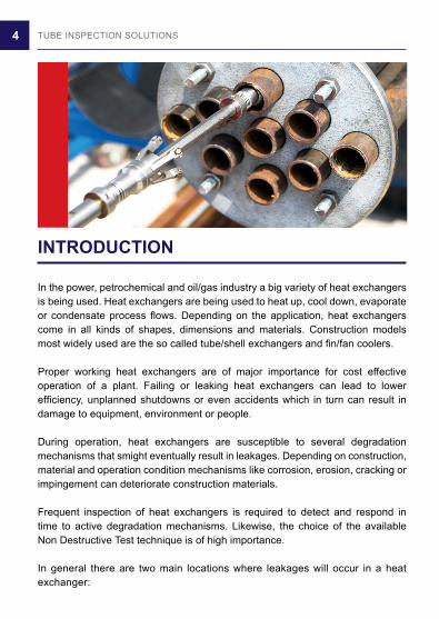
INTRODUCTION
In the power, petrochemical and oil/gas industry a big variety of heat exchangers is being used. Heat exchangers are being used to heat up, cool down, evaporate or condensate process flows. Depending on the application, heat exchangers come in all kinds of shapes, dimensions and materials. Construction models most widely used are the so called tube/shell exchangers and fin/fan coolers.
Proper working heat exchangers are of major importance for cost effective operation of a plant. Failing or leaking heat exchangers can lead to lower efficiency, unplanned shutdowns or even accidents which in turn can result in damage to equipment, environment or people.
During operation, heat exchangers are susceptible to several degradation mechanisms that smight eventually result in leakages. Depending on construction, material and operation condition mechanisms like corrosion, erosion, cracking or impingement can deteriorate construction materials.
Frequent inspection of heat exchangers is required to detect and respond in time to active degradation mechanisms. Likewise, the choice of the available Non Destructive Test technique is of high importance.
In general there are two main locations where leakages will occur in a heat exchanger:
5TUBE INSPECTION SOLUTIONS
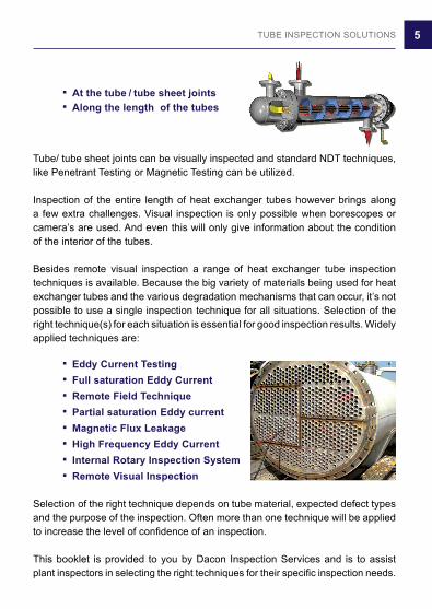
. At the tube / tube sheet joints . Along the length of the tubes
Tube/ tube sheet joints can be visually inspected and standard NDT techniques, like Penetrant Testing or Magnetic Testing can be utilized.
Inspection of the entire length of heat exchanger tubes however brings along a few extra challenges. Visual inspection is only possible when borescopes or camera’s are used. And even this will only give information about the condition of the interior of the tubes.
Besides remote visual inspection a range of heat exchanger tube inspection techniques is available. Because the big variety of materials being used for heat exchanger tubes and the various degradation mechanisms that can occur, it’s not possible to use a single inspection technique for all situations. Selection of the right technique(s) for each situation is essential for good inspection results. Widely applied techniques are:
. Eddy Current Testing . Full saturation Eddy Current . Remote Field Technique . Partial saturation Eddy current . Magnetic Flux Leakage . High Frequency Eddy Current . Internal Rotary Inspection System . Remote Visual Inspection
Selection of the right technique depends on tube material, expected defect types and the purpose of the inspection. Often more than one technique will be applied to increase the level of confidence of an inspection.
This booklet is provided to you by Dacon Inspection Services and is to assist plant inspectors in selecting the right techniques for their specific inspection needs.
6 TUBE INSPECTION SOLUTIONS
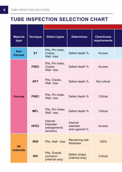
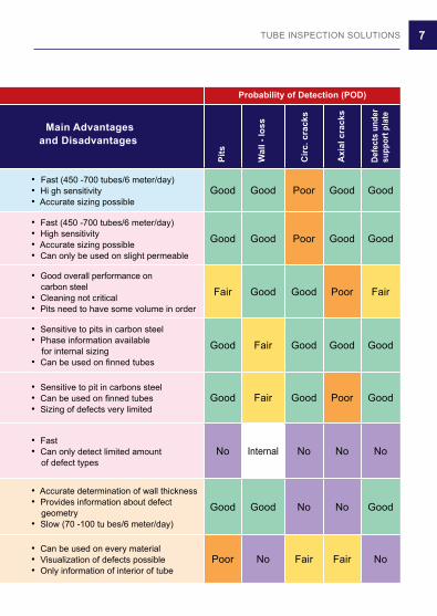
TUBE INSPECTION SELECTION CHART
Materialtype
Tecnique Defect types Determines Cleanlinessrequirements
Main Advantages and Disadvantages
NonFerrous ET
Pits, Pin holes,Cracks, Wall - loss
Defect depth % Access• Fast (450 -700 tubes/6 meter/day)• Hi gh sensitivity• Accurate sizing possible
Good Good Poor Good Good
Ferrous
FSECPits, Pin holes,Cracks, Wall - loss
Defect depth % Access• Fast (450 -700 tubes/6 meter/day)• High sensitivity• Accurate sizing possible• Can only be used on slight permeable
Good Good Poor Good Good
RFT Pits, Cracks,Wall - loss Defect depth % Not critical
• Good overall performance on carbon steel• Cleaning not critical• Pits need to have some volume in order
Fair Good Good Poor Fair
PSEC Pits, Pin holes,Wall - loss Defect depth % Critical
• Sensitive to pits in carbon steel• Phase information available for internal sizing• Can be used on finned tubes
Good Fair Good Good Good
MFL Pits, Pin Holes,Wall - loss Defect depth % Critical
• Sensitive to pit in carbons steel• Can be used on finned tubes• Sizing of defects very limited
Good Fair Good Poor Good
HFECInternalDiameterenlargements(erosion)
Internaldiameterenla rgement %
Access• Fast• Can only detect limited amount of defect types
No Internal No No No
Allmaterials
IRIS Pits, Wall - loss Remaining wallthickness 100%
• Accurate determination of wall thickness• Provides information about defect geometry• Slow (70 -100 tu bes/6 meter/day)
Good Good No No Good
RVIPits, Overallcorrosion(internal only)
Defect shape(internal only) Critical
• Can be used on every material• Visualization of defects possible• Only information of interior of tube
Poor No Fair Fair No
7TUBE INSPECTION SOLUTIONS
TUBE INSPECTION SELECTION CHART
Materialtype
Tecnique Defect types Determines Cleanlinessrequirements
Main Advantages and Disadvantages
NonFerrous ET
Pits, Pin holes,Cracks, Wall - loss
Defect depth % Access• Fast (450 -700 tubes/6 meter/day)• Hi gh sensitivity• Accurate sizing possible
Good Good Poor Good Good
Ferrous
FSECPits, Pin holes,Cracks, Wall - loss
Defect depth % Access• Fast (450 -700 tubes/6 meter/day)• High sensitivity• Accurate sizing possible• Can only be used on slight permeable
Good Good Poor Good Good
RFT Pits, Cracks,Wall - loss Defect depth % Not critical
• Good overall performance on carbon steel• Cleaning not critical• Pits need to have some volume in order
Fair Good Good Poor Fair
PSEC Pits, Pin holes,Wall - loss Defect depth % Critical
• Sensitive to pits in carbon steel• Phase information available for internal sizing• Can be used on finned tubes
Good Fair Good Good Good
MFL Pits, Pin Holes,Wall - loss Defect depth % Critical
• Sensitive to pit in carbons steel• Can be used on finned tubes• Sizing of defects very limited
Good Fair Good Poor Good
HFECInternalDiameterenlargements(erosion)
Internaldiameterenla rgement %
Access• Fast• Can only detect limited amount of defect types
No Internal No No No
Allmaterials
IRIS Pits, Wall - loss Remaining wallthickness 100%
• Accurate determination of wall thickness• Provides information about defect geometry• Slow (70 -100 tu bes/6 meter/day)
Good Good No No Good
RVIPits, Overallcorrosion(internal only)
Defect shape(internal only) Critical
• Can be used on every material• Visualization of defects possible• Only information of interior of tube
Poor No Fair Fair No
Probability of Detection (POD)
Pits
Wal
l - lo
ss
Circ
. cra
cks
Axi
al c
rack
s
Defe
cts
unde
rsu
ppor
t pla
te

8 TUBE INSPECTION SOLUTIONS
CONVENTIONAL EDDY CURRENT
Eddy Current is the notably the fastest and most preferred tube inspection technique available. Eddy Current however can only be used on non-ferrous materials like Brass, Copper, Copper-Nickel and Stainless steel.
Local defects as well as overall wall-loss can be detected and quantified. EC can detect both internal and external defects and can distinguish between them. Cracks can be detected depending on their size and orientation. By applying Multi frequencies, defects under support plates can be detected and to some extent quantified.
Theory The probe used in Eddy Current examination contains a coil which generates a changing magnetic field. When the probe is inside a tube of a conductive material this magnetic field will cause eddy currents to flow in the tube material. The amount of eddy currents that can flow in the tube depends on the condition of the tube at the location of the coils. The Eddy currents will in their turn generate a magnetic field which opposes the original magnetic field of the coil. The resultant of the two opposing magnetic fields influences the impedance of the coil in the probe. This means the impedance of the test coil depends on the condition of the tube. Signals that represent the impedance of the test coil and thus the condition of the tube are presented on a computer screen.

9TUBE INSPECTION SOLUTIONS
Advantages / possibilities Disadvantages / limitations
• Fast (450-700 tubes per day)• Overall wall-loss and local defects can bedetected• High sensitivity to small defects (diam. holes/pits > 0.5 mm)• Accurate sizing of defects possible• Possible to distinguish between in-and external defects• Possible to detect and quantify defects under support plates• Cracks can be detected depending on size and orientation• Only basic cleaning of tubes required
• Only on thin or slightly permeable materials• Gradual defects could be under classified
10 TUBE INSPECTION SOLUTIONS
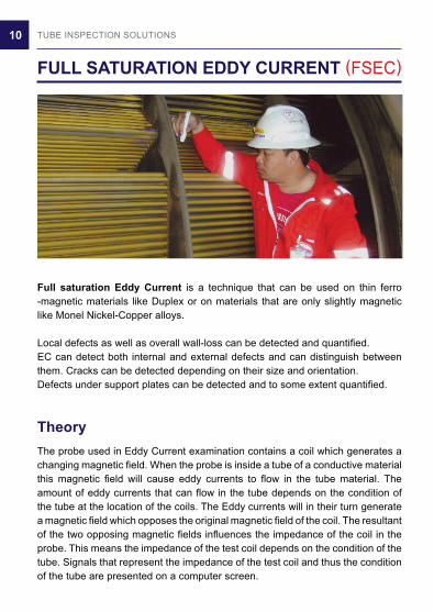
FULL SATURATION EDDY CURRENT (FSEC)
Full saturation Eddy Current is a technique that can be used on thin ferro -magnetic materials like Duplex or on materials that are only slightly magnetic like Monel Nickel-Copper alloys.
Local defects as well as overall wall-loss can be detected and quantified. EC can detect both internal and external defects and can distinguish between them. Cracks can be detected depending on their size and orientation. Defects under support plates can be detected and to some extent quantified.
Theory The probe used in Eddy Current examination contains a coil which generates a changing magnetic field. When the probe is inside a tube of a conductive material this magnetic field will cause eddy currents to flow in the tube material. The amount of eddy currents that can flow in the tube depends on the condition of the tube at the location of the coils. The Eddy currents will in their turn generate a magnetic field which opposes the original magnetic field of the coil. The resultant of the two opposing magnetic fields influences the impedance of the coil in the probe. This means the impedance of the test coil depends on the condition of the tube. Signals that represent the impedance of the test coil and thus the condition of the tube are presented on a computer screen.
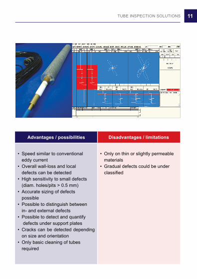
11TUBE INSPECTION SOLUTIONS
Advantages / possibilities Disadvantages / limitations
• Speed similar to conventional eddy current• Overall wall-loss and local defects can be detected• High sensitivity to small defects (diam. holes/pits > 0.5 mm)• Accurate sizing of defects possible• Possible to distinguish between in- and external defects• Possible to detect and quantify defects under support plates• Cracks can be detected depending on size and orientation• Only basic cleaning of tubes required
• Only on thin or slightly permeable materials• Gradual defects could be under classified
12 TUBE INSPECTION SOLUTIONS
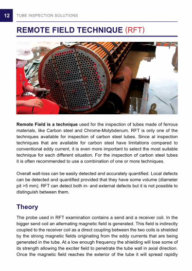
REMOTE FIELD TECHNIQUE (RFT)
Remote Field is a technique used for the inspection of tubes made of ferrous materials, like Carbon steel and Chrome-Molybdenum. RFT is only one of the techniques available for inspection of carbon steel tubes. Since al inspection techniques that are available for carbon steel have limitations compared to conventional eddy current, it is even more important to select the most suitable technique for each different situation. For the inspection of carbon steel tubes it is often recommended to use a combination of one or more techniques.
Overall wall-loss can be easily detected and accurately quantified. Local defects can be detected and quantified provided that they have some volume (diameter pit >5 mm). RFT can detect both in- and external defects but it is not possible to distinguish between them.
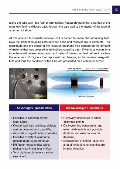
Theory The probe used in RFT examination contains a send and a receiver coil. In the bigger send coil an alternating magnetic field is generated. This field is indirectly coupled to the receiver coil as a direct coupling between the two coils is shielded by the strong magnetic fields originating from the eddy currents that are being generated in the tube. At a low enough frequency the shielding will lose some of its strength allowing the exciter field to penetrate the tube wall in axial direction. Once the magnetic field reaches the exterior of the tube it will spread rapidly
13TUBE INSPECTION SOLUTIONS
along the tube with little further attenuation. Research found that a portion of the magnetic field re-diffuses back through the pipe wall to the interior of the tube at a certain location.
At this position the smaller receiver coil is placed to detect the remaining field. Now the indirect coupling path between send and receiver coil is complete. The magnitude and the phase of the received magnetic field depend on the amount of material that was crossed in the indirect coupling path. If wall-loss occurs in a tube there will be less attenuation and delay of the exciter field before it reaches the receiver coil. Signals that represent the changing in the received magnetic field and thus the condition of the tube are presented on a computer screen.
Advantages / possibilities Disadvantages / limitations
• Possible to examine carbon steel tubes• Overall wall-loss and local defects can be detected and quantified.• Accurate sizing of defects possible• Possible to detect volumetric defects under support plates• Fill factor not so critical which makes cleanliness less critical.• Very big tube diameters can be examined
• Relatively insensitive to small diameter pitting• Distinguishing between in- and external defects is not possible (both in- and external can be detected).• Examination of finned tubes has a lot of limitations unless fins are in axial direction
14 TUBE INSPECTION SOLUTIONS
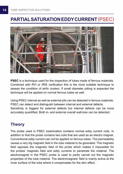
PARTIAL SATURATION EDDY CURRENT (PSEC)
PSEC is a technique used for the inspection of tubes made of ferrous materials. Combined with RVI or IRIS verification this is the most suitable technique to assess the condition of airfin coolers. If small diameter pitting is expected the technique will be applied on normal ferrous tubes as well.
Using PSEC internal as well as external pits can be detected in ferrous materials. PSEC can detect and distinguish between internal and external defects.Sensitivity is biggest for external defects but internal defects can be more accurately quantified. Both in- and external overall wall-loss can be detected.
Theory The probe used in PSEC examination contains normal eddy current coils. In addition to that the probe contains two coils that are used as an electro magnet. Conventional eddy current can not be applied on ferrous tubes. The permeability causes a very big magnetic field in the tube material to be generated. This magnetic field opposes the magnetic field of the probe which makes it impossible for the probes’ magnetic field and eddy currents to penetrate the material. The electromagnet in the PSEC probe is used to partly cancel out the magnetic properties of the tube material. The electromagnets’ field is mainly active at the inner surface of the tube where it compensates for the skin effect.
15TUBE INSPECTION SOLUTIONS
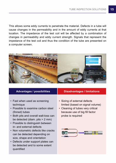
Advantages / possibilities Disadvantages / limitations
• Fast when used as screening technique• Possible to examine carbon steel (finned) tubes• Both pits and overall wall-loss can be detected (diam. pits > 2 mm)• Possible to distinguish between in- and external defects• Non volumetric defects like cracks can be detected depending on size, shape and orientation • Defects under support plates can be detected and to some extent quantified
• Sizing of external defects limited (based on signal volume)• Cleaning of tubes very critical because use of big fill factor probe is required
This allows some eddy currents to penetrate the material. Defects in a tube will cause changes in the permeability and in the amount of eddy currents at that location. The impedance of the test coil will be affected by a combination of changes in permeability and eddy current strength. Signals that represent the impedance of the test coil and thus the condition of the tube are presented on a computer screen.

16 TUBE INSPECTION SOLUTIONS
MAGNETIC FLUX LEAKAGE (MFL)
MFL is a technique used for the inspection of tubes made of ferrous materials. This technique will normally be applied as a fast screening technique if small diameter pitting is expected. Because of limitations to its sizing abilities the technique is not often used as a stand-alone technique. Verification by other techniques is recommended. MFL can also be used on airfin cooler tubes. MFL is sensitive to sharp type defects like pits and grooving. In- and external pits can be detected. Depending on probe configuration MFL can distinguish between in- and external defects and can detect gradual wall-loss. For ID/OD discrimination the probe needs to be equipped with a second coil and to detect gradual defects a Hall-effect sensor in the probe is needed.
Theory The probe in MFL contains permanent magnets which are utilized to form a magnetic flux field in the tube wall. Defects will influence the path of the magnetic field and will cause some of the flux to leak out of the tube wall. This leakage field will be picked up by the coils and the Hall-effect sensors in the probe. Size of the leakage field is determined by pull speed of the probe and by the shape, the dimensions and the location of defects. Signals that represent the size of the leakage field and thus the condition of the tube are presented on a computer screen.
17TUBE INSPECTION SOLUTIONS
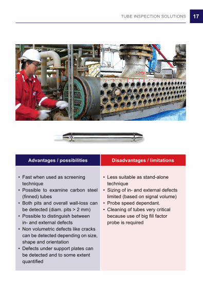
Advantages / possibilities Disadvantages / limitations
• Fast when used as screening technique• Possible to examine carbon steel (finned) tubes• Both pits and overall wall-loss can be detected (diam. pits > 2 mm)• Possible to distinguish between in- and external defects• Non volumetric defects like cracks can be detected depending on size, shape and orientation• Defects under support plates can be detected and to some extent quantified
• Less suitable as stand-alone technique• Sizing of in- and external defects limited (based on signal volume)• Probe speed dependant. • Cleaning of tubes very critical because use of big fill factor probe is required
18 TUBE INSPECTION SOLUTIONS
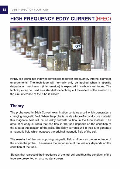
HIGH FREQUENCY EDDY CURRENT (HFEC)
HFEC is a technique that was developed to detect and quantify internal diameter enlargements. The technique will normally only be applied when a specific degradation mechanism (inlet erosion) is expected in carbon steel tubes. The technique can be used as a stand-alone technique if the extent of the erosion on the circumference of the tube is known.
Theory The probe used in Eddy Current examination contains a coil which generates a changing magnetic field. When the probe is inside a tube of a conductive material this magnetic field will cause eddy currents to flow in the tube material. The amount of eddy currents that can flow in the tube depends on the condition of the tube at the location of the coils. The Eddy currents will in their turn generate a magnetic field which opposes the original magnetic field of the coil.
The resultant of the two opposing magnetic fields influences the impedance of the coil in the probe. This means the impedance of the test coil depends on the condition of the tube.
Signals that represent the impedance of the test coil and thus the condition of the tube are presented on a computer screen.
19TUBE INSPECTION SOLUTIONS
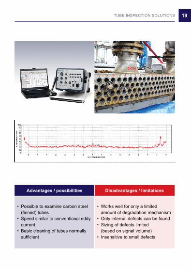
Advantages / possibilities Disadvantages / limitations
• Possible to examine carbon steel (finned) tubes• Speed similar to conventional eddy current• Basic cleaning of tubes normally sufficient
• Works well for only a limited amount of degradation mechanism• Only internal defects can be found• Sizing of defects limited (based on signal volume)• Insensitive to small defects

20 TUBE INSPECTION SOLUTIONS
IRIS
IRIS is a technique that can be applied on both ferrous and non-ferrous materials and even on non-conductive materials like plastics.
With IRIS the remaining wall thickness of tubes can be accurately measured. IRIS is more accurate than other tube inspection techniques and has the advantage of presenting information about the geometry of defects. Local defects and wall-loss on both sides of the tube can be accurately measured. Defects under support plates can be measured without any limitations.
Theory The probe used in IRIS examination is made up of a centering device, an ultrasound transducer and a rotating mirror. An ultrasound pulse will be generated in the transducer that is mounted in axial direction. A 45 degree rotating mirror in the probe will guide the sound bundle towards the tube wall. An ultrasound reflection (echo) will take place at the inner and at the outer wall of the tube. These echoes are reflected back and processed by the equipment. The time between these two echoes represents the wall thickness of the tube. Knowing the sound velocity in the material under test, an accompanying wall thickness can be calculated. Water is used rotate the probe mirror and is also needed as a couplant between the transducer and the tube wall.
21TUBE INSPECTION SOLUTIONS
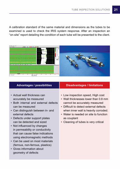
Advantages / possibilities Disadvantages / limitations
• Actual wall thickness can accurately be measured• Both internal and external defects can be measured• Can distinguish between in- and external defects• Defects under support plates can be detected and sized• Not influenced by changes in permeability or conductivity that can cause false indications using electromagnetic methods• Can be used on most materials (ferrous, non-ferrous, plastics)• Gives information about geometry of defects
• Low inspection speed, High cost• Wall thicknesses lower than 0.8 mm cannot be accurately measured• Difficult to detect external defects when inner wall is heavily corroded.• Water is needed on site to function as couplant• Cleaning of tubes is very critical
A calibration standard of the same material and dimensions as the tubes to be examined is used to check the IRIS system response. After an inspection an “on-site” report detailing the condition of each tube will be presented to the client.

22 TUBE INSPECTION SOLUTIONS
REMOTE VISUAL INSPECTION (RVI)
RVI can be used to visually inspect every possible tube. RVI doesn’t provide any information about defect depth. But it can be useful to obtain information about defect geometry and the possibly present degradation mechanisms in a tube. Defects can be photographed and the image of the whole tube can be video taped. RVI is mainly used as a back up tool to verify the results of the other techniques.
Advantages / possibilities Disadvantages / limitations
• Can be used on every material• Gives information about geometry of defects• Visualization of defects gives high level of conifidence
• Sizing of defects not possible• Only the internal tube wall can be examined• High level of cleanliness required
23TUBE INSPECTION SOLUTIONS
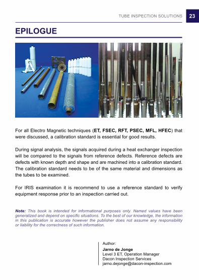
EPILOGUE
For all Electro Magnetic techniques (ET, FSEC, RFT, PSEC, MFL, HFEC) that were discussed, a calibration standard is essential for good results.
During signal analysis, the signals acquired during a heat exchanger inspection will be compared to the signals from reference defects. Reference defects are defects with known depth and shape and are machined into a calibration standard. The calibration standard needs to be of the same material and dimensions as the tubes to be examined.
For IRIS examination it is recommend to use a reference standard to verify equipment response prior to an inspection carried out.
Note: This book is intended for informational purposes only. Named values have been generalized and depend on specific situations. To the best of our knowledge, the information in this publication is accurate however the publisher does not assume any responsibility or liability for the correctness of such information.
Author:Jarno de JongeLevel 3 ET, Operation ManagerDacon Inspection [email protected]

24 TUBE INSPECTION SOLUTIONS
NOTES

25TUBE INSPECTION SOLUTIONS
NOTES

26 TUBE INSPECTION SOLUTIONS
NOTES

27TUBE INSPECTION SOLUTIONS
NOTES

28 TUBE INSPECTION SOLUTIONS
DACON INSPECTION SERVICES CO.,LTD.78/4 Moo 6, Sukhumvit Road, Ban Chang Rayong, 21130, THAILANDPhone: +66 38 880788 Fax: +66 38 880727Email: [email protected]
www. dacon-inspection.com


![Remote Inspection of Welded Joints [Disc 5]moltensalt.org/references/static/downloads/pdf/ORNL-TM-3561.pdf · REMOTE INSPECTION OF WELDED JOINTS R. W. McClung ABSTRACT Maintenance](https://static.fdocuments.in/doc/165x107/5e6a577bee913d52cd4e62fd/remote-inspection-of-welded-joints-disc-5-remote-inspection-of-welded-joints-r.jpg)