Tube Heater General Manual - Wholesale Distributors · Tube Heater Installation, Operation,...
28
Tube Heater Installation, Operation, Maintenance and Parts Manual WARNING: This heater must be installed and serviced by trained gas installation and service personnel only! Improper installation, adjustment, alteration, service or maintenance can cause property damage, injury or death. Read the installation, operating and maintenance instructions thoroughly before installing or servicing this equipment. Protect yourself and others by observing all safety information. Retain instructions for future reference. Description Tube heaters are gas-fired infrared heaters designed to provide comfort heat. They consist of three (3) main components: a burner control box, radiant tube, and reflector assembly. The heaters are typically suspended from the ceiling by chains and controlled by a thermostat. They can be installed either vented or unvented, and may use outside air for combustion if necessary. The radiant tube may be installed in different configurations depending on the heating requirements. These heaters use infrared energy to heat spaces. When heat is required, the burner control box ignites a gas/air mixture and pushes the hot gases into the radiant tube. As the gases pass through the assembly, the tubing is heated and emits infrared, which is then directed toward the floor by reflectors. This is known as primary infrared and is absorbed by the floor, objects and people in the space, raising their temperatures. They in turn reradiate this heat, known as secondary infrared, to create a comfort zone at the floor level. This is how tube heaters can heat large spaces without having to provide primary infrared for every square foot of area. However, if the goal is to spot heat a small area within a large space, only the primary infrared makes this possible. Tube heaters are design certified for use in industrial and commercial buildings, such as warehouses, manufacturing plants, aircraft hangars and vehicle maintenance shops. No heater may be used in a class 1 or class 2 explosive environment. Unless otherwise indicated, they are not certified for residential use or where flammable gases or vapors are generally present, such as spray booths. Printed in U.S.A. ©Detroit Radiant Products Co. 2003 Form# LIOGT-0M-02/04 (ID) (Replaces LIOGT-10M-05/03) Tube Heater General Manual FOR YOUR SAFETY Do not store or use gasoline or other flammable vapors and liquids in the vicinity of this or any other appliances. FOR YOUR SAFETY What to do if you smell gas: • Do not try to light any appliance. • Do not touch any electrical switch; do not use any phone in your building. • Immediately call your gas supplier from a neighbor’s phone. Follow the gas supplier’s instructions. • If you cannot reach your gas supplier, call the fire department. ! CONSIGNES DE SÉCURITÉ Sivous sentez une odeur de gaz: 1. Ouvrez les fenêtres. 2. Ne touchez pas aux interrupteurs électriques. 3. Eteingnez toute flamme nue. 4. Contactez immédiatement votre compagnie de gaz. Il est interdit d’utiliser des liquides inflammables ou dégageant des vapeurs inflammables, á proximité de tout appareil fonctionnant au gaz. ′ WARNING! In locations used for the storage of combustible materials, signs must be posted to specify the maximum permissible stacking height to maintain the required clearances from the heater to the combustibles. Signs must either be posted adjacent to the heater thermostats or in the absence of such thermostats in a conspicuous location. !
Transcript of Tube Heater General Manual - Wholesale Distributors · Tube Heater Installation, Operation,...

Tube Heater Installation, Operation, Maintenance and Parts Manual
WARNING: This heater must be installed and serviced by trained gas installation and service personnel only!Improper installation, adjustment, alteration, service or maintenance can cause property damage, injury or death.Read the installation, operating and maintenance instructions thoroughly before installing or servicing this equipment.Protect yourself and others by observing all safety information. Retain instructions for future reference.
Description
Tube heaters are gas-fired infrared heaters designedto provide comfort heat. They consist of three (3)main components: a burner control box, radiant tube,and reflector assembly. The heaters are typicallysuspended from the ceiling by chains and controlledby a thermostat. They can be installed either ventedor unvented, and may use outside air for combustionif necessary. The radiant tube may be installed indifferent configurations depending on the heatingrequirements.
These heaters use infrared energy to heat spaces.When heat is required, the burner control box ignitesa gas/air mixture and pushes the hot gases into theradiant tube. As the gases pass through theassembly, the tubing is heated and emits infrared,which is then directed toward the floor by reflectors.This is known as primary infrared and is absorbedby the floor, objects and people in the space, raisingtheir temperatures. They in turn reradiate this heat,known as secondary infrared, to create a comfort zoneat the floor level. This is how tube heaters can heatlarge spaces without having to provide primaryinfrared for every square foot of area. However, ifthe goal is to spot heat a small area within a largespace, only the primary infrared makes this possible.Tube heaters are design certified for use in industrialand commercial buildings, such as warehouses,manufacturing plants, aircraft hangars and vehiclemaintenance shops. No heater may be used in aclass 1 or class 2 explosive environment. Unlessotherwise indicated, they are not certified forresidential use or where flammable gases or vaporsare generally present, such as spray booths.
Printed in U.S.A.©Detroit Radiant Products Co. 2003
Form# LIOGT-0M-02/04 (ID)(Replaces LIOGT-10M-05/03)
Tube HeaterGeneral Manual
FOR YOUR SAFETYDo not store or use gasoline or other flammablevapors and liquids in the vicinity of this or any otherappliances.
FOR YOUR SAFETYWhat to do if you smell gas:
• Do not try to light any appliance.• Do not touch any electrical switch; do not
use any phone in your building.• Immediately call your gas supplier from
a neighbor’s phone. Follow the gassupplier’s instructions.
• If you cannot reach your gas supplier,call the fire department.
!
CONSIGNES DE SÉCURITÉ
Sivous sentez une odeur de gaz:
1. Ouvrez les fenêtres.2. Ne touchez pas aux interrupteurs électriques.3. Eteingnez toute flamme nue.4. Contactez immédiatement votre compagnie de gaz.
Il est interdit d’utiliser des liquides inflammables oudégageant des vapeurs inflammables, á proximité
de tout appareil fonctionnant au gaz.
′′′′′
WARNING!In locations used for the storage of combustible materials,signs must be posted to specify the maximum permissiblestacking height to maintain the required clearances fromthe heater to the combustibles. Signs must either beposted adjacent to the heater thermostats or in theabsence of such thermostats in a conspicuous location.
!

Tube Heater Installation, Operation, Maintenance and Parts Manual
Tube Heaters
WARNING!
This is not an explosion-proof heater. Where thereis the possibility of exposure to flammable vapors,consult the local fire marshal, the fire insurancecarrier and other authorities for approval of theproposed installation.
WARNING!
NOT FOR RESIDENTIAL USE!(Unless otherwise noted)
Do not use in the home, sleepingquarters, attached garages, etc.
2
See product insert for specificcautions, warnings, electrical and
other model specific data.
WARNING!
Do not operate heater with any partbypassed, with any part failed or in anyscenario that may compromise safety.
WARNINGS
Maintain all Clearance to Combustibles at all times. See page 5 for Clearance to Combustiblesguidelines. See page 2 of manual insert for specific clearance to combustibles data.
This infrared heater is designed for use in industrial and commercial buildings such as warehouses,manufacturing plants, aircraft hangars, service garages, etc.
Detroit Radiant Products Company cannot anticipate every use which may be made of their heaters.Check with your local fire safety authority if you have questions about local regulations.
This heater must be installed and serviced bytrained gas installation and service personnel only.Read and understand these instructions thoroughlybefore attempting to install, operate or service thisheater. Failure to comply could result in personalinjury, asphyxiation, death, fire, and/or propertydamage. Retain these instructions for futurereference.
WARNING!! !
!
!

3
Tube Heater Installation, Operation, Maintenance and Parts Manual
Table of Contents and Certifications
1. SAFETY INFORMATION 4
2. INSTALLATION2.1 Design Criteria 62.2 Location and Coverage 72.3 Installation Considerations 72.4 Prechecks 92.5 Heater Mounting 112.6 Baffle Assembly 142.7 Reflector Accessories and Assembly 152.8 Optional “L” or “U” Configuration 172.9 Flue Venting 192.10 Installation for Unvented Operation (Optional) 212.11 Combustion Air Requirements 222.12 Gas Supply 23
3. OPERATION3.1 Electrical Requirements 253.2 Lighting Instructions 253.3 Shutdown Instructions 25
4. MAINTENANCE 264.1 Troubleshooting Chart 27
5. LIMITED WARRANTY 28
Approval Standards and CertificationsDetroit Radiant Products Units comply with or are certified by one or more of the following organizations or standards:
!!!!! CSA International (CSA)!!!!! American National Standards (ANSI Z83.6, Z83.20, Z83.20a)!!!!! Occupational Safety and Health Act (OSHA)!!!!! American Gas Association (AGA/CSA)!!!!! International Approval Services (IAS)!!!!! Canadian Gas Association (CGA/CSA)!!!!! National Standards of Canada!!!!! Certification of Europe (CE)!!!!! A.G.A. Requirements for Residential Radiant Tube Heaters 7-89.!!!!! See page 12 of manual insert for specific product
certifications and approvals.
IMPORTANT!
Any alteration of the system or of the factory-authorized components specified in this manualor by Detroit Radiant Products Company voids all certification and warranties.

4
Tube Heater Installation, Operation, Maintenance and Parts Manual
Check the CSA rating label on theheater to verify the proper gas to
be used. Check the other labels on the heater toverify proper mounting and clearance tocombustibles.
The installation of this heater must conform with localbuilding codes or, in the absence of local codes,with the National Fuel Gas Code, ANSI Z223.1(NFPA 54) (latest edition). Applications in Canadamust conform to CAN/CGA B149.1 and 2 codes andCanadian Electrical Code C22.1 (latest edition).
Under no circumstance is either the gas supply lineor the electrical supply line to the heater to provideany assistance in the suspension of the heater.
The weight of the heater must be entirely suspendedfrom a permanent part of the building structure havingadequate load characteristics.
Neither the gas supply line, electrical supply line norsprinkler heads shall be located within the minimumclearance to combustibles as shown in theClearance-to-Combustibles Chart on page 2 ofmanual insert.
! CAUTION
1. SAFETYINFORMATION
Signs must be posted in storage areas to specifymaximum stacking height allowed in order to maintainclearance to combustibles. DRP part #PLQ warningplaques are recommended.
GARAGES
The installation of this heater in public garages mustconform with the Standard for Parking Structures,ANSI/NFPA 88A (latest edition), or the Standard forRepair Garages, ANSI/NFPA 88B (latest edition),and must be at least 8 ft. above the floor (see page 5for Clearance to Combustibles). Applications inCanada must conform to the Canadian Electric CodeC22.1 (latest edition) when an external electricalsource is used.
HANGARS
The installation of this heater in aircraft hangars mustconform with the Standard for Aircraft Hangars, ANSI/NFPA 409 (latest edition). The heater must beinstalled at least 10 ft. above the upper wing surfacesand engine enclosures of the highest aircraft whichmight be stored in the hangar. In areas adjoining theaircraft storage area, the heaters must be installedat least 8 ft. above the floor. The heaters must belocated in areas where they will not be subject todamage by aircraft, cranes, movable scaffolding orother objects.
ELECTRICAL
The heater, when installed, must be electricallygrounded in accordance with the National ElectricalCode ANSI/NFPA 70 (latest edition).
The following must be reviewed before installing this heater.
Detroit Radiant Products Company21400 Hoover Road ♦ Warren, MI 48089 ♦ (586) 756-0950 ♦ Fax: (586) 756-2626
E-mail: [email protected]: www.reverberray.com
Tube Heaters
IMPORTANT NOTE
Unless otherwise indicated on the CSA RatingLabel (Chart 2 (C2) or Chart 3 (C3)), this infra-red heater is designed to operate on standardBTU gas (either 1000 BTU ft3 for natural gas or2500 BTU ft3 for propane gas) at elevations 0 to4000 feet MSL (Sea Level).

Clearances to combustibles zone
BELOW90º + Ambient
TOP90º + Ambient
SID
E90
º + A
mbi
ent
SID
E90
º + A
mbi
ent
5
Tube Heater Installation, Operation, Maintenance and Parts Manual
For the safe installation of this unit, consult theclearance to combustibles chart on page 2 of theproduct manual insert. It contains clearances thatmust be maintained.
Failure to comply with thestated clearance to
combustibles could result in personal injury,death and/or property damage.
! WARNING ! WARNING This heater should beinstalled so that the minimum
clearance to combustibles, as marked on theheater, will be maintained from vehicles parkedbelow. If vehicle lifts are present, ensure thatthese clearances will be maintained from thehighest raised vehicle.
Determination of publishedclearance to combustibles.
Clearance to combustible distances are determined to bethe point (usually measured in inches) at which a blacksurface is raised 90 degrees hotter than the roomtemperature.
Step 1:
Step 2:
Step 3:
Step 4:
NOTE: Infra-red heaters can cause discomfort to buildingoccupants if the heaters are mounted too low. Therefore,a minimum mounting height is recommended, based uponthe clearance to combustibles and the specified minimummounting height. Also, a maximum mounting height foreach heater is recommended for effective radiant heating.
Highly absorbent black walls are placed aroundthe heater’s exchanger at the hottest point.
These walls are moved inward or outward untilthe standard temperature of 90ºF plus ambient(room temperature) is achieved. (ANSI Z83.20)
Once this temperature is achieved, the distancefrom the heater to these walls are then measuredand recorded as the minimum clearance tocombustibles.
This process is repeated at a distance 20 feetdownstream from the heater to gather reducedclearance to combustibles data.
Safety InformationClearances to Combustibles
Distance
DistanceDistance
Distance

Tube Heater Installation, Operation, Maintenance and Parts Manual
NOTE: Must also note BTU chart (top right) for minimum mounting heights.
Tube Heaters
6
NOTE: These charts are provided as guidelines. Actual conditions may dictate variation from this data.
Chart 2: Straight Tubes
Chart 3: Spot “U” Tubes
MODEL OVERALL TYP. MTG.FT. DIM. HEIGHTS LOW BTU & MOUNT MID BTU & MOUNT HIGH BTU & MOUNT
10' Straight 12'-3" 8' Min. 10' x 10' N / A N / A20' Straight 22'-0" 9' - 20' 20' x 12' 22' x 15' N / A30' Straight 31'-3" 10' - 25' 30' x 14' 33' x 18' N / A40' Straight 40'-11" 11' - 30' 40' x 16' 44' x 21' 45' x 26'50' Straight 50'-7" 15' - 40' N / A 55' x 24' 56' x 30'60' Straight 60'-3" 16' - 40' N / A 66' x 27' 67' x 34'70' Straight 69'-11" 19' - 42' N / A N / A 78' x 38'80' Straight 79'-7" 20' - 45' N / A N / A 89' x 42'
APPROXIMATE DIRECT COVERAGE AREA (LENGTH X WIDTH)
MODEL OVERALL TYP. MTG.FT. DIM. HEIGHTS LOW BTU & MOUNT MID BTU & MOUNT HIGH BTU & MOUNT
20 "U" 13'-0" 10' - 15' 12' x 12' N / A N / A*30 "U" 17'-10' 10' - 20' 17' x 13' 18' x 15' N / A40 "U" 22'-8" 10' - 25' 22' x 14' 23' x 17' 24' x 20'*50 "U" 27'-6" 13' - 30' N / A 28' x 19' 29' x 23'60 "U" 32'-4" 15' - 35' N / A 33' x 21' 34' x 26'*70 "U" 37'-2" 16' - 35' N / A N / A 39' x 29'80 "U" 42'-0" 16' - 35' N / A N / A 44' x 32'
APPROXIMATE DIRECT COVERAGE AREA (LENGTH X WIDTH)
2. INSTALLATION
2.1 Design CriteriaDesigning an infra-red heating system is often a balance betweenmeeting the required heat load and providing proper and adequatecoverage (similar to lighting). The charts on this page are intendedto be used after a total building heat load has been calculated. It ishighly recommended that you consult a professional to ensure aproperly designed heating system.
The charts are provided as guidelines for designing an infra-redsystem only. Chart 1 provides the minimium factory recommendedmounting height. The “Type” classification refers to the BTU outputmounting height catagory. Chart 2 provides guidelines for designinga total building heat system, most often accomplished using straighttube heaters. Chart 3 provides guidelines for designing a spot buildingheat system, most often accomplished using ‘U’ configured tubeheaters. See the following page for other guideline considerations.
Design Criteria
BTU's Height Type25,000 8' Low40,000 9' Low50,000 10' Low60,000 11' Low75,000 12' Mid100,000 13' Mid*125,000 15' Mid*150,000 16' High175,000 17' High200,000 18' High225,000 19' High
Recommended Minimum Mounting Heights
Chart 1: BTU Mtg. Hts. & Type
*30’ 100 & 125 models may also beconsidered as high output heaters.
*Models require 5EA-Sub.

40' - 100,000 BTU (typ. 4)
NOTE: DOORS &TRACKS NOTE:
EQUIPMENT STORAGE
NOTE: DOORS &TRACKS
GAS SUPPLYSidewall Vent (typ. 2)
BETTER HEAT DISTRIBUTION
7
Tube Heater Installation, Operation, Maintenance and Parts Manual
Installation
2.3 Considerations
• TheoryIs the building’s heat loss properly sized and met?Can a perimeter mount application be achieved?Are the highest heat load areas (doors, loadingdocks, etc.) covered with extra heat?
• Clearance to CombustiblesObserve your models clearance to combustiblesat all times. Look for door tracks, car lifts, storageareas, cranes, contaminated spaces, future storageareas, etc. Are there sprinkler heads too close tothe heaters? Place warning plaques whereneeded.
• HeightsIs the mounting height of the heater applicable toits’ BTU as shown in Chart 1?
• DistributionRemember that, by design, a straight infra-redheater will produce more heat at the supply(burner) end than at the exhaust end. Is the burnerend placed where more heat is desired?
• ReflectorsIs there a need to offset the heaters and rotate thereflectors towards the heat zone? Most heatersallow the reflectors to rotate from 0-45 degrees,although 0-30 degrees is factory recommended.Are extra accessories such as guards, side shields,U or L hoods needed?
• EnvironmentIs your environment harsh or contaminated?Have you chosen the right model for yourapplication? Does your application require usingoutside air, as most do? Is evaporation of oilsand chemicals a concern?
2.2 Location and Coverage
The placement of infra-red heaters is influenced by many factors. These includethe design theory, clearances to combustibles, mounting heights, distribution,reflectors, environment and equipment selection. A trained representative orother professional should be contacted to assist in designing a proper system.
The figures shown below are of a sample building 90’(L) x 50’(W) x 14’(H) requiring400,000 BTU’s, both heated with 160’ of radiant pipe. Figure 2-1 is an example ofa poorly designed system. This figure places two burners on one end, the endopposite the highest demand, violates the minimum mounting height and willproduce uneven heating. Figure 2-2 utilizes 4 burners, one placed in each cornerof the building. This is a far better design than illustrated in figure 2-1.
TOOHOT
NOTE: DOORS &TRACKS
TOOCOLD
NOTE: EQUIPMENT
STORAGE
NOTE: DOORS &TRACKS
GAS SUPPLY
80' - 200,000 BTU (Typ. 2)
Figure 2-1: Sample Layout (Incorrect).
Figure 2-2: Sample Layout (Correct).
TOOCOLD
TOOHOT
Better HeatDistribution

Tube Heaters
8
Tube Heater Installation, Operation, Maintenance and Parts Manual
When positioning heaters, keep in mind the clearanceto combustible materials, lights, sprinkler heads,overhead doors, storage areas with stackedmaterials, gas and electrical lines, parked vehicles,cranes and any other possible obstructions orhazards. Refer to the Warnings, Cautions and theClearance to Combustibles chart in the SafetyInformation Section and on the heater to verify that asafe installation condition exists.
Consult Detroit Radiant Products if you have aspecial case requiring a lower mounting height.
The following guidelines must also be met to ensurea good installation and proper heater performance:
• A maximum of two 90° elbows or one 180° elbowcan be installed on heaters. The gas input of theheaters, as stated on the rating label, willdetermine the minimum length of radiant pipe fromthe control box to the first elbow. (See optional90° and 180° elbows section.)
- IMPORTANT -
• Do not exceed the maximum vent length forexhausting the heater. Consult section 2.9 forguidelines.
NOTE: Flue vent requirements do not change whenelbows are installed.
Do not combine the exhaust vents of two heatersinto a straight through tee. A ‘Y’ assembly or astaggered tee arrangement must be used. A 6-inchdiameter (4-inch for LS and LD models) vent mustbe used when common venting (see figures 2-26 &27). Common vented units must also be controlledby the same control/thermostat.
Outside air for combustion must be ducted to theheater if the building atmosphere where the heateris installed contains one of the following:
• Chemicals such as chlorinated or fluorinatedhydrocarbons.
• High humidity such as car washes.
• Contaminants such as sawdust, welding smoke,etc.
• Negative static pressure.
Consult Combustion Air Requirements section onpage 22.
• Do not exceed the maximum duct length for freshair intake. Consult Air Intake Duct Chart on page22.
• Do not draw fresh air into the heater from an atticspace. There is no guarantee that adequate airwill be supplied.
• All unvented heaters must use Part No. WVE-GALV vent with flapper.
Once all of the safety precautions and design criteriaare met, the actual installation of the heater maybegin.

9
Tube Heater Installation, Operation, Maintenance and Parts Manual
2.4 Prechecks
1. Verify that all parts have been received bychecking them against the packing list. If anythingis missing, notify the product representative orDetroit Radiant Products Company.
2. Check the CSA rating label on the heater to verifythe model number, the gas to be used and verifythat the clearance to combustibles will be met.
3. Make sure the finished installation will conform tothe design requirements listed in the Clearanceto Combustibles Chart on page 2 of the manualinsert.
Installation
TYPICAL INSTALLATION DRAWING Fig 2-3
3 IN. DIA. VENT PIPE(LS/LD only)4 IN. DIA. VENT PIPE (4” Models)

29"
5"
8.125"
16"
18"
"C" "C"
5.5"
3.5" 3"
Tube Heaters
10
Tube Heater Installation, Operation, Maintenance and Parts Manual
Chart 4
"B" "B""B"
"A"
"C"
"B""C"
16" 12"
MODELDIMENSION A
(Straight configuration*)
SUSPENSION PONTS B
CONTROL BOX STABILIZER C
SHIPPING WEIGHT
S.S. WEIGHT
CHAIN SET QTY.
"Straight"
CHAIN SET QTY. W/TF1B
10 Foot 12'-3" / 147" 2 2 85# N/A 4 N/A20 Foot 22'-0" / 264" 3 2 120# 145# 5 630 Foot 31'-3" / 375" 4 2 160# 195# 6 740 Foot 40'-11" / 491" 5 2 190# 235# 7 850 Foot 50'-7" / 607" 6 2 235# 290# 8 960 Foot 60'-3" / 723" 7 2 265# 330# 9 1070 Foot 69'-11" / 839" 8 2 300# 375# 10 1180 Foot 79'-7" / 955" 9 2 330# 405# 11 12
* See page 18 for U-tube configurations.

11
Tube Heater Installation, Operation, Maintenance and Parts Manual
2.5 Heater Mounting
Mount heaters in conformance with approvalstandards referenced in the foreword.
1. Each unit is equipped with the necessaryhangers for installation. If spacing does notallow for standard mounting, additional hangers(TP-19B) may be necessary. See figure 2-8 onpage 13.
Fig. 2-4
2. Use of number 1 double loop chain isrecommended for heater hanging (AccessoryTHCS). See figure 2-5.
3. Lay out all tubing in proper position. 10’combustion chamber first, aluminized chambersecond (150-200MBH models only) and radiant tubesthereafter.
4. Two hangers support the first tube; one hangerper tube thereafter. The radiant tubes should bein straight alignment and level to the ground. Seefigure 2-8.
5. Mount hangers. Spacing between burner boxmounting brackets and the first hanger should beapproximately 2ft. - 4in. (figure 2-8). Spacingbetween the first two hangers should beapproximately 8ft. -10in. so as to support the firsttube. Spacing for every hanger thereafter shouldbe approximately 9ft. - 8in.
6. Mount the burner in straight alignment with tubes.Burner sight glass should be visible from the floor.
7. Install heater so that it is independently supportedand does not rely on the gas or electrical lines forsupport.
8. Installation of baffles. Baffle(s) should beassembled and then placed in the tube(s) farthestdownstream from the burner. In some cases thebaffles may have to be slid partially into thesecond from last tube. All baffles must be in thevertical position. See figure 2-10 and instructionson page 14 for assembly.
9. On all models except LS or LD Series, remove3 ft. baffle section (Part No. TP65I) if utilizing a‘U’ or ‘L’ shaped accessory fitting.
Installation
Fig. 2-5

12
Tube Heater Installation, Operation, Maintenance and Parts Manual
INSTALLATION NOTES:
IMPORTANT: Mount burner control box level to theground. Do not rotate control box assembly.
IMPORTANT: Baffles must be installed in the last(furthest from the burner) radiant tubes. See figure2-10 and details on page 14. All baffles must be inthe vertical position.
IMPORTANT: 175,000 through 225,000 BTU/Hmodels must be installed with a stainless steel tubeclamp at the second joint of the exchanger betweenthe combustion tube and second radiant tube.
IMPORTANT: 150-200 MBTU/H* models must beinstalled with the 10 foot, titanium alloy aluminizedtube directly following the burner box with thealuminized tube immediately following. Theidentification sticker found on the swaged end ofthe tubing will identify the titanium combustion tube.* All LS and LD Models are installed with the 10foot titanium alloy aluminized steel tube as the firsttube section. Do not use the aluminized steeltubing as the first tube section (combustionchamber).
IMPORTANT: Mount all tubes with welded seamfacing downward (See fig. 2-7). Be sure to haveswaged ends pointed towards the exhaust end of theheater.
NOTE: If windy conditions exist in the space aroundthe heater, it may be necessary to rigidly mount theheater to prevent swaying. It is recommended thatthreaded rod be used for the two hanging points atthe burner control box (see figure 2-6). The remaininghanging points should use chains to allow for heaterexpansion.
NOTE: The tube clamps provided with the heaterare pre-assembled at the factory. If a clamp isdismantled, it is important that upon re-assemblythe spacer is properly inserted (see figure 2-9). Thespacer’s concave surface must face the radiant tube.Incorrect spacer placement will result in shearing ofthe bolt when torqued to the recommendedspecifications (40-60-lb. ft.).
NOTE: Assemble the reflector after every 10-ft.section of emitter pipe installed.
NOTE: If tube clamp bolts are installed at the topside of the tube, make sure it does not interfere withthe expansion and contraction of the reflector nearthe reflector end cap.
Tube Heaters
Fig. 2-6
MOUNT BURNER BOX LEVEL
Fig. 2-7

13
Tube Heater Installation, Operation, Maintenance and Parts Manual
Installation
Fig. 2-8
Fig. 2-9
Fig. 2-10
(typical)
LAST TUBE
BAFFLE
BURNER CONTROL BOX
FIRST RADIANT TUBE OR COMBUSTION CHAMBER ALUMINIZED (50,000-125,000 BTU) or TITANIUM (150,000-225,000BTU)
RADIANT SENSOR BOX
TUBE CLAMP(STAINLESS STEEL ON 175, 200 & 225 MBH MODELS)
*LS And LD models utilize a titanium aluminized steel tube as the first radiant tube section (combustion chamber).^150-200MBTU/H models incorporate an aluminized steel radiant tube immediately following the first 10’ radiant tube/combustion chamber.
*^
Radiant sensor box
Burner control box
Tube clamp(Stainless steel on 175,000 & 200,000 models)
Baffle
Last tube
Tube ClampSwaged Tube
Seam
ClampCORRECT INCORRECT
FlatSurface
ConcavedSurface
Combustion Tube
Note: The first tube is supportedby two hangers with a spacingof apporximately 8’-10”.
Note: Spacing for every hangerafter the first two, isapproximately 9’-8”.
MountingChains
Reflector centersupport (RCS)(typical)
Reflector centersupport (RCS)
Seam Seam
Hanger Hanger Hanger8’ -10” 9’ - 8” Typical 9’ - 8” Typical
Hanger
Seam
2’ - 4”
First radiant tube/combustion chamber * ̂aluminized (50,000-125,000) or titanium (150,000-225,000 BTU/H)

Tube HeatersTube Heater Installation, Operation, Maintenance and Parts Manual
14
INSTALLER:
Avoid equipment failure!
The attached 3 ft. baffle section must beassembled with other enclosed baffles andplaced in the last tube(s) – (furthest fromburner). Remove one 3 ft. section if heateris installed with elbow or u-bend accessoryfittings on all models except on LS and LDmodels. Do not remove baffles on LS andLD Series heaters regardless of unitconfiguration. Refer to product specific insertfor further installation details.
2.6 Baffle Assembly Instructions
1. Remove enclosed baffles from the burner box andkeep with the applicable burner. Different burnersutilize different size baffles. Reference theshipping label for proper baffle size.
2. As shown below, assemble the baffle to the properlength. Baffle assembly may be done on theground or assembled in increments of 3 ft. whilebeing fed into the last tube(s).
3. Insert baffle into the last tube and feed into thesecond from last tube if the baffle length exceedsten feet. Rotate the baffle into the vertical position.
Place male side (tab fittings) against femaleside (keyhole) at a 90-degree angle.
Center tabs. Repeat process asnecessary to complete entire baffle.
With tabs centered, rotate baffle90-degrees to complete assembly.
Place opposite tab throughkeyhole and slide baffle backtowards the center position.
Insert one tab into keyholeand slide fully to one side.
Place complete baffle into radiant tubes.Install baffle in the vertical position.
NOTE: Install assembled baffle so that the keyhole is inserted first. All baffles must be placedvertically in the last radiant tube/heat exchanger.
Fig. 2-11

Reflector Elbows (Part No. RE) are designed to fitatop an elbow tube fitting (see fig. 2-14).
“U” Reflectors (Part No. RU) cover TF1B “U” fittings.They attach to standard reflectors covering the end of a“U” configuration (see fig. 2-15). Reflectors cannot berotated after installation of this accessory.
Protective Guards (Part No. PG) designed to attachto the standard reflector. They are typically used toprevent debris or objects from becoming lodged betweenthe radiant tube and reflector.
Aluminum Egg Crates (Part No. EC) are designed tofit into a standard 2’ x 4’ ceiling tile opening. Drop ceilingside panels (Part No. DCSP) are needed for completeinstallation of egg crate. The side panels are used todirect infra-red rays away from ceiling tiles.
Protective Heat Shields (Part No. PHS) attach belowreflector to shield heat sensitive areas.
Stainless Steel Reflectors (Part No. SSR or SSRAO)are also available for applications in harsh environments.
See DRP Tube Heater Accessory Guide or manual insertfor product specific information.
0 W/2 SIDE SHIELDS
TOP
BELOW
SIDE SIDE
0 W/1 SIDE SHIELD
TOP
BELOW
FRONT BEHIND
Fig. 2-12
Tube Heater Installation, Operation, Maintenance and Parts Manual
Installation
15
2.7 Reflector Accessories
Different applications will require the use of reflectoraccessories. Available options include side shieldextensions, protective guards, elbow or U shields,stainless steel reflectors and drop ceiling panels.Consult the Detroit Radiant Products Accessory Guidefor detailed product information.
Side Shield Extensions (Part No. SSE) designed todirect infra-red rays downward, away from sidewallsand combustibles. This includes stored combustiblecontainers, heating between two large vehicles, cranerail motors, wiring and other applications that requireprotection. Figure 2-12 details a side shield assemblyinstallation. Figure 2-13 shows where to measure thenew clearances from. Data for these clearances isavailable in the product insert for each series of heaters.
Fig. 2-14
Fig. 2-13
Fig. 2-15

CLIPS
REFLECTOR ENDCAP
ANTI-RATTLE SPRINGAll models, excluding DES
16
Tube Heater Installation, Operation, Maintenance and Parts Manual
Reflector Assembly
1. Install reflector center supports (RCS) as shownin figure 2-16.
2. Slide reflector through wire hangers and adjust thereflector positioning spring in the V-groove on topof the reflector (figure 2-17). Overlap reflectors4in. for support (figure 2-16).
NOTE: Assemble the reflector after every 10-ft.section of emitter pipe installed.
3. Secure reflectors together with sheet metalscrews (field supplied) at points indicated byarrows (see figure 2-18). Make sure to leave anexpansion joint.
NOTE: The screws prevent the reflectors fromshifting position due to heater operation.
4. Install reflector end caps, with polished finish tothe inside, at exposed ends of the reflector runswith clips (figure 2-17).
Tube Heaters
Fig. 2-16 Fig. 2-17
Fig. 2-18
8’-10”
* B = Burner Location* = Baffle Location
= Secured JointE = Expansion JointR = Radiant Tube/
Heat Exchanger
^ Models 150-200 MBH incorporate a second 10 ft. tube chamber constructed of coated aluminized steel. This section of tube must be installed as the second tube downstream of the burner box.
20 foot
30 foot
40 foot
50 foot
60 foot
70 foot
80 foot
E
E
E
E
E
E
E
*
*
*
*
*
Combustion Tube
*
Combustion Tube
Combustion Tube
Combustion Tube
Combustion Tube
Combustion Tube
Combustion Tube
Aluminized Tube^
Aluminized Tube^
Aluminized Tube^
Aluminized Tube^
Aluminized Tube^
(150-200MBH)
(150-200MBH)
(150 - 175MBH)
(150-200MBH)
(150-200MBH)
R
R R
R R
R R
R R
R
R R
R
R
R
R
RR
RR
RR
R
TOP VIEW
17
Tube Heater Installation, Operation, Maintenance and Parts Manual
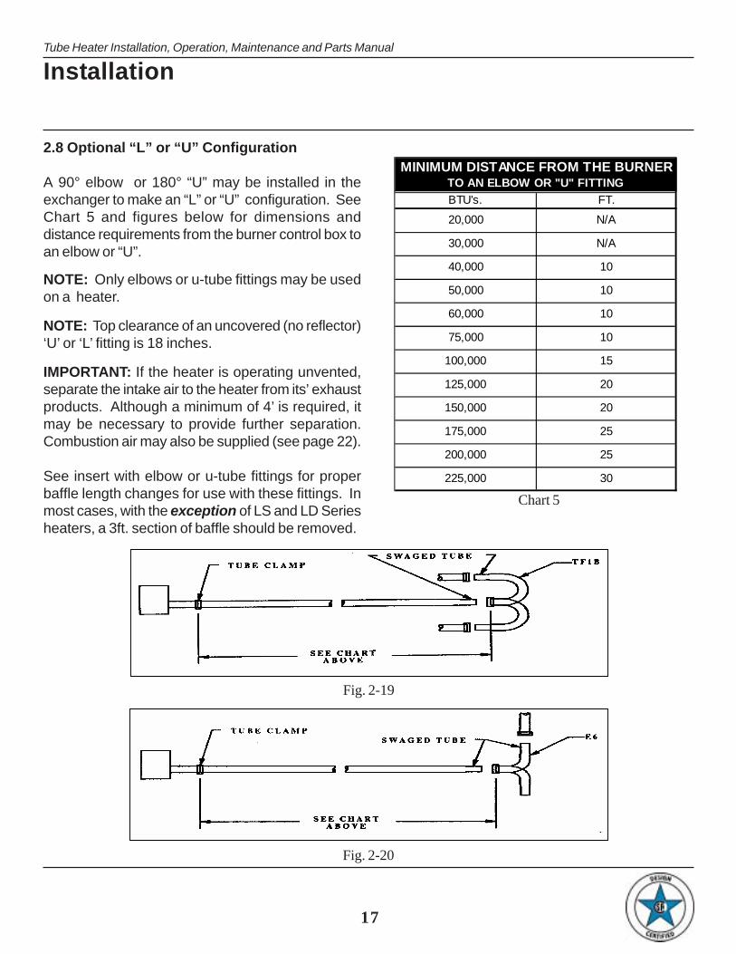
2.8 Optional “L” or “U” Configuration
A 90° elbow or 180° “U” may be installed in theexchanger to make an “L” or “U” configuration. SeeChart 5 and figures below for dimensions anddistance requirements from the burner control box toan elbow or “U”.
NOTE: Only elbows or u-tube fittings may be usedon a heater.
NOTE: Top clearance of an uncovered (no reflector)‘U’ or ‘L’ fitting is 18 inches.
IMPORTANT: If the heater is operating unvented,separate the intake air to the heater from its’ exhaustproducts. Although a minimum of 4’ is required, itmay be necessary to provide further separation.Combustion air may also be supplied (see page 22).
See insert with elbow or u-tube fittings for properbaffle length changes for use with these fittings. Inmost cases, with the exception of LS and LD Seriesheaters, a 3ft. section of baffle should be removed.
Installation
Fig. 2-19
Fig. 2-20
MINIMUM DISTANCE FROM THE BURNER TO AN ELBOW OR "U" FITTING
BTU's. FT.
20,000 N/A
30,000 N/A
40,000 10
50,000 10
60,000 10
75,000 10
100,000 15
125,000 20
150,000 20
175,000 25
200,000 25
225,000 30
Chart 5

504"
214"
272"
156"
330"
388"
446"
373. 9676"
29"
16"
18"
12"
5"
8.125"
16"
18
Tube Heater Installation, Operation, Maintenance and Parts Manual
Tube Heaters
20”
NOTE:WHEN USING THE TF1B ON THE 30', 50' OR 70' HEATERS, ORDER THE 5EASUB. THIS OPTION WILL REPLACE ONE OF THE 10’ TUBE AND REFLECTORSECTIONS WITH TWO SETS OF 5' TUBE AND REFLECTOR SECTIONS (ANDHARDWARE).SEE PAGE 10 FOR U-TUBE CHAIN SET QUANTITIES.
Fig. 2-21 Fig. 2-22
Fig. 2-23
NOTE: information contained on this page applies to 4-inch diameter tube heater models only.

19
Tube Heater Installation, Operation, Maintenance and Parts Manual
Installation
2.9 Flue Venting
The following guidelines must be observed to ensureproper system performance and safety:
• Check all applicable codes prior to installing fluestacks. Local codes may vary. In the absence oflocal codes see the National Fuel Code ANSIZ223.1 (NFPA54) latest edition or the NationalStandards of Canada.
• The heater is designed to operate with a 4 in.diameter exhaust stack (3 in. diameter for LS andLD Series).
• Single wall galvanized flue pipe or Dura/Connectsingle wall, flexible connectors must be used. Theportion of the flue pipe which goes throughcombustible material in the building wall or roofmust transition to a type “B” vent to maintainclearances. See figures 2-24 & 25.
• Maximum vent length for most models is 20 feet.
• The venting system shall terminate at least 3 ft.(0.9m) above any forced air inlet located within10 ft. (3.1m).
• The venting system shall terminate at least 4 ft.(1.2m) below, 4 ft. (1.2m) horizontally from,and/or 1 ft. (30cm) above any door, window, orgravity air inlet into any building. The bottom ofthe vent terminal shall be located at least 12 in.(30 cm) above grade.
• Uninsulated single wall metal pipe shall not beused in cold climates for venting gas utilizationequipment.
• The vent terminal of a horizontal venting systemmust be installed to prevent blockage by snowand protect building materials from degradationby flue gases.
• Stacks that exit the building vertically should be 2ft. above the roof.
• For stacks that exit the building horizontally, theflue should be a minimum of 6 in. from thesidewall. Vent must also extend beyond anycombustible overhang (figure 2-24).
• A common flue of 6 in. diameter (4 in. for LS andLD models) must be used for double venting ofunits. One thermostat must control both units.When common venting, flue should be connectedso that the by-products of one heater cannot flowinto the adjoining flue of the other heater. A dualexhaust assembly is available from DetroitRadiant Products. See figures 2-26 through2-29.
• Separate intake from exhaust by at least 4 feet.Vertical vents should be placed higher thanadjacent intake pipes.
Fig. 2-25
Fig. 2-24

Tube Heaters
20
Tube Heater Installation, Operation, Maintenance and Parts Manual
• Vertical venting may utilize standard “B” vent caps(except for TF9).
• Do not use more than two 90° elbows in theexhaust vent (all models).
• All single wall vent pipes must be sealed with hightemperature sealant and 3 No. 8 sheet metalscrews to prevent leakage of flue gas into thebuilding.
• Horizontal flues (side wall venting) should bepitched down toward outlet, ¼ in. per ft. of thevent length, to prevent rain from entering the heater(see figure 2-26). Do not pitch heater. Verticalvents do not require pitch.
IMPORTANT
Single Heater; Single Vent
Multiple Heaters; Common Roof Vent Multiple Heaters; Common Sidewall Vent
Multiple Heaters; Common Vent at 90°
NOTE: All common vented heaters must share the same thermostat.
Fig. 2-26 Fig. 2-27
Fig. 2-28 Fig. 2-29
(3 IN. FOR LS OR LD SERIES) 4 IN. DIA. GALVANIZEDSTEEL FLUE PIPE (3 IN.FOR LS OR LD SERIES)
6 IN. DIA. GALVANIZEDSTEEL FLUE PIPE (4 IN.FOR LS OR LD SERIES)
6 IN. DIA. VENT CAP (4 IN.FOR LS OR LD SERIES)
6 IN. VENT CAP(4 IN. FOR LS OR LD SERIES)
6 IN. DIA. GALVANIZED STEEL FLUEPIPING (4 IN. FOR LS OR LD SERIES)
DUAL-EXHAUST ASSEMBLY4 IN. DIA. GALVANIZEDSTEEL FLUE PIPING (3 IN.FOR LS OR LD SERIES)
4 IN. DIA. GALVANIZED STEEL FLUEPIPE (3 IN. FOR LS OR LD SERIES)
DUAL EXHAUSTASSEMBLY
4 IN. DIA. GALVANIZED STEEL FLUEPIPE (3 IN. FOR LS OR LD SERIES)
6 IN. DIA. VENT CAP (4 IN.FOR LS OR LD SERIES)
6 IN. DIA. GALVANIZED STEEL FLUEPIPE (4 IN. FOR LS OR LD SERIES)
HEATER

21
Tube Heater Installation, Operation, Maintenance and Parts Manual
2.10 Installation for Unvented Operation - Optional
If propane is used, a positive air displacement of atleast 4.5 CFM per 1000 BTU/H of gas input isrecommended. Either gravity or mechanical meansmay accomplish this air displacement. Provisionsmust be made for a sufficiently large fresh air intakearea and exhaust air outlet area, to accomplish thedisplacement. Local codes may require that themechanical exhaust system be interlocked with theelectrical supply line to the heaters, enabling both tofunction simultaneously.
Installation
Fig. 2-30
(For commercial and industrial installations only. Not for residential use!)
All units are approved for unvented operation whenequipped with a factory supplied end cap/diffuser,Part No. WVE-GALV (WVE-3 for commercial andindustrial LS and LD models) see figure 2-30. Thisallows the products of combustion to be dischargedfrom the unit into the space being heated.
Ventilation of the space is required to dilute thoseproducts of combustion sufficiently. For properventilation, it is recommended that a positive airdisplacement of at least 4.0 CFM per 1000 BTU/Hof natural gas input be provided.

Tube Heaters
22
Tube Heater Installation, Operation, Maintenance and Parts Manual
2.11 Combustion Air Requirements
Combustion air intake has a factory preset air orifice.If indoor combustion air is to be supplied for a tightlyclosed room, one square inch of free air openingshould be provided for each 5,000 BTU/H of heaterinput.
Non-contaminated air for combustion must be ductedto the heater if chlorinated or fluorinated contaminantsare present in the area where the heater is installed,or if the building has a negative pressure. Typicalsources of these contaminants are refrigerants,solvents, adhesives, degreasers, paint removers,paints, lubricants, pesticides, etc.
Outside combustion air may be provided by anaccessory air duct, and directly attached over the airorifice (figures 2-31 & 32). A WIV wall inlet cap mustbe used with horizontal outside air intake ducts. Theuse of flexible 4” hose, connecting the air intake pipeto the heater is recommended to allow flexibility forexpansion. See figure 2-31.
For limitation of length and size, see the Air IntakeDuct-Chart 6. The maximum number of 90° elbowsallowed is two.
Keep intake opening at least 4 ft. from any exhaustvent openings. On rooftop penetrations, always placethe vent stack higher than the air intake stack.
The air intake cap must be installed to preventblockage. Locate WIV air intake by an area that dirt,steam, snow, etc. will not contaminate or clog the ½”intake screen.
NOTE: In humid applications use insulated duct orPVC pipe to prevent condensation on outer surfaceof the intake pipe.
NOTE: Sidewall air intake is preferred over roof airintake.
Fig. 2-31
Flexible Air Inlet Boot 16"
Proper use of flexible air inlet boot & hook-up
4" AirHook-upStnd.
To Outside Sidewall AIR INTAKE DUCT CHARTAIR INTAKE MAXIMUMDUCT SIZE INTAKE LENGTH
MODEL [in.] [ft]ALL 4 20
MODELS 5+ 30
Chart 6
Fig. 2-32

23
Tube Heater Installation, Operation, Maintenance and Parts Manual
2.12 Gas Supply
CAUTION!
CORRECT INLET PRESSURES ARE VITAL FOREFFICIENT OPERATION OF HEATER. REFER TOAGA/CGA(CSA) RATING PLATE AND, IFNECESSARY, CONSULT GAS COMPANY.
If all or a portion of the gas supply line consists ofused pipe, it must be cleaned and then inspected todetermine its equivalency to new pipe. Test all mainsupply lines according to local codes. (Isolateheater gas valve and supplied gas cock duringtest.)
Excessive torque on manifold may misalign orifice.Always use two wrenches when tightening matingpipe connections.
WARNING!Never use a match or any other flame to test for gasleaks. Use a soap and water solution to check for leaks.
If any portion of the gas supply line is located in anarea that could cause an abnormal amount ofcondensate to occur in the pipe, a sediment trapshould be installed (see figure 2-33).
Fig. 2-33
NOTE: For high pressure gas above 14 in. W.C.P.(Water Column Pressure), a high pressure regulatorand gas cock must be used. If compressed air isused to detect leaks in the gas supply line, disconnectand cap shutoff cock to avoid damage to regulatorand gas valve.
A typical gas supply line connection is illustrated infigure 2-33. The method shown will decrease thepossibility of any loose scale or dirt in the supply lineentering the heater’s control system and causing amalfunction. Provide a 1/8 in. (3.2mm) NPT, pluggedtapping accessible for test gauge connectionimmediately up stream of gas connection to heater.The gas supply line must be of sufficient size toprovide the required capacity and inlet pressure tothe heater (consult gas company) as follows:
NOTE: Manifold pressure should be checked at thetap on the gas valve. Readings will be aboveatmospheric pressure.
• Natural Gas
To obtain the required manifold pressure of 3.5in. W.C.P., a minimum inlet pressure of 5.0 in.W.C.P. is necessary for purposes of inputadjustment. A maximum inlet pressure of 14.0 in.W.C.P. is allowed for all units.
• Liquefied Petroleum Gas
To obtain the required manifold pressure of 10.0in. W.C.P., a minimum of 11.0 in. W.C.P. forpurposes of input adjustment to a maximum of14.0 in. W.C.P. must be provided ahead of thecontrol system on each heater. Do not exceed amanifold operating pressure of 10.0 in. W.C.P.
Use only a pipe joint compound that is resistantto liquefied petroleum gases.
• Pressure Equivalents
1 in. W.C.P. equals 0.58 oz/sq. in. = 2.49 Mbar.
Installation
Drip Leg/Sediment Trap
Side View
AGA Ball Valve/Gas Cock
AGA Stainless Flexible Gas Connector
End View

Tube Heaters
24
Tube Heater Installation, Operation, Maintenance and Parts Manual
• Allowance for Expansion
Allowances must be made for the system toexpand. A stainless steel, flexible gas connectoris recommended. If, however, local codes requirerigid piping to the heater, a swing joint can beused.
• Gas Line Connection
a. The gas outlet shall be in the same room asthe appliance and the connector must not beconcealed within or run through any wall, flooror partition.
b. The connector shall be of adequate length.
c. The final assembly shall be tested for leaks.CAUTION: Matches, candles, open flame orother sources of ignition shall not be usedfor this purpose. Leak test solutions maycause corrosion-water rinse after test.
d. Contact with foreign objects or substancesshould be avoided.
e. The connector should not be kinked, twisted ortorqued.
f. Connectors are not designed for movement afterinstallation. Excessive bending, flexing orvibration must be avoided.
Connectors are for use only on piping systemshaving fuel gas pressures not in excess of ½ poundper square inch.
CAUTION!
CONNECTOR NUTS MUST NOT BECONNECTED DIRECTLY TO PIPE THREADS.THIS CONNECTOR MUST BE INSTALLED WITHADAPTORS PROVIDED. DO NOT REUSE.
Fig. 2-34*
*See kit content chart on page 12 of product insert to determine if above piece(s) should be supplied.(Not included on XTS or DES Series heaters.)
1/2” pipe Adapter 24” SS Flex Connector
Appliance Inlet(Note location of tap)Gas Cock

25
Tube Heater Installation, Operation, Maintenance and Parts Manual
3. OPERATION
3.1 Electrical Requirements
See applicable insert for specific instructions.
3.2 Lighting Instructions
1. Purge main gas supply line at start-up.
2. Rotate heater’s manual gas valve knob to the“ON” position.
3. Close electrical circuit.
If heater fails to light, turn off gas and wait fiveminutes before repeating the above procedure.
INSTRUCTIONS POUR L’ALLUMAGE
1. PURGER LA CONDUITE D’ALIMEN-TATION EN GAZ PRINCIPALE.
2. TOURNER LE BOUTON DU ROBINET DEGAZ A COMMANDE MANUELLE JUSQU’ACE QU’IL SE TROUVE EN POSITION DEMARCHE (“ON”).
3. FERMER LE CIRCUIT ELECTRIQUE.
SI L’APPAREIL DE CHAUFFAGE NE S’ALLUMEPAS, ATTENDRE 5 MINUTE AVANT DE SUIVREDE NOUVEAU LES INSTRUCTIONS CI-DESSUS.
QU’IL SE TROUVE EN POSITION D’ARRET(“OFF”).
3.3 Shutdown Instructions
1. Open electrical circuit.
2. Rotate heater’s manual gas valve knob to the"OFF" position.
POUR ETEINDRE L’APPAREIL
1. OUVRIR LE CIRCUIT ELECTRIQUE.
2. TOURNER LE BOUTON DU ROBINET DE GAZ ACOMMANDE MANUELLE DE L’APPAREIL DECHAUFFAGE JUSQU’A CE.
Operation

Tube Heater Installation, Operation, Maintenance and Parts Manual
Date Maintenance Performed Replacement Components Requied
RADIANT TUBE HEATER
4. MAINTENANCE
Infrared heaters require a minimum of routine maintenance to keep them operating at peak performance.
WARNING!
1. Ensure that the squirrel cage in the blower is kept clean. If dirt becomes a problem,installation of outside air intake ducts for combustion is recommended. Oiling the blowermotor will extend bearing life beyond the 30,000 hour minimum.
2. Keep the aluminum reflectors clean.
3. Periodically check the integrity of the combustion tube and heat exchangers. Replace ifthere are signs of structural failure.
26
Tube Heaters
Use protective glasses when cleaning the heater.

27
Tube Heater Installation, Operation, Maintenance and Parts Manual
Maintenance
4.1 TROUBLESHOOTING CHART
S Y M P TO M P O S S IB LE CA US E CO RRE CTIV E A CTIO N1. B lown fus e. 1. Replac e.2. Faulty therm os tat . 2. Replac e.3. Loos e or dis c onnec ted wire. 3. Repair as required.4. Faulty fan. 4. Lubric ate, repair or rep lac e.1. Loos e or dis c onnec ted wire. 1. Repair as required.2. B ox lid or gas k et not in p lac e. 2. P ut in p lac e.3. P lugged pres s ure s witc h lines . 3. C lean as nec es s ary .4. P lugged or res tric ted ex haus t vent . 4. Rem ove fore ign m atter.5. B affle loc ation inc orrec t . 5. Repos it ion baffle at vent end.6. Faulty pres s ure s w itc hes . 6. Replac e only . Do not adjus t .1 . Faulty glo-bar ign itor. 1. Replac e.2. Faulty c irc u it board. 2. Replac e.
1. D is c onnec ted gas va lve w ires . 1. Repair as required.2. Faulty c irc u it board. 2. Replac e.3. Faulty gas va lve. 3. Replac e.
1. Low gas pres s ure. 1. P rovide required gas pres s ure.2. B affle im properly pos it ioned. 2. Repos it ion baffle at vent end.3. Faulty ex haus t pres s ure s w itc h. 3. Replac e.4. Res tric ted flue vent. 4. Rem ove fore ign m at ter.5. No elec t ric a l ground. 5. Connec t e lec tric al ground to junc t ion box .6. Revers ed polarity . 6. Repair.1 . C los ed gas s upply . 1. O pen a ll gas c onnec tions .2. D irty or res tric ted orific e. 2. Rem ove and c lean w ith a s oft ob jec t .3 . Faulty va lve. D is c onnec ted w ire. 3. Replac e or repair.4 . Inle t pres s ure ex c eeds 14" W . C . P . 4. Lower in let pres s ure.1. Low gas pres s ure. 1. P rovide required gas pres s ure.2. D irty or res tric ted orific e. 2. Rem ove and c lean w ith a s oft ob jec t .3 . Fore ign m at ter ins ide burner. 3. C lean as nec es s ary .4. Unit c y c les on and off. 4. Chec k previous s y m ptom .5. Reflec tor is s ooted and has los t its reflec t ive ability .
5. C lean with a lum inum c leaner and a s oft w iping c lo th.
6. Reflec tor not in plac e. 6. P ut in p lac e.7. C logged fan blower. 7. C lean.1. Loos e tube c onnec t ions .
2. Holes or c rac k s in radiant tubes . 2. Replac e.1. S tac k length is too long. 1. S horten s tac k length.2. Light gauge flue s tac k us ed. 2. M inim um of 26 ga. V ent pipe required.3. Contam inated c om bus t ion a ir. 3. P rovide fres h a ir inle t duc t.1 . Ins uffic ient c om bus t ion a ir.
2 . O verfired. 2. Chec k gas pres s ure and orific e s iz e.
Tube bow ing 1. P rovide 2 s q. in. o f free air per 5000 B TU/H of input.
Los s of heater effic ienc y
Radiant tube leak ing burnt gas es . 1. A s s ure the the tube is fu lly ins erted in to flared end and it is properly c lam ped.
Condens ation
Therm os tat c los ed. Fan operates . P res s ure s w itc h ind ic ator light illum inates . No g lo-bar ign itor.Therm os tat c los ed. Fan operates . P res s ure s w itc h ind ic ator light illum inates . G lo-bar energ iz es . No valve light. NO TE: If heater fires , the va lve light is fau lty .
Therm os tat c los ed. Fan and g lo-bar operate. Ign it ion oc c urs . B urner c y c les off. B urner c y lc es on.
Therm os tat c los ed. Fan and g lo-bar operate. A fter 45 s ec onds g lo-bar s huts off. No ignit ion.
GE N E R AL T R O U B L E S H O OT IN G C H AR T
Therm os tat c los ed, fan does not operate.
Therm os tat c los ed. Fan operates . No s witc h ind ic ator light .
NO T E: If g lo-bar ign itor is energiz ed, the ind ic ator light is fau lty .
3 . Contam inated c om bus t ion a ir. 3. P rovide fres h a ir inle t duc t.4 . Heater unable to ex pand properly . 4. Rem ount w ith flex ib le inle t or vent p ipe.
Tube c orroding. 1. Contam inated c om bus t ion a ir. 1. P rovide fres h a ir inle t duc t.1 . D irty or s ooted s ight g las s . 1. Rem ove, c lean or rep lac e.2. Unit m ounted ups ide-down 2. M ount c orrec tly .1 . Ins uffic ient c om bus t ion a ir.
2 . Im proper gas 2. Correc t w ith proper gas input.1. A ddres s ventila t ion c onc erns .
2. A ddres s ventila t ion c onc erns .
3. F ork lifts . 3. A ddres s ventila t ion c onc erns /repair.4 . Loos e tube c onnec t ions . 4. Tighten tube c lam ps to 50-100 ft . lbs .
O dor or fum es in s pac e. 1. V aporiz ed s olvents dec om pos ing when c ontac t ing radiant tubes .2. E vaporation of o ils /s o lvents at floor leve ls .
V is ual ins pec tion of burner operation not pos s ib le.S tac k s oot ing 1. P rovide 1 s q. in. o f free air for every 5000
B TU/H of input

Tube Heater Installation, Operation, Maintenance and Parts Manual
Tube HeatersLimited WarrantyOne-Year Limited Warranty. Radiant Tube Heaters covered in this manual, are warranted by Detroit Radiant ProductsCompany to the original user against defects in workmanship or materials under normal use for one year after date of purchase.Any part which is determined to be defective in material or workmanship and returned to an authorized service location, asDetroit Radiant Products Company designates, shipping costs prepaid, will be, as the exclusive remedy, repaired or replaced atDetroit Radiant Products Company’s option. For limited warranty claim procedures, see PROMPT DISPOSITION below. Thislimited warranty gives purchasers specific legal rights which vary from jurisdiction to jurisdiction.
Additional Limited Warranty. In addition to the above mentioned one-year warranty, Detroit Radiant Products Companywarrants the original purchaser an additional extension on the combustion chamber, radiant tubes and stainless steel burner.This extension excludes electrical/purchased components. See specific product warranties on page 12 of the product manualinsert.
Limitation of Liability. To the extent allowable under applicable law, Detroit Radiant Products Company’s liability forconsequential and incidental damages is expressly disclaimed. Detroit Radiant Products Company’s liability in all events islimited to and shall not exceed the purchase price paid.
Warranty Disclaimer. Detroit Radiant Products Company has made a diligent effort to provide product information andillustrate the products in this literature accurately; however, such information and illustrations are for the sole purpose ofidentification, and do not express or imply a warranty that the products are merchantable, or fit for a particular purpose, or thatthe products will necessarily conform to the illustrations or descriptions. Except as provided below, no warranty or affirmationof fact, expressed or implied, other than as stated in the “LIMITED WARRANTY” above is made or authorized by Detroit RadiantProducts Company.
Product Suitability. Many jurisdictions have codes and regulations governing sales, construction, installation, and/or use ofproducts for certain purposes, which may vary from those in neighboring areas. While Detroit Radiant Products Companyattempts to assure that its products comply with as many codes, it cannot guarantee compliance, and cannot be responsiblefor how the product is installed or used. Before purchase and use of a product, review the product applications, and allapplicable national and local codes and regulations, and be sure that the product, installation, and use will comply with them.
Certain aspects of disclaimers are not applicable to consumer products: e.g., (a) some jurisdictions do not allow the exclusionor limitation of incidental or consequential damages, so the above limitation or exclusion may not apply to you: (b) also, somejurisdictions do not allow a limitation on how long an implied warranty lasts, consequently the above limitation may not apply toyou: and (c) by law, during the period of this limited warranty, any implied warranties of implied merchantability or fitness for aparticular purpose applicable to consumer products purchased by consumers, may not be excluded or otherwise disclaimed.
Prompt Disposition. Detroit Radiant Products Company will make a good faith effort for prompt correction or other adjustmentwith respect to any product which proves to be defective within limited warranty. For any product believed to be defective withinlimited warranty, first write or call dealer from whom the product was purchased. Dealer will give additional directions. If unableto resolve satisfactorily, write to Detroit Radiant Products Company at address below, giving dealer’s name, address, date andnumber of dealer’s invoice, and describe the nature of the defect. Title and risk of loss pass to buyer on delivery to commoncarrier. If product was damaged in transit to you file claim with carrier.
Registration. Register on-line at www.reverberray.com/warranty or mail or fax a completed copy of the manual insert cover.
Detroit Radiant Products Company.21400 Hoover Road Warren, MI 48089 U.S.A.
Voice: (586) 756-0950Fax: (586) 756-2626
Website: www.reverberray.com