Tube Clamp Connectors Linear Actuators - Biotek Kft. · and designed for tubings GN 990 or DIN...
170
Tube Clamp Connectors Linear Actuators
Transcript of Tube Clamp Connectors Linear Actuators - Biotek Kft. · and designed for tubings GN 990 or DIN...

www.elesa-ganter.com
Tube Clamp ConnectorsLinear Actuators
TUBE
CLA
MP
CO
NN
ECTO
RS E
G02
11EN
- C
opyr
ight
© 2
011
ELES
A+
GA
NTE
R 01
/201
1
OTTO GANTER GmbH & Co.KGTriberger Straße 378120 Furtwangen GERMANYPhone: +49 7723 65 07 130Fax: +49 7723 65 07 [email protected]
ELESA S.p.A.Via Pompei 2920052 Monza (Milano) ITALYPhone: +39 039 28 11.1Fax: +39 039 83 63 [email protected]
Distributed by

Standard Machine Elements Worldwide

Picto
rial i
ndex
ELESA and GANTER models all rights reserved in accordance with the law. Always mention the source when reproducing our drawings.
Tube clamp connectors, Linear actuators
GN 131Two-way connector clampsAluminium
page 10
GN 131-NITwo-way connector clampsStainless Steel
page 11
GN 132 Two-way connector clampsAluminium
page 12
GN 133 Two-way connector clampsAluminium
page 14
GN 134 Two-way connector clampsAluminium
page 16
GN 141 Flanged two-way connector clampsAluminium
page 20
GN 145 Flanged connector clampsAluminium
page 22
GN 145-NI Flanged connector clampsStainless Steel
page 23
GN 146 Flanged connector clampsAluminium
page 24
GN 146.3 Flanged connector clampsAluminium
page 26
GN 147Flanged connector clampsAluminium
page 28
GN 162Base plate connector clampsAluminium
page 30
GN 162-NIBase plate connector clampsStainless Steel
page 31
GN 163Base plate connector clampsAluminium
page 32
GN 165Base plate connector clampsAluminium
page 34
GN 166Off-set base plate connector clampsAluminium
page 36
GN 167Wide base plate connector clampsAluminium
page 38
GN 171Flanged base plate connector clampsAluminium
page 40
GN 191T-Angle connector clampsAluminium
page 44
GN 191-NIT-Angle connector clampsStainless Steel
page 44
GN 192T-Angle connector clampsAluminium
page 48
GN 193T-Angle connector clampsAluminium
page 48
GN 194T-Angle connector clampsAluminium
page 51
GN 195T-Angle connector clampsAluminium
page 54
GN 231Tube supportsAluminium
page 56
GN 241Tube connectorsAluminium
page 58
GN 242Tube connectorsAluminium
page 60
2

Picto
rial i
ndex
ELESA and GANTER models all rights reserved in accordance with the law. Always mention the source when reproducing our drawings.
Tube clamp connectors, Linear actuators
GN 271Swivel clamp connector basesAluminium
page 63
GN 272Swivel clamp connector basesAluminium
page 64
GN 273Swivel clamp connectorsAluminium
page 65
GN 274Swivel clamp connectorsAluminium
page 66
GN 275Swivel clamp connectorsAluminium
page 69
GN 276Swivel clamp connectorsAluminium
page 70
GN 277Swivel clamp connectorsAluminium
page 73
GN 278Swivel clamp connectorsAluminium
page 74
GN 281Swivel clamp connector jointsAluminium
page 77
GN 282Swivel clamp connector jointsAluminium
page 80
GN 283Swivel clamp connector jointsAluminium
page 82
GN 284Swivel clamp connector jointsAluminium
page 84
GN 285Swivel clamp connector jointsAluminium
page 88
GN 286Swivel clamp connector jointsAluminium
page 90
GN 287Swivel clamp connector jointsAluminium
page 94
GN 288Swivel clamp connector jointsAluminium
page 96
GN 271.4Sensor holdersAluminium
page 100
GN 272.4Sensor holdersAluminium
page 101
GN 273.4Sensor holdersAluminium
page 102
GN 990-NIConstruction tubingsStainless Steel
page 103
GN 990Construction tubingsSteel, Aluminium
page 104
GN 991Tube end plugsTechnopolymer
page 106
GN 911Clamping kitsStainless Steel
page 110
GN 992Insert bushesAluminium
page 108
GN 291Linear actuatorsSteel, Stainless Steel
page 113
GN 292Linear actuatorsSteel, Stainless Steel
page 116
GN 293Linear actuatorsSteel, Stainless Steel
page 117
3

Picto
rial i
ndex
ELESA and GANTER models all rights reserved in accordance with the law. Always mention the source when reproducing our drawings.
Tube clamp connectors, Linear actuators
GN 131.1Linear actuator connectorsAluminium
page 120
GN 131.1-NILinear actuator connectors Stainless Steel
page 121
GN 131.2Linear actuator connectors Aluminium
page 122
GN 131.2-NILinear actuator connectors Stainless Steel
page 123
GN 132.1Linear actuator connectors Aluminium
page 124
GN 132.2Linear actuator connectors Aluminium
page 126
GN 145.1Flanged linear actuator connectors Aluminium
page 128
GN 145.1-NIFlanged linear actuator connectors Stainless Steel
page 129
GN 146.1Flanged linear actuator connectors Aluminium
page 130
GN 162.1Base plate linear actuator connectors Aluminium
page 131
GN 162.1-NIBase plate linear actuator connectors Stainless Steel
page 132
GN 163.1Base plate linear actuator connectors Aluminium
page 133
GN 191.1T-Angle linear actuator connectors Aluminium
page 134
GN 191.1-NIT-Angle linear actuator connectors Stainless Steel
page 135
GN 192.1T-Angle linear actuator connectors Aluminium
page 136
GN 273.1Swivel clamp linear actuator connectors Aluminium
page 137
GN 274.1Swivel clamp linear actuator connectors Aluminium
page138
GN 291.1Square linear actuatorsSteel
page 140
GN 147.1Flanged linear actuator connectors Aluminium
page 143
GN 134.1Two-way linear actuator connectors Aluminium
page 144
GN 165.1Base plate linear actuator connectors Aluminium
page 145
GN 923.18Handwheel for linear actuator Ø 18
page 147
GN 923.30Handwheel for linear actuator Ø 30 and 30
page 148
GN 923.40Handwheel for linear actuator Ø 40 and 40
page 149
GN 924.40Handwheel for linear actuator Ø 40 and 40
page 150
GN 924.50Handwheel for linear actuator Ø 50 and 50
page 151
GN 924.60Handwheel for linear actuator Ø 60 and 60
page 152
4

Picto
rial i
ndex
ELESA and GANTER models all rights reserved in accordance with the law. Always mention the source when reproducing our drawings.
Tube clamp connectors, Linear actuators
GN 295Installation kits for position indicators usedon linear actuators
page 153
GN 299Longitudinal scales for linear actuators
page 154
GN 391Transfer units Steel
page 157
GN 391-NITransfer units Stainless Steel
page 158
GN 297Bevel gear wheels Steel
page 159
GN 298 Housings for angular gears / T-gears Aluminium
page 160
5
Two-way connector clamps page 10
Flanged two-way connector clamps page 20
Flanged connector clamps page 22
Base plate connector clamps page 30
Flanged base plate connector clamps page 40
T-angle connector clamps page 42
Tube connectors page 56
Swivel clamp connectors page 63
Swivel clamp connector joints page 77
Sensor holders page 100
Linear actuators page 113 / 140
Tube
cla
mp
conn
ecto
rs, L
inea
r ac
tuat
ors
ELESA and GANTER models all rights reserved in accordance with the law. Always mention the source when reproducing our drawings.
6
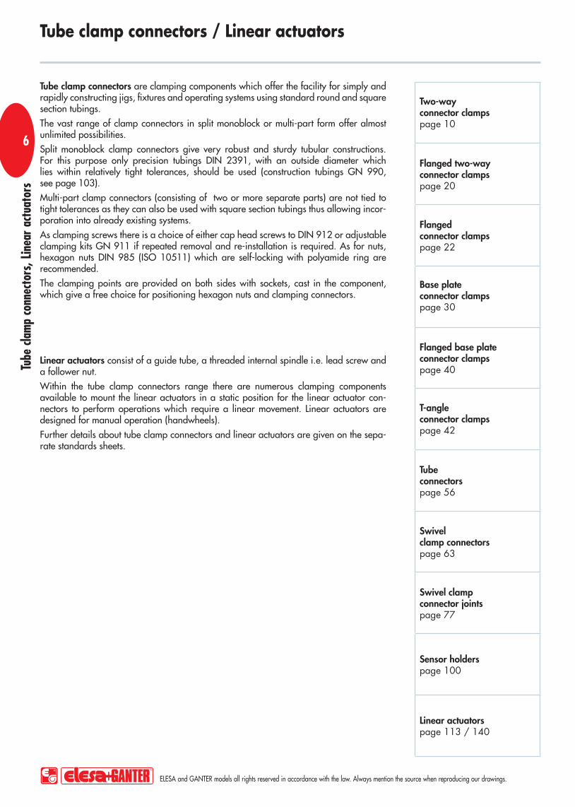
Tube clamp connectors are clamping components which offer the facility for simply and rapidly constructing jigs, fixtures and operating systems using standard round and square section tubings.
The vast range of clamp connectors in split monoblock or multi-part form offer almost unlimited possibilities.
Split monoblock clamp connectors give very robust and sturdy tubular constructions. For this purpose only precision tubings DIN 2391, with an outside diameter which lies within relatively tight tolerances, should be used (construction tubings GN 990, see page 103).
Multi-part clamp connectors (consisting of two or more separate parts) are not tied to tight tolerances as they can also be used with square section tubings thus allowing incor-poration into already existing systems.
As clamping screws there is a choice of either cap head screws to DIN 912 or adjustable clamping kits GN 911 if repeated removal and re-installation is required. As for nuts, hexagon nuts DIN 985 (ISO 10511) which are self-locking with polyamide ring are recommended.
The clamping points are provided on both sides with sockets, cast in the component, which give a free choice for positioning hexagon nuts and clamping connectors.
Tube clamp connectors / Linear actuators
Linear actuators consist of a guide tube, a threaded internal spindle i.e. lead screw and a follower nut.
Within the tube clamp connectors range there are numerous clamping components available to mount the linear actuators in a static position for the linear actuator con-nectors to perform operations which require a linear movement. Linear actuators are designed for manual operation (handwheels).
Further details about tube clamp connectors and linear actuators are given on the sepa-rate standards sheets.

Tube
cla
mp
conn
ecto
rs, L
inea
r ac
tuat
ors
ELESA and GANTER models all rights reserved in accordance with the law. Always mention the source when reproducing our drawings.
7
Design shapes of tube clamp connectors / linear actuators

Tube
cla
mp
conn
ecto
rs, L
inea
r ac
tuat
ors
ELESA and GANTER models all rights reserved in accordance with the law. Always mention the source when reproducing our drawings.
8
Installation examples of tube clamp connectors
Mobile lifting table
GN 147GN 193
GN 132
GN 146.1
GN 291

Tube
cla
mp
conn
ecto
rs, L
inea
r ac
tuat
ors
ELESA and GANTER models all rights reserved in accordance with the law. Always mention the source when reproducing our drawings.
9
Installation examples of tube clamp connectors

1
Tube
cla
mp
conn
ecto
rs, L
inea
r ac
tuat
ors
ELESA and GANTER models all rights reserved in accordance with the law. Always mention the source when reproducing our drawings.
1010
Features and applicationsThe clamping bores of the two-way connector clamps GN 131 are machined and designed for tubings GN 990 or DIN 2391, DIN 2395 and DIN 2462 respectively.Accessories- Tubings GN 990 (see page 103ff.).- Clamping kits GN 911 (clamping handles GN 300.1 with distance bushing
see page 110.Special executions on request (For sufficient quantities)Different combinations of bores d1/d2.
MaterialAluminium.Finish- Version SW: RAL 9005 black colour, matte finish, epoxy resin coating.- Version BL: blank, matte shot-blasted.Clamping screws- Identification no. 1: with two clamping screws DIN 912 and nuts
DIN 985, zinc-plated.- Identification no. 2: with two AISI 304 stainless steel-clamping screws
DIN 912 and nuts DIN 985.AssemblyThe standard clamping bolts are socket cap screws DIN 912, supplied assembled. They can be replaced by clamping kits GN 911 (description see table of dimensions).
Two-way connector clamps
GN 131
* Complete the description of the standard item needed by adding the finish of the connector clamps: BL (blank) or SW (black).
Standard Elements Main dimensionsClamping kits
for d3Description d1 d2 k Clamping length
d3 l m g
GN 131-B10-B10-1-* B10 B10 25 M6 64 20 GN 911-M6-22 85
GN 131-B12-B12-1-* B12 B12 25 M6 64 20 GN 911-M6-22 80
GN 131-B14-B14-1-* B14 B14 25 M6 64 20 GN 911-M6-22 79
GN 131-B15-B15-1-* B15 B15 25 M6 64 20 GN 911-M6-22 76
GN 131-B16-B16-1-* B16 B16 25 M6 64 20 GN 911-M6-22 70
GN 131-B18-B18-1-* B18 B18 25 M6 64 20 GN 911-M6-22 68
GN 131-B10-B10-2-* B10 B10 25 M6 64 20 GN 911-M6-22 85
GN 131-B12-B12-2-* B12 B12 25 M6 64 20 GN 911-M6-22 80
GN 131-B14-B14-2-* B14 B14 25 M6 64 20 GN 911-M6-22 79
GN 131-B15-B15-2-* B15 B15 25 M6 64 20 GN 911-M6-22 76
GN 131-B16-B16-2-* B16 B16 25 M6 64 20 GN 911-M6-22 70
GN 131-B18-B18-2-* B18 B18 25 M6 64 20 GN 911-M6-22 68

Tube
cla
mp
conn
ecto
rs, L
inea
r ac
tuat
ors
ELESA and GANTER models all rights reserved in accordance with the law. Always mention the source when reproducing our drawings.
11
Standard Elements Main dimensionsClamping kits
for d3Description d1 d2 k Clamping length
d3 l m g
GN 131-B12-B12-2-NI B12 B12 25 M6 64 20 GN 911-M6-22 203
GN 131-B14-B14-2-NI B14 B14 25 M6 64 20 GN 911-M6-22 190
GN 131-B16-B16-2-NI B16 B16 25 M6 64 20 GN 911-M6-22 170
GN 131-B18-B18-2-NI B18 B18 25 M6 64 20 GN 911-M6-22 148
GN 131-B20-B20-2-NI B20 B20 25 M6 64 20 GN 911-M6-22 144
Features and applicationsThe clamping bores of the two-way connector clamps GN 131-NI are machined and designed for tubings GN 990 or DIN 2391, DIN 2395 and DIN 2462 respectively.Accessories- Tubings GN 990 (see page 103ff.).- Clamping kits GN 911 (clamping handles GN 300.1 with distance bushing)
see page 110.Special executions on request (For sufficient quantities)Different combinations of bores d1/d2.
MaterialAISI CF-8 stainless steel NI, matte polished.Clamping screwsIdentification no. 2: with two AISI 304 stainless steel-clamping screws DIN 912 and nuts DIN 985.AssemblyThe standard clamping bolts are socket cap screws DIN 912, supplied assembled. They can be replaced by clamping kits GN 911 (description see table of dimensions).
Two-way connector clamps
GN 131-NI

1
Tube
cla
mp
conn
ecto
rs, L
inea
r ac
tuat
ors
ELESA and GANTER models all rights reserved in accordance with the law. Always mention the source when reproducing our drawings.
1212
Features and applicationsThe clamping bores of the two-way connector clamps GN 132 are machined and designed for tubings GN 990 or DIN 2391, DIN 2395 and DIN 2462 respectively.Accessories- Tubings GN 990 (see page 103ff.) . - Clamping kits GN 911 (clamping handles GN 300.1 with distance bushing)
see page 110.Special executions on request (For sufficient quantities)Different combinations of bores d1/d2.
MaterialAluminium.Finish- Version SW: RAL 9005 black colour, matte finish, epoxy resin coating. - Version BL: blank, matte shot-blasted.Clamping screws- Identification no. 1: with two clamping screws DIN 912 and nuts
DIN 985, zinc-plated.- Identification no. 2: with two AISI 304 stainless steel-clamping screws
DIN 912 and nuts DIN 985.AssemblyThe standard clamping bolts are socket cap screws DIN 912, supplied assembled. They can be replaced by clamping kits GN 911 (description see table of dimensions).
GN 132Two-way connector clamps

Tube
cla
mp
conn
ecto
rs, L
inea
r ac
tuat
ors
ELESA and GANTER models all rights reserved in accordance with the law. Always mention the source when reproducing our drawings.
13
Standard Elements Main dimensionsClamping kits
for d3Description d1 d2 k Clamping length
d3 l1 l2 m g
GN 132-B20-B20-40-1-* B20 B20 40 M8 97 40 33 GN 911-M8-32 215
GN 132-B25-B25-40-1-* B25 B25 40 M8 97 40 33 GN 911-M8-32 192
GN 132-B30-B30-40-1-* B30 B30 40 M8 97 40 33 GN 911-M8-32 170
GN 132-B30-B30-56-1-* B30 B30 56 M10 125 56 45 GN 911-M10-40 570
GN 132-B32-B32-56-1-* B32 B32 56 M10 125 56 45 GN 911-M10-40 535
GN 132-B35-B35-56-1-* B35 B35 56 M10 125 56 45 GN 911-M10-40 500
GN 132-B40-B40-56-1-* B40 B40 56 M10 125 56 45 GN 911-M10-40 417
GN 132-B40-B40-65-1-* B40 B40 65 M10 143 65 53 GN 911-M10-55 835
GN 132-B42-B42-65-1-* B42 B42 65 M10 143 65 53 GN 911-M10-55 780
GN 132-B45-B45-65-1-* B45 B45 65 M10 143 65 53 GN 911-M10-55 732
GN 132-B48-B48-65-1-* B48 B48 65 M10 143 65 53 GN 911-M10-55 670
GN 132-B50-B50-65-1-* B50 B50 65 M10 143 65 53 GN 911-M10-55 630
GN 132-B50-B50-80-1-* B50 B50 80 M10 169 80 65 GN 911-M10-55 1460
GN 132-B55-B55-80-1-* B55 B55 80 M10 169 80 65 GN 911-M10-55 1260
GN 132-B60-B60-80-1-* B60 B60 80 M10 169 80 65 GN 911-M10-55 1060
GN 132-B20-B20-40-2-* B20 B20 40 M8 97 40 33 GN 911-M8-32 215
GN 132-B25-B25-40-2-* B25 B25 40 M8 97 40 33 GN 911-M8-32 192
GN 132-B30-B30-40-2-* B30 B30 40 M8 97 40 33 GN 911-M8-32 170
GN 132-B30-B30-56-2-* B30 B30 56 M10 125 56 45 GN 911-M10-40 570
GN 132-B32-B32-56-2-* B32 B32 56 M10 125 56 45 GN 911-M10-40 535
GN 132-B35-B35-56-2-* B35 B35 56 M10 125 56 45 GN 911-M10-40 500
GN 132-B40-B40-56-2-* B40 B40 56 M10 125 56 45 GN 911-M10-40 417
GN 132-B40-B40-65-2-* B40 B40 65 M10 143 65 53 GN 911-M10-55 835
GN 132-B42-B42-65-2-* B42 B42 65 M10 143 65 53 GN 911-M10-55 780
GN 132-B45-B45-65-2-* B45 B45 65 M10 143 65 53 GN 911-M10-55 732
GN 132-B48-B48-65-2-* B48 B48 65 M10 143 65 53 GN 911-M10-55 670
GN 132-B50-B50-65-2-* B50 B50 65 M10 143 65 53 GN 911-M10-55 630
GN 132-B50-B50-80-2-* B50 B50 80 M10 169 80 65 GN 911-M10-55 1460
GN 132-B55-B55-80-2-* B55 B55 80 M10 169 80 65 GN 911-M10-55 1260
GN 132-B60-B60-80-2-* B60 B60 80 M10 169 80 65 GN 911-M10-55 1060
* Complete the description of the standard item needed by adding the finish of the connector clamps: BL (blank) or SW (black).

1
Tube
cla
mp
conn
ecto
rs, L
inea
r ac
tuat
ors
ELESA and GANTER models all rights reserved in accordance with the law. Always mention the source when reproducing our drawings.
1414
Features and applicationsThe clamping bores of the two-way connector clamps GN 133 are machined and designed for construction tubings GN 990 or DIN 2391, DIN 2395 and DIN 2462 respectively.Accessories- Tubings GN 990 (see page 103ff.). - Clamping kits GN 911 (clamping handles GN 300.1 with distance bushing)
see page 110.Special executions on request (For sufficient quantities)Different combinations of bores d1/d2.
MaterialAluminium.Finish- Version SW: RAL 9005 black colour, matte finish, epoxy resin coating.- Version BL: blank, matte shot-blasted.Clamping screws- Identification no. 1: with two clamping screws DIN 912 and nuts
DIN 985, zinc-plated.- Identification no. 2: with two AISI 304 stainless steel-clamping screws
DIN 912 and nuts DIN 985.AssemblyThe standard clamping bolts are socket cap screws DIN 912, supplied assembled. They can be replaced by clamping kits GN 911 (description see table of dimensions).
Two-way connector clamps
GN 133
Standard Elements Main dimensions Clamping kitsfor d3 for d4Description d1 d2 d3 d4 k1 k2 l1 l2 l3 m g
GN 133-B20-B12-1-* B20 B12 M8 M6 40 36 81.5 40 26 27 GN 911-M8-32 GN 911-M6-25 177
GN 133-B20-B14-1-* B20 B14 M8 M6 40 36 81.5 40 26 27 GN 911-M8-32 GN 911-M6-25 174
GN 133-B20-B16-1-* B20 B16 M8 M6 40 36 81.5 40 26 27 GN 911-M8-32 GN 911-M6-25 169
GN 133-B20-B18-1-* B20 B18 M8 M6 40 36 81.5 40 26 27 GN 911-M8-32 GN 911-M6-25 165
GN 133-B25-B12-1-* B25 B12 M8 M6 40 36 81.5 40 26 27 GN 911-M8-32 GN 911-M6-25 160
GN 133-B25-B14-1-* B25 B14 M8 M6 40 36 81.5 40 26 27 GN 911-M8-32 GN 911-M6-25 156
GN 133-B25-B16-1-* B25 B16 M8 M6 40 36 81.5 40 26 27 GN 911-M8-32 GN 911-M6-25 151
GN 133-B25-B18-1-* B25 B18 M8 M6 40 36 81.5 40 26 27 GN 911-M8-32 GN 911-M6-25 136
* Complete the description of the standard item needed by adding the finish of the connector clamps: BL (blank) or SW (black).

Tube
cla
mp
conn
ecto
rs, L
inea
r ac
tuat
ors
ELESA and GANTER models all rights reserved in accordance with the law. Always mention the source when reproducing our drawings.
15
Standard Elements Main dimensions Clamping kitsfor d3 for d4Description d1 d2 d3 d4 k1 k2 l1 l2 l3 m g
GN 133-B30-B12-1-* B30 B12 M8 M6 40 36 81.5 40 26 27 GN 911-M8-32 GN 911-M6-25 135
GN 133-B30-B14-1-* B30 B14 M8 M6 40 36 81.5 40 26 27 GN 911-M8-32 GN 911-M6-25 133
GN 133-B30-B16-1-* B30 B16 M8 M6 40 36 81.5 40 26 27 GN 911-M8-32 GN 911-M6-25 128
GN 133-B30-B18-1-* B30 B18 M8 M6 40 36 81.5 40 26 27 GN 911-M8-32 GN 911-M6-25 124
GN 133-B40-B20-1-* B40 B20 M10 M8 65 59 122 65 40 45 GN 911-M10-55 GN 911-M8-32 640
GN 133-B40-B25-1-* B40 B25 M10 M8 65 59 122 65 40 45 GN 911-M10-55 GN 911-M8-32 601
GN 133-B40-B30-1-* B40 B30 M10 M8 65 59 122 65 40 45 GN 911-M10-55 GN 911-M8-32 569
GN 133-B42-B20-1-* B42 B20 M10 M8 65 59 122 65 40 45 GN 911-M10-55 GN 911-M8-32 603
GN 133-B42-B25-1-* B42 B25 M10 M8 65 59 122 65 40 45 GN 911-M10-55 GN 911-M8-32 578
GN 133-B42-B30-1-* B42 B30 M10 M8 65 59 122 65 40 45 GN 911-M10-55 GN 911-M8-32 547
GN 133-B45-B20-1-* B45 B20 M10 M8 65 59 122 65 40 45 GN 911-M10-55 GN 911-M8-32 567
GN 133-B45-B25-1-* B45 B25 M10 M8 65 59 122 65 40 45 GN 911-M10-55 GN 911-M8-32 542
GN 133-B45-B30-1-* B45 B30 M10 M8 65 59 122 65 40 45 GN 911-M10-55 GN 911-M8-32 511
GN 133-B48-B20-1-* B48 B20 M10 M8 65 59 122 65 40 45 GN 911-M10-55 GN 911-M8-32 533
GN 133-B48-B25-1-* B48 B25 M10 M8 65 59 122 65 40 45 GN 911-M10-55 GN 911-M8-32 508
GN 133-B48-B30-1-* B48 B30 M10 M8 65 59 122 65 40 45 GN 911-M10-55 GN 911-M8-32 477
GN 133-B50-B20-1-* B50 B20 M10 M8 65 59 122 65 40 45 GN 911-M10-55 GN 911-M8-32 506
GN 133-B50-B25-1-* B50 B25 M10 M8 65 59 122 65 40 45 GN 911-M10-55 GN 911-M8-32 481
GN 133-B50-B30-1-* B50 B30 M10 M8 65 59 122 65 40 45 GN 911-M10-55 GN 911-M8-32 450
GN 133-B20-B12-2-* B20 B2 M8 M6 40 36 81.5 40 26 27 GN 911-M8-32 GN 911-M6-25 180
GN 133-B20-B14-2-* B20 B14 M8 M6 40 36 81.5 40 26 27 GN 911-M8-32 GN 911-M6-25 174
GN 133-B20-B16-2-* B20 B16 M8 M6 40 36 81.5 40 26 27 GN 911-M8-32 GN 911-M6-25 170
GN 133-B20-B18-2-* B20 B18 M8 M6 40 36 81.5 40 26 27 GN 911-M8-32 GN 911-M6-25 170
GN 133-B25-B12-2-* B25 B12 M8 M6 40 36 81.5 40 26 27 GN 911-M8-32 GN 911-M6-25 159
GN 133-B25-B14-2-* B25 B14 M8 M6 40 36 81.5 40 26 27 GN 911-M8-32 GN 911-M6-25 155
GN 133-B25-B16-2-* B25 B16 M8 M6 40 36 81.5 40 26 27 GN 911-M8-32 GN 911-M6-25 150
GN 133-B25-B18-2-* B25 B18 M8 M6 40 36 81.5 40 26 27 GN 911-M8-32 GN 911-M6-25 147
GN 133-B30-B12-2-* B30 B12 M8 M6 40 36 81.5 40 26 27 GN 911-M8-32 GN 911-M6-25 135
GN 133-B30-B14-2-* B30 B14 M8 M6 40 36 81.5 40 26 27 GN 911-M8-32 GN 911-M6-25 128
GN 133-B30-B16-2-* B30 B16 M8 M6 40 36 81.5 40 26 27 GN 911-M8-32 GN 911-M6-25 128
GN 133-B30-B18-2-* B30 B18 M8 M6 40 36 81.5 40 26 27 GN 911-M8-32 GN 911-M6-25 124
GN 133-B40-B20-2-* B40 B20 M10 M8 65 59 122 65 40 45 GN 911-M10-55 GN 911-M8-32 640
GN 133-B40-B25-2-* B40 B25 M10 M8 65 59 122 65 40 45 GN 911-M10-55 GN 911-M8-32 601
GN 133-B40-B30-2-* B40 B30 M10 M8 65 59 122 65 40 45 GN 911-M10-55 GN 911-M8-32 570
GN 133-B42-B20-2-* B42 B20 M10 M8 65 59 122 65 40 45 GN 911-M10-55 GN 911-M8-32 600
GN 133-B42-B25-2-* B42 B25 M10 M8 65 59 122 65 40 45 GN 911-M10-55 GN 911-M8-32 600
GN 133-B42-B30-2-* B42 B30 M10 M8 65 59 122 65 40 45 GN 911-M10-55 GN 911-M8-32 600
GN 133-B45-B20-2-* B45 B20 M10 M8 65 59 122 65 40 45 GN 911-M10-55 GN 911-M8-32 510
GN 133-B45-B25-2-* B45 B25 M10 M8 65 59 122 65 40 45 GN 911-M10-55 GN 911-M8-32 510
GN 133-B45-B30-2-* B45 B30 M10 M8 65 59 122 65 40 45 GN 911-M10-55 GN 911-M8-32 510
GN 133-B48-B20-2-* B48 B20 M10 M8 65 59 122 65 40 45 GN 911-M10-55 GN 911-M8-32 475
GN 133-B48-B25-2-* B48 B25 M10 M8 65 59 122 65 40 45 GN 911-M10-55 GN 911-M8-32 475
GN 133-B48-B30-2-* B48 B30 M10 M8 65 59 122 65 40 45 GN 911-M10-55 GN 911-M8-32 475
GN 133-B50-B20-2-* B50 B20 M10 M8 65 59 122 65 40 45 GN 911-M10-55 GN 911-M8-32 505
GN 133-B50-B25-2-* B50 B25 M10 M8 65 59 122 65 40 45 GN 911-M10-55 GN 911-M8-32 480
GN 133-B50-B30-2-* B50 B30 M10 M8 65 59 122 65 40 45 GN 911-M10-55 GN 911-M8-32 450
* Complete the description of the standard item needed by adding the finish of the connector clamps: BL (blank) or SW (black).

1
Tube
cla
mp
conn
ecto
rs, L
inea
r ac
tuat
ors
ELESA and GANTER models all rights reserved in accordance with the law. Always mention the source when reproducing our drawings.
1616
Features and applicationsThe clamping bores of the two-way connector clamps GN 134 are not machi-ned and designed for construction tubings GN 990 or DIN 2391, DIN 2395 and DIN 2462 respectively.Within the same nominal size the two-way connector clamps can be supplied with the bores d1 and d2 and square bores s1 and s2 i.e. in combination with d1 and s2 or s1 and d2.Accessories- Tubings GN 990 (see page 103ff.). - Clamping kits GN 911 (clamping handles GN 300.1 with distance bushing)
see page 110.
MaterialAluminium.Finish- Version SW: RAL 9005 black colour, matte finish, epoxy resin coating. - Version BL: blank, matte shot-blasted.Clamping screws- Identification no. 1: with four clamping screws DIN 912 and nuts
DIN 985, zinc-plated.- Identification no. 2: with four AISI 304 stainless steel-clamping screws
DIN 912 and nuts DIN 985.AssemblyThe standard clamping bolts are socket cap screws DIN 912, supplied assembled. They can be replaced by clamping kits GN 911 (description see table of dimensions).
Two-way connector clamps
GN 134

Tube
cla
mp
conn
ecto
rs, L
inea
r ac
tuat
ors
ELESA and GANTER models all rights reserved in accordance with the law. Always mention the source when reproducing our drawings.
17Standard Elements Main dimensions
Clamping kitsfor d3Description d1 s1 d2 s2 k
Clamping lengthd3 l1 l2 m g
GN 134-B20-B20-50-1-* B20 - B20 - 50 M8 79.5 68 33.5 GN 911-M8-35 355
GN 134-B25-B25-50-1-* B25 - B25 - 50 M8 79.5 68 33.5 GN 911-M8-35 340
GN 134-B30-B30-50-1-* B30 - B30 - 50 M8 79.5 68 33.5 GN 911-M8-35 325
GN 134-B30-B30-60-1-* B30 - B30 - 60 M8 109 79 50 GN 911-M8-55 690
GN 134-B32-B32-60-1-* B32 - B32 - 60 M8 109 79 50 GN 911-M8-55 670
GN 134-B35-B35-60-1-* B35 - B35 - 60 M8 109 79 50 GN 911-M8-55 670
GN 134-B40-B40-60-1-* B40 - B40 - 60 M8 109 79 50 GN 911-M8-55 610
GN 134-B40-B40-76-1-* B40 - B40 - 76 M10 125 98 55 GN 911-M10-63 975
GN 134-B42-B42-76-1-* B42 - B42 - 76 M10 125 98 55 GN 911-M10-63 945
GN 134-B45-B45-76-1-* B45 - B45 - 76 M10 125 98 55 GN 911-M10-63 930
GN 134-B48-B48-76-1-* B48 - B48 - 76 M10 125 98 55 GN 911-M10-63 915
GN 134-B50-B50-76-1-* B50 - B50 - 76 M10 125 98 55 GN 911-M10-63 885
GN 134-B20-V20-50-1-* B20 - - V20 50 M8 79.5 68 33.5 GN 911-M8-35 350
GN 134-B25-V25-50-1-* B25 - - V25 50 M8 79.5 68 33.5 GN 911-M8-35 330
GN 134-B30-V30-50-1-* B30 - - V30 50 M8 79.5 68 33.5 GN 911-M8-35 310
GN 134-B30-V30-60-1-* B30 - - V30 60 M8 109 79 50 GN 911-M8-55 680
GN 134-B35-V35-60-1-* B35 - - V35 60 M8 109 79 50 GN 911-M8-55 640
GN 134-B40-V40-60-1-* B40 - - V40 60 M8 109 79 50 GN 911-M8-55 580
GN 134-B40-V40-76-1-* B40 - - V40 76 M10 125 98 55 GN 911-M10-63 890
GN 134-B45-V45-76-1-* B45 - - V45 76 M10 125 98 55 GN 911-M10-63 835
GN 134-B50-V50-76-1-* B50 - - V50 76 M10 125 98 55 GN 911-M10-63 770
GN 134-V20-V20-50-1-* - V20 - V20 50 M8 79.5 68 33.5 GN 911-M8-35 351
GN 134-V25-V25-50-1-* - V25 - V25 50 M8 79.5 68 33.5 GN 911-M8-35 325
GN 134-V30-V30-50-1-* - V30 - V30 50 M8 79.5 68 33.5 GN 911-M8-35 300
GN 134-V30-V30-60-1-* - V30 - V30 60 M8 109 79 50 GN 911-M8-55 660
GN 134-V35-V35-60-1-* - V35 - V35 60 M8 109 79 50 GN 911-M8-55 620
GN 134-V40-V40-60-1-* - V40 - V40 60 M8 109 79 50 GN 911-M8-55 560
GN 134-V40-V40-76-1-* - V40 - V40 76 M10 125 98 55 GN 911-M10-63 945
GN 134-V45-V45-76-1-* - V45 - V45 76 M10 125 98 55 GN 911-M10-63 895
GN 134-V50-V50-76-1-* - V50 - V50 76 M10 125 98 55 GN 911-M10-63 825
GN 134-V20-B20-50-1-* - V20 B20 - 50 M8 79.5 68 33.5 GN 911-M8-35 350
GN 134-V25-B25-50-1-* - V25 B25 - 50 M8 79.5 68 33.5 GN 911-M8-35 330
GN 134-V30-B30-50-1-* - V30 B30 - 50 M8 79.5 68 33.5 GN 911-M8-35 310
GN 134-V30-B30-60-1-* - V30 B30 - 60 M8 109 79 50 GN 911-M8-55 680
GN 134-V35-B35-60-1-* - V35 B35 - 60 M8 109 79 50 GN 911-M8-55 640
GN 134-V40-B40-60-1-* - V40 B40 - 60 M8 109 79 50 GN 911-M8-55 580
GN 134-V40-B40-76-1-* - V40 B40 - 76 M10 125 98 55 GN 911-M10-63 890
GN 134-V45-B45-76-1-* - V45 B45 - 76 M10 125 98 55 GN 911-M10-63 835
GN 134-V50-B50-76-1-* - V50 B50 - 76 M10 125 98 55 GN 911-M10-63 770
* Complete the description of the standard item needed by adding the finish of the connector clamps: BL (blank) or SW (black).

1
Tube
cla
mp
conn
ecto
rs, L
inea
r ac
tuat
ors
ELESA and GANTER models all rights reserved in accordance with the law. Always mention the source when reproducing our drawings.
1818
Standard Elements Main dimensionsClamping kits
for d3Description d1 Bore B
s1 Square V
d2 Bore B
s2 Square V
k Clamping length
d3 l1 l2 m g
GN 134-B20-B20-50-2-* B20 - B20 - 50 M8 79.5 68 33.5 GN 911-M8-35 355
GN 134-B25-B25-50-2-* B25 - B25 - 50 M8 79.5 68 33.5 GN 911-M8-35 330
GN 134-B30-B30-50-2-* B30 - B30 - 50 M8 79.5 68 33.5 GN 911-M8-35 320
GN 134-B30-B30-60-2-* B30 - B30 - 60 M8 109 79 50 GN 911-M8-55 700
GN 134-B32-B32-60-2-* B32 - B32 - 60 M8 109 79 50 GN 911-M8-55 690
GN 134-B35-B35-60-2-* B35 - B35 - 60 M8 109 79 50 GN 911-M8-55 680
GN 134-B40-B40-60-2-* B40 - B40 - 60 M8 109 79 50 GN 911-M8-55 620
GN 134-B40-B40-76-2-* B40 - B40 - 76 M10 125 98 55 GN 911-M10-63 890
GN 134-B42-B42-76-2-* B42 - B42 - 76 M10 125 98 55 GN 911-M10-63 945
GN 134-B45-B45-76-2-* B45 - B45 - 76 M10 125 98 55 GN 911-M10-63 915
GN 134-B48-B48-76-2-* B48 - B48 - 76 M10 125 98 55 GN 911-M10-63 915
GN 134-B50-B50-76-2-* B50 - B50 - 76 M10 125 98 55 GN 911-M10-63 885
GN 134-V20-V20-50-2-* - V20 - V20 50 M8 79.5 68 33.5 GN 911-M8-35 350
GN 134-V25-V25-50-2-* - V25 - V25 50 M8 79.5 68 33.5 GN 911-M8-35 325
GN 134-V30-V30-50-2-* - V30 - V30 50 M8 79.5 68 33.5 GN 911-M8-35 300
GN 134-V30-V30-60-2-* - V30 - V30 60 M8 109 79 50 GN 911-M8-55 660
GN 134-V35-V35-60-2-* - V35 - V35 60 M8 109 79 50 GN 911-M8-55 620
GN 134-V40-V40-60-2-* - V40 - V40 60 M 8 109 79 50 GN 911-M8-55 560
GN 134-V40-V40-76-2-* - V40 - V40 76 M 10 125 98 55 GN 911-M10-63 945
GN 134-V45-V45-76-2-* - V45 - V45 76 M 10 125 98 55 GN 911-M10-63 825
GN 134-V50-V50-76-2-* - V50 - V50 76 M 10 125 98 55 GN 911-M10-63 825
GN 134-V20-B20-50-2-* - V20 B20 - 50 M 8 79.5 68 33.5 GN 911-M8-35 350
GN 134-V25-B25-50-2-* - V25 B25 - 50 M 8 79.5 68 33.5 GN 911-M8-35 330
GN 134-V30-B30-50-2-* - V30 B30 - 50 M 8 79.5 68 33.5 GN 911-M8-35 310
GN 134-V30-B30-60-2-* - V30 B30 - 60 M 8 109 79 50 GN 911-M8-55 680
GN 134-V35-B35-60-2-* - V35 B35 - 60 M 8 109 79 50 GN 911-M8-55 640
GN 134-V40-B40-60-2-* - V40 B40 - 60 M 8 109 79 50 GN 911-M8-55 580
GN 134-V40-B40-76-2-* - V40 B40 - 76 M 10 125 98 55 GN 911-M10-63 890
GN 134-V45-B45-76-2-* - V45 B45 - 76 M 10 125 98 55 GN 911-M10-63 835
GN 134-V50-B50-76-2-* - V50 B50 - 76 M 10 125 98 55 GN 911-M10-63 840
* Complete the description of the standard item needed by adding the finish of the connector clamps: BL (blank) or SW (black).

Tube
cla
mp
conn
ecto
rs, L
inea
r ac
tuat
ors
ELESA and GANTER models all rights reserved in accordance with the law. Always mention the source when reproducing our drawings.
19
Two-way connector clamps GN 131 (see page 10) Stainless Steel-Two-way connector clamps GN 131 (see page 11) Two-way connector clamps GN 132 (see page 12) Two-way connector clamps GN 133 (see page 14) Two-way connector clamps GN 134 (see page 16) Flanged two-way connector clamps GN 141 (see page 20)

1
Tube
cla
mp
conn
ecto
rs, L
inea
r ac
tuat
ors
ELESA and GANTER models all rights reserved in accordance with the law. Always mention the source when reproducing our drawings.
2020
Features and applicationsThe clamping bores of the flanged two-way connector clamps GN 141 are not machined and designed for construction tubings GN 990 or DIN 2391, DIN 2395 and DIN 2462 respectively.Within the same nominal size the flanged two-way connector clamps can be supplied with the bores d1 and d2 and square bores s1 and s2 i.e. in combina-tion with d1 and s2 or s1 and d2.Accessories- Tubings GN 990 (see page 103ff.).- Clamping kits GN 911 (clamping handles GN 300.1 with distance bushing)
see page 110.
MaterialAluminium.Finish- Version SW: RAL 9005 black colour, matte finish, epoxy resin coating.- Version BL: blank, matte shot-blasted.Clamping screws- Identification no. 1: with four clamping screws DIN 912 and nuts
DIN 985, zinc-plated.- Identification no. 2: with four AISI 304 stainless steel-clamping screws
DIN 912 and nuts DIN 985.AssemblyThe standard clamping bolts are socket cap screws DIN 912, supplied assembled. They can be replaced by clamping kits GN 911 (description see table of dimensions).
Flanged two-way connector clamps
GN 141
Standard Elements Main dimensionsClamping kits
for d4Description d1 s1 d2 s2 d3 d4 k Clamping length
l1 l2 l3 m t x1 x2 y1 y2 g
GN 141-B20-B20-1-* B20 - B20 - 6.5 M8 50 89 30 68 36 7 75 60 50 35 GN 911-M8-35 402
GN 141-B25-B25-1-* B25 - B25 - 6.5 M8 50 89 30 68 36 7 75 60 50 35 GN 911-M8-35 386
GN 141-B30-B30-1-* B30 - B30 - 6.5 M8 50 89 30 68 36 7 75 60 50 35 GN 911-M8-35 368
GN 141-B40-B40-1-* B40 - B40 - 11 M10 76 136 46 98 55 14 115 90 76 50 GN 911-M10-63 1118
GN 141-B42-B42-1-* B42 - B42 - 11 M10 76 136 46 98 55 14 115 90 76 50 GN 911-M10-63 1094
GN 141-B45-B45-1-* B45 - B45 - 11 M10 76 136 46 98 55 14 115 90 76 50 GN 911-M10-63 1074
GN 141-B48-B48-1-* B48 - B48 - 11 M10 76 136 46 98 55 14 115 90 76 50 GN 911-M10-63 1059
GN 141-B50-B50-1-* B50 - B50 - 11 M10 76 136 46 98 55 14 115 90 76 50 GN 911-M10-63 1031
* Complete the description of the standard item needed by adding the finish of the connector clamps: BL (blank) or SW (black).

Tube
cla
mp
conn
ecto
rs, L
inea
r ac
tuat
ors
ELESA and GANTER models all rights reserved in accordance with the law. Always mention the source when reproducing our drawings.
21
Standard Elements Main dimensionsClamping kits
for d4Description d1 s1 d2 s2 d3 d4 k Clamping length
l1 l2 l3 m t x1 x2 y1 y2 g
GN 141-B20-V20-1-* B20 - - V20 6.5 M8 50 89 30 68 36 7 75 60 50 35 GN 911-M8-35 395
GN 141-B25-V25-1-* B25 - - V25 6.5 M8 50 89 30 68 36 7 75 60 50 35 GN 911-M8-35 374
GN 141-B30-V30-1-* B30 - - V30 6.5 M8 50 89 30 68 36 7 75 60 50 35 GN 911-M8-35 355
GN 141-B40-V40-1-* B40 - - V40 11 M10 76 136 46 98 55 14 115 90 76 50 GN 911-M10-63 1002
GN 141-B45-V45-1-* B45 - - V45 11 M10 76 136 46 98 55 14 115 90 76 50 GN 911-M10-63 946
GN 141-B50-V50-1-* B50 - - V50 11 M10 76 136 46 98 55 14 115 90 76 50 GN 911-M10-63 922
GN 141-V20-V20-1-* - V20 - V20 6.5 M8 50 89 30 68 36 7 75 60 50 35 GN 911-M8-35 392
GN 141-V25-V25-1-* - V25 - V25 6.5 M8 50 89 30 68 36 7 75 60 50 35 GN 911-M8-35 368
GN 141-V30-V30-1-* - V30 - V30 6.5 M8 50 89 30 68 36 7 75 60 50 35 GN 911-M8-35 339
GN 141-V40-V40-1-* - V40 - V40 11 M10 76 136 46 98 55 14 115 90 76 50 GN 911-M10-63 1091
GN 141-V45-V45-1-* - V45 - V45 11 M10 76 136 46 98 55 14 115 90 76 50 GN 911-M10-63 1040
GN 141-V50-V50-1-* - V50 - V50 11 M10 76 136 46 98 55 14 115 90 76 50 GN 911-M10-63 975
GN 141-V20-B20-1-* - V20 B20 - 6.5 M8 50 89 30 68 36 7 75 60 50 35 GN 911-M8-35 396
GN 141-V25-B25-1-* - V25 B25 - 6.5 M8 50 89 30 68 36 7 75 60 50 35 GN 911-M8-35 375
GN 141-V30-B30-1-* - V30 B30 - 6.5 M8 50 89 30 68 36 7 75 60 50 35 GN 911-M8-35 356
GN 141-V40-B40-1-* - V40 B40 - 11 M10 76 136 46 98 55 14 115 90 76 50 GN 911-M10-63 1034
GN 141-V45-B45-1-* - V45 B45 - 11 M10 76 136 46 98 55 14 115 90 76 50 GN 911-M10-63 980
GN 141-V50-B50-1-* - V50 B50 - 11 M10 76 136 46 98 55 14 115 90 76 50 GN 911-M10-63 959
GN 141-B20-B20-2-* B20 - B20 - 6.5 M8 50 89 30 68 36 7 75 60 50 35 GN 911-M8-35 402
GN 141-B25-B25-2-* B25 - B25 - 6.5 M8 50 89 30 68 36 7 75 60 50 35 GN 911-M8-35 386
GN 141-B30-B30-2-* B30 - B30 - 6.5 M8 50 89 30 68 36 7 75 60 50 35 GN 911-M8-35 368
GN 141-B40-B40-2-* B40 - B40 - 11 M10 76 136 46 98 55 14 115 90 76 50 GN 911-M10-63 1118
GN 141-B42-B42-2-* B42 - B42 - 11 M10 76 136 46 98 55 14 115 90 76 50 GN 911-M10-63 1094
GN 141-B45-B45-2-* B45 - B45 - 11 M10 76 136 46 98 55 14 115 90 76 50 GN 911-M10-63 1074
GN 141-B48-B48-2-* B48 - B48 - 11 M10 76 136 46 98 55 14 115 90 76 50 GN 911-M10-63 1059
GN 141-B50-B50-2-* B50 - B50 - 11 M10 76 136 46 98 55 14 115 90 76 50 GN 911-M10-63 1031
GN 141-B20-V20-2-* B20 - - V20 6.5 M8 50 89 30 68 36 7 75 60 50 35 GN 911-M8-35 395
GN 141-B25-V25-2-* B25 - - V25 6.5 M8 50 89 30 68 36 7 75 60 50 35 GN 911-M8-35 374
GN 141-B30-V30-2-* B30 - - V30 6.5 M8 50 89 30 68 36 7 75 60 50 35 GN 911-M8-35 355
GN 141-B40-V40-2-* B40 - - V40 11 M10 76 136 46 98 55 14 115 90 76 50 GN 911-M10-63 1002
GN 141-B45-V45-2-* B45 - - V45 11 M10 76 136 46 98 55 14 115 90 76 50 GN 911-M10-63 946
GN 141-B50-V50-2-* B50 - - V50 11 M10 76 136 46 98 55 14 115 90 76 50 GN 911-M10-63 922
GN 141-V20-V20-2-* - V20 - V20 6.5 M8 50 89 30 68 36 7 75 60 50 35 GN 911-M8-35 392
GN 141-V25-V25-2-* - V25 - V25 6.5 M8 50 89 30 68 36 7 75 60 50 35 GN 911-M8-35 368
GN 141-V30-V30-2-* - V30 - V30 6.5 M8 50 89 30 68 36 7 75 60 50 35 GN 911-M8-35 339
GN 141-V40-V40-2-* - V40 - V40 11 M10 76 136 46 98 55 14 115 90 76 50 GN 911-M10-63 1091
GN 141-V45-V45-2-* - V45 - V45 11 M10 76 136 46 98 55 14 115 90 76 50 GN 911-M10-63 1040
GN 141-V50-V50-2-* - V50 - V50 11 M10 76 136 46 98 55 14 115 90 76 50 GN 911-M10-63 975
GN 141-V20-B20-2-* - V20 B20 - 6.5 M8 50 89 30 68 36 7 75 60 50 35 GN 911-M8-35 396
GN 141-V25-B25-2-* - V25 B25 - 6.5 M8 50 89 30 68 36 7 75 60 50 35 GN 911-M8-35 375
GN 141-V30-B30-2-* - V30 B30 - 6.5 M8 50 89 30 68 36 7 75 60 50 35 GN 911-M8-35 356
GN 141-V40-B40-2-* - V40 B40 - 11 M10 76 136 46 98 55 14 115 90 76 50 GN 911-M10-63 1034
GN 141-V45-B45-2-* - V45 B45 - 11 M10 76 136 46 98 55 14 115 90 76 50 GN 911-M10-63 980
GN 141-V50-B50-2-* - V50 B50 - 11 M10 76 136 46 98 55 14 115 90 76 50 GN 911-M10-63 959
* Complete the description of the standard item needed by adding the finish of the connector clamps: BL (blank) or SW (black).

1
Tube
cla
mp
conn
ecto
rs, L
inea
r ac
tuat
ors
ELESA and GANTER models all rights reserved in accordance with the law. Always mention the source when reproducing our drawings.
2222
Features and applicationsThe clamping bores of the flanged connector clamps GN 145 are machined and designed for construction tubings GN 990 or DIN 2391, DIN 2395 and DIN 2462 respectively.Accessories- Tubings GN 990 (see page 1093ff.). - Clamping kits GN 911 (clamping handles GN 300.1 with distance bushing)
see page 110.
MaterialAluminium.Finish- Version SW: RAL 9005 black colour, matte finish, epoxy resin coating. - Version BL: blank, matte shot-blasted.Clamping screw- Identification no. 1: with clamping screw DIN 912 and nut DIN 985,
zinc-plated.- Identification no. 2: with AISI 304 stainless steel-clamping screw
DIN 912 and nut DIN 985.AssemblyThe standard clamping bolts are socket cap screws DIN 912, supplied assembled. They can be replaced by clamping kits GN 911 (description see table of dimensions).
Flanged connector clamps
GN 145
Standard Elements Main dimensionsClamping kits
for d3Description d1 d2 d3 k Clamping length
l1 l2 m t x y1 y2 g
GN 145-B10-1-* B10 5.5 M6 25 40 25 18 7 35 50 38 GN 911-M6-22 71
GN 145-B12-1-* B12 5.5 M6 25 40 25 18 7 35 50 38 GN 911-M6-22 69
GN 145-B14-1-* B14 5.5 M6 25 40 25 18 7 35 50 38 GN 911-M6-22 67
GN 145-B15-1-* B15 5.5 M6 25 40 25 18 7 35 50 38 GN 911-M6-22 65
GN 145-B16-1-* B16 5.5 M6 25 40 25 18 7 35 50 38 GN 911-M6-22 64
GN 145-B18-1-* B18 5.5 M6 25 40 25 18 7 35 50 38 GN 911-M6-22 60
GN 145-B10-2-* B10 5.5 M6 25 40 25 18 7 35 50 38 GN 911-M6-22 71
GN 145-B12-2-* B12 5.5 M6 25 40 25 18 7 35 50 38 GN 911-M6-22 69
GN 145-B14-2-* B14 5.5 M6 25 40 25 18 7 35 50 38 GN 911-M6-22 67
GN 145-B15-2-* B15 5.5 M6 25 40 25 18 7 35 50 38 GN 911-M6-22 67
GN 145-B16-2-* B16 5.5 M6 25 40 25 18 7 35 50 38 GN 911-M6-22 64
GN 145-B18-2-* B18 5.5 M 6 25 40 25 18 7 35 50 38 GN 911-M6-22 60
* Complete the description of the standard item needed by adding the finish of the connector clamps: BL (blank) or SW (black).

Tube
cla
mp
conn
ecto
rs, L
inea
r ac
tuat
ors
ELESA and GANTER models all rights reserved in accordance with the law. Always mention the source when reproducing our drawings.
23
Standard Elements Main dimensionsClamping kits
for d3Description d1 d2 d3 k Clamping length
l1 l2 m t x y1 y2 g
GN 145-B12-2-NI B12 5.5 M6 25 40 25 18 7 35 50 38 GN 911-M6-22 177
GN 145-B14-2-NI B14 5.5 M6 25 40 25 18 7 35 50 38 GN 911-M6-22 170
GN 145-B15-2-NI B15 5.5 M6 25 40 25 18 7 35 50 38 GN 911-M6-22 170
GN 145-B16-2-NI B16 5.5 M6 25 40 25 18 7 35 50 38 GN 911-M6-22 164
GN 145-B18-2-NI B18 5.5 M6 25 40 25 18 7 35 50 38 GN 911-M6-22 159
Features and applicationsThe clamping bores of the flanged connector clamps GN 145-NI are machined and designed for construction tubings GN 990 or DIN 2391, DIN 2395 and DIN 2462 respectively.Accessories- Tubings GN 990 (see page 103ff.). - Clamping kits GN 911 (clamping handles GN 300.1 with distance bushing)
see page 110.
MaterialAISI CF-8 stainless steel NI, matte polished.Clamping screwIdentification no. 2: with AISI 304 stainless steel-clamping screw DIN 912 and nut DIN 985.AssemblyThe standard clamping bolts are socket cap screws DIN 912, supplied assembled. They can be replaced by clamping kits GN 911 (description see table of dimensions).
Flanged connector clamps
GN 145-NI

1
Tube
cla
mp
conn
ecto
rs, L
inea
r ac
tuat
ors
ELESA and GANTER models all rights reserved in accordance with the law. Always mention the source when reproducing our drawings.
2424
Features and applicationsThe clamping bores of the flanged connector clamps GN 146 are machined and designed for construction tubings GN 990 or DIN 2391, DIN 2395 and DIN 2462 respectively.Accessories- Tubings GN 990 (see page 103ff.). - Clamping kits GN 911 (clamping handles GN 300.1 with distance bushing)
see page 110.
MaterialAluminium.Finish- Version SW: RAL 9005 black colour, matte finish, epoxy resin coating. - Version BL: blank, matte shot-blasted.Clamping screw- Identification no. 1: with clamping screw DIN 912 and nut DIN 985,
zinc-plated.- Identification no. 2: with AISI 304 stainless steel-clamping screw
DIN 912 and nut DIN 985.AssemblyThe standard clamping bolts are socket cap screws DIN 912, supplied assembled. They can be replaced by clamping kits GN 911 (description see table of dimensions).
Flanged connector clamps
GN 146

Tube
cla
mp
conn
ecto
rs, L
inea
r ac
tuat
ors
ELESA and GANTER models all rights reserved in accordance with the law. Always mention the source when reproducing our drawings.
25
Standard Elements Main dimensionsClamping kits
for d3Description d1 k Clamping length
d2 d3 l1 l2 m t x1 x2 y1 y2 g
GN 146-B20-40-1-* B20 40 6.5 M8 62 40 30 7 52 35 70 53 GN 911-M8-32 194
GN 146-B25-40-1-* B25 40 6.5 M8 62 40 30 7 52 35 70 53 GN 911-M8-32 179
GN 146-B30-40-1-* B30 40 6.5 M8 62 40 30 7 52 35 70 53 GN 911-M8-32 159
GN 146-B30-56-1-* B30 56 8.5 M10 83 56 42 10 78 52 108 82 GN 911-M10-40 511
GN 146-B32-56-1-* B32 56 8.5 M10 83 56 42 10 78 52 108 82 GN 911-M10-40 476
GN 146-B35-56-1-* B35 56 8.5 M10 83 56 42 10 78 52 108 82 GN 911-M10-40 480
GN 146-B40-56-1-* B40 56 8.5 M10 83 56 42 10 78 52 108 82 GN 911-M10-40 438
GN 146-B40-65-1-* B40 65 11 M10 95 65 50 14 92 62 128 98 GN 911-M10-55 794
GN 146-B42-65-1-* B42 65 11 M10 95 65 50 14 92 62 128 98 GN 911-M10-55 764
GN 146-B45-65-1-* B45 65 11 M10 95 65 50 14 92 62 128 98 GN 911-M10-55 736
GN 146-B48-65-1-* B48 65 11 M10 95 65 50 14 92 62 128 98 GN 911-M10-55 694
GN 146-B50-65-1-* B50 65 11 M10 95 65 50 14 92 62 128 98 GN 911-M10-55 683
GN 146-B50-80-1-* B50 80 11 M10 112 80 60 14 110 74 154 118 GN 911-M10-55 1320
GN 146-B55-80-1-* B55 80 11 M10 112 80 60 14 110 74 154 118 GN 911-M10-55 1220
GN 146-B60-80-1-* B60 80 11 M10 112 80 60 14 110 74 154 118 GN 911-M10-55 1120
GN 146-B20-40-2-* B20 40 6.5 M8 62 40 30 7 52 35 70 53 GN 911-M8-32 194
GN 146-B25-40-2-* B25 40 6.5 M8 62 40 30 7 52 35 70 53 GN 911-M8-32 179
GN 146-B30-40-2-* B30 40 6.5 M8 62 40 30 7 52 35 70 53 GN 911-M8-32 159
GN 146-B30-56-2-* B30 56 8.5 M10 83 56 42 10 78 52 108 82 GN 911-M10-40 510
GN 146-B32-56-2-* B32 56 8.5 M10 83 56 42 10 78 52 108 82 GN 911-M10-40 476
GN 146-B35-56-2-* B35 56 8.5 M10 83 56 42 10 78 52 108 82 GN 911-M10-40 480
GN 146-B40-56-2-* B40 56 8.5 M10 83 56 42 10 78 52 108 82 GN 911-M10-40 435
GN 146-B40-65-2-* B40 65 11 M10 95 65 50 14 92 62 128 98 GN 911-M10-55 794
GN 146-B42-65-2-* B42 65 11 M10 95 65 50 14 92 62 128 98 GN 911-M10-55 760
GN 146-B45-65-2-* B45 65 11 M10 95 65 50 14 92 62 128 98 GN 911-M10-55 736
GN 146-B48-65-2-* B48 65 11 M10 95 65 50 14 92 62 128 98 GN 911-M10-55 694
GN 146-B50-65-2-* B50 65 11 M10 95 65 50 14 92 62 128 98 GN 911-M10-55 680
GN 146-B50-80-2-* B50 80 11 M10 112 80 60 14 110 74 154 118 GN 911-M10-55 1320
GN 146-B55-80-2-* B55 80 11 M10 112 80 60 14 110 74 154 118 GN 911-M10-55 1120
GN 146-B60-80-2-* B60 80 11 M10 112 80 60 14 110 74 154 118 GN 911-M10-55 1120
* Complete the description of the standard item needed by adding the finish of the connector clamps: BL (blank) or SW (black).
1
Tube
cla
mp
conn
ecto
rs, L
inea
r ac
tuat
ors
ELESA and GANTER models all rights reserved in accordance with the law. Always mention the source when reproducing our drawings.
2626
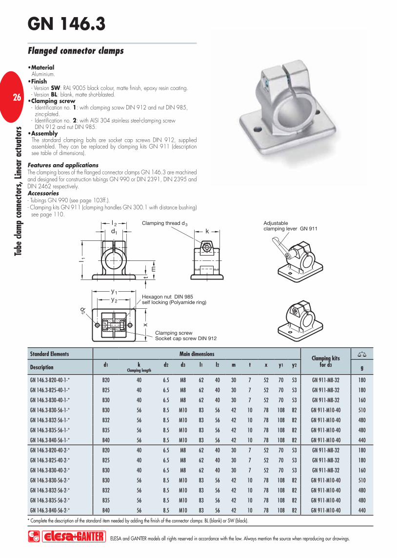
Features and applicationsThe clamping bores of the flanged connector clamps GN 146.3 are machined and designed for construction tubings GN 990 or DIN 2391, DIN 2395 and DIN 2462 respectively.Accessories- Tubings GN 990 (see page 103ff.).- Clamping kits GN 911 (clamping handles GN 300.1 with distance bushing)
see page 110.
MaterialAluminium.Finish- Version SW: RAL 9005 black colour, matte finish, epoxy resin coating. - Version BL: blank, matte shot-blasted.Clamping screw- Identification no. 1: with clamping screw DIN 912 and nut DIN 985,
zinc-plated.- Identification no. 2: with AISI 304 stainless steel-clamping screw
DIN 912 and nut DIN 985.AssemblyThe standard clamping bolts are socket cap screws DIN 912, supplied assembled. They can be replaced by clamping kits GN 911 (description see table of dimensions).
Flanged connector clamps
GN 146.3
Standard Elements Main dimensionsClamping kits
for d3Description d1 k Clamping length
d2 d3 l1 l2 m t x y1 y2 g
GN 146.3-B20-40-1-* B20 40 6.5 M8 62 40 30 7 52 70 53 GN 911-M8-32 180
GN 146.3-B25-40-1-* B25 40 6.5 M8 62 40 30 7 52 70 53 GN 911-M8-32 180
GN 146.3-B30-40-1-* B30 40 6.5 M8 62 40 30 7 52 70 53 GN 911-M8-32 160
GN 146.3-B30-56-1-* B30 56 8.5 M10 83 56 42 10 78 108 82 GN 911-M10-40 510
GN 146.3-B32-56-1-* B32 56 8.5 M10 83 56 42 10 78 108 82 GN 911-M10-40 480
GN 146.3-B35-56-1-* B35 56 8.5 M10 83 56 42 10 78 108 82 GN 911-M10-40 480
GN 146.3-B40-56-1-* B40 56 8.5 M10 83 56 42 10 78 108 82 GN 911-M10-40 440
GN 146.3-B20-40-2-* B20 40 6.5 M8 62 40 30 7 52 70 53 GN 911-M8-32 180
GN 146.3-B25-40-2-* B25 40 6.5 M8 62 40 30 7 52 70 53 GN 911-M8-32 180
GN 146.3-B30-40-2-* B30 40 6.5 M8 62 40 30 7 52 70 53 GN 911-M8-32 160
GN 146.3-B30-56-2-* B30 56 8.5 M10 83 56 42 10 78 108 82 GN 911-M10-40 510
GN 146.3-B32-56-2-* B32 56 8.5 M10 83 56 42 10 78 108 82 GN 911-M10-40 480
GN 146.3-B35-56-2-* B35 56 8.5 M10 83 56 42 10 78 108 82 GN 911-M10-40 480
GN 146.3-B40-56-2-* B40 56 8.5 M10 83 56 42 10 78 108 82 GN 911-M10-40 440
* Complete the description of the standard item needed by adding the finish of the connector clamps: BL (blank) or SW (black).

Tube
cla
mp
conn
ecto
rs, L
inea
r ac
tuat
ors
ELESA and GANTER models all rights reserved in accordance with the law. Always mention the source when reproducing our drawings.
27
Flanged connector clamps GN 145 (see page 22) Stainless-Steel-Flanged connector clamps GN 145 (see page 22) Flanged connector clamps GN 146 (see page 24) Flanged connector clamps GN 146.3 (see page 26) Flanged connector clamps GN 147 (see page 28)

1
Tube
cla
mp
conn
ecto
rs, L
inea
r ac
tuat
ors
ELESA and GANTER models all rights reserved in accordance with the law. Always mention the source when reproducing our drawings.
2828
Features and applicationsThe clamping bores of the flanged connector clamps GN 147 are not machined and designed for construction tubings GN 990 or DIN 2391, DIN 2395 and DIN 2462 respectively.Accessories- Tubings GN 990 (see page 103ff.).- Clamping kits GN 911 (clamping handles GN 300.1 with distance bushing)
see page 110.
MaterialAluminium.Finish- Version SW: RAL 9005 black colour, matte finish, epoxy resin coating. - Version BL: blank, matte shot-blasted. Clamping screws- Identification no. 1: with two clamping screws DIN 912 and nuts
DIN 985, zinc-plated.- Identification no. 2: with two AISI 304 stainless steel-clamping screws
DIN 912 and nuts DIN 985.AssemblyThe standard clamping bolts are socket cap screws DIN 912, supplied assembled. They can be replaced by clamping kits GN 911 (description see table of dimensions).
Flanged connector clamps
GN 147

Tube
cla
mp
conn
ecto
rs, L
inea
r ac
tuat
ors
ELESA and GANTER models all rights reserved in accordance with the law. Always mention the source when reproducing our drawings.
29
Standard Elements Main dimensionsClamping kits
for d3Description d1 s d2 d3 k Clamping length
l1 l2 m t x1 x2 y1 y2 g
GN 147 B20-1-* B20 - 6.5 M8 50 53 68 30 7 50 35 75 60 GN 911-M8-45 247
GN 147-B25-1-* B25 - 6.5 M8 50 53 68 30 7 50 35 75 60 GN 911-M8-45 240
GN 147-B30-1-* B30 - 6.5 M8 50 53 68 30 7 50 35 75 60 GN 911-M8-45 232
GN 147-B40-1-* B40 - 11 M10 76 81.5 98 46.5 14 76 50 115 90 GN 911-M10-70 665
GN 147-B42-1-* B42 - 11 M10 76 81.5 98 46.5 14 76 50 115 90 GN 911-M10-70 680
GN 147-B45-1-* B45 - 11 M10 76 81.5 98 46.5 14 76 50 115 90 GN 911-M10-70 640
GN 147-B48-1-* B48 - 11 M10 76 81.5 98 46.5 14 76 50 115 90 GN 911-M10-70 631
GN 147-B50-1-* B50 - 11 M10 76 81.5 98 46.5 14 76 50 115 90 GN 911-M10-70 620
GN 147-V20-1-* - V20 6.5 M8 50 53 68 30 7 50 35 75 60 GN 911-M8-45 242
GN 147-V25-1-* - V25 6.5 M8 50 53 68 30 7 50 35 75 60 GN 911-M8-45 233
GN 147-V30-1-* - V30 6.5 M8 50 53 68 30 7 50 35 75 60 GN 911-M8-45 221
GN 147-V40-1-* - V40 11 M10 76 81.5 98 46.5 14 76 50 115 90 GN 911-M10-70 643
GN 147-V45-1-* - V45 11 M10 76 81.5 98 46.5 14 76 50 115 90 GN 911-M10-70 625
GN 147-V50-1-* - V50 11 M10 76 81.5 98 46.5 14 76 50 115 90 GN 911-M10-70 595
GN 147-B20-2-* B20 - 6.5 M8 50 53 68 30 7 50 35 75 60 GN 911-M8-45 245
GN 147-B25-2-* B25 - 6.5 M8 50 53 68 30 7 50 35 75 60 GN 911-M8-45 240
GN 147-B30-2-* B30 - 6.5 M8 50 53 68 30 7 50 35 75 60 GN 911-M8-45 188
GN 147-B40-2-* B40 - 11 M10 76 81.5 98 46.5 14 76 50 115 90 GN 911-M10-70 665
GN 147-B42-2-* B42 - 11 M10 76 81.5 98 46.5 14 76 50 115 90 GN 911-M10-70 650
GN 147-B45-2-* B45 - 11 M10 76 81.5 98 46.5 14 76 50 115 90 GN 911-M10-70 640
GN 147-B48-2-* B48 - 11 M10 76 81.5 98 46.5 14 76 50 115 90 GN 911-M10-70 631
GN 147-B50-2-* B50 - 11 M10 76 81.5 98 46.5 14 76 50 115 90 GN 911-M10-70 620
GN 147-V20-2-* - V20 6.5 M8 50 53 68 30 7 50 35 75 60 GN 911-M10-70 242
GN 147-V25-2-* - V25 6.5 M8 50 53 68 30 7 50 35 75 60 GN 911-M8-45 230
GN 147-V30-2-* - V30 6.5 M8 50 53 68 30 7 50 35 75 60 GN 911-M8-45 221
GN 147-V40-2-* - V40 11 M10 76 81.5 98 46.5 14 76 50 115 90 GN 911-M10-70 643
GN 147-V45-2-* - V45 11 M10 76 81.5 98 46.5 14 76 50 115 90 GN 911-M10-70 625
GN 147-V50-2-* - V50 11 M10 76 81.5 98 46.5 14 76 50 115 90 GN 911-M10-70 595
* Complete the description of the standard item needed by adding the finish of the connector clamps: BL (blank) or SW (black).

1
Tube
cla
mp
conn
ecto
rs, L
inea
r ac
tuat
ors
ELESA and GANTER models all rights reserved in accordance with the law. Always mention the source when reproducing our drawings.
3030
Features and applicationsThe clamping bores of the base plate connector clamps GN 162 are machined and designed for construction tubings GN 990 or DIN 2391, DIN 2395 and DIN 2462 respectively.Accessories- Tubings GN 990 (see page 103ff.).- Clamping kits GN 911(clamping handles GN 300.1 with distance bushing)
see page 110.
MaterialAluminium.Finish- Version SW: RAL 9005 black colour, matte finish, epoxy resin coating. - Version BL: blank, matte shot-blasted.Clamping screw- Identification no. 1: with clamping screw DIN 912 and nut DIN 985,
zinc-plated.- Identification no. 2: with AISI 304 stainless steel-clamping screw
DIN 912 and nut DIN 985.AssemblyThe standard clamping bolts are socket cap screws DIN 912, supplied assembled. They can be replaced by clamping kits GN 911 (description see table of dimensions).
Base plate connector clamps
GN 162
Standard Elements Main dimensionsClamping kits
for d3Description d1
d2 d3 k Clamping length
l1 l2 t x1 x2 y1 y2 g
GN 162-B10-1-* B10 5.5 M6 40 34.5 25 7 50 38 50 38 GN 911-M6-22 97
GN 162-B12-1-* B12 5.5 M6 40 34.5 25 7 50 38 50 38 GN 911-M6-22 93
GN 162-B14-1-* B14 5.5 M6 40 34.5 25 7 50 38 50 38 GN 911-M6-22 89
GN 162-B15-1-* B15 5.5 M6 40 34.5 25 7 50 38 50 38 GN 911-M6-22 87
GN 162-B16-1-* B16 5.5 M6 40 34.5 25 7 50 38 50 38 GN 911-M6-22 85
GN 162-B18-1-* B18 5.5 M6 40 34.5 25 7 50 38 50 38 GN 911-M6-22 80
GN 162-B10-2-* B10 5.5 M6 40 34.5 25 7 50 38 50 38 GN 911-M6-22 97
GN 162-B12-2-* B12 5.5 M6 40 34.5 25 7 50 38 50 38 GN 911-M6-22 93
GN 162-B14-2-* B14 5.5 M6 40 34.5 25 7 50 38 50 38 GN 911-M6-22 89
GN 162-B15-2-* B15 5.5 M6 40 34.5 25 7 50 38 50 38 GN 911-M6-22 87
GN 162-B16-2-* B16 5.5 M6 40 34.5 25 7 50 38 50 38 GN 911-M6-22 85
GN 162-B18-2-* B18 5.5 M6 40 34.5 25 7 50 38 50 38 GN 911-M6-22 80
* Complete the description of the standard item needed by adding the finish of the connector clamps: BL (blank) or SW (black).

Tube
cla
mp
conn
ecto
rs, L
inea
r ac
tuat
ors
ELESA and GANTER models all rights reserved in accordance with the law. Always mention the source when reproducing our drawings.
31
Standard Elements Main dimensionsClamping kits
for d3Description d1 d2 d3 k Clamping length
l1 l2 t x1 x2 y1 y2 g
GN 162-B12-2-NI B12 5.5 M6 40 34.5 25 7 50 38 50 38 GN 911-M6-22 238
GN 162-B14-2-NI B14 5.5 M6 40 34.5 25 7 50 38 50 38 GN 911-M6-22 227
GN 162-B16-2-NI B16 5.5 M6 40 34.5 25 7 50 38 50 38 GN 911-M6-22 213
GN 162-B18-2-NI B18 5.5 M6 40 34.5 25 7 50 38 50 38 GN 911-M6-22 207
Features and applicationsThe clamping bores of the base plate connector clamps GN 162-NI are machined and designed for construction tubings GN 990 or DIN 2391, DIN 2395 and DIN 2462 respectively.Accessories- Tubings GN 990 (see page 103ff.). - Clamping kits GN 911 (clamping handles GN 300.1 with distance bushing)
see page 110.
MaterialAISI CF-8 stainless steel NI, matte polished.Clamping screwsIdentification no. 2: with AISI 304 stainless steel-clamping screw DIN 912 and nut DIN 985.AssemblyThe standard clamping bolts are socket cap screws DIN 912, supplied assembled. They can be replaced by clamping kits GN 911 (description see table of dimensions).
Base plate connector clamps
GN 162-NI

1
Tube
cla
mp
conn
ecto
rs, L
inea
r ac
tuat
ors
ELESA and GANTER models all rights reserved in accordance with the law. Always mention the source when reproducing our drawings.
3232
Features and applicationsThe clamping bores of the base plate connector clamps GN 163 are machined and designed for construction tubings GN 990 or DIN 2391, DIN 2395 and DIN 2462 respectively.Accessories- Tubings GN 990 (see page 103ff.). - Clamping kits GN 911(clamping handles GN 300.1 with distance bushing)
see page 110.
MaterialAluminium.Finish- Version SW: RAL 9005 black colour, matte finish, epoxy resin coating. - Version BL: blank, matte shot-blasted. Clamping screws- Identification no. 1: with clamping screw DIN 912 and nut DIN 985,
zinc-plated.- Identification no. 2: with AISI 304 stainless steel-clamping screw
DIN 912 and nut DIN 985.AssemblyThe standard clamping bolts are socket cap screws DIN 912, supplied assembled. They can be replaced by clamping kits GN 911 (description see table of dimensions).
Base plate connector clamps
GN 163

Tube
cla
mp
conn
ecto
rs, L
inea
r ac
tuat
ors
ELESA and GANTER models all rights reserved in accordance with the law. Always mention the source when reproducing our drawings.
33
Standard Elements Main dimensionsClamping kits
for d3Description d1
k Clamping length
d2 d3 l1 l2 t x1 x2 y1 y2 g
GN 163-B20-50-1-* B20 50 6.5 M8 52 40 7 60 42 60 42 GN 911-M8-32 199
GN 163-B25-50-1-* B25 50 6.5 M8 52 40 7 60 42 60 42 GN 911-M8-32 176
GN 163-B30-50-1-* B30 50 6.5 M8 52 40 7 60 42 60 42 GN 911-M8-32 149
GN 163-B30-70-1-* B30 70 8.5 M10 68 56 10 90 64 90 64 GN 911-M10-40 530
GN 163-B32-70-1-* B32 70 8.5 M10 68 56 10 90 64 90 64 GN 911-M10-40 507
GN 163-B35-70-1-* B35 70 8.5 M10 68 56 10 90 64 90 64 GN 911-M10-40 484
GN 163-B40-70-1-* B40 70 8.5 M10 68 56 10 90 64 90 64 GN 911-M10-40 437
GN 163-B40-85-1-* B40 85 11 M10 77.5 65 14 105 74 105 74 GN 911-M10-55 850
GN 163-B42-85-1-* B42 85 11 M10 77.5 65 14 105 74 105 74 GN 911-M10-55 829
GN 163-B45-85-1-* B45 85 11 M10 77.5 65 14 105 74 105 74 GN 911-M10-55 777
GN 163-B48-85-1-* B48 85 11 M10 77.5 65 14 105 74 105 74 GN 911-M10-55 740
GN 163-B50-85-1-* B50 85 11 M10 77.5 65 14 105 74 105 74 GN 911-M10-55 711
GN 163-B55-100-1-* B55 100 11 M10 92 80 14 125 89 125 89 GN 911-M10-55 1020
GN 163-B60-100-1-* B60 100 11 M10 92 80 14 125 89 125 89 GN 911-M10-55 710
GN 163-B20-50-2-* B20 50 6.5 M8 52 40 7 60 42 60 42 GN 911-M8-32 199
GN 163-B25-50-2-* B25 50 6.5 M8 52 40 7 60 42 60 42 GN 911-M8-32 176
GN 163-B30-50-2-* B30 50 6.5 M8 52 40 7 60 42 60 42 GN 911-M8-32 149
GN 163-B30-70-2-* B30 70 8.5 M10 68 56 10 90 64 90 64 GN 911-M10-40 530
GN 163-B32-70-2-* B32 70 8.5 M10 68 56 10 90 64 90 64 GN 911-M10-40 505
GN 163-B35-70-2-* B35 70 8.5 M10 68 56 10 90 64 90 64 GN 911-M10-40 484
GN 163-B40-70-2-* B40 70 8.5 M10 68 56 10 90 64 90 64 GN 911-M10-40 437
GN 163-B40-85-2-* B40 85 11 M10 77.5 65 14 105 74 105 74 GN 911-M10-55 850
GN 163-B42-85-2-* B42 85 11 M10 77.5 65 14 105 74 105 74 GN 911-M10-55 829
GN 163-B45-85-2-* B45 85 11 M10 77.5 65 14 105 74 105 74 GN 911-M10-55 775
GN 163-B48-85-2-* B48 85 11 M10 77.5 65 14 105 74 105 74 GN 911-M10-55 740
GN 163-B50-85-2-* B50 85 11 M10 77.5 65 14 105 74 105 74 GN 911-M10-55 710
GN 163-B55-100-2-* B55 100 11 M10 92 80 14 125 89 125 89 GN 911-M10-55 1020
GN 163-B60-100-2-* B60 100 11 M10 92 80 14 125 89 125 89 GN 911-M10-55 710
* Complete the description of the standard item needed by adding the finish of the connector clamps: BL (blank) or SW (black).

1
Tube
cla
mp
conn
ecto
rs, L
inea
r ac
tuat
ors
ELESA and GANTER models all rights reserved in accordance with the law. Always mention the source when reproducing our drawings.
3434
Features and applicationsThe clamping bores of the base plate connector clamps GN 165 are machined and designed for construction tubings GN 990 or DIN 2391, DIN 2395 and DIN 2462 respectively.Accessories- Tubings GN 990 (see page 103ff.). - Clamping kits GN 911(clamping handles GN 300.1 with distance bushing)
see page 110.
MaterialAluminium.Finish- Version SW: RAL 9005 black colour, matte finish, epoxy resin coating. - Version BL: blank, matte shot-blasted.Clamping screws- Identification no. 1: with two clamping screws DIN 912 and nuts
DIN 985, zinc-plated.- Identification no. 2: with two AISI 304 stainless steel-clamping screws
DIN 912 and nuts DIN 985.AssemblyThe standard clamping bolts are socket cap screws DIN 912, supplied assembled. They can be replaced by clamping kits GN 911 (description see table of dimensions).
Base plate connector clamps
GN 165

Tube
cla
mp
conn
ecto
rs, L
inea
r ac
tuat
ors
ELESA and GANTER models all rights reserved in accordance with the law. Always mention the source when reproducing our drawings.
35
Standard Elements Main dimensionsClamping kits
for d3Description d1 s d2 d3 k Clamping length
l1 l2 t x1 x2 y1 y2 g
GN 165-B20-1-* B20 - 7 M8 58 69 46 7 75 60 75 60 GN 911-M8-40 304
GN 165-B25-1-* B25 - 7 M8 58 69 46 7 75 60 75 60 GN 911-M8-40 296
GN 165-B30-1-* B30 - 7 M8 58 69 46 7 75 60 75 60 GN 911-M8-40 282
GN 165-B40-1-* B40 - 11 M10 91 98 70 14 115 90 119 90 GN 911-M10-63 946
GN 165-B42-1-* B42 - 11 M10 91 98 70 14 115 90 119 90 GN 911-M10-63 904
GN 165-B45-1-* B45 - 11 M10 91 98 70 14 115 90 119 90 GN 911-M10-63 878
GN 165-B48-1-* B48 - 11 M10 91 98 70 14 115 90 119 90 GN 911-M10-63 844
GN 165-B50-1-* B50 - 11 M10 91 98 70 14 115 90 119 90 GN 911-M10-63 810
GN 165-V20-1-* - V20 7 M8 58 69 46 7 75 60 75 60 GN 911-M8-40 298
GN 165-V25-1-* - V25 7 M8 58 69 46 7 75 60 75 60 GN 911-M8-40 286
GN 165-V30-1-* - V30 7 M8 58 69 46 7 75 60 75 60 GN 911-M8-40 270
GN 165-V40-1-* - V40 11 M10 91 98 70 14 115 90 119 90 GN 911-M10-63 920
GN 165-V45-1-* - V45 11 M10 91 98 70 14 115 90 119 90 GN 911-M10-63 886
GN 165-V50-1-* - V50 11 M10 91 98 70 14 115 90 119 90 GN 911-M10-63 840
GN 165-B20-2-* B20 - 7 M8 58 69 46 7 75 60 75 60 GN 911-M8-40 300
GN 165-B25-2-* B25 - 7 M8 58 69 46 7 75 60 75 60 GN 911-M8-40 296
GN 165-B30-2-* B30 - 7 M8 58 69 46 7 75 60 75 60 GN 911-M8-40 282
GN 165-B40-2-* B40 - 11 M10 91 98 70 14 115 90 119 90 GN 911-M10-63 945
GN 165-B42-2-* B42 - 11 M10 91 98 70 14 115 90 119 90 GN 911-M10-63 905
GN 165-B45-2-* B45 - 11 M10 91 98 70 14 115 90 119 90 GN 911-M10-63 878
GN 165-B48-2-* B48 - 11 M10 91 98 70 14 115 90 119 90 GN 911-M10-63 840
GN 165-B50-2-* B50 - 11 M10 91 98 70 14 115 90 119 90 GN 911-M10-63 810
GN 165-V20-2-* - V20 7 M8 58 69 46 7 75 60 75 60 GN 911-M8-40 298
GN 165-V25-2-* - V25 7 M8 58 69 46 7 75 60 75 60 GN 911-M8-40 286
GN 165-V30-2-* - V30 7 M8 58 69 46 7 75 60 75 60 GN 911-M8-40 270
GN 165-V40-2-* - V40 11 M10 91 98 70 14 115 90 119 90 GN 911-M10-63 920
GN 165-V45-2-* - V45 11 M10 91 98 70 14 115 90 119 90 GN 911-M10-63 885
GN 165-V50-2-* - V50 11 M 10 91 98 70 14 115 90 119 90 GN 911-M10-63 840
* Complete the description of the standard item needed by adding the finish of the connector clamps: BL (blank) or SW (black).

1
Tube
cla
mp
conn
ecto
rs, L
inea
r ac
tuat
ors
ELESA and GANTER models all rights reserved in accordance with the law. Always mention the source when reproducing our drawings.
3636
Features and applicationsThe clamping bores of the off-set base plate connector clamps GN 166 are machined and designed for construction tubings GN 990 or DIN 2391, DIN 2395 and DIN 2462 respectively.Accessories- Tubings GN 990 (see page 103ff.). - Clamping kits GN 911(clamping handles GN 300.1 with distance bushing)
see page 110.
MaterialAluminium.Finish- Version SW: RAL 9005 black colour, matte finish, epoxy resin coating. - Version BL: blank, matte shot-blasted.Clamping screws- Identification no. 1: with two clamping screws DIN 912 and nuts
DIN 985, zinc-plated.- Identification no. 2: with two AISI 304 stainless steel-clamping screws
DIN 912 and nuts DIN 985.AssemblyThe standard clamping bolts are socket cap screws DIN 912, supplied assembled. They can be replaced by clamping kits GN 911 (description see table of dimensions).
GN 166Off-set base plate connector clamps

Tube
cla
mp
conn
ecto
rs, L
inea
r ac
tuat
ors
ELESA and GANTER models all rights reserved in accordance with the law. Always mention the source when reproducing our drawings.
37
Standard Elements Main dimensionsClamping kits
for d3Description d1 s d2 d3 k Clamping length
l1 l2 l3 l4 t x1 x2 y1 y2 y3 g
GN 166-B20-1-* B20 - 7 M8 58 69 46 96 23 7 75 60 72 35 30 GN 911-M8-40 297
GN 166-B25-1-* B25 - 7 M8 58 69 46 96 23 7 75 60 72 35 30 GN 911-M8-40 291
GN 166-B30-1-* B30 - 7 M8 58 69 46 96 23 7 75 60 72 35 30 GN 911-M8-40 286
GN 166-B40-1-* B40 - 11 M10 91 98 70 145 35 14 115 90 108 50 45 GN 911-M10-63 873
GN 166-B42-1-* B42 - 11 M10 91 98 70 145 35 14 115 90 108 50 45 GN 911-M10-63 850
GN 166-B45-1-* B45 - 11 M10 91 98 70 145 35 14 115 90 108 50 45 GN 911-M10-63 840
GN 166-B48-1-* B48 - 11 M10 91 98 70 145 35 14 115 90 108 50 45 GN 911-M10-63 830
GN 166-B50-1-* B50 - 11 M10 91 98 70 145 35 14 115 90 108 50 45 GN 911-M10-63 815
GN 166-V20-1-* - V20 7 M8 58 69 46 96 23 7 75 60 72 35 30 GN 911-M8-40 291
GN 166-V25-1-* - V25 7 M8 58 69 46 96 23 7 75 60 72 35 30 GN 911-M8-40 281
GN 166-V30-1-* - V30 7 M8 58 69 46 96 23 7 75 60 72 35 30 GN 911-M8-40 273
GN 166-V40-1-* - V40 11 M10 91 98 70 145 35 14 115 90 108 50 45 GN 911-M10-63 839
GN 166-V45-1-* - V45 11 M10 91 98 70 145 35 14 115 90 108 50 45 GN 911-M10-63 816
GN 166-V50-1-* - V50 11 M10 91 98 70 145 35 14 115 90 108 50 45 GN 911-M10-63 776
GN 166-B20-2-* B20 - 7 M8 58 69 46 96 23 7 75 60 72 35 30 GN 911-M8-40 297
GN 166-B25-2-* B25 - 7 M8 58 69 46 96 23 7 75 60 72 35 30 GN 911-M8-40 291
GN 166-B30-2-* B30 - 7 M8 58 69 46 96 23 7 75 60 72 35 30 GN 911-M8-40 286
GN 166-B40-2-* B40 - 11 M10 91 98 70 145 35 14 115 90 108 50 45 GN 911-M10-63 873
GN 166-B42-2-* B42 - 11 M10 91 98 70 145 35 14 115 90 108 50 45 GN 911-M10-63 850
GN 166-B45-2-* B45 - 11 M10 91 98 70 145 35 14 115 90 108 50 45 GN 911-M10-63 840
GN 166-B48-2-* B48 - 11 M10 91 98 70 145 35 14 115 90 108 50 45 GN 911-M10-63 830
GN 166-B50-2-* B50 - 11 M10 91 98 70 145 35 14 115 90 108 50 45 GN 911-M10-63 815
GN 166-V20-2-* - V20 7 M8 58 69 46 96 23 7 75 60 72 35 30 GN 911-M8-40 291
GN 166-V25-2-* - V25 7 M8 58 69 46 96 23 7 75 60 72 35 30 GN 911-M8-40 281
GN 166-V30-2-* - V30 7 M8 58 69 46 96 23 7 75 60 72 35 30 GN 911-M8-40 273
GN 166-V40-2-* - V40 11 M10 91 98 70 145 35 14 115 90 108 50 45 GN 911-M10-63 839
GN 166-V45-2-* - V45 11 M10 91 98 70 145 35 14 115 90 108 50 45 GN 911-M10-63 816
GN 166-V50-2-* - V50 11 M10 91 98 70 145 35 14 115 90 108 50 45 GN 911-M10-63 776
* Complete the description of the standard item needed by adding the finish of the connector clamps: BL (blank) or SW (black).

1
Tube
cla
mp
conn
ecto
rs, L
inea
r ac
tuat
ors
ELESA and GANTER models all rights reserved in accordance with the law. Always mention the source when reproducing our drawings.
3838
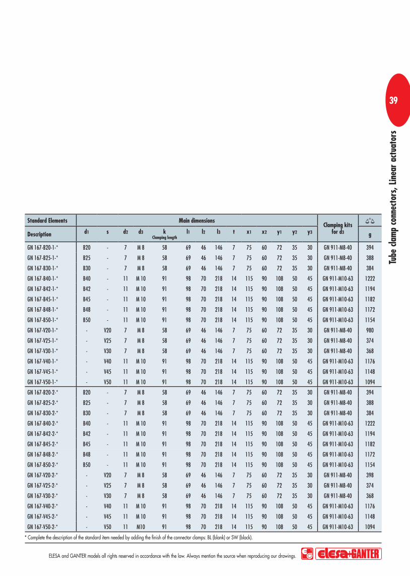
Features and applicationsThe clamping bores of the wide base plate connector clamps GN 167 are machined and designed for construction tubings GN 990 or DIN 2391, DIN 2395 and DIN 2462 respectively.Accessories- Tubings GN 990 (see page 103ff.). - Clamping kits GN 911(clamping handles GN 300.1 with distance bushing)
see page 110.
MaterialAluminium.Finish- Version SW: RAL 9005 black colour, matte finish, epoxy resin coating. - Version BL: blank, matte shot-blasted.Clamping screws- Identification no. 1: with two clamping screws DIN 912 and nuts
DIN 985, zinc-plated.- Identification no. 2: with two AISI 304 stainless steel-clamping screws
DIN 912 and nuts DIN 985.AssemblyThe standard clamping bolts are socket cap screws DIN 912, supplied assembled. They can be replaced by clamping kits GN 911 (description see table of dimensions).
Wide base plate connector clamps
GN 167
Tube
cla
mp
conn
ecto
rs, L
inea
r ac
tuat
ors
ELESA and GANTER models all rights reserved in accordance with the law. Always mention the source when reproducing our drawings.
39
Standard Elements Main dimensionsClamping kits
for d3Description d1 s d2 d3 k Clamping length
l1 l2 l3 t x1 x2 y1 y2 y3 g
GN 167-B20-1-* B20 - 7 M 8 58 69 46 146 7 75 60 72 35 30 GN 911-M8-40 394
GN 167-B25-1-* B25 - 7 M 8 58 69 46 146 7 75 60 72 35 30 GN 911-M8-40 388
GN 167-B30-1-* B30 - 7 M 8 58 69 46 146 7 75 60 72 35 30 GN 911-M8-40 384
GN 167-B40-1-* B40 - 11 M 10 91 98 70 218 14 115 90 108 50 45 GN 911-M10-63 1222
GN 167-B42-1-* B42 - 11 M 10 91 98 70 218 14 115 90 108 50 45 GN 911-M10-63 1194
GN 167-B45-1-* B45 - 11 M 10 91 98 70 218 14 115 90 108 50 45 GN 911-M10-63 1182
GN 167-B48-1-* B48 - 11 M 10 91 98 70 218 14 115 90 108 50 45 GN 911-M10-63 1172
GN 167-B50-1-* B50 - 11 M 10 91 98 70 218 14 115 90 108 50 45 GN 911-M10-63 1154
GN 167-V20-1-* - V20 7 M 8 58 69 46 146 7 75 60 72 35 30 GN 911-M8-40 980
GN 167-V25-1-* - V25 7 M 8 58 69 46 146 7 75 60 72 35 30 GN 911-M8-40 374
GN 167-V30-1-* - V30 7 M 8 58 69 46 146 7 75 60 72 35 30 GN 911-M8-40 368
GN 167-V40-1-* - V40 11 M 10 91 98 70 218 14 115 90 108 50 45 GN 911-M10-63 1176
GN 167-V45-1-* - V45 11 M 10 91 98 70 218 14 115 90 108 50 45 GN 911-M10-63 1148
GN 167-V50-1-* - V50 11 M 10 91 98 70 218 14 115 90 108 50 45 GN 911-M10-63 1094
GN 167-B20-2-* B20 - 7 M 8 58 69 46 146 7 75 60 72 35 30 GN 911-M8-40 394
GN 167-B25-2-* B25 - 7 M 8 58 69 46 146 7 75 60 72 35 30 GN 911-M8-40 388
GN 167-B30-2-* B30 - 7 M 8 58 69 46 146 7 75 60 72 35 30 GN 911-M8-40 384
GN 167-B40-2-* B40 - 11 M 10 91 98 70 218 14 115 90 108 50 45 GN 911-M10-63 1222
GN 167-B42-2-* B42 - 11 M 10 91 98 70 218 14 115 90 108 50 45 GN 911-M10-63 1194
GN 167-B45-2-* B45 - 11 M 10 91 98 70 218 14 115 90 108 50 45 GN 911-M10-63 1182
GN 167-B48-2-* B48 - 11 M 10 91 98 70 218 14 115 90 108 50 45 GN 911-M10-63 1172
GN 167-B50-2-* B50 - 11 M 10 91 98 70 218 14 115 90 108 50 45 GN 911-M10-63 1154
GN 167-V20-2-* - V20 7 M 8 58 69 46 146 7 75 60 72 35 30 GN 911-M8-40 398
GN 167-V25-2-* - V25 7 M 8 58 69 46 146 7 75 60 72 35 30 GN 911-M8-40 374
GN 167-V30-2-* - V30 7 M 8 58 69 46 146 7 75 60 72 35 30 GN 911-M8-40 368
GN 167-V40-2-* - V40 11 M 10 91 98 70 218 14 115 90 108 50 45 GN 911-M10-63 1176
GN 167-V45-2-* - V45 11 M 10 91 98 70 218 14 115 90 108 50 45 GN 911-M10-63 1148
GN 167-V50-2-* - V50 11 M10 91 98 70 218 14 115 90 108 50 45 GN 911-M10-63 1094
* Complete the description of the standard item needed by adding the finish of the connector clamps: BL (blank) or SW (black).

1
Tube
cla
mp
conn
ecto
rs, L
inea
r ac
tuat
ors
ELESA and GANTER models all rights reserved in accordance with the law. Always mention the source when reproducing our drawings.
4040
Features and applicationsThe clamping bores of the flanged base plate connector clamps GN 171 are not machined and designed for construction tubings GN 990 or DIN 2391, DIN 2395 and DIN 2462 respectively.Accessories- Tubings GN 990 (see page 103ff.) . - Clamping kits GN 911(clamping handles GN 300.1 with distance bushing)
see page 110.
MaterialAluminium.Finish- Version SW: RAL 9005 black colour, matte finish, epoxy resin coating. - Version BL: blank, matte shot-blasted.Clamping screws- Identification no. 1: with two clamping screw DIN 912 and nuts
DIN 985, zinc plated.- Identification no. 2: with two AISI 304 stainless steel-clamping screw
DIN 912 and nuts DIN 985.AssemblyThe standard clamping bolts are socket cap screws DIN 912, supplied assembled. They can be replaced by clamping kits GN 911 (description see table of dimensions).
Flanged base plate connector clamps
GN 171

Tube
cla
mp
conn
ecto
rs, L
inea
r ac
tuat
ors
ELESA and GANTER models all rights reserved in accordance with the law. Always mention the source when reproducing our drawings.
41
Standard Elements Main dimensionsClamping kits
for d3Description d1 s d2 d3 k Clamping length
l1 l2 l3 l4 t x1 x2 y1 y2 y3 y4 g
GN 171-B20-1-* B20 - 7 M8 58 69 53 103 30 7 75 60 72 35 30 50 GN 911-M8-45 344
GN 171-B25-1-* B25 - 7 M8 58 69 53 103 30 7 75 60 72 35 30 50 GN 911-M8-45 337
GN 171-B30-1-* B30 - 7 M8 58 69 53 103 30 7 75 60 72 35 30 50 GN 911-M8-45 330
GN 171-B40-1-* B40 - 11 M10 91 98 82 156 47 14 115 90 108 50 45 76 GN 911-M10-70 1014
GN 171-B42-1-* B42 - 11 M10 91 98 82 156 47 14 115 90 108 50 45 76 GN 911-M10-70 995
GN 171-B45-1-* B45 - 11 M10 91 98 82 156 47 14 115 90 108 50 45 76 GN 911-M10-70 982
GN 171-B48-1-* B48 - 11 M10 91 98 82 156 47 14 115 90 108 50 45 76 GN 911-M10-70 973
GN 171-B50-1-* B50 - 11 M10 91 98 82 156 47 14 115 90 108 50 45 76 GN 911-M10-70 959
GN 171-V20-1-* - V20 7 M8 58 69 53 103 30 7 75 60 72 35 30 50 GN 911-M8-45 343
GN 171-V25-1-* - V25 7 M8 58 69 53 103 30 7 75 60 72 35 30 50 GN 911-M8-45 326
GN 171-V30-1-* - V30 7 M8 58 69 53 103 30 7 75 60 72 35 30 50 GN 911-M8-45 316
GN 171-V40-1-* - V40 11 M10 91 98 82 156 47 14 115 90 108 50 45 76 GN 911-M10-70 981
GN 171-V45-1-* - V45 11 M10 91 98 82 156 47 14 115 90 108 50 45 76 GN 911-M10-70 958
GN 171-V50-1-* - V50 11 M10 91 98 82 156 47 14 115 90 108 50 45 76 GN 911-M10-70 918
GN 171-B20-2-* B20 - 7 M8 58 69 53 103 30 7 75 60 72 35 30 50 GN 911-M8-45 344
GN 171-B25-2-* B25 - 7 M8 58 69 53 103 30 7 75 60 72 35 30 50 GN 911-M8-45 337
GN 171-B30-2-* B30 - 7 M8 58 69 53 103 30 7 75 60 72 35 30 50 GN 911-M8-45 330
GN 171-B40-2-* B40 - 11 M10 91 98 82 156 47 14 115 90 108 50 45 76 GN 911-M10-70 1014
GN 171-B42-2-* B42 - 11 M10 91 98 82 156 47 14 115 90 108 50 45 76 GN 911-M10-70 995
GN 171-B45-2-* B45 - 11 M10 91 98 82 156 47 14 115 90 108 50 45 76 GN 911-M10-70 982
GN 171-B48-2-* B48 - 11 M10 91 98 82 156 47 14 115 90 108 50 45 76 GN 911-M10-70 973
GN 171-B50-2-* B50 - 11 M10 91 98 82 156 47 14 115 90 108 50 45 76 GN 911-M10-70 959
GN 171-V20-2-* - V20 7 M8 58 69 53 103 30 7 75 60 72 35 30 50 GN 911-M8-45 343
GN 171-V25-2-* - V25 7 M8 58 69 53 103 30 7 75 60 72 35 30 50 GN 911-M8-45 326
GN 171-V30-2-* - V30 7 M8 58 69 53 103 30 7 75 60 72 35 30 50 GN 911-M8-45 316
GN 171-V40-2-* - V40 11 M10 91 98 82 156 47 14 115 90 108 50 45 76 GN 911-M10-70 981
GN 171-V45-2-* - V45 11 M10 91 98 82 156 47 14 115 90 108 50 45 76 GN 911-M10-70 958
GN 171-V50-2-* - V50 11 M10 91 98 82 156 47 14 115 90 108 50 45 76 GN 911-M10-70 918
* Complete the description of the standard item needed by adding the finish of the connector clamps: BL (blank) or SW (black).

1
Tube
cla
mp
conn
ecto
rs, L
inea
r ac
tuat
ors
ELESA and GANTER models all rights reserved in accordance with the law. Always mention the source when reproducing our drawings.
4242
Base plate connector clamps GN 162 (see page 30) Stainless Steel-Base plate connector clamps GN 162 (see page 31) Base plate connector clamps GN 163 (see page 32) Base plate connector clamps GN 165 (see page 34) Off-set base plate connector clamps GN 166 (see page 36) Wide base plate connector clamps GN 167 (see page 38) Flanged base plate connector clamps GN 171 (see page 40)

Tube
cla
mp
conn
ecto
rs, L
inea
r ac
tuat
ors
ELESA and GANTER models all rights reserved in accordance with the law. Always mention the source when reproducing our drawings.
43
T-angle connector clamps GN 191 (see page 44) Stainless Steel-T-angle connector clamps GN 191 (see page 45) T-angle connector clamps GN 192 (see page 46) T-angle connector clamps GN 193 (see page 48) T-angle connector clamps GN 194 (see page 51) T-angle connector clamps GN 195 (see page 54)

1
Tube
cla
mp
conn
ecto
rs, L
inea
r ac
tuat
ors
ELESA and GANTER models all rights reserved in accordance with the law. Always mention the source when reproducing our drawings.
4444
Features and applicationsThe clamping bores of the T-angle connector clamps GN 191 are machined and designed for tubings GN 990 or DIN 2391, DIN 2395 and DIN 2462 respectively.Accessories- Tubings GN 990 (see page 103ff.). - Clamping kits GN 911(clamping handles GN 300.1 with distance bushing)
see page 110.Special executions on request (For sufficient quantities)Different combinations of bores d1/d2.
MaterialAluminium.Finish- Version SW: RAL 9005 black colour, matte finish, epoxy resin coating. - Version BL: blank, matte shot-blasted.Clamping screws- Identification no. 1: with two clamping screws DIN 912 and nuts
DIN 985, zinc-plated.- Identification no. 2: with two AISI 304 stainless steel-clamping screws
DIN 912 and nuts DIN 985. AssemblyThe standard clamping bolts are socket cap screws DIN 912, supplied assembled. They can be replaced by clamping kits GN 911 (description see table of dimensions).
T-angle connector clamps
GN 191
Standard Elements Main dimensionsClamping kits
for d3Description d1 d2 d3 k Clamping length
l1 l2 m g
GN 191-B10-B10-1-* B10 B10 M6 25 61 34.5 39 GN 911-M6-22 97
GN 191-B12-B12-1-* B12 B12 M6 25 61 34.5 39 GN 911-M6-22 93
GN 191-B14-B14-1-* B14 B14 M6 25 61 34.5 39 GN 911-M6-22 89
GN 191-B15-B15-1-* B15 B15 M6 25 61 34.5 39 GN 911-M6-22 86
GN 191-B16-B16-1-* B16 B16 M6 25 61 34.5 39 GN 911-M6-22 84
GN 191-B18-B18-1-* B18 B18 M6 25 61 34.5 39 GN 911-M6-22 81
GN 191-B10-B10-2-* B10 B10 M6 25 61 34.5 39 GN 911-M6-22 97
GN 191-B12-B12-2-* B12 B12 M6 25 61 34.5 39 GN 911-M6-22 93
GN 191-B14-B14-2-* B14 B14 M6 25 61 34.5 39 GN 911-M6-22 89
GN 191-B15-B15-2-* B15 B15 M6 25 61 34.5 39 GN 911-M6-22 86
GN 191-B16-B16-2-* B16 B16 M6 25 61 34.5 39 GN 911-M6-22 84
GN 191-B18-B18-2-* B18 B18 M6 25 61 34.5 39 GN 911-M6-22 81
* Complete the description of the standard item needed by adding the finish of the connector clamps: BL (blank) or SW (black).

Tube
cla
mp
conn
ecto
rs, L
inea
r ac
tuat
ors
ELESA and GANTER models all rights reserved in accordance with the law. Always mention the source when reproducing our drawings.
45
Standard Elements Main dimensionsClamping kits
for d3Description d1 d2 d3 k Clamping length
l1 l2 m g
GN 191-B12-B12-2-NI B12 B12 M6 25 61 34.5 39 GN 911-M6-22 240
GN 191-B14-B14-2-NI B14 B14 M6 25 61 34.5 39 GN 911-M6-22 220
GN 191-B16-B16-2-NI B16 B16 M6 25 61 34.5 39 GN 911-M6-22 200
GN 191-B18-B18-2-NI B18 B18 M6 25 61 34.5 39 GN 911-M6-22 175
Features and applicationsThe clamping bores of the T-angle connector clamps GN 191-NI are ma-chined and designed for tubings GN 990 or DIN 2391, DIN 2395 and DIN 2462 respectively.Accessories- Tubings GN 990 (see page 103ff.). - Clamping kits GN 911(clamping handles GN 300.1 with distance bushing)
see page 110.Special executions on request (For sufficient quantities) Different combinations of bores d1/d2.
MaterialAISI CF-8 stainless steel NI, matte polished.Clamping screwsIdentification no. 2: with two AISI 304 stainless steel-clamping screws DIN 912 and nuts DIN 985.AssemblyThe standard clamping bolts are socket cap screws DIN 912, supplied assembled. They can be replaced by clamping kits GN 911 (description see table of dimensions).
T-angle connector clamps
GN 191-NI

1
Tube
cla
mp
conn
ecto
rs, L
inea
r ac
tuat
ors
ELESA and GANTER models all rights reserved in accordance with the law. Always mention the source when reproducing our drawings.
4646
Features and applicationsThe clamping bores of the T-angle connector clamps GN 192 are machined and designed for tubings GN 990 or DIN 2391, DIN 2395 and DIN 2462 respectively.Accessories- Tubings GN 990 (see page 103ff.). - Clamping kits GN 911(clamping handles GN 300.1 with distance bushing)
see page 110.Special executions on request (For sufficient quantities)Different combinations of bores d1/d2.
MaterialAluminium.Finish- Version SW: RAL 9005 black colour, matte finish, epoxy resin coating. - Version BL: blank, matte shot-blasted.Clamping screws- Identification no. 1: with two clamping screws DIN 912 and nuts
DIN 985, zinc-plated.- Identification no. 2: with two AISI 304 stainless steel-clamping screws
DIN 912 and nuts DIN 985.AssemblyThe standard clamping bolts are socket cap screws DIN 912, supplied assembled. They can be replaced by clamping kits GN 911 (description see table of dimensions).
T-angle connector clamps
GN 192

Tube
cla
mp
conn
ecto
rs, L
inea
r ac
tuat
ors
ELESA and GANTER models all rights reserved in accordance with the law. Always mention the source when reproducing our drawings.
47
Standard Elements Main dimensions Clamping kitsfor d3Description d1 d2 k1 d3 k2 l1 l2 m g
GN 192-B20-B20-40-1-* B20 B20 40 M8 42.5 92 52 60 GN 911-M8-32 267
GN 192-B25-B25-40-1-* B25 B25 40 M8 42.5 92 52 60 GN 911-M8-32 231
GN 192-B30-B30-40-1-* B30 B30 40 M8 42.5 92 52 60 GN 911-M8-32 186
GN 192-B30-B30-56-1-* B30 B30 56 M10 62 129 69 88 GN 911-M10-40 661
GN 192-B32-B32-56-1-* B32 B32 56 M10 62 129 69 88 GN 911-M10-40 619
GN 192-B35-B35-56-1-* B35 B35 56 M10 62 129 69 88 GN 911-M10-40 570
GN 192-B40-B40-56-1-* B40 B40 56 M10 62 129 69 88 GN 911-M10-40 481
GN 192-B40-B40-65-1-* B40 B40 65 M10 75 148 77.5 103 GN 911-M10-55 922
GN 192-B42-B42-65-1-* B42 B42 65 M10 75 148 77.5 103 GN 911-M10-55 889
GN 192-B45-B45-65-1-* B45 B45 65 M10 75 148 77.5 103 GN 911-M10-55 874
GN 192-B48-B48-65-1-* B48 B48 65 M10 75 148 77.5 103 GN 911-M10-55 732
GN 192-B50-B50-65-1-* B50 B50 65 M10 75 148 77.5 103 GN 911-M10-55 676
GN 192-B50-B50-80-1-* B50 B50 80 M10 80 177 92 125 GN 911-M10-55 1660
GN 192-B55-B55-80-1-* B55 B55 80 M10 80 177 92 125 GN 911-M10-55 1460
GN 192-B60-B60-80-1-* B60 B60 80 M10 80 177 92 125 GN 911-M10-55 1260
GN 192-B20-B20-40-2-* B20 B20 40 M8 42.5 92 52 60 GN 911-M8-32 267
GN 192-B25-B25-40-2-* B25 B25 40 M8 42.5 92 52 60 GN 911-M8-32 231
GN 192-B30-B30-40-2-* B30 B30 40 M8 42.5 92 52 60 GN 911-M8-32 186
GN 192-B30-B30-56-2-* B30 B30 56 M10 62 129 69 88 GN 911-M10-40 661
GN 192-B32-B32-56-2-* B32 B32 56 M10 62 129 69 88 GN 911-M10-40 619
GN 192-B35-B35-56-2-* B35 B35 56 M10 62 129 69 88 GN 911-M10-40 570
GN 192-B40-B40-56-2-* B40 B40 56 M10 62 129 69 88 GN 911-M10-40 481
GN 192-B40-B40-65-2-* B40 B40 65 M10 75 148 11.5 103 GN 911-M10-55 922
GN 192-B42-B42-65-2-* B42 B42 65 M10 75 148 77.5 103 GN 911-M10-55 889
GN 192-B45-B45-65-2-* B45 B45 65 M10 75 148 77.5 103 GN 911-M10-55 874
GN 192-B48-B48-65-2-* B48 B48 65 M10 75 148 77.5 103 GN 911-M10-55 732
GN 192-B50-B50-65-2-* B50 B50 65 M10 75 148 77.5 103 GN 911-M10-55 676
GN 192-B50-B50-80-2-* B50 B50 80 M10 80 177 92 125 GN 911-M10-55 1660
GN 192-B55-B55-80-2-* B55 B55 80 M10 80 177 92 125 GN 911-M10-55 1460
GN 192-B60-B60-80-2-* B60 B60 80 M10 80 177 92 125 GN 911-M10-55 1260
* Complete the description of the standard item needed by adding the finish of the connector clamps: BL (blank) or SW (black).

1
Tube
cla
mp
conn
ecto
rs, L
inea
r ac
tuat
ors
ELESA and GANTER models all rights reserved in accordance with the law. Always mention the source when reproducing our drawings.
4848
Features and applicationsThe clamping bores of the T-angle connector clamps GN 193 are not machined and designed for construction tubings GN 990 or DIN 2391, DIN 2395 and DIN 2462 respectively. Within the same nominal size the T-angle connector clamp bores can be sup-plied with the bores d1 and d2 and square bores s1 and s2 i.e. in combination with d1 and s2 or s1 and d2.Accessories- Tubings GN 990 (see page 103ff.). - Clamping kits GN 911(clamping handles GN 300.1 with distance bushing)
see page 110.
MaterialAluminium.Finish- Version SW: RAL 9005 black colour, matte finish, epoxy resin coating. - Version BL: blank, matte shot-blasted.Clamping screws- Identification no. 1: with two clamping screws DIN 912 and nuts
DIN 985, zinc-plated.- Identification no. 2: with two AISI 304 stainless steel-clamping screws
DIN 912 and nuts DIN 985.AssemblyThe standard clamping bolts are socket cap screws DIN 912, supplied assembled. They can be replaced by clamping kits GN 911 (description see table of dimensions).
T-angle connector clamps
GN 193

Tube
cla
mp
conn
ecto
rs, L
inea
r ac
tuat
ors
ELESA and GANTER models all rights reserved in accordance with the law. Always mention the source when reproducing our drawings.
49Standard Elements Main dimensions
Clamping kitsfor d3Description d1
Bore Bs1
Square Vd2
Bore Bs2
Square Vk
Clamping lengthd3 l1 l2 l3 m g
GN 193-B20-B20-50-1-* B20 - B20 - 50 M8 120 68 46 85 GN 911-M8-40 446
GN 193-B25-B25-50-1-* B25 - B25 - 50 M8 120 68 46 85 GN 911-M8-40 436
GN 193-B30-B30-50-1-* B30 - B30 - 50 M8 120 68 46 85 GN 911-M8-40 422
GN 193-B30-B30-60-1-* B30 - B30 - 60 M8 141 79 59 101.5 GN 911-M8-55 742
GN 193-B32-B32-60-1-* B32 - B32 - 60 M8 141 79 59 101.5 GN 911-M8-55 730
GN 193-B35-B35-60-1-* B35 - B35 - 60 M8 141 79 59 101.5 GN 911-M8-55 696
GN 193-B40-B40-60-1-* B40 - B40 - 60 M8 141 79 59 101.5 GN 911-M8-55 684
GN 193-B40-B40-76-1-* B40 - B40 - 76 M10 176 98 70 126 GN 911-M10-63 1198
GN 193-B42-B42-76-1-* B42 - B42 - 76 M10 176 98 70 126 GN 911-M10-63 1188
GN 193-B45-B45-76-1-* B45 - B45 - 76 M10 176 98 70 126 GN 911-M10-63 1164
GN 193-B48-B48-76-1-* B48 - B48 - 76 M10 176 98 70 126 GN 911-M10-63 1134
GN 193-B50-B50-76-1-* B50 - B50 - 76 M10 176 98 70 126 GN 911-M10-63 1104
GN 193-B20-V20-50-1-* B20 - - V20 50 M8 120 68 46 85 GN 911-M8-40 476
GN 193-B25-V25-50-1-* B25 - - V25 50 M8 120 68 46 85 GN 911-M8-40 452
GN 193-B30-V30-50-1-* B30 - - V30 50 M8 120 68 46 85 GN 911-M8-40 428
GN 193-B30-V30-60-1-* B30 - - V30 60 M8 141 79 59 101.5 GN 911-M8-55 728
GN 193-B35-V35-60-1-* B35 - - V35 60 M8 141 79 59 101.5 GN 911-M8-55 692
GN 193-B40-V40-60-1-* B40 - - V40 60 M8 141 79 59 101.5 GN 911-M8-55 638
GN 193-B40-V40-76-1-* B40 - - V40 76 M10 176 98 70 126 GN 911-M10-63 1118
GN 193-B45-V45-76-1-* B45 - - V45 76 M10 176 98 70 126 GN 911-M10-63 1138
GN 193-B50-V50-76-1-* B50 - - V50 76 M10 176 98 70 126 GN 911-M10-63 1086
GN 193-V20-V20-50-1-* - V20 - V20 50 M8 120 68 46 85 GN 911-M8-40 430
GN 193-V25-V25-50-1-* - V25 - V25 50 M8 120 68 46 85 GN 911-M8-40 420
GN 193-V30-V30-50-1-* - V30 - V30 50 M8 120 68 46 85 GN 911-M8-40 410
GN 193-V30-V30-60-1-* - V30 - V30 60 M8 141 79 59 101.5 GN 911-M8-55 728
GN 193-V35-V35-60-1-* - V35 - V35 60 M8 141 79 59 101.5 GN 911-M8-55 692
GN 193-V40-V40-60-1-* - V40 - V40 60 M8 141 79 59 101.5 GN 911-M8-55 638
GN 193-V40-V40-76-1-* - V40 - V40 76 M10 176 98 70 126 GN 911-M10-63 1158
GN 193-V45-V45-76-1-* - V45 - V45 76 M10 176 98 70 126 GN 911-M10-63 1104
GN 193-V50-V50-76-1-* - V50 - V50 76 M10 176 98 70 126 GN 911-M10-63 1054
GN 193-V20-B20-50-1-* - V20 B20 - 50 M8 120 68 46 85 GN 911-M8-40 450
GN 193-V25-B25-50-1-* - V25 B25 - 50 M8 120 68 46 85 GN 911-M8-40 430
GN 193-V30-B30-50-1-* - V30 B30 - 50 M8 120 68 46 85 GN 911-M8-40 410
GN 193-V30-B30-60-1-* - V30 B30 - 60 M8 141 79 59 101.5 GN 911-M8-55 728
GN 193-V35-B35-60-1-* - V35 B35 - 60 M8 141 79 59 101.5 GN 911-M8-55 692
GN 193-V40-B40-60-1-* - V40 B40 - 60 M8 141 79 59 101.5 GN 911-M8-55 638
GN 193-V40-B40-76-1-* - V40 B40 - 76 M10 176 98 70 126 GN 911-M10-63 1150
GN 193-V45-B45-76-1-* - V45 B45 - 76 M10 176 98 70 126 GN 911-M10-63 1100
GN 193-V50-B50-76-1-* - V50 B50 - 76 M10 176 98 70 126 GN 911-M10-63 1070
* Complete the description of the standard item needed by adding the finish of the connector clamps: BL (blank) or SW (black).

1
Tube
cla
mp
conn
ecto
rs, L
inea
r ac
tuat
ors
ELESA and GANTER models all rights reserved in accordance with the law. Always mention the source when reproducing our drawings.
5050
Standard Elements Main dimensionsClamping kits
for d3Description d1 Bore B
s1 Square V
d2 Bore B
s2 Square V
k Clamping length
d3 l1 l2 l3 m g
GN 193-B20-B20-50-2-* B20 - B20 - 50 M8 120 68 46 85 GN 911-M8-40 446
GN 193-B25-B25-50-2-* B25 - B25 - 50 M8 120 68 46 85 GN 911-M8-40 436
GN 193-B30-B30-50-2-* B30 - B30 - 50 M8 120 68 46 85 GN 911-M8-40 422
GN 193-B30-B30-60-2-* B30 - B30 - 60 M8 141 79 59 101.5 GN 911-M8-55 742
GN 193-B32-B32-60-2-* B32 - B32 - 60 M8 141 79 59 101.5 GN 911-M8-55 730
GN 193-B35-B35-60-2-* B35 - B35 - 60 M8 141 79 59 101.5 GN 911-M8-55 696
GN 193-B40-B40-60-2-* B40 - B40 - 60 M8 141 79 59 101.5 GN 911-M8-55 684
GN 193-B40-B40-76-2-* B40 - B40 - 76 M10 176 98 70 126 GN 911-M10-63 1198
GN 193-B42-B42-76-2-* B42 - B42 - 76 M10 176 98 70 126 GN 911-M10-63 1188
GN 193-B45-B45-76-2-* B45 - B45 - 76 M10 176 98 70 126 GN 911-M10-63 1164
GN 193-B48-B48-76-2-* B48 - B48 - 76 M10 176 98 70 126 GN 911-M10-63 1134
GN 193-B50-B50-76-2-* B50 - B50 - 76 M10 176 98 70 126 GN 911-M10-63 1104
GN 193-B20-V20-50-2-* B20 - - V20 50 M8 120 68 46 85 GN 911-M8-40 476
GN 193-B25-V25-50-2-* B25 - - V25 50 M8 120 68 46 85 GN 911-M8-40 452
GN 193-B30-V30-50-2-* B30 - - V30 50 M8 120 68 46 85 GN 911-M8-40 540
GN 193-B30-V30-60-2-* B30 - - V30 60 M8 141 79 59 101.5 GN 911-M10-55 728
GN 193-B35-V35-60-2-* B35 - - V35 60 M8 141 79 59 101.5 GN 911-M10-55 696
GN 193-B40-V40-60-2-* B40 - - V40 60 M8 141 79 59 101.5 GN 911-M10-55 638
GN 193-B40-V40-76-2-* B40 - - V40 76 M10 176 98 70 126 GN 911-M10-63 1118
GN 193-B45-V45-76-2-* B45 - - V45 76 M10 176 98 70 126 GN 911-M10-63 1138
GN 193-B50-V50-76-2-* B50 - - V50 76 M10 176 98 70 126 GN 911-M10-63 1086
GN 193-V20-V20-50-2-* - V20 - V20 50 M8 120 68 46 85 GN 911-M8-40 430
GN 193-V25-V25-50-2-* - V25 - V25 50 M8 120 68 46 85 GN 911-M8-40 420
GN 193-V30-V30-50-2-* - V30 - V30 50 M8 120 68 46 85 GN 911-M8-40 410
GN 193-V30-V30-60-2-* - V30 - V30 60 M8 141 79 59 101.5 GN 911-M8-55 728
GN 193-V35-V35-60-2-* - V35 - V35 60 M8 141 79 59 101.5 GN 911-M8-55 692
GN 193-V40-V40-60-2-* - V40 - V40 60 M8 141 79 59 101.5 GN 911-M8-55 638
GN 193-V40-V40-76-2-* - V40 - V40 76 M10 176 98 70 126 GN 911-M10-63 1158
GN 193-V45-V45-76-2-* - V45 - V45 76 M10 176 98 70 126 GN 911-M10-63 1104
GN 193-V50-V50-76-2-* - V50 - V50 76 M10 176 98 70 126 GN 911-M10-63 1054
GN 193-V20-B20-50-2-* - V20 B20 - 50 M8 120 68 46 85 GN 911-M8-40 450
GN 193-V25-B25-50-2-* - V25 B25 - 50 M8 120 68 46 85 GN 911-M8-40 430
GN 193-V30-B30-50-2-* - V30 B30 - 50 M8 120 68 46 85 GN 911-M8-40 410
GN 193-V30-B30-60-2-* - V30 B30 - 60 M8 141 79 59 101.5 GN 911-M8-55 728
GN 193-V35-B35-60-2-* - V35 B35 - 60 M8 141 79 59 101.5 GN 911-M8-55 692
GN 193-V40-B40-60-2-* - V40 B40 - 60 M8 141 79 59 101.5 GN 911-M8-55 638
GN 193-V40-B40-76-2-* - V40 B40 - 76 M10 176 98 70 126 GN 911-M10-63 1150
GN 193-V45-B45-76-2-* - V45 B45 - 76 M10 176 98 70 126 GN 911-M10-63 1100
GN 193-V50-B50-76-2-* - V50 B50 - 76 M10 176 98 70 126 GN 911-M10-63 1070
* Complete the description of the standard item needed by adding the finish of the connector clamps: BL (blank) or SW (black).

Tube
cla
mp
conn
ecto
rs, L
inea
r ac
tuat
ors
ELESA and GANTER models all rights reserved in accordance with the law. Always mention the source when reproducing our drawings.
51
Features and applicationsThe clamping bores of the T-angle connector clamps GN 194 are not machined and designed for construction tubings GN 990 or DIN 2391, DIN 2395 and DIN 2462 respectively. Within the same nominal size the T-angle connector clamp bores can be sup-plied with the bores d1 and d2 and square bores s1 and s2 i.e. in combination with d1 and s2 or s1 and d2.Accessories- Tubings GN 990 (see page 103ff.). - Clamping kits GN 911 (clamping handles GN 300.1 with distance bushing) see page 110.
MaterialAluminium.Finish- Version SW: RAL 9005 black colour, matte finish, epoxy resin coating. - Version BL: blank, matte shot-blasted.Clamping screws- Identification no. 1: with two clamping screws DIN 912 and nuts
DIN 985, zinc-plated.- Identification no. 2: with two AISI 304 stainless steel-clamping screws
DIN 912 and nuts DIN 985.AssemblyThe standard clamping bolts are socket cap screws DIN 912, supplied assembled. They can be replaced by clamping kits GN 911 (description see table of dimensions).
T-angle connector clamps
GN 194

1
Tube
cla
mp
conn
ecto
rs, L
inea
r ac
tuat
ors
ELESA and GANTER models all rights reserved in accordance with the law. Always mention the source when reproducing our drawings.
5252
Standard Elements Main dimensionsClamping kits
for d3Description d1 s1 d2 s2 k Clamping length
d3 l1 l2 l3 m g
GN 194-B20-B20-50-1-* B20 - B20 - 50 M8 120 68 46 85 GN 911-M8-40 423
GN 194-B25-B25-50-1-* B25 - B25 - 50 M8 120 68 46 85 GN 911-M8-40 412
GN 194-B30-B30-50-1-* B30 - B30 - 50 M8 120 68 46 85 GN 911-M8-40 399
GN 194-B30-B30-60-1-* B30 - B30 - 60 M8 141 79 59 101.5 GN 911-M8-55 758
GN 194-B32-B32-60-1-* B32 - B32 - 60 M8 141 79 59 101.5 GN 911-M8-55 734
GN 194-B35-B35-60-1-* B35 - B35 - 60 M8 141 79 59 101.5 GN 911-M8-55 704
GN 194-B40-B40-60-1-* B40 - B40 - 60 M8 141 79 59 101.5 GN 911-M8-55 688
GN 194-B40-B40-76-1-* B40 - B40 - 76 M10 176 98 70 126 GN 911-M10-63 1123
GN 194-B42-B42-76-1-* B42 - B42 - 76 M10 176 98 70 126 GN 911-M10-63 1100
GN 194-B45-B45-76-1-* B45 - B45 - 76 M10 176 98 70 126 GN 911-M10-63 1080
GN 194-B48-B48-76-1-* B48 - B48 - 76 M10 176 98 70 126 GN 911-M10-63 1055
GN 194-B50-B50-76-1-* B50 - B50 - 76 M10 176 98 70 126 GN 911-M10-63 1028
GN 194-B20-V20-50-1-* B20 - - V20 50 M8 120 68 46 85 GN 911-M8-40 423
GN 194-B25-V25-50-1-* B25 - - V25 50 M8 120 68 46 85 GN 911-M8-40 395
GN 194-B30-V30-50-1-* B30 - - V30 50 M8 120 68 46 85 GN 911-M8-40 342
GN 194-B30-V30-60-1-* B30 - - V30 60 M8 141 79 59 101.5 GN 911-M8-55 746
GN 194-B35-V35-60-1-* B35 - - V35 60 M8 141 79 59 101.5 GN 911-M8-55 713
GN 194-B40-V40-60-1-* B40 - - V40 60 M8 141 79 59 101.5 GN 911-M8-55 700
GN 194-B40-V40-76-1-* B40 - - V40 76 M10 176 98 70 126 GN 911-M10-63 1100
GN 194-B45-V45-76-1-* B45 - - V45 76 M10 176 98 70 126 GN 911-M10-63 1065
GN 194-B50-V50-76-1-* B50 - - V50 76 M10 176 98 70 126 GN 911-M10-63 1015
GN 194-V20-V20-50-1-* - V20 - V20 50 M8 120 68 46 85 GN 911-M8-40 419
GN 194-V25-V25-50-1-* - V25 - V25 50 M8 120 68 46 85 GN 911-M8-40 398
GN 194-V30-V30-50-1-* - V30 - V30 50 M8 120 68 46 85 GN 911-M8-40 376
GN 194-V30-V30-60-1-* - V30 - V30 60 M8 141 79 59 101.5 GN 911-M8-55 734
GN 194-V35-V35-60-1-* - V35 - V35 60 M8 141 79 59 101.5 GN 911-M8-55 692
GN 194-V40-V40-60-1-* - V40 - V40 60 M8 141 79 59 101.5 GN 911-M8-55 628
GN 194-V40-V40-76-1-* - V40 - V40 76 M10 176 98 70 126 GN 911-M10-63 1079
GN 194-V45-V45-76-1-* - V45 - V45 76 M10 176 98 70 126 GN 911-M10-63 1036
GN 194-V50-V50-76-1-* - V50 - V50 76 M10 176 98 70 126 GN 911-M10-63 975
GN 194-V20-B20-50-1-* - V20 B20 - 50 M8 120 68 46 85 GN 911-M8-40 436
GN 194-V25-B25-50-1-* - V25 B25 - 50 M8 120 68 46 85 GN 911-M8-40 417
GN 194-V30-B30-50-1-* - V30 B30 - 50 M8 120 68 46 85 GN 911-M8-40 397
GN 194-V30-B30-60-1-* - V30 B30 - 60 M8 141 79 59 101.5 GN 911-M8-55 746
GN 194-V35-B35-60-1-* - V35 B35 - 60 M8 141 79 59 101.5 GN 911-M8-55 713
GN 194-V40-B40-60-1-* - V40 B40 - 60 M8 141 79 59 101.5 GN 911-M8-55 658
GN 194-V40-B40-76-1-* - V40 B40 - 76 M10 176 98 70 126 GN 911-M10-63 1100
GN 194-V45-B45-76-1-* - V45 B45 - 76 M10 176 98 70 126 GN 911-M10-63 1060
GN 194-V50-B50-76-1-* - V50 B50 - 76 M10 176 98 70 126 GN 911-M10-63 1005
* Complete the description of the standard item needed by adding the finish of the connector clamps: BL (blank) or SW (black).

Tube
cla
mp
conn
ecto
rs, L
inea
r ac
tuat
ors
ELESA and GANTER models all rights reserved in accordance with the law. Always mention the source when reproducing our drawings.
53Standard Elements Main dimensions
Clamping kitsfor d3Description d1 s1 d2 s2 k
Clamping lengthd3 l1 l2 l3 m g
GN 194-B20-B20-50-2-* B20 - B20 - 50 M8 120 68 46 85 GN 911-M8-40 423
GN 194-B25-B25-50-2-* B25 - B25 - 50 M8 120 68 46 85 GN 911-M8-40 412
GN 194-B30-B30-50-2-* B30 - B30 - 50 M8 120 68 46 85 GN 911-M8-40 399
GN 194-B30-B30-60-2-* B30 - B30 - 60 M8 141 79 59 101.5 GN 911-M8-55 758
GN 194-B32-B32-60-2-* B32 - B32 - 60 M8 141 79 59 101.5 GN 911-M8-55 734
GN 194-B35-B35-60-2-* B35 - B35 - 60 M8 141 79 59 101.5 GN 911-M8-55 704
GN 194-B40-B40-60-2-* B40 - B40 - 60 M8 141 79 59 101.5 GN 911-M8-55 688
GN 194-B40-B40-76-2-* B40 - B40 - 76 M10 176 98 70 126 GN 911-M10-63 1123
GN 194-B42-B42-76-2-* B42 - B42 - 76 M10 176 98 70 126 GN 911-M10-63 1100
GN 194-B45-B45-76-2-* B45 - B45 - 76 M10 176 98 70 126 GN 911-M10-63 1080
GN 194-B48-B48-76-2-* B48 - B48 - 76 M10 176 98 70 126 GN 911-M10-63 1050
GN 194-B50-B50-76-2-* B50 - B50 - 76 M10 176 98 70 126 GN 911-M10-63 1028
GN 194-B20-V20-50-2-* B20 - - V20 50 M8 120 68 46 85 GN 911-M8-40 423
GN 194-B25-V25-50-2-* B25 - - V25 50 M8 120 68 46 85 GN 911-M8-40 395
GN 194-B30-V30-50-2-* B30 - - V30 50 M8 120 68 46 85 GN 911-M8-40 342
GN 194-B30-V30-60-2-* B30 - - V30 60 M8 141 79 59 101.5 GN 911-M10-55 746
GN 194-B35-V35-60-2-* B35 - - V35 60 M8 141 79 59 101.5 GN 911-M10-55 713
GN 194-B40-V40-60-2-* B40 - - V40 60 M8 141 79 59 101.5 GN 911-M10-55 700
GN 194-B40-V40-76-2-* B40 - - V40 76 M10 176 98 70 126 GN 911-M10-63 1100
GN 194-B45-V45-76-2-* B45 - - V45 76 M10 176 98 70 126 GN 911-M10-63 1065
GN 194-B50-V50-76-2-* B50 - - V50 76 M10 176 98 70 126 GN 911-M10-63 1015
GN 194-V20-V20-50-2-* - V20 - V20 50 M8 120 68 46 85 GN 911-M8-40 419
GN 194-V25-V25-50-2-* - V25 - V25 50 M8 120 68 46 85 GN 911-M8-40 398
GN 194-V30-V30-50-2-* - V30 - V30 50 M8 120 68 46 85 GN 911-M8-40 376
GN 194-V30-V30-60-2-* - V30 - V30 60 M8 141 79 59 101.5 GN 911-M8-55 734
GN 194-V35-V35-60-2-* - V35 - V35 60 M8 141 79 59 101.5 GN 911-M8-55 692
GN 194-V40-V40-60-2-* - V40 - V40 60 M8 141 79 59 101.5 GN 911-M8-55 628
GN 194-V40-V40-76-2-* - V40 - V40 76 M10 176 98 70 126 GN 911-M10-63 1079
GN 194-V45-V45-76-2-* - V45 - V45 76 M10 176 98 70 126 GN 911-M10-63 1036
GN 194-V50-V50-76-2-* - V50 - V50 76 M10 176 98 70 126 GN 911-M10-63 975
GN 194-V20-B20-50-2-* - V20 B20 - 50 M8 120 68 46 85 GN 911-M8-40 436
GN 194-V25-B25-50-2-* - V25 B25 - 50 M8 120 68 46 85 GN 911-M8-40 417
GN 194-V30-B30-50-2-* - V30 B30 - 50 M8 120 68 46 85 GN 911-M8-40 397
GN 194-V30-B30-60-2-* - V30 B30 - 60 M8 141 79 59 101.5 GN 911-M8-55 746
GN 194-V35-B35-60-2-* - V35 B35 - 60 M8 141 79 59 101.5 GN 911-M8-55 713
GN 194-V40-B40-60-2-* - V40 B40 - 60 M8 141 79 59 101.5 GN 911-M8-55 658
GN 194-V40-B40-76-2-* - V40 B40 - 76 M10 176 98 70 126 GN 911-M10-63 1100
GN 194-V45-B45-76-2-* - V45 B45 - 76 M10 176 98 70 126 GN 911-M10-63 1060
GN 194-V50-B50-76-2-* - V50 B50 - 76 M10 176 98 70 126 GN 911-M10-63 1005
* Complete the description of the standard item needed by adding the finish of the connector clamps: BL (blank) or SW (black).

1
Tube
cla
mp
conn
ecto
rs, L
inea
r ac
tuat
ors
ELESA and GANTER models all rights reserved in accordance with the law. Always mention the source when reproducing our drawings.
5454
Features and applicationsThe clamping bores of the T-angle connector clamps GN 195 are not machined and designed for tubings GN 990 or DIN 2391, DIN 2395 and DIN 2462 respectively.Accessories- Tubings GN 990 (see page 103ff.). - Clamping kits GN 911 (clamping handles GN 300.1 with distance bushing)
see page 110.
MaterialAluminium.Finish- Version SW: RAL 9005 black colour, matte finish, epoxy resin coating. - Version BL: blank, matte shot-blasted.Clamping screws- Identification no. 1: with six clamping screws DIN 912 and nuts
DIN 985, zinc-plated.- Identification no. 2: with six AISI 304 stainless steel-clamping screws
DIN 912 and nuts DIN 985.AssemblyThe standard clamping bolts are socket cap screws DIN 912, supplied assembled. They can be replaced by clamping kits GN 911 (description see table of dimensions).
T-angle connector clamps
GN 195

Tube
cla
mp
conn
ecto
rs, L
inea
r ac
tuat
ors
ELESA and GANTER models all rights reserved in accordance with the law. Always mention the source when reproducing our drawings.
55
Standard Elements Main dimensionsClamping kits
for d2Description d1 s
k Clamping length
d2 l1 l2 l3 m g
GN 195-B20-50-1-* B20 - 50 M8 172 68 46 86 GN 911-M8-40 600
GN 195-B25-50-1-* B25 - 50 M8 172 68 46 86 GN 911-M8-40 585
GN 195-B30-50-1-* B30 - 50 M8 172 68 46 86 GN 911-M8-40 565
GN 195-B30-60-1-* B30 - 60 M8 203 79 59 101.5 GN 911-M8-55 1128
GN 195-B32-60-1-* B32 - 60 M8 203 79 59 101.5 GN 911-M8-55 1100
GN 195-B35-60-1-* B35 - 60 M8 203 79 59 101.5 GN 911-M8-55 1038
GN 195-B40-60-1-* B40 - 60 M8 203 79 59 101.5 GN 911-M8-55 950
GN 195-B40-76-1-* B40 - 76 M10 254 98 70 127 GN 911-M10-63 1612
GN 195-B42-76-1-* B42 - 76 M10 254 98 70 127 GN 911-M10-63 1586
GN 195-B45-76-1-* B45 - 76 M10 254 98 70 127 GN 911-M10-63 1552
GN 195-B48-76-1-* B48 - 76 M10 254 98 70 127 GN 911-M10-63 1510
GN 195-B50-76-1-* B50 - 76 M10 254 98 70 127 GN 911-M10-63 1470
GN 195-V20-50-1-* - V20 50 M8 172 68 46 86 GN 911-M8-40 600
GN 195-V25-50-1-* - V25 50 M8 172 68 46 86 GN 911-M8-40 565
GN 195-V30-50-1-* - V30 50 M8 172 68 46 86 GN 911-M8-40 530
GN 195-V30-60-1-* - V30 60 M8 203 79 59 101.5 GN 911-M8-55 1098
GN 195-V35-60-1-* - V35 60 M8 203 79 59 101.5 GN 911-M8-55 1038
GN 195-V40-60-1-* - V40 60 M8 203 79 59 101.5 GN 911-M8-55 950
GN 195-V40-76-1-* - V40 76 M10 254 98 70 127 GN 911-M10-63 1550
GN 195-V45-76-1-* - V45 76 M10 254 98 70 127 GN 911-M10-63 1480
GN 195-V50-76-1-* - V50 76 M10 254 98 70 127 GN 911-M10-63 1390
GN 195-B20-50-2-* B20 - 50 M8 172 68 46 86 GN 911-M8-40 600
GN 195-B25-50-2-* B25 - 50 M8 172 68 46 86 GN 911-M8-40 585
GN 195-B30-50-2-* B30 - 50 M8 172 68 46 86 GN 911-M8-40 565
GN 195-B30-60-2-* B30 - 60 M8 203 79 59 101.5 GN 911-M8-55 1128
GN 195-B32-60-2-* B32 - 60 M8 203 79 59 101.5 GN 911-M8-55 1100
GN 195-B35-60-2-* B35 - 60 M8 203 79 59 101.5 GN 911-M8-55 1038
GN 195-B40-60-2-* B40 - 60 M8 203 79 59 101.5 GN 911-M8-55 950
GN 195-B40-76-2-* B40 - 76 M10 254 98 70 127 GN 911-M10-63 565
GN 195-B42-76-2-* B42 - 76 M10 254 98 70 127 GN 911-M10-63 1586
GN 195-B45-76-2-* B45 - 76 M10 254 98 70 127 GN 911-M10-63 1550
GN 195-B48-76-2-* B48 - 76 M10 254 98 70 127 GN 911-M10-63 1510
GN 195-B50-76-2-* B50 - 76 M10 254 98 70 127 GN 911-M10-63 1470
GN 195-V20-50-2-* - V20 50 M8 172 68 46 86 GN 911-M8-40 600
GN 195-V25-50-2-* - V25 50 M8 172 68 46 86 GN 911-M8-40 565
GN 195-V30-50-2-* - V30 50 M8 172 68 46 86 GN 911-M8-40 530
GN 195-V30-60-2-* - V30 60 M8 203 79 59 101.5 GN 911-M8-55 1098
GN 195-V35-60-2-* - V35 60 M8 203 79 59 101.5 GN 911-M8-55 1038
GN 195-V40-60-2-* - V40 60 M8 203 79 59 101.5 GN 911-M8-55 950
GN 195-V40-76-2-* - V40 76 M10 254 98 70 127 GN 911-M10-63 1550
GN 195-V45-76-2-* - V45 76 M10 254 98 70 127 GN 911-M10-63 1480
GN 195-V50-76-2-* - V50 76 M10 254 98 70 127 GN 911-M10-63 1390
* Complete the description of the standard item needed by adding the finish of the connector clamps: BL (blank) or SW (black).

1
Tube
cla
mp
conn
ecto
rs, L
inea
r ac
tuat
ors
ELESA and GANTER models all rights reserved in accordance with the law. Always mention the source when reproducing our drawings.
5656
Features and applicationsThe clamping bores of the tube supports GN 231 are machined and designed for construction tubings GN 990 or DIN 2391, DIN 2395 and DIN 2462 respectively.Accessories- Tubings GN 990 (see page 103ff.). - Clamping kits GN 911(clamping handles GN 300.1 with distance bushing)
see page 110.
MaterialAluminium.Finish- Version SW: RAL 9005 black, matte finish, epoxy resin coating. - Version BL: blank, matte shot-blasted. Clamping screws- Identification no. 1: with two clamping screws DIN 912 and nuts
DIN 985, zinc-plated. - Identification no. 2: with two AISI 304 stainless steel-clamping screws
DIN 912 and nuts DIN 985. AssemblyThe standard clamping bolts are socket cap screws DIN 912, supplied assembled. They can be replaced by clamping kits GN 911 (description see table of dimensions).
Tube supports
GN 231

Tube
cla
mp
conn
ecto
rs, L
inea
r ac
tuat
ors
ELESA and GANTER models all rights reserved in accordance with the law. Always mention the source when reproducing our drawings.
57
Standard Elements Main dimensionsClamping kits
for d3Description d1 s1 d2 d3 k Clamping length
l1 l2 l3 l4 s2 g
GN 231-B20-1-* B20 - 8.5 M8 22 70 55 48 16 13 GN 911-M8-50 170
GN 231-B25-1-* B25 - 8.5 M8 22 70 55 48 16 13 GN 911-M8-50 165
GN 231-B30-1-* B30 - 8.5 M8 22 70 55 48 16 13 GN 911-M8-50 160
GN 231-B40-1-* B40 - 11 M10 27 100 80 73 30 17 GN 911-M10-70 385
GN 231-B42-1-* B42 - 11 M10 27 100 80 73 30 17 GN 911-M10-70 380
GN 231-B45-1-* B45 - 11 M10 27 100 80 73 30 17 GN 911-M10-70 375
GN 231-B48-1-* B48 - 11 M10 27 100 80 73 30 17 GN 911-M10-70 370
GN 231-B50-1-* B50 - 11 M10 27 100 80 73 30 17 GN 911-M10-70 360
GN 231-B55-1-* B55 - 11 M10 27 100 90 73 30 17 GN 911-M10-80 400
GN 231-B60-1-* B60 - 11 M10 27 100 90 73 30 17 GN 911-M10-80 385
GN 231-V20-1-* - V20 8.5 M8 22 70 55 48 16 13 GN 911-M8-50 170
GN 231-V25-1-* - V25 8.5 M8 22 70 55 48 16 13 GN 911-M8-50 165
GN 231-V30-1-* - V30 8.5 M8 22 70 55 48 16 13 GN 911-M8-50 155
GN 231-V40-1-* - V40 11 M10 27 100 80 73 30 17 GN 911-M10-70 380
GN 231-V45-1-* - V45 11 M10 27 100 80 73 30 17 GN 911-M10-70 365
GN 231-V50-1-* - V50 11 M10 27 100 80 73 30 17 GN 911-M10-70 350
GN 231-V55-1-* - V55 11 M10 27 100 90 73 30 17 GN 911-M10-80 358
GN 231-V60-1-* - V60 11 M10 27 100 90 73 30 17 GN 911-M10-80 342
GN 231-B20-2-* B20 - 8.5 M8 22 70 55 48 16 13 GN 911-M8-50 170
GN 231-B25-2-* B25 - 8.5 M8 22 70 55 48 16 13 GN 911-M8-50 166
GN 231-B30-2-* B30 - 8.5 M8 22 70 55 48 16 13 GN 911-M8-50 160
GN 231-B40-2-* B40 - 11 M10 27 100 80 73 30 17 GN 911-M10-70 384
GN 231-B42-2-* B42 - 11 M10 27 100 80 73 30 17 GN 911-M10-70 375
GN 231-B45-2-* B45 - 11 M10 27 100 80 73 30 17 GN 911-M10-70 375
GN 231-B48-2-* B48 - 11 M10 27 100 80 73 30 17 GN 911-M10-70 362
GN 231-B50-2-* B50 - 11 M10 27 100 80 73 30 17 GN 911-M10-70 408
GN 231-B55-2-* B55 - 11 M10 27 100 90 73 30 17 GN 911-M10-80 400
GN 231-B60-2-* B60 - 11 M10 27 100 90 73 30 17 GN 911-M10-80 385
GN 231-V20-2-* - V20 8.5 M8 22 70 55 48 16 13 GN 911-M8-50 170
GN 231-V25-2-* - V25 8.5 M8 22 70 55 48 16 13 GN 911-M8-50 170
GN 231-V30-2-* - V30 8.5 M8 22 70 55 48 16 13 GN 911-M8-50 156
GN 231-V40-2-* - V40 11 M10 27 100 80 73 30 17 GN 911-M10-70 378
GN 231-V45-2-* - V45 11 M10 27 100 80 73 30 17 GN 911-M10-70 364
GN 231-V50-2-* - V50 11 M10 27 100 80 73 30 17 GN 911-M10-70 348
GN 231-V55-2-* - V55 11 M10 27 100 90 73 30 17 GN 911-M10-80 358
GN 231-V60-2-* - V60 11 M10 27 100 90 73 30 17 GN 911-M10-80 342
* Complete the description of the standard item needed by adding the finish of the connector clamps: BL (blank) or SW (black).

1
Tube
cla
mp
conn
ecto
rs, L
inea
r ac
tuat
ors
ELESA and GANTER models all rights reserved in accordance with the law. Always mention the source when reproducing our drawings.
5858
Features and applicationsThe clamping bores of the tube connectors GN 241 are not machined and designed for construction tubings GN 990 or DIN 2391, DIN 2395 and DIN 2462 respectively.Accessories- Tubings GN 990 (see page 103ff.). - Clamping kits GN 911(clamping handles GN 300.1 with distance bushing)
see page 110.
MaterialAluminium.Finish- Version SW: RAL 9005 black colour, matte finish, epoxy resin coating. - Version BL: blank, matte shot-blasted.Clamping screws- Identification no. 1: with two clamping screws DIN 912 and nuts
DIN 985, zinc-plated.- Identification no. 2: with two AISI 304 stainless steel-clamping screws
DIN 912 and nuts DIN 985.AssemblyThe standard clamping bolts are socket cap screws DIN 912, supplied assembled. They can be replaced by clamping kits GN 911 (description see table of dimensions).
Tube connectors
GN 241

Tube
cla
mp
conn
ecto
rs, L
inea
r ac
tuat
ors
ELESA and GANTER models all rights reserved in accordance with the law. Always mention the source when reproducing our drawings.
59
Standard Elements Main dimensionsClamping kits
for d2Description d1 s k Clamping length
d2 l1 l2 l3 g
GN 241-B20-50-1-* B20 - 50 M8 68 46 48 GN 911-M8-40 200
GN 241-B25-50-1-* B25 - 50 M8 68 46 48 GN 911-M8-40 195
GN 241-B30-50-1-* B30 - 50 M8 68 46 48 GN 911-M8-40 190
GN 241-B30-60-1-* B30 - 60 M8 79 59 58 GN 911-M8-55 190
GN 241-B32-60-1-* B32 - 60 M8 79 59 58 GN 911-M8-55 190
GN 241-B35-60-1-* B35 - 60 M8 79 59 58 GN 911-M8-55 190
GN 241-B40-60-1-* B40 - 60 M8 79 59 58 GN 911-M8-55 190
GN 241-B40-76-1-* B40 - 76 M10 98 70 73 GN 911-M10-63 525
GN 241-B42-76-1-* B42 - 76 M10 98 70 73 GN 911-M10-63 505
GN 241-B45-76-1-* B45 - 76 M10 98 70 73 GN 911-M10-63 500
GN 241-B48-76-1-* B48 - 76 M10 98 70 73 GN 911-M10-63 490
GN 241-B50-76-1-* B50 - 76 M10 98 70 73 GN 911-M10-63 475
GN 241-V20-50-1-* - V20 50 M8 68 46 48 GN 911-M8-40 195
GN 241-V25-50-1-* - V25 50 M8 68 46 48 GN 911-M8-40 190
GN 241-V30-50-1-* - V30 50 M8 68 46 48 GN 911-M8-40 180
GN 241-V30-60-1-* - V30 60 M8 79 59 58 GN 911-M8-55 180
GN 241-V35-60-1-* - V35 60 M8 79 59 58 GN 911-M8-55 180
GN 241-V40-60-1-* - V40 60 M8 79 59 58 GN 911-M8-55 180
GN 241-V40-76-1-* - V40 76 M10 98 70 73 GN 911-M10-63 450
GN 241-V45-76-1-* - V45 76 M10 98 70 73 GN 911-M10-63 450
GN 241-V50-76-1-* - V50 76 M10 98 70 73 GN 911-M10-63 450
GN 241-B20-50-2-* B20 - 50 M8 68 46 48 GN 911-M8-40 200
GN 241-B25-50-2-* B25 - 50 M8 68 46 48 GN 911-M8-40 195
GN 241-B30-50-2-* B30 - 50 M8 68 46 48 GN 911-M8-40 190
GN 241-B30-60-2-* B30 - 60 M8 79 59 58 GN 911-M8-55 190
GN 241-B32-60-2-* B32 - 60 M8 79 59 58 GN 911-M8-55 190
GN 241-B35-60-2-* B35 - 60 M8 79 59 58 GN 911-M8-55 190
GN 241-B40-60-2-* B40 - 60 M8 79 59 58 GN 911-M8-55 190
GN 241-B40-76-2-* B40 - 76 M10 98 70 73 GN 911-M10-63 525
GN 241-B42-76-2-* B42 - 76 M10 98 70 73 GN 911-M10-63 505
GN 241-B45-76-2-* B45 - 76 M10 98 70 73 GN 911-M10-63 500
GN 241-B48-76-2-* B48 - 76 M10 98 70 73 GN 911-M10-63 490
GN 241-B50-76-2-* B50 - 76 M10 98 70 73 GN 911-M10-63 475
GN 241-V20-50-2-* - V20 50 M8 68 46 48 GN 911-M8-40 195
GN 241-V25-50-2-* - V25 50 M8 68 46 48 GN 911-M8-40 190
GN 241-V30-50-2-* - V30 50 M8 68 46 48 GN 911-M8-40 180
GN 241-V30-60-2-* - V30 60 M8 79 59 58 GN 911-M8-55 180
GN 241-V35-60-2-* - V35 60 M8 79 59 58 GN 911-M8-55 180
GN 241-V40-60-2-* - V40 60 M8 79 59 58 GN 911-M8-55 180
GN 241-V40-76-2-* - V40 76 M10 98 70 73 GN 911-M10-63 450
GN 241-V45-76-2-* - V45 76 M10 98 70 73 GN 911-M10-63 450
GN 241-V50-76-2-* - V50 76 M10 98 70 73 GN 911-M10-63 450
* Complete the description of the standard item needed by adding the finish of the connector clamps: BL (blank) or SW (black).

1
Tube
cla
mp
conn
ecto
rs, L
inea
r ac
tuat
ors
ELESA and GANTER models all rights reserved in accordance with the law. Always mention the source when reproducing our drawings.
6060
Features and applicationsThe clamping bores of the tube connectors GN 242 are not machined and designed for construction tubings GN 990 or DIN 2391, DIN 2395 and DIN 2462 respectively. Accessories- Tubings GN 990 (see page 103ff.). - Clamping kits GN 911(clamping handles GN 300.1 with distance bushing)
see page 110.
MaterialAluminium.Finish- Version SW: RAL 9005 black colour, matte finish, epoxy resin coating. - Version BL: blank, matte shot-blasted.Clamping screws- Identification no. 1: with two clamping screws DIN 912 and nuts
DIN 985, zinc-plated.- Identification no. 2: with two AISI 304 stainless steel-clamping screws
DIN 912 and nuts DIN 985.AssemblyThe standard clamping bolts are socket cap screws DIN 912, supplied assembled. They can be replaced by clamping kits GN 911 (description see table of dimensions).
Tube connectors
GN 242

Tube
cla
mp
conn
ecto
rs, L
inea
r ac
tuat
ors
ELESA and GANTER models all rights reserved in accordance with the law. Always mention the source when reproducing our drawings.
61
Standard Elements Main dimensions Clamping kitsfor d3Description d1 d2 d3 d4 k1 k2 l1 l2 g
GN 242-B20-B20-1-SW B20 B20 M8 40 45 45 90 52 GN 911-M8-32 240
GN 242-B20-B20-1-BL B20 B20 M8 40 45 45 90 52 GN 911-M8-32 240
GN 242-B25-B25-1-SW B25 B25 M8 40 45 45 90 52 GN 911-M8-32 204
GN 242-B25-B25-1-BL B25 B25 M8 40 45 45 90 52 GN 911-M8-32 204
GN 242-B30-B30-1-SW B30 B30 M8 40 45 45 90 52 GN 911-M8-32 156
GN 242-B30-B30-1-BL B30 B30 M8 40 45 45 90 52 GN 911-M8-32 196
GN 242-B40-B40-1-SW B40 B40 M10 65 70 70 140 77.5 GN 911-M10-50 922
GN 242-B40-B40-1-BL B40 B40 M10 65 70 70 140 77.5 GN 911-M10-50 940
GN 242-B42-B42-1-SW B42 B42 M10 65 70 70 140 77.5 GN 911-M10-50 865
GN 242-B42-B42-1-BL B42 B42 M10 65 70 70 140 77.5 GN 911-M10-50 865
GN 242-B45-B45-1-SW B45 B45 M10 65 70 70 140 77.5 GN 911-M10-50 812
GN 242-B45-B45-1-BL B45 B45 M10 65 70 70 140 77.5 GN 911-M10-50 812
GN 242-B48-B48-1-SW B48 B48 M10 65 70 70 140 77.5 GN 911-M10-50 748
GN 242-B48-B48-1-BL B48 B48 M10 65 70 70 140 77.5 GN 911-M10-50 748
GN 242-B50-B50-1-SW B50 B50 M10 65 70 70 140 77.5 GN 911-M10-50 682
GN 242-B50-B50-1-BL B50 B50 M10 65 70 70 140 77.5 GN 911-M10-50 682
GN 242-B20-B20-2-SW B20 B20 M8 40 45 45 90 52 GN 911-M8-32 240
GN 242-B20-B20-2-BL B20 B20 M8 40 45 45 90 52 GN 911-M8-32 240
GN 242-B25-B25-2-SW B25 B25 M8 40 45 45 90 52 GN 911-M8-32 204
GN 242-B25-B25-2-BL B25 B25 M8 40 45 45 90 52 GN 911-M8-32 204
GN 242-B30-B30-2-SW B30 B30 M8 40 45 45 90 52 GN 911-M8-32 156
GN 242-B30-B30-2-BL B30 B30 M8 40 45 45 90 52 GN 911-M8-32 156
GN 242-B40-B40-2-SW B40 B40 M10 65 70 70 140 77.5 GN 911-M10-50 922
GN 242-B40-B40-2-BL B40 B40 M10 65 70 70 140 77.5 GN 911-M10-50 922
GN 242-B42-B42-2-SW B42 B42 M10 65 70 70 140 77.5 GN 911-M10-50 865
GN 242-B42-B42-2-BL B42 B42 M10 65 70 70 140 77.5 GN 911-M10-50 865
GN 242-B45-B45-2-SW B45 B45 M10 65 70 70 140 77.5 GN 911-M10-50 812
GN 242-B45-B45-2-BL B45 B45 M10 65 70 70 140 77.5 GN 911-M10-50 812
GN 242-B48-B48-2-SW B48 B48 M10 65 70 70 140 77.5 GN 911-M10-50 748
GN 242-B48-B48-2-BL B48 B48 M10 65 70 70 140 77.5 GN 911-M10-50 748
GN 242-B50-B50-2-SW B50 B50 M10 65 70 70 140 77.5 GN 911-M10-50 682
GN 242-B50-B50-2-BL B50 B50 M10 65 70 70 140 77.5 GN 911-M10-50 682

1
Tube
cla
mp
conn
ecto
rs, L
inea
r ac
tuat
ors
ELESA and GANTER models all rights reserved in accordance with the law. Always mention the source when reproducing our drawings.
6262
Tube supports GN 231 (see page 56) Tube connectors GN 241 (see page 58) Tube connectors GN 242 (see page 60)

Tube
cla
mp
conn
ecto
rs, L
inea
r ac
tuat
ors
ELESA and GANTER models all rights reserved in accordance with the law. Always mention the source when reproducing our drawings.
63
Standard Elements Main dimensions
Description b Swivel width
d1 d2 d3 l m1 m2 t1 t2 s x1 x2 y g
GN 271-25-SW 25 6.5 5.5 M6 36.5 24 25 12.5 7 10 50 38 35 44
GN 271-25-BL 25 6.5 5.5 M6 36.5 24 25 12.5 7 10 50 38 35 44
Features and applicationsSwivel clamp connector bases GN 271 can be assembled with the swivel clamp connectors GN 273, GN 275 or GN 277 to create swivel clamp connector joints.
MaterialAluminium.Finish- Version SW: RAL 9005 black colour, matte finish, epoxy resin coating. - Version BL: blank, matte shot-blasted.
Swivel clamp connector bases
GN 271

1
Tube
cla
mp
conn
ecto
rs, L
inea
r ac
tuat
ors
ELESA and GANTER models all rights reserved in accordance with the law. Always mention the source when reproducing our drawings.
6464
Standard Elements Main dimensions
Description b Swivel width
d1 d2 d3 l m1 m2 t1 t2 s x1 x2 y1 y2 g
GN 272-40-OZ-SW 40 8.5 6.5 M8 52.5 32.5 30 20 7 13 60 42 60 42 120
GN 272-40-OZ-BL 40 8.5 6.5 M8 52.5 32.5 30 20 7 13 60 42 60 42 120
GN 272-40-MZ-SW 40 8.5 6.5 M8 52.5 32.5 30 20 7 13 60 42 60 42 120
GN 272-40-MZ-BL 40 8.5 6.5 M8 52.5 32.5 30 20 7 13 60 42 60 42 120
GN 272-40-AV-SW 40 8.5 6.5 M8 52.5 32.5 30 20 7 13 60 42 60 42 120
GN 272-40-AV-BL 40 8.5 6.5 M8 52.5 32.5 30 20 7 13 60 42 60 42 120
GN 272-40-IV-SW 40 8.5 6.5 M8 52.5 32.5 30 20 7 13 60 42 60 42 110
GN 272-40-IV-BL 40 8.5 6.5 M8 52.5 32.5 30 20 7 13 60 42 60 42 110
GN 272-65-OZ-SW 65 10.2 11 M10 84.5 52 52.5 32.5 14 17 105 74 105 74 555
GN 272-65-OZ-BL 65 10.2 11 M10 84.5 52 52.5 32.5 14 17 105 74 105 74 555
GN 272-65-MZ-SW 65 10.2 11 M10 84.5 52 52.5 32.5 14 17 105 74 105 74 555
GN 272-65-MZ-BL 65 10.2 11 M10 84.5 52 52.5 32.5 14 17 105 74 105 74 555
GN 272-65-AV-SW 65 10.2 11 M10 84.5 52 52.5 32.5 14 17 105 74 105 74 555
GN 272-65-AV-BL 65 10.2 11 M10 84.5 52 52.5 32.5 14 17 105 74 105 74 555
GN 272-65-IV-SW 65 10.2 11 M10 84.5 52 52.5 32.5 14 17 105 74 105 74 535
GN 272-65-IV-BL 65 10.2 11 M10 84.5 52 52.5 32.5 14 17 105 74 105 74 535
Features and applicationsSwivel clamp connector bases GN 272 can be assembled with the swivel clamp connectors GN 274, GN 276 or GN 278 to create swivel clamp connector joints.
MaterialAluminium.Finish- Version SW: RAL 9005 black colour, matte finish, epoxy resin coating. - Version BL: blank, matte shot-blasted.Types- Type OZ: without centring step.- Type MZ: with centring step.- Type AV: with male serration.- Type IV: with female serration.
Swivel clamp connector bases
GN 272

Tube
cla
mp
conn
ecto
rs, L
inea
r ac
tuat
ors
ELESA and GANTER models all rights reserved in accordance with the law. Always mention the source when reproducing our drawings.
65
Features and applicationsSwivel clamp connectors GN 273 can be assembled with swivel clamp con-nectors GN 271, GN 275 or GN 277 to create swivel clamp connector joints. The clamping bore of the swivel clamp connectors GN 273 is machined and designed for construction tubings GN 990 or DIN 2391, DIN 2395 and DIN 2462 respectively.Accessories- Tubings GN 990 (see page 103ff.). - Clamping kits GN 911(clamping handles GN 300.1 with distance bushing)
see page 110.
MaterialAluminium.Finish- Version SW: RAL 9005 black colour, matte finish, epoxy resin coating. - Version BL: blank, matte shot-blasted.Clamping screw- Identification no. 1: with clamping screw DIN 912 and nut DIN 985,
zinc-plated.- Identification no. 2: with AISI 304 stainless steel-clamping screw
DIN 912 and nut DIN 985.AssemblyThe standard clamping bolts are socket cap screws DIN 912, supplied assembled. They can be replaced by clamping kits GN 911 (description see table of dimensions).
Swivel clamp connectors
GN 273
Standard Elements Main dimensionsClamping kits
for d3Description d1 b Swivel width
d2 d3 d4 k l m s t g
GN 273-B12-1-* B12 25 6.5 M6 M 6 25 64 29.5 10 12.5 GN 911-M6-22 65
GN 273-B14-1-* B14 25 6.5 M6 M 6 25 64 29.5 10 12.5 GN 911-M6-22 62
GN 273-B16-1-* B16 25 6.5 M6 M 6 25 64 29.5 10 12.5 GN 911-M6-22 60
GN 273-B18-1-* B18 25 6.5 M6 M 6 25 64 29.5 10 12.5 GN 911-M6-22 55
GN 273-B12-2-* B12 25 6.5 M6 M 6 25 64 29.5 10 12.5 GN 911-M6-22 65
GN 273-B14-2-* B14 25 6.5 M6 M 6 25 64 29.5 10 12.5 GN 911-M6-22 62
GN 273-B16-2-* B16 25 6.5 M6 M 6 25 64 29.5 10 12.5 GN 911-M6-22 60
GN 273-B18-2-* B18 25 6.5 M6 M 6 25 64 29.5 10 12.5 GN 911-M6-22 55
* Complete the description of the standard item needed by adding the finish of the connector clamps: BL (blank) or SW (black).

1
Tube
cla
mp
conn
ecto
rs, L
inea
r ac
tuat
ors
ELESA and GANTER models all rights reserved in accordance with the law. Always mention the source when reproducing our drawings.
6666
Features and applicationsSwivel clamp connectors GN 274 can be assembled with swivel clamp con-nectors GN 272, GN 276 or GN 278 to create swivel clamp connector joints. The clamping bore of the swivel clamp connectors GN 274 is machined and designed for construction tubings GN 990 or DIN 2391, DIN 2395 and DIN 2462 respectively. Accessories- Tubings GN 990 (see page 103ff.). - Clamping kits GN 911 (clamping handles GN 300.1 with distance bushing)
see page 110.
MaterialAluminium.Finish- Version SW: RAL 9005 black colour, matte finish, epoxy resin coating. - Version BL: blank, matte shot-blasted.Types- Type OZ: without centring step.- Type MZ: with centring step.- Type AV: with male serration.- Type IV: with female serration.Clamping screw- Identification no. 1: with clamping screw DIN 912 and nut DIN 985,
zinc-plated.- Identification no. 2: with AISI 304 stainless steel-clamping screw
DIN 912 and nut DIN 985.AssemblyThe standard clamping bolts are socket cap screws DIN 912, supplied assembled. They can be replaced by clamping kits GN 911 (description see table of dimensions).
Swivel clamp connectors
GN 274

Tube
cla
mp
conn
ecto
rs, L
inea
r ac
tuat
ors
ELESA and GANTER models all rights reserved in accordance with the law. Always mention the source when reproducing our drawings.
67
Standard Elements Main dimensionsClamping kits
for d3Description d1 b Swivel width
d2 d3 d4 k l m s t g
GN 274-B20-OZ-1-* B20 40 8.5 M8 M8 40 95 43 13 20 GN 911-M8-32 190
GN 274-B25-OZ-1-* B25 40 8.5 M8 M8 40 95 43 13 20 GN 911-M8-32 170
GN 274-B30-OZ-1-* B30 40 8.5 M8 M8 40 95 43 13 20 GN 911-M8-32 150
GN 274-B40-OZ-1-* B40 65 10.5 M10 M10 65 148 70 17 32.5 GN 911-M10-55 710
GN 274-B42-OZ-1-* B42 65 10.5 M10 M10 65 148 70 17 32.5 GN 911-M10-55 685
GN 274-B45-OZ-1-* B45 65 10.5 M10 M10 65 148 70 17 32.5 GN 911-M10-55 650
GN 274-B48-OZ-1-* B48 65 10.5 M10 M10 65 148 70 17 32.5 GN 911-M10-55 610
GN 274-B50-OZ-1-* B50 65 10.5 M10 M10 65 148 70 17 32.5 GN 911-M10-55 585
GN 274-B20-MZ-1-* B20 40 8.5 M8 M8 40 95 43 13 20 GN 911-M8-32 190
GN 274-B25-MZ-1-* B25 40 8.5 M8 M8 40 95 43 13 20 GN 911-M8-32 170
GN 274-B30-MZ-1-* B30 40 8.5 M8 M8 40 95 43 13 20 GN 911-M8-32 150
GN 274-B40-MZ-1-* B40 65 10.5 M10 M10 65 148 70 17 32.5 GN 911-M10-55 700
GN 274-B42-MZ-1-* B42 65 10.5 M10 M10 65 148 70 17 32.5 GN 911-M10-55 690
GN 274-B45-MZ-1-* B45 65 10.5 M10 M10 65 148 70 17 32.5 GN 911-M10-55 655
GN 274-B48-MZ-1-* B48 65 10.5 M10 M10 65 148 70 17 32.5 GN 911-M10-55 615
GN 274-B50-MZ-1-* B50 65 10.5 M10 M10 65 148 70 17 32.5 GN 911-M10-55 585
GN 274-B20-AV-1-* B20 40 8.5 M8 M8 40 95 43 13 20 GN 911-M8-32 185
GN 274-B25-AV-1-* B25 40 8.5 M8 M8 40 95 43 13 20 GN 911-M8-32 170
GN 274-B30-AV-1-* B30 40 8.5 M8 M8 40 95 43 13 20 GN 911-M8-32 150
GN 274-B40-AV-1-* B40 65 10.5 M10 M10 65 148 70 17 32.5 GN 911-M10-55 710
GN 274-B42-AV-1-* B42 65 10.5 M10 M10 65 148 70 17 32.5 GN 911-M10-55 690
GN 274-B45-AV-1-* B45 65 10.5 M10 M10 65 148 70 17 32.5 GN 911-M10-55 655
GN 274-B48-AV-1-* B48 65 10.5 M10 M10 65 148 70 17 32.5 GN 911-M10-55 620
GN 274-B50-AV-1-* B50 65 10.5 M10 M10 65 148 70 17 32.5 GN 911-M10-55 585
GN 274-B20-IV-1-* B20 40 8.5 M8 M8 40 95 43 13 20 GN 911-M8-32 180
GN 274-B25-IV-1-* B25 40 8.5 M8 M8 40 95 43 13 20 GN 911-M8-32 160
GN 274-B30-IV-1-* B30 40 8.5 M8 M8 40 95 43 13 20 GN 911-M8-32 140
GN 274-B40-IV-1-* B40 65 10.5 M10 M10 65 148 70 17 32.5 GN 911-M10-55 690
GN 274-B42-IV-1-* B42 65 10.5 M10 M10 65 148 70 17 32.5 GN 911-M10-55 665
GN 274-B45-IV-1-* B45 65 10.5 M10 M10 65 148 70 17 32.5 GN 911-M10-55 635
GN 274-B48-IV-1-* B48 65 10.5 M10 M10 65 148 70 17 32.5 GN 911-M10-55 600
GN 274-B50-IV-1-* B50 65 10.5 M10 M10 65 148 70 17 32.5 GN 911-M10-55 570
* Complete the description of the standard item needed by adding the finish of the connector clamps: BL (blank) or SW (black).

1
Tube
cla
mp
conn
ecto
rs, L
inea
r ac
tuat
ors
ELESA and GANTER models all rights reserved in accordance with the law. Always mention the source when reproducing our drawings.
6868
Standard Elements Main dimensionsClamping kits
for d3Description d1 Bore B
b Swivel width
d2 d3 d4 k Length l m s t g
GN 274-B20-OZ-2-* B20 40 8.5 M8 M8 40 95 43 13 20 GN 911-M8-32 190
GN 274-B25-OZ-2-* B25 40 8.5 M8 M8 40 95 43 13 20 GN 911-M8-32 170
GN 274-B30-OZ-2-* B30 40 8.5 M8 M8 40 95 43 13 20 GN 911-M8-32 150
GN 274-B40-OZ-2-* B40 65 10.5 M10 M10 65 148 70 17 32.5 GN 911-M10-55 710
GN 274-B42-OZ-2-* B42 65 10.5 M10 M10 65 148 70 17 32.5 GN 911-M10-55 685
GN 274-B45-OZ-2-* B45 65 10.5 M10 M10 65 148 70 17 32.5 GN 911-M10-55 650
GN 274-B48-OZ-2-* B48 65 10.5 M10 M10 65 148 70 17 32.5 GN 911-M10-55 610
GN 274-B50-OZ-2-* B50 65 10.5 M10 M10 65 148 70 17 32.5 GN 911-M10-55 585
GN 274-B20-MZ-2-* B20 40 8.5 M8 M8 40 95 43 13 20 GN 911-M8-32 190
GN 274-B25-MZ-2-* B25 40 8.5 M8 M8 40 95 43 13 20 GN 911-M8-32 170
GN 274-B30-MZ-2-* B30 40 8.5 M8 M8 40 95 43 13 20 GN 911-M8-32 150
GN 274-B40-MZ-2-* B40 65 10.5 M10 M10 65 148 70 17 32.5 GN 911-M10-55 700
GN 274-B42-MZ-2-* B42 65 10.5 M10 M10 65 148 70 17 32.5 GN 911-M10-55 690
GN 274-B45-MZ-2-* B45 65 10.5 M10 M10 65 148 70 17 32.5 GN 911-M10-55 655
GN 274-B48-MZ-2-* B48 65 10.5 M10 M10 65 148 70 17 32.5 GN 911-M10-55 615
GN 274-B50-MZ-2-* B50 65 10.5 M10 M10 65 148 70 17 32.5 GN 911-M10-55 585
GN 274-B20-AV-2-* B20 40 8.5 M8 M8 40 95 43 13 20 GN 911-M8-32 185
GN 274-B25-AV-2-* B25 40 8.5 M8 M8 40 95 43 13 20 GN 911-M8-32 170
GN 274-B30-AV-2-* B30 40 8.5 M8 M8 40 95 43 13 20 GN 911-M8-32 150
GN 274-B40-AV-2-* B40 65 10.5 M10 M10 65 148 70 17 32.5 GN 911-M10-55 710
GN 274-B42-AV-2-* B42 65 10.5 M10 M10 65 148 70 17 32.5 GN 911-M10-55 690
GN 274-B45-AV-2-* B45 65 10.5 M10 M10 65 148 70 17 32.5 GN 911-M10-55 655
GN 274-B48-AV-2-* B48 65 10.5 M10 M10 65 148 70 17 32.5 GN 911-M10-55 620
GN 274-B50-AV-2-* B50 65 10.5 M10 M10 65 148 70 17 32.5 GN 911-M10-55 585
GN 274-B20-IV-2-* B20 40 8.5 M8 M8 40 95 43 13 20 GN 911-M8-32 180
GN 274-B25-IV-2-* B25 40 8.5 M8 M8 40 95 43 13 20 GN 911-M8-32 160
GN 274-B30-IV-2-* B30 40 8.5 M8 M8 40 95 43 13 20 GN 911-M8-32 140
GN 274-B40-IV-2-* B40 65 10.5 M10 M10 65 148 70 17 32.5 GN 911-M10-55 690
GN 274-B42-IV-2-* B42 65 10.5 M10 M10 65 148 70 17 32.5 GN 911-M10-55 665
GN 274-B45-IV-2-* B45 65 10.5 M10 M10 65 148 70 17 32.5 GN 911-M10-55 635
GN 274-B48-IV-2-* B48 65 10.5 M10 M10 65 148 70 17 32.5 GN 911-M10-55 600
GN 274-B50-IV-2-* B50 65 10.5 M10 M10 65 148 70 17 32.5 GN 911-M10-55 570
* Complete the description of the standard item needed by adding the finish of the connector clamps: BL (blank) or SW (black).

Tube
cla
mp
conn
ecto
rs, L
inea
r ac
tuat
ors
ELESA and GANTER models all rights reserved in accordance with the law. Always mention the source when reproducing our drawings.
69
Features and applicationsSwivel clamp connectors GN 275 can be assembled with swivel clamp con-nectors GN 271, GN 273 or GN 277 to create swivel clamp connector joints.The clamping bore of the swivel clamp connectors GN 275 is machined and designed for construction tubings GN 990 or DIN 2391,DIN 2395 and DIN 2462 respectively. Accessories- Tubings GN 990 (see page 103ff.). - Clamping kits GN 911 (clamping handles GN 300.1 with distance bushing)
see page 110.
MaterialAluminium.Finish- Version SW: RAL 9005 black colour, matte finish, epoxy resin coating. - Version BL: blank, matte shot-blasted. Clamping screw- Identification no. 1: with clamping screw DIN 912 and nut DIN 985,
zinc-plated.- Identification no. 2: with AISI 304 stainless steell-clamping screw
DIN 912 and nut DIN 985.AssemblyThe standard clamping bolts are socket cap screws DIN 912, supplied assembled. They can be replaced by clamping kits GN 911 (description see table of dimensions).
Swivel clamp connectors
GN 275
Standard Elements Main dimensionsClamping kits
for d3Description d1 b Swivel width
d2 d3 d4 k l1 l2 m s t g
GN 275-B12-1-* B12 25 6.5 M6 M6 25 61 34.5 48.5 10 12.5 GN 911-M6-22 74
GN 275-B14-1-* B14 25 6.5 M6 M6 25 61 34.5 48.5 10 12.5 GN 911-M6-22 70
GN 275-B16-1-* B16 25 6.5 M6 M6 25 61 34.5 48.5 10 12.5 GN 911-M6-22 68
GN 275-B18-1-* B18 25 6.5 M6 M6 25 61 34.5 48.5 10 12.5 GN 911-M6-22 64
GN 275-B12-2-* B12 25 6.5 M6 M6 25 61 34.5 48.5 10 12.5 GN 911-M6-22 74
GN 275-B14-2-* B14 25 6.5 M6 M6 25 61 34.5 48.5 10 12.5 GN 911-M6-22 70
GN 275-B16-2-* B16 25 6.5 M6 M6 25 61 34.5 48.5 10 12.5 GN 911-M6-22 68
GN 275-B18-2-* B18 25 6.5 M6 M6 25 61 34.5 48.5 10 12.5 GN 911-M6-22 64
* Complete the description of the standard item needed by adding the finish of the connector clamps: BL (blank) or SW (black).

1
Tube
cla
mp
conn
ecto
rs, L
inea
r ac
tuat
ors
ELESA and GANTER models all rights reserved in accordance with the law. Always mention the source when reproducing our drawings.
7070
Features and applicationsSwivel clamp connectors GN 276 can be assembled with swivel clamp con-nectors GN 272, GN 274 or GN 278 to create swivel clamp connector joints. The clamping bore of the swivel clamp connectors GN 276 is machined and designed for construction tubings GN 990 or DIN 2391, DIN 2395 and DIN 2462 respectively. Accessories- Tubings GN 990 (see page 103ff.). - Clamping kits GN 911 (clamping handles GN 300.1 with distance bushing)
see page 110.
MaterialAluminium.Finish- Version SW: RAL 9005 black colour, matte finish, epoxy resin coating. - Version BL: blank, matte shot-blasted.Types- Type OZ: without centring step.- Type MZ: with centring step.- Type AV: with male serration.- Type IV: with female serration.Clamping screw- Identification no. 1: with clamping screw DIN 912 and nut DIN 985,
zinc-plated.- Identification no. 2: with AISI 304 stainless steel-clamping screw
DIN 912 and nut DIN 985.AssemblyThe standard clamping bolts are socket cap screws DIN 912, supplied assembled. They can be replaced by clamping kits GN 911 (description see table of dimensions).
Swivel clamp connectors
GN 276

Tube
cla
mp
conn
ecto
rs, L
inea
r ac
tuat
ors
ELESA and GANTER models all rights reserved in accordance with the law. Always mention the source when reproducing our drawings.
71
Standard Elements Main dimensionsClamping kits
for d3Description d1 b Swivel width
d2 d3 d4 h k l1 l2 m s g
GN 276-B20-OZ-1-* B20 40 8.5 M8 M8 20 42.5 92 52 72 13 GN 911-M8-32 210
GN 276-B25-OZ-1-* B25 40 8.5 M8 M8 20 42.5 92 52 72 13 GN 911-M8-32 185
GN 276-B30-OZ-1-* B30 40 8.5 M8 M8 20 42.5 92 52 72 13 GN 911-M8-32 160
GN 276-B40-OZ-1-* B40 65 10.5 M10 M10 32.5 74 148 78 115 17 GN 911-M10-55 775
GN 276-B42-OZ-1-* B42 65 10.5 M10 M10 32.5 74 148 78 115 17 GN 911-M10-55 750
GN 276-B45-OZ-1-* B45 65 10.5 M10 M10 32.5 74 148 78 115 17 GN 911-M10-55 725
GN 276-B48-OZ-1-* B48 65 10.5 M10 M10 32.5 74 148 78 115 17 GN 911-M10-55 675
GN 276-B50-OZ-1-* B50 65 10.5 M10 M10 32.5 74 148 78 115 17 GN 911-M10-55 650
GN 276-B20-MZ-1-* B20 40 8.5 M8 M8 20 42.5 92 52 72 13 GN 911-M8-32 210
GN 276-B25-MZ-1-* B25 40 8.5 M8 M8 20 42.5 92 52 72 13 GN 911-M8-32 190
GN 276-B30-MZ-1-* B30 40 8.5 M8 M8 20 42.5 92 52 72 13 GN 911-M8-32 160
GN 276-B40-MZ-1-* B40 65 10.5 M10 M10 32.5 74 148 78 115 17 GN 911-M10-55 765
GN 276-B42-MZ-1-* B42 65 10.5 M10 M10 32.5 74 148 78 115 17 GN 911-M10-55 755
GN 276-B45-MZ-1-* B45 65 10.5 M10 M10 32.5 74 148 78 115 17 GN 911-M10-55 705
GN 276-B48-MZ-1-* B48 65 10.5 M10 M10 32.5 74 148 78 115 17 GN 911-M10-55 665
GN 276-B50-MZ-1-* B50 65 10.5 M10 M10 32.5 74 148 78 115 17 GN 911-M10-55 630
GN 276-B20-AV-1-* B20 40 8.5 M8 M8 20 42.5 92 52 72 13 GN 911-M8-32 210
GN 276-B25-AV-1-* B25 40 8.5 M8 M8 20 42.5 92 52 72 13 GN 911-M8-32 190
GN 276-B30-AV-1-* B30 40 8.5 M8 M8 20 42.5 92 52 72 13 GN 911-M8-32 165
GN 276-B40-AV-1-* B40 65 10.5 M10 M10 32.5 74 148 78 115 17 GN 911-M10-55 770
GN 276-B42-AV-1-* B42 65 10.5 M10 M10 32.5 74 148 78 115 17 GN 911-M10-55 755
GN 276-B45-AV-1-* B45 65 10.5 M10 M10 32.5 74 148 78 115 17 GN 911-M10-55 715
GN 276-B48-AV-1-* B48 65 10.5 M10 M10 32.5 74 148 78 115 17 GN 911-M10-55 665
GN 276-B50-AV-1-* B50 65 10.5 M10 M10 32.5 74 148 78 115 17 GN 911-M10-55 660
GN 276-B20-IV-1-* B20 40 8.5 M8 M8 20 42.5 92 52 72 13 GN 911-M8-32 200
GN 276-B25-IV-1-* B25 40 8.5 M8 M8 20 42.5 92 52 72 13 GN 911-M8-32 180
GN 276-B30-IV-1-* B30 40 8.5 M8 M8 20 42.5 92 52 72 13 GN 911-M8-32 155
GN 276-B40-IV-1-* B40 65 10.5 M10 M10 32.5 74 148 78 115 17 GN 911-M10-55 760
GN 276-B42-IV-1-* B42 65 10.5 M10 M10 32.5 74 148 78 115 17 GN 911-M10-55 740
GN 276-B45-IV-1-* B45 65 10.5 M10 M10 32.5 74 148 78 115 17 GN 911-M10-55 700
GN 276-B48-IV-1-* B48 65 10.5 M10 M10 32.5 74 148 78 115 17 GN 911-M10-55 655
GN 276-B50-IV-1-* B50 65 10.5 M10 M10 32.5 74 148 78 115 17 GN 911-M10-55 650
* Complete the description of the standard item needed by adding the finish of the connector clamps: BL (blank) or SW (black).

1
Tube
cla
mp
conn
ecto
rs, L
inea
r ac
tuat
ors
ELESA and GANTER models all rights reserved in accordance with the law. Always mention the source when reproducing our drawings.
7272
Standard Elements Main dimensionsClamping kits
for d3Description d1 Bore B
b Swivel width
d2 d3 d4 h k l1 l2 m s g
GN 276-B20-OZ-2-* B20 40 8.5 M8 M8 20 42.5 92 52 72 13 GN 911-M8-32 210
GN 276-B25-OZ-2-* B25 40 8.5 M8 M8 20 42.5 92 52 72 13 GN 911-M8-32 185
GN 276-B30-OZ-2-* B30 40 8.5 M8 M8 20 42.5 92 52 72 13 GN 911-M8-32 160
GN 276-B40-OZ-2-* B40 65 10.5 M10 M10 32.5 74 148 78 115 17 GN 911-M10-55 775
GN 276-B42-OZ-2-* B42 65 10.5 M10 M10 32.5 74 148 78 115 17 GN 911-M10-55 750
GN 276-B45-OZ-2-* B45 65 10.5 M10 M10 32.5 74 148 78 115 17 GN 911-M10-55 725
GN 276-B48-OZ-2-* B48 65 10.5 M10 M10 32.5 74 148 78 115 17 GN 911-M10-55 675
GN 276-B50-OZ-2-* B50 65 10.5 M10 M10 32.5 74 148 78 115 17 GN 911-M10-55 650
GN 276-B20-MZ-2-* B20 40 8.5 M8 M8 20 42.5 92 52 72 13 GN 911-M8-32 210
GN 276-B25-MZ-2-* B25 40 8.5 M8 M8 20 42.5 92 52 72 13 GN 911-M8-32 190
GN 276-B30-MZ-2-* B30 40 8.5 M8 M8 20 42.5 92 52 72 13 GN 911-M8-32 160
GN 276-B40-MZ-2-* B40 65 10.5 M10 M10 32.5 74 148 78 115 17 GN 911-M10-55 765
GN 276-B42-MZ-2-* B42 65 10.5 M10 M10 32.5 74 148 78 115 17 GN 911-M10-55 755
GN 276-B45-MZ-2-* B45 65 10.5 M10 M10 32.5 74 148 78 115 17 GN 911-M10-55 705
GN 276-B48-MZ-2-* B48 65 10.5 M10 M10 32.5 74 148 78 115 17 GN 911-M10-55 665
GN 276-B50-MZ-2-* B50 65 10.5 M10 M10 32.5 74 148 78 115 17 GN 911-M10-55 630
GN 276-B20-AV-2-* B20 40 8.5 M8 M8 20 42.5 92 52 72 13 GN 911-M8-32 210
GN 276-B25-AV-2-* B25 40 8.5 M8 M8 20 42.5 92 52 72 13 GN 911-M8-32 190
GN 276-B30-AV-2-* B30 40 8.5 M8 M8 20 42.5 92 52 72 13 GN 911-M8-32 165
GN 276-B40-AV-2-* B40 65 10.5 M10 M10 32.5 74 148 78 115 17 GN 911-M10-55 770
GN 276-B42-AV-2-* B42 65 10.5 M10 M10 32.5 74 148 78 115 17 GN 911-M10-55 755
GN 276-B45-AV-2-* B45 65 10.5 M10 M10 32.5 74 148 78 115 17 GN 911-M10-55 715
GN 276-B48-AV-2-* B48 65 10.5 M10 M10 32.5 74 148 78 115 17 GN 911-M10-55 665
GN 276-B50-AV-2-* B50 65 10.5 M10 M10 32.5 74 148 78 115 17 GN 911-M10-55 660
GN 276-B20-IV-2-* B20 40 8.5 M8 M8 20 42.5 92 52 72 13 GN 911-M8-32 200
GN 276-B25-IV-2-* B25 40 8.5 M8 M8 20 42.5 92 52 72 13 GN 911-M8-32 180
GN 276-B30-IV-2-* B30 40 8.5 M8 M8 20 42.5 92 52 72 13 GN 911-M8-32 155
GN 276-B40-IV-2-* B40 65 10.5 M10 M10 32.5 74 148 78 115 17 GN 911-M10-55 760
GN 276-B42-IV-2-* B42 65 10.5 M10 M10 32.5 74 148 78 115 17 GN 911-M10-55 740
GN 276-B45-IV-2-* B45 65 10.5 M10 M10 32.5 74 148 78 115 17 GN 911-M10-55 700
GN 276-B48-IV-2-* B48 65 10.5 M10 M10 32.5 74 148 78 115 17 GN 911-M10-55 655
GN 276-B50-IV-2-* B50 65 10.5 M10 M10 32.5 74 148 78 115 17 GN 911-M10-55 650
* Complete the description of the standard item needed by adding the finish of the connector clamps: BL (blank) or SW (black).

Tube
cla
mp
conn
ecto
rs, L
inea
r ac
tuat
ors
ELESA and GANTER models all rights reserved in accordance with the law. Always mention the source when reproducing our drawings.
73
Features and applicationsSwivel clamp connectors GN 277 can be assembled with swivel clamp con-nectors GN 271, GN 273 or GN 275 to create swivel clamp connector joints.The clamping bore of the swivel clamp connectors GN 277 is machined and designed for construction tubings GN 990 or DIN 2391, DIN 2395 and' DIN 2462 respectively.Accessories- Tubings GN 990 (see page 103ff.). - Clamping kits GN 911 (clamping handles GN 300.1 with distance bushing)
see page 110.
MaterialAluminium.Finish- Version SW: RAL 9005 black colour, matte finish, epoxy resin coating. - Version BL: blank, matte shot-blasted. Clamping screw- Identification no. 1: with clamping screw DIN 912 and nut DIN 985,
zinc-plated.- Identification no. 2: with AISI 304 stainless steel-clamping screw
DIN 912 and nut DIN 985.AssemblyThe standard clamping bolts are socket cap screws DIN 912, supplied assembled. They can be replaced by clamping kits GN 911 (description see table of dimensions).
Swivel clamp connectors
GN 277
Standard Elements Main dimensionsClamping kits
for d3Description d1
b Swivel width
d2 d3 d4 k l1 l2 m s t g
GN 277-B12-1-* B12 25 6.5 M6 M6 25 64 25 29.5 10 12.5 GN 911-M6-22 63
GN 277-B14-1-* B14 25 6.5 M6 M6 25 64 25 29.5 10 12.5 GN 911-M6-22 62
GN 277-B16-1-* B16 25 6.5 M6 M6 25 64 25 29.5 10 12.5 GN 911-M6-22 59
GN 277-B18-1-* B18 25 6.5 M6 M6 25 64 25 29.5 10 12.5 GN 911-M6-22 56
GN 277-B12-2-* B12 25 6.5 M6 M6 25 64 25 29.5 10 12.5 GN 911-M6-22 63
GN 277-B14-2-* B14 25 6.5 M6 M6 25 64 25 29.5 10 12.5 GN 911-M6-22 62
GN 277-B16-2-* B16 25 6.5 M6 M6 25 64 25 29.5 10 12.5 GN 911-M6-22 59
GN 277-B18-2-* B18 25 6.5 M6 M6 25 64 25 29.5 10 12.5 GN 911-M6-22 56
* Complete the description of the standard item needed by adding the finish of the connector clamps: BL (blank) or SW (black).

1
Tube
cla
mp
conn
ecto
rs, L
inea
r ac
tuat
ors
ELESA and GANTER models all rights reserved in accordance with the law. Always mention the source when reproducing our drawings.
7474
Features and applicationsSwivel clamp connectors GN 278 can be assembled with swivel clamp con-nectors GN 272, GN 274 or GN 276 to create swivel clamp connector joints. The clamping bore of the swivel clamp connectors GN 278 is machined and designed for construction tubings GN 990 or DIN 2391, DIN 2395 and DIN 2462 respectively.Accessories- Tubings GN 990 (see page 103ff.). - Clamping kits GN 911(clamping handles GN 300.1 with distance bushing)
see page 110.
MaterialAluminium.Finish- Version SW: RAL 9005 black colour, matte finish, epoxy resin coating. - Version BL: blank, matte shot-blasted.Types- Type OZ: without centring step.- Type MZ: with centring step.- Type AV: with male serration.- Type IV: with female serration.Clamping screw- Identification no. 1: with clamping screw DIN 912 and nut DIN 985,
zinc-plated.- Identification no. 2: with AISI 304 stainless steel-clamping screw
DIN 912 and nut DIN 985.AssemblyThe standard clamping bolts are socket cap screws DIN 912, supplied assembled. They can be replaced by clamping kits GN 911 (description see table of dimensions).
Swivel clamp connectors
GN 278

Tube
cla
mp
conn
ecto
rs, L
inea
r ac
tuat
ors
ELESA and GANTER models all rights reserved in accordance with the law. Always mention the source when reproducing our drawings.
75
Standard Elements Main dimensionsClamping kits
for d3Description d1 b Swivel width
d2 d3 d4 k l1 l2 m s t g
GN 278-B20-OZ-1-* B20 40 8.5 M8 M8 40 95 40 43 13 20 GN 911-M8-32 185
GN 278-B25-OZ-1-* B25 40 8.5 M8 M8 40 95 40 43 13 20 GN 911-M8-32 170
GN 278-B30-OZ-1-* B30 40 8.5 M8 M8 40 95 40 43 13 20 GN 911-M8-32 145
GN 278-B40-OZ-1-* B40 65 10.5 M10 M10 65 148 65 70 17 32.5 GN 911-M10-55 705
GN 278-B42-OZ-1-* B42 65 10.5 M10 M10 65 148 65 70 17 32.5 GN 911-M10-55 675
GN 278-B45-OZ-1-* B45 65 10.5 M10 M10 65 148 65 70 17 32.5 GN 911-M10-55 645
GN 278-B48-OZ-1-* B48 65 10.5 M10 M10 65 148 65 70 17 32.5 GN 911-M10-55 610
GN 278-B50-OZ-1-* B50 65 10.5 M10 M10 65 148 65 70 17 32.5 GN 911-M10-55 585
GN 278-B20-MZ-1-* B20 40 8.5 M8 M8 40 95 40 43 13 20 GN 911-M8-32 185
GN 278-B25-MZ-1-* B25 40 8.5 M8 M8 40 95 40 43 13 20 GN 911-M8-32 170
GN 278-B30-MZ-1-* B30 40 8.5 M8 M8 40 95 40 43 13 20 GN 911-M8-32 145
GN 278-B40-MZ-1-* B40 65 10.5 M10 M10 65 148 65 70 17 32.5 GN 911-M10-55 695
GN 278-B42-MZ-1-* B42 65 10.5 M10 M10 65 148 65 70 17 32.5 GN 911-M10-55 675
GN 278-B45-MZ-1-* B45 65 10.5 M10 M10 65 148 65 70 17 32.5 GN 911-M10-55 645
GN 278-B48-MZ-1-* B48 65 10.5 M10 M10 65 148 65 70 17 32.5 GN 911-M10-55 605
GN 278-B50-MZ-1-* B50 65 10.5 M10 M10 65 148 65 70 17 32.5 GN 911-M10-55 575
GN 278-B20-AV-1-* B20 40 8.5 M8 M8 40 95 40 43 13 20 GN 911-M8-32 190
GN 278-B25-AV-1-* B25 40 8.5 M8 M8 40 95 40 43 13 20 GN 911-M8-32 170
GN 278-B30-AV-1-* B30 40 8.5 M8 M8 40 95 40 43 13 20 GN 911-M8-32 150
GN 278-B40-AV-1-* B40 65 10.5 M10 M10 65 148 65 70 17 32.5 GN 911-M10-55 690
GN 278-B42-AV-1-* B42 65 10.5 M10 M10 65 148 65 70 17 32.5 GN 911-M10-55 675
GN 278-B45-AV-1-* B45 65 10.5 M10 M10 65 148 65 70 17 32.5 GN 911-M10-55 640
GN 278-B48-AV-1-* B48 65 10.5 M10 M10 65 148 65 70 17 32.5 GN 911-M10-55 600
GN 278-B50-AV-1-* B50 65 10.5 M10 M10 65 148 65 70 17 32.5 GN 911-M10-55 580
GN 278-B20-IV-1-* B20 40 8.5 M8 M8 40 95 40 43 13 20 GN 911-M8-32 180
GN 278-B25-IV-1-* B25 40 8.5 M8 M8 40 95 40 43 13 20 GN 911-M8-32 160
GN 278-B30-IV-1-* B30 40 8.5 M8 M8 40 95 40 43 13 20 GN 911-M8-32 140
GN 278-B40-IV-1-* B40 65 10.5 M10 M10 65 148 65 70 17 32.5 GN 911-M10-55 685
GN 278-B42-IV-1-* B42 65 10.5 M10 M10 65 148 65 70 17 32.5 GN 911-M10-55 665
GN 278-B45-IV-1-* B45 65 10.5 M10 M10 65 148 65 70 17 32.5 GN 911-M10-55 620
GN 278-B48-IV-1-* B48 65 10.5 M10 M10 65 148 65 70 17 32.5 GN 911-M10-55 585
GN 278-B50-IV-1-* B50 65 10.5 M10 M10 65 148 65 70 17 32.5 GN 911-M10-55 565
* Complete the description of the standard item needed by adding the finish of the connector clamps: BL (blank) or SW (black).

1
Tube
cla
mp
conn
ecto
rs, L
inea
r ac
tuat
ors
ELESA and GANTER models all rights reserved in accordance with the law. Always mention the source when reproducing our drawings.
7676
Standard Elements Main dimensionsClamping kits
for d3Description d1 Bore B
b Swivel width
d2 d3 d4 k l1 l2 m s t g
GN 278-B20-OZ-2-* B20 40 8.5 M8 M8 40 95 40 43 13 20 GN 911-M8-32 185
GN 278-B25-OZ-2-* B25 40 8.5 M8 M8 40 95 40 43 13 20 GN 911-M8-32 170
GN 278-B30-OZ-2-* B30 40 8.5 M8 M8 40 95 40 43 13 20 GN 911-M8-32 145
GN 278-B40-OZ-2-* B40 65 10.5 M10 M10 65 148 65 70 17 32.5 GN 911-M10-55 705
GN 278-B42-OZ-2-* B42 65 10.5 M10 M10 65 148 65 70 17 32.5 GN 911-M10-55 675
GN 278-B45-OZ-2-* B45 65 10.5 M10 M10 65 148 65 70 17 32.5 GN 911-M10-55 645
GN 278-B48-OZ-2-* B48 65 10.5 M10 M10 65 148 65 70 17 32.5 GN 911-M10-55 610
GN 278-B50-OZ-2-* B50 65 10.5 M10 M10 65 148 65 70 17 32.5 GN 911-M10-55 585
GN 278-B20-MZ-2-* B20 40 8.5 M8 M 8 40 95 40 43 13 20 GN 911-M8-32 185
GN 278-B25-MZ-2-* B25 40 8.5 M8 M 8 40 95 40 43 13 20 GN 911-M8-32 170
GN 278-B30-MZ-2-* B30 40 8.5 M8 M 8 40 95 40 43 13 20 GN 911-M8-32 145
GN 278-B40-MZ-2-* B40 65 10.5 M10 M10 65 148 65 70 17 32.5 GN 911-M10-55 695
GN 278-B42-MZ-2-* B42 65 10.5 M10 M10 65 148 65 70 17 32.5 GN 911-M10-55 675
GN 278-B45-MZ-2-* B45 65 10.5 M10 M10 65 148 65 70 17 32.5 GN 911-M10-55 645
GN 278-B48-MZ-2-* B48 65 10.5 M10 M10 65 148 65 70 17 32.5 GN 911-M10-55 605
GN 278-B50-MZ-2-* B50 65 10.5 M10 M10 65 148 65 70 17 32.5 GN 911-M10-55 575
GN 278-B20-AV-2-* B20 40 8.5 M8 M8 40 95 40 43 13 20 GN 911-M8-32 190
GN 278-B25-AV-2-* B25 40 8.5 M8 M8 40 95 40 43 13 20 GN 911-M8-32 170
GN 278-B30-AV-2-* B30 40 8.5 M8 M8 40 95 40 43 13 20 GN 911-M8-32 150
GN 278-B40-AV-2-* B40 65 10.5 M10 M10 65 148 65 70 17 32.5 GN 911-M10-55 690
GN 278-B42-AV-2-* B42 65 10.5 M10 M10 65 148 65 70 17 32.5 GN 911-M10-55 675
GN 278-B45-AV-2-* B45 65 10.5 M10 M10 65 148 65 70 17 32.5 GN 911-M10-55 640
GN 278-B48-AV-2-* B48 65 10.5 M10 M10 65 148 65 70 17 32.5 GN 911-M10-55 600
GN 278-B50-AV-2-* B50 65 10.5 M10 M10 65 148 65 70 17 32.5 GN 911-M10-55 580
GN 278-B20-IV-2-* B20 40 8.5 M8 M8 40 95 40 43 13 20 GN 911-M8-32 180
GN 278-B25-IV-2-* B25 40 8.5 M8 M8 40 95 40 43 13 20 GN 911-M8-32 160
GN 278-B30-IV-2-* B30 40 8.5 M8 M8 40 95 40 43 13 20 GN 911-M8-32 140
GN 278-B40-IV-2-* B40 65 10.5 M10 M10 65 148 65 70 17 32.5 GN 911-M10-55 685
GN 278-B42-IV-2-* B42 65 10.5 M10 M10 65 148 65 70 17 32.5 GN 911-M10-55 665
GN 278-B45-IV-2-* B45 65 10.5 M10 M10 65 148 65 70 17 32.5 GN 911-M10-55 620
GN 278-B48-IV-2-* B48 65 10.5 M10 M10 65 148 65 70 17 32.5 GN 911-M10-55 585
GN 278-B50-IV-2-* B50 65 10.5 M10 M10 65 148 65 70 17 32.5 GN 911-M10-55 565
* Complete the description of the standard item needed by adding the finish of the connector clamps: BL (blank) or SW (black).

Tube
cla
mp
conn
ecto
rs, L
inea
r ac
tuat
ors
ELESA and GANTER models all rights reserved in accordance with the law. Always mention the source when reproducing our drawings.
77
Features and applicationsSwivel clamp connector joints GN 281 are an assembly of the swivel clamp connectors GN 271 and GN 275.The clamping bore is machined and designed for construction tubings GN 990 or DIN 2391, DIN 2395 or DIN 2462 respectively.Accessories- Tubings GN 990 (see page 103ff.). - Clamping kits GN 911 (clamping handles GN 300.1 with distance bushing)
see page 110.
MaterialAluminium.Finish- Version SW: RAL 9005 black colour, matte finish, epoxy resin coating. - Version BL: blank, matte shot-blasted.Clamping screws- Identification no. 1: with two clamping screws DIN 912 and nuts
DIN 985, zinc-plated.- Identification no. 2: with two AISI 304 stainless steel-clamping screws
DIN 912 and nuts DIN 985.AssemblyThe standard clamping bolts are socket cap screws DIN 912, supplied assembled. They can be replaced by clamping kits GN 911 (description see table of dimensions).
Swivel clamp connector joints
GN 281
Standard Elements Main dimensionsClamping kits
for d3Description d1 b Swivel width
d2 d3 k l1 l2 m1 m2 t x1 x2 y g
GN 281-B12-1-* B12 25 5.5 M6 25 72.5 34.5 24 48.5 7 50 38 35 GN 911-M6-22 126
GN 281-B14-1-* B14 25 5.5 M6 25 72.5 34.5 24 48.5 7 50 38 35 GN 911-M6-22 122
GN 281-B16-1-* B16 25 5.5 M6 25 72.5 34.5 24 48.5 7 50 38 35 GN 911-M6-22 120
GN 281-B18-1-* B18 25 5.5 M6 25 72.5 34.5 24 48.5 7 50 38 35 GN 911-M6-22 116
GN 281-B12-2-* B12 25 5.5 M6 25 72.5 34.5 24 48.5 7 50 38 35 GN 911-M6-22 126
GN 281-B14-2-* B14 25 5.5 M6 25 72.5 34.5 24 48.5 7 50 38 35 GN 911-M6-22 122
GN 281-B16-2-* B16 25 5.5 M6 25 72.5 34.5 24 48.5 7 50 38 35 GN 911-M6-22 120
GN 281-B18-2-* B18 25 5.5 M6 25 72.5 34.5 24 48.5 7 50 38 35 GN 911-M6-22 116
* Complete the description of the standard item needed by adding the finish of the connector clamps: BL (blank) or SW (black).

1
Tube
cla
mp
conn
ecto
rs, L
inea
r ac
tuat
ors
ELESA and GANTER models all rights reserved in accordance with the law. Always mention the source when reproducing our drawings.
7878
Variations of swivel clamp connectors and swivel clamp connector joints (see page 63ff.)

Tube
cla
mp
conn
ecto
rs, L
inea
r ac
tuat
ors
ELESA and GANTER models all rights reserved in accordance with the law. Always mention the source when reproducing our drawings.
79

1
Tube
cla
mp
conn
ecto
rs, L
inea
r ac
tuat
ors
ELESA and GANTER models all rights reserved in accordance with the law. Always mention the source when reproducing our drawings.
8080
Features and applicationsThe swivel clamp connector joints GN 282 are an assembly of the swivel clamp connectors GN 272 and GN 276.For the type with stepless adjustment (Type S) swivel clamp connectors with a centring step are used.The clamping bore is machined and designed for construction tubings GN 990 or DIN 2391, DIN 2395 and DIN 2462 respectively.Accessories- Tubings GN 990 (see page 103ff.). - Clamping kits GN 911(clamping handles GN 300.1 with distance bushing)
see page 110.
MaterialAluminium.Finish- Version SW: RAL 9005 black colour, matte finish, epoxy resin coating. - Version BL: blank, matte shot-blasted.Types- Type S: steppless adjustment.- Type T: adjustment by 15°-division (serration).Clamping screws- Identification no. 1: with three clamping screws DIN 912 and nuts
DIN 985, zinc-plated.- Identification no. 2: with three AISI 304 stainless steel-clamping screws
DIN 912 and nuts DIN 985.AssemblyThe standard clamping bolts are socket cap screws DIN 912, supplied assembled. They can be replaced by clamping kits GN 911 (description see table of dimensions).
Swivel clamp connector joints
GN 282

Tube
cla
mp
conn
ecto
rs, L
inea
r ac
tuat
ors
ELESA and GANTER models all rights reserved in accordance with the law. Always mention the source when reproducing our drawings.
81
Standard Elements Main dimensionsClamping kits
for d3 for d4Description d1 Bore B
b d2 d3 d4 k l1 l2 m1 m2 t x1 x2 y1 y2 g
GN 282-B20-S-1-* B20 40 6.5 M8 M8 42.5 104.5 52 32.5 72 7 60 42 60 42 GN 911-M8-32 GN 911-M8-35 242
GN 282-B25-S-1-* B25 40 6.5 M8 M8 42.5 104.5 52 32.5 72 7 60 42 60 42 GN 911-M8-32 GN 911-M8-35 310
GN 282-B30-S-1-* B30 40 6.5 M8 M8 42.5 104.5 52 32.5 72 7 60 42 60 42 GN 911-M8-32 GN 911-M8-35 200
GN 282-B40-S-1-* B40 65 11 M10 M10 74 167 77.5 52 115 14 105 74 105 74 GN 911-M10-55 GN 911-M10-63 1355
GN 282-B42-S-1-* B42 65 11 M10 M10 74 167 77.5 52 115 14 105 74 105 74 GN 911-M10-55 GN 911-M10-63 1340
GN 282-B45-S-1-* B45 65 11 M10 M10 74 167 77.5 52 115 14 105 74 105 74 GN 911-M10-55 GN 911-M10-63 1300
GN 282-B48-S-1-* B48 65 11 M10 M10 74 167 77.5 52 115 14 105 74 105 74 GN 911-M10-55 GN 911-M10-63 1255
GN 282-B50-S-1-* B50 65 11 M10 M10 74 167 77.5 52 115 14 105 74 105 74 GN 911-M10-55 GN 911-M10-63 1245
GN 282-B20-T-1-* B20 40 6.5 M8 M8 42.5 104.5 52 32.5 72 7 60 42 60 42 GN 911-M8-32 GN 911-M8-35 279
GN 282-B25-T-1-* B25 40 6.5 M8 M8 42.5 104.5 52 32.5 72 7 60 42 60 42 GN 911-M8-32 GN 911-M8-35 310
GN 282-B30-T-1-* B30 40 6.5 M8 M8 42.5 104.5 52 32.5 72 7 60 42 60 42 GN 911-M8-32 GN 911-M8-35 330
GN 282-B40-T-1-* B40 65 11 M10 M10 74 167 77.5 52 115 14 105 74 105 74 GN 911-M10-55 GN 911-M10-63 1365
GN 282-B42-T-1-* B42 65 11 M10 M10 74 167 77.5 52 115 14 105 74 105 74 GN 911-M10-55 GN 911-M10-63 1345
GN 282-B45-T-1-* B45 65 11 M10 M10 74 167 77.5 52 115 14 105 74 105 74 GN 911-M10-55 GN 911-M10-63 1310
GN 282-B48-T-1-* B48 65 11 M10 M10 74 167 77.5 52 115 14 105 74 105 74 GN 911-M10-55 GN 911-M10-63 1265
GN 282-B50-T-1-* B50 65 11 M10 M10 74 167 77.5 52 115 14 105 74 105 74 GN 911-M10-55 GN 911-M10-63 1255
GN 282-B20-S-2-* B20 40 6.5 M8 M8 42.5 104.5 52 32.5 72 7 60 42 60 42 GN 911-M8-32 GN 911-M8-35 242
GN 282-B25-S-2-* B25 40 6.5 M8 M8 42.5 104.5 52 32.5 72 7 60 42 60 42 GN 911-M8-32 GN 911-M8-35 275
GN 282-B30-S-2-* B30 40 6.5 M8 M8 42.5 104.5 52 32.5 72 7 60 42 60 42 GN 911-M8-32 GN 911-M8-35 200
GN 282-B40-S-2-* B40 65 11 M10 M10 74 167 77.5 52 115 14 105 74 105 74 GN 911-M10-55 GN 911-M10-63 1260
GN 282-B42-S-2-* B42 65 11 M10 M10 74 167 77.5 52 115 14 105 74 105 74 GN 911-M10-55 GN 911-M10-63 1340
GN 282-B45-S-2-* B45 65 11 M10 M10 74 167 77.5 52 115 14 105 74 105 74 GN 911-M10-55 GN 911-M10-63 1300
GN 282-B48-S-2-* B48 65 11 M10 M10 74 167 77.5 52 115 14 105 74 105 74 GN 911-M10-55 GN 911-M10-63 1255
GN 282-B50-S-2-* B50 65 11 M10 M10 74 167 77.5 52 115 14 105 74 105 74 GN 911-M10-55 GN 911-M10-63 1245
GN 282-B20-T-2-* B20 40 6.5 M8 M8 42.5 104.5 52 32.5 72 7 60 42 60 42 GN 911-M8-32 GN 911-M8-35 279
GN 282-B25-T-2-* B25 40 6.5 M8 M8 42.5 104.5 52 32.5 72 7 60 42 60 42 GN 911-M8-32 GN 911-M8-35 310
GN 282-B30-T-2-* B30 40 6.5 M8 M8 42.5 104.5 52 32.5 72 7 60 42 60 42 GN 911-M8-32 GN 911-M8-35 235
GN 282-B40-T-2-* B40 65 11 M10 M10 74 167 77.5 52 115 14 105 74 105 74 GN 911-M10-55 GN 911-M10-63 300
GN 282-B42-T-2-* B42 65 11 M10 M10 74 167 77.5 52 115 14 105 74 105 74 GN 911-M10-55 GN 911-M10-63 1345
GN 282-B45-T-2-* B45 65 11 M10 M10 74 167 77.5 52 115 14 105 74 105 74 GN 911-M10-55 GN 911-M10-63 1310
GN 282-B48-T-2-* B48 65 11 M10 M10 74 167 77.5 52 115 14 105 74 105 74 GN 911-M10-55 GN 911-M10-63 1265
GN 282-B50-T-2-* B50 65 11 M10 M10 74 167 77.5 52 115 14 105 74 105 74 GN 911-M10-55 GN 911-M10-63 1255
* Complete the description of the standard item needed by adding the finish of the connector clamps: BL (blank) or SW (black).

1
Tube
cla
mp
conn
ecto
rs, L
inea
r ac
tuat
ors
ELESA and GANTER models all rights reserved in accordance with the law. Always mention the source when reproducing our drawings.
8282
Features and applicationsThe swivel clamp connector joints GN 283 are an assembly of the swivel clamp connectors GN 273 and GN 275. Since the swivel clamp connectors have an identical swivel width “b”, all bores “d1/d2” can be combined as required.The clamping bore is machined and designed for construction tubings GN 990 or DIN 2391, DIN 2395 and DIN 2462 respectively.Accessories- Tubings GN 990 (see page 103ff.). - Clamping kits GN 911 (clamping handles GN 300.1 with distance bushing)
see page 110.
MaterialAluminium.Finish- Version SW: RAL 9005 black colour, matte finish, epoxy resin coating. - Version BL: blank, matte shot-blasted.Clamping screws- Identification no. 1: with three clamping screws DIN 912 and nuts
DIN 985, zinc-plated.- Identification no. 2: with three AISI 304 stainless steel-clamping screws
DIN 912 and nuts DIN 985.AssemblyThe standard clamping bolts are socket cap screws DIN 912, supplied assembled. They can be replaced by clamping kits GN 911 (description see table of dimensions).
Swivel clamp connector joints
GN 283

Tube
cla
mp
conn
ecto
rs, L
inea
r ac
tuat
ors
ELESA and GANTER models all rights reserved in accordance with the law. Always mention the source when reproducing our drawings.
83
Standard Elements Main dimensionsClamping kits
for d3Description d1 d2 b Swivel width
d3 k1 k2 l1 l2 m1 m2 g
GN 283-B12-B12-1-* B12 B12 25 M6 25 25 100 34.5 29.5 48.5 GN 911-M6-22 146
GN 283-B12-B14-1-* B12 B14 25 M6 25 25 100 34.5 29.5 48.5 GN 911-M6-22 146
GN 283-B12-B16-1-* B12 B16 25 M6 25 25 100 34.5 29.5 48.5 GN 911-M6-22 146
GN 283-B12-B18-1-* B12 B18 25 M6 25 25 100 34.5 29.5 48.5 GN 911-M6-22 146
GN 283-B14-B12-1-* B14 B12 25 M6 25 25 100 34.5 29.5 48.5 GN 911-M6-22 140
GN 283-B14-B14-1-* B14 B14 25 M6 25 25 100 34.5 29.5 48.5 GN 911-M6-22 140
GN 283-B14-B16-1-* B14 B16 25 M6 25 25 100 34.5 29.5 48.5 GN 911-M6-22 140
GN 283-B14-B18-1-* B14 B18 25 M6 25 25 100 34.5 29.5 48.5 GN 911-M6-22 140
GN 283-B16-B12-1-* B16 B12 25 M6 25 25 100 34.5 29.5 48.5 GN 911-M6-22 135
GN 283-B16-B14-1-* B16 B14 25 M6 25 25 100 34.5 29.5 48.5 GN 911-M6-22 135
GN 283-B16-B16-1-* B16 B16 25 M6 25 25 100 34.5 29.5 48.5 GN 911-M6-22 135
GN 283-B16-B18-1-* B16 B18 25 M6 25 25 100 34.5 29.5 48.5 GN 911-M6-22 135
GN 283-B18-B12-1-* B18 B12 25 M6 25 25 100 34.5 29.5 48.5 GN 911-M6-22 127
GN 283-B18-B14-1-* B18 B14 25 M6 25 25 100 34.5 29.5 48.5 GN 911-M6-22 127
GN 283-B18-B16-1-* B18 B16 25 M6 25 25 100 34.5 29.5 48.5 GN 911-M6-22 127
GN 283-B18-B18-1-* B18 B18 25 M6 25 25 100 34.5 29.5 48.5 GN 911-M6-22 127
GN 283-B12-B12-2-* B12 B12 25 M6 25 25 100 34.5 29.5 48.5 GN 911-M6-22 156
GN 283-B12-B14-2-* B12 B14 25 M6 25 25 100 34.5 29.5 48.5 GN 911-M6-22 156
GN 283-B12-B16-2-* B12 B16 25 M6 25 25 100 34.5 29.5 48.5 GN 911-M6-22 156
GN 283-B12-B18-2-* B12 B18 25 M6 25 25 100 34.5 29.5 48.5 GN 911-M6-22 156
GN 283-B14-B12-2-* B14 B12 25 M6 25 25 100 34.5 29.5 48.5 GN 911-M6-22 135
GN 283-B14-B14-2-* B14 B14 25 M6 25 25 100 34.5 29.5 48.5 GN 911-M6-22 140
GN 283-B14-B16-2-* B14 B16 25 M6 25 25 100 34.5 29.5 48.5 GN 911-M6-22 140
GN 283-B14-B18-2-* B14 B18 25 M6 25 25 100 34.5 29.5 48.5 GN 911-M6-22 140
GN 283-B16-B12-2-* B16 B12 25 M6 25 25 100 34.5 29.5 48.5 GN 911-M6-22 135
GN 283-B16-B14-2-* B16 B14 25 M6 25 25 100 34.5 29.5 48.5 GN 911-M6-22 135
GN 283-B16-B16-2-* B16 B16 25 M6 25 25 100 34.5 29.5 48.5 GN 911-M6-22 135
GN 283-B16-B18-2-* B16 B18 25 M6 25 25 100 34.5 29.5 48.5 GN 911-M6-22 135
GN 283-B18-B12-2-* B18 B12 25 M6 25 25 100 34.5 29.5 48.5 GN 911-M6-22 127
GN 283-B18-B14-2-* B18 B14 25 M6 25 25 100 34.5 29.5 48.5 GN 911-M6-22 127
GN 283-B18-B16-2-* B18 B16 25 M6 25 25 100 34.5 29.5 48.5 GN 911-M6-22 127
GN 283-B18-B18-2-* B18 B18 25 M6 25 25 100 34.5 29.5 48.5 GN 911-M6-22 127
* Complete the description of the standard item needed by adding the finish of the connector clamps: BL (blank) or SW (black).

1
Tube
cla
mp
conn
ecto
rs, L
inea
r ac
tuat
ors
ELESA and GANTER models all rights reserved in accordance with the law. Always mention the source when reproducing our drawings.
8484
Features and applicationsThe swivel clamp connector joints GN 284 are an assembly of the two swivel clamp connectors GN 274 and GN 276.For the type with a stepless adjustment (Type S) swivel clamp con-nectors with a centring step are used. Since the latter have an identi-cal swivel width “b”, all bores “d1/d2” can be combined as required. The clamping bore is machined and designed for construction tubings GN 990 or DIN 2391, DIN 2395 and DIN 2462 respectively.Accessories- Tubings GN 990 (see page 103ff.). - Clamping kits GN 911 (clamping handles GN 300.1 with distance bushing)
see page 110.
MaterialAluminium.Finish- Version SW: RAL 9005 black colour, matte finish, epoxy resin coating. - Version BL: blank, matte shot-blasted. Types- Type S: steppless adjustment.- Type T: adjustment by 15°-division (serration).Clamping screws- Identification no. 1: with three clamping screws DIN 912 and nuts
DIN 985, zinc-plated.- Identification no. 2: with three AISI 304 stainless steel-clamping screws
DIN 912 and nuts DIN 985.AssemblyThe standard clamping bolts are socket cap screws DIN 912, supplied assembled. They can be replaced by clamping kits GN 911 (description see table of dimensions).
Swivel clamp connector joints
GN 284

Tube
cla
mp
conn
ecto
rs, L
inea
r ac
tuat
ors
ELESA and GANTER models all rights reserved in accordance with the law. Always mention the source when reproducing our drawings.
85
Standard Elements Main dimensionsClamping kits
for d3 for d4Description d1 Bore B
d2 Bore B
b Swivel width
d3 d4 k1 k2 l1 l2 m1 m2 g
GN 284-B20-B20-S-1-* B20 B20 40 M8 M8 42.5 40 147 52 43 72 GN 911-M8-32 GN 911-M8-35 405
GN 284-B20-B25-S-1-* B20 B25 40 M8 M8 42.5 40 147 52 43 72 GN 911-M8-32 GN 911-M8-35 405
GN 284-B20-B30-S-1-* B20 B30 40 M8 M8 42.5 40 147 52 43 72 GN 911-M8-32 GN 911-M8-35 405
GN 284-B25-B20-S-1-* B25 B20 40 M8 M8 42.5 40 147 52 43 72 GN 911-M8-32 GN 911-M8-35 405
GN 284-B25-B25-S-1-* B25 B25 40 M8 M8 42.5 40 147 52 43 72 GN 911-M8-32 GN 911-M8-35 375
GN 284-B25-B30-S-1-* B25 B30 40 M8 M8 42.5 40 147 52 43 72 GN 911-M8-32 GN 911-M8-35 405
GN 284-B30-B20-S-1-* B30 B20 40 M8 M8 42.5 40 147 52 43 72 GN 911-M8-32 GN 911-M8-35 405
GN 284-B30-B25-S-1-* B30 B25 40 M8 M8 42.5 40 147 52 43 72 GN 911-M8-32 GN 911-M8-35 405
GN 284-B30-B30-S-1-* B30 B30 40 M8 M8 42.5 40 147 52 43 72 GN 911-M8-32 GN 911-M8-35 325
GN 284-B40-B40-S-1-* B40 B40 65 M10 M10 74 65 230 77.5 70 115 GN 911-M10-55 GN 911-M10-63 1500
GN 284-B40-B42-S-1-* B40 B42 65 M10 M10 74 65 230 77.5 70 115 GN 911-M10-55 GN 911-M10-63 1500
GN 284-B40-B45-S-1-* B40 B45 65 M10 M10 74 65 230 77.5 70 115 GN 911-M10-55 GN 911-M10-63 1500
GN 284-B40-B48-S-1-* B40 B48 65 M10 M10 74 65 230 77.5 70 115 GN 911-M10-55 GN 911-M10-63 1500
GN 284-B40-B50-S-1-* B40 B50 65 M10 M10 74 65 230 77.5 70 115 GN 911-M10-55 GN 911-M10-63 1500
GN 284-B42-B40-S-1-* B42 B40 65 M10 M10 74 65 230 77.5 70 115 GN 911-M10-55 GN 911-M10-63 1485
GN 284-B42-B42-S-1-* B42 B42 65 M10 M10 74 65 230 77.5 70 115 GN 911-M10-55 GN 911-M10-63 1470
GN 284-B42-B45-S-1-* B42 B45 65 M10 M10 74 65 230 77.5 70 115 GN 911-M10-55 GN 911-M10-63 1435
GN 284-B42-B48-S-1-* B42 B48 65 M10 M10 74 65 230 77.5 70 115 GN 911-M10-55 GN 911-M10-63 1410
GN 284-B42-B50-S-1-* B42 B50 65 M10 M10 74 65 230 77.5 70 115 GN 911-M10-55 GN 911-M10-63 1370
GN 284-B45-B40-S-1-* B45 B40 65 M10 M10 74 65 230 77.5 70 115 GN 911-M10-55 GN 911-M10-63 1400
GN 284-B45-B42-S-1-* B45 B42 65 M10 M10 74 65 230 77.5 70 115 GN 911-M10-55 GN 911-M10-63 1380
GN 284-B45-B45-S-1-* B45 B45 65 M10 M10 74 65 230 77.5 70 115 GN 911-M10-55 GN 911-M10-63 1400
GN 284-B45-B48-S-1-* B45 B48 65 M10 M10 74 65 230 77.5 70 115 GN 911-M10-55 GN 911-M10-63 1355
GN 284-B45-B50-S-1-* B45 B50 65 M10 M10 74 65 230 77.5 70 115 GN 911-M10-55 GN 911-M10-63 1380
GN 284-B48-B40-S-1-* B48 B40 65 M10 M10 74 65 230 77.5 70 115 GN 911-M10-55 GN 911-M10-63 1400
GN 284-B48-B42-S-1-* B48 B42 65 M10 M10 74 65 230 77.5 70 115 GN 911-M10-55 GN 911-M10-63 1400
GN 284-B48-B45-S-1-* B48 B45 65 M10 M10 74 65 230 77.5 70 115 GN 911-M10-55 GN 911-M10-63 1400
GN 284-B48-B48-S-1-* B48 B48 65 M10 M10 74 65 230 77.5 70 115 GN 911-M10-55 GN 911-M10-63 1350
GN 284-B48-B50-S-1-* B48 B50 65 M10 M10 74 65 230 77.5 70 115 GN 911-M10-55 GN 911-M10-63 1400
GN 284-B50-B40-S-1-* B50 B40 65 M10 M10 74 65 230 77.5 70 115 GN 911-M10-55 GN 911-M10-63 1380
GN 284-B50-B42-S-1-* B50 B42 65 M10 M10 74 65 230 77.5 70 115 GN 911-M10-55 GN 911-M10-63 1380
GN 284-B50-B45-S-1-* B50 B45 65 M10 M10 74 65 230 77.5 70 115 GN 911-M10-55 GN 911-M10-63 1380
GN 284-B50-B48-S-1-* B50 B48 65 M10 M10 74 65 230 77.5 70 115 GN 911-M10-55 GN 911-M10-63 1380
GN 284-B50-B50-S-1-* B50 B50 65 M10 M10 74 65 230 77.5 70 115 GN 911-M10-55 GN 911-M10-63 1270
GN 284-B20-B20-T-1-* B20 B20 40 M8 M8 42.5 40 147 52 43 72 GN 911-M8-32 GN 911-M8-35 410
GN 284-B20-B25-T-1-* B20 B25 40 M8 M8 42.5 40 147 52 43 72 GN 911-M8-32 GN 911-M8-35 405
GN 284-B20-B30-T-1-* B20 B30 40 M8 M8 42.5 40 147 52 43 72 GN 911-M8-32 GN 911-M8-35 405
GN 284-B25-B20-T-1-* B25 B20 40 M8 M8 42.5 40 147 52 43 72 GN 911-M8-32 GN 911-M8-35 405
GN 284-B25-B25-T-1-* B25 B25 40 M8 M8 42.5 40 147 52 43 72 GN 911-M8-32 GN 911-M8-35 380
GN 284-B25-B30-T-1-* B25 B30 40 M8 M8 42.5 40 147 52 43 72 GN 911-M8-32 GN 911-M8-35 405
GN 284-B30-B20-T-1-* B30 B20 40 M8 M8 42.5 40 147 52 43 72 GN 911-M8-32 GN 911-M8-35 405
GN 284-B30-B25-T-1-* B30 B25 40 M8 M8 42.5 40 147 52 43 72 GN 911-M8-32 GN 911-M8-35 405
GN 284-B30-B30-T-1-* B30 B30 40 M8 M8 42.5 40 147 52 43 72 GN 911-M8-32 GN 911-M8-35 330
GN 284-B40-B40-T-1-* B40 B40 65 M10 M10 74 65 230 77.5 70 115 GN 911-M10-55 GN 911-M10-63 1510
* Complete the description of the standard item needed by adding the finish of the connector clamps: BL (blank) or SW (black).

1
Tube
cla
mp
conn
ecto
rs, L
inea
r ac
tuat
ors
ELESA and GANTER models all rights reserved in accordance with the law. Always mention the source when reproducing our drawings.
8686
Standard Elements Main dimensionsClamping kits
for d3 for d4Description d1 d2 b Swivel width
d3 d4 k1 k2 l1 l2 m1 m2 g
GN 284-B40-B42-T-1-* B40 B42 65 M10 M10 74 65 230 77.5 70 115 GN 911-M10-55 GN 911-M10-63 1500
GN 284-B40-B45-T-1-* B40 B45 65 M10 M10 74 65 230 77.5 70 115 GN 911-M10-55 GN 911-M10-63 1500
GN 284-B40-B48-T-1-* B40 B48 65 M10 M10 74 65 230 77.5 70 115 GN 911-M10-55 GN 911-M10-63 1500
GN 284-B40-B50-T-1-* B40 B50 65 M10 M10 74 65 230 77.5 70 115 GN 911-M10-55 GN 911-M10-63 1500
GN 284-B42-B40-T-1-* B42 B40 65 M10 M10 74 65 230 77.5 70 115 GN 911-M10-55 GN 911-M10-63 1373
GN 284-B42-B42-T-1-* B42 B42 65 M10 M10 74 65 230 77.5 70 115 GN 911-M10-55 GN 911-M10-63 1480
GN 284-B42-B45-T-1-* B42 B45 65 M10 M10 74 65 230 77.5 70 115 GN 911-M10-55 GN 911-M10-63 1435
GN 284-B42-B48-T-1-* B42 B48 65 M10 M10 74 65 230 77.5 70 115 GN 911-M10-55 GN 911-M10-63 1410
GN 284-B42-B50-T-1-* B42 B50 65 M10 M10 74 65 230 77.5 70 115 GN 911-M10-55 GN 911-M10-63 1370
GN 284-B45-B40-T-1-* B45 B40 65 M10 M10 74 65 230 77.5 70 115 GN 911-M10-55 GN 911-M10-63 1400
GN 284-B45-B42-T-1-* B45 B42 65 M10 M10 74 65 230 77.5 70 115 GN 911-M10-55 GN 911-M10-63 1380
GN 284-B45-B45-T-1-* B45 B45 65 M10 M10 74 65 230 77.5 70 115 GN 911-M10-55 GN 911-M10-63 1410
GN 284-B45-B48-T-1-* B45 B48 65 M10 M10 74 65 230 77.5 70 115 GN 911-M10-55 GN 911-M10-63 1380
GN 284-B45-B50-T-1-* B45 B50 65 M10 M10 74 65 230 77.5 70 115 GN 911-M10-55 GN 911-M10-63 1380
GN 284-B48-B40-T-1-* B48 B40 65 M10 M10 74 65 230 77.5 70 115 GN 911-M10-55 GN 911-M10-63 1400
GN 284-B48-B42-T-1-* B48 B42 65 M10 M10 74 65 230 77.5 70 115 GN 911-M10-55 GN 911-M10-63 1380
GN 284-B48-B45-T-1-* B48 B45 65 M10 M10 74 65 230 77.5 70 115 GN 911-M10-55 GN 911-M10-63 1380
GN 284-B48-B48-T-1-* B48 B48 65 M10 M10 74 65 230 77.5 70 115 GN 911-M10-55 GN 911-M10-63 1360
GN 284-B48-B50-T-1-* B48 B50 65 M10 M10 74 65 230 77.5 70 115 GN 911-M10-55 GN 911-M10-63 1380
GN 284-B50-B40-T-1-* B50 B40 65 M10 M10 74 65 230 77.5 70 115 GN 911-M10-55 GN 911-M10-63 1380
GN 284-B50-B42-T-1-* B50 B42 65 M10 M10 74 65 230 77.5 70 115 GN 911-M10-55 GN 911-M10-63 1380
GN 284-B50-B45-T-1-* B50 B45 65 M10 M10 74 65 230 77.5 70 115 GN 911-M10-55 GN 911-M10-63 1380
GN 284-B50-B48-T-1-* B50 B48 65 M10 M10 74 65 230 77.5 70 115 GN 911-M10-55 GN 911-M10-63 1380
GN 284-B50-B50-T-1-* B50 B50 65 M10 M10 74 65 230 77.5 70 115 GN 911-M10-55 GN 911-M10-63 1280
GN 284-B20-B20-S-2-* B20 B20 40 M8 M8 42.5 40 147 52 43 72 GN 911-M8-32 GN 911-M8-35 405
GN 284-B20-B25-S-2-* B20 B25 40 M8 M8 42.5 40 147 52 43 72 GN 911-M8-32 GN 911-M8-35 405
GN 284-B20-B30-S-2-* B20 B30 40 M8 M8 42.5 40 147 52 43 72 GN 911-M8-32 GN 911-M8-35 405
GN 284-B25-B20-S-2-* B25 B20 40 M8 M8 42.5 40 147 52 43 72 GN 911-M8-32 GN 911-M8-35 405
GN 284-B25-B25-S-2-* B25 B25 40 M8 M8 42.5 40 147 52 43 72 GN 911-M8-32 GN 911-M8-35 375
GN 284-B25-B30-S-2-* B25 B30 40 M8 M8 42.5 40 147 52 43 72 GN 911-M8-32 GN 911-M8-35 405
GN 284-B30-B20-S-2-* B30 B20 40 M 8 M8 42.5 40 147 52 43 72 GN 911-M8-32 GN 911-M8-35 405
GN 284-B30-B25-S-2-* B30 B25 40 M8 M8 42.5 40 147 52 43 72 GN 911-M8-32 GN 911-M8-35 405
GN 284-B30-B30-S-2-* B30 B30 40 M8 M8 42.5 40 147 52 43 72 GN 911-M8-32 GN 911-M8-35 325
GN 284-B40-B40-S-2-* B40 B40 65 M10 M10 74 65 230 77.5 70 115 GN 911-M10-55 GN 911-M10-63 1500
GN 284-B40-B42-S-2-* B40 B42 65 M10 M10 74 65 230 77.5 70 115 GN 911-M10-55 GN 911-M10-63 1500
GN 284-B40-B45-S-2-* B40 B45 65 M10 M10 74 65 230 77.5 70 115 GN 911-M10-55 GN 911-M10-63 1500
GN 284-B40-B48-S-2-* B40 B48 65 M10 M10 74 65 230 77.5 70 115 GN 911-M10-55 GN 911-M10-63 1500
GN 284-B40-B50-S-2-* B40 B50 65 M10 M10 74 65 230 77.5 70 115 GN 911-M10-55 GN 911-M10-63 1500
GN 284-B42-B40-S-2-* B42 B40 65 M10 M10 74 65 230 77.5 70 115 GN 911-M10-55 GN 911-M10-63 1485
GN 284-B42-B42-S-2-* B42 B42 65 M10 M10 74 65 230 77.5 70 115 GN 911-M10-55 GN 911-M10-63 1470
GN 284-B42-B45-S-2-* B42 B45 65 M10 M10 74 65 230 77.5 70 115 GN 911-M10-55 GN 911-M10-63 1435
GN 284-B42-B48-S-2-* B42 B48 65 M10 M10 74 65 230 77.5 70 115 GN 911-M10-55 GN 911-M10-63 1410
GN 284-B42-B50-S-2-* B42 B50 65 M10 M10 74 65 230 77.5 70 115 GN 911-M10-55 GN 911-M10-63 1370
GN 284-B45-B40-S-2-* B45 B40 65 M10 M10 74 65 230 77.5 70 115 GN 911-M10-55 GN 911-M10-63 1400
GN 284-B45-B42-S-2-* B45 B42 65 M10 M10 74 65 230 77.5 70 115 GN 911-M10-55 GN 911-M10-63 1380
GN 284-B45-B45-S-2-* B45 B45 65 M10 M10 74 65 230 77.5 70 115 GN 911-M10-55 GN 911-M10-63 1400
* Complete the description of the standard item needed by adding the finish of the connector clamps: BL (blank) or SW (black).

Tube
cla
mp
conn
ecto
rs, L
inea
r ac
tuat
ors
ELESA and GANTER models all rights reserved in accordance with the law. Always mention the source when reproducing our drawings.
87
Standard Elements Main dimensionsClamping kits
for d3 for d4Description d1 d2 b Swivel width
d3 d4 k1 k2 l1 l2 m1 m2 g
GN 284-B45-B48-S-2-* B45 B48 65 M10 M10 74 65 230 77.5 70 115 GN 911-M10-55 GN 911-M10-63 1355
GN 284-B45-B50-S-2-* B45 B50 65 M10 M10 74 65 230 77.5 70 115 GN 911-M10-55 GN 911-M10-63 1380
GN 284-B48-B40-S-2-* B48 B40 65 M10 M10 74 65 230 77.5 70 115 GN 911-M10-55 GN 911-M10-63 1400
GN 284-B48-B42-S-2-* B48 B42 65 M10 M10 74 65 230 77.5 70 115 GN 911-M10-55 GN 911-M10-63 1400
GN 284-B48-B45-S-2-* B48 B45 65 M10 M10 74 65 230 77.5 70 115 GN 911-M10-55 GN 911-M10-63 1400
GN 284-B48-B48-S-2-* B48 B48 65 M10 M10 74 65 230 77.5 70 115 GN 911-M10-55 GN 911-M10-63 1350
GN 284-B48-B50-S-2-* B48 B50 65 M10 M10 74 65 230 77.5 70 115 GN 911-M10-55 GN 911-M10-63 1400
GN 284-B50-B40-S-2-* B50 B40 65 M10 M10 74 65 230 77.5 70 115 GN 911-M10-55 GN 911-M10-63 1380
GN 284-B50-B42-S-2-* B50 B42 65 M10 M10 74 65 230 77.5 70 115 GN 911-M10-55 GN 911-M10-63 1380
GN 284-B50-B45-S-2-* B50 B45 65 M10 M10 74 65 230 77.5 70 115 GN 911-M10-55 GN 911-M10-63 1380
GN 284-B50-B48-S-2-* B50 B48 65 M10 M10 74 65 230 77.5 70 115 GN 911-M10-55 GN 911-M10-63 1380
GN 284-B50-B50-S-2-* B50 B50 65 M10 M10 74 65 230 77.5 70 115 GN 911-M10-55 GN 911-M10-63 1270
GN 284-B20-B20-T-2-* B20 B20 40 M8 M8 42.5 40 147 52 43 72 GN 911-M8-32 GN 911-M8-35 410
GN 284-B20-B25-T-2-* B20 B25 40 M8 M8 42.5 40 147 52 43 72 GN 911-M8-32 GN 911-M8-35 405
GN 284-B20-B30-T-2-* B20 B30 40 M8 M8 42.5 40 147 52 43 72 GN 911-M8-32 GN 911-M8-35 405
GN 284-B25-B20-T-2-* B25 B20 40 M8 M8 42.5 40 147 52 43 72 GN 911-M8-32 GN 911-M8-35 405
GN 284-B25-B25-T-2-* B25 B25 40 M8 M8 42.5 40 147 52 43 72 GN 911-M8-32 GN 911-M8-35 380
GN 284-B25-B30-T-2-* B25 B30 40 M8 M8 42.5 40 147 52 43 72 GN 911-M8-32 GN 911-M8-35 405
GN 284-B30-B20-T-2-* B30 B20 40 M8 M8 42.5 40 147 52 43 72 GN 911-M8-32 GN 911-M8-35 405
GN 284-B30-B25-T-2-* B30 B25 40 M8 M8 42.5 40 147 52 43 72 GN 911-M8-32 GN 911-M8-35 405
GN 284-B30-B30-T-2-* B30 B30 40 M8 M8 42.5 40 147 52 43 72 GN 911-M8-32 GN 911-M8-35 330
GN 284-B40-B40-T-2-* B40 B40 65 M10 M10 74 65 230 77.5 70 115 GN 911-M10-55 GN 911-M10-63 1510
GN 284-B40-B42-T-2-* B40 B42 65 M10 M10 74 65 230 77.5 70 115 GN 911-M10-55 GN 911-M10-63 1500
GN 284-B40-B45-T-2-* B40 B45 65 M10 M10 74 65 230 77.5 70 115 GN 911-M10-55 GN 911-M10-63 1500
GN 284-B40-B48-T-2-* B40 B48 65 M10 M10 74 65 230 77.5 70 115 GN 911-M10-55 GN 911-M10-63 1500
GN 284-B40-B50-T-2-* B40 B50 65 M10 M10 74 65 230 77.5 70 115 GN 911-M10-55 GN 911-M10-63 1500
GN 284-B42-B40-T-2-* B42 B40 65 M10 M10 74 65 230 77.5 70 115 GN 911-M10-55 GN 911-M10-63 1485
GN 284-B42-B42-T-2-* B42 B42 65 M10 M10 74 65 230 77.5 70 115 GN 911-M10-55 GN 911-M10-63 1480
GN 284-B42-B45-T-2-* B42 B45 65 M10 M10 74 65 230 77.5 70 115 GN 911-M10-55 GN 911-M10-63 1435
GN 284-B42-B48-T-2-* B42 B48 65 M10 M10 74 65 230 77.5 70 115 GN 911-M10-55 GN 911-M10-63 1410
GN 284-B42-B50-T-2-* B42 B50 65 M10 M10 74 65 230 77.5 70 115 GN 911-M10-55 GN 911-M10-63 1370
GN 284-B45-B40-T-2-* B45 B40 65 M10 M10 74 65 230 77.5 70 115 GN 911-M10-55 GN 911-M10-63 1400
GN 284-B45-B42-T-2-* B45 B42 65 M10 M10 74 65 230 77.5 70 115 GN 911-M10-55 GN 911-M10-63 1380
GN 284-B45-B45-T-2-* B45 B45 65 M10 M10 74 65 230 77.5 70 115 GN 911-M10-55 GN 911-M10-63 1410
GN 284-B45-B48-T-2-* B45 B48 65 M10 M10 74 65 230 77.5 70 115 GN 911-M10-55 GN 911-M10-63 1380
GN 284-B45-B50-T-2-* B45 B50 65 M10 M10 74 65 230 77.5 70 115 GN 911-M10-55 GN 911-M10-63 1380
GN 284-B48-B40-T-2-* B48 B40 65 M10 M10 74 65 230 77.5 70 115 GN 911-M10-55 GN 911-M10-63 1400
GN 284-B48-B42-T-2-* B48 B42 65 M10 M10 74 65 230 77.5 70 115 GN 911-M10-55 GN 911-M10-63 1380
GN 284-B48-B45-T-2-* B48 B45 65 M10 M10 74 65 230 77.5 70 115 GN 911-M10-55 GN 911-M10-63 1380
GN 284-B48-B48-T-2-* B48 B48 65 M10 M10 74 65 230 77.5 70 115 GN 911-M10-55 GN 911-M10-63 1360
GN 284-B48-B50-T-2-* B48 B50 65 M10 M10 74 65 230 77.5 70 115 GN 911-M10-55 GN 911-M10-63 1400
GN 284-B50-B40-T-2-* B50 B40 65 M10 M10 74 65 230 77.5 70 115 GN 911-M10-55 GN 911-M10-63 1380
GN 284-B50-B42-T-2-* B50 B42 65 M10 M10 74 65 230 77.5 70 115 GN 911-M10-55 GN 911-M10-63 1380
GN 284-B50-B45-T-2-* B50 B45 65 M10 M10 74 65 230 77.5 70 115 GN 911-M10-55 GN 911-M10-63 1380
GN 284-B50-B48-T-2-* B50 B48 65 M10 M10 74 65 230 77.5 70 115 GN 911-M10-55 GN 911-M10-63 1380
GN 284-B50-B50-T-2-* B50 B50 65 M10 M10 74 65 230 77.5 70 115 GN 911-M10-55 GN 911-M10-63 1280
* Complete the description of the standard item needed by adding the finish of the connector clamps: BL (blank) or SW (black).

1
Tube
cla
mp
conn
ecto
rs, L
inea
r ac
tuat
ors
ELESA and GANTER models all rights reserved in accordance with the law. Always mention the source when reproducing our drawings.
8888
Features and applicationsThe swivel clamp connector joints GN 285 are an assembly of two swivel clamp connectors GN 275.Since the swivel clamp connectors have an identical swivel width “b”, all bores “d1/d2” can be combined as required.The clamping bore is machined and designed for construction tubings GN 990 or DIN 2391, DIN 2395 and DIN 2462 respectively. Accessories- Tubings GN 990 (see page 103ff.). - Clamping kits GN 911 (clamping handles GN 300.1 with distance bushing)
see page 110.
MaterialAluminium.Finish- Version SW: RAL 9005 black colour, matte finish, epoxy resin coating. - Version BL: blank, matte shot-blasted. Clamping screws- Identification no. 1: with three clamping screws DIN 912 and nuts
DIN 985, zinc-plated.- Identification no. 2: with three AISI 304 stainless steell-clamping screws
DIN 912 and nuts DIN 985.AssemblyThe standard clamping bolts are socket cap screws DIN 912, supplied assembled. They can be replaced by clamping kits GN 911 (description see table of dimensions).
Swivel clamp connector joints
GN 285

Tube
cla
mp
conn
ecto
rs, L
inea
r ac
tuat
ors
ELESA and GANTER models all rights reserved in accordance with the law. Always mention the source when reproducing our drawings.
89
Standard Elements Main dimensionsClamping kits
for d3Description d1 d2 b Swivel width
d3 k1 k2 l1 l2 m1 m2 g
GN 285-B12-B12-1-* B12 B12 25 M6 25 25 97 34.5 48.5 48.5 GN 911-M6-22 156
GN 285-B12-B14-1-* B12 B14 25 M6 25 25 97 34.5 48.5 48.5 GN 911-M6-22 146
GN 285-B12-B16-1-* B12 B16 25 M6 25 25 97 34.5 48.5 48.5 GN 911-M6-22 146
GN 285-B12-B18-1-* B12 B18 25 M6 25 25 97 34.5 48.5 48.5 GN 911-M6-22 146
GN 285-B14-B12-1-* B14 B12 25 M6 25 25 97 34.5 48.5 48.5 GN 911-M6-22 146
GN 285-B14-B14-1-* B14 B14 25 M6 25 25 97 34.5 48.5 48.5 GN 911-M6-22 148
GN 285-B14-B16-1-* B14 B16 25 M6 25 25 97 34.5 48.5 48.5 GN 911-M6-22 146
GN 285-B14-B18-1-* B14 B18 25 M6 25 25 97 34.5 48.5 48.5 GN 911-M6-22 146
GN 285-B16-B12-1-* B16 B12 25 M6 25 25 97 34.5 48.5 48.5 GN 911-M6-22 146
GN 285-B16-B14-1-* B16 B14 25 M6 25 25 97 34.5 48.5 48.5 GN 911-M6-22 146
GN 285-B16-B16-1-* B16 B16 25 M6 25 25 97 34.5 48.5 48.5 GN 911-M6-22 144
GN 285-B16-B18-1-* B16 B18 25 M6 25 25 97 34.5 48.5 48.5 GN 911-M6-22 146
GN 285-B18-B12-1-* B18 B12 25 M6 25 25 97 34.5 48.5 48.5 GN 911-M6-22 146
GN 285-B18-B14-1-* B18 B14 25 M6 25 25 97 34.5 48.5 48.5 GN 911-M6-22 146
GN 285-B18-B16-1-* B18 B16 25 M6 25 25 97 34.5 48.5 48.5 GN 911-M6-22 146
GN 285-B18-B18-1-* B18 B18 25 M6 25 25 97 34.5 48.5 48.5 GN 911-M6-22 136
GN 285-B12-B12-2-* B12 B12 25 M6 25 25 97 34.5 48.5 48.5 GN 911-M6-22 156
GN 285-B12-B14-2-* B12 B14 25 M6 25 25 97 34.5 48.5 48.5 GN 911-M6-22 146
GN 285-B12-B16-2-* B12 B16 25 M6 25 25 97 34.5 48.5 48.5 GN 911-M6-22 146
GN 285-B12-B18-2-* B12 B18 25 M6 25 25 97 34.5 48.5 48.5 GN 911-M6-22 146
GN 285-B14-B12-2-* B14 B12 25 M6 25 25 97 34.5 48.5 48.5 GN 911-M6-22 146
GN 285-B14-B14-2-* B14 B14 25 M6 25 25 97 34.5 48.5 48.5 GN 911-M6-22 148
GN 285-B14-B16-2-* B14 B16 25 M6 25 25 97 34.5 48.5 48.5 GN 911-M6-22 146
GN 285-B14-B18-2-* B14 B18 25 M6 25 25 97 34.5 48.5 48.5 GN 911-M6-22 146
GN 285-B16-B12-2-* B16 B12 25 M6 25 25 97 34.5 48.5 48.5 GN 911-M6-22 146
GN 285-B16-B14-2-* B16 B14 25 M6 25 25 97 34.5 48.5 48.5 GN 911-M6-22 146
GN 285-B16-B16-2-* B16 B16 25 M6 25 25 97 34.5 48.5 48.5 GN 911-M6-22 144
GN 285-B16-B18-2-* B16 B18 25 M6 25 25 97 34.5 48.5 48.5 GN 911-M6-22 146
GN 285-B18-B12-2-* B18 B12 25 M6 25 25 97 34.5 48.5 48.5 GN 911-M6-22 146
GN 285-B18-B14-2-* B18 B14 25 M6 25 25 97 34.5 48.5 48.5 GN 911-M6-22 146
GN 285-B18-B16-2-* B18 B16 25 M6 25 25 97 34.5 48.5 48.5 GN 911-M6-22 146
GN 285-B18-B18-2-* B18 B18 25 M6 25 25 97 34.5 48.5 48.5 GN 911-M6-22 136
* Complete the description of the standard item needed by adding the finish of the connector clamps: BL (blank) or SW (black).

1
Tube
cla
mp
conn
ecto
rs, L
inea
r ac
tuat
ors
ELESA and GANTER models all rights reserved in accordance with the law. Always mention the source when reproducing our drawings.
9090
Features and applicationsThe swivel clamp connector joints GN 286 are an assembly of two swivel clamp connectors GN 276.For the type with a stepless adjustment (Type S) swivel clamp connectors with a centring step are used. Since the latter have an identical swivel width “b”, all bores “d1/d2” can be combined as required.The clamping bore is machined and designed for construction tubings GN 990 or DIN 2391, DIN 2395 and DIN 2462 respectively.Accessories- Tubings GN 990 (see page 103ff.). - Clamping kits GN 911(clamping handles GN 300.1 with distance bushing)
see page 110.
MaterialAluminium.Finish- Version SW: RAL 9005 black colour, matte finish, epoxy resin coating. - Version BL: blank, matte shot-blasted.Types- Type S: steppless adjustment.- Type T: adjustment by 15°-division (serration).Clamping screws- Identification no. 1: with three clamping screws DIN 912 and nuts
DIN 985, zinc-plated.- Identification no. 2: with three AISI 304 stainless steel-clamping screws
DIN 912 and nuts DIN 985.AssemblyThe standard clamping bolts are socket cap screws DIN 912, supplied assembled. They can be replaced by clamping kits GN 911 (description see table of dimensions).
Swivel clamp connector joints
GN 286

Tube
cla
mp
conn
ecto
rs, L
inea
r ac
tuat
ors
ELESA and GANTER models all rights reserved in accordance with the law. Always mention the source when reproducing our drawings.
91
Standard Elements Main dimensionsClamping kits
for d3 for d4Description d1 Bore B
d2 Bore B
b Swivel width
d3 d4 k1 k2 l1 l2 m1 m2 g
GN 286-B20-B20-S-1-* B20 B20 40 M8 M8 42.5 42.5 144 52 72 72 GN 911-M8-32 GN 911-M8-35 430
GN 286-B20-B25-S-1-* B20 B25 40 M8 M8 42.5 42.5 144 52 72 72 GN 911-M8-32 GN 911-M8-35 430
GN 286-B20-B30-S-1-* B20 B30 40 M8 M8 42.5 42.5 144 52 72 72 GN 911-M8-32 GN 911-M8-35 435
GN 286-B25-B20-S-1-* B25 B20 40 M8 M8 42.5 42.5 144 52 72 72 GN 911-M8-32 GN 911-M8-35 435
GN 286-B25-B25-S-1-* B25 B25 40 M8 M8 42.5 42.5 144 52 72 72 GN 911-M8-32 GN 911-M8-35 390
GN 286-B25-B30-S-1-* B25 B30 40 M8 M8 42.5 42.5 144 52 72 72 GN 911-M8-32 GN 911-M8-35 430
GN 286-B30-B20-S-1-* B30 B20 40 M8 M8 42.5 42.5 144 52 72 72 GN 911-M8-32 GN 911-M8-35 430
GN 286-B30-B25-S-1-* B30 B25 40 M8 M8 42.5 42.5 144 52 72 72 GN 911-M8-32 GN 911-M8-35 430
GN 286-B30-B30-S-1-* B30 B30 40 M8 M8 42.5 42.5 144 52 72 72 GN 911-M8-32 GN 911-M8-35 340
GN 286-B40-B40-S-1-* B40 B40 65 M10 M10 74 74 230 77.5 115 115 GN 911-M10-55 GN 911-M10-63 1575
GN 286-B40-B42-S-1-* B40 B42 65 M10 M10 74 74 230 77.5 115 115 GN 911-M10-55 GN 911-M10-63 1558
GN 286-B40-B45-S-1-* B40 B45 65 M10 M10 74 74 230 77.5 115 115 GN 911-M10-55 GN 911-M10-63 1355
GN 286-B40-B48-S-1-* B40 B48 65 M10 M10 74 74 230 77.5 115 115 GN 911-M10-55 GN 911-M10-63 1355
GN 286-B40-B50-S-1-* B40 B50 65 M10 M10 74 74 230 77.5 115 115 GN 911-M10-55 GN 911-M10-63 1355
GN 286-B42-B40-S-1-* B42 B40 65 M10 M10 74 74 230 77.5 115 115 GN 911-M10-55 GN 911-M10-63 1560
GN 286-B42-B42-S-1-* B42 B42 65 M10 M10 74 74 230 77.5 115 115 GN 911-M10-55 GN 911-M10-63 1540
GN 286-B42-B45-S-1-* B42 B45 65 M10 M10 74 74 230 77.5 115 115 GN 911-M10-55 GN 911-M10-63 1500
GN 286-B42-B48-S-1-* B42 B48 65 M10 M10 74 74 230 77.5 115 115 GN 911-M10-55 GN 911-M10-63 1460
GN 286-B42-B50-S-1-* B42 B50 65 M10 M10 74 74 230 77.5 115 115 GN 911-M10-55 GN 911-M10-63 1435
GN 286-B45-B40-S-1-* B45 B40 65 M10 M10 74 74 230 77.5 115 115 GN 911-M10-55 GN 911-M10-63 1520
GN 286-B45-B42-S-1-* B45 B42 65 M10 M10 74 74 230 77.5 115 115 GN 911-M10-55 GN 911-M10-63 1500
GN 286-B45-B45-S-1-* B45 B45 65 M10 M10 74 74 230 77.5 115 115 GN 911-M10-55 GN 911-M10-63 1460
GN 286-B45-B48-S-1-* B45 B48 65 M10 M10 74 74 230 77.5 115 115 GN 911-M10-55 GN 911-M10-63 1420
GN 286-B45-B50-S-1-* B45 B50 65 M10 M10 74 74 230 77.5 115 115 GN 911-M10-55 GN 911-M10-63 1395
GN 286-B48-B40-S-1-* B48 B40 65 M10 M10 74 74 230 77.5 115 115 GN 911-M10-55 GN 911-M10-63 1510
GN 286-B48-B42-S-1-* B48 B42 65 M10 M10 74 74 230 77.5 115 115 GN 911-M10-55 GN 911-M10-63 1510
GN 286-B48-B45-S-1-* B48 B45 65 M10 M10 74 74 230 77.5 115 115 GN 911-M10-55 GN 911-M10-63 1510
GN 286-B48-B48-S-1-* B48 B48 65 M10 M10 74 74 230 77.5 115 115 GN 911-M10-55 GN 911-M10-63 1375
GN 286-B48-B50-S-1-* B48 B50 65 M10 M10 74 74 230 77.5 115 115 GN 911-M10-55 GN 911-M10-63 1370
GN 286-B50-B40-S-1-* B50 B40 65 M10 M10 74 74 230 77.5 115 115 GN 911-M10-55 GN 911-M10-63 1510
GN 286-B50-B42-S-1-* B50 B42 65 M10 M10 74 74 230 77.5 115 115 GN 911-M10-55 GN 911-M10-63 1510
GN 286-B50-B45-S-1-* B50 B45 65 M10 M10 74 74 230 77.5 115 115 GN 911-M10-55 GN 911-M10-63 1510
GN 286-B50-B48-S-1-* B50 B48 65 M10 M10 74 74 230 77.5 115 115 GN 911-M10-55 GN 911-M10-63 1510
GN 286-B50-B50-S-1-* B50 B50 65 M10 M10 74 74 230 77.5 115 115 GN 911-M10-55 GN 911-M10-63 1390
GN 286-B20-B20-T-1-* B20 B20 40 M8 M8 42.5 42.5 144 52 72 72 GN 911-M8-32 GN 911-M8-35 435
GN 286-B20-B25-T-1-* B20 B25 40 M8 M8 42.5 42.5 144 52 72 72 GN 911-M8-32 GN 911-M8-35 435
GN 286-B20-B30-T-1-* B20 B30 40 M8 M8 42.5 42.5 144 52 72 72 GN 911-M8-32 GN 911-M8-35 435
GN 286-B25-B20-T-1-* B25 B20 40 M8 M8 42.5 42.5 144 52 72 72 GN 911-M8-32 GN 911-M8-35 430
GN 286-B25-B25-T-1-* B25 B25 40 M8 M8 42.5 42.5 144 52 72 72 GN 911-M8-32 GN 911-M8-35 400
GN 286-B25-B30-T-1-* B25 B30 40 M8 M8 42.5 42.5 144 52 72 72 GN 911-M8-32 GN 911-M8-35 410
GN 286-B30-B20-T-1-* B30 B20 40 M8 M8 42.5 42.5 144 52 72 72 GN 911-M8-32 GN 911-M8-35 430
GN 286-B30-B25-T-1-* B30 B25 40 M8 M8 42.5 42.5 144 52 72 72 GN 911-M8-32 GN 911-M8-35 430
GN 286-B30-B30-T-1-* B30 B30 40 M8 M8 42.5 42.5 144 52 72 72 GN 911-M8-32 GN 911-M8-35 350
GN 286-B40-B40-T-1-* B40 B40 65 M10 M10 74 74 230 77.5 115 115 GN 911-M10-55 GN 911-M10-63 1590
* Complete the description of the standard item needed by adding the finish of the connector clamps: BL (blank) or SW (black).

1
Tube
cla
mp
conn
ecto
rs, L
inea
r ac
tuat
ors
ELESA and GANTER models all rights reserved in accordance with the law. Always mention the source when reproducing our drawings.
9292
Standard Elements Main dimensionsClamping kits
for d3 for d4Description d1 Bore B
d2 Bore B
b Swivel width
d3 d4 k1 k2 l1 l2 m1 m2 g
GN 286-B40-B42-T-1-* B40 B42 65 M10 M10 74 74 230 77.5 115 115 GN 911-M10-55 GN 911-M10-63 1558
GN 286-B40-B45-T-1-* B40 B45 65 M10 M10 74 74 230 77.5 115 115 GN 911-M10-55 GN 911-M10-63 1558
GN 286-B40-B48-T-1-* B40 B48 65 M10 M10 74 74 230 77.5 115 115 GN 911-M10-55 GN 911-M10-63 1558
GN 286-B40-B50-T-1-* B40 B50 65 M10 M10 74 74 230 77.5 115 115 GN 911-M10-55 GN 911-M10-63 1558
GN 286-B42-B40-T-1-* B42 B40 65 M10 M10 74 74 230 77.5 115 115 GN 911-M10-55 GN 911-M10-63 1570
GN 286-B42-B42-T-1-* B42 B42 65 M10 M10 74 74 230 77.5 115 115 GN 911-M10-55 GN 911-M10-63 1555
GN 286-B42-B45-T-1-* B42 B45 65 M10 M10 74 74 230 77.5 115 115 GN 911-M10-55 GN 911-M10-63 1520
GN 286-B42-B48-T-1-* B42 B48 65 M10 M10 74 74 230 77.5 115 115 GN 911-M10-55 GN 911-M10-63 1475
GN 286-B42-B50-T-1-* B42 B50 65 M10 M10 74 74 230 77.5 115 115 GN 911-M10-55 GN 911-M10-63 1460
GN 286-B45-B40-T-1-* B45 B40 65 M10 M10 74 74 230 77.5 115 115 GN 911-M10-55 GN 911-M10-63 1530
GN 286-B45-B42-T-1-* B45 B42 65 M10 M10 74 74 230 77.5 115 115 GN 911-M10-55 GN 911-M10-63 1515
GN 286-B45-B45-T-1-* B45 B45 65 M10 M10 74 74 230 77.5 115 115 GN 911-M10-55 GN 911-M10-63 1475
GN 286-B45-B48-T-1-* B45 B48 65 M10 M10 74 74 230 77.5 115 115 GN 911-M10-55 GN 911-M10-63 1430
GN 286-B45-B50-T-1-* B45 B50 65 M10 M10 74 74 230 77.5 115 115 GN 911-M10-55 GN 911-M10-63 1420
GN 286-B48-B40-T-1-* B48 B40 65 M10 M10 74 74 230 77.5 115 115 GN 911-M10-55 GN 911-M10-63 1510
GN 286-B48-B42-T-1-* B48 B42 65 M10 M10 74 74 230 77.5 115 115 GN 911-M10-55 GN 911-M10-63 1510
GN 286-B48-B45-T-1-* B48 B45 65 M10 M10 74 74 230 77.5 115 115 GN 911-M10-55 GN 911-M10-63 1510
GN 286-B48-B48-T-1-* B48 B48 65 M10 M10 74 74 230 77.5 115 115 GN 911-M10-55 GN 911-M10-63 1390
GN 286-B48-B50-T-1-* B48 B50 65 M10 M10 74 74 230 77.5 115 115 GN 911-M10-55 GN 911-M10-63 1510
GN 286-B50-B40-T-1-* B50 B40 65 M10 M10 74 74 230 77.5 115 115 GN 911-M10-55 GN 911-M10-63 1510
GN 286-B50-B42-T-1-* B50 B42 65 M10 M10 74 74 230 77.5 115 115 GN 911-M10-55 GN 911-M10-63 1510
GN 286-B50-B45-T-1-* B50 B45 65 M10 M10 74 74 230 77.5 115 115 GN 911-M10-55 GN 911-M10-63 1510
GN 286-B50-B48-T-1-* B50 B48 65 M10 M10 74 74 230 77.5 115 115 GN 911-M10-55 GN 911-M10-63 1510
GN 286-B50-B50-T-1-* B50 B50 65 M10 M10 74 74 230 77.5 115 115 GN 911-M10-55 GN 911-M10-63 1365
GN 286-B20-B20-S-2-* B20 B20 40 M8 M8 42.5 42.5 144 52 72 72 GN 911-M8-32 GN 911-M8-35 430
GN 286-B20-B25-S-2-* B20 B25 40 M8 M8 42.5 42.5 144 52 72 72 GN 911-M8-32 GN 911-M8-35 430
GN 286-B20-B30-S-2-* B20 B30 40 M8 M8 42.5 42.5 144 52 72 72 GN 911-M8-32 GN 911-M8-35 435
GN 286-B25-B20-S-2-* B25 B20 40 M8 M8 42.5 42.5 144 52 72 72 GN 911-M8-32 GN 911-M8-35 430
GN 286-B25-B25-S-2-* B25 B25 40 M8 M8 42.5 42.5 144 52 72 72 GN 911-M8-32 GN 911-M8-35 390
GN 286-B25-B30-S-2-* B25 B30 40 M8 M8 42.5 42.5 144 52 72 72 GN 911-M8-32 GN 911-M8-35 430
GN 286-B30-B20-S-2-* B30 B20 40 M8 M8 42.5 42.5 144 52 72 72 GN 911-M8-32 GN 911-M8-35 430
GN 286-B30-B25-S-2-* B30 B25 40 M8 M8 42.5 42.5 144 52 72 72 GN 911-M8-32 GN 911-M8-35 430
GN 286-B30-B30-S-2-* B30 B30 40 M8 M8 42.5 42.5 144 52 72 72 GN 911-M8-32 GN 911-M8-35 340
GN 286-B40-B40-S-2-* B40 B40 65 M10 M10 74 74 230 77.5 115 115 GN 911-M10-55 GN 911-M10-63 1575
GN 286-B40-B42-S-2-* B40 B42 65 M10 M10 74 74 230 77.5 115 115 GN 911-M10-55 GN 911-M10-63 1558
GN 286-B40-B45-S-2-* B40 B45 65 M10 M10 74 74 230 77.5 115 115 GN 911-M10-55 GN 911-M10-63 1355
GN 286-B40-B48-S-2-* B40 B48 65 M10 M10 74 74 230 77.5 115 115 GN 911-M10-55 GN 911-M10-63 1355
GN 286-B40-B50-S-2-* B40 B50 65 M10 M10 74 74 230 77.5 115 115 GN 911-M10-55 GN 911-M10-63 1355
GN 286-B42-B40-S-2-* B42 B40 65 M10 M10 74 74 230 77.5 115 115 GN 911-M10-55 GN 911-M10-63 1560
GN 286-B42-B42-S-2-* B42 B42 65 M10 M10 74 74 230 77.5 115 115 GN 911-M10-55 GN 911-M10-63 1575
GN 286-B42-B45-S-2-* B42 B45 65 M10 M10 74 74 230 77.5 115 115 GN 911-M10-55 GN 911-M10-63 1500
GN 286-B42-B48-S-2-* B42 B48 65 M10 M10 74 74 230 77.5 115 115 GN 911-M10-55 GN 911-M10-63 1460
GN 286-B42-B50-S-2-* B42 B50 65 M10 M10 74 74 230 77.5 115 115 GN 911-M10-55 GN 911-M10-63 1435
GN 286-B45-B40-S-2-* B45 B40 65 M10 M10 74 74 230 77.5 115 115 GN 911-M10-55 GN 911-M10-63 1500
GN 286-B45-B42-S-2-* B45 B42 65 M10 M10 74 74 230 77.5 115 115 GN 911-M10-55 GN 911-M10-63 1500
GN 286-B45-B45-S-2-* B45 B45 65 M10 M10 74 74 230 77.5 115 115 GN 911-M10-55 GN 911-M10-63 1575
* Complete the description of the standard item needed by adding the finish of the connector clamps: BL (blank) or SW (black).

Tube
cla
mp
conn
ecto
rs, L
inea
r ac
tuat
ors
ELESA and GANTER models all rights reserved in accordance with the law. Always mention the source when reproducing our drawings.
93
Standard Elements Main dimensionsClamping kits
for d3 for d4Description d1 Bore B
d2 Bore B
b Swivel width
d3 d4 k1 k2 l1 l2 m1 m2 g
GN 286-B45-B48-S-2-* B45 B48 65 M10 M10 74 74 230 77.5 115 115 GN 911-M10-55 GN 911-M10-63 1420
GN 286-B45-B50-S-2-* B45 B50 65 M10 M10 74 74 230 77.5 115 115 GN 911-M10-55 GN 911-M10-63 1395
GN 286-B48-B40-S-2-* B48 B40 65 M10 M10 74 74 230 77.5 115 115 GN 911-M10-55 GN 911-M10-63 1510
GN 286-B48-B42-S-2-* B48 B42 65 M10 M10 74 74 230 77.5 115 115 GN 911-M10-55 GN 911-M10-63 1510
GN 286-B48-B45-S-2-* B48 B45 65 M10 M10 74 74 230 77.5 115 115 GN 911-M10-55 GN 911-M10-63 1510
GN 286-B48-B48-S-2-* B48 B48 65 M10 M10 74 74 230 77.5 115 115 GN 911-M10-55 GN 911-M10-63 1575
GN 286-B48-B50-S-2-* B48 B50 65 M10 M10 74 74 230 77.5 115 115 GN 911-M10-55 GN 911-M10-63 1370
GN 286-B50-B40-S-2-* B50 B40 65 M10 M10 74 74 230 77.5 115 115 GN 911-M10-55 GN 911-M10-63 1510
GN 286-B50-B42-S-2-* B50 B42 65 M10 M10 74 74 230 77.5 115 115 GN 911-M10-55 GN 911-M10-63 1510
GN 286-B50-B45-S-2-* B50 B45 65 M10 M10 74 74 230 77.5 115 115 GN 911-M10-55 GN 911-M10-63 1510
GN 286-B50-B48-S-2-* B50 B48 65 M10 M10 74 74 230 77.5 115 115 GN 911-M10-55 GN 911-M10-63 1510
GN 286-B50-B50-S-2-* B50 B50 65 M10 M10 74 74 230 77.5 115 115 GN 911-M10-55 GN 911-M10-63 1575
GN 286-B20-B20-T-2-* B20 B20 40 M8 M8 42.5 42.5 144 52 72 72 GN 911-M8-32 GN 911-M8-35 400
GN 286-B20-B25-T-2-* B20 B25 40 M8 M8 42.5 42.5 144 52 72 72 GN 911-M8-32 GN 911-M8-35 435
GN 286-B20-B30-T-2-* B20 B30 40 M8 M8 42.5 42.5 144 52 72 72 GN 911-M8-32 GN 911-M8-35 435
GN 286-B25-B20-T-2-* B25 B20 40 M8 M8 42.5 42.5 144 52 72 72 GN 911-M8-32 GN 911-M8-35 430
GN 286-B25-B25-T-2-* B25 B25 40 M8 M8 42.5 42.5 144 52 72 72 GN 911-M8-32 GN 911-M8-35 400
GN 286-B25-B30-T-2-* B25 B30 40 M8 M8 42.5 42.5 144 52 72 72 GN 911-M8-32 GN 911-M8-35 430
GN 286-B30-B20-T-2-* B30 B20 40 M8 M8 42.5 42.5 144 52 72 72 GN 911-M8-32 GN 911-M8-35 430
GN 286-B30-B25-T-2-* B30 B25 40 M8 M8 42.5 42.5 144 52 72 72 GN 911-M8-32 GN 911-M8-35 430
GN 286-B30-B30-T-2-* B30 B30 40 M8 M8 42.5 42.5 144 52 72 72 GN 911-M8-32 GN 911-M8-35 350
GN 286-B40-B40-T-2-* B40 B40 65 M10 M10 74 74 230 77.5 115 115 GN 911-M10-55 GN 911-M10-63 1590
GN 286-B40-B42-T-2-* B40 B42 65 M10 M10 74 74 230 77.5 115 115 GN 911-M10-55 GN 911-M10-63 1558
GN 286-B40-B45-T-2-* B40 B45 65 M10 M10 74 74 230 77.5 115 115 GN 911-M10-55 GN 911-M10-63 1558
GN 286-B40-B48-T-2-* B40 B48 65 M10 M10 74 74 230 77.5 115 115 GN 911-M10-55 GN 911-M10-63 1558
GN 286-B42-B40-T-2-* B42 B40 65 M10 M10 74 74 230 77.5 115 115 GN 911-M10-55 GN 911-M10-63 1560
GN 286-B40-B50-T-2-* B40 B50 65 M10 M10 74 74 230 77.5 115 115 GN 911-M10-55 GN 911-M10-63 1558
GN 286-B42-B42-T-2-* B42 B42 65 M10 M10 74 74 230 77.5 115 115 GN 911-M10-55 GN 911-M10-63 1590
GN 286-B42-B45-T-2-* B42 B45 65 M10 M10 74 74 230 77.5 115 115 GN 911-M10-55 GN 911-M10-63 1520
GN 286-B42-B48-T-2-* B42 B48 65 M10 M10 74 74 230 77.5 115 115 GN 911-M10-55 GN 911-M10-63 1475
GN 286-B42-B50-T-2-* B42 B50 65 M10 M10 74 74 230 77.5 115 115 GN 911-M10-55 GN 911-M10-63 1510
GN 286-B45-B40-T-2-* B45 B40 65 M10 M10 74 74 230 77.5 115 115 GN 911-M10-55 GN 911-M10-63 1510
GN 286-B45-B42-T-2-* B45 B42 65 M10 M10 74 74 230 77.5 115 115 GN 911-M10-55 GN 911-M10-63 1510
GN 286-B45-B45-T-2-* B45 B45 65 M10 M10 74 74 230 77.5 115 115 GN 911-M10-55 GN 911-M10-63 1590
GN 286-B45-B48-T-2-* B45 B48 65 M10 M10 74 74 230 77.5 115 115 GN 911-M10-55 GN 911-M10-63 1430
GN 286-B45-B50-T-2-* B45 B50 65 M10 M10 74 74 230 77.5 115 115 GN 911-M10-55 GN 911-M10-63 1510
GN 286-B48-B40-T-2-* B48 B40 65 M10 M10 74 74 230 77.5 115 115 GN 911-M10-55 GN 911-M10-63 1510
GN 286-B48-B42-T-2-* B48 B42 65 M10 M10 74 74 230 77.5 115 115 GN 911-M10-55 GN 911-M10-63 1510
GN 286-B48-B45-T-2-* B48 B45 65 M10 M10 74 74 230 77.5 115 115 GN 911-M10-55 GN 911-M10-63 1510
GN 286-B48-B48-T-2-* B48 B48 65 M10 M10 74 74 230 77.5 115 115 GN 911-M10-55 GN 911-M10-63 1590
GN 286-B48-B50-T-2-* B48 B50 65 M10 M10 74 74 230 77.5 115 115 GN 911-M10-55 GN 911-M10-63 1370
GN 286-B50-B40-T-2-* B50 B40 65 M10 M10 74 74 230 77.5 115 115 GN 911-M10-55 GN 911-M10-63 1510
GN 286-B50-B42-T-2-* B50 B42 65 M10 M10 74 74 230 77.5 115 115 GN 911-M10-55 GN 911-M10-63 1510
GN 286-B50-B45-T-2-* B50 B45 65 M10 M10 74 74 230 77.5 115 115 GN 911-M10-55 GN 911-M10-63 1510
GN 286-B50-B48-T-2-* B50 B48 65 M10 M10 74 74 230 77.5 115 115 GN 911-M10-55 GN 911-M10-63 1510
GN 286-B50-B50-T-2-* B50 B50 65 M10 M10 74 74 230 77.5 115 115 GN 911-M10-55 GN 911-M10-63 1590
* Complete the description of the standard item needed by adding the finish of the connector clamps: BL (blank) or SW (black).

1
Tube
cla
mp
conn
ecto
rs, L
inea
r ac
tuat
ors
ELESA and GANTER models all rights reserved in accordance with the law. Always mention the source when reproducing our drawings.
9494
Features and applicationsThe swivel clamp connector joints GN 287 are an assembly of of the swivel clamp connectors GN 275 and GN 277. Since the swivel clamp connectors have an identical swivel width “b”, all bores “d1/d2” can be combined as required. The clamping bore is machined and designed for construction tubings GN 990 or DIN 2391, DIN 2395 and DIN 2462 respectively. Accessories- Tubings GN 990 (see page 103ff.). - Clamping kits GN 911(clamping handles GN 300.1 with distance bushing)
see page 110.
MaterialAluminium.Finish- Version SW: RAL 9005 black colour, matte finish, epoxy resin coating. - Version BL: blank, matte shot-blasted.Clamping screws- Identification no. 1: with three clamping screws DIN 912 and nuts
DIN 985, zinc-plated.- Identification no. 2: with three AISI 304 stainless steel-clamping screws
DIN 912 and nuts DIN 985.AssemblyThe standard clamping bolts are socket cap screws DIN 912, supplied assembled. They can be replaced by clamping kits GN 911 (description see table of dimensions).
Swivel clamp connector joints
GN 287

Tube
cla
mp
conn
ecto
rs, L
inea
r ac
tuat
ors
ELESA and GANTER models all rights reserved in accordance with the law. Always mention the source when reproducing our drawings.
95
Standard Elements Main dimensionsClamping kits
for d3Description d1 d2 b Swivel width
d3 k1 k2 l1 l2 l3 m1 m2 g
GN 287-B12-B12-1-* B12 B12 25 M6 25 25 100 34.5 25 29.5 48.5 GN 911-M6-22 145
GN 287-B12-B14-1-* B12 B14 25 M6 25 25 100 34.5 25 29.5 48.5 GN 911-M6-22 145
GN 287-B12-B16-1-* B12 B16 25 M6 25 25 100 34.5 25 29.5 48.5 GN 911-M6-22 145
GN 287-B12-B18-1-* B12 B18 25 M6 25 25 100 34.5 25 29.5 48.5 GN 911-M6-22 145
GN 287-B14-B12-1-* B14 B12 25 M6 25 25 100 34.5 25 29.5 48.5 GN 911-M6-22 140
GN 287-B14-B14-1-* B14 B14 25 M6 25 25 100 34.5 25 29.5 48.5 GN 911-M6-22 140
GN 287-B14-B16-1-* B14 B16 25 M6 25 25 100 34.5 25 29.5 48.5 GN 911-M6-22 140
GN 287-B14-B18-1-* B14 B18 25 M6 25 25 100 34.5 25 29.5 48.5 GN 911-M6-22 140
GN 287-B16-B12-1-* B16 B12 25 M6 25 25 100 34.5 25 29.5 48.5 GN 911-M6-22 130
GN 287-B16-B14-1-* B16 B14 25 M6 25 25 100 34.5 25 29.5 48.5 GN 911-M6-22 130
GN 287-B16-B16-1-* B16 B16 25 M6 25 25 100 34.5 25 29.5 48.5 GN 911-M6-22 130
GN 287-B16-B18-1-* B16 B18 25 M6 25 25 100 34.5 25 29.5 48.5 GN 911-M6-22 130
GN 287-B18-B12-1-* B18 B12 25 M6 25 25 100 34.5 25 29.5 48.5 GN 911-M6-22 130
GN 287-B18-B14-1-* B18 B14 25 M6 25 25 100 34.5 25 29.5 48.5 GN 911-M6-22 130
GN 287-B18-B16-1-* B18 B16 25 M6 25 25 100 34.5 25 29.5 48.5 GN 911-M6-22 130
GN 287-B18-B18-1-* B18 B18 25 M6 25 25 100 34.5 25 29.5 48.5 GN 911-M6-22 130
GN 287-B12-B12-2-* B12 B12 25 M6 25 25 100 34.5 25 29.5 48.5 GN 911-M6-22 145
GN 287-B12-B14-2-* B12 B14 25 M6 25 25 100 34.5 25 29.5 48.5 GN 911-M6-22 145
GN 287-B12-B16-2-* B12 B16 25 M6 25 25 100 34.5 25 29.5 48.5 GN 911-M6-22 145
GN 287-B12-B18-2-* B12 B18 25 M6 25 25 100 34.5 25 29.5 48.5 GN 911-M6-22 145
GN 287-B14-B12-2-* B14 B12 25 M6 25 25 100 34.5 25 29.5 48.5 GN 911-M6-22 130
GN 287-B14-B14-2-* B14 B14 25 M6 25 25 100 34.5 25 29.5 48.5 GN 911-M6-22 130
GN 287-B14-B16-2-* B14 B16 25 M6 25 25 100 34.5 25 29.5 48.5 GN 911-M6-22 130
GN 287-B14-B18-2-* B14 B18 25 M6 25 25 100 34.5 25 29.5 48.5 GN 911-M6-22 130
GN 287-B16-B12-2-* B16 B12 25 M6 25 25 100 34.5 25 29.5 48.5 GN 911-M6-22 130
GN 287-B16-B14-2-* B16 B14 25 M6 25 25 100 34.5 25 29.5 48.5 GN 911-M6-22 130
GN 287-B16-B16-2-* B16 B16 25 M6 25 25 100 34.5 25 29.5 48.5 GN 911-M6-22 130
GN 287-B16-B18-2-* B16 B18 25 M6 25 25 100 34.5 25 29.5 48.5 GN 911-M6-22 130
GN 287-B18-B12-2-* B18 B12 25 M6 25 25 100 34.5 25 29.5 48.5 GN 911-M6-22 130
GN 287-B18-B14-2-* B18 B14 25 M6 25 25 100 34.5 25 29.5 48.5 GN 911-M6-22 130
GN 287-B18-B16-2-* B18 B16 25 M6 25 25 100 34.5 25 29.5 48.5 GN 911-M6-22 130
GN 287-B18-B18-2-* B18 B18 25 M6 25 25 100 34.5 25 29.5 48.5 GN 911-M6-22 130
* Complete the description of the standard item needed by adding the finish of the connector clamps: BL (blank) or SW (black).
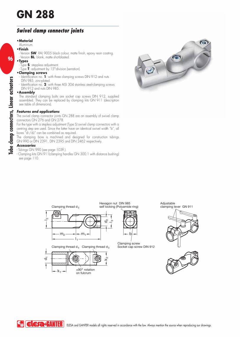
1
Tube
cla
mp
conn
ecto
rs, L
inea
r ac
tuat
ors
ELESA and GANTER models all rights reserved in accordance with the law. Always mention the source when reproducing our drawings.
9696
Features and applicationsThe swivel clamp connector joints GN 288 are an assembly of swivel clamp connectors GN 276 and GN 278. For the type with a stepless adjustment (Type S) swivel clamp connectors with a centring step are used. Since the latter have an identical swivel width “b”, all bores “d1/d2” can be combined as required. The clamping bore is machined and designed for construction tubings GN 990 or DIN 2391, DIN 2395 and DIN 2462 respectively. Accessories- Tubings GN 990 (see page 103ff.). - Clamping kits GN 911(clamping handles GN 300.1 with distance bushing)
see page 110.
MaterialAluminium.Finish- Version SW: RAL 9005 black colour, matte finish, epoxy resin coating. - Version BL: blank, matte shot-blasted.Types- Type S: steppless adjustment.- Type T: adjustment by 15°-division (serration).Clamping screws- Identification no. 1: with three clamping screws DIN 912 and nuts
DIN 985, zinc-plated.- Identification no. 2: with three AISI 304 stainless steel-clamping screws
DIN 912 and nuts DIN 985.AssemblyThe standard clamping bolts are socket cap screws DIN 912, supplied assembled. They can be replaced by clamping kits GN 911 (description see table of dimensions).
Swivel clamp connector joints
GN 288

Tube
cla
mp
conn
ecto
rs, L
inea
r ac
tuat
ors
ELESA and GANTER models all rights reserved in accordance with the law. Always mention the source when reproducing our drawings.
97
Standard Elements Main dimensionsClamping kits
for d3 for d4Description d1 d2 b Swivel width
d3 d4 k1 k2 l1 l2 m1 m2 g
GN 288-B20-B20-S-1-* B20 B20 40 M8 M8 42.5 40 147 52 43 72 GN 911-M8-32 GN 911-M8-35 410
GN 288-B20-B25-S-1-* B20 B25 40 M8 M8 42.5 40 147 52 43 72 GN 911-M8-32 GN 911-M8-35 410
GN 288-B20-B30-S-1-* B20 B30 40 M8 M8 42.5 40 147 52 43 72 GN 911-M8-32 GN 911-M8-35 345
GN 288-B25-B20-S-1-* B25 B20 40 M8 M8 42.5 40 147 52 43 72 GN 911-M8-32 GN 911-M8-35 375
GN 288-B25-B25-S-1-* B25 B25 40 M8 M8 42.5 40 147 52 43 72 GN 911-M8-32 GN 911-M8-35 375
GN 288-B25-B30-S-1-* B25 B30 40 M8 M8 42.5 40 147 52 43 72 GN 911-M8-32 GN 911-M8-35 375
GN 288-B30-B20-S-1-* B30 B20 40 M8 M8 42.5 40 147 52 43 72 GN 911-M8-32 GN 911-M8-35 325
GN 288-B30-B25-S-1-* B30 B25 40 M8 M8 42.5 40 147 52 43 72 GN 911-M8-32 GN 911-M8-35 340
GN 288-B30-B30-S-1-* B30 B30 40 M8 M8 42.5 40 147 52 43 72 GN 911-M8-32 GN 911-M8-35 325
GN 288-B40-B40-S-1-* B40 B40 65 M10 M10 74 65 230 77.5 70 115 GN 911-M10-55 GN 911-M10-63 1500
GN 288-B40-B42-S-1-* B40 B42 65 M10 M10 74 65 230 77.5 70 115 GN 911-M10-55 GN 911-M10-63 1510
GN 288-B40-B45-S-1-* B40 B45 65 M10 M10 74 65 230 77.5 70 115 GN 911-M10-55 GN 911-M10-63 1500
GN 288-B40-B48-S-1-* B40 B48 65 M10 M10 74 65 230 77.5 70 115 GN 911-M10-55 GN 911-M10-63 1500
GN 288-B40-B50-S-1-* B40 B50 65 M10 M10 74 65 230 77.5 70 115 GN 911-M10-55 GN 911-M10-63 1490
GN 288-B42-B40-S-1-* B42 B40 65 M10 M10 74 65 230 77.5 70 115 GN 911-M10-55 GN 911-M10-63 1470
GN 288-B42-B42-S-1-* B42 B42 65 M10 M10 74 65 230 77.5 70 115 GN 911-M10-55 GN 911-M10-63 1465
GN 288-B42-B45-S-1-* B42 B45 65 M10 M10 74 65 230 77.5 70 115 GN 911-M10-55 GN 911-M10-63 1460
GN 288-B42-B48-S-1-* B42 B48 65 M10 M10 74 65 230 77.5 70 115 GN 911-M10-55 GN 911-M10-63 1455
GN 288-B42-B50-S-1-* B42 B50 65 M10 M10 74 65 230 77.5 70 115 GN 911-M10-55 GN 911-M10-63 1450
GN 288-B45-B40-S-1-* B45 B40 65 M10 M10 74 65 230 77.5 70 115 GN 911-M10-55 GN 911-M10-63 1410
GN 288-B45-B42-S-1-* B45 B42 65 M10 M10 74 65 230 77.5 70 115 GN 911-M10-55 GN 911-M10-63 1400
GN 288-B45-B45-S-1-* B45 B45 65 M10 M10 74 65 230 77.5 70 115 GN 911-M10-55 GN 911-M10-63 1400
GN 288-B45-B48-S-1-* B45 B48 65 M10 M10 74 65 230 77.5 70 115 GN 911-M10-55 GN 911-M10-63 1395
GN 288-B45-B50-S-1-* B45 B50 65 M10 M10 74 65 230 77.5 70 115 GN 911-M10-55 GN 911-M10-63 1390
GN 288-B48-B40-S-1-* B48 B40 65 M10 M10 74 65 230 77.5 70 115 GN 911-M10-55 GN 911-M10-63 1270
GN 288-B48-B42-S-1-* B48 B42 65 M10 M10 74 65 230 77.5 70 115 GN 911-M10-55 GN 911-M10-63 1265
GN 288-B48-B45-S-1-* B48 B45 65 M10 M10 74 65 230 77.5 70 115 GN 911-M10-55 GN 911-M10-63 1260
GN 288-B48-B48-S-1-* B48 B48 65 M10 M10 74 65 230 77.5 70 115 GN 911-M10-55 GN 911-M10-63 1300
GN 288-B48-B50-S-1-* B48 B50 65 M10 M10 74 65 230 77.5 70 115 GN 911-M10-55 GN 911-M10-63 1295
GN 288-B50-B40-S-1-* B50 B40 65 M10 M10 74 65 230 77.5 70 115 GN 911-M10-55 GN 911-M10-63 1275
GN 288-B50-B42-S-1-* B50 B42 65 M10 M10 74 65 230 77.5 70 115 GN 911-M10-55 GN 911-M10-63 1270
GN 288-B50-B45-S-1-* B50 B45 65 M10 M10 74 65 230 77.5 70 115 GN 911-M10-55 GN 911-M10-63 1270
GN 288-B50-B48-S-1-* B50 B48 65 M10 M10 74 65 230 77.5 70 115 GN 911-M10-55 GN 911-M10-63 1265
GN 288-B50-B50-S-1-* B50 B50 65 M10 M10 74 65 230 77.5 70 115 GN 911-M10-55 GN 911-M10-63 1275
GN 288-B20-B20-T-1-* B20 B20 40 M8 M8 42.5 40 147 52 43 72 GN 911-M8-32 GN 911-M8-35 420
GN 288-B20-B25-T-1-* B20 B25 40 M8 M8 42.5 40 147 52 43 72 GN 911-M8-32 GN 911-M8-35 410
GN 288-B20-B30-T-1-* B20 B30 40 M8 M8 42.5 40 147 52 43 72 GN 911-M8-32 GN 911-M8-35 420
GN 288-B25-B20-T-1-* B25 B20 40 M8 M8 42.5 40 147 52 43 72 GN 911-M8-32 GN 911-M8-35 380
GN 288-B25-B25-T-1-* B25 B25 40 M8 M8 42.5 40 147 52 43 72 GN 911-M8-32 GN 911-M8-35 380
GN 288-B25-B30-T-1-* B25 B30 40 M8 M8 42.5 40 147 52 43 72 GN 911-M8-32 GN 911-M8-35 375
GN 288-B30-B20-T-1-* B30 B20 40 M8 M8 42.5 40 147 52 43 72 GN 911-M8-32 GN 911-M8-35 325
GN 288-B30-B25-T-1-* B30 B25 40 M8 M8 42.5 40 147 52 43 72 GN 911-M8-32 GN 911-M8-35 340
GN 288-B30-B30-T-1-* B30 B30 40 M8 M8 42.5 40 147 52 43 72 GN 911-M8-32 GN 911-M8-35 330
* Complete the description of the standard item needed by adding the finish of the connector clamps: BL (blank) or SW (black).

1
Tube
cla
mp
conn
ecto
rs, L
inea
r ac
tuat
ors
ELESA and GANTER models all rights reserved in accordance with the law. Always mention the source when reproducing our drawings.
9898
Standard Elements Main dimensionsClamping kits
for d3 for d4Description d1 Bore B
d2 Bore B
b Swivel width
d3 d4 k1 k2 l1 l2 m1 m2 g
GN 288-B40-B40-T-1-* B40 B40 65 M10 M10 74 65 230 77.5 70 115 GN 911-M10-55 GN 911-M10-63 1510
GN 288-B40-B42-T-1-* B40 B42 65 M10 M10 74 65 230 77.5 70 115 GN 911-M10-55 GN 911-M10-63 1510
GN 288-B40-B45-T-1-* B40 B45 65 M10 M10 74 65 230 77.5 70 115 GN 911-M10-55 GN 911-M10-63 1500
GN 288-B40-B48-T-1-* B40 B48 65 M10 M10 74 65 230 77.5 70 115 GN 911-M10-55 GN 911-M10-63 1500
GN 288-B40-B50-T-1-* B40 B50 65 M10 M10 74 65 230 77.5 70 115 GN 911-M10-55 GN 911-M10-63 1490
GN 288-B42-B40-T-1-* B42 B40 65 M10 M10 74 65 230 77.5 70 115 GN 911-M10-55 GN 911-M10-63 1470
GN 288-B42-B42-T-1-* B42 B42 65 M10 M10 74 65 230 77.5 70 115 GN 911-M10-55 GN 911-M10-63 1475
GN 288-B42-B45-T-1-* B42 B45 65 M10 M10 74 65 230 77.5 70 115 GN 911-M10-55 GN 911-M10-63 1460
GN 288-B42-B48-T-1-* B42 B48 65 M10 M10 74 65 230 77.5 70 115 GN 911-M10-55 GN 911-M10-63 1455
GN 288-B42-B50-T-1-* B42 B50 65 M10 M10 74 65 230 77.5 70 115 GN 911-M10-55 GN 911-M10-63 1450
GN 288-B45-B40-T-1-* B45 B40 65 M10 M10 74 65 230 77.5 70 115 GN 911-M10-55 GN 911-M10-63 1410
GN 288-B45-B42-T-1-* B45 B42 65 M10 M10 74 65 230 77.5 70 115 GN 911-M10-55 GN 911-M10-63 1405
GN 288-B45-B45-T-1-* B45 B45 65 M10 M10 74 65 230 77.5 70 115 GN 911-M10-55 GN 911-M10-63 1410
GN 288-B45-B48-T-1-* B45 B48 65 M10 M10 74 65 230 77.5 70 115 GN 911-M10-55 GN 911-M10-63 1395
GN 288-B45-B50-T-1-* B45 B50 65 M10 M10 74 65 230 77.5 70 115 GN 911-M10-55 GN 911-M10-63 1390
GN 288-B48-B40-T-1-* B48 B40 65 M10 M10 74 65 230 77.5 70 115 GN 911-M10-55 GN 911-M10-63 1270
GN 288-B48-B42-T-1-* B48 B42 65 M10 M10 74 65 230 77.5 70 115 GN 911-M10-55 GN 911-M10-63 1265
GN 288-B48-B45-T-1-* B48 B45 65 M10 M10 74 65 230 77.5 70 115 GN 911-M10-55 GN 911-M10-63 1260
GN 288-B48-B48-T-1-* B48 B48 65 M10 M10 74 65 230 77.5 70 115 GN 911-M10-55 GN 911-M10-63 1315
GN 288-B48-B50-T-1-* B48 B50 65 M10 M10 74 65 230 77.5 70 115 GN 911-M10-55 GN 911-M10-63 1295
GN 288-B50-B40-T-1-* B50 B40 65 M10 M10 74 65 230 77.5 70 115 GN 911-M10-55 GN 911-M10-63 1275
GN 288-B50-B42-T-1-* B50 B42 65 M10 M10 74 65 230 77.5 70 115 GN 911-M10-55 GN 911-M10-63 1275
GN 288-B50-B45-T-1-* B50 B45 65 M10 M10 74 65 230 77.5 70 115 GN 911-M10-55 GN 911-M10-63 1270
GN 288-B50-B48-T-1-* B50 B48 65 M10 M10 74 65 230 77.5 70 115 GN 911-M10-55 GN 911-M10-63 1265
GN 288-B50-B50-T-1-* B50 B50 65 M10 M10 74 65 230 77.5 70 115 GN 911-M10-55 GN 911-M10-63 1285
GN 288-B20-B20-S-2-* B20 B20 40 M8 M8 42.5 40 147 52 43 72 GN 911-M8-32 GN 911-M8-35 410
GN 288-B20-B25-S-2-* B20 B25 40 M8 M8 42.5 40 147 52 43 72 GN 911-M8-32 GN 911-M8-35 410
GN 288-B20-B30-S-2-* B20 B30 40 M8 M8 42.5 40 147 52 43 72 GN 911-M8-32 GN 911-M8-35 345
GN 288-B25-B20-S-2-* B25 B20 40 M8 M8 42.5 40 147 52 43 72 GN 911-M8-32 GN 911-M8-35 375
GN 288-B25-B25-S-2-* B25 B25 40 M8 M8 42.5 40 147 52 43 72 GN 911-M8-32 GN 911-M8-35 375
GN 288-B25-B30-S-2-* B25 B30 40 M8 M8 42.5 40 147 52 43 72 GN 911-M8-32 GN 911-M8-35 375
GN 288-B30-B20-S-2-* B30 B20 40 M8 M8 42.5 40 147 52 43 72 GN 911-M8-32 GN 911-M8-35 325
GN 288-B30-B25-S-2-* B30 B25 40 M8 M8 42.5 40 147 52 43 72 GN 911-M8-32 GN 911-M8-35 340
GN 288-B30-B30-S-2-* B30 B30 40 M8 M8 42.5 40 147 52 43 72 GN 911-M8-32 GN 911-M8-35 325
GN 288-B40-B40-S-2-* B40 B40 65 M10 M10 74 65 230 77.5 70 115 GN 911-M10-55 GN 911-M10-63 1500
GN 288-B40-B42-S-2-* B40 B42 65 M10 M10 74 65 230 77.5 70 115 GN 911-M10-55 GN 911-M10-63 1510
GN 288-B40-B45-S-2-* B40 B45 65 M10 M10 74 65 230 77.5 70 115 GN 911-M10-55 GN 911-M10-63 1500
GN 288-B40-B48-S-2-* B40 B48 65 M10 M10 74 65 230 77.5 70 115 GN 911-M10-55 GN 911-M10-63 1500
GN 288-B40-B50-S-2-* B40 B50 65 M10 M10 74 65 230 77.5 70 115 GN 911-M10-55 GN 911-M10-63 1490
GN 288-B42-B40-S-2-* B42 B40 65 M10 M10 74 65 230 77.5 70 115 GN 911-M10-55 GN 911-M10-63 1470
GN 288-B42-B42-S-2-* B42 B42 65 M10 M10 74 65 230 77.5 70 115 GN 911-M10-55 GN 911-M10-63 1465
GN 288-B42-B45-S-2-* B42 B45 65 M10 M10 74 65 230 77.5 70 115 GN 911-M10-55 GN 911-M10-63 1460
GN 288-B42-B48-S-2-* B42 B48 65 M10 M10 74 65 230 77.5 70 115 GN 911-M10-55 GN 911-M10-63 1455
GN 288-B42-B50-S-2-* B42 B50 65 M10 M10 74 65 230 77.5 70 115 GN 911-M10-55 GN 911-M10-63 1450
GN 288-B45-B40-S-2-* B45 B40 65 M10 M10 74 65 230 77.5 70 115 GN 911-M10-55 GN 911-M10-63 1410
GN 288-B45-B42-S-2-* B45 B42 65 M10 M10 74 65 230 77.5 70 115 GN 911-M10-55 GN 911-M10-63 1405
GN 288-B45-B45-S-2-* B45 B45 65 M10 M10 74 65 230 77.5 70 115 GN 911-M10-55 GN 911-M10-63 1400
* Complete the description of the standard item needed by adding the finish of the connector clamps: BL (blank) or SW (black).

Tube
cla
mp
conn
ecto
rs, L
inea
r ac
tuat
ors
ELESA and GANTER models all rights reserved in accordance with the law. Always mention the source when reproducing our drawings.
99
Standard Elements Main dimensionsClamping kits
for d3 for d4Description d1 Bore B
d2 Bore B
b Swivel width
d3 d4 k1 k2 l1 l2 m1 m2 g
GN 288-B45-B48-S-2-* B45 B48 65 M10 M10 74 65 230 77.5 70 115 GN 911-M10-55 GN 911-M10-63 1395
GN 288-B45-B50-S-2-* B45 B50 65 M10 M10 74 65 230 77.5 70 115 GN 911-M10-55 GN 911-M10-63 1390
GN 288-B48-B40-S-2-* B48 B40 65 M10 M10 74 65 230 77.5 70 115 GN 911-M10-55 GN 911-M10-63 1270
GN 288-B48-B42-S-2-* B48 B42 65 M10 M10 74 65 230 77.5 70 115 GN 911-M10-55 GN 911-M10-63 1265
GN 288-B48-B45-S-2-* B48 B45 65 M10 M10 74 65 230 77.5 70 115 GN 911-M10-55 GN 911-M10-63 1260
GN 288-B48-B48-S-2-* B48 B48 65 M10 M10 74 65 230 77.5 70 115 GN 911-M10-55 GN 911-M10-63 1300
GN 288-B48-B50-S-2-* B48 B50 65 M10 M10 74 65 230 77.5 70 115 GN 911-M10-55 GN 911-M10-63 1295
GN 288-B50-B40-S-2-* B50 B40 65 M10 M10 74 65 230 77.5 70 115 GN 911-M10-55 GN 911-M10-63 1275
GN 288-B50-B42-S-2-* B50 B42 65 M10 M10 74 65 230 77.5 70 115 GN 911-M10-55 GN 911-M10-63 1275
GN 288-B50-B45-S-2-* B50 B45 65 M10 M10 74 65 230 77.5 70 115 GN 911-M10-55 GN 911-M10-63 1270
GN 288-B50-B48-S-2-* B50 B48 65 M10 M10 74 65 230 77.5 70 115 GN 911-M10-55 GN 911-M10-63 1265
GN 288-B50-B50-S-2-* B50 B50 65 M10 M10 74 65 230 77.5 70 115 GN 911-M10-55 GN 911-M10-63 1275
GN 288-B20-B20-T-2-* B20 B20 40 M8 M8 42.5 40 147 52 43 72 GN 911-M8-32 GN 911-M8-35 420
GN 288-B20-B25-T-2-* B20 B25 40 M8 M8 42.5 40 147 52 43 72 GN 911-M8-32 GN 911-M8-35 410
GN 288-B20-B30-T-2-* B20 B30 40 M8 M8 42.5 40 147 52 43 72 GN 911-M8-32 GN 911-M8-35 420
GN 288-B25-B20-T-2-* B25 B20 40 M8 M8 42.5 40 147 52 43 72 GN 911-M8-32 GN 911-M8-35 380
GN 288-B25-B25-T-2-* B25 B25 40 M8 M8 42.5 40 147 52 43 72 GN 911-M8-32 GN 911-M8-35 380
GN 288-B25-B30-T-2-* B25 B30 40 M8 M8 42.5 40 147 52 43 72 GN 911-M8-32 GN 911-M8-35 380
GN 288-B30-B20-T-2-* B30 B20 40 M8 M8 42.5 40 147 52 43 72 GN 911-M8-32 GN 911-M8-35 325
GN 288-B30-B25-T-2-* B30 B25 40 M8 M8 42.5 40 147 52 43 72 GN 911-M8-32 GN 911-M8-35 340
GN 288-B30-B30-T-2-* B30 B30 40 M8 M8 42.5 40 147 52 43 72 GN 911-M8-32 GN 911-M8-35 330
GN 288-B40-B40-T-2-* B40 B40 65 M10 M10 74 65 230 77.5 70 115 GN 911-M10-55 GN 911-M10-63 1510
GN 288-B40-B42-T-2-* B40 B42 65 M10 M10 74 65 230 77.5 70 115 GN 911-M10-55 GN 911-M10-63 1510
GN 288-B40-B45-T-2-* B40 B45 65 M10 M10 74 65 230 77.5 70 115 GN 911-M10-55 GN 911-M10-63 1500
GN 288-B40-B48-T-2-* B40 B48 65 M10 M10 74 65 230 77.5 70 115 GN 911-M10-55 GN 911-M10-63 1500
GN 288-B40-B50-T-2-* B40 B50 65 M10 M10 74 65 230 77.5 70 115 GN 911-M10-55 GN 911-M10-63 1490
GN 288-B42-B40-T-2-* B42 B40 65 M10 M10 74 65 230 77.5 70 115 GN 911-M10-55 GN 911-M10-63 1470
GN 288-B42-B42-T-2-* B42 B42 65 M10 M10 74 65 230 77.5 70 115 GN 911-M10-55 GN 911-M10-63 1475
GN 288-B42-B45-T-2-* B42 B45 65 M10 M10 74 65 230 77.5 70 115 GN 911-M10-55 GN 911-M10-63 1460
GN 288-B42-B48-T-2-* B42 B48 65 M10 M10 74 65 230 77.5 70 115 GN 911-M10-55 GN 911-M10-63 1455
GN 288-B42-B50-T-2-* B42 B50 65 M10 M10 74 65 230 77.5 70 115 GN 911-M10-55 GN 911-M10-63 1450
GN 288-B45-B40-T-2-* B45 B40 65 M10 M10 74 65 230 77.5 70 115 GN 911-M10-55 GN 911-M10-63 1410
GN 288-B45-B42-T-2-* B45 B42 65 M10 M10 74 65 230 77.5 70 115 GN 911-M10-55 GN 911-M10-63 1405
GN 288-B45-B45-T-2-* B45 B45 65 M10 M10 74 65 230 77.5 70 115 GN 911-M10-55 GN 911-M10-63 1400
GN 288-B45-B48-T-2-* B45 B48 65 M10 M10 74 65 230 77.5 70 115 GN 911-M10-55 GN 911-M10-63 1395
GN 288-B45-B50-T-2-* B45 B50 65 M10 M10 74 65 230 77.5 70 115 GN 911-M10-55 GN 911-M10-63 1390
GN 288-B48-B40-T-2-* B48 B40 65 M10 M10 74 65 230 77.5 70 115 GN 911-M10-55 GN 911-M10-63 1270
GN 288-B48-B42-T-2-* B48 B42 65 M10 M10 74 65 230 77.5 70 115 GN 911-M10-55 GN 911-M10-63 1265
GN 288-B48-B45-T-2-* B48 B45 65 M10 M10 74 65 230 77.5 70 115 GN 911-M10-55 GN 911-M10-63 1260
GN 288-B48-B48-T-2-* B48 B48 65 M10 M10 74 65 230 77.5 70 115 GN 911-M10-55 GN 911-M10-63 1315
GN 288-B48-B50-T-2-* B48 B50 65 M10 M10 74 65 230 77.5 70 115 GN 911-M10-55 GN 911-M10-63 1295
GN 288-B50-B40-T-2-* B50 B40 65 M10 M10 74 65 230 77.5 70 115 GN 911-M10-55 GN 911-M10-63 1275
GN 288-B50-B42-T-2-* B50 B42 65 M10 M10 74 65 230 77.5 70 115 GN 911-M10-55 GN 911-M10-63 1275
GN 288-B50-B45-T-2-* B50 B45 65 M10 M10 74 65 230 77.5 70 115 GN 911-M10-55 GN 911-M10-63 1270
GN 288-B50-B48-T-2-* B50 B48 65 M10 M10 74 65 230 77.5 70 115 GN 911-M10-55 GN 911-M10-63 1265
GN 288-B50-B50-T-2-* B50 B50 65 M10 M10 74 65 230 77.5 70 115 GN 911-M10-55 GN 911-M10-63 1285
* Complete the description of the standard item needed by adding the finish of the connector clamps: BL (blank) or SW (black).

1
Tube
cla
mp
conn
ecto
rs, L
inea
r ac
tuat
ors
ELESA and GANTER models all rights reserved in accordance with the law. Always mention the source when reproducing our drawings.
100100
Standard Elements Main dimensions
Description d1 for sensor
b Swivel width
d2 d3 l m1 m2 t1 -0.5 t2 x1 x2 y g
GN 271.4-B12-25-SW B12 25 30 5.5 36.5 24 25 11.5 7 50 38 35 40
GN 271.4-B18-25-SW B18 25 30 5.5 36.5 24 25 11.5 7 50 38 35 38
MaterialAluminium.FinishRAL 9005 black colour, matte finish, epoxy resin coating.
Sensor holders
GN 271.4

Tube
cla
mp
conn
ecto
rs, L
inea
r ac
tuat
ors
ELESA and GANTER models all rights reserved in accordance with the law. Always mention the source when reproducing our drawings.
101
Standard Elements Main dimensions
Description d1 for sensor
b Swivel width
d2 d3 l m1 m2 t1 -0.5 t2 x1 x2 y1 y2 g
GN 272.4-B18-40-SW B18 40 50 6.5 52.5 32.5 30 10 7 60 42 60 42 110
GN 272.4-B30-40-SW B30 40 50 6.5 52.5 32.5 30 10 7 60 42 60 42 100
MaterialAluminium.FinishRAL 9005 black colour, matte finish, epoxy resin coating.
Sensor holders
GN 272.4

1
Tube
cla
mp
conn
ecto
rs, L
inea
r ac
tuat
ors
ELESA and GANTER models all rights reserved in accordance with the law. Always mention the source when reproducing our drawings.
102102
Standard Elements Main dimensionsClamping kits
for d4Description d1
d2 for sensor
b Swivel width
d3 d4 k l m t -0.5 g
GN 273.4-B12-B12-1-SW B12 B12 25 20 M6 25 64 29.5 11.5 GN 911-M6-22 60
GN 273.4-B14-B12-1-SW B14 B12 25 20 M6 25 64 29.5 11.5 GN 911-M6-22 60
GN 273.4-B16-B12-1-SW B16 B12 25 20 M6 25 64 29.5 11.5 GN 911-M6-22 60
GN 273.4-B18-B12-1-SW B18 B12 25 20 M6 25 64 29.5 11.5 GN 911-M6-22 60
GN 273.4-B12-B18-1-SW B12 B18 25 20 M6 25 64 29.5 11.5 GN 911-M6-22 60
GN 273.4-B14-B18-1-SW B14 B18 25 20 M6 25 64 29.5 11.5 GN 911-M6-22 60
GN 273.4-B16-B18-1-SW B16 B18 25 20 M6 25 64 29.5 11.5 GN 911-M6-22 60
GN 273.4-B18-B18-1-SW B18 B18 25 20 M6 25 64 29.5 11.5 GN 911-M6-22 60
GN 273.4-B12-B12-2-SW B12 B12 25 20 M6 25 64 29.5 11.5 GN 911-M6-22 60
GN 273.4-B14-B12-2-SW B14 B12 25 20 M6 25 64 29.5 11.5 GN 911-M6-22 60
GN 273.4-B16-B12-2-SW B16 B12 25 20 M6 25 64 29.5 11.5 GN 911-M6-22 60
GN 273.4-B18-B12-2-SW B18 B12 25 20 M6 25 64 29.5 11.5 GN 911-M6-22 60
GN 273.4-B12-B18-2-SW B12 B18 25 20 M6 25 64 29.5 11.5 GN 911-M6-22 60
GN 273.4-B14-B18-2-SW B14 B18 25 20 M6 25 64 29.5 11.5 GN 911-M6-22 60
GN 273.4-B16-B18-2-SW B16 B18 25 20 M6 25 64 29.5 11.5 GN 911-M6-22 60
GN 273.4-B18-B18-2-SW B18 B18 25 20 M6 25 64 29.5 11.5 GN 911-M6-22 60
Features and applicationsThe aluminium design guarantees a highly safe and secure clamping action and safe positioning. The clamping bore of the sensor holders GN 273.4 is machined and designed for construction tubings GN 990 or DIN 2391, DIN 2395 and DIN 2462 respectively. Accessories- Tubings GN 990 (see page 103ff.). - Clamping kits GN 911 (clamping handles GN 300.1 with distance bushing)
see page 110.
MaterialAluminium.FinishRAL 9005 black colour, matte finish, epoxy resin coating.Clamping screws- Identification no. 1: with clamping screw DIN 912 and nut DIN 985,
zinc-plated.- Identification no. 2: with AISI 304 stainless steel-clamping screw
DIN 912 and nut DIN 985.AssemblyThe standard clamping bolts are socket cap screws DIN 912, supplied assembled. They can be replaced by clamping kits GN 911 (description see table of dimensions).
Sensor holders
GN 273.4

Tube
cla
mp
conn
ecto
rs, L
inea
r ac
tuat
ors
ELESA and GANTER models all rights reserved in accordance with the law. Always mention the source when reproducing our drawings.
103
Standard Elements Main dimensions
Description d1 s1 l ±0.5 d2 s2 w1 w2 g
GN 990-NI-D10-100-BL D10 ±0.1 - 100 7 - 1.5 - 32
GN 990-NI-D12-100-BL D12 ±0.1 - 100 9 - 1.5 - 40
GN 990-NI-D14-100-BL D14 ±0.1 - 100 11 - 1.5 - 47
GN 990-NI-D15-100-BL D15 ±0.1 - 100 12 - 1.5 - 52
GN 990-NI-D16-100-BL D16 ±0.1 - 100 13 - 1.5 - 54
GN 990-NI-D18-100-BL D18 ±0.1 - 100 15 - 1.5 - 61
GN 990-NI-D20-100-BL D20 ±0.1 - 100 16 - 2 - 89
GN 990-NI-D25-100-BL D25 ±0.1 - 100 21 - 2 - 114
GN 990-NI-D30-100-BL D30 ±0.1 - 100 26 - 2 - 139
GN 990-NI-D32-100-BL D32 ±0.15 - 100 28 - 2 - 149
GN 990-NI-D35-100-BL D35 ±0.15 - 100 31 - 2 - 164
GN 990-NI-D40-100-BL D40 ±0.15 - 100 34 - 3 - 276
GN 990-NI-D50-100-BL D50 ±0.2 - 100 44 - 3 - 350
GN 990-NI-D60-100-BL D60 ±0.25 - 100 52 - 4 - 550
GN 990-NI-V20-100-BL - V20 100 - 16 - 2 113
GN 990-NI-V25-100-BL - V25 100 - 21 - 2 145
GN 990-NI-V30-100-BL - V30 100 - 26 - 2 176
GN 990-NI-V40-100-BL - V40 100 - 34 - 3 335
GN 990-NI-V45-100-BL - V45 100 - 39 - 3 382
GN 990-NI-V50-100-BL - V50 100 - 44 - 3 431
MaterialAISI 304 stainless steel NI, blank BL untreated.
Construction tubings
GN 990-NI
Features and applicationsConstruction tubings GN 990-NI can be supplied in any length up to 3000 mm. The tolerances specified for the outside diameter of the round construction tubings comply with the requirements for split mono-block connector clamps. Otherwise the tolerances comply with DIN 2391, DIN 2395 and DIN 2462. Two-piece connector clamps allow obviously larger tolerances on round and square construction tubings.Accessories- Tube end plugs GN 991 (see page 106). - Insert bushes GN 992 (see page 108).

1
Tube
cla
mp
conn
ecto
rs, L
inea
r ac
tuat
ors
ELESA and GANTER models all rights reserved in accordance with the law. Always mention the source when reproducing our drawings.
104104 Features and applications
Construction tubings GN 990 can be supplied in any length up to 3000 mm. The tolerances specified for the outside diameter of the round construction tubings comply with the requirements for split mono-block connector clamps. Otherwise the tolerances comply with DIN 2391, DIN 2395 and DIN 2462. Two-piece connector clamps allow obviously larger tolerances on round and square construction tubings.Accessories- Tube end plugs GN 991 (see page 106). - Insert bushes GN 992 (see page 108).
Material- Steel ST, zinc-plated ZB, blue anodised. - Aluminium AL, blank BL, untreated.- Aluminium AL, anodised EL, natural colour.
Construction tubings
GN 990
Standard Elements Main dimensions
Description d1 s1 Square V
l ±0.5 d2 s2 w1 w2 g
GN 990-ST-D10-100-ZB D10 ±0.1 - 100 7 - 1.5 - 31
GN 990-ST-D12-100-ZB D12 ±0.1 - 100 9 - 1.5 - 40
GN 990-ST-D14-100-ZB D14 ±0.1 - 100 11 - 1.5 - 46
GN 990-ST-D15-100-ZB D15 ±0.1 - 100 12 - 1.5 - 52
GN 990-ST-D16-100-ZB D16 ±0.1 - 100 13 - 1.5 - 54
GN 990-ST-D18-100-ZB D18 ±0.1 - 100 15 - 1.5 - 61
GN 990-ST-D20-100-ZB D20 ±0.1 - 100 16 - 2 - 89
GN 990-ST-D25-100-ZB D25 ±0.1 - 100 21 - 2 - 113
GN 990-ST-D30-100-ZB D30 ±0.1 - 100 26 - 2 - 138
GN 990-ST-D32-100-ZB D32 ±0.15 - 100 28 - 2 - 148
GN 990-ST-D35-100-ZB D35 ±0.15 - 100 31 - 2 - 163
GN 990-ST-D40-100-ZB D40 ±0.15 - 100 34 - 3 - 274
GN 990-ST-D42-100-ZB D42 ±0.2 - 100 36 - 3 - 288
GN 990-ST-D45-100-ZB D45 ±0.2 - 100 39 - 3 - 312
GN 990-ST-D48-100-ZB D48 ±0.2 - 100 42 - 3 - 334
GN 990-ST-D50-100-ZB D50 ±0.2 - 100 44 - 3 - 348
GN 990-ST-D55-100-ZB D55 ±0.25 - 100 47 - 4 - 506
GN 990-ST-D60-100-ZB D60 ±0.25 - 100 52 - 4 - 550

Tube
cla
mp
conn
ecto
rs, L
inea
r ac
tuat
ors
ELESA and GANTER models all rights reserved in accordance with the law. Always mention the source when reproducing our drawings.
105
Standard Elements Main dimensions
Description d1 s1 Square V
l ±0,5 d2 s2 w1 w2 g
GN 990-ST-V20-100-ZB - V20 100 - 16 - 2 112
GN 990-ST-V25-100-ZB - V25 100 - 21 - 2 144
GN 990-ST-V30-100-ZB - V30 100 - 26 - 2 175
GN 990-ST-V35-100-ZB - V35 100 - 31 - 2 206
GN 990-ST-V40-100-ZB - V40 100 - 34 - 3 333
GN 990-ST-V45-100-ZB - V45 100 - 39 - 3 380
GN 990-ST-V50-100-ZB - V50 100 - 44 - 3 428
GN 990-AL-D10-100-* D10 ±0.1 - 100 7 - 1.5 - 11
GN 990-AL-D12-100-* D12 ±0.1 - 100 9 - 1.5 - 14
GN 990-AL-D14-100-* D14 ±0.1 - 100 11 - 1.5 - 16
GN 990-AL-D15-100-* D15 ±0.1 - 100 12 - 1.5 - 18
GN 990-AL-D16-100-* D16 ±0.1 - 100 13 - 1.5 - 18
GN 990-AL-D18-100-* D18 ±0.1 - 100 15 - 1.5 - 21
GN 990-AL-D20-100-* D20 ±0.1 - 100 16 - 2 - 31
GN 990-AL-D25-100-* D25 ±0.1 - 100 21 - 2 - 39
GN 990-AL-D30-100-* D30 ±0.1 - 100 26 - 2 - 48
GN 990-AL-D32-100-* D32 ±0.15 - 100 28 - 2 - 51
GN 990-AL-D35-100-* D35 ±0.15 - 100 31 - 2 - 56
GN 990-AL-D40-100-* D40 ±0.15 - 100 34 - 3 - 94
GN 990-AL-D42-100-* D42 ±0.2 - 100 36 - 3 - 99
GN 990-AL-D45-100-* D45 ±0.2 - 100 39 - 3 - 107
GN 990-AL-D48-100-* D48 ±0.2 - 100 42 - 3 - 115
GN 990-AL-D50-100-* D50 ±0.2 - 100 44 - 3 - 120
GN 990-AL-D60-100-* D60 ±0.25 - 100 52 - 4 - 188
GN 990-AL-V10-100-* - V10 100 - 8 - 1.5 10
GN 990-AL-V12-100-* - V12 100 - 10 - 1.5 12
GN 990-AL-V16-100-* - V16 100 - 14 - 1.5 16
GN 990-AL-V20-100-* - V20 100 - 16 - 2 39
GN 990-AL-V25-100-* - V25 100 - 21 - 2 50
GN 990-AL-V30-100-* - V30 100 - 26 - 2 61
GN 990-AL-V35-100-* - V35 100 - 31 - 2 71
GN 990-AL-V40-100-* - V40 100 - 34 - 3 120
GN 990-AL-V45-100-* - V45 100 - 39 - 3 136
GN 990-AL-V50-100-* - V50 100 - 44 - 3 152
* Complete the description of the standard item needed by adding the finish of the aluminium construction tubings: BL (blank) or EL (anodized).

1
Tube
cla
mp
conn
ecto
rs, L
inea
r ac
tuat
ors
ELESA and GANTER models all rights reserved in accordance with the law. Always mention the source when reproducing our drawings.
106106
Standard Elements Main dimensions
Description d1 s1 d2 ≈ s2 ≈ l1 ≈ l2 ≈ l3 g
GN 991-D10 D10 - 9 - 15 3 - 1
GN 991-D12 D12 - 11 - 14 4 - 1
GN 991-D14 D14 - 13 - 13 4 - 1
GN 991-D15 D15 - 14 - 16 4 - 1
GN 991-D16 D16 - 14.5 - 15 5 - 1
GN 991-D18 D18 - 17 - 16 5 - 2
GN 991-D20 D20 - 19 - 16 5 - 2
GN 991-D25 D25 - 23.5 - 16 5 - 3
GN 991-D30 D30 - 29 - 16 5 - 3
GN 991-D32 D32 - 30.5 - 16 5 - 4
GN 991-D35 D35 - 34 - 16 5 - 5
GN 991-D40 D40 - 35 - 17 5 - 6
GN 991-D42 D42 - 38.5 - 17 5 - 6
GN 991-D45 D45 - 44 - 16 5 - 7
GN 991-D48 D48 - 45 - 20 5 - 9
GN 991-D50 D50 - 45.5 - 23 5 - 11
GN 991-D55 D55 - 53 - 19 5 - 11
GN 991-D60 D60 - 58 - 22 4 - 15
GN 991-V20 - V20 - 19 - 5 17 2
GN 991-V25 - V25 - 24 - 5 17 4
GN 991-V30 - V30 - 29 - 5 17 5
GN 991-V40 - V40 - 36 - 5 20 9
GN 991-V45 - V45 - 44 - 5 20 10
GN 991-V50 - V50 - 46 - 5 24 15
MaterialPolyamide based (PA) technopolymer.ColourBlack, matte finish.
Tube end plugs
GN 991
Features and applicationsTube end plugs GN 991 have been designed for sealing tube ends for safety or optical reasons. They are inserted into the tube end either by hand or with a mallet.Accessories- Construction tubings GN 990 (see page 103ff.). - Insert bushes GN 992 (see page 108).

Tube
cla
mp
conn
ecto
rs, L
inea
r ac
tuat
ors
ELESA and GANTER models all rights reserved in accordance with the law. Always mention the source when reproducing our drawings.
107
Levelling elements GN 343.2 (see main catalogue page 724ff.) Levelling elements LS.A (see main catalogue page 716ff.) Levelling elements LV.A (see main catalogue page 730ff.) with insert bushes. for construction tubings GN 990 (see page103ff.) in Technopolymer NDX.Q (see main catalogue page 760) in Technopolymer ND.Q (see main catalogue page 762) in Aluminium GN 992 (see page 108)

1
Tube
cla
mp
conn
ecto
rs, L
inea
r ac
tuat
ors
ELESA and GANTER models all rights reserved in accordance with the law. Always mention the source when reproducing our drawings.
108108
Features and applicationsInsert bushes GN 992 serve as end plugs in tubing which offer the additional facility for fitting threaded levelling feet. Insert bushes can bridge an internal diameter tolerance on both round as well as square tube of ± 0,5 mm. For this purpose lamellas are available. Insert bushes are fitted with a mallet.AccessoriesConstruction tubings GN 990 (see page 103ff.).
MaterialAluminium, blank.
Insert bushes
GN 992

Tube
cla
mp
conn
ecto
rs, L
inea
r ac
tuat
ors
ELESA and GANTER models all rights reserved in accordance with the law. Always mention the source when reproducing our drawings.
109
Standard Elements Main dimensions
Description d1 s1 d2 d3 d4 l1 l2 l3 +0.5 s2 Internal square
g
GN 992-D20-M8 D20 - M8 16 16.5 29.5 2.5 16 - 10
GN 992-D25-M8 D25 - M8 21 21.5 33.5 2.5 16 - 22
GN 992-D25-M10 D25 - M10 21 21.5 33.5 2.5 16 - 22
GN 992-D30-M8 D30 - M8 26 26.5 33.5 2.5 18 - 34
GN 992-D30-M10 D30 - M10 26 26.5 33.5 2.5 18 - 45
GN 992-D32-M8 D32 - M8 28 28.5 33.5 2.5 18 - 50
GN 992-D32-M10 D32 - M10 28 28.5 33.5 2.5 18 - 50
GN 992-D35-M10 D35 - M10 31 31.5 37.5 2.5 24 - 55
GN 992-D35-M12 D35 - M12 31 31.5 37.5 2.5 24 - 55
GN 992-D40-M10 D40 - M10 34 34.5 41.5 2.5 24 - 78
GN 992-D40-M12 D40 - M12 34 34.5 41.5 2.5 24 - 78
GN 992-D42-M10 D42 - M10 36 36.5 41.5 2.5 24 - 90
GN 992-D42-M12 D42 - M12 36 36.5 41.5 2.5 24 - 90
GN 992-D45-M12 D45 - M12 39 39.5 45.5 2.5 30 - 110
GN 992-D45-M16 D45 - M16 39 39.5 45.5 2.5 30 - 110
GN 992-D48-M12 D48 - M12 42 42.5 45.5 2.5 30 - 130
GN 992-D48-M16 D48 - M16 42 42.5 45.5 2.5 30 - 130
GN 992-D50-M12 D50 - M12 44 44.5 45.5 2.5 30 - 145
GN 992-D50-M16 D50 - M16 44 44.5 45.5 2.5 30 - 145
GN 992-V20-M8 - V20 M8 - 16.5 29.5 2.5 16 16 11
GN 992-V25-M8 - V25 M8 - 21.5 33.5 2.5 16 21 22
GN 992-V25-M10 - V25 M10 - 21.5 33.5 2.5 16 21 22
GN 992-V30-M8 - V30 M8 - 26.5 33.5 2.5 18 26 52
GN 992-V30-M10 - V30 M10 - 26.5 33.5 2.5 18 26 52
GN 992-V40-M10 - V40 M10 - 34.5 41.5 2.5 24 34 115
GN 992-V40-M12 - V40 M12 - 34.5 41.5 2.5 24 34 88
GN 992-V45-M12 - V45 M12 - 39.5 45.5 2.5 30 39 165
GN 992-V45-M16 - V45 M16 - 39.5 45.5 2.5 30 39 165
GN 992-V50-M12 - V50 M12 - 44.5 45.5 2.5 30 44 215
GN 992-V50-M16 - V50 M16 - 44.5 45.5 2.5 30 44 215

1
Tube
cla
mp
conn
ecto
rs, L
inea
r ac
tuat
ors
ELESA and GANTER models all rights reserved in accordance with the law. Always mention the source when reproducing our drawings.
110110
Standard Elements Main dimensions
Description d1 d2 l1 l2 l3 l4 h1 h2 g
GN 911-M6-22 M6 9.9 45 22 19 3 24.5 35 40
GN 911-M6-25 M6 9.9 45 25 22 3 24.5 35 41
GN 911-M8-32 M8 12.9 63 32 27.5 4.5 31 45 61
GN 911-M8-35 M8 12.9 63 35 30.5 4.5 31 45 61
GN 911-M8-40 M8 12.9 63 40 35.5 4.5 31 45 61
GN 911-M8-45 M8 12.9 63 45 40.5 4.5 31 45 61
GN 911-M8-50 M8 12.9 63 50 45.5 4.5 31 45 61
GN 911-M8-55 M8 12.9 63 55 50.5 4.5 31 45 62
GN 911-M10-40 M10 16.9 78 40 34.5 5.5 36 55 146
GN 911-M10-50 M10 16.9 78 50 44.5 5.5 36 55 152
GN 911-M10-55 M10 16.9 78 55 49.5 5.5 36 55 155
GN 911-M10-63 M10 16.9 78 63 57.5 5.5 36 55 159
GN 911-M10-70 M10 16.9 78 70 64.5 5.5 36 55 140
GN 911-M10-80 M10 16.9 78 80 74.5 5.5 36 55 200
Features and applicationsThe clamping kit is an adjustable handle for clamp connectors.The clamping kits GN 911 can be used instead of the hexagon socket cap screws DIN 912 for connector clamps.The table of the connector clamps shows the corresponding clamping kit for each clamping point.
Lever bodyZinc alloy die-cast, epoxy resin coating.ColourRAL 9006 silver.Clamping elementAISI 303 stainless steel with threaded hole and toothed element for coupling to the lever body, AISI 303 stainless steel screw and AISI 301 stainless steel return spring.Locking nutAISI 304 stainless steel.Distance bushingAISI 303 stainless steel.
GN 911Clamping kits

The lead screw with a trapezoidal thread mounted on a thrust ball bearing at both ends is fitted with a follower nut. The follower nut carries an adaptor bar that protrudes through the tube slot thus preventing the follower nut from rotating. The adaptor bar is linked to sliding units. Linear actuators have been designed for hand operation (handwheel).
The positioning accuracy is 0.2 mm at 300 mm travel.
Guide tubes are available in chrome plated steel (SCR) or Stainless Steel (NI). They are produced within the tolerance band of precision steel tubes DIN 2391 and DIN 2462 respectively.
Within the extensive range of tube clamping connectors, there are numerous components available for constructing jigs and fixtures which are designed to perform linear operations.
In addition digital position indicators (DD52R / DD51) can be added to monitor the movement and positioning.
For applications with high torsional moments Mx it is recommended to use square linear actuators.
For this type there are also a numerous components within the tube clamp connectors range available. The slide units of the square linear actuators are built of split elements. Therefore there are no special requirements regarding the tolerance of the square tubes.
Description
Tube
cla
mp
conn
ecto
rs, L
inea
r ac
tuat
ors
ELESA and GANTER models all rights reserved in accordance with the law. Always mention the source when reproducing our drawings.
111
Technical data and load data of linear actuators
The load data are applicable to linear actuators GN 291, GN 292, GN 293 Steel (SCR) or Stainless Steel (NI). At the values indicated above, a temporary linear tube deformation of approximately 0.5 mm will occur.
Ø Linear actuator Fx in N Fy in N Fz in N Mx in Nm My in Nm Mz in Nm
l = 500 l = 1000 l = 1500 l = 500 l = 1000 l = 1500
18 400 80 15 - 65 10 - 1.5 4.5 4.5
30 850 500 70 15 550 55 10 6.5 15 15
40 1100 2150 250 65 1900 150 50 15 42 42
50 1750 3100 650 150 3100 650 150 29 69 69
60 2600 4550 1500 400 4550 1400 350 45 125 125

Linear actuators GN 291 (see page 113ff.) are available with left or right hand thread, with protruding shaft at either one or both ends with one linear actuator connector GN 146.1(see page 127ff.).
Square linear actuators GN 291.1 (standard sheet page 140ff.) is available with left or right hand thread, with protruding shaft at eit-her one or both ends with one linear actuator connector GN 147.1 (see page 131).
Description
Linear actuators GN 292 (standard sheet page 70) are available with left and right hand thread, with protruding shaft at either one or both ends and two linear actuator connectors GN 146.1 (see page 75).
Square linear actuators GN 292.1 on request.
Description
Linear actuators GN 293 (see page 71) are available with two separate spindles with left or right hand thread, or alternatively two left or two right hand threads with protruding shaft ends and two linear actuator connectors GN 146.1 (see page 75).
Square linear actuators GN 293.1 on request.
Description
Tube
cla
mp
conn
ecto
rs, L
inea
r ac
tuat
ors
ELESA and GANTER models all rights reserved in accordance with the law. Always mention the source when reproducing our drawings.
112
Assembly examples of linear actuators

Tube
cla
mp
conn
ecto
rs, L
inea
r ac
tuat
ors
ELESA and GANTER models all rights reserved in accordance with the law. Always mention the source when reproducing our drawings.
113
of the order )( are included part
Lead nut2,5 2,5
3l l 3
Follower
2m
for the slider2 fixing screws
with thread d3
3Thread d
Trapez threadSpindle with
Plastic cover
4l 4ll 2Key DIN 6885
= Travel1l
1m
d2
d1
Features and applicationsIn addition to the standard travel lengths specified in the above table for linear actuator GN 291 any length inside the maximum length is available. Besides the extensive range of tube clamp connectors there are a number of additional components for mounting on the linear actuator to build slider units. In order to measure the movement and positioning of the sliders, digital as well as analogue position indicators can be added.Accessories- Housings GN 298 (see page 159).- Bevel gear wheels GN 297 (see page 160).- Installation kits for linear actuators GN 295 (see page 153).- Longitudinal scales GN 299 (see page 154).Special executions on request (For sufficient quantities)Guide tube, precision AISI 303 stainless steel NI, DIN 2462 (all types).
Guide tubePrecision steel tube, chrome-plated SCR, DIN 2391.Trapezodial thread on shaftSteel thrust ball bearings.Follower nutGun metal.End capsPlastic.Types- Type R1: Right hand thread, single shaft end only.- Type R2: Right hand thread, two shaft ends.- Type L1: Left hand thread, single shaft end only.- Type L2: Left hand thread, two shaft ends.AssemblySliders, connector clamps and accessoires have to be ordered separately.
Linear actuators
GN 291
Standard Elements Main dimensions Shaft key spring
DIN 6885Descriptiond1
l1 Travel
(standard lengths)
max. travel
Shaft thread
d2 f7
d3
l2 Total length
l3
l4
m1
m2 g
GN 291-18-65-R1-SCR 18 65 350 TR10x3 6 M3 l1+140 70 16 17 24 A2x2x12 230
GN 291-18-165-R1-SCR 18 165 350 TR10x3 6 M3 l1+140 70 16 17 24 A2x2x12 330
GN 291-18-265-R1-SCR 18 265 350 TR10x3 6 M3 l1+140 70 16 17 24 A2x2x12 430
GN 291-30-100-R1-SCR 30 100 1250 TR14x4 8 M4 l1+205 102.5 16 23 38 A2x2x12 780
GN 291-30-150-R1-SCR 30 150 1250 TR14x4 8 M4 l1+205 102.5 16 23 38 A2x2x12 890
GN 291-30-200-R1-SCR 30 200 1250 TR14x4 8 M4 l1+205 102.5 16 23 38 A2x2x12 1000
GN 291-30-300-R1-SCR 30 300 1250 TR14x4 8 M4 l1+205 102.5 16 23 38 A2x2x12 1210
GN 291-40-70-R1-SCR 40 70 1800 TR20x4 12 M5 l1+235 117.5 17 42 54 A4x4x12 1640
GN 291-40-170-R1-SCR 40 170 1800 TR20x4 12 M5 l1+235 117.5 17 42 54 A4x4x12 2080
GN 291-40-220-R1-SCR 40 220 1800 TR20x4 12 M5 l1+235 117.5 17 42 54 A4x4x12 2310
GN 291-40-270-R1-SCR 40 270 1800 TR20x4 12 M5 l1+235 117.5 17 42 54 A4x4x12 2530
GN 291-40-320-R1-SCR 40 320 1800 TR20x4 12 M5 l1+235 117.5 17 42 54 A4x4x12 2750

1
Tube
cla
mp
conn
ecto
rs, L
inea
r ac
tuat
ors
ELESA and GANTER models all rights reserved in accordance with the law. Always mention the source when reproducing our drawings.
114114
Standard Elements Main dimensions Shaft key spring
DIN 6885Descriptiond1
l1 Travel
(standard lengths)
max. travel
Shaft thread
d2 f7
d3
l2 Total length
l3
l4
m1
m2 g
GN 291-50-65-R1-SCR 50 65 2300 TR20x4 12 M6 l1+240 120 18 42 54 A4x4x12 4620
GN 291-50-115-R1-SCR 50 115 2300 TR20x4 12 M6 l1+240 120 18 42 54 A4x4x12 2720
GN 291-50-215-R1-SCR 50 215 2300 TR20x4 12 M6 l1+240 120 18 42 54 A4x4x12 3360
GN 291-50-265-R1-SCR 50 265 2300 TR20x4 12 M6 l1+240 120 18 42 54 A4x4x12 3670
GN 291-50-315-R1-SCR 50 315 2300 TR20x4 12 M6 l1+240 120 18 42 54 A4x4x12 3990
GN 291-60-220-R1-SCR 60 220 2700 TR24x4 14 M8 l1+280 142.5 19 50 70 A5x5x16 5300
GN 291-60-720-R1-SCR 60 720 2700 TR24x4 14 M8 l1+280 142.5 19 50 70 A5x5x16 9920
GN 291-18-65-L1-SCR 18 65 350 TR10x3 6 M3 l1+140 70 16 17 24 A2x2x12 230
GN 291-18-165-L1-SCR 18 165 350 TR10x3 6 M3 l1+140 70 16 17 24 A2x2x12 330
GN 291-18-265-L1-SCR 18 265 350 TR10x3 6 M3 l1+140 70 16 17 24 A2x2x12 430
GN 291-30-100-L1-SCR 30 100 1250 TR14x4 8 M4 l1+205 102.5 16 23 38 A2x2x12 780
GN 291-30-150-L1-SCR 30 150 1250 TR14x4 8 M4 l1+205 102.5 16 23 38 A2x2x12 890
GN 291-30-200-L1-SCR 30 200 1250 TR14x4 8 M4 l1+205 102.5 16 23 38 A2x2x12 1000
GN 291-30-300-L1-SCR 30 300 1250 TR14x4 8 M4 l1+205 102.5 16 23 38 A2x2x12 1210
GN 291-40-70-L1-SCR 40 70 1800 TR20x4 12 M5 l1+235 117.5 17 42 54 A4x4x12 1640
GN 291-40-170-L1-SCR 40 170 1800 TR20x4 12 M5 l1+235 117.5 17 42 54 A4x4x12 2080
GN 291-40-220-L1-SCR 40 220 1800 TR20x4 12 M5 l1+235 117.5 17 42 54 A4x4x12 2310
GN 291-40-270-L1-SCR 40 270 1800 TR20x4 12 M5 l1+235 117.5 17 42 54 A4x4x12 2530
GN 291-40-320-L1-SCR 40 320 1800 TR20x4 12 M5 l1+235 117.5 17 42 54 A4x4x12 2750
GN 291-50-65-L1-SCR 50 65 2300 TR20x4 12 M6 l1+240 120 18 42 54 A4x4x12 4620
GN 291-50-115-L1-SCR 50 115 2300 TR20x4 12 M6 l1+240 120 18 42 54 A4x4x12 2720
GN 291-50-215-L1-SCR 50 215 2300 TR20x4 12 M6 l1+240 120 18 42 54 A4x4x12 3360
GN 291-50-265-L1-SCR 50 265 2300 TR20x4 12 M6 l1+240 120 18 42 54 A4x4x12 3670
GN 291-50-315-L1-SCR 50 315 2300 TR20x4 12 M6 l1+240 120 18 42 54 A4x4x12 3990
GN 291-60-220-L1-SCR 60 220 2700 TR24x4 14 M8 l1+280 142.5 19 50 70 A5x5x16 5300
GN 291-60-720-L1-SCR 60 720 2700 TR24x4 14 M8 l1+280 142.5 19 50 70 A5x5x16 9920
GN 291-18-65-R2-SCR 18 65 350 TR10x3 6 M3 l1+140 70 16 17 24 A2x2x12 230
GN 291-18-165-R2-SCR 18 165 350 TR10x3 6 M3 l1+140 70 16 17 24 A2x2x12 330
GN 291-18-265-R2-SCR 18 265 350 TR10x3 6 M3 l1+140 70 16 17 24 A2x2x12 430
GN 291-30-100-R2-SCR 30 100 1250 TR14x4 8 M4 l1+205 102.5 16 23 38 A2x2x12 780
GN 291-30-150-R2-SCR 30 150 1250 TR14x4 8 M4 l1+205 102.5 16 23 38 A2x2x12 890
GN 291-30-200-R2-SCR 30 200 1250 TR14x4 8 M4 l1+205 102.5 16 23 38 A2x2x12 1000
GN 291-30-300-R2-SCR 30 300 1250 TR14x4 8 M4 l1+205 102.5 16 23 38 A2x2x12 1210
GN 291-40-70-R2-SCR 40 70 1800 TR20x4 12 M5 l1+235 117.5 17 42 54 A4x4x12 1640
GN 291-40-170-R2-SCR 40 170 1800 TR20x4 12 M5 l1+235 117.5 17 42 54 A4x4x12 2080
GN 291-40-220-R2-SCR 40 220 1800 TR20x4 12 M5 l1+235 117.5 17 42 54 A4x4x12 2310
GN 291-40-270-R2-SCR 40 270 1800 TR20x4 12 M5 l1+235 117.5 17 42 54 A4x4x12 2530
GN 291-40-320-R2-SCR 40 320 1800 TR20x4 12 M5 l1+235 117.5 17 42 54 A4x4x12 2750
GN 291-50-65-R2-SCR 50 65 2300 TR20x4 12 M6 l1+240 120 18 42 54 A4x4x12 4620
GN 291-50-115-R2-SCR 50 115 2300 TR20x4 12 M6 l1+240 120 18 42 54 A4x4x12 2720
GN 291-50-215-R2-SCR 50 215 2300 TR20x4 12 M6 l1+240 120 18 42 54 A4x4x12 3360
GN 291-50-265-R2-SCR 50 265 2300 TR20x4 12 M6 l1+240 120 18 42 54 A4x4x12 3670
GN 291-50-315-R2-SCR 50 315 2300 TR20x4 12 M6 l1+240 120 18 42 54 A4x4x12 3990
GN 291-60-220-R2-SCR 60 220 2700 TR24x4 14 M8 l1+280 142.5 19 50 70 A5x5x16 5300
GN 291-60-720-R2-SCR 60 720 2700 TR24x4 14 M8 l1+280 142.5 19 50 70 A5x5x16 9920

Tube
cla
mp
conn
ecto
rs, L
inea
r ac
tuat
ors
ELESA and GANTER models all rights reserved in accordance with the law. Always mention the source when reproducing our drawings.
115
Standard Elements Main dimensions Shaft key spring
DIN 6885Descriptiond1
l1 Travel
(standard lengths)
max. travel
Shaft thread
d2 f7
d3
l2 Total length
l3
l4
m1
m2 g
GN 291-18-65-L2-SCR 18 65 350 TR10x3 6 M3 l1+140 70 16 17 24 A2x2x12 230
GN 291-18-165-L2-SCR 18 165 350 TR10x3 6 M3 l1+140 70 16 17 24 A2x2x12 330
GN 291-18-265-L2-SCR 18 265 350 TR10x3 6 M3 l1+140 70 16 17 24 A2x2x12 430
GN 291-30-100-L2-SCR 30 100 1250 TR14x4 8 M4 l1+205 102.5 16 23 38 A2x2x12 780
GN 291-30-150-L2-SCR 30 150 1250 TR14x4 8 M4 l1+205 102.5 16 23 38 A2x2x12 890
GN 291-30-200-L2-SCR 30 200 1250 TR14x4 8 M4 l1+205 102.5 16 23 38 A2x2x12 1000
GN 291-30-300-L2-SCR 30 300 1250 TR14x4 8 M4 l1+205 102.5 16 23 38 A2x2x12 1210
GN 291-40-70-L2-SCR 40 70 1800 TR20x4 12 M5 l1+235 117.5 17 42 54 A4x4x12 1640
GN 291-40-170-L2-SCR 40 170 1800 TR20x4 12 M5 l1+235 117.5 17 42 54 A4x4x12 2080
GN 291-40-220-L2-SCR 40 220 1800 TR20x4 12 M5 l1+235 117.5 17 42 54 A4x4x12 2310
GN 291-40-270-L2-SCR 40 270 1800 TR20x4 12 M5 l1+235 117.5 17 42 54 A4x4x12 2530
GN 291-40-320-L2-SCR 40 320 1800 TR20x4 12 M5 l1+235 117.5 17 42 54 A4x4x12 2750
GN 291-50-65-L2-SCR 50 65 2300 TR20x4 12 M6 l1+240 120 18 42 54 A4x4x12 4620
GN 291-50-115-L2-SCR 50 115 2300 TR20x4 12 M6 l1+240 120 18 42 54 A4x4x12 2720
GN 291-50-215-L2-SCR 50 215 2300 TR20x4 12 M6 l1+240 120 18 42 54 A4x4x12 3360
GN 291-50-265-L2-SCR 50 265 2300 TR20x4 12 M6 l1+240 120 18 42 54 A4x4x12 3670
GN 291-50-315-L2-SCR 50 315 2300 TR20x4 12 M6 l1+240 120 18 42 54 A4x4x12 3990
GN 291-60-220-L2-SCR 60 220 2700 TR24x4 14 M8 l1+280 142.5 19 50 70 A5x5x16 5300
GN 291-60-720-L2-SCR 60 720 2700 TR24x4 14 M8 l1+280 142.5 19 50 70 A5x5x16 9920
Linear actuators GN 291 (see page 113) Linear actuators GN 292 (see page 116) Linear actuators GN 293 (see page 117) Longitudinal scales GN 299 (see page 154ff.) Linear actuator connectors GN 145.1 (see page 128) Linear actuator connectors GN 146.1 (see page 130)

1
Tube
cla
mp
conn
ecto
rs, L
inea
r ac
tuat
ors
ELESA and GANTER models all rights reserved in accordance with the law. Always mention the source when reproducing our drawings.
116116
of the order )( are included part
1l =Travell 1=Travel
for the slider2 fixing screws
3with thread d
Follower
Lead nut
Key DIN 6885
Plastic cover
3Thread d
Spindle withTrapez thread
l 32,52,5
2m
l3
4l 4ll 2
1m
d2
d1
Features and applicationsIn addition to the standard travel lengths specified in the above table for linear actuator GN 292 any length inside the maximum length is available. Besides the extensive range of tube clamp connectors there are a number of additional components for mounting on the linear actuator to build slider units. In order to measure the movement and positioning of the sliders, digital as well as analogue position indicators can be added and furthermore the guide tube can be provided with a longitudinal scale along the slot.Accessories- Installation kits for linear actuators GN 295 (see page 153).- Longitudinal scales GN 299 (see page 154).Special executions on request (For sufficient quantities)Guide tube, precision AISI 303 stainless steel NI, DIN 2462 (all types).
GN 292
Standard Elements Main dimensionsShaft key spring
DIN 6885Descriptiond1
l1 Travel
(standard lengths)
max. travel
Shaft thread
d2 f7
d3
l2 Total length
l3
l4
m1
m2 g
GN 292-18-120-RL1-SCR 18 120 for every 140 TR10x3 6 M3 2x l1+165 70 16 17 24 A2x2x12 440
GN 292-30-130-RL1-SCR 30 130 for every 600 TR14x4 8 M4 2x l1+245 102.5 16 23 38 A2x2x12 1250
GN 292-40-205-RL1-SCR 40 205 for every 900 TR20x4 12 M5 2x l1+295 117.5 17 42 54 A4x4x12 3560
GN 292-40-255-RL1-SCR 40 255 for every 900 TR20x4 12 M5 2x l1+295 117.5 17 42 54 A4x4x12 3700
GN 292-50-300-RL1-SCR 50 300 for every 1150 TR20x4 12 M6 2x l1+305 120 18 42 54 A4x4x12 6400
GN 292-50-350-RL1-SCR 50 350 for every 1150 TR20x4 12 M6 2x l1+305 120 18 42 54 A4x4x12 6700
GN 292-60-300-RL1-SCR* 60 300* for every 1280 TR24x5 14 M8 2x l1+360 142.5 23.5 50 70 A5x5x16 -
GN 292-18-120-RL2-SCR 18 120 for every 140 TR10x3 6 M3 2x l1+165 70 16 17 24 A2x2x12 440
GN 292-30-130-RL2-SCR 30 130 for every 600 TR14x4 8 M4 2x l1+245 102.5 16 23 38 A2x2x12 1250
GN 292-40-205-RL2-SCR 40 205 for every 900 TR20x4 12 M5 2x l1+295 117.5 17 42 54 A4x4x12 3560
GN 292-40-255-RL2-SCR 40 255 for every 900 TR20x4 12 M5 2x l1+295 117.5 17 42 54 A4x4x12 3700
GN 292-50-350-RL2-SCR 50 350 for every 1150 TR20x4 12 M6 2x l1+305 120 18 42 54 A4x4x12 6700
GN 292-60-300-RL2-SCR* 60 300* for every 1280 TR24x5 14 M8 2x l1+360 142.5 23.5 50 70 A5x5x16 -
* This sizes are usually not on stock.
Guide tubePrecision steel tube, chrome-plated SCR, DIN 2391.Trapezodial thread on shaftSteel thrust ball bearings.Follower nutGun metal.End capsPlastic.Types- Type RL1: Shaft end protruding at one end only.- Type RL2: Shaft end protruding at both ends.AssemblySliders, connector clamps and accessoires have to be ordered separately.
Linear actuators

Tube
cla
mp
conn
ecto
rs, L
inea
r ac
tuat
ors
ELESA and GANTER models all rights reserved in accordance with the law. Always mention the source when reproducing our drawings.
117
3
for the slider2 fixing screws
of the order )( are included part with thread d Plastic cover
3Thread d
Spindle withTrapez thread
Follower
Lead nut
Key DIN 6885
1l =Travel=Travell 1 3l2,52,5
2l 4d
2l
3l
1
2
l 4
1d
m
m
Features and applicationsIn addition to the standard travel lengths specified in the above table for linear actuator GN 293 any length inside the maximum length is available. Besides the extensive range of tube clamp connectors there are a number of additional components for mounting on the linear actuator to build slider units. In order to measure the movement and positioning of the sliders, digital as well as analogue position indicators can be added and furthermore the guide tube can be provided with a longitudinal scale along the slot.Accessories- Installation kits for linear actuators GN 295 (see page 153).- Longitudinal scales GN 299 (see page 154).Special executions on request (For sufficient quantities)Guide tube, precision AISI 303 stainless steel NI, DIN 2462 (all types).
Linear actuators
GN 293
Standard Elements Main dimensionsShaft key spring
DIN 6885Descriptiond1
l1 Travel
(standard lengths)
max. travel
Shaft thread
d2 f7
d3
l2 Total length
l3
l4
m1
m2
GN 293-30-100-RL2-SCR* 30 100* for every 600 TR14x4 8 M4 2xl1+255 102.5 16 23 38 A2x2x12
GN 293-40-170-RL2-SCR* 40 170* for every 900 TR20x4 12 M5 2xl1+300 117.5 17 42 54 A4x4x12
GN 293-50-200-RL2-SCR* 50 200* for every 1150 TR20x4 12 M6 2xl1+310 120 18 42 54 A4x4x12
GN 293-60-250-RL2-SCR* 60 250* for every 1280 TR24x5 14 M8 2xl1+360 142.5 23.5 50 70 A5x5x16
GN 293-30-100-RR2-SCR* 30 100* for every 600 TR14x4 8 M4 2xl1+255 102.5 16 23 38 A2x2x12
GN 293-40-170-RR2-SCR* 40 170* for every 900 TR20x4 12 M5 2xl1+300 117.5 17 42 54 A4x4x12
GN 293-50-200-RR2-SCR* 50 200* for every 1150 TR20x4 12 M6 2xl1+310 120 18 42 54 A4x4x12
GN 293-60-250-RR2-SCR* 60 250* for every 1280 TR24x5 14 M8 2xl1+360 142.5 23.5 50 70 A5x5x16
GN 293-30-100-LL2-SCR* 30 100* for every 600 TR14x4 8 M4 2xl1+255 102.5 16 23 38 A2x2x12
GN 293-40-170-LL2-SCR* 40 170* for every 900 TR20x4 12 M5 2xl1+300 117.5 17 42 54 A4x4x12
GN 293-50-200-LL2-SCR* 50 200* for every 1150 TR20x4 12 M6 2xl1+310 120 18 42 54 A4x4x12
GN 293-60-250-LL2-SCR* 60 250* for every 1280 TR24x5 14 M8 2xl1+360 142.5 23.5 50 70 A5x5x16
* This sizes are usually not on stock.
Guide tubePrecision steel tube, chrome-plated SCR, DIN 2391.Trapezodial thread on shaftSteel thrust ball bearings.Follower nutGun metal.End capsPlastic.Types- Type RL2: one shaft right hand thread and one shaft left hand thread.- Type RR2: both shafts right hand thread.- Type LL2: both shafts left hand thread.AssemblySliders, connector clamps and accessoires have to be ordered separately.

1
Tube
cla
mp
conn
ecto
rs, L
inea
r ac
tuat
ors
ELESA and GANTER models all rights reserved in accordance with the law. Always mention the source when reproducing our drawings.
118118
Variations of linear actuators and linear actuator connectors (see page 113ff.)

Tube
cla
mp
conn
ecto
rs, L
inea
r ac
tuat
ors
ELESA and GANTER models all rights reserved in accordance with the law. Always mention the source when reproducing our drawings.
119

1
Tube
cla
mp
conn
ecto
rs, L
inea
r ac
tuat
ors
ELESA and GANTER models all rights reserved in accordance with the law. Always mention the source when reproducing our drawings.
120120
Standard Elements Main dimensionsClamping kits
for d3Descriptiond1
without slider bush
d1 with
slider bush
d2 without
slider bush
d3
d4 Mounting screw on the follower
k Clamping
length
l
m g
GN 131.1-B18-B18-1-SW B18 - B18 M6 M3 25 64 20 GN 911-M6-22 66
GN 131.1-G18-B18-1-SW - G18 B18 M6 M3 25 64 20 GN 911-M6-22 64
GN 131.1-B18-B18-2-SW B18 - B18 M6 M3 25 64 20 GN 911-M6-22 66
GN 131.1-G18-B18-2-SW - G18 B18 M6 M3 25 64 20 GN 911-M6-22 64
Features and applicationsLinear actuator connectors GN 131.1 for single system are normally supplied only in connection with a mounted linear actuator and for function control.
By means of the clamping screw on the guide bores d1/d2 the movement can either be set or the slider can be clamped (after setting of final adjustment).
Accessories- Tubings GN 990 (see page 103ff.).- Linear actuators GN 291 (see page 113).
- Linear actuators GN 292 (see page 116).
- Clamping kits GN 911 (clamping handles GN 300.1 with distance bushing) see page 110.
MaterialAluminium.FinishRAL 9005 black colour, matte finish, epoxy resin coating.Clamping screws- Identification no. 1: with two clamping screws DIN 912 and nuts
DIN 985, zinc-plated.- Identification no. 2: with two AISI 304 stainless steel-clamping screws
DIN 912 and nuts DIN 985.AssemblyThe standard clamping bolts are socket cap screws DIN 912, supplied assembled. They can be replaced by clamping kits GN 911 (description see table of dimensions).
GN 131.1Linear actuator connectors

Tube
cla
mp
conn
ecto
rs, L
inea
r ac
tuat
ors
ELESA and GANTER models all rights reserved in accordance with the law. Always mention the source when reproducing our drawings.
121
Standard Elements Main dimensionsClamping kits
for d3Descriptiond1
with slider bush
d2 without
slider bush
d3
d4 Mounting screw on the follower
k Clamping
length
l
m g
GN 131.1-G18-B18-2-NI G18 B18 M6 M3 25 64 20 GN 911-M6-22 142
Linear actuator connectors
GN 131.1-NI
Features and applicationsLinear actuator connectors GN 131.1-NI for single system are normally supplied only in connection with a mounted linear actuator and for function control. By means of the clamping screw on the guide bores d1/d2 the movement can either be set or the slider can be clamped (after setting of final adjustment).
Accessories- Tubings GN 990 (see page 103ff.).
- Linear actuators GN 291 (see page 113).
- Linear actuators GN 292 (see page 116).
- Clamping kits GN 911 (clamping handles GN 300.1 with distance bushing) see page 110.
MaterialAISI CF-8 stainless steel NI, matte polished.Clamping screwsIdentification no. 2: with two AISI 304 stainless steel-clamping screws DIN 912 and nuts DIN 985.AssemblyThe standard clamping bolts are socket cap screws DIN 912, supplied assembled. They can be replaced by clamping kits GN 911 (description see table of dimensions).

1
Tube
cla
mp
conn
ecto
rs, L
inea
r ac
tuat
ors
ELESA and GANTER models all rights reserved in accordance with the law. Always mention the source when reproducing our drawings.
122122
Standard Elements Main dimensionsClamping kits
for d3Descriptiond1
without slider bush
d1 with
slider bush
d2 without
slider bush
d2 with
slider bush
d3
d4 Mounting screw on the follower
k Clamping
length
l
m g
GN 131.2-B18-B18-1-SW B18 - B18 - M6 M3 25 64 20 GN 911-M6-22 66
GN 131.2-B18-G18-1-SW B18 - - G18 M6 M3 25 64 20 GN 911-M6-22 64
GN 131.2-G18-B18-1-SW - G18 B18 - M6 M3 25 64 20 GN 911-M6-22 64
GN 131.2-B18-B18-2-SW B18 - B18 - M6 M3 25 64 20 GN 911-M6-22 62
GN 131.2-B18-G18-2-SW B18 - - G18 M6 M3 25 64 20 GN 911-M6-22 64
GN 131.2-G18-B18-2-SW - G18 B18 - M6 M3 25 64 20 GN 911-M6-22 62
Linear actuator connectors
GN 131.2
Features and applicationsLinear actuator connectors GN 131.2 for two-way system are normally supplied only in connection with a mounted linear actuator and for function control.
By means of the clamping screw on the guide bores d1/d2 the movement can either be set or the slider can be clamped (after setting of final adjustment).
Accessories- Tubings GN 990 (see page 103ff.).
- Linear actuators GN 291 (see page 113).
- Linear actuators GN 292 (see page 116).
- Clamping kits GN 911 (clamping handles GN 300.1 with distance bushing) see page 110.
MaterialAluminium.FinishRAL 9005 black colour, matte finish, epoxy resin coating.Clamping screws- Identification no. 1: with two clamping screws DIN 912 and nuts
DIN 985, zinc-plated.- Identification no. 2: with two AISI 304 stainless steel-clamping screws
DIN 912 and nuts DIN 985.AssemblyThe standard clamping bolts are socket cap screws DIN 912, supplied assembled. They can be replaced by clamping kits GN 911 (description see table of dimensions).

Tube
cla
mp
conn
ecto
rs, L
inea
r ac
tuat
ors
ELESA and GANTER models all rights reserved in accordance with the law. Always mention the source when reproducing our drawings.
123
Standard Elements Main dimensionsClamping kits
for d3Descriptiond1
without slider bush
d2 without
slider bush
d3
d4 Mounting screw on the follower
k Clamping
length
l
m g
GN 131.2-G18-G18-2-NI G18 G18 M6 M3 25 64 20 GN 911-M6-22 148
MaterialAISI CF-8 stainless steel NI, matte polished.Clamping screwsIdentification no. 2: with two AISI 304 stainless steel-clamping screws DIN 912 and nuts DIN 985.AssemblyThe standard clamping bolts are socket cap screws DIN 912, supplied assembled. They can be replaced by clamping kits GN 911 (description see table of dimensions).
Linear actuator connectors
GN 131.2-NI
Features and applicationsLinear actuator connectors GN 131.2-NI for two-way system are normally supplied only in connection with a mounted linear actuator and for function control.
By means of the clamping screw on the guide bores d1/d2 the movement can either be set or the slider can be clamped (after setting of final adjustment).
Accessories- Tubings GN 990 (see page 103ff.).
- Linear actuators GN 291 (see page 113).
- Linear actuators GN 292 (see page 116).
- Clamping kits GN 911 (clamping handles GN 300.1 with distance bushing) see page 110.

1
Tube
cla
mp
conn
ecto
rs, L
inea
r ac
tuat
ors
ELESA and GANTER models all rights reserved in accordance with the law. Always mention the source when reproducing our drawings.
124124
Linear actuator connectors
GN 132.1
MaterialAluminium.FinishRAL 9005 black colour, matte finish, epoxy resin coating.Clamping screws- Identification no. 1: with two clamping screws DIN 912 and nuts
DIN 985, zinc-plated. - Identification no. 2: with two AISI 304 stainless steel-clamping screws
DIN 912 and nuts DIN 985.AssemblyThe standard clamping bolts are socket cap screws DIN 912, supplied assembled. They can be replaced by clamping kits GN 911 (description see table of dimensions).
Features and applicationsLinear actuator connectors GN 132.1 for single system are normally supplied only in connection with a mounted linear actuator and for function control.
By means of the clamping screw on the guide bores d1/d2 the movement can either be set or the slider can be clamped (after setting of final adjustment).
Accessories- Tubings GN 990 (see page 103ff.). - Linear actuators GN 291 to 293 (see page 113ff.).- Clamping kits GN 911 (clamping handles GN 300.1 with distance bushing)
see page 110.

Tube
cla
mp
conn
ecto
rs, L
inea
r ac
tuat
ors
ELESA and GANTER models all rights reserved in accordance with the law. Always mention the source when reproducing our drawings.
125
Standard Elements Main dimensionsClamping kits
for d3Descriptiond1
without slider bush
d1 with
slider bush
d2 without
slider bush
d2 with
slider bush
d3
d4 Mounting screw on the follower
k Clamping length
l
m g
GN 132.1-B30-B30-1-SW B30 - B30 - M8 M4 40 97 33 GN 911-M8-32 170
GN 132.1-B30-G30-1-SW B30 - - G30 M8 M4 40 97 33 GN 911-M8-32 170
GN 132.1-G30-B30-1-SW - G30 B30 - M8 M4 40 97 33 GN 911-M8-32 170
GN 132.1-G30-G30-1-SW - G30 - G30 M8 M4 40 97 33 GN 911-M8-32 170
GN 132.1-B40-B40-1-SW B40 - B40 - M10 M5 56 125 45 GN 911-M10-40 410
GN 132.1-B40-G40-1-SW B40 - - G40 M10 M5 56 125 45 GN 911-M10-40 410
GN 132.1-G40-B40-1-SW - G40 B40 - M10 M5 56 125 45 GN 911-M10-40 410
GN 132.1-G40-G40-1-SW - G40 - G40 M10 M5 56 125 45 GN 911-M10-40 410
GN 132.1-B50-B50-1-SW B50 - B50 - M10 M6 65 143 53 GN 911-M10-55 600
GN 132.1-B50-G50-1-SW B50 - - G50 M10 M6 65 143 53 GN 911-M10-55 600
GN 132.1-G50-B50-1-SW - G50 B50 - M10 M6 65 143 53 GN 911-M10-55 600
GN 132.1-G50-G50-1-SW - G50 - G50 M10 M6 65 143 53 GN 911-M10-55 600
GN 132.1-B60-B60-1-SW B60 - B60 - M10 M8 80 169 65 GN 911-M10-55 1000
GN 132.1-B60-G60-1-SW B60 - - G60 M10 M8 80 169 65 GN 911-M10-55 1000
GN 132.1-G60-B60-1-SW - G60 B60 - M10 M8 80 169 65 GN 911-M10-55 1000
GN 132.1-G60-G60-1-SW - G60 - G60 M10 M8 80 169 65 GN 911-M10-55 1000
GN 132.1-B30-B30-2-SW B30 - B30 - M8 M4 40 97 33 GN 911-M8-32 170
GN 132.1-B30-G30-2-SW B30 - - G30 M8 M4 40 97 33 GN 911-M8-32 170
GN 132.1-G30-B30-2-SW - G30 B30 - M8 M4 40 97 33 GN 911-M8-32 170
GN 132.1-G30-G30-2-SW - G30 - G30 M8 M4 40 97 33 GN 911-M8-32 170
GN 132.1-B40-B40-2-SW B40 - B40 - M10 M5 56 125 45 GN 911-M10-40 410
GN 132.1-B40-G40-2-SW B40 - - G40 M10 M5 56 125 45 GN 911-M10-40 410
GN 132.1-G40-B40-2-SW - G40 B40 - M10 M5 56 125 45 GN 911-M10-40 410
GN 132.1-G40-G40-2-SW - G40 - G40 M10 M5 56 125 45 GN 911-M10-40 410
GN 132.1-B50-B50-2-SW B50 - B50 - M10 M6 65 143 53 GN 911-M10-55 600
GN 132.1-B50-G50-2-SW B50 - - G50 M10 M6 65 143 53 GN 911-M10-55 600
GN 132.1-G50-B50-2-SW - G50 B50 - M10 M6 65 143 53 GN 911-M10-55 600
GN 132.1-G50-G50-2-SW - G50 - G50 M10 M6 65 143 53 GN 911-M10-55 600
GN 132.1-B60-B60-2-SW B60 - B60 - M10 M8 80 169 65 GN 911-M10-55 1000
GN 132.1-B60-G60-2-SW B60 - - G60 M10 M8 80 169 65 GN 911-M10-55 1000
GN 132.1-G60-B60-2-SW - G60 B60 - M10 M8 80 169 65 GN 911-M10-55 1000
GN 132.1-G60-G60-2-SW - G60 - G60 M10 M8 80 169 65 GN 911-M10-55 1000

1
Tube
cla
mp
conn
ecto
rs, L
inea
r ac
tuat
ors
ELESA and GANTER models all rights reserved in accordance with the law. Always mention the source when reproducing our drawings.
126126
Linear actuator connectors
GN 132.2
MaterialAluminium.FinishRAL 9005 black colour, matte finish, epoxy resin coating.Clamping screws- Identification no. 1: with two clamping screws DIN 912 and nuts
DIN 985, zinc-plated. - Identification no. 2: with two AISI 304 stainless steel-clamping screws
DIN 912 and nuts DIN 985.AssemblyThe standard clamping bolts are socket cap screws DIN 912, supplied assembled. They can be replaced by clamping kits GN 911 (description see table of dimensions).
Features and applicationsLinear actuator connectors GN 132.2 for two-way system are normally supplied only in connection with a mounted linear actuator and for function control.
By means of the clamping screw on the guide bores d1/d2 the movement can either be set or the slider can be clamped (after setting of final adjustment).
Accessories- Tubings GN 990 (see page 103ff.). - Linear actuators GN 291 to 293 (see page 113ff.).- Clamping kits GN 911 (clamping handles GN 300.1 with distance bushing)
see page 110.

Tube
cla
mp
conn
ecto
rs, L
inea
r ac
tuat
ors
ELESA and GANTER models all rights reserved in accordance with the law. Always mention the source when reproducing our drawings.
127
Standard Elements Main dimensionsClamping kits
for d3Descriptiond1
without slider bush
d1 with
slider bush
d2 without
slider bush
d2 with
slider bush
d3
d4 Mounting screw on the follower
k Clamping length
l
m g
GN 132.2-B30-B30-1-SW B30 - B30 - M8 M4 40 97 33 GN 911-M8-32 170
GN 132.2-B30-G30-1-SW B30 - - G30 M8 M4 40 97 33 GN 911-M8-32 170
GN 132.2-G30-B30-1-SW - G30 B30 - M8 M4 40 97 33 GN 911-M8-32 170
GN 132.2-G30-G30-1-SW - G30 - G30 M8 M4 40 97 33 GN 911-M8-32 170
GN 132.2-B40-B40-1-SW B40 - B40 - M10 M5 56 125 45 GN 911-M10-40 410
GN 132.2-B40-G40-1-SW B40 - - G40 M10 M5 56 125 45 GN 911-M10-40 410
GN 132.2-G40-B40-1-SW - G40 B40 - M10 M5 56 125 45 GN 911-M10-40 410
GN 132.2-G40-G40-1-SW - G40 - G40 M10 M5 56 125 45 GN 911-M10-40 410
GN 132.2-B50-B50-1-SW B50 - B50 - M10 M6 65 143 53 GN 911-M10-55 600
GN 132.2-B50-G50-1-SW B50 - - G50 M10 M6 65 143 53 GN 911-M10-55 600
GN 132.2-G50-B50-1-SW - G50 B50 - M10 M6 65 143 53 GN 911-M10-55 600
GN 132.2-G50-G50-1-SW - G50 - G50 M10 M6 65 143 53 GN 911-M10-55 600
GN 132.2-B60-B60-1-SW B60 - B60 - M10 M8 80 169 65 GN 911-M10-55 1000
GN 132.2-B60-G60-1-SW B60 - - G60 M10 M8 80 169 65 GN 911-M10-55 1000
GN 132.2-G60-B60-1-SW - G60 B60 - M10 M8 80 169 65 GN 911-M10-55 1000
GN 132.2-G60-G60-1-SW - G60 - G60 M10 M8 80 169 65 GN 911-M10-55 1000
GN 132.2-B30-B30-2-SW B30 - B30 - M8 M4 40 97 33 GN 911-M8-32 170
GN 132.2-B30-G30-2-SW B30 - - G30 M8 M4 40 97 33 GN 911-M8-32 170
GN 132.2-G30-B30-2-SW - G30 B30 - M8 M4 40 97 33 GN 911-M8-32 170
GN 132.2-G30-G30-2-SW - G30 - G30 M8 M4 40 97 33 GN 911-M8-32 170
GN 132.2-B40-B40-2-SW B40 - B40 - M10 M5 56 125 45 GN 911-M10-40 410
GN 132.2-B40-G40-2-SW B40 - - G40 M10 M5 56 125 45 GN 911-M10-40 410
GN 132.2-G40-B40-2-SW - G40 B40 - M10 M5 56 125 45 GN 911-M10-40 410
GN 132.2-G40-G40-2-SW - G40 - G40 M10 M5 56 125 45 GN 911-M10-40 410
GN 132.2-B50-B50-2-SW B50 - B50 - M10 M6 65 143 53 GN 911-M10-55 600
GN 132.2-B50-G50-2-SW B50 - - G50 M10 M6 65 143 53 GN 911-M10-55 600
GN 132.2-G50-B50-2-SW - G50 B50 - M10 M6 65 143 53 GN 911-M10-55 600
GN 132.2-G50-G50-2-SW - G50 - G50 M10 M6 65 143 53 GN 911-M10-55 600
GN 132.2-B60-B60-2-SW B60 - B60 - M10 M8 80 169 65 GN 911-M10-55 1000
GN 132.2-B60-G60-2-SW B60 - - G60 M10 M8 80 169 65 GN 911-M10-55 1000
GN 132.2-G60-B60-2-SW - G60 B60 - M10 M8 80 169 65 GN 911-M10-55 1000
GN 132.2-G60-G60-2-SW - G60 - G60 M10 M8 80 169 65 GN 911-M10-55 1000

1
Tube
cla
mp
conn
ecto
rs, L
inea
r ac
tuat
ors
ELESA and GANTER models all rights reserved in accordance with the law. Always mention the source when reproducing our drawings.
128128
Standard Elements Main dimensions
Clamping kitsfor d3Description
d1 without
slider bush
d1 with
slider bush
d2
d3
d4 Mounting screw on the follower
k Clamping
length
l
m
t
x
y1
y2 g
GN 145.1-B18-1-SW B18 - 5.5 M6 M3 25 40 18 7 35 50 38 GN 911-M6-22 60
GN 145.1-G18-1-SW - G18 5.5 M6 M3 25 40 18 7 35 50 38 GN 911-M6-22 57
GN 145.1-B18-2-SW B18 - 5.5 M6 M3 25 40 18 7 35 50 38 GN 911-M6-22 60
GN 145.1-G18-2-SW - G18 5.5 M6 M3 25 40 18 7 35 50 38 GN 911-M6-22 57
Features and applicationsLinear actuator connectors GN 145.1 are normally supplied only in connec-tion with a mounted linear actuator and for function control.By means of the clamping screw on the guide bore d1 the movement can either be set or the linear actuator connector can be clamped (after setting of final adjustment).Accessories- Tubings GN 990 (see page 103ff.).- Linear actuators GN 291 (see page 113).
- Linear actuators GN 292 (see page 116).
- Clamping kits GN 911 (clamping handles GN 300.1 with distance bushing) see page 110.
MaterialAluminium.FinishRAL 9005 black colour, matte finish, epoxy resin coating.Clamping screw- Identification no. 1: with clamping screw DIN 912 and nut DIN 985,
zinc-plated.- Identification no. 2: with AISI 304 stainless steel-clamping screw
DIN 912 and nut DIN 985.AssemblyThe standard clamping bolts are socket cap screws DIN 912, supplied assembled. They can be replaced by clamping kits GN 911 (description see table of dimensions).
Flanged linear actuator connectors
GN 145.1

Tube
cla
mp
conn
ecto
rs, L
inea
r ac
tuat
ors
ELESA and GANTER models all rights reserved in accordance with the law. Always mention the source when reproducing our drawings.
129
Standard Elements Main dimensions
Clamping kitsfor d3Description
d1 with
slider bush
d2
d3
d4 Mounting screw on the follower
k Clamping
length
l
m
t
x
y1
y2
g
GN 145.1-G18-2-NI G18 5.5 M6 M3 25 40 18 7 35 50 38 GN 911-M6-22 145
Features and applicationsLinear actuator connectors GN 145.1-NI are normally supplied only in connec-tion with a mounted linear actuator and for function control.By means of the clamping screw on the guide bore d1 the movement can either be set or the linear actuator connector can be clamped (after setting of final adjustment).Accessories- Tubings GN 990 (see page 103ff.).- Linear actuators GN 291 (see page 113).
- Linear actuators GN 292 (see page 116).
- Clamping kits GN 911 (clamping handles GN 300.1 with distance bushing see page 110.
MaterialAISI CF-8 stainless steel NI, matte polished.Clamping screwIdentification no. 2: with AISI 304 stainless steel-clamping screw DIN 912 and nut DIN 985.AssemblyThe standard clamping bolts are socket cap screws DIN 912, supplied assembled. They can be replaced by clamping kits GN 911 (description see table of dimensions).
Flanged linear actuator connectors
GN 145.1-NI

1
Tube
cla
mp
conn
ecto
rs, L
inea
r ac
tuat
ors
ELESA and GANTER models all rights reserved in accordance with the law. Always mention the source when reproducing our drawings.
130130
Features and applicationsLinear actuator connectors GN 146.1 are normally supplied only in connec-tion with a mounted linear actuator and for function control.By means of the clamping screw on the guide bore d1 the movement can either be set or the linear actuator connector can be clamped (after setting of final adjustment).Accessories- Tubings GN 990 (see page 103ff.).
- Linear actuators GN 291 to 293 (see page 113ff.).
- Clamping kits GN 911 (clamping handles GN 300.1 with distance bushing) see page 110.
MaterialAluminium.FinishRAL 9005 black colour, matte finish, epoxy resin coating. Clamping screws- Identification no. 1: with clamping screw DIN 912 and nut DIN 985,
zinc-plated.- Identification no. 2: with AISI 304 stainless steel-clamping screw
DIN 912 and nut DIN 985.AssemblyThe standard clamping bolts are socket cap screws DIN 912, supplied assembled. They can be replaced by clamping kits GN 911 (description see table of dimensions).
Flanged linear actuator connectors
GN 146.1
Standard Elements Main dimensionsClamping kits
for d3Descriptiond1
without slider bush
d1 with
slider bush
d2
d3
d4 Mounting screw on the follower
k Clamping
length
l
m
t
x1
x2
y1
y2 g
GN 146.1-B30-1-SW B30 - 6.5 M8 M4 40 62 30 7 52 35 70 53 GN 911-M8-32 155
GN 146.1-G30-1-SW - G30 6.5 M8 M4 40 62 30 7 52 35 70 53 GN 911-M8-32 140
GN 146.1-B40-1-SW B40 - 8.5 M10 M5 56 83 42 10 78 52 108 82 GN 911-M10-40 430
GN 146.1-G40-1-SW - G40 8.5 M10 M5 56 83 42 10 78 52 108 82 GN 911-M10-40 400
GN 146.1-B50-1-SW B50 - 11 M10 M6 65 95 50 14 92 62 128 98 GN 911-M10-55 675
GN 146.1-G50-1-SW - G50 11 M10 M6 65 95 50 14 92 62 128 98 GN 911-M10-55 625
GN 146.1-B60-1-SW B60 - 11 M10 M8 80 102 60 14 110 74 154 118 GN 911-M10-55 1130
GN 146.1-G60-1-SW - G60 11 M10 M8 80 102 60 14 110 74 154 118 GN 911-M10-55 1130
GN 146.1-B30-2-SW B30 - 6.5 M8 M4 40 62 30 7 52 35 70 53 GN 911-M8-32 155
GN 146.1-G30-2-SW - G30 6.5 M8 M4 40 62 30 7 52 35 70 53 GN 911-M8-32 140
GN 146.1-B40-2-SW B40 - 8.5 M10 M5 56 83 42 10 78 52 108 82 GN 911-M10-40 430
GN 146.1-G40-2-SW - G40 8.5 M10 M5 56 83 42 10 78 52 108 82 GN 911-M10-40 400
GN 146.1-B50-2-SW B50 - 11 M10 M6 65 95 50 14 92 62 128 98 GN 911-M10-55 675
GN 146.1-G50-2-SW - G50 11 M10 M6 65 95 50 14 92 62 128 98 GN 911-M10-55 625
GN 146.1-B60-2-SW B60 - 11 M10 M8 80 102 60 14 110 74 154 118 GN 911-M10-55 1130
GN 146.1-G60-2-SW - G60 11 M10 M8 80 102 60 14 110 74 154 118 GN 911-M10-55 1130

Tube
cla
mp
conn
ecto
rs, L
inea
r ac
tuat
ors
ELESA and GANTER models all rights reserved in accordance with the law. Always mention the source when reproducing our drawings.
131
Features and applicationsLinear actuator connectors GN 162.1 are normally supplied only in connection with a mounted linear actuator and for function control.By means of the clamping screw on the guide bore d1 the movement can either be set or the linear actuator connector can be clamped (after setting of final adjustment).Accessories- Tubings GN 990 (see page 103ff.).- Linear actuators GN 291 (see page 113).
- Linear actuators GN 292 (see page 116).
- Clamping kits GN 911 (clamping handles GN 300.1 with distance bushing see page 110.
MaterialAluminium.FinishRAL 9005 black colour, matte finish, epoxy resin coating.Clamping screw- Identification no. 1: with clamping screw DIN 912 and nut DIN 985,
zinc-plated.- Identification no. 2: with AISI 304 stainless steel-clamping screw
DIN 912 and nut DIN 985.AssemblyThe standard clamping bolts are socket cap screws DIN 912, supplied assembled. They can be replaced by clamping kits GN 911 (description see table of dimensions).
Base plate linear actuator connectors
GN 162.1
Standard Elements Main dimensionsClamping kits
for d3Descriptiond1
without slider bush
d1 with
slider bush
d2
d3
d4 Mounting screw on the follower
k Clamping
length
t
x1
x2
y1
y2 g
GN 162.1-B18-1-SW B18 - 5.5 M6 M3 40 7 50 38 50 38 GN 911-M6-22 75
GN 162.1-G18-1-SW - G18 5.5 M6 M3 40 7 50 38 50 38 GN 911-M6-22 70
GN 162.1-B18-2-SW B18 - 5.5 M6 M3 40 7 50 38 50 38 GN 911-M6-22 75
GN 162.1-G18-2-SW - G18 5.5 M6 M3 40 7 50 38 50 38 GN 911-M6-22 70

1
Tube
cla
mp
conn
ecto
rs, L
inea
r ac
tuat
ors
ELESA and GANTER models all rights reserved in accordance with the law. Always mention the source when reproducing our drawings.
132132
Features and applicationsBase plate inear actuator connectors GN 162.1 are normally supplied only in connection with a mounted linear actuator and for function control.By means of the clamping screw on the guide bore d1 the movement can either be set or the linear actuator connector can be clamped (after setting of final adjustment).Accessories- Tubings GN 990 (see page 103ff.).- Linear actuators GN 291 (see page 113).
- Linear actuators GN 292 (see page 116).
- Clamping kits GN 911 (clamping handles GN 300.1 with distance bushing see page 110.
MaterialAISI CF-8 stainless steel NI, matte polished.Clamping screwIdentification no. 2: with AISI 304 stainless steel-clamping screw DIN 912 and nut DIN 985.AssemblyThe standard clamping bolts are socket cap screws DIN 912, supplied assembled. They can be replaced by clamping kits GN 911 (description see table of dimensions).
Base plate linear actuator connectors
GN 162.1-NI
Standard Elements Main dimensionsClamping kits
for d3Descriptiond1
with slider bush
d2
d3
d4 Mounting screw on the follower
k Clamping
length
t
x1
x2
y1
y2 g
GN 162.1-G18-2-NI G18 5.5 M6 M3 40 7 50 38 50 38 GN 911-M6-22 70

Tube
cla
mp
conn
ecto
rs, L
inea
r ac
tuat
ors
ELESA and GANTER models all rights reserved in accordance with the law. Always mention the source when reproducing our drawings.
133
Features and applicationsBase plate linear actuator connectors GN 163.1 are normally supplied only in connection with a mounted linear actuator and for function control.By means of the clamping screw on the guide bore d1 the movement can either be set or the linear actuator connector can be clamped (after setting of final adjustment).Accessories- Tubings GN 990 (see page 103ff.).
- Linear actuators GN 291 to 293 (see page 113ff.).
- Clamping kits GN 911 (clamping handles GN 300.1 with distance bushing) see page 110.
MaterialAluminium.FinishRAL 9005 black colour, matte finish, epoxy resin coating. Clamping screws- Identification no. 1: with clamping screw DIN 912 and nut DIN 985,
zinc-plated.- Identification no. 2: with AISI 304 stainless steel-clamping screw
DIN 912 and nut DIN 985.AssemblyThe standard clamping bolts are socket cap screws DIN 912, supplied assembled. They can be replaced by clamping kits GN 911 (description see table of dimensions).
Base plate linear actuator connectors
GN 163.1
Standard Elements Main dimensionsClamping kits
for d3Descriptiond1
without slider bush
d1 with
slider bush
d2
d3
d4 Mounting screw on the follower
k Clamping
length
t
x1
x2
y1
y2 g
GN 163.1-B30-1-SW B30 - 6.5 M8 M4 50 7 60 42 60 42 GN 911-M8-32 145
GN 163.1-G30-1-SW - G30 6.5 M8 M4 50 7 60 42 60 42 GN 911-M8-32 130
GN 163.1-B40-1-SW B40 - 8.5 M10 M5 70 10 90 64 90 64 GN 911-M10-40 430
GN 163.1-G40-1-SW - G40 8.5 M10 M5 70 10 90 64 90 64 GN 911-M10-40 400
GN 163.1-B50-1-SW B50 - 11 M10 M6 85 14 105 74 105 74 GN 911-M10-55 700
GN 163.1-G50-1-SW - G50 11 M10 M6 85 14 105 74 105 74 GN 911-M10-55 650
GN 163.1-B60-1-SW B60 - 11 M10 M8 100 14 125 89 125 89 GN 911-M10-55 1020
GN 163.1-G60-1-SW - G60 11 M10 M8 100 14 125 89 125 89 GN 911-M10-55 1020
GN 163.1-B30-2-SW B30 - 6.5 M8 M4 50 7 60 42 60 42 GN 911-M8-32 145
GN 163.1-G30-2-SW - G30 6.5 M8 M4 50 7 60 42 60 42 GN 911-M8-32 130
GN 163.1-B40-2-SW B40 - 8.5 M10 M5 70 10 90 64 90 64 GN 911-M10-40 430
GN 163.1-G40-2-SW - G40 8.5 M10 M5 70 10 90 64 90 64 GN 911-M10-40 400
GN 163.1-B50-2-SW B50 - 11 M10 M6 85 14 105 74 105 74 GN 911-M10-55 700
GN 163.1-G50-2-SW - G50 11 M10 M6 85 14 105 74 105 74 GN 911-M10-55 650
GN 163.1-B60-2-SW B60 - 11 M10 M8 100 14 125 89 125 89 GN 911-M10-55 1020
GN 163.1-G60-2-SW - G60 11 M10 M8 100 14 125 89 125 89 GN 911-M10-55 1020

1
Tube
cla
mp
conn
ecto
rs, L
inea
r ac
tuat
ors
ELESA and GANTER models all rights reserved in accordance with the law. Always mention the source when reproducing our drawings.
134134
Features and applicationsT-angle linear actuator connectors GN 191.1 are normally supplied only in connection with a mounted linear actuator and for function control.By means of the clamping screw on the guide bore d1 the movement can either be set or the linear actuator connector can be clamped (after setting of final adjustment).Accessories- Tubings GN 990 (see page 103ff.).- Linear actuators GN 291 (see page 113).
- Linear actuators GN 292 (see page 116).
- Clamping kits GN 911 (clamping handles GN 300.1 with distance bushing) see page 110.
MaterialAluminium.FinishRAL 9005 black colour, matte finish, epoxy resin coating.Clamping screw- Identification no. 1: with clamping screw DIN 912 and nut DIN 985,
zinc-plated.- Identification no. 2: with AISI 304 stainless steel-clamping screw
DIN 912 and nut DIN 985.AssemblyThe standard clamping bolts are socket cap screws DIN 912, supplied assembled. They can be replaced by clamping kits GN 911 (description see table of dimensions).
T-angle linear actuator connectors
GN 191.1
Standard Elements Main dimensionsClamping kits
for d3Descriptiond1
without slider bush
d1 with
slider bush
d2
d3 d4 Mounting screw on the follower
k1
k2
l
m g
GN 191.1-B18-B18-1-SW B18 - B18 M6 M3 25 25 61 39 GN 911-M6-22 80
GN 191.1-G18-B18-1-SW - G18 B18 M6 M3 25 25 61 39 GN 911-M6-22 77
GN 191.1-B18-B18-2-SW B18 - B18 M6 M3 25 25 61 39 GN 911-M6-22 80
GN 191.1-G18-B18-2-SW - G18 B18 M6 M3 25 25 61 39 GN 911-M6-22 77

Tube
cla
mp
conn
ecto
rs, L
inea
r ac
tuat
ors
ELESA and GANTER models all rights reserved in accordance with the law. Always mention the source when reproducing our drawings.
135
Features and applicationsT-angle linear actuator connectors GN 191.1-NI are normally supplied only in connection with a mounted linear actuator and for function control.By means of the clamping screw on the guide bore d1 the movement can either be set or the linear actuator connector can be clamped (after setting of final adjustment).Accessories- Tubings GN 990 (see page 103ff.).- Linear actuators GN 291 (see page 113).
- Linear actuators GN 292 (see page 116).
- Clamping kits GN 911 (clamping handles GN 300.1 with distance bushing) see page 110.
MaterialAISI CF-8 stainless steel NI, matte polished.Clamping screwIdentification no. 2: with AISI 304 stainless steel-clamping screw DIN 912 and nut DIN 985.AssemblyThe standard clamping bolts are socket cap screws DIN 912, supplied assembled. They can be replaced by clamping kits GN 911 (description see table of dimensions).
T-angle linear actuator connectors
GN 191.1-NI
Standard Elements Main dimensionsClamping kits
for d3Descriptiond1
with slider bush
d2
d3 d4 Mounting screw on the follower
k1
k2
l
m g
GN 191.1-G18-B18-2-SW G18 B18 M6 M3 25 25 61 39 GN 911-M6-22 77

1
Tube
cla
mp
conn
ecto
rs, L
inea
r ac
tuat
ors
ELESA and GANTER models all rights reserved in accordance with the law. Always mention the source when reproducing our drawings.
136136
Features and applicationsT-angle linear actuator connectors GN 192.1 are normally supplied only in connection with a mounted linear actuator and for function control.By means of the clamping screw on the guide bore d1 the movement can either be set or the linear actuator connector can be clamped (after setting of final adjustment).Accessories- Tubings GN 990 (see page 103ff.).
- Linear actuators GN 291 to 293 (see page 113ff.).
- Clamping kits GN 911 (clamping handles GN 300.1 with distance bushing) see page 110.
MaterialAluminium.FinishRAL 9005 black colour, matte finish, epoxy resin coating.Clamping screw- Identification no. 1: with clamping screw DIN 912 and nut DIN 985,
zinc-plated.- Identification no. 2: with AISI 304 stainless steel-clamping screw
DIN 912 and nut DIN 985.AssemblyThe standard clamping bolts are socket cap screws DIN 912, supplied assembled. They can be replaced by clamping kits GN 911 (description see table of dimensions).
T-angle linear actuator connectors
GN 192.1
Standard Elements Main dimensionsClamping kits
for d3Descriptiond1
without slider bush
d1 with
slider bush
d2
d3
d4 Mounting screw on the follower
k1
k2
l
m g
GN 192.1-B30-B30-1-SW B30 - B30 M8 M4 40 42.5 92 60 GN 911-M8-32 185
GN 192.1-G30-B30-1-SW - G30 B30 M8 M4 40 42.5 92 60 GN 911-M8-32 185
GN 192.1-B40-B40-1-SW B40 - B40 M10 M5 56 62 129 88 GN 911-M10-40 480
GN 192.1-G40-B40-1-SW - G40 B40 M10 M5 56 62 129 88 GN 911-M10-40 480
GN 192.1-B50-B50-1-SW B50 - B50 M10 M6 65 75 148 103 GN 911-M10-55 670
GN 192.1-G50-B50-1-SW - G50 B50 M10 M6 65 75 148 103 GN 911-M10-55 670
GN 192.1-B60-B60-1-SW B60 - B60 M10 M8 80 80 177 125 GN 911-M10-55 1260
GN 192.1-G60-B60-1-SW - G60 B60 M10 M8 80 80 177 125 GN 911-M10-55 1260
GN 192.1-B30-B30-2-SW B30 - B30 M8 M4 40 42.5 92 60 GN 911-M8-32 185
GN 192.1-G30-B30-2-SW - G30 B30 M8 M4 40 42.5 92 60 GN 911-M8-32 185
GN 192.1-B40-B40-2-SW B40 - B40 M10 M5 56 62 129 88 GN 911-M10-40 480
GN 192.1-G40-B40-2-SW - G40 B40 M10 M5 56 62 129 88 GN 911-M10-40 480
GN 192.1-B50-B50-2-SW B50 - B50 M10 M6 65 75 148 103 GN 911-M10-55 670
GN 192.1-G50-B50-2-SW - G50 B50 M10 M6 65 75 148 103 GN 911-M10-55 670
GN 192.1-B60-B60-2-SW B60 - B60 M10 M8 80 80 177 125 GN 911-M10-55 1260
GN 192.1-G60-B60-2-SW - G60 B60 M10 M8 80 80 177 125 GN 911-M10-55 1260

Tube
cla
mp
conn
ecto
rs, L
inea
r ac
tuat
ors
ELESA and GANTER models all rights reserved in accordance with the law. Always mention the source when reproducing our drawings.
137
Features and applicationsSwivel clamp linear actuator connectors GN 273.1 are normally sup-plied only in connection with a mounted linear actuator and for function control.By means of the clamping screw on the guide bore d1 the movement can either be set or the linear actuator connector can be clamped (after setting of final adjustment).Accessories- Tubings GN 990 (see page 103ff.).- Linear actuators GN 291 (see page 113).
- Linear actuators GN 292 (see page 116).
- Clamping kits GN 911 (clamping handles GN 300.1 with distance bushing) see page 110.
MaterialAluminium.FinishRAL 9005 black colour, matte finish, epoxy resin coating.Clamping screw- Identification no. 1: with clamping screw DIN 912 and nut DIN 985,
zinc-plated.- Identification no. 2: with AISI 304 stainless steel-clamping screw
DIN 912 and nut DIN 985.AssemblyThe standard clamping bolts are socket cap screws DIN 912, supplied assembled. They can be replaced by clamping kits GN 911 (description see table of dimensions).
Swivel clamp linear actuator connectors
GN 273.1
Standard Elements Main dimensions
Clamping kitsfor d3Description
d1 without
slider bush
d1 with
slider bush
b Swivel width
d2
d3
d4
d5 Mounting screw on the follower
k Clamping
length
l
m
sg
GN 273.1-B18-1-SW B18 - 25 6.5 M6 M6 M3 25 64 29.5 10 GN 911-M6-22 55
GN 273.1-G18-1-SW - G18 25 6.5 M6 M6 M3 25 64 29.5 10 GN 911-M6-22 52
GN 273.1-B18-2-SW B18 - 25 6.5 M6 M6 M3 25 64 29.5 10 GN 911-M6-22 55
GN 273.1-G18-2-SW - G18 25 6.5 M6 M6 M3 25 64 29.5 10 GN 911-M6-22 53

1
Tube
cla
mp
conn
ecto
rs, L
inea
r ac
tuat
ors
ELESA and GANTER models all rights reserved in accordance with the law. Always mention the source when reproducing our drawings.
138138
Features and applicationsSwivel clamp linear actuator connectors GN 274.1 are normally sup-plied only in connection with a mounted linear actuator and for function control.By means of the clamping screw on the guide bore d1 the movement can either be set or the linear actuator connector can be clamped (after setting of final adjustment).Accessories- Tubings GN 990 (see page 103ff.).
- Linear actuators GN 291 to 293 (see page 113ff.).
- Clamping kits GN 911 (clamping handles GN 300.1 with distance bushing see page 110.
MaterialAluminium.FinishRAL 9005 black colour, matte finish, epoxy resin coating.Clamping screw- Identification no. 1: with clamping screw DIN 912 and nut DIN 985,
zinc-plated.- Identification no. 2: with AISI 304 stainless steel-clamping screw
DIN 912 and nut DIN 985.AssemblyThe standard clamping bolts are socket cap screws DIN 912, supplied assembled. They can be replaced by clamping kits GN 911 (description see table of dimensions).
Swivel clamp linear actuator connectors
GN 274.1

Tube
cla
mp
conn
ecto
rs, L
inea
r ac
tuat
ors
ELESA and GANTER models all rights reserved in accordance with the law. Always mention the source when reproducing our drawings.
139
Standard Elements Main dimensions Clamping kits
Descriptiond1
without slider bush
d1 with
slider bush
b Swivel width
d2
d3
d4
d5 Mounting screw on the follower
k Clamping
length
l
m
sfor d3 g
GN 274.1-B30-OZ-1-SW B30 - 40 8.5 M8 M8 M4 40 95 43 13 GN 911-M8-32 145
GN 274.1-G30-OZ-1-SW - G30 40 8.5 M8 M8 M4 40 95 43 13 GN 911-M8-32 130
GN 274.1-B40-OZ-1-SW B40 - 65 10.5 M10 M10 M5 65 148 70 17 GN 911-M10-55 700
GN 274.1-G40-OZ-1-SW - G40 65 10.5 M10 M10 M5 65 148 70 17 GN 911-M10-55 670
GN 274.1-B50-OZ-1-SW B50 - 65 10.5 M10 M10 M6 65 148 70 17 GN 911-M10-55 630
GN 274.1-G50-OZ-1-SW - G50 65 10.5 M10 M10 M6 65 148 70 17 GN 911-M10-55 580
GN 274.1-B30-MZ-1-SW B30 - 40 8.5 M8 M8 M4 40 95 43 13 GN 911-M8-32 145
GN 274.1-G30-MZ-1-SW - G30 40 8.5 M8 M8 M4 40 95 43 13 GN 911-M8-32 130
GN 274.1-B40-MZ-1-SW B40 - 65 10.5 M10 M10 M5 65 148 70 17 GN 911-M10-55 700
GN 274.1-G40-MZ-1-SW - G40 65 10.5 M10 M10 M 5 65 148 43 17 GN 911-M10-55 670
GN 274.1-B50-MZ-1-SW B50 - 65 10.5 M10 M10 M6 65 148 70 17 GN 911-M10-55 630
GN 274.1-G50-MZ-1-SW - G50 65 10.5 M10 M10 M 6 65 148 70 17 GN 911-M10-55 580
GN 274.1-B30-AV-1-SW B30 - 40 8.5 M8 M8 M 4 40 95 43 13 GN 911-M8-32 145
GN 274.1-G30-AV-1-SW - G30 40 8.5 M8 M8 M4 40 95 43 13 GN 911-M8-32 130
GN 274.1-B40-AV-1-SW B40 - 65 10.5 M10 M 10 M5 65 148 70 17 GN 911-M10-55 700
GN 274.1-G40-AV-1-SW - G40 65 10.5 M10 M10 M5 65 148 70 17 GN 911-M10-55 670
GN 274.1-B50-AV-1-SW B50 - 65 10.5 M10 M10 M6 65 148 70 17 GN 911-M10-55 630
GN 274.1-G50-AV-1-SW - G50 65 10.5 M10 M10 M6 65 148 70 17 GN 911-M10-55 580
GN 274.1-B30-IV-1-SW B30 - 40 8.5 M8 M8 M 4 40 95 43 13 GN 911-M8-32 145
GN 274.1-G30-IV-1-SW - G30 40 8.5 M8 M8 M4 40 95 43 13 GN 911-M8-32 130
GN 274.1-B40-IV-1-SW B40 - 65 10.5 M10 M10 M5 65 148 70 17 GN 911-M10-55 700
GN 274.1-G40-IV-1-SW - G40 65 10.5 M10 M10 M5 65 148 70 17 GN 911-M10-55 670
GN 274.1-B50-IV-1-SW B50 - 65 10.5 M10 M10 M6 65 148 70 17 GN 911-M10-55 630
GN 274.1-G50-IV-1-SW - G50 65 10.5 M10 M10 M6 65 148 70 17 GN 911-M10-55 580
GN 274.1-B30-OZ-2-SW B30 - 40 8.5 M8 M8 M4 40 95 43 13 GN 911-M8-32 145
GN 274.1-G30-OZ-2-SW - G30 40 8.5 M8 M8 M4 40 95 43 13 GN 911-M8-32 130
GN 274.1-B40-OZ-2-SW B40 - 65 10.5 M10 M10 M5 65 148 70 17 GN 911-M10-55 700
GN 274.1-G40-OZ-2-SW - G40 65 10.5 M10 M10 M5 65 148 70 17 GN 911-M10-55 670
GN 274.1-B50-OZ-2-SW B50 - 65 10.5 M10 M10 M6 65 148 70 17 GN 911-M10-55 630
GN 274.1-G50-OZ-2-SW - G50 65 10.5 M10 M10 M6 65 148 70 17 GN 911-M10-55 580
GN 274.1-B30-MZ-2-SW B30 - 40 8.5 M8 M8 M4 40 95 43 13 GN 911-M8-32 145
GN 274.1-G30-MZ-2-SW - G30 40 8.5 M8 M8 M4 40 95 43 13 GN 911-M8-32 130
GN 274.1-B40-MZ-2-SW B40 - 65 10.5 M10 M10 M5 65 148 70 17 GN 911-M10-55 700
GN 274.1-G40-MZ-2-SW - G40 65 10.5 M10 M10 M 5 65 148 43 17 GN 911-M10-55 670
GN 274.1-B50-MZ-2-SW B50 - 65 10.5 M10 M10 M6 65 148 70 17 GN 911-M10-55 630
GN 274.1-G50-MZ-2-SW - G50 65 10.5 M10 M10 M 6 65 148 70 17 GN 911-M10-55 580
GN 274.1-B30-AV-2-SW B30 - 40 8.5 M8 M8 M 4 40 95 43 13 GN 911-M8-32 145
GN 274.1-G30-AV-2-SW - G30 40 8.5 M8 M8 M4 40 95 43 13 GN 911-M8-32 130
GN 274.1-B40-AV-2-SW B40 - 65 10.5 M10 M 10 M5 65 148 70 17 GN 911-M10-55 700
GN 274.1-G40-AV-2-SW - G40 65 10.5 M10 M10 M5 65 148 70 17 GN 911-M10-55 670
GN 274.1-B50-AV-2-SW B50 - 65 10.5 M10 M10 M6 65 148 70 17 GN 911-M10-55 630
GN 274.1-G50-AV-2-SW - G50 65 10.5 M10 M10 M6 65 148 70 17 GN 911-M10-55 580
GN 274.1-B30-IV-2-SW B30 - 40 8.5 M8 M8 M 4 40 95 43 13 GN 911-M8-32 145
GN 274.1-G30-IV-2-SW - G30 40 8.5 M8 M8 M4 40 95 43 13 GN 911-M8-32 130
GN 274.1-B40-IV-2-SW B40 - 65 10.5 M10 M10 M5 65 148 70 17 GN 911-M10-55 700
GN 274.1-G40-IV-2-SW - G40 65 10.5 M10 M10 M5 65 148 70 17 GN 911-M10-55 670
GN 274.1-B50-IV-2-SW B50 - 65 10.5 M10 M10 M6 65 148 70 17 GN 911-M10-55 630
GN 274.1-G50-IV-2-SW - G50 65 10.5 M10 M10 M6 65 148 70 17 GN 911-M10-55 580

1
Tube
cla
mp
conn
ecto
rs, L
inea
r ac
tuat
ors
ELESA and GANTER models all rights reserved in accordance with the law. Always mention the source when reproducing our drawings.
140140
Features and applicationsSquare linear actuators GN 291.1 are used if the linear actuator connectors are exposed to high torsion forces.Besides the extensive range of tube clamp connectors there are a num-ber of additional components for mounting on the linear actuator to build slider units.The two-part tube clamp connectors range includes a wide variety of diffe-rent components for fixing linear actuators and for setting up linear actuator connectors.In order to measure the movement and positioning of the linear actutor connecttors, the square tube can be fitted with a longitudinal scale.
Special executions on request (For sufficient quantities)Guide tube, precision AISI 303 stainless steel NI, DIN 2462 (all types).
Square linear actuators
GN 291.1
Standard Elements Main dimensionsShaft key
springDIN 6885Description
s
l1Travel
(standard lengths)
max.
travel
Shaft thread
d1 f7
d2
l2 Total length
l3
l4
m1
m2 g
GN 291.1-30-100-R1-SCR 30 100 1250 TR14x4 8 M4 l1+210 105 16 23 38 A2x2x12 825
GN 291.1-30-150-R1-SCR 30 150 1250 TR14x4 8 M4 l1+210 105 16 23 38 A2x2x12 948
GN 291.1-30-200-R1-SCR 30 200 1250 TR14x4 8 M4 l1+210 105 16 23 38 A2x2x12 1260
GN 291.1-30-300-R1-SCR 30 300 1250 TR14x4 8 M4 l1+210 105 16 23 38 A2x2x12 1300
GN 291.1-40-170-R1-SCR 40 70 1800 TR20x4 12 M5 l1+240 120 17 42 54 A4x4x12 1685
GN 291.1-40-170-R1-SCR 40 170 1800 TR20x4 12 M5 l1+240 120 17 42 54 A4x4x12 -
GN 291.1-40-220-R1-SCR 40 220 1800 TR20x4 12 M5 l1+240 120 17 42 54 A4x4x12 -
GN 291.1-40-270-R1-SCR 40 270 1800 TR20x4 12 M5 l1+240 120 17 42 54 A4x4x12 2709
GN 291.1-40-320-R1-SCR 40 320 1800 TR20x4 12 M5 l1+240 120 17 42 54 A4x4x12 2940
Square tubePrecision steel tube, chrome-plated SCR, DIN 2391.Trapezodial thread on shaftSteel thrust ball bearings.Follower nutGun metal.End capsPlastic.Types- Type R1: Right hand thread, single shaft end only.- Type R2: Right hand thread, two shaft ends.- Type L1: Left hand thread, single shaft end only.- Type L2: Left hand thread, two shaft ends.AssemblySliders, connector clamps and accessoires have to be ordered separately.

Tube
cla
mp
conn
ecto
rs, L
inea
r ac
tuat
ors
ELESA and GANTER models all rights reserved in accordance with the law. Always mention the source when reproducing our drawings.
141
Standard Elements Main dimensionsShaft key
springDIN 6885Description
s
l1Travel
(standard lengths)
max.
travel
Shaft thread
d1 f7
d2
l2 Total length
l3
l4
m1
m2 g
GN 291.1-50-65-R1-SCR 50 65 2300 TR20x4 12 M6 l1+245 122,5 18 42 54 A4x4x12 -
GN 291.1-50-115-R1-SCR 50 115 2300 TR20x4 12 M6 l1+245 122,5 18 42 54 A4x4x12 2820
GN 291.1-50-215-R1-SCR 50 215 2300 TR20x4 12 M6 l1+245 122,5 18 42 54 A4x4x12 3100
GN 291.1-50-265-R1-SCR 50 265 2300 TR20x4 12 M6 l1+245 122,5 18 42 54 A4x4x12 3830
GN 291.1-50-315-R1-SCR 50 315 2300 TR20x4 12 M6 l1+245 122,5 18 42 54 A4x4x12 4190
GN 291.1-30-100-R2-SCR 300 100 1250 TR14x4 8 M4 l1+210 105 16 23 38 A2x2x12 825
GN 291.1-30-150-R2-SCR 300 150 1250 TR14x4 8 M4 l1+210 105 16 23 38 A2x2x12 948
GN 291.1-30-200-R2-SCR 30 200 1250 TR14x4 8 M4 l1+210 105 16 23 38 A2x2x12 1260
GN 291.1-30-300-R2-SCR 30 300 1250 TR14x4 8 M 4 l1+210 105 16 23 38 A2x2x12 1300
GN 291.1-40-70-R2-SCR 40 70 1800 TR20x4 12 M5 l1+240 120 17 42 54 A4x4x12 1685
GN 291.1-40-170-R2-SCR 40 170 1800 TR20x4 12 M5 l1+240 120 17 42 54 A4x4x12 -
GN 291.1-40-220-R2-SCR 40 220 1800 TR20x4 12 M5 l1+240 120 17 42 54 A4x4x12 -
GN 291.1-40-270-R2-SCR 40 270 1800 TR20x4 12 M5 l1+240 120 17 42 54 A4x4x12 2709
GN 291.1-40-320-R2-SCR 40 320 1800 TR20x4 12 M5 l1+240 120 17 42 54 A4x4x12 2940
GN 291.1-50-65-R2-SCR 50 65 2300 TR20x4 12 M6 l1+245 122,5 18 42 54 A4x4x12 -
GN 291.1-50-115-R2-SCR 50 115 2300 TR20x4 12 M6 l1+245 122,5 18 42 54 A4x4x12 2820
GN 291.1-50-215-R2-SCR 50 215 2300 TR20x4 12 M6 l1+245 122,5 18 42 54 A4x4x12 3100
GN 291.1-50-265-R2-SCR 50 265 2300 TR20x4 12 M6 l1+245 122,5 18 42 54 A4x4x12 3830
GN 291.1-50-315-R2-SCR 50 315 2300 TR20x4 12 M6 l1+245 122,5 18 42 54 A4x4x12 4190
GN 291.1-30-100-L1-SCR 30 100 1250 TR14x4 8 M4 l1+210 105 16 23 38 A2x2x12 825
GN 291.1-30-150-L1-SCR 30 150 1250 TR14x4 8 M4 l1+210 105 16 23 38 A2x2x12 948
GN 291.1-30-200-L1-SCR 30 200 1250 TR14x4 8 M4 l1+210 105 16 23 38 A2x2x12 1260
GN 291.1-30-300-L1-SCR 30 300 1250 TR14x4 8 M4 l1+210 105 16 23 38 A2x2x12 1300
GN 291.1-40-70-L1-SCR 40 70 1800 TR20x4 12 M5 l1+240 120 17 42 54 A4x4x12 1685
GN 291.1-40-170-L1-SCR 40 170 1800 TR20x4 12 M5 l1+240 120 17 42 54 A4x4x12 -
GN 291.1-40-220-L1-SCR 40 220 1800 TR20x4 12 M5 l1+240 120 17 42 54 A4x4x12 -
GN 291.1-40-270-L1-SCR 40 270 1800 TR20x4 12 M5 l1+240 120 17 42 54 A4x4x12 2709
GN 291.1-40-320-L1-SCR 40 320 1800 TR20x4 12 M5 l1+240 120 17 42 54 A4x4x12 2940
GN 291.1-50-65-L1-SCR 50 65 2300 TR20x4 12 M6 l1+245 122,5 18 42 54 A4x4x12 -
GN 291.1-50-115-L1-SCR 50 115 2300 TR20x4 12 M6 l1+245 122,5 18 42 54 A4x4x12 2820
GN 291.1-50-215-L1-SCR 50 215 2300 TR20x4 12 M6 l1+245 122,5 18 42 54 A4x4x12 3100
GN 291.1-50-265-L1-SCR 50 265 2300 TR20x4 12 M6 l1+245 122,5 18 42 54 A4x4x12 3830
GN 291.1-50-315-L1-SCR 50 315 2300 TR20x4 12 M6 l1+245 122,5 18 42 54 A4x4x12 4190
GN 291.1-30-100-L2-SCR 30 100 1250 TR14x4 8 M4 l1+210 105 16 23 38 A2x2x12 825
GN 291.1-30-150-L2-SCR 30 150 1250 TR14x4 8 M4 l1+210 105 16 23 38 A2x2x12 948
GN 291.1-30-200-L2-SCR 30 200 1250 TR14x4 8 M4 l1+210 105 16 23 38 A2x2x12 1260
GN 291.1-30-300-L2-SCR 30 300 1250 TR14x4 8 M4 l1+210 105 16 23 38 A2x2x12 1300
GN 291.1-40-70-L2-SCR 40 70 1800 TR20x4 12 M5 l1+240 120 17 42 54 A4x4x12 1685
GN 291.1-40-170-L2-SCR 40 170 1800 TR20x4 12 M5 l1+240 120 17 42 54 A4x4x12 -
GN 291.1-40-220-L2-SCR 40 220 1800 TR20x4 12 M5 l1+240 120 17 42 54 A4x4x12 -
GN 291.1-40-270-L2-SCR 40 270 1800 TR20x4 12 M5 l1+240 120 17 42 54 A4x4x12 2709
GN 291.1-40-320-L2-SCR 40 320 1800 TR20x4 12 M5 l1+240 120 17 42 54 A4x4x12 2940
GN 291.1-50-65-L2-SCR 50 65 2300 TR20x4 12 M6 l1+245 122,5 18 42 54 A4x4x12 -
GN 291.1-50-115-L2-SCR 50 115 2300 TR20x4 12 M6 l1+245 122,5 18 42 54 A4x4x12 2820
GN 291.1-50-215-L2-SCR 50 215 2300 TR20x4 12 M6 l1+245 122,5 18 42 54 A4x4x12 3100
GN 291.1-50-265-L2-SCR 50 265 2300 TR20x4 12 M6 l1+245 122,5 18 42 54 A4x4x12 3830
GN 291.1-50-315-L2-SCR 50 315 2300 TR20x4 12 M6 l1+245 122,5 18 42 54 A4x4x12 4190

1
Tube
cla
mp
conn
ecto
rs, L
inea
r ac
tuat
ors
ELESA and GANTER models all rights reserved in accordance with the law. Always mention the source when reproducing our drawings.
142142
Square linear actuators GN 291.1 (see page 140) Linear actuator connectors GN 147.1 (see page 143) Linear actuator connectors GN 134.1 (see page 144) Linear actuator connectors GN 165.1 (see page 145)

Tube
cla
mp
conn
ecto
rs, L
inea
r ac
tuat
ors
ELESA and GANTER models all rights reserved in accordance with the law. Always mention the source when reproducing our drawings.
143
Features and applicationsLinear actuator connectors GN 147.1 are normally supplied only in connec-tion with a mounted square linear actuator and for function control.By means of the clamping screw and self-locking hexagonal nut (polyamide ring) the movement can either be set or the linear actuator connector can be clamped (after setting of final adjustment).Accessories- Tubings GN 990 (see page 103ff.). - Clamping kits GN 911(clamping handles GN 300.1 with distance bushing)
see page 110.- Linear actuators GN 291.1 (see page 140).
MaterialAluminium.FinishRAL 9005 black colour, matte finish, epoxy resin coating.Clamping screws- Identification no. 1: with clamping screw DIN 912 and nut DIN 985,
zinc-plated.- Identification no. 2: with AISI 304 stainless steel-clamping screw
DIN 912 and nut DIN 985.AssemblyThe standard clamping bolts are socket cap screws DIN 912, supplied assembled. They can be replaced by clamping kits GN 911 (description see table of dimensions).
Linear actuator connectors
GN 147.1
Standard Elements Main dimensions
Clamping kitsfor d3Description
s
d1
d2
d3 Mounting screw
on the follower
k Clamping
length
l1
l2
m
t
x1
x2
y1
y2 g
GN 147.1-V30-1-SW V30 6.5 M8 M4 50 53 68 30 7 50 35 75 60 GN 911-M8-45 221
GN 147.1-V40-1-SW V40 11 M10 M5 76 81.5 98 46.5 14 76 50 115 90 GN 911-M10-70 643
GN 147.1-V50-1-SW V50 11 M10 M6 76 81.5 98 46.5 14 76 50 115 90 GN 911-M10-70 595
GN 147.1-V30-2-SW V30 6.5 M8 M4 50 53 68 30 7 50 35 75 60 GN 911-M8-45 221
GN 147.1-V40-2-SW V40 11 M10 M5 76 81.5 98 46.5 14 76 50 115 90 GN 911-M10-70 643
GN 147.1-V50-2-SW V50 11 M10 M6 76 81.5 98 46.5 14 76 50 115 90 GN 911-M10-70 595

1
Tube
cla
mp
conn
ecto
rs, L
inea
r ac
tuat
ors
ELESA and GANTER models all rights reserved in accordance with the law. Always mention the source when reproducing our drawings.
144144
Standard Elements Main dimensionsClamping kit
for d2Description s1 s2 d1 d2 d3 Mounting screw on the follower
k Clamping length
l1 l2 m g
GN 134.1-V30-V30-1-SW V30 V30 - M8 M 4 50 79.5 68 33.5 GN 911-M8-32 300
GN 134.1-V40-V40-1-SW V40 V40 - M10 M 5 76 125 98 55 GN 911-M10-55 946
GN 134.1-V50-V50-1-SW V50 V50 - M10 M 6 76 125 98 55 GN 911-M10-55 826
GN 134.1-V30-B30-1-SW V30 - B30 M8 M 4 50 79.5 68 33.5 GN 911-M8-32 300
GN 134.1-V40-B40-1-SW V40 - B40 M10 M 5 76 125 98 55 GN 911-M10-55 946
GN 134.1-V50-B50-1-SW V50 - B50 M10 M 6 76 125 98 55 GN 911-M10-55 826
GN 134.1-V30-V30-2-SW V30 V30 - M8 M 4 50 79.5 68 33.5 GN 911-M8-32 300
GN 134.1-V40-V40-2-SW V40 V40 - M10 M 5 76 125 98 55 GN 911-M10-55 946
GN 134.1-V50-V50-2-SW V50 V50 - M10 M 6 76 125 98 55 GN 911-M10-55 826
GN 134.1-V30-B30-2-SW V30 - B30 M8 M 4 50 79.5 68 33.5 GN 911-M8-32 300
GN 134.1-V40-B40-2-SW V40 - B40 M10 M 5 76 125 98 55 GN 911-M10-55 946
GN 134.1-V50-B50-2-SW V50 - B50 M10 M 6 76 125 98 55 GN 911-M10-55 826
Features and applicationsLinear actuator connectors GN 134.1 are normally supplied in connection with a mounted square linear actuator and for function control.By means of the clamping screw and self-locking hexagonal nut (pol-yamide ring) the movement can either be set or the linear actuatorconnector can be clamped (after setting of final adjustment).Accessories- Tubings GN 990 (see page 103ff.) .- Clamping kits GN 911 (clamping handles GN 300.1 with distance
bushing) see page 110.- Linear actuators GN 291.1 (see page 140).
MaterialAluminium.FinishRAL 9005 black colour, matte finish, epoxy resin coating.Clamping screws- Identification no. 1: with four clamping screws DIN 912 and nuts
DIN 985, zinc-plated.- Identification no. 2: with four AISI 304 stainless steel-clamping screws
DIN 912 and nuts DIN 985.AssemblyThe standard clamping bolts are socket cap screws DIN 912, supplied assembled. They can be replaced by clamping kits GN 911 (description see table of dimensions).
Linear actuator connectors
GN 134.1
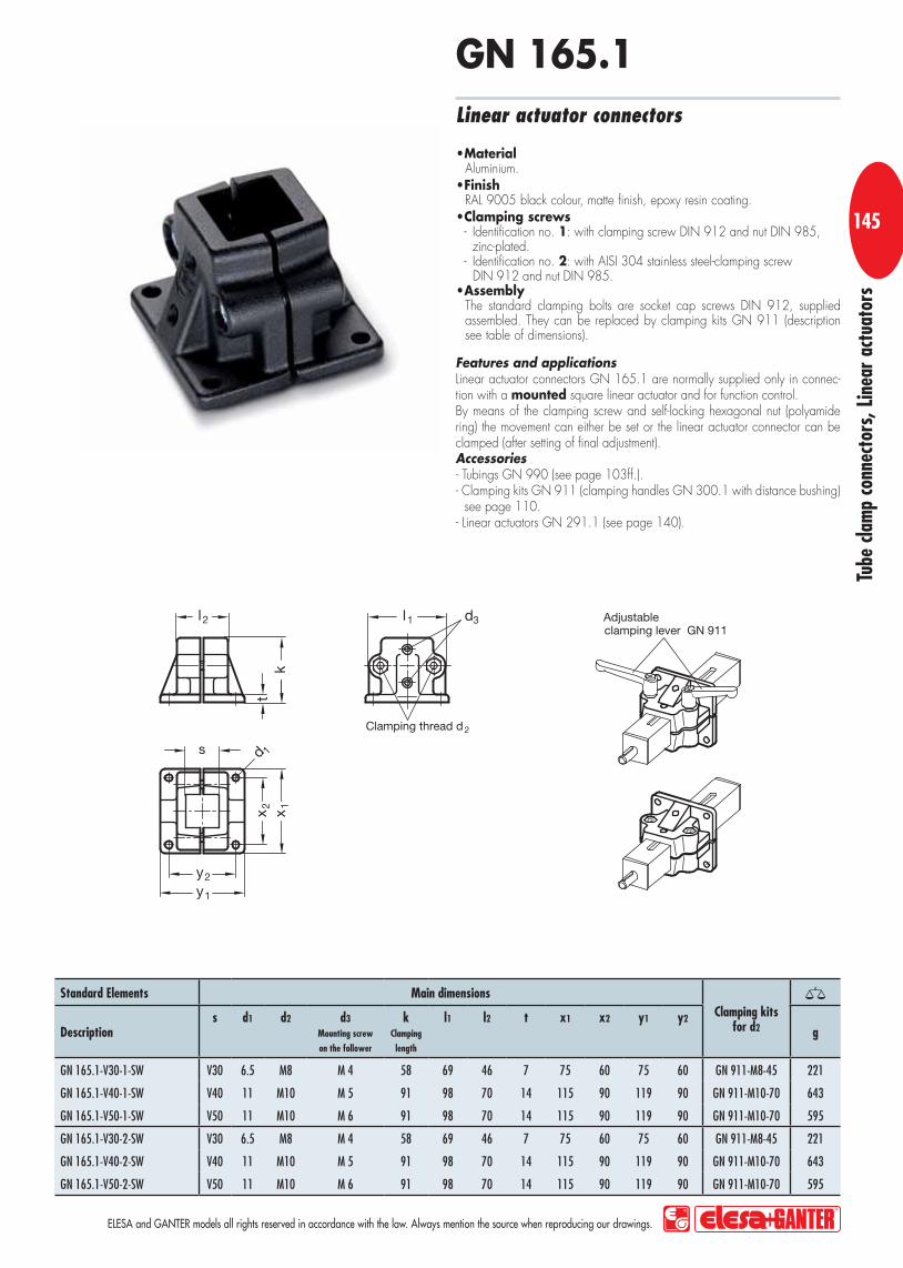
Tube
cla
mp
conn
ecto
rs, L
inea
r ac
tuat
ors
ELESA and GANTER models all rights reserved in accordance with the law. Always mention the source when reproducing our drawings.
145
Features and applicationsLinear actuator connectors GN 165.1 are normally supplied only in connec-tion with a mounted square linear actuator and for function control.By means of the clamping screw and self-locking hexagonal nut (polyamide ring) the movement can either be set or the linear actuator connector can be clamped (after setting of final adjustment).Accessories- Tubings GN 990 (see page 103ff.).- Clamping kits GN 911 (clamping handles GN 300.1 with distance bushing)
see page 110.- Linear actuators GN 291.1 (see page 140).
MaterialAluminium.FinishRAL 9005 black colour, matte finish, epoxy resin coating.Clamping screws- Identification no. 1: with clamping screw DIN 912 and nut DIN 985,
zinc-plated.- Identification no. 2: with AISI 304 stainless steel-clamping screw
DIN 912 and nut DIN 985.AssemblyThe standard clamping bolts are socket cap screws DIN 912, supplied assembled. They can be replaced by clamping kits GN 911 (description see table of dimensions).
Linear actuator connectors
GN 165.1
Standard Elements Main dimensions
Clamping kitsfor d2Description
s
d1
d2
d3 Mounting screw
on the follower
k Clamping
length
l1
l2
t
x1
x2
y1
y2 g
GN 165.1-V30-1-SW V30 6.5 M8 M 4 58 69 46 7 75 60 75 60 GN 911-M8-45 221
GN 165.1-V40-1-SW V40 11 M10 M 5 91 98 70 14 115 90 119 90 GN 911-M10-70 643
GN 165.1-V50-1-SW V50 11 M10 M 6 91 98 70 14 115 90 119 90 GN 911-M10-70 595
GN 165.1-V30-2-SW V30 6.5 M8 M 4 58 69 46 7 75 60 75 60 GN 911-M8-45 221
GN 165.1-V40-2-SW V40 11 M10 M 5 91 98 70 14 115 90 119 90 GN 911-M10-70 643
GN 165.1-V50-2-SW V50 11 M10 M 6 91 98 70 14 115 90 119 90 GN 911-M10-70 595

1
Tube
cla
mp
conn
ecto
rs, L
inea
r ac
tuat
ors
ELESA and GANTER models all rights reserved in accordance with the law. Always mention the source when reproducing our drawings.
146146
Linear actuators GN 291 (see page 113) with position indicators DD52R Handwheel VAD.I (see main catalogue page 484ff.) with position indicators GA11 (see main catalogue page 467) and linear actuator connectors GN 132.1 (see main catalogue page 124ff.) Square linear actuator connectors GN 291.1 (page 140ff.) and linear actuator connectors GN 147.1 (page 143)

Tube
cla
mp
conn
ecto
rs, L
inea
r ac
tuat
ors
ELESA and GANTER models all rights reserved in accordance with the law. Always mention the source when reproducing our drawings.
147
Handwheel for linear actuators Ø 18
MaterialCast aluminium.FinishRAL 9005 black colour, matte finish, epoxy resin coating.AssemblyHub with H7 reamed hole with keyway in compliance with DIN 6885/1 P9 tolerance.For fixing handwheels GN 923.18 on shafts by a grub screw see technical data page A2.Revolving handleType GN 798 polyamide based (PA) technopolymer, black colour, matte finish. Resistant to solvents, oils, greases and other chemical agents. The two-volume special design of the handle provides the operator’s hand with a safe and ergonomic grip when turning the handwheel.
GN 923.18
Accessories- Drive units GN 391 (see page 157ff.).- Transfer units GN 391 (see page 157ff.).- Linear actuators GN 291 (see page 113).- Linear actuators GN 292 (see page 116).
Standard Elements Main dimensions Bore Handle
Description d1 l2 b h d3 d4 d2 H7 l1 Ø g
GN 923.18-80-K6-R 80 26 13 7 26 17 6 16 16 150

1
Tube
cla
mp
conn
ecto
rs, L
inea
r ac
tuat
ors
ELESA and GANTER models all rights reserved in accordance with the law. Always mention the source when reproducing our drawings.
148148
MaterialCast aluminium.FinishRAL 9005 black colour, matte finish, epoxy resin coating.AssemblyHub with H7 reamed hole with keyway in compliance with DIN 6885/1 P9 tolerance.For fixing handwheels GN 923.30 on shafts by a grub screw see technical data page A2.Revolving handleType GN 798 polyamide based (PA) technopolymer, black colour, matte finish. Resistant to solvents, oils, greases and other chemical agents. The two-volume special design of the handle provides the operator’s hand with a safe and ergonomic grip when turning the handwheel.
Handwheel for linear actuators Ø 30
GN 923.30
Accessories- Drive units GN 391 (see page 157ff.).- Transfer units GN 391 (see page 157ff.).- Linear actuators GN 291 to GN 293 (see page 113ff.).- Square linear actuators GN 291.1 (see page 140).
Standard Elements Main dimensions Bore Handle
Description d1 l2 b h d3 d4 d2 H7 l1 Ø g
GN 923.30-100-K8-R 100 30 14 9.5 28 22 8 17 18 190

Tube
cla
mp
conn
ecto
rs, L
inea
r ac
tuat
ors
ELESA and GANTER models all rights reserved in accordance with the law. Always mention the source when reproducing our drawings.
149
Handwheel for linear actuators Ø 40
MaterialCast aluminium.FinishRAL 9005 black colour, matte finish, epoxy resin coating.AssemblyHub with H7 reamed hole with keyway in compliance with DIN 6885/1 P9 tolerance.For fixing handwheels GN 923.40 on shafts by a grub screw see technical data page A2.Revolving handleType GN 798 polyamide based (PA) technopolymer, black colour, matte finish. Resistant to solvents, oils, greases and other chemical agents. The two-volume special design of the handle provides the operator’s hand with a safe and ergonomic grip when turning the handwheel.
GN 923.40
Accessories- Drive units GN 391 (see page 157ff.).- Transfer units GN 391 (see page 157ff.).- Linear actuators GN 291 to GN 293 (see page 113ff.).- Square linear actuators GN 291.1 (see page 140).
Standard Elements Main dimensions Bore Handle
Description d1 l2 b h d3 d4 d2 H7 l1 Ø g
GN 923.40-100-K12-R 100 30 14 9.5 28 22 12 17 18 190

1
Tube
cla
mp
conn
ecto
rs, L
inea
r ac
tuat
ors
ELESA and GANTER models all rights reserved in accordance with the law. Always mention the source when reproducing our drawings.
150150
MaterialCast aluminium.FinishRAL 9005 black colour, matte finish, epoxy resin coating.AssemblyHub with H7 reamed hole with keyway in compliance withDIN 6885/1 P9 tolerance.For fixing handwheels GN 924.40 on shafts by a grub screw see technical data page A2.Revolving handleType GN 798 polyamide based (PA) technopolymer, black colour, matte finish. Resistant to solvents, oils, greases and other chemical agents. The two-volume special design of the handle provides the operator’s hand with a safe and ergonomic grip when turning the handwheel.
Handwheel for linear actuators Ø 40
GN 924.40
Accessories- Drive units GN 391 (see page 157ff.).- Transfer units GN 391 (see page 157ff.).- Linear actuators GN 291 to GN 293 (see page 113ff.).- Square linear actuators GN 291.1 (see page 140).
Standard Elements Main dimensions Bore Handle
Description d1 l2 b h d3 d4 d2 H7 l1 Ø g
GN 924.40-125-K12-R 125 33,5 15 11 31 23 12 18 22 400
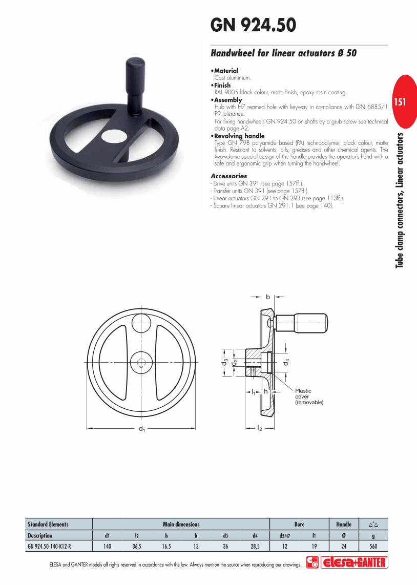
Tube
cla
mp
conn
ecto
rs, L
inea
r ac
tuat
ors
ELESA and GANTER models all rights reserved in accordance with the law. Always mention the source when reproducing our drawings.
151
Handwheel for linear actuators Ø 50
MaterialCast aluminium.FinishRAL 9005 black colour, matte finish, epoxy resin coating.AssemblyHub with H7 reamed hole with keyway in compliance with DIN 6885/1 P9 tolerance.For fixing handwheels GN 924.50 on shafts by a grub screw see technical data page A2.Revolving handleType GN 798 polyamide based (PA) technopolymer, black colour, matte finish. Resistant to solvents, oils, greases and other chemical agents. The two-volume special design of the handle provides the operator’s hand with a safe and ergonomic grip when turning the handwheel.
GN 924.50
Accessories- Drive units GN 391 (see page 157ff.).- Transfer units GN 391 (see page 157ff.).- Linear actuators GN 291 to GN 293 (see page 113ff.).- Square linear actuators GN 291.1 (see page 140).
Standard Elements Main dimensions Bore Handle
Description d1 l2 b h d3 d4 d2 H7 l1 Ø g
GN 924.50-140-K12-R 140 36,5 16.5 13 36 28,5 12 19 24 560

1
Tube
cla
mp
conn
ecto
rs, L
inea
r ac
tuat
ors
ELESA and GANTER models all rights reserved in accordance with the law. Always mention the source when reproducing our drawings.
152152
MaterialCast aluminium.FinishRAL 9005 black colour, matte finish, epoxy resin coating.AssemblyHub with H7 reamed hole with keyway in compliance with DIN 6885/1 P9 tolerance.For fixing handwheels GN 924.60 on shafts by a grub screw see technical data page A2.Revolving handleType GN 798 polyamide based (PA) technopolymer, black colour, matte finish. Resistant to solvents, oils, greases and other chemical agents. The two-volume special design of the handle provides the operator’s hand with a safe and ergonomic grip when turning the handwheel.
Handwheel for linear actuators Ø 60
GN 924.60
AccessoriesLinear actuators GN 291 to GN 293 (see page 113ff.).
Standard Elements Main dimensions Bore Handle
Description d1 l2 b h d3 d4 d2 H7 l1 Ø g
GN 924.60-160-K14-R 160 39,5 18 14,5 36 28,5 14 20 24 560

Tube
cla
mp
conn
ecto
rs, L
inea
r ac
tuat
ors
ELESA and GANTER models all rights reserved in accordance with the law. Always mention the source when reproducing our drawings.
153
Features and applicationsWith the installation kits GN 295 the linear actuators can be fitted with a position indicator.Retrofitting is possible. Remove the wheel, mount the kit and put the wheel back in place. For linear actuator units Ø 60, the plastic cover on the attachment side must be removed before assembly.As a rule a counter is chosen which matches the pitch of the trapeze thread on the lead spindle to show the read-out required per complete revolution.Accessories- Position indicators GN DD51 (see main cataogue page 488).- Position indicators GN DD52R (see main cataogue page 494). - Linear actuators GN 291 to GN 293 (see page 113ff.).Special executions on request (For sufficient quantities)Position indicators GA11/GA12 (see main cataogue page 467) and the necessary special handwheels.
Adapter shaftSteel, blackended.Torque limiting contact blockAluminium, black anodised.AssemblyAn installation kit comprises an adaptor shaft and a torque limiting contact block.
Installation kits
GN 295
Standard Elements Main dimensionsFor position indicatorsDescription
d1 Ø Linear actuator
d2 H7 / f7 b d3 l1 l2 l3 r1 r2 s g
GN 295-18-6 18 6 35 14 30 16 4.5 24.5 17.5 8 DD51 50
GN 295-30-8 30 8 35 14 35 15 - 24.5 17.5 10 DD51 60
GN 295-40-12 40 12 47 20 40 16 - 32 24.5 10 DD52R 120
GN 295-50-12 50 12 58 20 40 17 - 32 29 10 DD52R 118
GN 295-60-14 60 14 - 20 39 18 - - 32 7 DD52R -

1
Tube
cla
mp
conn
ecto
rs, L
inea
r ac
tuat
ors
ELESA and GANTER models all rights reserved in accordance with the law. Always mention the source when reproducing our drawings.
154154
Features and applicationsThe longitudinal scales GN 299 of Forms A and B are normally used in connection with the linear actuator units GN 291 and GN 291.1, the scales of Forms C and D are normally used for the linear actuator units GN 292 and GN 293.
SpecificationThe longitudinal scales (for standard travel lengths l1 of the linear actuator) are engraved by precision laser.AssemblyLongitudinal scales have to be ordered together with the linear actuators.
Longitudinal scales
GN 299

Tube
cla
mp
conn
ecto
rs, L
inea
r ac
tuat
ors
ELESA and GANTER models all rights reserved in accordance with the law. Always mention the source when reproducing our drawings.
155
Standard Elements Main dimensions
Descriptiond0
Ø Linear actuator
l1 Travel (Standard lenghts)
l2 l3 z Scale length or highest figure
GN 299-18-65-A-* 18 65 82.5 147.5 90
GN 299-18-165-A-* 18 165 82.5 247.5 190
GN 299-18-265-A-* 18 265 82.5 347.5 290
GN 299-30-100-A-* 30 100 122.5 222.5 120
GN 299-30-150-A-* 30 150 122.5 272.5 170
GN 299-30-200-A-* 30 200 122.5 322.5 220
GN 299-30-300-A-* 30 300 122.5 422.5 320
GN 299-40-70-A-* 40 70 142.5 217.5 90
GN 299-40-170-A-* 40 170 142.5 317.5 190
GN 299-40-220-A-* 40 220 142.5 367.5 240
GN 299-40-270-A-* 40 270 142.5 417.5 290
GN 299-40-320-A-* 40 320 142.5 467.5 340
GN 299-50-65-A-* 50 65 147.5 217.5 90
GN 299-50-115-A-* 50 115 147.5 267.5 140
GN 299-50-215-A-* 50 215 147.5 367.5 240
GN 299-50-265-A-* 50 265 147.5 417.5 290
GN 299-50-315-A-* 50 315 147.5 467.5 340
GN 299-60-220-A-* 60 220 182.5 402.5 240
GN 299-60-720-A-* 60 720 182.5 902.5 740
GN 299-18-65-B-* 18 65 82.5 147.5 90
GN 299-18-165-B-* 18 165 82.5 247.5 190
GN 299-18-265-B-* 18 265 82.5 347.5 290
GN 299-30-100-B-* 30 100 122.5 222.5 120
GN 299-30-150-B-* 30 150 122.5 272.5 170
GN 299-30-200-B-* 30 200 122.5 322.5 220
GN 299-30-300-B-* 30 300 122.5 422.5 320
GN 299-40-70-B-* 40 70 142.5 217.5 90
GN 299-40-170-B-* 40 170 142.5 317.5 190
GN 299-40-220-B-* 40 220 142.5 367.5 240
GN 299-40-270-B-* 40 270 142.5 417.5 290
GN 299-40-320-B-* 40 320 142.5 467.5 340
GN 299-50-65-B-* 50 65 147.5 217.5 90
GN 299-50-115-B-* 50 115 147.5 267.5 140
GN 299-50-215-B-* 50 215 147.5 367.5 240
GN 299-50-265-B-* 50 265 147.5 417.5 290
GN 299-50-315-B-* 50 315 147.5 467.5 340
GN 299-60-220-B-* 60 220 182.5 402.5 240
GN 299-60-720-B-* 60 720 182.5 902.5 740
* Complete the description of the standard item needed by adding the identification number of the scale (see drawing).

1
Tube
cla
mp
conn
ecto
rs, L
inea
r ac
tuat
ors
ELESA and GANTER models all rights reserved in accordance with the law. Always mention the source when reproducing our drawings.
156156
Standard Elements Main dimensions
Descriptiond0
Ø Linear actuator
l1 Travel (Standard lenghts)
l2 l3 z Scale length or highest figure
GN 299-18-65-C-* 18 65 82.5 147.5 90
GN 299-18-165-C-* 18 165 82.5 247.5 190
GN 299-18-265-C-* 18 265 82.5 347.5 290
GN 299-30-100-C-* 30 100 122.5 222.5 120
GN 299-30-150-C-* 30 150 122.5 272.5 170
GN 299-30-200-C-* 30 200 122.5 322.5 220
GN 299-30-300-C-* 30 300 122.5 422.5 320
GN 299-40-70-C-* 40 70 142.5 217.5 90
GN 299-40-170-C-* 40 170 142.5 317.5 190
GN 299-40-220-C-* 40 220 142.5 367.5 240
GN 299-40-270-C-* 40 270 142.5 417.5 290
GN 299-40-320-C-* 40 320 142.5 467.5 340
GN 299-50-65-C-* 50 65 147.5 217.5 90
GN 299-50-115-C-* 50 115 147.5 267.5 140
GN 299-50-215-C-* 50 215 147.5 367.5 240
GN 299-50-265-C-* 50 265 147.5 417.5 290
GN 299-50-315-C-* 50 315 147.5 467.5 340
GN 299-60-220-C-* 60 220 182.5 402.5 240
GN 299-60-720-C-* 60 720 182.5 902.5 740
GN 299-18-65-D-* 18 65 82.5 147.5 90
GN 299-18-165-D-* 18 165 82.5 247.5 190
GN 299-18-265-D-* 18 265 82.5 347.5 290
GN 299-30-100-D-* 30 100 122.5 222.5 120
GN 299-30-150-D-* 30 150 122.5 272.5 170
GN 299-30-200-D-* 30 200 122.5 322.5 220
GN 299-30-300-D-* 30 300 122.5 422.5 320
GN 299-40-70-D-* 40 70 142.5 217.5 90
GN 299-40-170-D-* 40 170 142.5 317.5 190
GN 299-40-220-D-* 40 220 142.5 367.5 240
GN 299-40-270-D-* 40 270 142.5 417.5 290
GN 299-40-320-D-* 40 320 142.5 467.5 340
GN 299-50-65-D-* 50 65 147.5 217.5 90
GN 299-50-115-D-* 50 115 147.5 267.5 140
GN 299-50-215-D-* 50 215 147.5 367.5 240
GN 299-50-265-D-* 50 265 147.5 417.5 290
GN 299-50-315-D-* 50 315 147.5 467.5 340
GN 299-60-220-D-* 60 220 182.5 402.5 240
GN 299-60-720-D-* 60 720 182.5 902.5 740
* Complete the description of the standard item needed by adding the identification number of the scale (see drawing).

Tube
cla
mp
conn
ecto
rs, L
inea
r ac
tuat
ors
ELESA and GANTER models all rights reserved in accordance with the law. Always mention the source when reproducing our drawings.
157
Features and applicationsTransfer units GN 391 are normally used in connection with linear actuators (GN 291, GN 292, GN 293). They are designed to translate the rotary mo-vement for operating the linear actuators to another point or position.The transfer unit in the standard length l1 is a special design: it is designed to turn the operating axis for the linear actuators (handwheel) by 90° together with an angular gear drive.
As in linear actuators, digital position indicators can be fitted.Accessories- Housings GN 298 (see page 160).- Bevel gear wheels GN 297 (see page 159).- Position indicators GN DD51 (see main cataogue page 488).- Position indicators GN DD52R (see main cataogue page 494). - Installation kits for linear actuators GN 295 (see page 153).Special executions on request (For sufficient quantities)Transfer units GN 391 according to customer's requirement (e.g. GN 391-50-500-SCR)
Guide tubePrecision steel tube, chrome-plated SCR, DIN 2391.SpindleSteel thust ball bearings.End capsPlastic.AssemblyBevel-gear wheels / handwheels, tube clamp connectors and accessoires are to be ordered separately.
Drive units
GN 391
Standard Elements Main dimensions
Descriptiond1
l1 Standard lengths of the drive units
l1 Standard lengths
of the transfer units
d2 f7
l2 g
GN 391-18-47-SCR 18 47 * 6 16 60
GN 391-30-60-SCR 30 60 * 8 16 180
GN 391-40-93-SCRI 40 93 * 12 17 500
GN 391-50-93-SCR 50 93 * 12 18 780
* Length according to customer's requirement.

1
Tube
cla
mp
conn
ecto
rs, L
inea
r ac
tuat
ors
ELESA and GANTER models all rights reserved in accordance with the law. Always mention the source when reproducing our drawings.
158158
Features and applicationsTransfer units GN 391-NI are normally used in connection with linear actuators (GN 291, GN 292, GN 293). They are designed to translate the rotary mo-vement for operating the linear actuators to another point or position.The transfer unit in the standard length l1 is a special design: it is designed to turn the operating axis for the linear actuators (handwheel) by 90° together with an angular gear drive.
As in linear actuators, digital position indicators can be fitted.Accessories- Housings GN 298 (see page 160).- Bevel gear wheels GN 297 (see page 159).- Position indicators GN DD51 (see main cataogue page 488).- Position indicators GN DD52R (see main cataogue page 494). - Installation kits for linear actuators GN 295 (see page 153).Special executions on request (For sufficient quantities)Transfer units GN 391 according to customer's requirement (e.g. GN 391-50-500-NI)
Guide tube Precision AISI 301stainless steel tube, DIN 2462.SpindleStainless steel thrust ball bearings.End capsPlastic.AssemblyBevel-gear wheels / handwheels, tube clamp connectors and accessoires are to be ordered separately.
Drive units
GN 391-NI
Standard Elements Main dimensions
Descriptiond1
l1 Standard lengths of the drive units
l1 Standard lengths
of the transfer units
d2 f7
l2 g
GN 391-18-47-NI 18 47 * 6 16 60
GN 391-30-60-NI 30 60 * 8 16 180
GN 391-40-93-NI 40 93 * 12 17 500
GN 391-50-93-NI 50 93 * 12 18 780
* Length according to customer's requirement.

Tube
cla
mp
conn
ecto
rs, L
inea
r ac
tuat
ors
ELESA and GANTER models all rights reserved in accordance with the law. Always mention the source when reproducing our drawings.
159Features and applicationsBevel-gear wheels GN 297 are used for angular / T-gears in connection with linear actuators / transfers units and housings GN 298.wo bevel-gear wheels are required for an angular gear, three for a T-gear. The transmission ratio is always 1:1.Accessories- Housings GN 298 (see page 160).- Drive units GN 391 (see page 157ff.).- Transfer units GN 391 (see page 157ff.).- Linear actuators GN 291 to GN 293 (see page 113ff.).
MaterialSteel blackened, teeth milled.
Bevel gear wheels
GN 297
Standard Elements Main dimensions
Descriptiond0
Ø Linear actuator
Ø Transfer unit GN 391
d1
d2 H7
Bore
with keyway
b
d3
Length l
g
GN 297-17-K6 18 17 K6 2 M4 11 9
GN 297-26-K8 30 26 K8 2 M6 19 36
GN 297-34-K12 40 34 K12 4 M6 23.5 59
GN 297-40-K12 50 40 K12 4 M6 24 85

1
Tube
cla
mp
conn
ecto
rs, L
inea
r ac
tuat
ors
ELESA and GANTER models all rights reserved in accordance with the law. Always mention the source when reproducing our drawings.
160160
Features and applicationsHousings GN 298 for angular gears / T-gears are used in connection with bevel-gear wheels GN 297 and linear actuators / transfer units: the angular gears / T-gears are designed to deflect the rotary movement of a linear actuator / transfer unit by 90°.Accessories- Bevel gear wheels GN 297 (see page 159).- Drive units GN 391 (see page 157ff.).- Transfer units GN 391 (see page 157ff.).- Linear actuators GN 291 to GN 293 (see page 113ff.).
HousingAluminium gravity die-cast.Clamping screwsStainless SteelFinishRAL 9005 black, matte finish, epoxy resin coating.Types- Type W: for angular gears.- Type T: for T-gears.
Housings
GN 298
Standard Elements Main dimensions
Descriptions
d Bore for Linear actuator
Transfer unit
l1
l2
g
GN 298-28-B18-W-SW 28 B18 60 90 107
GN 298-40-B30-W-SW 40 B30 84 126 219
GN 298-50-B40-W-SW 50 B40 108 162 434
GN 298-60-B50-W-SW 60 B50 128 190 692
GN 298-28-B18-T-SW 28 B18 60 90 139
GN 298-40-B30-T-SW 40 B30 84 126 280
GN 298-50-B40-T-SW 50 B40 108 162 542
GN 298-60-B50-T-SW 60 B50 128 190 851

Tube
cla
mp
conn
ecto
rs, L
inea
r ac
tuat
ors
ELESA and GANTER models all rights reserved in accordance with the law. Always mention the source when reproducing our drawings.
161
d1
Ø Linear actuator
Ø Transfer unit GN 391
m1
m2
Bevel gear wheel
Housing
Length of the transfer unit
18 19.5 22 GN 297-17-K6 GN 298-28-B18-W/T-SW
l1 = A - 2 x m130 26 35 GN 297-26-K8 GN 298-40-B30-W/T-SW
40 26 44 GN 297-34-K12 GN 298-50-B40-W/T-SW
50 33.5 56 GN 297-40-K12 GN 298-60-B50-W/T-SW
Assembly of linear actuators / transfer units with bevel gear wheels in housings GN 298
Bevel gear wheels and linear actuator/transfer unit assembled.

1
Tube
cla
mp
conn
ecto
rs, L
inea
r ac
tuat
ors
ELESA and GANTER models all rights reserved in accordance with the law. Always mention the source when reproducing our drawings.
162162
GN 298-W
GN 132.1
GN 924.40
GN 391
GN 298-W
GN 391
GN 146
GN 291
GN 132.1
GN 291
GN 391
GN 298-W
GN 391
GN 146.1
GN 291
GN 163
GN 163
GN 291
GN 298-T
GN 924.40
Two parallel sliding linear actuators are connected with a transfer unit GN 391.
The angular housing GN 298-W including the bevel gear wheels GN 297 and another transfer unit GN 391 connect the hand-wheel with the system. The handwheel is placed in a rectangular position to the moving axes.
Two linear actuators GN 291 are connected with a transfer unit GN 391 and so two flanged linear actuator connectors GN 146.1 will be moved in parallel.
The T- and angular gears GN 298-T/-W including the assembled bevel gear wheels GN 297 and another transfer unit GN 391 connect the handwheel with the system. The handwheel is (placed) in a parallel position to the moving axes.

Technical data

Tech
nical
dat
a
2A
ELESA and GANTER models all rights reserved in accordance with the law. Always mention the source when reproducing our drawings.
Orientation of keyways DIN 6885/1 KEYWAYS
d b P9/JS9Hub keyway
b P9/N9Shaft-keyway
h t2 t4
from 6 to 8 2 2 2 1 +0.1 1.2 +0.1
over 8 to 10 3 3 3 1.4 +0.1 1.8 +0.1
over 10 to 12 4 4 4 1.8 +0.1 2.5 +0.1
over 12 to 17 5 5 5 2.3 +0.1 3 +0.1
over 17 to 22 6 6 6 2.8 +0.1 3.5 +0.1
over 22 to 30 8 8 7 3.3 +0.2 4 +0.2
over 30 to 38 10 10 8 3.3 +0.2 5 +0.2
over 38 to 44 12 12 8 3.3 +0.2 5 +0.2
over 44 to 50 14 14 9 3.8 +0.2 5.5 +0.2
DIN 6885/2 KEYWAYS
d b P9/JS9Hub keyway
b P9/N9Shaft-keyway
h t2 t4
from 10 to 12 4 4 4 1.1 +0.1 3 +0.1
over 12 to 17 5 5 5 1.3 +0.1 3.8 +0.1
over 17 to 22 6 6 6 1.7 +0.1 4.4 +0.1
over 22 to 30 8 8 7 1.7 +0.2 5.4 +0.2
over 30 to 38 10 10 8 2.1 +0.2 6 +0.2
over 38 to 44 12 12 8 2.1 +0.2 6 +0.2
over 44 to 50 14 14 9 2.6 +0.2 6.5 +0.2
Width of keyway:P9 tight fit (standard design)JS or N9 loose fit (requires agreement in writing)
Width of keyway:P9 tight fit (standard design)JS or N9 loose fit (requires agreement in writing)
Technical Data

Tech
nical
dat
a
3A
ELESA and GANTER models all rights reserved in accordance with the law. Always mention the source when reproducing our drawings.
ISO-Fundamental tolerance series DIN ISO 286Tol. (μm) Nominal sizes
Grades - >3 >6 >10 >18 >30 >50 >80 >120 >180 >250 >315 >400
IT ... 3 ... 6 ... 10 ... 18 ... 30 ... 50 ... 80 ... 120 ... 180 ... 250 ... 315 ... 400 ... 500
01 0.3 0.4 0.4 0.5 0.6 0.6 0.8 1 1.2 2 2.5 3 4
0 0.5 0.6 0.6 0.8 1 1 1.2 1.5 2 3 4 5 6
1 0.8 1 1 1.2 1.5 1.5 2 2.5 3.5 4.5 6 7 8
2 1.2 1.5 1.5 2 2.5 2.5 3 4 5 7 8 9 10
3 2 2.5 2.5 3 4 4 5 6 8 10 12 13 15
4 3 4 4 5 6 7 8 10 12 14 16 18 20
5 4 5 6 8 9 11 13 15 18 20 23 25 27
6 6 8 9 11 13 16 19 22 25 29 32 36 40
7 10 12 15 18 21 25 30 35 40 46 52 57 63
8 14 18 22 27 33 39 46 54 63 72 81 89 97
9 25 30 36 43 52 62 74 87 100 115 130 140 155
10 40 48 58 70 84 100 120 140 160 185 210 230 250
11 60 75 90 110 130 160 190 220 250 290 320 360 400
12 100 120 150 180 210 250 300 350 400 460 520 570 630
13 140 180 220 270 330 390 460 540 630 720 810 890 970
14 250 300 360 430 520 620 740 870 1000 1150 1300 1400 1550
15 400 480 580 700 840 1000 1200 1400 1600 1850 2100 2300 2500
16 600 750 900 1100 1300 160 1900 2200 2500 2900 3200 3600 4000
17 1000 1200 1500 1800 2100 2500 3000 3500 4000 4600 5200 5700 6300
18 1400 1800 2200 2700 3300 3900 4600 5400 6300 7200 8100 8900 9700
Tol. (μm) Nominal sizesclasses ... >3 >6 >10 >18 >30 >50 >80 >120 >180
for bore ... 3 ... 6 ...10 ...18 ...30 ...50 ...80 ...120 ...180 ...250D9 +45 +60 +76 +93 +117 +142 +174 +207 +245 +285
+20 +30 +40 +50 +65 +80 +100 +120 +145 +170D12 +120 +150 +190 +230 +275 +330 +400 +470 +545 +630
+20 +30 +40 +50 +65 +80 +100 +120 +145 +170E8 +28 +38 +47 +59 +73 +89 +106 +126 +148 +172
+14 +20 +25 +32 +40 +50 +60 +72 +85 +100G6 +8 +12 +14 +17 +20 +25 +29 +34 +39 +44
+2 +4 +5 +6 +7 +9 +10 +12 +14 +15G7 +12 +16 +20 +24 +28 +34 +40 +47 +54 +61
+2 +4 +5 +6 +7 +9 +10 +12 +14 +15H7 +10 +12 +15 +18 +21 +25 +30 +35 +40 +46
0 0 0 0 0 0 0 0 0 0H8 +14 +18 +22 +27 +33 +39 +46 +54 +63 +72
0 0 0 0 0 0 0 0 0 0H9 +25 +30 +36 +43 +52 +62 +74 +87 +100 +115
0 0 0 0 0 0 0 0 0H11 +60 +75 +90 +110 +130 +160 +190 +220 +250 +290
0 0 0 0 0 0 0 0 0H12 +100 +120 +150 +180 +210 +250 +300 +350 +400 +460
0 0 0 0 0 0 0 0 0 0H13 +140 +180 +220 +270 +330 +390 +460 +540 +630 +720
0 0 0 0 0 0 0 0 0 0H14 +250 +300 +360 +430 +520 +620 +740 +870 +1000 +1150
0 0 0 0 0 0 0 0 0 0JS9 ±12.5 ±15 ±18 ±21.5 ±26 ±31 ±37 ±43.5 ±50 ±57.5N9 -4 0 0 0 0 0 0 0 0 0
-29 -30 -36 -43 -52 -62 -74 -87 -100 -115P9 -6 -12 -15 -18 -22 -26 -32 -37 -43 -50
-31 -42 -51 -61 -74 -88 -106 -124 -143 -165for shaft
f7 -6 -10 -13 -16 -20 -25 -30 -36 -43 -50-16 -22 -28 -34 -41 -50 -60 -71 -83 -96
h6 0 0 0 0 0 0 0 0 0 0-6 -8 -9 -11 -13 -16 -19 -22 -25 -29
h7 0 0 0 0 0 0 0 0 0 0-10 -12 -15 -18 -21 -25 -30 -35 -40 -46
h8 0 0 0 0 0 0 0 0 0 0-14 -18 -22 -27 -33 -39 -46 -54 -63 -72
h9 0 0 0 0 0 0 0 0 0 0-25 -30 -36 -43 -52 -62 -74 -87 -100 -115
h11 0 0 0 0 0 0 0 0 0 0-60 -75 -90 -110 -130 -160 -190 -220 -250 -290
h13 0 0 0 0 0 0 0 0 0 0-140 -180 -220 -270 -330 -390 -460 -540 -630 -720
h14 0 0 0 0 0 0 0 0 0 0-250 -300 -360 -430 -520 -620 -740 -870 -1000 -1150
js14 ±125 ±150 ±180 ±215 ±260 ±310 ±370 ±435 ±500 ±575n6 +10 +16 +19 +23 +28 +33 +39 +45 +52 +60
+4 +8 +10 +12 +15 +17 +20 +23 +27 +31p6 +12 +20 +24 +29 +35 +42 +51 +59 +68 +79
+6 +12 +15 +18 +22 +26 +32 +37 +43 +50
This ISO Standard represents the basic for a system
of nominal dimensions and sizes whereby the table
mirrors the calculated values of basic tolerances
relating to basic dimensions.
The use of this table is limited to smooth circular
cylindrical workpieces or such with two parallel
fitting planes or contact areas.
The values attribuited to an ISO tolerance grade
(IT) specify the tolerance value and hence the
tolerance area. With ascending numbers, the size
of the tolerance increases.
For identification purpose of the position of the
tolerance area in relation to the nominal dimension
(zero), the number chosen as tolerance grade IT is
preceeded by a letter.
Tolerance area H is the most common value for
bores. It specifies that the minimum dimension of
the bore corresponds to the nominal dimension.
The permissible maximum dimension corresponds
to the nominal dimension plus the IT tolerance.
Examples: bore 20 H7 = 20 +0.021/0 bore 8 H11 = 8 +0.090/0
min. dimens.: 20.000 min. dimens.: 8.000
max. dimens.: 20.021 min. dimens.: 8.090

Tech
nical
dat
a
4A
ELESA and GANTER models all rights reserved in accordance with the law. Always mention the source when reproducing our drawings.
PROPERTIES OF METAL MATERIALS
Description AISI 303 AISI 304+Cu AISI 304 AISI 316 AISI 316 LHC AISI 301 AISI 302 AISI CF-8
Designation in accordance withEN 10088-1-2-3EN 10283 (AISI CF-8)SINT C40 (AISI 316 LMC)
X 8 CrNiS 18-9 X 3 CrNiCu 18-9-4 X 5 CrNi 18-10 X 5 CrNiMo 17-12Sint C40
X 2 CrNiMo 17-12-2EN 100088-1;-2;-3
X10CrNi 18-8X 10 CrNi 18-09
EN 10283GX5CrNi 19-10
% components of alloy
C ≤ 0.10Si ≤ 1.0
Mn ≤ 2.0P ≤ 0.045
S ≤ 0.15 ÷ 0.35Cr 17.0 ÷ 19.0Ni 8.0 ÷ 10.0
C ≤ 0.04Si ≤ 1.0
Mn ≤ 2.0P ≤ 0.045S ≤ 0.030
Cr 17.0 ÷ 19.0Ni 8.5 ÷ 10.5
C ≤ 0.07Si ≤ 1.0
Mn ≤ 2.0P ≤ 0.045S ≤ 0.030
Cr 17.0 ÷ 19.5Ni 8.0 ÷ 10.5
C ≤ 0.08Si ≤ 1.0
Mn ≤ 2.0P ≤ 0.045S ≤ 0.030
Cr 16.0 ÷ 18.5Ni 10.0 ÷ 13.0
C ≤ 0.08Si ≤ 0.9
Mn ≤ 0.1Mo ≤ 2.0 ÷ 4.0Cr 16.0 ÷ 19.0Ni 10.0 ÷ 14.0
C ≤ 0.05 ÷ 0.15Si ≤ 2.0
Mn ≤ 2.0P ≤ 0.045S ≤ 0.015
Cr 16.0 ÷ 19.0Mo ≤ 0.8
Ni 6.0 ÷ 9.5
C ≤ 0.08Si ≤ 0.6
Mn ≤ 1.2Cr 18.0Ni 9.0
C ≤ 0.07Si ≤ 2.0Si ≤ 1.5
Mn ≤ 1.5P ≤ 0.04S ≤ 0.03
Cr 18.0 ÷ 20.0Ni 8.0 ÷ 11.0
Minimum load at breakageRm N/mm2 500 - 700 450 - 650 500 - 700 500 - 700 330 500 - 750 600 - 800 440 - 640
Yield point Rp 0.2 n/mm2 ≥ 190 ≥ 175 ≥ 190 ≥ 205 ≥ 250 ≥ 195 ≥ 210 ≥ 175
Machinability Very good Excellent Fair Fair - Poor Good Medium
Forgeability Poor Good Good Good - Good Poor -
Suitability for welding Poor Very good Excellent Good - Good Poor Good
Special features
Non-magnetic structure
Excellent for machining
on automatic machines
Non-magnetic structure
suitable for low temperatures
Non-magnetic structure
suitable for low temperatures may be used at up to
700 °C
Magnetic structuresuitable for low temperatures
Non-magnetic structure
Austenitic structureMagnetic structure
suitable for low temperatures
Antimagnetc, austenitic structure
Corrosion resistance
Fair Very good Good Excellent Medium Good Fair Good
Due to sulphur content,
use in environments containing acids
or chlorides should be avoided.
Resistant to corrosion in natural
environments:water, urban or country climates
with no significant concentrations of
chlorides, in the food industry.
Resistant to corrosion in natural
environments:water, urban or country climates
with no significant concentrations of
chlorides, in the food industry.
Resistant to corrosion also
in marine environments or wet environments and in the presence of
acids.
By virtue of its coarser porosity
the corrosion resistance is in
general reduced as compared with
stainless steel.Reservations especially in
acid and salty environment.
Corrosion resistant in a natural environment;
water, rural, urban and industrial atmosphere.
Corrosion resistant.Material is to a large extent comparable
with AISI 304
Main fields of applicationConstruction of
vehicles.Electronics.
Furniture finishings.
Food, chemical and pharmaceutical
industries. Agriculture. Construction of machines. Electronics.
Shipping. Furniture finishings
Food, chemical and pharmaceutical
industries. Agriculture. Construction
of vehicles and machines. Building. Furniture finishings.
Food and chemical industries.
Ship building and manufacture of components
for marine environments or use in highly corrosive
conditions.
Chemical, cellulose and paper industry.Paint, oil, soap and
textile industry.Daires. Breweries.
Springs for temperature up to
300 °C.Tools (knives).Sheet metal for
vehicles automotive industry. Chemical and food industry.
Used for the manufacture of
springs in various fields of application.
Food, beverage and packing industry.
Armatures. Pumps. Mixers.
STAINLESS STEELS
The characteristics described should be treated as guidelines only. No guarantee is made. The user is responsible for checking the exact operating conditions.

5A
ELESA and GANTER models all rights reserved in accordance with the law. Always mention the source when reproducing our drawings.
NOTES

Inde
x
SERIES PAGE SERIES PAGE
6A
Index
GN 131 10
GN 131-NI 11
GN 131.1 120
GN 131.1-NI 121
GN 131.2 122
GN 131.2-NI 123
GN 132 12
GN 132.1 124
GN 132.2 126
GN 133 14
GN 134 16
GN 134.1 144
GN 141 20
GN 145 22
GN 145-NI 23
GN 145.1 128
GN 145.1-NI 129
GN 146 24
GN 146.1 130
GN 146.3 26
GN 147 28
GN 147.1 143
GN 162 30
GN 162-NI 31
GN 162.1 131
GN 162.1-NI 132
GN 163 32
GN 163.1 133
GN 165 34
GN 165.1 145
GN 166 36
GN 167 38
GN 171 40
GN 191 44
GN 191-NI 45
GN 191.1 134
GN 191.1-NI 135
GN 192 46
GN 192.1 136
GN 193 48
GN 194 51
GN 195 54
GN 231 56
GN 241 58
GN 242 60
GN 271 63
GN 271.4 100
GN 272 64
GN 272.4 101
GN 273 65
GN 273.1 137
GN 273.4 102
GN 274 66
GN 274.1 138
GN 275 69
GN 276 70
GN 277 73
GN 278 74
GN 281 77
GN 282 80
GN 283 82
GN 284 84
GN 285 88
GN 286 90
GN 287 94
GN 288 96
GN 291 113
GN 291.1 140
GN 292 116
GN 293 117
GN 295 153
GN 297 159
GN 298 160
GN 299 154
GN 391 157
GN 391-NI 158
GN 911 110
GN 923.18 147
GN 923.30 148
GN 923.40 149
GN 924.40 150
GN 924.50 151
GN 924.60 152
GN 990 104
GN 990-NI 103
GN 991 106
GN 992 108

www.elesa-ganter.com
Tube Clamp ConnectorsLinear Actuators
TUBE
CLA
MP
CO
NN
ECTO
RS E
G02
11EN
- C
opyr
ight
© 2
011
ELES
A+
GA
NTE
R 01
/201
1
OTTO GANTER GmbH & Co.KGTriberger Straße 378120 Furtwangen GERMANYPhone: +49 7723 65 07 130Fax: +49 7723 65 07 [email protected]
ELESA S.p.A.Via Pompei 2920052 Monza (Milano) ITALYPhone: +39 039 28 11.1Fax: +39 039 83 63 [email protected]
Distributed by


![FnIO G-Series: GN-9481 / GN-9482 / GN-9483Spec] GN-9481_GN...Run-Time System Multiple PLC Tasks Program Languages IEC 61131-3 (LD, IL, ST, FBD, SFC) OPC-Server GN-9481 Not supporting](https://static.fdocuments.in/doc/165x107/5fcf359602c376594f0af992/fnio-g-series-gn-9481-gn-9482-gn-9483-spec-gn-9481gn-run-time-system-multiple.jpg)