TUBACERO INFORMATION - · PDF file1.0 MATERIALS FLOW AND OPERATIONS ... Later the process of...
51
TUBACERO INFORMATION Last Update: May 2011.
Transcript of TUBACERO INFORMATION - · PDF file1.0 MATERIALS FLOW AND OPERATIONS ... Later the process of...

IN
TUBACERO FORMATIONLast Update: May 2011.
TABLE OF CONTENTS
I. COMPANY PROFILE....................................................... 3 II. CERTIFICATES .............................................................. 5
1. ISO............................................................................................................................ 6 2. API 5L ...................................................................................................................... 7
III. LIST OF MAIN PROJECTS ........................................... 8 IV. PRODUCTION CAPACITY.......................................... 22 V. MILL PRODUCTION CAPABILITIES ........................... 23
MILL. NO. 1............................................................................................................... 23 MILL NO. 2................................................................................................................ 24 MILL NO. 3................................................................................................................ 25 CAPABILITIES PER PLANT ................................................................................... 26
VI. MANUFACTURING PROCESS................................... 27 1.0 MATERIALS FLOW AND OPERATIONS ....................................................... 28 2.0 DEFINITION ....................................................................................................... 29 3.0 CONTINUOUS FORMING................................................................................. 29 4.0 DOUBLE SUBMERGED ARC ........................................................................... 31 5.0 FINISHING .......................................................................................................... 35 6.0 COATING ............................................................................................................ 37
VII. QUALITY CONTROL PROCEDURE.......................... 39 I.- RAW MATERIAL PROCEDURE (PLATE AND COIL).................................... 40 II.- MECHANICAL PROPERTIES EVALUATION PROCEDURES..................... 41 III.- INSPECTION PROCEDURES .......................................................................... 43 IV.- PIPE CERTIFICATION ..................................................................................... 49 V.- CORRECTIVE ACTIONS .................................................................................. 50 VI.-INSPECTION AND TEST CONTROL .............................................................. 50 VII.- MEASURING AND TEST EQUIPMENT CONTROL ................................... 51

I. COMPANY PROFILE
TUBACERO is a privately owned, 100% Mexican company, with more than 60 years of experience and tradition, a leader in the manufacture of steel pipes. When TUBACERO began its operations, in 1943, its production was rolled and manually welded; as time went by, it was substituted for those manufactured by hydraulic press and automatic submerged arc welding (DSAW). Later the process of Continuous Formation and Electric Resistance Welding (ERW) were installed. At the present time, TUBACERO has five plants with a total installed annual capacity of 350,000 metric tons on a 439,961 square meter surface area where carbon steel pipes, are welded longitudinally in diameters of 6.625" to 150", and in wall thickness that range from 0.156" to 2.50". Our products are the best option for the Petroleum, Electrical, Mining and Construction Industries, as well as for the Hydraulic Sector, which conducts fluid, semi-solid and solids in diverse environmental conditions. They perfectly adapt to the ground configuration because of its distinguishing characteristics such as: security, impact resistance, static and dynamic charge resistance, ductility and durability. The concept of quality in TUBACERO has permitted the company to remain in the vanguard position in the manufacturing of steel pipe, guaranteeing excellent quality, delivery and service. This concept is based on TUBACERO´S Quality Assurance Program, which is active from the acquisition of the raw materials to the shipment and delivery of the finished product. This program is certified by international organizations such as API-Q1 and ISO-9000, which testify to the manufacturing and administrative performance of our company. Besides is certified as a reliable supplier by Pemex (Petroleos Mexicanos). Since its beginnings, TUBACERO has participated in international markets. Its products and services have been exported to different countries around the world, such as: Saudi Arabia, Argentina, Australia, Bangladesh, Bolivia, Canada, Chile, China, Colombia, Costa Rica, Ecuador, United States of America, Guatemala, Honduras, India,

Indonesia, Italy, Kuwait, Malaysia, Oman, Peru, Great Britain, Dominican Republic, Switzerland, Trinidad y Tobago, Turkey and Venezuela. Tubacero is represented commercially in many other countries in every continent. By 1993, TUBACERO established a pipe coating facility in Monterrey, in association with BREDERO SHAW MEXICO of Houston, Texas, U.S.A. where Fusion Bonded Epoxy, 3-layer Polyethylene, Polypropylene and Flow Efficiency Coating is applied to the pipe.

II. CERTIFICATES The concept of quality in Tubacero also is part of its way of living, because of this, Tubacero has become one of the manufacturers that produces the pipe according the specifications requested by the market. Quality is the main factor for us: in 1959 we received the license API 5L and presently we are part of the technical committee. In 1989 we got the certification of API Q1 issued by the American Petroluem Institute. In 1993 Tubacero was the first company in Latin America that received the ISO-9002 certification for its longitudinal welded process. Since 1st of July of 2002, we have the ISO-9001:2000 certification.
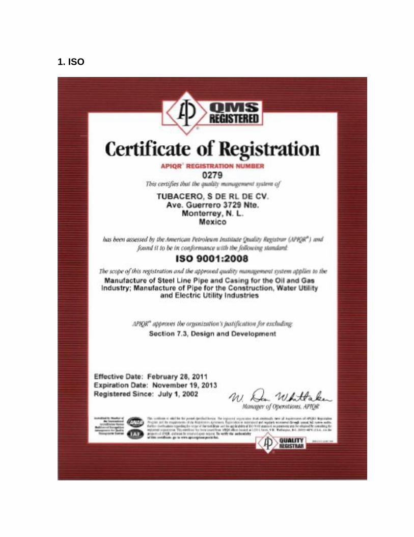
1. ISO

2. API 5L

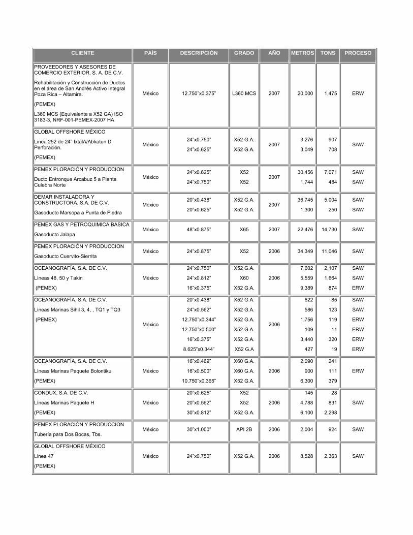
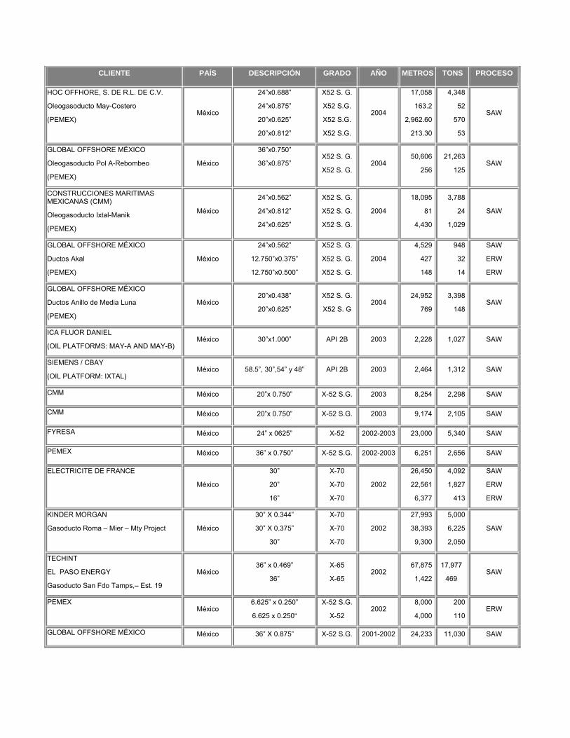
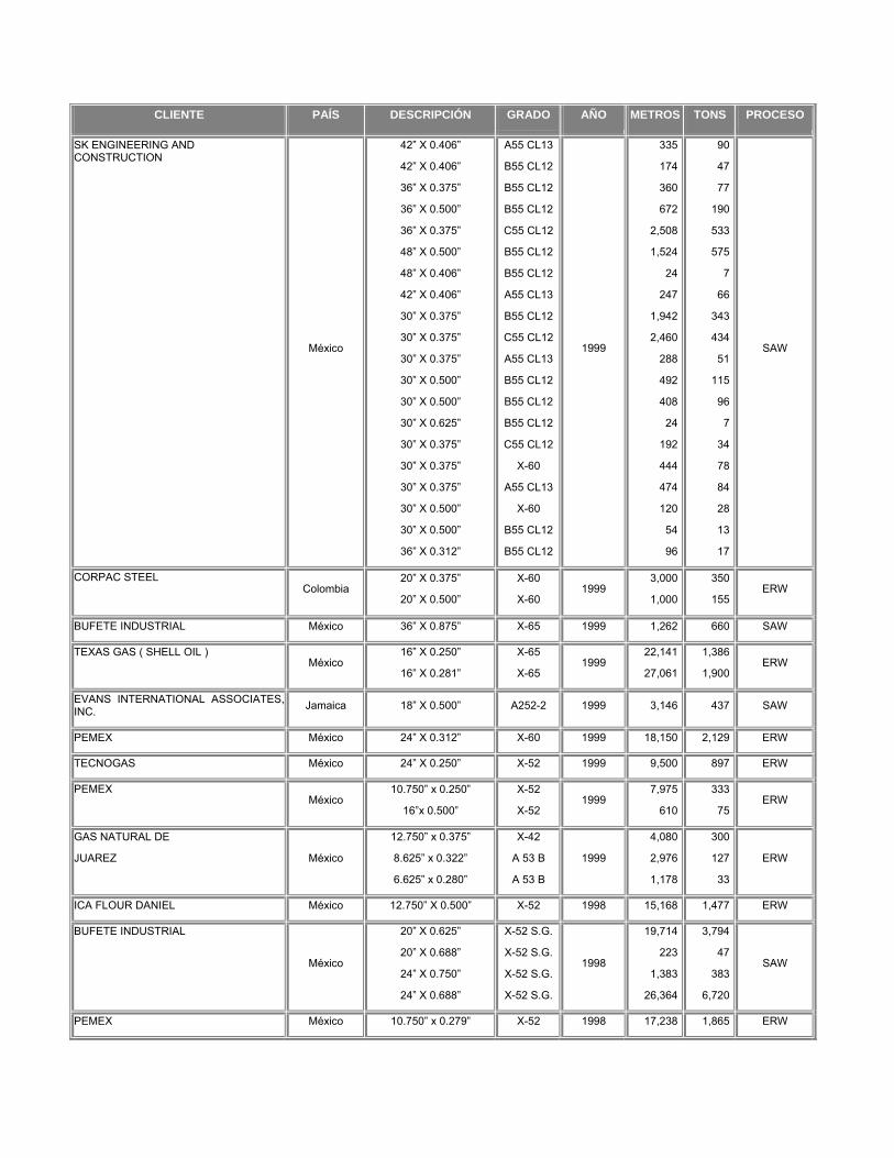
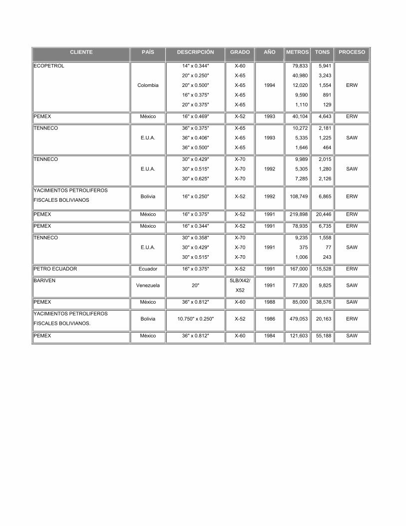
III. LIST OF MAIN PROJECT
CLIENTE PAÍS DESCRIPCIÓN GRADO AÑO METROS TONS PROCESO
Importadora Industrial Liang, S.A. de C.V.
Ductos 2009 FYRE Poza Rica (PEMEX) México 12”X0.375” X52 PSL1 2011 40,000 2,950 ERW
PEMEX EXPLORACIÓN Y PRODUCCION
Cont. 424011601 "Suministro de Tubería de Acero al carbono de diferentes diámetros, con o sin costura, para la construcción de Gasoductos y Lineas de descarga en el Activo Integral Burgos”
L360 MB (Equivalente a X52) ISO 3183-2, NRF-001-PEMEX-2007 HNA
México 6.625”x0.250”
8.625”x0.322”
L360 MB
L360 MB
2011-2012 Contrato Abierto
66,000
32,000
1,674
1,384
ERW
ERW
HOC OFFSHORE, S. DE R.L. DE C.V.
“Procura y construcción de un Oleogasoducto de 20"Ø x 3.05 KM de la Plataforma Kuil-A hacia la Plataforma Homol-A; a instalarse en el Golfo de México”. (PEMEX)
L450 MCS (Equivalente a X65 GA) ISO 3183-3, NRF-001-PEMEX-2007 HA
México 20”x0.688 L360 MCS 2011 3,329 703 SAW
PEMEX EXPLORACIÓN Y PRODUCCION
Cont. 425000651 “Adquisición de tuberías de diferentes diámetros para los Activos Integrales de la Región Sur, [Paquete RS-1]”
L360 MCS (Equivalente a X52 GA) ISO 3183-3, NRF-001-PEMEX-2007 HA
México 10.750”x0.365”
12.750”x0.375”
L360 MCS
L360 MCS
2011-2012 Contrato Abierto
24,440
13,688
1,472
1,010
ERW
ERW
Servicios y Construcciones Terrestres, S.A. de C.V.
“Construcción del Gasoducto de 36"Ø X 9.4 Batería Luna-Batería Pijije”. (PEMEX)
L360 MCS (Equivalente a X52 GA) ISO 3183-3, NRF-001-PEMEX-2007 HA
México 36”x0.938” L360 MCS 2010 9,871 5,160 SAW
COBRA INSTALACIONES MÉXICO, S.A. DE C.V.
"Ducto de 10" x 148 Km para Gasolinoducto del Bloque Nejo a CPG del Km-19"
Gasolinoducto de EDR Nejo 3 A EDR Nejo 1 y a EDR Nejo 2
Gasolinoducto de EDR Nejo 2 al CML
México
10.750”x0.250”
10.750”x0.250”
16”x0.250”
X52 M PSL2 2010
122,000
8,600
9,600
5,090
359
601
ERW
LM VAGA CONSTRUCCIONES S.A. DE C.V.
LPG DE 20" D.N. PAJARITOS – PALOMAS (PEMEX)
L360 MB ISO 3183-2, NRF-001-PEMEX-2007 HNA
México 20”x0.500”
20”x0312”
L360 MB
L360 MB 2010
1,520
1,643
236
163SAW

CLIENTE PAÍS DESCRIPCIÓN GRADO AÑO METROS TONS PROCESO
PERMADUCTO, S.A. DE C.V.
Gasoducto de 24"Ø x 16 km de la Plataforma Homol-A hacia la Plataforma Chuc-A. (PEMEX)
L360 MCS (Equivalente a X52 GA) ISO 3183-3, NRF-001-PEMEX-2007 HA
México 24”x0.688” L360 MCS 2010 17,447 4,448 SAW
GLOBAL OFFSHORE MÉXICO S. DE R.L. DE C.V.
Gasoducto de BN de 24” Ǿ X 8.4 Km , de la interconexión submarina de la línea L-156 (salida) hacia la plataforma E-KU-A2 (llegada) Campo Ku-Maloob-Zaap,. (PEMEX)
L360 MB ISO 3183-2, NRF-001-PEMEX-2007 HNA
México 24”x0.688”
24”x0.812”
L360 MB
L360 MB 2010
8,274
378
2,130
113SAW
Corpac 11225 Colombia 12.750”x0.375 X65 PSL 2010 45,000 3,319 ERW
GLOBAL OFFSHORE MÉXICO
Gasoducto de 36" Ø X 23.5 KM aprox., de la plataforma E-KU-A2 hacia AKAL-C6 en el campo Ku-Maloob-Zaap. (PEMEX)
L360 MCS (Equivalente a X52 GA) ISO 3183-3, NRF-001-PEMEX-2007 HA
México 36”x0.875”
36”x1”
L360 MCS
L360 MCS2010
27,014
524
13,189
292SAW
Corpac 11218 Colombia 12.750”x0.375” X42 2010 10,000 737 ERW
JD Fields 50117 USA 16”x0.500” X52 PSL2 GA 2010 4,465 550 ERW
Corpac 11106 Colombia 16x0.375 X42 2010 6,932 645 ERW
ICACSA Construcciones, S. de R.L. de C.V.
"LINEA DE 8” Ø x 14.765 km. JUJO-PAREDÓN"
L360 MB (Equivalente a X52) ISO 3183-2, NRF-001-PEMEX-2007 HNA
México 8.625”x0.344” L360 MB 2010 14,720 667 ERW
Corpac 10568 Colombia 16x0.375 X42 2010 17,513 1,631 ERW
Energia Occidente de México, de R.L. de C.V.
“Gasoducto a Guadalajara, Jalisco” (CFE) México
30”x0.335”
24”x0.322”
24”x0.386”
X70 PSL2
X70 PSL2
X70 PSL2
2009-2010
102,480
2,884
3,386
16,194
351
491
SAW
Gandy Technologies 9020 Canada 24”x0.410” A1053 2009 3,353 515 ERW/SAW
Corpac 10315 México 16x0.375 L360 MCS 2009 16,752 1,560 ERW
Corpac 10452 Colombia 16x0.375 5LB/X42 2009 6,000 522 ERW
CONDUX S.A. DE C.V.
"Gasoducto de 20” Ø x 3.4 km. aprox. de laPlataforma PP-KU-I hacia la Plataforma PP-KU-S (KMZ-55), en el campo Ku-Maloob-Zaap" (PEMEX)
L360 HA (Equivalente a X52) ISO 3183-3, NRF-001-PEMEX-2007
México 20”x0. 500” L360 HA 2009 2,954 458 SAW

CLIENTE PAÍS DESCRIPCIÓN GRADO AÑO METROS TONS PROCESO
CONAMSA Urbanizadora, S.A. de C.V., Construcciones GV de Monterrey, S.A. de C.V., Pavimentaciones y Excavaciones, S.A. de C.V.
Proy. Integral de Infraestructura de Agua Potable y Saneamiento Monterrey V Tanque Alianza Real al Tanque Fraile I Tramo I y II en García, N.L. y Tanque Fraile II al Tanque García en García, N.L.
México 24”x0.375” 5L B 2009 9,966 1,403 SAW
Cobra Instalaciones México, S.A. de C.V.
“Tubería de 8" de diámetro para Gas Crudo y Gas Procesado”
L360 HNA (Equivalente a X52) ISO 3183-2, NRF-001-PEMEX-2007
México 8.625”x0.344” L360 HNA 2009 14,600 661 ERW
GPA Energy S.A. de C.V.
“Gasoducto 30” x 67 Kms. Granjeno-Sta. Elena”
L485 MB (Equivalente a X70) ISO 3183-2, NRF-001-PEMEX-2007 HNA
México 30”x0.469” L485 MB 2009 67,400 14,836 SAW
Hoc Offshore S.A. de C.V.
“Ducto de 20" diam x 15 kms de la plataforma Xanab-1 a la plataforma Yaxche-B” (PEMEX)
L450 MCS (Equivalente a X65) ISO 3183-3, NRF-001-PEMEX-2007 HNA
México 20”x0.750” L450 MCS 2009 15,211 3,490 SAW
PEMEX EXPLORACIÓN Y PRODUCCION
“Suministro de tubería de acero al carbono de diferentes diámetros para líneas de conducción del Activo Integral Veracruz”
L360 MB (Equivalente a X52) ISO 3183-2, NRF-001-PEMEX-2007 HNA
México 10.750”x0.365” L360 MB 2009
Contrato abierto
18,700 1,126 ERW
PEMEX EXPLORACIÓN Y PRODUCCION
“Adq. de Tubería Servicio no Amargo de 6” Ø x 0.250, 8” Ø x .250, 10” Ø x 0.250, y 12” Ø x 0.280” de espesor de pared para el Proyecto Aceite Terciario del Golfo, incluye protección mecánica y puesta en sitio”
L360 MB (Equivalente a X52) ISO 3183-2, NRF-001-PEMEX-2007 HNA
México
6.625”x0.250”
8.625”x0.250”
10.750”x0.250”
12.750”x0.281”
L360 MB
L360 MB
L360 MB
L360 MB
2009
72,000
168,000
4,000
4,000
1,824
5,590
167
222
ERW
ERW
ERW
ERW
PEMEX EXPLORACIÓN Y PRODUCCION
“Suministro de tuberías conductoras de 20” incluyendo la asistencia técnica en la instalación”
México
20”x0.625”
Servicios
20”x0.625” +Zapata Flot.
X52
189 Piezas
2009-2012
Contrato abierto
150,847
12,633
29,031
454
SAW
SAW
PEMEX EXPLORACIÓN Y PRODUCCION
"Adquisición de tubería de línea, diferentes diámetros para los Activos de la Región Sur"
L360 MB (Equivalente a X52) ISO 3183-2, NRF-001-PEMEX-2007 HNA
México 16”x0.500” L360 MB 2008-2009
Contrato abierto
28,544 3,515 ERW

CLIENTE PAÍS DESCRIPCIÓN GRADO AÑO METROS TONS PROCESO
GLOBAL OFFSHORE MÉXICO
Oleogasoducto de 24" x 2.1 km aprox. de longitud de PP-Maloob-C hacia PP-Ku-H. (PEMEX)
L360 MCS (Equivalente a X52 GA) ISO 3183-3, NRF-001-PEMEX-2007 HA
México 24”x0.688”
24”x0.750”
L360 MCS
L360 MCS2008-2009
1,878
537
478
149SAW
Corpac 8493 Colombia
18”x0.344”
14”x0.375”
X65 PSL2
X65 PSL22008
18,000
37,000
1,738
3,005
ERW
ERW
Corpac 8499
USA
16”x0.375”
16”x0.250”
16”x0.219”
X56 PSL2
X56 PSL2
X56 PSL2
2008-2009
3,048
4,828
75,810
284
302
4,164
ERW
Copac 8467 Colombia 16”x0.375” 5LB/X42 PSL1 2008 6,000 559 ERW
Corpac 8438 USA 16”x0.250” X60 PSL2 2008 45,720 2,861 ERW
National Gas Company of Trinidad and Tobago (NGC)
Union Pipeline Project
Trinidad & Tobago
24”x0.562”
16”x0.375”
X70 PSL2
X65 PSL22008
8,703
1,964
1,822
183
SAW
ERW
PEMEX EXPLORACIÓN Y PRODUCCION
“Suministro de tuberías conductoras de 30” incluyendo la asistencia técnica en la instalación”
México
30”x1.000”
Servicios
30”x1.000” +Zapata Flot.
X52
30 Piezas
2008-2011
Contrato abierto
15,500
1,270
7,143
357
SAW
SAW
CONDUX, S.A. DE C.V.
Ayin A (PEMEX)
L450 MCS (Equivalente a 65 GA) ISO 3183-3, NRF-001-PEMEX-2007 HA
México 20”x0.750” L450 MCS 2008-2009 22,385 5,136 SAW
CONDUX, S.A. DE C.V.
Tumut-Chuc-A (PEMEX)
L360MCS (Equivalente a 52 GA) ISO 3183-3, NRF-001-PEMEX-2007 HA
México 20”x0.438”
20”x0.625” L360 MCS 2008-2009
9,628
213
1,311
41SAW
OCEANOGRAFIA, S.A DE C.V.
Gasoducto Plataforma Ixtal-A a la Plataforma Abkatun-A (PEMEX)
L415 MCS (Equivalente a 60 GA) ISO 3183-3, NRF-001-PEMEX-2007 HA
México 30”x0.750” L415 MCS 2008 21,775 7,592 SAW
Tractebel Digaqro S.A. de C.V.
Gasoducto Querétaro. México 10.750”x0.312” X52 2008 19,500 1,009 ERW
GLOBAL OFFSHORE MÉXICO
Oleogasoducto de 24” Ø X 12 Km de Longitud para el Oleogasoducto clave 252 del km. 6+100 a la plataforma Abkatun D (PEMEX)
L360 MCS (Equivalente a X52 GA) ISO 3183-3, NRF-001-PEMEX-2007 HA
México 24”x0.688”
24”x0.750”
L360 MCS
L360 MCS2008
12,383
275
3,157
76SAW
CORPAC 8311 ESTADOS UNIDOS
16”x0.250”
16”x0.375”
16”x0.250”
X52 PSL2
X65 PSL2
X60 PSL2
2008
42,672
48,768
15,240
2,671
4,542
954
ERW

CLIENTE PAÍS DESCRIPCIÓN GRADO AÑO METROS TONS PROCESO
Dowell Schlumberger de México, S.A. De C.V.
Ejecución de obras de perforación e infraestructura en la Cuenca de Burgos (PEMEX)
L360 MB (Equivalente a X52) ISO 3183-2, NRF-001-PEMEX-2007
México 24”x0.750”
24”x0.875”
L360 MB
L360 MB 2008
40,400
1,000
11,197
322SAW
OCEANOGRAFIA, S.A DE C.V.
Oleogasoducto Plataforma Sea Pony Che-1 a la Plataforma Homol-A (PEMEX)
L415 MCS (Equivalente a 60 GA) ISO 3183-3, NRF-001-PEMEX-2007 HA
México 16”x0.500”
L415 MCS 2008 2,659 328 ERW
PEMEX EXPLORACIÓN Y PRODUCCION
“Suministro de tuberías conductoras de 20” incluyendo la asistencia técnica en la instalación”
México
20”x0.625”
Servicios
20”x0.625” +Zapata Flot.
X52
34 Piezas
2006-2008
69,140
3,113
13,341
82
SAW
SAW
Heisco
(KOC-Kuwait Oil Company) Kuwait 20”x0.625” X52 psl 2 2008 4,284 825 SAW
Corpac 8213 Estados Unidos 12.750”x0.375” X52 psl2 2008 22,464 1,557 ERW
Corpac 7866 Colombia 14”x0.375” X42 2008 2,570 209 ERW
Kentech ME & I / Corpac México 48”x0.562” ASTM A134 2008 1,967 834 SAW
CONSTRUCTORA MONROG, S.A. DE C.V.
“Gasoducto de 36” del área de trampas separación Oxiacaque a trampas compresoras Cunducan."
(PEMEX)
L360 MCS (Equivalente a X52 GA) ISO 3183-3, NRF-001-PEMEX-2007 HA
México
36”x0.500”
24”x0.500”
20”x0.500”
42”x0.500”
L360 MCS
L360 MCS
L360 MCS
5L B
2008
6,417
268
12
27
1,815
50
2
58
SAW
OCEANOGRAFÍA, S.A. DE C.V.
Oleogasoducto Atun-D – Bagre-A 12”
(PEMEX)
L360 MCS (Equivalente a X52 GA) ISO 3183-3, NRF-001-PEMEX-2007 HA
México
12.750”x0.375”
12.750”x0.406”
6.625”x0.250”
6.625”x0.312”
8.625”x0.344”
L360 MCS
L360 MCS
L360 MCS
L360 MCS
L360 MCS
2007-2008
12,577
278
435
172
25
928
22
11
6
1
ERW
SOCIEDAD IND. DE CONSTRUCC. ELECTRICAS, S.A. DE C.V. / MARUSA, S.A. DE C.V.
Oleogasoducto Tizón a Batería Luna (PEMEX)
L360 MCS (Equivalente a X52 GA) ISO 3183-3, NRF-001-PEMEX-2007 HA
México 20”x0.625” L360 MCS 2007 10,552 2,031 SAW
CLIENTE PAÍS DESCRIPCIÓN GRADO AÑO METROS TONS PROCESO
PROVEEDORES Y ASESORES DE COMERCIO EXTERIOR, S. A. DE C.V.
Rehabilitación y Construcción de Ductos en el área de San Andrés Activo Integral Poza Rica – Altamira.
(PEMEX)
L360 MCS (Equivalente a X52 GA) ISO 3183-3, NRF-001-PEMEX-2007 HA
México 12.750”x0.375” L360 MCS 2007 20,000 1,475 ERW
GLOBAL OFFSHORE MÉXICO
Linea 252 de 24” IxtalA/Abkatun D Perforación.
(PEMEX)
México 24”x0.750”
24”x0.625”
X52 G.A.
X52 G.A. 2007
3,276
3,049
907
708SAW
PEMEX PLORACIÓN Y PRODUCCION
Ducto Entronque Arcabuz 5 a Planta Culebra Norte
México 24”x0.625”
24”x0.750”
X52
X52 2007
30,456
1,744
7,071
484
SAW
SAW
DEMAR INSTALADORA Y CONSTRUCTORA, S.A. DE C.V.
Gasoducto Marsopa a Punta de Piedra México
20”x0.438”
20”x0.625”
X52 G.A.
X52 G.A. 2007
36,745
1,300
5,004
250
SAW
SAW
PEMEX GAS Y PETROQUIMICA BASICA
Gasoducto Jalapa México 48”x0.875” X65 2007 22,476 14,730 SAW
PEMEX PLORACIÓN Y PRODUCCION
Gasoducto Cuervito-Sierrita México 24”x0.875” X52 2006 34,349 11,046 SAW
OCEANOGRAFÍA, S.A. DE C.V.
Líneas 48, 50 y Takin
(PEMEX)
México
24”x0.750”
24”x0.812”
16”x0.375”
X52 G.A.
X60
X52 G.A.
2006
7,602
5,559
9,389
2,107
1,664
874
SAW
SAW
ERW
OCEANOGRAFÍA, S.A. DE C.V.
Líneas Marinas Sihil 3, 4, , TQ1 y TQ3
(PEMEX) México
20”x0.438”
24”x0.562”
12.750”x0.344”
12.750”x0.500”
16”x0.375”
8.625”x0.344”
X52 G.A.
X52 G.A.
X52 G.A.
X52 G.A.
X52 G.A.
X52 G.A
2006
622
586
1,756
109
3,440
427
85
123
119
11
320
19
SAW
SAW
ERW
ERW
ERW
ERW
OCEANOGRAFÍA, S.A. DE C.V.
Líneas Marinas Paquete Bolontiku
(PEMEX)
México
16”x0.469”
16”x0.500”
10.750”x0.365”
X60 G.A.
X60 G.A.
X52 G.A.
2006
2,090
900
6,300
241
111
379
ERW
CONDUX, S.A. DE C.V.
Líneas Marinas Paquete H
(PEMEX)
México
20”x0.625”
20”x0.562”
30”x0.812”
X52
X52
X52 G.A.
2006
145
4,788
6,100
28
831
2,298
SAW
PEMEX PLORACIÓN Y PRODUCCION
Tubería para Dos Bocas, Tbs. México 30”x1.000” API 2B 2006 2,004 924 SAW
GLOBAL OFFSHORE MÉXICO
Linea 47
(PEMEX)
México 24”x0.750” X52 G.A. 2006 8,528 2,363 SAW

CLIENTE PAÍS DESCRIPCIÓN GRADO AÑO METROS TONS PROCESO
GLOBAL OFFSHORE MÉXICO
Gasoducto Akal Gr a Akal-C/6 y Nitrogenoducto 36"
(PEMEX)
México
36”x0.812”
36”x0.875”
36”x0.688”
X60
X60
X52 G.A.
2006
17,458
305
2,537
7,928
149
980
SAW
GLOBAL OFFSHORE MÉXICO
Líneas Marinas 38, 39, 40 y 41
(PEMEX)
México
30”x0.812”
30”x0.875”
24”x0.688”
X52 G.A.
X52 G.A.
X52 G.A.
2006
10,955
9,162
8,150
4,127
3,711
2,071
SAW
HOC OFFHORE, S. DE R.L. DE C.V.
Cinco ductos marinos y dos Nitrogenoductos de 24”
(PEMEX) México
24”x0.562”
24”x0.625”
20”x0.500”
24”x0.750”
24”x0.938”
20”x0.562”
20”x0.625”
X52 G.A.
X52 G.A.
X52 G.A.
X60
X60
X52
X52
2006
180
108
4,256
17,663
700
3,500
288
38
25
659
4,895
240
608
55
SAW
GREEN ENERGY LIBRAMIENTO, S. DE R.L.
Gasoducto Querétaro
(PEMEX)
México 24”x0.406” X65 2005-2006 65,935 10,038 SAW
GLOBAL OFFSHORE MÉXICO
Líneas Marinas 16
(PEMEX)
México 36”x0.875”
36”x0.938”
X52 G.A
X52 G.A. 2005-2006
24,161
268
11,802
140SAW
PEMEX PLORACIÓN Y PRODUCCION
Gasoducto Sierrita –Cuervitos México 24”x0.875 X52 2005-2006 13,050 4,197 SAW
GLOBAL OFFSHORE MÉXICO
Líneas Marinas 13 y 27
(PEMEX) México
12.750”x0.375”
12.750”x0.500”
24”x0.562”
24”x0.625”
X52
X52
X52 G.A
X52 G.A.
2005
1,411
73
2,256
110
104
7
466
25
ERW
ERW
SAW
SAW
TRANSPORTADORA DE GAS NATURAL DE LA HUASTECA / TRANSCANADA
Gasoducto Tamazunchale
(Comisión Federal de Electricidad)
México
36”x0.375”
36”X0.449”
36”X0.539”
X65 PSL2
X65 PSL2
X65 PSL2
2005
55,029
6,000
2,556
11,685
1,522
776
SAW
OCEANOGRAFÍA, S.A. DE C.V.
Gasoducto de Enlace a Pol A
(PEMEX)
México 36”x0.750”
36”x1.000”
X52 GA
X52 GA 2005
56,600
305
23,783
171SAW
CONDUX, S.A. DE C.V.
Oleogasoducto Líneas 3, 7, 8 y 30
(PEMEX) México
30”x0.812”
24”x0.688”
24”x0.625”
12.750”x0.375”
12.750”x0.500”
X52 G.A.
X52 G.A.
X52 G.A.
X52
X52
2005
7,560
4,119
2,476
677
64
2,847
1,050
575
50
6
SAW
SAW
SAW
ERW
ERW

CLIENTE PAÍS DESCRIPCIÓN GRADO AÑO METROS TONS PROCESO
HOC OFFHORE, S. DE R.L. DE C.V.
Oleogasoducto Líneas 4, 6, 31 y 32
(PEMEX) México
24”x0.688”
24”x0.625”
12.750”x0.375”
12.750”x0.500”
X52 G.A.
X52 G.A.
X52
X52.
2005
1,905
2,025
6,724
134
486
470
496
13
SAW
SAW
ERW
ERW
CONDUX, S.A. DE C.V.
Oleogasoductos SINAN de 16” y 20”
(PEMEX)
México
20”x0.812”
16”x0.500”
16”x0.500”
X60 G.A.
X60 G.A.
X52 G.A.
2005
506
3,453.6
1,502
126
425
185
SAW
ERW
ERW
PEMEX EXPLORACIÓN Y PRODUCCION
Gasoducto Planta Cuervitos a Planta Culebra Sur.
México 24”x0.875” X52 2005 20,157 6,482 SAW
PEMEX EXPLORACIÓN Y PRODUCCION
Oleogasoducto Arroyo Prieto 17-Bateria Ogarrio 5
México 8.625” x 0.312“
8.625” x 0.375“ X-52 2005
19,550
2,050
805
100ERW
GLOBAL OFFSHORE MÉXICO
Oleoducto PP-MALOB-B
(PEMEX) México
24”x0.688”
12.750”x0.375”
20”x0.562”
12.75”x0.500”
20”x0.625”
X52 S.G
X52
X52
X52
X52.
2005
2,512
3,445
3,865
153
247
640
254
671
15
48
SAW
ERW
SAW
ERW
SAW
GLOBAL OFFSHORE MÉXICO
Oleoducto Lobina-Carpa
(PEMEX)
México 16”x0.500”
12.750”x0.500”
X52 S.G.
X52 S.G. 2005
36,126
15,094
4,450
1,470ERW
CONDUX, S. A. DE C.V.
Oleogasoducto Yaxche-A-Bateria
(PEMEX)
México
24”x0.750”
24”x1.000”
16”x0.500”
X52 S.G.
X52 S.G.
X52 S.G.
2004-2005
45,284
1,651
10,321
12,550
603
1,270
SAW
SAW
ERW
Oceanografía
Líneas 19, 20 y 24
(PEMEX)
México
20”x0.500”
20”x0.562”
20”x0.625”
X52
X52
X52
2004
20,899
7,188
597
3,238
1,248
115
SAW
LIPSA
Gasoducto 36 », Dos Bocas la Trinidad
(PEMEX)
México 36”x0.812” X60 S.G. 2004 14,688 6,670 SAW
CONDUX
Dos Líneas KU
(PEMEX)
México 30”x0.688”
30”x0.750”
X52 S.G.
X52 S.G. 2004
2,579
4,190
827
1,461SAW
CORPAC
(ECOPETROL) Colombia 16”x0.344” X60 2004 10,000 856 ERW
SIGMA
Rehabilitación Oleoducto de 24 » Madero-Caderyta
(PEMEX)
México 24”x0.375” X52 2004 10,000 1,408 SAW
CLIENTE PAÍS DESCRIPCIÓN GRADO AÑO METROS TONS PROCESO
HOC OFFHORE, S. DE R.L. DE C.V.
Oleogasoducto May-Costero
(PEMEX) México
24”x0.688”
24”x0.875”
20”x0.625”
20”x0.812”
X52 S. G.
X52 S.G.
X52 S.G.
X52 S.G.
2004
17,058
163.2
2,962.60
213.30
4,348
52
570
53
SAW
GLOBAL OFFSHORE MÉXICO
Oleogasoducto Pol A-Rebombeo
(PEMEX)
México
36”x0.750”
36”x0.875”
X52 S. G.
X52 S. G. 2004
50,606
256
21,263
125SAW
CONSTRUCCIONES MARITIMAS MEXICANAS (CMM)
Oleogasoducto Ixtal-Manik
(PEMEX)
México
24”x0.562”
24”x0.812”
24”x0.625”
X52 S. G.
X52 S. G.
X52 S. G.
2004
18,095
81
4,430
3,788
24
1,029
SAW
GLOBAL OFFSHORE MÉXICO
Ductos Akal
(PEMEX)
México
24”x0.562”
12.750”x0.375”
12.750”x0.500”
X52 S. G.
X52 S. G.
X52 S. G.
2004
4,529
427
148
948
32
14
SAW
ERW
ERW
GLOBAL OFFSHORE MÉXICO
Ductos Anillo de Media Luna
(PEMEX)
México 20”x0.438”
20”x0.625”
X52 S. G.
X52 S. G 2004
24,952
769
3,398
148SAW
ICA FLUOR DANIEL
(OIL PLATFORMS: MAY-A AND MAY-B) México 30”x1.000” API 2B 2003 2,228 1,027 SAW
SIEMENS / CBAY
(OIL PLATFORM: IXTAL) México 58.5”, 30”,54” y 48” API 2B 2003 2,464 1,312 SAW
CMM México 20”x 0.750” X-52 S.G. 2003 8,254 2,298 SAW
CMM México 20”x 0.750” X-52 S.G. 2003 9,174 2,105 SAW
FYRESA México 24” x 0625” X-52 2002-2003 23,000 5,340 SAW
PEMEX México 36” x 0.750” X-52 S.G. 2002-2003 6,251 2,656 SAW
ELECTRICITE DE FRANCE
México
30”
20”
16”
X-70
X-70
X-70
2002
26,450
22,561
6,377
4,092
1,827
413
SAW
ERW
ERW
KINDER MORGAN
Gasoducto Roma – Mier – Mty Project México
30” X 0.344”
30” X 0.375”
30”
X-70
X-70
X-70
2002
27,993
38,393
9,300
5,000
6,225
2,050
SAW
TECHINT
EL PASO ENERGY
Gasoducto San Fdo Tamps,– Est. 19
México 36” x 0.469”
36”
X-65
X-65 2002
67,875
1,422
17,977
469 SAW
PEMEX México
6.625” x 0.250”
6.625 x 0.250“
X-52 S.G.
X-52 2002
8,000
4,000
200
110ERW
GLOBAL OFFSHORE MÉXICO México 36” X 0.875” X-52 S.G. 2001-2002 24,233 11,030 SAW

CLIENTE PAÍS DESCRIPCIÓN GRADO AÑO METROS TONS PROCESO
FABRIGAS
Guatemala
120” X 0.562” 108” X 0.688” 100” X 0.818” 100” X 1.250” 60” X 0.812”
A-139-E A-139-E A-139-E A-139-E A-139-E
2001
210 160 100 240 75
227
191
131
483
59
SAW
CONSTRUCTORA LIMPEZ México 16” X 0.438” X-52 S.G. 2001 10,650 1,154 ERW FYRESA México 30” X 0.344” X-52 2001 7,000 1,134 SAW COBSA México 20” X 0.312” X-52 2001 7,658 748 ERW CONSTRUCCIONES Y DISEÑOS ROHER México
6.625” X 0.280” 8.625” X 0.344” 10.750” X 0.344”
X-42 X-42 X-52
2001 28,940 20,580 6,800
817
874
387
ERW
TRACOTAMSA México 10.750” X 0.344” X-52 2001 26,000 1,566 ERW GLOBAL OFFSHORE MÉXICO México 24” X 0.625”
24” X 0.562” X-52 S.G.
X-52 S.G.2001 3,416
6,246 793
1,308SAW
CONSTRUCTORA AGUILAR SILVA México 10.750” X 0.365” X-52 2001 10,000 602 ERW GAS NATURAL MÉXICO México 24” X 0.500” X-65 2001 6,500 1,214 SAW CMM
México 24” X 0.625” 24” X 0.688”
X-52 S.G.
X-52 S.G.2001 7,248
3,600 1,683
836SAW
PEMEX México 6.625” X 0.280” X-52 2001 14,000 395 ERW PEMEX México 12.750” X 0.330” X-52 2001 15,150 987 ERW OPC-BN MÉXICO México 138” X 1.125” A-134 2000 304 756 SAW PEMEX México 24” X 0.688” X-60 2000 4,920 1,255 SAW PEMEX México 30” X 0.500” X-65 2000 4,550 1,068 SAW SERVICIOS DE AGUA Y DRENAJE DEMONTERREY
Tramo comprendido en Santiago, N. L. México 60”x0500” 5LB 2000 1,600 757 SAW
GAS NATURAL México 6.625” X 0.322” 5LB 2000 10,000 323 ERW PEMEX México 8.625” X 0.312” X-52 2000 22,800 940 ERW PEMEX
México 8.625” X 0.322” 48” X 0.625”
5LB X-65 2000 5,000
962 212
436
ERW SAW
MEXIGAS México
14” X 0.210” 12.750” X 0.203” 10.750” X 0.203”
X-65 X-65 X-65
2000 5,000 7,632 3,200
230
309
109
ERW ERW ERW
CLIENTE PAÍS DESCRIPCIÓN GRADO AÑO METROS TONS PROCESO
SK ENGINEERING AND CONSTRUCTION
México
42” X 0.406” 42” X 0.406” 36” X 0.375” 36” X 0.500” 36” X 0.375” 48” X 0.500” 48” X 0.406” 42” X 0.406” 30” X 0.375” 30” X 0.375” 30” X 0.375” 30” X 0.500” 30” X 0.500” 30” X 0.625” 30” X 0.375” 30” X 0.375” 30” X 0.375” 30” X 0.500” 30” X 0.500” 36” X 0.312”
A55 CL13
B55 CL12
B55 CL12
B55 CL12
C55 CL12
B55 CL12
B55 CL12
A55 CL13
B55 CL12
C55 CL12
A55 CL13
B55 CL12
B55 CL12
B55 CL12
C55 CL12
X-60 A55 CL13
X-60 B55 CL12
B55 CL12
1999
335 174 360 672
2,508 1,524
24 247
1,942 2,460
288 492 408 24
192 444 474 120 54 96
90
47
77
190
533
575
7
66
343
434
51
115
96
7
34
78
84
28
13
17
SAW
CORPAC STEEL Colombia 20” X 0.375”
20” X 0.500” X-60 X-60 1999 3,000
1,000 350
155ERW
BUFETE INDUSTRIAL México 36” X 0.875” X-65 1999 1,262 660 SAW TEXAS GAS ( SHELL OIL )
México 16” X 0.250” 16” X 0.281”
X-65 X-65 1999 22,141
27,061 1,386
1,900ERW
EVANS INTERNATIONAL ASSOCIATES,INC. Jamaica 18” X 0.500” A252-2 1999 3,146 437 SAW
PEMEX México 24” X 0.312” X-60 1999 18,150 2,129 ERW TECNOGAS México 24” X 0.250” X-52 1999 9,500 897 ERW PEMEX
México 10.750” x 0.250” 16”x 0.500”
X-52 X-52 1999 7,975
610 333
75ERW
GAS NATURAL DE JUAREZ México
12.750” x 0.375” 8.625” x 0.322” 6.625” x 0.280”
X-42 A 53 B A 53 B
1999 4,080 2,976 1,178
300
127
33
ERW
ICA FLOUR DANIEL México 12.750” X 0.500” X-52 1998 15,168 1,477 ERW BUFETE INDUSTRIAL
México
20” X 0.625” 20” X 0.688” 24” X 0.750” 24” X 0.688”
X-52 S.G.
X-52 S.G.
X-52 S.G.
X-52 S.G.
1998
19,714 223
1,383 26,364
3,794
47
383
6,720
SAW
PEMEX México 10.750” x 0.279” X-52 1998 17,238 1,865 ERW

CLIENTE PAÍS DESCRIPCIÓN GRADO AÑO METROS TONS PROCESO
CCC PEMEX
México
24” x 0.625” 36” x 0.875” 36” x 0.900” 36” x 0.875” 36” X 1.125” 16” X 0.475” 20” x 0.562”
X-65 S.G.
X-65 S.G.
X-65 S.G.
X-65 S.G.
X-65 S.G.
X-65 S.G.
X-65 S.G.
1998
7,826 5,205
17,238 15,738
126 2,123
256
1,804
2,541
8,944
7,691
79
249
45
SAW SAW SAW SAW SAW ERW SAW
SK ENGINEERING
México
24” x 0.312” 24” x 0.375” 24” x 0.500”
12.750” X 0.250” 12.750” X 0.281” 12.750” X 0.406”
X-60 X-60 X-60 X-60 X-60 X-60
1998
224,952 36,468 2,184
246,490 25,596 1,500
26,425
5,135
407
12,242
1,425
120
SAW SAW SAW ERW ERW ERW
PEMEX
México
30” x 0.500” 30” x 0.625” 30” x 0.750” 30” x 0.875” 30” x 1.000”
A 36 A 36 A 36 A 36 A 36
1998
17,238 398
38
27
15,738
4,045
116
13
10
6,818
SAW
PETROZUATA Venezuela 36” x 0.438”
36” x 0.500” X-52 X-52 1998 20,000
1,153 4,943
325SAW
PROMIGAS Colombia 24” x 0.375”
24” x 0.500” X-60 X-60 1997 23,500
2,850 3,323
534SAW
PEMEX México 36” x 0.875” X-52 S.G. 1997 7,417 3,893 SAW PEMEX México 24” x 0.406” X-52 S.G. 1997 14,700 1,880 SAW BECHTEL
India 24” x 0.688” 20” x 0.594” 18” x 0.500”
A 671 A 671 A 671
1997 25,300 3,920
28,950
7,685
895
4,091
SAW
VAN LEEUWEN PIPE & TUBE Venezuela 24” X 0.375”
30” X 0.375” X-52 X-52 1997 10,099
2,406 1,847
441ERW
NOVA GAS E.U.A. 48” X 0.500” X-60 1997 4,800 1,800 SAW PROTEXA PEMEX México 36” x 0.875” X-52 S.G. 1997 45,100 22,027 SAW ARCOS-ARCABUS PEMEX México 24” x 0.625” X-52 1997 46,000 10,686 SAW TITAS GAS
Bangladesh 20” x 0.469” 28” x 0.438”
X-52 X-52 1997 41,000
298 5,968
57SAW
CEGSA PEMEX México 24” x 0.469”
24” x 0.562” X-52 S.G.
X-52 S.G.1997 48,300
5,410 8,936
1,521SAW
CMM PEMEX México 24” x 0.750” X-52 S.G. 1997 48,300 681 SAW PEMEX
México Pipe with WT up to 1.5” 1997 48,300 5,410 3,945 SAW
PEMEX México 20" x 0.312" X-52 1997 12,330 1,201 ERW

CLIENTE PAÍS DESCRIPCIÓN GRADO AÑO METROS TONS PROCESO
EMPRESAS PÚBLICAS DE MEDELLIN
Colombia
20" x 0.250" 16" x 0.250"
8.625" x 0.188" 66.625" x 0.188"
4" x 0.188" 3" x 0.188"
X-42 X-42 X-42 X-42 X-42 X-42
1997
49,400 12,520
9,950
579
20,031
19,615
3,910
790
252
115
258
194
ERW
TENNECO GAS & TRANSMISSION Australia
30" X 0.281" 30" X 0.375" 30" X 0.500"
X-70 X-70 X-70
1997 4,572 1,097
427
660
210
110
SAW
INDUSTRIAS DEL HIERRO México 30" X 1.000" A36 2B 1997 4,902 2,259 SAW CCC PEMEX México 30" x 0.750" X-52 S.G. 1996 16,483 5,986 SAW DICA PEMEX México 24" x 0.625" X-52 1996 16,483 2,492 SAW AGUILAR SILVA PEMEX México 36" x 0.812" X-60 1996 16,483 4,793 SAW ICA PEMEX México 24" x 0.562" X-52 S.G. 1996 16,483 7,282 SAW COMMISA PEMEX México 36" x 0.750" X-52 S.G. 1996 16,483 17,707 SAW JOSE CARTELLONE CONSTRUCC. CIVILES Costa Rica 47" x 0.750" X-52 1996 16,483 1,214 SAW
PEMEX GAS Y PETROQUIMICA BASICA México 20" X 0.312" X-52 1996 12,300 1,200 ERW CONST. ESPECIALIZADAS DEL GOLFOPEMEX México 24" X 0.469" X-52 S.G. 1996 23,000 4,000 SAW
ENTUBAMIENTO Y CONST. S.A. México 30" X 0.312" X-65 1996 6,200 1,000 SAW PETROECUADOR Ecuador 20" X 0.500" X-42 1996 5,000 775 SAW McCONNELL DOWELL
Bangladesh 30" x 0.562" 30" x 0.688" 24" x 0.562"
X-52 X-52 X-52
1995 54,900 3,620
100
14,476
1,163
21
SAW
TENNECO GAS & TRANSMISSION Australia 16" x 0.375" X-65 1995 125,000 29,518 ERW SOC. CONTRACTUAL EL ALBA Chile 22" x 0.250" 5LB 1995 125,000 804 ERW CONSTRUCTORA BELFI Chile 30" x 0.469" A 252 3 1995 125,000 2,244 SAW PEMEX México 24" x 0.562" X-52 1995 53,328 2,220 SAW PEMEX México 24" x 0.688" X-52 1995 53,328 3,432 SAW PEMEX México 16" x 0.312" X-52 1995 53,328 4,140 ERW DICA PEMEX México 12.750" X 0.750" X-52 1995 30,500 1,799 ERW INDIAN OIL CORPORATION LTD.
India 22" x 0.250" 22" x 0.469"
X-65 X-65 1994 686,000
350 60,000
59SAW
PEMEX México 36" x 0.812" X-52 1994 40,104 18,499 SAW SERVICIOS CARRETEROS MEXICANOS México 48" x 0.500" A 36 1994 11,500 4,276 SAW
CLIENTE PAÍS DESCRIPCIÓN GRADO AÑO METROS TONS PROCESO
ECOPETROL
Colombia
14" x 0.344" 20" x 0.250" 20" x 0.500" 16" x 0.375" 20" x 0.375"
X-60 X-65 X-65 X-65 X-65
1994
79,833
40,980
12,020
9,590
1,110
5,941
3,243
1,554
891
129
ERW
PEMEX México 16" x 0.469" X-52 1993 40,104 4,643 ERW TENNECO
E.U.A. 36" x 0.375" 36" x 0.406" 36" x 0.500"
X-65 X-65 X-65
1993 10,272 5,335 1,646
2,181
1,225
464
SAW
TENNECO E.U.A.
30" x 0.429" 30" x 0.515" 30" x 0.625"
X-70 X-70 X-70
1992 9,989 5,305 7,285
2,015
1,280
2,126
SAW
YACIMIENTOS PETROLIFEROS FISCALES BOLIVIANOS Bolivia 16" x 0.250" X-52 1992 108,749 6,865 ERW
PEMEX México 16" x 0.375" X-52 1991 219,898 20,446 ERW PEMEX México 16" x 0.344" X-52 1991 78,935 6,735 ERW TENNECO
E.U.A. 30" x 0.358" 30" x 0.429" 30" x 0.515"
X-70 X-70 X-70
1991 9,235
375 1,006
1,558
77
243
SAW
PETRO ECUADOR Ecuador 16" x 0.375" X-52 1991 167,000 15,528 ERW BARIVEN
Venezuela 20" 5LB/X42/
X52 1991 77,820 9,825 SAW
PEMEX México 36" x 0.812" X-60 1988 85,000 38,576 SAW YACIMIENTOS PETROLIFEROS FISCALES BOLIVIANOS. Bolivia 10.750" x 0.250" X-52 1986 479,053 20,163 ERW
PEMEX México 36" x 0.812" X-60 1984 121,603 55,188 SAW

IV. PRODUCTION CAPACITY
MILL DIAMETER LENGTH THICKNESS STEELIn. Ft. In. GRADE PROCESS M. TONS. METERS M. TONS. METERS
# 1 36" 40 - 51 0.500" UP TO X-80 SAW 13,333 47,500 160,000 570,000
# 2 24" 40 - 51 0.375" UP TO X-80 ERW/SAW 11,667 82,500 140,000 990,000
# 3 12 3/4" 30 - 60 0.312" UP TO X-80 ERW 4,167 83,333 50,000 1,000,000
29,167 213,333 350,000 2,560,000
NOTES:1.- 3 shifts per day2.- 6 days per week3.- 25 days per month4.- 12 months per year 5.- The production capacity calculation was done considering a representative
product and the result is an approximated value of the nominal capacity.
CAPACITY/MONTH CAPACITY/YEARDIMENTIONS
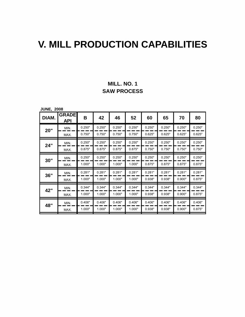
V. MILL PRODUCTION CAPABILITIES
MILL. NO. 1 SAW PROCESS
DIAM. GRADE API B 42 46 52 60 65 70 80
MIN. 0.250" 0.250" 0.250" 0.250" 0.250" 0.250" 0.250" 0.250"
MAX. 0.750" 0.750" 0.750" 0.750" 0.625" 0.625" 0.625" 0.625"
MIN. 0.250" 0.250" 0.250" 0.250" 0.250" 0.250" 0.250" 0.250"
MAX. 0.875" 0.875" 0.875" 0.875" 0.750" 0.750" 0.750" 0.750"
MIN. 0.250" 0.250" 0.250" 0.250" 0.250" 0.250" 0.250" 0.250"
MAX. 1.000" 1.000" 1.000" 1.000" 0.875" 0.875" 0.875" 0.875"
MIN. 0.281" 0.281" 0.281" 0.281" 0.281" 0.281" 0.281" 0.281"
MAX. 1.000" 1.000" 1.000" 1.000" 0.938" 0.938" 0.900" 0.875"
MIN. 0.344" 0.344" 0.344" 0.344" 0.344" 0.344" 0.344" 0.344"
MAX. 1.000" 1.000" 1.000" 1.000" 0.938" 0.938" 0.900" 0.875"
MIN. 0.406" 0.406" 0.406" 0.406" 0.406" 0.406" 0.406" 0.406"
MAX. 1.000" 1.000" 1.000" 1.000" 0.938" 0.938" 0.900" 0.875"
36"
42"
48"
JUNE, 2008
20"
24"
30"

MILL NO. 2 DSAW / ERW PROCESS
DIAM. GRADE API B 42 46 52 H-40 J-
55 60 65 70 80
MIN. 0.219" 0.219" 0.219" 0.219" 0.219" 0.219" 0.219" 0.219" 0.219"
MAX. 0.500" 0.500" 0.500" 0.500" 0.500" 0.500" 0.500" 0.438" 0.438"
MIN. 0.219" 0.219" 0.219" 0.219" 0.219" 0.219" 0.219" 0.219" 0.219"
MAX. 0.625" 0.625" 0.625" 0.625" 0.562" 0.500" 0.500" 0.500" 0.500"
MIN. 0.219" 0.219" 0.219" 0.219" 0.219" 0.219" 0.219" 0.219" 0.219"
MAX. 0.625" 0.625" 0.625" 0.625" 0.562" 0.500" 0.500" 0.500" 0.500"
MIN. 0.250" 0.250" 0.250" 0.250" 0.250" 0.250" 0.250" 0.250" 0.250"
MAX. 0.625" 0.625" 0.625" 0.625" 0.625" 0.562" 0.562" 0.562" 0.562"
MIN. 0.250" 0.250" 0.250" 0.250" 0.250" 0.250" 0.250" 0.250" 0.250"
MAX. 0.625" 0.625" 0.625" 0.625" 0.625" 0.562" 0.562" 0.562" 0.562"
MIN. 0.281" 0.281" 0.281" 0.281" 0.281" 0.281" 0.281" 0.281" 0.281"
MAX. 0.625" 0.625" 0.625" 0.625" 0.625" 0.562" 0.562" 0.562" 0.562"
30"
36"
JUNE, 2008
18"
20"
22"
24"

MILL NO. 3 ERW PROCESS
DIAM. GRADE API B 42 46 52 H-40 J-
55 60 65 70 80
MIN. 0.156" 0.156" 0.156" 0.156" 0.156" 0.156" 0.156" 0.156" 0.156"
MAX. 0.312" 0.312" 0.312" 0.312" 0.312" 0.312" 0.312" 0.281" 0.281"
MIN. 0.188" 0.188" 0.188" 0.188" 0.188" 0.188" 0.188" 0.188" 0.188"
MAX. 0.375" 0.375" 0.375" 0.375" 0.375" 0.375" 0.375" 0.375" 0.375"
MIN. 0.188" 0.188" 0.188" 0.188" 0.188" 0.188" 0.188" 0.188" 0.188"
MAX. 0.438" 0.438" 0.438" 0.438" 0.438" 0.438" 0.406" 0.375" 0.375"
MIN. 0.188" 0.188" 0.188" 0.188" 0.188" 0.188" 0.188" 0.188" 0.188"
MAX. 0.438" 0.438" 0.438" 0.438" 0.438" 0.438" 0.406" 0.406" 0.406"
MIN. 0.188" 0.188" 0.188" 0.188" 0.188" 0.188" 0.188" 0.188" 0.188"
MAX. 0.500" 0.500" 0.500" 0.500" 0.438" 0.438" 0.438" 0.406" 0.406"
MIN. 0.188" 0.188" 0.188" 0.188" 0.188" 0.188" 0.188" 0.188" 0.188"
MAX. 0.500" 0.500" 0.500" 0.500" 0.438" 0.438" 0.438" 0.406" 0.406"
MIN. 0.188" 0.188" 0.188" 0.188" 0.188" 0.188" 0.188" 0.188" 0.188"
MAX. 0.500" 0.500" 0.500" 0.500" 0.500" 0.469" 0.469" 0.438" 0.438"
MIN. 0.188" 0.188" 0.188" 0.188" 0.188" 0.188" 0.188" 0.188" 0.188"
MAX. 0.500" 0.500" 0.500" 0.500" 0.500" 0.500" 0.500" 0.500" 0.500"
10 3/4"
JUNE, 2008
6 5/8"
8 5/8"
9 5/8"
14"
16"
12 3/4"
13 3/8"

CAPABILITIES PER PLANT
PLANT PROCESS MATERIAL OUTSIDE DIAMETER
(O.D.)
THICKNESS
(W.T.)
1 SAW PLATE 20" - 48" 0.250" - 1.000"
2 SAW PLATE 18" - 36" 0.219" - 0.625"
2 ERW / SAW COIL 18" - 30" 0.219" - 0.625"
3 ERW COIL 6" - 16" 0.156" - 0.500"
5 SAW PLATE 20” – 150” 0.250” – 2.500”
NOTES:
• In each plant, the maximum manufacturing grade is X-80. • Maximum pipe length in plant 1 & 2 is 50 feet. • Maximum pipe length in plant 3 is 60 feet.

VI. MANUFACTURING PROCESS Following is a general description of Tubacero Manufacturing Process. Our main objective is to provide an idea of the pipe manufacturing process. Additionally, there is a Quality Manual, which was elaborated according to API Q1 and ISO 9001:2000 specifications.
CONTENTS
1.0 Materials Flow and Operations
2.0 Definition
3.0 Continuous Forming
4.0 Double Submerged Arc
5.0 Finishing
6.0 Coating

1.0 MATERIALS FLOW AND OPERATIONS 1. Raw Material Warehouse
2. Raw Material Inspection
3. Visual Inspection of plate and identification
4. Edge trimming
5. Electric Resistance Welding
6. Mill exit Ultrasonic Inspection
7. Pipe identification
8. Inside washing
9. Ends trimming
10. Grinding Area
11. Run on-off Tabs for SAW
12. Outside Identification and marking of SAW line
13. Inside welding
14. Outside welding
15. Welding tabs removal and inside cleaning
16. Visual Inspection
17. Ends grinding
18. Rounding and straightening press
19. Inside cleaning
20. Mechanical expansion
21. Hydrostatic test
22. X-Ray Inspection at the ends
23. Weld Ultrasonic Longitudinal Inspection
24. Ends Mechanical Beveling
25. End cropping and grinding Repairs
26. Final Visual Inspection
27. Weight, dimensions and identification
28. Shipment and Warehouse

2.0 DEFINITION Tubacero has two main types of process for pipe manufacture, which are defined as Electric Resistance Welding (ERW) and Double Submerged Arc Welding. The following processes are included in each one: ELECTRIC RESISTANCE DOUBLE SUBMERGED ARC - Continuous Forming - Continuous Forming - Finishing - Double Submerged Arc - Coating (Optional) - Finishing - Coating (Optional)
3.0 CONTINUOUS FORMING The continuous forming process includes from the moment of edge trimming of the plate and/or coil until this one is welded by high frequency electric resistance. 3.1.- Process Descriptions The Continuous Forming is dived in the following operations: Plates or Coils Inspection.- Before forming the material, a visual and dimensional inspection is performed in order to confirm that the steel meets the requirements demanded to the supplier regarding thickness, width and length, as well as to visually inspect the plate or coil surface in order to assure that it is free of marks or any other defects. In case the plate or coil is accepted, the inspector introduces the coil information and the number of the supplier into the system to verify that the material is certified. Edge Trimming.- If required, the material edges are trimmed with 4 circular blades (2 on each end) in order to adjust width for the forming process. In the case of coil, before trimming the edges it passes through leveling equipment where the material is uncoiled and leveled as a preparation for edge trimming. Pre-forming.- There are four motorized steps in cold pre-forming and each one has a superior role and inferior role, besides, between each step there are three trains with small rollers where the material goes through its first stage of forming until the plate progressively acquires the "U" shape.

Fin Passes.- This section has 3 stands with four rolls each, and the purpose is taking the pre-forming "U" plate to guide the edges to progressively form the "O" as a preparation for the electric resistance welding. Electric Resistance Welding.- This section, which could be considered the most important, has 5 or 6 rolls depending on the diameters to be processed, where 2 pressure rollers are included; the equipment is Thermatool with a capacity of 600 KW where the power flows through 2 copper contacts. Electric resistance welding basic principle is melting to plastic level approximately 0.125" of the plate's edges in order to join them by pressure immediately afterwards. Within the same welding section, is the equipment for inside and outside trimming to eliminate all the exceeding material that is produce when welding pressure is applied. Normalizing.- Immediately after the electric resistance welding is performed, the pipe goes in the same line through the normalizing section where there are 3 inductors of 400 KW and 3 Khz .Here, a 100% of the thickness is normalized in the welding line where the objective is that the structure of the normalized zone gets free of untemperede martensite. Cooling.- All pipe goes through the cooling zone which has 2 sections: the first is an open area and immediately afterwards is the section where soluble water is applied to lower the pipe temperature before entering the sizer section. Sizer .- Before the pipe exits the forming section, it goes through 3 stands of 4 rolls each with the objective of acquiring the final diameter and straightness dimensions of the mill process. The diameter varies if it is an expanded process. Inside Washing.- All piping is washed inside with a pressure water stream to eliminate the metallic dust inside which is detached from steel when forming the pipe. Flying Cut Off process .- This operation is performed when the process is made starting with coil, and the cutting is performed by means of 4 circular revolving blades that travel at the same speed of the mill; the pipe is held by jaws in order to keep the pipe fixed during the cutting, and automatically, the length of the pipes is defined to meet the requests of the client. Stenciling.- Stenciling is performed manually painting on the pipe 3-4 times the information of the pipe consecutive number, the mill that has processed it and the internal work order. 3.2 Manufacturing Procedure

Before initiating any productive process, the Manufacturing Procedure is made defining the range of the parameters of operation and the general information of the manufacturing order; this document is kept during the process in the working area as a base and reference of the requests of the client.
3.3 Procedure Qualification
Having initiated a diameter, thickness or different grade, the procedure will be qualified by means of three of the first twenty processed pipes. In order to do this, samples of the pipes will be cut to evaluate:
3.2.1 Parallelism 3.2.2 Flow Lines 3.2.3 Normalizing
The samples are evaluated by the laboratory and the results will be reported to the plants
3.4 Control
The next aspects are considered as critical and will be controlled by shift, following the Mill Process Control Instructions.
3.4.1 Edge Trimming
- Blades separation adjustment
3.4.2 Welding - Voltage - Amperage - Speed
3.4.3. Normalizing
- Temperature - Penetration percentage
3.4.4 Ends Cutting
- Blades adjustment
4.0 DOUBLE SUBMERGED ARC

The Double Submerged Arc process is one of two processes that the company uses to supplies welded pipes. It works with 3 arcs at DC-AC-AC, with 5/32” and 3/16” wires , with capacity up to 1500 amp. The welding process is made with the fixed equipment and moving the pipe at controlled speed. 4.1.- Process description The Submerged Arc Process is divided into the following operations: Ends Preparation.- In this zone, if required, the pipes that have zones with imperfections are ground; a 6"x10" run on off tab is welded by the inside and outside using MIG process. Tabs are approximately same diameter and thickness. The intention of these plates is to start and finish the submerged arc welding process. Outside weld line identification.- This operation initiates grinding approx. 10 points along the pipes, immediately afterwards an Inspector marks with a punch the references of the center of the O.D. welding line of ERW so that finally, with a drawstring and chalk, a line is applied joining every point marked to trace the O.D. weld center line along the pipe. Interior Submerged Arc.- There are 4 interior machines of 3 arcs, each one with current DC-AC-AC, and capacity of up to 1500 amp. The equipment consists of a boom with a capacity of 51 feet of pipe length and a carriage where the pipe is settled and moved in order to introduce the boom for I.D. welding. The operator traces the welding line using a closed circuit TV system. He can guide the centering for the application of the interior welding along the pipes. The equipment consists of Lincoln controls and transformers where, as soon as the welding procedure is qualified, the operation parameters remain constant between every welded pipe. Exterior Submerged Arc.- Just as in the case of interiors, it has 4 exterior machines of 3 arcs, each one with power DC-AC-AC and capacity of 1500 amp. The equipment is located in a fixed platform where the welding heads are located and the pipe is place for outside welding moving it with a carrige at controlled speed. The operator can visually guide the centering to apply the welding along the pipe following the chalk line previously marked. The equipment consists of Lincoln controls and transformers where, once the welding procedure is qualified, the operation parameters remain constant between every welded pipe. Visual Inspection.- After performing the submerged arc welding, the pipe goes through a visual inspection station where two qualified inspectors revise the inside and outside in accordance with the established procedures and the applicable norm Ends grinding.- All the pipe are ground 12 inches inside and outside by means of manual grinding , taking care not to exceed the pipe's original circumference. In
this same area grinding repairs are done based on indications marked by the Inspectors during the visual examination. 4.2 Manufacturing Procedure
Before initiating any production process, the Manufacturing Procedure is prepared, defining the range of the operation parameters as well as the general information of the manufacture order. This document remains in the working area during the process as a base for operators and reference of the clients. The Welding Procedure Specifications (WPS) is also prepared in accordance with the ASME code. It is made by the chief of the Submerged Arc department and it is checked by the Production Management.
The Manufacturing Instructions of the Submerged Arc Department consider the following as process control areas: - Ends Preparation - Inside Automatic Welding - Outside Automatic Welding - Repairs 4.3 Procedure qualification
4.3.1 The WPS are classified in accordance with sections IX and VIII, division 1 of the ASME code.
4.3.2 These will be performed in a section of the pipe and qualified by the
Laboratory. 4.3.3 The preparation and tests of the samples is done in accordance with
section IX of the ASME code. The preparation, test and evaluation of the results is responsibility of the Laboratory that will issue in turn, the PQR (Procedure Quality Record)
4.3.4 No Double Submerged Arc process will be initiated without previous
qualification and approval of the Laboratory. 4.4 Procedure Control The next parameters are considered critical and should be controlled by shift following the Instructions of the Automatic Welding Processes Control:
4.3.1 Both heads voltage 4.3.2 Both heads amperage 4.3.3 Both heads angle 4.3.4 Welding speeds 4.3.5 Stick out 4.3.6 Welding wires separation
4.5 Manual Welding

The procedure elaboration, qualification and control is done based on the Manufacturing Procedure of the Submerged Arc Department
The next parameters are considered critical and are controlled by shift following the Instructions of the Manual Welding Processes Control:
4.5.1 Room temperature 4.5.2 Voltage 4.5.3 Amperage 4.5.4 Welding speed
4.6 Welders Qualification
4.6.1 All the welders will be qualified according to the section IX of the ASME code, under the evaluation and approval of the Laboratory. The samples are tested and the results are registered in the PQR.
4.6.2 The welders that have not approved all tests, will not be allowed to
weld.
4.7 Welders Re-qualification
4.7.1 The welders will be qualified again, based on point 4.6 when:
- There is a change in a variable that is essential for execution - They have not welded during three months according to the specified
process, unless they have been welding according to another process and in that case the period is extended to six months
- When the quality department observes circumstances to doubt about the welder skills to obtain good welding
- Once a year, based on the Operations Direction policy
4.7.2 The Production Management and the Laboratory will have a welders qualification list where they will record the qualification date and monthly, the processes where the welder has participated. This record will permit to determine the certification expiring date allowing to program the re-qualification based on the point 4.7

5.0 FINISHING The finishing process includes the activities from the moment the pipes are accepted by the Mill and/or Submerged Arc department until the pipe is accepted, weighed and measured by the Final Inspection department. It is in this stage of the process that the final non-destructive tests are carried out in order to accept the pipe. 5.1.- Process descriptions The Finishing Process is divided into the following operations: Mechanical Expansion.- There are three Mechanical Expansion machines for diameters from 18" to 48" and thickness up to 1.000" with a maximum length of 51 ft. Before the expansion, the pipe has a diameter that is smaller than the nominal estimated according to the percentage of expansion; regularly it expands between 0.8 and 1.0%. The operation is performed expanding sections of approximately 20" (this varies in accordance with the thickness and grade of the pipe) with an overlapped section along the pipe. In order to have control of the expansion, the operator is constantly measuring during the shift the diameters before and after the expansion Some objectives of the expansion operation are:
• Test the quality of welding and steel. The material and the welding are taken above the Elastic Limit in order to permanently expand the pipe and measure its final diameter allowing confirming and guaranteeing the good quality of the product and ensuring that there will not be problems in subsequent tests of process and field use.
• Reduce the residual stress of pipe. It has already been demonstrated that as the expansion percentage increases, the residual efforts decrease and it is due principally to the fact that the efforts to which the welding and steel are submitted, exceed the product's nominal elastic limit.
• Achieve constant dimensions along the pipe The mandrel that expands the pipes acts inside along the pipe keeping constant the final interior diameter.
• To correct the ovality and straightness provoked during submerged arc welding.
Hydrostatic Test.- The equipment Kaiser and Tubacero design is provided with two cones that seal the pipe to fill it with water. Once the air of the system is released, the pressure is applied by means of a hydraulic pumps system with capacity for 4000 psi. In accordance with the norm, all pipes are hydrostatically tested and the pressure is held during a minimum time of 10 seconds or according to the client requests.
X Rays.- The equipment with a Kaiser design is provided with two transformers of 225 Kv to take radiographies simultaneously in both ends of the pipe in a length of maximum 10". The films of the radiographies taken by qualified inspectors are immediately developed in a room located aside the equipment, then, the evaluation is performed in accordance with the applicable norm. Ultrasonic Inspection.- There is a Krautkramer equipment with capacity for up to eight 4 Mhz transducers and is provided with a chart recorder, an audible alarm, a visual alarm and is able to paint a mark on location with an out of tolerance indication. During the test, the pipe is fixed and the ultrasonic equipment moves in a car. The operator is a Level II qualified Inspector. The equipment is calibrated in accordance with the requests of the client and/or the applicable specifications. Mechanical Bevellers.- The equipment with a Kaiser and Tubacero design, mechanically bevels the angle and face simultaneously on both ends with the dimensions and tolerances according to the applicable Norm or adding the client requests. Final Inspection.- This inspection area is located at the end of the manufacturing process and is operated by a group of four qualified Inspectors tat perform the task of accepting or rejecting the pipe. Before accepting a pipe, the Inspector confirms that the pipe complies with the tolerances specified in the client's order, mainly: ovality, straightness, squareness, bevel angle, thickness and length; he visually checks that the pipe is free of out of tolerance surface imperfections and verifies in the system that it has completed all the process tests. 5.2 Manufacturing Procedure Before starting any Work Order, a Finishing Department Manufacturing Procedure is elaborated specifying the operation tolerances and parameters for the main equipments. The Finishing Department Manufacturing Instructions include as control areas: - MECHANICAL EXPANSION - HYDROSTATIC TEST - BEVELING 5.3 Procedure Qualification

Operation procedures for different diameter, thickness or grade, the are qualified in three pipes used to qualify the Continuous Forming Manufacturing Procedure, with the purpose of determining the dimensional tolerances and the physical properties behavior. To verify dimensional tolerances, diameter and straightness measures will be taken in the following stages:
5.3.1 Before the expansion 5.3.2 After the expansion 5.3.3 After the hydrostatic test
The results will be evaluated by both the Operations Direction and the Quality Management to decide the release of the process or look for new adjustments. 5.4 Control The following processes are consider as critical and shall be controlled by shift following the Instructions of the Finishing Department Process Control.
5.4.1 Mechanical Expansion
- Expansion percentage 5.4.3 Hydrostatic test
- Test pressure - Test timing
5.4.4 Beveling - Revolutions per minute of the operation plate - Advance speed of the cutting tools
6.0 COATING Tubacero has inside its facilities two types of coatings that are offered to the clients. The inside coating process is located in the main plant complying with the requirements of the epoxy coatings Norms on anticorrosive protection and conduction of gas pipelines, as well as with the requirements of the Aqueducts coating. The second type is the FBE and 3LP that is processed in the Bredero Shaw plant which is installed within Tubacero’s Plant IV. 6.1.- Inside Coating. The coating process has two main stages described below: 6.1.1.- Inside Cleaning.- The cleaning process is performed with steel brushes that are installed in a revolving mandrel that is put inside the pipe in such a way that when the mandrel revolves, a pressure force is exerted inside between the brushes and the pipe, at the same time, warm water with detergent is applied and
immediately after the brushing, there is a rinsing zone where the pipe is turned and water is applied inside introducing a device along the pipe with a multiple lancet to eliminate the detergent and residuals of the dust removed. 6.1.2.- Inside Coating.- The equipment is operated using "Airless" system where the first thing to do in the process is mixing the paint in the containers controlling the coating viscosity, then, by means of pumps, the coating passes to the system line maintaining the work pressure. The coating is applied by a car that is introduced into the pipe while the pipe is fixed, the application car has a multiple lancet with nozzles designed to give the required thickness in accordance with the speed and pressure of the system. The inspection to certify the quality of the tubes is performed in accordance with the Norms or specifications requested by the client. 6.2.- FBE and 3LP Outside Coating Tubacero holds with Bredero Shaw an agreement of preference on having subcontracted their services to coat its pipes, and in order to maintain that closeness and communication, the coating plant is installed inside the areas of our company; this guarantees the commitments of time of delivery offered by Tubacero to its clients. It is worth to mention that Bredero Shaw has a world recognition due to its quality and professionalism as well as the fulfillment of the Quality norms requested by our clients. For that reason, Tubacero does not hesitate to guarantee the quality of the products coated by the company Bredero Shaw.

VII. QUALITY CONTROL PROCEDURE
The following information is just an extract of the procedures carried out in order to meet the requirements of our Quality Manual in accordance with the API Q1. Norm and ISO 9001:2000.
INDEX
I.- Raw Material Evaluation Procedures (Plate and Coil) II.- Mechanical Properties Evaluation Procedures III.- Inspection Procedures IV.- Pipe Certification V.- Corrective Action VI.- Inspection Control and Test VII.- Measuring and Test Equipment Control

I.- RAW MATERIAL PROCEDURE (PLATE AND COIL) All job orders to be processed are evaluated with their certificate of quality issued by the supplier and by the following tests: 1. Tensile Tests 2. Impact Test 3. Chemical Analysis 4. Metallographic Analysis
1. Tensile Tests
Objective: The objective of this test is to determine the physical properties of the raw material such as: tensile strength, yield strength, elongation, etc. in order to check if they fulfill with the specifications indicated in the Purchase Order.
Frequency: One plate per heat, evaluating in total 3 heats per purchase order and/or according with the requested specifications.
Equipment and Instruments of Measurement: a) Micrometer from 0" to 1" b) Micrometer from 1" to 2" c) 2" calibrated length gage. Tinius-Olsen brand d) Gage to measure the percentage of elongation. Tinius-Olsen brand e) Tinius-Olsen Machine, 60 tons capacity.
2. Charpy Impact Tests:
Objective:
To determine the toughness and ductility properties of the raw materials in order to verify if they fulfill with the specification requested in the Purchase Order.
Frequency: According with the requested specifications.
Equipment and Instruments of Measurement: a) Thermometer b) Pliers c) Tinius-Olsen Machine d) Capacity: 300 ft-lb

e) The test temperatures that have been applied vary from environmental temperature to -80°C.
3. Chemical Analysis
Objective:
To determine the % of content of each chemical element in the raw material in order to verify if they accomplish with the minimum and maximum values specified in the Purchase Order.
Frequency: According with the specification requested in the Purchase Order.
Equipment and Instruments of Measurement: a) Bench drill b) Electronic scale with 0.01 g. precision and maximum capacity of 310gr. c) Atomic Emission spectrophotometer, with analysis capacity of 19 items.
4. Metallographic Analysis
Objective:
To determine the type of inclusions, evaluation of structures, determine the grain size as well as its microhardness section in order to verify if the raw material accomplish with the established in the Purchase Order.
Frequency: According to the Purchase Order's requirements.
Equipment and Instruments of Measurement: a) Optical microscope Nikon, with maximum amplification of 2000x. b) Microhardness tester Vickers, scale from 0.1kg up to 1kg. c) Hardness tester Vickers-Future Tech, scale from 0.3kg up to 30kg. d) Hardness tester Rockwell, scale A, B and C.
II.- MECHANICAL PROPERTIES EVALUATION PROCEDURES Once the pipe has been already accepted in everyone of the plant's inspection areas, the mechanical properties shall be evaluated by the following tests. 1. Tensile Test Objective:

To determine the mechanical properties on pipe such as: yield strength, and elongation %. In order to determine if the customer's requirements are meet.
Frequency:
One per heat or according with the customer's requirements. Equipment and Instruments of Measurement:
a) Micrometer from 0" to 1" b) Micrometer from 1" to 2" c) 2" calibrated length gage, Tinius-Olsen brand. d) Gage to measure the elongation percentage, Tinius-Olsen brand. e) Extensometer Tinius-Olsen Machine. f) 60 tons. capacity Tinius-Olsen Machine.
2 Impact Tests Objective:
To evaluate the toughness and ductility properties on weld, heat affected zone, fusion line and/or base metal, in order to verify if they accomplish with the ones specified in the Purchase Order.
Frequency:
One per heat or according with the specification of the purchase order, or according with the specification requested by the customer.
Equipment and Instruments of Measurement:
a) Thermometer b) Pilers c) Tinius-Olsen machine
3 Bend Tests Objective :
To evaluate the ductility and submerged Arc weld properties in order to verify if they fulfill with the specification's requirements.
Frequency :
One of every 50 joints or according with the customer's requirements. Equipment and Instruments of Measurement :
a) 60 tons. capacity Tinius-Olsen Machine. b) The diverse combinations of tools used for the guided bend (dies).

III.- INSPECTION PROCEDURES Before to the beginning of a fabrication run a particular procedure is elaborated in which the dependent variables of the dimensions or special requirements of the customer are specified, and then are feed to our computational system. The inspectors could consult this procedure on any moment in all of the computer terminals distributed in the inspection areas. Our inspection areas are listed as follows: 1. Plate and Coil Visual and Dimensional Inspection
Objective:
a) To inspect visually the materials quality according with the requested specifications.
b) To detect the possible imperfections and dimensions out of specification of the materials to avoid their process in the mills.
c) To carry on an statistic control on the quality of raw materials. Frequency:
Plate by plate or coil by coil. Equipment or Instruments of Measurement:
a) Micrometer from 0" to 1" (Scale 1 inch/1000) b) Measuring tape c) Micrometer to measure the mark's depth (Scale 1 inch/1000) d) Straight edge for length measurement. e) Others
2. Visual Inspection at Mills Output Objective:
a) To evaluate the pipe's quality b) To detect and evaluate possible deviations on the dimensional qualities of
the pipe. c) Define the treatment and/or repairs in case of deviations.

d) To advise opportunely to the Production Department about the frequency and magnitude of the deviations in order to make the necessary adjustments.
e) To carry on a statistic control on the quality of the pipe f) Verify continuously the normalized temperature for ERW welding method.
Frequency:
a) Dimensionally is checked 3 times per shift. b) The visual inspection is carried out on each pipe.
Equipment or Instruments of Measurement :
a) Gage or Micrometer for checking the imperfections depths. b) Measuring Tape c) Other gages
3. Ultrasonic Inspection at Mill's Output
Objective: a) To evaluate the electric weld quality b) Detect the possible imperfections and to evaluate them according with
the requested specification by and angular beam technique. c) To evaluate the body's pipe by the straight beam technique when it is
requested by the customer or when the pipe shall be processed by the Submerged Arc Welding Method. When this evaluation is not requested, a sample inspection will be carried out in order to carry an internal control. (Not applied on O.D. below 18").
d) To carry on a statistic control on the weld's quality as well as on the pipe material.
Frequency: a) All the joints b) If the specification does not request it a sample inspection will be carried
out for internal control. Equipment or Instruments of Measurement:
a) Ultrasonic equipment Krautkramer brand, USIP 11, USD 15 and EPOC III models with all their auxiliary installations.
b) Transducers according to the frequency and characteristics requested in the specification.
c) Calibration plates according with the specification requested by the customer.
d) Auxiliary Tools.

4. Flattening Tests
Objective: a) To evaluate and qualify the quality of the electric resistance weld as well
as the base material. b) To advise opportunely to the production department the frequency and
magnitude of the imperfections in order to apply the necessary adjustments.
c) To carry on a statistic control on the electric resistance weld and on the base material's quality.
Frequency:
It is performed according with the specification requested by the customer.
Equipment or Instruments of Measurement: a) A press with an inches scale b) Measuring Tape c) Gage to fix the weld at 90°
5. Visual Inspection of Submerged Arc Welding
Objective: a) To evaluate visually the weld quality. b) To detect possible imperfections on the inside and outside of the weld,
such as: gas pocket, undercut, excessive reinforcement, slag inclusions, out of line, weld bed, etc.
c) Visual re-inspection of pipe body. d) To advise on time to the production area the quantity, the magnitude and
location of the imperfections in order that the necessary adjustments be done.
e) To keep a statistic control of the Submerged Arc Weld quality. Frequency:
All pipe that is Submerged Arc Welded.
Equipment or Instruments of Measurement: a) Gages b) Measuring Tape c) 20 meters measuring tape
6. Intermediate "X" Ray (For DSAW process) Objective:
a) To sample through a non-destructive inspection the Submerged Arc Welded quality principally at the beginning and after adjustments.
b) To verify imperceptible defects, such as, covered gas pockets. c) To verify the quality of the repairs evaluating according to the required
specification.
Frequency: Sampling at the beginning of the process and after adjustments or when the repair index is high.
Equipment or Instruments of Measurement:
a) 3 Phillips equipment with a capacity of 225 Kv b) 2 Pantak equipment with a capacity of 225 Kv. c) 1 Phillips equipment with a capacity of 300 Kv. d) Penetometer e) Measuring Tape f) Negatoscope g) Automatic developing equipment.
7. Visual Inspection after Mechanical Expansion (For DSAW process)
Objective: a) To verify dimensions, mostly diameters, out of roundness and
straighteness. b) To inspect the surface of the pipe and weld searching for imperfections
provoked by the expansion, such as: marks, cracks, etc. c) To advise opportunately to the operators on imperfections provoked
during the expansion. d) To assure that the percentage of expansion is according to the
manufacture procedure specification. e) To have a statistic control of the pipe quality.
Frequency:
This step of the process is performed when required by the customer and/or in pipes with DSAW process and grades API 5L X-52 and higher. When this inspection is performed, it is done on each pipe.

Equipment or Instruments of Measurement: a) Diameter tape b) Measuring tape c) Depth marks gage d) Others
8. Inspection after Hydrostatic Testing Objective:
a) Verify that the pressure test is according to the specification requirements.
b) Verify possible failures or imperfections on the pipe during the test. c) Keep a statistic control.
Frequency:
According to the customer's specification.
Equipment or Instruments of Measurement:
a) Diameter tape b) Measuring tape c) Pressure graphic machine, chart pressure recorder. d) Manometer of pressure
9. Radiographic Inspection on Ends After the Hydrostatic Test (For DSAW process)
Objective:
a) To evaluate the Submerged Arc weld on the pipe ends (8" from the pipe end.
b) To detect and evaluate possible imperfections on the Submerged Arc Weld.
c) To inform to the Submerged Arc Department the quantity, magnitude and location of the imperfections, so that, the necessary adjustments take place.
d) To keep a statistic control of the weld quality on the pipe ends. Frequency:
a) According to the customer's specification. b) In case that the specification does not require, this test samples take
place in order to carry on a quality control of the weld on the pipe ends. Equipment or Instruments of Measurement :
a) 3 Phillips equipment with a capacity of 225 Kv b) 2 Pantak equipment with a capacity of 225 Kv. c) 1 Phillips equipment with a capacity of 300 Kv.
d) Penetometer e) Measuring Tape f) Negatoscope g) Automatic developing equipment.
10. Ultrasonic Inspection After the Hydrostatic Test
Objective:
a) To inspect the quality of the Submerged Arc or the electric resistance weld all the way through the pipe length with angular beam.
b) To inspect the body quality using the technique of straight beam. c) To inform to the Submerged Arc Department the characteristics of the
imperfections found so the necessary adjustment take place. d) To carry on a statistic control of the weld quality.
Frequency:
a) According to the customer requirements. b) In case that the specification does not require this type of test a sampling
is performed for internal control. Equipment or Instruments of Measurement:
a) Multiplex ultrasonic equipment, "Krautkramer model KSE-28, equipped to work with six transducers, on pipe below 18" O.D. a Krautkramer equipment is used model KSE-14 with four transducers.
b) Transducers according to the frequency and characteristics required by the specification.
c) Calibration plates according to the specification.
11. Final Inspection Objective:
a) To perform one last visual and dimensional inspection collecting data such as, O.D., out of roundness, straightness, pipe on., etc.
b) If the pipe was not required with inside coating, it is marked and sent to the yard.
c) If the pipe was required with inside coating, it is marked on the exterior surface and sent to the Paint area.
Frequency:

On all pipes Equipment or Instruments of Measurement:
a) Diameter tape b) Length measuring tape c) External surface micrometer from 0" to 1" d) Various gages e) Scale protractor to verify the angles of the bevels
12. Coat Inspection Objective:
a) To evaluate the quality of the coating applied according to the customer requirements.
b) To detect possible failures during the process of preparation and application of the coating in order to advise the coating Department, so the necessary adjustments take place.
c) To carry on a statistic control of application quality of the coat. Frequency:
On all pipes when required with I.D. coating. Equipment or Instruments of Measurement:
a) Hygrometer for the measurement of relative humidity. b) Thermometer c) Gage for the measurement of the dry coat thickness d) Micro test to check the dry coat thickness e) Gage for the measurement of the wet thickness f) Micrometer g) Weigh machine
IV.- PIPE CERTIFICATION Once the manufacture of the work order has been performed a quality certificate for the customer is issued in which the results of the Item II are included as well as the chemical composition obtained in the raw material metallurgical evaluation.
V.- CORRECTIVE ACTIONS Our management quality program establish that when deviations to the quality of materials and/or products in any of their production steps, such deviations shall be identified, informed and immediately corrections shall be taken in order to correct them according to the manufacture, inspection, and test procedures.
VI.-INSPECTION AND TEST CONTROL
1.0 Policy: In order to avoid that the raw material, the product during process and the finished product, mixes up, lacks of tests and/or inspection that could affect its quality, control systems and procedures are established in such way that when a joint of pipe is accepted it could be guaranteed that meets all the requirements and also the inspection program and procedures along with the tests applied. This procedures and systems are defined and referenced in the following way:
1.1.-Sicop Controls and indicates, instantaneously, the material or product status in each inspection zone, also, avoids that a test or inspection is omitted by sending a signal to the inspector when this happens. The system is computerized and operated with a special equipment exclusive for the production control (see process and inspection diagram on Chapter IV).
1.2.- Identification Procedures
The raw material, process product and finished product identification, is established in the “Inspection’s Manual Procedures", in which is clearly indicated the physical identification method which specifies the status of the raw material or product.
1.3.- Manual Records
Also, there is a Manual Record System where are reported the inspection and tests performed during the process.

VII.- MEASURING AND TEST EQUIPMENT CONTROL
1.0 Policy All instruments and equipment used in the inspection, tests, and special process control shall be controlled, calibrated, adjusted and/or verified through preventive maintenance according to the time intervals defined in the Quality Manual.
2.0 Control, Calibration and Adjustment
The base for the Control, Calibration and Adjustment, shall be according to the domestic standards and/or products specification, in case, there is no base, it will be done according to the established procedure for each instrument or equipment of measure. The calibration and/or maintenance program for the instruments or equipment of measure, will be performed based on our Quality Assurance Manual.
3.0 Maintenance
On the corrective maintenance as on the preventive, they will be performed at TUBACERO by a specialized department (Electric, Mechanic, or Electronic Department); or by the supplier of the equipment in those cases in which TUBACERO is unable to perform such maintenance.
4.0 Replacement
The instrument or equipment of measure and test that brakes down, which can not be fixed immediately, will be substituted by a similar one at the assigned area or any other available in order that the product is verified and measured according to the specifications and procedures established.


![THE RAILWAYS ACT, 1989 NO. 24 OF 1989 BE it …rct.indianrail.gov.in/railway_act_1989.pdfTHE RAILWAYS ACT, 1989 NO. 24 OF 1989 [3rd June, 1989.] An Act to consolidate and amend the](https://static.fdocuments.in/doc/165x107/5c7ed13909d3f2aa3f8bb7dd/the-railways-act-1989-no-24-of-1989-be-it-rct-railways-act-1989-no-24-of-1989.jpg)