Tu 8200 Manual English
20
6L6GC Single Tube Amp Kit 6L6GC Single Tube Amp Kit Assembly Instruction Manual Contents Cautions upon assembly Necessary tools 1. Part list 2. PCB assembly 3. Body assembly 1 1 2 3 10 8200-01 EK JAPAN 2014 1 Lot.No. This is a single power amplifier using natural sounding and powerful 6L6GC tubes. Below are the features of this power amplifier. Most of the circuit components are mounted on the PCB and the PCB units are connected by cords with connectors so that even beginners can solder and assemble without difficulty. 3 types of amplifier modes, Ultra linear, Triode, and Pentode, can be selected simply by moving the jumper plugs on the PCB. Other than 6L6GC, it supports wide range of power tubes, such as KT88(=6550), KT90, KT66, EL34(6CA7), etc. A newly developed "Active automatic bias adjustment function" automatically adjusts the bias for the optimal condition for each tube. INPUT1/INPUT2 on the back panel,and a headphone jack on the front panel FET ripple filter on board for power B for both right and left channels. Overcurrent protection circuit on board World-wide power transformer to support 4 different voltage environments: 100V, 115V, 200V and 230V (select upon assembly). Fiberglass PCB with 70 m thick copper is used to increase eletrical conductivity and dissipate heat. Do not work near any source of water or allow any components to get wet which may cause machine failure, fire and electrick shock. Also, do not put containers with water on the work table such as vases, cups, cosmetics and drugs. Spilling water on components may cause fire and electrical shock. Be careful when handling tools, such as a soldering iron, diagonal cutter, pen knife, and other sharp tools in particular to prevent breakage and injury. Use a pair of gloves and protective glasses according to need. Some essential pieces in this kit include small and sharp objects that are made of glass or metal. Be extremely careful when handling. Please discard packing waste and any waste from assembling the kit according to local standards for safety and protection of the environment. Do not work, keep or place the product near young children due to safety concerns. Children must not play with tools, plastic bags, and electronic parts as they may cause harm. In case a child swallows a part, immediately consut with a doctor. The specifications, forms and contents of this product are subject to change for improvement without prior notice. CAUTIONS UPON ASSEMBLY For your own safety, please read this "Assembly Instruction Manual" carefully before you begin assembling the amplifier. Please follow the instructions step by step for correct assembly and operation. Keep this manual always close by. Hexagonal wrench (1.5mm) 8. Enjoy TU-8200 to the fullest 9. What attracts people about vacuum tubes? 10. Technical data 11. Warranty 4. Safety precautions and safety check before and after powering up the amplifier 5. Operation check 6. Troubleshooting 7. Connection Necessary tools Soldering iron (15-30W) Solder (for electronic parts) (diameter 0.8-1.2mm) Soldering iron stand Diagonal cutter Long-nose pliers A pair of scissors Philips screwdriver (No.1 and No.2) Helpful tool Nut driver (5.5mm) Tweezers (For labels) File or sand paper Scotch tape Multimeter Optional voltage and connection check is suggested. * Both analog and digital are OK. EK JAPAN CO.,LTD. Tofuro-minami 2-19-30, Dazaifu-shi, Fukuoka, 818-0105, Japan Phone: +81-92-923-8235 ELEKIT website: http://www.elekit.co.jp E-mail: [email protected] TU-8200 TU-8200 17 18 18 20 14 15 15 16
description
Elekit Tu 8200 Manual English
Transcript of Tu 8200 Manual English

6L6GC Single Tube Amp Kit6L6GC Single Tube Amp KitAssembly Instruction Manual
Contents
Cautions upon assembly
Necessary tools
1. Part list
2. PCB assembly
3. Body assembly
1
1
2
3
10
8200-01
EK JAPAN 2014
1
Lot.No.
This is a single power amplifier using natural sounding and powerful 6L6GC tubes. Below are the features of this power amplifier.
Most of the circuit components are mounted on the PCB and the PCB units are connected by cords with connectors so that even beginners can solder and assemble without difficulty. 3 types of amplifier modes, Ultra linear, Triode, and Pentode, can be selected simply by moving the jumper plugs on the PCB.Other than 6L6GC, it supports wide range of power tubes, such as KT88(=6550), KT90, KT66, EL34(6CA7), etc. A newly developed
"Active automatic bias adjustment function" automatically adjusts the bias for the optimal condition for each tube. INPUT1/INPUT2 on the back panel,and a headphone jack on the front panelFET ripple filter on board for power B for both right and left channels. Overcurrent protection circuit on boardWorld-wide power transformer to support 4 different voltage environments: 100V, 115V, 200V and 230V (select upon assembly).Fiberglass PCB with 70 m thick copper is used to increase eletrical conductivity and dissipate heat.
Do not work near any source of water or allow any components to get wet which may cause machine failure, fire and electrick shock.
Also, do not put containers with water on the work table such as vases, cups, cosmetics and drugs. Spilling water on components may
cause fire and electrical shock.
Be careful when handling tools, such as a soldering iron, diagonal cutter, pen knife, and other sharp tools in particular to prevent
breakage and injury. Use a pair of gloves and protective glasses according to need.
Some essential pieces in this kit include small and sharp objects that are made of glass or metal. Be extremely careful when handling.
Please discard packing waste and any waste from assembling the kit according to local standards for safety and protection of the
environment.
Do not work, keep or place the product near young children due to safety concerns. Children must not play with tools, plastic bags,
and electronic parts as they may cause harm. In case a child swallows a part, immediately consut with a doctor.
The specifications, forms and contents of this product are subject to change for improvement without prior notice.
CAUTIONS UPON ASSEMBLY
For your own safety, please read this "Assembly Instruction Manual" carefully before you begin assembling the amplifier. Please follow
the instructions step by step for correct assembly and operation. Keep this manual always close by.
Hexagonal wrench
(1.5mm)
8. Enjoy TU-8200 to the fullest
9. What attracts people about vacuum tubes?
10. Technical data
11. Warranty
4. Safety precautions and safety check
before and after powering up the amplifier
5. Operation check
6. Troubleshooting
7. Connection
Necessary tools
Soldering iron
(15-30W)
Solder (for electronic parts)
(diameter 0.8-1.2mm) Soldering iron stand Diagonal cutter Long-nose pliers
A pair of scissors
Philips screwdriver
(No.1 and No.2)
Helpful tool
Nut driver
(5.5mm)
Tweezers
(For labels) File or sand paper
Scotch tape
Multimeter
Optional voltage and connection
check is suggested.
* Both analog and digital are OK.
EK JAPAN CO.,LTD. Tofuro-minami 2-19-30, Dazaifu-shi, Fukuoka, 818-0105, Japan Phone: +81-92-923-8235
ELEKIT website: http://www.elekit.co.jp E-mail: [email protected]
TU-8200TU-8200
17
18
18
20
14
15
15
16

Electrolytic capacitor
1 F(50V) 3pcs
100 F(50V) 2pcs
220 F (16V) 9pcs
3300 F (10V) 2pcs
10 F(400V) 10pcs
180 F (420V) 1pc
* The getter, the metallic silver coating inside the tube, indicates it is a sealed vacuum tube. If this turns white, it means that the vacuum of the tube is broken and the tube can no longer be used.
* All vacuum tubes have been examined to ensure quality. Some may have a minor scratch, stain, or rust-like object that does not affect the function of the tube. Also,the shape, heater brightness, or the printing direction vary in each tube.
2
1. Part list* Please check off the box in front of each item to ensure they have been included with the kit.
* There may be more screws and nuts than indicated. Keep them as spare parts.
Knob 1pc
(A screw for knob is included.)
Power transformer 1pc Output transformer 2pcs
Insulator 4pcs
Vacuum tube 12AU7
(ECC82) 2pcs
A screw for knob is
included in the same
plastic bag as the
knob. Make sure to
take it out from the
plastic bag.
8-pin socket lead ends are sharp. Please handle with care.
The pins may be bent. Adjust them to match PCB holes before mounting.
*ATTNETION: For 12 and 1k all same colors are used but in different order. Make sure not to mix them up!
Spark killer 1pc
A screw for knob
1/2W resistor
0.47 (YEL-VIO-SIL-GLD) 1pc
12 (BRN-RED-BLK-GLD)* 9pcs
180 (BRN-GRY-BRN-GLD) 10pcs
1k (BRN-BLK-RED-GLD)* 12pcs
10k (BRN-BLK-ORN-GLD) 5pcs
22k (RED-RED-ORN-GLD) 6pcs
100k (BRN-BLK-YEL-GLD) 14pcs
330k (ORN-ORN-YEL-GLD) 4pcs
1W resistor
27k (RED-VIO-ORN-GLD or
indicated as 27k or 273) 4pcs
2W resistor
15 (Indicated as 150 or 15 , or
BRN-GRN-BLK-GLD) 2pcs
Film capacitor
0.1 F(400V)
(Brown, indicated as 104) 4pcs
3300pF(50V) (Yellow or
white, indicated as 332) 2pcs
0.22 F(50V) (Yellow or
white, indicated as 224) 2pcs
Diode (black) 4pcs
Zener diode
(made of glass) 4pcs
LED(light-emitting diode) 1pc
Bridge diode
(indicated as , ,-) 3pcs
Photo coupler
817 2pcs
FET
02N60Z 4pcs
Transistor
A1266 or
A1015 2pcs
Vacuum tube socket
8-pin (white) 2pcs 9-pin (black) 2pcs
AC inlet 1pc
Jumper plug 3pcs
Connector
Box type VH connector 2-pin 2pcs
Box type VH connector 4-pin 2pcs
Box type VH connector 6-pins 1pc
Box type VH connector 7-pin 1pc
L shaped VH connector 3-pin 2pcs
Pin header (male) 8-pin 1pc
Pin socket (female) 8-pin 1pc
L shaped pin header (male) 40-pin 1pc
L shaped pin socket (female) 40-pin 1pc
AC power cord 1pc
Connector cord 1pc
Midget fuse (3A 250V) 1pc
Fuse holder 2pcs
Pin jack(RCA jack)
White 2pcsRed 2pcs
3-pole mini
jack 1pc
3-pole standard
jack 1pc
* No nut is attached.
Speaker terminal
(with 2pcs of M5 flange nut)
Red 2pcs
Black 2pcs
Toggle switch(With a nut and a washer)
3-pin 1pc 6-pin 2pcs
Volume (50k A dual) 1pc
(with a nut and a washer)
Hex screw spacer
Small (M3x18 male-female) 5pcs
Medium (M3x22 female-female) 4pcs
Large (M4x30 felmale-female) 4pcs
Binding screw
Short(M3x6) 16pcs
Long(M3x10) 6pcs
Binding tapping screw
(M3x10) 4pcs
Low-head screw (M4x8) 16pcs
Flat countersunk screw (M3x8) 1pc
Pan-head screw (M2x5) 4pcs
Nut
M3 nut 6pcs
M4 flange nut 4pcs
Claw washer (M3) 7pcs
Masking felt
(black) 3pcs
LED mask
(opaque white) 1pc
PTC
(Mustard, indicated
as X10) 1pc
IC 2904D 1pc
Top chassis 1pc * The top and bottom chassis and the front panel are temporarily fixed with screws.
Front panel 1pc
Vacuum tube 6L6GC
2pcs
Bottom chassis 1pc
L shaped
metal bracket 2pcs
3
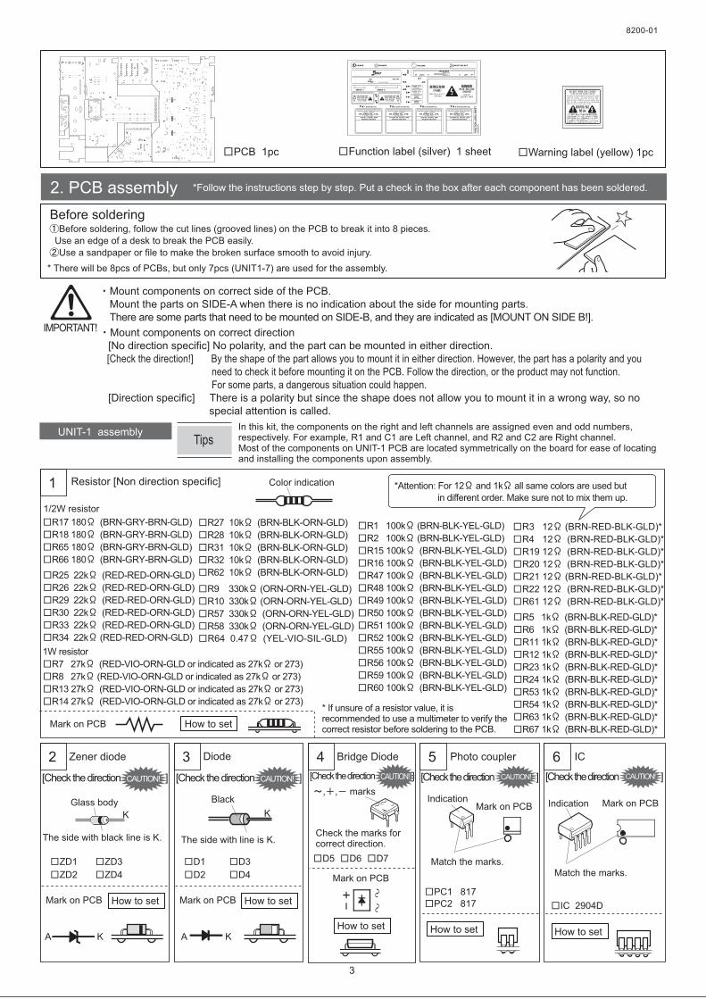
2. PCB assembly *Follow the instructions step by step. Put a check in the box after each component has been soldered.
Before soldering
Mount components on correct side of the PCB.
Mount the parts on SIDE-A when there is no indication about the side for mounting parts.
There are some parts that need to be mounted on SIDE-B, and they are indicated as [MOUNT ON SIDE B!].
Mount components on correct direction
[No direction specific] No polarity, and the part can be mounted in either direction.
[Check the direction!] By the shape of the part allows you to mount it in either direction. However, the part has a polarity and you
need to check it before mounting it on the PCB. Follow the direction, or the product may not function.
For some parts, a dangerous situation could happen.
[Direction specific] There is a polarity but since the shape does not allow you to mount it in a wrong way, so no
special attention is called.
UNIT-1 assembly
1 Resistor [Non direction specific]
2 Bridge Diode
R3 12 (BRN-RED-BLK-GLD)*
R4 12 (BRN-RED-BLK-GLD)*
R19 12 (BRN-RED-BLK-GLD)*
R20 12 (BRN-RED-BLK-GLD)*
R21 12 (BRN-RED-BLK-GLD)*
R22 12 (BRN-RED-BLK-GLD)*
R61 12 (BRN-RED-BLK-GLD)*
4
How to setMark on PCB
Mark on PCB
8200-01
How to set
Photo coupler5
Mark on PCB
How to set
, , marks
Zener diode
How to setMark on PCB
The side with black line is K.
Glass body Indication
Match the marks.
K
ZD1
ZD2
ZD3
ZD4
D5 D6 D7
PC1 817
PC2 817
Before soldering, follow the cut lines (grooved lines) on the PCB to break it into 8 pieces.
Use an edge of a desk to break the PCB easily.
Use a sandpaper or file to make the broken surface smooth to avoid injury.
Color indication
KA
TipsIn this kit, the components on the right and left channels are assigned even and odd numbers, respectively. For example, R1 and C1 are Left channel, and R2 and C2 are Right channel.Most of the components on UNIT-1 PCB are located symmetrically on the board for ease of locating and installing the components upon assembly.
Match the marks.
IC6
Mark on PCB
How to set
Indication
IC 2904D
Warning label (yellow) 1pcFunction label (silver) 1 sheetPCB 1pc
* There will be 8pcs of PCBs, but only 7pcs (UNIT1-7) are used for the assembly.
R5 1k (BRN-BLK-RED-GLD)*
R6 1k (BRN-BLK-RED-GLD)*
R11 1k (BRN-BLK-RED-GLD)*
R12 1k (BRN-BLK-RED-GLD)*
R23 1k (BRN-BLK-RED-GLD)*
R24 1k (BRN-BLK-RED-GLD)*
R53 1k (BRN-BLK-RED-GLD)*
R54 1k (BRN-BLK-RED-GLD)*
R63 1k (BRN-BLK-RED-GLD)*
R67 1k (BRN-BLK-RED-GLD)*
R25 22k (RED-RED-ORN-GLD)
R26 22k (RED-RED-ORN-GLD)
R29 22k (RED-RED-ORN-GLD)
R30 22k (RED-RED-ORN-GLD)
R33 22k (RED-RED-ORN-GLD)
R34 22k (RED-RED-ORN-GLD)
R1 100k (BRN-BLK-YEL-GLD)
R2 100k (BRN-BLK-YEL-GLD)
R15 100k (BRN-BLK-YEL-GLD)
R16 100k (BRN-BLK-YEL-GLD)
R47 100k (BRN-BLK-YEL-GLD)
R48 100k (BRN-BLK-YEL-GLD)
R49 100k (BRN-BLK-YEL-GLD)
R50 100k (BRN-BLK-YEL-GLD)
R51 100k (BRN-BLK-YEL-GLD)
R52 100k (BRN-BLK-YEL-GLD)
R55 100k (BRN-BLK-YEL-GLD)
R56 100k (BRN-BLK-YEL-GLD)
R59 100k (BRN-BLK-YEL-GLD)
R60 100k (BRN-BLK-YEL-GLD)
R9 330k (ORN-ORN-YEL-GLD)
R10 330k (ORN-ORN-YEL-GLD)
R57 330k (ORN-ORN-YEL-GLD)
R58 330k (ORN-ORN-YEL-GLD)
R27 10k (BRN-BLK-ORN-GLD)
R28 10k (BRN-BLK-ORN-GLD)
R31 10k (BRN-BLK-ORN-GLD)
R32 10k (BRN-BLK-ORN-GLD)
R62 10k (BRN-BLK-ORN-GLD)
1W resistor
R7 27k (RED-VIO-ORN-GLD or indicated as 27k or 273)
R8 27k (RED-VIO-ORN-GLD or indicated as 27k or 273)
R13 27k (RED-VIO-ORN-GLD or indicated as 27k or 273)
R14 27k (RED-VIO-ORN-GLD or indicated as 27k or 273)
1/2W resistor
R17 180 (BRN-GRY-BRN-GLD)
R18 180 (BRN-GRY-BRN-GLD)
R65 180 (BRN-GRY-BRN-GLD)
R66 180 (BRN-GRY-BRN-GLD)
3 Diode
How to setMark on PCB
The side with line is K.
Black
K
D1
D2
D3
D4
KA
*Attention: For 12 and 1k all same colors are used but
in different order. Make sure not to mix them up.
Check the marks for correct direction.
R64 0.47 (YEL-VIO-SIL-GLD)
[Check the direction ]CAUTION! [Check the direction ]CAUTION! [Check the direction ]CAUTION! [Check the direction ]CAUTION! [Check the direction ]CAUTION!
IMPORTANT!
* If unsure of a resistor value, it is recommended to use a multimeter to verify the correct resistor before soldering to the PCB.

[Check the direction ]CAUTION!
The LED leads must be bent to 90-degree
angle before mounting to the PCB. Place
the LED on top of the LED BENDING
TOOL marks on the PCB and carefully
bend the leads with fingers to a right
angle. Make sure to check
each lead length and set the
LED in the right direction.
Adjust the lead angle
with a long-nose plier
if not bent correctly.
4
7
9
CN7 4-pin
CN8 4-pin
CN9 6-pin
Q1 A1266or A1015
Q3 02N60Z
Q4 02N60Z
Q5 02N60Z
Q6 02N60Z
CN1 Pin header (male) 8-pin
V1 9-pin (black)
V2 9-pin (black)
V3 8-pin (white)
V4 8-pin (white)
J1
J2
J3
PTC
(Mustard, indicated as X10)
C3 0.1 F(400V)(Brown, indicated as 104)
C4 0.1 F(400V)(Brown, indicated as 104)
C9 0.1 F(400V)(Brown, indicated as 104)
C10 0.1 F(400V)(Brown, indicated as 104)
C1 220 F(16V)
C2 220 F(16V)
C5 220 F(16V)
C6 220 F(16V)
C13 220 F(16V)
C14 220 F(16V)
C33 220 F(16V)
C34 220 F(16V)
C35 220 F(16V)
C15 1 F(50V)
C16 1 F(50V)
C21 1 F(50V)
C29 100 F(50V)
C30 100 F(50V)
C31 3300 F(10V)
C32 3300 F(10V)
C7 10 F(400V)
C8 10 F(400V)
C11 10 F(400V)
C12 10 F(400V)
C23 10 F(400V)
C24 10 F(400V)
C25 10 F(400V)
C26 10 F(400V)
C27 10 F(400V)
C28 10 F(400V)
C22 180 F(420V)
8 Transistor
How to set
Mark on PCB
How to set
How to set
Mark on PCB
How to set
Mark on PCB
Mark on PCB
Mark on PCB
How to setMark on PCB
11 PTC
[Non direction specific]13
14
12 Film capacitor
[Non direction specific]
Connector
Pin header (male) 8-pin
[Non direction specific]
15 Connector
Box type VH connector
[Direction specific]
16 Jumper plug
LED
Electrolytic capacitor
Bend the leads here
to the opposite
direction to the
indication on the
FET at a right angle.
Fix it with a binding
screw long (M3x10)
and M3 nut to the
PCB.
Set the LED to the
location indicated
below. Make sure to
insert the longest
lead to the K
hole on the PCB
and solder.
Indication Longer leg is +.Indication
The side with white line is -.
Indication
The side with white line is -.
* Make sure to screw it
before soldering.
There are 6 holes.
Insert the leads to the 2 holes
at the center and solder.
UNIT-1 assembly
FET 10 Vacuum tube socket
Mark on PCB
Mark on PCB
Mark on PCB
Mark on PCB Mark on PCBHow to set How to set
How to set
Mark on PCB
Indication
E
M3 nut
E
C
C
B
B
Match the shape when mounting.
Solder it.
SIDE A
SIDE B
LED
FETBinding screw
long (M3x10)
Insert the socket from SIDE B and solder on SIDE A. Make sure the socket is fully
seated and flat against the PCB before soldering.
Sodering tip: Just solder 1 pin first, check if the socket is set at correct position,
and solder the remainig pins.
For 8-pin socket, check the setting direction as well. Check the hole shape at the
center, and match it with the indication on the PCB.
Insert the shorter side of pins to the PCB. Make sure that the pins are fully seated against the PCB before soldering.
Simply set the jumper plugs from SIDE B.
(No soldering)
Select the output tube operation mode with the jumper plug. "UL" is the most recommended mode. For detail, please see "8. Enjoy TU-8200 to the fullest". on Page17.
Select the power indication LED color from blue and green. Green is recommended as it is brighter than blue.
[Non direction specific]
SIDE A
SIDE B
SIDE A
SIDE B
Set them so that the
protrusion fits the hole.
How to set
Q2 A1266or A1015
Check the lead
length and
match the
applying side.
Bend to the right angle.
[Check the direction]
CAUTION!
[Check the direction ]CAUTION!
[Check the direction ]CAUTION!
[Check the direction ]CAUTION!
Insert the connector pins in the PCB and make sure they are fully seated against the PCB before soldering.
[Set on SIDE B, and solder on SIDE A! ]CAUTION!
[Check the setting side !]CAUTION!

5
1
4
JACK6
2 Film capacitor
[Non direction specific]
How to set
Mark on PCB6 7
8
L shaped metal bracket
3
VR
SW1 6-pin SW3 3-pin
LB1 L shaped metal bracket
CN2
CN10
CN3
How to setMark on PCB
* The attached nut and washer
will be used for assembly in
Step8. Do not discard.
3-pole standard jack
[Direction specific]
Connector
Pin socket (female) 8-pin [Non direction specific]
5 Toggle switch [Direction specific]
Mark on PCB Mark on PCB
Mark on PCB
How to set
How to set
Mark on PCB
Mark on PCB
How to set
How to set
How to set
How to set
R35 1k (BRN-BLK-RED-GLD)*
R36 1k (BRN-BLK-RED-GLD)*
R37 180 (BRN-GRY-BRN-GLD)
R38 180 (BRN-GRY-BRN-GLD)
R39 180 (BRN-GRY-BRN-GLD)
R40 180 (BRN-GRY-BRN-GLD)
R41 180 (BRN-GRY-BRN-GLD)
R42 180 (BRN-GRY-BRN-GLD)
R43 15
R44 15
UNIT-3 (PCB)
How to set
Mark on PCB
Mark on PCB
Color indication
Pan-head screw M2x5
Pan-head screw M2x5
Yellow
or
white1/2W resistor
2W resistor
* Attention!
The same colors as 12
are used for 1k
but in different order.
Make sure not to mix
them up!
Resistor [Non direction specific]
(indicated as 150 or 15 ,
or BRN-GRN-BLK-GLD)
C17 3300pF
C18 3300pF
Set the volume so that the shaft faces
outward.
Make sure the volume is fully seated against
the PCB before soldering.
* The pins may be bent.
Adjust them to match PCB holes
before mounting.
* The attached nuts and washers are
not used for SW1 and SW3. Please
either remove or tighten them so
that they do not get loose.
Make sure the jack is set
closely and horizontally to
the PCB upon soldering.
Make sure the switches are fully seated on
the PCB before soldering.
(50V)
(Indicated
as 332)
Solder the fixing pin as well.
Box type VH connector 2-pin
[Direction specific]
L shaped pin header (male) 40-pin
Set it on SIDE B of the PCB and solder on SIDE A.
[Check the setting side ]
Insert the bent leads to the PCB so that the straight
pins face outward.
Make sure that the header is set closely and
horizontally to the PCB upon soldering.
Fix with a pan-head screw
(M2x5). (No soldering).
Apply to the PCB matching to the
printing on the PCB, and fix
securely.
SIDE A
SIDE B
Insert UNIT-3 from above. Make sure
that the marks, and , on both PCB,
are matching.
Fix with a nut and a
washer for volume.
UNIT-3
Washer
for volume
Nut for volume
8200-01
UNIT-2 assembly
Volume
[Check the direction ]CAUTION!
[Check the direction ]CAUTION!
CAUTION!
[Check the direction ]CAUTION!
CAUTION![Check the direction ]
Insert Pan-head screw
M2x5 through UNIT-3
and L shaped metal
bracket hole and
tighten.

6
1 2 Connector
How to setMark on PCB
1 L shaped metal bracket
SW2 6-pin
JACK5
LB2
3 Toggle switch
[Direction specific]
[Check the direction ]
Mark on PCB How to set
How to set
R45 12 (BRN-RED-BLK-GLD)*
R46 12 (BRN-RED-BLK-GLD)*
CN4
CN5
CN6
How to setMark on PCB
Mark on PCB
Color indication
Pan-head screw M2x5
1/2W reistor
* Attention:
The same colors as 1k are used
for 12 but in different order. Make
sure not mix them up.
UNIT-4 assembly
UNIT-6 assembly
UNIT-5 assembly
Resistor [Non direction specific]
* The pins may be bent.
Adjust them to match the PCB holes before mounting.
Make sure the switches are fully seated against the
PCB before soldering.
1 3-pole mini jack
How to set
Mark on PCB
Make sure the mini jack is fully seated against
the PCB before soldering.
Set it to SIDE A so that the slot faces "GND" and
"LS" side on the PCB, and solder it on the same
side.
Solder the fixing pin
as well.
Fix it with a pan-head screw
M2x5.
(No soldering)
Match it to the PCB printing
and fix securely.
Set on the same side as the
resistors.
Insert the pins on the PCB so
that the slots face outward.
Make sure the connector is
set closely and horizontally
to the PCB upon soldering.
* Remove all the attached nuts and
washers. Only 1 nut will be used for
assembly later.
4 Film capacitor
[Non direction specific]
How to setMark on PCB
Yellow
or
white
C19 0.22 F
C20 0.22 F
(50V)(Indicated as 224)
2
Attach the previously assembled UNIT-6 to
UNIT-5 and fix with a pan-head screw M2x5
through L shaped metal bracket. (No soldering)
Make sure that the marks, and ,
printed on both PCBs, are matching.
Solder the 6 joints, "A" to "F",
of the 2 PCBs
UNIT-6
Pan-head screw
M2x5
UNIT-5
SIDE A
UNIT-6 [Direction specific]
Before soldering
After soldering
JACK1(WHITE) White
JACK2(RED) Red
JACK3(WHITE) White
JACK4(RED) Red
2 Pin jack
(RCA jack)
[Direction specific]
How to setMark on PCB
Make sure that the jack is fully
seated against the PCB before
soldering.
L shaped VH conenctor
3-pin
L shaped pin socket (female)
40-pin
CAUTION!
[Check the direction ]CAUTION!
[Check the direction ]CAUTION!

Before soldering
After soldering
7
3
CN12
FUSE
C36 RE1201 (Black)
UNIT-5 assembly
2 Connector
Box type VH connector 7-pin
[Direction specific]
Mark on PCB
Mark on PCBMidget fuse, fuse holder [Check the setting direction of the fuse holders ]
UNIT-4 [Direction specific]
* Make sure to select the correct
voltage for your region when
installing this connector to the PCB.
Verify before soldering.
In Japan, set to CN12.
4 Spark killer[Non direction specific]
How to set
Mark on PCB
8200-01
3
AC INLET
5 AC inlet
How to set
Mark on PCB
Nut (the one attached to the toggle switch) 1pc
1
Insert previously assembled UNIT-4
(SIDE A up) into UNIT-5 (SIDE A) slots.
Fix with the previously removed nut and
secure to the toggle switch threads on
SIDE B of UNIT-5.
(The washer is not needed.)
Make sure the marks, and , printed
on both PCBs, are matching.
Fix 2pcs of hex screw
spacers small (male-
female) on SIDE B of the
PCB with 2pcs of M3 nuts.
Set AC inlet to the spacers
and fix it with 2pcs of
M3x10 binding screws long.
Solder the 3 terminals of
the AC inlet on SIDE A of
the PCB.
Set the midget fuse to the
fuse holders as shown.
(No soldering)
Set the fuse holders to
the PCB and solder.
For the midget fuse, no
direction specific, but for
the holder, make sure
the setting direction.
Solder the 12 joints, "G" to "R" , of
the 2 PCBs.
In other countries...
110 - 120V(USA, Canada, etc) CN13
200V(Air conditioner in Japan, etc) CN14
220 - 240V(Many other countries) CN15
How to set
Mark on PCB
Make sure the connector is
fully seated on the PCB
before soldering.
Make sure the
connector is fully
seated on the PCB
before soldering.
Set it so that the protrusion
fits in the hole on the PC.
PCB (SIDE B)
M3 nut (2pcs)
Set it so that the protrusion
fits in the hole on the PC.
CN11 1pc
How to set
How to set
Connector
Box type VH connector 2-pin
[Direction specific]
UNIT-5
SIDE A
SIDE AUNIT-4
Remove 2 binding
screws used in for
temporary fixation.
Binding screw long M3x10
(2pcs) ... for temporary fixation
AC inlet
Hex screw spacer small
M3x18(male-female) (2pcs)
UNIT-7 assembly
CAUTION!
[Check the setting side ]CAUTION! [Check the direction ]CAUTION!

8
Completed PCB
R1 100k (BRN-BLK-YEL-GLD)
R2 100k (BRN-BLK-YEL-GLD)
R3 1
2(B
RN
-RE
D-B
LK
-GLD
)
R4 1
2
(BR
N-R
ED
-BLK
-GLD
)
R7 27k (RED-VIO-ORA-GLD(273))R8 27k
(RED-VIO-ORA-GLD(273))
R11
1k
(BR
N-B
LK
-RE
D-G
LD
)
R12 1
k(B
RN
-BLK
-RE
D-G
LD
)
R14 27k
(RED-VIO-ORA-GLD(273))
R15 1
00k
(BR
N-B
LK
-YE
L-G
LD
)
R16
100k
(BR
N-B
LK
-YE
L-G
LD
)
R21 12 (BRN-RED-BLK-GLD)R22 12(BRN-RED-BLK-GLD)
R25 22k (RED-RED-ORA-GLD)R26 22k (RED-RED-ORA-GLD)
R27 1
0k
(BR
N-B
LK
-OR
A-G
LD
)
R28 10k(BRN-BLK-ORA-GLD)
R31 10k(BRN-BLK-ORA-GLD)
R32 10k (BRN-BLK-ORA-GLD)
R33 22k(RED-RED-ORA-GLD)
R34 22k(RED-RED-ORA-GLD)
R29 22k(RED-RED-ORA-GLD)
R30 22k(RED-RED-ORA-GLD)
R47 100k(BRN-BLK-YEL-GLD)
R48 100k(BRN-BLK-YEL-GLD)
R49 100k(BRN-BLK-YEL-GLD)
R50 100k(BRN-BLK-YEL-GLD)
R51 100k(BRN-BLK-YEL-GLD)
R52 100k(BRN-BLK-YEL-GLD)
R53 1k(BRN-BLK-RED-GLD)
R54 1k(BRN-BLK-RED-GLD)
R55 100k(BRN-BLK-YEL-GLD)
R59 100k(BRN-BLK-YEL-GLD)
R56 1
00k
(BR
N-B
LK
-YE
L-G
LD
)
R60 1
00k
(BR
N-B
LK
-YE
L-G
LD
)R57 330k (ORA-ORA-YEL-GLD)
R58 3
30k
(OR
A-O
RA
-YE
L-G
LD
)
R61 12 (BRN-RED-BLK-GLD)
R62 10k(BRN-BLK-ORA-GLD)
R63 1k(BRN-BLK-RED-GLD)
R64 0.47
(YEL-VIO-SIL-GLD))
R66 180(BRN-GRY-BRN-GLD)
R67 1
k(B
RN
-BLK
-RE
D-G
LD
)
LED
ZD1A K
ZD4
A K
ZD3
A K
ZD2 A KD
1
D2
AK
AK
D3
AK
D4
AK
D5
D6
D7
PC1
817
PC2817
IC 2904D
Q1A1266
Q2A1266
E C B E C B
Q3 02N60Z
SD
G
Q5 02N60Z
SD
G
Q6 02N60Z
S DG
Q4 02N60Z
SD
G
PTC
C3 0.1 F(104)C4 0.1 F(104)
C9
0.1
F(1
04)
C10
0.1
F(1
04)
C2220 F
C710 F
C810 F
C1110 F
C1210 F
C14
220 F
C15 1 F
C161 F
C211 F
C2310 F
C2410 F
C2510 F
C2610 F
C27
10 FC2810 F
C29100 F
C30100 F
C313300 F
C323300 F
C35220 F
CN1
CN7CN8
CN9
V2 (SIDE B)
J1(SIDE B)J2S(SIDE B)
J3(SIDE B)
UNIT-3
R35 1
k(B
RN
-BLK
-RE
D-G
LD
)
R36 1
k(B
RN
-BLK
-RE
D-G
LD
)
R37 1
80
(BR
N-G
RY
-BR
N-G
LD
)
R38 1
80
(BR
N-G
RY
-BR
N-G
LD
)
R39 1
80
(BR
N-G
RY
-BR
N-G
LD
)
R40 1
80
(BR
N-G
RY
-BR
N-G
LD
)
R41 180 (BRN-GRY-BRN-GLD)R42 180 (BRN-GRY-BRN-GLD)
R43 1
5(B
RN
-GR
N-B
LK
-GLD
(150))
R
44 1
5(B
RN
-GR
N-B
LK
-GLD
(150))
C17
3300pF
(332)
C18
3300pF
(332)
VR
JACK6
SW1SW3
CN10
CN2
CN3 (SIDE B)
L shaped metal bracket
* For 100V AC use.
(Verify the correct voltage has
been selected for your region.)
FU
SE C
36
RE
1201
CN11
CN12(100V)
CN13(115V)
CN14(200V)
CN15(230V)
AC INLET (SIDE B)
* Are the screws for AC inlet used
for temporary fixation removed?
JACK5
JACK1 WHITE
JACK2 RED
JACK3 WHITE
JACK4 RED
R45 1
2(B
RN
-RE
D-B
LK
-GLD
)
R46 1
2(B
RN
-RE
D-B
LK
-GLD
)
C19
0.2
2F
(224)
C20
0.2
2F
(224)
CN5 CN6
CN4
SW2
C13220 F
UNIT-1
UNIT-2
UNIT-4
UNIT-6
UNIT-7
* Compare your PCB with below darwing and verify that the components are installed in the correct locations and the
correct direction.
Note: Double check for correct direction of the electrolytic capacitors, diodes, photo coupler, IC, transistor, and vacuum
tube sockets (8-pin).
Check the PCB for missing parts, unsoldered leads or pins, and bridged solder joints between components.
V4(SIDE B, check the socket direction!)
R18 180 (BRN-GRY-BRN-GLD)
V3 (SIDE B,
Check the socket direction!)
R17 180 (BRN-GRY-BRN-GLD)
R19 12(BRN-RED-BLK-GLD)
R23 1k(BRN-BLK-RED-GLD)
R5 1
k(B
RN
-BLK
-RE
D-G
LD
)
C1220 F
C5220 F
R9 330k (ORA-ORA-YEL-GLD)
V1 (SIDE B)
R13 27k
(RED-VIO-ORA-GLD(273))C6
220 F
R6 1
k
(BR
N-B
LK
-RE
D-G
LD
)
R10 330k(ORA-ORA-YEL-GLD)
R20 12(BRN-RED-BLK-GLD)
R24 1k(BRN-BLK-RED-GLD)
C34220 F
R65 180 (BRN-GRY-BRN-GLD)
C33 220 F
C22 180 F
Volume
Attached with a washer and a nut

9
PCB pattern * Compare your PCB with the PCB image below. Check for any unsoldered leads or pins, or an components with
insufficient solder, or bridged solder joints between leads/pins or components.
8200-01
SIDE A
SIDE B

10
1 2
3 4
3. Body assembly
Insert 4 speaker terminals to the holes from the
back side of the bottom chassis in the order of
RED-BLACK-BLACK-RED.
Assemble UNIT-5 (with UNIT-4 and 6).
Attach hex screw spacers - large.
* There are 2 M5 flange nuts attached to each terminal.
In this stage only 1 of them is used. The remaining ones
will be used in later step.
* Align the terminal holes so that the speaker wires can be
connected easily after assembly is complete.
M5 flange nut4pcs
Binding tapping screw
M3x10 4pcs
Masking felt
Attach output transformers.
Hex screw spacer - large
(M4x30 female-female)
4pcs
Low-head screw (M4x8) 4pcs
Bottom chassis
Terminal
Red
Red
Black
Black
Terminal
UNIT-6
Insulating bushing
Insulating bushing
Red or black
Insulating bushing
Red or black
Insulating ringM5 flange nut
4pcs
M5 flange nut
Place a masking felt (black) on the front of the toggle switch so
it is sandwiched between the switch and the hole in the chassis.
Set UNIT-5 to the bottom chassis so that the speaker terminals
fit through the holes of UNIT-5, and fix with 4pcs of binding
tapping screws at the pin jacks.
Fix UNIT-5 with the flange nuts at the speaker terminal screws.
UNIT-4
UNIT-5
Output transformer 2pcs
RED-YEL-ORN wire side
RED-YEL-ORN wire side
M4 flange nut 4pcs
Low-head screw (M4x8) 4pc
[Check the seting direction (wire color) ]CAUTION!

11
5 6
9 10
Set UNIT-7.
7 8
Low-head screw (M4x8) 4pcs
Power transformer
BLK-BRN-ORN
-WHT-GRY-YEL
wire side
RED-RED-YEL
-YEL-BLU-BLU
wire side
Insulator 4pcsLow-head screw (M4x8) 4pcs
Claw washer (M3) 2pcs
*Do not forget!
UNIT-7 Binding screw long (M3x10) 2pcs
Binding screw short
(M3x6) 1pc
Flat countersunk screw (M3x8) 1pc
Hex screw spacer - medium
(M3x22 female-female) 3pcs
Hex screw spacer - small
(M3x18 male-female) 3
Insert UNIT-2 connector (CN3) to UNIT-4 connector (CN4).
Attach UNIT-2 to the bottom chassis and fix with binding screw - short.
UNIT-2
Claw washer(M3) 3pcs* Do not forget!
Binding screw - short
(M3x6) 3pcs
BLK-GRN-GRY wire
Connect the left side wires to the left side of connector,
and the right side of wires to the right side of connector.
Attach the insulators.
CN3
CN4
Connect 3-pin connector of the output terminals
(BLK-GRN-GRY wire) to CN5 and CN6 of UNIT-4.
Attach the power transformer to the hex screw spacers set in Step3 and fix with 4 low-head screws.
Insert and connect screw hex spacers small and
medium to UNIT-2.
Attach UNIT-2 to the bottom chassis.
Hex screw spacer medium
(M3x22 female-female) 1pc
�
Set in the
order - .
�
8200-01
[Check the setting direction (wire color) ] CAUTION!

12
11 12
15 16
13 14
UNIT-7
UNIT-2
CN11
CN10
Connector cord
Connect 4-pin connectors
of the output transformers
(RED-YEL-ORN) to CN7
and CN8, to the closest
matching
connetor.
Connect 6-pin
connector of
the power
transformer
(RED-RED-
YEL-YEL-BLU-
BLU) to CN9.
UNIT-1 (SIDE A)
Connect UNIT-1 to UNIT-2. Make sure that CN1
pins are lined up correctly with the CN2 connector
pin holes.
Fix UNIT-1 with binding screws.
Binding screw short (M3x6) 3pcs
UNIT-1
UNIT-2
CN1
CN2
Claw washer (M3) 3pcs* Do not forget!
Binding screw short (M3x6) 3pcs
Binding screw short(M3x6) 4pcs
Screw for knob
Rotate with a hex wrench (1.5mm).
Knob
LED maskAttach the LED mask
on the back side of the
front panel over the
power indicator hole
and fix it with a scotch
tape.
Front panel
Tighten the screw
for knob so it seats
against the flat side
of the volume shaft.
Connect UNIT-7 and UNIT-2 with cords. Connect cords to UNIT-1.
Attach UNIT-1.
Place the LED mask on the back side of
the front panel.Install the knob onto the volume shaft.
Put the top chassis.
Fix with screws at 4 locations at the bottom.
(3 )
Fix with screwsat 3 locations at the back
Connect 7-pin connector of the power transformer (BLK-
BRN-ORN-WHT-GRY-YEL) to CN12 (or CN13-15).
Set top chassis.
Volume shaft
�
Install in the order of
,
�
�

13
17
19
18
Insert the tubes into the sockets.
Cut each label with a pair of scissors
Peel a small portion of the label backing off and cut with scissors so that the small portion of the label adhesive back is exposed.
Place the label in the desired location and attach it with the exposed adhseive.
Once the label is in the appropriate location, slowly remove the rest of the label backing to expose the rest of the adhesive.
* Select an appropriate label from K-1 to
K-4 according to the voltage setting you
selected in UNIT-7 assembly.
100V K-1
110 to 120V K-2
200V K-3
220 to 240V K-4
8200-01
Check the setting direction
of the tubes to the sockets.
6L6GCIf a tube has a base,
handle the tube by the tube
base when installing and
removing.
Base
Binding screw - short (M3x6) 3pcs
Masking feltMasking felt
Front panel
Complete!6L6GC
6L6GC
12AU7
(ECC82)
Tips
Attach the front panel. Apply the labels.
BottomTop
Back
A
G H
E
K*
J
B
DI
F
Make sure to attach this warning labelto avoid accident
Warning label (yellow)
�
�Set in the order of , and .
�
�

14
CAUTION
4. Safety precautions and safety check before and after powering up the amplifier (Be sure to read for safety use)
Incorrect use or handling of the product may cause electric shock, bodily harm, and damaged to the product and other
connected components. Please read the cautions below to avoid accidents.
Before closing the chassis after assembly or repair, make sure to verify that all the parts are installed correctly, there are no
mistakes in wiring and soldering before turning ON the power.
Electronic components in a vacuum tube amplifier exceed several hundred volts. To prevent electrick shock, do not remove
the top chassis when powered ON.
When operating the amplifier under a direct current (DC) by necessity (as to test the device), do not touch the parts,
terminals, and metal parts with bare hands. Make sure to wear a pair of gloves. Find a safe place away from others who
may come into contact with the amplifier while testing. Even when the power plug is pulled out, there is electricity remaining
in the capacitors. Make sure to wait at least 10 minutes after the power plug has been disconnected before touching any
components inside the amplifier.
If you find anything unusual while using the amplifier, immediately turn OFF the power and unplug the power plug from the
outlet, and refer to "Troubleshooting" on page15. If you cannot solve the problem, consult your local dealer or EK JAPAN.
Do not use the amplifier under an electric environment other than the preset power supply voltages. Normal household
current is Alternating Current (AC). Do not connect to a DC power supply.
When connecting and disconnecting the amplifiere with other devices, be sure to turn OFF the power and unplug the power
cord plug from the power outlet. Read the instruction manuals of the connected devices carefully and follow their
instructions.
When connecting or disconnecting the amplifier to/from other devices, make sure to have the power of all the devices
turned OFF. Failing to do so may cause damage to the amplifier and connected devices.
Before turning ON, switching inputs, or plug/unplug the headphone terminal, turn the volume control to minimum in order to
prevent sudden bursts of high volume that may cause auditory disorder or speaker and headphone damage.
Adjust the sound volume slowly to an appropriate level, especially with headphones, to prevent sudden burst of high
volume that may cause ear injury and auditory disorder.
During operation, the vacuum tubes become very hot (over 100 degreeC). Do not touch them with bare hands to avoid
burn injury. Even after the power is OFF, it takes several minutes for the vacuum tubes to cool down. Make sure not to
place the amplifier where children can reach it.
If water or any unwanted substance gets into the main body of the amplifier, immediately turn OFF the power and unplug
the AC power cord. Wait for at least 10 minutes, open the chassis and remove/wipe off the substance, and consult with
your local dealer or EK JAPAN. Failing to do so may cause failure, fire, or electric shock.
Hold onto the AC plug or connectors when unplugging. Do not unplug by yanking the AC power cord, as it may cause
potential injury, fire, or electric shock.
Do not put heavy items on or under the AC power cord. Do not place the amplifier near any source of heat, such as a
heater. Doing so may damage the AC power cord and cause fire or electric shock. Do not use damaged AC power cord.
Do not plug/unplug AC power cord with wet hands. Doing so may result in electric shock.
Handle the amplifier gently, especially the vacuum tubes as they are made of glass.
Place the amplifier on a stable surface to avoid a falling hazard. Place the amplifier in a location where nothing could fall
onto the amplifier.
Keep out of direct sun, extreme hot and cold, humid or dusty areas as they may cause accidents and damage. Do not
allow gas or corrosive substances to come into contact with the amplifier. Failing to do so may cause damage or hazard.
Make sure the amplifier is placed at least 10cm away from walls, and has at least 10cm of space above it as well, as the
amplifier will radiate heat. Placing the amplifier too close with other equipment may cause a fire. Do not place the amplifier
on a thick carpet, or in an enclosed space such as a drawer, or a box that will obstruct ventilation. Do not cover the
amplifier with table cloths, towels, pillows or anyting that may cause fire.
Clean the amplifier regularly. If dust accumulates on the circuit board, it may cause fire or other hazards. It is recommended
to clean the amplifier before the start of humid or rainy seasons.
The amplifier is designed for home use. Do not use it in environments that it would push the amplifier beyond it's limitations.
Discard the amplifier according to the rules and standards in your region. Failing to do so may cause damage to the
environment and others.

15
Symptom Check point
6. Troubleshooting
Turn OFF the power (lever down) and have the sound volume to the minimum (fully to the counter-clockwise direction).
Refer to "7.Connection" on page16 and connect the sound source, speakers, and AC power cord. Connect a sound source to INPUT 2 and push the
input selection switch lever down. Make sure the correct speaker impedance is selected on the back of the amplifier to match the speakers being
connected.
Turn ON the power (lever up) and make sure that the pilot lamp right under the power switch turns green (or blue according to your setting).
Make sure that the heaters inside all the 4 tubes slowly turn orange.
Wait for 30 minutes, and if everything is OK, play a music from the connected sound source and slowly turn up the volume (to clockwise direction).
Confirm that the sound is output normal from both right and left speakers.
Turn the volume down (turn the knob to the counter-clockwise direction), connect a pair of headphones, and turn up the volume. Make sure that the
sound output is only from the headphones and no sound is heard from the speakers.
Turn OFF the power, unplug the headphones, connect a sound source to INPUT 1, push the input selection lever up, and do the above steps 3 to 7
again. (If you do not have a patch cord to connect to INPUT 1, skip.)
If all of the above operation checks are OK without any problem, operate the amplifier for 30 minutes at low/no volume to confirm the proper
operation. During this period, be aware of any burning odors, unexpected noises (hums, popping, static, etc). When you face a problem, unplug
immediately and use the below troubleshooting steps to resolve.
Please refer to the below troubleshooting steps upon use or during operation check.
If you cannot solve the problem, please consult with your local dealer or EK JAPAN.
Will not turn ON when the power
SW is turned ON (The LED pilot
lamp and the tube heaters will not
turn ON either.).
Is the AC power cord plugged on both ends securely?
Is the AC power cord damaged?
Is the connection of the connector inside, especially CN9 to 15, secure?
Is the soldering of SW3, CN10, and inside UNIT-7 secure?
Is the midget fuse blown?
The LED pilot lamp turns ON but
a/some tube heater/s are not glowing.
Check the soldering condition of the socket of the tube that does not turn ON. Also check the
soldering and setting of R64, C31 to 32, D6, and CN9.
The operation is normal but the pilot
lamp does not turn ON (or turns ON
in a color other than green or blue.).
There is a problem in the circuit just around the LED. Check for the correct orientation of the
LED, whether J3 is set (P4), or the soldering condition of LED and R62.
Either right or left channel has a
problem.
Swap right and left tubes and see if the symptom follows the tube. If so, it is attributed to tube itself. If not,
the problem is in the circuitry.
When there is a problem in the circuitry, check all circuits in the problematic channel, except for UNIT-7.
Odd number components are assigned to the left channel, and even numbers for right channel.
Are the cords, such as input and speaker output, connected securely? Check the cord for broken or torn
sheathing.
* If the pilot lamp is red, orange, or any reddish color when there is no sound, the problem detection circuit of the
output tubes is active. Follow the same checks listed above.
Difference in volume between the
right and left channels.
If this occurs at low volume levels, (when the volume knob is at 7-8 o'clock position), it is due to the
specification of the volume control (deviation between right and left) and it is normal. Try decreasing the
volume on the audio input source.
When the problem occurs regardless of the volume position, do the same checks as above step . If
there is a problem in the circuitry, the smaller volume channel may be normal and louder volume channel
may be abnormal. Check the components of both channels for correct placement and soldering.
A loud hum can be heard through
speakers/headphones at the
lowset volume setting.
When using very high-efficiency headphone, you may hear a hum that cannot be heard
through speakers. Removing R39 and R40 may improve hum.
If the hum is heard through the speakers or there is a big hum difference between the right
and left channel, there may be a problem in the ripple filter circuit of power B. Check the PCB,
focusing on Q3 to Q6, ZD1 to 4, D1 to 2, PC1 to 2, R47 to 60, and C22 to 28.
A hum is heard when the volume is
turned up.A problem is not with the volume control. Check the soldering condition of SW1, CN1 to 4,
JACK1 to 5, and UNIT-4,5,6. Also, check the AC power cord for damage and torn sheathing.
The vacuum tubes become very hot. Tubes work when heated, and when it is heated, especially the output tubes, 6L6GC in this
device, it becomes very hot, over 100 degreeC, as it deals with high electric power. So DO
NOT TOUCH THE TUBES WHEN THEY ARE HOT. * However, it is abnormal when the tube plate, the
outmost electrode, start glowing red and hot. Immediately turn OFF the power.
When a tube is tapped, the tap is
amplified and heard through the
speakers.
The noise is called "microphonic noise" inherent in tube amps. Microphonic noise occurs by the
electrode of the tube picking up oscillations. Oscillation affects the sound quality, so it is recommended
to place a tube amp in a location where it will not pick up external oscillations (away from speakers).
Difference in the brightness of the
heaters of the right and left tubes,
The heater of the tube is to heat up the cathode electrode, and the excess heat is seen as the
glow of the heater. The brightness of the heater glowing will varyfrom tube to tube. It has
nothing to do with tube quality.
In low light condition luminous blue
glow can be seen inside the
output tubes (6L6GC) .
This is called "blue fluorescence" that occurs when the electrons hit the glass surface and
illuminate. Blue fluorescence will vary from tube to tube. In some tubes blue fluorescence will occur
but fade over time, and others may never exhibit it. It has nothing to do with tube quality.
5.Operation check *Check the amplifier in the following order.
Turn the amplifier OFF immediately if there is anything not in order during the operation check.
8200-01

16
4.
7. Connection
* Cords and cables to connect speakers and any sound source device is not included.
Please use your own cords and cables for attaching to the amplifier.
Make sure to turn OFF the power of all the devices before connecting/disconnecting cords.
Stationary CD player, etc
R L
Stereo RCAplug cord
Dock cable for your music player
Portable music player
* It is possible to connect to the headphone output of your portable music player with a 3-pole mini plug cord (without resistor), but using a docking cable is recommended for better sound quality.
INPUT1 INPUT2
Right SP Left SP
Speaker impedanceselection SW
Select according to the impedance of your speakers.
Left speakerRight speaker
BACK
FRONT
* The speaker terminals correspond to banana plug as well.
8 to 16
4 to 6.3
AC INLET
AC cord
Plug intooutlet
If the outlet is equipped with a terminal, connect the ground terminal to it.
Pilot lamp
Power SW
ON
OFF
Headphone output jack
Approx. 8 to 1kcan be used.
Volume
Input SW
INPUT 1
INPUT 2Headphone
When the amp is used outside Japan,
make sure to set the VH connector to
appropriate position in Page7 according
to your local voltage environment, and
use a plug converter that matches the
outlet of your residence.
CAUTION!
* If a problem occurs around the
output tube and the circuit around it
while the power is ON, and
overcurrent occurs, the protective
circuit becomes active, and shuts
down the B power of the
problematic circuit (there will be no
sound.). Then the pilot lamp turns to
reddish color (orange-red-purple).
INPUT2 is equipped with RCA jack and 3-pole mini jack. 3-pole mini jack has priority when connected to both.

17
8200-01
8. Enjoy TU-8200 to the fullest
* We are not liable or responsible for any problems/failures caused by component exchange or modifications, and kindly
ask you to conduct such component exchange and modification at your own risk and responsibility.
* We do not provide the capacitors and tubes for exchange. Please purchase them from reputable electronic or vacuum
tube vendors.
Triode and pentode are 2 most common configurations in audio vacuum tube amplifiers. The difference in triode and
pentode modes offer the audio enthusiast 2 very different listening experiences.
Pentode mode provides high efficiency and power, but some audio enthusiasts believe triode mode surpasses pentode
mode in sound quality. The TU-8200 has a jumper that can easily change the amplifier's mode from triode to pentode. In
addition, an intermediate mode called "Ultra Linear" can be selected. In this UL mode, you may obtain high efficiency
similar to pentode mode and sound quality of triode mode.
In this amplifier, you can select from the 3 modes, Pentode, UL, and Triode, simply by changing the jumper plug J1 and
J2 on SIDE B of UNIT-1.
Various vacuum tubes manufacturers make the same model or equivalent of a tube. You can find different brands of
same model tubes from various tube vedors. Although the model numbers are the same, tubes from different
manufacturers will have variations in the way they sound. The ability to expreience different sounds by changing tubes
is one of the real thrills of tube amplifiers.
When changing the 6L6GC power tubes, make sure the replacement 6L6GC version is the equivalent of the 6L6GC.
Some 6L6 variants will not have the "GC" designation and have lower power ratings. These cannot be used in the TU-
8200.
For 12AU7, it is possible to use those with additional letters at the end, such as 12AU7 or 12AU7WA. ECC82 is the
European model number for 12AU7, so it can be used as 12AU7. (Please note that 12AX7(ECC83) and 12AT7(ECC81)
have larger property and cannot be used for TU-8200.)
There are many output tubes that have similar properties and pin layouts to 6L6GC. These other output tubes all have
unique and different sound qualities compared to 6L6GC in the above
Traditionally, when other variations of output tubes are used, it is usually desirable to modify the circuits. However, with
TU-8200, a new function "Active automatic Bias" is adopted so that the bias is automatically adjusted when the tubes
are switched. You can enjoy the best performance of various tubes, such as KT88, KT66, KT90, 6550 and
EL34(=6CA7), without any adjustment to the amp. (Please note that 6V6 family is unusable with TU-8200.)
General attributes of output tubes;
- 6L6GC and equivalent: Very balanced, with clear highs
- KT88 and equivalent: Powerful bass, and strong midrange with clear highs
- EL34 and equivalent: Delicate, beautiful, and brilliant highs
* The circuit around the jumper plug has high voltage and it is dangerous to touch the PCB without caution. Make sure to turn OFF
the power and unplug the AC power cord, then wait for at least 10 minutes before changing the jumper connection. Also, changing
the connection while the power is ON could damage the tubes and the output transformers. Therefore please refrain from
modifying the amplifier, such as adding a switch to change the connection.
Enjoy the difference in sound by changing the operation modes of the output tube
Try different brands tubes that are the same model number (tube rolling)
Try other output tubes
In some instances, switching some of the components with higher grade components may improve the sound.
Capacitors are one of those that affect the sound. However, switching to whatever capacitors randomly may not improve
the sound, or may even cause problems. Here are some guidelines for exchanging the capacitors for better sound
quality.
1. Exchanging the cathode bypass capacitors with coductive polymer aluminum solid electrolytic capacitors with low
ESR is very effective. In this amplifier, the 4 capacitors of C1, C2, C5, and C6 are used as cathode bypass capacitors.
By default they are 220 F 16V aluminum electrolytic capacitors. If you exchange, make sure the value is between 150
to 220 F, and the rated voltage is 10V.
2. Coupling capacitors affect the sound as well. In this amplifier, the PCB is designed with some extra space around C3,
C4, C9, and C10 so that users can exchange those coupling capacitors with different ones of larger size. However,
those originally included are non-inductive polypropylene film capacitors that can cover high frequency. Therefore you
may not hear the effect even after they are exchanged.
If replacing these capacitors, the value shall be higher than 0.1 F, and the rated voltage should be minimum of 400V.
Please make sure to select one which can fit in the provided space on the PCB without interference with other parts.
Change the capacitors in search of your favorite sound

18
9. What attracts people about vacuum tubes?
10. Technical data
In former times,vacuum tube used to be adopted for every electronic circuit found in radios, TVs, communication
broadcasting devices, sound amplification and computers. However, rise of semiconductors almost wiped them out in a
moment. Although vacuum tubes are no longer found in most elctronic devices, they have a strong following and are
popular amongst audiophiles in sound amplification. A solid state amplifier shows almost ideal measured values
whereas a vacuum tube amplifier have high level of noise and distortion. From a viewpoint of measured values, a
vacuum tube amplifier must be obviously inferior to a solid state amplifier. So why is it said to have a better sound
quality?
The biggest factor is that the vacuum tube characteristics curve is quadratic function by which a vacuum tube produces
a distortion so called second harmonic. The second harmonic is a frequency double the original sound, and an overtone
factor which are abundantly produced by various musical instruments and gives depth and richness to the sound.
Product & Model No.
Circuit configuration
Stock tube
Rated output
Rated input
Residual noise
Frequency response
Speaker impedance
Headphone impedance
Output terminal
LINE-IN terminal
Power
Power consumption
Dimensions
Weight
6L6GC Single Tube Amp Kit, TU-8200
Tube single operated stereo power amplifier
All tube practice amplifier for signal related
Output operation mode can be selected by changing the jumper plug location:
Ultra Linear connection, Pentode connection, Triode connection
Active automatic bias adjustment circuit on board
MOSFET B power ripple filter on board (right and left separately)
Output tube overcurrent protection circuit on board (right and left separately)
[Output tube] 6L6GC x 2, [Voltage amplifying tube] 12AU7(ECC82) x2
(For output tubes, EL34(6CA7), KT88 and equivalent can be used.)
8W + 8W(6L6GC, UL connection)
8.2W + 8.2W (6L6GC, pentode connection)
4W + 4W (6L6GC, triode connection)
340mV (6L6GC, UL connection)
90 V (IEC WEIGHTING)
12 to 50,000Hz( 3dB)
4 to 16 (switching either 4 to 6.3 or 8 to 16 range)
8 to 1k (corresponds to high impedance speakers), unbalance
Speaker output: Gold-plated binding terminal (banana plug is also usable)
Headphone output: 3-pole standard jack ( 6.4mm)
RCA jack stereo 2 lines (INPUT 1, INPUT 2)
3-pole mini jack ( 3.5mm) 1 line (INPUT 2 side, 3-pole mini jack has priority.)
100VAC, 50/60Hz (select from 100V, 115V, 200V, and 230V upon assembly)
IEC standard 3P inlet type
60W (6L6GC)
85W (KT88)
W252 H156 D285 mm (when stock tubes are mounted, including projections)
Approx.6.6kg (assembled, excluding AC cord)
Specifications
The specifications, forms and contents of this product are subject to change for improvement without prior notice.
8 loaded
On the other hand, the distortion produced by a solid state
amplifier is mostly the multiples of odd numbers, such as
tertiary and quintic. Therefore a sound different from the
original sound is produced, which is unpleasant to listeners.
This is why there are various countermeasures taken for a
solid state amplifier to lessen the distortion to have it close
to zero as much as possible.
Although a vacuum tube amplifier may not match a solid
state amplifier in terms of measured audio specifications,
the quality of the sound produced by its distortion is
superior to that of a solid state amplifier and attracts many
audiophiles.
Image of distortion
(Triode tube)
Image of distortion
(Solid state)
Ground note
7th harmonic
5th harmonic
3rd harmonic
2nd harmonic
:
:
:
:
:
:
:
:
:
:
:
:
:
:
:

19
Circuit diagram
8200-01
PointStandard Voltage
(DC, GND)
A
RIPPLE
RIPPLE

20
11. Warranty
Since this is an electronic product assembled by a user, EK JAPAN cannot provide a standard warranty like those found with a regular electronic product. Instead, EK JAPAN can provide help to resolve your problems via troubleshooting support from your local EK JAPAN dealer or you can e-mail EK JAPAN directly. If you experience problems with the assembled product, please contact an EK JAPAN dealer in your region or the store from where you purchased the product for further assistance. If you do not know who to contact, please send us an e-mail describing the problem you are facing to the e-mail address below. Throughout the instruction manual, there are many check points, and in many instances the problem can be solved if you review these points closely, and use the troubleshooting on Page 15 before consulting to your dealer or EK JAPAN.
Contact information
EK JAPAN CO.,LTD.
Tofuro-minami 2-19-30, Dazaifu-shi, Fukuoka, 818-0105, Japan
Phone: +81-92-923-8235
Fax: +81-92-923-8237
Website: http//www.elekit.co.jp
E-mail: [email protected]
1.ELEKIT is a registered trademark of EK JAPAN CO.,LTD.2. All rights reserved. Reprinting any of this instruction manual without permission is prohibited. 3. The specifications, forms and contents of this product are subject to change without prior notice. 4. We do not accept any responsibility for disadvantage or damage caused by improper use or assembly.
C EK JAPAN CO.,LTD. 2014
ATTENTION