
TTT_8051_PPT
109
8051 Architecture
description
nn
Transcript of TTT_8051_PPT

8051 Architecture

Tessolve Training Development Institute
8051 hardware architecture components
� Hardware architecture components of 8051 are
� 4K bytes ROM
� 128 bytes RAM
� Four 8-bit I/O ports
� Two 16-bit timers
� Serial Interface
� 64K external code memory space
� 64K external data memory space
� Boolean processor

Tessolve Training Development Institute
Block diagram
Interrupt control
CPU
Oscillator Bus Control I/O PORTS Serial Port
Timer 1
Timer 0
Timer 2 (8052) ROM
0K-8032
4K-8051
8K-8052
CPU
Other Registers
/EA RST ALE /PSEN
P0 P1 P2 P3
RXD TXD
T0
T1
T2
/INT0
/INT1
XTAL
Timer 0
Timer 1
Serial

Tessolve Training Development Institute
Pinout
PDIP
(RXD)P3.0(TXD)P3.1
(T0)P3.4(T1)P3.5
XTAL2
GND
(INT0)P3.2(INT1)P3.3
(RD)P3.7(WR)P3.6
1234567891011121314151617181920
4039383736353433323130292827262524232221
P1.0P1.1P1.2P1.3P1.4P1.5P1.6P1.7RST
XTAL1
VccP0.0(AD0)
P0.1(AD1) P0.2(AD2) P0.3(AD3) P0.4(AD4) P0.5(AD5) P0.6(AD6) P0.7(AD7) EA/VPPALE/PROG
PSENP2.7(A15) P2.6(A14) P2.5(A13)
P2.4(A12) P2.3(A11) P2.2(A10) P2.1(A9) P2.0(A8)
8051

Tessolve Training Development Institute
GPIO ports
� Port 0:
� General purpose I/O
� For external memory:
Multiplexed Address/Data bus
� Port 1:
� General purpose I/O
� Port 2:
� General purpose I/O
� For external memory: High-Order Address
� Port 3:
� General Purpose I/O
� Alternative function pin

Tessolve Training Development Institute
GPIO ports...
� External device interfacing
� EA - External Access
� ALE - Address Latch Enable
� PSEN – Program Store Enable
� WR – Write Enable
� RD – Read Enable
� PSEN – Program Store Enable
� Output signal on pin 29
� Used to enable external code memory when accessing external ROM
� Low to enable OE’ on external ROM

Tessolve Training Development Institute
GPIO ports...
� P3 is shared with control lines
� Serial I/O RxD, TxD,
� external interrupts INT0,INT1
� Counter control T0, T1
1717RDRDP3.7P3.71616WRWRP3.6P3.61515T1T1P3.5P3.51414T0T0P3.4P3.41313INT1INT1P3.3P3.31212INT0INT0P3.2P3.21111TxDTxDP3.1P3.11010RxDRxDP3.0P3.0
PinPinFunctionFunctionP3 BitP3 Bit

Tessolve Training Development Institute
GPIO ports...
� ALE – Address Latch Enable (pin 30)
� Used to latch the low order address byte on port 0 when accessing
external memory – RAM or ROM
� Pulses 1/6th of the oscillator clock
� EA’ – External Access
� When tied HIGH, Memory 0 –4K code memory is accessed from internal
ROM
� When tied LOW, external memory is used for all code access
� Must be tied low for the 8031/32
Tessolve Training Development Institute
GPIO ports...
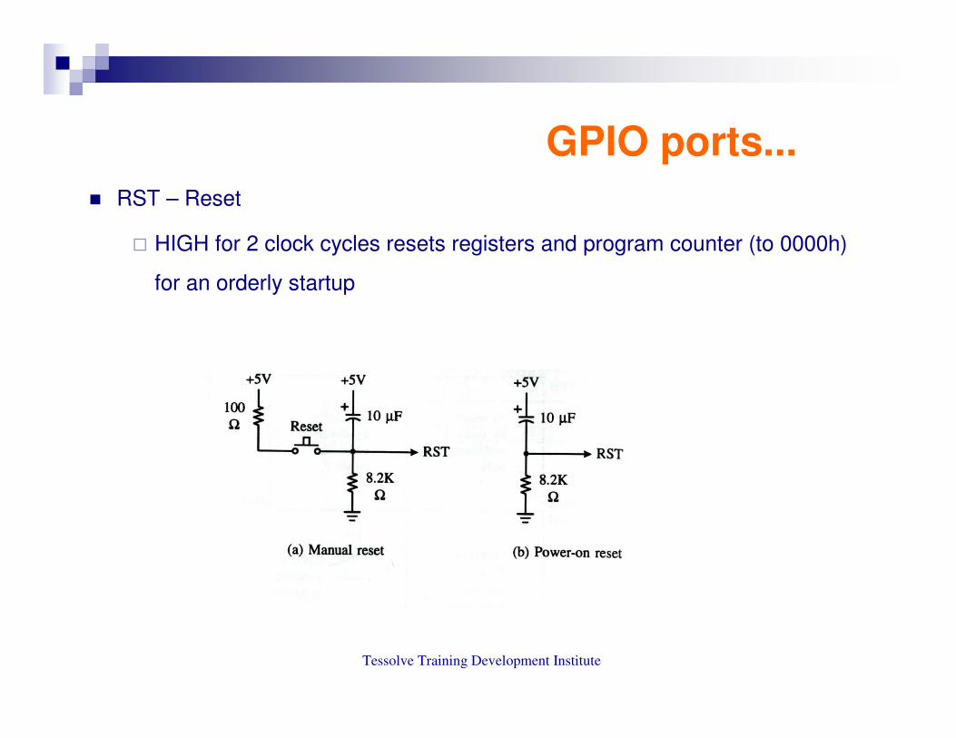
� RST – Reset
� HIGH for 2 clock cycles resets registers and program counter (to 0000h)
for an orderly startup

Tessolve Training Development Institute
GPIO ports...
� XTAL1, XTAL2 – Oscillator inputs
� 12MHz typically for the 8051
� Class use 11.059Mhz
� Power +5V for Vcc and 0V Ground
� Original 8051 uses 12 sysclk cycles per “machine cycle”
Input
circuit
sysclk

Tessolve Training Development Institute
Registers
A
B
R0
R1
R3
R4
R2
R5
R7
R6
DPH DPL
PC
DPTR
PC
8051 16-bit Register
8051 8-bit Registers

Tessolve Training Development Institute
Registers...
•A (Accumulator) - Primary register for byte operations such as math and logical
operations
•B - Used along with the Accumulator for multiplication/division
�PSW(Program Status Word) – contains math flags,user program flag,register
banks select etc
�SP (Stack Pointer)
� Points to the Internal RAM address called as 'top of the stack’
� Addresses and data are ‘pushed’ onto the stack and ‘popped’ off, last-in first-
out (LIFO)

Tessolve Training Development Institute
Registers....
� PC (Program Counter)
� holds the address of a byte in memory(Program ROM)
� PC is automatically increments after every byte fetch
� DPTR (Data Pointer)
� Made up of two register DPH and DPL
� Used to furnish memory addresses for Internal,External code and External
data access
� RD and WR I/O’s are used to determine data direction

Tessolve Training Development Institute
Registers...
1F
18
0706050403020100
R7R6R5R4R3R2R1R0
0F
08
17
10
Bank 3
Bank 2
Bank 1
Bank 0
Four Register Banks
Each bank has R0-R7

Tessolve Training Development Institute
Memory
� Harvard Architecture
� Separate Code and data memory
� Both code and data memory may be internal
� Expanded to have up to 64K of code memory using external components
� Expanded to have up to 64K of data memory using external components
� Notable features
� Registers and I/O ports are memory mapped
� Stack lies within the RAM

Tessolve Training Development Institute
Memory...
� On chip Data memory
General Purpose RAM

Tessolve Training Development Institute
Memory...
20h – 2Fh (16 locations X 8-
bits = 128 bits)
0001020304050607
080F
10
1A
787F
27
26
25
24
23
22
21
20
2F
2E
2D
2C
2B
2A
29
28
Bit addressing:
mov C, 1Ah
or
mov C, 23h.2
� Bit Addressable memory

Tessolve Training Development Institute
Memory...� Special Function registers
� 21 special function registers
� 11 SFR's are bit addressable

Tessolve Training Development Institute
Memory...
� External Memory
� Useful when expanded ROM, RAM or I/O must be used
� Can address up to 64K of external memory
� Port 0 is multiplexed for both address (Low byte) and memory
� Port 2 is High Address Bus
� ALE, PSEN, RD,WR are used for control

Tessolve Training Development Institute
Memory...� Interfacing External ROM

Tessolve Training Development Institute
Memory...
� External RAM
� External RAM memory location can be accessed using MOVX instruction:
� The DPTR register for 64K access
� Using RO or R1 for 256 byte access
� Address is placed on Port 0 (and port 2)
� ALE latches in low address
� Data is placed on Port 0,WR goes low to write to RAM
� RD goes low to enable RAM output,Port 0 Reads data

Tessolve Training Development Institute
Memory...
� Interfacing External RAM

I/O PORT Programming

24Tessolve Training Development Institute
8051 Ports� All four ports are 8 pin ports and bidirectional. � Each port pin can be independently used as an input or an output.
� All the ports upon RESET are configured as inputs.� Ports 0 and 2 have dual role
� Port 0-GPIO or Address /Data bus� Port 2-GPIO or Address bus
� Ports 0 and 2 may not be used as general purpose I/O when it is being used as the ADDR/DATA BUS.
� Port 3 has additional functions .By default P3.X pin level is the pin’s alternate input function.
� Each port pin consists of a latch (SFRs P0 –P3), an output driver and two input buffers.
� To make a port as input, the port bit latch must contain 1.
� Ports 1,2, and 3 have internal pull ups. Port 0 has open drain outputs.

25Tessolve Training Development Institute
Output Pin - Writing “1” to P1.X
1.Write a 1 to the pin
2. output pin is
Vcc
output 10
1

26Tessolve Training Development Institute
Output Pin -Writing “0” to P1.X
1.Write a 0 to
the pin2. Output pin is 0
Output 0
0
1

27Tessolve Training Development Institute
Input Pin -Reading “High”
1. Write a 1 to the pin
MOV P1,#0FFH
2. MOV A,P1
external pin=High
3. Read pin=1 Read
latch=0 Write to latch=1
11
0

28Tessolve Training Development Institute
Input Pin -Reading “Low”
1. Write a 1 to the pin
MOV P1,#0FFH
2. MOV A,P1
external pin=Low
3. Read pin=1 Read
latch=0 Write to latch=1
01
0

29Tessolve Training Development Institute
A pin at Port ‘0’
� Dual Role of Port 0
� To interface with external memory it acts as address and data lines i.e AD0 – AD7
� Can be used as a GPIO

30Tessolve Training Development Institute
Port 3 additional function details
� Port 3
� Port 3 can be used as input or output
� Port 3 has the additional function

31Tessolve Training Development Institute
Ports SFRs
� All ports are bit addressable
� Set bit 1 in this register ,the
corresponding pins will be acted as
input pins.

32Tessolve Training Development Institute
Programming I/O ports
�Programming I/O ports using Embedded C
� Data types Revisited

33Tessolve Training Development Institute
Manipulating bits in memory
� manipulation of bits by macros or function
� Mostly uses the bit wise operators of C

34Tessolve Training Development Institute
Manipulating bits in memory� Bit wise operators

35Tessolve Training Development Institute
Manipulating bits in memory� Boolean vs bitwise operators

36Tessolve Training Development Institute
Manipulating bits in memory� Interpreting the bit wise AND

37Tessolve Training Development Institute
Manipulating bits in memory
� Interpreting the bit wise OR

38Tessolve Training Development Institute
Manipulating bits in memory� Interpreting the bit wise XOR

39Tessolve Training Development Institute
Testing bits
� Bit wise AND
� To test the value of a single bit
� 'mask value ' is '1'
� The operand is bit wise ANDed with Mask value
� result will be non-zero if and only if the bit of interest is '1'
� Eg., if ((bits & 64) = 0) /* to test whether the 6-bit is set */
� Better way, If (bits & 0x0040)
� Best way, if (bits & 1<<6)

40Tessolve Training Development Institute
Setting and clearing bit � Setting a bit
� Accomplished using bit wise OR-operator
� E.g., bits = bits | (1<<7 ); /*Set bit 7*/
� Other way: bits |= (1<<7) ;
� Clearing a bit
� Accomplished using bit wise AND-operator
� Mask value is '0'
� Bits &= ~(1<<7); /*Clear bit 7*/
� If bits is 32 bit long
� right side of the assignment should also be of same length i.e Bits &= ~(1L<<7);

41Tessolve Training Development Institute
Inverting bit
� Called toggling
� Accomplished using bitwise XOR operator
� E.g., bits ~= (1<<7);
� Correct Usage
� Bits ^= (1<<7); /* toggle the bit 7*/

42Tessolve Training Development Institute
Extracting bit
� Extracting value of the bit fields
� shifting to right
� ANDing with mask

43Tessolve Training Development Institute
�Sample Program #1 --Send value from 0 to 255 to port 1
I/O port Programming Example 1

44Tessolve Training Development Institute
�Sample Program #2-- Toggle bit D0 of the port P1 (P1.0) 50,000 times
I/O Programming –Example 2

45Tessolve Training Development Institute
I/O Programming –Example 3
� Sample program #3 --- To port bits of P1 forever with delay

46Tessolve Training Development Institute
Summary
� 8051 has four 8-bit I/O ports .
� P3 has special function pins .
� P0 and P2 are used in interfacing the External memory .
� Pull-up resistor is must for the Port 0 .
� On Reset all the port is configured as input.
� All the I/O port pins are bit addressable.
� Choose the appropriate 'mask'
� Choose the appropriate 'bitwise' operator
� Match the left hand and right hand data types

8051 Timer -counter

48Tessolve Training Development Institute
Introduction to Timer
• The 8051 has two timers/counters
– Timers to generate a time delay or as
– Event counters to count events happening
outside the microcontroller
• Both Timer 0 and Timer 1 are 16 bits wide
– Since 8051 has an 8-bit architecture, each 16-bits
timer is accessed as two separate registers of low
byte and high byte

49Tessolve Training Development Institute
Usage of timer
• Usage of timers in 8051 architecture
– Interval Timing
– Event Counting
– Baud Rate generation for the built-in serial port
• When used as timers, the registers are incrementedonce per machine cycle
• When used as counters, the registers will be incremented once in every 1-0 (negative edge) on the appropriate input pin

50Tessolve Training Development Institute
Timer register
• The 8051 has two registers that can be used either
as timers or counters
– These are referred to as Timer0 and Timer1
• These timers exist in the SFR area as pairs of 8-bit
registers
– TL0 (8AH) and TH0 (8CH) for Timer0
– TL1 (8BH) and TH1 (8DH) for Timer1
– LSB is bit0 of TLx and MSB is bit7 of THx

51Tessolve Training Development Institute
Timer register (Contd..)
• Accessed as low byte and high byte
– The low byte register is called TL0/TL1 and
– the high byte register is called TH0/TH1
• Accessed like any other register
– MOV TL0,#4FH
– MOV R5,TH0

52Tessolve Training Development Institute
• Both timers 0 and 1 use the same SF register, called
TMOD (timer mode), to set the various timer
operation modes
• Timer Mode Register
– The TMOD register (89H) contains two groups of 4
bits that set the operating mode for Timer 0 and
Timer 1
Timer register (Contd..)

53Tessolve Training Development Institute
Timer register (Contd..) • Timer Mode Register
• Start /stop of the timer through
software(GATE=0)/hardware (GATE=1)
• C/T – is the timer/ counter select bit
• M1,M0 – is the timer mode select bit

54Tessolve Training Development Institute
Timer register (Contd..) • Timer mode description

55Tessolve Training Development Institute
• Timer Control Register
Timer register (Contd..)

56Tessolve Training Development Institute
• In mode 1, the timer/counter is configured as a 16-bit timer/counter
– The upper 8 bits of the count are in TH
– The lower 8 bits are in TL
• In mode 0, the timer/counter is configured as a 13-bit timer/counter
– The upper 8 bits of the count are in TH,
– The lower 5 bits are in the lower 5 bits of TL
– The upper 3 bits of TL are not used
Timer operation

57Tessolve Training Development Institute
• In mode 0/1, TFx flag will be set when the counter
switches from all 1’s to all 0’s
– The timer continues to count
• MODE 2
– 8-bit Auto-Reload Mode
• TL operates as an 8-bit counter
•TH holds a reload value
•When TL overflows (reached FFH), the TFx flag
is set, TL is reloaded from the value in TH and
counting continues
Timer operation (Contd..)

58Tessolve Training Development Institute
• In mode 2, to make counter 0 count 40H times:
– Set TH0 to BFH
– Set the counter to mode 2
– Run the counter
– Once it reached FFH, it will reload with BFH and
repeat
• MODE 3
• Split timer mode
– Timer 0 is split into two independent 8-bit timers
Timer operation (Contd..)

59Tessolve Training Development Institute
• Timer 1 is stopped in mode 3
– It can be switched independently to a different
mode
• However, when it overflows it will NOT set the
TF1 flag
• Clocking Sources for Timer
– There are two possible clock sources for the timers
controlled by the C/T bit of each timer in the TMOD
register
Timer operation (Contd..)

60Tessolve Training Development Institute
– If C/T = 0, timer is clocked from by the system
clock divided by 12
• The timer is being used for interval timing
• Timer overflow occurs after a certain number of
cycles depending on the initial value stored in
TLx/THx
Timer operation (Contd..)

61Tessolve Training Development Institute
Timer operation (Contd..)
• If C/T = 1, the timer is clocked from an external
source (pin T0 or T1 on port 3)
– The timer is being used for event counting
– The number of events is stored as a 16-bit
hexadecimal value in TLx/THx
• The simplest method for starting and stopping the
timers is by setting/clearing the TRx bit in TCON
– TRx is cleared after a reset
• It has to be set by software to start the timer

62Tessolve Training Development Institute
• TCON is bit addressable
• The other possibility is by using the GATE bit of
TMOD and the external input INTx
– Setting GATE = 1 allows the timer to be controlled
by INTx
•When INTx goes high, the counter is enabled
and counts at a rate of system clock/12
•When INTx goes low, the counter is disabled
Timer operation (Contd..)

63Tessolve Training Development Institute
• Initializing the Timer Register
• TMOD is the first register initialized since it sets the
mode of operation
– MOV TMOD, #00010000B
• This sets Timer 1 into mode 1 clocked from
the on- chip oscillator
• An initial value is stored in THx/TLx if necessary
– MOV TL1, #9CH
– MOV TH1, #0FFH
Initializing timer

64Tessolve Training Development Institute
Monitoring timer
• Monitoring the Timer
– Write an ISR when timer overflows enable the
interrupt enable bit in the IE register and let the microcontroller respond automatically
– Write a wait loop and monitor the flag Tfx
– Responding to the timer overflow
•When the timer overflows, we need to stop it and then reset the TFx bit so that we don’t
generate false overflow

65Tessolve Training Development Institute
To generate a time delay
1. Load the TMOD value register indicating which timer (timer 0 or
timer 1) is to be used and which timer mode (0 or 1) is selected
2. Load registers TL and TH with initial count value
3. Start the timer
4. Keep monitoring the timer flag (TF)
5. Stop the timer
6. Clear the TF flag for the next round
7. Go back to Step 2 to load TH and TL again
Time delay using Timer

66Tessolve Training Development Institute
Sample Program• 8051 C program to toggle all bits of P2 continuously every 500 ms. Use Timer 1, mode 1
to create the del
#include <reg51.h>
void T1M1Delay(void);
void main(void){
unsigned char x;
P2=0x55;
while (1) {
P2=~P2;
for (x=0;x<20;x++)
T1M1Delay();
}
void T1M1Delay(void){
TMOD=0x10;
TL1=0xFE;
TH1=0xA5;
}
TR1=1;
while (TF1==0);
TR1=0;
TF1=0;
}
(A5FEH = 42494 in decimal
65536 – 42494 = 23042
23042 ×××× 1.085 μμμμs = 25 ms and
20 ×××× 25 ms = 500 ms)

67Tessolve Training Development Institute
Sample program – delay using mode 2
� void delay_mode2 (void)
� {
� unsigned int Ms1000=0;
� while (Ms1000<=10000)
� {
�
� TMOD = 0x02; // Select the Timer 0 in mode 2
� TH0 = -23;
� TR0 = 1;
� while (TF0 == 0);
� Ms1000++;
� TF0 = 0;
� if (Ms1000==10000)
� {
� TR0 = 0;
� }
�
� }
� }

68Tessolve Training Development Institute
Summary
• Timer counts the internal clock
• Counters counts the external signal interval
• Accuracy of time delay depends on the Xtal connected to microcontroller

The Interrupt System

70Tessolve Training Development Institute
• Interrupt is
– External event (OR) Internal event
– Which interrupts the uC to inform that device needs its service
• Base level—interrupted program,foreground
• Interrupt level--ISR, background.
Introduction to interrupt

71Tessolve Training Development Institute
Main program (base level, foreground)
Time
Main Main Main Main
ISRISRISRInterrupt
level execution
Base-level
executionInterrupt (occurs asynchronously) Return from interrupt instruction
Program execution without interrupts
Introduction to interrupt (contd..)

72Tessolve Training Development Institute
• Six interrupts in 8051
– Reset – power-up reset
– Two interrupts for the timers: timer 0 and timer 1
– Two interrupts for hardware external interrupts
• External hardware interrupts INT0 (or EX1), and INT1 (or EX2)
– Serial communication has a single interrupt that belongs to both
receive and transfer
• Fixed interrupt polling sequence
Interrupt feature

73Tessolve Training Development Institute
• Interrupt Vector table
Interrupt feature

74Tessolve Training Development Institute
• Upon Reset all interrupts are disabled
• Interrupts must be enabled by software
– IE Register enables and disables interrupt
Enabling and disabling interrupt

75Tessolve Training Development Institute
Enabling and disabling interrupt (contd..)
• Global interrupt enable and
• Individual interrupt must be enabled
• E.g., MOV IE,#10010110B ;enable serial,timer 0, EX1
Bit Symbol Bit Address Description (1=enable, 0=disable)
IE.7 EA AFH Global enable/disable
IE.6 - AEH Undefined
IE.5 ET2 ADH Enable timer 2 interrupt (8052)
IE.4 ES ACH Enable serial port interrupt
IE.3 ET1 ABH Enable timer 1 interrupt
IE.2 EX1 AAH Enable external 1 interrupt
IE.1 ET0 A9H Enable timer 0 interrupt
IE.0 EX0 A8H Enable external 0 interrupt

76Tessolve Training Development Institute
• IP Register [0= lower priority ,1= higher priority]
• Lower priority ISR can be interrupted
• A high priority ISR can not be interrupted
Bit Symbol Bit Address Description (1=high, 0=low priority)
IP.7 - - Undefined
IP.6 - - Undefined
IP.5 PT2 BDH Priority for timer 2 interrupt (8052)
IP.4 PS BCH Priority for serial port interrupt
IP.3 PT1 BBH Priority for timer 1 interrupt
IP.2 PX1 BAH Priority for external 1 interrupt
IP.1 PT0 B9H Priority for timer 0 interrupt
IP.0 PX0 B8H Priority for external 0 interrupt
Interrupt priority

77Tessolve Training Development Institute
• Polling Sequence:If two interrupts of the same priority occur simultaneously, a fixed polling sequence determines which is serviced first
• The polling sequence is
• External 0
• Timer 0
• External 1
• Timer 1
• Serial Port
• Timer 2 (8052)
Interrupt priority (contd..)

78Tessolve Training Development Institute
• Interrupt Flag Bits, The state of all interrupt sources is available through the respective flag bits in the SFRs
Interrupt Flag SFR Register & Bit Position
------------------------------------------------------------------------------
External 0 IE0 TCON.1
External 1 IE1 TCON.3
Timer 1 TF1 TCON.7
Timer 0 TF0 TCON.5
Serial port TI SCON.1
Serial Port RI SCON.0
Timer 2 TF2 T2CON.7 (8052)
Timer 2 EXF2 T2CON.6 (8052)
Interrupt flag

79Tessolve Training Development Institute
Interrupt execution sequence
80Tessolve Training Development Institute
• There are two ways that the CPU can interact with hardware devices:
polling or interrupt
• Interrupt
– Whenever a device needs service, it sends an interrupt signal to
the CPU
– The CPU pauses its current task and serves the device.
– The CPU then resumes its task
Polling vs Interrupts

81Tessolve Training Development Institute
• Polling
– The CPU must continually check the status of a device.
– When a status condition is met, the CPU performs the service
– The CPU then moves on to check the next device
Polling vs Interrupts (contd..)

82Tessolve Training Development Institute
Sample program – External interrupt
� #include<reg51.h>� sbit CTRLLED = P0^0;� sbit PORT0 = P2^0;� void main()� {� CTRLLED = 0;� IE=0x84;� while(1)� {� PORT0^=1;� delay();� }� }
� void delay()� {� unsigned int i,j,k;� for(i=0;i<1255;i++)� {� for(j=0;j<255;j++);� for (k=0;k<40;k++);� }� }
� void glowLed ()
� {
�
� PORT1 = 0;
� delay ();
� PORT1 = 1;
� delay ();
� }
� void ExtInt1(void)interrupt 2
� {
� glowLed();
� }

83Tessolve Training Development Institute
• Set the baud rate at 4800 , Receive data serially and send it to P0 ,Read port P1, transmit data serially and give a copy to P2 ,Make timer 0 generate a square wave of 5 kHz frequency on P0.1
#include <reg51.h>
sbit WAVE =P0^1;
void timer0() interrupt 1 {
WAVE=~WAVE; //toggle pin
}
void serial0() interrupt 4 {
if (TI==1) {
TI=0; //clear interrupt
}
else {
P0=SBUF; //put value on pins
RI=0; //clear interrupt
} }
Sample program

Serial Programming

85Tessolve Training Development Institute
• Computers transfer data in two ways:
– Serial Transfer
– Parallel Transfer
Basics of serial communication
....111001101
1
0

86Tessolve Training Development Institute
• Methods of serial communication
– Asynchronous – character oriented data transmission
– Synchronous – block oriented data transmission
• Software implementation of the above two methods – tedious and
long
• Using the Hardware implementation of UART – simple and short
– UART – Universal Asynchronous Receiver Transmitter
– USART - Universal synchronous asynchronous Receiver
Transmitter
Basics of serial communication

87Tessolve Training Development Institute
Types of communication

88Tessolve Training Development Institute
• Serial Protocol
– Protocol is a set of rules agreed by both the sender and receiver
• How the data is packed
• How many bits constitutes a character
• When the data begins and ends
• Start bit is always one bit - always low (0)
• Stop bit may be one or two bit - always high (1)
Basics of serial communication

89Tessolve Training Development Institute
Basics of serial communication

90Tessolve Training Development Institute
• Data Transfer Rate
– Bit rate (No of bits per second)
– Baud rate (No of symbols per second)
– In conductor wire 'bit rate' is same as 'baud rate'
– E.g., 9600 baud rate is equivalent to 9600 bits per second in
wired communication
Basics of serial communication

91Tessolve Training Development Institute
• RS232 standards
– An interfacing standard RS232 was set by the Electronics
Industries Association (EIA) in 1960
• Its input and output voltage levels are not TTL compatible
– In RS232, a 1 is represented by -3 ~ -25 V,
– While a 0 bit is +3 ~ +25 V,
– Making -3 to +3 undefined
Basics of serial communication

92Tessolve Training Development Institute
• DB9 connector
Basics of serial communication

93Tessolve Training Development Institute
• Simplest connection
PC uC
Basics of serial communication

94Tessolve Training Development Institute
8051 connection to RS232

95Tessolve Training Development Institute
• SBUF Register – 8 bit register
– To transfer a 'byte' of data via TXD line
• Place the data in the 'SBUF' register
– SBUF holds a 'byte' of data when it's received via RXD line
• TMOD Register , SCON and Timer Register
– Select the clock for the UART
– E.g., To enable serial communication at the baud rate of 9600bps
TMOD = 0x20; TH1 = -3; SCON = 0x50 ;
Control registers

96Tessolve Training Development Institute
• SCON Register – 8 bit
– To program start bit
– Stop bit
– Data bits of data frame
SCON.0SCON.7
Control registers

97Tessolve Training Development Institute
• Determines the framing of data
• By specifying
– No of bits per character
– Start and Stop bits
SCON control register
Shift Register ,
9 - bit UART
9 - bit UART -

98Tessolve Training Development Institute
• This enables the multiprocessing
– Receive Enable
» Enable 'HIGH' – Set to receive characters
» Disable 'LOW'
• Transmit Interrupt flag – Sets the end of character Tx
• Receive Interrupt flag – Sets the end of character Rx
• Used in Multiprocessor communication
SCON control register

99Tessolve Training Development Institute
1.TMOD register is loaded with the value 20H, use of timer 1 in mode
2 (8-bit auto-reload) to set baud rate
2.The TH1 is loaded with one of the values to set baud rate for serial
data transfer
3.The SCON register is loaded with the value 50H, indicating serial
mode 1, where an 8-N-1
4.TR1 is set to 1 to start timer 1
5.TI is cleared
Transmitting serial data

100Tessolve Training Development Institute
6.The character byte to be transferred serially is written into SBUF
register
7. The TI flag bit is monitored to see if the character has been
transferred completely
8. To transfer the next byte, go to step 5
Transmitting serial data

101Tessolve Training Development Institute
• By checking the TI flag bit, we know whether or not the 8051 is ready
to transfer another byte
• It must be noted that TI flag bit is raised by 8051 itself when it finishes
data transfer
• TI flag must be cleared by the programmer
• If we write a byte into SBUF before the TI flag bit is raised, we risk the
loss of a portion of the byte being transferred
Importance of TI flag

102Tessolve Training Development Institute
1.TMOD register is loaded with the value 20H, use of timer 1 in mode
2 (8-bit auto-reload) to set baud rate
2.The TH1 is loaded with one of the values to set baud rate for serial
data transfer
3.The SCON register is loaded with the value 50H, indicating serial
mode 1, where an 8-N-1
4.TR1 is set to 1 to start timer 1
5.RI is cleared
Receiving serial data

103Tessolve Training Development Institute
6.The RI flag bit is monitored,to see if an entire character has been
received yet
7. When RI is raised, SBUF has the byte, its contents are moved into a
safe place
8. To receive the next character, go to step 5
Receiving serial data

104Tessolve Training Development Institute
• By checking the RI flag bit, we know whether or not the 8051 received
a character byte
• If we failed to copy SBUF into a safe place,we risk the loss of the
received byte
• It must be noted that RI flag bit is raised by 8051 when it finish receive
data
• RI flag must be cleared by programmer
• If we copy SBUF into a safe place before the RI flag bit is raised, we
risk copying garbage
Importance of RI flag

105Tessolve Training Development Institute
Doubling baud rate
�If SMOD =0
� TH1 = 256 - ((11059200 / 384) / 9600)
� TH1 =0xFD
�If SMOD =1
�TH1 = 256 - ((Crystal / 192) / Baud)
�TH1 =0xFA
�If SMOD =0
� TH1 = 256 - ((Crystal / 384) / Baud)
�If SMOD =1
�TH1 = 256 - ((Crystal / 192) / Baud)

106Tessolve Training Development Institute
• Program to continuously send a character 'A' to serial port at 4800
bps,with the configuration 8-N-1
Sample program 1

107Tessolve Training Development Institute
• Program to write message 'YES' to serial port at 9600bps, 8-N-1
Sample program 2

108Tessolve Training Development Institute
• Program to receive bytes of data serially from serial port at 4800 bps, 8-N-1
Sample program 3

109Tessolve Training Development Institute


