TTC Ad Hoc Group on Future Mobile Networking … TTC 1 Scope This white paper, which examines future...
86
TTC TTC Ad Hoc Group on Future Mobile Networking White Paper Version 1.0 March 20, 2015 THE TELECOMMUNICATION TECHNOLOGY COMMITTEE
Transcript of TTC Ad Hoc Group on Future Mobile Networking … TTC 1 Scope This white paper, which examines future...

TTC
TTC Ad Hoc Group on Future Mobile Networking
White Paper
Version 1.0
March 20, 2015
THE TELECOMMUNICATION TECHNOLOGY COMMITTEE

TTC 2
The copyright of this document is owned by the Telecommunication Technology Committee.
It is prohibited to duplicate, reprint, alter, or diversify all or part of the content, or deliver or distribute it
through network without approval of the Telecommunication Technology Committee.

TTC 3
Table of Contents
Preface ................................................................................................................................................................ 6
1 Scope ....................................................................................................................................................... 7
2 References ................................................................................................................................................ 7
3 Terminology, abbreviations ..................................................................................................................... 8
4 Future scenarios and issues of the current network ................................................................................ 10 4.1 General ............................................................................................................................................................. 10 4.2 Ultra large capacity (U-plane) ......................................................................................................................... 11 4.2.1 Outline ........................................................................................................................................................ 11 4.2.2 Future scenarios ......................................................................................................................................... 11 4.2.3 Technical issues in the current network ..................................................................................................... 13 4.2.3.1 Core network ........................................................................................................................................ 13 4.2.3.2 Mobile Backhaul .................................................................................................................................. 14 4.2.3.3 Mobile Fronthaul .................................................................................................................................. 15 4.2.3.4 Common issues in the Mobile Backhaul/Fronthaul .............................................................................. 16 4.2.3.5 Requirements for the future network .................................................................................................... 16 4.3 Load increase in C-plane C-plane ................................................................................................................. 16 4.3.1 Outline ........................................................................................................................................................ 16 4.3.2 Future scenarios ......................................................................................................................................... 17 4.3.3 Technical issues in the current network ..................................................................................................... 17 4.3.3.1 Core Network ....................................................................................................................................... 17 4.3.3.2 Terminal identifier (Identification) ....................................................................................................... 19 4.4 Transport layer ................................................................................................................................................. 19 4.4.1 Outline ........................................................................................................................................................ 19 4.4.2 Future scnenario ......................................................................................................................................... 19 4.4.3 Technical issues of the current network ..................................................................................................... 20 4.4.4 Requirements for the future network .......................................................................................................... 22 4.5 Ultra low latency .............................................................................................................................................. 22 4.5.1 Outline ........................................................................................................................................................ 22 4.5.2 Future scenario ........................................................................................................................................... 22 4.5.3 Technical issues of the current network ..................................................................................................... 23 4.5.3.1 Core network ........................................................................................................................................ 23 4.5.3.2 Mobile Backhaul/Fronthaul .................................................................................................................. 23 4.6 Ultra energy (electric power) saving ................................................................................................................ 25 4.6.1 Outline ........................................................................................................................................................ 25 4.6.2 Future scenario ........................................................................................................................................... 25 4.6.3 Technical issues of the current network ..................................................................................................... 25 4.6.3.1 Mobile Backhaul .................................................................................................................................. 25 4.6.3.2 Mobile Fronthaul .................................................................................................................................. 27 4.6.4 Requirements for the future network .......................................................................................................... 29 4.7 Ultra large-scale disaster/congestion/failure resilience .................................................................................... 29 4.7.1 Outline ........................................................................................................................................................ 29 4.7.2 Future scenario ........................................................................................................................................... 30 4.7.3 Technical issues in the current network ..................................................................................................... 30 4.7.3.1 Core network ........................................................................................................................................ 30 4.7.3.2 Mobile Backhaul/Fronthaul .................................................................................................................. 31 4.7.4 Requirements for the future network .......................................................................................................... 31 4.8 Diversified types of terminal/traffic/operator .................................................................................................. 31 4.8.1 Outline ........................................................................................................................................................ 31 4.8.2 Future scenario ........................................................................................................................................... 31 4.8.3 Technical issues of the current network ..................................................................................................... 32 4.8.3.1 Core network ........................................................................................................................................ 32 4.8.4 Requirements for the future network .......................................................................................................... 32 4.9 Interworking with other RATs ......................................................................................................................... 33 4.9.1 Outline ........................................................................................................................................................ 33 4.9.2 Future scenario ........................................................................................................................................... 33 4.9.3 Technical issues in the current network ..................................................................................................... 34

TTC 4
4.9.3.1 Core networks ....................................................................................................................................... 34 4.9.4 Requirements for the future network .......................................................................................................... 36 4.9.4.1 Integrated management of the Multi-RAT ........................................................................................... 36 4.9.4.2 Support for optimal RAT selection ....................................................................................................... 37 4.9.4.3 Communication interworking through the internet ............................................................................... 38 4.10 Security ............................................................................................................................................................ 38 4.10.1 Outline ........................................................................................................................................................ 38 4.10.2 Future scenario ........................................................................................................................................... 38 4.10.3 Technical issues of the current network ..................................................................................................... 38 4.10.3.1 Security issues regarding network/hardware virtualization .................................................................. 38 4.10.3.2 Security issues under the environment of the multi-tenant operator administrator .............................. 39 4.10.3.3 Security issues due to complex architecture ......................................................................................... 39 4.10.4 For resolving the issues .............................................................................................................................. 39 4.11 Network operations .......................................................................................................................................... 39 4.11.1 Outline ........................................................................................................................................................ 39 4.11.2 Future scenario of the network management .............................................................................................. 40 4.11.3 Issues about agility ..................................................................................................................................... 41 4.11.4 Issues of cost .............................................................................................................................................. 42 4.11.5 Flexible and simplified network operation ................................................................................................. 43
5 Survey of component technologies ........................................................................................................ 44 5.1 General ............................................................................................................................................................. 44 5.2 Core network system technologies .................................................................................................................. 46 5.2.1 Mobility/Network access management technologies ................................................................................. 46 5.2.2 Data aware networking technologies.......................................................................................................... 46 5.2.3 Context aware networking technology ....................................................................................................... 47 5.2.4 User profile management technologies ...................................................................................................... 48 5.2.5 Edge computing technology ....................................................................................................................... 48 5.3 SDN technologies ............................................................................................................................................ 49 5.3.1 Network virtualization technology ............................................................................................................. 49 5.3.2 Service chaining Technology ..................................................................................................................... 49 5.3.3 U/C-plane Separation Technologies ........................................................................................................... 49 5.4 NFV technologies ............................................................................................................................................ 50 5.4.1 Slicing technologies ................................................................................................................................... 50 5.4.2 Auto-scale in/out technologies ................................................................................................................... 51 5.4.3 Communication technologies between VMs .............................................................................................. 51 5.4.4 XaaS technologies ...................................................................................................................................... 51 5.4.6 Auto-healing technology ............................................................................................................................ 53 5.4.7 Service orchestration technologies ............................................................................................................. 53 5.4.8 SDN/NFV integration technologies ........................................................................................................... 54 5.5 MBH system technologies ............................................................................................................................... 55 5.5.1 High reliability technology ......................................................................................................................... 55 5.5.2 Clock synchronization technology ............................................................................................................. 55 5.6 MFH system technologies ............................................................................................................................... 56 5.6.1 C-RAN transmission technology ................................................................................................................ 56 5.6.2 Data compression technologies .................................................................................................................. 56 5.6.3 TDM-PON technology ............................................................................................................................... 57 5.7 Optical transmission technology ...................................................................................................................... 58 5.7.1 Modulation technologies ............................................................................................................................ 58 5.7.2 Space Division Multiplex technology ........................................................................................................ 59 5.7.3 Wavelength Division Multiplex technology .............................................................................................. 59 5.8 Any other technologies .................................................................................................................................... 60 5.8.1 NW power saving technologies .................................................................................................................. 60 5.8.2 Economic incentive technology ................................................................................................................. 61 5.8.3 Integrated network management ................................................................................................................ 61 5.8.4 NW optimization ........................................................................................................................................ 62 5.8.5 Reliability improvement technology .......................................................................................................... 62 5.8.6 Security technologies ................................................................................................................................. 62
6 Compilation and mapping of issues and component technologies ......................................................... 63 6.1 Compilation of issues....................................................................................................................................... 63 6.1.1 Core network .............................................................................................................................................. 63

TTC 5
6.1.2 Mobile Backhaul ........................................................................................................................................ 64 6.1.3 Mobile Fronthaul ........................................................................................................................................ 65 6.2 Compilation of Component Technologies ....................................................................................................... 65 6.2.1 Core Network ............................................................................................................................................. 65 6.2.2 Mobile Backhaul ........................................................................................................................................ 66 6.2.3 Mobile Fronthaul ........................................................................................................................................ 67 6.3 Mapping of relevant component technologies to resolve technical issues ....................................................... 68 6.3.1 Core network .............................................................................................................................................. 68 6.3.2 Mobile Backhaul ........................................................................................................................................ 72 6.3.3 Mobile Fronthaul ........................................................................................................................................ 73
7 Considerations ........................................................................................................................................ 74
8 Conclusion and proposal ........................................................................................................................ 75
Annex A Radio technologies .................................................................................................................. 76 A.1 Radio transmission technologies ...................................................................................................................... 76 A.1.1 Multi-element technologies ........................................................................................................................ 76 A.2 Radio system technologies ............................................................................................................................... 77 A.2.1 C-RAN technology ..................................................................................................................................... 77 A.2.2 HetNet technologies ................................................................................................................................... 78 A.2.3 RAN sharing technologies ......................................................................................................................... 80 A.2.4 SDN technologies ....................................................................................................................................... 80 A.2.5 SON technologies ....................................................................................................................................... 81 A.2.6 Edge computing technologies .................................................................................................................... 81 A.2.7 Mobile Relay technologies ......................................................................................................................... 82 A.2.8 Device to Device (D2D) Proximity Communication technologies ............................................................ 82 A.2.9 Coordination technology between Radio Access Technologies (RATs) .................................................... 83 A.2.10 Other radio technologies ............................................................................................................................ 85
Annex B Member list of the TTC Ad Hoc group on Future Mobile Networking................................ 86

TTC 6
Preface
Recently, considerable research on future mobile networks, with a focus on 5G, has been conducted in Japan and other
countries. In Japan, ARIB has been conducting active study mainly focusing on radio technologies for the year 2020
and beyond since 2013, and a white paper [1] on this subject was published in August 2014. The emphasis on future
mobile networks is not only expected to result in the further development of radio technologies, but also lead to the full-
scale implementation of IoT-based services and the provision of services that will enable new use cases.
In addition to taking into consideration the unique features of the Japanese mobile telecommunications market, TTC has
done a survey of research and study trends in Japan and other countries, including the above-cited white paper on next-
generation mobile communications systems that was prepared by ARIB, and has identified a number of technical issues
that will need to be addressed before future mobile networks can be realized. TTC has conducted a survey of various
component technologies that are being studied by research and standards development organizations all over the world,
and has prepared of map of specific technologies that could serve as candidates for the resolution of the aforementioned
issues. An effort has been made to consider trends in research on future mobile networks for 2020 and beyond. This
white paper summarizes the study activities that were carried out during the half-a-year period between September 2014
and March 2015.

TTC 7
1 Scope
This white paper, which examines future scenarios for the year 2020 and beyond, and follows up on an ARIB study of
next-generation mobile communications systems, presents a compilation of specific technical issues with the current
core network, the mobile fronthaul and the mobile backhaul, and considers the trends with the technologies that are
principal candidates for the resolution of these issues and assesses the direction that is being taken with future mobile
networks.
2 References
[1] ARIB 2020 and Beyond Ad Hoc Group White Paper "Mobile Communications Systems for 2020 and beyond
(http://www.arib.or.jp/english/20bah-wp-100.pdf )"
[2] NTT DOCOMO 5G White Paper
(https://www.nttdocomo.co.jp/english/binary/pdf/corporate/technology/whitepaper_5g/DOCOMO_5G_White_
Paper.pdf)”
[3] Cisco Visual Networking Index (VNI) “Global Mobile Data Traffic Forcast Update”
(http://www.gsma.com/spectrum/wp-content/uploads/2013/03/Cisco_VNI-global-mobile-data-traffic-forecast-
update.pdf)
[4] Ministry of Internal Affairs and Communications: “Data volume of internet traffic in Japan”
(http://www.soumu.go.jp/main_content/000316564.pdf) "
[5] ETSI GS ORI 002-1 V3.1.1 "Open Radio equipment Interface (ORI); ORI Interface Specification; Part 1: Low
Layers"
[6] 3GPP TR 22.888 "Study on enhancements for Machine-Type Communications (MTC) "
[7] 3GPP TS 23.003 "Numbering, addressing and identification"
[8] Common Public Radio Interface (CPRI) "Interface Specification, CPRI Specification V6.0, August 2013"
[9] ETSI GS ORI 001 V2.1.1, May 2013 "Open Radio equipment Interface (ORI); Requirements for Open Radio
equipment Interface (ORI) "
[10] Rep. ITU-R M.2134, 2008 "Requirements related to technical performance for IMT-Advanced radio
interface(s) "
[11] 3GPP TR 25.913 "Requirements for Evolved UTRA (E-UTRA) and Evolved UTRAN (E-UTRAN) "
[12] 3GPP TR 25.912 "Feasibility study for evolved Universal Terrestrial Radio Access (UTRA) and Universal
Terrestrial Radio Access Network (UTRAN) "
[13] 3GPP TR 36.912 "Feasibility study for Further Advancements for E-UTRA (LTE-Advanced) "
[14] Y. Shimazu, H. Ohyane, T. Watanabe, T. Yajima and S. Suwa: “LTE Base Station Equipment Usable with W-
CDMA System,” NTT DOCOMO Technical Journal, Vol. 13, No. 1, pp.20-25, June 2011.
(https://www.nttdocomo.co.jp/english/binary/pdf/corporate/technology/rd/technical_journal/bn/vol13_1/vol13_
1_020en.pdf)
[15] Finisar Corporation
(http://www.finisar.com/sites/default/files/pdf/FTLX1671D3BCL%20Product%20Spec%20RevC_1.pdf)
[16] FUJITSU OPTICAL COMPONENTS press release on July 9th
, 2014,
http://www.fujitsu.com/jp/group/foc/en/resources/news/press-releases/2014/0709.html
(http://www.fujitsu.com/jp/group/foc/resources/news/press-releases/2014/0709.html)
[17] NTT Electronics News Release (http://www.ntt-electronics.com/en/news/2014/9/20nm-low-power-coherent-
dsp.html http://www.ntt-electronics.com/new/information/2014/9/20nm-low-power-coherent-dsp.html)

TTC 8
[18] Ministry of Internal Affairs and Communications: “2014 WHITE PAPER on Information and Communications
in Japan” http://www.soumu.go.jp/johotsusintokei/whitepaper/eng/WP2014/2014-index.html
(http://www.soumu.go.jp/johotsusintokei/whitepaper/h26.html)"
[19] Ministry of Internal Affairs and Communications: “2011 WHITE PAPER on Information and Communications
in Japan” http://www.soumu.go.jp/johotsusintokei/whitepaper/eng/WP2011/2011-index.html
(http://www.soumu.go.jp/johotsusintokei/whitepaper/h23.html)"
[20] Mobile Society Research Institute, NTT DOCOMO, INC. “Disaster resistant information society”, NTT
Publishing Co., Ltd., 2013.
[21] K. Arakawa, F. Adachi, M. Nishihara, J. Otsuki and S. Shoji: “Experimental challenges for dynamic
virtualized networking resource control over an evolved mobile core network - a new approach to reduce
massive traffic congestion after a devastating disaster”, ICT innovation forum 2013
(http://www.soumu.go.jp/main_content/000256315.pdf)
[22] 3GPP TS 23.682 "Architecture enhancements to facilitate communications with packet data networks and
applications"
[23] 3GPP TS 36.304 "User Equipment (UE) procedures in idle mode"
[24] 3GPP TR 23.769 "Group based Enhancements"
[25] Rec. ITU-T Y.3011 "Framework of network virtualization for future networks"
[26] Ministry of Internal Affairs and Communications "Radio Policy Vision meeting final report”
[27] 3GPP TS 36.300 "Evolved Universal Terrestrial Radio Access (E-UTRA) and Evolved Universal Terrestrial
Radio Access Network (E-UTRAN); Overall description; Stage 2"
[28] IEEE, "802.11-2012 - IEEE Standard for Information technology--Telecommunications and information
exchange between systems Local and metropolitan area networks--Specific requirements Part 11: Wireless
LAN Medium Access Control (MAC) and Physical Layer (PHY) Specifications"
[29] 3GPP TS 23.402 "Architecture enhancements for non-3GPP accesses"
[30] Recite-T Y.3300 "Framework of software-defined networking"
[31] ETSI ISG NFV "Network Functions Virtualization – Introductory White Paper"
[32] ETSI GS NFV 001 "NFV; Use Cases"
[33] ETSI SG NFV 004 "NFV; Virtualization Requirements"
[34] Rec. ITU-T Y.3001 "Future networks: Objectives and design goals"
[35] IETF/RFC 7364 "Problem Statement: Overlays for Network Virtualization"
[36] IETF/RFC 7365 "Framework for Data Center (DC) Network Virtualization"
3 Terminology, abbreviations
5G 5th Generation
ANDSF Access Network Discovery and Selection Function
ANQP Access Network Query Protocol
AR Augmented Reality
BBU Base Band Unit
BPS Bits Per Second
BS Base Station
CA Carrier Aggregation
CAPEX Capital Expenditure
CoMP Coordinated Multipoint transmission / reception
CPRI Common Public Radio Interface
C-RAN Centralized Radio Access Network

TTC 9
CWDM Coarse WDM
DBA Dynamic Bandwidth Allocation
DML Directly Modulated Laser
DMT Discrete Multitone Modulation
DWDM Dense WDM
E2E End to End
EAP-SIM Extended Authentication Protocol - SIM
EPC Evolved Packet Core
EPON Ethernet PON
EPS Evolved Packet System
E-UTRAN Evolved UMTS Terrestrial Radio Access Network
FCAPS Fault, Configuration, Accounting, Performance and Security
GPON Gigabit PON
GW Gateway
HW Hardware
I2RS Interface to the Routing System
IaaS Infrastructure as a Service
ICN Information Centric Network
ICT Information and Communication Technology
IMS IP Multimedia Subsystem
IMSI International Mobile Subscriber Identity
IoE Internet of Everything
IoT Internet of Things
L1 Layer 1
L2 Layer 2
L3 Layer 3
LAA Licensed Assisted Access
LB Load Balancer
LMA Local Mobility Anchor
LTE Long Term Evolution
LTE-A LTE-Advanced
LTE-U LTE-Unlicensed
M2M Machine to Machine
MAG Mobility Access Gateway
MANO Management and Orchestration
MBH Mobile Backhaul
MCC Mobile Country Code
M/dMU Modulation / de Modulation Unit
MEC Mobile Edge Computing
MFH Mobile Fronthaul
MIMO Multiple Input and Multiple Output
MME Mobility Management Entity
MNC Mobile Network Code
MNN Mobile Network Node
MNO Mobile Network Operator
MPTCP Multi Path TCP
MS Mobile Station
MTC Machine Type Communication
MUX/DEMUX Multiplexer / Demultiplexer
MVNO Mobile Virtual Network Operator
NaaS Network as a Service
NFV Network Function Virtualization
NFVI NFV Infrastructure
NW Network
OAM Operation, Administration and Maintenance
OFDMA Orthogonal Frequency Division Multiple Access
OPEX Operating Expense
OTN Optical Transport Network
OTT Over The TOP
P2MP Point to Multipoint
P2P Point to Point
PaaS Platform as a Service

TTC 10
PON Passive Optical Network
PSM Power Saving Mode
QoE Quality of Experience
RACH Random Access Channel
RAN Radio Access Network
RAT Radio Access Technology
RAU Radio Antenna Unit
RE Radio Equipment
REC Radio Equipment Controller
REST Representational State Transfer
RRH Remote Radio Head
SaMOG S2a Mobility based On GTP and WLAN access to EPC
SBY Standby
SDM Space Division Multiplexing
SDN Software Defined Networking
SIM Subscriber Identity Module
SIPTO Selected IP Traffic Offload
SLA Service Level Agreement
SNS Social Networking Service
T.B.D. To Be Determined
TCP Transmission Control Protocol
TDM Time Division Multiplexing
TRX Transmitter and receiver
UDWDM Ultra Dense WDM
UE User Equipment
UMTS Universal Mobile Telecommunications System
V2V Vehicle to Vehicle
V2X Vehicle to Everything
VMM Virtual Machine Monitor
VNF Virtual Network Function
WDM Wavelength Division Multiplexing
4 Future scenarios and issues of the current network
4.1 General
This chapter outlines possible scenarios and technical issues for the future mobile networks in 2020 and onwards. Each
section is divided into three categories; Core Network, Mobile Backhaul and Mobile Fronthaul, as shown in the current
network configuration in Figure.4.1-1.

TTC 11
Figure.4.1-1: Network configuration overview
4.2 Ultra large capacity (U-plane)
4.2.1 Outline
According to [2], the data traffic for future mobile communications is expected to increase 1000 times. So it is expected
to develop new technologies that can economically ensure the transmission rates of 10Gbps or more (at peak) and
100Mbps to 1000Mbps (all the time) on the terminal. To do so, it is necessary to establish technologies adopting
dynamic network resource allocation according to traffic volume at Core Network, low-cost optical transceiver
supporting 1Tbps at Mobile Backhaul, data compression and a PON method at Mobile Fronthaul, etc.
4.2.2 Future scenarios
According to [3], the traffic in mobile communication networks is increasing at an annual rate of 61% and projected to
grow 1000 times in the future. Therefore, it is required to summarize the issues as to whether the future requirements
can be supported by the current network architecture for mobile communications.
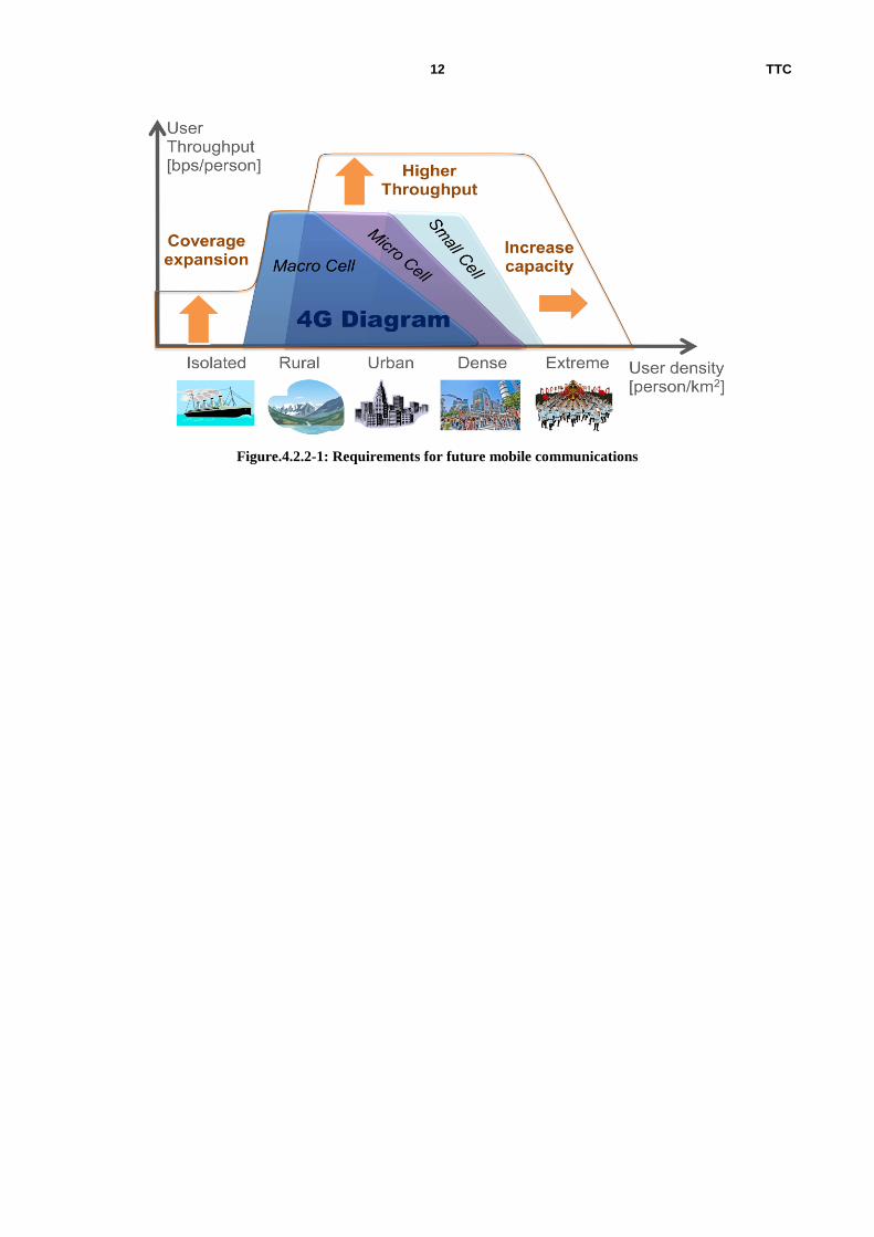
Figure.4.2.2-1 provides a VAN diagram outlining the requirements for future mobile communications. Compared with
4G, the future mobile communication requires larger capacity in the Extreme area, faster communication in areas such
as Rural, Urban, Dense, etc. and expanded coverage in the isolated area.
Especially regarding the capacity increase, applications like AR (Augmented Reality) and real-time cloud access are
assumed, with data rate requirements of 100 to 1000Mbps at any given time and around 10Gpbs at peak.
Small cell Macro cell
Up to 200m
Up to 2km
Logical path
TTC 12
Figure.4.2.2-1: Requirements for future mobile communications

TTC 13
4.2.3 Technical issues in the current network
4.2.3.1 Core network
The main factors of mobile traffic increase are expected to include the increase in new applications such as AR and real-
time cloud access as well as large amount of packets like video. At the same time, short-packet transmissions are also
expected to increase due to M2M/IoT. Various types of packets (log/short packets, burst) need to be transmitted. In
addition, traffic volume fluctuates greatly depending on the hour of day and sharply increases unexpectedly at a mass
event or during a disaster.
(*1) For the traffic from May 2011 to May 2014, a part of the traffic for communications with cellphone networks is excluded which was included in the
traffic up to Nov 2010.
Figure.4.2.3.1-1: Traffic change based on the hour of day for broadband service subscribers (comparison
over the past six years)
(Source: [4])
Not only the long-term traffic increase, but also diversified traffic types and a temporary increase cause the processing
load of the U-plane Core Network equipment to increase. As the processing load of the Core Network equipment
Upload
Mon Tue Wed Thu Fri Sat Sun
May
May
May
May
May
May
Download
Mon Tue Wed Thu Fri Sat Sun
May
May
May
May
May
May

TTC 14
increases, more time is needed to process U-plane packets, resulting in data packet latency or congestion (rejection) and
lower network reliability. On the other hand, adding core network equipment in anticipation of traffic growth would
lead to increased facility costs.
To cope with this issue, a mechanism for dynamically allocating network resources according to traffic is needed. More
specifically the followings need to be examined:
(1) Method for changing the radio access network, mobile network route or connection destination
according to traffic
(2) Method for changing mobile network functions and resource allocation according to traffic
In addition, along with the increase in the number of M2M/IoT terminals, the memory size that needs to be retained to
keep the connection in the idle state will become huge in the current EPC. In the future, it is possible to use a method
for not continuously connecting specific M2M/IoT terminals that support intermittent connection and require low
connection latency.
4.2.3.2 Mobile Backhaul
To aggregate a large number of fast lines, a transmission capacity of 100Gbps or greater is required even when the
statistical multiplexing effect is taken into account. For instance, if one Mobile Fronthaul (small cell) supports a peak
data rate of 10Gbps and 10,000 users with a usage rate of 0.01%, the capacity is 10Gbps. The number of small cells that
can be deployed in one macro cell is about 100. So when the capacity per small cell is 10Gbps, a capacity up to 1Tbps
needs to be considered for the Mobile Backhaul. Furthermore, as traffic increases, there is a concern about the increase
in the number of transponders even when wavelength multiplexing is applied. Therefore, configuration study is also
necessary in terms of high speed, large capacity and optical network.
At present, a technique for supporting 400Gbps with a single wave is being studied, but only up to 100Gbps has been
achieved on a production level. A transmission rate of 1Tbps will be provided by parallel transmission using
Wavelength Division Multiplexing (WDM). The configuration overview is provided in Figure.4.2.3.2-1. The WDM
transceiver consists of optical transceiver and wavelength MUX/DEMUX. The table in the figure shows the number of
required units to achieve 1Tbps with the existing transceiver.
Figure.4.2.3.2-1: Configuration of WDM transceiver to achieve 1Tbps
Only a single module cannot provide 1Tbps. Thus optical modules of 10Gbps/40Gbps/100Gbps have to be configured
using multiple channels, which will cause the cost to increase sharply. Although the price is getting moderate thanks to
the spread of 10Gbps/40Gbps optical transceivers, the price of 100Gbps optical transceiver is projected to soar even in
2010 based on the market trend. Therefore, although it is easy to configure with 100Gbps transceivers requiring less
number of channels and wavelength, we will wait and hope for price decline when the product is prevalent in the future.
The 40Gbps transceiver also requires a small number of channels, but the number of wavelength is the same as the
10Gbps transceiver. So either 10Gbps or 40Gbps will be selected depending on the equipment size, drive control
methods according to traffic volume, etc. It is hoped that a 40Gbps transceiver with a single wavelength will be
provided using high-speed electrical processing circuits.
BBU GW
TRx
TRx MU
X/D
EM
UX
WDM
トランシーバ
TRx
TRxMU
X/D
EM
UX
WDM
トランシーバ
1Tbps
単体 Ch数 波長数
10Gbps 100 100
40Gbps 25 100
100Gbps 10 40
Transceiver Transceiver
Single unit # of Ch # of wavelength

TTC 15
4.2.3.3 Mobile Fronthaul
Figure.4.2.3.3-1 shows the configuration of the Mobile Fronthaul. Due to high-speed data rate of mobile terminals
(great capacity at a cell), the capacity of the line used for the Mobile Fronthaul needs to be increased. For example, a
transmission capacity of about 160Gbps (about 16 times) 1is required to support 10Gbps terminals in the current CPRI-
based Mobile Fronthaul.
Figure.4.2.3.3-1: Configuration of Mobile Fronthaul
Furthermore, widespread deployment of small-size cells is expected to support high-speed and large-capacity mobile
communications. In addition to macro cells with a radius of several kilometers, small cells with a radius of some dozens
of hundreds of meters are being considered to be deployed together. For instance, assuming that a macro cell of 2km
radius is replaced with small cells of 200m radius, the number of cells calculated based on the superficial area would
increase 100 times. This brings up a concern about sharp increase of network cost due to increase in the number of links
in the P2P configuration used for the current fronthaul.
Figure.4.2.3.3-2 and Figure.4.2.3.3-3 provide the number of links in the macro/small cell. If a macro cell (2km radius)
is replaced with small cells (200m radius), the followings are expected.
The number of small cells increases 100 times.
Required fibbers and MFH optical transmission equipment also increase 100 times due to the increase
in the number of small cells.
The cost increase due to large capacity of MFH optical transmission equipment needs to be taken into
account.
Figure.4.2.3.3-2: Number of links at macro cell
1 Mobile fronthaul optical transmission capacity (20 MHz, 2x2 MIMO, CPRI transmission) when it is applied to
LTE (DL: 150 Mbps) can be calculated using the following formula. Namely, for the communication rate of a UE,
16 times larger capacity for MFH capacity will be required.
(Ref.: [5], 7.1.1)
Terminal data rate:
Max 150Mbps transmission
capacity
Fiber
Site building
MHF equipment: 1 unit Site building
Quantity of optical fiber: 1
transmission
capacity

TTC 16
Figure.4.2.3.3-3: Number of links at small cell
Summarizing the issues for the Mobile Fronthaul based on the above discussion, the major issues are the followings: (1)
Large-capacity transmission of 100Gbps or more and (2) Increase in the number of links.
(1) Regarding the large-capacity transmission of 100Gbps or more per cell, possible methods include reduction of
transmission data amount and improved efficiency with transmission data compression. In the current CPRI
transmission, however, radio signals in use cannot be identified at the optical layer, requiring all radio signals to be
sent. The bandwidth in use also cannot be identified at the optical layer. So the calculation is made using the peak
rate.
(2) Regarding the increase in the number of links, the number of fibers and equipment is expected to increase as long
as the current P2P configuration is used, causing the cost to increase. Thus the system change to P2MP may need to
be considered. A specific method for achieving this can be PON (TDM/WDM techniques, etc).
4.2.3.4 Common issues in the Mobile Backhaul/Fronthaul
Increase in the number of links at Mobile Backhaul/Fronthaul
The increase in the number of links due to small cell deployment (see 4.2.3.3) is also an issue in the Mobile Backhaul.
Therefore, there is a concern about network cost due to increase in the number of links in the P2P configuration in both
Mobile Backhaul and Fronthaul. The increase in the number of links also causes the number of equipment to increase,
leading to huge power consumption. Thus it is necessary to study architecture to build economic and low-power Mobile
Backhaul/Fronthaul.
4.2.3.5 Requirements for the future network
It is required to flexibly and economically support requirements such as a transmission capacity beyond 100Gbps,
diversified traffic patterns and 100 times increase in the number of cells.
4.3 Load increase in C-plane C-plane
4.3.1 Outline
According to [1], about 100 times more terminals (compared with 2012) need to be accommodated to support M2M/IoT
terminals in the future mobile network. The characteristics of the M2M/IoT terminals are different from the terminals
operated by people in that M2M/IoT communications concentrate during specific hours of the day. Handover
opportunities also increase as more small cells are deployed. Due to these factors, the C-Plane processing load for
connection/disconnection, handover and paging may increase shapely in specific areas or during specific hours of the
day in the Core Network. In addition, the architectures are expected to be diversified because M2M/IoT terminals to be
局舎
BBU
RRH
・・・
光ファイバ:100本
MHF装置数 100台
MFH伝送容量: 100Gbps以上端末通信速度:最大10Gbps以上
MHF equipment: 100 units
Site building
Terminal data rate:
Max 10Gbps or greater
Quantity of optical fiber: 100
transmission
capacity or more

TTC 17
accommodated are connected via the GW, etc. It is necessary to address a shortage of ID digits for terminal
identification due to increase in the number of terminals and redefine terminal identification.
4.3.2 Future scenarios
Not only mobile phones but also various devices are connected to a network. The IoT technology that provides an
environment for data exchange without human intervention as well as the M2M (Machine to Machine) communication
where devices connected to a network communicate each other are advancing.
Furthermore, grouping the M2M/IoT terminals by service, area or local network connection is considered to be
effective, and relevant studies are already being conducted at 3GPP. Fig.4.3.2-1 shows a case being examined at 3GPP.
Figure.4.3.2-1: Examined case at 3GPP (Excerpt from [6])
The M2M/IoT terminals are indicated as Local-Access Device in Figure.4.3.2-1. As described above, the number of
M2M/IoT terminals is expected to grow exponentially. In addition, considering diversified architectures that support
local networks accommodating each M2M/IoT terminal, it is possible that the MTC service provider will directly
manage each M2M/IoT terminal across multiple access lines. It is also necessary to thoroughly examine terminal
identification to comprehensively manage a huge number of M2M/IoT terminals. See 4.3.3.2 for more discussion about
terminal identification for mobile phones and M2M/IoT terminals.
4.3.3 Technical issues in the current network
4.3.3.1 Core Network
The M2M/IoT communications tend to concentrate at specific times of the day when small-sized data are intensively
sent out from numerous terminals, which is a characteristic different from conventional communications. Thus
concentrated control signals (C-Plane) cannot be processed with the conventional network resource
managing/controlling techniques assuming human behaviors (e.g., mobile phones) that perform random
communications to some extent, which may result in a network crash. Load is concentrated on equipment that processes
C-Plane intensively (e.g., MME), causing various possible problems such as network disconnection, large delay and
disruption of services like voice call. The mobile network control processes that are expected to increase greatly in the
future at C-Plane are as follows:

TTC 18
Figure.4.3.3.1-1: Load concentration at C-Plane
Connection/disconnection process
Load associated with the processes on the network required to connect/disconnect control connections and establish
bearers during terminal communications. The conditions for connection/disconnection processing on the network
include when a mobile terminal transitions from the Connected to Idle state as well as from Idle to Connected state. It is
also applicable when multiple grouped communication terminals are collectively connected/disconnected. Processing
load is concentrated in specific areas or at specific times of the day due to increase in the number of terminals
performing frequent communications like sensors. This raises an issue of C-Plane process load concentration at the
MME in the current system.
Handover process
Load associated with handover processes generated on the network when communication terminals move. The
conditions for handover processing on the network include when a mobile terminal moves from one base station to
another in Connected state. As small cells are deployed in the future, the handover frequency will increase, causing
handover processing to concentrate in specific areas or during specific hours, which results in concentrated C-Plane
processing load at core equipment like the MME and S-GW and the eNodeB
Paging process
In the mobile network, when new downlink traffic (incoming downlink data or voice) arrives for a communication
terminal in standby state, a paging signal is sent. In response to the paging signal addressed to the mobile terminal, the
terminal initiates a process to connect to the network to receive the traffic. This connection process involves
establishment of a control connection and bearer. When communications with various types of M2M/IoT terminals
increase in the future, the opportunities for a server at the center to send a PUSH notification is expected to increase,
causing PUSH processing to concentrate in specific areas or at specific times of the day. This creates an issue of high C-
Plance processing load at the MME and eNodeB. A technique such as smoothing PUSH notification timings according
to the network load will be needed.
UEs eNodeBs
MME
E-UTRAN EPC (Evolved Packet Core)
EPS (Evolved Packet System)
C-Plane
・・・
High load!

TTC 19
4.3.3.2 Terminal identifier (Identification)
The present mobile terminal is managed with an identification called IMSI associated with the SIM card. The structure
of the IMSI is provided in Figure.4.3.3.2-1 which is defined in the numbering plan in the ITU-T E.212. It is assumed
that each terminal belongs to a mobile operator identified by the MCC and MNC. The business model related to the
M2M/IoT terminal is expected to be greatly diversified in the future, so the current device approval with the IMSI may
become an obstruction in diversifying the business. In addition, according to the current 3GPP specification [7], the
IMSI shall not exceed 15 digits, which may be insufficient to accommodate a huge number of M2M/IoT terminals.
Therefore, it is necessary to study an efficient receiving technique that can identify a vast number of M2M/IoT
terminals.
MCC
Not more than 15 digits
3 digits 2 or 3
digits
MNC MSIN
NMSI
IMSI
Figure.4.3.3.2-1: IMSI structure (Excerpt from [7])
4.4 Transport layer
4.4.1 Outline
Future mobile networks will be in heterogeneous environment using various frequency bands. However, in
heterogeneous environment, due to insufficient support for end-to-end congestion control or multi-path communication,
the existing TCP/IP communication will not be able to handle sudden change of bandwidth and latency due to frequent
occurrence of handover. Also, it is expected that various applications will be created, hence applications with tolerance
against changes on the different network side will operate. Building networks that meet requirements of all such
applications is difficult in terms of technology and business, hence new transport layer appropriate for heterogeneous
environment will be required.
4.4.2 Future scnenario
Future mobile networks will be heterogeneous networks where interconnections are made by various radio access
technologies. Namely, the network configuration has overlayed small cells such as Pico cells (apx. 50 meters to apx.
500 meters of radius) and Femto cells (apx. 50 meters or less of radius) whose transmission power is low on Macro cell
coverage. (Figure.4.4.2-1). When users move in such a heterogeneous network, they will go through a small cell in a
short period. At that time, the quality (bandwidth/latency) of the accessed line will be changed discretely as they use
multiple frequencies at the same time or the speed is switched to higher one. For example, when a user enters into a
small cell, higher bandwidth is available than that of Macro cell area. However, since the cell coverage is small, the
bandwidth becomes unavailable when the user moves out of the small cell.

TTC 20
Figure.4.4.2-1 Heterogeneous network
4.4.3 Technical issues of the current network
The current congestion control argorithm which uses TCP/IP is a control based on the window size, where control is
repeated that basically widens the window size little by little and closes the window size in case contestion such as
packet loss occurs. Currently, to handle this, TCP congestion control technology for radio access network is proposed
and implemented, however, it is to solve the issue of high-latency/broadband line, but not to handle discrete quality
change as heterogeneous network. CUBIC, which is a standard in Linux OS as of 2015, is also TCP to support high-
latency/broadband line, however, it is not able to handle sudden change of quality.
To clarify the technical issue, an experiment to transfer a file between Linux PCs using iperf was performed. A wired
line was used for connecting the PCs and the bandwidth was limited to 100 Mbps using network emulator.
Figure.4.4.3-1 shows the result of increasing the transmission latency from 10 ms to 50 ms after five seconds after the
start of file transfer and the contrary case using network emulator. The vertical axis is average throughput per 100 ms.
Figure.4.4.3-1 Throughput change when latency was suddently changed
Also, Figure.4.4.3-2 shows grahps when latency was fixed to 10 ms and the bandwidth was changed from 100 Mbps to
500 Mbps under the same environment. From the results, it is known that when latency becomes low or bandwidth
becomes small, quality change is immediately followed though packet loss occurs. On the other hand, when latency
becomes high or bandwidth becomes large, it takes around five seconds to sufficiently use line quality. If walking speed
of a person is 1.4 m/s, a UE moves appx. 7 m. Therefore, if there is only appx. 50 m of coverage, the user may not be
able to use the line quality sufficiently but move out from the area.
マクロセル
スモールセル
ヘテロジーニアスネットワーク
0
20
40
60
80
100
0 5 10 15
スループット
[Mb
ps]
時間[秒]
0
20
40
60
80
100
0 5 10 15
スループット
[Mb
ps]
時間[秒]
(a)伝播遅延を10ms⇒50msに変更 (b) 伝播遅延を50ms⇒10msに変更
Macro cell
Small cell
Heterogeneous network
Time [second] Time [second]
Th
roug
hpu
t [M
bp
s]
Th
roug
hpu
t [M
bp
s]
(a) Propagation latency was changed from 10 ms to 50 ms (b) Propagation latency was changed from 50 ms to 10 ms

TTC 21
Figure.4.4.3-2 Throughput change when bandwidth was suddently changed
MPTCP is a technology that enables high-speed communication by simultaneous use of multiple interfaces and
seamless interface switching by using multiple paths. However, since there is overhead such as insertion of multiple
path routes or negotiation of new TCP/IP path, its capability may not be sufficiently used in a heterogeneous network.
Figure.4.4.3-3 shows average throughput when a file is downloaded by a terminal with Wi-Fi (802.11g) using iperf. At
this time, let us assume that the UE is connected to a line of 1Gbps only for “a” second every 30 seconds. Two
interfaces can be used seamlessly by MPTCP, however, if the connectin period “a” is less than 4 seconds, the line of 1
Gbps cannot be used. Namely, if the visiting period of small cell is less than 4 seconds, the user goes through the small
cell without using its bandwidth even if it uses MPTCP. This time, the IP address of each PC is set to static, and
considering negotiation at L2 and the allocated period of time for IP address in reality, MPTCP is not always applicable
to heterogeneous network.
Figure.4.4.3-3 Throuput when MPTCP is used in an environment where two networks mixedly exist
Moreover, even if broadband line is provided for wireless line, it may not be effective depending on applications.
Figure.4.4.3-4 shows the average throughput per second when YouTube is viewed using a dedicated application for
Android. This application uses TCP/IP, however, the rate is limited to 500 kbps by control on the application side
currently. Therefore, even when bandwidth higher than it is prepared, the application will not use it. Also, burst
reception between 0 to 7 seconds is buffering to absorb jitter, hence playing the video is started after the quality such as
line latency is measured first. Therefore, if line quality is changed in the middle, buffer overflow may occur, which may
cause problem in playing a video. Thus, in future mobile networks where various terminals and applications are
connected, there may be cases where providing lines of low latency and broadband for all the applications have no
effect. Namely, it is important to provid line quality according to applications, and setting of line quality coordinated
with applications will be important.
0
100
200
300
400
500
0 5 10 15
スループット
[Mb
ps]
時間[秒]
0
100
200
300
400
500
0 5 10 15
スループット
[Mb
ps]
時間[秒]
(a) 帯域を100Mbps⇒500Mbpsに変更 (b) 帯域を500Mbps⇒100Mbpsに変更
0
100
200
300
400
500
600
0 2 4 6 8 10 12 14
平均スループット
[Mb
ps]
接続時間 a [秒]
理論値
Time [second] Time [second]
Th
roug
hpu
t [M
bp
s]
Th
roug
hpu
t [M
bp
s]
(a) Bandwidth was changed from 100 Mbps to 500 Mbps
Av
rrag
e th
rough
pu
t [M
bps]
Connection period “a” [second]
(b) Bandwidth was changed from 500 Mbps to 100 Mbps
Theoretical value

TTC 22
Figure.4.4.3-4 Average throughput per second when YouTube is viewed on Android terminal
4.4.4 Requirements for the future network
Based on the above issues to be considered for transport layer in a heterogeneous environment are follows:
Control of transport layer that can follow frequent changes of line
Provision of line quality that meet the requirements of applications
The roles of them are the roles of transport layer that is positioned between applications and networks, hence
technologies that associate various terminals/applications and heterogeneous networks consisting of various access
networks will be required.
For a technology to solve the abovemenitoned issues, not only the existing TCP/IP but also use of ICN (data aware
networking technologies), which is getting attention in recent years, shall be considered also. One of the characteristics
of ICN is decoupling of sender and recipient, which enables communication not dpending on current end-to-end session.
Also, cross-layer technology with the technologies of lower layer than transport layer such as aggregation of multiple
frequency bands with L2 like CA and network virtualization such as SDN shall be studied.
4.5 Ultra low latency
4.5.1 Outline
In the future mobile network, provision of new services requiring real-time performance is necessary, and support for a
requirement of 1ms or less latency is being considered for E2E. Latency due to transmission distance is a physical
amount determined uniquely, so it is required to establish technologies such as (1) minimized routing path with
optimized layout for each transmission equipment, (2) reduction of processing latency for modulation/demodulation
processing time, protocol conversion processing time, etc. and (3) study of overall network architecture that
incorporates these technologies.
4.5.2 Future scenario
In the future mobile network, it is expected that new mobile services with very low latency will appear, which could not
be provided with 4G. Specifically, an E2E latency requirement of 1ms is being considered for such applications as
tactile communication, AR and auto-driving.
0
500
1000
1500
2000
2500
3000
1 2 3 4 5 6 7 8 9 10 11 12 13 14 15 16 17 18 19 20 21 22 23 24 25 26 27 28 29 30 31 32 33 34
スループット
[kb
ps]
時間[秒]
画像
画像
関連動画一覧
関連動画一覧
コメント
動画
Time [second]
Th
roug
hpu
t [M
bp
s]
Image
Image
Related video list
Related video lit
Comment
Video

TTC 23
4.5.3 Technical issues of the current network
4.5.3.1 Core network
In the future mobile network, very severe requirements for network have to be met. The key challenges to be addressed
are as follows:
(1) Physical latency due to distance
(2) Impact on network architecture
The latency due to distance depends on the medium (e.g., optical fiber), so further reduction needs to be considered
from a network architecture perspective.
In the current EPC Architecture, the communication path is configured with the P-GW as anchor point. In order to
support low latency communication, the anchor point needs to be put at a short distance from the communication
terminal. As shown in Figure 4.5.3.1-1, the Local GW is deployed near the terminal as an anchor point to support the
Home eNodeB in the LTE configuration. However, because the Local GW is fixed and cannot be relocated, the Local
GW gets far from the terminal as the terminal moves, causing increased latency, while support for both fast mobility
and low latency is required for services like V2V (Figure 4.5.3.1-1 is shown as an example. As UE1 moves from
eNodeB 3 to eNodeB 2 and to eNodeB 1, the latency increases).
Figure 4.5.3.1-1: Issue point of 4G Network (LTE)
4.5.3.2 Mobile Backhaul/Fronthaul
Figure.4.5.3.2-1 shows the basic mobile network configuration, showing where and how long latency occurs in the
RAN (Radio Access Network) in a detailed diagram. The upper part shows the conventional configuration without the
LTE
Cent ral IP Service
Mobile Access
Network
Local IP
Service
Internet / Int ranet
Applicat ions
L-GW
UE2
eNodeB
1
YouTubeIMS
UE1 UE1
P/S-GW
eNodeB
2
eNodeB
3
eNodeB
4

TTC 24
MFH. The lower part shows the configuration when the MFH is deployed. In this section, to provide generality, the
functions of radio TRx in the BS are divided in two, considering the connection between the one part (e.g., modulation
and demodulation unit (M/dMU) and the other part (e.g., RAU: radio antenna unit) as the MFH and the link for it as the
MFH link. Likewise, the connection between the BS and the MNN (Mobile Network Node) is considered as the MBH
and the link for it as the MBH link. Each RAT shall be applied for the radio link consisting of the radio TRx in the BS
and the MS (mobile station) and the radio propagation space between them. It is assumed that each link is generally
composed of TRx at both ends and transmission medium, with each TRx containing Lyer1 and Layer2 functions. There
are some candidates for the demarcation point separating the TRx function in the MFH. The appropriate demarcation
point to separate the TRx function may be selected according to requirements, etc. For example, industry’s standards [8]
and [9] specify the digital serial interface between the REC and the RE separated in the radio base station. The
separated and remotely placed functions (partial radio TRxs) both provide original functions as radio TRx, so these
functions and the MFH link can be considered the virtual radio TRx (practical TRx). For the same reason, both
separated partial BS functions and the MFH link can be considered the virtual BS (practical base station). Thus, the
MFH link can be translated as internal wiring for the radio TRx or base station.
According to Section 4.5 in [10] and Section 6.2.2 in [11], the user plane latency (tlatency_U-plane) is considered to
correspond to the link latency due to RAT (tlink_RAT) in Figure.4.5.3.2-1. This latency (tlink_RAT) consists of the processing
latency of the radio TRx in the BS (tTRx_BS), the propagation latency of the radio space (tmedium_radio) and the processing
latency of the radio TRx in the MS (tTRx_MS). If the MFH link is implemented, the processing latency of the radio TRx in
the BS (tTRx_BS) consists of the processing latency of functions in the radio TRx placed on the network side (tM/dMU_BS),
the latency of the MFH link (tlink_MFH) and the processing latency of functions in the radio TRx placed on the cell side
(tRAU_BS). Furthermore, the latency of the MFH link (tlink_MFH) consists of the processing latency of the MFH TRx placed
on the network side (tTRx_MFH), the propagation latency of the MFH link (tmedium_MFH) and the processing latency of
functions in the MFH TRx placed on the cell side (tTRx_MFH). In the current mobile network architecture, the core
equipment is managed at a remote site from the base station. Thus, there has been a debate over the necessity to also
take into account the processing latency of nodes other than TRx in the BS, the latency of the MBH link (tlink_MBH), etc.
for the RAN link. The latency of the MBH link (tlink_MBH) can be further divided into the processing latency of the MBH
Figure.4.5.3.2-1: Basic configuration and latency for mobile network

TTC 25
TRx placed in the MNN (tTRx_MBH), the propagation latency of the MBH link (tmedium_MBH) and the processing latency of
the MBH TRx placed in the BS (tTRx_MBH). Note that the definition for the user plane latency is a subject of future study
according to the note in Section 13.3 in [12].
For instance, if 1ms is required for E2E latency, the latency is equivalent to the transmission distance of 100km (round
trip) based on the optical effective distance conversion. The physical latency due to distance (tmedium_radio, tmedium_MFH,
tmedium_MBH) is generally physical amount determined in proportion to the propagation distance if the transmission
medium (refractive index) is determined. Unless the routing path of the transmission medium constituting the MFH and
MBH in the RAN is shortened or the transmission medium itself is improved or innovated, the latency cannot be
reduced. Therefore it is necessary to appropriately deploy and place the devices in the RAN. Therefore after deducting
the processing latency due to factors other than distance including the time necessary for flaming, multi-access, or
protocol conversion process (tTRx_MS, tRAU_BS, tM/dMU_BS, 2*tTRx_MFH, 2*tTRx_MBH) from the latency requirement for future
mobile network, the derived value shall be converted to an effective transmission distance allocated to the RAN. Then
the equipment in the RAN needs to be installed and placed, taking into account the installation conditions at the
applicable area (e.g., geological and land-right restrictions, nature or heritage conservation restrictions, landscape
restrictions, securing extra fiber length). For example, as processing latency due to non-distance factors, the processing
latency at the MS (tTRx_MS) and the BS (tRAU_BS + tM/dMU_BS) are assumed to be about 1.5 ms respectively according to
Annex B.2 in [13]. This assumption does not meet the requirement of 1ms latency described above for future mobile
applications, so some improvements need to be made. Based on the above, the issue is how processing latency due to
factors other than distance can be reduced to cover a wider area with one RAN system. On the contrary, if the
improvement of processing latency due to non-distance factors cannot be expected, the latency due to physical distance
has to be reduced. When the latency allocated to physical latency is reduced, the area each RAN can cover gets small,
requiring a large number of RAN systems to be deployed to secure the service area equivalent to (or greater than) the
conventional. In that case, it is necessary to consider a core network architecture that can efficiently connect the nodes
in the RAN.
4.6 Ultra energy (electric power) saving
4.6.1 Outline
In the future mobile network, there are concerns about increasing power consumption as a result of increased
transmission rate and the number of devices in the Mobile Backhaul and Fronthaul. In light of the growing importance
of energy issues such as global warming, development of new technologies is expected to achieve at least the level of
4G or a target of efficiency at one-tenth of the current rate. To do that, it is required to study technologies including
equipment with high energy efficiency, active system control according to traffic fluctuation and a new Mobile
Fronthaul transmission method in building a system or network.
4.6.2 Future scenario
In order to accommodate traffic expected to expand 1000 times, it is necessary to increase the number of network
devices including packet switch and base station equipment. Especially, it is expected that more and more small cells
and base stations using C-RAN configuration will be deployed with an aim to provide faster network with wider
bandwidth and area expansion, leading to a sharp increase of the number of devices that constitute the Mobile
Backhaul/Fronthaul. Thus, there is a concern about increased power consumption.
4.6.3 Technical issues of the current network
4.6.3.1 Mobile Backhaul
There are two major issues of power saving for the Mobile Backhaul.
As a result of faster data rates over radio and increased number of accommodations, the following issues exist between
high-level concentrator SW (GW) and BBU:
- Increase in power consumption for optical transmission equipment due to faster optical transceiver and electric
processing circuit

TTC 26
- Increase in wasted power consumption due to traffic differences by time of day as a result of expanded concentrator
capacity
Communication capacity required for Mobile Backhaul
See 4.2.3.2.
Power consumption of optical transmission equipment with ultrahigh capacity
<Power consumption of optical transceiver>
The current product level of optical transceiver is as shown in Table.4.6.3.1-1(Reference: [14], [15], [16], [17]). Each
type of transceiver listed in the table supports transmission distance of 40km.
Table.4.6.3.1-1: Optical transceiver types and power consumption
The power consumption of the optical transceiver part in the transmission equipment can be calculated as follows:
Power consumption = (Capacity to achieve) / (Transmission capacity of transceiver unit) * (Power consumption of
transceiver unit)
The calculation results are as shown in Figure.4.6.3.1-1. For instance, to achieve 1Tbps with less than 150W and about
100,000 macro cells and also provide redundant configuration, it would be 150W * 100,000 * 2 = 30MW.
For the Backhaul, there is a concern about increase in the number of transponders due to traffic expansion even in the
case where wavelength multiplexing is applied. Therefore, fast, high-capacity and optical network configurations also
need to be studied.
<Power consumption of electrical processing circuit (interface process)>
0
20
40
60
80
100
120
140
160
0 200 400 600 800 1000
消費電力
[W]
Capacity to achieve [Gbps]
10G
100G
Transmission rate Power consumption
Up to 1 Gbps 1000BASE - LH ≦ 1 W
Up to
10 Gbps 10GBASE - ER ≦ 1.5 W
Up to
100 Gbps
100GBASE - ER4 ≦ 9 W
Digital coherent
≦ 20 W (DSP only )
Standard
Power
consumption
[W]

TTC 27
In addition, the power consumption of interface processing part of the existing switch equipment is about 30W per 10G-
1 port. So the power consumption for the interface processing part to achieve 1Tbps is 3000W, which is 20 times
greater than optical transceiver. And the consumption for the entire network is 600MW. Therefore, integration of
electrical processing circuits (40G, 100G) is necessary to reduce the power consumption.
Wasted power consumption due to traffic fluctuations
Figure.4.6.3.1-2[18] shows fluctuations of mobile communication traffic by time of day. Actual traffic greatly varies
depending on the hour of day, with about 4 times difference between the max and minimum according to the current
statistics. Therefore, if operating at the max transmission rate all the time, power ends up being wastefully consumed.
By applying variable control (drive control on a channel basis) according to traffic capacity, power consumption can be
reduced. For instance, if a 40Gbps transceiver is configured, drive control is applied to 1ch to 25ch with a step of
40Gbps.
Figure.4.6.3.1-2: Fluctuations of mobile communication traffic by time of day
4.6.3.2 Mobile Fronthaul
Figure.4.6.3.2-1 shows the configuration of Mobile Fronthaul. The major power saving issues in the Mobile Fronthaul
are as follows:
- The connection between the BBU and RRH complies with the CPRI standard and always uses a fixed rate regardless
of actual traffic volume.
- Deployment of small cells (increase of the number of devices) increases the total power consumption.
- Faster optical transceivers, electrical processing circuits, etc. between the BBU and RRH due to higher data rate over
radio increases power consumption.
Source: Ministry of Internal Affairs and Communications, White paper on telecommunications for 2014
About 4 times
difference
Mon Tue Wed Thu Fri Sat Sun
(Time)

TTC 28
Figure.4.6.3.2-1: Mobile Fronthaul configuration and power saving issue
Power consumption due to fixed rate communication
As is the case in the Mobile Backhaul, mobile communication traffic fluctuations by time of day is also an issue in the
Mobile Fronthaul. Especially, traffic fluctuations between cells are greater, which is likely to become more remarkable
with small cell deployment. Therefore, the current standard and system design that use a fixed rate for communication
causes wasted power consumption during the hours with light traffic.
Increase in total power consumption due to increased devices
For the future mobile network, small cell deployment is being considered to cope with further increase in traffic. This
causes increased cells (i.e., increase in the number network devices that constitute a cell), which raises a concern about
increase in total power consumption. Then, the impact of small cell deployment on the total power consumption for the
Mobile Fronthaul has been estimated as follows.
Table.4.6.3.2-1 shows the estimate assumption. It was assumed that there are 100,000 macro cell sites with 6 sectors for
the current network. For the future network, it was assumed that in addition to the current macro cells small cells are
superimposed and there are 1 million 1-sector small cells. The equipment power consumption used for the estimate was
determined in reference to the [14] document. In addition, two types of small cell transmission rate (1Gbps and 10Gbps)
were examined. At that time, the power consumption of 10Gbps was calculated as 1.5 times of that of 1Gbps.
Table.4.6.3.2-1: Estimate conditions
The power consumption for the current network (Pcurrent) and the power consumption for the future mobile network
(Pfuture) are calculated as follows. Where, Ncell is the number of cells, Nsector is the number of sectors per cell, Pequip is
power consumption of equipment, and Nport is the number of ports on the equipment.
Current Future
Cell config MBH ( Macro cell ) MBH ( Macro cell ) + MFH ( Small cell )
# of cells 100,000 100,000 (Macro) + 1 million (Small)
# of sectors/cell 6 (Macro)
6 (Macro) 1 (Small)
Equipment power consumption Macro: 4.5 KW (6 port BDE + 6 port BRE)
Macro: 4.5 KW Small: 1.2 KW (6 port BDE), 0.1 KW (1 port LRE)
Transmission rate Macro: 1 Gbps Macro: 1 Gbps Small: 1 Gbps or 10 Gbps
1. Fixed rate comm
3. High speed
2. More devices

TTC 29
{
𝑃𝑐𝑢𝑟𝑟𝑒𝑛𝑡 = 𝑁𝑐𝑒𝑙𝑙(𝑚𝑎𝑐𝑟𝑜) ∗ 𝑁𝑠𝑒𝑐𝑡𝑜𝑟(𝑚𝑎𝑐𝑟𝑜) ∗ (
𝑃𝑒𝑞𝑢𝑖𝑝(𝐵𝐷𝐸)
𝑁𝑝𝑜𝑟𝑡(𝐵𝐷𝐸)+𝑃𝑒𝑞𝑢𝑖𝑝(𝐵𝑅𝐸)
𝑁𝑝𝑜𝑟𝑡(𝐵𝑅𝐸))
𝑃𝑓𝑢𝑡𝑢𝑟𝑒 = 𝑃𝑐𝑢𝑟𝑟𝑒𝑛𝑡 + 𝑁𝑐𝑒𝑙𝑙(𝑠𝑚𝑎𝑙𝑙) ∗ 𝑁𝑠𝑒𝑐𝑡𝑜𝑟(𝑠𝑚𝑎𝑙𝑙) ∗ (𝑃𝑒𝑞𝑢𝑖𝑝(𝐵𝐷𝐸)
𝑁𝑝𝑜𝑟𝑡(𝐵𝐷𝐸)+𝑃𝑒𝑞𝑢𝑖𝑝(𝐿𝑅𝐸)
𝑁𝑝𝑜𝑟𝑡(𝐿𝑅𝐸)) (∗ 1.5)
As a result of the calculation, the total power consumption for the Mobile Fronthaul is up to 900MW for the future
network, twice that of the current network that is 450MW. Note that the power-generating capacity at a nuclear power
station is about 500MW per plant.
Increase in power consumption of equipment due to higher data rate
The major factors for the power consumption for the Mobile Fronthaul include the optical transceiver part, the electrical
processing circuit part and RF amplifier. As a result of higher data rate over radio, these devices need to be faster,
which leads to increased power consumption.
The power consumption of optical transceiver is as shown in Table.4.6.3.1-1. For the optical transceiver, enough power
saving is implemented on the level up to 10Gbps and therefore the impact is small. However, on the level of 100Gbps,
power consumption increases sharply and the impact cannot be ignored considering the power consumption with small
cell deployment. It is required to consider the impact of higher data rate on power increase also for the electrical
processing circuit and RF amplifier. High frequency bands may be added in the future network, so the impact due to
added frequency bands also needs to be examined.
4.6.4 Requirements for the future network
It is crucial to save power to curb the increase in power consumption for the entire network. In order to achieve the one-
tenth efficiency, it is necessary to study technologies including equipment with high energy efficiency, active system
control according to traffic fluctuations and new Mobile Fronthaul transmission methods in building a system or
network.
For the Mobile Backhaul, the terminal speed will be 10Gbps, which requires a transmission capacity at least 100 times
greater than the current one even when the statistical multiplexing effect is taken into account. If optical transceivers
with 100Gbps-1Tbsp capability are implemented with the existing technologies, the power consumption will be 8 times
greater than the current. Therefore, it is necessary to develop devices that achieve low power consumption using such
techniques as integration. However, it is difficult to achieve the efficiency of one-tenth power reduction with just
integration. So drive control according to traffic volume is required for transmission equipment (optical transceiver,
interface circuit, etc).
For the Mobile Fronthaul, the power consumption is expected to double the current level due to small cell deployment.
Therefore, to achieve the one-tenth efficiency for the whole communication system, power saving at one-twentieth of
that of the current equipment is required. To do that, it is necessary to implement a configuration that can drastically
control power consumption according to actual traffic volume or the number of connected UEs (when they are at a low
level). In addition, the power consumption of optical transceiver soars when the transmission rate goes over 10Gbps. So
in the future mobile network where the transmission rate over radio is higher at 10Gbps, a new transmission method,
instead of CPRI, etc, is required to achieve the same level of reduction for the optical transmission rate as that of the
radio transmission rate.
4.7 Ultra large-scale disaster/congestion/failure resilience
4.7.1 Outline
In the future mobile network, increase in traffic to be accommodated and expansion of accommodated terminals
including IoT are expected and the importance as social infrastructure will be greater than ever. Therefore, the network
needs to be more robust than ever against congestion and fault in the event of disaster. The existing network can only
cope with congested traffic during disaster by temporarily managing network resources and therefore does not ensure
sufficient network resources necessary during an emergency. It is necessary to take fundamental actions for the future
network such as allowing for prompt enhancement.
TTC 30
4.7.2 Future scenario
Disaster resilience can be considered from congestion and failure resilience perspectives.
For congestion resilience, the traffic during the Great East Japan earthquake in 2011 was 50 to 60 times higher than
normal with regard to voice communication via cellar phones. Concentrated service requests from base stations that
cover a wide area causes resource shortage and congestion. Telecommunication carriers then implemented 80 to 95%
traffic control [19]. It was extremely difficult for users to establish a voice communication. According to a survey result,
people made a call about 12 times on average until they succeed and about 14 times on average until they give up in
disaster-stricken areas[20].
For failure resilience, with regard to unexpected communication process disruption due to damage of network functions,
the earthquake and tsunami caused collapse, flooding and washout of building facility, split and damage of undergrad
cables, duct lines, etc., damage of utility poles, damage of aerial cables and collapse and washout of mobile base
stations, which resulted in severe damage [19].
Although no specific numerical target levels are shared as a future scenario in terms of disaster resilience, the
government and users both demand further enhancement of telecommunication networks based on the lessons learned
from the Great East Japan earthquake described above.
4.7.3 Technical issues in the current network
4.7.3.1 Core network
The congestion issue is considered as follows:
Existing network
In the event of disaster (or public events like year-end and new-year events), mobile communication carriers generally
secure necessary resources to maintain network functions and provide important communications (priority call,
emergency call, etc.) by scarifying other less important communications. The network resource here is assumed to be
the RACH capacity and signal-processing capability of network nodes.
Specifically, considering the RACH capacity as well as the fact that network node processing capacity is also used to
reject signals, an “access control mechanism” has been mainly applied which prevents the terminal from originating
calls in the first place. This is initiated at the terminal by the base station adding necessary information to the broadcast
information for the terminal.
Various access control mechanisms have been examined according to a variety of use cases. They are divided into two
major types; Access mechanism on a terminal basis and access mechanism for each call type. For the existing
mechanisms, the former approach includes the mechanism that restricts all terminals in sequence and the mechanism
that restricts only MTC terminals. The latter approach includes the mechanism that restricts only voice calls, the
mechanism that restricts non-voice calls (i.e., only voice calls can be made) and the mechanism that only allows for
specific originating calls on an application basis (this assumes a use case that only allows for Disaster Message Board
and Disaster Voice Messaging Service)
Issue when continuing to rely on existing network functions in the future
The existing network functions only manage available network resources even during a large-scale disaster and cannot
provide a fundamental solution that increases resources to cope with processing congestion. Unless some new functions
are implemented in the future, user communications continue to be sacrificed.
If, however, network processing resources can be added during a large-scale disaster, more traffic can be connected. In
the proof test for virtualization technology assuming a large-scale disaster as part of the “Research and development of
dynamic control technology for mobile communication networks in times of large-scale disasters” [21] project
commissioned by the Ministry of Internal Affairs and Communications, it was confirmed that the call connectivity rate
improves from 1 in 20 times to 1 in 4 times by increasing the EPC resources 5 times within 30 minutes (Note: The test
was conducted with a configuration that does not consider the impact of repeated calls).
Furthermore, it is expected that repeated calls will be eliminated and congestion will be settled soon by adding
resources within a short time. Traffic begins to increase due to users’ safety confirmation about 5 minutes after disaster
strikes. So a swift enhancement of network processing resources is required to prevent repeated calls.

TTC 31
As described above, the future challenge is to swiftly increase network processing resources within about 5 minutes. To
achieve that, a procedure that further affects congestion nodes such as reattachment should be avoided.
The failure issue is considered as follow:
Existing network
Call state management and call processing are implemented in a single physical node in an inseparable way. Therefore,
if the node fails, all the associated calls are disconnected.
Issue when continuing to rely on existing network functions in the future
Call state management and call processing should be implemented in physically separate nodes. By specially improving
the failure resilience of the call state management node, the failure resilience of the network as a whole may be
improved.
4.7.3.2 Mobile Backhaul/Fronthaul
It is necessary to build a network with high reliability that can secure communication lines, flexibly and dynamically
responding to Backhaul node change and topology change in such events as base station outage.
4.7.4 Requirements for the future network
The system needs to smoothly reallocate resources as required among multiple nodes connected to WAN within 5-30
minutes without configuration change in neighboring nodes and user service disruption.
The system shall be able to perform call state management and call processing in different nodes.
4.8 Diversified types of terminal/traffic/operator
4.8.1 Outline
The future mobile network is expected to further permeate society than the conventional mobile network. Not only the
conventional terminals like feature phones and smartphones that assume usage by people, but also a number of
terminals assumed to be embedded in devices are expected to emerge, creating a variety of equipment. As a result, the
traffic pattern may also be different. The end point of communication will be machines instead of people, and the
number of terminals for M2M communication is expected to increase exponentially. Furthermore, the information
exchange in M2M is expected to have a traffic pattern that differs significantly from the server-client data exchange in
the conventional IP network. In addition, a variety of operators are expected to operate mobile networks. Thus, new
challenges for the network are generated by diversification of terminal requirements, traffic patterns and mobile
network operators.
4.8.2 Future scenario
For the traffic for conventional mobile terminals used by people, as high-definition terminals with a large screen and
filming function become common, more and more various video contents are used as a medium and the OTT service is
expanded, which increases video traffic. Furthermore, as M2M terminals get popular, the traffic of M2M terminals is
expected to increase sharply.
In general, a connection topology like sensor network is assumed for M2M terminals, with possible use cases such as
management, monitoring and remote control of production facilities, lifelines, building and housing, vending machines
and heavy equipment. The device mobility is relatively low and both the occurrence frequency and data volume of each
traffic tend to be small, but the number of terminal connections per unit area becomes very large. From 2020 and
onward, along with the advancement toward IoT and IoE incorporating M2M, the terminals and applications to be
accommodated will further diversify. It is also expected that there will be many new players in the mobile service
industry as MVNO.

TTC 32
4.8.3 Technical issues of the current network
4.8.3.1 Core network
Accommodation of terminals and traffic with various requirements
For M2M terminals, it is expected users operate devices for a long time without being conscious of battery charge and
replacement in the use cases like smart meter. There is a requirement of 10-year battery life with only built-in power
supply, operating the terminal in the sleep mode most of the time. PSM is adopted in 3GPP ([22], [23]), but such M2M
terminals cannot be called from the network. So the issue is to maintain long battery life while supporting mode change
so that the terminals can be called from the network when necessary (e.g. emergency events). Such M2M terminals are
assumed in use cases with low mobility. In such cases as IoT where a variety of things communicate each other, it is
expected that communication modules will be attached to wearable terminals, pets and distributed cargo and built into
wheeled vehicles. In addition to the M2M device requirement stated above, additional requirements including support
for high mobility need to be met, which requires optimization for each use case.
In order to efficiently accommodate numerous M2M terminals, it is considered to be necessary to implement policy
control, addressing, etc. on a group basis for M2M terminals, which are different from normal mobile terminals.
Relevant studies are being conducted at 3GPP [24].
Regarding the traffic pattern of M2M terminals, C-plane traffic is relatively higher than U-plane traffic. It is inefficient
to accommodate them in the existing core network that is designed to accommodate the normal mobile terminal traffic.
Furthermore, the usage fee operators can charge is very low for M2M terminals compared with normal mobile terminals
because their data capacity per traffic is small, which may put pressure on operators’ profit. Also, for the normal mobile
terminals, the traffic pattern may greatly change due to various video contents used as a medium and new
services/applications using tactile communication, AR, etc. Thus, there should be another network configuration that is
fundamentally different in terms of design concept, which then raises an issue of huge capital investment.
Flexibility improvement for NW function release
Along with diversification of applications including M2M/IoT, the number of MVNOs is expected to increase to further
improve the convenience of users. The network has to be flexible to release sufficient resources for necessary core
network functions to MVNOs. In meeting a number of release requirements, there will be a various function
requirements for each MVNO, which requires scalability to meet new requirements.
4.8.4 Requirements for the future network
While high-volume traffic like video is increasing, we need to cope with M2M/IoT traffic and MVNOs increase. It is
necessary to provide required functions according to the characteristic of terminal/traffic/operator as well as a network
virtualization platform where network resources can be logically configured. The LINP (Logically Isolated Network
Partitions) concept to virtualize network resources and logically configure a virtual network according to various
services is defined in an ITU-T recommendation [25], providing a valid framework to resolve each issue described
above.

TTC 33
Figure.4.8.4-1: Conceptual architecture for network virtualization
(Source: [25])
4.9 Interworking with other RATs
4.9.1 Outline
Since radio frequency resources are limited and MNOs will have to bear more costs due to an increase in the number of
cells per unit area, it is foreseen that the future mobile network will become a multi-RAT environment where the
existing RAT cells and wireless LAN networks will be integrated and used. Accordingly, in addition to the integration
and management of various RATs for higher efficiency, the heterogeneous network of RATs with various
characteristics will need to assist in optimal cell selection for better quality of user experience in the network.
Additionally, since all RATs may not be accommodated in a single network, communication interworking through the
internet will be another important issue.
4.9.2 Future scenario
In order to accommodate 1,000 times more volume of traffic than the present, the frequency usage efficiency
(bps/Hz/cell), frequency bandwidth (Hz) and number of cells per unit area (cell/km2) will need to be decupled. As of
the year 2014, approx. 610MHz of frequency bandwidth is allocated to mobile networks and others and approx.
350MHz is allocated to wireless LAN networks, which is 960MHz allocation in total. According to [26], the Ministry of
Internal Affairs and Communications has stated that they will aim in the 2020’s to allocate 2700MHz of frequency

TTC 34
bandwidth to wireless LAN networks and others out of 2900MHz to be used for mobile communications in 6 GHz and
lower frequency bands (see Figure. 4.9.2-1). Accordingly, frequencies available to wireless LAN and others can be
expected to be nearly tripled. If more frequency bandwidth is needed, 6 GHz and higher frequency bands will be
expected to be used. Therefore, the frequency bandwidth allocated to a single RAT will not be enough to secure the
bandwidth required for the future mobile networks. The bandwidth for wireless LAN will need to be used together with
new RATs available in 6GHz and higher frequency bands in an integrated manner.
Figure.4.9.2-1 Frequency allocation status and plans in Japan
(Reference: [26])
Regarding the number of cells per unit area, mobile operators will have cost issues because an increase in the number of
cells due to Small Cell will cause an increase in the CAPEX/OPEX related to MBH/MFH and BTS. Since it is not
realistic in terms of cost to update all existing cells for the future mobile networks, a heterogeneous network will need
to be built in parallel with the utilization of the existing RATs (e.g. LTE) and wireless LAN cells. This will need multi-
RAT interworking.
4.9.3 Technical issues in the current network
4.9.3.1 Core networks
Even at present, data offloading to wireless LAN is actively encouraged in urban and other areas with tight traffic. In
those areas, optimal RAT selection and RAT interworking (e.g. seamless connection between wireless LAN and
mobile) are already offered. As shown in Figure.4.9.3.1-1, the details of interworking between wireless LAN and
mobile vary depending on the layer, from tight interworking between the networks to loose interworking with a weak
impact on the networks. Various interworking technologies standardized in 3GPP and others have been practically
applied.
As shown in Table.4.9.3.1-1, there are two main types of cells to be targeted for multi-RAT interworking: cells in
cellular technology and cells in IEEE 802.11 wireless LAN technology. Depending on the development of each
technology and expansion of frequency band, the types of cells to be interworked in the future mobile network will be
increased. In addition to the RAT mentioned here, sensor network system RAT may be integrated in the future in order
to accommodate IoT terminals for example. Basically, the existing interworking technologies will be applicable to the
future mobile networks, however, in Multi-RAT environment in the future mobile networks, the diversity of the
attributes of the cells to be interworked will be increased than current ones, which is a characteristic change. Since cells
with high frequency band such as millimeter wave will be used, cells that are smaller/narrower and faster than the
current ones will be integrated in the heterogeneous networks. Also, the operator of each RAT is not always a single
one, hence the quality of backhaul lines and provided services may be different depending on the cells. Moreover, in the
future mobile networks, new requirements such as ultra-low latency will be defined, however, it may not be realized in
all the cells, hence cells that meet the requirements and that cannot meet the requirements may be mixed. Due to the
abovementioned increase in the diversity of RATs, new functions will be required for the network architecture.
Specifically, provision of integrated management function of Multi-RAT and support function of optimal RAT selection
are considered, for examples.
What has been described above is mainly about RAT interworking in a mobile network. However, there will be more
requests about communications outside the mobile network, that is, with terminals/servers connected to the internet, too.
In order to improve the quality, that is, reduce the communication latency and increase the communication capacity
while tracking the mobility of terminals/servers, e.g. seamless move, is ensured, communication interworking
Original target: 2000MHz frequency bandwidth
[Current status] [2020]
1.7GHz band/2.3GHz
band/2.6GHz band/3.5GHz band/4GHz band/4.5 GHz band
5.3GHz band/5.4GHz
band/5.8GHz band
Mobile comm.: approx. 610MHz width [700MHz band/800MHz band/900MHz band/ 1.5GHz
band/1.7 GHz band/2GHz band/2.5GHz band]
* Indoor-only frequencies are excluded.
Wireless LAN: approx. 350MHz width* [2.4GHz band/5.6GHz band]
Secure appox. 2700MHz out of approx.
2900MHz that is the target
frequency bandwidth in total
e.g. Share frequencies with
existing mobile comm systems
6GHz and lower
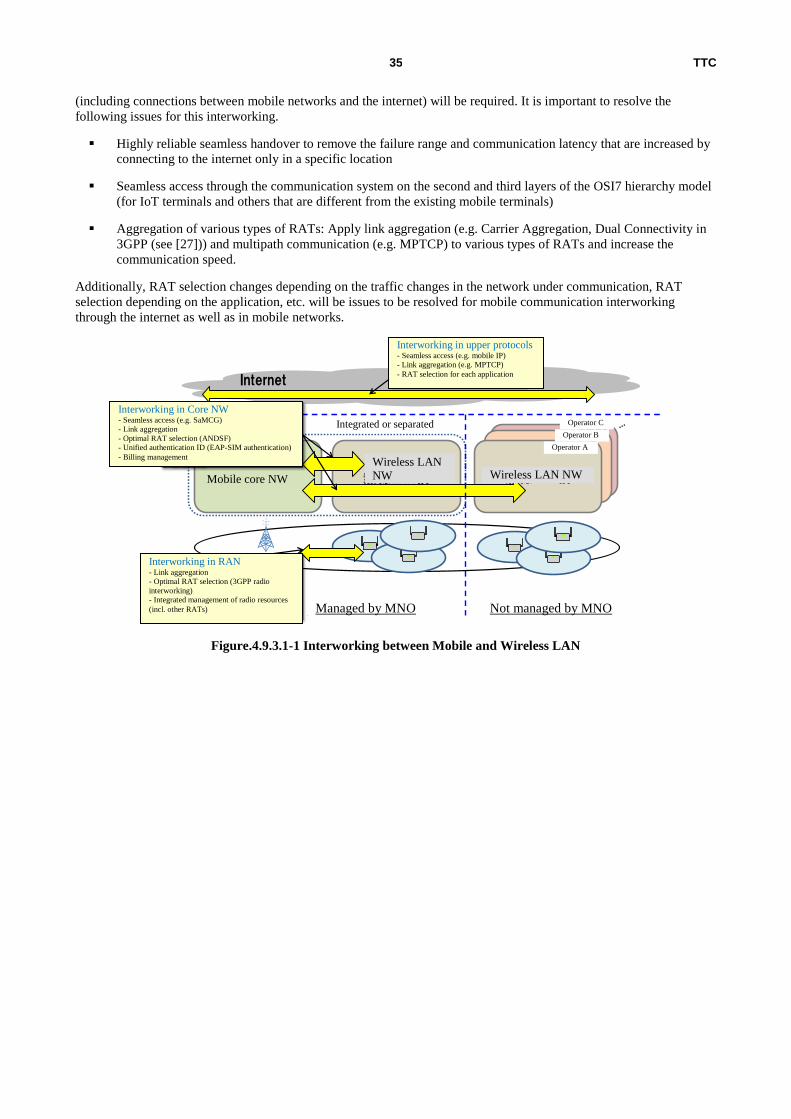
TTC 35
(including connections between mobile networks and the internet) will be required. It is important to resolve the
following issues for this interworking.
Highly reliable seamless handover to remove the failure range and communication latency that are increased by
connecting to the internet only in a specific location
Seamless access through the communication system on the second and third layers of the OSI7 hierarchy model
(for IoT terminals and others that are different from the existing mobile terminals)
Aggregation of various types of RATs: Apply link aggregation (e.g. Carrier Aggregation, Dual Connectivity in
3GPP (see [27])) and multipath communication (e.g. MPTCP) to various types of RATs and increase the
communication speed.
Additionally, RAT selection changes depending on the traffic changes in the network under communication, RAT
selection depending on the application, etc. will be issues to be resolved for mobile communication interworking
through the internet as well as in mobile networks.
Figure.4.9.3.1-1 Interworking between Mobile and Wireless LAN
モバイルコア網 無線LAN網無線LAN網
MNO管理 MNO管理外
コアNW連携・シームレスアクセス(SaMOG等)・リンクアグリゲーション・最適RAT選択(ANDSF)・認証ID統一(EAP-SIM認証)・課金管理
上位プロトコルでの連携・シームレスアクセス(mobile IP等)・リンクアグリゲーション(MPTCP等)・アプリケーションに応じたRAT選択
RAN連携・リンクアグリゲーション・最適RAT選択(3GPP radio interworking)・他RATを含めた無線リソース統合管理
Internet
事業者A
事業者B事業者C統合もしくは分離
Interworking in upper protocols - Seamless access (e.g. mobile IP)
- Link aggregation (e.g. MPTCP)
- RAT selection for each application
Interworking in Core NW - Seamless access (e.g. SaMCG)
- Link aggregation
- Optimal RAT selection (ANDSF)
- Unified authentication ID (EAP-SIM authentication)
- Billing management
Interworking in RAN - Link aggregation
- Optimal RAT selection (3GPP radio
interworking)
- Integrated management of radio resources
(incl. other RATs) Managed by MNO Not managed by MNO
Integrated or separated
Operator A
Operator B
Operator C
Wireless LAN NW Wireless LAN
NW Mobile core NW

TTC 36
Table.4.9.3.1-1 Main targets for multi-RAT interworking
Category RAT Frequency band Cell radius Rate
Cellular Licensed
band
LTE/LTE-A < 3GHz Dozens of meters -
dozens of kilometers
< 3Gbps
3.5GHz Dozens of meters – several hundred meters
5G < 6GHz, T.B.D. Up to 10Gbps
> 6GHz (e.g. millimeter
waves)
T.B.D.
Unlicensed
band
LTE-U(LAA) Possibly 5GHz band Approx. dozens of
meters – 100 meters
T.B.D.
Wireless LAN IEEE 802.11
a/b/g/n/ac
(Wi-Fi)
2.4GHz, 5GHz, Approx. dozens of meters – 100 meters
A few Mbps - 6.9 Gbps
IEEE 802.11ad
(WiGig)
60GHz Approx. 10m A few Mbps - 6.9
Gbps
IEEE 802.11ax 2.4GHz, 5GHz T.B.D. T.B.D.
IEEE 802.11ah <1GHz T.B.D. T.B.D.
4.9.4 Requirements for the future network
4.9.4.1 Integrated management of the Multi-RAT
Mobile operators will need to manage various RATs of cells. In order to efficiently manage those cells and make full
use of resources, a function will need to be provided to manage multiple RATs in an integrated manner. There are two
main types of integrated management: (a) Inter-RAT interface conversion and (b) Inter-RAT cooperative
transmission/load balancing (see Figure. 4.9.4.1-1).
(a) Inter-RAT interface conversion: It is preferred in terms of simplified core network facility management to be able to
accommodate not only the 5G RAT but also the existing RATs (e.g. IMT-2000) and other RATs (e.g. wireless LAN) in
an integrated interface to the mobile core network. Additionally, this interface is expected to have flexible scalability for
new RATs to be provided in the future.
(b) Inter-RAT cooperative transmission/load balancing: Inter-RAT cooperative transmission (e.g. improvement of
wireless LANs’ mutual interference by control on the mobile side), MAC layer-level inter-RAT cooperative scheduling,
etc. in the overlapping coverage and load balancing among RATs can be considered to secure more accommodation
capacity than when RATs are individually deployed. Architecture with consideration of BTS-to-BTS connections will
be required, depending on how the cooperation should be.
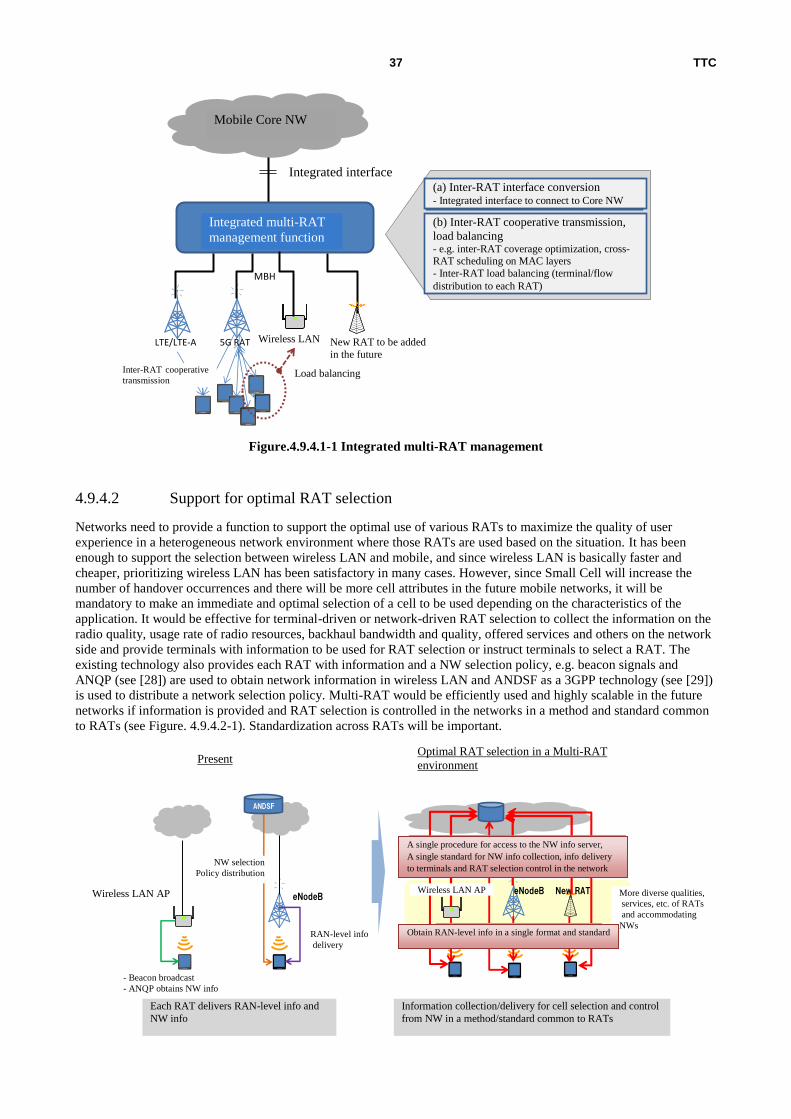
TTC 37
Figure.4.9.4.1-1 Integrated multi-RAT management
4.9.4.2 Support for optimal RAT selection
Networks need to provide a function to support the optimal use of various RATs to maximize the quality of user
experience in a heterogeneous network environment where those RATs are used based on the situation. It has been
enough to support the selection between wireless LAN and mobile, and since wireless LAN is basically faster and
cheaper, prioritizing wireless LAN has been satisfactory in many cases. However, since Small Cell will increase the
number of handover occurrences and there will be more cell attributes in the future mobile networks, it will be
mandatory to make an immediate and optimal selection of a cell to be used depending on the characteristics of the
application. It would be effective for terminal-driven or network-driven RAT selection to collect the information on the
radio quality, usage rate of radio resources, backhaul bandwidth and quality, offered services and others on the network
side and provide terminals with information to be used for RAT selection or instruct terminals to select a RAT. The
existing technology also provides each RAT with information and a NW selection policy, e.g. beacon signals and
ANQP (see [28]) are used to obtain network information in wireless LAN and ANDSF as a 3GPP technology (see [29])
is used to distribute a network selection policy. Multi-RAT would be efficiently used and highly scalable in the future
networks if information is provided and RAT selection is controlled in the networks in a method and standard common
to RATs (see Figure. 4.9.4.2-1). Standardization across RATs will be important.
Mobile Core NW
LTE/LTE-A 無線LAN
Multi-RATの統合管理機能
将来の新規RAT
統一インタフェース
(a)RAT間インタフェース変換・コアNWへの接続のインタフェースの統一
(b)RAT間協調伝送、負荷分散・RAT間でのカバレッジの最適化、 MACレイヤでのCross-RAT Scheduling等
・RAT間の負荷分散(各RATへの端末/フローの分配)
負荷分散RAT間協調伝送
5G RAT
MBH
ANDSF
eNodeB無線LAN AP
NW選択Policy配布
RANレベルの情報通知
・Beaconによる報知・ANQPによるNW情報取得
現状 Multi-RAT環境での最適RAT選択
RAT毎にそれぞれRANレベル情報、NW情報を配信
RAT間での統一的な手順・基準による、セル選択のための情報収集・配信およびネットワークからの制御
eNodeB無線LAN AP New RAT
統一的なフォーマット・基準でのRANレベル情報の取得
RAT、収容NWの品質・サービス等の多様化
統一的な手順よるNW情報サーバへのアクセス、統一的な基準に基づくNW情報収集、端末への情報配信、およびネットワークからのRAT選択制御
Mobile Core NW
Integrated interface
Integrated multi-RAT
management function
New RAT to be added
in the future
Load balancing Inter-RAT cooperative
transmission
(a) Inter-RAT interface conversion - Integrated interface to connect to Core NW
(b) Inter-RAT cooperative transmission,
load balancing - e.g. inter-RAT coverage optimization, cross-RAT scheduling on MAC layers
- Inter-RAT load balancing (terminal/flow
distribution to each RAT)
Wireless LAN
Wireless LAN AP
NW selection
Policy distribution
Wireless LAN AP
- Beacon broadcast
- ANQP obtains NW info
RAN-level info
delivery
Each RAT delivers RAN-level info and
NW info
Present Optimal RAT selection in a Multi-RAT
environment
A single procedure for access to the NW info server,
A single standard for NW info collection, info delivery
to terminals and RAT selection control in the network
More diverse qualities,
services, etc. of RATs
and accommodating
NWs Obtain RAN-level info in a single format and standard
Information collection/delivery for cell selection and control
from NW in a method/standard common to RATs
TTC 38
Figure.4.9.4.2-1 Support for selection among multiple RATs
4.9.4.3 Communication interworking through the internet
In this section, requirements for communication interworking between RATs of mobile network and the internet
regarding Highly reliable seamless handover and Aggregation of various types of RATs in order to improve the quality
in terms of lower communication latency and increase of communication capacity for applications while seamless
mobility on the networks including the internet is ensured.
- Highly reliable seamless handover: It will resolve the issue of resistance against failures and eliminate the issue of
increase in communication latency that may occur because access points with the internet are limited to specific
locations. As for the move to the other RAT within a mobile network of a terminal, seamless communication is
possible thanks to the interworking between LMA on the network side and MAG on the RAT side. However, for a
connection with the internet, if any failure occurs at LMA where the terminal is connected in the upper stream or at a
location close to such a LMA, the connection already established with the internet will be lost. Also, if a terminal
moves to a RAT that belongs to a different LMA or if the user on the other end of the communication moves to a
network away from the relevant LMA, latency will be increased. Seamless handover function by interworking among
networks and multiple RATs including some changes to LMA that will solve these issues will be required.
- Aggregation of various types of RATs: In addition to interworking within a mobile network such as link aggregation
and multiple-path communications using Multi-RAT, improvement in communication quality using multiple paths
including the internet lines will be required. Similarly to the abovementioned notification of quality on the backhaul
side from the network, mechanism such as notification of quality of the internet access point from the network side
and notification of quality from the terminal side can be considered.
4.10 Security
4.10.1 Outline
Security will be positioned in more importantly in the future networks. For building a network, the way of thinking
“security by design,” which considers security from the stage of design, will be important. As a point greatly different
from the networks so far, virtualization of networks and computer resources shall be considered. Though some of the
security issues are expected to be resolved by such virtualization, new security issues may occur. In this section, future
scenario and issues regarding security are suggested.
4.10.2 Future scenario
In the future, mobile networks will be a part of important social platform more than now, and life of people will greatly
depend on them. As the degree of dependency on such a platform is increased, cyber attack against the platform will be
more complex and sophisticated. Also, to aim higher availability, efficiency, and flexibility of networks and computer
resources, network/hardware virtualization technologies such as SDN and network function virtualization technologies
such as NFV will be prerequisites for mobile networks. For introducing SDN/NFV, following security issues shall be
considered.
4.10.3 Technical issues of the current network
4.10.3.1 Security issues regarding network/hardware virtualization
For network/hardware virtualization technologies, flexible management of networks and computer resources can be
realized by newly introducing control layer since handling networks and computers abstractly is possible. By this, it is
expected that security issues so far will be resolved, however, it is necessary to consider new threats also at the same
time. Namely, as far as the newly introduced control layer works normally, it will contribute to security enhancement,
however, in case the control layer is captured by an attacker, it may lead to a ruinous damage. Therefore, it is important
to ensure the security of SDN controller, orchestrator in NFV, and hypervisor or VMM for a virtual machine.

TTC 39
4.10.3.2 Security issues under the environment of the multi-tenant operator administrator
An NFV environment needs general-purpose NFVI providers that are assumed to be a combination of IaaS, NaaS and
PaaS providers. One example is an MVNO that rents an NMO’s infrastructure to offer services. MVNO will develop its
service form where it only provides networks to various combinations such as interworking with the upper-level
services. Under such an environment, the assumption will be greatly different from that of the current networks where
services have been provided upon vertically integrating the network infrastructure services. This means that in many
cases, network operators/administrators will not be the same as service operators/administrators because network and
services will be separately provided. When there are two or more administrators, mutual authentication and delegation
of authority need to be smooth and safe among administrators.
4.10.3.3 Security issues due to complex architecture
It would be difficult for operating personnel to create a drawing of and visually check physical and logical
configurations in a network hardware virtualized environment because they do not correspond to each other on a one-
on-one basis. To resolve the situation, computer-aided operation, automated network configuration of machines,
automated configuration verification of services and other technologies would be introduced. This issue could be more
complicated if it is in a multi-operator/administrator environment. For example, a configuration could not be made as
per expectations or it could be vulnerable to cyber attacks from malicious tenants.
4.10.4 For resolving the issues
To resolve such issues, technologies will be required to ensure security overall upon linking the security management of
the account machine system, which has been performed so far. First, in order to ensure the security of computer
resources, it will be necessary to be based on Secure Boot with tamper-resistant devices as a starting point of reliability.
Then, using the security status as the next original point, hypervisor shall be booted securely and the chain of reliability
shall be connected to VNF. Also, since it may be attacked after the activation, a technology to verify the safety
periodically (attestation) will be required. To ensure the security chain using attestation, not only verification from
inside the host but also remote attestation will be mandatory. Moreover, chains will be required such as ensuring
security as orchestrator by security interworking among multiple hypervisors and ensuring security by interworking of
multiple orchestrators. There are security issues as follows specifically:
Chain of trust/relationship building technologies and their underlying Secure Boot and remote attestation
Define trusted domains with the same policy attached
Share information and build a trusting relationship between trusted domains
4.11 Network operations
4.11.1 Outline
Accompanying the advance of high speed, high capacity, and low latency of mobile networks, great innovation and new
solutions will be required also for the network operations.
In the mobile communications, shift from feature phones to smart phones with high functions and high performance is
progressing, and the hurdle of development of application on them has been lowered, hence the number of applications
in the market is increasing. Also, expansion of MVNO business and increase in IoT and M2M communications are
expected, hence as a result of them, various new functions and new services are featured rapidly, which leads to fiercer
competitions of communication service provision. From now on, accompanying the advance and higher speed of radio
technologies, higher functions and higher performance of terminals are expected, therefore how rapidly such new
functions and new services can be provided is a key.
Since high reliability as a social infrastructure as well as high network performance will be expected, it will be
mandatory to make efforts for e.g. no service downtime. It will also be important to offer a future mobile network
service with high performance and reliability at a low cost.

TTC 40
4.11.2 Future scenario of the network management
Virtualization is getting attention in terms of networks, as one of promising technologies to build future mobile
networks. Virtualized network functions will be logically and dynamically configured and activated as applications on a
server. Applications and infrastructure need to support the following and others:
Componentized/virtualized functions, and a combination of those functions
Standardized technologies, utilization of open-standard technologies
Simplified/automated deployment
Operational work saved by integrated management
Figure.4.11.2-1 Image of a virtualized network
Introducing this network virtualization technology can be expected to produce the following effects:
Physical construction workload as an overhead in terms of schedule can be reduced or removed.
A testing period can be shortened because it is easier to minimize the difference between development and
commercial environments
Agile development, e.g. consecutive function addition/troubleshooting, can be expected to shorten periods.
Resources can be dynamically and logically added, depending on how widely new services are used.
If a new service is not popular, its resources can be reused for other services by making it smaller or
discontinuing it.
The above effects are expected to contribute to the creation of an environment to help with the more prompt provision
of new functions/services.
At the same time, it is expected that network virtualization will be effective for cost reduction in terms of software-
enabled network functions and universal use of hardware. Also, from software-enabled network functions, automation
of network operations is expected, which will be effective to reduce OPEX and to avoid human errors.
Based on the above, as for the operations of future mobile networks, issues regarding agility, no downtime, realization
of new functions, cost, and automated, flexible and simple operations are assumed.
Applications
Virtual infrastructure
Application Application Application
Virtual server
Virtual NW
Virtual storage
Inte
gra
ted
man
agem
ent

TTC 41
4.11.3 Issues about agility
Ensuring agility of new function/service offering
In general, when a new function or service is launched, an application is developed so that it can work on UEs (however,
application development is not required for some functions/services) and equipment required for the function/service
offering is procured and physical construction work is performed for the network. However, also for the applications to
offer a new function/service on the network side, specific environment (infrastructures including hardware and
networks) was required to run the applications in many cases, hence dependency between such applications and
infrastructure was high, therefore it was difficult to independently arrange an infrastructure, which required substantial
construction period, in advance. Such construction period has been blocking prompt offering of new functions and new
service. Network virtualization is recently a focus of attention as a technology to enable the building of common and
general-purpose infrastructure leading to a reduction in the construction period. As mentioned in other chapters of this
white paper, this technology is under consideration in various standardization bodies.
No service downtime
Basically, having a redundant configuration cannot be avoided as a measure against HW failures.
When there is a HW failure in a redundant system, only its backup system is operational. Therefore, it is needed to
ensure the reliability of the backup system.
A network in a virtual environment will need N distribution in the LB configuration or a scenario to automatically add
new SBY when there is a failure in ACT.
This function is under study as an auto-healing function in NFV. Improvement/application of this function will need to
be studied in the future.
Regarding the recovery form a failure (especially a failure due to e.g. attached burst), the current durability against burst
depends on the lowest performance node of MME, S/P-GW, AAA, Diameter and other related nodes. Due to this, it
takes time to make connections at a time after the failure. Flexible and dynamic CPU resource allocation with
virtualization is expected to improve the recovery capability by several percent to tens of percent.
This function is under study as an auto-scaling function in NFV. Improvement/application of auto-scaling, resource
equalization/replacement, etc. with this function will need to be studied in the future.
In addition, it is important to improve the quality of alarms that help to immediately identify a failure spot. It is
important for core NW management to make a recovery in a shorter time and ensure the reliability after immediately
identifying a failure spot.
Offering a new function e.g. with virtualization
File updates to introduce a new function to a network usually do not have an impact on commercial services (e.g. by
updating several nodes per night). It is expected to automate in-service file updates, by using the NFV file update
function in a virtual environment to dynamically transfer traffic from one node to another in a short time for day and
night file updates. It is needed in the network to implement the NFV auto-test function and reduce the time taken to
check the normality of file updates.
CORBA and other protocols as an interface to OAM cause high inter-system dependency. It is cost-consuming to
implement them and they disturb the implementation of standardized OAM. It will be needed to consider the use of the
industry-standard REST-IF protocol that is used in OpenStack and others.
International standardization activities that are currently ongoing at 3GPP:
1. NFV as a study item: A technical report on it is under preparation and it is studied together with ETSI NFV,
TMF and OPNFV. (The architecture, use cases and procedure of each use case are the main topics.)
2. Other than NFV:

TTC 42
1) Work item to reduce the workload on maintenance personnel by optimizing the alarm definitions as alarm
quality improvements
2) Study item to simplify the rules by re-extracting requirements from the current OAM specification as
Application and Partitioning of Itf-N
4.11.4 Issues of cost
The existing centralized architecture for operational management can be considered as the main factor to increase the
network management cost.
As shown in Figure.4.11.4-1, the existing operational management system is generally centralized to remotely manage
the FACPS of various facilities. Since most of original information is maintained in the facilities, the operational
management system collects the information through regular polling or event notification from the facilities.
Figure.4.11.4-1 Existing centralized network management
Reduction in CAPEX for network management
・ It is foreseen that it will be getting more difficult to maintain/improve the quality in the existing operational
method, because the volume of operational management information has been getting larger due to more
complicated and diverse network facility types and functions whereas the quality expected in network services
has been getting higher. Since the operational management system may be drastically changed or expanded to
maintain the quality of network services, there is a concern about an increase in the costs for the operational
system.
・ Factors for the CAPEX increase
More data to be monitored/managed (larger size of the related database and operational management
system)
Larger and more complicated system due to a part of response to the following factors for the OPEX
increase
Reduction in OPEX for network management
・ It is assumed that the efforts will be made with a combination of an operational management system and a
network configuration to enable flexible system modifications leading to a reduction (5GPPP’s target: 20% or
more) in the network operation cost in the management framework enabling prompt software deployment after
HW addition/replacement.
・ Factors for the OPEX increase
More workload for failure recovery support and more difficult verification in a testing environment, with
more complicated network functions
Operational
management system
Facilities,
Networks
(MFH/MBH/Core)
TTC 43
Decreased reliability (increased failure rate) with more general-purpose facilities
More frequent requests for configuration modifications (MVNO, XaaS)
Support for various types of data (M2M, IoT, Flash Crowd, Content (4K, 8K), Latency Sensitive)
Studying a new operational management architecture to help with a reduction of (cost) restrictions attached to the
existing architecture, and to be more specific, the following three can be considered in relation to the above factors for
the cost increase.
・ Improvement in how to deploy the operational management functions (FCAPS) and their related operational
data (e.g. distributed deployment)
・ More sophisticated operational data analysis technologies (e.g. more scalability, failure sign detection)
・ More flexibility in configuration modifications and programming
4.11.5 Flexible and simplified network operation
Flexible and immediate network operation
As network functions are more enhanced and virtualization technology is introduced, it is expected that types and
functions of mobile networking facilities will be further complicated and increased. At the same time, accompanying
increase of MVNOs and expansion of IoT and M2M areas, usage forms of mobile networks will be varied and service
demand by users will be varied also, then it will be more difficult to respond to them promptly. As described in [30], in
this network environment, it would be necessary to introduce a set of technologies to enable network resources to be
directly programmed, combined, controlled and managed.
As described in [31], especially when virtualized network technology is introduced, it will be important to manage the
lifecycle of NW functions as software and to optimally deploy network resources so that the service scale can be
changed as soon as maintenance personnel makes a request.
Automated network operation
Operation will need to be automated because the future mobile network will be faster and more powerful and more
sophisticated SLA management will be required.
For example, in ETSI NFV-ISG, [32] and [33] state that capacity adjustments, software updates and responses to
detected failures need to be automated. In addition, [34] states that for in-system network management, a management
system that can efficiently operate and be maintained and that can support additional services and an increase in
communications, especially a system that can efficiently and effectively process management data and information and
convert it to related information or knowledge for delivery to the administrator, is needed as a high-level requirement.
The above operational automation can be expected to reduce OPEX and human errors.
Standardized network protocols
For introducing network protocol due to specifications by a new standardization and others, it is difficult to support
them with the existing facility, hence in addition to preparation for new protocol standards, development and
introduction of supporting equipment will be issues also. As for future mobile networking, it is still under preparation
for requirements by each standardization body, and necessity of needed network protocol has not been clarified,
however, in IETF for example, tunneling protocol in overlay network using network virtualization is under study
(Reference: [35], [36]). Also for accommodation of networks with different management policies using virtualization
technology, it will be one of the requirements for future mobile networking, hence use of such protocols will be
effective.
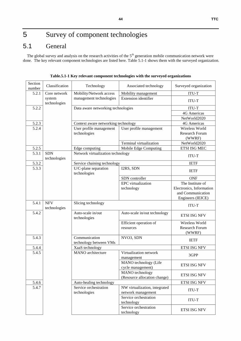
TTC 44
5 Survey of component technologies
5.1 General
The global survey and analysis on the research activities of the 5th
generation mobile communication network were
done. The key relevant component technologies are listed here. Table 5.1-1 shows them with the surveyed organization.
Table.5.1-1 Key relevant component technologies with the surveyed organizations
Section
number Classification Technology Associated technology Surveyed organization
5.2.1 Core network
system
technologies
Mobility/Network access
management technologies
Mobility management ITU-T
Extension identifier ITU-T
5.2.2 Data aware networking technologies ITU-T
4G Americas
NetWorld2020
5.2.3 Context aware networking technology 4G Americas
5.2.4 User profile management
technologies
User profile management Wireless World
Research Forum
(WWRF)
Terminal virtualization NetWorld2020
5.2.5 Edge computing Mobile Edge Computing ETSI ISG MEC
5.3.1 SDN
technologies
Network virtualization technology ITU-T
5.3.2 Service chaining technology IETF
5.3.3 U/C-plane separation
technologies
I2RS, SDN IETF
SDN controller ONF
EPC virtualization
technology
The Institute of
Electronics, Information
and Communication
Engineers (IEICE)
5.4.1 NFV
technologies
Slicing technology ITU-T
5.4.2 Auto-scale in/out
technologies
Auto-scale in/out technology ETSI ISG NFV
Efficient operation of
resources
Wireless World
Research Forum
(WWRF)
5.4.3 Communication
technology between VMs
NVO3, SDN IETF
5.4.4 XaaS technology ETSI ISG NFV
5.4.5 MANO architecture Virtualization network
management 3GPP
MANO technology (Life
cycle management) ETSI ISG NFV
MANO technology
(Resource allocation change) ETSI ISG NFV
5.4.6 Auto-healing technology ETSI ISG NFV
5.4.7 Service orchestration
technologies
NW virtualization, integrated
network management ITU-T
Service orchestration
technology ITU-T
Service orchestration
technology ETSI ISG NFV

TTC 45
5.4.8 SDN/NFV integration
technologies
SDN/NFV integration
technology IETF
SDN/NFV integration
technology
ARIB 2020 and Beyond
Ad Hoc
Secure boot, attestation,
remote attestation, trust
chain
ETSI
5.5.1 MBH system
technologies
High reliability
technology
Carrier-grade Ethernet
system
MEF (Metro Ethernet
Forum)
5.5.2 Clock synchronization
technology
Clock distribution system
(limited to UDWDM-
OFDM)
IEEE/OSA
5.6.1 MFH
technologies
C-RAN transmission
technologies
MFH transmission system
(Change of functional
allocations between RRH &
BBU: Layer 1 should be in
RRH.)
IEICE
RU/DU functional splitting NGMN
5.6.2 Data compression
technology
Radio data dynamic
compression technology IEEE/OSA
5.6.3 TDM-PON technologies Bandwidth allocation control
(DBA: Dynamic
Bandwidth Allocation)
IEEE/OSA
Bandwidth allocation control IEEE ICC
Radio data compression IEEE ICC
C-RAN functional splitting IEEE ICC
5.7.1 Optical
transmission
technologies
Modulation technologies DMT system
IEICE
UDWDM-OFDM system IEEE/OSA
5.7.2 Space Division
Multiplexing technology
MC-SMF transmission
system (Multi Core-Single
Mode Fiber)
IEEE
5.7.3 Wavelength Division
Multiplexing technology
Flexible grid allocation
system IEEE
5.8.1 Other
technologies
NW power saving
technologies
Optical switching system ITU-T
Sleep function ITU-T
Traffic control (minimum) ITU-T
5.8.2 Economic incentive
technology
SLA management, etc. ITU-T
5.8.3 Integrated network
management
ITU-T
5.8.4 NW optimization Optimum control of resource
allocations ITU-T
Optimum control of network
functions ITU-T
5.8.5 Reliability improvement
technology
ITU-T
5.8.6 Security technologies ITU-T
Wireless World
Research Forum
(WWRF)

TTC 46
5.2 Core network system technologies
5.2.1 Mobility/Network access management technologies
Component technology Mobility management
(1) Features Huge amount of nodes (communication devices) shall be able to easily move at
high speed and in large scale in various kinds of networks (e.g., networks for
mobile phones and wireless LAN, etc.) where they move dynamically. Also,
regardless of the mobility characteristics of nodes, mobile service shall be
supported.
(2) Issues to be solved by
this technology
It is difficult to easily offer services combining cells of multiple types and
RAT/WiFi of multiple types to users.
(3) Benefits of this
technology
By providing access optimized to radio approach status of terminals, service
connectivity will be improved.
(4) Maturity level of this
technology/ issues to be
worked out
Provision of various radio access for terminals and introduction of optimized
management system
(5) Organization for this
study
ITU-T
(6) Reference ITU-T Y.3001
Component technology Extension identifier
(1) Features Configuration of new identifiers that can scalably support mobility and data
access shall be provided
(2) Issues to be solved by
this technology
Support for control combining cells of multiple types and RAT/WiFi of multiple
types. Support for inter-domain move and various terminals.
(3) Benefits of this
technology
By defining new identification structure to enable networking between host and
data efficiently, dynamic mapping of ID and dynamic mapping between data and
host IDs are possible.
(4) Maturity level of this
technology/ issues to be
worked out
The overview has already been described in Y.3031.
(5) Organization for this
study
ITU-T
(6) Reference ITU-T Y.3001, Y.3031
5.2.2 Data aware networking technologies
Component technology Data awareness tetworking technology
(1) Features It shall be possible to process massive amount of data optimally and efficiently.
For the purpose, access method has been designed considering the location of
the data in the center. However, in the future networks, access method will be
established not focusing on the location but on the data itself.
(2) Issues to be solved by
this technology
Since access method was set considering the location of data in the center,
access procedure was complicated, which increased access duration.
(3) Benefits of this
technology
Reduction of time required for data access, and simplification of the procedure
(4) Maturity level of this
technology/ issues to be
worked out
The overview has already been described in Y.3033.
(5) Organization for this
study
ITU-T
(6) Reference ITU-T Y.3001, Y.3033

TTC 47
Component technology Data aware networking technology
(1) Features Communication will be made not with addressing based on the location but with
the content name, etc., without the need to know where the communication
counterpart is. In addition, end-to-end communication is not needed because
contents are assumed to be cached.
(2) Issues to be solved by
this technology
The technology will adapt to the situation where the main purpose of
communication has changed from voice call and other one-on-one
communications to data distribution/acquisition.
(3) Benefits of this
technology
Streamlined distribution and optimized resources/facilities can be expected.
(4) Maturity level of this
technology/ issues to be
worked out
Ideas under consideration
(5) Organization for this
study
4G Americas
(6) Reference 4G Americas, 4G Americas' Recommendations on 5G Requirements and
Solutions, OCT 2014
Component technology Data aware networking technology (1) Features Networking based not on the location but on the name will be realized.
Communication will be made by naming contents, users, devices, etc. and
dynamically linking them.
(2) Issues to be solved by
this technology
Since the communication architecture is not based on the location, mobility
management is essentially not needed. Multicast is made easily, too.
(3) Benefits of this
technology
Possible to efficiently distribute information. In addition, delay in distribution
will be smaller with content acquisition from a cache near the user.
(4) Maturity level of this
technology/ issues to be
worked out
Ideas under consideration
(5) Organization for this
study
NetWorld2020
(6) Reference NetWorld2020 ETP 5G: Challenges, Research Priorities, and Recommendations
5.2.3 Context aware networking technology
Component technology Context aware networking technology
(1) Features Environment where the network autonomously offers optimal services by
mapping service attributes to functions based on the network environment,
subscriber and device information, application requirements, operator policies,
etc.
(2) Issues to be solved by
this technology
Resource deployment can meet various requirements, as compared to the
offering of similar communication services not based on the characteristics.
(3) Benefits of this
technology
Dynamic service offering based on the characteristics of the device/application.
Optimization of CAPEX.
(4) Maturity level of this
technology/ issues to be
worked out
An issue has been raised with the security about context collection on the user
side.
(5) Organization for this
study
4G Americas
(6) Reference 4G Americas, 4G Americas' Recommendations on 5G Requirements and
Solutions, OCT 2014

TTC 48
5.2.4 User profile management technologies
Component technology User profile management
(1) Features The concept of User Profile is that users use the three classifications
(Private/Professional/Casual) of Virtual Identity (VID). They have been studied
in the ETSI, 3GPP, Liberty Alliance, W3C, etc., and SSO by identity providers,
decentralized Open ID (however, any authentication methods not defined),
Generic User Profile (ETSI STF342), etc. have been defined.
(2) Issues to be solved by
this technology
The concepts are:
- Profile Management Framework integrated by a Personalization & Identity
provider for the same Profile Management (for 3rd parties and others, too)
- User Profile expansion in an application and
(3) Benefits of this
technology
It will be easy to offer M2M and other new services and to manage multiple
User Profiles e.g. in an application.
(4) Maturity level of this
technology/ issues to be
worked out
The study in ETSI, which was similar to that conducted originally by TISPAN,
was documented in the GS INS series. ITS standardized the technology in TS
102 941.
Identity Management is under study in ITU-T SG17, too.
(5) Organization for this
study
Wireless World Research Forum (WWRF)
(6) Reference WWRF Outlook 3 (User Profiles, Personalization & Privacy)
Component technology Terminal virtualization
(1) Features A terminal that is logically divided to offer multiple separate services
(2) Issues to be solved by
this technology
Currently, different terminals are used to set different security policies and uses
(e.g. for work and personal use), which is not convenient.
(3) Benefits of this
technology
Offering of a function needed for the user to simultaneously access multiple
services or access networks. For example, a terminal will be able to be logically
divided for work and personal use in the BYOD environment, too.
(4) Maturity level of this
technology/ issues to be
worked out
Ideas under consideration
(5) Organization for this
study
NetWorld2020
(6) Reference NetWorld2020 ETP 5G: Challenges, Research Priorities, and Recommendations
5.2.5 Edge computing technology
Component technology Mobile edge computing technology
(1) Features Technology to install platform that has IT and cloud computing capability on
radio access networks close to mobile subscribers. Also, the technology provides
API for the third party to use this platform function.
(2) Issues to be solved by
this technology
This technology provides mobile subscribers with simple, secure and flexible
access. It is a measure to solve degradation of response due to mobile traffic
increase.
(3) Benefits of this
technology
This technology will improve responsibility to mobile subscribers and accelerate
contents, service and application. Similar to the direct access to real-time radio
network information (subscriber location, cell load, etc.) that is used for
application and services to provide context-related services, this technology will
enable provision of service environment of broad band with extremely low
latency for application developers and contents providers.
(4) Maturity level of this
technology/ issues to be
worked out
White paper was issued (in September 2014).
(5) Organization for this
study
ETSI ISG MEC
(6) Reference ETSI ISG MEC White paper

TTC 49
5.3 SDN technologies
5.3.1 Network virtualization technology
Component technology Network virtualization technology
(1) Features A technology that makes multiple networks that are logically
independent out of one physical network resource. Also, this technology
is able to handle multiple physical network resources as one network resource by
virtually multiplexing them.
(2) Issues to be solved by
this technology
Difficult to flexibly respond to various requirements of networking functions
needed for various service applications
(3) Benefits of this
technology
More streamlined and flexible network management
Quick introduction of new functions/services ensured
(4) Maturity level of this
technology/ issues to be
worked out
High-level requirements and architecture have been defined.
(5) Organization for this
study
ITU-T
(6) Reference ITU-T Y.3300
5.3.2 Service chaining Technology
Component technology Service chaining technology
(1) Features Definition of a protocol for service chaining (SDN control), including the
method for marking service attributes (providing metadata)
(2) Issues to be solved by
this technology
Realization of flexible service chaining, enabling both fully central (SDN)
network control and partial & decentralized control
(3) Benefits of this
technology
Currently it is restricted to simple sorting based on the static marking
information only, but this technology is expected to make it possible to define a
flexible behavior depending on the application in the network.
(4) Maturity level of this
technology/ issues to be
worked out
Although defining the protocol is not yet completed, it is under relatively
detailed discussion. Since it is an individual protocol, there is a concern that the
granularity is too fine as an ad-hoc item. It is preferable to refer to it.
(5) Organization for this
study
IETF
(6) Reference draft-boucadair-sfc-requirements,RFC 7364, RFC 7365
5.3.3 U/C-plane Separation Technologies
Component technology I2RS, SDN
(1) Features Definition of a protocol for SDN-like control mainly about routing
(2) Issues to be solved by
this technology
Realization of SDN-like management and control about (IP) routing and
forwarding
(3) Benefits of this
technology
This SDN approach is expected to make it possible to openly program routing,
forwarding and other functions that are basically assumed to autonomously
operate with distributed protocols.
(4) Maturity level of this
technology/ issues to be
worked out
The architecture, use cases, etc. are under discussion.
(5) Organization for this
study
IETF
(6) Reference draft-ietf-i2rs-architecture,RFC 7364, RFC 7365
Component technology SDN controller
(1) Features Central management of traffic in mobile networks in a virtual manner

TTC 50
(2) Issues to be solved by
this technology
- Load balancing
- Content filtering
- Policy management and implementation
- Disaster measures and recovery
- Mobile traffic offloading and roaming
- Optimal NW capacity allocation based on the content
- Traffic optimization
(3) Benefits of this
technology
Optimal control of the above (e.g. load balancing, content filtering, traffic
optimization) enabled by central management
(4) Maturity level of this
technology/ issues to be
worked out
The concept has just been described in white papers. The details of control and
scalability need to be verified.
(5) Organization for this
study
ONF
(6) Reference ONF White Paper “Software-Defined Networking : The New Norm for
Networks”
Component technology EPC virtualization technology
(1) Features System to take control with the OF-mpc protocol, equipped with the 3GPP-
defined interface as well as with an SDN controller and multiple switches in the
S-GW/P-GW
(2) Issues to be solved by
this technology
There is much higher traffic volume for some hours/in some areas, caused by
traffic changes affected by the time/geographical location. A technology is
needed to help with flexible response to traffic changes and to enable static IP
address routing in the mobile networks to be flexibly changed.
(3) Benefits of this
technology
Efficient use of resources leading to a reduction in costs and power consumption
(4) Maturity level of this
technology/ issues to be
worked out
[Maturity level]
SDN-based mobile networks have been prototyped. A reduction in the S-GW/P-
GW traffic volumes and other benefits have been verified in simulations with a
path that only offloads video signaling.
[Issue]
Integration of SDN controllers
(5) Organization for this
study
IEICE
(6) Reference Tutorial BT-1-5 for NEC/2014 Communication Society Conference
5.4 NFV technologies
5.4.1 Slicing technologies
Component technology Slicing technology
(1) Features Network virtualization technology to improve the usability of networks by
dividing (slicing) a network into multiple virtual networks and enabling each
network to be separately managed.
(2) Issues to be solved by
this technology
Needed to physically add new facilities when building a new network
(3) Benefits of this
technology
Efficient use of limited physical network resources, leading to a reduction in
CAPEX.
(4) Maturity level of this
technology/ issues to be
worked out
Requirements are already described in .3011.
(5) Organization for this
study
ITU-T
(6) Reference ITU-T Y.3001, Y.3011, Y.3012

TTC 51
5.4.2 Auto-scale in/out technologies
Component technology Auto-scale in/out technology
(1) Features Resource will be optimally deployed based on the real-time monitoring of
resource consumption in the virtual network.
(2) Issues to be solved by
this technology
Automatic optimization of network resource deployment
(3) Benefits of this
technology
Easy to change the size and layout of resources in the virtualized NW.
Automatic and real-time network resource optimization controlled by software,
based on the actual traffic status and service requirements.
(4) Maturity level of this
technology/ issues to be
worked out
Requirements in ETSI ISG NFV Phase1 will be standardized in the relevant
SDO. Phase2 might have a revision.
(5) Organization for this
study
ETSI ISG NFV
(6) Reference ETSI ISG NFV / Network Functions Virtualisation – Introductory White Paper
Component technology Efficient operation of resources
(1) Features Assumption of time varying traffic distribution:
- During the busy hour, 20% of voice and 25% of non-voice
- 50GBps/km2 of throughput is needed in a highly dense region.
- 2.08Gbit/s/RAN node (2.09Tbit/s/IP-Backbone) is needed in the transport NW.
(2) Issues to be solved by
this technology
Proposal of applying Dynamic Resource Management and Self Configuration/
Self Optimization to Core Network to respond to local traffic changes and an
increase in the number of node connections
(3) Benefits of this
technology
A failure can be prevented from bursting e.g. due to local traffic changes.
(4) Maturity level of this
technology/ issues to be
worked out
Dynamic Resource Management can be realized by applying NFV and other
technologies. Using wireless backhaul or others is under consideration in the
transport field.
(5) Organization for this
study
Wireless World Research Forum (WWRF)
(6) Reference WWRF Outlook 7 (Requirements and vision for NG-Wireless)
5.4.3 Communication technologies between VMs
Component technology NVO3, SDN
(1) Features Tunneling protocol to create an overlay between VM or other entities
(2) Issues to be solved by
this technology
Realization of:
- Appropriate forwarding (e.g. load balancing) in an underlay, based on the
overlay flow
- Flexible ID space where VM migration is considered, too
(3) Benefits of this
technology
The scale of a service-chained virtual network is expected to be maintained,
which is difficult to realize with the existing tunneling technology only.
(4) Maturity level of this
technology/ issues to be
worked out
The maturity level is high because the details are being fixed. Since it is an
individual protocol, there is a concern that the granularity is too fine as an ad-hoc
item.
(5) Organization for this
study
IETF
(6) Reference IETF/RFC 7364, RFC 7365
5.4.4 XaaS technologies
Component technology XaaS technologies
(1) Features Provision of a single platform that can be used for various services and by
multiple network users
(2) Issues to be solved by
this technology
More flexible cancellation of a NW function

TTC 52
(3) Benefits of this
technology
Various services (e.g. IaaS, PaaS, SaaS) offered and resources shared among
multiple network users (e.g. service providers, MVNO users) in a platform
generated by comprehensively virtualizing the core NW, leading to an reduction
in facilities costs
(4) Maturity level of this
technology/ issues to be
worked out
Requirements in ETSI ISG NFV Phase1 will be standardized in the relevant
SDO. Phase2 might have a revision.
(5) Organization for this
study
ETSI ISG NFV
(6) Reference ETSI ISG NFV / Network Functions Virtualisation – Introductory White Paper
5.4.5 MANO Architecture
Component technology Virtualized NW management
(1) Features Study of management of virtualized 3GPP networks
(2) Issues to be solved by
this technology
Summarization of how the NW management architecture and functions relate to
each other in the virtualized NW, existing (non-virtualized) NW and a
combination of them
(3) Benefits of this
technology
Migration to the virtualization environment is expected to be made easy because
it will likely be possible to manage virtualized 3GPP networks in a method
unified by standardization and a combination of virtualized and existing
networks will be considered, too.
(4) Maturity level of this
technology/ issues to be
worked out
This technology started to be studied in August 2014. The version number of the
technical report summarizing what was studied is 0.3.0 as of January 2015.
(5) Organization for this
study
3GPP
(6) Reference 3GPP SA WG5 / TR 32.842
(http://www.3gpp.org/DynaReport/32842.htm)
Component technology MANO (Life cycle management)
(1) Features Lifecycle of software functions in the hierarchical network is managed by the
operation management system.
(2) Issues to be solved by
this technology
Reduction in time taken to create a service
(3) Benefits of this
technology
Time required to offer (add/modify) a service reduced with the comprehensively
virtualized core NW and the integrated operation management system
(4) Maturity level of this
technology/ issues to be
worked out
Requirements in ETSI ISG NFV Phase1 will be standardized in the relevant
SDO. Phase2 might have a revision.
(5) Organization for this
study
ETSI ISG NFV
(6) Reference ETSI ISG NFV / Network Functions Virtualisation – Introductory White Paper
and – Update White Paper"
Component technology MANO (Resource deployment change)
(1) Features Flexibility in changing the resource layout in the network will be enhanced by
network virtualization.
(2) Issues to be solved by
this technology
Realization of flexible network operations that meet the needs of maintenance
personnel
(3) Benefits of this
technology
Easy to change the scale and layout of resources in the virtualized NW. Possible
to quickly change the service scale based on the situation and plan as requested by
maintenance personnel.
(4) Maturity level of this
technology/ issues to be
worked out
Requirements in ETSI ISG NFV Phase1 will be standardized in the relevant SDO.
Phase2 might have a revision.
(5) Organization for this
study
ETSI ISG NFV
(6) Reference ETSI ISG NFV / Network Functions Virtualisation – Introductory White Paper

TTC 53
5.4.6 Auto-healing technology
Component technology Auto-healing technology
(1) Features Resiliency and stability will be provided so that no single point of failure shall
cause failures of entire NW and offering and continuity of services shall be
ensured.
(2) Issues to be solved by
this technology
Improvement of fault tolerance
(3) Benefits of this
technology
NW made more reliable with flexible changes in the layout of services and
resources during a HW failure in the virtualized NW
(4) Maturity level of this
technology/ issues to be
worked out
Requirements in ETSI ISG NFV Phase1 will be standardized in the relevant
SDO. Phase2 might have a revision.
(5) Organization for this
study
ETSI ISG NFV
(6) Reference Network Functions Virtualisation – Update White Paper
5.4.7 Service orchestration technologies
Component technology NW virtualization , Integrated network management
(1) Features Acceptance of various network services with different traffic characteristics and
behaviors (e.g. small data sent from a huge number of terminals, very high-
precision image signals sent to a specific location). In addition, connections
made from a huge number of devices (e.g. sensor terminals) to the network.
(2) Issues to be solved by
this technology
Efficient accommodation of terminals with different requirements (terminals
different in mobility and delay tolerance). Quick introduction of new
functions/services ensured
(3) Benefits of this
technology
Accommodation of various terminals/services different in network
characteristics. Reduction in time taken to introduce a new function/service
(4) Maturity level of this
technology/ issues to be
worked out
Realization of requirements/architecture
(5) Organization for this
study
ITU-T
(6) Reference Y.3001: Future networks: Objectives and design goals
Component technology Service orchestration technology
(1) Features Functional flexibility to support new services that are launched upon request of
users. Due to the impossibility of realizing a network meeting any user’s
requirements both at present and in the future, a technology enabling dynamic
changes in network functions will be developed to make up for it.
(2) Issues to be solved by
this technology
There is a restriction in the NW’s function offering, and in order to launch a new
service, development, construction, etc. are needed e.g. to add new facilities. New
services need be carefully introduced so that they will not have an impact on the
existing services.
(3) Benefits of this
technology
Easy to quickly offer a new service because it will be possible to add new
functions flexibly to the existing network infrastructure
(4) Maturity level of this
technology/ issues to be
worked out
Realization of requirements/architecture
(5) Organization for this
study
ITU-T
(6) Reference ITU-T Y.3001
Component technology Service orchestration technology
(1) Features General-purpose equipment will be applied due to the reduction in the existing
equipment.
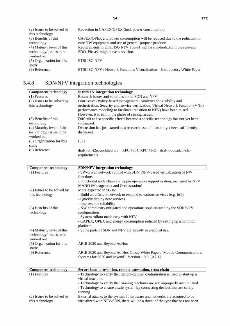
TTC 54
(2) Issues to be solved by
this technology
Reduction in CAPEX/OPEX (incl. power consumption)
(3) Benefits of this
technology
CAPEX/OPEX and power consumption will be reduced due to the reduction in
core NW equipment and use of general-purpose products
(4) Maturity level of this
technology/ issues to be
worked out
Requirements in ETSI ISG NFV Phase1 will be standardized in the relevant
SDO. Phase2 might have a revision.
(5) Organization for this
study
ETSI ISG NFV
(6) Reference ETSI ISG NFV / Network Functions Virtualisation – Introductory White Paper
5.4.8 SDN/NFV integration technologies
Component technology SDN/NFV integration technology
(1) Features Research issues and solutions about SDN and NFV
(2) Issues to be solved by
this technology
Four issues (Policy-based management, Analytics for visibility and
orchestration, Security and service verification, Virtual Network Function (VNF)
performance modeling to facilitate transition to NFV) have been raised.
However, it is still in the phase of raising issues.
(3) Benefits of this
technology
Difficult to list specific effects because a specific technology has not yet been
confirmed.
(4) Maturity level of this
technology/ issues to be
worked out
Discussion has just started as a research issue. It has not yet been sufficiently
discussed.
(5) Organization for this
study
IETF
(6) Reference draft-ietf-i2rs-architecture,RFC 7364, RFC 7365,draft-boucadair-sfc-
requirements
Component technology SDN/NFV integration technology
(1) Features - SW-driven network control with SDN, NFV-based virtualization of NW
functions
- Functional node chain and upper operation support system, managed by NFV
MANO (Management and Orchestration)
(2) Issues to be solved by
this technology
More expected in 5G to:
- Build an efficient network to respond to various services (e.g. IoT)
- Quickly deploy new services
- Improve the reliability
(3) Benefits of this
technology
- NW complexity mitigated and operations sophisticated by the SDN/NFV
configuration
- System rollout made easy with NFV
- CAPEX, OPEX and energy consumption reduced by setting up a common
platform
(4) Maturity level of this
technology/ issues to be
worked out
- Some parts of SDN and NFV are already in practical use.
(5) Organization for this
study
ARIB 2020 and Beyond AdHoc
(6) Reference ARIB 2020 and Beyond Ad Hoc Group White Paper, "Mobile Communications
Systems for 2020 and beyond", Version 1.0.0, [A7.1]
Component technology Secure boot, attestation, remote-attestation, trust chain
(1) Features - Technology to verify that the pre-defined configuration is used to start up a
virtual machine.
- Technology to verify that running machines are not improperly manipulated.
- Technology to ensure a safe system by connecting devices that are safely
running
(2) Issues to be solved by
this technology
External attacks to the system. If hardware and networks are assumed to be
virtualized with NFV/SDN, there will be a threat of the type that has not been

TTC 55
considered before.
(3) Benefits of this
technology
Services can be safely offered.
(4) Maturity level of this
technology/ issues to be
worked out
[Maturity]
Secure Boot and other individual technologies are getting matured whereas e.g.
analyzing a threat to the system has not yet started.
[Issue]
Both the architecture and individual implementation need to be verified.
(5) Organization for this
study
ETSI
(6) Reference ETSI GS NFV-SEC 003 V1.1.1 (2014-12)
Network Functions Virtualisation (NFV); NFV Security; Security and Trust
Guidance
5.5 MBH system technologies
5.5.1 High reliability technology
Component technology Carrier-grade Ethernet system
(1) Features The MEF creates the carrier-grade Ethernet technique specification applicable to
communication networks provided by carriers as an MEF standard, by adding
OAM, etc. to the Ethernet technology specified in IEEE802.3. As part of the
effort, the MEF has standardized the carrier-grade Ethernet technology for
mobile backhaul as part of the MEF22 series.
(2) Issues to be solved by
this technology
Contribution to cost reduction for mobile backhaul construction by applying the
carrier-grade Ethernet technology widely used in core/access networks of
carriers to mobile backhaul networks.
(3) Benefits of this
technology
Because carrier-grade Ethernet is able to respond to the change of transmission
capacity and the number of nodes with QoS, and also because its boundary of
responsibility is clear and it has service management completely, it is possible to
build efficient and highly reliable mobile backhaul network at low cost.
(4) Maturity level of this
technology/ issues to be
worked out
Current MEF22.1 is created based on 4G (LTE), and its Amendment 1 supports
small cells. Because functions such as transmission capacity, etc. are specified in
accordance with core networks, the technology can be supported at an early
stage once the 5G specification is determined in 3GPP.
(5) Organization for this
study
MEF (Metro Ethernet Forum)
(6) Reference MEF22.1 Overview, MEF22.1, MEF22.1 Amendment 1
5.5.2 Clock synchronization technology
Component technology Clock distribution system (limited to UDWDM-OFDM)
(1) Features Technology to distribute/generate sync clock necessary to accommodate
synchronous Ethernet in the UDWDM-OFDMA system, one of the mobile
backhaul solutions in the future.
(2) Issues to be solved by
this technology
In addition to basic sync functions such as handoff between base stations and
carrier frequency accuracy, system-level synchronization is necessary for
OFDM. In recent years, the clock distribution/generation technology for single-
wavelength direct detection OFDM system has been presented. However, there
are still some issues for multi wavelength such as inhibit of beats causing
spectrum efficiency degradation.
(3) Benefits of this
technology
In this paper, by applying SSB (Single Sideband Modulation) and the envelop
detection technique that does not require and DSP, sync clock 50MHz can be
distributed and generated under 30Gbps, 24.56GHz and 40Km transmission
conditions, which can contribute to application to mobile backhaul.
(4) Maturity level of this
technology/ issues to be
worked out
[Maturity level]
At a stage of theory verification at lab (according to document)
[Issue]
Standardization of distribution/generation method

TTC 56
(5) Organization for this
study
IEEE/OSA
(6) Reference Novel Synchronous Clock Distribution and Recovery for High-Speed UDWDM-
OFDMA-based Mobile Backhaul
5.6 MFH system technologies
5.6.1 C-RAN transmission technology
Component technology MFH transmission system (Reference point change: Layer 1 processing at
APs)
(1) Features Retain the coding function, move Layer 1 process to remote AP, split data for
each OFDM symbol for transmission.
(2) Issues to be solved by
this technology
With the optical remote method using CPRI, the MFH data rate gets huge,
making implementation difficult financially.
(3) Benefits of this
technology
Reduction of transmission delay in MFH
(4) Maturity level of this
technology/ issues to be
worked out
[Maturity level]
At a stage of method proposal
[Issue]
Method comparison is necessary
(5) Organization for this
study
Institute of Electronics, Information and Communication Engineers
(6) Reference NEC/2014 IEICE Society Conference (Tutorial BT-1-3)
Component technology RU/DU functional splitting
(1) Features Functional split points for RU (RRH) and DU (BBU) in the C-RAN
configuration are studied and redefined.
(2) Issues to be solved by
this technology
The objective is to optimize the tradeoff between DU-RU data communication
band and C-RAN advantages (maximized CoMP effect, resource share,
concentrated load, etc), and 5 types of split point are being studied.
(3) Benefits of this
technology
There is a tradeoff between advantages (effect) and disadvantages depending on
the selection of functional split points.
For example, in the case of the conventional split points (RF: AD/DA,
compression, DU: L1, L2, L3), while great benefit can be obtained from C-RAN,
high-capacity data communication bandwidth is required. On the other hand, if
the split point is set between L1 and L2, although the bandwidth can be reduced,
the C-RAN benefit becomes small.
(4) Maturity level of this
technology/ issues to be
worked out
There has been no method presented that can achieve both data communication
band reduction and maximization of C-RAN benefit. Other split points are also
available, so further comparison study is required.
(5) Organization for this
study
NGMN (Next Generation Mobile Network)
(6) Reference NGMN / “Suggestions on potential solutions to C-RAN”, 4.2.3 Allocation of
signal processing functions between RU and DU/DU cloud
5.6.2 Data compression technologies
Component technology Wireless data compression technologies
(1) Features IQ data compression shall be processed according to the frequency bandwidth
used for wireless signals.
(2) Issues to be solved by
this technology
Ultra high-speed and huge number of line connections in mobile front-haul cause
steep rise in the cost. General base-band signal transfer is based on the fixed rate,
unsuitable for application of shared network TDM-PON.
(3) Benefits of this
technology
Statistical multiplexing effect can be expected with dynamic compression of
wireless signals, which can increase the effectiveness of TDM-PON applied to
mobile front-backhaul.
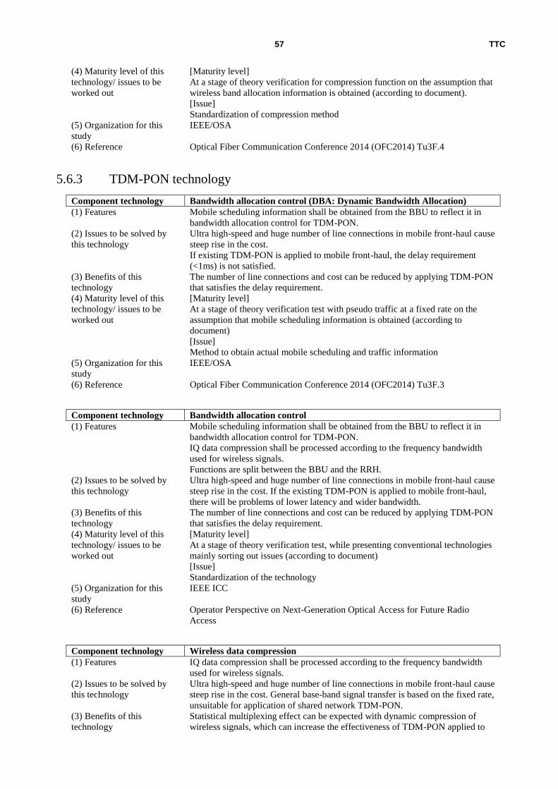
TTC 57
(4) Maturity level of this
technology/ issues to be
worked out
[Maturity level]
At a stage of theory verification for compression function on the assumption that
wireless band allocation information is obtained (according to document).
[Issue]
Standardization of compression method
(5) Organization for this
study
IEEE/OSA
(6) Reference Optical Fiber Communication Conference 2014 (OFC2014) Tu3F.4
5.6.3 TDM-PON technology
Component technology Bandwidth allocation control (DBA: Dynamic Bandwidth Allocation)
(1) Features Mobile scheduling information shall be obtained from the BBU to reflect it in
bandwidth allocation control for TDM-PON.
(2) Issues to be solved by
this technology
Ultra high-speed and huge number of line connections in mobile front-haul cause
steep rise in the cost.
If existing TDM-PON is applied to mobile front-haul, the delay requirement
(<1ms) is not satisfied.
(3) Benefits of this
technology
The number of line connections and cost can be reduced by applying TDM-PON
that satisfies the delay requirement.
(4) Maturity level of this
technology/ issues to be
worked out
[Maturity level]
At a stage of theory verification test with pseudo traffic at a fixed rate on the
assumption that mobile scheduling information is obtained (according to
document)
[Issue]
Method to obtain actual mobile scheduling and traffic information
(5) Organization for this
study
IEEE/OSA
(6) Reference Optical Fiber Communication Conference 2014 (OFC2014) Tu3F.3
Component technology Bandwidth allocation control
(1) Features Mobile scheduling information shall be obtained from the BBU to reflect it in
bandwidth allocation control for TDM-PON.
IQ data compression shall be processed according to the frequency bandwidth
used for wireless signals.
Functions are split between the BBU and the RRH.
(2) Issues to be solved by
this technology
Ultra high-speed and huge number of line connections in mobile front-haul cause
steep rise in the cost. If the existing TDM-PON is applied to mobile front-haul,
there will be problems of lower latency and wider bandwidth.
(3) Benefits of this
technology
The number of line connections and cost can be reduced by applying TDM-PON
that satisfies the delay requirement.
(4) Maturity level of this
technology/ issues to be
worked out
[Maturity level]
At a stage of theory verification test, while presenting conventional technologies
mainly sorting out issues (according to document)
[Issue]
Standardization of the technology
(5) Organization for this
study
IEEE ICC
(6) Reference Operator Perspective on Next-Generation Optical Access for Future Radio
Access
Component technology Wireless data compression
(1) Features IQ data compression shall be processed according to the frequency bandwidth
used for wireless signals.
(2) Issues to be solved by
this technology
Ultra high-speed and huge number of line connections in mobile front-haul cause
steep rise in the cost. General base-band signal transfer is based on the fixed rate,
unsuitable for application of shared network TDM-PON.
(3) Benefits of this
technology
Statistical multiplexing effect can be expected with dynamic compression of
wireless signals, which can increase the effectiveness of TDM-PON applied to

TTC 58
mobile front-backhaul.
(4) Maturity level of this
technology/ issues to be
worked out
[Maturity level]
At a stage of theory verification test for compression function on the assumption
that wireless bandwidth allocation information is obtained (according to
document)
[Issue]
Standardization of compression method
(5) Organization for this
study
IEEE ICC
(6) Reference Operator Perspective on Next-Generation Optical Access for Future Radio
Access
Component technology C-RAN functional splitting
(1) Features Functions shall be split between the BBU and the RRH.
(2) Issues to be solved by
this technology
Ultra high-speed and huge number of line connections in mobile front-haul cause
steep rise in the cost. General base-band signal transfer is based on the fixed rate,
unsuitable for application of shared network TDM-PON.
(3) Benefits of this
technology
Statistical multiplexing effect can be expected with dynamic compression of
wireless signals, which can increase the effectiveness of TDM-PON applied to
mobile front-backhaul.
(4) Maturity level of this
technology/ issues to be
worked out
[Maturity level]
At a stage of theory verification test for compression function on the assumption
that wireless bandwidth allocation information is obtained (according to
document)
[Issue]
Standardization of compression method
(5) Organization for this
study
IEEE ICC
(6) Reference Operator Perspective on Next-Generation Optical Access for Future Radio Access
5.7 Optical transmission technology
5.7.1 Modulation technologies
Component technology DMT system
(1) Features DMT modulating multiple subcarriers, only with the strength element without
using the phase element. Each subcarrier’s modulation level dependent on the
transmission quality.
(2) Issues to be solved by
this technology
TDM-PON has a delay issue and WDM-PON is not economical.
(3) Benefits of this
technology
Possible to reduce costs in ultra high speed transmission in MFH
(4) Maturity level of this
technology/ issues to be
worked out
[Maturity level]
Experimental verification is underway for DML transmission (100 Gbps or more
for 10 km). DML itself is a technology used for ADSL.
[Issue]
Comparison with other methods needed
(5) Organization for this
study
IEICE
(6) Reference Fujitsu/Tutorial BT-1-4 for 2014 Communication Society Conference
Component technology UDWDM-OFDM system
(1) Features Single Sideband Modulation method that enables the distribution and
reproduction of a synchronous 50MHz clock
(2) Issues to be solved by
this technology
OFDM needs system-level synchronization as well as basic synchronization
functions such as BTS-to-BTS hand-off and carrier frequency accuracy.
Although a clock distribution and reproduction technology has recently been
presented in the OFDM system that directly demodulates single-wavelengths,

TTC 59
there are some issue with wavelength multiplexing, including the need to reduce
beats that cause a reduction in the spectral efficiency.
(3) Benefits of this
technology
When SSB (Single Sideband) modulation and envelope demodulation with no
need for DSP are applied, a synchronous 50MHz clock can be distributed and
reproduced in transmission of 30Gbps, 24.56GHz and 40km in the UDWDM-
OFDMA system. This can be expected to be applied to the mobile backhaul.
(4) Maturity level of this
technology/ issues to be
worked out
[Maturity level]
According to the reference, the principle is being verified in the lab.
[Issue]
Standardization of the distribution and reproduction method
(5) Organization for this
study
IEEE/OSA
(6) Reference Novel Synchronous Clock Distribution and Recovery for High-Speed UDWDM-
OFDMA-based Mobile Backhaul
5.7.2 Space Division Multiplex technology
Component technology MC-SMF transmission system (Multi core - Single mode fiber)
(1) Features Research report on the space division multiplexing transmission system,
summarizing advantages and disadvantages of MC-SM (Multi-Core Single-
Mode) transmission, SC-FM(Single-Core Few-Modes) transmission and MC-
FM transmission compared to SC-SM transmission
(2) Issues to be solved by
this technology
MC-SM and SC-FM are more advantageous as near-future solutions because it
has been reported that they enable long-distance transmission. However, the core
density per fiber could easily reach the limit.
(3) Benefits of this
technology
MIMO technology-based MC-FM transmission is expected to help with capacity
expansion in the future.
(4) Maturity level of this
technology/ issues to be
worked out
[Maturity level]
The results of long-distance transmission show that MC-SM is equivalent to SC-
SM. Although the distance that is experimentally verified in long-distance
transmission with MC-FM is only approx. one hundredth of that enabled with
SC-SM, successful results have already been reported on the transmission up to
the distance (40km) required for access.
[Issue]
Still in the lab level. Any field testing has not been reported. Since new fiber
installation is needed for practical use, infrastructure costs are another issue.
(5) Organization for this
study
IEEE
(6) Reference [Organization studying this technology]
Prysmian Group
[Reference]
ECOC 2014 Tu.4.1.1 Next-Generation Fibers for Space-Division-Multiplexed
Transmissions
5.7.3 Wavelength Division Multiplex technology
Component technology Flexible grid allocation system
(1) Features A technology to use frequency bands more efficiently with not fixed but variable
allocation of wavelength division multiplexing grids has been presented in future
mobile fronthaul solutions (“CWDM-like” transmission/reception method as a
short-term solution and “DWDM-like” transmission/reception method as a long-
term solution) and a future mobile backhaul solution (DWDM system).
(2) Issues to be solved by
this technology
CWDM is a technology that can be applied to the fronthaul. But since it is for
dual-core bidirectional transmission, FTTH facilities based on single-core
bidirectional transmission cannot be applied (installed fibers cannot be reused).
In DWDM (Dense Wavelength Division Multiplexing) technology applied to
core networks, 90 wavelengths are multiply transmitted, with wavelength
division multiplexing grids divided in fixed units of 50GHz. However, since
50GHz of intervals include margins and even 37.5GHz enables transmission,
further multiplexing could be possible.

TTC 60
(3) Benefits of this
technology
Reference [A]:
The following solutions are proposed:
(Short-term solution)
Technology to enable single-core bidirectional transmission by using two
wavelengths with 20nm of space between them for transmission and reception,
as a “CWDM-like” transmission/reception method
(Long-term solution evolved from the above solution)
“DWDM-like” transmission/reception method to enable passive and automatic
wavelength assignment by using “Self-seeded Reflective Semiconductor Optical
Amplifier (RSOAs)”
They can be expected to be applied to the mobile fronthaul.
Reference [B]:
If technologies including WSS (Wavelength Selective Switch) to enable an
arbitrary selection of wavelength division multiplexing grids are developed,
those grids can be variable, not fixed to 50GHz. This can be expected to be
applied to the mobile fronthaul, as more efficient high-capacity transmission.
(4) Maturity level of this
technology/ issues to be
worked out
[Maturity level]
Researches and discussion are being summarized.
[Issue]
Practicality
(5) Organization for this
study
IEEE
(6) Reference [A] Orange Labs Networks /ECOC2014 Tu.4.2.1 Things You Should Know
About Fronthaul
[B] British Telecom./ECOC2014 Mo3.1.1 Core Networks in the Flexgrid Era
5.8 Any other technologies
5.8.1 NW power saving technologies
Component technology Optical switching system
(1) Features Energy efficiency shall be maximized by effectively utilizing
device/equipment/network-level technologies and satisfy user’s requests with
minimum traffic. Device/equipment/network-level technologies shall interact
with each other to save network energy, rather than operating independently.
(2) Issues to be solved by
this technology
Consumption power increase due to increased traffic volume. 24-hour operation
causes heat generation and increases consumption power.
(3) Benefits of this
technology
Power can be saved by switching from electronic to optical switches.
(4) Maturity level of this
technology/ issues to be
worked out
The overview has been stated in Y.3021
(5) Organization for this
study
ITU-T
(6) Reference ITU-T Y.3001, Y.3021
Component technology Sleep function
(1) Features Energy efficiency shall be maximized by effectively utilizing
device/equipment/network-level technologies and satisfy users’ requests with
minimum traffic.
(2) Issues to be solved by
this technology
Consumption power increase due to increased traffic volume. 24-hour operation
causes heat generation and increases consumption power.
(3) Benefits of this
technology
Power can be saved by implementing a sleep function into network equipment.
(4) Maturity level of this
technology/ issues to be
worked out
The overview has been stated in Y.3021
(5) Organization for this ITU-T

TTC 61
study
(6) Reference ITU-T Y.3001, Y.3021
Component technology Traffic control (minimum)
(1) Features Energy efficiency shall be maximized by effectively utilizing
device/equipment/network-level technologies and satisfy users’ requests with
minimum traffic.
(2) Issues to be solved by
this technology
Consumption power increase due to increased traffic volume. 24-hour operation
causes heat generation and increases consumption power.
(3) Benefits of this
technology
Power can be saved by minimizing traffic volume using cache.
(4) Maturity level of this
technology/ issues to be
worked out
The overview has been stated in Y.3021
(5) Organization for this
study
ITU-T
(6) Reference ITU-T Y.3001, Y.3021
5.8.2 Economic incentive technology
Component technology SLA management, etc
(1) Features Designing shall be done to provide a sustainable competitive environment in
order to solve conflicts of economic interests among various stakeholders
including users, various providers, governmental institutions, and intellectual
property right holders.
(2) Issues to be solved by
this technology
Development of new network technologies due to financial reasons that are not
practically applied or sustainable.
(3) Benefits of this
technology
Network that evolves sustainably can be constructed by giving economic
incentives to all ICT stake holders.
(4) Maturity level of this
technology/ issues to be
worked out
Crystallization of requirements/architecture
(5) Organization for this
study
ITU-T
(6) Reference ITU-T Y.3001
5.8.3 Integrated network management
Component technology Integrated network management
(1) Features Management mechanism that can be efficiently operated and maintained as well
as deal with increase of services and communication. Especially, it can
efficiently and effectively process information including control data, convert
the information into relevant information or knowledge and send it to
administrators.
(2) Issues to be solved by
this technology
Management systems exist separately for each network component, which
results in poor operation efficiency. In addition, network management operation
capability depends on operators' level of skill, which requires transmission of
know-how.
(3) Benefits of this
technology
Simplified network management, flexibility and OPEX reduction. Efficient
transmission of operators’ knowledge, etc.
(4) Maturity level of this
technology/ issues to be
worked out
Crystallization of requirements/architecture
(5) Organization for this
study
ITU-T
(6) Reference ITU-T Y.3001
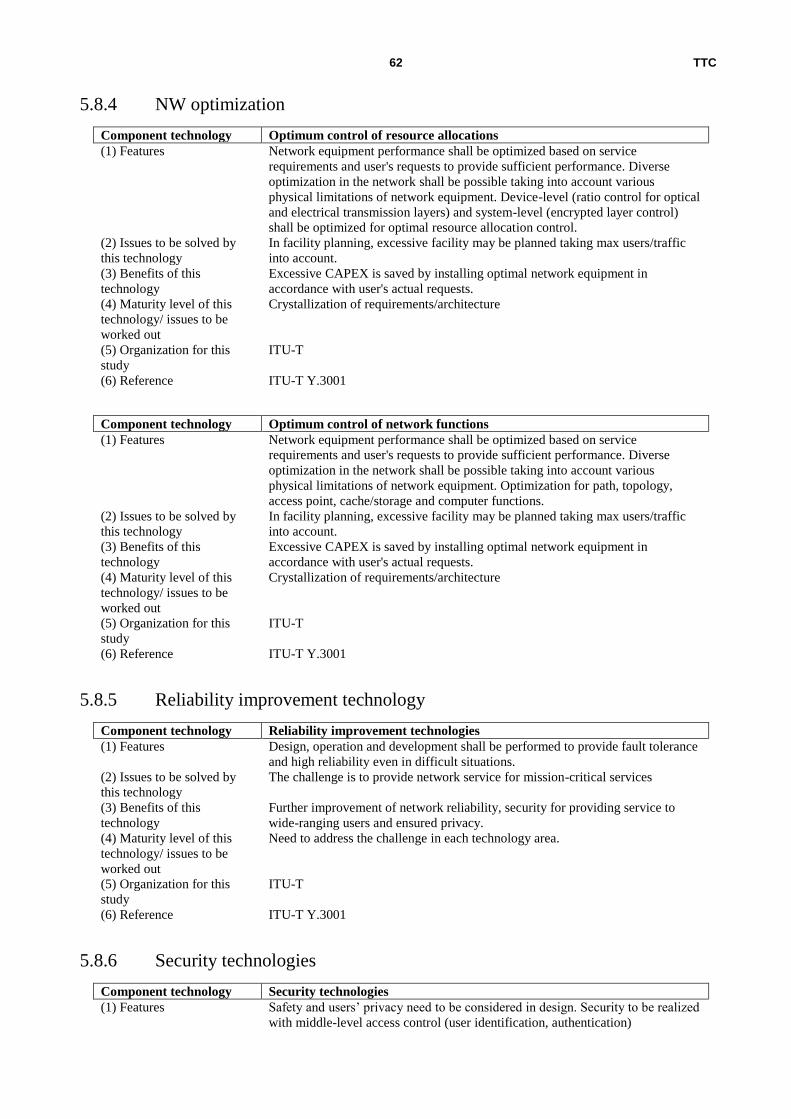
TTC 62
5.8.4 NW optimization
Component technology Optimum control of resource allocations
(1) Features Network equipment performance shall be optimized based on service
requirements and user's requests to provide sufficient performance. Diverse
optimization in the network shall be possible taking into account various
physical limitations of network equipment. Device-level (ratio control for optical
and electrical transmission layers) and system-level (encrypted layer control)
shall be optimized for optimal resource allocation control.
(2) Issues to be solved by
this technology
In facility planning, excessive facility may be planned taking max users/traffic
into account.
(3) Benefits of this
technology
Excessive CAPEX is saved by installing optimal network equipment in
accordance with user's actual requests.
(4) Maturity level of this
technology/ issues to be
worked out
Crystallization of requirements/architecture
(5) Organization for this
study
ITU-T
(6) Reference ITU-T Y.3001
Component technology Optimum control of network functions
(1) Features Network equipment performance shall be optimized based on service
requirements and user's requests to provide sufficient performance. Diverse
optimization in the network shall be possible taking into account various
physical limitations of network equipment. Optimization for path, topology,
access point, cache/storage and computer functions.
(2) Issues to be solved by
this technology
In facility planning, excessive facility may be planned taking max users/traffic
into account.
(3) Benefits of this
technology
Excessive CAPEX is saved by installing optimal network equipment in
accordance with user's actual requests.
(4) Maturity level of this
technology/ issues to be
worked out
Crystallization of requirements/architecture
(5) Organization for this
study
ITU-T
(6) Reference ITU-T Y.3001
5.8.5 Reliability improvement technology
Component technology Reliability improvement technologies
(1) Features Design, operation and development shall be performed to provide fault tolerance
and high reliability even in difficult situations.
(2) Issues to be solved by
this technology
The challenge is to provide network service for mission-critical services
(3) Benefits of this
technology
Further improvement of network reliability, security for providing service to
wide-ranging users and ensured privacy.
(4) Maturity level of this
technology/ issues to be
worked out
Need to address the challenge in each technology area.
(5) Organization for this
study
ITU-T
(6) Reference ITU-T Y.3001
5.8.6 Security technologies
Component technology Security technologies
(1) Features Safety and users’ privacy need to be considered in design. Security to be realized
with middle-level access control (user identification, authentication)

TTC 63
(2) Issues to be solved by
this technology
Identification of online users and protection of personal information. A safe and
secure online environment needs to be offered to users including children,
handicapped people and minority groups.
(3) Benefits of this
technology
- More reliable networks
- Security and privacy secured to offer services to various users
(4) Maturity level of this
technology/ issues to be
worked out
This issue needs to be addressed in each technical area.
(5) Organization for this
study
ITU-T
(6) Reference ITU-T Y.3001
Component technology Security technologies
(1) Features Security-related measures are needed to respond to increasing privacy-related
concerns due to evolving ICT and devices that are getting smaller and more
sophisticated.
(2) Issues to be solved by
this technology
The following is important as the basic concept of security in design:
- Not a reactive (but proactive) approach to issues
- As the default setting
- Not as an add-on function
- Securing of privacy without any degradation
- Privacy secured on an E2E basis
- Transparent and visible method for securing privacy
- User Friendly
(3) Benefits of this
technology
Design considering the securing of security will make it possible to secure the
reliability of networks.
(4) Maturity level of this
technology/ issues to be
worked out
In the EU, ENISA (mainly Network and Information Security (NIS) Platform)
and other bodies are working on it.
(5) Organization for this
study
Wireless World Research Forum (WWRF)
(6) Reference WWRF Outlook 11 (Cyber Security in Future Internet)
6 Compilation and mapping of issues and component
technologies
6.1 Compilation of issues
6.1.1 Core network
Issues involving the core network are as follows:
・Ultra large capacity U-plane: It is expected that the load placed on U-plane core network equipment will increase
over time due to gradual long-term growth in traffic volumes, the growing diversity in the types of data traffic and the
effects of short-term spikes in traffic levels. When an increased load is placed on core network equipments, the U-plane
packet processing time increases. This may cause increased data packet latency or congestion (loss), and as a result,
network reliability may decrease.
・Load increase in C-plane: M2M/IoT communications are considered different from conventional communications
in respects such as the tendency at certain times for many devices to send bursts of small packets within a short period
of time. As conventional traffic control is not able to handle such bursts of C-plane signals, this can lead to problems
such as large latency or an interruption in voice service.
An additional consideration is the anticipated proliferation in M2M/IoT business models. Regarding the 15 digit IMSI
number used to authenticate individual devices, its ability to accommodate the expected huge number of M2M/IoT
terminals is being called into question.

TTC 64
・Issues in the transport layer:
In a heterogeneous environment, conventional TCP/IP communications are not able to handle sudden changes in
bandwidth and latency caused by frequent handovers. And to accommodate a variety of new applications that are
expected to rise, it will be necessary for the network to have a new transport layer that can cope with the varying
requirements for an increasingly heterogeneous environment.
・Ultra low latency: It is expected that new services and applications such as tactile communication, AR, and M2M
that need real-time control will require ultra low E2E network latency, which cannot be realized with current
technologies. This latency issue will need to be addressed by means such as shortening the physical communication
path or changing the network architecture.
・Ultra large scale disaster/congestion/failure resilience: With the network congestion that occurs following an ultra
large scale disaster, the need to reduce convergence time by providing the necessary additional resources within a short
time period and thereby eliminating the need for repeat calls is an issue.
・Various types of terminals/traffics/operators and network management:
As efficiency is an issue when trying to accommodate various types of terminal equipment and traffic in the same core
network because of the different management methods and traffic characteristics, it is necessary to study network
architecture to find ways to efficiently accommodate M2M, IoT, IoE, and other types of terminals that have different
traffic characteristics. There is also a need for the study of network flexibility and extensibility to enable the provision
of the necessary network functions and sufficient network resources for an ever more diverse range of MVNO services
and applications.
・Interworking with other RATs: The following challenges may be encountered when seeking to interwork with
other RATs to achieve the targeted total bandwidth for future mobile systems:
● As the result of limiting Internet connections to a specific number of points, the prevention of failures and
latency increases that interfere with the achievement of highly reliable, seamless handovers.
● The achievement of seamless access and smooth communication access to a large number of IoT terminals and
similar units
● The application of link aggregation or multi-path communication between different types of RATs
● Unifying traffic flows by bringing together different types of RATs, thereby improving communication speeds
6.1.2 Mobile Backhaul
There are the following three issues with the mobile backhaul:
・Ultra large capacity U-plane: Even after taking the effects of statistical multiplexing into account, ultra large
capacity circuits with capacities exceeding 100Gbps will be needed to accommodate a large number of high-speed lines.
For example, 10Gbps of capacity is needed for a single mobile fronthaul (small cell) with a peak rate of 10Gbps, 10,000
users, and a use rate of 0.01 %. The maximum allowable number of small cells per macro cell is about 100. If the
required capacity is 10Gbps for each small cell, the maximum required backhaul capacity will reach 1Tbps. So, N-times
expansion and the associated increase in costs are issues with 10Gbps/40Gbps/100Gbps units.
・Ultra low latency: With the current mobile network architecture, as the core network and the base stations are in
different locations and must be managed as such, latency arising as the result of transmission distance and equipment
processing latency in MBH/MFH will need to be considered.
・Ultra power saving: Due to the increase in the number of devices that will be needed to accommodate a growing
number of links, power consumption will be enormous. For example, a transceiver capable of 1Tbps will use less than
150W on its own, but with 100,000 base stations the total power consumption will amount to 30MW, when taking
redundancy into account. So, it will be necessary to study architecture how to economically build a mobile
front/backhaul that consumes less power. For the electric processing circuit (interface circuit) to handle 1Tbps the
current 10Gbps processing circuit will need about 30W and the total power consumption will reach about 600MW.
Therefore, an issue will be how to reduce power consumption for N-times scale equipment and reduce the amount of
power consumed by equipment that is not in use.

TTC 65
6.1.3 Mobile Fronthaul
・Ultra large capacity U-plane: There will be an issue of how to increase circuit capacity for the mobile fronthaul
(increasing cell capacity) to accommodate the ever greater data transfer rates of mobile terminals. For example, the
current mobile fronthaul utilizing CPRI needs a bandwidth of more than 100Gbps to achieve 10Gbps at the terminal
side. The introduction of the use of small cells will result in an approximate hundredfold increase in the total number of
cells. Soaring network costs due to the need to accommodate a corresponding number of one-to-one (P2P) mobile
fronthaul connections will be a concern.
・Ultra low latency: With the current network architecture, since core equipment is installed in the separate location
from base stations, latency due to the transmission distance and equipments in the mobile backhaul/fronthaul should be
studied.
・Ultra power saving: The connection between the BBU and the RRHs is based on the CPRI standard, and
communication is done with an always-on state and at a fixed rate regardless of the actual amount of traffic. Total
power consumption will increase as the result of the introduction of small cells (increasing number of devices). The
power consumption of individual devices will increase by growing speed of optical transceiver between BBU & RRH
and the electric circuits, etc. due to an increase in radio data rate.
・Ultra large scale disaster/congestion/failure resilience: In the event of a base station failure, there will be the need
to be able to secure the communication circuits by dynamically and flexibly changing the backhaul nodes and topology.
6.2 Compilation of Component Technologies
6.2.1 Core Network
Key component technologies related to core network are as follows:
・Mobility/Network access management technologies: It is the technology to improve service connectivity by
optimizing the radio access environment for terminals and/or applications, and support mobile services regardless of
node’s mobility performance. They include technologies that allow for improved interworking between RATs. And for
the various approaches used with different terminals, there is an aim to define a new identifier for scalable support of
mobility and data access.
・Data aware networking: To reduce data access time and to simplify the process, a data centric access means is used
whereby communication is based on the name, etc. of the contents. Without needing to know the location of the caller,
this technology allows dynamic communication connections by linking names of contents, users, devices, etc.
・Context aware networking: An environment for the autonomous provision of optimum services by network’s
mapping attributes to network functions based on network environment, customer information, device information,
application requirements, operator policy, etc.
・User profile management: A technology to partition a terminal logically with virtual identity to provide multiple
separated services to one terminal, by enabling easy management of multiple User Profiles for the new services as well
as applications such as M2M/IoT. This involves the concept of user profile management by means of three virtual
identity (VID) classifications (private/professional/casual).
・Edge computing: A technology to establish a platform with IT and cloud computing capabilities in a radio access
network close to subscribers. Also, this technology provides an API for third parties to use this platform functions.
・SDN - network virtualization: A technology for creating multiple logically independent networks from one physical
network resource. By means of virtual multiplexing, it also enables the handling of multiple physical network resources
as a single network resource by virtual multiplexing.
・SDN - service chaining: A technology that is currently restricted to simple sorting based just on static marking
information. By realizing flexible service chaining according to marking (meta-data) based on service attributes, it will
eventually enable not only full central network control (SDN) but also distributed control.
・SDN - U/C separation: A technology that makes it possible by SDN approach to openly program routing,
forwarding and other functions that are basically assumed to operate autonomously with distributed protocols. It has

TTC 66
been studied in IETF I2RS, SDN, etc. SDN controller - is one of technologies to enable central management of mobile
traffic for optimal control of load balancing, content filtering, traffic optimization, etc. It can flexibly handle time- or
geography-based fluctuations in traffic by concentrating on specific time periods and/or geographical regions, and can
flexibly change a fixed IP address routing in the mobile network. By enabling the efficient use of resources, this can
reduce cost and power consumption.
・SDN - slicing: A network virtualization technology that improves the usability of a network by dividing it into
multiple virtual networks and enabling each network to be managed separately
・SDN - Auto-scale in/out: A technology that optimally deploys resources based on the real-time monitoring of
resource consumption in a virtual network. As the size and layout of resources are easy to change in a virtual network,
network resources can be controlled in real time by software, based on the actual traffic status and service requirements.
・NFV - Communication between VMs: A tunneling protocol for creating an overlay between VMs or other entities.
Based on the overlay flow, it can realize appropriate forwarding (e.g. load balancing) by an underlay and flexibility of
ID Space by taking VM migration into consideration.
・NFV- XaaS: A technology to provide a single platform that can be used for various services and by multiple network
users. It can reduce facility costs by providing a variety of services such as IaaS, PaaS, SaaS, etc. and sharing resources
with multiple network users (e.g. service providers, MVNO users) on a platform generated by comprehensively
virtualizing the core network.
・NFV - MANO architecture:
A technology for the operation and management of a virtualized network, an existing (non-virtualized) network, or a
combination of the two. With a virtualized network, since it is easy to change resource size and layout, it can quickly
change the scale of service based on status, plans, and the requests from maintenance personnel.
・NFV - auto-healing:
A technology that provides resiliency and stability, guaranteeing that no single point of failure can cause the entire
network to fail and lead to a discontinuation of service. Using a virtualized network, it can improve network reliability
by flexibly changing the layout of services and resources following a hardware failure.
・NFV - service orchestration:
A technology that accommodates various network services with different traffic characteristics and behaviors, making it
possible to connect a huge number of devices such as sensor terminals to the network. It can enable a dynamic change
of network functions. By enabling the flexible addition of new functions to the existing network infrastructure, new
services can be introduced easily and quickly. It can reduce CAPEX and OPEX, and also power consumption, by
consolidating many core network equipment types onto industry standard high volume servers, switches and storage.
・NFV - SDN/NFV integration:
A technology that verifies whether a virtual machine (VM) has started up correctly as programmed beforehand and has
not been falsified. It ensures system security by inter-connecting safely operating equipment. It uses software-driven
network control technology based on SDN and network function virtualization technology based on NFV. Since NFV
MANO (management and orchestration) manages functional chains of nodes and higher layer operation support
systems, SDN/NFV architecture can reduce network complexity and enhance network operation. NFV enables easy
system roll-out, and CAPEX, OPEX and power consumption can be reduced by using a common platform.
6.2.2 Mobile Backhaul
Key component technologies related to the mobile backhaul are as follows:
・Frame processing: The MEF has established carrier-grade Ethernet technical specifications by applying OAM, etc.
to IEEE802.3 based Ethernet technology. As a part of its activities, MEF has standardized carrier-grade Ethernet
technology for mobile backhaul as the MEF22 series.
・Space division multiplexing (SDM): SDM can be realized with a single optical fiber having multiple cores, not a
regular single-mode optical fiber. When the number of available wavelengths in an optical fiber is insufficient, the
number of fibers can be increased. This is still in the development stage and a practical means for manufacturing and
deploying these fibers has not yet been devised.

TTC 67
・Wavelength division multiplexing: A technology that makes efficient use of bandwidth by allocating variable
wavelength grid, not fixed wavelength grid, in DWDM system. A flexible grid has been realized through the
development of WSS. This is useful when a transmission line is shared with other base station circuits.
・NW power saving: A technology that coordinates between devices/equipment/network-level technology so they
work together efficiently and thereby reduce power consumption. For example, a line concentration switch can be
replaced with an optical switch. An optical transceiver is equipped with a sleep function so that it works only when
there is actual traffic.
・NW optimization: A network optimization technology that takes the various physical performance limits of network
equipment into consideration. For example, it can keep CAPEX within acceptable limits by enabling the installation of
network equipment in a configuration that best suits actual user needs. For example, resources (switches, optical
transceivers, etc.) having the right capacity can be installed and utilized.
6.2.3 Mobile Fronthaul
・C-RAN transmission: A BS architecture that brings together base band unit (BBU) resources from multiple cells,
and antennas and radio transceivers are located in a remote location, away from the BBUs. This can reduce
CAPX/OPEX by gathering together all available BBU resources, and allows for highly sophisticated CoMP and virtual
multi transceiver applications.
・Data compression: A technology for the dynamic compression of IQ data based on the wireless signal bandwidth.
Statistical multiplexing can be expected to be effective with the dynamic compression of radio signals, which increases
the effectiveness of TDM-PON when it is utilized with the mobile fronthaul.
・TDM - PON: A technology that makes it cost effective to connect many RRHs and one BBU using currently
installed optical fibers with time division multiplexing over PON. Since latency increases when TDM-PON technology
is applied to the mobile fronthaul, DBA technology will need to be developed to handle scheduling for radio segments.
・Modulation/demodulation: A technology of modulation and demodulation that can economically realize ultra-high-
speed transmissions in the mobile fronthaul
・Space division multiplexing (SDM): A technology to employ multi core optical fiber, as opposed to single mode
optical fiber. When the number of available wavelengths is insufficient, the number of optical fibers will need to be
added. Since this is still under development, manufacturing and construction costs could be an issue.
・ Wavelength division multiplexing (WDM): A technology that can realize ultra-high-speed optical transmissions,
either through the use of a “CWDM-like” transmission/reception method (a short term solution) or a “DWDM-like”
transmission/reception method (a long term solution). Further improvements of wave-length multiplexing can be
obtained through the application of flexible grid technology.
・NW power saving: A technology that reduces power consumption by coordinating the operation of
devices/equipment/network-level technology. For example, a line concentration switch can be created using an optical
switch. Another example is the equipping of an optical transceiver with a sleep function, so that it operates only when
there is data traffic.

TTC 68
6.3 Mapping of relevant component technologies to resolve technical issues
6.3.1 Core network
Table 6.3.1-1 maps the various issues and component technologies, and indicates which technologies present good solutions to specific issues. A check mark in the table
indicates that the corresponding component technology (see section 5) has been judged to be an effective solution. This is not meant to imply, however, that unchecked items
have no value as a potential solution.
Table.6.3.1-1 Mapping of relevant component technologies to resolve technical issues – Core network (1/4)
Issues Descrip-
tions
Core network system technologies SDN technologies NFV technologies
Mobili-
ty/Net-
work
access
mgt.
Data
aware
net-
work-
ing
Context
aware
net-
work-
ing
User
profile
mgt.
Edge
comput
-ing
Net-
work
virtuali
-zation
Service
chain-
ing
U/C
separa-
tion
Slicing Auto-
scale
in/out
Comm-
unica-
tion be-
tween
VMs
XaaS MANO
architec
-ture
Auto-
healing
Service
orches-
tration
SDN/
NFV
integra-
tion
Ultra-
large
capacity
U-plane
Load
increase
in U-
plane
Load
increase
in C-plane
Increased
number of
sessions/
bearers
Increased
number of
ID/identi-
fiers
Signalling
increase

TTC 69
Table.6.3.1-2 Mapping of relevant component technologies to resolve technical issues – Core network (2/4)
Issues Descrip-tions
Core network system technologies SDN technologies NFV technologies
Mobili-ty/Net-work access mgt.
Data aware net-work-ing
Context aware net-work-ing
User profile mgt.
Edge comput-ing
Net-work virtuali-zation
Service chain-ing
U/C separa-tion
Slicing Auto-scale in/out
Comm-unica-tion be-tween VMs
XaaS MANO architec-ture
Auto-healing
Service orches-tration
SDN/ NFV integra-tion
Ultra low latency
Latency due to physical distance
Issues on transport layer
Frequent circuit change/ coping with various applica-tions
Ultra large scale disaster/ conges-tion/fail-ure resili-ence
Flexible conges-tion control & load distribu-tion
Various types of terminal/ traffics/ operators and NW mgt.
Accommo-date various terminals/traffics with different require-ments.
Improving openness of NW functions

TTC 70
Table.6.3.1-3 Mapping of relevant component technologies to resolve technical issues – Core network (3/4)
Issues Descrip-tions
Core network system technologies SDN technologies NFV technologies
Mobili-ty/Net-work access mgt
Data aware net-work-ing
Context aware net-work-ing
User profile mgt.
Edge comput-ing
Net-work virtuali-zation
Service chain-ing
U/C separa-tion
Slicing Auto-scale in/out
Comm-unica-tion be-tween VMs
XaaS MANO architec-ture
Auto-healing
Service orches-tration
SDN/ NFV integra-tion
Inter-working (IW) with other RATs
Optimum RAT selection, high reliable seamless handovers, seamless access, IW between hetero-geneous RATs
Swift-ness
Guaran-teed swift introduce-tion of new functions and services
Zero down time service
New functions by vertualiza-tion, etc.
Table.6.3.1-4 Mapping of relevant component technologies to resolve technical issues – Core network (4/4)

TTC 71
Issues Descrip-
tions
Core network system technologies SDN technologies NFV technologies
Mobili-
ty/Net-
work
access
mgt
Data
aware
net-
work-
ing
Context
aware
net-
work-
ing
User
profile
mgt.
Edge
comput
-ing
Net-
work
virtuali-
zation
Service
chain-
ing
U/C
separa-
tion
Slicing Auto-
scale
in/out
Comm-
unica-
tion be-
tween
VMs
XaaS MANO
architec
-ture
Auto-
healing
Service
orches-
tration
SDN/
NFV
integra-
tion
Cost CAPEX
reduction
in NW
mgt.
OPEX
reduction
in NW
mgt.
Flexibili-
ty &
optimiza
-tion
Flexible &
simplified
NW
opera-
tions

TTC 72
6.3.2 Mobile Backhaul
Table 6.3.2-1 maps the various issues and component technologies, and indicates which technologies present good solutions to specific issues. A check mark in the table
indicates that the corresponding component technology (see section 5) has been judged to be an effective solution.
Table.6.3.2-1 Mapping of relevant component technologies to resolve technical issues – Mobile Backhaul
Issues
New technologies
Frame processing Space division
multiplexing
Wave length
multiplexing NW power saving NW optimization
Ultra large capacity
U-plane
N-times extention ✓ ✓
Cost increase ✓ ✓
Ultra low latency ✓
Ultra large power
saving
Power consumtion
increase by N-
times ✓ ✓
Wasted power ✓ ✓

TTC 73
6.3.3 Mobile Fronthaul
Table 6.3.3-1 maps the various issues and component technologies, and indicates which technologies present good solutions to specific issues. A check mark in the table
indicates that the corresponding component technology (see section 5) has been judged to be an effective solution.
Table.6.3.3-1 Mapping of relevant component technologies to resolve technical issues – Mobile Fronthaul
Issues C-RAN
transmission
Data
compress-
ion
TDM-PON Modulation Space
division
multiplexing
Wavelength
multiplex-
ing
NW power
saving
Ultra large capacity
U-plane
N-times extention
Cost increase
Ultra low latency
Ultra power saving
Ultra large scale disaster/
congestion/failure resiliences

TTC 74
7 Considerations
Through this study, we have arrived at the following findings:
- To realize ultra low latency, new technologies will need to be introduced for use in the core network. At the same
time, there are some physical restrictions with network node placement and the routing of the transmission medium for
the mobile front/backhaul. It will be necessary at some future point to re-evaluate whether the desired benefits can be
obtained from the introduction of the new technologies and whether there are any restrictions to where the network
nodes can be located.
- Providing the ultra large capacity needed to accommodate the anticipated explosive increase in the number of IoT
terminals while reducing CAPEX and OPEX (including power saving costs) for the core network and mobile
front/backhaul will not be easy if one relies solely on the continued use of currently available commercial network
technologies and introduction of virtualization technologies. If a quantitative analysis reveals that there is no means
other than the introduction of new technology to address these issues, a thorough study of these new technologies will
need to be carried out at an early stage.
- The required flexibility in processing power and the allocation of functions can be obtained through the use of
existing technologies if resource allocation time is not an issue. New technology should be introduced to reduce the
resource allocation time. It will be necessary at a later date to re-evaluate the requirements to judge whether the
anticipated benefits justify the introduction of the new technology.
- It can be expected that the introduction of network virtualization technologies will enhance network management.
While the impact of virtualization on the core network’s functional architecture will be rather limited, this will play a
key role in meeting the requirements for the optimization of the core network’s performance (capacity, latency, etc.),
congestion resilience and power saving efficiency.
Core network
As described in section 4, this study of future scenarios and issues with the current network has shown that the core
network will play a central role in the future realization of an ideal mobile network. In addition to already apparent
issues such as the load increases in the U- and C-planes, newly identified issues involving such topics as ultra low
latency and network management will need to be addressed.
SDN and NFV virtualization technologies have already been shown to be effective, and further attention should be paid
to resolving issues with new technologies such as data-aware networking, context-aware networking and mobile edge
computing (MEC).
Mobile Backhaul
Even with statistical multiplexing, the mobile backhaul will need to have a capacity of around 1Tbps. To efficiently
bring the mobile backhaul’s power consumption down to one tenth of the current level, it will be necessary to control
the supply of power for driving transmission equipment such as optical transceivers and interface circuits based on the
amount of traffic. To keep devices reasonably compact and hold down electric power consumption, further progress in
device integration will be essential.
Therefore, new cost-effective technologies that reduce power consumption and optimize capacity control based on
traffic levels will need to be introduced.
Mobile Fronthaul
To hold down costs associated with the increase of network capacity and rising electric power consumption, further
study should be devoted to means for optimizing the network architecture, including possible changes to how functions
are allocated between a BBU and RRHs.
There are two important issues that need to be considered:
how to handle a cell that has a capacity in excess of 100Gbps

TTC 75
how to efficiently hold down costs and power consumption with a large number of small cells (approximately 100
times as many cells as with the current system)
For example, to reduce power consumption for the complete communication system to one-tenth of the current level, it
would be necessary to lower the power consumed by all mobile fronthaul equipment to one-twentieth of the current
level. Therefore, the current CPRI, etc. will need to be replaced with a new transmission methodology and/or a means
for optimizing network control to reduce the entire communication system’s power consumption will need to be devised.
A solution that extends beyond the mobile fronthaul will be needed for the handling of ultra large disasters, network
congestion, and equipment failures.
8 Conclusion and proposal
This document’s compilation of the various technical issues that will need to be addressed with the current core network
and the mobile front/backhaul is based on the following scenarios that have been drawn up for 2020 and beyond:
Data traffic will continue to increase in the years leading up to 2020 and beyond.
In line with the rapid increase in the number of M2M/IoT terminals, the number of connections will continue to
increase.
Traffic levels will fluctuate widely from hour to hour due to variety in the types of services that will be on offer.
There will be a need to accommodate a greater variety of access technologies.
The advent of ultra low latency real-time control services such as tactile communication, V2X, AR, and M2M
can be anticipated.
It will be noted that 5G research and pre-standardization activities within the relevant domestic and global organizations
are ongoing. A survey of the main technologies that are candidates for inclusion in the 5G platform has been carried out
by the relevant standards development organizations (SDOs) and research organizations of countries that have been
playing a leading role in this effort, and useful insights into key technical issues and technologies have been obtained.
Although it will also be noted that the definition or interpretation of “5G” differs depending on the organization; as such,
there is not yet a unified definition of 5G.
This study has gathered information on the following important technologies and key technical issues.
(1) Based on a monolithic network architecture, the current mobile network has passed through the eras of 2G, 3G
and 4G and the core network has steadily evolved by adding the functions needed to accommodate the changing
requirements of services and radio access technologies. However, as discussed in this white paper, in the future
the network side will need the capability to efficiently accommodate a greater variety of traffic and connect with
a wide variety and huge number of M2M/IoT terminals.
(2) In the core network, a new setup will be necessary to efficiently accommodate multiple architectures that are
optimized each for specific needs and conditions, and further efforts to integrate network and component
technologies based on the promising NFV and SDN technologies will need to be made.
(3) Currently, the main communication services on offer are voice, multimedia services such as video, and SNS and
other types of messaging services, while in mobile communications IMS is utilized for both fixed and mobile
networks for the commercial provision of IP multi-media services. This technical survey has not uncovered any
new study activities in Japan or other countries focusing on communication services for 2020 and beyond or new
systems required for such services.
(4) Regarding the mobile front/backhaul, this study has identified a number of technical issues associated with the
rising traffic volumes in the U-plane. While it has been essential to have ultra large capacity for both the mobile
fronthaul and the mobile backhaul, this requirement will need to be mitigated through the continued
enhancement of transmission technologies, and studies will need to be conducted that take the entire network
into account when examining topics such as the appropriate layout of functions. It also has become clear that
power consumption is becoming a serious issue for the mobile fronthaul because of the increase in capacity and
the introduction of small cells, and it will be necessary to study new technology and architecture to resolve this.

TTC 76
(5) Taking the network management point of view, it is commonly known that relatively new technologies such as
SDN, NFV, and virtualization are to be deployed on a large scale, and that scalable and flexible network
management technologies are indispensable to the mitigation of network management costs associated with short
service life-cycles and the handling of excessively large amounts of management data. These issues are
acknowledged both domestically and globally. Network security issues will also need to be studied due to the
complexity of a network architecture that utilizes virtualization and other technologies.
TTC has prepared this summary of the technical issues related to mobile networks for 2020 and beyond, and has done a
domestic and international survey of potential solutions. Based on the results of this study, TTC will continue to study
these issues in collaboration with the relevant organizations, and is considering activities such as the following:
A quantitative assessment of the issues identified in this document
The application of the component technologies discussed here
Discussion and study of a complete new end-to-end architecture, including the radio system and the
requirements for the entire system
TTC would like to emphasize that it will be much more important for a study of a unified network management
approach for future mobile networks to be done from a comprehensive standpoint that considers not only radio system
technologies but also the core network, the transmission network and the service network. TTC also wishes to affirm
that it will continue to actively monitor trends in domestic and international 5G activities. TTC would like not only to
accelerate the pace of global standardization activities related to5G, but also be a main driver in promoting research into
the types of services, network architecture, and component technologies that society will need for 2020 and beyond.
Annex A Radio technologies
A.1 Radio transmission technologies
A.1.1 Multi-element technologies
Component technology Massive MIMO
(1) Features Massive MIMO with 256 antenna elements
Reduced latency with sampling frequency at 2n times of 30.72 MHz
(2) Issues to be solved by
this technology Transmission loss increase due to a high frequency band
Latency increase due to high speed data
(3) Benefits of this
technology
Enabling more than 10 Gbps transmission in the 11GHz band
(4) Maturity level of this
technology/ issues to be
worked out
[Level of maturity]
In the technical report, 10Gbps transmission has been achieved in the test trial.
30Gbps transmission is still at the feasibility study by computer simulation.
[Issues】
Transmission power decrease
(5) Organization for this
study
IEICE
(6) Reference NTT DOCOMO/IEICE Technical ReportRCS2013-232

TTC 77
A.2 Radio system technologies
A.2.1 C-RAN technology
Component technology DU virtualization
(1) Features Digital Units ((DU) (Baseband Unit (BBU)) virtualization in the C-RAN
architecture has been studied from an implementation point of view.
There are two definitions:
DU sub-cloud (cluster)
DU Cloud with using GPP (General Purpose Processor)
(2) Issues to be solved by
this technology
No description.
(3) Benefits of this
technology [DU sub-cloud】
It can maximize cost reduction by DU virtualization.
[DU Cloud with using GPP]
It enables efficiency improvement of wireless signaling processing and cost
reduction by GPP (packet processing and Core network & L2/L3 processing).
(4) Maturity level of this
technology/ issues to be
worked out
The concept has been proposed, but the optimization will be For Further Study
(FFS).
(5) Organization for this
study
NGMN (Next Generation Mobile Network)
(6) Reference NGMN / “Suggestions on potential solutions to C-RAN”, 4.2.1 DU and DU
Cloud
Component technology RU remote monitoring method
(1) Features Remote power supply method and remote monitoring method have been studied
as a RU (RRH) implementation solution in the C-RAN architecture.
(2) Issues to be solved by
this technology
In the C-RAN architecture, the method to supply power to RU remotely and the
method to monitor and perform maintenance remotely are needed to study.
(3) Benefits of this
technology
[Remote power supply]
Power supply in the wide area
Power supply backup and management
Easy method to protect from theft
[Remote monitoring method]
Reducing monitoring cost by centralized monitoring
(4) Maturity level of this
technology/ issues to be
worked out
No description
(5) Organization for this
study
NGMN (Next Generation Mobile Network)
(6) Reference NGMN / “Suggestions on potential solutions to C-RAN”, 4.2.4 RU and remote
sites
Component technology Method to build MFH economically
(1) Features Ring topology, using OTN, applying WDM to PON architecture, and etc. have
been studied to build Mobile Front Haul.
(2) Issues to be solved by
this technology
Equipment cost increases if the network is configured by the exising 1:1
connection. This is because of increased capacity and number of links.
(3) Benefits of this
technology
It enables economical network deployments.
(4) Maturity level of this
technology/ issues to be
worked out
It is necessary to compare cost efficiency for each network configuration.
(5) Organization for this NGMN (Next Generation Mobile Network)

TTC 78
study
(6) Reference NGMN / “Suggestions on potential solutions to C-RAN”, 4.2.5 Front Haul
network solutions for C-RAN
Component technology C-RAN architecture
(1) Features C-RAN is an architecture, where BBUs (Base Band Units) of Multiple cells are
concentrated as a common resource, and on the other hand, antenna & radio
transceiver are in the each relevant remote cell.
(2) Issues to be solved by
this technology
In the 5G network, many small add-on cells need to be introduced per macro-cell
to cope with the ever growing traffic. So, CAPEX/OPEX of base station will be
increased accordingly. CAPEX/OPEX should be reduced to a reasonable range.
(3) Benefits of this
technology CAPEX/OPEX reduction by resource concentration
Advanced “Coordinated multipoint transmission/reception” (CoMP)
technology will be available.
(4) Maturity level of this
technology/ issues to be
worked out
C-RAN technology has already been commercially developed.
The Radio on Fiber (RoF) transmission with large capacity and low latency
by CPRI is used in the current C-RAN, and ideal backhaul such as dark
optical fiber is needed. The latency requirement limits the maximum length
of optical fiber. (For example, up to 20 km).
(5) Organization for this
study
ARIB 2020 and Beyond Ad Hoc
(6) Reference ARIB 2020 and Beyond Ad Hoc Group White Paper, "Mobile Communications
Systems for 2020 and beyond", Version 1.0.0, [A7.4]
A.2.2 HetNet technologies
Component technology UDN (Ultra-Dense Networks)
(1) Features It is a group of technologies to accommodate densely deployed small access
nodes efficiently in the (overlay macro) area.
New RATs for high frequency bands
Coordinated multipoint (CoMP) transmission and reception techniques
between small cells
How to handle traffic load in a wireless backhaul node
Etc.
(2) Issues to be solved by
this technology
It should solve the following problems of decreased capacity due to increasing
number of nodes in a (overlay) macro area:
Deterioration of frequency utilization efficiency due to increasing
interference between cells
Increasing overhead of mobility management signallings, and deteriorating
robustness due to increasing number of Hand Overs (HOs),
(3) Benefits of this
technology
CoMP can contribute to improvement of capacity, etc. by achieving load
distribution, minimizing the number of HO failures, reducing power
consumption, reducing maintenance cost and providing efficient wireless
backhaul.
(4) Maturity level of this
technology/ issues to be
worked out
3GPP has the following WIs for the EPC enhancement.
Cope with a high-density integrated cell by deploying small cells
Efficient Mobility Management due to congestion of signallings to a single
local point
(5) Organization for this
study
METIS
(6) Reference METIS/Deliverable D6.2 Initial report on horizontal topics, first results and 5G
system concept

TTC 79
Component technology Coverage optimization (Multi-layer/Multi-band cells)
(1) Features It can realize the optimum cell coverage according to traffic demand by
overlaying multiple cells with various cell sizes.
For example:
Coverage Cell: Mainly for C-plane, on the other hand, it is optional for U-
plane. Frequency less than 3GHz is used.
Efficiency Cell: Mainly for U-plane, on the other hand, it is optional for C-
plane. Frequency Band between 3GHz and 10GHz is used.
Capacity Cell: For U-plane. Frequency above 10 GHz is used.
(2) Issues to be solved by
this technology
Traffic generation is not geographically uniform, but it is often localized. So, it
is necessary to make optimum cell design for actual demand.
(3) Benefits of this
technology
By optimization of coverage, it can improve CAPEX.
(4) Maturity level of this
technology/ issues to be
worked out
Method of overlaying simple cells has already been at the commercial service
level.
Highly sophisticated coordination between cells is FFS.
(5) Organization for this
study
ARIB 2020 and Beyond Ad Hoc
(6) Reference ARIB 2020 and Beyond Ad Hoc Group White Paper, "Mobile Communications
Systems for 2020 and beyond", Version 1.0.0
Component technology Summary of LTE-A HetNet systems implemented by FiWi Access NW
(1) Features Listing up study items to realize LTE-A HetNet with the Fiber Wireless (FiWi)
Access Networks:
Both of WDM PON and E-PON, or Wireless LAN are considered to
compose Fiber Wireless (FiWi) Access Networks. Fiber Wireless (FiWi)
Access Network. FiWi should be studied to realize LTE-A NetNet.
(2) Issues to be solved by
this technology
1. Back-Haul infrastructure with large capacity and low latency:
There is a mismatch between the following two:
Requirement from wireless part,
Performance of backhaul interconnecting base stations to realize CoMP.
Latency is a key performance indicator (KPI) for CoMP.
2. Existing PONs for fixed broadband access should be commonly used with the
Back-Haul for small cells:
3. Mobility management supported by user terminals:
It performs traffic steering to route to a suitable cell and to provide a service with
a suitable RAT.
4. Real-time development of failure recovery algorithm: It is an important
technology to reduce OPEX/CAPEX.
5. Development of the intelligent WiFi off-load strategy: It is important to utilize
WiFi as RAT effectively.
6. To cope with M2M communication and Smart-Grid application: It should be
adapted to M2M communications.
7. How to accommodate Context awareness communications with D2D:
Optimum combination between LTE Direct with D2D communication and
WiFi Direct via base station
How to form D2D group
(3) Benefits of this
technology It can realize large capacity access network, and reduce CAPEX/OPEX.
It can accommodate more applications.
(4) Maturity level of this
technology/ issues to be
worked out
[Maturity level]
Its purpose is to raise technical problems, so it does not show any solution.
[Problems]
LTE-A HetNet is the major target here. But there may be some possible other
problems than described here in the future mobile access network, in which LTE-
A HetNet is not the only technology.

TTC 80
(5) Organization for this
study
IEEE ICC
(6) Reference FiWi Access Networks: Future Research Challenges and Moonshot Perspectives
A.2.3 RAN sharing technologies
Component technology Common RAN
(1) Features It divides an existing RAN into multiple virtual RANs by virtualization.
And it can rent them to tenants.
It can also apply virtualization technologies not only to RAN parts but also
to Back-Haul parts.
(2) Issues to be solved by
this technology It should reduce CAPEX, which may be increased by using small cells.
It should reduce cost by virtualizing RAN on the cloud computing system.
(3) Benefits of this
technology
It can reduce CAPEX/OPEX by sharing equipments.
(4) Maturity level of this
technology/ issues to be
worked out
Still at the conceptual stage
(5) Organization for this
study
NetWorld2020
(6) Reference NetWorld2020 ETP 5G: Challenges, Research Priorities, and Recommendations
Component technology Sharing RAN technology
(1) Features When a RAN is shared by multiple MVNOs, radio resource allocation per
cell to each MVNO is made by optimum load balancing based on its traffic
demand.
RSE (RAN Sharing Enhancement) Controller offloads UEs to cells with
unused resources.
(2) Issues to be solved by
this technology In 5G, since traffic capacity increase is expected, it will be necessary to
increase the number of cells per area with small cells.
CAPEX/OPEX should be reduced.
(3) Benefits of this
technology Effective reduction of CAPEX/OPEX by sharing equipments
Power saving
(4) Maturity level of this
technology/ issues to be
worked out
Partcially commercial development
(5) Organization for this
study
ARIB 2020 and Beyond AdHoc
(6) Reference ARIB 2020 and Beyond Ad Hoc Group White Paper, "Mobile Communications
Systems for 2020 and beyond", Version 1.0.0, [A7.5]
A.2.4 SDN technologies
Component technology SDN controller
(1) Features It performs a virtual centralized operation to control Wireless Access networks
by SDN Controller.
(2) Issues to be solved by
this technology
It should solve a problem of interference between wireless access cells.
(3) Benefits of this
technology Efficient avoidance of interference between wireless access cells
More efficient utilization of radio resource
(4) Maturity level of this Since it describes the technology just at the conceptual level in the whitepaper,

TTC 81
technology/ issues to be
worked out
actual control and scheduler should be verified.
(5) Organization for this
study
ONF
(6) Reference ONF White Paper “Software-Defined Networking : The New Norm for
Networks”
ONF Solution Brief “OpenFlow™-Enabled Mobile and Wireless Networks”
A.2.5 SON technologies
Component technology ANR, MRO, CCO ANR, MRO, CCO
(1) Features ANR: Automatic Neighbor Relation - renewal of list of neighboring cells for
HO with priority level
MRO: Mobility Robustness Optimization – Renew offset by a certain frequency
of HO failures
CCO: Coverage and Capacity Optimization – Setting optimum transmission
power with information such as user throughput
(2) Issues to be solved by
this technology
Load increase by small cells and communication quality deterioration between
micro cell and small cell.
(3) Benefits of this
technology
It can give a good balance between cost reduction for development & operation
and stable high quality of service.
(4) Maturity level of this
technology/ issues to be
worked out
[Maturity level] It is still in feasibility study by computer simulation in the
technical papers.
[Problem] Definition under multi-vendor environment and procedures
(5) Organization for this
study
IEICE
(6) Reference NEC/IEICE Technical Report RCS2013-234
Component technology Optimized system for coverage/ HO
(1) Features Coverage optimization: To change cell size by dynamic transmission power
control.
HO optimization: Automatic adjustment in threshold level, margin, timing etc.
(2) Issues to be solved by
this technology
It increases OPEX due to complex system parameter adjustments.
(3) Benefits of this
technology
It can provide a good trade-off between cost reduction for development &
operation, and stable high QoS.
(4) Maturity level of this
technology/ issues to be
worked out
Maturity level: It is still a feasibility study by computer simulation in the
technical papers.
Problem: It should be verified in real environment.
(5) Organization for this
study
IEICE
(6) Reference KDDI/IEICE Technical Report RCS2013-233
A.2.6 Edge computing technologies
Component technology Network performance improvement technologies with data cache
(1) Features It is Software-Defined PON Back-Haul architecture, by installing a controller to
allocate band-widths and manage data cache.
(2) Issues to be solved by
this technology
PON has been studied for a solution to accommodate expected high speed traffic
transmission such as high-definition (HD) video streaming. On the other hand,
data caching has been studied to reduce ever-growing traffic.
(3) Benefits of this
technology
Software-defined PON is expected to provide 50% latency improvement and
30% performance improvement in video requests.
(4) Maturity level of this
technology/ issues to be
worked out
[Maturity level]: It is still at the computer simulation stage.
[Issue]
-
(5) Organization for this
study
[Organization to study]: IEEE/OSA and NEC Laboratories America
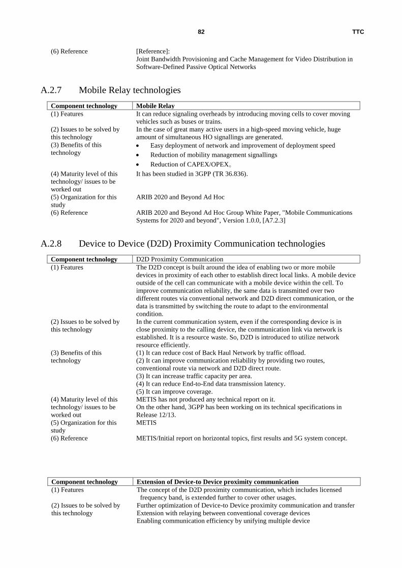
TTC 82
(6) Reference [Reference]:
Joint Bandwidth Provisioning and Cache Management for Video Distribution in
Software-Defined Passive Optical Networks
A.2.7 Mobile Relay technologies
Component technology Mobile Relay
(1) Features It can reduce signaling overheads by introducing moving cells to cover moving
vehicles such as buses or trains.
(2) Issues to be solved by
this technology
In the case of great many active users in a high-speed moving vehicle, huge
amount of simultaneous HO signallings are generated.
(3) Benefits of this
technology Easy deployment of network and improvement of deployment speed
Reduction of mobility management signallings
Reduction of CAPEX/OPEX。
(4) Maturity level of this
technology/ issues to be
worked out
It has been studied in 3GPP (TR 36.836).
(5) Organization for this
study
ARIB 2020 and Beyond Ad Hoc
(6) Reference ARIB 2020 and Beyond Ad Hoc Group White Paper, "Mobile Communications
Systems for 2020 and beyond", Version 1.0.0, [A7.2.3]
A.2.8 Device to Device (D2D) Proximity Communication technologies
Component technology D2D Proximity Communication
(1) Features The D2D concept is built around the idea of enabling two or more mobile
devices in proximity of each other to establish direct local links. A mobile device
outside of the cell can communicate with a mobile device within the cell. To
improve communication reliability, the same data is transmitted over two
different routes via conventional network and D2D direct communication, or the
data is transmitted by switching the route to adapt to the environmental
condition.
(2) Issues to be solved by
this technology
In the current communication system, even if the corresponding device is in
close proximity to the calling device, the communication link via network is
established. It is a resource waste. So, D2D is introduced to utilize network
resource efficiently.
(3) Benefits of this
technology
(1) It can reduce cost of Back Haul Network by traffic offload.
(2) It can improve communication reliability by providing two routes,
conventional route via network and D2D direct route.
(3) It can increase traffic capacity per area.
(4) It can reduce End-to-End data transmission latency.
(5) It can improve coverage.
(4) Maturity level of this
technology/ issues to be
worked out
METIS has not produced any technical report on it.
On the other hand, 3GPP has been working on its technical specifications in
Release 12/13.
(5) Organization for this
study
METIS
(6) Reference METIS/Initial report on horizontal topics, first results and 5G system concept.
Component technology Extension of Device-to Device proximity communication
(1) Features The concept of the D2D proximity communication, which includes licensed
frequency band, is extended further to cover other usages.
(2) Issues to be solved by
this technology
Further optimization of Device-to Device proximity communication and transfer
Extension with relaying between conventional coverage devices
Enabling communication efficiency by unifying multiple device

TTC 83
communications.
(3) Benefits of this
technology
It can be an optimum implementation scenario for radio resource.
It can be a communication means in the isolated area caused by neotwork
failure.
(4) Maturity level of this
technology/ issues to be
worked out
From the beginning of the 5G study, it has been studied as a main solution but
not an additional component.
(5) Organization for this
study
4G Americas
(6) Reference 4G Americas, 4G Americas' Recommendations on 5G Requirements and
Solutions, OCT 2014
Component technology Mesh Network
(1) Features It is a mesh network between devices. A part of traffic is transmitted over the
direct link between devices. The routing can be set up by SIPTO-like algorithm.
(2) Issues to be solved by
this technology
It is required to restore or extend network immediately for out of service area
due to disaster or failure.
(3) Benefits of this
technology
Easy network deployment, and faster deployment
(4) Maturity level of this
technology/ issues to be
worked out
Mesh network itself is an existing technology, but it has not been studied for
applying as a part of mobile system yet.
(5) Organization for this
study
ARIB 2020 and Beyond Ad Hoc
(6) Reference ARIB 2020 and Beyond Ad Hoc Group White Paper, “Mobile Communications
Systems for 2020 and beyond”, Version 1.0.0, [A7.2.2]
A.2.9 Coordination technology between Radio Access Technologies (RATs)
Component technology Unified management of multi-RATs by Single Radio Controller (SRC)
(1) Features Single Radio Controller (SRC) controls multiple RATs, and it controls multiple
RATs via the same single Core Network (CN) Interface.
(2) Issues to be solved by
this technology Efficient frequency spectrum utilization
QoE provisioning without RAT dependency
Enabling easy interoperability between RATs
Simplified network management
(3) Benefits of this
technology
It can easily perform traffic load distribution, and it can improve frequency
spectrum utilization and User Experience.
(4) Maturity level of this
technology/ issues to be
worked out
Still at the conceptual stage. It is assumed that C-RAN will be introduced.
(5) Organization for this
study
Wireless World Research Forum (WWRF)
(6) Reference WWRF
Outlook 9 (Multi-RAT Network Architecture)
Component technology Unified management of radio resources by Unified Radio Controller (URC)
(1) Features It can unify various heterogeneous Wireless Access methods such as 3G/4G,
WiFi. The Unified Radio Controller (URC) can control unified radio resources.
(2) Issues to be solved by
this technology
Since a single RAT has limited capacity for ever-increasing traffic from the
points of cost and frequency spectrum, existing RATs and other RATs such as
Wireless LAN, etc. should be utilized to complement lack of capacity.
(3) Benefits of this
technology
Improve traffic capacity by multi-band and multi RATs.
CAPEX/OPEX reduction by using the existing access methods。Improve QoE
by seamless Handover (HO) between heterogeneous networks
(4) Maturity level of this
technology/ issues to be
3GPP includes non-3GPP access accommodation, but further enhancement
toward 5G will be needed. It is FFS.

TTC 84
worked out
(5) Organization for this
study
ARIB 2020 and Beyond Ad Hoc
(6) Reference ARIB 2020 and Beyond Ad Hoc Group White Paper, "Mobile Communications
Systems for 2020 and beyond", Version 1.0.0, [A7.2.1] (Note) Although the above mentioned two technologies (SRC and URC) are defined in the different oraganizations, both concepts are similar.
There are some differences: URC is defined for radio resource control, on the other hand, SRC includes unification of CN interface.
Component technology Multi-RAT integration
(1) Features Seamless integration of different types of wireless systems
(2) Issues to be solved by
this technology Improve User Experience for 5G Use Cases
Improve operation efficiency for 5G Use Cases
(3) Benefits of this
technology
Guaranteeing service level and/or interference avoidance for coverage increase
and accommodating ever-growing number of customers
(4) Maturity level of this
technology/ issues to be
worked out
Extension of the current 3G/LTE-WiFi Integration
(5) Organization for this
study
4G Americas
(6) Reference 4G Americas, 4G Americas' Recommendations on 5G Requirements and
Solutions, OCT 2014
Component technology Mobile Backhaul access integration
(1) Features It can integrate Mobile Backhaul Radio and Access Radio from both aspects of
frequency and system.
(2) Issues to be solved
by this technology
It can mitigate inefficiency due to the division into Back-Haul Radio and
Access Radio, by coping with demand of increasing radio needs for Back
Haul links with extension of small cell utilizations.
(3) Benefits of this
technology
It can improve E2E performance and QoS by enhancing utilization efficiency of
system and radio.
(4) Maturity level of this
technology/ issues to be
worked out
It is for further investigation.
(5) Organization for this
study
4G Americas
(6) Reference 4G Americas, 4G Americas' Recommendations on 5G Requirements and
Solutions, OCT 2014
Component technology Coordination technologies between radio systems (Phantom Cell and WiFi)
(1) Features Multi-Domain Radio Resource Management (MD-RRM) can provide
information on user’s mobility with optimum system selection and service.
It can perform scheduling of radio resources for Cellular system and
Wireless LAN in real-time mode, based on information on user’s mobility
with optimum system selection and service, provided by MD-RRM.
(2) Issues to be solved by
this technology
To maximize utilization of limited radio resources for higher speed and higher
capacity.
(3) Benefits of this
technology
It enables to provide high throughput according to the traffic load to the Access
Points of Wireless LAN.
(4) Maturity level of this
technology/ issues to be
worked out
[At the maturity level]
It is still at the stage to confirm its efficiency by computer simulation in the
technical papers.
[Issues]
It should be confirmed its efficiency by the trial test.
(5) Organization for this
study
IEICE
(6) Reference NTT DOCOMO/ IEICE Technical Report RCS2013-237

TTC 85
A.2.10 Other radio technologies
Component technology URC (Ultra-Reliable Communication)
(1) Features It guarantees stable and reliable connectivity.
(2) Issues to be solved by
this technology
It can guarantee high reliability for connectivity and availability even under
severe conditions.
It needs to support the various connectivity requirements for the following
different communication-types:
Always connected communication-type like cloud computing with small
amount of data and low data speed or latency requirement
Latency critical communications such as V2V, V2X, etc.
(3) Benefits of this
technology
By solving the above mentioned issues, it can guarantee the following stable
connections:
Accommodating 10 - 100 times more number of connected devices than
now,
Prolonging device battery life 10 times more than now,
Reducing E2E latency to one-fifth of the present system.
(4) Maturity level of this
technology/ issues to be
worked out
Although actual solutions have not been described, it is mentioned that activities
at 3GPP (for example, Public Safety (R12)) or IEEE are quite limited.
(5) Organization for this
study
METIS
(6) Reference METIS/Deliverable D6.2 Initial report on horizontal topics, first results and 5G
system concept

TTC 86
Annex B Member list of the TTC Ad Hoc group on Future
Mobile Networking
Role Company/Organization Name
1 Leader NTT DOCOMO INC Takatoshi Okagawa
2 Sub-leader KDDI Corporation Michiaki Hayashi
3 Member NTC Corporation Koji Sato
4 Member NTT COMWARE CORPORATION Kei-ichi Sasaki
5 Member NTT DOCOMO INC Atsushi Minokuchi
6 Member Oki Electric Industry Co. Ltd. Masayuki Kashima
7 Member KDDI Corporation Atsushi Tagami
8 Member Akira Yamada
9 Member Cyber Creative Institute Co., Ltd. Kenji Nakanishi
10 Member SHARP Corporation Tetsuro Moriwaki
11 Member National Institute of Information and
Communications Technology (NICT)
Toshiaki Kuri
12 Member Nozomu Nishinaga
13 Member SOFTBANK Mobile Corp. Daisuke Yokota
14 Member NEC Corporation Takanori Iwai
15 Member Takashi Egawa
16 Member Kenji Obata
17 Member Toshiyuki Tamura
18 Member Hideo Himeno
19 Member NTT Hiroshi Ou
20 Member Jun-ichi Kani
21 Member Kenichi Kawamura
22 Member Arata Koike
23 Member Nokia Networks Japan Kiyohisa Wakabayashi
24 Member Hitachi Ltd. Yoshinori Ishikawa
25 Member Fujitsu Ltd. Shinichiro Aikawa
26 Member Ryuichi Takechi
27 Member Mitsubishi Electric Corp Masatoshi Katayama
28 Member Takashi Nishitani
29 Member Fumiki Hasegawa
30 Member Tetsushi Matsuda
31 Special Member University of Tokyo Akihiro Nakao
32 TTC Strategy
Committee Member
KDDI Corporation Masaaki Koga
33 TTC Strategy
Committee Member
NTT Kenichi Hiraki
34 TTC Strategy
Committee Member
Fujitsu Ltd. Mitsuhiro Azuma
35 TTC Secretariat TTC Masanori Goto
36 TTC Secretariat Koichi Onohara