TT-1434 4/06 - fireelectronics.com Literature/lit/tt1434.pdf · when disconnecting the battery....
20
TT-1434 4/06 INSTALLATION INSTRUCTIONS Original Issue Date: 3/06 Model: 20--150 kW Generator Sets, Northrop Grumman Market: Industrial Subject: Governor Service Kit GM38323 and Programming Kit GM39344 Introduction The digital isochronous governor programming kit includes the programming CD-ROM and cable for connecting the governor controller to the user’s PC. The programming kit or Parameter Setup Tool (PST) software tells the governor controller how to operate the generator set governing system for that application. Access and download the PST software by going to the following website: http://www.woodward.com/software/Download/ SWProductDetail.cfm?FileID=201 The digital isochronous governor kit replaces discontinued generator set governors. See Figure 1. Replacement governors are shipped unprogrammed. After installing and wiring the new governor service kit, download the PST software and follow the instructions to change the default settings. Service Kit Governor Assembly Replaces 324515 (DYN1-10784-000-1-12) GM38323 GM17644-4 (DPG-2101-002) 336236 (DYN1-10704-000-1-12) GM17644-3 (DPG-2104--xxx) Figure 1 Service Kits and Discontinued Governors The PST software overwrites any original programs in the governor controller’s nonvolatile memory. Make a backup copy of the files onto a disk and store the disk in a safe place. Read the entire procedure before beginning. Install the software onto a PC. Carefully follow these instructions and any additional instructions that appear on the screen during the download procedure. The instructions provided here assume you know how to operate a PC. Loading incorrect or incomplete files may cause permanent damage to the governor controller’s logic circuit board. Verify that the CD-ROM file contains settings for your specific generator set and engine. Do not attempt to modify the data files. Note: Some existing governor controllers do not require programming. Only governor controllers with a RJ11 connector (see Figure 2) need programming. GM17644-B SPEED DEC INC GAIN BAT+ BAT-- ACT ACT MPU--SHIELD MPU-- MPU+ COMM 1. Speed decrease 2. Speed increase 3. RJ11 connector 4. Gain potentiometer 1 2 3 4 Figure 2 Governor Controller Functions Before replacing the governor, verify that replacement is necessary by using Appendix D, Diagnostics and Troubleshooting.
Transcript of TT-1434 4/06 - fireelectronics.com Literature/lit/tt1434.pdf · when disconnecting the battery....

TT-1434 4/06
INSTALLATION INSTRUCTIONS
Original Issue Date: 3/06
Model: 20--150 kW Generator Sets, Northrop Grumman
Market: Industrial
Subject: Governor Service Kit GM38323 and Programming Kit GM39344
Introduction
The digital isochronous governor programming kit
includes the programming CD-ROM and cable for
connecting the governor controller to the user’s PC.
The programming kit or Parameter Setup Tool (PST)
software tells the governor controller how to operate the
generator set governing system for that application.
Access and download the PST software by going to the
following website:
http://www.woodward.com/software/Download/
SWProductDetail.cfm?FileID=201
The digital isochronous governor kit replaces
discontinued generator set governors. See Figure 1.
Replacement governors are shipped
unprogrammed. After installing and wiring the new
governor service kit, download the PST software and
follow the instructions to change the default settings.
Service Kit Governor Assembly Replaces
324515(DYN1-10784-000-1-12)
GM38323GM17644-4(DPG-2101-002)
336236(DYN1-10704-000-1-12)( )
GM17644-3(DPG-2104--xxx)
Figure 1 Service Kits and Discontinued Governors
The PST software overwrites any original programs in
the governor controller’s nonvolatile memory. Make a
backup copy of the files onto a disk and store the disk in
a safe place.
Read the entire procedure before beginning. Install the
software onto a PC. Carefully follow these instructions
and any additional instructions that appear on the screen
during the download procedure. The instructions
provided here assume you know how to operate a PC.
Loading incorrect or incomplete files may cause
permanent damage to the governor controller’s logic
circuit board. Verify that the CD-ROM file contains
settings for your specific generator set and engine. Do
not attempt to modify the data files.
Note: Some existing governor controllers do not require
programming. Only governor controllers with a
RJ11 connector (see Figure 2) need
programming.
GM17644-B
SPEED
DEC INC
GAIN
BAT+
BAT--
ACT
ACT
MPU--SHIELD
MPU--
MPU+
COMM
1. Speed decrease
2. Speed increase
3. RJ11 connector
4. Gain potentiometer
1 2
3
4
Figure 2 Governor Controller Functions
Before replacing the governor, verify that
replacement is necessary by using Appendix D,
Diagnostics and Troubleshooting.
2 TT-1434 4/06
Kit Components
� COMM port cable (9-pin RS-232 DB9F serial port
connector to a RJ11M plug)
� CD-ROM includes
� Parameter Text Files
� Governor Parameter Detail Form
� Governor Parameter Summary Form
� TT-1399 Governor Programming Instructions
� Woodward PST (parameter setup tool)
Features and Specifications
The microprocessor-based, digital isochronous
governor allows adjustment of set speed and gain.
Other adjustments include acceleration, deceleration,
ramp rates, idle speed set, and hold time. The COMM
port provides simple programming when connected to
the user’s PC. See Figure 2 for governor controller
illustration and Figure 3 for specifications.
Specifications Value
Maximum controlled output current 7 amps
Maximum current surge 14 amps for 10 seconds
Input signal from magnetic pickup 2.0 VAC RMS min. duringcranking
Ambient operating temperature --40�C to +85�C(--40�F to +185�F)
Environmental protection Oil, water, dust resistantvia conformal coating anddie cast enclosure
Electrical connections Euro-style terminal strip
Figure 3 Specifications
Other features include:
� 0.25% frequency control.
� Reverse battery protection.
� 9--30 VDC input.
� Smoke control on startup.
� Serial communication port.
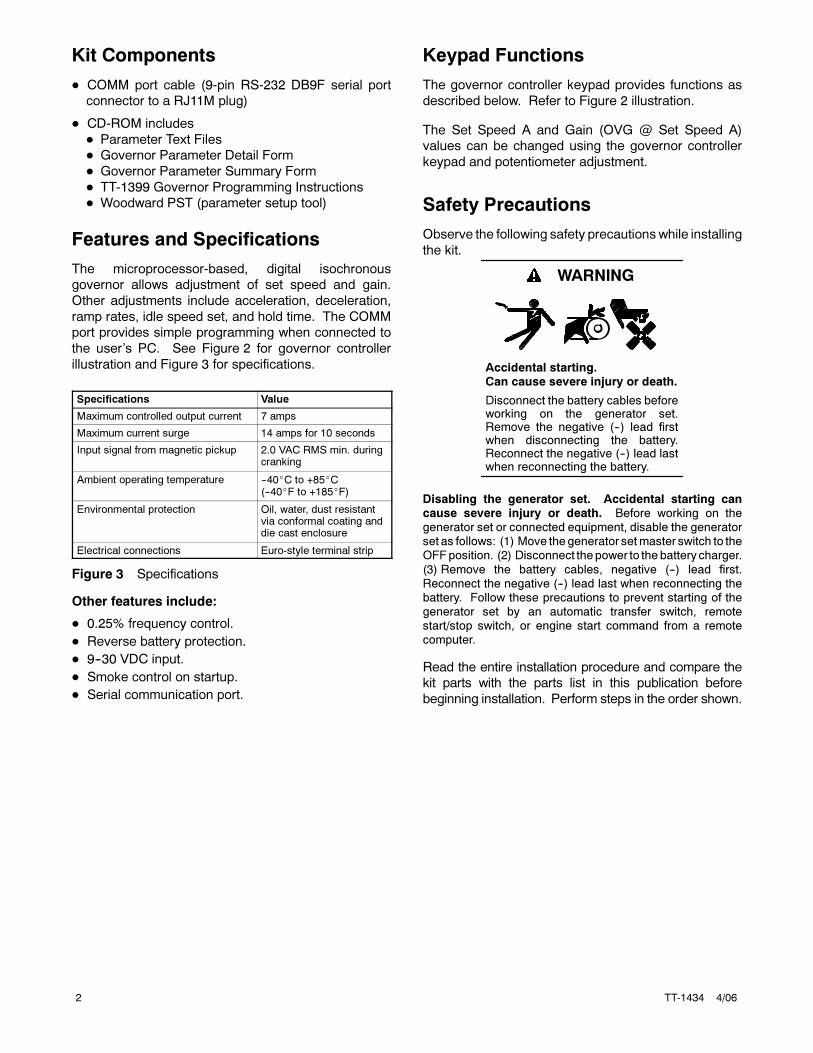
Keypad Functions
The governor controller keypad provides functions as
described below. Refer to Figure 2 illustration.
The Set Speed A and Gain (OVG @ Set Speed A)
values can be changed using the governor controller
keypad and potentiometer adjustment.
Safety Precautions
Observe the following safety precautionswhile installing
the kit.
Accidental starting.Can cause severe injury or death.
Disconnect the battery cables beforeworking on the generator set.Remove the negative (--) lead firstwhen disconnecting the battery.Reconnect the negative (--) lead lastwhen reconnecting the battery.
WARNING
Disabling the generator set. Accidental starting cancause severe injury or death. Before working on thegenerator set or connected equipment, disable the generatorset as follows: (1) Move thegenerator setmaster switch to theOFFposition. (2) Disconnect thepower to thebattery charger.
(3) Remove the battery cables, negative (--) lead first.Reconnect the negative (--) lead last when reconnecting thebattery. Follow these precautions to prevent starting of thegenerator set by an automatic transfer switch, remotestart/stop switch, or engine start command from a remotecomputer.
Read the entire installation procedure and compare the
kit parts with the parts list in this publication before
beginning installation. Perform steps in the order shown.
TT-1434 4/06 3
Special Equipment Needed� Load bank sized at 25% of the generator set standby
rating (minimum).
1 Hardware Installation Procedure
1.1 Remove the generator set from service.
1.1.1 Place the generator setmaster switch in theOFF/RESET position.
1.1.2 Disconnect the power to the battery charger, if
equipped.
1.1.3 Disconnect the generator set engine startingbattery(ies), negative (--) lead first.
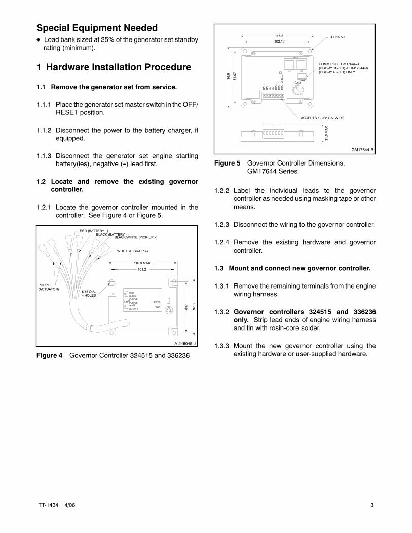
1.2 Locate and remove the existing governorcontroller.
1.2.1 Locate the governor controller mounted in the
controller. See Figure 4 or Figure 5.
A-246045-J
RED (BATTERY +)BLACK (BATTERY --)
BLACK/WHITE (PICK-UP --)
WHITE (PICK-UP +)
PURPLE(ACTUATOR)
5.56 DIA.4 HOLES
116.3 MAX.
103.2
84.1
97.3
RED
BLACK
PURPLE
wHITE
ACT
+
SPEED
--
PURPLE
BLK/WHI--
~
GAIN
Figure 4 Governor Controller 324515 and 336236
GM17644-B
SPEED
DEC INC
GAIN
BAT+
BAT--
ACT
ACT
MPU--SHIELD
MPU--
MPU+
96.8
115.8
84.07
103.12
31.0
MAX
ACCEPTS 12--22 GA. WIRE
4X 5.59
COMM
COMM PORT GM17644--4
(DGP--2101--001) & GM17644--6
(DGP--2146--001) ONLY
Figure 5 Governor Controller Dimensions,
GM17644 Series
1.2.2 Label the individual leads to the governor
controller as needed using masking tape or other
means.
1.2.3 Disconnect the wiring to the governor controller.
1.2.4 Remove the existing hardware and governor
controller.
1.3 Mount and connect new governor controller.
1.3.1 Remove the remaining terminals from the engine
wiring harness.
1.3.2 Governor controllers 324515 and 336236
only. Strip lead ends of engine wiring harness
and tin with rosin-core solder.
1.3.3 Mount the new governor controller using the
existing hardware or user-supplied hardware.
4 TT-1434 4/06
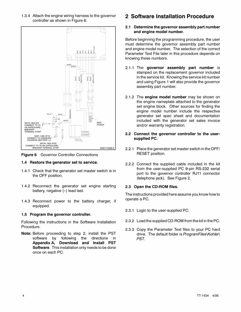
1.3.4 Attach the engine wiring harness to the governor
controller as shown in Figure 6.
GM17725B-E
SW7N--1624--9722
BLACK
CONNECT TO 7N ON SAFEGUARDBREAKER TERMINAL STRIP
SWP--1450--5716CONNECT TO CRANKINGSOLENOID (BATTERY (+)
70
P7N
RELAY WHITE
ACTUATOR
BLACK
UNINSULATED
WHITE
UNINSULATED
BLACK
WHITE
MPU--
MPU--SHLD
ACT--
ACT+
BAT--
BAT+
MPU+
UNIN
SULATED
WHITE
BLACK
86 85
87A
87K5
NO
NC
30
C
SW70-1624-572CONNECT TO 70ON SAFEGUARDBREAKERTERMINAL STRIP
MAGPICKUP
Figure 6 Governor Controller Connections
1.4 Restore the generator set to service.
1.4.1 Check that the generator set master switch is in
the OFF position.
1.4.2 Reconnect the generator set engine starting
battery, negative (--) lead last.
1.4.3 Reconnect power to the battery charger, if
equipped.
1.5 Program the governor controller.
Following the instructions in the Software Installation
Procedure.
Note: Before proceeding to step 2, install the PST
software by following the directions in
Appendix A, Download and Install PST
Software. This installation only needs to be done
once on each PC.
2 Software Installation Procedure
2.1 Determine the governor assembly part number
and engine model number.
Before beginning the programming procedure, the user
must determine the governor assembly part number
and engine model number. The selection of the correct
Parameter Text File later in this procedure depends on
knowing these numbers.
2.1.1 The governor assembly part number is
stamped on the replacement governor included
in the service kit. Knowing the service kit number
and using Figure 1 will also provide the governor
assembly part number.
2.1.2 The engine model number may be shown on
the engine nameplate attached to the generator
set engine block. Other sources for finding the
engine model number include the respective
generator set spec sheet and documentation
included with the generator set sales invoice
and/or warranty registration.
2.2 Connect the governor controller to the user-supplied PC.
2.2.1 Place the generator setmaster switch in theOFF/
RESET position.
2.2.2 Connect the supplied cable included in the kit
from the user-supplied PC 9-pin RS-232 serial
port to the governor controller RJ11 connector
(telephone jack). See Figure 2.
2.3 Open the CD-ROM files.
The instructions provided here assume you know how to
operate a PC.
2.3.1 Login to the user-supplied PC.
2.3.2 Load the suppliedCD-ROM from the kit in thePC.
2.3.3 Copy the Parameter Text files to your PC hard
drive. The default folder is ProgramFiles\Kohler\
PST.

TT-1434 4/06 5
2.3.4 Energize the governor controller by moving the
white lead/70A from the normally open K5
contact to the normally closed K5 contact. See
Figure 7. Connecting to the normally closed
contact will energize the governor controller
without starting/ running the generator set.
GM17725B-E
SW70--1624--5722
SW7N--1624--9722
CONNECT TO 70 ON SAFEGUARDBREAKER TERMINAL STRIP
BLACK
CONNECT TO 7N ON SAFEGUARDBREAKER TERMINAL STRIP
SWP--1450--5716CONNECT TO CRANKINGSOLENOID (BATTERY (+)
70
P7N
RELAY
WHITE
ACTUATOR
MAG PICK--UP
BLACK
UNINSULATED
WHITE
UNINSULATED
BLACK
WHITE
MPU--
MPU--SHLD
ACT--
ACT+
BAT--
BAT+
MPU+
UNIN
SULATED
WHITE
BLACK
86 85
87A
87K5
NO
NC
30
C
1. Normally closed K5 contact
2. Normally open K5 contact3. White lead/70A
1
2 3
Figure 7 Energizing Governor Controller
2.3.5 See Appendix B, Parameter Definitions, for
detailed explanations of each parameter and
Appendix C, Parameter Defaults Reference.
2.4 Program the governor controller and save thefiles.
2.4.1 Double click on PST icon to start programming
software.
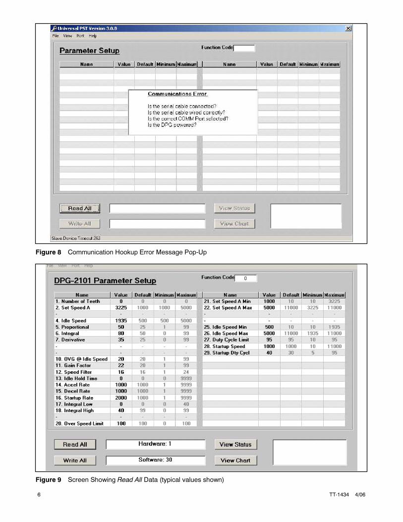
If you get an error message as shown in Figure 8,
verify the cable connection. It may also be
necessary to use the Port menu to choose a
different communication port depending on the
configuration or the laptop.
2.4.2 Use the part number data determined in step 1
and select the Parameter Text file by clicking
File--Open--“?.Txt”.
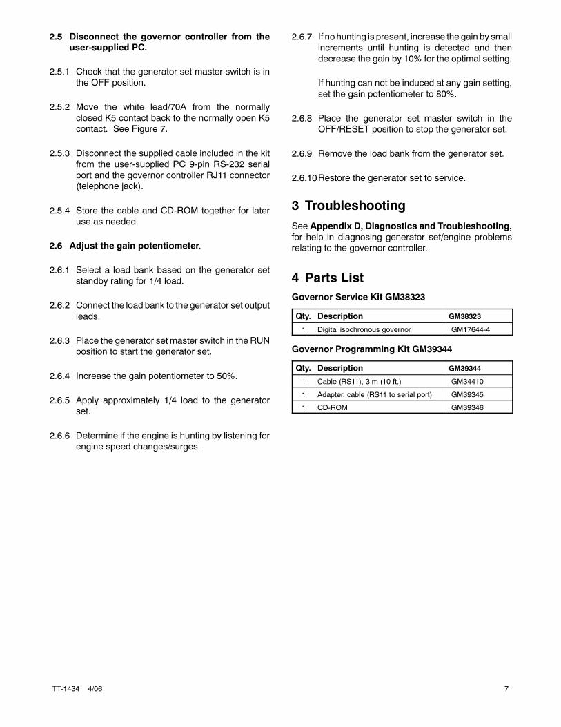
The Read All values on the PC screen (see
Figure 9) are the values shown on the printed
Parameter Summary form.
2.4.3 ClickWrite All. The selected parameter text file is
then sent to the governor controller. Wait until
download is complete when the Write All button
reappears.
2.4.4 Close the PST software.
6 TT-1434 4/06
Figure 8 Communication Hookup Error Message Pop-Up
Figure 9 Screen Showing Read All Data (typical values shown)
TT-1434 4/06 7
2.5 Disconnect the governor controller from theuser-supplied PC.
2.5.1 Check that the generator set master switch is in
the OFF position.
2.5.2 Move the white lead/70A from the normally
closed K5 contact back to the normally open K5
contact. See Figure 7.
2.5.3 Disconnect the supplied cable included in the kit
from the user-supplied PC 9-pin RS-232 serial
port and the governor controller RJ11 connector
(telephone jack).
2.5.4 Store the cable and CD-ROM together for later
use as needed.
2.6 Adjust the gain potentiometer.
2.6.1 Select a load bank based on the generator set
standby rating for 1/4 load.
2.6.2 Connect the load bank to the generator set output
leads.
2.6.3 Place the generator set master switch in the RUN
position to start the generator set.
2.6.4 Increase the gain potentiometer to 50%.
2.6.5 Apply approximately 1/4 load to the generator
set.
2.6.6 Determine if the engine is hunting by listening for
engine speed changes/surges.
2.6.7 If no hunting is present, increase the gain by small
increments until hunting is detected and then
decrease the gain by 10% for the optimal setting.
If hunting can not be induced at any gain setting,
set the gain potentiometer to 80%.
2.6.8 Place the generator set master switch in the
OFF/RESET position to stop the generator set.
2.6.9 Remove the load bank from the generator set.
2.6.10Restore the generator set to service.
3 Troubleshooting
See Appendix D, Diagnostics and Troubleshooting,
for help in diagnosing generator set/engine problems
relating to the governor controller.
4 Parts List
Governor Service Kit GM38323
Qty. Description GM38323
1 Digital isochronous governor GM17644-4
Governor Programming Kit GM39344
Qty. Description GM39344
1 Cable (RS11), 3 m (10 ft.) GM34410
1 Adapter, cable (RS11 to serial port) GM39345
1 CD-ROM GM39346
8 TT-1434 4/06
Appendix A PST Software
The PST software enables the user to adjust parameter
settings and monitor governor operation when a user-
supplied PC is connected to the governor controller via
the COMM port. Access and download the PST
software using the website shown on page 1.
Features
� Automatic configuration to each generator set when
communication is established.
� Read/write access to all of a generator set’s
programmable parameters and features.
� Display of each parameter’s default, minimum, and
maximum values.
� Diagnostics utilizing automatic refresh of the
generator set’s status.
� Saving and reloading generator set setup information
to and from a file for reuse.
� Single button read for acquiring current parameter
values.
� Single button write to program a generator set with
previously saved setup values.
� Engine speedmonitoring via a chart recorder to aid in
governor tuning.
� Saving chart recorder data to a Microsoft� Excel
compatible file.
� Help information on each of the governor’s
parameters.
� Help information on using the PST software.
PC System Requirements
� 100% IBM� PC compatible with a 133 MHz or higher
Pentium� compatible CPU.
� Microsoft Windows� 98SE (second edition),
Windows NT� Workstation Version 4.0, Windows�
2000, or Windows XP� operating system.
� Display resolution with SVGA (800 x 600) or higher.
� CD-ROM drive and minimum of 4 MB hard drive
space for installation.
� One 9-pin RS-232 DB9M serial port.
� PCs using USB ports will require a serial adapter.
� Stable power supply. A laptop system with a fully
charged battery or desktop system running with a
battery backup system is recommended.
PST Software User Interface Overview
ThePST software for generator set applications has two
main displaymodes—Table View andChart View. Table
view is the PST software default setting.
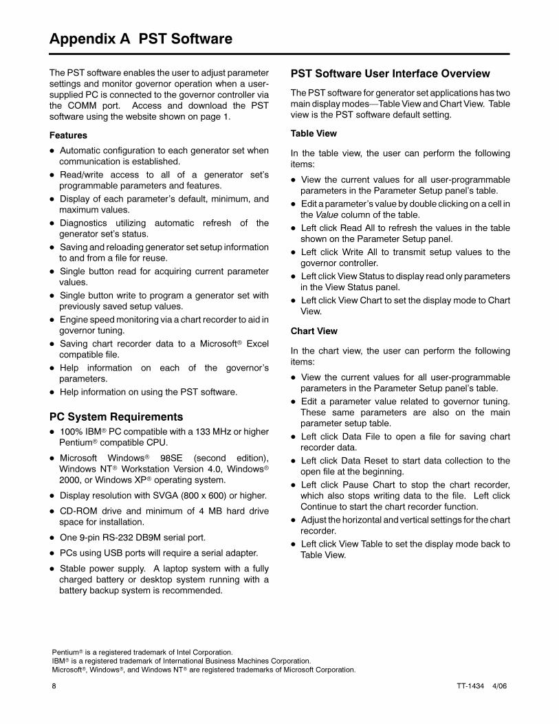
Table View
In the table view, the user can perform the following
items:
� View the current values for all user-programmable
parameters in the Parameter Setup panel’s table.
� Edit a parameter’s value by double clicking on a cell in
the Value column of the table.
� Left click Read All to refresh the values in the table
shown on the Parameter Setup panel.
� Left click Write All to transmit setup values to the
governor controller.
� Left click View Status to display read only parameters
in the View Status panel.
� Left click View Chart to set the display mode to Chart
View.
Chart View
In the chart view, the user can perform the following
items:
� View the current values for all user-programmable
parameters in the Parameter Setup panel’s table.
� Edit a parameter value related to governor tuning.
These same parameters are also on the main
parameter setup table.
� Left click Data File to open a file for saving chart
recorder data.
� Left click Data Reset to start data collection to the
open file at the beginning.
� Left click Pause Chart to stop the chart recorder,
which also stops writing data to the file. Left click
Continue to start the chart recorder function.
� Adjust the horizontal and vertical settings for the chart
recorder.
� Left click View Table to set the display mode back to
Table View.
Pentium� is a registered trademark of Intel Corporation.IBM� is a registered trademark of International Business Machines Corporation.
Microsoft�, Windows�, and Windows NT� are registered trademarks of Microsoft Corporation.
TT-1434 4/06 9
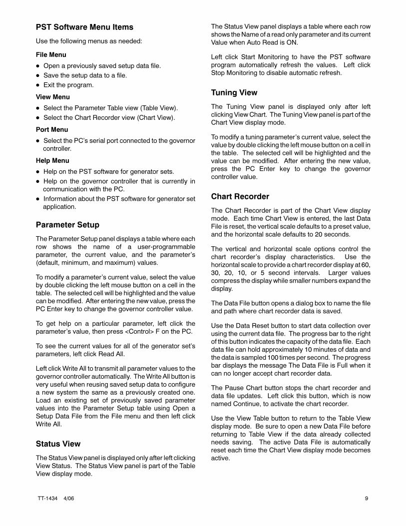
PST Software Menu Items
Use the following menus as needed:
File Menu
� Open a previously saved setup data file.
� Save the setup data to a file.
� Exit the program.
View Menu
� Select the Parameter Table view (Table View).
� Select the Chart Recorder view (Chart View).
Port Menu
� Select the PC’s serial port connected to the governor
controller.
Help Menu
� Help on the PST software for generator sets.
� Help on the governor controller that is currently in
communication with the PC.
� Information about the PST software for generator set
application.
Parameter Setup
TheParameter Setup panel displays a table where each
row shows the name of a user-programmable
parameter, the current value, and the parameter’s
(default, minimum, and maximum) values.
To modify a parameter’s current value, select the value
by double clicking the left mouse button on a cell in the
table. The selected cell will be highlighted and the value
can bemodified. After entering the new value, press the
PC Enter key to change the governor controller value.
To get help on a particular parameter, left click the
parameter’s value, then press <Control> F on the PC.
To see the current values for all of the generator set’s
parameters, left click Read All.
Left clickWrite All to transmit all parameter values to the
governor controller automatically. TheWrite All button is
very useful when reusing saved setup data to configure
a new system the same as a previously created one.
Load an existing set of previously saved parameter
values into the Parameter Setup table using Open a
Setup Data File from the File menu and then left click
Write All.
Status View
TheStatus View panel is displayed only after left clicking
View Status. The Status View panel is part of the Table
View display mode.
The Status View panel displays a table where each row
shows theNameof a read only parameter and its current
Value when Auto Read is ON.
Left click Start Monitoring to have the PST software
program automatically refresh the values. Left click
Stop Monitoring to disable automatic refresh.
Tuning View
The Tuning View panel is displayed only after left
clicking ViewChart. The Tuning View panel is part of the
Chart View display mode.
To modify a tuning parameter’s current value, select the
value by double clicking the left mouse button on a cell in
the table. The selected cell will be highlighted and the
value can be modified. After entering the new value,
press the PC Enter key to change the governor
controller value.
Chart Recorder
The Chart Recorder is part of the Chart View display
mode. Each time Chart View is entered, the last Data
File is reset, the vertical scale defaults to a preset value,
and the horizontal scale defaults to 20 seconds.
The vertical and horizontal scale options control the
chart recorder’s display characteristics. Use the
horizontal scale to provide a chart recorder display at 60,
30, 20, 10, or 5 second intervals. Larger values
compress the displaywhile smaller numbers expand the
display.
The Data File button opens a dialog box to name the file
and path where chart recorder data is saved.
Use the Data Reset button to start data collection over
using the current data file. The progress bar to the right
of this button indicates the capacity of the data file. Each
data file can hold approximately 10 minutes of data and
the data is sampled 100 times per second. Theprogress
bar displays the message The Data File is Full when it
can no longer accept chart recorder data.
The Pause Chart button stops the chart recorder and
data file updates. Left click this button, which is now
named Continue, to activate the chart recorder.
Use the View Table button to return to the Table View
display mode. Be sure to open a new Data File before
returning to Table View if the data already collected
needs saving. The active Data File is automatically
reset each time the Chart View display mode becomes
active.

10 TT-1434 4/06
Download and Install PST Software
Before going to the generator set jobsite, It is
recommended to access and download the PST
software to your PC hard drive where a Internet
connection is available.
The instructions provided here assume you know how to
operate a PC.
1. Login to the user-supplied PC.
2. Login to the Internet.
3. Access the website shown on page 1 and click
download.
4. Click new registration, complete the registration
information, and then click register.
5. The website will start the PST software download
which is about 25 MB.
6. Copy the PST software files to a designated folder
on your PC hard drive.
7. Log off the Internet.
8. Unzip the files to a designated folder on your PC
hard drive.
9. Open the readme.txt file and review the contents.
10. Run the setup.exe file. Use the readme.txt file as
needed.
11. Follow the prompts as directed.
TT-1434 4/06 11
Appendix B Parameter Definitions
Use this appendix for definitions of each of the
calibration values. Appendix C, Parameter Default
Settings, lists the default settings.
When changing values using the keypad, the PST
software display on the user’s PC will not automatically
update. To refresh the PST software display, the user
must select a different parameter with the PC mouse
and then go back to the desired value. The PST
software provides Read All button that will refresh all of
the parameter values.
1. Number of Flywheel Teeth. Enter the value from
the Governor Parameter Summary. This display is
not required. Displayed speeds can be changed
between Hz and rpm.
2. Set Speed A. Enter the value from the Governor
Parameter Summary.
3. Parameter not used.
4. Idle Speed. Enter the value from the Governor
Parameter Summary.
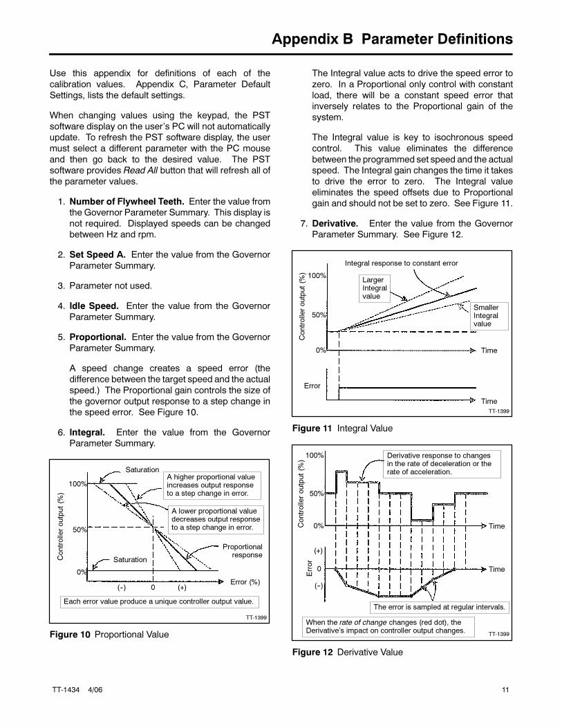
5. Proportional. Enter the value from the Governor
Parameter Summary.
A speed change creates a speed error (the
difference between the target speed and the actual
speed.) The Proportional gain controls the size of
the governor output response to a step change in
the speed error. See Figure 10.
6. Integral. Enter the value from the Governor
Parameter Summary.
TT-1399
Saturation
Each error value produce a unique controller output value.
A higher proportional valueincreases output responseto a step change in error.
A lower proportional valuedecreases output responseto a step change in error.
Proportionalresponse
0%
50%
100%
SaturationControlleroutput(%
)
(--) (+)0Error (%)
Figure 10 Proportional Value
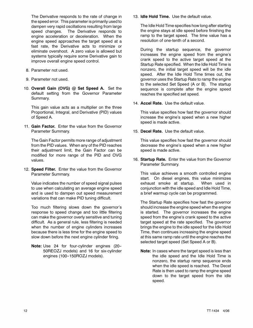
The Integral value acts to drive the speed error to
zero. In a Proportional only control with constant
load, there will be a constant speed error that
inversely relates to the Proportional gain of the
system.
The Integral value is key to isochronous speed
control. This value eliminates the difference
between the programmed set speed and the actual
speed. The Integral gain changes the time it takes
to drive the error to zero. The Integral value
eliminates the speed offsets due to Proportional
gain and should not be set to zero. See Figure 11.
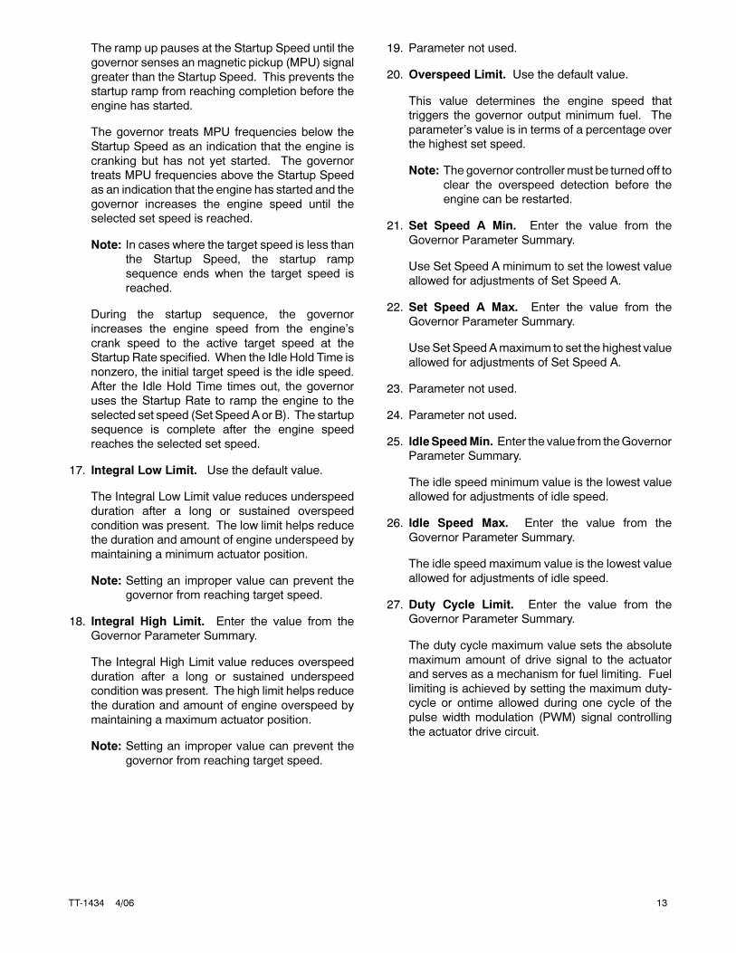
7. Derivative. Enter the value from the Governor
Parameter Summary. See Figure 12.
TT-1399
LargerIntegralvalue
SmallerIntegralvalue
Controlleroutput(%
)
Time
Error
0%
50%
100%
Time
Integral response to constant error
Figure 11 Integral Value
TT-1399
Derivative response to changesin the rate of deceleration or therate of acceleration.
When the rate of change changes (red dot), theDerivative’s impact on controller output changes.
The error is sampled at regular intervals.
Controlleroutput(%
)
Time
Error
(--)
(+)
0
0%
50%
100%
Time
Figure 12 Derivative Value
12 TT-1434 4/06
The Derivative responds to the rate of change in
the speed error. This parameter is primarily used to
dampen very rapid oscillations resulting from large
speed changes. The Derivative responds to
engine acceleration or deceleration. When the
engine speed approaches the target speed at a
fast rate, the Derivative acts to minimize or
eliminate overshoot. A zero value is allowed but
systems typically require some Derivative gain to
improve overall engine speed control.
8. Parameter not used.
9. Parameter not used.
10. Overall Gain (OVG) @ Set Speed A. Set the
default setting from the Governor Parameter
Summary.
This gain value acts as a multiplier on the three
Proportional, Integral, and Derivative (PID) values
of Speed A.
11. Gain Factor. Enter the value from the Governor
Parameter Summary.
The Gain Factor permits more range of adjustment
from the PID values. When any of the PID reaches
their adjustment limit, the Gain Factor can be
modified for more range of the PID and OVG
values.
12. Speed Filter. Enter the value from the Governor
Parameter Summary.
Value indicates the number of speed signal pulses
to use when calculating an average engine speed
and is used to dampen out speed measurement
variations that can make PID tuning difficult.
Too much filtering slows down the governor’s
response to speed change and too little filtering
can make the governor overly sensitive and tuning
difficult. As a general rule, less filtering is needed
when the number of engine cylinders increases
because there is less time for the engine speed to
slow down before the next engine cylinder firing.
Note: Use 24 for four-cylinder engines (20--
50REOZJ models) and 16 for six-cylinder
engines (100--150ROZJ models).
13. Idle Hold Time. Use the default value.
The Idle Hold Time specifies how long after starting
the engine stays at idle speed before finishing the
ramp to the target speed. The time value has a
resolution of one-tenth of a second.
During the startup sequence, the governor
increases the engine speed from the engine’s
crank speed to the active target speed at the
Startup Rate specified. When the Idle Hold Time is
nonzero, the initial target speed will be the idle
speed. After the Idle Hold Time times out, the
governor uses the Startup Rate to ramp the engine
to the selected Set Speed (A or B). The startup
sequence is complete after the engine speed
reaches the specified set speed.
14. Accel Rate. Use the default value.
This value specifies how fast the governor should
increase the engine’s speed when a new higher
speed is made active.
15. Decel Rate. Use the default value.
This value specifies how fast the governor should
decrease the engine’s speed when a new higher
speed is made active.
16. Startup Rate. Enter the value from the Governor
Parameter Summary.
This value achieves a smooth controlled engine
start. On diesel engines, this value minimizes
exhaust smoke at startup. When used in
conjunction with the idle speed and Idle Hold Time,
a brief warmup cycle can be programmed.
The Startup Rate specifies how fast the governor
should increase the engine speed when the engine
is started. The governor increases the engine
speed from the engine’s crank speed to the active
target speed at the rate specified. The governor
brings the engine to the idle speed for the Idle Hold
Time, then continues increasing the engine speed
at this same ramp rate until the engine reaches the
selected target speed (Set Speed A or B).
Note: In cases where the target speed is less than
the idle speed and the Idle Hold Time is
nonzero, the startup ramp sequence ends
when the idle speed is reached. The Decel
Rate is then used to ramp the engine speed
down to the target speed from the idle
speed.
TT-1434 4/06 13
The ramp up pauses at the Startup Speed until the
governor senses an magnetic pickup (MPU) signal
greater than the Startup Speed. This prevents the
startup ramp from reaching completion before the
engine has started.
The governor treats MPU frequencies below the
Startup Speed as an indication that the engine is
cranking but has not yet started. The governor
treats MPU frequencies above the Startup Speed
as an indication that the engine has started and the
governor increases the engine speed until the
selected set speed is reached.
Note: In cases where the target speed is less than
the Startup Speed, the startup ramp
sequence ends when the target speed is
reached.
During the startup sequence, the governor
increases the engine speed from the engine’s
crank speed to the active target speed at the
Startup Rate specified. When the Idle Hold Time is
nonzero, the initial target speed is the idle speed.
After the Idle Hold Time times out, the governor
uses the Startup Rate to ramp the engine to the
selected set speed (Set SpeedA or B). The startup
sequence is complete after the engine speed
reaches the selected set speed.
17. Integral Low Limit. Use the default value.
The Integral Low Limit value reduces underspeed
duration after a long or sustained overspeed
condition was present. The low limit helps reduce
the duration and amount of engine underspeed by
maintaining a minimum actuator position.
Note: Setting an improper value can prevent the
governor from reaching target speed.
18. Integral High Limit. Enter the value from the
Governor Parameter Summary.
The Integral High Limit value reduces overspeed
duration after a long or sustained underspeed
condition was present. The high limit helps reduce
the duration and amount of engine overspeed by
maintaining a maximum actuator position.
Note: Setting an improper value can prevent the
governor from reaching target speed.
19. Parameter not used.
20. Overspeed Limit. Use the default value.
This value determines the engine speed that
triggers the governor output minimum fuel. The
parameter’s value is in terms of a percentage over
the highest set speed.
Note: The governor controllermust be turned off to
clear the overspeed detection before the
engine can be restarted.
21. Set Speed A Min. Enter the value from the
Governor Parameter Summary.
Use Set Speed A minimum to set the lowest value
allowed for adjustments of Set Speed A.
22. Set Speed A Max. Enter the value from the
Governor Parameter Summary.
UseSet SpeedAmaximum to set the highest value
allowed for adjustments of Set Speed A.
23. Parameter not used.
24. Parameter not used.
25. Idle SpeedMin. Enter the value from theGovernor
Parameter Summary.
The idle speed minimum value is the lowest value
allowed for adjustments of idle speed.
26. Idle Speed Max. Enter the value from the
Governor Parameter Summary.
The idle speed maximum value is the lowest value
allowed for adjustments of idle speed.
27. Duty Cycle Limit. Enter the value from the
Governor Parameter Summary.
The duty cycle maximum value sets the absolute
maximum amount of drive signal to the actuator
and serves as a mechanism for fuel limiting. Fuel
limiting is achieved by setting the maximum duty-
cycle or ontime allowed during one cycle of the
pulse width modulation (PWM) signal controlling
the actuator drive circuit.
14 TT-1434 4/06
28. Startup Speed. Use the default value.
The Startup Speed value allows the governor to
determine whether the engine is cranking or
running whenever an engine speed signal is
present.
The Startup Speed value should be at least 10%
higher that the fastest engine cranking speed but
lower than the engine’s idle speed.
If the Startup Speed is too low (less than crank
speed) the governor’s target speed is ramped to
the active Set Speed (Idle, Set Speed A or B)
before the engine has started. When the engine
does not start, it may overspeed or output
excessive smoke because the startup ramp,
having already completed, no longer controls the
rate of engine speed increase.
If the Startup Speed is too high (above the active
set speed) then the Startup Speed becomes the
target speed that the governor must reach before
the governor considers the startup sequence
complete. Typically, the startup sequence ends
when the engine speed reaches the active set
speed. The active set speed is the idle speed if the
Idle Hold Time parameter is a nonzero value or the
selected set speed (either Set Speed A or B).
29. Startup Duty Cycle. Enter the value from the
Governor Parameter Summary.
The StartupDuty Cycle value is used to preload the
PID values with a PWM duty cycle value that
provides an actuator output signal sufficient to
allow enough fuel to idle the engine.
If the Startup Duty Cycle value is too low, the
engine crank time may be longer than desired
because the governor’s actuator output starts from
a value much smaller than needed to begin
opening the fuel valve.
If the Startup Duty Cycle value is too high, the
engine may overspeed because the actuator
opens more that needed to start the engine.
TT-1434 4/06 15
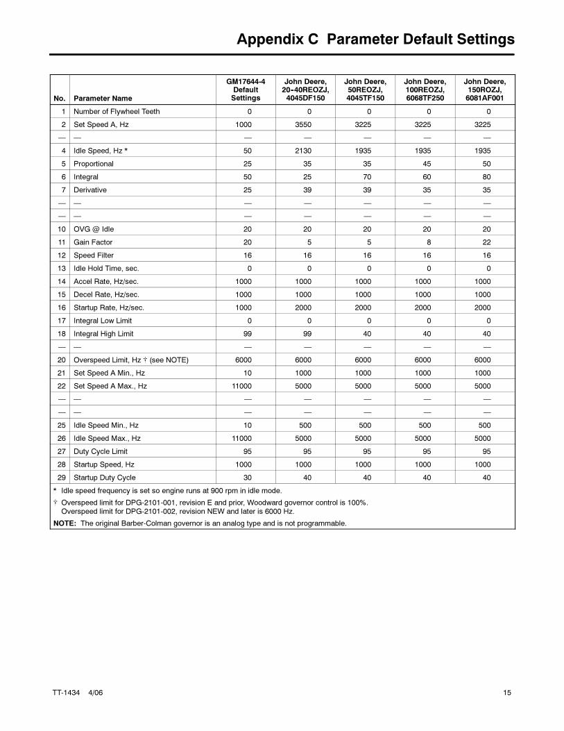
Appendix C Parameter Default Settings
No. Parameter Name
GM17644-4DefaultSettings
John Deere,20--40REOZJ,4045DF150
John Deere,50REOZJ,4045TF150
John Deere,100REOZJ,6068TF250
John Deere,150ROZJ,6081AF001
1 Number of Flywheel Teeth 0 0 0 0 0
2 Set Speed A, Hz 1000 3550 3225 3225 3225
— — — — — — —
4 Idle Speed, Hz * 50 2130 1935 1935 1935
5 Proportional 25 35 35 45 50
6 Integral 50 25 70 60 80
7 Derivative 25 39 39 35 35
— — — — — — —
— — — — — — —
10 OVG @ Idle 20 20 20 20 20
11 Gain Factor 20 5 5 8 22
12 Speed Filter 16 16 16 16 16
13 Idle Hold Time, sec. 0 0 0 0 0
14 Accel Rate, Hz/sec. 1000 1000 1000 1000 1000
15 Decel Rate, Hz/sec. 1000 1000 1000 1000 1000
16 Startup Rate, Hz/sec. 1000 2000 2000 2000 2000
17 Integral Low Limit 0 0 0 0 0
18 Integral High Limit 99 99 40 40 40
— — — — — — —
20 Overspeed Limit, Hz � (see NOTE) 6000 6000 6000 6000 6000
21 Set Speed A Min., Hz 10 1000 1000 1000 1000
22 Set Speed A Max., Hz 11000 5000 5000 5000 5000
— — — — — — —
— — — — — — —
25 Idle Speed Min., Hz 10 500 500 500 500
26 Idle Speed Max., Hz 11000 5000 5000 5000 5000
27 Duty Cycle Limit 95 95 95 95 95
28 Startup Speed, Hz 1000 1000 1000 1000 1000
29 Startup Duty Cycle 30 40 40 40 40
* Idle speed frequency is set so engine runs at 900 rpm in idle mode.
� Overspeed limit for DPG-2101-001, revision E and prior, Woodward governor control is 100%.Overspeed limit for DPG-2101-002, revision NEW and later is 6000 Hz.
NOTE: The original Barber-Colman governor is an analog type and is not programmable.
16 TT-1434 4/06
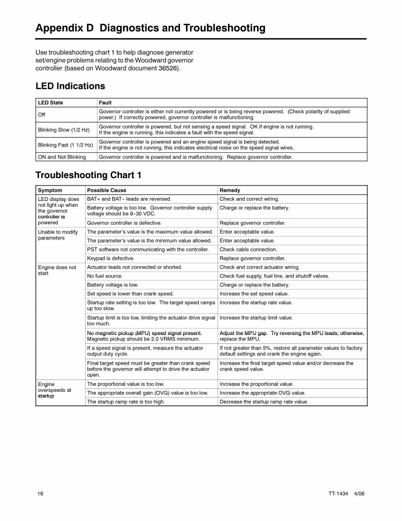
Appendix D Diagnostics and Troubleshooting
Use troubleshooting chart 1 to help diagnose generator
set/engine problems relating to theWoodward governor
controller (based on Woodward document 36526).
LED Indications
LED State Fault
OffGovernor controller is either not currently powered or is being reverse powered. (Check polarity of suppliedpower.) If correctly powered, governor controller is malfunctioning.
Blinking Slow (1/2 Hz)Governor controller is powered, but not sensing a speed signal. OK if engine is not running.If the engine is running, this indicates a fault with the speed signal.
Blinking Fast (1 1/2 Hz)Governor controller is powered and an engine speed signal is being detected.If the engine is not running, this indicates electrical noise on the speed signal wires.
ON and Not Blinking Governor controller is powered and is malfunctioning. Replace governor controller.
Troubleshooting Chart 1
Symptom Possible Cause Remedy
LED display doesli h h
BAT+ and BAT-- leads are reversed. Check and correct wiring.p ynot light up whenthe governorcontroller is
Battery voltage is too low. Governor controller supplyvoltage should be 9--30 VDC.
Charge or replace the battery.
controller ispowered Governor controller is defective. Replace governor controller.
Unable to modify The parameter’s value is the maximum value allowed. Enter acceptable value.yparameters
The parameter’s value is the minimum value allowed. Enter acceptable value.
PST software not communicating with the controller. Check cable connection.
Keypad is defective. Replace governor controller.
Engine does not Actuator leads not connected or shorted. Check and correct actuator wiring.gstart
No fuel source. Check fuel supply, fuel line, and shutoff valves.
Battery voltage is low. Charge or replace the battery.
Set speed is lower than crank speed. Increase the set speed value.
Startup rate setting is too low. The target speed rampsup too slow.
Increase the startup rate value.
Startup limit is too low, limiting the actuator drive signaltoo much.
Increase the startup limit value.
No magnetic pickup (MPU) speed signal present. Adjust the MPU gap. Try reversing the MPU leads; otherwise,No magnetic pickup (MPU) speed signal present.Magnetic pickup should be 2.0 VRMS minimum.
Adjust the MPU gap. Try reversing the MPU leads; otherwise,replace the MPU.
If a speed signal is present, measure the actuatoroutput duty cycle.
If not greater than 5%, restore all parameter values to factorydefault settings and crank the engine again.
Final target speed must be greater than crank speedbefore the governor will attempt to drive the actuatoropen.
Increase the final target speed value and/or decrease thecrank speed value.
Engined
The proportional value is too low. Increase the proportional value.goverspeeds atstartup
The appropriate overall gain (OVG) value is too low. Increase the appropriate OVG value.startup
The startup ramp rate is too high. Decrease the startup ramp rate value.
TT-1434 4/06 17
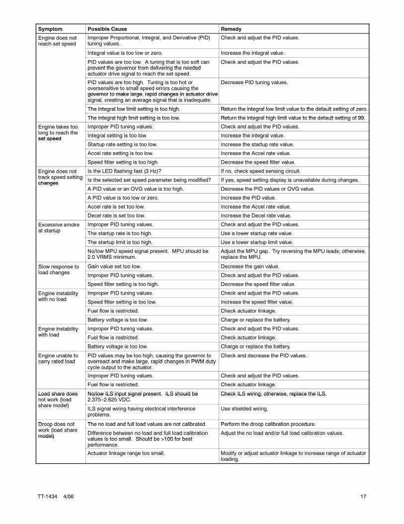
Symptom RemedyPossible Cause
Engine does notreach set speed
Improper Proportional, Integral, and Derivative (PID)tuning values.
Check and adjust the PID values.p
Integral value is too low or zero. Increase the integral value.
PID values are too low. A tuning that is too soft canprevent the governor from delivering the needed
Check and adjust the PID values.prevent the governor from delivering the neededactuator drive signal to reach the set speed.
PID values are too high. Tuning is too hot ori i ll d i h
Decrease PID tuning values.g goversensitive to small speed errors causing thegovernor to make large, rapid changes in actuator drive
g
governor to make large, rapid changes in actuator drivesignal, creating an average signal that is inadequate.
The integral low limit setting is too high Return the integral low limit value to the default setting of zeroThe integral low limit setting is too high. Return the integral low limit value to the default setting of zero.
The integral high limit setting is too low Return the integral high limit value to the default setting of 99The integral high limit setting is too low. Return the integral high limit value to the default setting of 99.
Engine takes tool h h
Improper PID tuning values. Check and adjust the PID values.glong to reach theset speed
Integral setting is too low. Increase the integral value.set speed
Startup rate setting is too low. Increase the startup rate value.
Accel rate setting is too low. Increase the Accel rate value.
Speed filter setting is too high. Decrease the speed filter value.
Engine does notk d i
Is the LED flashing fast (3 Hz)? If no, check speed sensing circuit.gtrack speed settingchanges
Is the selected set speed parameter being modified? If yes, speed setting display is unavailable during changes.changes
A PID value or an OVG value is too high. Decrease the PID values or OVG value.
A PID value is too low or zero. Increase the PID value.
Accel rate is set too low. Increase the Accel rate value.
Decel rate is set too low. Increase the Decel rate value.
Excessive smoke Improper PID tuning values. Check and adjust the PID values.at startup
The startup rate is too high. Use a lower startup rate value.
The startup limit is too high. Use a lower startup limit value.
No/low MPU speed signal present. MPU should be2.0 VRMS minimum.
Adjust the MPU gap. Try reversing the MPU leads; otherwise,replace the MPU.
Slow response tol d h
Gain value set too low. Decrease the gain value.pload changes
Improper PID tuning values. Check and adjust the PID values.
Speed filter setting is too high. Decrease the speed filter value.
Engine instabilityi h l d
Improper PID tuning values. Check and adjust the PID values.g ywith no load
Speed filter setting is too low. Increase the speed filter value.
Fuel flow is restricted. Check actuator linkage.
Battery voltage is too low. Charge or replace the battery.
Engine instabilityi h l d
Improper PID tuning values. Check and adjust the PID values.g ywith load
Fuel flow is restricted. Check actuator linkage.
Battery voltage is too low. Charge or replace the battery.
Engine unable tocarry rated load
PID values may be too high, causing the governor tooverreact and make large rapid changes in PWM duty
Check and decrease the PID values.carry rated load overreact and make large, rapid changes in PWM duty
cycle output to the actuator.
Improper PID tuning values. Check and adjust the PID values.
Fuel flow is restricted. Check actuator linkage.
Load share does No/low ILS input signal present. ILS should be Check ILS wiring; otherwise, replace the ILS.Load share doesnot work (loadh d l)
No/low ILS input signal present. ILS should be2.375--2.625 VDC.
Check ILS wiring; otherwise, replace the ILS.(
share model)ILS signal wiring having electrical interferenceproblems.
Use shielded wiring.
Droop does not The no load and full load values are not calibrated Perform the droop calibration procedureDroop does notk (l d h
The no load and full load values are not calibrated. Perform the droop calibration procedure.pwork (load sharemodel)
Difference between no load and full load calibrationvalues is too small Should be >100 for best
Adjust the no load and/or full load calibration values.model)
values is too small. Should be >100 for bestperformance.
Actuator linkage range too small. Modify or adjust actuator linkage to increase range of actuatorloading.
18 TT-1434 4/06
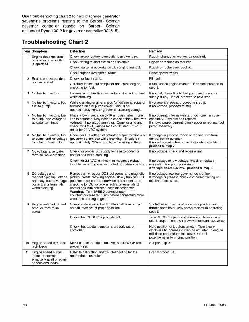
Use troubleshooting chart 2 to help diagnose generator
set/engine problems relating to the Barber- Colman
governor controller (based on Barber- Colman
document Dyna 130-2 for governor controller 324515).
Troubleshooting Chart 2
Item Symptom Detection Remedy
1 Engine does not crankh i h
Check proper battery connections and voltage. Repair, change, or replace as required.gover when start switchis operated
Check wiring to start switch and solenoid. Repair or replace as required.is operated
Check starter in accordance with engine manual. Repair or replace as required.
Check tripped overspeed switch. Reset speed switch.
2 Engine cranks but doesfi
Check for fuel in tank. Fill tank.gnot fire or start
Carefully loosen nut at injector and crank engine,checking for fuel.
If fuel, check engine manual. If no fuel, proceed tostep 3.
3 No fuel to injectors Loosen return fuel line connector and check for fuelwhile cranking.
If no fuel, check line to fuel pump and pressuresupply, if any. If fuel, proceed to next step.
4 No fuel to injectors, butfuel to pump
While cranking engine, check for voltage at actuatorterminals on fuel pump cover. Should beapproximately 75% or greater of cranking voltage.
If voltage is present, proceed to step 5.If no voltage, proceed to step 6.
5 No fuel to injectors, fuelto pump, and voltage toactuator terminals
Place a low impedance 0--10 amp ammeter in oneline to actuator. May need to check polarity first withvoltmeter if polarized ammeter. Crank engine andcheck for 4.3 ±1.5 amps for 12 VDC and 2.5 ±1.3amps for 24 VDC system.
If no current, internal wiring, or coil open in coverassembly. Remove and replace.If shows proper current, check cover or replace fuelpump assembly.
6 No fuel to injectors, fuelto pump, and no voltageto actuator terminals
Check for DC voltage at actuator output terminals ofgovernor control box while cranking. Should beapproximately 75% or greater of cranking voltage.
If voltage is present, repair or replace wire fromcontrol box to actuator.If no voltage at actuator terminals while cranking,proceed to step 7.
7 No voltage at actuatorterminal while cranking
Check for proper DC supply voltage to governorcontrol box while cranking.
If no voltage, check and repair wiring.g
Check for 2.5 VAC minimum at magnetic pickupinput terminal to governor control box while cranking.
If no voltage or low voltage, check or replacemagnetic pickup and/or wiring.If voltage above 2.5 VAC, proceed to step 8.
8 DC voltage andmagnetic pickup voltageare okay, but no voltageout actuator terminalswhen cranking
Remove all wires but DC input power and magneticpickup. While cranking engine, slowly turn SPEEDpotentiometer on box clockwise at least ten turns,checking for DC voltage at actuator terminals ofcontrol box with actuator leads disconnected.Warning: Turn SPEED potentiometercounterclockwise ten turns before connecting otherwires and starting engine.
If no voltage, replace governor control box.If voltage is present, check and correct wiring ofdisconnected wires.
9 Engine runs but will notproduce maximumpower
Check to determine that throttle shaft lever and/orshutoff lever are at proper position.
Shutoff lever must be at maximum position andthrottle shaft lever 12% above maximum operatingspeed.p
Check that DROOP is properly set. Turn DROOP adjustment screw counterclockwiseuntil it stops. Turn the screw two full turns clockwise.
Check that L potentiometer is properly set oncontroller.
Note position of L potentiometer. Turn slowlyclockwise to increase current to actuator. If enginestill does not produce full power, return Lpotentiometer to original position.
10 Engine speed erratic athigh loads
Make certain throttle shaft lever and DROOP areproperly set.
Set per step 9.
11 Engine speed surges,jitters, or operateserratically at all or somespeeds and loads
Refer to calibration and troubleshooting for theappropriate controller.
Follow procedure.
TT-1434 4/06 19
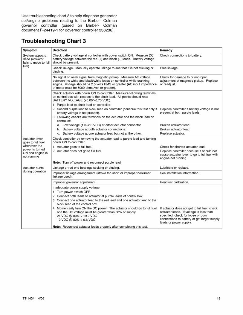
Use troubleshooting chart 3 to help diagnose generator
set/engine problems relating to the Barber- Colman
governor controller (based on Barber- Colman
document F-24419-1 for governor controller 336236).
Troubleshooting Chart 3
Symptom Detection Remedy
System appearsdead (actuatorfails to move to fullf l)
Check battery voltage at controller with power switch ON. Measure DCbattery voltage between the red (+) and black (--) leads. Battery voltageshould be present.
Check connections to battery.
fuel)Check linkage. Manually operate linkage to see that it is not sticking orbinding.
Free linkage.
No signal or weak signal from magnetic pickup. Measure AC voltagebetween the white and black/white leads on controller while crankingengine. Voltage should be 2.5 volts RMS or greater (AC input impedanceof meter must be 5000 ohms/volt or greater).
Check for damage to or improperadjustment of magnetic pickup. Replaceor readjust.
Check actuator with power ON to controller. Measure following terminalson control box with respect to the black lead. All points should readBATTERY VOLTAGE (+0.00/--0.75 VDC).
1. Purple lead to black lead on controller.
2. Second purple lead to black lead on controller (continue this test only if
battery voltage is not present).
Replace controller if battery voltage is notpresent at both purple leads.
3. Following checks are terminals on the actuator and the black lead on
controller:
a. Low voltage (1.0--2.0 VDC) at either actuator connector. Broken actuator lead.
b. Battery voltage at both actuator connections. Broken actuator lead.
c. Battery voltage at one actuator lead but not at the other. Replace actuator.
Actuator levergoes to full fuelh th
Check controller by removing the actuator lead to purple lead and turningpower ON to controller.g
whenever thepower is turned
1. Actuator goes to full fuel. Check for shorted actuator lead.power is turnedON and engine isnot running
2. Actuator does not go to full fuel. Replace controller because it should notcause actuator lever to go to full fuel withengine not running.
Note: Turn off power and reconnect purple lead.
Actuator huntsd i i
Linkage or rod end bearings sticking or binding. Lubricate or replace.during operation
Improper linkage arrangement (stroke too short or improper nonlinearlinkage used).
See installation information.
Improper governor adjustment. Readjust calibration.
Inadequate power supply voltage.
1. Turn power switch OFF.
2. Connect both leads to actuator at purple leads of control box.
3. Connect one actuator lead to the red lead and one actuator lead to the
black lead of the control box.
4. Momentarily turn ON the DC power. The actuator should go to full fuel
and the DC voltage must be greater than 80% of supply.24 VDC @ 80% = 19.2 VDC
12 VDC @ 80% = 9.6 VDC
If actuator does not get to full fuel, checkactuator leads. If voltage is less thanspecified, check for loose or poorconnections to battery or get larger supplyleads or power supply.
Note: Reconnect actuator leads properly after completing this test.