
TSM K DCI Series - Airwell
56
Service Manual K DCI Inverter series REFRIGERANT R410A HEAT PUMP Indoor Units Outdoor Units K 9 DCI INV GC9 DCI INV K 12 DCI INV GC12 DCI INV K 18 DCI INV GC18 DCI INV TM KDCI-A-1-GB DECEMBER 2004
Transcript of TSM K DCI Series - Airwell
Service ManualK DCI Inverter series
REFRIGERANT R410A
HEAT PUMP
Indoor Units Outdoor Units
K 9 DCI INV GC9 DCI INV
K 12 DCI INV GC12 DCI INV
K 18 DCI INV GC18 DCI INV
TM KDCI-A-1-GB DECEMBER 2004

A
LIST OF EFFECTIVE PAGES
Revision Y05-02 Service Manual − K DCI
LIST OF EFFECTIVE PAGES
Note: Changes in the pages are indicated by a “Revision#” in the footer of each effected page (when none indicates no changes in the relevant page). All pages in the following list represent effected/ non effected pages divided by chapters.
Dates of issue for original and changed pages are:
Original ....... 0 ........ December 2004
Total number of pages in this publication is 62 consisting of the following:
PageNo.
RevisionNo. #
PageNo.
RevisionNo. #
PageNo.
RevisionNo. #
Title ....................... 0A ........................... 0i ............................. 01-1 - 1-4 ................ 02-1 - 2-4 ................ 03-1 - 3-2 ................ 04-1 - 4-2 ................ 05-1 - 5-12 .............. 06-1 - 6-8 ................ 07-1 - 7-2 ................ 08-1 - 8-2 ................ 19-1 - 9-2 ................ 010-1-10-2 .............. 011-1-11-16 ............. 212-1-12-8 .............. 013-1-13-10 ............ 0Appendix -A ...........0
• Zero in this column indicates an original page.
*Due to constant improvements please note that the data on this service manual can be modified with out notice.**Photos are not contractual
i
TABLE OF CONTENTS
Service Manual - K DCI
Table of Contents
1. INTRODUCTION ...................................................................................................1-1
2. PRODUCT DATA SHEET ......................................................................................2-1
3. RATING CONDITIONS ..........................................................................................3-1
4. OUTLINE DIMENSIONS .......................................................................................4-1
5. PERFORMANCE DATA .......................................................................................5-1
6. PRESSURE CURVES ...........................................................................................6-1
7. ELECTRICAL DATA ..............................................................................................7-1
8. WIRING DIAGRAMS .............................................................................................8-1
9. REFRIGERATION DIAGRAMS .............................................................................9-1
10. TUBING CONNECTIONS ......................................................................................10-1
11. CONTROL SYSTEM .............................................................................................11-1
12. TROUBLESHOOTING ..........................................................................................12-1
1-1
INTRODUCTION
Service Manual - K DCI
1. INTRODUCTION1.1 General
The new K DCI INVERTERS split Cassette range comprise the following RC (heat pump) models:
• K 9 DCI INV• K 12 DCI INV
• K 18 DCI INV
The New DCI K units can be easily fitted to residential and commercial applications featuring esthetic design, compact dimensions, and low noise operation.
1.2 Main FeaturesThe K DCI INV series benefits from the most advanced innovations, namely:
• DC Inverter technology • R410A • High COP (level A)• Lego Concept• Pre-Charged units up to the max’ allowing tubing distance • Networking system connectivity • Base heater connection• Cooling operation at outdoor temperature down to -10ºC• Heating operation at outdoor temperature down to -15ºC• Bended indoor coil with treated aluminum fins and coating for improved
efficiency.• Easy access to the interconnecting tubing and wiring connections. • Automatic treated air sweep. • Low indoor and outdoor noise levels. • Easy installation and service.
1-2
INTRODUCTION
Service Manual - K DCI
1.3 Filtration The K DCI INV series presents several types of air filters:
• Easily accessible, and re-usable pre-filters (mesh)• Pre-charged electrostatic filter (disposable) • Active carbon filter (disposable)
1.4 Control The microprocessor indoor and outdoor controllers, and an infrared remote control, supplied as standard, provide complete operating function and programming.
Remote controllers: RC-2/3/4/5/7, RCW, µBMSNetworking system AircoNet version 4.2 and up, MIU SW version H8 and upFor further details please refer to the Operation Manual.
1.5 Outdoor Unit
The K DCI INV outdoor units can be installed as floor or wall mounted units by using a wall supporting bracket. The metal sheets are protected by anti- corrosion paint work allowing long life resistance. All outdoor units are pre-charged. For further information please refer to the Product Data Sheet, Chapter 2.
• GC 9 DCI• GC 12 DCI• GC 18
Outdoor Unit Features:
Features GC 9,12, 18, DCIDisplay 3 LED’s
Base Heater OptionalOutdoor Fan Variable Speed DC Inverter
M2L cable Port No
1.6 Tubing ConnectionsFlare type interconnecting tubing to be produced on site.For further details please refer to the Installation Manual.
1.7 Accessories• MIU (K) MODBUS Interface Unit• Base heater• M2L cable
1.8 Inbox DocumentationEach unit is supplied with its own installation and operation manuals.
1-3
INTRODUCTION
Service Manual - K DCI
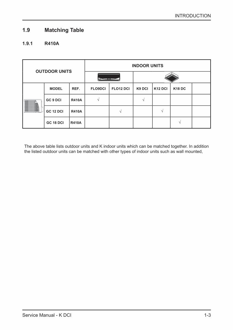
1.9 Matching Table
1.9.1 R410A
OUTDOOR UNITSINDOOR UNITS
MODEL REF. FLO9DCI FLO12 DCI K9 DCI K12 DCI K18 DC
GC 9 DCI R410A
GC 12 DCI R410A
GC 18 DCI R410A
The above table lists outdoor units and K indoor units which can be matched together. In addition the listed outdoor units can be matched with other types of indoor units such as wall mounted, .
√
√√
√√

2-1
PRODUCT DATA SHEET
Service Manual - K DCI
2. PRODUCT DATA SHEET
2.1 K9 DCI
Model Indoor Unit K9 DCIModel Outdoor Unit ONGC9 DCIInstallation Method FlareCharacteristics Units Cooling Heating
Btu/hr 8530 (5120-12970) 11600 (5120-17060) Capacity(1)
W 2500 (1500 - 3800) 3400 (1500 - 5000) Power Input(1) W 590 (420-1000) 915 (400-1500) COP(1) W/W 4.24 3.72 Energy Efficiency Class A A Power Supply V/Ph/Hz 220-240V / 1Ph / 50Hz Rated Current A 2.7 4.2 Starting Current A 10.50Circuit Breaker Rating A 16
Fan Type & Quantity Centrifugal*1Airflow(2) H/M/L m3/hr 570-500-435 600-530-450 External Static Pressure Min-Max Pa N/ASound Power Level(3) H/L dB (A) 42-48 42-47 Sound Pressure Level (4) H/L dB (A) 32-38 32-37 Moisture Removal L/hr 1.0Condensate Drain Tube I.D. mm 16Dimensions W/H/D mm 571 287 571 Weight kg 22.7Package Dimensions W/H/D mm 685 415 685 Units per Pallet Units 10
IND
OO
R
Stacking Height Units 5Refrigerant Control Electronic Expansion Valve Compressor Type, Model Single Rotary DC Inverter Panasonic 5RS102XAB Fan Type & Quantity Axial *1 Airflow H m3/hr 1780Sound Power Level H dB (A) 60 61 Sound Pressure Level (4) H dB (A) 50 51 Dimensions W/H/D mm 795 610 290 Weight kg 40Package Dimensions W/H/D mm 945 655 393 Units per Pallet Units 9Stacking Height Units 3Refrigerant Type R410ARefrigerant Chargeless Distance g 1100Additional Charge Per 1 Meter g/m No Need
Liquid Line (mm)In (6.35) ¼”Suction Line (mm)In (9.53) �”Max. Tubing Length m 20
OU
TDO
OR
ConnectionsBetween Units
Max. Height Difference m 10Operation Control Type IR Remote Control
(1) Rating conditions in accordance with ISO 5151 and ISO 13253 (for ducted units) and EN14511. (2) Airflow in ducted units; at nominal external static pressure. (3) Sound power in ducted units is measured at air discharge. (4) Sound pressure level measured at 1 meter distance from unit.
38395

2-2
PRODUCT DATA SHEET
Service Manual - K DCI
2.2 K12 DCI
Model Indoor Unit K12 DCIModel Outdoor Unit OGC12 DCIInstallation Method FlareCharacteristics Units Cooling Heating
Btu/hr 11940 (5100 - 14960) 14620 (5100 - 18700) Capacity(1)
W 3500 (1500 - 4400) 4300 (1500 - 5500) Power Input(1) W 950 (420-1250) 1330 (400-1850) COP(1) W/W 3.68 3.23 Energy Efficiency Class A A Power Supply V/Ph/Hz 220-240V / 1Ph / 50Hz Rated Current A 4.1 5.6 Starting Current A 10.50Circuit Breaker Rating A 16
Fan Type & Quantity Centrifugal*1Airflow(2) H/M/L m3/hr 580-510-435 620-560-450 External Static Pressure Min-Max Pa N/ASound Power Level(3) H/L dB (A) 42-48 42-47 Sound Pressure Level (4) H/L dB (A) 32-38 32-37 Moisture Removal L/hr 1.5Condensate Drain Tube I.D. mm 16Dimensions W/H/D mm 571 287 571 Weight kg 24.4Package Dimensions W/H/D mm 685 415 685 Units per Pallet Units 10
IND
OO
R
Stacking Height Units 5Refrigerant Control Electronic Expansion Valve Compressor Type, Model Single Rotary DC Inverter Panasonic 5RS102XAB Fan Type & Quantity Axial *1 Airflow H m3/hr 1780Sound Power Level H dB (A) 62 62 Sound Pressure Level (4) H dB (A) 52 52 Dimensions W/H/D mm 795 610 290 Weight kg 40Package Dimensions W/H/D mm 945 655 393 Units per Pallet Units 9Stacking Height Units 3Refrigerant Type R410ARefrigerant Chargeless Distance g 1200Additional Charge Per 1 Meter g/m No Need
Liquid Line (mm)In (6.35) ¼”Suction Line (mm)In (9.53) �”Max. Tubing Length m 20
OU
TDO
OR
ConnectionsBetween Units
Max. Height Difference m 10Operation Control Type IR Remote Control
(1) Rating conditions in accordance with ISO 5151 and ISO 13253 (for ducted units) and EN14511. (2) Airflow in ducted units; at nominal external static pressure. (3) Sound power in ducted units is measured at air discharge. (4) Sound pressure level measured at 1 meter distance from unit.
38395
2-4
PRODUCT DATA SHEET
Service Manual - K DCI
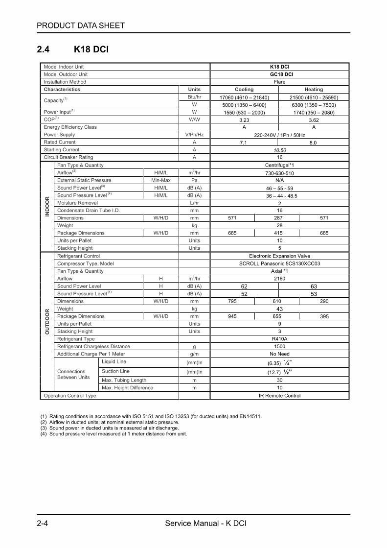
2.4 K18 DCI
Model Indoor Unit K18 DCIModel Outdoor Unit OGC18 DCIInstallation Method FlareCharacteristics Units Cooling Heating
Btu/hr 17060 (4610 – 21840) 21500 (4610 - 25590) Capacity(1)
W 5000 (1350 – 6400) 6300 (1350 – 7500) Power Input(1) W 1550 (530 – 2000) 1740 (350 – 2080) COP(1) W/W 3.23 3.62 Energy Efficiency Class A A Power Supply V/Ph/Hz 220-240V / 1Ph / 50Hz Rated Current A 7.1 8.0 Starting Current A 10.50Circuit Breaker Rating A 16
Fan Type & Quantity Centrifugal*1Airflow(2) H/M/L m3/hr 730-630-510 External Static Pressure Min-Max Pa N/ASound Power Level(3) H/M/L dB (A) 46 – 55 - 59 Sound Pressure Level (4) H/M/L dB (A) 36 – 44 - 48.5 Moisture Removal L/hr 2Condensate Drain Tube I.D. mm 16Dimensions W/H/D mm 571 287 571 Weight kg 28Package Dimensions W/H/D mm 685 415 685 Units per Pallet Units 10
IND
OO
R
Stacking Height Units 5Refrigerant Control Electronic Expansion Valve Compressor Type, Model SCROLL Panasonic 5CS130XCC03 Fan Type & Quantity Axial *1 Airflow H m3/hr 2160Sound Power Level H dB (A) 62 63 Sound Pressure Level (4) H dB (A) 52 53 Dimensions W/H/D mm 795 610 290 Weight kg 43Package Dimensions W/H/D mm 945 655 393 Units per Pallet Units 9Stacking Height Units 3Refrigerant Type R410ARefrigerant Chargeless Distance g 1500Additional Charge Per 1 Meter g/m No Need
Liquid Line (mm)In (6.35) ¼”Suction Line (mm)In (12.7) ½”Max. Tubing Length m 30
OU
TDO
OR
ConnectionsBetween Units
Max. Height Difference m 10Operation Control Type IR Remote Control
(1) Rating conditions in accordance with ISO 5151 and ISO 13253 (for ducted units) and EN14511. (2) Airflow in ducted units; at nominal external static pressure. (3) Sound power in ducted units is measured at air discharge. (4) Sound pressure level measured at 1 meter distance from unit.
395

3-1
RATING CONDITIONS
Service Manual - K DCI
3. RATING CONDITIONSStandard conditions in accordance with ISO 5151, ISO 13253 (for ducted units) and EN 14511.
Cooling:Indoor: 27oC DB 19oC WBOutdoor: 35 oC DB
Heating:Indoor: 20oC DB Outdoor: 7oC DB 6oC WB
3.1 Operating Limits
Indoor Outdoor
CoolingUpper limit 32oC DB 23oC WB 46oC DBLower limit 21oC DB 15oC WB -10oC DB
HeatingUpper limit 27oC DB 24oC DB 18oC WBLower limit 10oC DB -15oC DB -16oC WB
Voltage1PH 198 – 264 V
3PH N/A
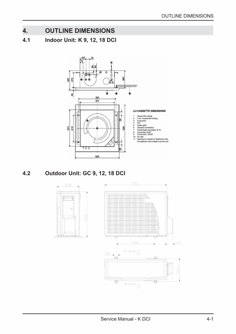
4-1
OUTLINE DIMENSIONS
Service Manual - K DCI
4. OUTLINE DIMENSIONS4.1 Indoor Unit: K 9, 12, 18 DCI
4.2 Outdoor Unit: GC 9, 12, 18 DCI

5-1
PERFORMANCE DATA
Service Manual - K DCI
5. PERFORMANCE DATA5.1 K9 DCI5.1.1 Cooling Capacity (kW) - Run Mode
ID COIL ENTERING AIR DB/WB TEMPERATURE [ºC]
OD COIL ENTERING AIR DB
TEMPERATURE [C0]DATA 22/15 24/17 27/19 29/21 32/23
-10 - 20 (protection range)
TC 80 - 110 % of nominalSC 80 - 105 % of nominalPI 25 - 50 % of nominal
25TC 2.42 2.57 2.73 2.89 3.05SC 2.09 2.13 2.18 2.22 2.26PI 0.46 0.47 0.48 0.49 0.50
30TC 2.30 2.46 2.62 2.77 2.93SC 2.04 2.08 2.12 2.17 2.21PI 0.52 0.53 0.54 0.54 0.55
35TC 2.18 2.34 2.50 2.66 2.82SC 1.98 2.03 2.07 2.11 2.16PI 0.57 0.58 0.59 0.60 0.61
40TC 2.07 2.23 2.38 2.54 2.70SC 1.93 1.97 2.02 2.06 2.10PI 0.63 0.64 0.64 0.65 0.66
46TC 1.93 2.09 2.24 2.40 2.56SC 1.87 1.91 1.95 2.00 2.04PI 0.69 0.70 0.71 0.72 0.73
LEGEND
TC – Total Cooling Capacity, kWSC – Sensible Capacity, kWPI – Power Input, kWWB – Wet Bulb Temp., (oC)DB – Dry Bulb Temp., (oC)ID – IndoorOD – Outdoor
5.1.2 Capacity Correction Factors
Cooling Capacity Ratio Vs. Outdoor Temperature
0.5
0.60.7
0.80.9
1
1.1
1.2
20 25 30 35 40 45
Outdoor Temperature [deg C]
Cap
acity
Rat
ion
5-2
PERFORMANCE DATA
Service Manual - K DCI
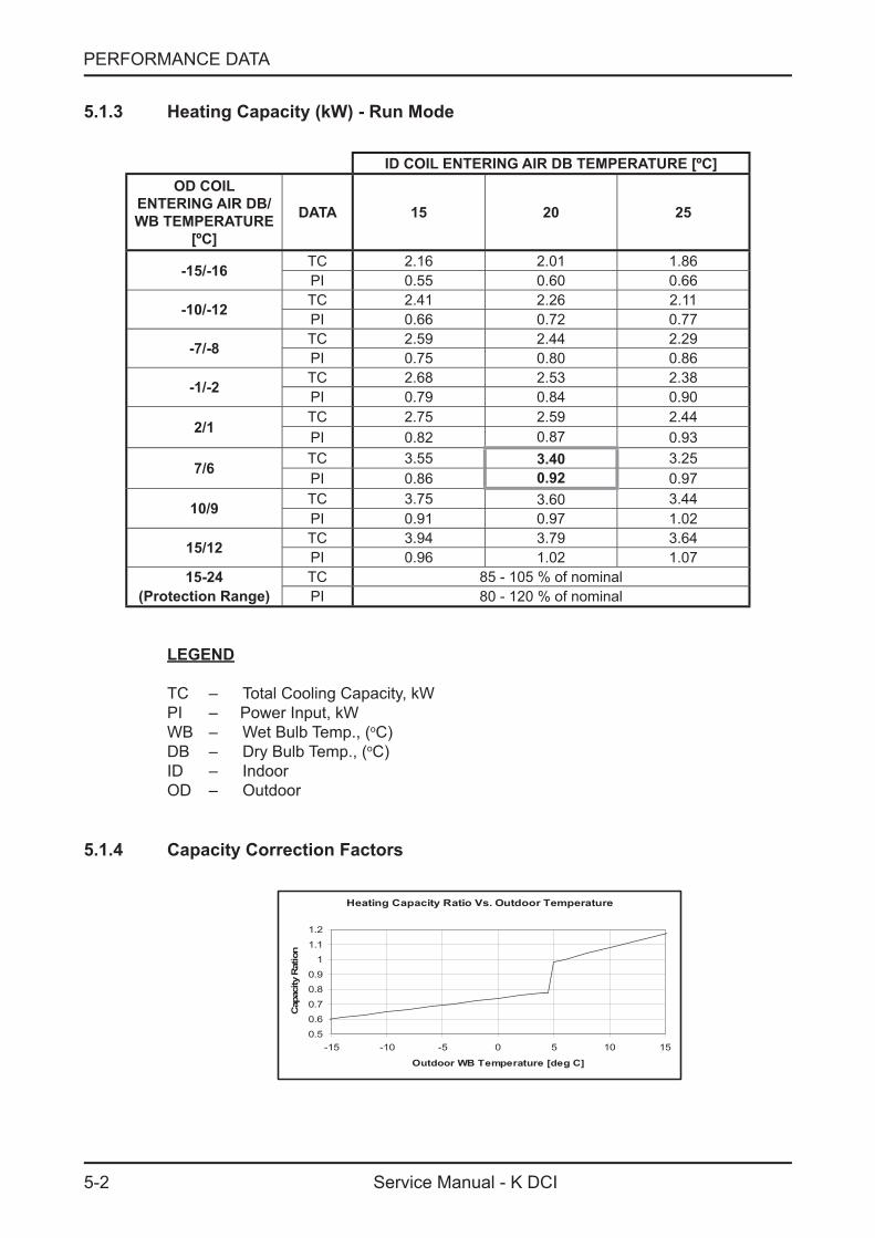
5.1.3 Heating Capacity (kW) - Run Mode
ID COIL ENTERING AIR DB TEMPERATURE [ºC]OD COIL
ENTERING AIR DB/WB TEMPERATURE
[ºC]
DATA 15 20 25
-15/-16 TC 2.16 2.01 1.86PI 0.55 0.60 0.66
-10/-12 TC 2.41 2.26 2.11PI 0.66 0.72 0.77
-7/-8 TC 2.59 2.44 2.29PI 0.75 0.80 0.86
-1/-2 TC 2.68 2.53 2.38PI 0.79 0.84 0.90
2/1TC 2.75 2.59 2.44PI 0.82 0.87 0.93
7/6 TC 3.55 3.40 3.25PI 0.86 0.92 0.97
10/9 TC 3.75 3.60 3.44PI 0.91 0.97 1.02
15/12 TC 3.94 3.79 3.64PI 0.96 1.02 1.07
15-24 TC 85 - 105 % of nominal(Protection Range) PI 80 - 120 % of nominal
LEGEND
TC – Total Cooling Capacity, kWPI – Power Input, kWWB – Wet Bulb Temp., (oC)DB – Dry Bulb Temp., (oC)ID – IndoorOD – Outdoor
5.1.4 Capacity Correction Factors
Heating Capacity Ratio Vs. Outdoor Temperature
0.50.6
0.7
0.80.9
11.1
1.2
-15 -10 -5 0 5 10 15
Outdoor WB Temperature [deg C]
Cap
acity
Rat
ion
5-3
PERFORMANCE DATA
Service Manual - K DCI
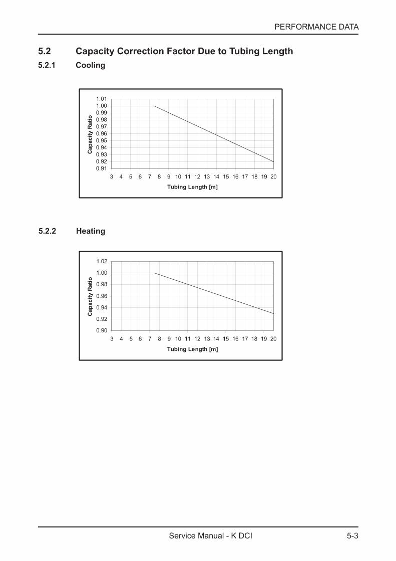
5.2 Capacity Correction Factor Due to Tubing Length5.2.1 Cooling
0.910.920.930.940.950.960.970.980.991.001.01
3 4 5 6 7 8 9 10 11 12 13 14 15 16 17 18 19 20
Tubing Length [m]
Capa
city
Rat
io
5.2.2 Heating
0.90
0.92
0.94
0.96
0.98
1.00
1.02
3 4 5 6 7 8 9 10 11 12 13 14 15 16 17 18 19 20
Tubing Length [m]
Cap
acity
Rat
io
5-4
PERFORMANCE DATA
Service Manual - K DCI
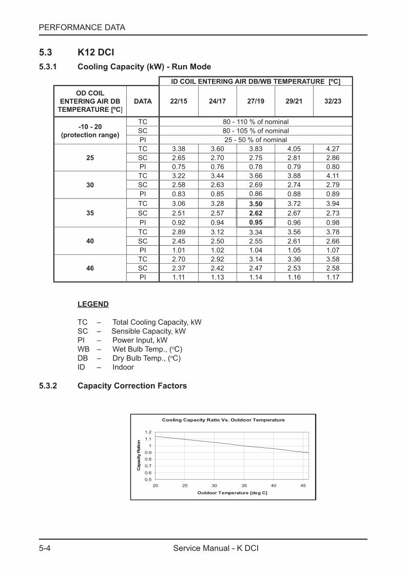
5.3 K12 DCI5.3.1 Cooling Capacity (kW) - Run Mode
ID COIL ENTERING AIR DB/WB TEMPERATURE [ºC]OD COIL
ENTERING AIR DB TEMPERATURE [ºC]
DATA 22/15 24/17 27/19 29/21 32/23
-10 - 20 (protection range)
TC 80 - 110 % of nominalSC 80 - 105 % of nominalPI 25 - 50 % of nominal
25TC 3.38 3.60 3.83 4.05 4.27SC 2.65 2.70 2.75 2.81 2.86PI 0.75 0.76 0.78 0.79 0.80
30TC 3.22 3.44 3.66 3.88 4.11SC 2.58 2.63 2.69 2.74 2.79PI 0.83 0.85 0.86 0.88 0.89
35TC 3.06 3.28 3.50 3.72 3.94SC 2.51 2.57 2.62 2.67 2.73PI 0.92 0.94 0.95 0.96 0.98
40TC 2.89 3.12 3.34 3.56 3.78SC 2.45 2.50 2.55 2.61 2.66PI 1.01 1.02 1.04 1.05 1.07
46TC 2.70 2.92 3.14 3.36 3.58SC 2.37 2.42 2.47 2.53 2.58PI 1.11 1.13 1.14 1.16 1.17
LEGEND
TC – Total Cooling Capacity, kWSC – Sensible Capacity, kWPI – Power Input, kWWB – Wet Bulb Temp., (oC)DB – Dry Bulb Temp., (oC)ID – Indoor
5.3.2 Capacity Correction Factors
Cooling Capacity Ratio Vs. Outdoor Temperature
0.50.6
0.7
0.80.9
1
1.1
1.2
20 25 30 35 40 45
Outdoor Temperature [deg C]
Cap
acity
Rat
ion
5-5
PERFORMANCE DATA
Service Manual - K DCI
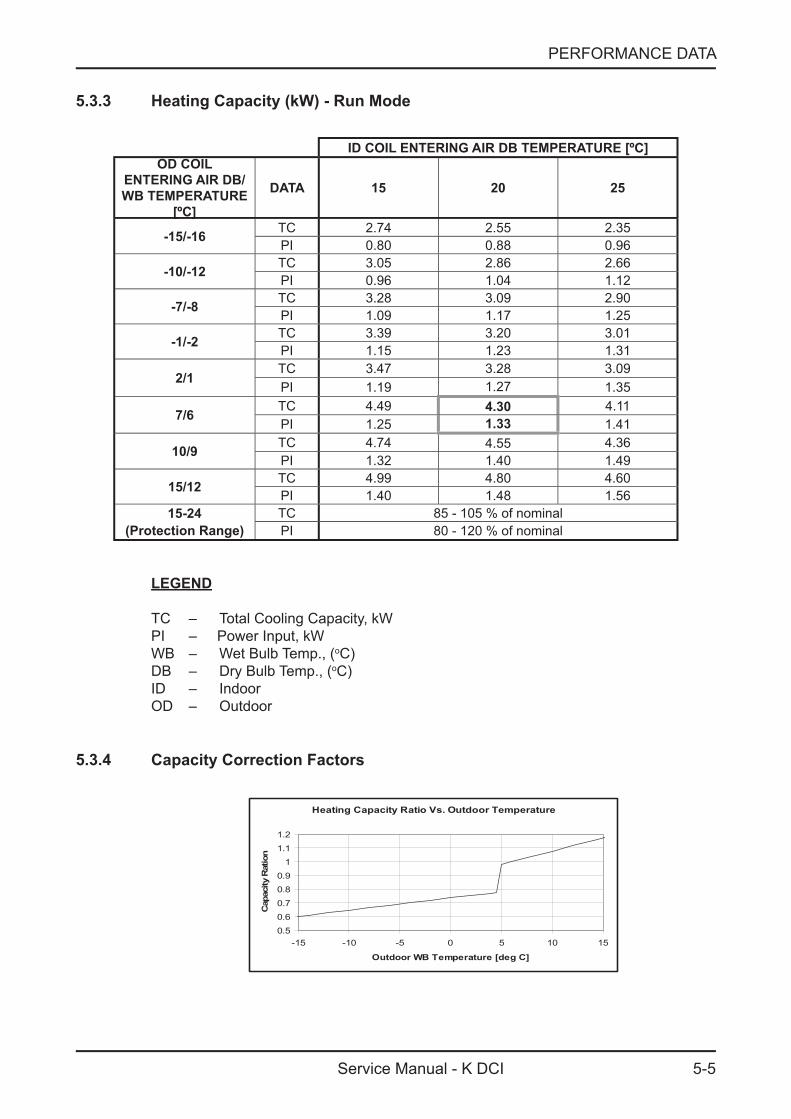
5.3.3 Heating Capacity (kW) - Run Mode
ID COIL ENTERING AIR DB TEMPERATURE [ºC]OD COIL
ENTERING AIR DB/WB TEMPERATURE
[ºC]
DATA 15 20 25
-15/-16 TC 2.74 2.55 2.35PI 0.80 0.88 0.96
-10/-12 TC 3.05 2.86 2.66PI 0.96 1.04 1.12
-7/-8 TC 3.28 3.09 2.90PI 1.09 1.17 1.25
-1/-2 TC 3.39 3.20 3.01PI 1.15 1.23 1.31
2/1TC 3.47 3.28 3.09PI 1.19 1.27 1.35
7/6 TC 4.49 4.30 4.11PI 1.25 1.33 1.41
10/9 TC 4.74 4.55 4.36PI 1.32 1.40 1.49
15/12 TC 4.99 4.80 4.60PI 1.40 1.48 1.56
15-24 TC 85 - 105 % of nominal(Protection Range) PI 80 - 120 % of nominal
LEGEND
TC – Total Cooling Capacity, kWPI – Power Input, kWWB – Wet Bulb Temp., (oC)DB – Dry Bulb Temp., (oC)ID – IndoorOD – Outdoor
5.3.4 Capacity Correction Factors
Heating Capacity Ratio Vs. Outdoor Temperature
0.5
0.6
0.7
0.8
0.9
1
1.1
1.2
-15 -10 -5 0 5 10 15
Outdoor WB Temperature [deg C]
Cap
acity
Rat
ion

5-6
PERFORMANCE DATA
Service Manual - K DCI
5.4 Capacity Correction Factor Due to Tubing Length5.4.1 Cooling
0.910.920.930.940.950.960.970.980.991.001.01
3 4 5 6 7 8 9 10 11 12 13 14 15 16 17 18 19 20
Tubing Length [m]
Cap
acity
Rat
io
5.4.2 Heating
0.90
0.92
0.94
0.96
0.98
1.00
1.02
3 4 5 6 7 8 9 10 11 12 13 14 15 16 17 18 19 20
Tubing Length [m]
Capa
city
Rat
io
5-10
PERFORMANCE DATA
Service Manual - K DCI
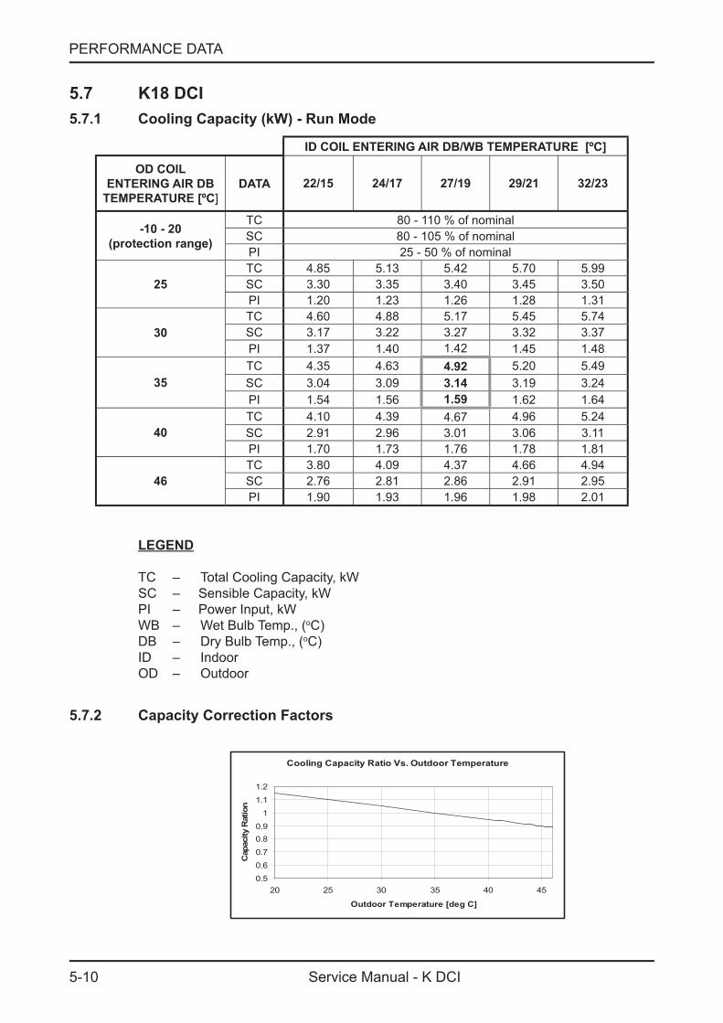
5.7 K18 DCI5.7.1 Cooling Capacity (kW) - Run Mode
ID COIL ENTERING AIR DB/WB TEMPERATURE [ºC]
OD COIL ENTERING AIR DB
TEMPERATURE [ºC]DATA 22/15 24/17 27/19 29/21 32/23
-10 - 20 (protection range)
TC 80 - 110 % of nominalSC 80 - 105 % of nominalPI 25 - 50 % of nominal
25TC 4.85 5.13 5.42 5.70 5.99SC 3.30 3.35 3.40 3.45 3.50PI 1.20 1.23 1.26 1.28 1.31
30TC 4.60 4.88 5.17 5.45 5.74SC 3.17 3.22 3.27 3.32 3.37PI 1.37 1.40 1.42 1.45 1.48
35TC 4.35 4.63 4.92 5.20 5.49SC 3.04 3.09 3.14 3.19 3.24PI 1.54 1.56 1.59 1.62 1.64
40TC 4.10 4.39 4.67 4.96 5.24SC 2.91 2.96 3.01 3.06 3.11PI 1.70 1.73 1.76 1.78 1.81
46TC 3.80 4.09 4.37 4.66 4.94SC 2.76 2.81 2.86 2.91 2.95PI 1.90 1.93 1.96 1.98 2.01
LEGEND
TC – Total Cooling Capacity, kWSC – Sensible Capacity, kWPI – Power Input, kWWB – Wet Bulb Temp., (oC)DB – Dry Bulb Temp., (oC)ID – IndoorOD – Outdoor
5.7.2 Capacity Correction Factors
Cooling Capacity Ratio Vs. Outdoor Temperature
0.5
0.60.7
0.80.9
1
1.1
1.2
20 25 30 35 40 45
Outdoor Temperature [deg C]
Cap
acity
Rat
ion
5-11
PERFORMANCE DATA
Service Manual - K DCI
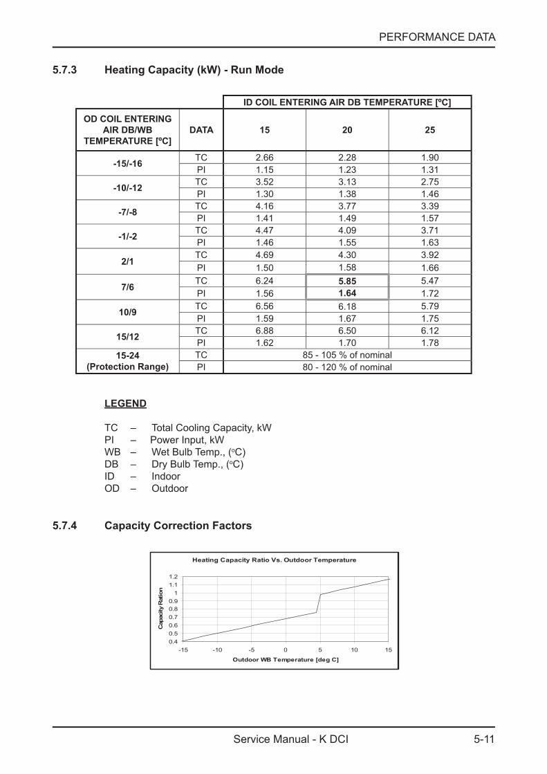
5.7.3 Heating Capacity (kW) - Run Mode
ID COIL ENTERING AIR DB TEMPERATURE [ºC]
OD COIL ENTERING AIR DB/WB
TEMPERATURE [ºC] DATA 15 20 25
-15/-16 TC 2.66 2.28 1.90PI 1.15 1.23 1.31
-10/-12 TC 3.52 3.13 2.75PI 1.30 1.38 1.46
-7/-8 TC 4.16 3.77 3.39PI 1.41 1.49 1.57
-1/-2 TC 4.47 4.09 3.71PI 1.46 1.55 1.63
2/1TC 4.69 4.30 3.92PI 1.50 1.58 1.66
7/6 TC 6.24 5.85 5.47PI 1.56 1.64 1.72
10/9 TC 6.56 6.18 5.79PI 1.59 1.67 1.75
15/12 TC 6.88 6.50 6.12PI 1.62 1.70 1.78
15-24(Protection Range)
TC 85 - 105 % of nominalPI 80 - 120 % of nominal
LEGEND
TC – Total Cooling Capacity, kWPI – Power Input, kWWB – Wet Bulb Temp., (oC)DB – Dry Bulb Temp., (oC)ID – IndoorOD – Outdoor
5.7.4 Capacity Correction Factors
Heating Capacity Ratio Vs. Outdoor Temperature
0.40.50.60.70.80.9
11.11.2
-15 -10 -5 0 5 10 15
Outdoor WB Temperature [deg C]
Cap
acity
Rat
ion
5-12
PERFORMANCE DATA
Service Manual - K DCI
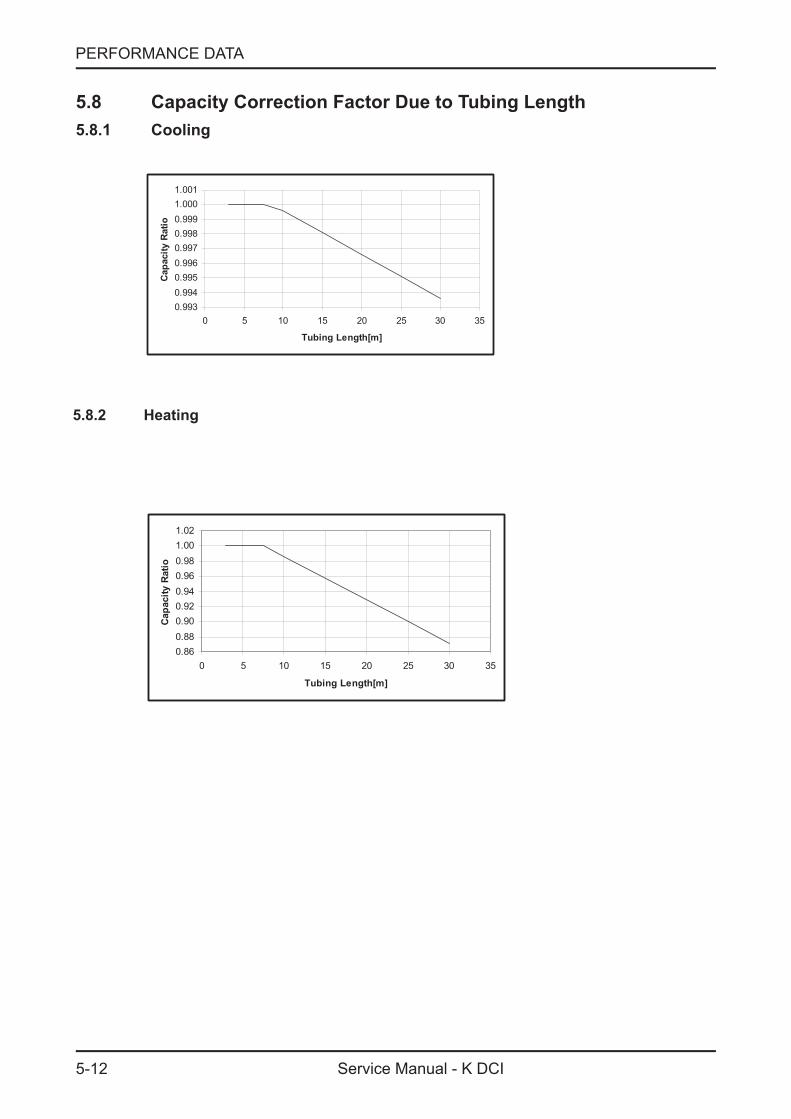
5.8 Capacity Correction Factor Due to Tubing Length5.8.1 Cooling
0.9930.9940.9950.9960.9970.9980.9991.0001.001
0 5 10 15 20 25 30 35
Tubing Length[m]
Capa
city
Rat
io
5.8.2 Heating
0.860.880.900.920.940.960.981.001.02
0 5 10 15 20 25 30 35
Tubing Length[m]
Capa
city
Rat
io
6-1
PRESSURE CURVES
Service Manual - K DCI
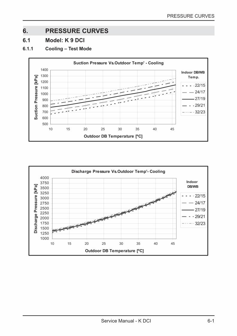
6. PRESSURE CURVES6.1 Model: K 9 DCI6.1.1 Cooling – Test Mode
Suction Pressure Vs.Outdoor Temp' - Cooling
500
600
700
800
900
1000
1100
1200
1300
1400
10 15 20 25 30 35 40 45
Outdoor DB Temperature [ºC]
Suc
tion
Pre
ssur
e [k
Pa]
22/1524/1727/1929/2132/23
Indoor DB/WB Temp.
Discharge Pressure Vs.Outdoor Temp'- Cooling
1000125015001750200022502500275030003250350037504000
10 15 20 25 30 35 40 45
Outdoor DB Temperature [ºC]
Disc
harg
e P
ress
ure
[kP
a]
22/1524/1727/1929/2132/23
Indoor DB/WB
6-2
PRESSURE CURVES
Service Manual - K DCI
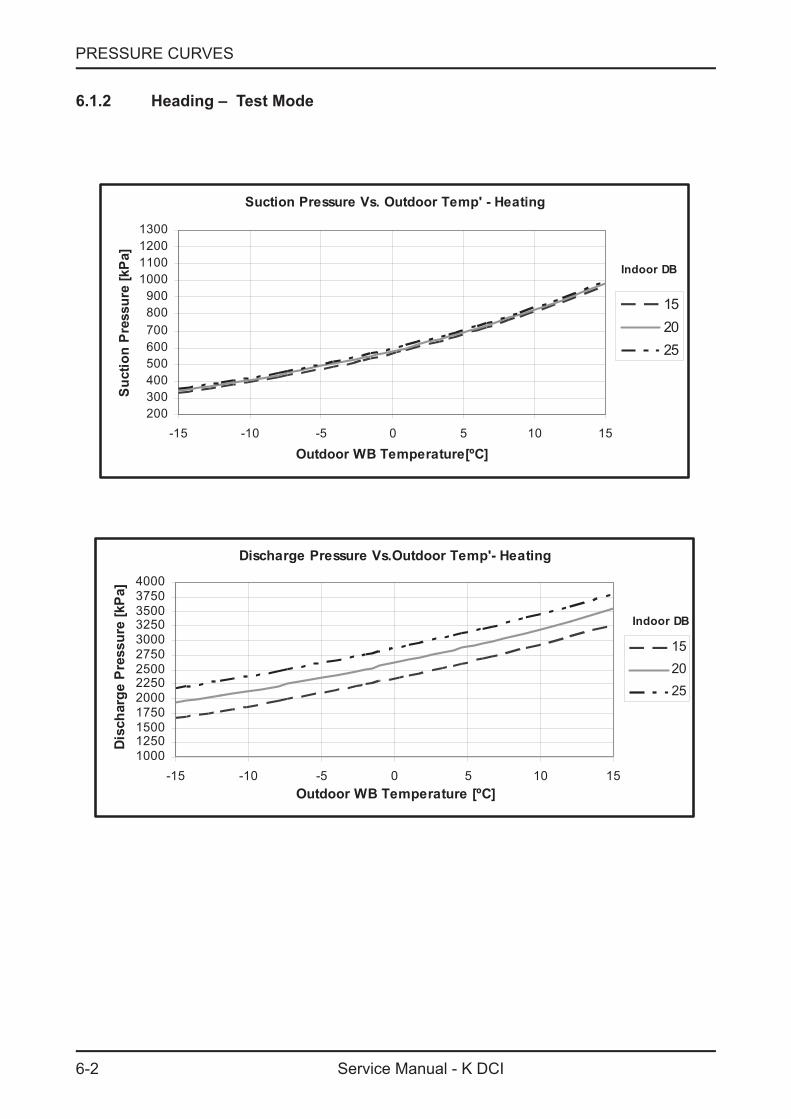
6.1.2 Heading – Test Mode
Suction Pressure Vs. Outdoor Temp' - Heating
200300400500600700800900
1000110012001300
-15 -10 -5 0 5 10 15
Outdoor WB Temperature[ºC]
Suct
ion
Pres
sure
[kPa
]
152025
Indoor DB
Discharge Pressure Vs.Outdoor Temp'- Heating
1000125015001750200022502500275030003250350037504000
-15 -10 -5 0 5 10 15Outdoor WB Temperature [ºC]
Dis
char
ge P
ress
ure
[kPa
]
152025
Indoor DB

6-3
PRESSURE CURVES
Service Manual - K DCI
6.2 Model: K 12 DCI6.2.1 Cooling – Test Mode
Suction Pressure Vs.Outdoor Temp' - Cooling
500600700800900
10001100120013001400
10 15 20 25 30 35 40 45
Outdoor DB Temperature [ºC]
Suct
ion
Pres
sure
[kP
a]
22/1524/1727/1929/2132/23
Indoor DB/WB
Discharge Pressure Vs.Outdoor Temp'- Cooling
1000125015001750200022502500275030003250350037504000
10 15 20 25 30 35 40 45
Outdoor DB Temperature [ºC]
Disc
harg
e P
ress
ure
[kP
a]
22/1524/1727/1929/2132/23
Indoor DB/WB
6-4
PRESSURE CURVES
Service Manual - K DCI
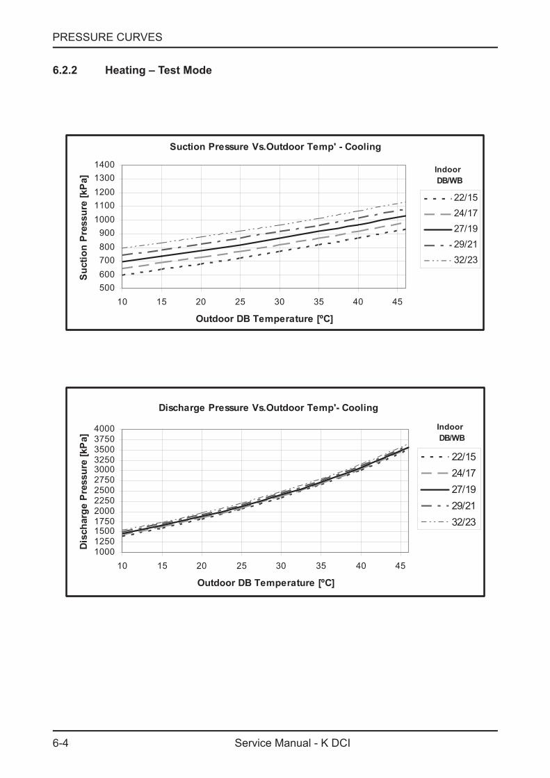
6.2.2 Heating – Test Mode
Suction Pressure Vs.Outdoor Temp' - Cooling
500600700800900
10001100120013001400
10 15 20 25 30 35 40 45
Outdoor DB Temperature [ºC]
Suct
ion
Pres
sure
[kP
a]
22/1524/1727/1929/2132/23
Indoor DB/WB
Discharge Pressure Vs.Outdoor Temp'- Cooling
1000125015001750200022502500275030003250350037504000
10 15 20 25 30 35 40 45
Outdoor DB Temperature [ºC]
Disc
harg
e P
ress
ure
[kP
a]
22/1524/1727/1929/2132/23
Indoor DB/WB

6-7
PRESSURE CURVES
Service Manual - K DCI
6.4 Model: K 18 DCI6.4.1 Cooling – Test Mode
Suction Pressure Vs.Outdoor Temp' - Cooling
500600700800900
10001100120013001400
10 15 20 25 30 35 40 45
Outdoor DB Temperature[ºC]
Suc
tion
Pre
ssur
e [k
Pa]
22/1524/1727/1929/2132/23
Indoor DB/WB
Discharge Pressure Vs.Outdoor Temp' - Cooling
10001250150017502000225025002750300032503500375040004250
10 15 20 25 30 35 40 45
Outdoor DB Temperature[ºC]
Dis
char
ge P
ress
ure
[kPa
]
22/1524/1727/1929/2132/23
Indoor DB/WB
6-8
PRESSURE CURVES
Service Manual - K DCI
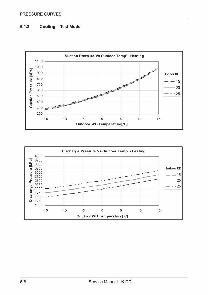
6.4.2 Cooling – Test Mode
Suction Pressure Vs.Outdoor Temp' - Heating
200
300
400
500
600
700
800
900
1000
1100
-15 -10 -5 0 5 10 15Outdoor WB Temperature[ºC]
Suc
tion
Pres
sure
[kPa
]
152025
Discharge Pressure Vs.Outdoor Temp' - Heating
1000125015001750200022502500275030003250350037504000
-15 -10 -5 0 5 10 15
Outdoor WB Temperature[ºC]
Disc
harg
e Pr
essu
re [k
Pa]
152025
Indoor DB
Indoor DB
7-1
ELECTRICAL DATA
Service Manual - K DCI
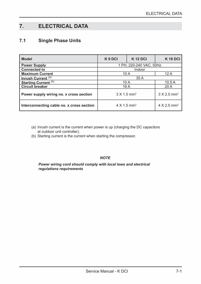
7. ELECTRICAL DATA
7.1 Single Phase Units
Model K 9 DCI K 12 DCI K 18 DCIPower Supply 1 PH, 220-240 VAC, 50HzConnected to IndoorMaximum Current 10 A 12 AInrush Current (a) 35 AStarting Current (b) 10 A 10.5 ACircuit breaker 16 A 20 A
Power supply wiring no. x cross section 3 X 1.5 mm2 3 X 2.5 mm2
Interconnecting cable no. x cross section 4 X 1.5 mm2 4 X 2.5 mm2
(a) Inrush current is the current when power is up (charging the DC capacitors at outdoor unit controller).
(b) Starting current is the current when starting the compressor.
NOTEPower wiring cord should comply with local lows and electrical regulations requirements

8-1
WIRING DIAGRAMS
Service Manual - K DCI
8. WIRING DIAGRAMS
8.1 K9, 12, 18 DCI
esaBretaeh
2
kcalB
eulB
deRMOC
F-L
F-NN
L
MOCNHTRAE
MOC
HTRAE
01P21P
MOCN
LMOC-N
G/Y
G/Y
HTRAE
V 9PU 3P
W31P
11P1
4 P41P
21
1P
lioc ekohC
BrownRed
Black
White
PMOC
Blue
esreveRevlav
YLPPUS REWOP
gnir citengam
nworB
eulB
deRESUF
nworB
deR
G/Y
3/N4/L
5/C
G/Y
8P 3lootagem
7P9PJ
53
12
54
66
EEV3
41
26P
12
71P
Red 61P
Blue
BlackOrangeYellow 12P
22P81P
2 91P12
1 2P
11
2 02P
4TCUS
EARTH 2 1Vdc
4 3 6 5Vsp
Vcc
FG
NAFOTCO
TTCTAO
yalpsiD
2
eulB
G/Y
nworBdeR
Outdo
or Un
it Con
trolle
r PCB
Outdo
or Un
it Circ
uit Di
agram
EM
I filt
er P
CB

9-1
REFRIGERATION DIAGRAMS
Service Manual - K DCI
9. REFRIGERATION DIAGRAMS9.1 K 9, 12,18 DCI
10-1
TUBING CONNECTIONS
Service Manual - K DCI
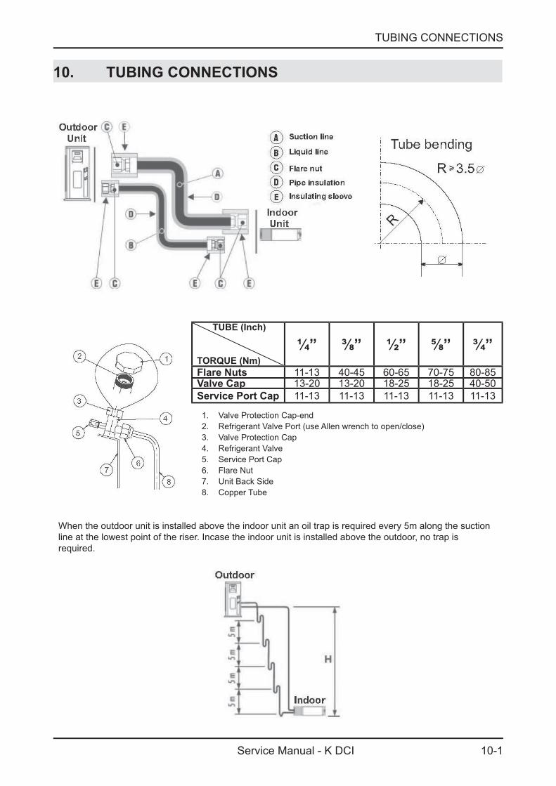
10. TUBING CONNECTIONS
TUBE (Inch)
TORQUE (Nm)¼” ⅜” ½” ⅝” ¾”
Flare Nuts 11-13 40-45 60-65 70-75 80-85Valve Cap 13-20 13-20 18-25 18-25 40-50Service Port Cap 11-13 11-13 11-13 11-13 11-13
1. Valve Protection Cap-end2. Refrigerant Valve Port (use Allen wrench to open/close)3. Valve Protection Cap4. Refrigerant Valve5. Service Port Cap6. Flare Nut7. Unit Back Side8. Copper Tube
When the outdoor unit is installed above the indoor unit an oil trap is required every 5m along the suction line at the lowest point of the riser. Incase the indoor unit is installed above the outdoor, no trap is required.
11-1
CONTROL SYSTEM
Service Manual - K DCI
11. CONTROL SYSTEM
11.1 General Functions and Operating Rules
The DCI software is fully parametric.All the model dependent parameters are shown in Blue color and with Italic style [parameter].The parameters values are given in the last section of this control logic chapter of the servicemanual.
11.1.1 System Operation Concept
The control function is divided between indoor and outdoor unit controllers. Indoor unit is theSystem ‘Master’, requesting the outdoor unit for cooling/heating capacity supply. The outdoor unit isthe system nless it enters into a protection mode'Slave’ and it must supply the required capacityavoiding it from supplying the requested capacity.The capacity request is transferred via indoor to outdoor communication, and is represented by aparameter called ‘NLOAD’. NLOAD is an integer number with values between 0 and 127, and itrepresents the heat or cool load felt by the indoor unit.
11.1.2 Compressor Frequency Control
11.1.2.1 NLOAD setting
The NLOAD setting is done by the indoor unit controller, based on a PI control scheme.The actual NLOAD to be sent to the outdoor unit controller is based on the preliminary LOADcalculation, the indoor fan speed, and the power shedding function.
NLOAD limits as a function of indoor fan speed:
Indoor Fan Speed Maximum NLOAD Cooling Maximum NLOAD Heating
Low Max NLOADIF1C 127
Medium Max NLOADIF2C 127
High Max NLOADIF3C 127
Turbo Max NLOADIF4C 127
Auto Max NLOADIF5C 127
NLOAD limits as a function of power shedding:
Mode Power Shedding OFF Power Shedding ON
Cool No limit Nominal Cooling
Heat No limit Nominal Heating
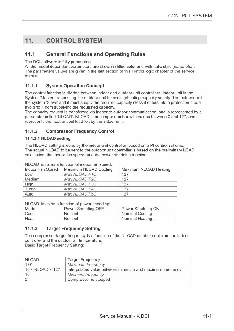
11.1.3 Target Frequency Setting
The compressor target frequency is a function of the NLOAD number sent from the indoorcontroller and the outdoor air temperature.Basic Target Frequency Setting:
NLOAD Target Frequency
127 Maximum frequency
10 < NLOAD < 127 Interpolated value between minimum and maximum frequency
10 Minimum frequency
0 Compressor is stopped
11-2
CONTROL SYSTEM
Service Manual - K DCI
Target frequency limits as a function of outdoor air temperature )OAT(:
OAT Range Cool mode limits Heat mode limits
OAT No limit< 6
6 ≤ OAT < 15 MaxFreqAsOAT1H
15 ≤ OAT < 24
MaxFreqAsOATC
24 ≤ OAT No limitMaxFreqAsOAT2H
11.1.4 Frequency Changes Control
Frequency change rate is 1 Hz/sec.
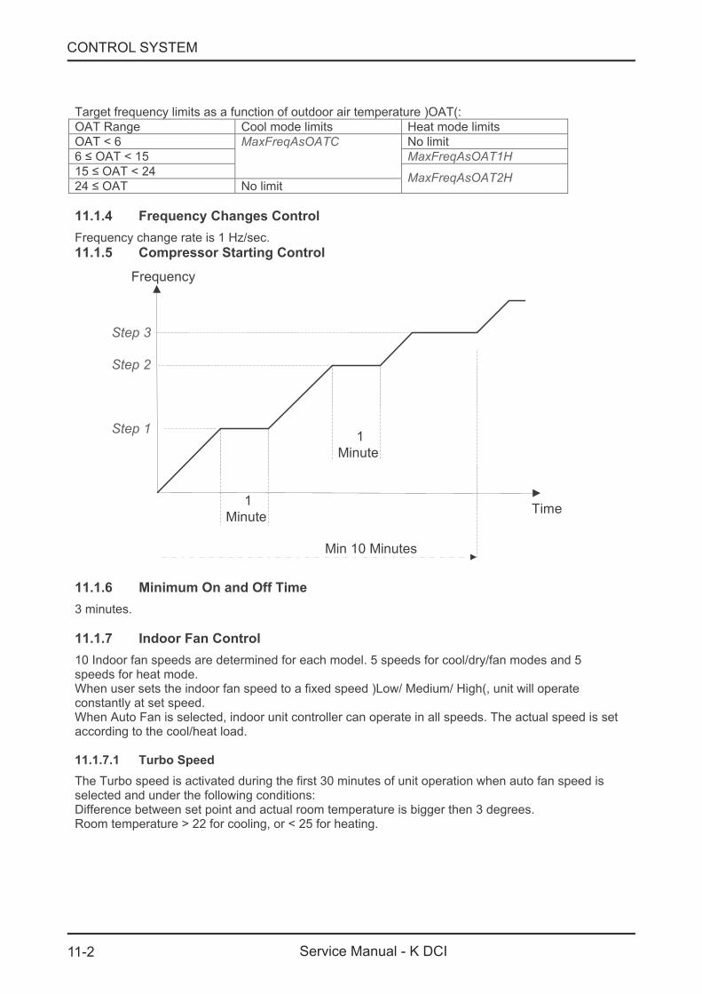
11.1.5 Compressor Starting Control
Frequency
Time
Min 10 Minutes
1
Minute
Step 1
Step 3
1
Minute
Step 2
11.1.6 Minimum On and Off Time
3 minutes.
11.1.7 Indoor Fan Control
10 Indoor fan speeds are determined for each model. 5 speeds for cool/dry/fan modes and 5speeds for heat mode.When user sets the indoor fan speed to a fixed speed )Low/ Medium/ High(, unit will operateconstantly at set speed.When Auto Fan is selected, indoor unit controller can operate in all speeds. The actual speed is setaccording to the cool/heat load.
11.1.7.1 Turbo Speed
The Turbo speed is activated during the first 30 minutes of unit operation when auto fan speed isselected and under the following conditions:Difference between set point and actual room temperature is bigger then 3 degrees.Room temperature 22 for cooling, or 25 for heating.> <
11-3
CONTROL SYSTEM
Service Manual - K DCI
11.1.8 Heating Element Control
Heating element can be started if LOAD 0.8 mumNLOAD AND Indoor Coil temperature> * Maxi<45.The heating element will be stopped when LOAD 0.5 MaximumNLOAD OR if Indoor Coil< *Temperature 50.>
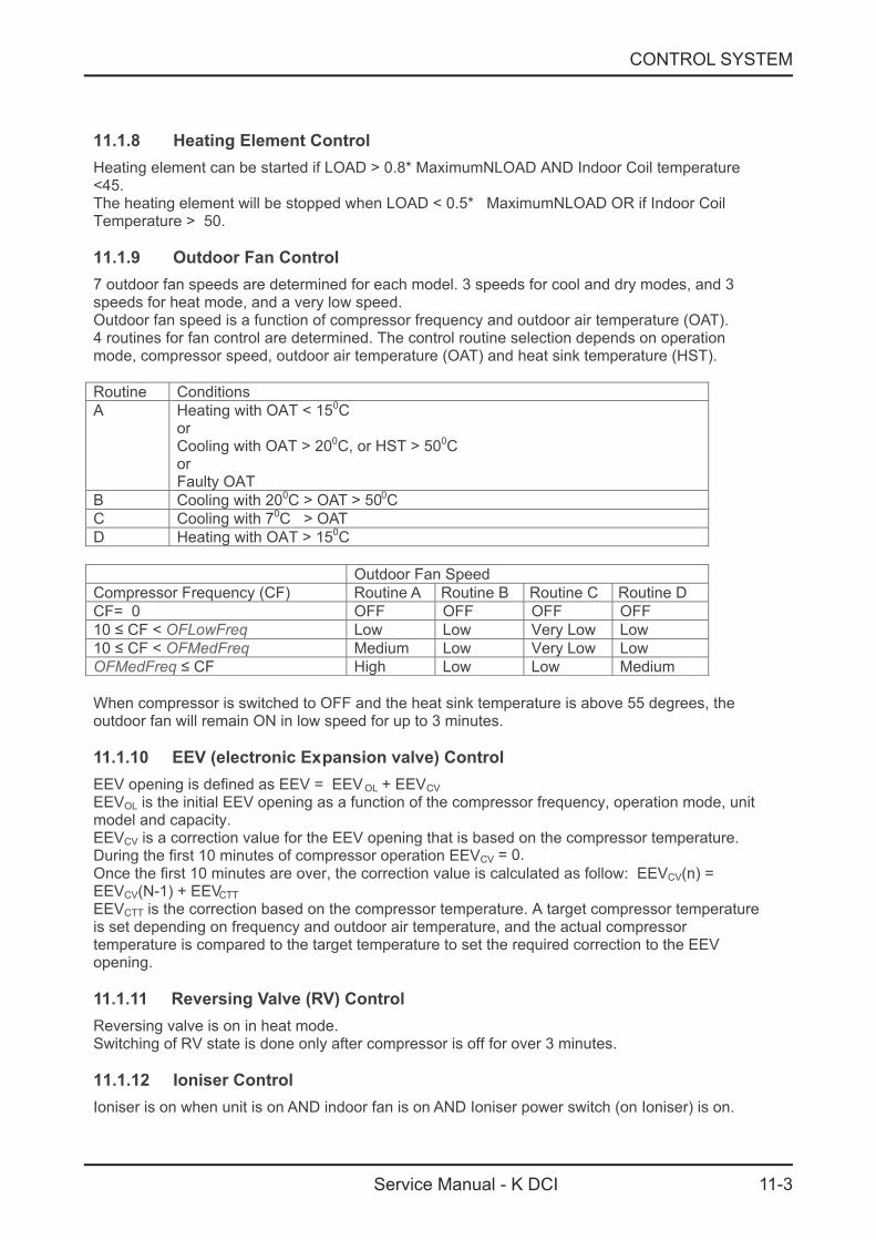
11.1.9 Outdoor Fan Control
7 outdoor fan speeds are determined for each model. 3 speeds for cool and dry modes, and 3speeds for heat mode, and a very low speed.Outdoor fan speed is a function of compressor frequency and outdoor air temperature (OAT).4 routines for fan control are determined. The control routine selection depends on operationmode, compressor speed, outdoor air temperature (OAT) and heat sink temperature (HST).
Routine Conditions
A Heating with OAT 15< 0CorCooling with OAT > 200C, or HST 50> 0CorFaulty OAT
B Cooling with 200C > OAT > 500C
C Cooling with 70C > OAT
D Heating with OAT 15> 0C
Outdoor Fan Speed
Compressor Frequency (CF) Routine A Routine B Routine C Routine D
CF 0 OFF OFF OFF OFF=
10 ≤ CF < OFLowFreq Low Low Very Low Low
10 ≤ CF < OFMedFreq Medium Low Very Low Low
OFMedFreq ≤ CF High Low Low Medium
When compressor is switched to OFF and the heat sink temperature is above 55 degrees, theoutdoor fan will remain ON in low speed for up to 3 minutes.
11.1.10 EEV (electronic Expansion valve) Control
EEV opening is defined as EEV = EEV OL + EEVCV
EEVOL is the initial EEV opening as a function of the compressor frequency, operation mode, unitmodel and capacity.EEVCV is a correction value for the EEV opening that is based on the compressor temperature.During the first 10 minutes of compressor operation EEVCV 0.=
Once the first 10 minutes are over, the correction value is calculated as follow: EEVCV(n) =EEVCV(N-1) + EEVCTT
EEVCTT is the correction based on the compressor temperature. A target compressor temperatureis set depending on frequency and outdoor air temperature, and the actual compressortemperature is compared to the target temperature to set the required correction to the EEVopening.
11.1.11 Reversing Valve (RV) Control
Reversing valve is on in heat mode.Switching of RV state is done only after compressor is off for over 3 minutes.
11.1.12 Ioniser Control
Ioniser is on when unit is on AND indoor fan is on AND Ioniser power switch (on Ioniser) is on.
11-4
CONTROL SYSTEM
Service Manual - K DCI
11.1.13 Electro Static Filter )ESF( Control
ESF is on when ESF switch is on, Safety switch is pressed, unit is on, AND indoor fan is on.
11.1.14 Base Heater Control
When OAT is connected, Base Heater will be on when unit is in heating and OAT<20C.When OAT is disconnected, Base Heater will be on when unit is in heating.
11.2 Fan Mode
In high/ medium/ low indoor fan user setting, unit will operate fan in selected speed.In AutoFan user setting, fan speed will be ad ng to the differencejusti automatically accordingbetween actual room temperature and user set point temperature.
11.3 Cool Mode
NLOAD is calculated according to the difference between actual room temperature and user setpoint temperature by PI control.In high/ medium/ low indoor fan user setting, unit will operate fan in selected speed.In AutoFan user setting, fan speed will be ad8usted automatically according to the calculatedNLOAD.
11.4 Heat Mode
NLOAD is calculated according to the difference between actual room temperature and user setpoint temperature by PI control.In high/ medium/ low indoor fan user setting, unit will operate fan in selected speed.In AutoFan user setting, fan speed will be adng to the calculatedNLOAD.
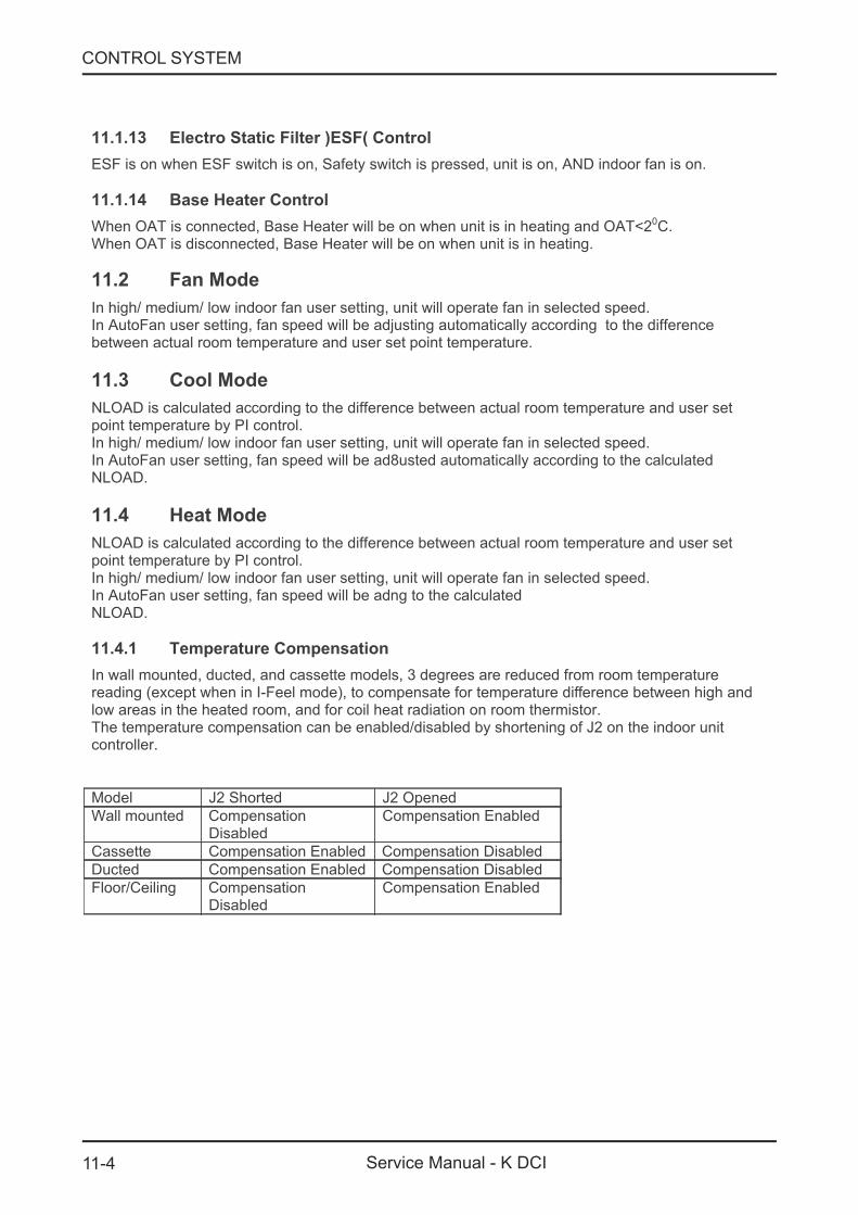
11.4.1 Temperature Compensation
In wall mounted, ducted, and cassette models, 3 degrees are reduced from room temperaturereading (except when in I-Feel mode), to compensate for temperature difference between high andlow areas in the heated room, and for coil heat radiation on room thermistor.The temperature compensation can be enabled/disabled by shortening of J2 on the indoor unitcontroller.
Model J2 Shorted J2 Opened
Wall mounted CompensationDisabled
Compensation Enabled
Cassette Compensation Enabled Compensation Disabled
Ducted Compensation Enabled Compensation Disabled
Floor/Ceiling CompensationDisabled
Compensation Enabled
11-5
CONTROL SYSTEM
Service Manual - K DCI
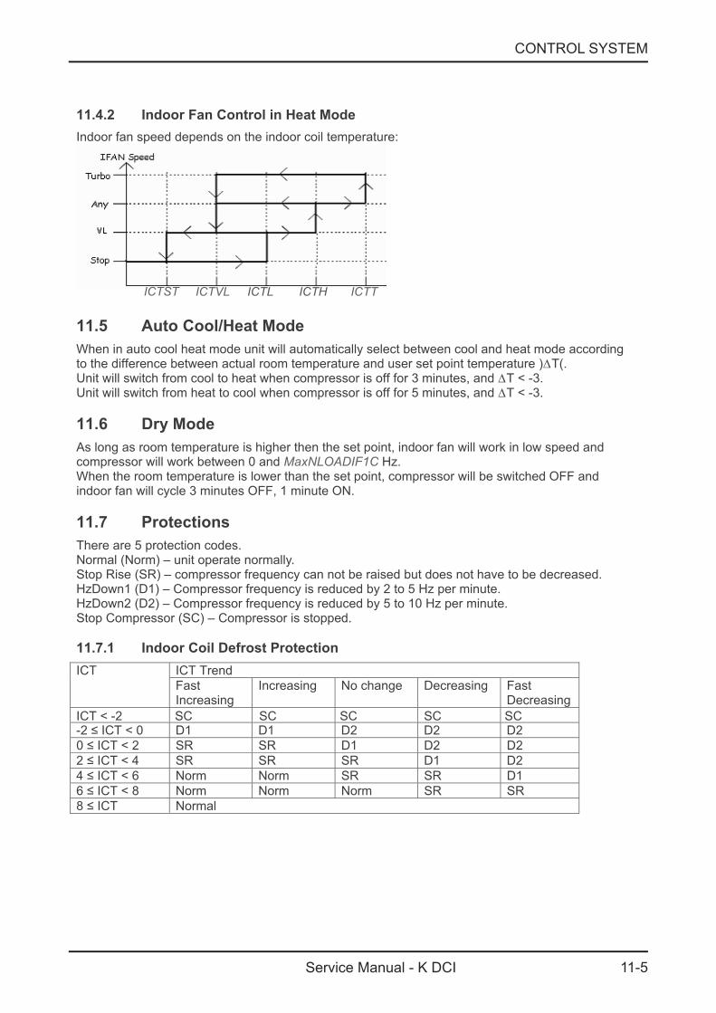
11.4.2 Indoor Fan Control in Heat Mode
Indoor fan speed depends on the indoor coil temperature:
11.5 Auto Cool/Heat Mode
When in auto cool heat mode unit will automatically select between cool and heat mode accordingto the difference between actual room temperature and user set point temperature )∆T(.Unit will switch from cool to heat when compressor is off for 3 minutes, and ∆T < -3.Unit will switch from heat to cool when compressor is off for 5 minutes, and ∆T < -3.
11.6 Dry Mode
As long as room temperature is higher then the set point, indoor fan will work in low speed andcompressor will work between 0 and MaxNLOADIF1C Hz.When the room temperature is lower than the set point, compressor will be switched OFF andindoor fan will cycle 3 minutes OFF, 1 minute ON.
11.7 Protections
There are 5 protection codes.Normal (Norm) – unit operate normally.Stop Rise (SR) – compressor frequency can not be raised but does not have to be decreased.HzDown1 (D1) – Compressor frequency is reduced by 2 to 5 Hz per minute.HzDown2 (D2) – Compressor frequency is reduced by 5 to 10 Hz per minute.Stop Compressor (SC) – Compressor is stopped.
11.7.1 Indoor Coil Defrost Protection
ICT TrendICT
ICT < -2 SC SC SC SC SC
FastIncreasing
Increasing No change Decreasing FastDecreasing
-2 ≤ ICT < 0 D1 D1 D2 D2 D2
0 ≤ ICT < 2 SR SR D1 D2 D2
2 ≤ ICT < 4 SR SR SR D1 D2
4 ≤ ICT < 6 Norm Norm SR SR D1
6 ≤ ICT < 8 Norm Norm Norm SR SR
8 ≤ ICT Normal
ICTST ICTVL ICTTICTHICTL
11-6
CONTROL SYSTEM
Service Manual - K DCI
11.7.2 Indoor Coil over Heating Protection
ICT TrendICT
FastDecreasing
Decreasing No Change Increasing FastIncreasing
ICT 55 SC SC SC SC SC>
53 <ICT ≤ 55 D1 D1 D2 D2 D2
49 < ICT ≤ 53 SR SR D1 D2 D2
47 < ICT ≤ 49 SR SR SR D1 D2
45 < ICT ≤ 47 Norm Norm SR SR D1
43 < ICT ≤ 45 Norm Norm Norm SR SR
ICT ≤ 43 Normal
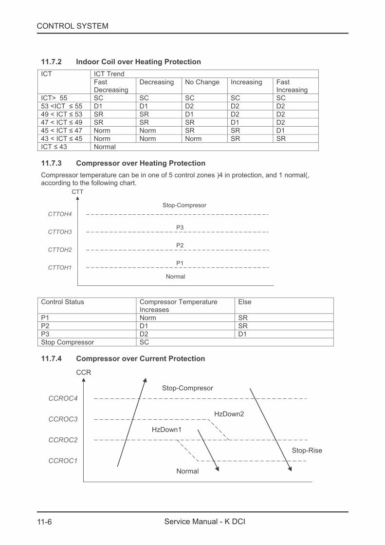
11.7.3 Compressor over Heating Protection
Compressor temperature can be in one of 5 control zones )4 in protection, and 1 normal(,according to the following chart.
Normal
P1
P2
Stop-Compresor
CTTOH1
CTTOH2
CTTOH3
CTTOH4
CTT
P3
Control Status Compressor TemperatureIncreases
Else
P1 Norm SR
P2 D1 SR
P3 D2 D1
Stop Compressor SC
11.7.4 Compressor over Current Protection
Normal
Stop-Rise
HzDown1
HzDown2
Stop-Compresor
CCROC1
CCROC2
CCROC3
CCROC4
CCR

11-7
CONTROL SYSTEM
Service Manual - K DCI
11.7.5 Heat Sink Over Heating Protection (NA for DCI 25 and 35)
HST TrendHST
Decreasing No Change Increasing
HST SC SC SC> 90
85 < HST ≤ 90 D1 D2 D2
82 < HST ≤ 85 SR D1 D2
80 < HST ≤ 82 SR SR D1
78 < HST ≤ 80 Norm Norm SR
HST ≤ 78 Normal
11.7.6 Outdoor Coil Deicing Protection
11.7.6.1 Deicing Starting Conditions
Deicing operation will start when either one of the following conditions exist:Case 1: OCT OAT – 8 AND TLD< > DICase 2: OCT OAT – 12 AND TLD 30 minutes.< >Case 3: OCT is Invalid AND TLD DI>Case 4: Unit is ust switched to STBY AND OCTj < OAT - 8Case 5: NLOAD 0 AND OCT OAT -8= <
OCT – Outdoor Coil TemperatureOAT – Outdoor Air TemperatureTLD – Time from Last DeicingDI – Deicing Interval (Time Interval Between Two Deicing)
Deicing interval time when compressor is first started in heat mode, is 10 minutes if OCT < -2, andis 40 minutes in other cases.Deicing interval time is changed (increased/ decreased in 10 minutes steps) as a function ofdeicing time. If deicing time is shorter then former deicing time, the deicing interval time will beincreased. If deicing time is longer then former deicing time, the deicing interval time will bedecreased.
11-8
CONTROL SYSTEM
Service Manual - K DCI
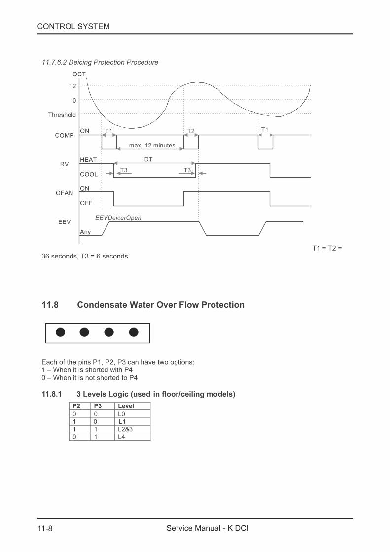
11.7.6.2 Deicing Protection Procedure
COMP
RV
OFAN
EEV
ON
HEAT
COOL
ON
OFF
EEVDeicerOpen
Any
T1 T2
T3 T3
T1
12
0
Threshold
max. 12 minutes
DT
OCT
T1 = T2 =36 seconds, T3 nds= 6 seco
11.8 Condensate Water Over Flow Protection
Each of the pins P1, P2, P3 can have two options:1 – When it is shorted with P40 – When it is not shorted to P4
11.8.1 3 Levels Logic (used in floor/ceiling models)
P2 P3 Level
0 0 L0
1 0 L1
1 1 L2 3&
0 1 L4
11-9
CONTROL SYSTEM
Service Manual - K DCI
Water Level
ANY
0
BLINK
NLOAD
OPER LED
LEVEL1
LEVEL 3
LEVEL4
NORMAL
ON
Pump OFF
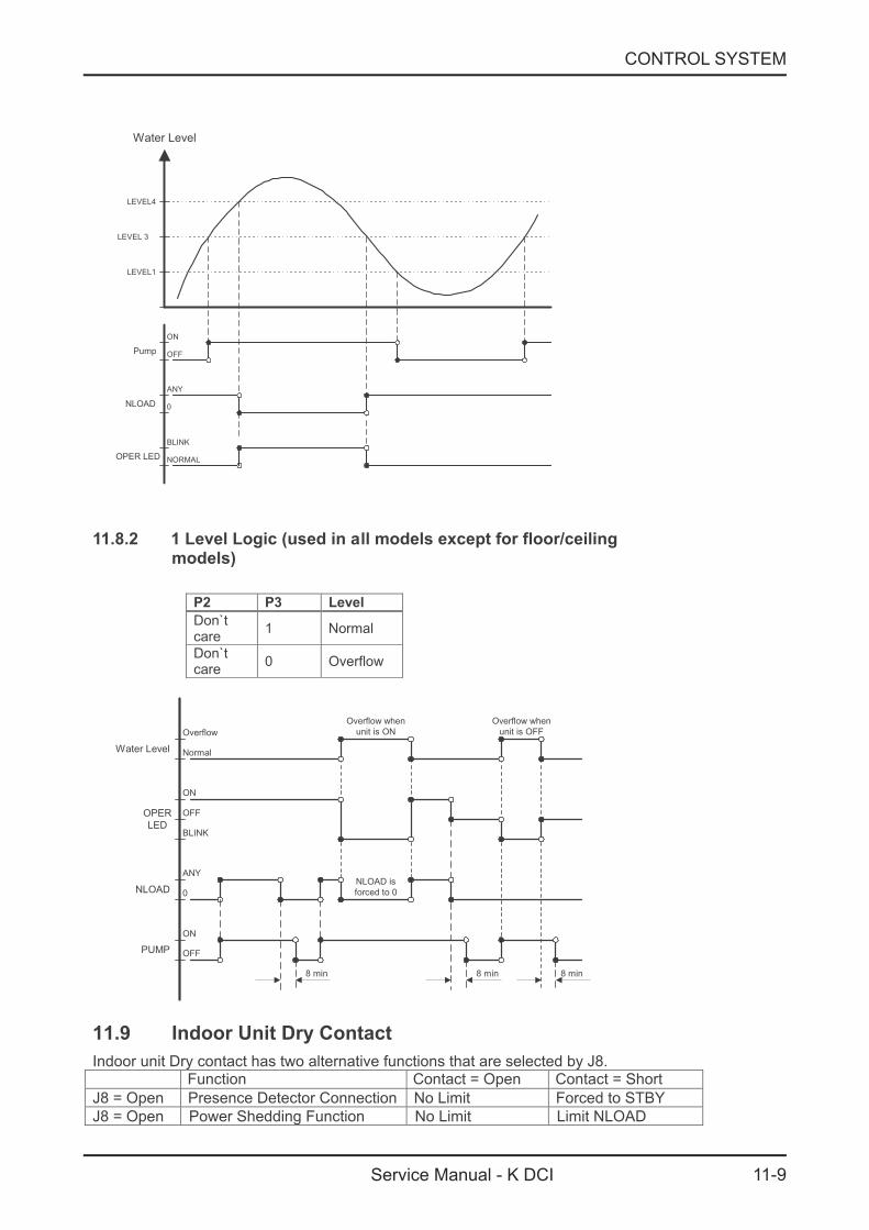
11.8.2 1 Level Logic (used in all models except for floor/ceiling
models)
P2 P3 Level
Don`tcare
1 Normal
Don`tcare
0 Overflow
ANY
0
ON
NLOAD
PUMP OFF
ON
OPER
LED
OFF
Overflow
Water Level Normal
BLINK
NLOAD is
forced to 0
8 min 8 min
Overflow when
unit is ON
Overflow when
unit is OFF
8 min
11.9 Indoor Unit Dry Contact
Indoor unit Dry contact has two alternative functions that are selected by J8.Function Contact = Open Contact = Short
J8 Presence Detector Connection No Limit Forced to STBY= Open
J8 Power Shedding Function No Limit Limit NLOAD= Open

11-10
CONTROL SYSTEM
Service Manual - K DCI
11.10 Operating the Unit from the Mode Button
Forced operation allows to start, stop and operate in Cooling or Heating, in pre-set temperatureaccording to the following table:
Forced operation Mode Pre-set Temperature
Cooling 200C
Heating 280C
11.11 On Unit Controls and Indicators
11.11.1 Indoor Unit Controller Controls and Indicators For All Models
Except for Floor/Ceiling model
STAND BYINDICATOR
Lights up when the Air Conditioner is connected to power and ready toreceive the R/C commands
OPERATION INDICATOR
Lights up during operation.Blinks for 300 msec., to announce that a R/C infrared signal hasbeen received and stored.Blinks continuously during protections (according to the relevant specsection).
TIMER INDICATOR Lights up during Timer and Sleep operation.
FILTER INDICATOR Lights up when Air Filter needs to be cleaned.
COOLING INDICATORLights up when system is switched to Cool Mode by using the ModeSwitch on the unit.
HEATING INDICATORLights up when system is switched Heat Mode by using the ModeSwitch on the unit.
Mode SWITCH(COOL/HEAT/OFF)
Every short pressing , the next operation mode is selected, in this order: SB → Cool Mode → Heat Mode → SB →In long pressing system enters diagnostic mode.
RESET / FILTERSWITCH
For short pressing:When Filter LED is on - turn off the FILTER INDICATOR after a cleanfilter has been reinstalled.When Filter LED is off able/disable the buzzer announcer, ifselected.

11-11
CONTROL SYSTEM
Service Manual - K DCI
11.11.2 Indoor Unit Controls and Indicators for LCD Display
STBY Cool Heat Auto Fan Dry
OFF SPT(1*)
OFF(2*)
OFF(2*) OFF(2*) OFF(2*) OFF(2*) OFF(2*) OFF(2*)
SPT(1*)
ON(2*)ON(2*) ON(2*) ON(2*) ON(2*)
SPT(1*)SPT(1*) SPT(1*) SPT(1*)
(Low)OFF
(Med)
OFF
(High)OFF
(Turbo)
OFF
(Auto)
OFF
UsersettingIFANspeed
UsersettingIFANspeed
UsersettingIFANspeed
UsersettingIFANspeed
UsersettingIFANspeed
Backlight(red) OFF OFF ON(3*) ON(3*)
ON(3*)
ON(3*)
ON(3*) ON(3*)
OFF
Backlight(green) OFF ON(3*) OFF
11-12
CONTROL SYSTEM
Service Manual - K DCI
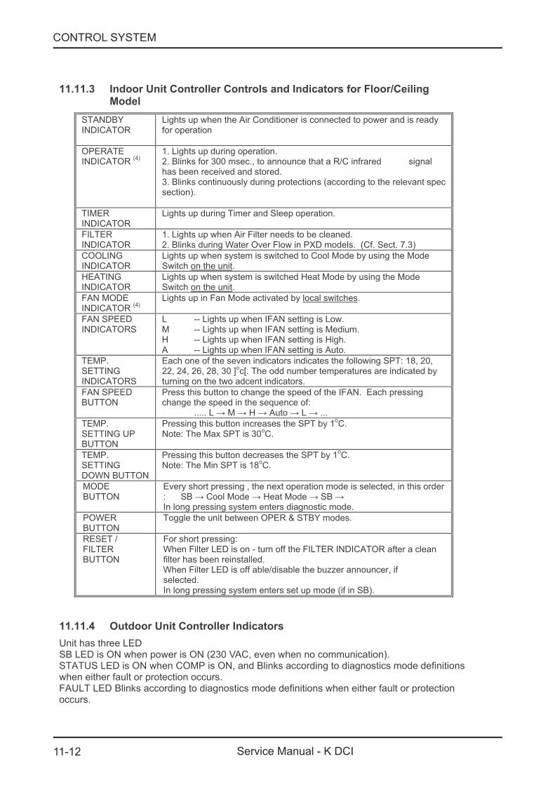
11.11.3 Indoor Unit Controller Controls and Indicators for Floor/Ceiling
Model
STANDBYINDICATOR
Lights up when the Air Conditioner is connected to power and is readyfor operation
OPERATEINDICATOR
(4)1. Lights up during operation.2. Blinks for 300 msec., to announce that a R/C infrared signalhas been received and stored.3. Blinks continuously during protections (according to the relevant specsection).
TIMERINDICATOR
Lights up during Timer and Sleep operation.
FILTERINDICATOR
1. Lights up when Air Filter needs to be cleaned.2. Blinks during Water Over Flow in PXD models. (Cf. Sect. 7.3)
COOLINGINDICATOR
Lights up when system is switched to Cool Mode by using the ModeSwitch on the unit.
HEATINGINDICATOR
Lights up when system is switched Heat Mode by using the ModeSwitch on the unit.
FAN MODEINDICATOR
(4)Lights up in Fan Mode activated by local switches.
FAN SPEEDINDICATORS
L -- Lights up when IFAN setting is Low.M -- Lights up when IFAN setting is Medium.H -- Lights up when IFAN setting is High.A -- Lights up when IFAN setting is Auto.
TEMP.SETTINGINDICATORS
Each one of the seven indicators indicates the following SPT: 18, 20,22, 24, 26, 28, 30 ]
oc[. The odd number temperatures are indicated by
turning on the two adcent indicators.
FAN SPEEDBUTTON
Press this button to change the speed of the IFAN. Each pressingchange the speed in the sequence of:
..... L → M → H → Auto → L → ...
TEMP.SETTING UPBUTTON
Pressing this button increases the SPT by 1oC.
Note: The Max SPT is 30oC.
TEMP.SETTINGDOWN BUTTON
Pressing this button decreases the SPT by 1oC.
Note: The Min SPT is 18oC.
MODEBUTTON
Every short pressing , the next operation mode is selected, in this order: SB → Cool Mode → Heat Mode → SB →In long pressing system enters diagnostic mode.
POWERBUTTON
Toggle the unit between OPER & STBY modes.
RESET /FILTERBUTTON
For short pressing:When Filter LED is on - turn off the FILTER INDICATOR after a cleanfilter has been reinstalled.When Filter LED is off able/disable the buzzer announcer, ifselected.In long pressing system enters set up mode (if in SB).
11.11.4 Outdoor Unit Controller Indicators
Unit has three LEDSB LED is ON when power is ON (230 VAC, even when no communication).STATUS LED is ON when COMP is ON, and Blinks according to diagnostics mode definitionswhen either fault or protection occurs.FAULT LED Blinks according to diagnostics mode definitions when either fault or protectionoccurs.
11-13
CONTROL SYSTEM
Service Manual - K DCI
11.1 . Indoor Unit Controller2 1
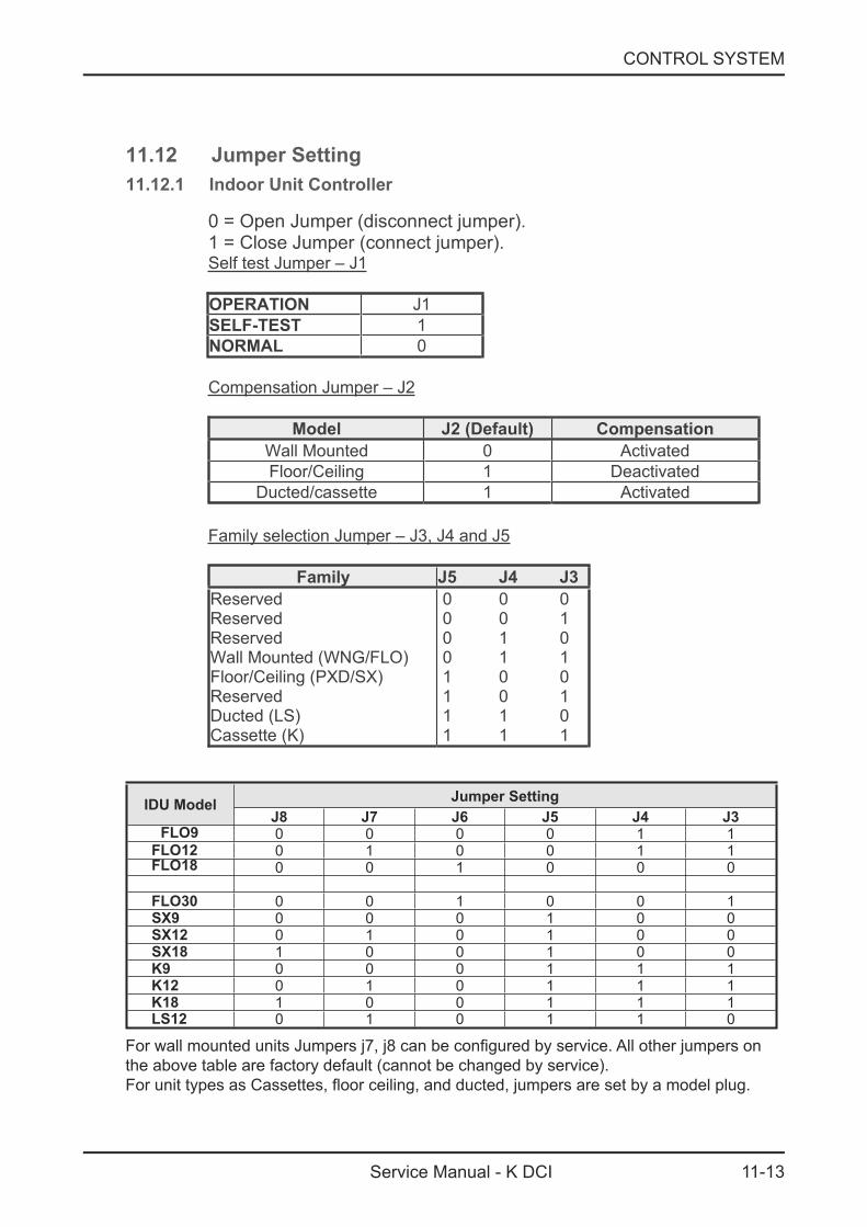
11.12 Jumper Setting
0 = Open Jumper (disconnect jumper). 1 = Close Jumper (connect jumper). Self test Jumper – J1
OPERATION J1SELF-TEST 1NORMAL 0
Compensation Jumper – J2
Model J2 (Default) Compensation Wall Mounted 0 Activated Floor/Ceiling 1 Deactivated
Ducted/cassette 1 Activated
Family selection Jumper – J3, J4 and J5
Family J5 J4 J3 Reserved Reserved Reserved Wall Mounted (WNG/FLO) Floor/Ceiling (PXD/SX) Reserved Ducted (LS) Cassette (K)
0 0 0 0 0 1 0 1 0 0 1 1 1 0 0 1 0 1 1 1 0 1 1 1
IDU Model Jumper SettingJ8 J7 J6 J5 J4 J30 0 0 0 1 10 1 0 0 1 10 0 1 0 0 0
0 0 1 0 0 10 0 0 1 0 00 1 0 1 0 01 0 0 1 0 00 0 0 1 1 10 1 0 1 1 11 0 0 1 1 10 1 0 1 1 0
For wall mounted units Jumpers j7, j8 can be configured by service. All other jumpers on the above table are factory default (cannot be changed by service). For unit types as Cassettes, floor ceiling, and ducted, jumpers are set by a model plug.
FLO9FLO12FLO18 FLO30SX9SX12SX18K9K12K18LS12
11-14
CONTROL SYSTEM
Service Manual - K DCI
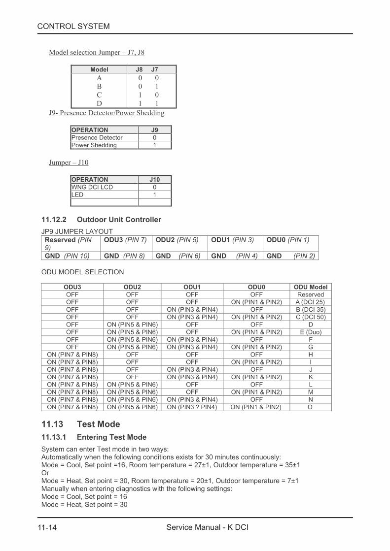
11.12.2 Outdoor Unit Controller
JP9 JUMPER LAYOUT
Reserved (PIN9)
ODU3 (PIN 7) ODU2 (PIN 5) ODU1 (PIN 3) ODU0 (PIN 1)
GND (PIN 10) GND (PIN 8) GND (PIN 6) GND (PIN 4) GND (PIN 2)
ODU MODEL SELECTION
ODU3 ODU2 ODU1 ODU0 ODU Model
OFF OFF OFF OFF Reserved
OFF OFF OFF ON (PIN1 & PIN2) A (DCI 25)
OFF OFF ON (PIN3 & PIN4) OFF B (DCI 35)
OFF OFF ON (PIN3 & PIN4) ON (PIN1 & PIN2) C (DCI 50)
OFF ON (PIN5 & PIN6) OFF OFF D
OFF ON (PIN5 & PIN6) OFF ON (PIN1 & PIN2) E (Duo)
OFF ON (PIN5 & PIN6) ON (PIN3 & PIN4) OFF F
OFF ON (PIN5 & PIN6) ON (PIN3 & PIN4) ON (PIN1 & PIN2) G
ON (PIN7 & PIN8) OFF OFF OFF H
ON (PIN7 & PIN8) OFF OFF ON (PIN1 & PIN2) I
ON (PIN7 & PIN8) OFF ON (PIN3 & PIN4) OFF J
ON (PIN7 & PIN8) OFF ON (PIN3 & PIN4) ON (PIN1 & PIN2) K
ON (PIN7 & PIN8) ON (PIN5 & PIN6) OFF OFF L
ON (PIN7 & PIN8) ON (PIN5 & PIN6) OFF ON (PIN1 & PIN2) M
ON (PIN7 & PIN8) ON (PIN5 & PIN6) ON (PIN3 & PIN4) OFF N
ON (PIN7 & PIN8) ON (PIN5 & PIN6) ON (PIN3 ? PIN4) ON (PIN1 & PIN2) O
11.13 Test Mode
11.13.1 Entering Test Mode
System can enter Test mode in two ways:Automatically when the following conditions exists for 30 minutes continuously:Mode l, Set point 16, Room temper= Coo = ature = 27±1, Outdoor temperature = 35±1OrMode = Heat, Set point = 30, Room temperature = 20±1, Outdoor temperature = 7±1Manually when entering diagnostics with the following settings:Mode = Cool, Set point = 16Mode = Heat, Set point = 30
Model selection Jumper – J7, J8
Model J8 J7 ABCD
0 0 0 1 1 0 1 1
J9- Presence Detector/Power Shedding
OPERATION J9 Presence Detector 0 Power Shedding 1
Jumper – J10
OPERATION J10 WNG DCI LCD 0 LED 1

11-15
CONTROL SYSTEM
Service Manual - K DCI
11.13.2 Unit Operation in Test Mode
In test mode, the unit will operate in fixed settings according to the indoor fan speed setting:
Indoor Fan Speed Setting Unit Setting
Low Minimum Capacity Setting
High Nominal Capacity Setting
Auto Maximum Capacity Setting
During test mode, protections are disabled, except for stop compressor status.
11.14 SW Parameters
11.14.1 Indoor Units SW Parameters
General Parameters for All Models:Parameters defining the indoor fan speed as a function of Indoor Coil temperature in heat mode (ICT):
ICTST Speed ICT to stop indoor fan 25ICTVLSpeed ICT to go down to very low speed 28ICTLSpeed ICT to start in very low speed 30ICTHSpeed ICT to start in increase speed from very low 32ICTTSpeed ICT to enable Turbo fan speed 40
Model Depended Parameters:
Parameter name Wall Mounted ModelsDCI 9 DCI 12
NLOAD limits as a function of selected indoor fan speedMaxNLOADIF1C 40 40MaxNLOADIF2C 53 53MaxNLOADIF3C 120 120MaxNLOADIF4C 127 127MaxNLOADIF5C 127 127
Indoor Fan speedsIFVLOWC 700 700IFLOWC 800 800IFMEDC 900 950IFHIGHC 1050 1100IFTURBOC 1150 1200IFVLOWH 700 700IFLOWH 800 850IFMEDH 950 1000IFHIGHH 1100 1150IFTURBOH 1200 1250
Nominal Compressor FrequencyNomLoadC 40 62NomLoadH 55 67
Parameter Name Cassette ModelsK 9 K 12 K 35S K 18
NLOAD limits as a function of selected indoor fan speedMaxNLOADIF1C 40 40 40 40MaxNLOADIF2C 53 56 56 60MaxNLOADIF3C 120 90 90 90MaxNLOADIF4C 127 90 90 90MaxNLOADIF5C 127 90 90 90
Nominal Compressor FrequencyNomLoadC 40 60 56 63NomLoadH 55 69 73 80
11-16
CONTROL SYSTEM
Service Manual - K DCI
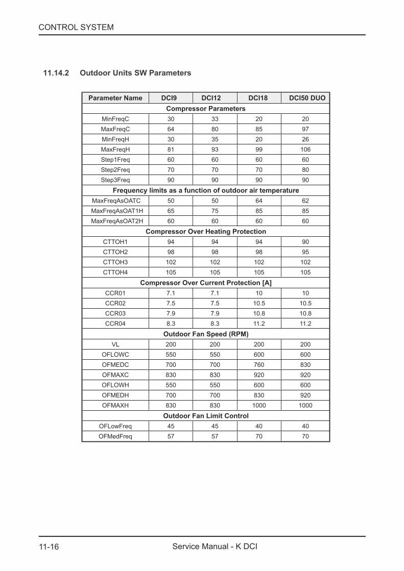
11.14.2 Outdoor Units SW Parameters
Parameter Name DCI9 DCI12 DCI18 DCI50 DUOCompressor Parameters
MinFreqC 30 33 20 20MaxFreqC 64 80 85 97MinFreqH 30 35 20 26MaxFreqH 81 93 99 106Step1Freq 60 60 60 60Step2Freq 70 70 70 80Step3Freq 90 90 90 90
Frequency limits as a function of outdoor air temperature MaxFreqAsOATC 50 50 64 62
MaxFreqAsOAT1H 65 75 85 85 MaxFreqAsOAT2H 60 60 60 60
Compressor Over Heating ProtectionCTTOH1 94 94 94 90CTTOH2 98 98 98 95CTTOH3 102 102 102 102CTTOH4 105 105 105 105
Compressor Over Current Protection [A]CCR01 7.1 7.1 10 10CCR02 7.5 7.5 10.5 10.5CCR03 7.9 7.9 10.8 10.8CCR04 8.3 8.3 11.2 11.2
Outdoor Fan Speed (RPM)VL 200 200 200 200
OFLOWC 550 550 600 600OFMEDC 700 700 760 830OFMAXC 830 830 920 920OFLOWH 550 550 600 600OFMEDH 700 700 830 920OFMAXH 830 830 1000 1000
Outdoor Fan Limit ControlOFLowFreq 45 45 40 40OFMedFreq 57 57 70 70
12-1
TROUBLESHOOTING
Service Manual - K DCI
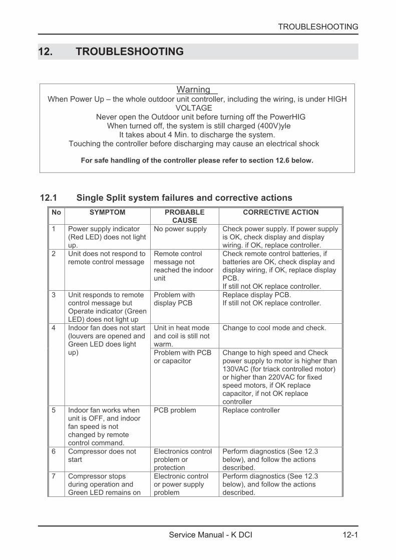
12. TROUBLESHOOTING
WarningWhen Power Up – the whole outdoor unit controller, including the wiring, is under HIGH
VOLTAGENever open the Outdoor unit before turning off the PowerHIG
When turned off, the system is still charged (400V)yleIt takes about 4 Min. to discharge the system.
Touching the controller before discharging may cause an electrical shock
For safe handling of the controller please refer to section 12.6 below.
12.1 Single Split system failures and corrective actions
No SYMPTOM PROBABLE
CAUSE
CORRECTIVE ACTION
1 Power supply indicator(Red LED) does not lightup.
No power supply Check power supply. If power supplyis OK, check display and displaywiring. if OK, replace controller.
2 Unit does not respond toremote control message
Remote controlmessage notreached the indoorunit
Check remote control batteries, ifbatteries are OK, check display anddisplay wiring, if OK, replace displayPCB.If still not OK replace controller.
3 Unit responds to remotecontrol message butOperate indicator (GreenLED) does not light up
Problem withdisplay PCB
Replace display PCB.If still not OK replace controller.
Unit in heat modeand coil is still notwarm.
Change to cool mode and check.4 Indoor fan does not start(louvers are opened andGreen LED does lightup) Problem with PCB
or capacitorChange to high speed and Checkpower supply to motor is higher than130VAC (for triack controlled motor)or higher than 220VAC for fixedspeed motors, if OK replacecapacitor, if not OK replacecontroller
5 Indoor fan works whenunit is OFF, and indoorfan speed is notchanged by remotecontrol command.
PCB problem Replace controller
6 Compressor does notstart
Electronics controlproblem orprotection
Perform diagnostics (See 12.3below), and follow the actionsdescribed.
7 Compressor stopsduring operation andGreen LED remains on
Electronic controlor power supplyproblem
Perform diagnostics (See 12.3below), and follow the actionsdescribed.
12-2
TROUBLESHOOTING
Service Manual - K DCI
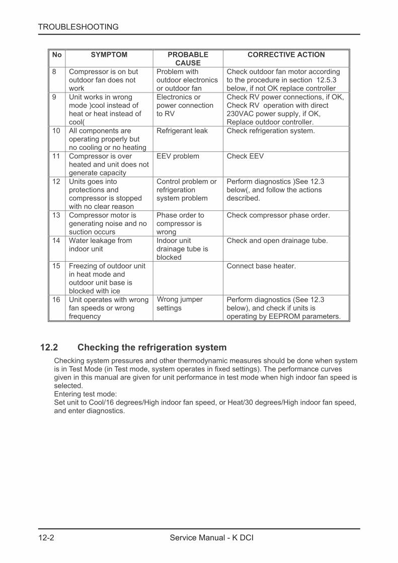
No SYMPTOM PROBABLE
CAUSE
CORRECTIVE ACTION
8 Compressor is on butoutdoor fan does notwork
Problem withoutdoor electronicsor outdoor fan
Check outdoor fan motor accordingto the procedure in section 12.5.3below, if not OK replace controller
9 Unit works in wrongmode )cool instead ofheat or heat instead ofcool(
Electronics orpower connectionto RV
Check RV power connections, if OK,Check RV operation with direct230VAC power supply, if OK,Replace outdoor controller.
10 All components areoperating properly butno cooling or no heating
Refrigerant leak Check refrigeration system.
11 Compressor is overheated and unit does notgenerate capacity
EEV problem Check EEV
12 Units goes intoprotections andcompressor is stoppedwith no clear reason
Control problem orrefrigerationsystem problem
Perform diagnostics )See 12.3below(, and follow the actionsdescribed.
13 Compressor motor isgenerating noise and nosuction occurs
Phase order tocompressor iswrong
Check compressor phase order.
14 Water leakage fromindoor unit
Indoor unitdrainage tube isblocked
Check and open drainage tube.
15 Freezing of outdoor unitin heat mode andoutdoor unit base isblocked with ice
Connect base heater.
16 Unit operates with wrongfan speeds or wrongfrequency
Wrong umperj
settingsPerform diagnostics (See 12.3below), and check if units isoperating by EEPROM parameters.
12.2 Checking the refrigeration system
Checking system pressures and other thermodynamic measures should be done when systemis in Test Mode (in Test mode, system operates in fixed settings). The performance curvesgiven in this manual are given for unit performance in test mode when high indoor fan speed isselected.Entering test mode:Set unit to Cool/16 degrees/High indoor fan speed, or Heat/30 degrees/High indoor fan speed,and enter diagnostics.
12-3
TROUBLESHOOTING
Service Manual - K DCI
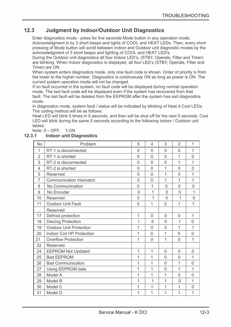
12.3 Judgment by Indoor/Outdoor Unit Diagnostics
Enter diagnostics mode - press for five seconds Mode button in any operation mode.Acknowledgment is by 3 short beeps and lights of COOL and HEAT LEDs. Then, every shortpressing of Mode button will scroll between Indoor and Outdoor unit diagnostic modes by theacknowledgment of 3 short beeps and lighting of COOL and HEAT LED s.'During the Outdoor unit diagnostics all four Indoor LED’s, (STBY, Operate, Filter and Timer)are blinking. When Indoor diagnostics is displayed, all four LED’s (STBY, Operate, Filter andTimer) are ON.When system enters diagnostics mode, only one fault code is shown. Order of priority is fromthe lower to the higher number. Diagnostics is continuously ON as long as power is ON. Thecurrent system operation mode will not be changed.If no fault occurred in the system, no fault code will be displayed during normal operationmode. The last fault code will be displayed even if the system has recovered from thatfault. The last fault will be deleted from the EEPROM after the system has exit diagnosticsmode.In diagnostics mode, system fault / status will be indicated by blinking of Heat d Cool LEDs.The coding method will be as follows:Heat LED will blink 5 times in 5 seconds, and then will be shut off for the next 5 seconds. CoolLED will blink during the same 5 seconds according to the following Indoor / Outdoor unittables:Note: 0 – OFF, 1-ON
12.3.1 Indoor unit Diagnostics
No Problem 5 4 3 2 1
1 RT-1 is disconnected 0 0 0 0 1
2 RT-1 is shorted 0 0 0 1 0
3 RT-2 is disconnected 0 0 0 1 1
4 RT-2 is shorted 0 0 1 0 0
5 Reserved 0 0 1 0 1
7 Communication mismatch 0 0 1 1 1
10 Reserved 0 1 0 1 0
11 Outdoor Unit Fault 0 1 0 1 1
17 Defrost protection 1 0 0 0 1
19 Outdoor Unit Protection 1 0 0 1 1
20 Indoor Coil HP Protection 1 0 1 0 0
21 Overflow Protection 1 0 1 0 1
22 Reserved
24 EEPROM Not Updated 1 1 0 0 0
25 Bad EEPROM 1 1 0 0 1
26 Bad Communication 1 1 0 1 0
27 Using EEPROM data 1 1 0 1 1
28 Model A 1 1 1 0 0
29
18
8 No Communication 0 1 0 0 0
No Encoder 0 1 0 0 19
... Reserved
30 Model C 1 1 1 1 0
31 Model D 1 1 1 1 1
Model B 1 1 1 0 1
Deicing Protection 1 0 0 1 0
12-4
TROUBLESHOOTING
Service Manual - K DCI
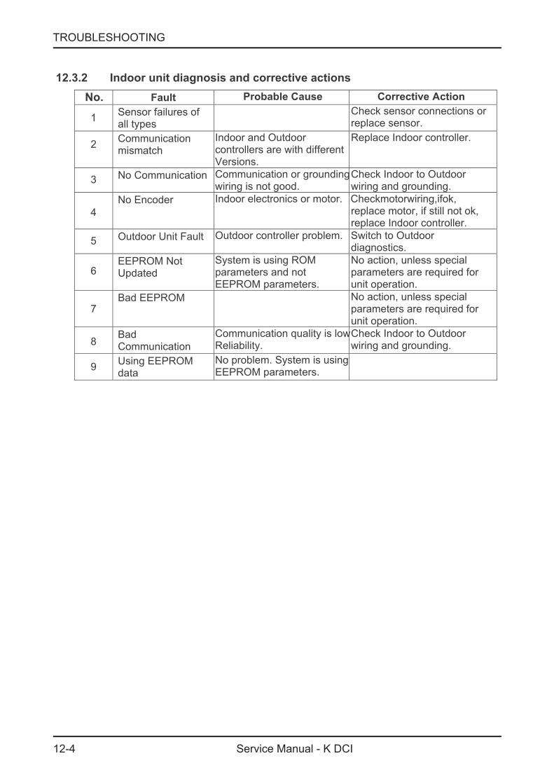
12.3.2 Indoor unit diagnosis and corrective actions
No. Fault Probable Cause Corrective Action
1Sensor failures ofall types
Check sensor connections orreplace sensor.
2Communicationmismatch
Indoor and Outdoorcontrollers are with differentVersions.
Replace Indoor controller.
3 No Communication Communication or groundingwiring is not good.
Check Indoor to Outdoorwiring and grounding.
4
No Encoder Indoor electronics or motor Checkmotorwiring,ifok,.replace motor, if still not ok,replace Indoor controller.
5 Outdoor Unit Fault Outdoor controller problem Switch to Outdoor.diagnostics.
6EEPROM NotUpdated
System is using ROMparameters and notEEPROM parameters.
No action, unless specialparameters are required forunit operation.
7Bad EEPROM No action, unless special
parameters are required forunit operation.
8BadCommunication
Communication quality is lowReliability.
Check Indoor to Outdoorwiring and grounding.
9Using EEPROMdata
No problem. System is usingEEPROM parameters.

12-5
TROUBLESHOOTING
Service Manual - K DCI
No Problem 5 4 3 2 1 1 OCT is disconnected 0 0 0 0 1 2 OCT is shorted 0 0 0 1 0 3 CTT is disconnected 0 0 0 1 1 4 CTT is shorted 0 0 1 0 0 5 HST is disconnected (when enabled) 0 0 1 0 1 6 HST is shorted (when enabled) 0 0 1 1 0 7 OAT is disconnected (when enabled) 0 0 1 1 1 8 OAT is shorted (when enabled) 0 1 0 0 0 9 TSUC is disconnected (when enabled) 0 1 0 0 1
10 TSUC is shorted (when enabled) 0 1 0 1 0 11 IPM Fault 0 1 0 1 1 12 Bad EEPROM 0 1 1 0 0 13 DC under voltage 0 1 1 0 1 14 DC over voltage 0 1 1 1 0 15 AC under voltage 0 1 1 1 1 16 IDU/ODU Communication mismatch 1 0 0 0 0 17 No Communication 1 0 0 0 1 18 Reserved 1 0 0 1 0 20 Heat sink Over Heating 1 0 1 0 0 21 Deicing 1 0 1 0 1 22 Compressor Over Heating 1 0 1 1 0 23 Compressor Over Current 1 0 1 1 1 24 No OFAN Feedback 1 1 0 0 0 25 OFAN locked 1 1 0 0 1 26 Compressor Lock 1 1 0 1 0 27 Bad Communication 1 1 0 1 1
1 - ON, 0 - OFFOnly one code is shown. Order of priorety is 1-24. Diagnostics is continuously ON as long power is on.
12.3.3 Outdoor Unit Diagnostics
12-6
TROUBLESHOOTING
Service Manual - K DCI
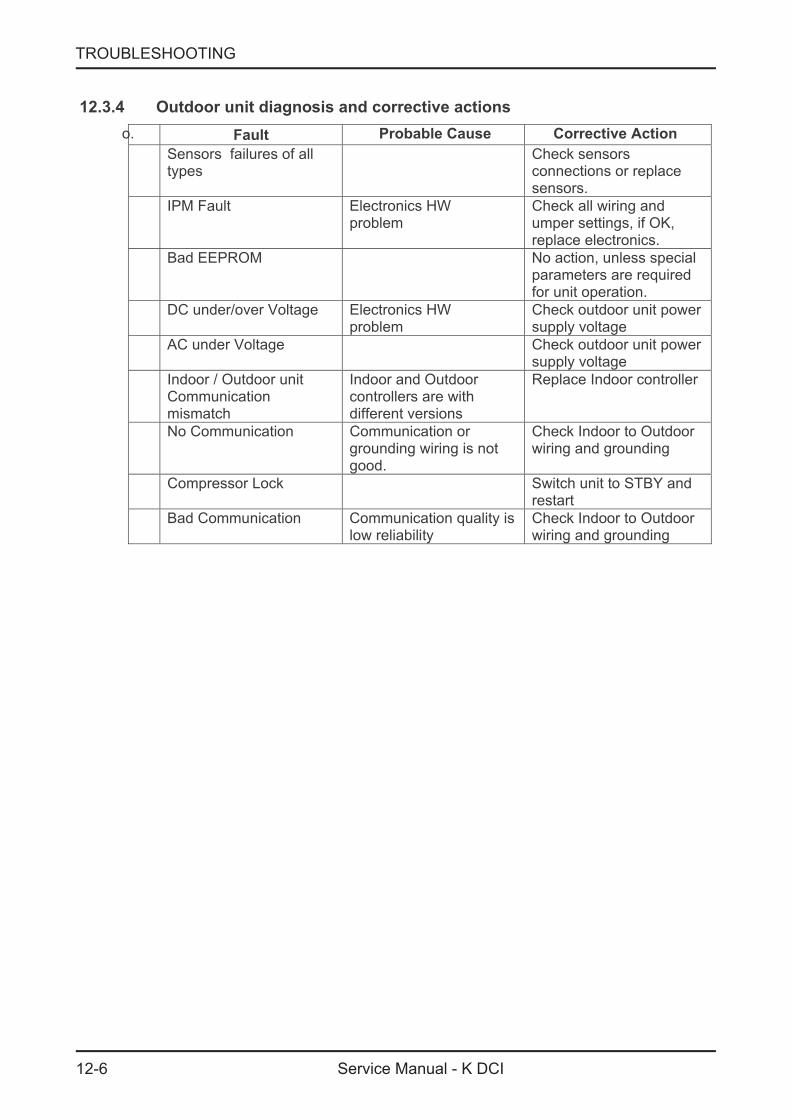
12.3.4 Outdoor unit diagnosis and corrective actions
o. Fault Probable Cause Corrective Action
Sensors failures of alltypes
Check sensorsconnections or replacesensors.
IPM Fault Electronics HWproblem
Check all wiring andumper settings, if OK,replace electronics.
Bad EEPROM No action, unless specialparameters are requiredfor unit operation.
DC under/over Voltage Electronics HWproblem
Check outdoor unit powersupply voltage
AC under Voltage Check outdoor unit powersupply voltage
Indoor / Outdoor unitCommunicationmismatch
Indoor and Outdoorcontrollers are withdifferent versions
Replace Indoor controller
No Communication Communication orgrounding wiring is notgood.
Check Indoor to Outdoorwiring and grounding
Compressor Lock Switch unit to STBY andrestart
Bad Communication Communication quality islow reliability
Check Indoor to Outdoorwiring and grounding

12-7
TROUBLESHOOTING
Service Manual - K DCI
12.4 Judgment by MegaTool
MegaTool is a special tool to monitor the system states.Using MegaTool requires:
• A computer with RS232C port.
• A connection wire for MegaTool.
• A special MegaTool software.Use MegaTool according to following procedure:
• Setup MegaTool software: copy the software to the computer.
• Connect RS232C port in computer with MegaTool port in Indoor/Outdoor unitcontroller by the connection wire.
• Run the software and choose the COM port, you can monitor the A/C system statein monitor tab.
12.5 Simple procedures for checking the Main Parts
12.5.1 Checking Mains Voltage.
Confirm that the Mains voltage is between 198 and 264 VAC. If Mains voltage is out of this
range, abnormal operation of the system is expected. If in range check the Power (Circuit)Breaker and look for broken or loosed cable lugs or wiring mistake(s).
12.5.2 Checking Power Input.
If Indoor unit power LED is unlighted, power down the system and check the fuse of the Indoorunit. If the fuse is OK replace the Indoor unit controller. If the fuse has blown, replace the fuseand power up again.Checking Power Input procedure for the Outdoor unit is the same as with the Indoor unit.
12.5.3 Checking the Outdoor Fan Motor.
Enter Test Mode (where the OFAN speed is high)Check the voltage between lead wires according to the normal value as following:
• Between red wire and black wire: 310VDC +/- 20V
• Between orange wire and black wire: 15VDC +/- 1V
• Between yellow wire and black wire: 2-6VDC
12.5.4 Checking the Compressor.
The compressor is brushless permanence magnetic DC motor. Three coil resistance issame. Check the resistance between three poles. The normal value should be below 0.5ohm (TBD).
12.5.5 Checking the Reverse Valve (RV).
Running in heating mode, check the voltage between two pins of reverse valveconnector, normal voltage is 220VAC.
12.5.6 Checking the electrical expansion valve (EEV).
The EEV has two parts, drive part and valve. The drive part is a step motorthe valve. Check the drive voltage (12VDC). When Outdoor unit is power on, EEV shallrun and have click and vibration.
12-8
TROUBLESHOOTING
Service Manual - K DCI
12.6 Precaution, Advise and Notice Items
12.6.1 High voltage in Outdoor unit controller.
Whole controller, including the wires that are connected to the Outdoor unit controller mayhave the potential hazard voltage when power is on. Touching the Outdoor unit controllermay cause an electrical shock.Advise: Don naked lead wire and don t insert finger, conductor or anything' 't touch the
else into the controller when power is on.
12.6.2 Charged Capacitors
Three large-capacity electrolytic capacitors are used in the Outdoor unit controller.Therefore, charging voltage (380VDC) remains after power down. Discharging takesabout four minutes after power is off. Touching the Outdoor unit controller beforedischarging may cause an electrical shock.
12.6.3 Additional advises
• When disassemble the controller or the front panel, turn off the power supply.
• When connecting or disconnecting the connectors on the PCB, hold the whole housing,dont pull the wire.
• There are sharp fringes and sting on shell. Use gloves when disassemble the A/Cunits.

With a concern for a constant improvement, our products can be modified without notice. Photos non contractual.
A.C.E MarketingFRANCE :1 bis,Avenue du 8 Mai 1945Saint-Quentin-en-Yvelines78284 GUYANCOURT Cedex Tél. 33 1 39 44 78 00 Fax 33 1 39 44 11 55 www.airwell.com
1 bis,Avenue du 8 Mai 1945Saint-Quentin-en-Yvelines78284 GUYANCOURT Cedex