TSDW Nies Optimum RF stabilization NTM large tokamaks
41
Richard Nies, Allan H. Reiman, Nathaniel J. Fisch Princeton Plasma Physics Laboratory, Princeton University Acknowledgements: Rob La Haye, Francesco Volpe Theory and Simulation of Disruptions Workshop, PPPL/IAEA, July 22nd 2021 Optimum RF stabilization of NTMs in large tokamaks https://arxiv.org/abs/2106.06581
Transcript of TSDW Nies Optimum RF stabilization NTM large tokamaks
Richard Nies, Allan H. Reiman, Nathaniel J. Fisch
Princeton Plasma Physics Laboratory, Princeton University
Acknowledgements: Rob La Haye, Francesco Volpe
Theory and Simulation of Disruptions Workshop, PPPL/IAEA, July 22nd 2021
Optimum RF stabilization of NTMs in
large tokamaks
https://arxiv.org/abs/2106.06581

Why stabilize Neoclassical Tearing Modes (NTMs)?
Degrade confinement and cause disruptions.
Typical NTM Life Cycle:
Rotate with plasma when born, then brake until they lock in lab frame.
How to stabilize NTMs?
Drive current at island O-point using RF.
When to stabilize NTMs?
In present-day devices: locking occurs at large width, quickly followed by disruption stabilize during rotating phase. Focus of almost all experimental and theoretical studies.
⇒
2
Motivation
Is this the best strategy for future larger devices?
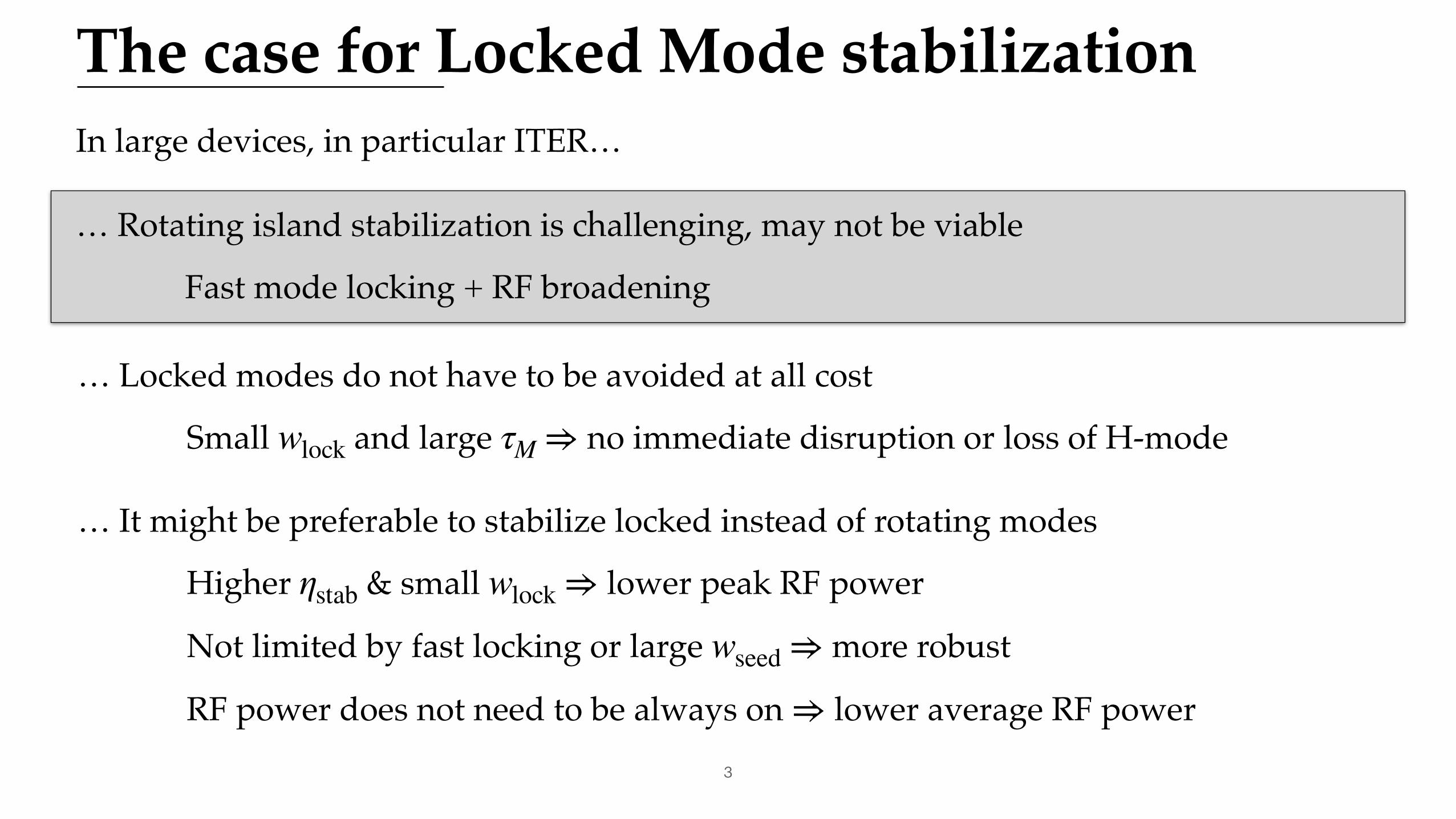
In large devices, in particular ITER…
… Rotating island stabilization is challenging, may not be viable
Fast mode locking + RF broadening
3
The case for Locked Mode stabilization
… Locked modes do not have to be avoided at all cost
Small and large no immediate disruption or loss of H-modewlock τM ⇒
… It might be preferable to stabilize locked instead of rotating modes
Higher & small lower peak RF power
Not limited by fast locking or large more robust
RF power does not need to be always on lower average RF power
ηstab wlock ⇒
wseed ⇒
⇒

Challenge 1: fast mode lockingHigh plasma inertia + small torque
small rotation - ITER: kHz
fast locking - ITER (with blanket [1]):
s with
Must stabilize island below [1],
above which island slows and locks.
⇒ f2/1 ∼ 0.42
⇒
tlock ∼ 1.7 wlock ∼ 4.5 % a
wcrit ∼ 2 − 3 % a
[1] La Haye et al. 2017[3] Snicker et
Make use of fast locking: stabilize small locked mode4
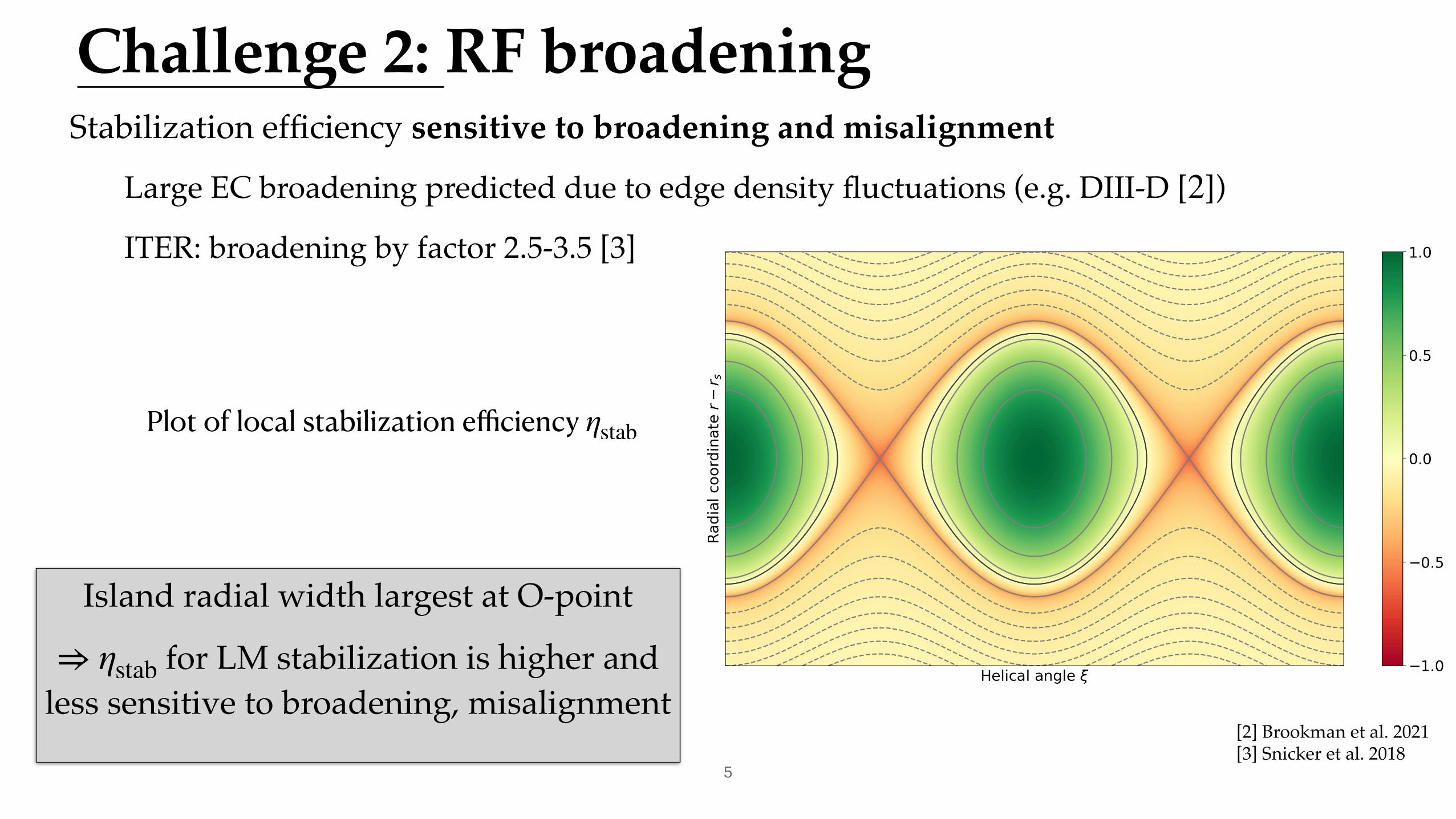
Island radial width largest at O-point
for LM stabilization is higher and less sensitive to broadening, misalignment⇒ ηstab
Plot of local stabilization efficiency ηstab
Challenge 2: RF broadening
[2] Brookman et al. 2021[3] Snicker et al. 2018
Stabilization efficiency sensitive to broadening and misalignment
Large EC broadening predicted due to edge density fluctuations (e.g. DIII-D [ ])
ITER: broadening by factor 2.5-3.5 [3]
2
5
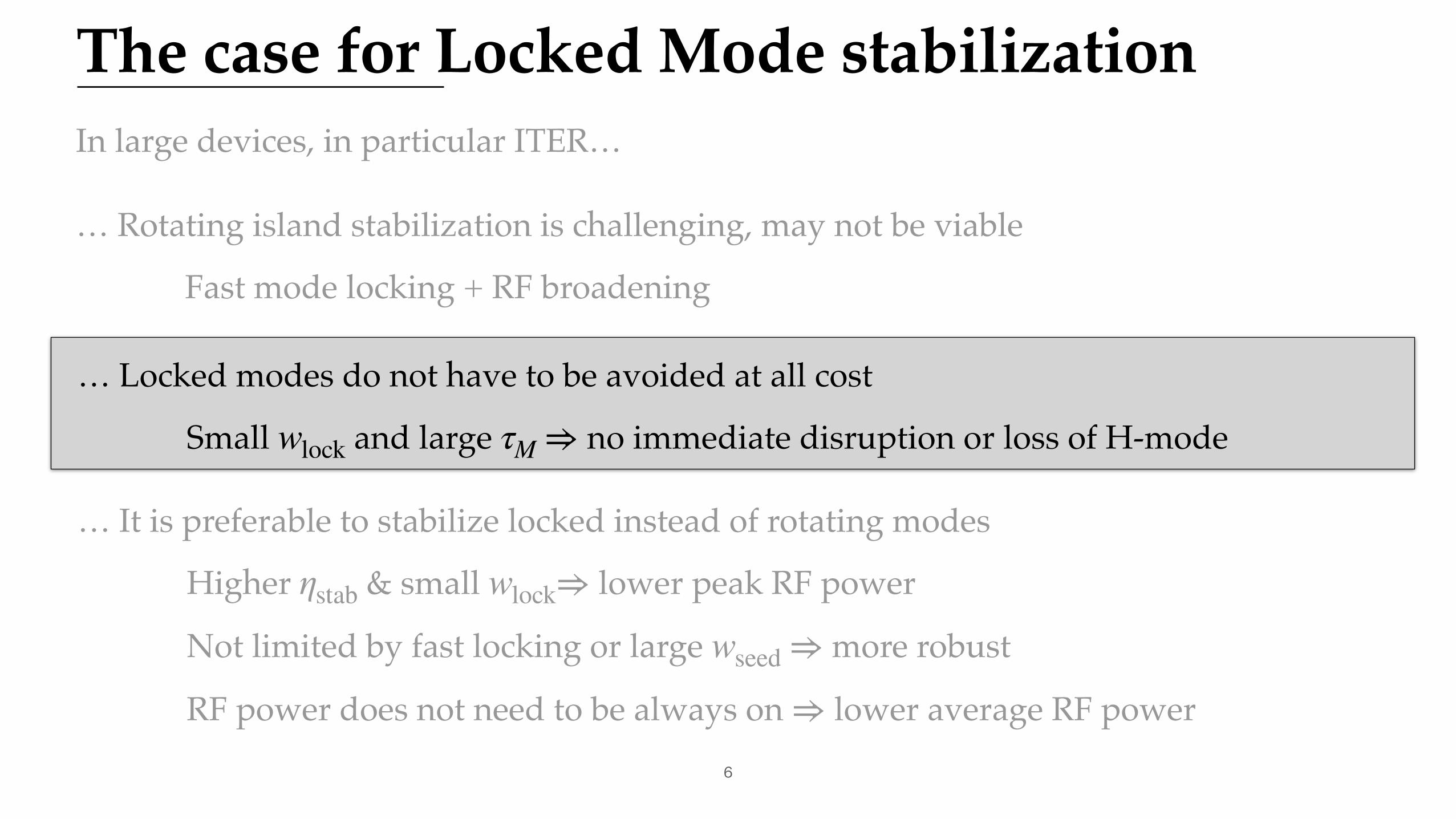
In large devices, in particular ITER…
… Rotating island stabilization is challenging, may not be viable
Fast mode locking + RF broadening
6
The case for Locked Mode stabilization
… Locked modes do not have to be avoided at all cost
Small and large no immediate disruption or loss of H-modewlock τM ⇒
… It is preferable to stabilize locked instead of rotating modes
Higher & small lower peak RF power
Not limited by fast locking or large more robust
RF power does not need to be always on lower average RF power
ηstab wlock⇒
wseed ⇒
⇒
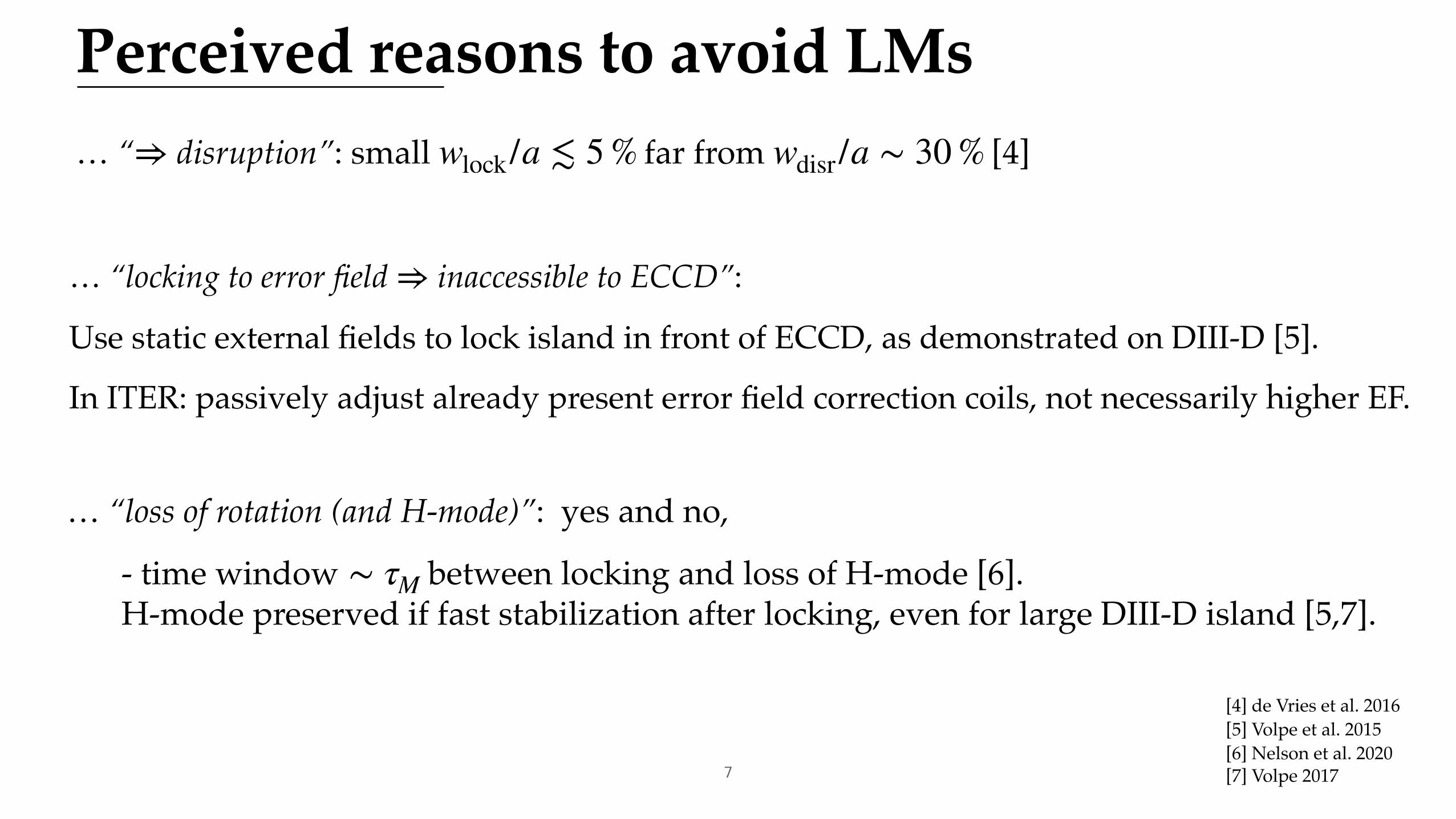
Perceived reasons to avoid LMs… “ disruption”: small far from [4]⇒ wlock/a ≲ 5 % wdisr /a ∼ 30 %
[4] de Vries et al. 2016[5] Volpe et al. 2015
… “locking to error field inaccessible to ECCD”:
Use static external fields to lock island in front of ECCD, as demonstrated on DIII-D [5].
In ITER: passively adjust already present error field correction coils, not necessarily higher EF.
⇒
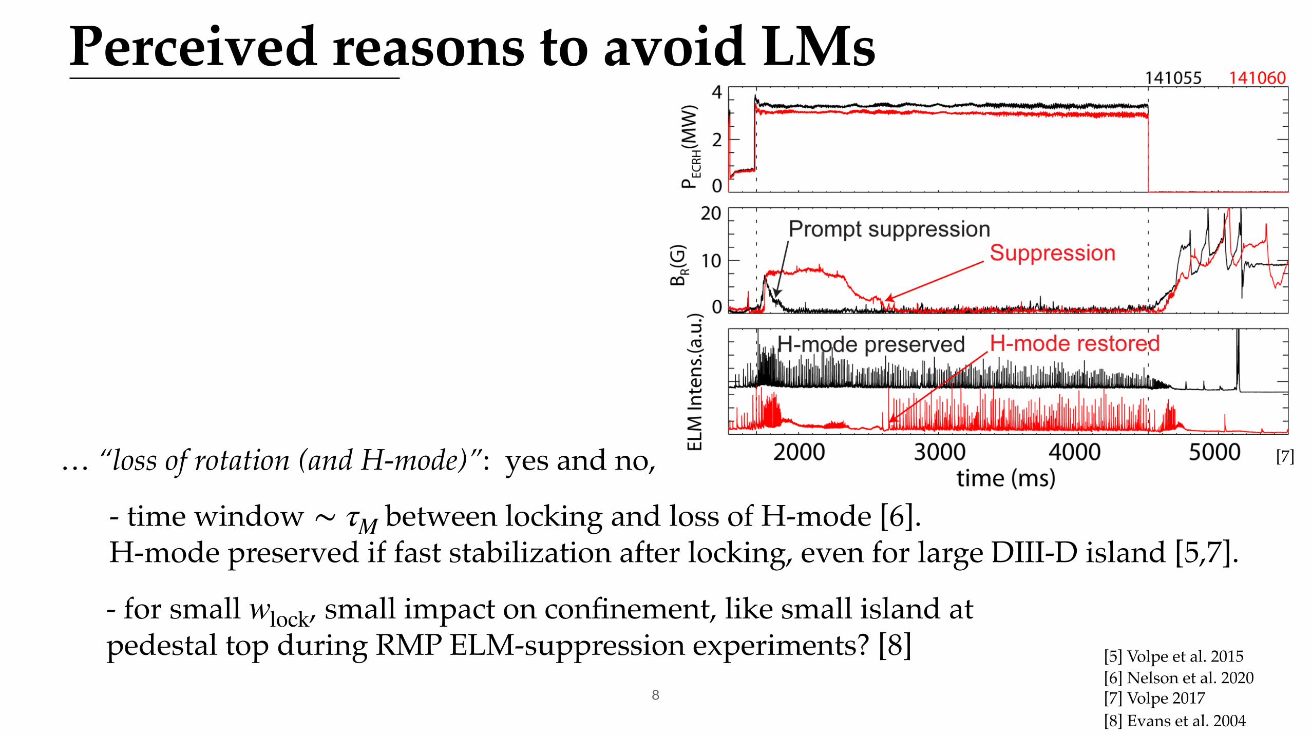
… “loss of rotation (and H-mode)”: yes and no,
- time window between locking and loss of H-mode [6]. H-mode preserved if fast stabilization after locking, even for large DIII-D island [5,7].
∼ τM
[6] Nelson et al. 2020[7] Volpe 20177
Perceived reasons to avoid LMs
[5] Volpe et al. 2015
… “loss of rotation (and H-mode)”: yes and no,
- time window between locking and loss of H-mode [6]. H-mode preserved if fast stabilization after locking, even for large DIII-D island [5,7].
∼ τM
[6] Nelson et al. 2020[7] Volpe 20178
[7]
[8] Evans et al. 2004
- for small , small impact on confinement, like small island at pedestal top during RMP ELM-suppression experiments? [8]
wlock

9
The case for Locked Mode stabilization
… It might be preferable to stabilize locked instead of rotating modes
Higher & small lower peak RF power
Not limited by fast locking or large more robust
RF power does not need to be always on lower average RF power
ηstab wlock ⇒
wseed ⇒
⇒
Hard to avoid LMs in large tokamaks like ITER…… but small LMs are tolerable …
Prepare LM Stabilization strategy, at least as back-up.
Can even consider stabilization of large LMs to further reduce disruptivity: see A. Reiman talk Friday 11:10
⇒

Island evolutionGeneralized Rutherford Equation
Torque Equation
and to resolve dependencies of EF terms and .
0.82τr
rs
dwdt
= rs [Δ′ 0−Δ′ 0,wall(ω)]Classical [1,9]
+ 2m ( wvac
w )2
cos(ϕ − ϕEF)
Error field / RMP [10]
+ a2jBS
j∥Lq
23w
−3w2
ib
w3
Bootstrap andpolarisation [1]
−3π3/2
4wdep
w2dep
w2ηNTMηaux
Current drive [11]
dωdt
=ω0(τM /τM0) − ω
τM
Viscous [1]
−1
τ2A0 ( w
a )3 C1
mωτw
(ωτw)2 + 1
Resistive wall [1,9]
+m2
256 ( aLq )
2
( wvac
w )2
sin(ϕ − ϕEF)
Error field / RMP [10]
·ϕ = ω ϕ ηaux[1] La Haye et al. 2017[9] Nave & Wesson 1990[10] Fitzpatrick 1993[11] De Lazzari & Westerhof 2009[12] van den Brand et al. 2012[13] La Haye et al. 2006
Extension of previous work in [2,10,11]. More details on each term in Appendix.10
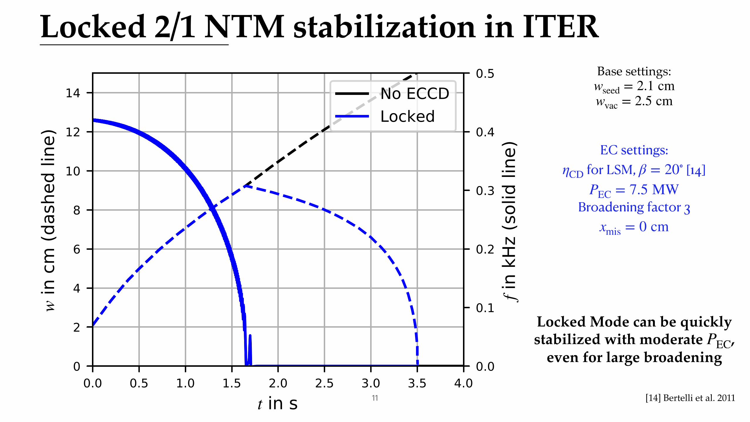
Locked 2/1 NTM stabilization in ITERBase settings:
wseed = 2.1 cmwvac = 2.5 cm
11
EC settings: for LSM, [14]
Broadening factor 3
ηCD β = 20∘
PEC = 7.5 MW
xmis = 0 cm
[14] Bertelli et al. 2011
Locked Mode can be quicklystabilized with moderate ,
even for large broadeningPEC
12
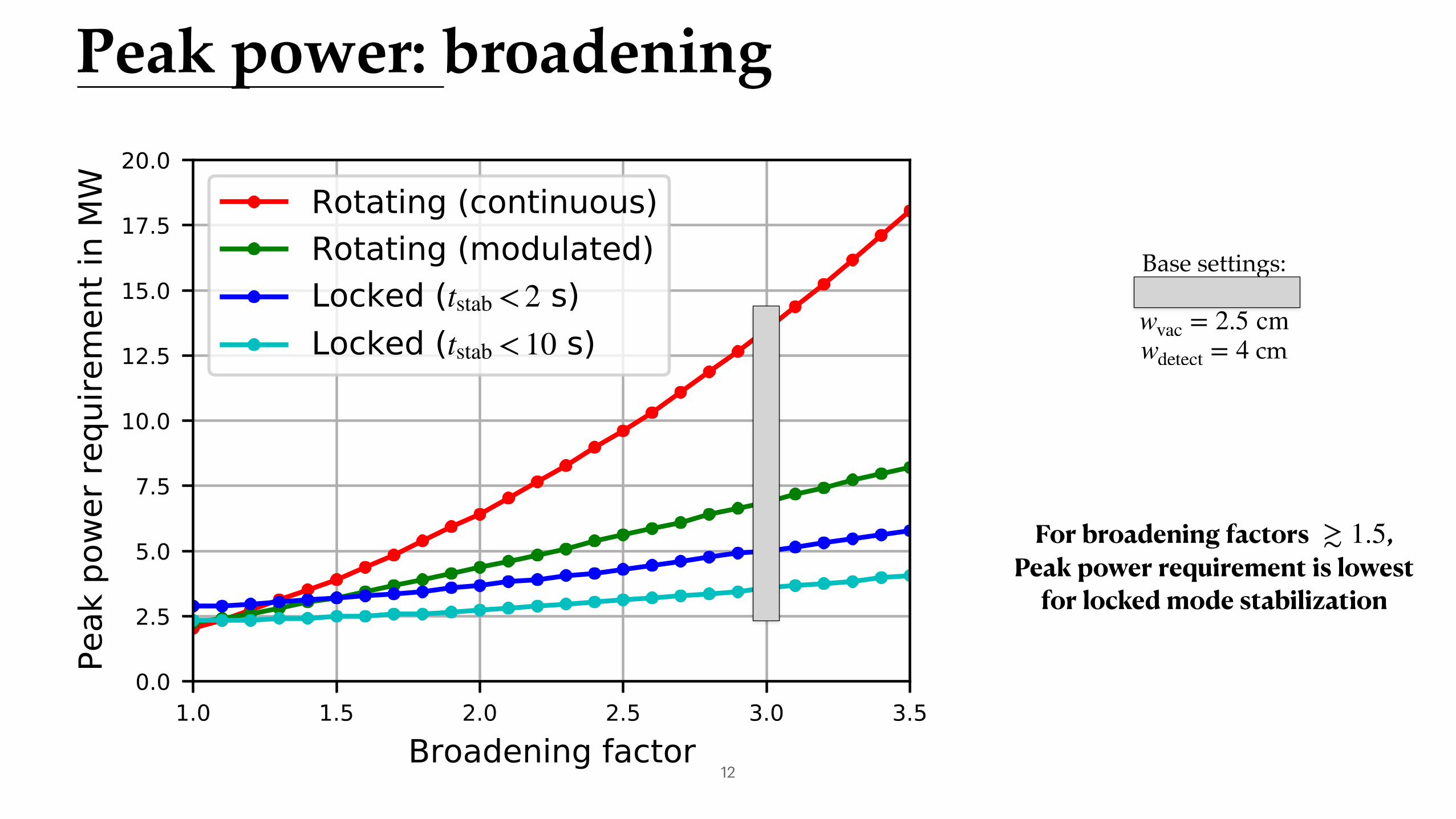
Base settings:
cm
wseed = 2.1 cmwvac = 2.5 cmwdetect = 4
For broadening factors , Peak power requirement is lowest
for locked mode stabilization
≳ 1.5
Peak power: broadening
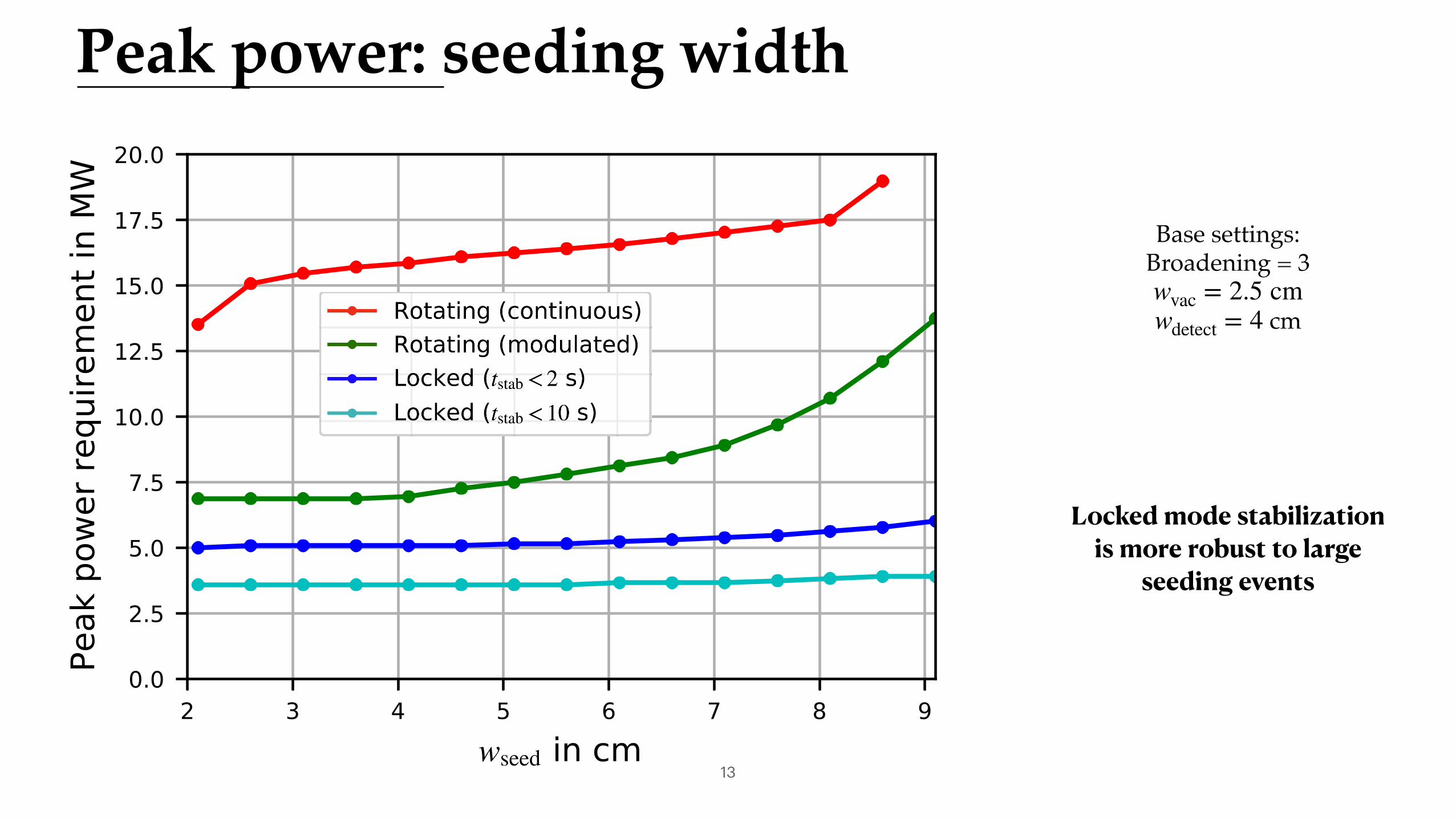
Peak power: seeding width
13
Locked mode stabilization is more robust to large
seeding events
Base settings:Broadening = 3
cmwvac = 2.5 cmwdetect = 4
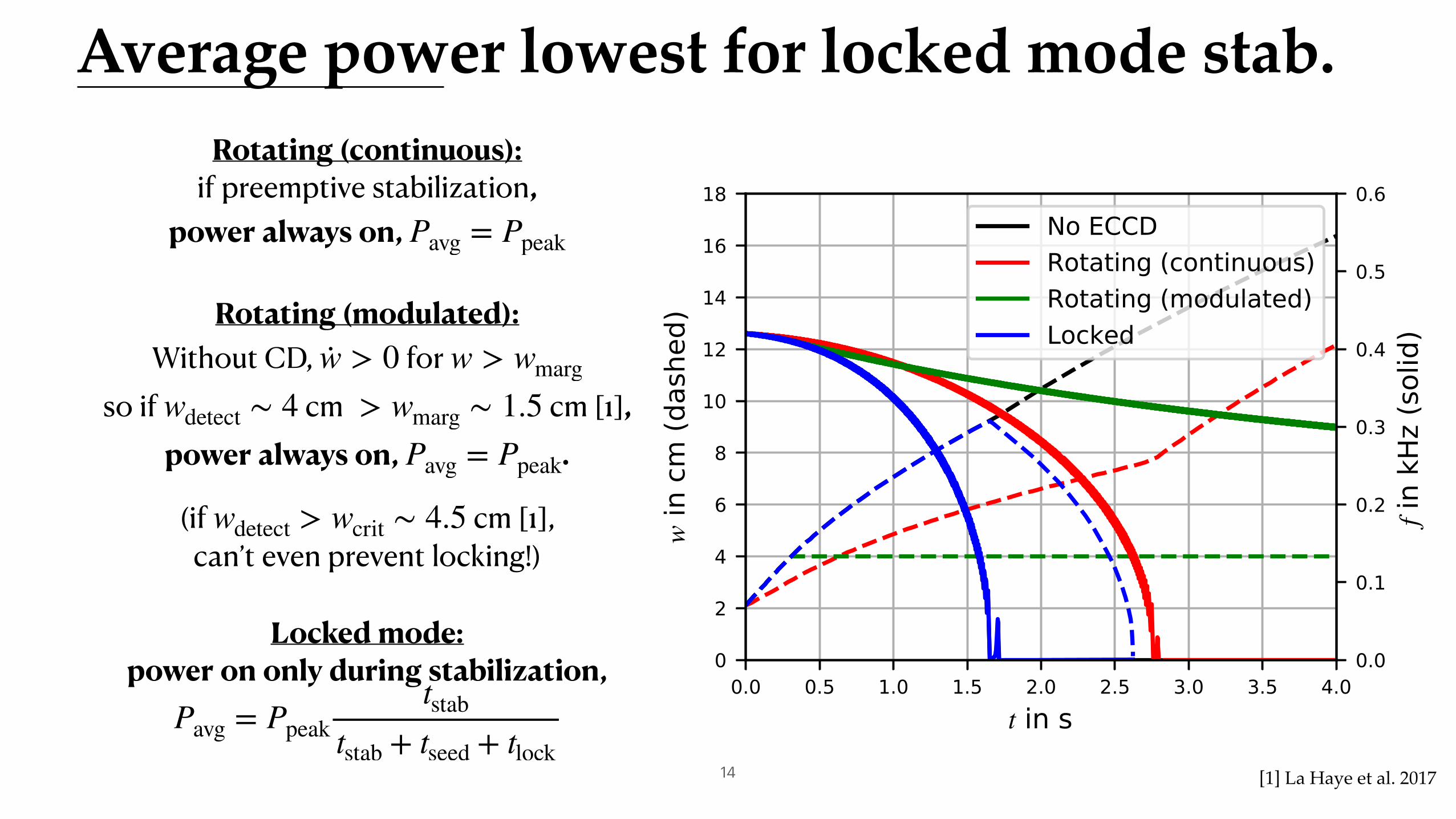
Average power lowest for locked mode stab.
14
Rotating (continuous): if preemptive stabilization,
power always on, Pavg = Ppeak
Rotating (modulated): Without CD, for
so if cm cm [1], power always on, .
(if cm [1], can’t even prevent locking!)
·w > 0 w > wmarg
wdetect ∼ 4 > wmarg ∼ 1.5Pavg = Ppeak
wdetect > wcrit ∼ 4.5
Locked mode: power on only during stabilization,
Pavg = Ppeaktstab
tstab + tseed + tlock[1] La Haye et al. 2017

15
The case for Locked Mode stabilization
Can stabilize small LM with low peak and average EC power,…… more robust to broadening, misalignment and large seeding.
No need to stabilize rotating mode, let island lock.⇒
Hard to avoid LMs in large tokamaks like ITER…… but small LMs are tolerable …
Prepare LM Stabilization strategy, at least as back-up.
Can even consider stabilization of large LMs to further reduce disruptivity: see A. Reiman talk Friday 11:10
⇒
Large potential impact on ITER fusion gain and disruptivity, need to pay more attention to Locked Modes.
https://arxiv.org/abs/2106.06581

Thank you!Questions and feedback are welcome
https://arxiv.org/abs/2106.06581

[1] La Haye, R. J., Paz-Soldan, C. & Liu, Y. Q. Effect of thick blanket modules on neoclassical tearing mode locking in ITER. Nucl. Fusion 57, 014004 (2017).
[2] Polevoi, La Haye, private comm. (2019)
[2 ] Brookman, M. W. et al. Resolving ECRH Deposition Broadening Due to Edge Turbulence in DIII-D. Physics of Plasmas 28, (2021)
[3] Snicker, A. et al. The effect of density fluctuations on electron cyclotron beam broadening and implications for ITER. Nucl. Fusion 58, 016002 (2018).
[4] Vries, P. C. et al. The Influence of an ITER-like Wall on Disruptions at JET. Physics of Plasmas 21 (2014).
[5] Volpe, F. A. et al. Avoiding Tokamak Disruptions by Applying Static Magnetic Fields That Align Locked Modes with Stabilizing Wave-Driven Currents. Physical Review Letters 115, (2015).
[6] Nelson, A.O. et al. Experimental evidence of ECCD-based NTM suppression threshold reduction during mode locking on DIII-D. Plasma Phys. Control. Fusion in press, (2020)
[7] F. Volpe, presentation at Madison MHD control workshop (2017), https://pl.apam.columbia.edu/files/seaspllab/presentations/2017_MHDWS_volpe_LMReview.pdf
[8] Evans, T. E. et al. Suppression of Large Edge-Localized Modes in High-Confinement DIII-D Plasmas with a Stochastic Magnetic Boundary. Physical Review Letters 92, (2004).
[9] Nave, M. F. F. & Wesson, J. A. Mode locking in tokamaks. Nucl. Fusion 30, 2575–2583 (1990).
[10] Fitzpatrick, R. Interaction of tearing modes with external structures in cylindrical geometry (plasma). Nucl. Fusion 33, 1049–1084 (1993).
[11] De Lazzari, D. & Westerhof, E. On the merits of heating and current drive for tearing mode stabilization. Nuclear Fusion 49, 075002 (2009).
[12] van den Brand, H., de Baar, M. R., Cardozo, N. J. L. & Westerhof, E. Integrated modelling of island growth, stabilization and mode locking: consequences for NTM control on ITER. Plasma Phys. Control. Fusion 54, 094003 (2012).
[13] Haye, R. J. L. et al. Cross–machine benchmarking for ITER of neoclassical tearing mode stabilization by electron cyclotron current drive. Nucl. Fusion 46, 451–461 (2006).
[14] Bertelli, N. et al. Requirements on Localized Current Drive for the Suppression of Neoclassical Tearing Modes. Nuclear Fusion 51 (2011).
[15] Yu, Q. & Günter, S. Locking of neoclassical tearing modes by error fields and its stabilization by RF current. Nucl. Fusion 48, 065004 (2008).
[16] Hender, T. C. et al. Chapter 3: MHD stability, operational limits and disruptions. Nucl. Fusion 47, S128–S202 (2007).
[17] Glasser, A. H., Greene, J. M. & Johnson, J. L. Resistive instabilities in general toroidal plasma configurations. The Physics of Fluids 18, 875–888 (1975).
[18] Fitzpatrick, R. Helical temperature perturbations associated with tearing modes in tokamak plasmas. Physics of Plasmas 2, 825–838 (1995).
3/4
17
References
Appendix 1:Glossary of quantities and values

Resistive time:
Radius of surface:
Resistivity:
Electron temperature:
Trapped particle fraction:
Effective ion charge [2]:
Shear length:
Bootstrap current:
Average parallel current:
Radius of resistive wall:
Resistive wall time:
Alfven time:
Original rotation frequency:
Original momentum confinement time:
Fitting coefficients:
τR = μ0r2s η−1
q = 2 rs = 155 cmη−1 = 1258(Te/1 eV)3/2 fϵ/Zeff
Te = 5.63 keVfϵ = 0.26
Zeff = 1.53Lq = 94 cm
jBS = 7.2 ⋅ 104 A/m2
j∥ = 38.8 ⋅ 104 A/m2
rw = 1.25 aτw = 14 ms
τA0 = 3 μs
ω0 = 2π ⋅ 0.42 kHz
τM0 = 3.7 sC1 = 1/80, CM = 12
19
Values used in simulations (mostly from [1])
[1] La Haye et al 2017[2] Polevoi & La Haye 2019

Appendix 2:Rutherford equation
term by term

Classical tearing index Δ′ 0
The classical tearing mode contribution is given by the jump in the derivative of the magnetic perturbation at the rational surface :
.
For a fast rotating island, the resistive wall acts like a perfect conductor, thus giving an additional stabilizing contribution which can be approximated as [9]
,
where is the wall radius, the resistive wall time and the island rotation frequency.
ψ rs
rsΔ′ 0 =∂ψ∂r (r+
s ) − ∂ψ∂r (r−
s )
ψ(rs)
rsΔ′ wall = − 2m ( r+s
rw )2m (ωτw)2[1 − ( r+
s
rw )2m
]1 + (ωτw)2[1 − ( r+
s
rw )2m]
2
rw τw ω
[9] Nave & Wesson 1990

Error field or RMP Δ′ EF,RMP
The error field or RMP term is given by [10]
,
The vacuum island width is obtained from the magnetic field perturbation at the edge [10], which can be related to the radial error field at the plasma edge [16], such that
To avoid error field penetration, ITER has a 3-field requirement
.
It thus makes sense to take .
rsΔ′ EF,RMP = 2m ( wvac
w )2
cos(ϕ − ϕEF)
brn = Br /Bt = mψ(a)a
wvac = 4a brnBt
mBp
Lq
a ( rs
a )m
=brn
10−5⋅ 2.2 cm
B3−mode = B22,1 + 0.8B2
3,1 + 0.2B2r1,1 ≤ 5 ⋅ 10−5Bt
wvac ∼ 2.5 − 5.0 cm[10] Fitzpatrick 1993[16] Hender et al. 2007
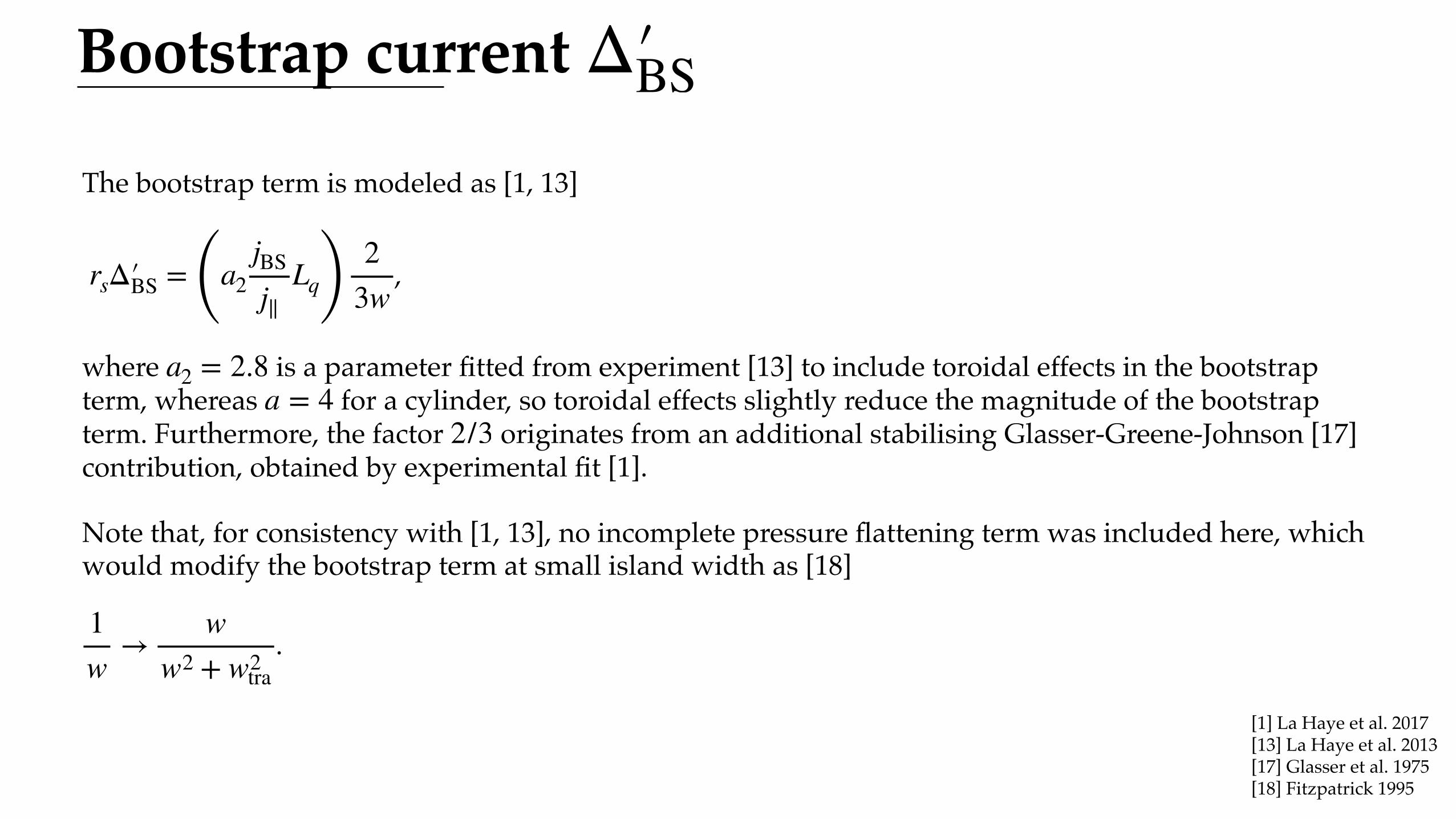
Bootstrap current Δ′ BS
The bootstrap term is modeled as [1, 13]
,
where is a parameter fitted from experiment [13] to include toroidal effects in the bootstrap term, whereas for a cylinder, so toroidal effects slightly reduce the magnitude of the bootstrap term. Furthermore, the factor originates from an additional stabilising Glasser-Greene-Johnson [17] contribution, obtained by experimental fit [1].
Note that, for consistency with [1, 13], no incomplete pressure flattening term was included here, which would modify the bootstrap term at small island width as [18]
.
rsΔ′ BS = (a2jBS
j∥Lq) 2
3w
a2 = 2.8a = 4
2/3
1w
→w
w2 + w2tra
[1] La Haye et al. 2017[13] La Haye et al. 2013[17] Glasser et al. 1975[18] Fitzpatrick 1995

Polarization current Δ′ pol
The polarization current is modeled as [1]
,
with the ion banana width .
The term stabilizes the island at small widths. The combination of bootstrap and polarisation current terms is negative (stabilizing) for and maximal for .
rsΔ′ pol = − (a2jBS
j∥Lq) 3w2
ib
w3
wib ∼ ϵ1/2ρθ,i ≈ 0.7 cm
w < 3wib/ 2 ∼ 2.1wib w = 3/2 ⋅ 3wib ∼ 3.7wib
[1] La Haye et al. 2017

Current drive Δ′ CDThe current drive term is modeled as [11]
,
where is the width of the gaussian deposition and . The peak driven current , with the quantity a measure of the current drive efficiency. The quantity is approximately constant for a given toroidal
launching angle. We thus take to match the value in [14] and appropriately decrease the peak current density when including broadening effects. Broadening leaves unchanged, but reduces , so must also be reduced accordingly.
The stabilization efficiency is given by [11]
,
where is a flux coordinate ( at the island O-point and at the separatrix), a helical angle and angular brackets indicate flux surface averages. The power deposition is assumed to be a gaussian in the radial direction and a delta function in the helical angle,
.
The stabilization efficiency is evaluated instantaneously as the phase evolves, even for the rotating island. Note in particular that no fast rotation needs to be assumed for the rotating island case, and that no arithmetic approximations to the stabilization efficiency are used.
rsΔ′ CD = − (a2jBS
j∥Lq) 3π3/2
4wdep
w2dep
w2ηNTMηaux
wdep 1/e ηNTM = jCD,max/jBS jCD,max = PtotγCDγCD = jCD,max/Ptot ∝ (ICD/wdep)/Ptot ICD/Ptot
γCDPtot jCD,max γCD
ηaux =∫ ∞
−1dΩ ⟨pEC⟩ ⟨cos(mξ)⟩
⟨1⟩
∫ ∞−1
dΩ ⟨pEC⟩
Ω = 8x2/w2 − cos(mξ) Ω = − 1 Ω = 1 ξ = θ − n /mϕ
pEC ∝ exp (−4(x − xdep)2/w2dep) δ(mξ − ϕ + ϕEC)
[11] De Lazzari & Westerhof 2009[14] Bertelli et al. 2011
From [14]

Appendix 3:Equation of angular motion
term by term
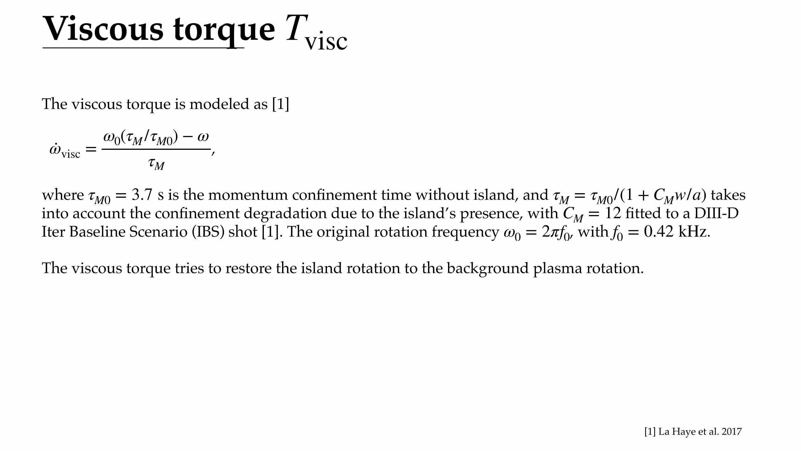
Viscous torque Tvisc
The viscous torque is modeled as [1]
,
where is the momentum confinement time without island, and takes into account the confinement degradation due to the island’s presence, with fitted to a DIII-D Iter Baseline Scenario (IBS) shot [1]. The original rotation frequency , with .
The viscous torque tries to restore the island rotation to the background plasma rotation.
·ωvisc =ω0(τM /τM0) − ω
τM
τM0 = 3.7 s τM = τM0/(1 + CMw/a)CM = 12
ω0 = 2πf0 f0 = 0.42 kHz
[1] La Haye et al. 2017
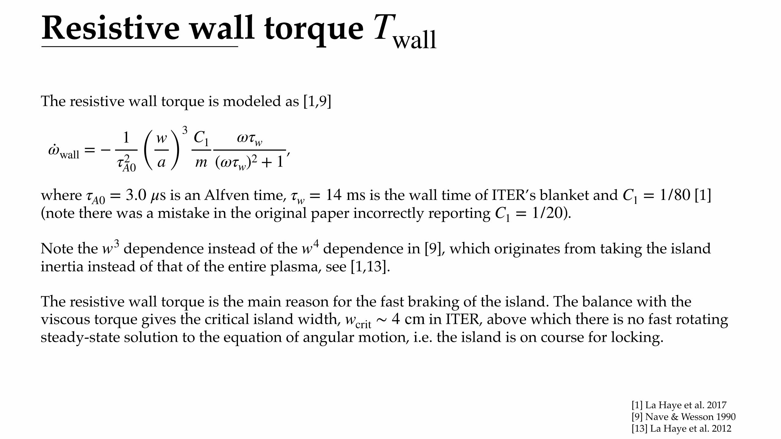
Resistive wall torque Twall
The resistive wall torque is modeled as [1,9]
,
where is an Alfven time, is the wall time of ITER’s blanket and [1] (note there was a mistake in the original paper incorrectly reporting ).
Note the dependence instead of the dependence in [9], which originates from taking the island inertia instead of that of the entire plasma, see [1,13].
The resistive wall torque is the main reason for the fast braking of the island. The balance with the viscous torque gives the critical island width, in ITER, above which there is no fast rotating steady-state solution to the equation of angular motion, i.e. the island is on course for locking.
·ωwall = −1
τ2A0 ( w
a )3 C1
mωτw
(ωτw)2 + 1
τA0 = 3.0 μs τw = 14 ms C1 = 1/80C1 = 1/20
w3 w4
wcrit ∼ 4 cm
[1] La Haye et al. 2017[9] Nave & Wesson 1990[13] La Haye et al. 2012
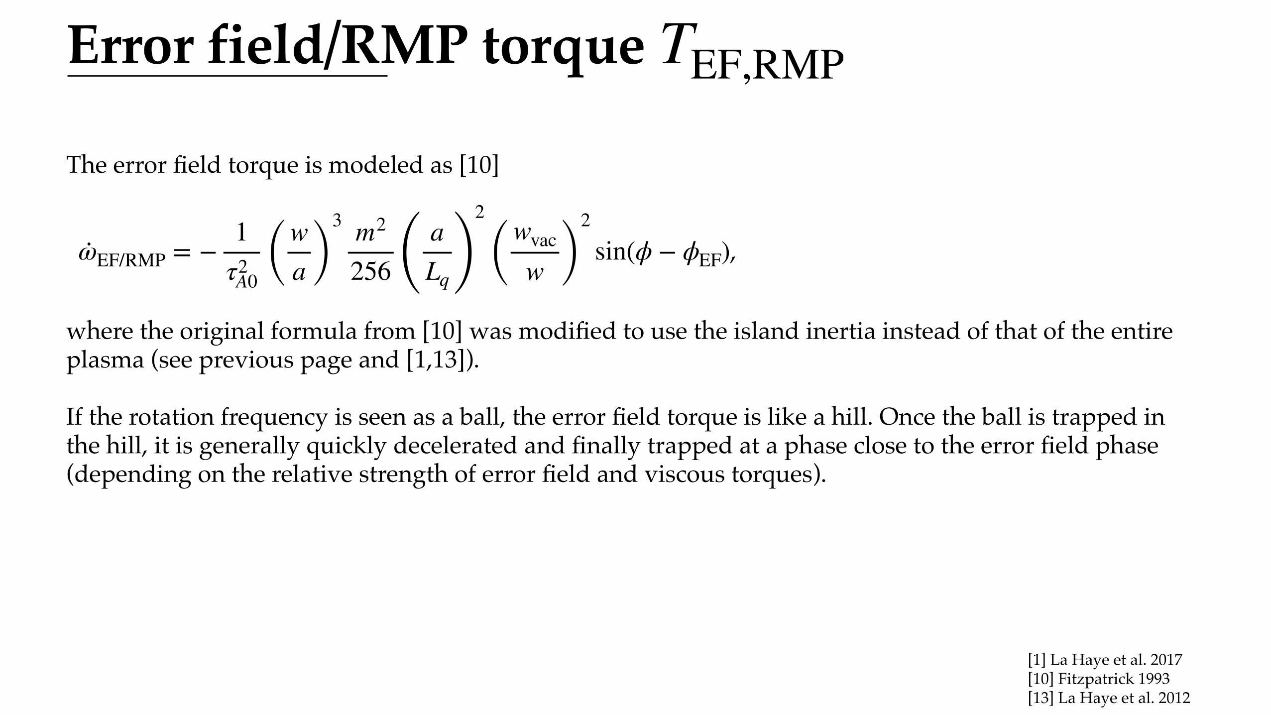
Error field/RMP torque TEF,RMP
The error field torque is modeled as [10]
,
where the original formula from [10] was modified to use the island inertia instead of that of the entire plasma (see previous page and [1,13]).
If the rotation frequency is seen as a ball, the error field torque is like a hill. Once the ball is trapped in the hill, it is generally quickly decelerated and finally trapped at a phase close to the error field phase (depending on the relative strength of error field and viscous torques).
·ωEF/RMP = −1
τ2A0 ( w
a )3 m2
256 ( aLq )
2
( wvac
w )2
sin(ϕ − ϕEF)
[1] La Haye et al. 2017[10] Fitzpatrick 1993[13] La Haye et al. 2012
30
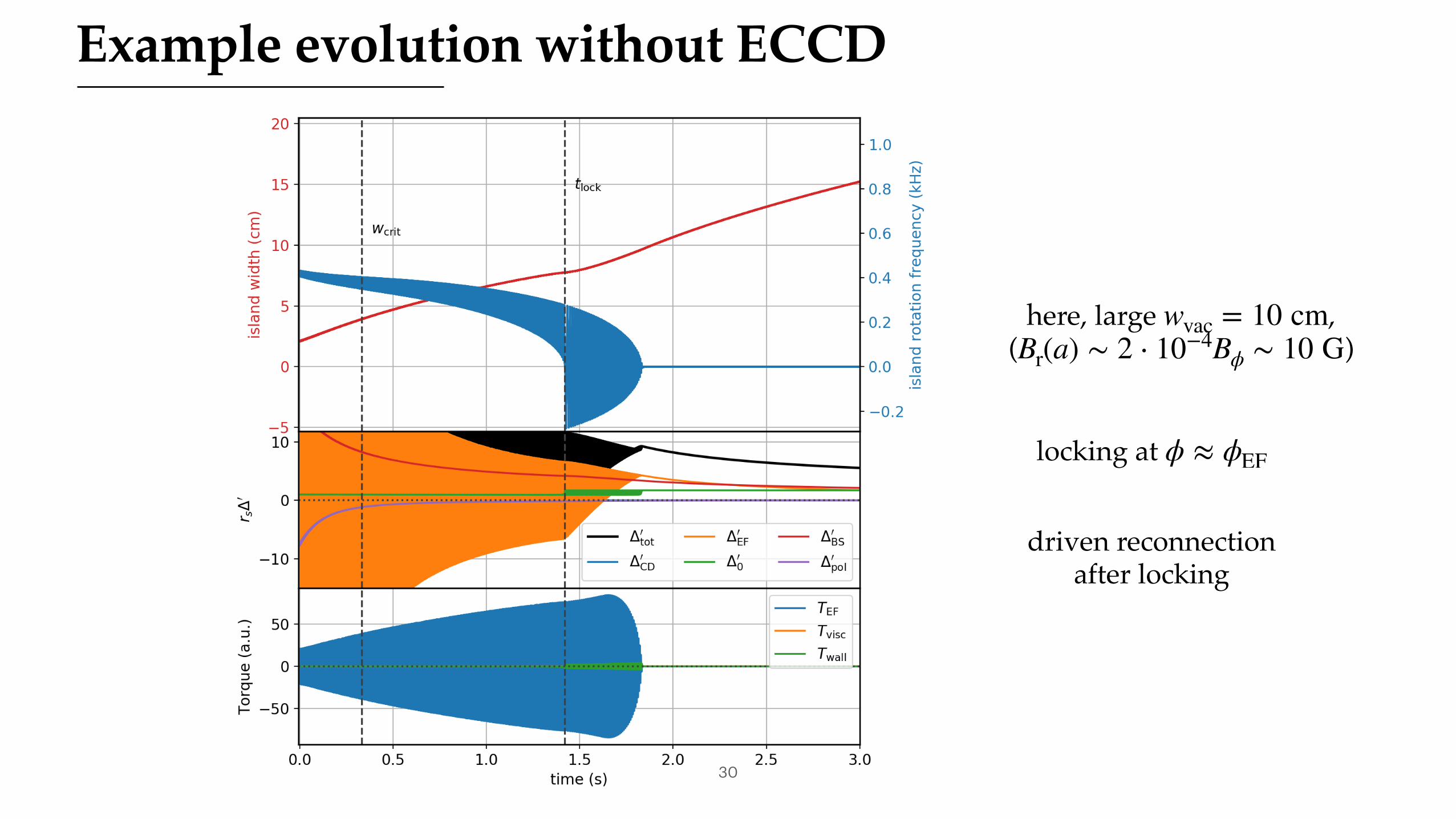
Example evolution without ECCD
here, large ,( )
wvac = 10 cmBr(a) ∼ 2 ⋅ 10−4Bϕ ∼ 10 G
locking at ϕ ≈ ϕEF
driven reconnectionafter locking
Appendix 4:Optimal toroidal launching angle,
different scenarios,detection threshold,
error field, …
(Older plots that used slightly different parameters, Results should still hold qualitatively)

Optimal toroidal launching angle
32
Base settings:Broadening factor of 3
cm
cm
wseed = 2.1wvac = 2.5 cmwdetect = 4
Design toroidal launching angle remains optimal for locked mode stabilization
β = 20∘
taken from [14]ηCD(β)
[14] Bertelli et al. 2011
33
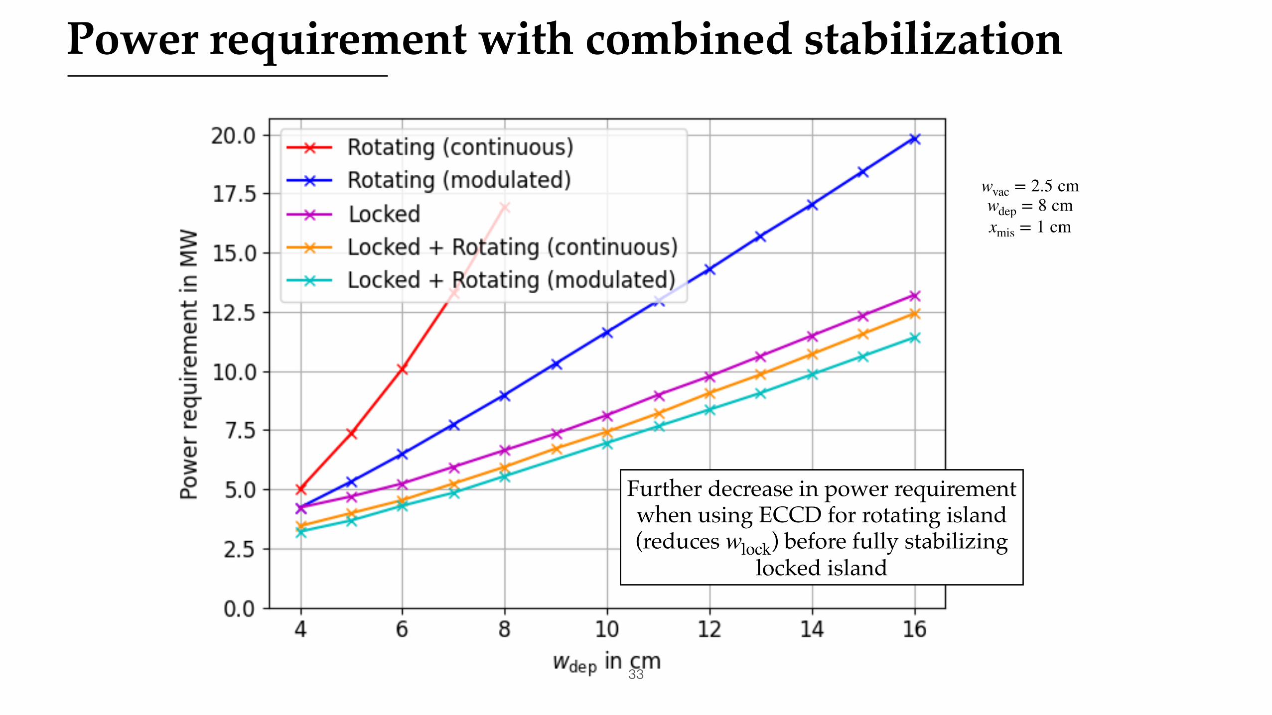
Power requirement with combined stabilization
wvac = 2.5 cmwdep = 8 cmxmis = 1 cm
Further decrease in power requirement when using ECCD for rotating island(reduces ) before fully stabilizing
locked islandwlock
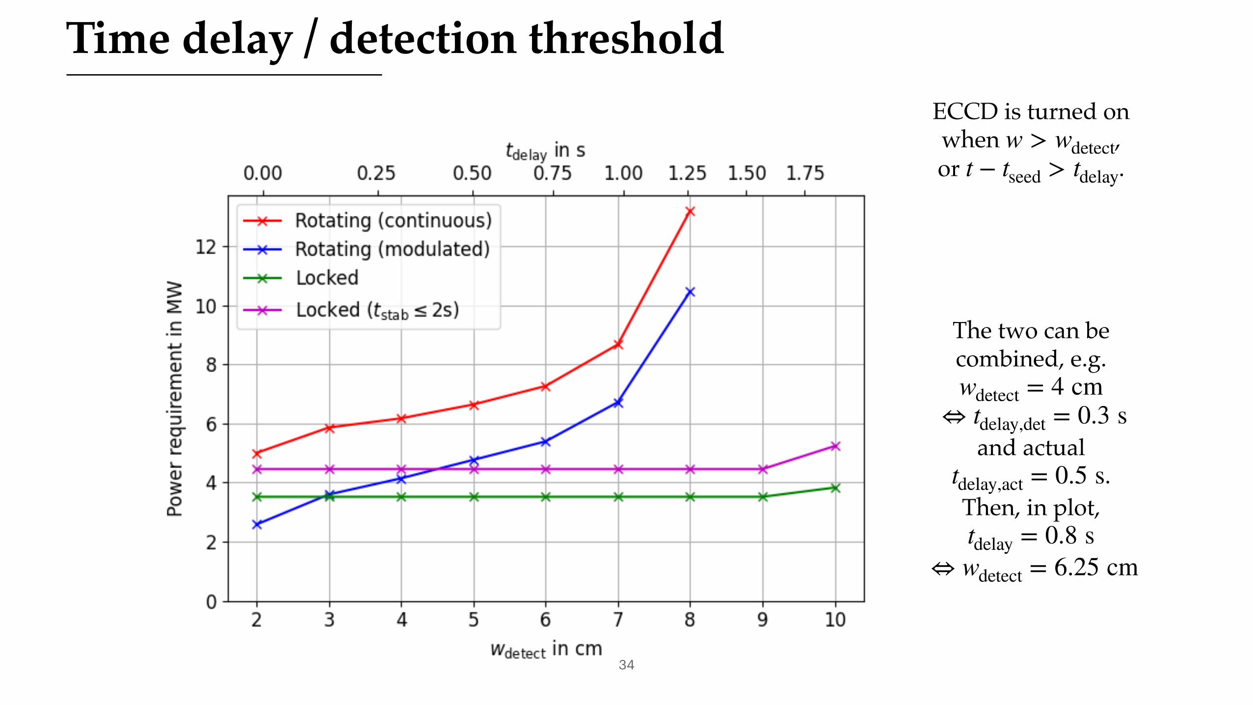
34
Time delay / detection thresholdECCD is turned onwhen ,or .
w > wdetectt − tseed > tdelay
The two can becombined, e.g.
and actual.
Then, in plot,
wdetect = 4 cm⇔ tdelay,det = 0.3 s
tdelay,act = 0.5 s
tdelay = 0.8 s⇔ wdetect = 6.25 cm
35
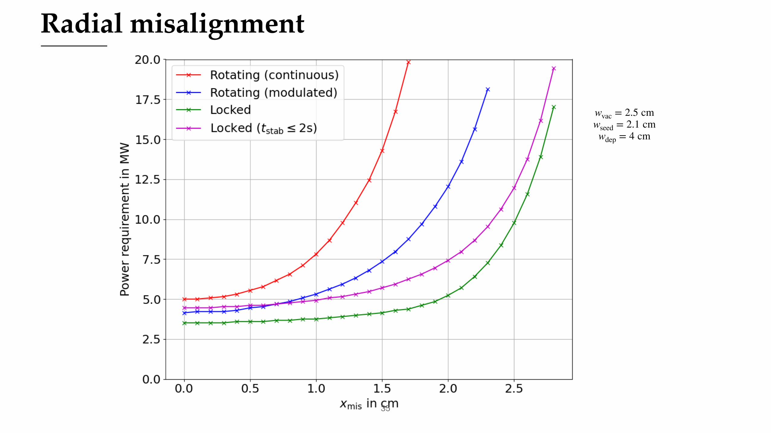
Radial misalignment
wvac = 2.5 cmwseed = 2.1 cmwdep = 4 cm
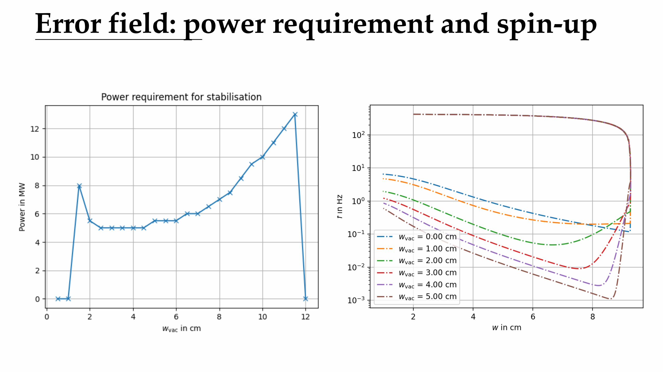
Error field: power requirement and spin-up
Appendix 5:Geometry of NTM stabilization
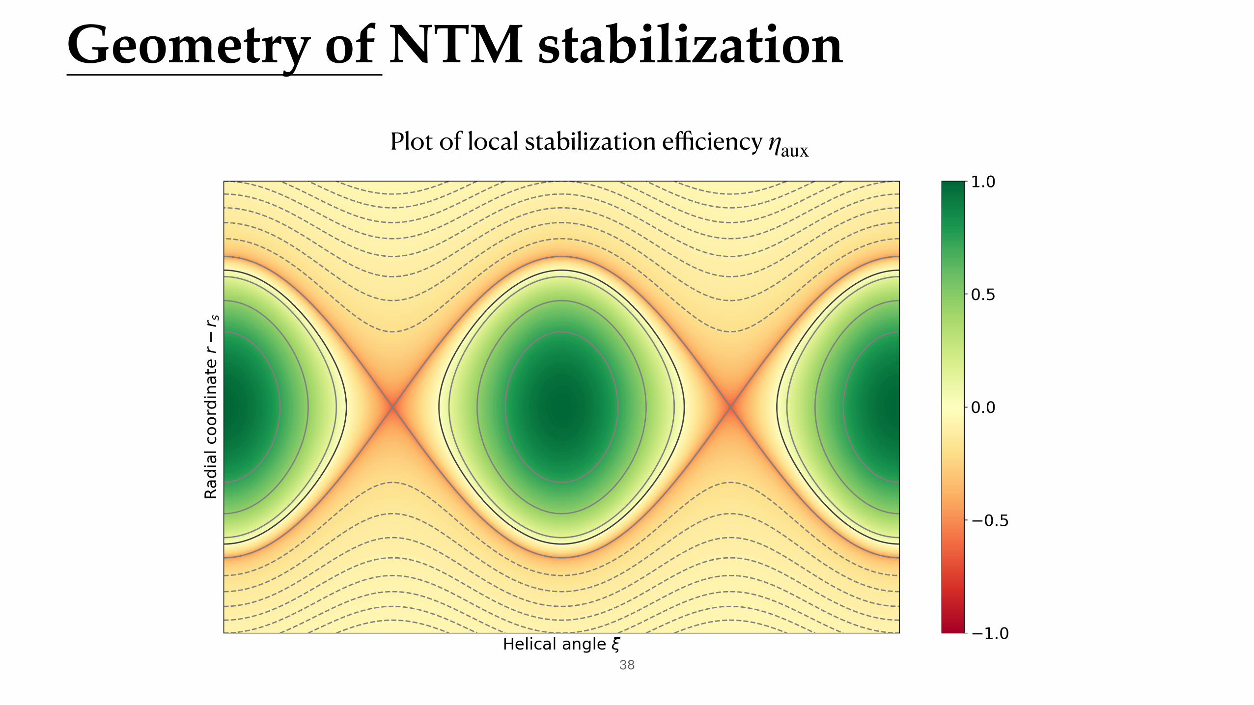
Geometry of NTM stabilization
38
Plot of local stabilization efficiency ηaux

Rotating island, continuous ECCD
39
Average efficiency: ⟨ηaux⟩ = 0.32
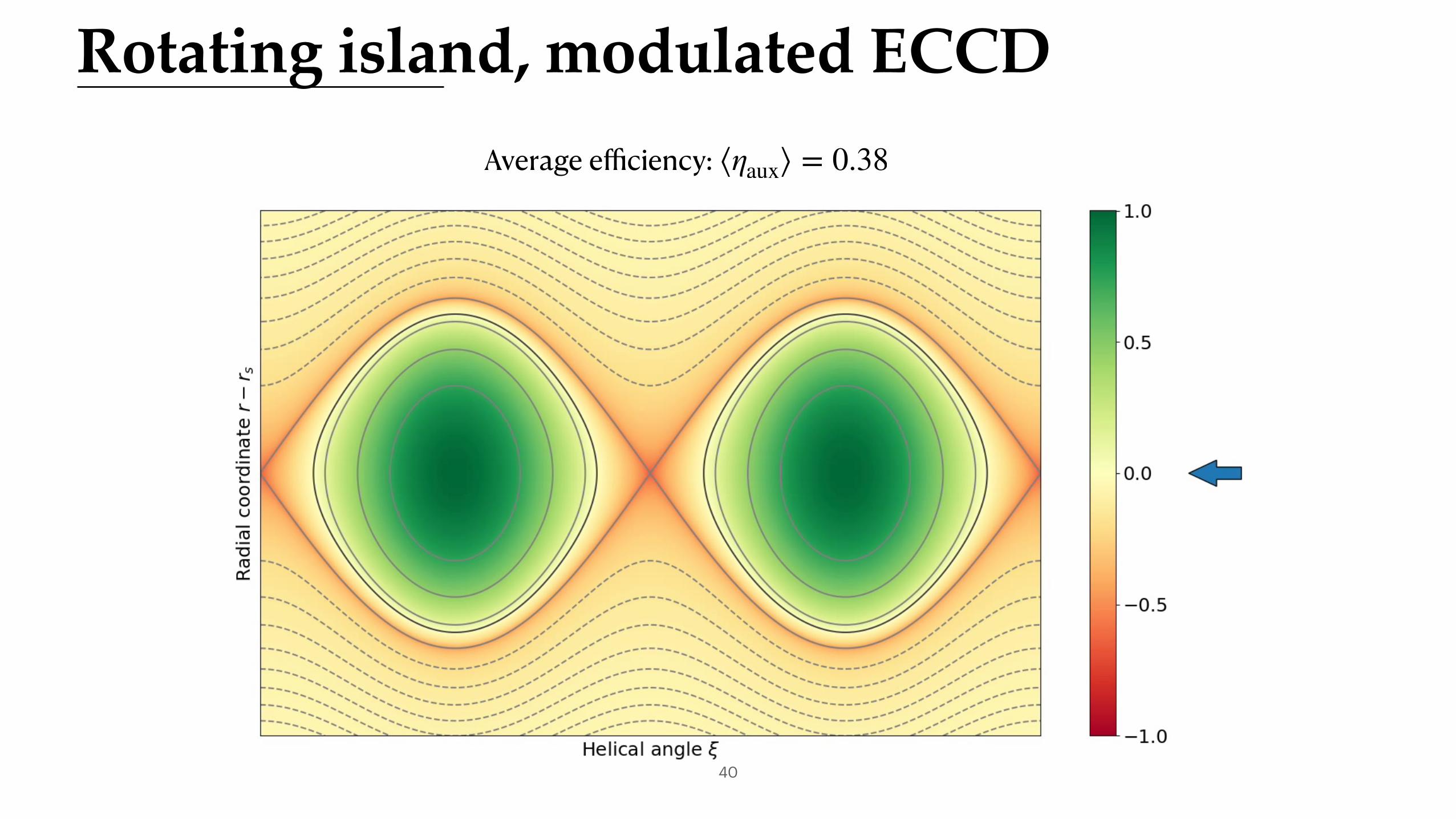
Rotating island, modulated ECCD
40
Average efficiency: ⟨ηaux⟩ = 0.38

Locked island
41
Higher efficiency. + larger radial width at O-point reduces
sensitivity to misalignment and broadeningEfficiency: ηaux = 0.95