TS C203read.pudn.com/downloads147/doc/comm/636366/3G 标准/RRC... · Web viewFor IP domain...
190
CWTS China Wireless Telecommunication Standard; Working Group 1 (WG1); TD-SCDMA RRC Protocol Specification TS C203 V2.1.0 (1999-10) Technical Specification
Transcript of TS C203read.pudn.com/downloads147/doc/comm/636366/3G 标准/RRC... · Web viewFor IP domain...

CWTS
China Wireless Telecommunication Standard;Working Group 1 (WG1);
TD-SCDMARRC Protocol Specification
TS C203 V2.1.0 (1999-10)Technical Specification

Contents1. SCOPE............................................................................................................................................................... 4
2. REFERENCES.................................................................................................................................................. 4
3. DEFINITIONS, SYMBOLS AND ABBREVIATIONS....................................................................................4
3.1 Definitions............................................................................................................................................... 43.2 Abbreviations........................................................................................................................................... 4
4. GENERAL......................................................................................................................................................... 7
5 RRC SERVICES PROVIDED TO UPPER LAYERS.....................................................................................9
6 SERVICES EXPECTED FROM LOWER LAYERS......................................................................................9
6.1 Services expected from Layer 2................................................................................................................ 96.2 Services expected from Layer 1............................................................................................................. 10
7 FUNCTIONS OF RRC.................................................................................................................................... 10
8 ELEMENTARY RRC PROCEDURES......................................................................................................... 11
8.1 Idle mode procedures............................................................................................................................. 128.1.1 Paging........................................................................................................................................ 128.1.2 Notification................................................................................................................................ 12
8.2 RRC connection establishment and release procedures...........................................................................138.2.1 RRC Connection Establishment procedure..................................................................................138.2.2 RRC Connection Release............................................................................................................ 168.2.3 RRC Connection re-establishment...............................................................................................16
8.3 RRC connected mode procedures........................................................................................................... 178.3.1 Radio Bearer Related Procedures...............................................................................................178.3.2 Transport Channel Reconfiguration............................................................................................198.3.3 Transport Format Combination Control......................................................................................208.3.4 Physical Channel Reconfiguration..............................................................................................208.3.5 Mobility Related Procedures.......................................................................................................218.3.6 RRC Connected mode procedures which use Paging...................................................................288.3.7 Procedures related to measurement and monitoring....................................................................298.3.8 Other procedures in connected mode..........................................................................................32
8.4 Procedures which apply to both idle and RRC Connected mode......................................................................368.4.1 Broadcast of system information.................................................................................................36
9 DEFAULT ACTIONS ON RECEPIT OF AN IE...........................................................................................37
9.1 CN information elements....................................................................................................................... 379.2 RAN mobility information elements.......................................................................................................379.3 UE information elements........................................................................................................................ 38
9.3.1 Activation time............................................................................................................................ 389.4 Radio bearer information elements......................................................................................................... 389.5 Transport channel information elements.................................................................................................38
9.5.1 Transport Format Set.................................................................................................................. 389.5.2 Transport format combination set................................................................................................389.5.3 Transport format combination subset..........................................................................................38
9.6 Physical channel information elements...................................................................................................389.6.1 Frequency info............................................................................................................................ 389.6.2 PRACH info................................................................................................................................ 389.6.3 Uplink DPCH info...................................................................................................................... 399.6.4 Downlink DPCH info.................................................................................................................. 39
9.7 Measurement information elements........................................................................................................ 399.8 Other information elements.................................................................................................................... 39
2 RRC Protocol Specification

10 MESSAGE AND INFORMATION ELEMENT FUNCTIONAL DEFINITION AND CONTENT..........39
10.1 Radio Resource Control messages................................................................................................................. 4010.1.1 RRC Connection Mobility Messages........................................................................................................ 4010.1.2 Measurement Messages........................................................................................................................... 4810.1.3 Paging and Notification Messages.......................................................................................................... 5210.1.4 RRC Connection Establishment and maintenance messages....................................................................5310.1.5 Radio Bearer control messages............................................................................................................... 6010.1.6 System Information Messages.................................................................................................................. 74
10.1.7 Other Messages........................................................................................................................................... 7710.2 Information element functional definitions....................................................................................................80
10.2.1 CN Information elements......................................................................................................................... 8010.2.2 RAN mobility Information elements......................................................................................................... 8010.2.3 UE Information elements......................................................................................................................... 8110.2.4 Radio Bearer Information elements......................................................................................................... 8810.2.5 Transport CH Information elements........................................................................................................ 9110.2.6 Physical CH Information elements.......................................................................................................... 9410.2.7 Measurement Information elements.......................................................................................................10210.2.8 Other Information elements................................................................................................................... 114
11 MESSAGE AND INFORMATION ELEMENT ABSTRACT SYNTAX (WITH ASN.1)..............................115
12 MESSAGE TRANSFER SYNTAX.................................................................................................................. 116
13 PROTOCOL STATES..................................................................................................................................... 116
13.1 RRC States and State Transitions including GSM.............................................................................11613.2 Transition from Idle Mode to RAN Connected Mode........................................................................11713.3 RAN Connected Mode States and Transitions...................................................................................117
13.3.1 CELL_DCH state...................................................................................................................... 11713.3.2 CELL_FACH state.................................................................................................................... 11913.3.3 CELL_PCH state...................................................................................................................... 12213.3.4 RRA_PCH State....................................................................................................................... 123
13.4 Inter-system handover with PSTN/ISDN domain services.................................................................12413.5 Inter-system handover with IP domain services.................................................................................12413.6 Inter-system handover with simultaneous IP and PSTN/ISDN domain services.................................125
13.6.1 Inter-system handover RAN to GSM / BSS.................................................................................12513.6.2 Inter-system handover GSM / BSS to RAN.................................................................................125
14 PROTOCOL TIMERS, COUNTERS AND OTHER PARAMETERS..........................................................125
14.1 Timer for RACH/FACH or PCH substate.....................................................................................................12614.1.1 Description........................................................................................................................................... 12614.1.2 TIMERS for UE..................................................................................................................................... 126
14.2 Timers for RRC Connection Setup Procedure..............................................................................................12614.2.1 Description........................................................................................................................................... 12614.2.2 TIMERS for UE..................................................................................................................................... 12714.2.3 COUNTER for UE................................................................................................................................. 12714.2 .4TIMER for RAN (REFERENCE)........................................................................................................... 12714.3.1Description............................................................................................................................................ 12714.3.2 TIMERS for UE..................................................................................................................................... 12814.3.3 TIMERS for RAN (REFERENCE)......................................................................................................... 12814.4.1Description............................................................................................................................................ 12814.4.2 TIMERS for UE..................................................................................................................................... 12914.3 COUNTER for UE................................................................................................................................... 12914.4 TIMER for RAN (REFERENCE).............................................................................................................. 129
14.1 TIMERS for UE........................................................................................................................................... 13014.2 COUNTERS for UE..................................................................................................................................... 131
15 SPECIFIC FUNCTIONS (IF APPLICABLE).................................................................................................131
15.1 Intra-frequency measurements..................................................................................................................... 13115.1.1 Intra-frequency measurement quantities................................................................................................13115.1.2 Intra-frequency reporting events........................................................................................................... 13215.1.3 Event-triggered periodic intra-frequency measurement reports............................................................136
3 RRC Protocol Specification
15.1.4 Mechanisms available for modifying intra-frequency measurement reporting behaviour......................13815.1.5 Report quantities................................................................................................................................... 140
15.2 Traffic Volume Measurements..................................................................................................................... 14115.2.1 Traffic Volume Measurement Quantity..................................................................................................14115.2.2 Traffic Volume reporting events............................................................................................................ 14115.2.3 Traffic volume reporting mechanisms....................................................................................................141
15.3 UE internal measurements................................................................................................................ 14215.3.1 UE internal measurement quantities..........................................................................................14215.3.2 UE internal measurement reporting events................................................................................142
15.4 Dynamic Resource Allocation Control of Uplink DCH.....................................................................144
16 PRIMITIVES BETWEEN RRC AND UPPER LAYERS.........................................................................145
17 HANDLING OF UNKNOWN, UNFORESEEN AND ERRONEOUS PROTOCOL DATA.........................145
18 SDL................................................................................................................................................................... 145
19HISTORY.......................................................................................................................................................... 146
1. ScopeThe scope of this specification is to describe the Radio Resource Control protocol for the TD-SCDMA radio system.
2. References[1] UMTS 25.XX, 'Vocabulary for the RAN'
[2] CWTS TS C001(V2.0.0), 'Radio Interface Protocol Architecture'
[3] CWTS TS C003(V2.0.0) 'Description of UE states and procedures in connected mode'
3. Definitions, Symbols and abbreviations
3.1 DefinitionsSee [1] for definition of fundamental concepts and vocabulary
3.2 AbbreviationsACK Acknowledgement
AM Acknowledged Mode
AS Access Stratum
BCCH Broadcast Control Channel
BCFE Broadcast Control Functional Entity
BER Bite Error Rate
4 RRC Protocol Specification

BLER BLock Error Rate
BSS Base Station Sub-system
C Conditional
CCPCH Common Control Physical CHannel
CCCH Common Control Channel
CN Core Network
CM Connection Management
C-RNTI CRNC RNTI
DCA Dynamic Channel Allocation
DCCH Dedicated Control Channel
DCFE Dedicated Control Functional Entity
DCH Dedicated Channel
DC-SAP Dedicated Control SAP
DL Downlink
DRAC Dynamic Resource Allocation Control
DTCH Dedicated Traffic Channel
FACH Forward Access Channel
FDD Frequency Division Duplex
FFS For Further Study
ID Identifier
IMEI International Mobile Equipment Identity
IMSI International Mobile Subscriber Identity
IP Internet Protocol
ISCP Interference on Signal Code Power
LAI Location Area Identity
L1 Layer 1
L2 Layer 2
L3 Layer 3
M Mandatory
MAC Media Access Control
MCC Mobile Country Code
MM Mobility Management
MNC Mobile Network Code
MS Mobile Station
NAS Non Access Stratum
5 RRC Protocol Specification
Nt-SAP Notification SAP
NW Network
O Optional
ODMA Opportunity Driven Multiple Access
PCCH Paging Control Channel
PCH Paging Channel
PDU Protocol Data Unit
PDSCH Physical Downlink Shared Channel
PLMN Public Land Mobile Network
PNFE Paging and Notification Control Functional Entity
PRACH Physical Random Access CHannel
P-TMSI Packet Temporary Mobile Subscriber Identity
PUSCH Physical Uplink Shared Channel
QoS Quality of Service
RAB Radio access bearer
RAI Routing Area Identity
RACH Random Access CHannel
RB Radio Bearer
RFE Routing Functional Entity
RL Radio Link
RLC Radio Link Control
RNTI Radio Network Temporary Identifier
RFE Routing Functional Entity
RNC Radio Network Controller
RRC Radio Resource Control
RSCP Received Signal Code Power
RSSI Received Signal Strength Indicator
SAP Service Access Point
SCFE Shared Control Function Entity
SF Spreading Factor
SIR Signal to Interference Ratio
SSDT Site Selection Diversity Transmission
S-RNTI SRNC - RNTI
tbd to be decided
TDD Time Division Duplex
6 RRC Protocol Specification

TF Transport Format
TFCS Transport Format Combination Set
TFS Transport Format Set
TME Transfer Mode Entity
TMSI Temporary Mobile Subscriber Identity
Tr Transparent
Tx Transmission
UE User Equipment
UL Uplink
UM Unacknowledged Mode
UMTS Universal Mobile Telecommunications System
UNACK Unacknowledgement
RRA UTRAN Registration Area
UTRAN UMTS Terrestrial Radio Access Network
4. General The functional entities of the RRC layer are described below:
Routing of higher layer messages to different MM/CM entities (UE side) or different core network domains (RAN side) is handled by the Routing Function Entity (RFE)
Note:during CWTS WG #4 meeting, if the RFE should be included in RRC or not has been discussed and decided to left it ffs.
Broadcast functions are handled in the broadcast control function entity (BCFE). BCFE offers RRC services by the GC-SAP and uses the lower layer services provided by Tr-SAP.
Paging of idle mode UE(s) is controlled by the paging and notification control function entity (PNFE). PNFE offers RRC services by the Nt-SAP and uses the lower layer services provided by Tr-SAP.
The Dedicated Control Function Entity (DCFE) handles all functions specific to one UE. The DCFE offers RRC services by the DC-SAP and can use lower layer services of UM/AM-SAP and Tr-SAP depending on the message to be sent and on the current UE service state.
The Shared Control Function Entity (SCFE) location in the C-RNC is used in conjunction with DCFE to control the allocation of the PDSCH and PUSCH using lower layers services of UM-SAP and Tr-SAP.
The Transfer Mode Entity (TME) handles the mapping between the different entities inside the RRC layer and the SAP's provided by RLC.
Logical information exchange is necessary also between the RRC sublayer functional entities. Most of that is implementation dependent and not necessary to present in detail in a specification
Figure 1 shows the RRC model for the UE side and Figure 2 shows the RRC model for the UTRAN side.
[Editors note: Some further clarification in the diagrams may be beneficial to acknowledge the fact that a DC-SAP for example might be offered over a dedicated channel (with RRC connection terminated in SRNC) whereas GC-
7 RRC Protocol Specification

SAP and Nt-SAP may be offered over BCCH, PCH respectively in which cases RRC is located in Node B. It could be concluded from the figure that these channels use the same SAP offered by RLC (Tr-SAP, UM-SAP, AM-SAP) whereas in fact they will use different SAP's, though the SAP type might be the same]
Figure 1) UE side model of RRC
8 RRC Protocol Specification
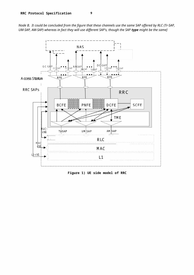
Figure 2) RAN side RRC model
5 RRC Services provided to upper layersThe RRC offers the following services to upper layers, a description of these services is provided in [2].
General Control
Notification
Dedicated control
6 Services expected from lower layers
6.1 Services expected from Layer 2 RLC connection establishment/release. This service performs establishment/release of RLC connections.
Transparent data transfer. This service transmits higher layer PDUs without adding any protocol information, possibly including segmentation/reassembly functionality.
Unacknowledged data transfer. This service transmits higher layer PDUs without guaranteeing delivery to the peer entity. The unacknowledged data transfer mode has the following characteristics:
Detection of erroneous data: The RLC sublayer shall deliver only those SDUs to the receiving higher layer that are free of transmission errors by using the sequence-number check function.
9 RRC Protocol Specification

Unique delivery: The RLC sublayer shall deliver each SDU only once to the receiving upper layer using duplication detection function.
Immediate delivery: The receiving RLC sublayer entity shall deliver a SDU to the higher layer receiving entity as soon as it arrives at the receiver.
Acknowledged data transfer. This service transmits higher layer PDUs and guarantees delivery to the peer entity. In case RLC is unable to deliver the data correctly, the user of RLC at the transmitting side is notified. For this service, both in-sequence and out-of-sequence delivery are supported. In many cases a higher layer protocol can restore the order of its PDUs. As long as the out-of-sequence properties of the lower layer are known and controlled (i.e. the higher layer protocol will not immediately request retransmission of a missing PDU) allowing out-of-sequence delivery can save memory space in the receiving RLC. The acknowledged data transfer mode has the following characteristics:
Error-free delivery: Error-free delivery is ensured by means of retransmission. The receiving RLC entity delivers only error-free SDUs to the higher layer.
Unique delivery: The RLC sublayer shall deliver each SDU only once to the receiving upper layer using duplication detection function.
In-sequence delivery: RLC sublayer shall provide support for in-order delivery of SDUs, i.e., RLC sublayer should deliver SDUs to the receiving higher layer entity in the same order as the transmitting higher layer entity submits them to the RLC sublayer.
Out-of-sequence delivery: Alternatively to in-sequence delivery, it shall also be possible to allow that the receiving RLC entity delivers SDUs to higher layer in different order than submitted to RLC sublayer at the transmitting side.
QoS setting. The retransmission protocol shall be configurable by layer 3 to provide different levels of QoS. This can be controlled.
Notification of unrecoverable errors. RLC notifies the upper layer of errors which cannot be resolved by RLC itself by normal exception handling procedures. e.g. by adjusting the maximum number of retransmissions according to delay requirements
Reallocation of radio resources and MAC parameters. This service performs on request of RRC execution of radio resource reallocation and change of MAC parameters, i.e. reconfiguration of MAC functions such as change of identity of UE, change of transport format (combination) sets, change of transport channel type. resource allocation can be handled by the MAC autonomously.
Reporting of measurements. Local measurements such as traffic volume, quality indication, MAC status indication, [other MAC measurements tbd.], are reported to RRC.
The following potential services are regarded as further study items:
Multicast delivery of higher layer messages. It is left for further study whether or not special functionality on RLC is needed for support of acknowledged transfer of user data to a specified group of UEs.
6.2 Services expected from Layer 1 Measurement results reporting
The contents of this subclause left ffs
7 Functions of RRCThe RRC performs the functions listed below:
Broadcast of information provided by the non-access stratum (Core Network).
Broadcast of information related to the access stratum.
10 RRC Protocol Specification

Establishment, maintenance and release of an RRC connection between the UE and RAN.
Establishment, reconfiguration and release of Radio Access Bearers
Assignment, reconfiguration and release of radio resources for the RRC connection.
RRC connection mobility functions.
Arbitration of the radio resource allocation between the cells.
Control of requested QoS.
UE measurement reporting and control of the reporting.
Control of ciphering.
Slow DCA.
ODMA related function (optional), which includes:
- Broadcast of ODMA relay node neighbour information
- Collation of ODMA relay nodes neighbour lists and gradient information
- Maintenance of number of ODMA relay node neighbours
- Establishment, maintenance and release of a route between ODMA relay nodes
- Interworking between the Gateway ODMA relay node and the RAN
Contention resolution
Paging/notification.
Initial cell selection and re-selection in idle mode.
Arbitration of radio resources on uplink DCH
RRC message integrity protection
Location/Position related processing
The following functions are regarded as further study items:
Congestion control.
Routing of higher layer PDU's (in UE side to correct higher layer entity and in RAN side to correct RANAP entity).
8 Elementary RRC proceduresThis section describes elementary RRC procedures used in the idle mode and in the connected mode. More description on the different UE modes is provided in [2].This section also describes procedures for establishing and releasing an RRC connection.
11 RRC Protocol Specification
8.1 Idle mode procedures
8.1.1 Paging
Figure 3) Paging procedure
This procedure is used to broadcast a PAGING TYPE 1 message from the network to selected UEs which are in idle mode.Only UEs which listen to the correct paging group can be reached by this procedure. The PAGING TYPE 1 message can be sent to either one or many UEs at the same time.
[Note, the following is FFS]: The PAGING TYPE 1 message includes BCCH Modification Information, which indicates the modification of the System Information on BCCH. The coding of BCCH Modification Information is FFS.
[Note: The addresses which are to be used in the paging message (eg IMUI etc) are still to be defined]
[Note: The number of addresses to be used in the paging message needs to be defined]
[Note: the requirement to have different paging messages for RAN originated and CN originated RRC connected mode paging needs to be confirmed]
8.1.2 Notification
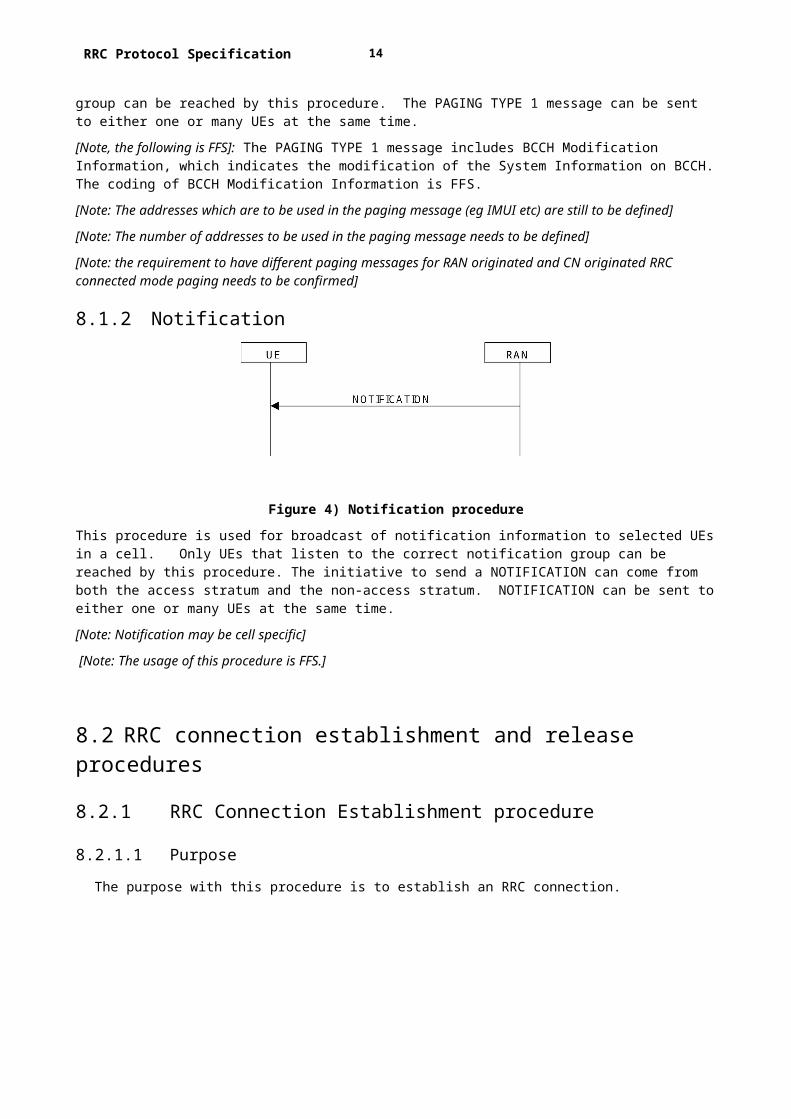
Figure 4) Notification procedure
This procedure is used for broadcast of notification information to selected UEs in a cell. Only UEs that listen to the correct notification group can be reached by this procedure. The initiative to send a NOTIFICATION can come from both the access stratum and the non-access stratum. NOTIFICATION can be sent to either one or many UEs at the same time.
[Note: Notification may be cell specific]
[Note: The usage of this procedure is FFS.]
12 RRC Protocol Specification

8.2 RRC connection establishment and release procedures
8.2.1 RRC Connection Establishment procedure
8.2.1.1 Purpose
The purpose with this procedure is to establish an RRC connection.
Figure 5a) RRC Connection Establishment,accepts
Figure 5b) RRC Connection Establishment, rejects
8.2.1.2 Initiation
The non-access stratum in the UE may request establishment of an RRC connection.
The UE shall transmit an RRC CONNECTION REQUEST message on the uplink CCCH, reset counter V300, and start timer T300.
8.2.1.2.1 Message RRC CONNECTION REQUEST contents to set
The UE may set the IE “Establishment cause” according to indications from the non-access stratum.
The UE shall set the IE “Initial UE identity” according to subclause 8.2.1.11.
The UE shall indicate its capability in the IE “Initial UE capability”.
The UE shall include an intra-frequency measurement report, as instructed to do so in the system information.
8.2.1.3 Reception of RRC CONNECTION REQUEST by the RAN
RAN shall either
13 RRC Protocol Specification
start timer T350 and transmit an RRC CONNECTION SETUP on the downlink CCCH or
transmit an RRC CONNECTION REJECT on the downlink CCCH. On the RAN side, the procedure ends and all context information for this UE may be deleted in RAN.
8.2.1.3.1 Message RRC CONNECTION SETUP contents to set
The IE “Initial UE identity” shall be set to the same value as in the received message RRC CONNECTION REQUEST.
[Editor’s note: Other IEs are included and set according to selection by the RAN.]
8.2.1.3.2 Message RRC CONNECTION REJECT contents to set
The IE “Initial UE identity” shall be set to the same value as in the received message RRC CONNECTION REQUEST.
8.2.1.4 Reception of RRC CONNECTION SETUP by the UE
The UE shall compare the value of the IE “Initial UE identity” in the received RRC CONNECTION SETUP message with the value of the IE “Initial UE identity” in the most recent RRC CONNECTION REQUEST message sent by the UE.
If the values are identical, the UE shall stop timer T300, perform the actions according to 8.2.1.4.1 and transmit an RRC CONNECTION SETUP COMPLETE message on the uplink DCCH. When the RRC CONNECTION SETUP message has been successfully transmitted the procedure ends.
If the values are different, the UE shall ignore the rest of the message
8.2.1.4.1 Message RRC CONNECTION SETUP contents to use
The UE shall
store the values of the IEs “S-RNTI” and “SRNC identity” and
initiate the signalling link parameters according to the IEs “Signalling link type” and “RB multiplexing info”.
If the IE C-RNTI is included, the UE shall
use that C-RNTI on common transport channels in the current cell.
If neither the IEs “PRACH info” nor “Uplink DPCH info” is included, the UE shall
let the physical channel of type PRACH that is given in system information to be the default in uplink for RACH
If neither the IEs “Secondary CCPCH info” nor “Downlink DPCH info” is included, the UE shall
start to receive the physical channel of type Secondary CCPCH that is given in system information to be used as default by FACH, and enter the CELL_FACH state.
Actions that shall be performed by the UE for other IEs are specified in subclause 8.2.1.10.
8.2.1.4.2 Message RRC CONNECTION SETUP COMPLETE contents to set
The UE shall include its capabilities in the RRC CONNECTION SETUP COMPLETE message, according to instructions in the system information.
8.2.1.5 Abnormal cases: DPCH failure or T300 timeout
Upon expiry of timer T300, or
if the UE failed to establish the DPCH(s) indicated in the message RRC CONNECTION SETUP
the UE shall check the value of V300, and
if V300 is smaller or equal than N300, the UE shall transmit a new RRC CONNECTION REQUEST message on the uplink CCCH, restart timer T300 and increase counter V300. The UE shall set the IEs in the RRC CONNECTION REQUEST message according to subclause 8.2.1.2.1.
If V300 is greater than N300, the UE shall enter idle mode. The procedure ends and a connection failure may be
14 RRC Protocol Specification

indicated to the non-access stratum. Other actions the UE shall perform when entering idle mode from connected mode are specified in subclause 8.2.1.9.
8.2.1.6 Reception of RRC CONNECTION REJECT by the UE
When the UE receives an RRC CONNECTION REJECT message on the downlink CCCH, it shall compare the value of the IE “Initial UE identity” in the received RRC CONNECTION SETUP message with the value of the IE “Initial UE identity” in the last RRC CONNECTION REQUEST message sent by the UE.
If the values are identical, the UE shall stop timer T300 and perform the actions in subclause 8.2.1.6.1.
If the values are different, the UE shall ignore the rest of the message
8.2.1.6.1 Message RRC CONNECTION REJECT contents to use
If the IE “wait time” is present, and
if V300 is smaller or equal than N300, the UE shall wait at least the time stated in the IE “wait time”, transmit a new RRC CONNECTION REQUEST message on the uplink CCCH, restart timer T300 and increase counter V300. UE shall set the IEs in the RRC CONNECTION REQUEST message according to subclause 8.2.1.2.1.
If V300 is greater than N300 the UE shall enter idle mode. The procedure ends and a connection failure may be indicated to the non-access stratum. Other actions the UE shall perform when entering idle mode from connected mode are specified in subclause 8.2.1. 9.
If the IE “wait time” is not present the UE shall
enter idle mode. The procedure ends and a connection failure may be indicated to the non-access stratum. Other actions the UE shall perform when entering idle mode from connected mode are specified in subclause 8.2.1. 9.
8.2.1.7 Reception of RRC CONNECTION SETUP COMPLETE by the RAN
When RAN has received the RRC CONNECTION SETUP COMPLETE message, the procedure ends on the RAN side, and timer T350 shall be stopped.
8.2.1.8 Abnormal case: T350 timeout
Upon expiry of timer T350, the procedure ends on the RAN side, and all context information for this UE may be deleted in RAN.
8.2.1.9 Actions when entering idle mode from connected mode
FFS
8.2.1.10 Actions when entering CELL_DCH state
FFS
8.2.1.11 Selection of initial UE identity
FFS
15 RRC Protocol Specification

8.2.2 RRC Connection Release
Figure 6) RRC Connection release procedure
A normal RRC connection release procedure is initiated from the RAN, e.g. when the last Signaling Connection is released. [Note: Release in case of RRC connection failure is FFS.] [Note: Possibility for UE initiated RRC connection release is FFS.]
Two variants of this procedure have been identified:
a) RRC connection release from state where dedicated physical channel is available
b) RRC connection release from state where there is no dedicated physical channel
In the former case (a) the RAN sends an RRC CONNECTION RELEASE message to the UE using acknowledged mode on the DCCH. The UE then leaves the Connected Mode and initiates release of the layer 2 signalling link. The RRC Connection Release procedure ends when all UE dedicated resources (such as radio resources and radio access bearers) tied to the RRC connection are released and the RRC layer is transferred to idle mode.
In the latter case (b) the RRC layer entity in the network issues an RRC CONNECTION RELEASE message using unacknowledged mode on the DCCH. Upon reception of this message the UE-RRC sends an RRC CONNECTION RELEASE COMPLETE message to RAN using acknowledged mode on the DCCH. [Note: Depending on RLC design, the acknowledgement to RRC CONNECTION RELEASE could be piggybacked to the RRC CONNECTION RELEASE COMPLETE MESSAGE, resulting in no additional messages. Therefore acked / unacked transmission is considered FFS.]. After receiving the RRC CONNECTION RELEASE COMPLETE message the network RRC layer releases L2 resources and the RRC entity dedicated to this UE goes to Idle Mode.
In both cases the RRC CONNECTION RELEASE COMPLETE message may be sent one or several (up to N) times using Layer 3 (RRC) quick repeat. This is indicated by the dashed lines in Fig.7
8.2.3 RRC Connection re-establishment
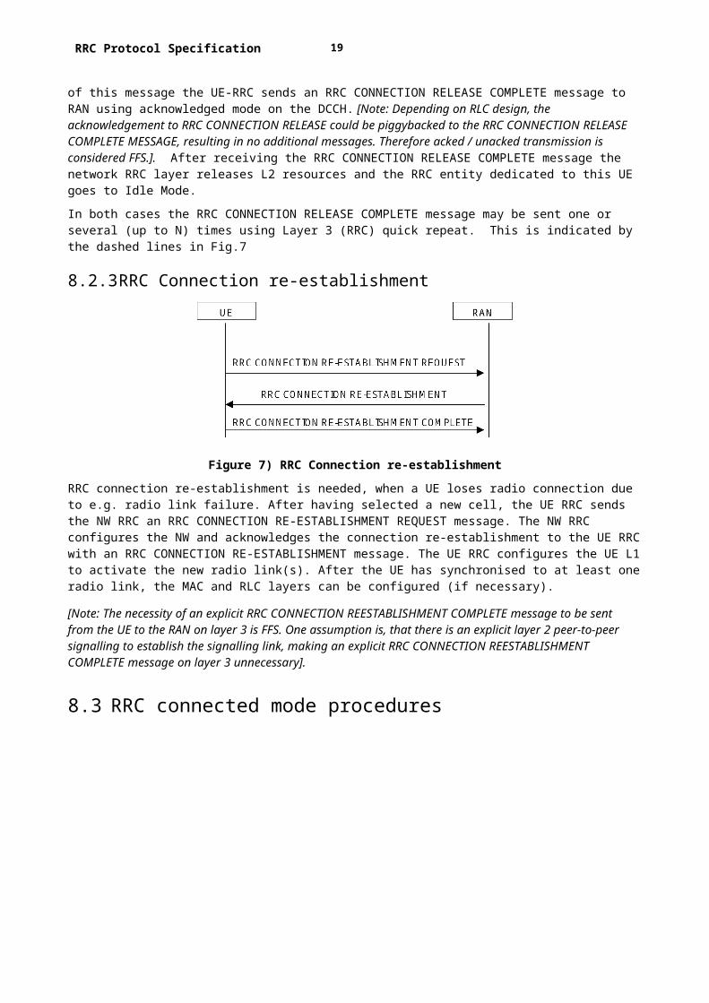
Figure 7) RRC Connection re-establishment
RRC connection re-establishment is needed, when a UE loses radio connection due to e.g. radio link failure. After having selected a new cell, the UE RRC sends the NW RRC an RRC CONNECTION RE-ESTABLISHMENT REQUEST message. The NW RRC configures the NW and acknowledges the connection re-establishment to the UE RRC with an RRC CONNECTION RE-ESTABLISHMENT message. The UE RRC configures the UE L1 to activate
16 RRC Protocol Specification
the new radio link(s). After the UE has synchronised to at least one radio link, the MAC and RLC layers can be configured (if necessary).
[Note: The necessity of an explicit RRC CONNECTION REESTABLISHMENT COMPLETE message to be sent from the UE to the RAN on layer 3 is FFS. One assumption is, that there is an explicit layer 2 peer-to-peer signalling to establish the signalling link, making an explicit RRC CONNECTION REESTABLISHMENT COMPLETE message on layer 3 unnecessary].
8.3 RRC connected mode procedures
8.3.1 Radio Bearer Related Procedures
8.3.1.1 Radio Bearer Establishment
Figure8) Radio Bearer Establishment Procedure
This procedure establishes a new radio bearer. The establishment includes, based on QoS, assignment of RLC parameters, multiplexing priority for the DTCH, scheduling priority for DCH, TFS for DCH and update of TFCS. It may also include assignment of a physical channel(s) and change of the used transport channel types / RRC state.
There are a number of alternative methods by which radio access bearers may be established:
a) Radio Bearer Establishment with Dedicated Physical Channel Activation
b) Radio Bearer Establishment with Unsynchronised Dedicated Physical Channel Modification
c) Radio Bearer Establishment with Synchronised Dedicated Physical Channel Modification
d) Radio Bearer Establishment without Dedicated Physical Channel
A Radio Bearer Establishment is initiated when the RRC layer in the network sends a RADIO BEARER SETUP message to its peer entity. This message contains L1, MAC and RLC parameters and in the synchronised case an activation time. RRC on the UE side then configures L1 and MAC and creates a new RLC entity associated with the new radio bearer. A similar reconfiguration is also done on the network side. The UE then sends a RADIO BEARER SETUP COMPLETE message back to the network.
[Note: The possibility of establishing multiple radio bearers within one message is FFS]
17 RRC Protocol Specification

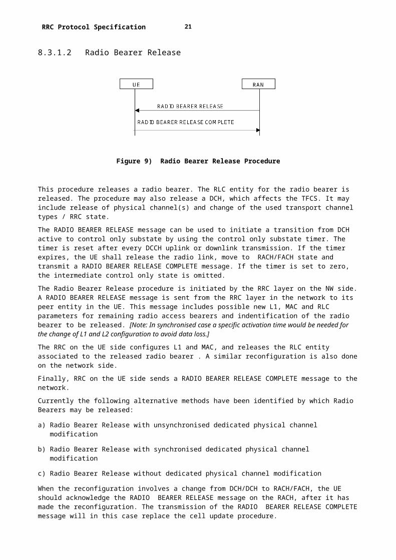
8.3.1.2 Radio Bearer Release
Figure 9) Radio Bearer Release Procedure
This procedure releases a radio bearer. The RLC entity for the radio bearer is released. The procedure may also release a DCH, which affects the TFCS. It may include release of physical channel(s) and change of the used transport channel types / RRC state.
The RADIO BEARER RELEASE message can be used to initiate a transition from DCH active to control only substate by using the control only substate timer. The timer is reset after every DCCH uplink or downlink transmission. If the timer expires, the UE shall release the radio link, move to RACH/FACH state and transmit a RADIO BEARER RELEASE COMPLETE message. If the timer is set to zero, the intermediate control only state is omitted.
The Radio Bearer Release procedure is initiated by the RRC layer on the NW side. A RADIO BEARER RELEASE message is sent from the RRC layer in the network to its peer entity in the UE. This message includes possible new L1, MAC and RLC parameters for remaining radio access bearers and indentification of the radio bearer to be released. [Note: In synchronised case a specific activation time would be needed for the change of L1 and L2 configuration to avoid data loss.]
The RRC on the UE side configures L1 and MAC, and releases the RLC entity associated to the released radio bearer . A similar reconfiguration is also done on the network side.
Finally, RRC on the UE side sends a RADIO BEARER RELEASE COMPLETE message to the network.
Currently the following alternative methods have been identified by which Radio Bearers may be released:
a) Radio Bearer Release with unsynchronised dedicated physical channel modification
b) Radio Bearer Release with synchronised dedicated physical channel modification
c) Radio Bearer Release without dedicated physical channel modification
When the reconfiguration involves a change from DCH/DCH to RACH/FACH, the UE should acknowledge the RADIO BEARER RELEASE message on the RACH, after it has made the reconfiguration. The transmission of the RADIO BEARER RELEASE COMPLETE message will in this case replace the cell update procedure.
The RAN may optionally include PRACH/SCCPCH parameters and the c-RNTI for one or many cells in the RADIO BEARER RELEASE message.
[Note: The details of handling other types of substate transitions is FFS]
[Note: The possibility of releasing multiple radio bearers within one message is FFS]
18 RRC Protocol Specification
8.3.1.3 Radio Bearer and signalling link Reconfiguration
Figure10 ) Radio Bearer and signalling link Reconfiguration Procedure
This procedure reconfigures parameters for a radio access bearer or the signalling link to reflect a change in QoS. It may include change of RLC parameters, change of multiplexing priority for DTCH/DCCH, change of DCH scheduling priority, change of TFS for DCH, change of TFCS, assignment or release of physical channel(s) and change of used transport channel types.
Currently identified options by which Radio Access Bearers may be reconfigured:
a) Synchronised Radio Bearer reconfiguration
b) Unsynchronised Radio Bearer reconfiguration
[Note: When the reconfiguration involves a change of transport channel (eg. from DCH/DCH to RACH/FACH), it is FFS, whether the UE should acknowledge the RADIO BEARER RECONFIGURATION message before making the reconfiguration (eg. on the DCH) or after making the reconfiguration (eg. on the RACH)]
[Note: The possibility of reconfiguring multiple radio bearers and signalling links within one message is FFS]
8.3.2 Transport Channel Reconfiguration
Figure11) Procedure for transport channel reconfiguration
This procedure configures parameters related to a transport channel such as the TFS. The procedure also assigns a TFCS and may change physical channel parameters to reflect a reconfiguration of a transport channel in use.
The TRANSPORT CHANNEL RECONFIGURATION message can be used to initiate the control only substate by using the control only substate timer. The timer is reset after every DCCH uplink or downlink transmission. If the timer expires, the UE shall release the radio link, move to RACH/FACH state and transmit a TRANSPORT CHANNEL RECONFIGURATION COMPLETE message. If the timer is set to zero, the intermediate control only state is omitted.
A change of the transport format set for a transport channel is triggered in the RRC layer in the network. A TRANSPORT CHANNEL RECONFIGURATION message is then sent from the RRC layer in the network to its peer entity. This message contains the new transport format set, a new transport format combination Set and may include physical channel parameters, i.e. new parameters for L1 and MAC. [Note1: In a synchronised procedure a specific activation time is needed for the change of L1 and L2 configuration to avoid data loss.] When this message is received in the UE a reconfiguration of L1 and MAC is done. A similar reconfiguration is also done on the network side. Finally, a TRANSPORT CHANNEL RECONFIGURATION COMPLETE message is returned to the network.
Currently identified options by which transport channels may be reconfigured:
19 RRC Protocol Specification

a) Synchronised transport format set reconfiguration
b) Unsynchronised transport format set reconfiguration
c) Pre-configuration of TFS/TFCS for a transport channel not yet in use
When the reconfiguration involves a change from DCH/DCH to RACH/FACH, the UE should acknowledge the TRANSPORT CHANNEL RECONFIGURATION message on the RACH, after it has made the reconfiguration. The transmission of the TRANSPORT CHANNEL RECONFIGURATION COMPLETE message will in this case replace the cell update procedure.
The RAN may optionally include PRACH/SCCPCH parameters and the c-RNTI for one or many cells in the TRANSPORT CHANNEL RECONFIGURATION message.
[Note: The details of handling other types of substate transitions is FFS]
[Note: The possibility of reconfiguring multiple transport channels within one message is FFS]
8.3.3 Transport Format Combination Control
Figure12) Transport Format Combination Control Procedure
The network uses this procedure to control which transport format combinations (within the transport format combination set) can be used by the UE in the uplink. An example of when this procedure might be used is when a congestion situation occurs such that it is desirable to temporarily restrict the TFC's in use.
This procedure is initiated with a TRANSPORT FORMAT COMBINATION CONTROL message sent from the network to the UE. This message defines the subset of the complete Transport Format Combination Set which the UE is allowed to use, or in case of relieving a temporary restriction, a TFCS which is identical to the complete original set. The UE then reconfigures MAC which thereafter uses the new TFC set. The TRANSPORT FORMAT COMBINATION CONTROL message may be sent as unacknowledged data transfer (FFS) since it is assumed that it does not matter if one UE out of many misses this information and stays with the old TFCS.
8.3.4 Physical Channel Reconfiguration
8.3.4.1 Physical channel Reconfiguration
Figure13) Physical Channel Reconfiguration procedure
20 RRC Protocol Specification
This procedure may assign, replace or release a set of physical channels used by an UE. As a result of this, it may also change the used transport channel type (and RRC state). For example, when the first physical channel is assigned the UE enters the DCH/DCH state. When the last physical channel is released the UE leaves the DCH/DCH state and enters a state (and transport channel type) indicated by the network. A special case of using this procedure is to change the DL channelization code of a dedicated physical channel. [Note: The procedure does not change the active set, in the downlink the same number of physical channels are added or replaced for each radio link.]
Currently identified motivations for using this procedure (methods by which physical channels may be reconfigured):
a) Assignment of dedicated physical channel (switch from common channels to dedicated physical channel)
b) Synchronised replacement (modification) of dedicated physical channel (eg. for D/L code tree re-organisation)
c) Release dedicated physical channel (switch from dedicated physical channel to common channels).
When the reconfiguration involves a change from DCH/DCH to RACH/FACH, the UE should acknowledge the PHYSICAL CHANNEL RECONFIGURATION message on the RACH, after it has made the reconfiguration. The transmission of the PHYSICAL CHANNEL RECONFIGURATION COMPLETE message will in this case replace the cell update procedure.
The RAN may optionally include PRACH/SCCPCH parameters and the c-RNTI for one or many cells in the PHYSICAL CHANNEL RECONFIGURATION message for one or many cells.
8.3.5 Mobility Related Procedures
8.3.5.1 Modification of the active set when in hand-over
Figure14) Procedure for modifying the active set when in soft hand-over
There are three alternative ways of modifying the active set which have been identified:
a) Radio link addition
b) Radio link removal
c) Combined radio link addition and removal
Radio link addition is triggered in the network RRC layer. The NW RRC first configures the new radio link. Transmission and reception begin immediately. The NW RRC then sends an ACTIVE SET UPDATE message to the UE RRC. The UE RRC configures layer 1 to begin reception. After confirmation from the physical layer in UE an ACTIVE SET UPDATE COMPLETE message is sent to the NW RRC
Radio link removal is triggered by the network RRC layer. The radio link is first deactivated by the UE and then in the NW. The NW RRC sends an ACTIVE SET UPDATE message to the UE RRC. The UE RRC requests UE L1 to terminate reception of the radio link(s) to be removed. After this the UE RRC acknowledges radio link removal with an ACTIVE SET UPDATE COMPLETE message to the NW RRC. The NW RRC proceeds to request the NW L1 to release the radio link.
The NW RRC determines the need for radio link replacement. When radio links are to be replaced, the NW RRC first configures the NW L1 to activate the radio link(s) that are being added. The NW RRC then sends an ACTIVE SET UPDATE message to the UE RRC, which configures the UE L1 to terminate reception on the removed radio link(s) and begin reception on the added radio link(s). If the UE active set is full, an old radio link has to be removed before a new one can be added. If the UE has only one radio link, then the replacement must be done in reverse
21 RRC Protocol Specification

order (first add, then remove). Note: The present assumption is that the order of the replacement can be left to the UE. The UE RRC acknowledges the replacement with an ACTIVE SET UPDATE COMPLETE message. The NW RRC then configures the NW L1 to terminate reception and transmission on the removed radio link.
[Editors note: Presumably the radio link replacement procedure can be used for inter-frequency(make before break) hard handover]
8.3.5.3 Inter system hard hand-over (GSM/BSS to RAN)
Figure15) Procedure for Inter-system hard hand-over - GSM to RAN
The handover from GSM/BSS to RAN for a dual-mode GSM MS / UMTS UE is described.
On the network side, the RRC layer performs admission control and radio resource allocation, assigning an RNTI for the RRC connection and selecting radio resource parameters (such as transport channel type, transport format sets, etc).
The selected parameters including the RNTI, are transmitted to the UE via the upgraded GSM RR message HANDOVER COMMAND. Upon reception of the HANDOVER COMMAND message, the UE RRC configures L1 and L2 using these parameters to locally establish the DCCH logical channel . Layer 1 indicates to RRC when it has reached synchronisation. An RLC signalling link establishment is then initiated by the UE. A HANDOVER COMPLETE message is finally sent by the UE RRC.
8.3.5.4 Inter system hard hand-over (RAN to GSM/BSS, PSTN/ISDN domain services)
22 RRC Protocol Specification

Figure16) Inter system hard hand-over (RAN to GSM/BSS), PSTN/ISDN services, successful case
[Note: The scope of this description is restricted to a UE having a connection only to PSTN/ISDN services, i.e. no simultaneous IP connection]
For PSTN/ISDN domain services RAN Inter-System Handover procedure is initiated from the RAN.
The RAN RRC sends an INTER-SYSTEM HANDOVER COMMAND (type:RAN-to-BSS HARD HANDOVER) to the UE to start the execution of the handover. This message contains all the information needed for the UE to be able to switch to the GSM cell and perform a GSM handover.
Upon reception of the HANDOVER COMMAND message, the UE RRC layer can then locally release the resources on the RLC, MAC and physical layers of the UE.
After having switched to the assigned GSM channel specified in the INTER-SYSTEM HANDOVER COMMAND, the MS RR sends a HANDOVER ACCESS message in successive layer 1 frames, just as it typically would have done for a conventional GSM handover initiation.
When the BSS-RR has received the HANDOVER ACCESS it indicates this to the CN/AS by sending a HANDOVER DETECT message. The BSS-RR sends a PHYSICAL INFORMATION message to the GSM MS in unacknowledged mode that contains various fields of physical layer -related information allowing a proper transmission by the MS.
After layer 1 and layer 2 connections are successfully established, the GSM MS returns the HANDOVER COMPLETE message.
The RAN is then able to release the resources that were used by the UE in RAN Connected Mode.
If the UE is unable to execute the Inter-System Handover or if low layer failure happens on the UE side on the GSM/BSS channel before HANDOVER COMPLETE has been sent, the UE deactivates the new GSM/BSS channel and reactivates the RAN connection.
The UE then sends a INTER-SYSTEM HANDOVER FAILURE message and resumes normal operation as if no Inter-System Handover have occurred.
8.3.5.5 Inter system cell reselection (RAN to GSM/GPRS, IP domain services)
For IP domain services, intersystem cell reselection from RAN to GSM/GPRS is initiated by the UE, or ordered by the network with the INTER-SYSTEM HANDOVER COMMAND message.
23 RRC Protocol Specification

8.3.5.6 Inter system cell reselection (GSM/GPRS to RAN, IP domain services)
For IP domain services, intersystem cell reselection from GSM/GPRS to RAN is initiated by the UE or by GSM/BSS according to GSM/GPRS specifications.
8.3.5.7 RRA update
Figure17) RRA update procedure.
The RRA update procedure is normally used by the UE to inform the RAN that the UE has switched to a new RRA. In that case the procedure is triggered after change of cell and after the UE have read information broadcasted by RAN indicating change of RRA. The procedure can also be triggered by expiry of a RRA update periodicity timer in the UE.
The UE establishes a radio link to a cell in the new RRA. After that the UE sends a RRA UPDATE message to the RAN. Upon reception of the message the RAN registers the change of RRA, and sends a RRA UPDATE CONFIRM message to the UE. The RRA UPDATE CONFIRM message may include a new C-RNTI and/or S-RNTI plus SRNC identity. The RRA UPDATE CONFIRM message may also contain new NAS system information.
[Note1: Whether it should be possible for the RAN to trigger a RRA update request from the UE is FFS.]
8.3.5.8 Cell update procedure
8.3.5.8.1 Purpose
The main purpose of the cell update procedure is to update RAN with the current cell of the UE after cell reselection in CELL_FACH or CELL_PCH state. It may also be used for supervision of the RRC connection, even if no cell reselection takes place. The cell update procedure can also be used to re-configure the c-plane AM_RLC. UE can use CELL UPDATE message to notify the unrecoverable error in AM_RLC on c-plane [Note 1].
[Note 1: The RRC Connection re-establishment procedure can also be used in some cases]
24 RRC Protocol Specification
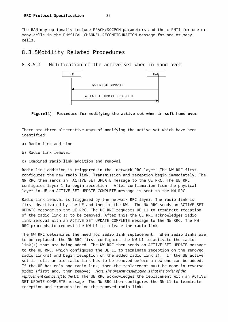
Figure18a) Cell update procedure, basic flow
Figure18b) Cell update procedure with RNTI reallocation
Figure 18c) Cell update procedure with physical channel reconfiguration
[Editor's note: Physical channel reconfiguration complete is only used when common channels are configured (doesn't apply to dedicated channels)]
8.3.5.8.2 Initiation
8.3.5.8.2.1 Cell update due to cell reselection
When the UE is in CELL_FACH or CELL_PCH state and originates from an cell and makes a successful reselection of another cell, it shall
move to CELL_FACH state, if not already in that state
transmit a CELL UPDATE message on the uplink CCCH,
start timer T302 and reset counter V302
The IE “cell update cause” shall be set to “cell reselection”.
25 RRC Protocol Specification

8.3.5.8.2.2 Cell update due to periodic cell update
When the UE is in CELL_RACH or CELL_PCH state, the UE shall perform periodic cell updating according to the system information. The timer T305 shall be reset when entering CELL_RACH state and after each uplink message transmission in CELL_RACH state.
Upon expiry of timer T305, the UE shall
move to CELL_FACH state, if not already in that state
transmit a CELL UPDATE message on the uplink CCCH,
start timer T302 and reset counter V302
restart timer T305
The IE “Cell update cause” shall be set to “periodic cell update”.
8.3.5.8.2.3 Message CELL UPDATE contents to set
The IE “Cell update cause” shall be set to the event causing the transmission of the CELL UPDATE message, see subclauses 8.3.5.8.2.1 and 8.3.5.8.2.2.
The UE shall include an intra-frequency measurement report in the CELL UPDATE message, when instructed to do so in the system information.
8.3.5.8.3 Reception of CELL UPDATE by the UTRAN
When the UTRAN receives a CELL UPDATE message, it shall transmit a CELL UPDATE CONFIRM message on the downlink DCCH.
When the UTRAN detects AM_RLC error, it waits for CELL UPDATE message from the UE and when the UTRAN receives it, UTRAN commands the UE to re-configure AM_RLC by sending CELL UPDATE CONFIRM message. This procedure can be used not only in the case of AM_RLC error but also in the case that UTRAN wants to re-configure AM_RLC for other reasons such as in the case when SRNC Relocation is initiated without keeping RLC status (current counters) from old SRNC to new SRNC.
8.3.5.8.3.1 Message CELL UPDATE CONFIRM contents to set
UTRAN shall use the same S-RNTI and SRNC identity for the transmission of CELL UPDATE CONFIRM as the values of the IEs “S-RNTI” and “SRNC identity” in the received message CELL UPDATE.
UTRAN may allocate a new C-RNTI and/or a new S-RNTI plus SRNC identity for the UE. In that case UTRAN shall include those new identities in the IEs “new C-RNTI”, “new S-RNTI” and “new SRNC identity”, and start timer T361.
UTRAN may allocate new PRACH and/or Secondary CCPCH to the UE. In that case UTRAN shall include the IEs “PRACH info” and/or “Secondary CCPCH info”. UTRAN shall start timer T357.
8.3.5.8.4 Reception of CELL UPDATE CONFIRM by the UE
When the UE receives a CELL UPDATE CONFIRM message on the downlink DCCH, it shall stop timer T302.
8.3.5.8.4.1 Message CELL UPDATE CONFIRM contents to use
If the CELL UPDATE CONFIRM message includes the IEs “new C-RNTI” and optionally “new S-RNTI” and “new SRNC identity”, the UE shall
update its identities and transmit an RNTI REALLOCATION COMPLETE message on the uplink DCCH. The procedure ends when the UE has transmitted that message and the UE shall go back to CELL_PCH state if the cell update procedure was initiated from that state.
If the CELL UPDATE CONFIRM message includes the IE “RRA update indicator”, the UE shall
enter RRA_PCH state, after all other possible actions. If the CELL UPDATE CONFIRM message also includes the IE “RRA-Id” the UE shall store this RRA identity.
If the CELL UPDATE CONFIRM message includes the IEs “PRACH info” and/or “Secondary CCPCH info”, but not the IEs “new C-RNTI”, “new S-RNTI” nor “new SRNC identity”, the UE shall
26 RRC Protocol Specification

Perform the actions stated in subclauses x and y [Editor’s note: a reference to general actions for these IEs.]
transmit a PHYSICAL CHANNEL RECONFIGRRATION COMPLETE message on the uplink DCCH. The procedure ends when the UE has transmitted that message and the UE shall go back to CELL_PCH state if the cell update procedure was initiated from that state.
If the CELL UPDATE CONFIRM message includes the IEs “PRACH info” and/or “Secondary CCPCH info”, and at least one of the IEs “new C-RNTI”, “new S-RNTI” or “new SRNC identity”, the UE shall
Perform the actions stated in subclauses x and y [Editor’s note: a reference to general actions for these IEs.]
If the CELL UPDATE CONFIRM message includes the IEs “CN domain identity” and “NAS system information”, the UE shall forward the content of the IE to the non-access stratum entity of the UE indicated by the IE “CN domain identity”.
If the CELL UPDATE CONFIRM message includes the neither the IEs “PRACH info”, “Secondary CCPCH info”, “new C-RNTI”, “new S-RNTI” nor “new SRNC identity”, the procedure ends and the UE shall go back to CELL_PCH state if the cell update procedure was initiated from that state.
8.3.5.8.5 Abnormal cases: T302 expiry or cell reselection
Upon expiry of timer T302, and/or
upon reselection of another UTRA cell when waiting for the CELL UPDATE CONFIRM message,
the UE shall check the value of V302 and
If V302 is smaller or equal than N302, the UE shall retransmit a CELL UPDATE message on the uplink CCCH, restart timer T302 and increase counter V302. The UE shall set the IEs in the CELL UPDATE message according to subclause 8.3.5.8.2.
If V302 is greater than N302, the UE shall enter idle mode. The procedure ends and a connection failure may be indicated to the non-access stratum. Other actions the UE shall perform when entering idle mode from connected mode are specified in subclause x.x.x.
8.3.5.8.6 Reception of RNTI REALLOCATION COMPLETE by the RAN
See subclause x.x.x [Editor’s note: reference to the corresponding part of RNTI reeallocation procedure to be inserted here]..
8.3.5.8.7 Reception of PHYSICAL CHANNEL RECONFIGURATION COMPLETE by the RAN
FFS
8.3.5.8.8 Abnormal case: T357 expiry
FFS
8.3.5.9 RNTI reallocation procedure
8.3.5.9.1 Purpose
The purpose with this procedure is to allocate a new C-RNTI and/or S-RNTI plus SRNC identity to an UE in connected mode.
27 RRC Protocol Specification
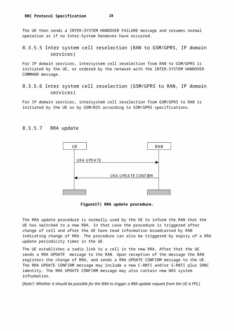
Figure 19) RNTI reallocation procedure, normal flow
8.3.5.9.2 Initiation
The RAN shall transmit an RNTI reallocation message to the UE on the downlink DCCH.
8.3.5.9.3 Reception of RNTI REALLOCATION by the UE
When the UE receives an RNTI REALLOCATION message, it shall take the actions in subclause 8.3.5.9.3.1 and then transmit an RNTI REALLOCATION COMPLETE message on the uplink DCCH. The procedure ends.
8.3.5.9.3.1 Message RNTI REALLOCATION contents to use
If the IEs “new S-RNTI” and “new SRNC identity” are present, the UE shall store and start to use the values of these IEs as the current S-SRNTI and SRNC-identity.
If the IE ”new C-RNTI” is present, the UE shall store and start to use the value of this IE.
If the IEs “CN domain identity” and “NAS system information” are included, the UE shall forward the content of the IE to the non-access stratum entity of the UE indicated by the IE “CN domain identity”.
8.3.5.9.4 Reception of RNTI REALLOCATION by the network
When the network receives RNTI REALLOCATION COMPLETE, UTRAN shall delete any old C-RNTI and S-RNTI and SRNC identity. The procedure ends.
8.3.6 RRC Connected mode procedures which use Paging
8.3.6.1 Core network originated paging
Figure20) Core network originated paging procedure in connected mode
So far only one example of this procedure has been identified (two others are FFS):
a) RAN co-ordinates, UE is on DCCH (PAGING TYPE 2 message is used)
b) RAN co-ordinates, UE is on PCCH (FFS, PAGING TYPE 1 message would be used)
c) UE co-ordinates (FFS)
28 RRC Protocol Specification

Consider case (a): This procedure enables the CN to request paging of a UE. Since the UE can be reached on the DCCH, the RRC layer formats a PAGING TYPE 2 message containing the UE paging identity and the NAS information, and the message is transmitted directly to the UE using unacknowledged data transfer.
[Note: It is FFS whether only one paging message is required (as used for idle mode paging) or whether both Type 1 and Type 2 paging messages are required]
8.3.6.2 RAN originated paging
Figure 21) RAN originated paging procedure in connected mode
The RRC layer in the network can use this procedure to trigger a switch from PCH or RRA connected state to RACH/FACH state. A PAGING TYPE 1 message, containing the S-RNTI and SRNC identity is sent on the PCCH.
In the UE, the RRC layer continuously monitors the paging group on the PCH and compares the UE identities in the received paging messages with its own identities. When a match occurs, the RRC layer uses the cell update procedure to acknowledge the reception of paging and optionally obtain a new C-RNTI.
[Note: It is FFS whether only one paging message is required (as used for idle mode paging) or whether Type 1 and Type 2 paging messages are also required]
8.3.7 Procedures related to measurement and monitoring[Note: The following text needs to be reviewed at the next 3GPP WG2 meeting]
In idle mode, the UE monitors and measures neighboring cells according to information received on BCH.
After sending the initial random access message, the UE may continue measurements using the ‘idle’ mode parameters until a MEASUREMENT CONTROL message is received from the serving RNS. This message indicates the parameters to be used for monitoring in ´connected` state.
Monitored cells are grouped in the UE into three different categories:
1. Cells that belong to the active set. There are at least two cells in this set. The radio link synchronization between the current UE and these cells should be established and corresponding tranffic channels should be kept simutanliously.
2. Cells that are identified as feasible for handover belong to the candidate set. The UE may request that a cell in the candidate set is moved to the active set in a MEASUREMENT REPORT message.
3. Other cells that are known, but not currently feasible for handover, belong to the neighbour set. The UE does not notify the serving RNS when it moves a cell from the candidate set to the neighbour set or from the neighbour set to the candidate set.
From an RRC point of view, the mobile station measurements can be grouped with respect to the type of measurement performed in the mobile station, i.e., what and how the mobile station shall measure. Examples are:
29 RRC Protocol Specification
Radio link measurements: measurements on downlink/uplink direction of radio links in the active set.
Radio signal transport delay difference
Intra-frequency measurements: measurements on downlink physical channels that do not belong to the active set, but have the same frequency as the active set.
Inter-frequency measurements: measurements on downlink physical channels with frequencies that differ from the frequency of the active set.
Inter-system measurements: measurements on downlink physical channels belonging to another radio access system than TD-SCDMA, e.g. WCDMA, or GSM.
Traffic volume measurements: measurements on uplink traffic volume.
Quality measurements: Measurements of quality parameters, e.g. downlink transport block error rate.
Internal measurements: Measurements of UE transmission power and UE received signal level.
A radio link measurement in the mobile station can be used for handover, power control or operation and maintenance purposes in the network. However, it should be possible to have a number of mobile station measurements running in parallel, where each measurement is controlled and reported independently of each other.
The same type of measurements can be used as input to different functions in RAN. For instance, an intra-frequency measurement in the UE can be used for handover, power control or operation and maintenance purposes in the network. However, it should be possible to have a number of UE measurements running in parallel, where each measurement is controlled and reported independently of each other.
Each type of mobile station measurement is associated with a standardised measurement method that can be described with a limited number of parameters (threshold levels, triggering conditions etc) in the measurement control message from the network.
The measurement report to the network can be sent by either acknowledged or unacknowledged data transfer on the DCCH. The acknowledged mode may be employed for e.g. event-triggered measurement reports, while the unacknowledged mode may be used for e.g. periodical reporting with low periodicity. The network indicates (in the UE measurement control message) which reporting alternative the UE should use for the corresponding measurement.
After sending the initial random access message, the UE shall continue measurements performed in idle mode until a MEASUREMENT CONTROL message is received from RAN. This message indicates e.g. the parameters to be used for monitoring in connected mode.
On the DCH, the UE shall report radio link related measurements to the RAN with a MEASUREMENT REPORT message. In order to receive information for the establishment of immediate macrodiversity, the UTRAN may also request the UE to append radio link related measurement reports to the following messages sent on the RACH:
RRC CONNECTION REQUEST sent to establish an RRC connection.
RRC CONNECTION RE-ESTABLISHMENT REQUEST sent to re-establish an RRC connection.
DIRECT TRANSFER sent uplink to establish a signalling connection.
CELL UPDATE sent to respond to a RAN originated page.
MEASUREMENT REPORT sent to report uplink traffic volume.
[Note: Whether or not measured results can be appended to other messages and in other scenarios is FFS.
30 RRC Protocol Specification
8.3.7.1 Measurement control
Figure 22) Measurement Control procedure
This procedure is initiated from the RAN side to control a measurement in a specific UE. The RAN sends a MEASUREMENT CONTROL message to the UE on the DCCH. The message includes the information that controls the UE measurement. Examples of such information are:
1. Measurement type: One of the types from a predefined list where each type describes what the UE shall measure.
2. Measurement identity number: A reference number that is used by the RAN at modification of the measurement and by the UE in the measurement report.
3. Measurement command: One out of three different measurement commands
Setup: Setup a new measurement.
Modify: Modify a previously specified measurement, e.g. change the reporting criteria.
Release: Stop a measurement and clear all information in the UE that are related to that measurement.
4. Measurement objects: The objects the UE shall measure on, and corresponding object information.
5. Measurement quantity: The quantity the UE shall measure. This also includes the filtering of the measurements.
6. Report quantities: The quantities the UE shall include in the report in addition to the quantities that are mandatory to report for the specific event.
7. Measurement reporting criteria: The triggering of the measurement report, e.g. periodical, event-triggered or immediate reporting. Here is also specified if the measurement report should be transmitted using either acknowledged or unacknowledged data transfer on the DCCH.
[Editor's note: Details of how this procedure can make use of slotted mode operation is still under investigation
8.3.7.2 Measurement reporting
Figure 23) Measurement Report procedure
The Measurement Report procedure is initiated from the UE side when the reporting criteria are met. The message is sent using either acknowledged or unacknowledged data transfer on the DCCH. The UE sends a MEASUREMENT REPORT message to the RAN that includes the measurement identity number and the measurement results of the
31 RRC Protocol Specification
mandatory and optional report quantites that were defined in the corresponding MEASUREMENT CONTROL message.
[Note: UE measurement reports can be sent without prior Measurement Control message, e.g. reports of measurements that are predefined in the standard or defined via system information.]
8.3.8 Other procedures in connected mode
8.3.8.1 Transmission of UE capability information
Figure 24) Procedure for transmission of UE capability information
The UE transfers its capability information to the network by transmitting the UE CAPABILITY INFORMATION message on the DCCH. RAN acknowledges the successful update of UE capability by UE CAPABILITY INFORMATION CONFIRM message. This procedure can (optionally) be performed after RRC Connection Setup procedure and also during the lifetime of the RRC Connection if the UE capability information changes (e.g. due to change in UE power class). UE capability information can also explicitly be requested by RAN [Note: The mechanism for this is FFS].
8.3.8.2 Sending of system information in RRC connected mode
Figure 25) Sending of system information to UE in RRC connected mode
The RAN may send dedicated system information messages to the UE in RRC connected mode in order to update e.g. neighbouring cell and MM information. The UE RRC forwards received MM information to the UE MM sublayer.
32 RRC Protocol Specification

The system information messages transmitted in connected mode include different combinations of parameters than system information messages for idle mode MSs. The grouping of system information messages is FFS. Three ways have been identified by which this signalling can be conveyed:
On DCCH
On BCCH [Editors note,the BCCH may be used to convey information to a UE even when a DCCH exists, and the current assumption is that where DCCH exists BCCH is not used]
On CCCH mapped onto a FACH or a ACCH transport channel (provided the ACCH transport channel exists). [Editors note ,the CCCH may be used to convey information to a UE even when a DCCH exists].
8.3.8.3 Direct transfer
Figure 26a) Direct Transfer procedure in uplink
Figure 26b) Direct Transfer procedure in downlink
The direct transfer procedure is used to carry all higher layer (NAS) messages over the radio interface. The DIRECT TRANSFER message includes the higher layer (NAS) message as payload and a CN domain identifier of the destination (in uplink) or originating (in downlink) core network node.
The DIRECT TRANSFER message is used both in uplink and in downlink.
33 RRC Protocol Specification

Upon reception of the DIRECT TRANSFER message the higher layer PDU is routed – using the CN domain identifier parameter – in UE side to correct higher layer entity and in RAN side to correct CN domain.
8.3.8.4 RRC status procedure
Figure 27): RRC status procedure
[Note: The following describes the use of the RRC status procedure for release of signalling connection. Other use of this procedure is FFS.]
If a UE has signalling connections to CN1 and CN2, one of the nodes may request the RAN to release the RRC connection. In this case the RAN needs to inform the corresponding MM entity in the UE – without releasing the RRC connection - that the signalling connection has been released, using the RRC status procedure.
When the RAN receives a signalling connection release request from a core network node, it informs the UE of a signalling connection release with a RRC STATUS message. After receiving this message the UE RRC informs the corresponding UE MM entity of RRC connection release and sends a RRC STATUS ACK to the RAN. When the RAN receives the acknowledgement message, it confirms the release of signalling connection to the core network node.
8.3.8.5 UE Capability Enquiry
Figure 28): UE capability Enquiry procedure.
UE Capability Enquiry can be used to request the UE to transmit its capability information related to any radio access network that is supported by the UE. In particular, it can be used by the RAN to request an update of GSM capability information from a GSM-UMTS dual mode terminal.
The UE CAPABILITY ENQUIRY message is transmitted on the DCCH and it includes an indication of the desired UE capability information (e.g., GSM Classmark N)
34 RRC Protocol Specification

8.3.8.6 Security mode control procedure
Figure 29) Security mode control procedure
This procedure is used to trigger the start of ciphering, or to command the change of the cipher key, both for the signalling link and for a user plane connection. The ciphering is configured in both directions.
The SRNC sends a SECURITY MODE CONTROL COMMAND to the UE, which indicates the uplink Activation Time when the ciphering shall start to be applied in uplink. The SRNC then starts to decipher in the new ciphering configuration at the uplink Activation Time.
When the UE receives the SECURITY MODE CONTROL COMMAND message, it starts ciphering transmission in the uplink in the new configuration at the uplink Activation Time. It sends a SECURITY MODE CONTROL COMPLETE message, which includes a downlink Activation Time, and starts to receive in the new ciphering configuration at that Activation Time. When the SRNC receives the SECURITY MODE CONTROL COMPLETE, it starts ciphering transmission in the new configuration at the downlink Activation Time.
Note : The same procedure can be used for integrity control. But this is FFS.
35 RRC Protocol Specification

8.4 Procedures which apply to both idle and RRC Connected mode
8.4.1 Broadcast of system information
Figure 30) Procedure for broadcast of system information
This procedure is used for broadcasting system information from the network to idle mode and connected mode UEs in a cell. . The system information is repeated on a regular basis and it includes information from both the access stratum and the non-access stratum. The initiative to change the system information can come from both the access stratum and non-access stratum.
The system information elements are broadcast in system information blocks. A system information block groups together system information elements of the same nature. Different system information blocks may have different characteristics, e.g. regarding their repetition rate and the requirements on UEs to re-read the system information blocks. Idle mode- and connected mode UEs may acquire different combinations of system information blocks.
The system information is organised as a tree. A master information block gives references to a number of system information blocks in a cell, including scheduling information for those system information blocks. The master information block is scheduled with a fixed pre-defined repetition rate.
The system information blocks contain the actual system information and/or references to other system information blocks including scheduling information for those system information blocks.
Figure 31 illustrates the relationship between the master information block and the system information blocks in a cell.
Figure 31) The overall structure of system information.
36 RRC Protocol Specification

The information may be grouped into the following classes:
[Note: The set of messages that forms the system information is FFS. However, basically the same elementary procedure can be applied for all messages.]
- information giving unique identification of the current network, location area, UTRAN registration area and cell
- information used for candidate cell measurements for handover and cell selection procedures
- information describing the current control channel structure
- information for controlling the random access channel utilisation
- information for controlling the common packet channel utilisation
- information defining different options supported within the cell
- protocol information
- Information about the provision service.
[Note: The actual grouping will be defined when the complete set of system information blocks have been specified. However, basically the same elementary procedure can be applied for all messages.]
All system information blocks are broadcast on the BCCH. The BCCH is either mapped onto a BCH transport channel or a FACH transport channel.
[Note: The DCCH might also be used to send modified system information blocks directly to the UE. This is FFS]
The RAN can notify the UE when system information blocks carried on the BCCH are modified. There are two ways to notify the UE:
On PCCH. The message PAGING TYPE 1 can be sent to all UE's on the PCCH to indicate that the system information has been modified. The message includes the information element BCCH Modification Information.
On BCCH mapped onto a FACH transport channel. When system information is modified, the updated master information block can be broadcast to all UEs listening to the FACH.
9 Default actions on recepit of an IEWhen any of the following IEs are received by the UE in any RRC message, the UE shall perform the actions specified below, unless specified otherwise.
9.1 CN information elements
9.2 RAN mobility information elements
37 RRC Protocol Specification

9.3 UE information elements
9.3.1 Activation timeIf the IE “Activation time” is present, the UE shall
activate the new configuration present in the same message as this IE at the indicated time.
[Editor’s note: The new configuration is typically a dedicated physical channel present in the same message as the “Activation time” IE.]
9.4 Radio bearer information elements
9.5 Transport channel information elements
9.5.1 Transport Format SetIf the IEs “transport channel identity” and “Transport format set” is included, the UE shall
store the transport format set for that transport channel.
9.5.2 Transport format combination setIf the IE “Transport format combination set” is included, the UE shall
start to respect those transport format combinations.
9.5.3 Transport format combination subsetIf the IE “Transport format combination subset” is included, the UE shall
restrict the transport format combination set to that transport format combination subset. If the transport format combination subset indicates the “full transport format combination set” any restriction on transport format combination set is released and the UE may use the full transport format combination set.
9.6 Physical channel information elements
9.6.1 Frequency infoIf the IE “Frequency info” is included the UE shall
Store that frequency as the active frequency and
Tune to that frequency.
If the IE “Frequency info” is not included and the UE has a stored active frequency, the UE shall
Continue to use the stored active frequency
If the IE “Frequency info” is not included and the UE has no stored active frequency, it shall
map any used physical channels on the frequency given in system information as default
9.6.2 PRACH infoIf the IE “PRACH info” is included, the UE shall
38 RRC Protocol Specification
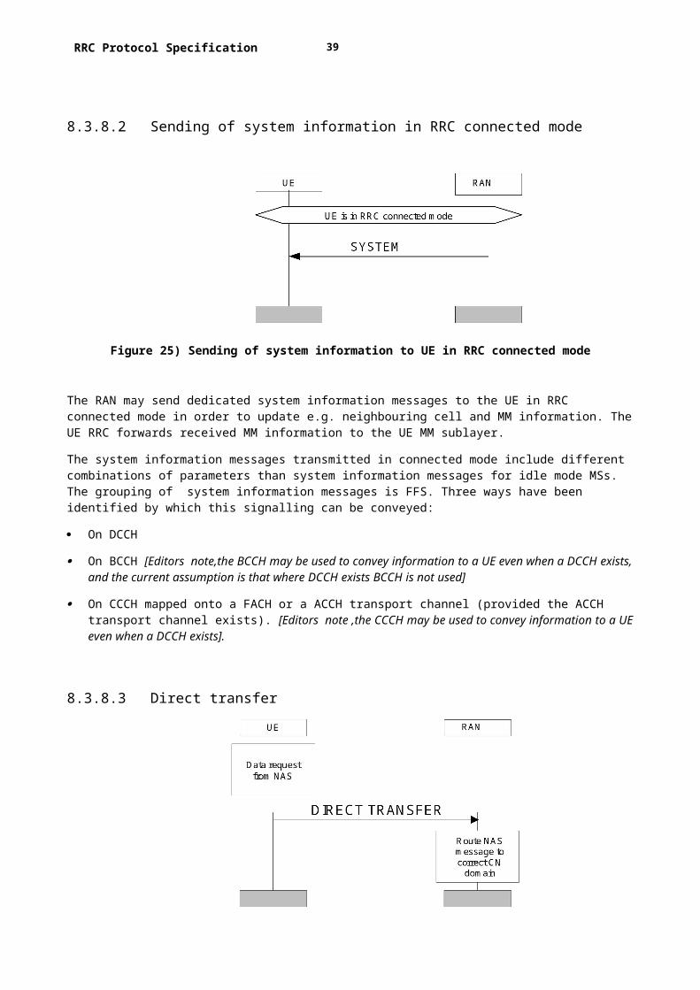
Release any active dedicated physical channels in the uplink and
let the PRACH be the default in the uplink for RACH
9.6.3 Uplink DPCH infoIf the IE “Uplink DPCH info” is included, the UE shall
Release any active uplink physical channels, activate the given physical channels and
enter the CELL_DCH state if not already in that state. Additional actions the UE shall perform when entering the CELL_DCH state from another state are specified in subclause 8.2.1.10.
9.6.4 Downlink DPCH infoIf the IE “Downlink DPCH info” is included, the UE shall
Activate the dedicated physical channels indicated by that IE
9.7 Measurement information elements
9.8 Other information elements
10Message and information element functional definition and content
The function of each Radio Resource Control message together with message contents as a list of Information elements is defined in subclause 10.1.
Functional definitions of the information elements are then described in subclause 10.2.The functions of the Information elements are described in subclause 10.2.
Information elements are marked as either M- mandatory, O - Optional or C -conditional.
(see Table 1).
Abbreviation Meaning
M IE's marked as Mandatory (M) will always be included in the message.
O IE's marked as Optional (O) may or may not be included in the message.
C IE's marked as Conditional (C) will be included in a message only if the condition is satisfied otherwise the IE is not included.
Table 1) meaning of abbreviations used in RRC messages and information elements
39 RRC Protocol Specification

10.1 Radio Resource Control messages
10.1.1 RRC Connection Mobility Messages
10.1.1.1 ACTIVE SET UPDATE
<Functional description of this message to be included here>
RLC-SAP: t.b.d.
Logical channel: DCCH
Direction: RAN UE
Information Element Presence Range IE type and reference
Semantics description
Message Type MUE information elementsActivation time OPhy CH information elementsRadio link addition information 0 to
<MaxAddRLcount>
Radio link addition information required for each RL to add
Primary CCPCH info M Note 1 SSDT cell identity C - ifSSDT Downlink DPCH info MRadio link removal information 0 to
<MaxDelRLcount>
Radio link removal information required for each RL to remove
Primary CCPCH info M Note 1Gated Transmission Control Info O FFS, Note 2SSDT indicator O
Condition Explanation
ifSSDT This IE is only sent when SSDT is being used and a new radio link is added
Range bound Explanation
MaxAddRLcount Maximum number of radio links which can be added
MaxDelRLcount Maximum number of radio links which can be removed/deleted
Note 2: The activation time should be present when the Gated Transmission control info is present in this message.
40 RRC Protocol Specification

10.1.1.2 ACTIVE SET UPDATE COMPLETE
<Functional description of this message to be included here>
RLC-SAP: t.b.d.
Logical channel: DCCH
Direction: UERAN
Information Element Presence Range IE type and reference
Semantics description
Message Type MPhy CH information elementsSSDT indicator O
10.1.1.3 CELL UPDATE
This message is used by the UE to initiate a cell update procedure.
RLC-SAP: t.b.d.
Logical channel: CCCH
Direction: UERAN
Information Element Presence Range IE type and reference
Semantics description
Message Type MUE information elementsSRNC identity MS-RNTI MCell update cause MAM_RLC error indication O Indicates AM_RLC
unrecoverable error occurred on c-plane in the UE
Measurement information elementsMeasurement identity number Intra-frequency measurement
related report Measured results
10.1.1.4 CELL UPDATE CONFIRM
This message confirms the cell update procedure and can be used to reallocate new RNTI information for the UE valid in the new cell.
RLC-SAP: UM
Logical channel: DCCH
41 RRC Protocol Specification
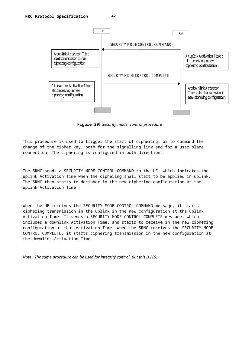
Direction: RANUE
Information Element Presence Range IE type and reference
Semantics description
Message Type MUE information elements
SRNC identity O New SRNC identityS-RNTI O New S-RNTIC-RNTI O New C-RNTIRLC re-configuration indicator C-
AM_RLC_recon
RAN mobility information elementsRRA update indicator ORRA identifier OCN information elementsPLMN identity O (Note1,2)CN related information 0 to
<MaxNoCNdomains>
CN related information to be provided for each CN domain
CN domain identity O (Note1,2) NAS system info O (Note1,2)Physical CH information elements (FFS Note 5)Frequency info O (FFS)Uplink radio resources Uplink DPCH power control info O (FFS) CHOICE channel requirement Uplink DPCH info O (FFS) PRACH info (for RACH) O (FFS) PRACH info (for FAUSCH) O (FFS) Uplink timeslot info O (FFS)Downlink radio resources DL information per radio link 0 to
<maxNoRLs>
Primary CCPCH info O (FFS) Downlink DPCH info O (FFS) Secondary CCPCH info O (FFS) Downlink timeslot info O (FFS) Note 3SSDT indicator O (FFS)CPCH SET Info O (FFS) UL/DL radio resource for CPCH
control (Note4)Gated Transmission Control info O (FFS)Default DPCH Offset Value O (FFS)
CHOICE channel requirement Condition under which the given channel requirement is chosen
Uplink DPCH info
PRACH info (for RACH)
PRACH info (for FAUSCH)
42 RRC Protocol Specification

Range Bound Explanation
maxNoRLs Maximum number of radio links
MaxNoCN domains Maximum number of CN domains
Condition Explanation
AM_RLC_recon This IE is only sent when the RAN requests AM RLC re-configuration
[Note1: It depends on the length of these information whether this message can be used to notify these information to UE.]
[Note2: Necessity of PLMN is FFS and for CN domain identity and NAS system information, the confirmation in SA WG2 is needed.]
Note 3: It is assumed that the DL timeslot configuration is the same for all radio links.
Note 4: How to map UL and DL radio resource in the message is FFS.
Note 5: The inclusion of any physical channel information elements requires further study
10.1.1.5 HANDOVER COMMAND
<Functional description of this message to be included here>
RLC-SAP: t.b.d.
Logical channel: DCCH
Direction: RAN UE
Information Element Presence Range IE type and reference
Semantics description
Message Type MPhy CH information elementsFrequency info MUplink radio resources UL DPCH power control info M UL DPCH info M UL timeslot info ODownlink radio resources Link specific information 1 to
<MaxHoRLcount>
Provide information for each DL radio link. (Note 1)
Primary CCPCH info M DL DPCH info M DL timeslot info O Note 2SSDT indicator OSSDT Cell ID C ifSSDT FFS
43 RRC Protocol Specification
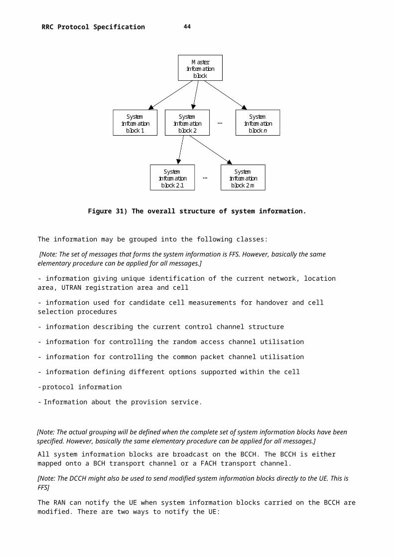
Condition Explanation
ifSSDT This IE is only sent when SSDT is used
Range Bound Explanation
MaxHoRLcount Maximum number of DL radio links which can be established on handover
Note1: The possibility to request the establishment of several radio links simultaneously with this message is FFS.
Note 2: It is assumed that the DL timeslot configuration is the same for all radio links.
10.1.1.6 HANDOVER COMPLETE
<Functional description of this message to be included here>
RLC-SAP: t.b.d.
Logical channel: DCCH
Direction: UE RAN
Information Element Presence Range IE type and reference
Semantics description
Message Type MPhy CH information elementsSSDT indicator O
10.1.1.7 INTER-SYSTEM HANDOVER COMMAND
This message is used for handover from UMTS to another system e.g. GSM. One or several messages from the other system can be included in the Inter-System message information element in this message. These messages are structured and coded according to that systems specification.
RLC-SAP: t.b.d.
Logical channel: DCCH
Direction: RANUE
44 RRC Protocol Specification
Information Element Presence Range IE type and reference
Semantics description
Message Type MUE information elementsActivation time OOther informationelementsInter-System message M
10.1.1.8 INTER-SYSTEM HANDOVER FAILURE
This message is sent on the RRC connection used before the Inter-System Handover was executed. The message indicates that the UE has failed to seize the new channel in the other system.
RLC-SAP: t.b.d.
Logical channel: DCCH
Direction: UERAN
Information Element Presence Range IE type and reference
Semantics description
Message Type MUE information elementsInter-System handover failure cause
O FFS
Other InformationelementsInter-System message O
10.1.1.9 RRA UPDATE
This message is used by the UE to initiate a RRA update procedure.
RLC-SAP: TM
Logical channel: CCCH
Direction: UERAN
Information Element Presence Range IE type and reference
Semantics description
Message Type MUE information elementsSRNC identity MS-RNTI MRRA update cause M
10.1.1.10 RRA UPDATE CONFIRM
45 RRC Protocol Specification
<Functional description of this message to be included here>This message confirms the RRA update procedure and can be used to reallocate new RNTI information for the UE valid after the RRA update.
RLC-SAP:UM
Logical channel: CCCH or DCCH
Direction: RANUE
Information Element Presence Range IE type and reference
Semantics description
Message Type MUE information elementsSRNC identity C-CCCHS-RNTI C-CCCHSRNC identity O New SRNC identityS-RNTI O New S-RNTIC-RNTI O New C-RNTIRAN mobility information elementsRRA identifier OCN information elementsPLMN identity O (Note1,2)CN related information 0 to
<MaxNoCNdomains>
CN related information to be provided for each CN domain
CN domain identity O (Note1,2) NAS system info O (Note1,2)
Range Bound Explanation
MaxNoCN domains Maximum number of CN domains
Condition Explanation
CCCH This IE is only sent when CCCH is used
[Note1: It depends on the length of these information whether this message can be used to notify these information to UE.]
[Note2: Necessity of PLMN is FFS and for CN domain identity and NAS system information are ffs]
10.1.1.11 RNTI REALLOCATION
<Functional description of this message to be included here>
46 RRC Protocol Specification

RLC-SAP: AM or UM
Logical channel:DCCH
Direction: RANUE
Information Element Presence Range IE type and reference
Semantics description
Message Type MUE information elements
S-RNTI O New S-RNTISRNC identity O New SRNC identityC-RNTI O New C-RNTICN information elementsPLMN identity O (Note1,2)CN related information 0 to
<MaxNoCNdomains>
CN related information to be provided for each CN domain
CN domain identity O (Note1,2) NAS system info O (Note1,2)
Range Bound Explanation
MaxNoCN domains Maximum number of CN domains
[Note1: It depends on the length of these information whether this message can be used to notify these information to UE.]
[Note2: Necessity of PLMN is FFS and for CN domain identity and NAS system information are ffs]
10.1.1.12 RNTI REALLOCATION COMPLETE
This message is used to confirm the new RNTI information for the UE.
RLC-SAP: AM
Logical channel: DCCH
Direction: UERAN
47 RRC Protocol Specification

Information Element Presence Range IE type and reference
Semantics description
Message Type M
10.1.2 Measurement Messages
10.1.2.1 MEASUREMENT CONTROL
<Functional description of this message to be included here>
RLC-SAP: AM.
Logical channel: DCCH
Direction: RANUE
48 RRC Protocol Specification
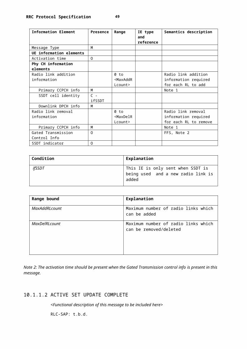
Information Element Presence Range IE type and reference
Semantics description
Message Type MMeasurement Information elementsMeasurement Identity Number MMeasurement Command MMeasurement Type OMeasurement Reporting Mode OCHOICE Measurement Intra-frequency Intra-frequency cell info Measurement object Intra-frequency measurement quantity
C event trigger
Intra-frequency measurement reporting quantity
O Note 1
CHOICE report criteria Intra-frequency measurement reporting criteria Periodical reporting Inter-frequency Inter-frequency cell info Measurement object Inter-frequency measurement quantity
C event trigger
Inter-frequency measurement reporting quantity
O Note 1
CHOICE report criteria Inter-frequency measurement reporting criteria Periodical reporting Inter-system Inter-system cell info Measurement object Inter-system measurement quantity
C event trigger
Inter-system measurement reporting quantity
O Note 1
CHOICE report criteria Inter-system measurement reporting criteria Periodical reporting Traffic Volume Traffic volume measurement Object Traffic volume measurement quantity
C event trigger
Traffic volume measurement reporting quantity
O Note 1
CHOICE report criteria Traffic volume measurement reporting criteria Periodical reporting Quality Quality measurement Object Quality measurement quantity
C event trigger
Quality measurement reporting quantity
O Note 1
CHOICE report criteria Quality measurement reporting criteria Periodical reporting UE internal
49 RRC Protocol Specification
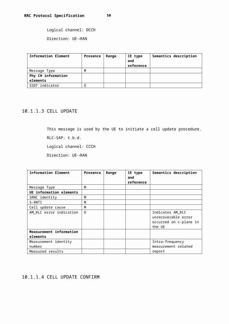
UE internal measurement quantity
C event trigger
UE internal measurement reporting quantity
O Note 1
CHOICE report criteria UE internal measurement reporting criteria Periodical reporting
Condition Explanation
event trigger This element is only included in the message which is sent in event trigger reporting mode.
CHOICE Measurement Condition under which the given Measurement is chosen
intra-frequency if measurement type=Intra-frequency measurement
inter-frequency if measurement type=Inter-frequency measurement
inter-system if measurement type=Intra-system measurement
traffic volume if measurement type=traffic volume measurement
Quality if measurement type=Quality measurement
UE internal if measurement type=UE internal measurement
CHOICE reporting criteria Condition under which the given reporting criteria is chosen
******* measurement reporting criteria Chosen when event triggering is required
periodical reporting Chosen when periodical reporting is required
Note 1: It is FFS whether it is necessary to separate the reporting quantity for each type.
Note 2: The network may order the UE to report other measurements when UE internal measurements are reported
10.1.2.2 MEASUREMENT REPORT
<Functional description of this message to be included here>
RLC-SAP: AM or UM, as configured by RAN within measurement control
Logical channel: DCCH
Direction: UERAN
50 RRC Protocol Specification
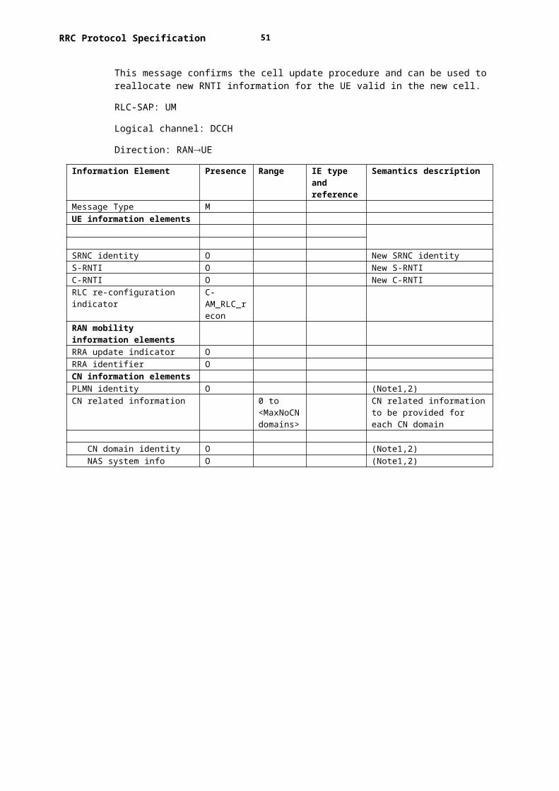
Information Element Presence Range IE type and reference
Semantics description
Message Type MMeasurement Information ElementsMeasurement report information 1 to
<maxMeasRepCount>
Send Measurement Report information for each measurement report in the message (Note 1)
Measurement identity number M Measured Results C MR
required CHOICE event result C event
triggerNote 1,2
Intra-frequency measurement event results Inter-frequency measurement event results Inter-system measurement event results Traffic volume measurement event results Quality measurement event results
Condition Explanation
event trigger This element is only included in the message which is sent in event trigger reporting mode.
MR required This information element is included by the sender only if indicated optionally by Reporting Quantity in Measurement Control
Range Bound Explanation
MaxMeasRepCount Maximum number of Measurement reports in a message
CHOICE event result Condition under which the given event result is chosen
intra-frequency measurement event results
inter-frequency measurement event results
inter-system measurement event results
traffic volume measurement event results
Quality measurement event results
Note 1: Whether it is possible to send multiple measurement results that are identified by different measurement
51 RRC Protocol Specification
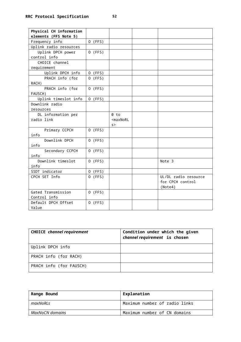
identity numbers in the same Measurement Report is FFS. An alternative solution is to allowt only one measurement identity number per Measurement Report and concatenate different Measurement Reports in the RLC layer instead.
Note 2: If it is possible to send many measurement results that are identified by different events in the same Measurement Report is FFS..
10.1.3 Paging and Notification Messages
10.1.3.1 NOTIFICATION
<Functional description of this message to be included here>
RLC-SAP:TM
Logical channel: PCCH
Direction: RAN UE
Information Element Presence Range IE type and reference
Semantics description
Message Type M
10.1.3.2 PAGING TYPE 1
This message is used to send information on the paging channel. One or several UEs, in idle or connected mode,can be paged in one message, which also can contain other information.
RLC-SAP: TM
Logical channel: PCCH
Direction: RAN UE
Information Element Presence Range IE type and reference
Semantics description
Message Type MUE Information elementsPaging record 1 to <Page
Count>
Other information elementsBCCH modification info O FFS
Range Bound Explanation
Page Count Number of UE's paged in the Paging Type 1 message
10.1.3.3 PAGING TYPE 2
This message is used to page an UE in connected mode, when using the DCCH for CN originated paging.
52 RRC Protocol Specification
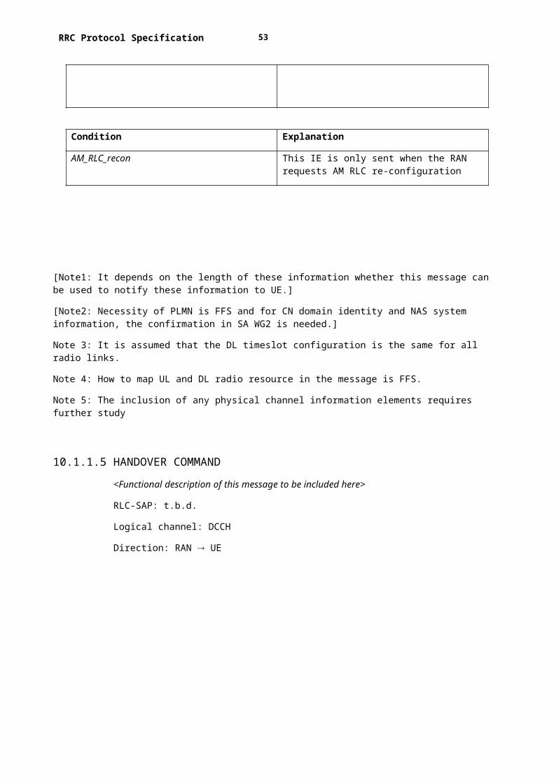
RLC-SAP: AM
Logical channel: DCCH
Direction: RAN UE
Information Element Presence Range IE type and reference
Semantics description
Message Type MCN Information elementsCN domain identity MUE Information elements
Paging cause M
10.1.4 RRC Connection Establishment and maintenance messages
10.1.4.1 RRC CONNECTION RE-ESTABLISHMENT
<Functional description of this message to be included here>
RLC-SAP: UM
Logical channel:DCCH
Direction: RAN UE
Information Element Presence Range IE type and reference
Semantics description
Message Type MPhysical CH information elements (FFS Note 3)Frequency info O (FFS)Uplink radio resources Uplink DPCH power control info O (FFS) CHOICE channel requirement Uplink DPCH info O (FFS) PRACH info (for RACH) O (FFS) PRACH info (for FAUSCH) O (FFS) Uplink timeslot info O (FFS)Downlink radio resources DL information per radio link 0 to
<maxNoRLs>
Primary CCPCH info O (FFS) Downlink DPCH info O (FFS) Secondary CCPCH info O (FFS) Downlink timeslot info O (FFS) Note 1SSDT indicator O (FFS)CPCH SET Info O (FFS) UL/DL radio resource for CPCH
control (Note 2)Default DPCH Offset Value O (FFS)
53 RRC Protocol Specification
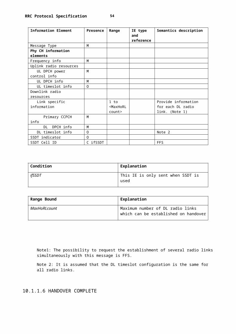
CHOICE channel requirement Condition under which the given channel requirement is chosen
Uplink DPCH info
PRACH info (for RACH)
PRACH info (for FAUSCH)
Range Bound Explanation
maxNoRLs Maximum number of radio links
Note 1: It is assumed that the DL timeslot configuration is the same for all radio links.
Note 2: How to map UL and DL radio resource in the message is FFS.
Note 3: All parameters in this message are FFS
10.1.4.2 RRC CONNECTION RE-ESTABLISHMENT COMPLETE
<Functional description of this message to be included here>
RLC-SAP:AM
Logical channel: DCCH
Direction: UE RAN
Information Element Presence Range IE type and reference
Semantics description
Message Type M
10.1.4.3 RRC CONNECTION RE-ESTABLISHMENT REQUEST
<Functional description of this message to be included here>
RLC-SAP: TM
Logical channel: CCCH
Direction: UE RAN
54 RRC Protocol Specification
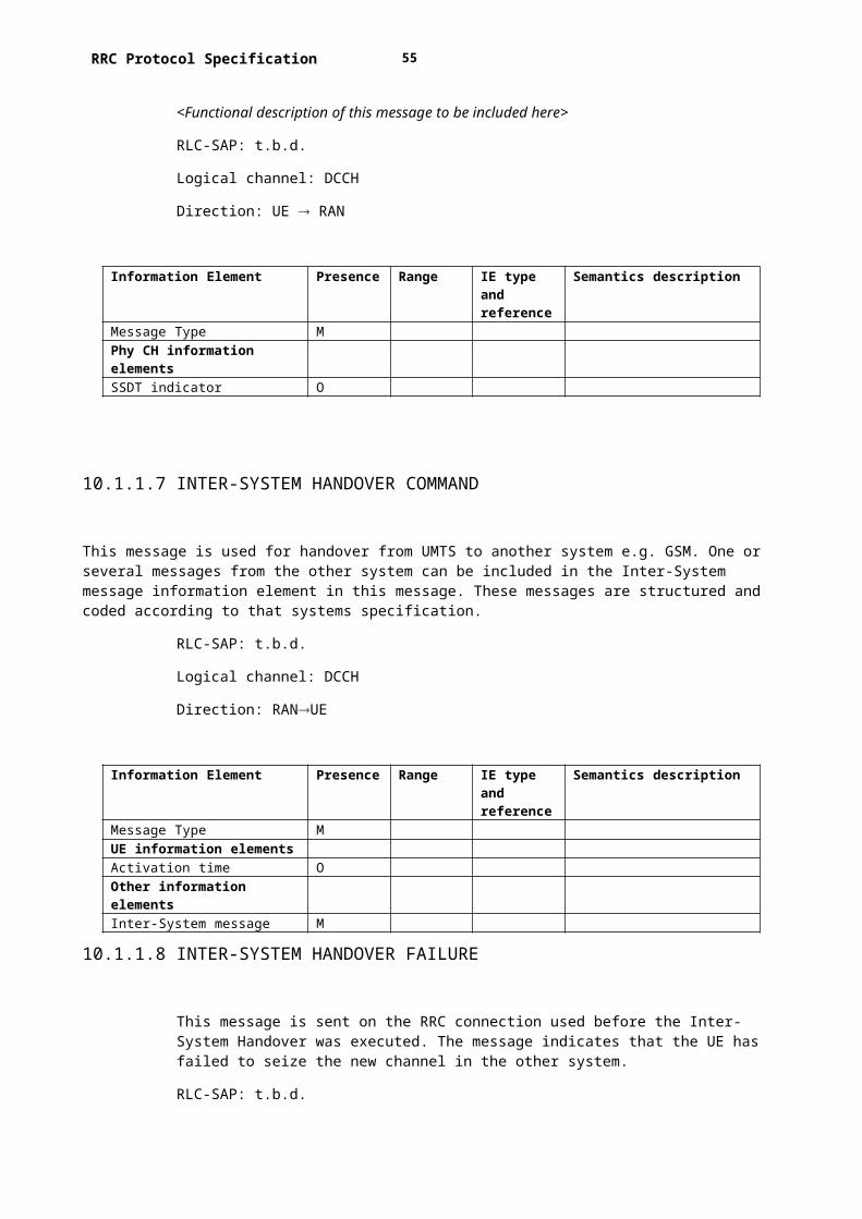
Information Element Presence Range IE type and reference
Semantics description
Message Type MUE information elementsSRNC identity MS-RNTI MMeasurement information elementsMeasurement information 1 to
<MeasRepCount>
Send Measurement information for each measurement report in the message
Measurement identity number M Refers to system information. Note 1
Measured results M
Note 1: The necessity and usage of Measurement identity number in this message is FFS.
Range Bound Explanation
MeasRepCount Number of measurement reports in the message
10.1.4.4 RRC CONNECTION RELEASE
<Functional description of this message to be included here>
RLC-SAP: UM
Logical channel: DCCH
Direction: RANUE
Information Element Presence Range IE type and reference
Semantics description
Message Type MUE information elementsRelease cause MNumber of Quick Repeat M
10.1.4.5 RRC CONNECTION RELEASE COMPLETE
<Functional description of this message to be included here>
RLC-SAP: AM in case of release without dedicated channel and UM in case of release with dedicated channel
Logical channel: DCCH
Direction: UE RAN
55 RRC Protocol Specification

Information Element Presence Range IE type and reference
Semantics description
Message Type M
10.1.4.6 RRC CONNECTION REQUEST
RRC Connection Request is the first message transmitted by the UE when setting up an RRC Connection to the network.
RLC-SAP: TM
Logical channel: CCCH
Direction: UE RAN
Information Element Presence Range IE type and reference
Semantics description
Message Type MUE information elementsInitial UE identity MEstablishment cause MInitial UE capability O Necessity is FFSMeasurement information elementsMeasurement information 1 to
<MeasRepCount>
Send Measurement information for each measurement report in the message
Measurement identity number M Refers to system information. Note 1
Measured results MNote 1: The necessity and usage of Measurement identity number in this message is FFS.
Range Bound Explanation
MeasRepCoun Number of measurement reports in the message
10.1.4.7 RRC CONNECTION SETUP
This message is used by the network to accept the establishment of an RRC connection for an UE, including assignment of signalling link information, transport channel information and optionally physical channel information.
RLC-SAP: UM
Logical channel: CCCH
56 RRC Protocol Specification
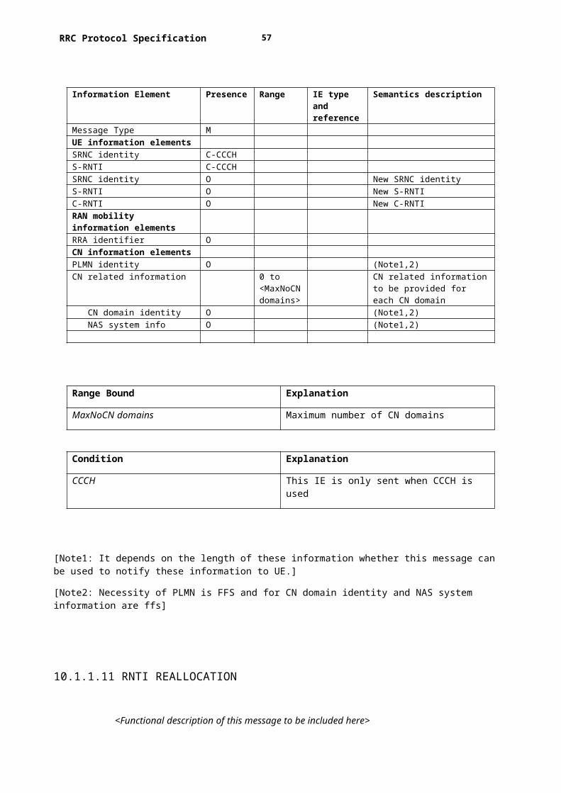
Direction: RAN UE
Information Element Presence Range IE type and reference
Semantics description
Message Type MUE information elementsInitial UE identity MS-RNTI MSRNC identity MC-RNTI O Only if assigned to a common
transport channelActivation time ORB information elementsRB identity M Indicates the signalling linkSignalling link type MRB multiplexing info M For the signalling linkTrCH information elementsTFCS O Uplink TFCSTFCS O Downlink TFCSTFC subset OUplink transport channel information
0 to <MaxULTrCHCount>
Send transport channel information for each new Uplink transport channel
Transport channel identity M TFS MDownlink transport channel information
0 to <MaxDLTrCHCount>
Send transport channel information for each new downlink transport channel
Transport channel identity M TFS MPhyCH information elementsFrequency info OUplink DPCH power control info OUplink radio resource information Uplink timeslot info O CHOICE channel requirement
O
Uplink DPCH info PRACH info (for RACH)Downlink radio resource information Downlink DPCH power control info
O
Downlink DPCH compressed mode info
O
Downlink information 0 to <Max RLcount>
Send downlink information for each radio link to be set-up
Primary CCPCH info Downlink DPCH info Secondary CCPCH info Downlink timeslot info O Note 1SSDT indicator O FFSSSDT Cell ID C ifSSDT FFSCPCH SET Info O UL/DL radio resource for CPCH
control (Note2)Gated Transmission Control info O, FFS Note 3Default DPCH Offset Value O
57 RRC Protocol Specification
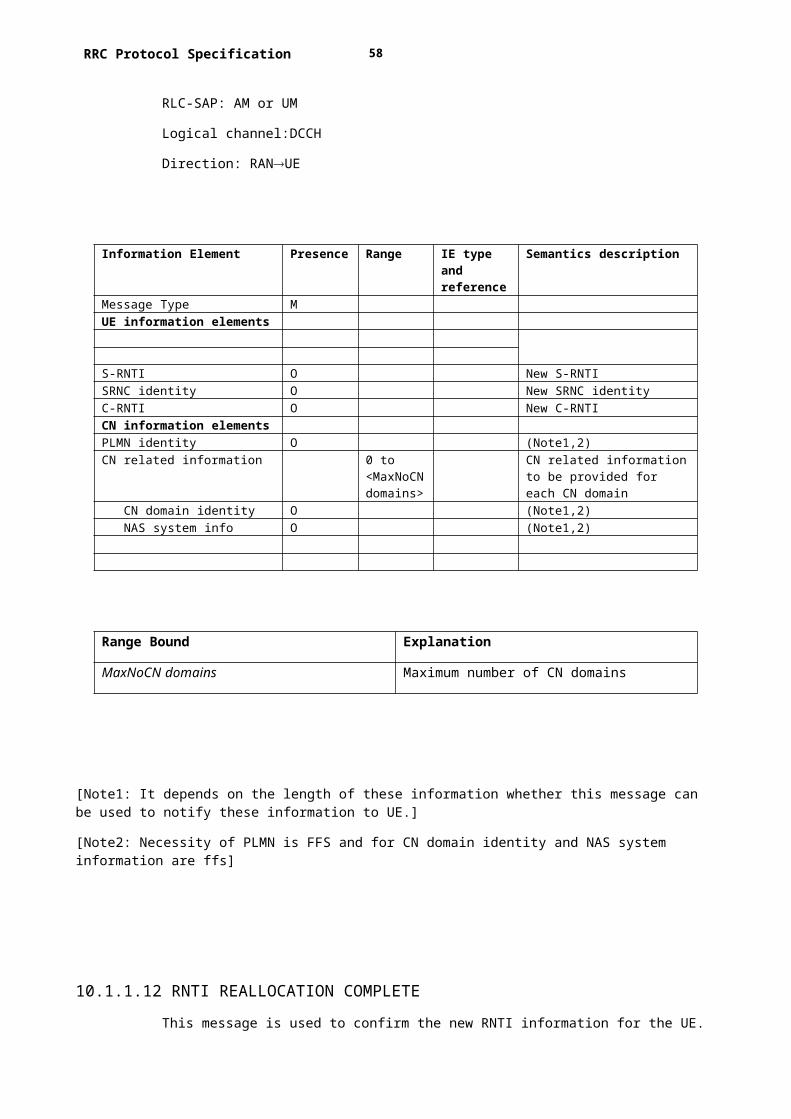
Condition Explanation
ifSSDT This IE is sent only when SSDT is to be used
Range Bound Explanation
MaxULTrCHCoun Maximum number of new uplink transport channels
MaxDLTrCHCount Maximum number of new downlink transport channels
MaxRLcoun Maximum number of radio links to be set up
CHOICE channel requirement Condition under which the given channel requirement is chosen
Uplink DPCH info
PRACH info
Note 1: It is assumed that the DL timeslot configuration is the same for all radio links.
Note 2: How to map UL and DL radio resource in the message is FFS.
Note 3: The activation time should be present when the Gated Transmission control info is present in this message.
10.1.4.8 RRC CONNECTION SETUP COMPLETE
This message confirms the establishment of the RRC Connection by the UE.
RLC-SAP: t.b.d.
Logical channel: DCCH
Direction: UE RAN
Information Element Presence Range IE type and reference
Semantics description
Message Type MPhy CH information elementsSSDT indicator O FFS
10.1.4.9 RRC CONNECTION REJECT
This message is transmitted by the network when the requested RRC connection cannot be accepted.
RLC-SAP: AM
Logical channel: CCCH
Direction: RAN UE
58 RRC Protocol Specification
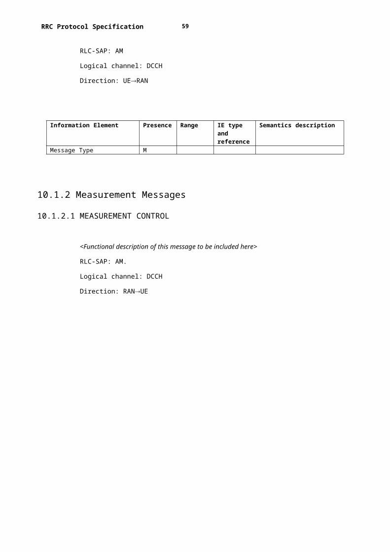
Information Element Presence Range IE type and reference
Semantics description
Message Type MUE information elementsInitial UE identity MRejection cause MWait time O
10.1.4.10 RRC STATUS
This message is transmitted by the network when the network requests UE to release one of several signalling connections.
RLC-SAP: UM
Logical channel: DCCH
Direction: RAN UE
Information Element Presence Range IE type and reference
Semantics description
Message Type MCN information elementsCN domain identity M
10.1.4.11 RRC STATUS ACK
This message is transmitted by UE as an acknowledgement for RRC STATUS message.
RLC-SAP: UM
Logical channel: DCCH
Direction: UE RAN
Information Element Presence Range IE type and reference
Semantics description
Message Type M
59 RRC Protocol Specification

10.1.5 Radio Bearer control messages
10.1.5.1 PHYSICAL CHANNEL RECONFIGURATION
This message is used by RAN to assign, replace or release a set of physical channels used by a UE.
RLC-SAP: AM or UM
Logical channel: DCCH
Direction: RAN UE
Information Element Presence Range IE type and reference
Semantics description
Message Type MUE Information elementsActivation time OC-RNTI C -
RACH/FACH
RAN mobility Information elementsRRA update indicator C - PCH
and optional
Physical Channel information elementsFrequency info OUplink DPCH power control info OUplink radio resource information CHOICE channel requirement
O
Uplink DPCH info PRACH Info (for RACH) PRACH info (for FAUSCH) Uplink timeslot info ODownlink radio resource information Downlink DPCH power control info
O
Downlink DPCH compressed mode info
O
Downlink information 0 to <Max RLcount>
Send downlink information for each radio link
Primary CCPCH info Downlink DPCH info Secondary CCPCH info For FACH Secondary CCPCH info For PCH Downlink timeslot info O Note 1SSDT indicator O FFSSSDT Cell ID C ifSSDT FFSCPCH SET Info O UL/DL radio resource for CPCH
control (Note2)
Default DPCH Offset Value O
Condition Explanation
60 RRC Protocol Specification
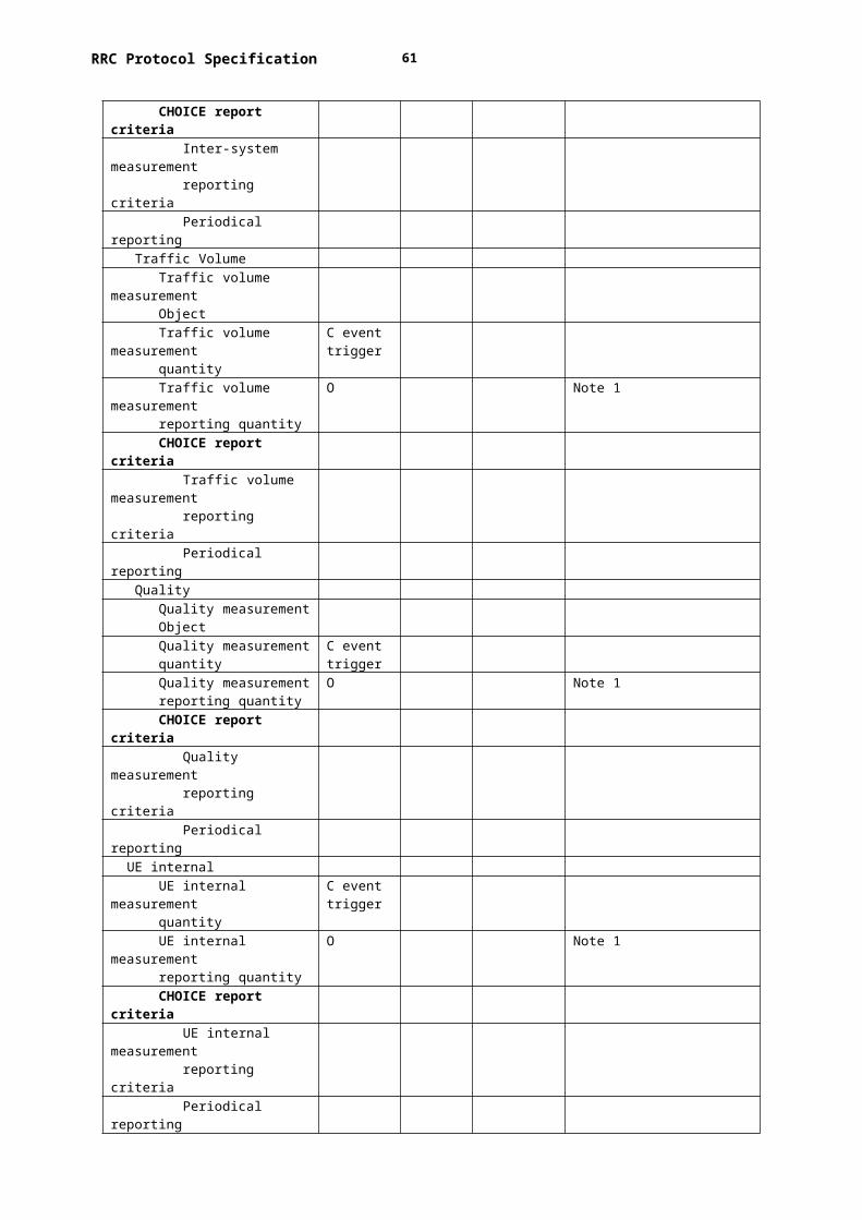
ifSSDT This IE is only sent when SSDT is used and when a new DCH is being activated
RACH/FACH This information element is only included in the sent message when using RACH/FACH
PCH This information element is only included in the sent message when PCH is being used and is optional even then.
Range Bound Explanation
MaxRLcount Maximum number of radio links to be set up
CHOICE channel requirement Condition under which the given channel requirement is chosen
Uplink DPCH info
PRACH info (for FAUSCH)
PRACH info (for RACH)
Note 1: It is assumed that the DL timeslot configuration is the same for all radio links.
Note 2: How to map UL and DL radio resource in the message is FFS.
10.1.5.2 PHYSICAL CHANNEL RECONFIGURATION COMPLETE
This message is sent from the UE when a physical channel reconfiguration has been done.
RLC-SAP: AM
Logical channel: DCCH
Direction: UE RAN
Information Element Presence Range IE type and reference
Semantics description
Message Type MPhy CH information elementsSSDT indicator O Necessity is FFS
10.1.5.3 RADIO BEARER RECONFIGURATION
61 RRC Protocol Specification

This message is sent from RAN to reconfigure parameters related to a change of QoS. This procedure can also change the multiplexing of MAC, reconfigure transport channels and physical channels.
RLC-SAP: AM or UM
Logical channel: DCCH
Direction: RAN UE
62 RRC Protocol Specification

Information Element Presence Range IE type and reference
Semantics description
Message Type MUE Information elementsActivation time OC-RNTI C -
RACH/FACH
RB information elements RB information 0 to
<MaxRBcount>
RB information is sent for each RB affected by this message
RB identity M RLC info O FFS RB multiplexing info MTransport Channel Information ElementsTFCS O for uplink DCHsTFCS O for downlink DCHsTFC subset O for DCHs in uplinkUplink transport channels Transport channel identity 0 to
<MaxDelTrCH>
Reconfigured TrCH information
0 to <MaxReconAddTrCH>
Transport channel identity M TFS M DRAC information C DRAC 1 to
<MaxReconAddTrCH>
Dynamic Control Transmission time validity Time duration before retry Silent period duration before releaseDownlink transport channels Transport channel identity 0 to
<MaxDelTrCH>
Reconfigured TrCH information
0 to <MaxReconAddTrCH>
Transport channel identity M TFS MPhysical Channel information elementsFrequency info OUplink DPCH power control info
O
Uplink radio resource information
O
CHOICE channel requirement
O
Uplink DPCH info PRACH info (for RACH) PRACH info (for FAUSCH) Uplink timeslot info ODownlink radio resource information Downlink DPCH power control info
O
63 RRC Protocol Specification
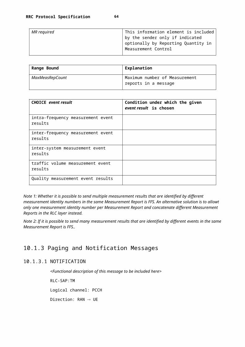
Downlink DPCH compressed mode info
O
Downlink information 0 to <Max RLcount>
Send downlink information for each radio link
Primary CCPCH info Downlink DPCH info Secondary CCPCH info Downlink timeslot info O Note 1SSDT indicator O FFSCPCH SET Info O UL/DL radio resource for CPCH
control (Note2)Gated Transmission Controlinfo
O FFS, Note 3
Default DPCH Offset Value O
Condition Explanation
RACH/FACH This information element is only sent when using RACH/FACH
DRAC These information elements are only sent for transport channels which use the DRAC procedure
Range Bound Explanation
MaxRLcount Maximum number of radio links
MaxRBcount Maximum number of RBs to be reconfigured
MaxDelTrCHcount Maximum number of Transport CHannels to be removed
MaxReconAddTrCH Maximum number of transport channels to add and reconfigure
CHOICE channel requirement Condition under which the given channel requirement is chosen
Uplink DPCH info
PRACH info (for RACH)
Note 1: It is assumed that the DL timeslot configuration is the same for all radio links.
Note 2: How to map UL and DL radio resource in the message is FFS.
Note 3: The activation time should be present when the Gated Transmission control info is present in this message.
64 RRC Protocol Specification

10.1.5.4 RADIO ACCESS BEARER RECONFIGURATION COMPLETE
This message is sent from the UE when a RAB and signalling link reconfiguration has been done.
RLC-SAP:AM
Logical channel: DCCH
Direction: UE RAN
Information Element Presence Range IE type and reference
Semantics description
Message Type MPhy CH information elementsSSDT indicator O FFS
10.1.5.5 RADIO BEARER RELEASE
<Functional description of this message to be included here>
RLC-SAP: AM or UM
Logical channel: DCCH
Direction: RAN UE
65 RRC Protocol Specification
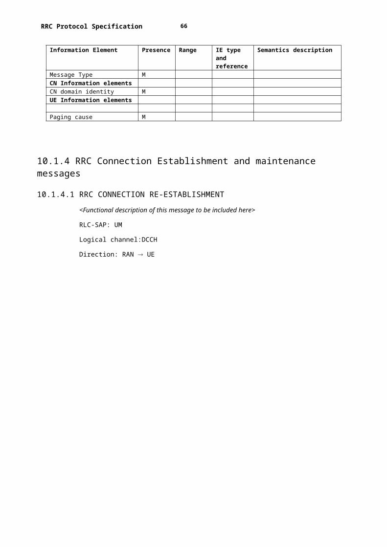
Information Element Presence Range IE type and reference
Semantics description
Message Type MUE Information elementsActivation time OC-RNTI C -
RACH/FACH
RB information elementsRB identity 1 to
<MaxRelRBcount>
RB identity 0 to <MaxOtherRBcount>
RB multiplexing info OTransport Channel Information ElementsTFCS O for uplink DCHsTFCS O for downlink DCHsTFC subset O for DCHs in uplinkUplink transport channels Transport channel identity 0 to
<MaxDelTrCH>
Reconfigured TrCH information
0 to <MaxReconAddFFSTrCH>
Transport channel identity M TFS M DRAC information C DRAC 1 to
<MaxReconAddFFSTrCH>
Dynamic Control Transmission time validity Time duration before retry Silent period duration before releaseDownlink transport channels Transport channel identity 0 to
<MaxDelTrCH>
Reconfigured TrCH information
0 to <MaxReconAddTrCH>
Editor : this limit should probably also be MaxReconAddFFSTrCH
Transport channel identity M TFS MPhysical Channel information elementsFrequency info OUplink DPCH power control info
O
Uplink radio resource information
O
Gated Transmission Control info O, FFS Note 3CPCH SET Info O UL/DL radio resource for CPCH
control (Note2) CHOICE channel requirement
O
Uplink DPCH info PRACH info (for FAUSCH) PRACH info (for RACH) Uplink timeslot info O
66 RRC Protocol Specification

Downlink radio resource information Downlink information 0 to <Max
RLcount>Send downlink information for each radio link to be set-up
Primary CCPCH info Downlink DPCH info Secondary CCPCH info Downlink timeslot info O Note 1
Condition Explanation
RACH/FACH This information element is only sent when using RACH/FACH
DRAC These information elements are only sent for transport channels which use the DRAC procedure
Range Bound Explanation
MaxRLcount Maximum number of radio links
MaxDelRBcount Maximum number of RBs to be released/deleted
MaxOtherRBcount Maximum number of Other RBs (ie RB's not being released) affected by the procedure
MaxDelTrCHcount Maximum number of Transport CHannels to be removed
MaxReconAddFFSTrCH Maximum number of transport channels to add (FFS) and reconfigure
CHOICE channel requirement Condition under which the given channel requirement is chosen
Uplink DPCH info
PRACH Info (for RACH)
Note 1: It is assumed that the DL timeslot configuration is the same for all radio links.
Note 2: How to map UL and DL radio resource in the message is FFS.
Note 3: The activation time should be present when the Gated Transmission control info is present in this message.
67 RRC Protocol Specification
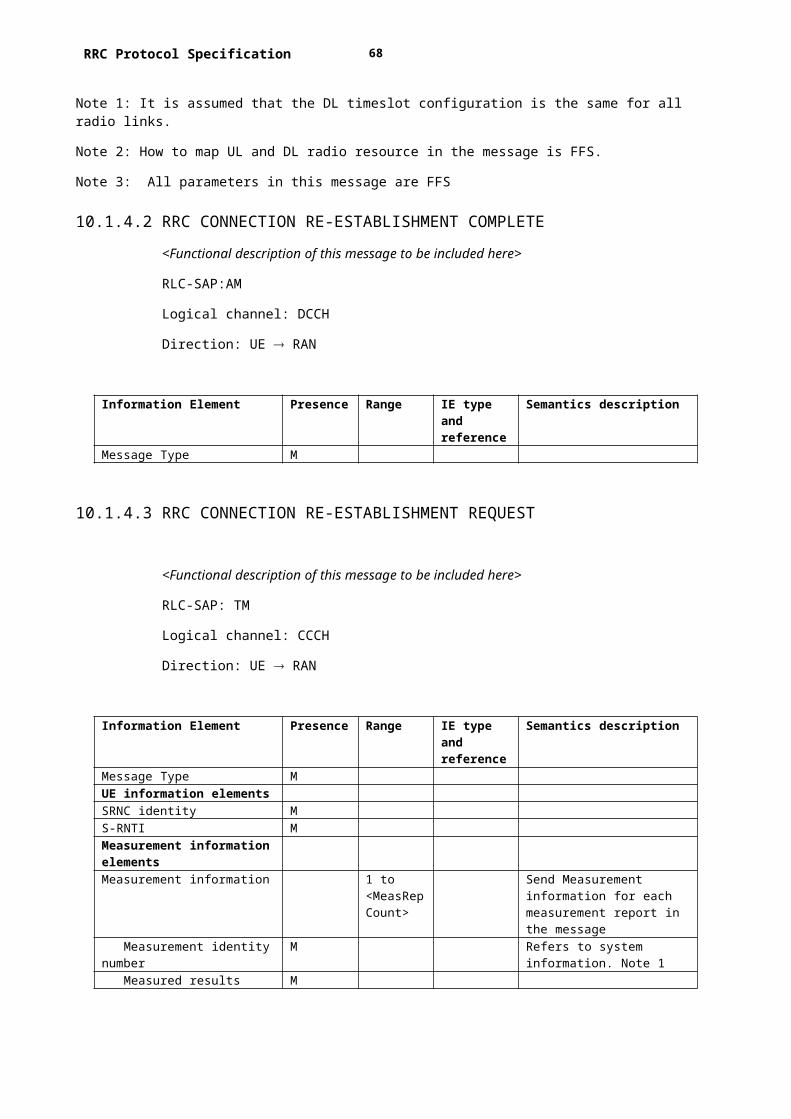
10.1.5.6 RADIO ACCESS BEARER RELEASE COMPLETE
<Functional description of this message to be included here>
RLC-SAP: AM
Logical channel: DCCH
Direction: UE RAN
Information Element Presence Range IE type and reference
Semantics description
Message Type M
10.1.5.7 RADIO BEARER SETUP
<Functional description of this message to be included here>
RLC-SAP:AM or UM
Logical channel: DCCH
Direction: RAN UE
68 RRC Protocol Specification
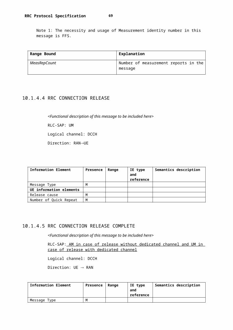
Information Element Presence Range IE type and reference
Semantics description
Message Type MCN information elementsNAS binding info MCN domain identityUE Information elementsActivation time OC-RNTI C -
RACH/FACH
RB information elementsRB identity M For the new RBRLC info MRB multiplexing info MInformation for other RB's affected by this message
0 to <MaxOtherRBcount>
RB identity M RB multiplexing info MTransport Channel Information ElementsTFCS O for uplink DCHsTFCS O for downlink DCHsTFC subset O for DCHs in uplinkUplink transport channels Transport channel identity 0 to
<MaxDelTrCH>
editor should this be FFS also?
Reconfigured TrCH information
0 to <MaxReconAddTrCH>
Transport channel identity M TFS M DRAC information C DRAC 1 to
<MaxReconAddTrCH>
Dynamic Control Transmission time validity Time duration before retry Silent period duration before releaseDownlink transport channels Transport channel identity 0 to
<MaxDelTrCH>
FFS
Reconfigured TrCH information
0 to <MaxReconAddTrCH>
Transport channel identity M TFS MPhysical Channel information elementsFrequency info OUplink DPCH power control info
O
Uplink radio resource information
O
CPCH SET Info O UL/DL radio resource for CPCH control (Note2)
CHOICE channel requirement
O
Uplink DPCH info
69 RRC Protocol Specification
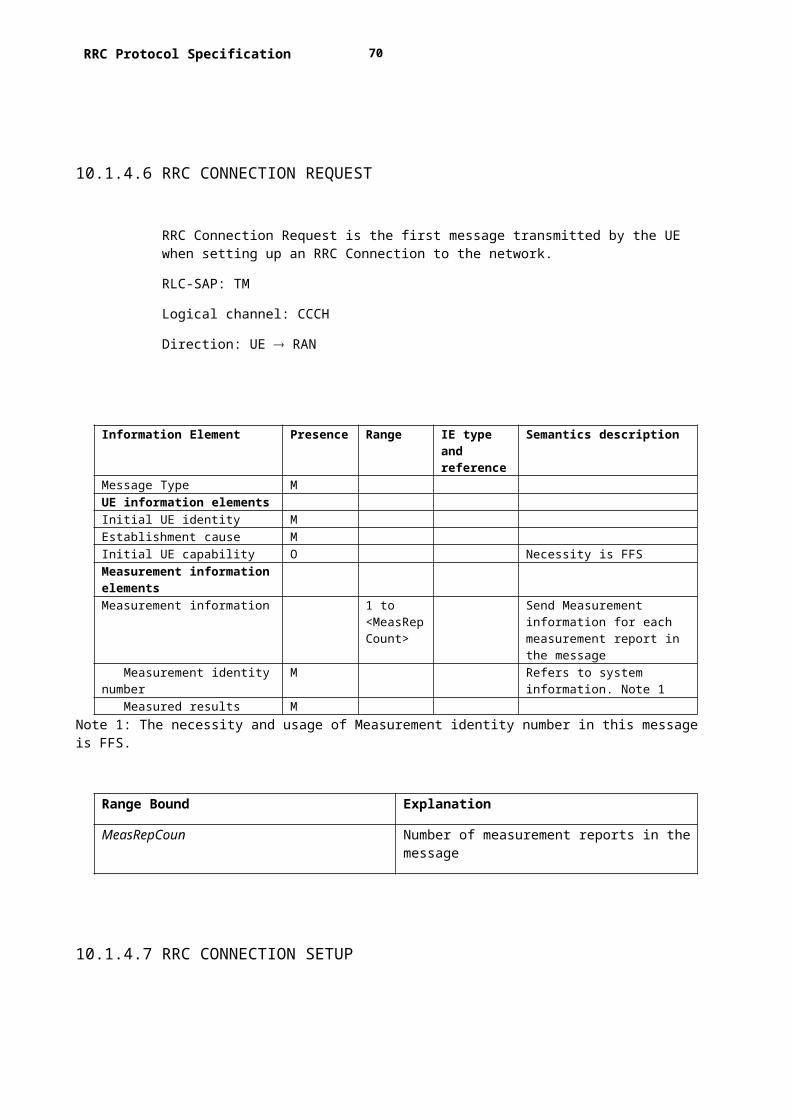
PRACH Info (for RACH) PRACH info (for FAUSCH) Uplink timeslot info ODownlink radio resource information Downlink DPCH power control info
O
Downlink DPCH compressed mode info
O
Downlink information 0 to <Max RLcount>
Send downlink information for each radio link
Primary CCPCH info Downlink DPCH info Secondary CCPCH info Downlink timeslot info O Note 1SSDT indicator O FFSSSDT Cell ID C ifSSDT FFSGated Transmission Controlinfo
O FFS
Default DPCH Offset Value O
Condition Explanation
RACH/FACH This information element is only sent when using RACH/FACH
IfSSDT This IE is only sent when SSDT is used and when a new DCH is being activated
Range Bound Explanation
MaxRLcount Maximum number of radio links
MaxDelTrCHcount Maximum number of Transport CHannels to be removed
MaxReconAddcount Maximum number of Transport CHannels reconfigured or added
MaxOtherRBcount Maximum number of Other RBs (ie RB's not being released) affected by the procedure
CHOICE channel requirement Condition under which the given channel requirement is chosen
Uplink DPCH info
PRACH info (for FAUSCH)
PRACH info (for RACH)
Note 1: It is assumed that the DL timeslot configuration is the same for all radio links.
70 RRC Protocol Specification

Note 2: How to map UL and DL radio resource in the message is FFS.
Note 3: The activation time should be present when the Gated Transmission control info is present in this message.
10.1.5.8 RADIO ACCESS BEARER SETUP COMPLETE
<Functional description of this message to be included here>
RLC-SAP: AM
Logical channel: DCCH
Direction: UE RAN
Information Element Presence Range IE type and reference
Semantics description
Message Type MPhy CH information elementsSSDT indicator O FFS
10.1.5.9 TRANSPORT CHANNEL RECONFIGURATION
This message is used by RAN to configure the transport channel of a UE. This also includes a possible reconfiguration of physical channels. The message can also be used to assign a TFC subset and reconfigure physical channel.
RLC-SAP: AM or UM
Logical channel: DCCH
Direction: RAN UE
71 RRC Protocol Specification

Information Element Presence Range IE type and reference
Semantics description
Message Type MUE Information elementsActivation time OC-RNTI C -
RACH/FACH
Control only state timer O FFSTransport Channel Information ElementsTFCS O For uplink DCHsTFCS O For downlink DCHsTFC subset O For DCHs in uplinkUplink transport channels Reconfigured TrCH information
0 to <MaxReconTrCH>
Transport channel identity TFS DRAC information C DRAC 1 to
<MaxReconTrCHDRAC>
Dynamic Control Transmission time validity Time duration before retry Silent period duration before releaseDownlink transport channels Reconfigured TrCH information
0 to <MaxReconTrCH>
Transport channel identity TFSPhysical Channel information elementsFrequency info OUplink DPCH power control info
O
Uplink radio resource informationCPCH SET Info O UL/DL radio resource for CPCH
control (Note2) CHOICE channel requirement
O
Uplink DPCH info PRACH info (for RACH) Uplink timeslot info ODownlink radio resource information Downlink DPCH power control info
O
Downlink DPCH compressed mode info
O
Downlink information 0 to <Max RLcount>
Send downlink information for each radio link
Primary CCPCH info Downlink DPCH info Secondary CCPCH info Downlink timeslot info O Note 1SSDT indicator O FFSSSDT Cell ID C ifSSDT FFSGated Transmission Controlinfo
O FFS, Note 3
72 RRC Protocol Specification

Default DPCH Offset Value O
Condition Explanation
ifSSDT This IE is only sent when SSDT is used and when a new DCH is being activated
RACH/FACH This information element is only sent when using RACH/FACH
Range Bound Explanation
MaxRLcount Maximum number of radio links to be set up
MaxReconcount Maximum number of Transport CHannels reconfigured
MaxReconTrCHDRAC Maximum number of Transport CHannels which are controlled by DRAC and which are reconfigured
CHOICE channel requirement Condition under which the given channel requirement is chosen
Uplink DPCH info
PRACH info (for RACH)
Note 1: It is assumed that the DL timeslot configuration is the same for all radio links .
Note 2: How to map UL and DL radio resource in the message is FFS.
Note 3: The activation time should be present when the Gated Transmission control info is present in this message.
10.1.5.10 TRANSPORT CHANNEL RECONFIGURATION COMPLETE
This message is sent from the UE when a transport channel reconfiguration has been done.
RLC-SAP: AM
Logical channel: DCCH
Direction: UE RAN
Information Element Presence Range IE type and reference
Semantics description
Message Type MPhy CH information elementsSSDT indicator O FFS
73 RRC Protocol Specification
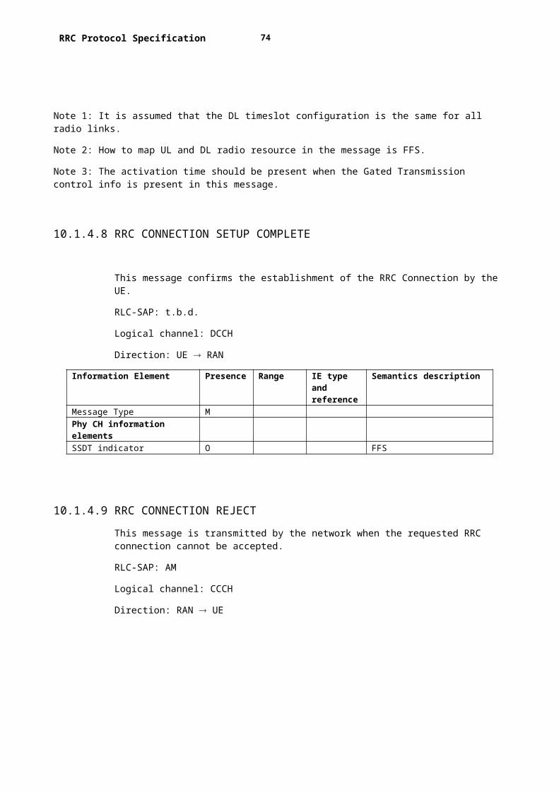
Note: The usage of this message for indicating the cell the UE will select in the DCH->RACH/FACH case, is FFS.
10.1.5.11 TRANSPORT FORMAT COMBINATION CONTROL
<Functional description of this message to be included here>
RLC-SAP: AM or UM.
Logical channel: DCCH
Direction: RANUE
Information Element Presence Range IE type and reference
Semantics description
Message Type MTrCH information elementsTFC subset M For uplink DCH's multiplexed
onto a CCTrCH
10.1.6 System Information Messages
10.1.6.1 SYSTEM INFORMATION
<Functional description of this message to be included here>
RLC-SAP: t.b.d.
Logical channel: BCCH or DCCH or CCCH
Direction: RAN UE
NOTE: The division of the system information into messages is FFS.
74 RRC Protocol Specification

Information Element Presence Range IE type and reference
Semantics description
Message Type MCN information elementsPLMN Identity MCN information 1 to
<maxCNdomains>
Send CN information for each CN domain. Information must be included for at least one core network domain type.
CN domain identity M NAS system information MRAN mobility information elementsRRA identity 1 to
<maxRRAcount>
Information for periodic cell and RRA update
M
Cell identity M The necessity and usage of cell identity is FFS.
Cell selection and re-selection info
M
UE information Uplink access control info MCPCH parameters O For all UE's assigned any
CPCH set in this cellUE Timers & Counters MDRAC information 0 to
<maxDRACclasses>
DRAC information is sent for each class of terminal
Transmission probability Maximum bit ratePhyCH information elements
Frequency info OPrimary CPCCH Info O
RACH information 1 to <maxRACHcount>
PRACH info M PRACH power control info MFACH information 1 to
<maxFACHcount>
Secondary CCPCH info MPCH information 1 to
<maxPCHcount>
Secondary CCPCH info MMeasurement information elementsMeasurement Identity Number MMeasurement Type OMeasurement reporting mode OPeriodical reporting criteria C-perRepIntra-frequency measurement information
C - Intrafreq
75 RRC Protocol Specification

Intra-frequency cell info M Measurement object Intra-frequency measurement quantity
M
Intra-frequency measurement reporting criteria
O
Intra-frequency measurement reporting quantity
O
Intra-frequency reporting quantity for RACH reporting
C -RACHrep
Inter-frequency measurement information
C - Interfreq
Inter-frequency cell info Measurement object Inter-frequency measurement quantity
O
Inter-frequency measurement reporting quantity
O
Inter-frequency measurement reporting criteria
M
Inter-system measurement information
C - Intersys
Inter-system cell info Measurement object Inter-system measurement quantity
M
Inter-system measurement reporting quantity
O
Inter-system measurement reporting criteria
M
Condition Explanation
Intersys Measurement type=Inter system measurement
Interfreq Measurement type=Inter frequency measurement
Intrafreq Measurement type=Intra frequency measurement
PerRep Periodical reporting specified
RACH-rep This information element is only included if RACH reporting is indicated in the reporting criteria
Range Bound Explanation
MaxCNdomains Maximum number of CN domains
MaxRRAcount Maximum number of RRA's in a cell
MaxDRACclasses Maximum number of UE classes which would require different DRAC parameters
MaxRACHcount Maximum number of RACH's
MaxFACHcount Maximum number of FACH's mapped onto secondary CCPCH's
76 RRC Protocol Specification
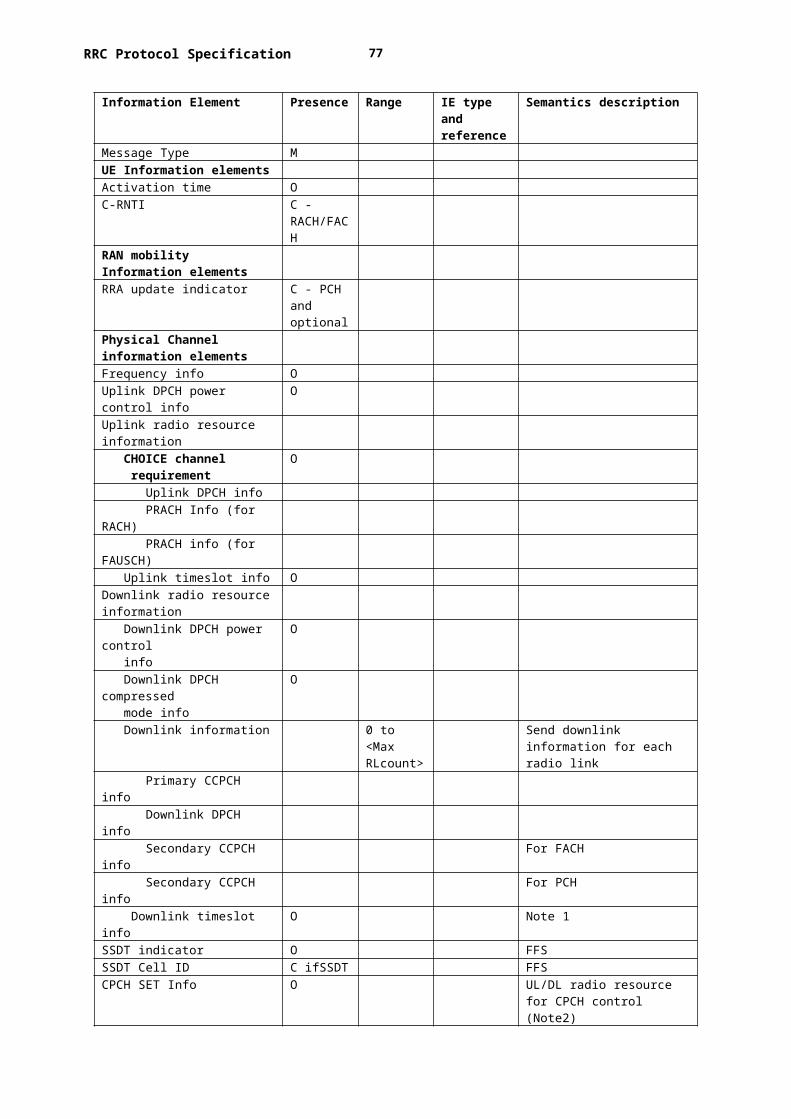
MaxPCHcount Maximum number of PCH's mapped onto secondary CCPCH's
MaxIntraFreqCount Maximum number of intra frequency measurement control
MaxInterFreqCount Maximum number of inter frequency measurement control
MaxInterSysCount Maximum number of inter system measurement control
MaxMeasObjCount Maximum number of Measurement Objects
Note 1: The usage of Measurement identity number in this message is FFS.
Note 2: The split of parameters into several System Information message X is FFS.
Note 3: How to map UL and DL radio resource in the message is FFS.
10.1.7 Other Messages
10.1.7.1 UE CAPABILITY INFORMATION
<Functional description of this message to be included here>
RLC-SAP:UM
Logical channel: DCCH
Direction: UE RAN
77 RRC Protocol Specification

Information Element Presence Range IE type and reference
Semantics description
Message Type MCN information elementsNAS message M Includes the CN capability
informationUE information elementsPower control capability MCode resource capability MUE mode capability MTransport CH support capability OCiphering capability MMacro diversity capability M
Other information elementsInter-system message O Includes inter-system
classmark
10.1.7.2 UE CAPABILITY INFORMATION CONFIRM
<Functional description of this message to be included here>
RLC-SAP: UM
Logical channel: DCCH
Direction: RAN UE
Information Element Presence Range IE type and reference
Semantics description
Message Type M
10.1.7.3 DIRECT TRANSFER
<Functional description of this message to be included here>
RLC-SAP: AM
Logical channel: DCCH
Direction: both
Information Element Presence Range IE type and reference
Semantics description
Message Type MCN information elementsCN domain identity MNAS message MMeasurement information elementsMeasured results O
78 RRC Protocol Specification
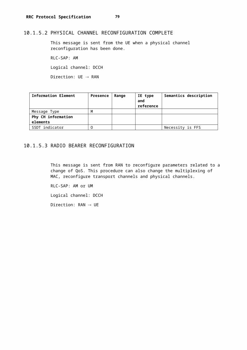
10.1.7.4 SECURITY CONTROL COMMAND
RLC-SAP: t.b.d.
Logical channel: DCCH
Direction: RAN to UE
Information Element Presence Range IE type and reference
Semantics description
Message Type MCN Information elementsCN domain identity M Indicates which cipher key is
ApplicableRB Information elementsRadio bearer identity 1 to
<maxReconRBs>
Radio bearer identity 0 indicates the signalling link and is always present
UE information elementsActivation Time M Start of the new ciphering
configuration in uplink for all the radio bearers
Range Bound Explanation
MaxReconRBs For each radio bearer that is reconfigured
10.1.7.5 SECURITY CONTROL RESPONSE
RLC-SAP: t.b.d.
Logical channel: DCCH
Direction: UE to RAN
Information Element Presence Range IE type and reference
Semantics description
Message Type MRB Information elementsRadio bearer identity 1 to
<maxReconRBs>
Radio bearer identity 0 indicates the signalling link and is always present
UE information elementsActivation Time M Start of the new ciphering
configuration in uplink for all the radio bearers
Range Bound Explanation
MaxReconRBs For each radio bearer that is reconfigured
79 RRC Protocol Specification
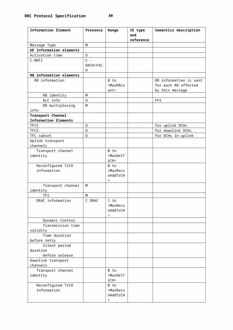
10.2 Information element functional definitions
10.2.1 CN Information elements
10.2.1.1 CN domain identity
Points out the core network domain (e.g. IP or PSTN/ISDN CN domain).
10.2.1.2 NAS binding info
A field with non-access stratum information to bind a RAB to the non-access stratum. This information is transparent to RRC.
10.2.1.3 NAS message
A non-access stratum message to be transferred transparently through RAN.
10.2.1.4 NAS system information
System information that belongs to the non-access stratum (e.g. LAC, RA code etc). This information is transparent to RRC.
10.2.1.5 PLMN identity
Information Element/Group name
Presence Range IE type and reference
Semantics description
MCC, Mobile Country Code MMNC, Mobile Network Code M
10.2.2 RAN mobility Information elements
10.2.2.1 Cell identity
Identity of a cell within a PLMN.
Note: The necessity and usage of this information element is FFS.
10.2.2.2 Cell selection and re-selection info
Information Element/Group name
Presence Range IE type and reference
Semantics description
Standby allowed reception level (dBm)
M The usage of these parameters needs clarification FFS.
Standby prohibited reception level (dBm)
M
Threshold for Cell Re-selection (dB)
M
Allowed reception SIR (dB) MRadio link timeout
80 RRC Protocol Specification
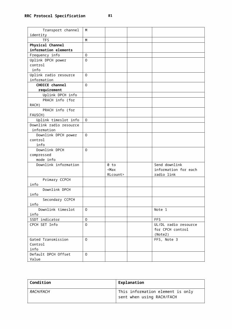
10.2.2.3 Information for periodic cell and RRA update
This information element indicates information to support mechanisms for periodical cell/RRA update procedures. It is mapped on System Information message.
Information Element/Group name
Presence Range IE type and reference
Semantics description
T_periodical_cell_update M Value “0” indicated no periodical Cell Update mechanism activated.
T_periodical_RRA_update M Value “0” indicated no periodical RRA Update mechanism activated.
10.2.2.4 RRA identity
Gives the identity of the RAN Registration Area. It can be used to indicate to the UE which RRA it shall use in case of overlapping RRAs.
10.2.2.5 RRA update indicator
When present in a message, it instructs the UE to start to update its location on RRA level.
10.2.3 UE Information elements
10.2.3.1 Uplink access control info
Information Element/Group name
Presence Range IE type and reference
Semantics description
Access class M FFSDynamic persistence level M FFS
10.2.3.2 C-RNTI info
81 RRC Protocol Specification
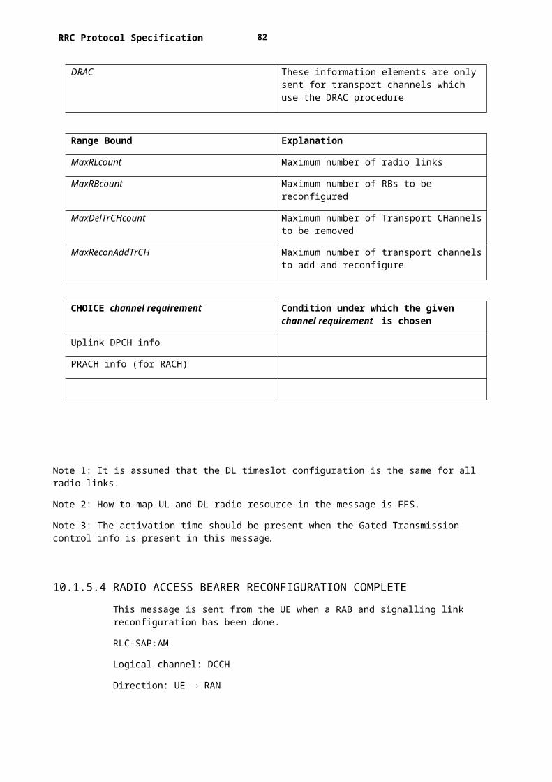
Information Element/Group name
Presence Range IE type and reference
Semantics description
c-RNTI The controlling RNC RNTI identifies an UE having a RRC connection within an controlling RNC.
DL scrambling code C if many c-RNTIs
Identifies the cell in which the c-RNTI applies.
10.2.3.3 S-RNTI
The serving RNC RNTI is allocated to an UE having a RRC connection and identifies the UE within its serving RNC.
10.2.3.4 SRNC identity
Identifies the serving RNC for an UE having an RRC connection.
10.2.3.5 Initial UE identity
This information element identifies the UE at a request of an RRC connection.
Information Element/Group name
Presence Range IE type and reference
Semantics description
CHOICE UE Identity M IMSI International Mobile
Subscriber Identity TMSI + LAI Temporary Mobile Subscriber
Identity and Location Area Identity
P-TMSI + RAI Packet Temporary Mobile Subscriber Identity and Routing Area Identity
IMEI International Mobile Subscriber Identity
CHOICE UE Identity Condition under which the given UE identity is used
IMSI
TMSI+LAI
P-TMSI+RAI
IMEI
[Note: The use of these identities is pending confirmation from WG1 that the RACH can support the required payload when these types of ID are used]
.
82 RRC Protocol Specification
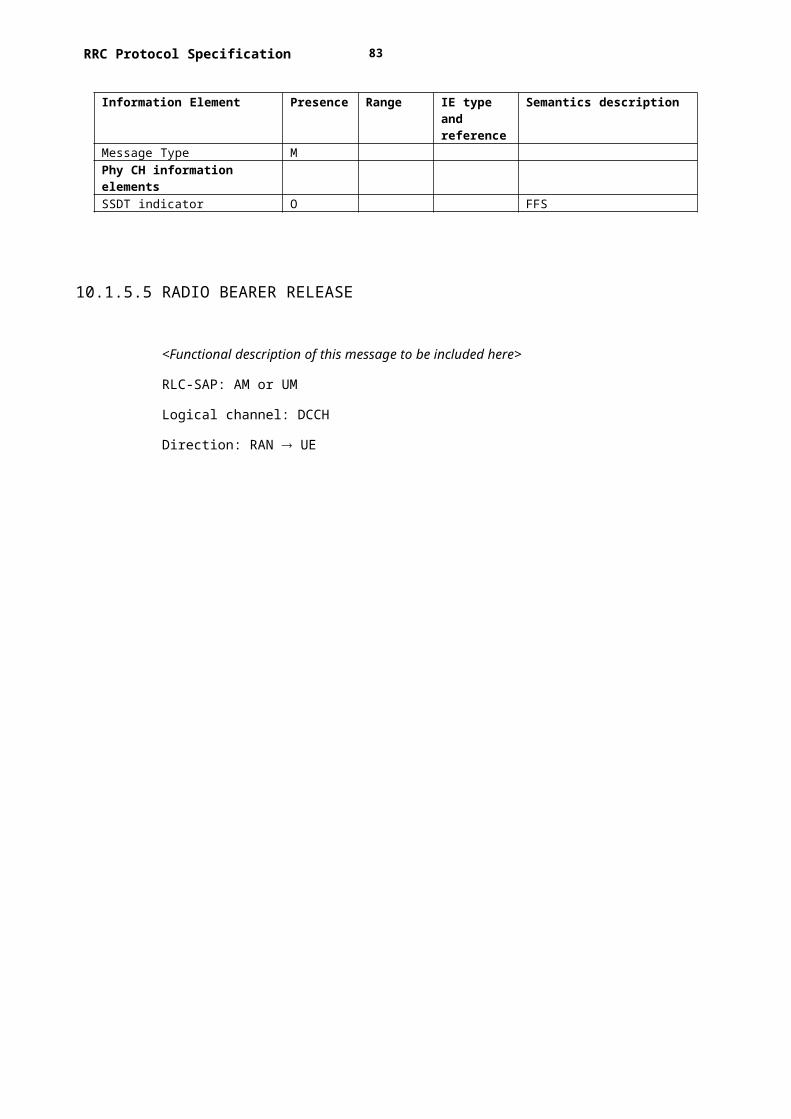
10.2.3.6 Activation time
Activation Time defines the frame number (or offset to some known frame number) in which the operation/changes caused by the related message should be executed.
Current assumption is that a connection based CFN (Connection Frame Number) that is known by MS and SRNC could be used.
10.2.3.7 Wait time
Wait time defines the time period the UE has to wait before repeating the rejected procedure.
10.2.3.8 Control-only-state timer
This IE indicates for how long the UE shall stay in the control-only-state.
Editors note: the exact usage of this IE needs some clarification.
10.2.3.9 Paging record
Information Element/Group name
Presence Range IE type and reference
Semantics description
Paging originator M Enumerated (RAN,CN)
Paging cause C isCNCN domain identity C isCNCHOICE Identity M IMSI TMSI P-TMSI Connected mode ID S-RNTI M SRNC identity M
Condition Explanation
isCN This information element is included where the page is originated from the CN.
CHOICE Identity Condition under which the given Identity is chosen
IMSI For idle mode pages
TMSI For idle mode pages
P-TMSI For idle mode pages
Connected mode ID For connected mode pages
83 RRC Protocol Specification

10.2.3.10 Establishment cause
Cause for an RRC connection establishment request (originating call, emergency call, paging response, location update request, forward inter-system handover etc).
10.2.3.11 Release cause
Cause for release of RRC connection.
10.2.3.12 Rejection cause
Cause for rejection of RRC connection establishment request.
10.2.3.13 Paging cause
Cause for a CN originated page.
Editors note: The usage of this IE needs further clarification.
10.2.3.14 Initial UE capability
This is the UE capability information given in the RRC connection request message. The exact type of information is FFS.
Information Element/Group name
Presence Range IE type and reference
Semantics description
Support for Transport CH O Indicates which transport channels are supported
10.2.3.15 Power control capability
Information Element/Group name
Presence Range IE type and reference
Semantics description
Transmission power capability M
10.2.3.16 Code resource capability
Information Element/Group name
Presence Range IE type and reference
Semantics description
DL multi-code capabilityUL multi-code capabilityDL Spreading factor capabilityUL Spreading factor capability
84 RRC Protocol Specification
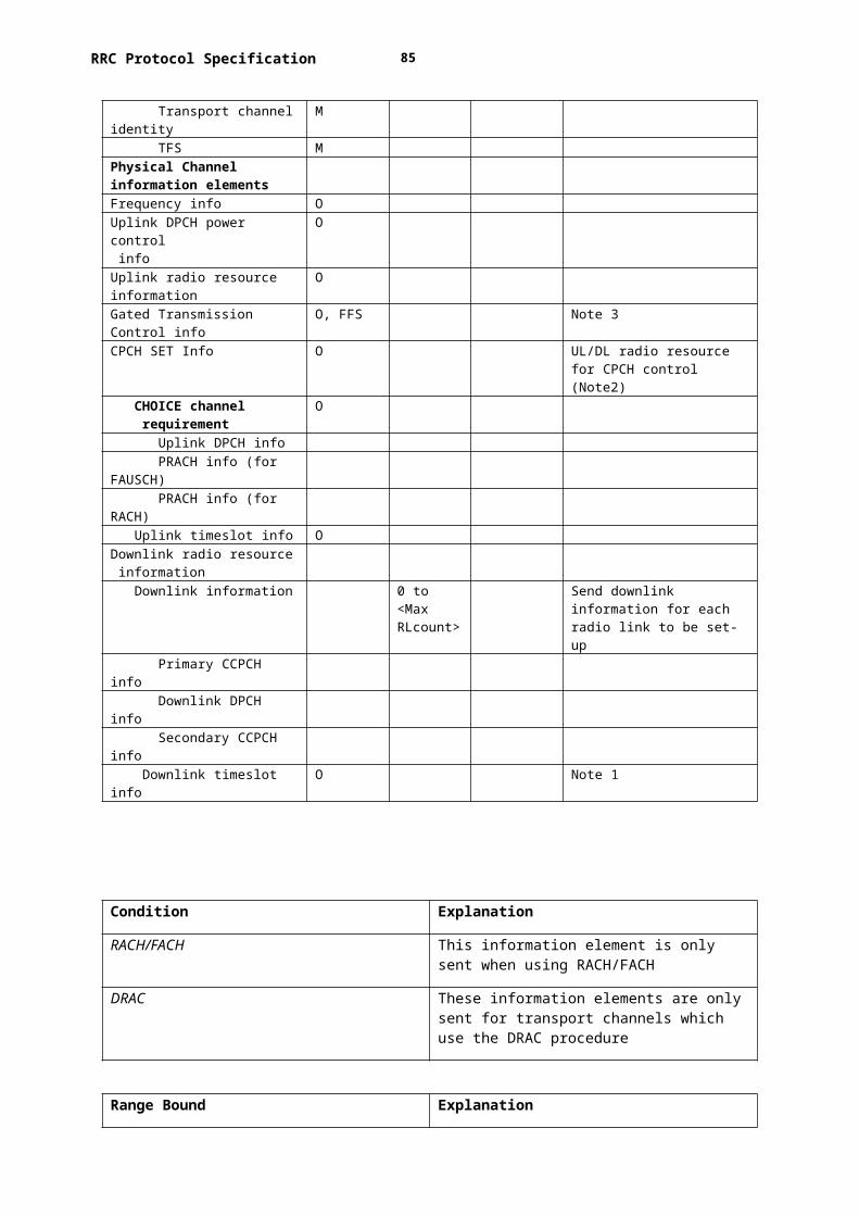
10.2.3.17 UE mode capability
Information Element/Group name
Presence Range IE type and reference
Semantics description
System capability 0 to <maxSystemCount>
Enumerated (UMTS, GSM, Others)
UMTS capability 0 to <maxModecount>
Enumerated
Chip rate capabilityRadio Frequency capabilityVariable duplex distance capability
Range Bound Explanation
MaxSystemCount Maximum number of Systems supported by the UE
maxModeCount Maximum number of UMTS modes supported by the UE
10.2.3.18 Transport channel support capability
Information Element/Group name
Presence Range IE type and reference
Semantics description
Maximum number of DCHs IntegerSupport for Transport CH
10.2.3.19 Ciphering capability
Information Element/Group name
Presence Range IE type and reference
Semantics description
Ciphering Algorithm capability M Enumerated
85 RRC Protocol Specification

10.2.3.20 Macro diversity capability
Information Element/Group name
Presence Range IE type and reference
Semantics description
Maximum number of RLs M Integer
10.2.3.21 Cell update cause
Indicates the cause for s cell update. Examples of causes are cell reselection and periodic cell update .
10.2.3.22 RRA update cause
Indicates the cause for s RRA update. Examples of causes are change of RRA and periodic RRA update .
10.2.3.23 Number of Quick Repeat
Indicates the number of quick repeat for RRC Connection Release Complete message .
10.2.3.24 Inter-system handover failure cause
The purpose of this IE is to provide a reason for the failure of the Inter-system handover.
10.2.3.25 Transmission probability
Indicates the probability for a mobile to be allowed to transmit on a DCH controlled by DRAC procedure.
10.2.3.26 Maximum bit rate
Indicates the maximum user bit rate allowed on a DCH controlled by DRAC procedure for the transmission period (Transmission time validity).
86 RRC Protocol Specification
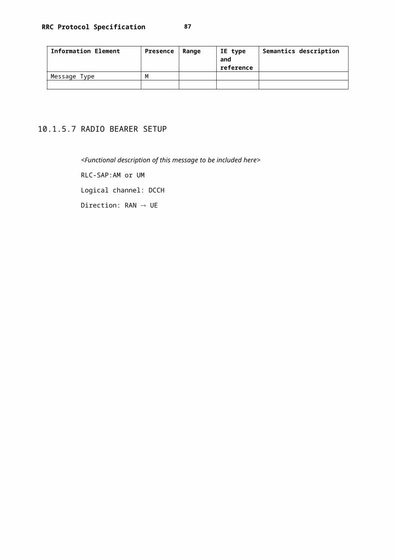
10.2.3.27 Capability Update Requirement
This IE indicates to the UE, which is capable of inter-system handover, whether it should send a complete update of its capabilities in the given system (e.g. GSM) immediately after having established an RRC connection.
Information Element/Group name
Presence Range IE type and reference
Semantics description
System M Enumerated (GSM,..)
Early Capability Update M Boolean
10.2.3.28 UE Timers and Counters
This information element indicates timers and Maximum values of each counter used in UE.
Information Element/Group name
Presence Range IE type and reference
Semantics description
Timer_await_RRC_connection_setup
M
Timer_Maximum_number_of_ RRC_connection_setup_re-trys_since_first_attempt
M
Maximum value of Counter_Max_Number_of_connection_setup_transmissions_in_this_cell
M
Timers_out_of_service_area MTimer_await_cell_update_confirm MTimer_await_RRA_update_confirm
M
Maximum value of Counter_await_cell_update_confirm
M
Maximum value of Counter_await_RRA_update_confirm
M
10.2.3.28 Re-establishment function support
This parameter indicats whether UE should require RRC connection re-establishment procedure in case of an impermanent disconnection, and this is to inform from UE to RAN in advance.
10.2.3.29 Re-establishment complete timer
This parameter indicats the maximamu waiting time until when RAN should receive RRC CONNECTION RE-ESTABLISHMENT REQUEST from UE at the break of the radio connection. UE starts this timer when it detects disconnection of a line. When RRC connection re-establishment is completed, UE stops the timer. When the timer is expired, UE releases radio resources.
87 RRC Protocol Specification
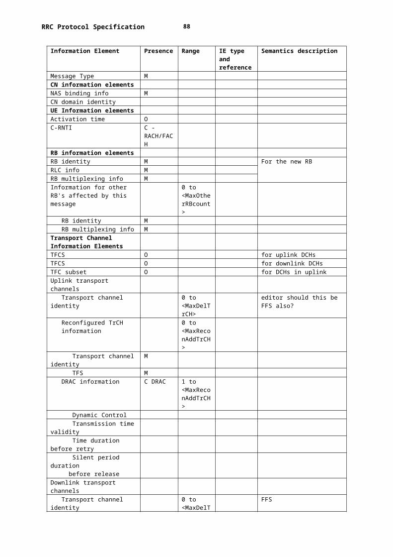
10.2.3.30 AM_RLC error indication
Indicates AM_RLC unrecoverable error occurred on c-plane in the UE.
10.2.3.31 RLC re-configuration indicator
This IE is used to re-configure AM RLC on c-plane.
10.2.4 Radio Bearer Information elements
10.2.4.1 RB identity
An identification number for the RB affected by a certain message.
10.2.4.2 RLC info
Information Element/Group name
Presence Range IE type and reference
Semantics description
Uplink RLC info RLC mode M enumerated
(Acknowledged, Non Acknowledged or Transparent mode data transfer. )
Note 1
PU size O Integer Transmission RLC discard C-NonTr Transmission window size C-ACK Integer Polling info C-ACK
Downlink RLC info RLC mode M enumerated
(Acknowledged, Non Acknowledged or Transparent mode data transfer. )
Note 1
In-sequence delivery O Boolean PU Size M Integer Reception RLC discard timer C- timer Receiving window size (FFS - Note 2)
C-ACK Integer
Downlink RLC status Info C-ACK
Condition Explanation
Timer This IE is only sent if timer based discard is used without explicit signalling
NonTr This IE is only sent when the RLC is non-
88 RRC Protocol Specification
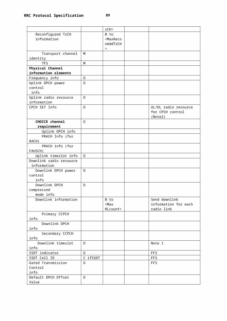
transparent
Ack This IE is only sent when the RLC uses acknowledged mode
Note 1: It is FFS if this IE always includes the same parameter values for both uplink and downlink RLC.
Note 2:It is FFS whether “Receiving window size” is necessary or not.
10.2.4.2.1 RLC Mode
Indicates if Acknowledged, Unacknowledged or Transparent mode RLC should be used.
10.2.4.2.2 In-sequence delivery
Indication if RLC should preserve the order of higher layer PDUs when these are delivered.
10.2.4.2.3 PU size
Indicates the size of RLC Payload Units.
10.2.4.2.4 Transmission RLC Discard
Information Element/Group name
Presence Range IE type and reference
Semantics description
SDU Discard Mode M Different modes for discharge the RLC buffer on the transmitter side;Timer based with explicit signalling, Timer based without explicit signalling or Discard after Max_DAT retransmissions. For unacknowledged mode only Timer based without explicit signalling is applicable.
Timer_discard C-timer Elapsed time before a SDU is discarded.
Max_DAT C-discard Number of retransmissions of a PU before a SDU is discarded.
Condition Explanation
Timer This IE is only sent if timer based discard is used without explicit signalling
Discard This IE is only sent when the SDU discard technique is to discard SDU's after a given number of PU re-transmissions
89 RRC Protocol Specification

10.2.4.2.5 Transmission window size
Maximum number of RLC PUs sent without getting them acknowledged. This parameter is needed if acknowledged mode is used.
10.2.4.2.6 Receiving window size (FFS)
Maximum number of RLC PUs allowed to be received. This parameter is needed if acknowledged mode is used.(Necessity is FFS.)
10.2.4.2.7 Polling info
Information Element/Group name
Presence Range IE type and reference
Semantics description
Timer_poll_prohibit O Minimum time between pollsTimer_poll O Started when poll is transmitted.
New poll when timer expires and no STATUS received.
Poll_PU O Poll at every Poll_PU PUPoll_SDU O Poll at every Poll_SDU SDULast transmission PU poll O Indicates if poll at last PU in
transmission bufferLast retransmission PU poll O Indicates if poll at last PU in
retransmission bufferPoll_Window O Poll at Poll_Window % of
transmission windowTimer_poll_periodic O Timer for periodic polling
Note: At least one or more parameters are necessary when polling info is sent.
10.2.4.2.8 Reception RLC discard Timer
Elapsed time before a SDU is discarded. Only present if timer based discard mode without explicit signalling is chosen.
10.2.4.2.9 Downlink RLC STATUS info
Information Element/Group name
Presence Range IE type and reference
Semantics description
Timer_Status_Prohibit O Minimum time between STATUS reports
Timer_EPC O Timer for EPCMissing PU Indicator O Indicates if UE should send a
STATUS report for each missing PU that is detected
Timer_STAUS_periodic O Timer for periodic STATUS reports
10.2.4.3 Signalling link type
The purpose of the Signalling Link Type information element is to indicate the RLC parameters needed for the signalling link.
Each possible value of Signalling Link Type information element refers to a predefined set of parameters. Details FFS.
90 RRC Protocol Specification

10.2.4.4 RB multiplexing info
A multiplexing option for each possible transport channel this RB can be multiplexed on.
Information Element/Group name
Presence Range IE type and reference
Semantics description
Information for each multiplexing option
1 to <maxMuxOptionsCount>
Uplink multi-plexing Transport channel identity O This is the ID of a transport
channel that this RB could be mapped onto.
Logical channel identity O This parameter is used to distinguish logical channels multiplexed by MAC on a transport channel.
MAC logical channel priority O This includes both priority between different users traffic when using a common or shared channel, and between different RBs (or logical channels) traffic for a certain user. Different priorities for one users´ RBs are mapped (through the MAC´s T and C/T MUXes) to the TFC selection algorithm.
[Note: Usage and precise meaning of this is FFS.]
Downlink multi-plexing Transport channel identity O Logical channel identity O
Note: The necessity of dividing RB multiplexing into in uplink and downlink is FFS.
10.2.5 Transport CH Information elements
10.2.5.1 Transport Format Combination Set
Indicates the allowed combinations of already defined Transport formats.
Information Element/Group name
Presence Range IE type and reference
Semantics description
Transport format combination 1 to 1024 Transport Format Number 1 to
maxTrChInteger(0..31)
The integer number is a reference to the Dynamic transport format information, that arrived at that position in the Transport Format Set for that transport channel. The first instance of this IE corresponds to the first transport channel and so on.
Range Bound Explanation
91 RRC Protocol Specification
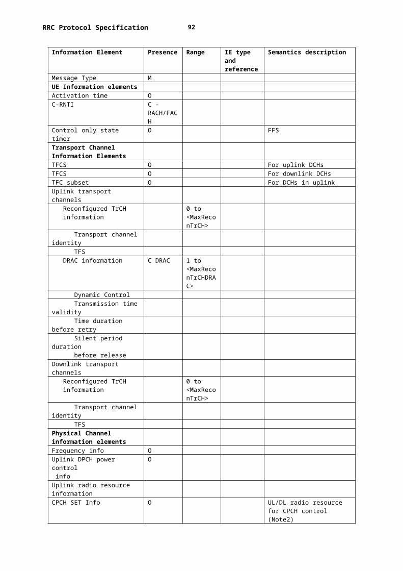
MaxTrCh Maximum number of transport channels that could be allocated to one UE.
10.2.5.2 Transport Format Combination Subset
Indicates which Transport format combinations in the already defined Transport format combination set that are allowed.
Information Element/Group name
Presence Range IE type and reference
Semantics description
CHOICE Subset representation M Minimum allowed Transport format combination number
Integer(0..1023)
The integer number is a reference to the Transport format combination, that arrived at that position in the Transport Format Combination Set.
Transport format combination 1 to <maxTFCcount>
Integer(0..1023)
The integer number(s) is a reference to the Transport format combination, that arrived at that position in the Transport Format Combination Set.
Range Bound Explanation
MaxTFCcount Maximum number of Transport Format Combinations that could be sent as the limited set that the UE is allowed to use.
10.2.5.3 Transport channel identity
This information element is used to distinguish transport channels (both common and dedicated transport channels).
10.2.5.4 Transport Format Set (TFS)
Information Element/Group name
Presence Range IE type and reference
Semantics description
Transport block size(s) (dynamic)Transport Block Set Size(s) (dynamic)Transmission time interval (semi-static)Type of channel coding (semi-static)Rate matching (semi-static)
10.2.5.5 Dynamic Control
92 RRC Protocol Specification

Indicates if this transport channel is controlled by DRAC procedure or not.
10.2.5.6 Transmission time validity
Indicates the duration for which permission is granted on a DCH controlled by DRAC procedure.
10.2.5.7 Time duration before retry
Indicates the time duration before retrying to get the transmission permission on a DCH controlled by DRAC procedure, in case permission has not been granted.
10.2.5.8 Silent period duration before release
Indicates the maximum silent period duration before releasing the resource. This parameter may be merged with the Fkp-b parameter defined in the ‘Transmission stop and resumption control’ procedure defined in [1].
(Note: [1] RAN/WG1 S1.14 document)
10.2.5.9 Idle mode PCH info
This IE includes the information required in order to read the PCH transport channel.
Information Element/Group name
Presence Range IE type and reference
Semantics description
Paging message duration M Integer This indicates the number of 10 ms frames over which a paging message is transmitted.
DRX Cycle length M 0 to <maxCNdomains>
Integer This indicates the frequency with which paging occasions occur
Range Bound Explanation
MaxCNdomains Maximum number of CN domains
10.2.5.10 Coded Composite Transport Channel Identity
Parameters REFERENCE TYPE NOTETDD
CCTrCH identity M Designate coded composit transport channels
93 RRC Protocol Specification

10.2.6 Physical CH Information elements
10.2.6.1 Frequency info
Information Element/Group name
Presence Range IE type and reference
Semantics description
RF Channel Number M A unique identifier for the channel raster and its associated parameters (as described by the other parameters within this info element)
Raster Position O Provided to enable the definition of permitted carrier frequency associated to the specific RF Channel Number parameter
Duplex distance OChip rate ORF Channel Type O enumerated Identifies whether the RF
Channel Number corresponds to uplink/ downlink only
10.2.6.2 Primary CCPCH info
Information Element/Group name
Presence Range IE type and reference
Semantics description
DL scrambling code O DL scrambling code used for Primary CCPCH
STTD indicator O
10.2.6.3 Secondary CCPCH info
Information Element/Group name
Presence Range IE type and reference
Semantics description
DL scrambling code C - DLscode
STTD indicator OChannelization code M
Condition Explanation
DLscode The DL scrambling code information element is
94 RRC Protocol Specification

only sent if it is different from the DL scrambling code of the Primary CCPCH
10.2.6.4 PRACH info (for RACH)
Information Element/Group name
Presence Range IE type and reference
Semantics description
Access slot M 1 to <maxAccessSlots>
UpPTS spreading code M 1 to <maxPcodes>
UpPTS signature O 1 to <maxPsigs>
Range Bound Explanation
MaxAccessSlots Maximum number of allowed access slots for the UpPTS
MaxPcodes Maximum number of codes to use for spreading of the UpPTS. There is also a one to one mapping from UpPTS code to what scrambling code to use for the message part.
MaxPsigs Maximum number of allowed UpPTS signatures.
MaxRates Maximum number of rates or SF that are allowed to use on the data part (I-branch) in the message part of the random access
95 RRC Protocol Specification

10.2.6.5 PRACH power control info
Information Element/Group name
Presence Range IE type and reference
Semantics description
UL target SIR MPrimary CCPCH DL TX power MUL interference MConstant value M Note: it should be clarified
whether this is the same as UL target SIR.
Power offsetP0 M Power step when no acquisition indicator is received
Power offsetP1 M Power step when negative acquisition is received
NOTE: The usage of these parameters needs clarification and are also dependent on the WG1 RACH discussions.
10.2.6.6 Uplink DPCH info
Information Element/Group name
Presence Range IE type and reference
Semantics description
UL scrambling code M What short or long uplink scrambling code a certain UE should use
10.2.6.7 Uplink DPCH power control info
Interference level measured for a frequency at the RAN access point used by UE to set DPCH initial output power.
Parameters REFERENCE TYPE NOTEUL target SIR M
10.2.6.8 Downlink DPCH info
Information Element/Group name
Presence Range IE type and reference
Semantics description
DL scrambling code C - DLscode
DL channelization code 1 to <maxDPCHcount>
Channelization codes to be used in the downlink for DPCH
Transmission diversity mode C-STTD
96 RRC Protocol Specification

10.2.6.9 Uplink timeslot info
Information Element/Group name
Presence Range IE type and reference
Semantics description
Slot number 1 to <maxSlotcount>
Timeslot to be used in uplink
Range Bound Explanation
MaxSlotcount Maximum number of slots
10.2.6.10 Downlink timeslot info
Information Element/Group name
Presence Range IE type and reference
Semantics description
Slot number 1 to <maxSlotcount>
Timeslot to be used in downlink
Range Bound Explanation
MaxSlotcount Maximum number of slots
10.2.6.11 PUSCH info
Parameters REFERENCE TYPE NOTE
PUSCH channelization code M Channelization code for PUSCH
For each PUSCH
Midamble Type M short or long midamble
PUSCH midamble shift M Midamble shift of the PUSCH
Timeslot M Timeslot of the PSUCH
Superframe offset O Offset of the first PUSCH transmission in a 72 Superframe
Repetition Period M Repetition period of the
97 RRC Protocol Specification

PUSCH in the 72 Superframe
Repetition length O Length of the allocation for each repetition
TFCI presence O coding for a TFCI field in a PUSCH
10.2.6.12 PDSCH info
Parameters REFERENCE TYPE NOTE
DL channelization code M Channelization codes to be used in the downlink for PDSCH
For each PDSCH
Midamble Type M short or long midamble
PDSCH midamble shift M Midamble shift of PDSCH
Timeslot M Timeslot of the PDSCH
Superframe offset O Offset of the first PDSCH transmission in a 72 Superframe
Repetition period M Repetition period of the PDSCH in the 72 Superframe
Repetition length O Length of the allocation for each repetition
TFCI presence O coding for a TFCI field in a PDSCH
10.2.6.13 Activation start time info
Parameters REFERENCE TYPE NOTE
Activation time O frame number indicates the begin of the allocation
10.2.6.14 Allocation duration info
Parameters REFERENCE TYPE NOTE
Allocation duration O frame numer indicates the end of the allocation
10.2.6.15 PUSCH power control info
98 RRC Protocol Specification
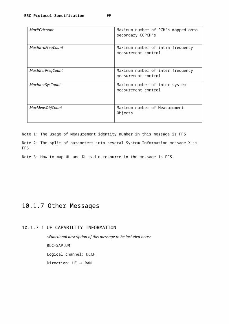
Parameters REFERENCE TYPE NOTE
PUSCH power control O power control parameter for PUSCH
10.2.6.11 SSDT indicator
This information element indicates the status (e.g. initiated/terminated) of the Site Selection
Diversity Transmit power control (SSDT). In the direction RAN to UE it is used to change the SSDT status. In the direction UE to RAN it is used to confirm the SSDT status by the UE. The parameter 'code word set' indicates how cell identities are coded (using many bits or few, values are long, medium, or short).
Information Element/Group name
Presence Range IE type and reference
Semantics description
Code Word Set M Enumerated (long, medium, short, SSDT off)
10.2.6.12 SSDT cell identity
This IE is used to associate a cell identity with a given radio link
Information Element/Group name
Presence Range IE type and reference
Semantics description
temporary id M
10.2.6.13 Gated Transmission Control info (FFS)
Information Element/Group name
Presence Range IE type and reference
Semantics description
Gating pattern M Enumerated (periodic, random- (FFS))
Gating rate M Enumerated (Full rate,1/3 , 1/5 or 0
Indicates gated transmission rate
99 RRC Protocol Specification

10.2.6.14 Default DPCH Offset Value
Indicates the default offset value within interleaving size at a resolution of 512chip (1/5 slot) to offset CFN in the UE. This is used to distribute discontinuous transmission periods in time and also to distribute NodeB-RNC transmission traffics in time. Even though the CFN is offset by DOFF, the start timing of the interleaving will be the timing that “CFN mod (interleaving size)”=0 (e.g. interleaving size: 2,4,8) in both UE and SRNC.
10.2.6.15 RF channel number priority
Information Element/Group name
Presence Range IE type and reference
Semantics description
RF channel number priority M Enable the setting of priority of the RF Channel Number parameter, to facilitate efficient system/ cell/ channel identification and selection processes
[Editor's note: a Liaison has been sent to determine whether this IE is necessary]
10.2.6.21 Downlink DPCH compressed mode info
This information element indicates the parameters of the downlink compressed mode to be used by the UE in order to perform inter-frequency measurements.
100 RRC Protocol Specification

Information Element/Group name
Presence Range IE type and reference
Semantics description
TGL M Transmission Gap length expressed in number of slots
CFN M Connection Frame Number when the first compressed frame starts
SN M Slot number when the transmission gap starts (within the CFN)
TGP M Transmission Gap Period indicates the number fo frames between two sets of consecutive compressed frames containing up to 2 transmission gaps
TGD M Transmission Gap distance indicates the number of frames between two consecutive transmission gaps within a transmission gap period.
PD M Total number of TGPs PCM M Power control mode during
the frame after the compressed frame. Indicates whether normal PC mode or compressed PC mode is applied
DeltaEb/No M Delta in DL Eb/No target value to be set in the UE during the compressed frames (Note 1)
DeltaEb/Noafter M Delta in DL Eb/No target value to be set in the UE one frame after the compressed frames (Note 1)
[Editors Note 1: The current assumptions is that the delta will be zero or positive]
10.2.6.22 Downlink DPCH power control information
This information element indicates the range of Eb/No target values and the initial Eb/No target value to be set in the UE on this physical, channel for the downlink closed loop power control.
Information Element/Group name
Presence Range IE type and reference
Semantics description
Initial Eb/No target value M Initial Eb/No value to be used for the DL closed loop power control.
Min Eb/No target value M Minimum Eb/No value that can be set by the DL closed loop power control.
Max Eb/No target value M Maximum Eb/No value that can be set by the DL closed loop power control.
101 RRC Protocol Specification
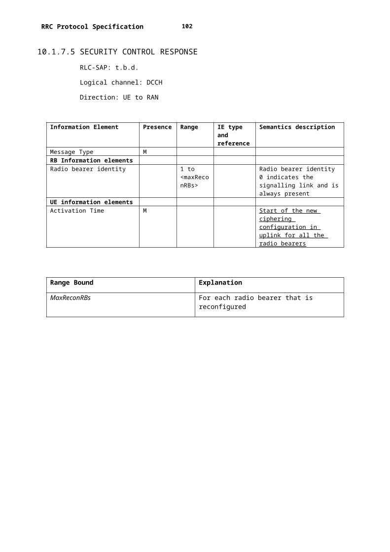
10.2.7 Measurement Information elements
10.2.7.1 Measurement Identity Number
A reference number that is used by the RAN at modification and release of the measurement, and by the UE in the measurement report.
10.2.7.2 Measurement Command
One out of three different measurement commands
Setup: Setup a new measurement.
Modify: Modify a previously specified measurement, e.g. change the reporting criteria.
Release: Stop a measurement and clear all information in the UE that are related to that measurement.
10.2.7.3 Measurement Type
One of the types from a predefined list where each type describes what the UE shall measure. The types are:
Intra-frequency measurements
Inter-frequency measurements
Inter-system measurements
Traffic volume measurements
Quality measurements
UE internal measurement
10.2.7.4 Reference time difference to cell
The reference time difference to cell indicates the time difference between the primary CCPCH of the current cell and the primary CCPCH of a neighbouring cell. It is notified to UE by System Information or Measurement Control message.
In case of macro-diversity the reference is the primary CCPCH of one the cells used in the active set.
Editors note: Exactly how the reference cell is pointed out in this case in the messages is FFS.
10.2.7.5 Measured time difference to cell
102 RRC Protocol Specification

The measured time difference to cell indicates the time difference which is measured by UE between the primary CCPCH of the current cell and the primary CCPCH of a neighbouring cell. It is notified to SRNC by Measurement Report message or Measurement Information Element in other RRC messages.
In case of macro-diversity the reference is the primary CCPCH of one the cells used in the active set.
Editors note: Exactly how the reference cell is pointed out in this case in the messages is FFS.
10.2.7.6 Measurement reporting mode
Contains the type of Measurement Report transfer mode and the indication of periodical/event trigger.
Information Element/Group name
Presence Range IE type and reference
Semantics description
Measurement Report Transfer Mode
M enumerated (Acknowledged / Unacknowledged)
Periodical Reporting / Event Trigger Reporting Mode
M enumerated (Periodical reporting / Event trigger)
10.2.7.7 Intra-frequency cell info
Contains the measurement object information for an intra-frequency measurement.
Information Element/Group name
Presence Range IE type and reference
Semantics description
Primary CCPCH info MPrimary CCPCH DL TX power OUL load O FFSSFN Measurement Indicator M
10.2.7.8 Inter-frequency cell info
Contains the measurement object information for an inter-frequency measurement.
103 RRC Protocol Specification

Information Element/Group name
Presence Range IE type and reference
Semantics description
Frequency info MPrimary CCPCH info MPrimary CCPCH DL TX power O FFSUL load O FFSReference time difference to cell
O FFS
10.2.7.9 Inter-system cell info
Contains the measurement object information for an inter-system measurement.
Information Element/Group name
Presence Range IE type and reference
Semantics description
System type M enumerated (GSM,..)
System specific measurement info
enumerated (frequency, timeslot, colour code, output power.)
10.2.7.10 Traffic volume measurement object
Contains the measurement object information for a traffic volume measurement.
Information Element/Group name
Presence Range IE type and reference
Semantics description
Target Transport CH ID M
10.2.7.11 Quality measurement object (FFS)
(Note: Only the section is made.)
10.2.7.12 Intra-frequency measurement quantity
The quantity the UE shall measure in case of intra-frequency measurement. It also includes the filtering of the measurements.
measurements.
104 RRC Protocol Specification
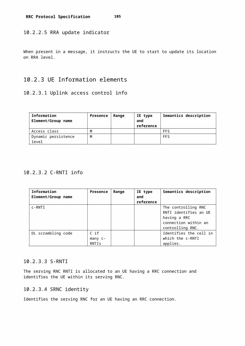
Information Element/Group name
Presence Range IE type and reference
Semantics description
Primary CCPCH RX Ec/I0 O One of these is mandatoryPrimary CCPCH RX SIR (RSCP/ISCP)
O FFS
Primary CCPCH RX power (RSCP)
O FFS
Path loss O FFSPath loss plus UL load O FFS
(Note: Above measurements except for Ec/Io are not concluded in WG1)
10.2.7.13 Inter-frequency measurement quantity (FFS)
The quantity the UE shall measure in case of inter-frequency measurement. It also includes the filtering of the measurements.
Information Element/Group name
Presence Range IE type and reference
Semantics description
Ec/I0 O FFS One of these is mandatoryDL Path loss O FFSSIR O FFSDL path loss plus UL interference
O FFS
Received signal code power (RSCP)
O FFS
10.2.7.14 Inter-system measurement quantity (FFS)
The quantity the UE shall measure in case of inter-system measurement. It also includes the filtering of the measurements.
Information Element/Group name
Presence Range IE type and reference
Semantics description
Ec/I0 O FFS One of these is mandatorySignal strength OPath loss O FFSColour code C - GSM
Condition Explanation
GSM This information element is only sent when the system being measured is a GSM system
105 RRC Protocol Specification

10.2.7.15 Traffic volume measurement quantity
Contains the measurement quantity information for a traffic volume measurement.
Information Element/Group name
Presence Range IE type and reference
Semantics description
RLC buffer payload M
(Note: If there is no other measurement quantity, this parameter can be removed since it can be implicitly known by UE.)
10.2.7.16 UE internal measurement quantity
The quantity the UE shall measure in case of UE internal measurement.
Information Element/Group name
Presence Range IE type and reference
Semantics description
UE Tx power O One of these is mandatoryUE RSSI O
10.2.7.17 Quality measurement quantity (FFS)
(Note: Only the section is made.)
10.2.7.18 Intra-frequency reporting quantity
Contains the reporting quantity information for an intra-frequency measurement.
Information Element/Group name
Presence Range IE type and reference
Semantics description
Primary CCPCH RX Ec/I0 OPrimary CCPCH RX SIR (RSCP/ISCP)
O FFS
Primary CCPCH RX power (RSCP)
O FFS
Path loss plus UL load O FFSMeasured time difference to cell ODL Transport CH BLER ODL Transport CH BER O FFSUE Transmission Power OUE Position OCell ID O FFS
106 RRC Protocol Specification

(Note: It is FFS whether the reporting quantity parameters used in different measurement types can be used commonly for all types of reporting quantity. If they can, only “Reporting Quantity” is enough instead of specifying 5 types of reporting quantity.)
10.2.7.19 Intra-frequency reporting quantity for RACH reporting
Contains the reporting quantity information for an intra-frequency measurement report, which is sent on the RACH.
Information Element/Group name
Presence Range IE type and reference
Semantics description
Primary CCPCH RX Ec/I0 OPrimary CCPCH RX SIR (RSCP/ISCP)
O FFS
Primary CCPCH RX power (RSCP)
O FFS
Path loss plus UL load O FFSMeasured time difference to cell ODL Transport CH BLER O FFSDL Transport CH BER O FFSUE Transmission Power O FFSUE Position O FFSCell ID O FFS
10.2.7.20 Inter-system reporting quantity (FFS)
(Note: Only the section is made.)
10.2.7.21 Inter-system reporting quantity (FFS)
(Note: Only the section is made.)
10.2.7.22 Traffic volume reporting quantity
Contains the reporting quantity information for a traffic volume measurement.
107 RRC Protocol Specification
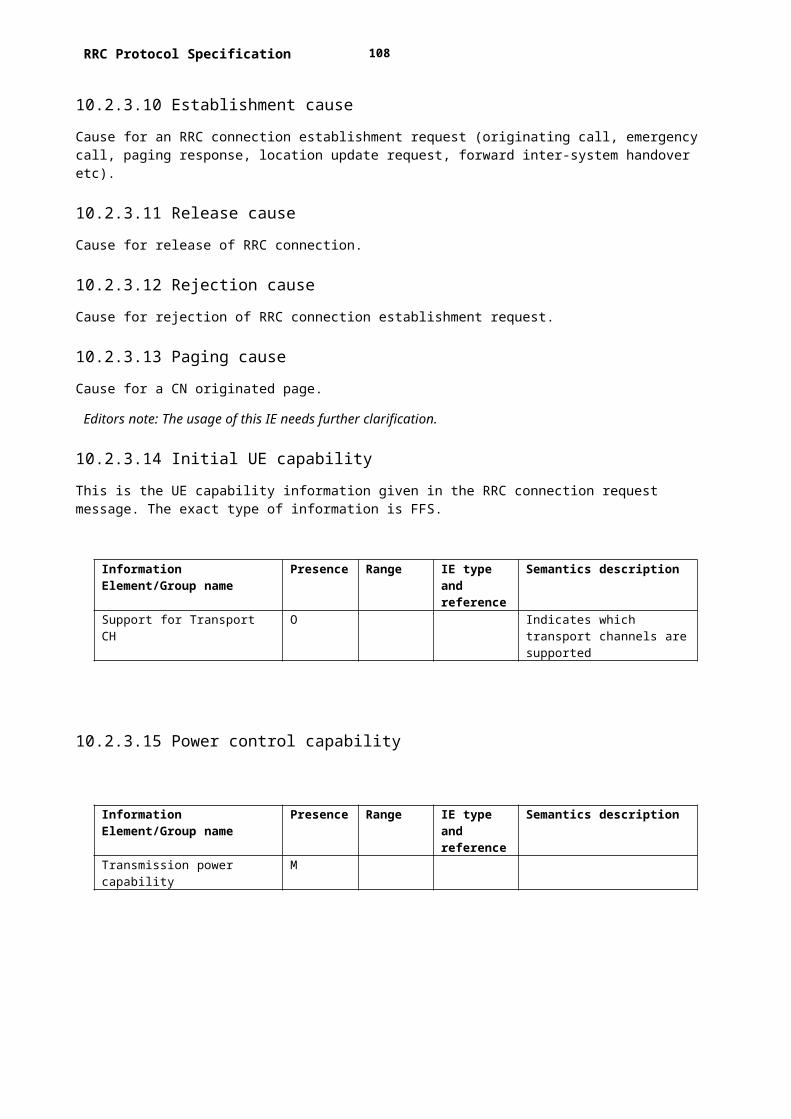
Information Element/Group name
Presence Range IE type and reference
Semantics description
RLC buffer payload for each RB ODL Transport CH BLER ODL Transport CH BER O FFSUE Transmission Power OUE Position OCell ID O FFS
(Note: It is FFS whether the reporting quantity parameters used in different measurement types can be used commonly for all types of reporting quantity. If they can, only “Reporting Quantity” is enough instead of specifying 5 types of reporting quantity.
10.2.7.23 Quality reporting quantity (FFS)
(Note: Only the section is made.)
10.2.7.24 Intra-frequency measurement reporting criteria
The triggering of the event-triggered reporting for an intra-frequency measurement. All events concerning intra-frequency measurements are labeled 1x where x is a, b, c….
Event 1a: A Primary CCPCH enters the Reporting Range [Note1]
Event 1b: A Primary CCPCH leaves the Reporting Range [Note2]
Event 1c: A Non-active Primary CCPCH becomes better than an active Primary CCPCH [Note3]
Event 1d: Change of best cell [Note4, 5]
Event 1e: Other types of ranking of Primary CCPCHs (FFS)
108 RRC Protocol Specification

Information Element/Group name
Presence Range IE type and reference
Semantics description
Max number of reporting cells M Common parameter for all events
RACH measurement reporting parameters
Group name
Maximum number of reported cells on RACH
M
Parameters required for each event
0 to <maxEventcount>
Event ID M 1a, 1b, 1c, 1d or 1e Triggering condition C - clause
0enumerated Indicates whether event shall
be triggered by:
-Active set cells only
-Monitored set cells only
-Both active set cells and monitored set cells
Reporting Range C - clause 1
In event 1a,1b
Hysteresis C & O - clause 2
In event 1a, 1b, 1c,1d
Reporting deactivation threshold
C - clause 3
In event 1a
Indicates the maximum number of cells allowed in the active set in order for event 1a to occur.
Value 0 indicates "not applicable".
Replacement activation threshold
C - clause 4
In event 1c
Indicates the minimum number of cells allowed in the active set in order for event 1c to occur.
Value 0 indicates "not applicable".
Time to trigger M Indicates the period of time between the timing of event detection and the timing of sending Measurement Report.
Amount of reporting M Measurement for the indicated Transport CH ID is “released” after the indicated amount of reporting from the UE itself.
FFS Reporting interval M Indicates the interval of
periodical reporting when such reporting is triggered by an event. A zero value indicates that event triggered periodical reporting shall not be applied.
109 RRC Protocol Specification

Condition Explanation
Clause 0 This parameter is only sent in event 1a,1b, 1e, 1f
Clause 1 This parameter is only sent in event 1a,1b
Clause 2 This parameter is only sent in event 1a,1b, 1c,1d
Clause 3 This parameter is only sent in event 1a
Clause 4 This parameter is only sent in event 1c
[Note1: whether or not PCCPCH can be active is FFS]
[Note2: whether or not PCCPCH can be non-active is FFS]
[Note3: Details are FFS: It has been suggested to divide this event into two cases; I) a non-active PCCPCH exceeds the weakest active PCCPCH, II) a non-active PCCPCH exceeds the strongest active PCCPCH]
[Note4: When best PCCPCH in active set changes, all active cells are reported.]
[Note5: Whether this event can result in the reporting of non-active cells in addition to active cells is FFS.]
10.2.7.25 Inter-frequency measurement reporting criteria (FFS)
The triggering of the measurement report, e.g. periodical, event-triggered or immediate reporting for an inter-frequency measurement. Here is also specified if the measurement report should be transmitted using either acknowledged or unacknowledged data transfer on the DCCH.
Information Element/Group name
Presence Range IE type and reference
Semantics description
10.2.7.26 Inter-system measurement reporting criteria (FFS)
The triggering of the measurement report, e.g. periodical, event-triggered or immediate reporting for an inter-system measurement. Here is also specified if the measurement report should be transmitted using either acknowledged or unacknowledged data transfer on the DCCH.
10.2.7.27 Traffic volume measurement reporting criteria
Contains the measurement reporting criteria information for a traffic volume measurement.
110 RRC Protocol Specification
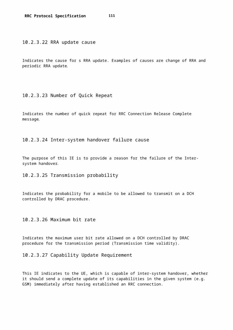
Information Element/Group name
Presence Range IE type and reference
Semantics description
Parameters sent for each transport channel
1 to <maxTrCHcount>
Transport CH ID M Threshold MTime to trigger M Indicates the period of time
between the timing of event detection and the timing of sending Measurement Report.
Pending time after trigger M Indicates the period of time during which it is forbidden to send any new measurement reports with the same measurement ID even if the triggering condition is fulfilled again.
Amount of reporting M Measurement for the indicated Transport CH ID is “released” after the indicated amount of reporting from the UE itself.
FFSReporting interval M Indicates the interval of
periodical report during the event is in the detected state
FFS
Range Bound Explanation
MaxTrCHcount Maximum number of transport channels
10.2.7.28 Quality measurement reporting criteria (FFS)
(Note: Only the section is made.)
10.2.7.29 UE internal measurement reporting criteria
The triggering of the event-triggered reporting for a UE internal measurement. All events concerning UE internal measurements are labelled 6x where x is a, b, c….
Event 6a: The UE Tx power becomes larger than an absolute threshold
Event 6b: The UE Tx power becomes less than an absolute threshold
Event 6c: The UE Tx power reaches its minimum value
Event 6d: The UE Tx power reaches its maximum value
111 RRC Protocol Specification
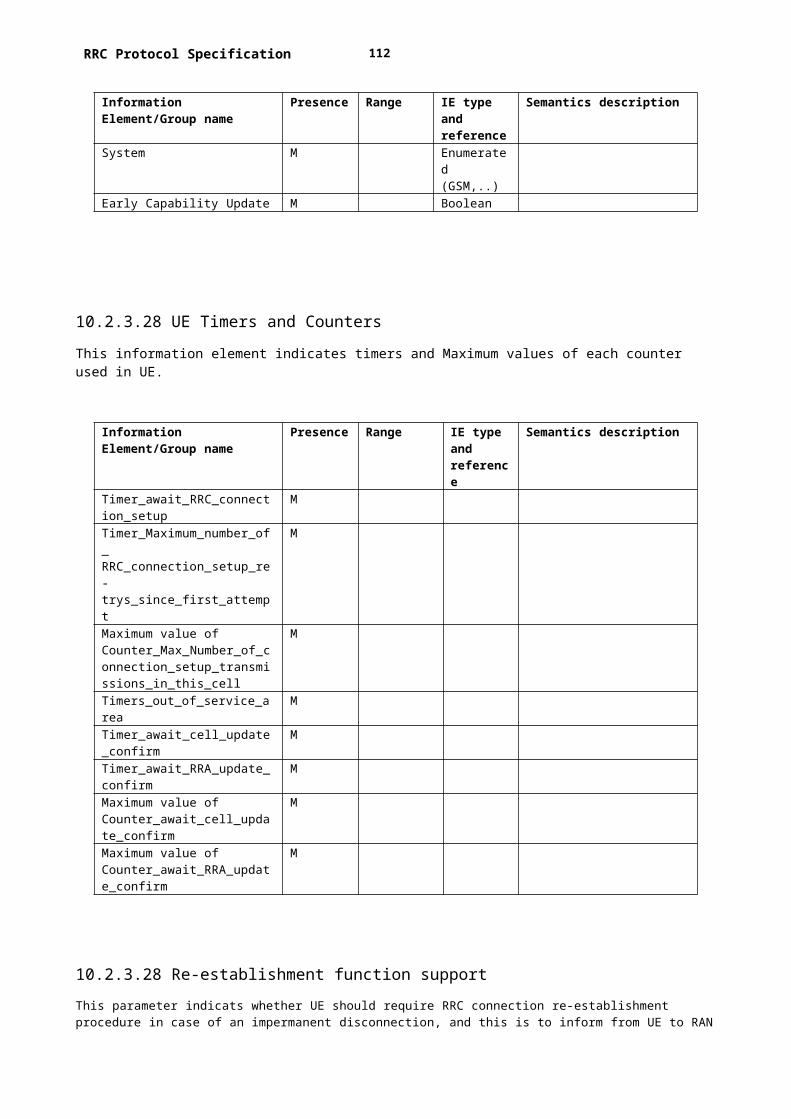
Event 6e: The UE RSSI reaches the UE’s dynamic receiver range
Information Element/Group name
Presence Range IE type and reference
Semantics description
Parameters sent for each UE internal measurement event
1 to <maxEventcount>
Event ID M 6a, 6b, 6c, 6d or 6e Time-to-trigger M Indicates the period of time
between the timing of event detection and the timing of sending Measurement Report.
Tx power threshold C - clause 1
In event 6a, 6b
Parameters REFERENCE TYPE NOTE
For each event Event ID M 6a, 6b, 6c, 6d or 6e
Time-to-trigger M Indicates the period of time between the timing of event detection and the timing of sending Measurement Report.
Tx power threshold C In event 6a, 6b
Condition Explanation
Clause 1 This parameter is only sent in event 6a,6b
10.2.7.30 Periodical reporting criteria
Contains the periodical reporting criteria information. It is necessary only in the periodical reporting mode.
Information Element/Group name
Presence Range IE type and reference
Semantics description
Max number of reporting cells O Indicates the maximum number of cells to report.
Amount of reporting O Measurement is “released” after the indicated amount of reporting from the UE itself
Reporting interval O Indicates the interval of periodical report.
10.2.7.31 Intra-frequency measurement event results
This IE contains the measurement event results that are reported to RAN for intra-frequency measurements.
112 RRC Protocol Specification

Information Element/Group name
Presence Range IE type and reference
Semantics description
Event ID MPrimary CCPCH info M
10.2.7.32 Inter-frequency measurement event results (FFS)
This IE contains the measurement event results that are reported to RAN for inter-frequency measurements.
The further division of this IE into parameters is FFS.
10.2.7.33 Inter-system measurement event results (FFS)
This IE contains the measurement event results that are reported to RAN for inter-system measurements.
The further division of this IE into parameters is FFS.
10.2.7.34 Traffic volume measurement event results
Contains the event result for a traffic volume measurement.
Information Element/Group name
Presence Range IE type and reference
Semantics description
Transport CH ID M
10.2.7.35 Quality measurement event results (FFS)
(Note: Only the section is made.)
10.2.7.36 Measured results
Contains the measured results of the quantity indicated optionally by Reporting Quantity in Measurement Control. "Measured results" can be used for both event trigger mode and periodical reporting mode.
113 RRC Protocol Specification

Information Element/Group name
Presence Range IE type and reference
Semantics description
RB ID + RLC buffers payload
O
PCCPCH Info + Primary CCPCH RX Ec/I0
O
PCCPCH Info + Primary CCPCH RX SIR (RSCP/ISCP)
O FFS
PCCPCH Info + Primary CCPCH RX power (RSCP)
O FFS
PCCPCH Info + Path loss
O FFS
PCCPCH Info + Path loss plus UL load
O FFS
PCCPCH Info + Measured time difference to cell
O
DL Transport CH BLER ODL Transport CH BER O FFSUE Transmission Power OUE Position OCell ID O FFS
10.2.7.37 SFN Measurement Indicator
Indicates whether the UE should read cell SFN of the target neighbour cell or not.
10.2.8 Other Information elements
10.2.8.1 BCCH modification info
Indicates modification of the System Information on BCCH.
Information Element/Group name
Presence Range IE type and reference
Semantics description
BCCH modification type M FFSModification time O FFS
10.2.8.2 Inter-system message
This Information Element contains one or several messages that are structured and coded according to the specification used for the system type indicated by the first parameter.
Information Element/Group name
Presence Range IE type and reference
Semantics description
System type M Enumerated (GSM,..)
Message(s) M Formatted and coded according to specification for the indicated system type.
114 RRC Protocol Specification
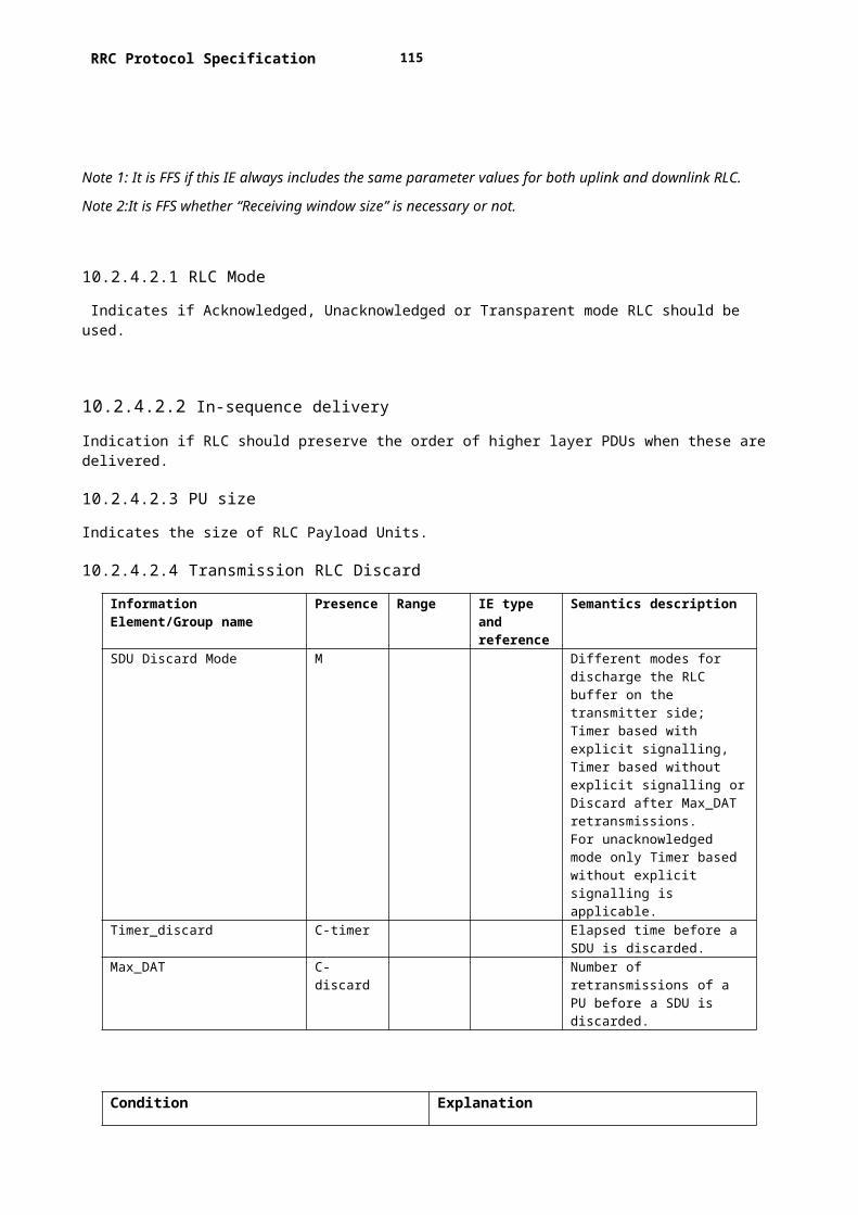
10.2.8.3 COUNT-start
This Information Element indicates the ciphering sequence number at which the new ciphering configuration (e.g. new cipher key) starts to apply. It can be used for both directions.
Parameters REFERENCE TYPE NOTECOUNT-start M
11 Message and Information element abstract syntax (with ASN.1)
This chapter contains definitions for RRC PDUs and IEs using a subset of ASN.1 as specified in I2.01. PDU and IE definitions are grouped into separate ASN.1 modules.
Note that the proposal is to keep both chapter 10 and 11 (at least until all messages and information elements are fully discussed and agreed by CWTS WG1). Chapter 10 is intended to give an abstract description (in English) of the messages and information elements whereas chapter 11 should contain the exact normative definitions with all necessary details.
115 RRC Protocol Specification

12 Message transfer syntaxTransfer syntax for RRC PDUs is derived from their abstract syntax definitions by use of encoding rules.
13 Protocol statesService state diagram(s) of the RRC sublayer. (E.g. like in GSM0407.)
13.1 RRC States and State Transitions including GSM
Figure 3 shows the RRC states in Connected Mode, including transitions between RAN connected mode and GSM connected mode for PSTN/ISDN domain services, and between RAN connected mode and GSM/GPRS packet modes for IP domain services. It also shows the transitions between Idle Mode and RAN Connected Mode and further the transitions within RAN connected Mode.
Figure 3: RRC States and State Transitions including GSM
[1: The indicated division within Idle Mode is only included for clarification and shall not be interpreted as states.]
It shall be noted that not all states may be applicable for all UE connections. For a given QoS requirement on the UE connection, only a subset of the states may be relevant.
116 RRC Protocol Specification
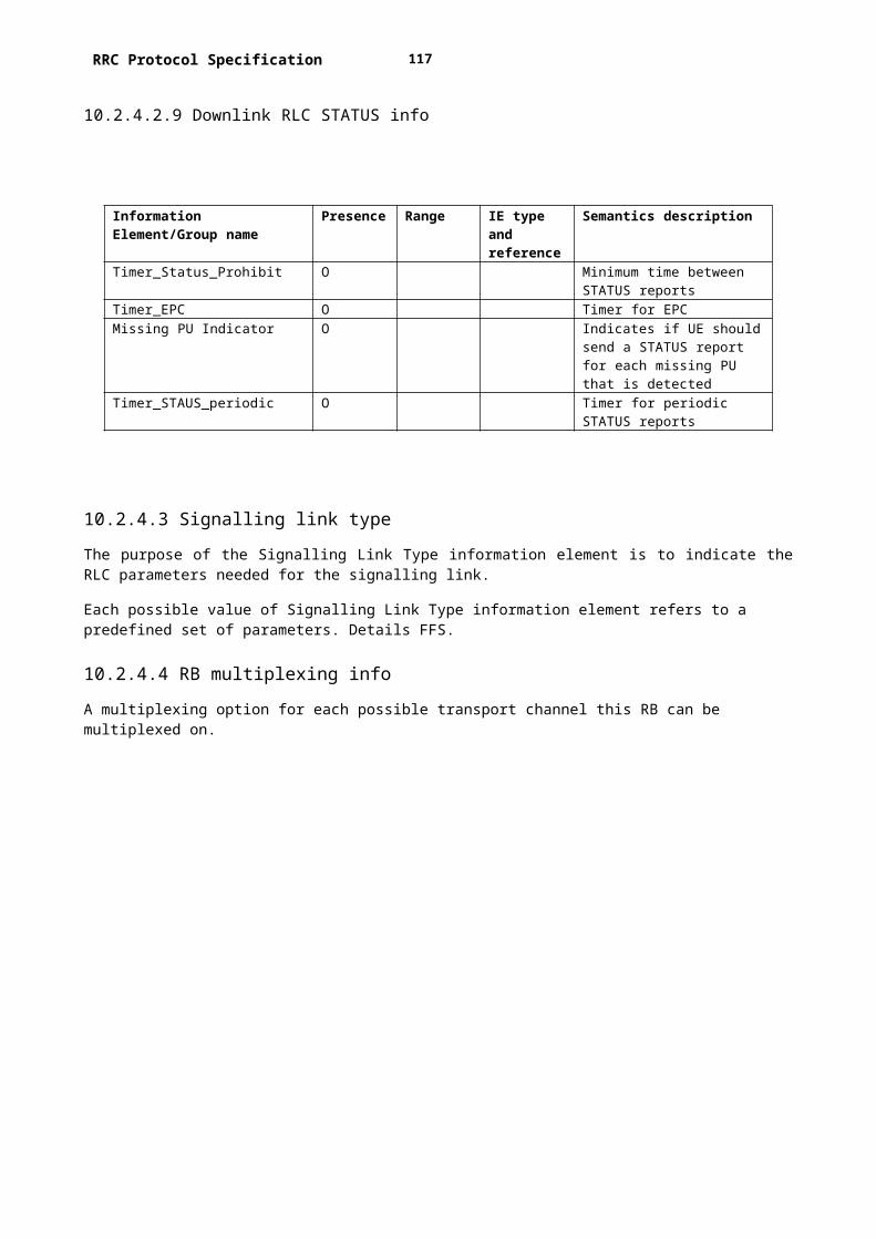
After power on, the UE stays in Idle Mode until it transmits a request to establish an RRC Connection. In Idle Mode the connection of the UE is closed on all layers of the RAN. In Idle Mode the UE is identified by non-access stratum identities such as IMSI, TMSI and P-TMSI. In addition, the RAN has no own information about the individual Idle Mode UE:s, and it can only address e.g. all UE:s in a cell or all UE:s monitoring a paging occasion. The UE behaviour within this mode is described in /4/.
The RAN Connected Mode is entered when the RRC Connection is established. The UE is assigned a radio network temporary identity (RNTI) to be used as UE identity on common transport channels. [Note: The exact definition of RRC connection needs further refinement.] The RRC states within RAN Connected Mode reflect the level of UE connection and which transport channels that can be used by the UE.
For inactive stationary data users the UE may fall back to PCH on both the Cell RRA levels. That is, upon the need for paging, the RAN shall check the current level of connection of the given UE, and decide whether the paging message shall be sent within the RRA, or should it be sent via a specific cell.
13.2 Transition from Idle Mode to RAN Connected ModeThe transition to the RAN Connected Mode from the Idle Mode can only be initiated by the UE by transmitting a request for an RRC Connection. The event is triggered either by a paging request from the network or by a request from upper layers in the UE.
When the UE receives a message from the network that confirms the RRC connection establishment, the UE enters the CELL_FACH or CELL_DCH state of RAN Connected Mode.
In the case of a failure to establish the RRC Connection the UE goes back to Idle Mode. Possible causes are radio link failure, a received reject response from the network or lack of response from the network (timeout).
13.3 RAN Connected Mode States and Transitions
13.3.1 CELL_DCH stateThe CELL_DCH state is characterized by
A dedicated physical channel is allocated to the UE in uplink and downlink.
The UE is known on cell level according to its current active set.
Dedicated transport channels, downlink shared transport channels, and a combination of these transport channels can be used by the UE.
The CELL_DCH-state is entered from the Idle Mode through the setup of an RRC connection, or by establishing a dedicated physical channel from the CELL_FACH state.
A PDSCH may be assigned to the UE in this state, to be used for a DSCH.
These CELL_DCH state is further divided depending on the type of information that is allowed to be transmitted on the dedicated channel(s) and the downlink shared channel. The substates are shown in Figure 4.
117 RRC Protocol Specification

Figure 4: Substates in CELL_DCH state
13.3.1.1 Control only substate
[Editor’s note: The applicability of the control only substate to the TDD-mode is FFS. ]
In Control only substate, the uplink and downlink DCHs are allocated, but no user data frames can be exchanged with the exception of data that uses the signalling connection e.g. SMS. Signalling in this substate includes link maintenance and higher layer signalling.
The Control only substate is provided to save air interface capacity and provide efficient packet transfer capacity allocation.
13.3.1.2 User data active substate
In this substate RAN has allocated transmission resources for the UE and it may transmit data without a prior request up to the peak capacity that is currently granted to that UE.
Some part or all of the DTCH resources can be allocated from the DSCH.
13.3.1.3 Transition from CELL_DCH to Idle Mode
Transition to Idle Mode is realised through the release of the RRC connection.
13.3.1.4 Transition from CELL_DCH to CELL_FACH state
Transition to CELL_FACH state can occur either
a) through the expiration of an inactivity timer (TDCH),
b) at the end of the time period for which the dedicated / shared channel was allocated or
c) via explicit signalling.
13.3.1.5 Radio Resource Allocation tasks (CELL_DCH)
For the DCH, several physical channel allocation strategies may be applied. The allocations can be either permanent (needing a DCH release message) or based on time or amount-of-data.
Resource allocation can be done separately for each packet burst with fast signalling on the DCH. Transition out of the Control only state is either triggered by user capacity allocation or by timeout (no data transaction requests received within a specified time period).
For each radio frame the UE and the network indicate the current data rate (in uplink and downlink respectively) using the transport format combination indicator (TFCI). If the configured set of combinations (i.e. transport format set for one transport channel) are found to be insufficient to retain the QoS requirements for a transport channel, the network initiates a reconfiguration of the transport format set (TFS) for that transport channel. This reconfiguration
118 RRC Protocol Specification

can be done during or in between data transmission. Further, the network can reconfigure the physical channel allowing an increase or decrease of the peak data rate.
For the uplink data transmission, the UE reports the observed traffic volume to the network in order for the network to re-evaluate the current allocation of resources. This report contains e.g. the amount of data to be transmitted or the buffer status in the UE.
If during data transfer the UE is unable to transmit at the requested output power when using the peak allocated capacity, the UE shall reduce transmission rate within the current 10 ms radio frame in order to maintain the closed-loop power control.
13.3.1.6 RRC Connection mobility tasks (CELL_DCH)
Depending on the amount and frequency of data macrodiversity (soft handover) may or may not be applied.
The RRC Connection mobility is handled by measurement reporting, soft handover and hard handover procedures.
13.3.1.7 Localised Service Area (LSA) support
[Editor’s note: A liaison statement to SMG12 has been sent to receive guidance on the functionalities that would need to be defined in RAN to support SoLSA-like (Support of LSA, GSM) services.]
In case of a network-controlled handover procedure, RAN shall take into account the local support of LSA service and the enventual subscription information of the UE to those LSA regarding the provision of service to the UE.
Regarding soft handover, the following principles are applied by RAN:
For "LSA only" UE, the RRC connection shall be maintained by RAN as long as at least one cell of the active set belongs to a UE subscribed LSA.
For "LSA exclusive access" cells, RAN shall prevent such cell from being part of the active set if the UE has not subscribed to the corresponding LSA
Regarding network controlled hard handover, the following principles are applied by RAN:
For "LSA only" UE, RAN shall prevent the UE from being handed over a cell which does not belong to a UE subscribed LSA.
For "LSA exclusive access" cells, RAN shall prevent the UE from being handed over such a cell if the UE has not subscribed to the corresponding LSA
13.3.1.8 UE Measurements (CELL_DCH)
The UE shall perform measurements and transmit measurement reports according to the measurement control information.
The UE shall use the connected mode measurement control information received in other states until new measurement control information has been assigned to the UE.
13.3.1.9 Transfer and update of system information (CELL_DCH)
UEs with certain capabilities shall read system information broadcast on FACH. [Editors note: Currently it is only UEs having DRAC capabilities that need to read system information on FACH.]
13.3.2 CELL_FACH stateThe CELL_FACH state is characterised by:
No dedicated physical channel is allocated to the UE.
The UE continuously monitors a FACH in the downlink
The UE is assigned a default common or shared transport channel in the uplink (e.g. RACH) that it can use
119 RRC Protocol Specification
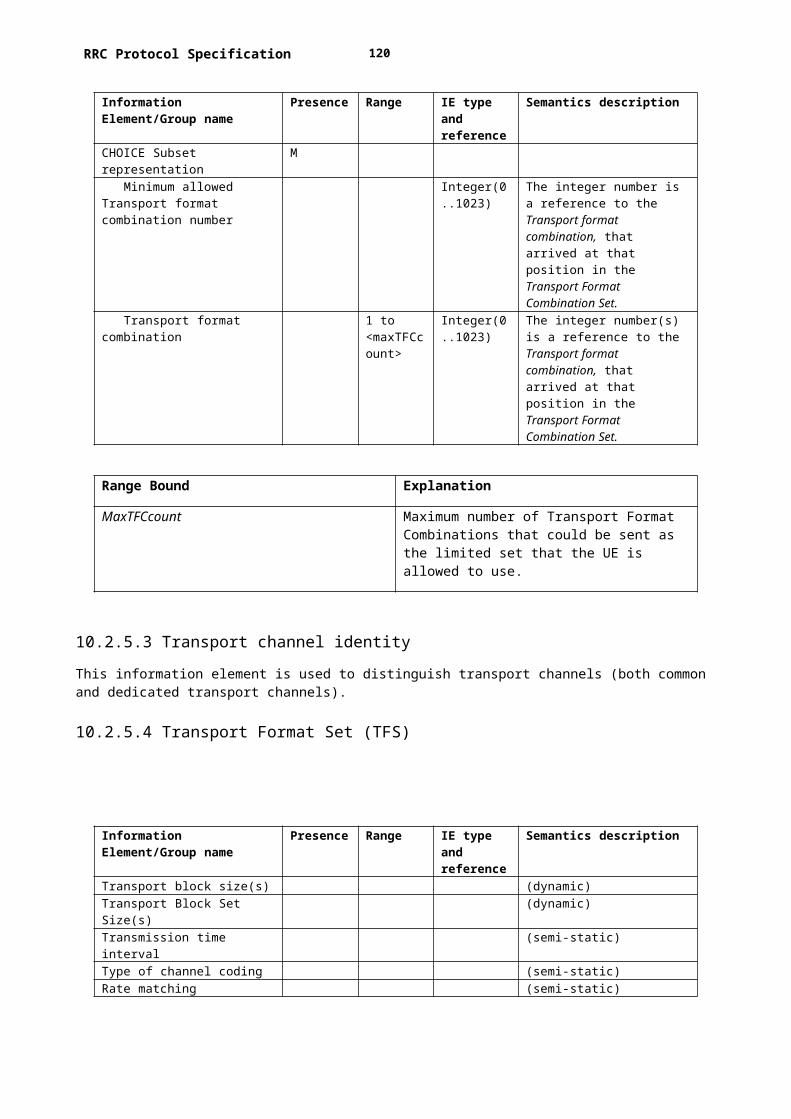
anytime according to the access procedure for that transport channel
The position of the UE is known by RAN on cell level according to the cell where the UE last made a cell update.
In the CELL_FACH substate the UE shall perform the following actions:
listens to an FACH
listens to the BCH transport channel of the serving cell for the decoding of system information messages
initiates a cell update procedure on cell change of another cell
Use C-RNTI assigned in the current cell as the UE identity on common transport channels unless when a new cell is selected
transmits uplink control signals and small data packets on the RACH.
transmits uplink control signals and larger data packets on USCH when resources are allocated to cell and UE is assigned use of those CPCH resources.
Furthermore, the UE may use the FAUSCH to trigger the allocation of a new DCH by RAN. Further rate adaptation can be done via the DCCH of the new DCH.
13.3.2.1 Transition from CELL_FACH to CELL_DCH state
A transition occurs, when a dedicated physical channel is established via explicit signalling.
The state transition may also be done by using the FAUSCH.
13.3.2.2 Transition from CELL_FACH to CELL_PCH state
Since the UE performs continuous reception of FACH in this state, it should be moved to the CELL_PCH state if the data service has not been active for a while. When an inactivity timer (T rf) expires, the UE state is changed to CELL_PCH in order to decrease power consumption. Also, when coming from CELL_PCH state, and after the cell update procedure has been performed, the UE state is changed back to CELL_PCH state if neither the UE nor the network has any data to transmit.
When coming from the CELL_FACH substate, the FAUSCH is still available in the CELL_PCH state after the transition.
13.3.2.3 Transition from CELL_FACH to Idle Mode
The release of the RRC connection moves the UE to the idle mode.
13.3.2.4 Transition from CELL_FACH to RRA_PCH State
To perform the RRA update procedure, UE is moved temporarily from RRA_PCH to CELL_ FACH state. After the RRA update is completed, UE state is changed back to RRA _PCH.
If FAUSCH is intended to be used in RRA_PCH State, a FAUSCH transport channel needs to be allocated for the intended cells in the RRA prior to this transition.
13.3.2.5 Radio Resource Allocation Tasks (CELL_FACH)
In the CELL_ FACH state the UE will monitor an FACH. It is enabled to transmit uplink control signals and it may be able to transmit small data packets on the RACH. The network can assign the UE transport channel parameters (e.g. transport format sets) in advance, to be used when a DCH is used. When the physical channel for DCH is assigned, the UE state is changed to CELL_DCH and the assigned TFS for the DCH can be used.
120 RRC Protocol Specification

The UE shall use the common physical channel and transport channel configuration according to the system information when no UE dedicated physical channel or transport channel channel configuration has been assigned.
For the uplink data transmission, the UE reports the observed traffic volume to the network in order for the network to re-evaluate the current allocation of resources. This report contains e.g. the amount of data to be transmitted or the buffer status in the UE.
When there is either user or control data to transmit, a selection procedure determines whether the data should be transmitted on a common transport channel, or if a transition to CELL_DCH should be executed. The selection is dynamic and depends on e.g. traffic parameters (amount of data, packet burst frequency).
The RAN can assign USCH/DSCH resources to the UE in CELL_FACH state. When DSCH/USCH resources are assigned, the UE will continue to monitor FACHs. The UE may use the RACH to transmit uplink control signals and small data packets. The UE also may choose to transmit data packets, larger than those carried on the RACH, on the DSCH/USCH channel. The UE selects either the RACH or one of the DSCH/USCH channels to make maximum use of the capacity available on that channel.
The UE provides the RAN with USCH/DSCH measurement data which includes data queue depth (current size of data buffers), average access time for each USCH/DSCH channel used, and average traffic volume on each USCH/DSCH channel used. With these measurands and the RAN MAC-d measurement reports, the RAN can reallocate network resources on a periodic basis. The RAN allocates USCH/DSCH Sets to each cell and assigns UEs to one of the cell’s USCH/DSCH Sets. The UEs can dynamically access the USCH/DSCH resources without further RAN control.
13.3.2.6 RRC Connection mobility tasks (CELL_FACH)
In this state the location of the UE is known on cell level. A cell update procedure is used to report to the RAN, when the UE selects a new cell to observe the common downlink channels of a new cell. Downlink data transmission on the FACH can be started without prior paging.
In CELL_FACH state an CELL_ FACH cell set comparable to the active set of a dedicated channel in HO is maintained both in the UE and in the network. The CELL_ FACH cell set representes a list of cells which have the potential to serve the UE from radio signal strength perspective. The UE performs measurements and reporting for the CELL_ FACH cell set using the same procedures as in CELL_DCH state. The thresholds required for triggering a measurement report may be different from those in CELL_DCH state.
The CELL_FACH cell set information is used by the network to decide whether the user data can be routed directly via a cell to a specific UE or soft handover would be required when resuming the DCH operation. In addition, the CELL_FACH cell set information provides the means for the network to evaluate potential interference conditions and select a suitable amount of capacity when moving the UE in the DCH active substate, for both uplink and downlink data transfer.
The UE monitors the broadcast channel and system information on BCCH of its own and neighbour cells and from this the need for the updating of cell location is identified.
The UE shall perform cell reselection and upon selecting a new UTRA cell, it shall initiate a cell update procedure. Upon selecting a new cell belonging to another radio access system than UTRA, the UE shall enter idle mode and make an access to that system according to its specifications.
13.3.2.7 UE Measurements (CELL_FACH)
The UE shall perform measurements and transmit measurement reports according to the measurement control information.
The UE shall use the measurement control information according to the system information when no UE dedicated measurement control information has been assigned.
121 RRC Protocol Specification

13.3.2.8 Transfer and update of system information (CELL_FACH)
The UE shall read the BCH to acquire valid system information. For each acquisition, the UE may need different combinations of system information broadcast on BCH. The scheduling on the broadcast channel is done in such way that the UE knows when the requested information can be found.
When the system information is modified, the scheduling information is updated to reflect the changes in system information transmitted on BCH. The new scheduling information is broadcast on FACH in order to inform UEs about the changes. If the changes are applicable for the UE, the modified system information is read on BCH.
13.3.3 CELL_PCH stateThe CELL_PCH state is characterised by:
No dedicated physical channel is allocated to the UE
No uplink activity is possible.
The position of the UE is known by RAN on cell level according to the cell where the UE last made a cell update in CELL_FACH state.
In this state the UE performs the following actions:
monitor the paging occasions according to the DRX cycle and receive paging information on the PCH
listens to the BCH transport channel of the serving cell for the decoding of system information messages
initiates a cell update procedure on cell change.
The DCCH logical channel cannot be used in this sub. If the network wants to initiate any activity, it needs to make a paging request on the PCCH logical channel in the known cell to initiate any downlink activity.
13.3.3.1 Transition from CELL_PCH to RRA_PCH State
The only overhead in keeping a UE in the CELL_PCH state is the potential possibility of cell updating, when the UE moves to other cells.
To reduce this overhead, the UE is moved to the RRA_PCH State when low activity is observed. This can be controlled with an inactivity timer, and optionally, with a counter, which counts the number of cell updates. When the number of cell updates has exceeded certain limits (a network parameter), then RAN orders the UE to the RRA_PCH State. This transition is made via the CELL_FACH state.
13.3.3.2 Transition from CELL_PCH to CELL_FACH state
The UE is transferred to >CELL_FACH state either by a command (packet paging) from RAN or through any uplink access.
If a valid FAUSCH transport channel is allocated for the current cell, the UE changes to CELL_FACH state as soon as it uses the FAUSCH to allocate a DCH.
13.3.3.3 Radio Resource Allocation Tasks (CELL_PCH)
In CELL_PCH state no resources have been granted for data transmission. For this purpose, a transition to another state has to be executed.
The UE may use Discontinuous Reception (DRX) in order to reduce power consumption. When DRX is used the UE needs only to receive at one paging occasion per DRX cycle. The UE may be instructed to use a specific DRX cycle
122 RRC Protocol Specification
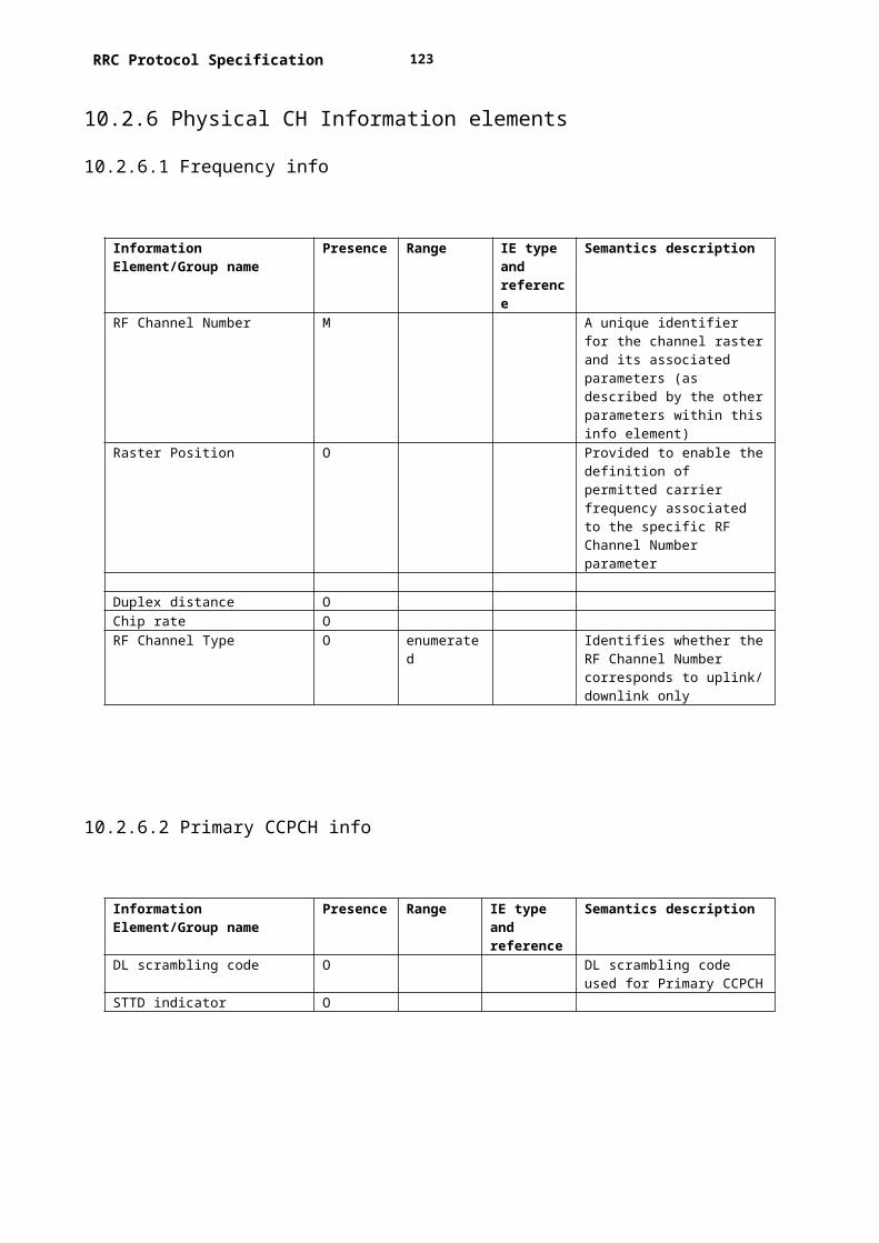
length by the network. The UE shall determine its paging occasions in the same way as for Idle Mode, see TS 25.304.
13.3.3.4 RRC Connection mobility tasks (CELL_PCH)
In the CELL_PCH state, the UE mobility is performed through cell reselection procedures, which may differ from the one defined in TS 25.304.
The UE shall perform cell reselection and upon selecting a new UTRA cell, it shall move to CELL_FACH state and initiate a cell update procedure in the new cell. After the cell update procedure has been performed, the UE shall change its state back to CELL_PCH state if neither the UE nor the network has any more data to transmit.
Upon selecting a new cell belonging to another radio access system than TD-SCDMA, the UE shall enter idle mode and make an access to that system according to its specifications.
13.3.3.5 UE Measurements (CELL_PCH)
The UE shall perform measurements and transmit measurement reports according to the measurement control information.
The UE shall use the measurement control information according to the system information when no UE dedicated measurement control information has been assigned.
13.3.3.6 Transfer and update of system information (CELL_PCH)
The UE shall read the BCH to acquire valid system information. For each acquisition, the UE may need different combinations of system information broadcast on BCH. The scheduling on the broadcast channel is done in such way that the UE knows when the requested information can be found.
13.3.4 RRA_PCH StateThe RRA_PCH state is characterised by:
Neither an uplink nor a downlink dedicated physical channel is allocated to the UE
No uplink activity is possible
The location of the UE is known on RAN Registration area level according to the RRA assigned to the UE during the last RRA update in CELL_FACH state.
In this state the UE performs the following actions:
monitor the paging occasions according to the DRX cycle and receive paging information on the PCH
listens to the BCH transport channel of the serving cell for the decoding of system information messages
initiates a RRA updating procedure on RRA change.
The DCCH logical channel cannot be used in this state. If the network wants to initiate any activity, it needs to make a paging request on the PCCH logical channel within the RRA where the location of the UE is known. If the UE needs to transmit anything to the network, it goes to the CELL_FACH state.
The transition to RRA_PCH State can be controlled with an inactivity timer, and optionally, with a counter which counts the number of cell updates. When the number of cell updates has exceeded certain limits (a network parameter), then the UE changes to the RRA_PCH State.
RRA updating is initiated by the UE which, upon the detection of the Registration area, sends the network the Registration area update information on the RACH of the new cell.
13.3.4.1 Transition from RRA_PCH State to Cell_FACH State
Any activity causes the UE to be transferred to CELL_ FACH State. Uplink access is performed by either RACH.
123 RRC Protocol Specification
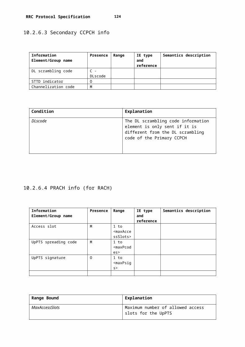
Note that the release of an RRC connection is not possible in the RRA_PCH State. The UE will first move to Cell_FACH State to perform the release signalling.
13.3.4.2 Radio Resource Allocation Tasks (RRA _PCH)
In RRAPCH State no resources have been granted for data transmission. For this purpose, a transition to CellFACH State has to be executed.
The UE may use Discontinuous Reception (DRX) in order to reduce power consumption. When DRX is used the UE needs only to receive at one paging occasion per DRX cycle. The UE may be instructed to use a specific DRX cycle length by the network. The UE shall determine its paging occasions in the same way as for Idle Mode, see TS 25.304.
13.3.4.3 RRC Connection mobility tasks (RRA_PCH)
In RRA_PCH State the location of a UE is known on RAN Registration area level.
In this state, the UE mobility is performed through RRA reselection procedures, which may differ from the definitions in S2.04. The UE shall perform cell reselection and upon selecting a new cell belonging to an RRA which does not match the RRA used by the UE, the UE shall move to CELL_FACH state and initiates a RRA update towards the network. After the RRA update procedure has been performed, the UE shall change its state back to RRA_PCH state if neither the UE nor the network has any more data to transmit.
Upon selecting a new cell belonging to another radio access system than UTRA, the UE shall enter idle mode and make an access to that system according to its specifications (FFS).
13.3.4.4 UE Measurements
The UE shall perform measurements and transmit measurement reports according to the measurement control information.
The UE shall use the measurement control information according to the system information when no UE dedicated measurement control information has been assigned.
13.3.4.5 Transfer and update of system information (RRA_PCH)
The same mechanisms to transfer and update system information as for state CELL_PCH are applicable for UEs in RRA_PCH state, see section .
13.4 Inter-system handover with PSTN/ISDN domain servicesWhen using PSTN / ISDN domain services, RAN is using an Inter-System Handover Procedure and GSM is using a Handover procedure for the transition from RAN Connected Mode to GSM Connected Mode.
13.5 Inter-system handover with IP domain servicesWhen using IP domain services, the UE initiates cell reselection from a GSM/GPRS cell to a RAN cell and then uses the RRC Connection Establishment procedure for the transition to RAN Connected mode.
When the RRC Connection is established from Idle Mode (GPRS Packet Idle Mode) the RRC CONNECTION REQUEST message contains an indication, that RAN needs to continue an already established GPRS UE context from the CN. This indication allows RAN to e.g. prioritize the RRC CONNECTION REQUEST from the UE.
In RAN connected mode RAN is using UE or network initiated cell reselection to change from a RAN cell to a GSM/GPRS cell. If the cell reselection was successful the UE enters Idle Mode (GPRS Packet Idle Mode). The UE sends a packet channel request from Idle Mode (GPRS Packet Idle mode) to establish a Temporary Block flow and enter GPRS Packet Transfer Mode. In the GPRS Packet Transfer Mode the UE sends a RA Update request message. The RA Update Request message sent from the UE contains an indication that GSM/GPRS need to continue an already established RAN UE context from the CN. This means that the RA Update request is always sent for the transition from RAN Connected Mode to GSM/GPRS regardless if the RA is changed or not.
124 RRC Protocol Specification

[Note: The reason for using RA update instead of a new message is to reduce the impact on the existing GSM/GPRS specification.]
13.6 Inter-system handover with simultaneous IP and PSTN/ISDN domain services[Note: This is an initial assumption that needs to be seen by SMG2 and requiring checking by SMG2, when the work on this item has progressed.]
13.6.1 Inter-system handover RAN to GSM / BSSFor a UE in CELL_DCH state using both PSTN / ISDN and IP Domain services the Inter-system handover procedure is based on measurement reports from the UE but initiated from RAN.
The UE performs the Inter-system handover from RAN Connected Mode to GSM Connected Mode first. When the UE has sent handover complete message to GSM / BSS the UE initiates a temporary block flow towards GPRS and sends a RA update request.
If the Inter-system handover from RAN Connected Mode to GSM Connected Mode was successful the handover is considered as successful regardless if the UE was able to establish a temporary block flow or not towards GPRS.
In case of Inter-system handover failure the UE has the possibility to go back to RAN Connected Mode and re-establish the connection in the state it originated from without attempting to establish a temporary block flow. If the UE has the option to try to establish a temporary block flow towards GSM / GPRS after Inter-system handover failure is FFS.
13.6.2 Inter-system handover GSM / BSS to RANFor a UE in GSM Connected Mode using both PSTN / ISDN and IP domain services the Inter-system handover procedure is based on measurement reports from the UE but initiated from GSM / BSS.
The UE performs the Inter-system handover from GSM Connected Mode to RAN Connected Mode.
In RAN Connected Mode both services are established in parallel.
If the Inter-System handover from GSM Connected mode to RAN Connected Mode was successful the handover is considered as successful.
In case of Inter-system handover failure the UE has the possibility to go back to GSM Connected Mode and re-establish the connection in the state it originated from.
14 Protocol timers, counters and other parametersDescription of timers and counters and possible other parameters related to RRC procedures.
125 RRC Protocol Specification
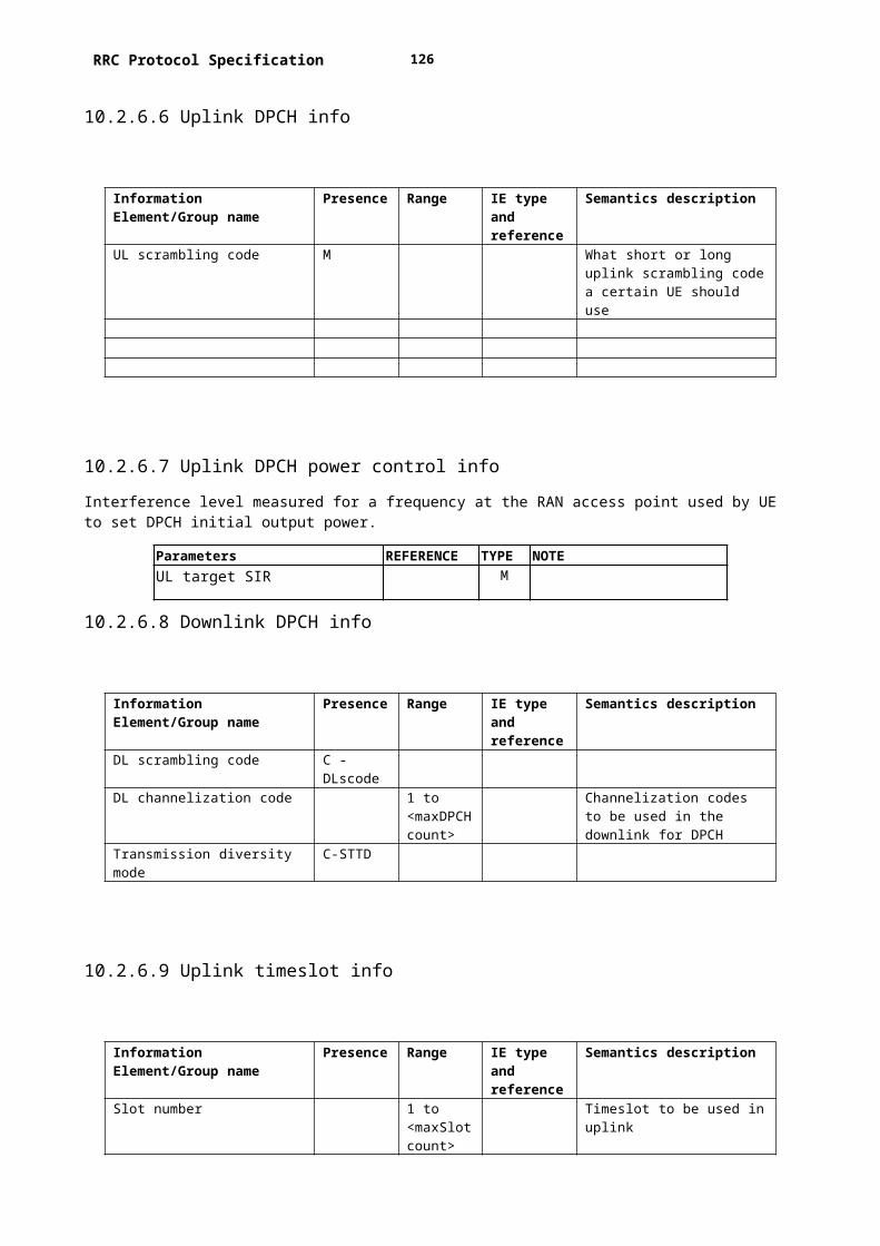
14.1 Timer for RACH/FACH or PCH substate
14.1.1 DescriptionSince there is no signal (such as DCH/DCH substate) for RAN to confirm the status of the UE which is located out
of the service area in RACH/FACH or PCH substate, there is a need to have some mechanism to support this in case of RACH/FACH or PCH by using timers.
There is a need for a timer to start when the UE is located in the out of service area. There are 3 alternatives when to start the timer.
Timer starts when the UE enters the location where it is out of service. The timer stops when the UE enters the service area.
Timer starts only at the timing the UE wants to send data when the UE is located at out of service area. The timer stops when the UE enters the service area.
Timer starts only at the timing the UE wants to send Cell/RRA Update message triggered by expiry of the Periodical Cell/RRA Update timer when the UE is located at out of service area. The timer stops when the UE enters the service area.
14.1.2 TIMERS for UETimer Start Stop At expiry
Timers_out_of_service_area Only the timing when Timer_Periodical_cell/RRA_Update expired
When the service area detected (Action 1)
Transits to IDLE mode(Action 2)
(Action 1) The UE initiates Cell/RRA Update procedure.
(Action 2) Connection failure is indicated to the NAS
14.2 Timers for RRC Connection Setup Procedure
14.2.1 Description
14.2.1.1 RRC Connection Request message
In the RRC Connection Setup procedure, the UE sends RRC Connection Request message and waits for RRC Connection Setup message. If the UE doesn’t receive RRC Connection Setup message, the UE will retransmit the RRC Connection Request message to the RAN (with the latest information). When the UE moves and detects other cell during at the period the UE is waiting for the RRC Connection Setup message, the UE will send RRC Connection Request message at the new cell.
The following timers and counter are needed.
Timer_await_RRC_connection_setup Counter_await_RRC_connection_setup Timer_RRC_connection_establish
The timer (Timer_RRC_connection_establish) is necessary to guarantee the service quality of the period of time from the time when the AS is requested of the RRC Connection from NAS and the time when the AS send the confirmation of the RRC Connection establishment to NAS.
When the UE requested from the NAS to establish RRC connection, the UE sets Timer_await_RRC_connection_setup and Counter_await_RRC_connection_setup. If the UE detects a new cell, the UE sets a new Timer_await_RRC_connection_setup and a new Counter_await_RRC_connection_setup. If the UE requested to wait for “wait time”, the UE waits at least the time sated in the IE ”wait time” and retries with increasing Counter_await_RRC_connection_setup by 1.
When the UE requested from the NAS to establish RRC connection, the UE sets Timer_RRC_connection_establish.
126 RRC Protocol Specification
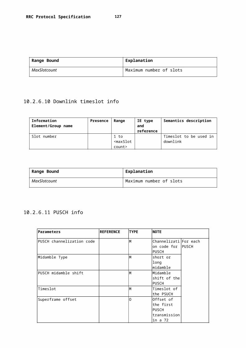
14.2.1.2 RRC Connection Setup message
In the RRC Connection Setup procedure, the RAN sends RRC Connection Setup message and waits for RRC Connection Setup Complete message. If the RAN doesn’t receive RRC Connection Setup Complete message, the RAN will wait for a new RRC Connection Request message from the UE, which moves and detects other cell and sends RRC Connection Request message at the new cell.
The following timer is needed.
Timer_await_RRC_connection_setup_complete
When the RAN receives a RRC Connection Request message, the RAN sets Timer_await_RRC_connection_setup_complete. When a new RRC Connection Request message is received by the RAN, the RAN sets a new Timer_await_RRC_connection_setup_complete.
14.2.2 TIMERS for UE Timer Start Stop At expiry
Timer_await_RRC_connection_setup When RRC Connection Request is sent in case Counter_await_RRC_connection_setup established or incremented
When RRC Connection Setup is received (Action 1)
When RRC Connection Reject is received (Action 2)
Increase Counter_await_RRC_connection_setup
Timer_RRC_connection_establish When the AS in UE requested to establish RRC Connection from the NAS
When RRC Connection is established (Action 3)
When RRC Connection is failed (Action 4)
Enter IDLE mode(Action 4)
(Action 1) Send RRC Connection Setup Complete message.(Action 2) Wait at least the time stated in the IE "wait time" and reties with increasing Counter_await_RRC_connection_setup by 1.(Action 3) Connection establishment is indicated to the NAS.(Action 4) Connection failure is indicated to the NAS.
14.2.3 COUNTER for UETimer Reset Increment Reach max value
Counter_await_RRC_connection_setup When initiates RRC connection procedure in case Timer_RRC_connection_establish established or in case the UE detects a new cell while Timer_RRC_connection_establish is running.
Timer expires Enter IDLE modeStop Timer_RRC_connection_establish
14.2 .4TIMER for RAN (REFERENCE)Timer Start Stop At expiry
Timer_await_RRC_connection_setup_complete
When RRC Connection Setup is sent
When RRC Connection Setup Complete is received
Release UE entity(Action 1)
(Action 1) Connection failure is indicated to the NAS.Note1: RAN establishes Timer_await_RRC_connection_setup_complete when the RAN receives a RRC Connection Setup.
Note2: RAN newly establishes Timer_await_RRC_connection_setup_complete when the RAN receives a RRC Connection Setup during old Timer_await_RRC_connection_setup_complete is running.14.3 Timer for
Periodical Cell Update Procedure
14.3.1DescriptionWhen the UE is in the RACH/FACH substate or in the PCH substate in Cell Connected State, there is no continuous physical
127 RRC Protocol Specification
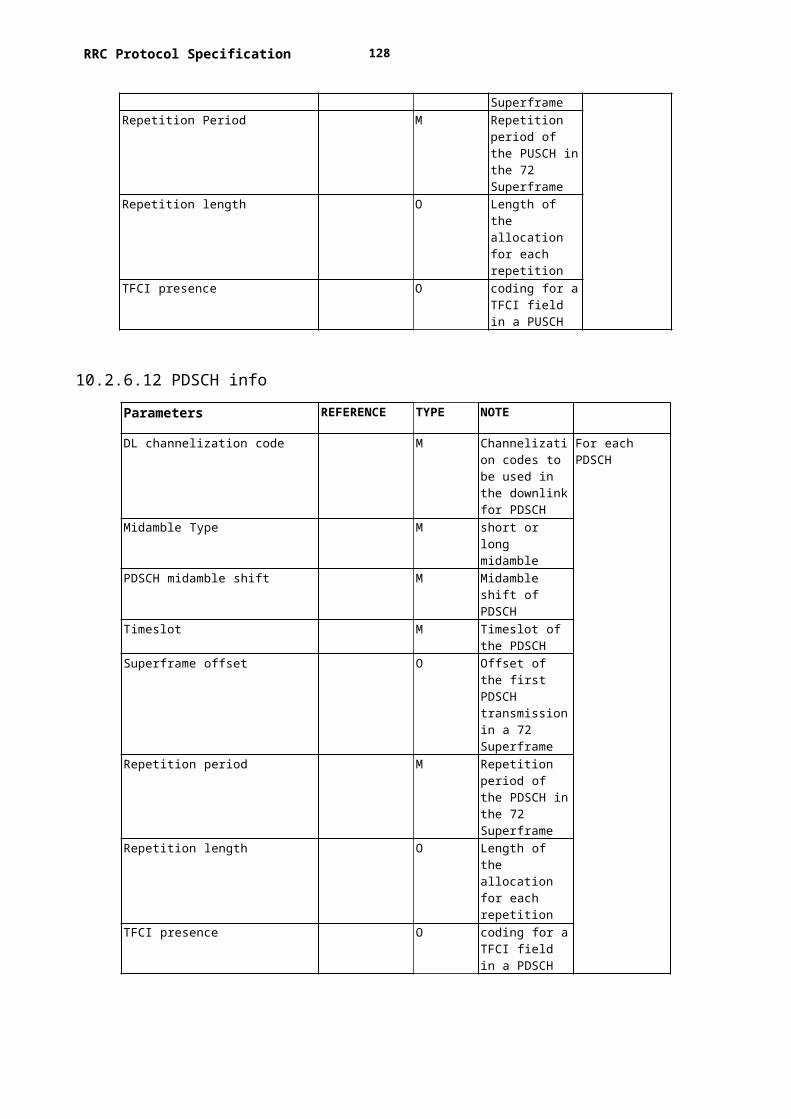
layer support ) to confirm whether the UE is out of service area (out of sync.) or not. In the following situations, when there is no user data or signalling data to receive, RAN cannot know the status of the UE.(1) When the UE moves out of the service area and does not return to the service area.
(2) When the UE loses its battery or when the battery is detached from the UE.
(3) When the UE is turned off at the area which is out the service area.
In order the RAN to keep the same status with the UE, the UE needs to initiate Cell Update procedure periodically. When this mechanism is adopted, it is possible to change the state of the RAN to IDLE mode if there was no access from the UE for a certain period of time. On the other hand, the UE can transit to IDLE mode if the Cell Update procedure fails.
The following timers are needed.
T_periodical_cell_update (UE) T_periodical_RRA_update(UE) T_wait_periodical_cell_update (RAN)
The UE establishes T_periodical_cell_update when the UE enters Cell connected RACH/FACH substate. The UE establishes T_periodical_RRA_update when the UE enters RRA connected PCH substate.The RAN establishes T_wait_periodical_cell_update when the RAN enters Cell connected RACH/FACH substate.
14.3.2 TIMERS for UETimer Start Stop At expiry
T_periodical_cell_update (Note1) When Cell Update Confirm is received
When the UE enters other state or substate
Send Cell Update message to the RAN.
T_periodical_RRA_update (Note2) When RRA Update Confirm is received
When the UE enters other state or substate
Send RRA Update message to the RAN.
Note1: UE establishes T_periodical_cell_update when the UE enters Cell connected RACH/FACH or PCH substate.Note2: UE establishes T_periodical_RRA_update when the UE enters RRA connected PCH substate.
14.3.3 TIMERS for RAN (REFERENCE)Timer Start Stop At expiry
T_wait_periodical_cell_update(Note1, Note2)
When RLC ACK of the Cell Update Confirm is received
When the RAN enters other state or substate
Release UE entity(Action 1)
T_wait_periodical_RRA_update(Note3, Note4)
When RLC ACK of the RRA Update Confirm is received
When the RAN enters other state or substate
Release UE entity(Action 1)
(Action 1) Connection failure is indicated to the NAS.Note1: RAN establishes T_wait_periodical_cell_update when the RAN enters Cell connected RACH/FACH or PCH substate.Note2: T_wait_periodical_cell_update should be larger than T_periodical_cell_update in order to receive the access from UE before the T_wait_periodical_cell_update expires. Note3: RAN establishes T_wait_periodical_RRA_update when the RAN enters RRA connected PCH substate.
Note4: T_wait_periodical_RRA_update should be larger than T_periodical_RRA_update in order to receive the access from UE before the T_wait_periodical_RRA_update expires. 14.4 Timer for Cell Update Procedure
14.4.1Description
14.4.1.1 Cell Update messageIn the Cell Update procedure, the UE sends Cell Update message and waits for Cell Update Confirm message. If the UE doesn’t receive Cell Update Confirm message, the UE will retransmit the Cell Update message (with latest contents) to the RAN. When the UE moves and detects other cell during at the period the UE is waiting for the Cell Update Confirm message, the UE will send Cell Update message at the new cell.
The following timer and counter are needed.
Timer_await_cell_update_confirm Counter_await_cell_update_confirm
128 RRC Protocol Specification
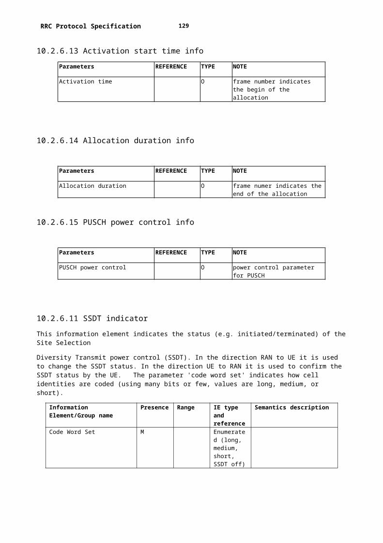
When the UE detects a new cell, the UE sets Timer_await_cell_update_confirm and Counter_await_cell_update_confirm and resets the counter. When the UE is triggered to initiate Cell Update procedure by the expiry of the Timer_periodical_cell_update and the UE is located in the service area, the UE sets Timer_await_cell_update_confirm and Counter_await_cell_update_confirm.
14.4.1.2 Cell Update Confirm messageIn the Cell Update procedure, the RAN sends Cell Update Confirm message and waits for RNTI Reallocation Complete message if needed. If the RAN doesn’t receive RNTI Reallocation Complete message, the RAN will wait for a new Cell Update message from the UE, which moves and detects other cell and sends Cell Update message at the new cell. Therefore counter is not needed.
The following timer is needed.
Timer_await_RNTI_reallocation_complete
When the RAN receives a Cell Update message, the RAN sets Timer_await_RNTI_reallocation_complete if needed (depend of allocation of the SRNC ID and SRNTI). When a new Cell Update message is received by the RAN, Timer_await_RNTI_reallocation_complete is newly established if needed.
14.4.2 TIMERS for UE Timer Start Stop At expiry
Timer_await_cell_update_confirm When Counter_await_cell_update_confirm established or incremented
When Cell Update Confirm is received (Action 1)
When Cell Update Reject (ffs) is received (Action 2)
Increase Counter_await_cell_update_confirm
Timer_await_RRA_update_confirm When Counter_await_RRA_update_confirm established or incremented
When RRA Update Confirm is received (Action 3)
When RRA Update Reject (ffs) is received (Action 4)
Increase Counter_await_RRA_update_confirm
(Action 1) Send RNTI Re-allocation Complete message if there are new SRNC ID and SRNTI allocated.(Action 2) Search for other cell if it is indicated in the Cell Update Reject message (ffs).(Action 3) Send RRA Update Complete message.(Action 4) Search for other cell if it is indicated in the RRA Update Reject message (ffs).
14.3 COUNTER for UECOUNTER Reset Increment Reach max value
Counter_await_cell_update_confirm When initiates cell update procedure in case the UE detects a new cell or triggered by the expiry of Timer_periodical_cell_update
Timer expires Enter IDLE mode(Action 1)
Counter_await_RRA_update_confirm When initiates RRA update procedure in case the UE detects a new RRA or triggered by the expiry of Timer_periodical_RRA_update
Timer expires Enter IDLE mode(Action 1)
(Action 1) Connection failure is indicated to the NAS.
14.4 TIMER for RAN (REFERENCE)Timer Start Stop At expiry
Timer_await_RNTI_reallocation_complete (Note1, 2)
When Cell Update Confirm is sent with new SRNC ID and S-RNTI.
When RNTI Reallocation Complete is received
Release UE entity(Action 1)
Timer_await_RRA_update_complete(Note3, 4)
When RRA Update Confirm is sent
When RRA Update Complete is received
Release UE entity(Action 1)
(Action 1) Connection failure is indicated to the NAS.
129 RRC Protocol Specification
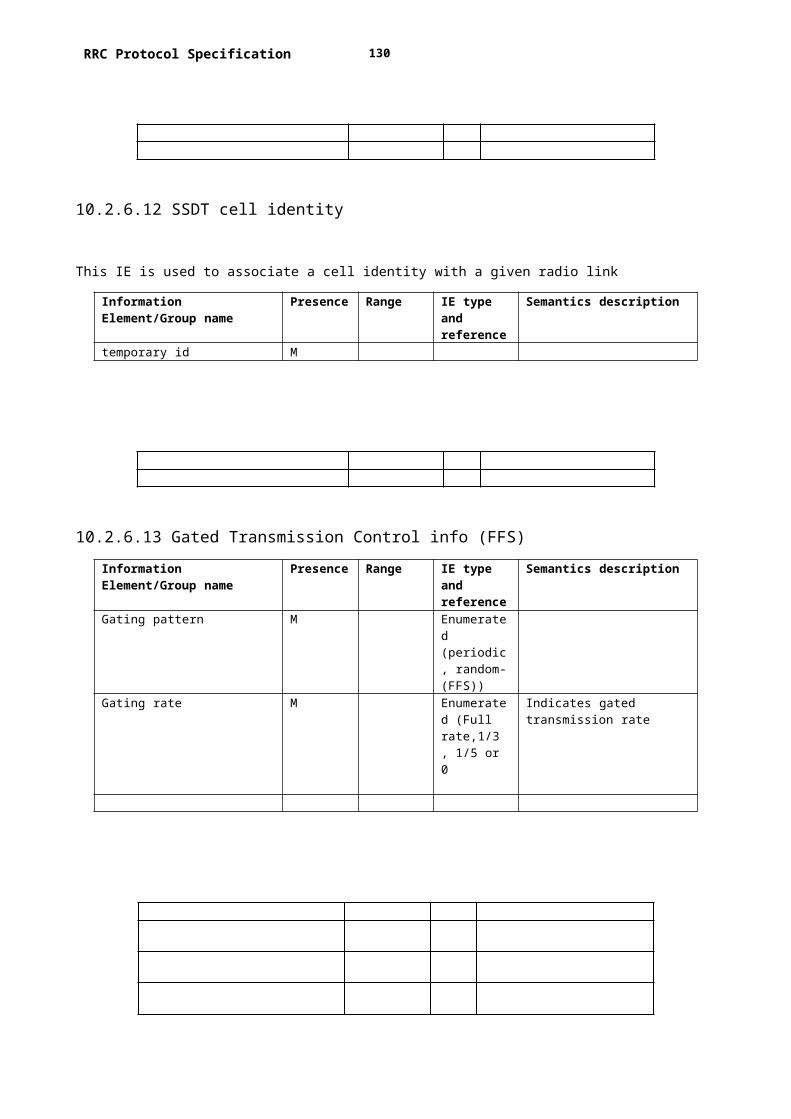
Note1: RAN establishes Timer_await_RNTI_reallocation_complete if needed (depend of allocation of the SRNC ID and SRNTI) when the RAN receives a Cell Update message.Note2: RAN newly establishes Timer_await_RNTI_reallocation_complete if needed when a new Cell Update message is received by the RAN while old Timer_await_RNTI_reallocation_complete is running.Note3: RAN establishes Timer_await_ RRA_update_complete when the RAN receives a RRA Update message.Note4: RAN newly establishes Timer_await_ RRA_update_complete when a new RRA Update message is received by the RAN while old Timer_await_ RRA_update_complete is running.
14.1 TIMERS for UE
Timer Start Stop At expiryTimers_out_of_service_area Only the timing when
Timer_Periodical_cell/RRA_Update expired
When the service area detected (Action 1)
Transits to IDLE mode(Action 2)
(Action 1) The UE initiates Cell/RRA Update procedure.
(Action 2) Connection failure is indicated to the NAS
Timer Start Stop At expiryTimer_await_RRC_connection_setup When RRC Connection
Request is sent in case Counter_Max_Number_of_connection_setup_transmissions_in_this_cell established or incremented
When RRC Connection Setup is received (Action 1)
When RRC Connection Reject is received (Action 2)
Increase Counter_Max_Number_of_connection_setup_transmissions_in_this_cell
Timer_Maximum_number_of_ RRC_connection_setup_re-trys_since_first_attempt
When the AS in UE requested to establish RRC Connection from the NAS
When RRC Connection is established (Action 3)
When RRC Connection is failed (Action 4)
Enter IDLE mode(Action 4)
(Action 1) Send RRC Connection Setup Complete message.(Action 2) Wait at least the time stated in the IE "wait time" and reties with increasing Counter_await_RRC_connection_setup by 1.(Action 3) Connection establishment is indicated to the NAS.(Action 4) Connection failure is indicated to the NAS.
Timer Start Stop At expiryT_periodical_cell_update (Note1) When Cell Update Confirm is
receivedWhen the UE enters other state or substate
Send Cell Update message to the RAN.
T_periodical_RRA_update (Note2) When RRA Update Confirm is received
When the UE enters other state or substate
Send RRA Update message to the RAN.
Note1: UE establishes T_periodical_cell_update when the UE enters Cell connected RACH/FACH or PCH substate.Note2: UE establishes T_periodical_RRA_update when the UE enters RRA connected PCH substate.
Timer Start Stop At expiryTimer_await_cell_update_confirm When
Counter_await_cell_update_confirm established or incremented
When Cell Update Confirm is received (Action 1)
When Cell Update Reject
Increase Counter_await_cell_update_confirm
130 RRC Protocol Specification

(ffs) is received (Action 2)Timer_await_RRA_update_confirm When
Counter_await_RRA_update_confirm established or incremented
When RRA Update Confirm is received (Action 3)
When RRA Update Reject (ffs) is received (Action 4)
Increase Counter_await_RRA_update_confirm
(Action 1) Send RNTI Re-allocation Complete message if there are new SRNC ID and SRNTI allocated.(Action 2) Search for other cell if it is indicated in the Cell Update Reject message (ffs).(Action 3) Send RRA Update Complete message.(Action 4) Search for other cell if it is indicated in the RRA Update Reject message (ffs).
14.2 COUNTERS for UETimer Reset Increment Reach max value
Counter_Max_Number_of_connection_setup_transmissions_in_this_cell
When initiates RRC connection procedure in case Timer_Maximum_number_of_ RRC_connection_setup_re-trys_since_first_attempt established or in case the UE detects a new cell while Timer_Maximum_number_of_ RRC_connection_setup_re-trys_since_first_attemptis running.
Timer expires Enter IDLE modeStop Timer_Maximum_number_of_ RRC_connection_setup_re-trys_since_first_attempt
COUNTER Reset Increment Reach max valueCounter_await_cell_update_confirm When initiates cell update
procedure in case the UE detects a new cell or triggered by the expiry of Timer_periodical_cell_update
Timer expires Enter IDLE mode(Action 1)
Counter_await_RRA_update_confirm When initiates RRA update procedure in case the UE detects a new RRA or triggered by the expiry of Timer_periodical_RRA_update
Timer expires Enter IDLE mode(Action 1)
(Action 1) Connection failure is indicated to the NAS.
15 Specific functions (if applicable)< description of chapter scope and contents >
15.1 Intra-frequency measurements
15.1.1 Intra-frequency measurement quantities
1. Downlink Ec/I0 (chip energy per total received channel power density)
131 RRC Protocol Specification

2. Downlink path loss. (FFS)
3. Downlink received signal code power (RSCP) after despreading. (FFS)
4. Downlink signal-to-interference ratio (SIR) after despreading on a specific DL physical channel (RSCP/ISCP).(FFS)
15.1.2 Intra-frequency reporting events
Within the measurement reporting criteria field in the Measurement Control message the RAN notifies the UE which events should trigger a measurement report. Examples of intra-frequency reporting events that would be useful for intra-frequency handover evaluation are given below. Note that normally the UEs do not need to report all these events. The listed events are the toolbox from which the RAN can choose the reporting events that are needed for the implemented handover evaluation function, or other radio network functions.
All the illustrated events are measured with respect to any of the measurement quantities given in section 15.1.1. The measurement objects are the monitored primary common control physical channels (PCCPCH). The reporting events are marked with vertical arrows in the figures below.
[Note: The events below are numbered 1A, 1B, 1C,… since all intra-frequency reporting events would be labeled 1X, inter-frequency reporting events would be labeled 2X, and so on for the other measurement types.]
15.1.2.1 Reporting event 1A: A Primary CCPCH enters the reporting range
Figure 5 Event-triggered report when a primary CCPCH enters the reporting range.
When event 1A is ordered by RAN in a measurement control message, the UE shall send a measurement report when a primary CCPCH enters the reporting range. The reporting range is defined relative to the best primary CCPCH and is given in the measurement reporting criteria field in the MEASUREMENT CONTROL message.
The addition window of cells in event 1A is configured with the reporting range parameter common to many reporting events and an optional hysteresis parameter, which can be used to distinguish the addition window from reporting windows related to other measurement events.
The occurrence of event 1A is conditional on a report deactivation threshold parameter. This parameter indicates the maximum number of cells allowed in the active set for measurement reports to be triggered by event 1A to be transmitted.
Event 1A may be enhanced with an addition timer, which is configured with the time-to-trigger parameter (see section 15.1.4.2). If a time-to-trigger value is used, a cell must continuously stay within the reporting range for the given time period, before the UE shall send a measurement report.
[Note: It is FFS, whether the cells triggering event 1A may be in the active set.]
132 RRC Protocol Specification

15.1.2.2 Reporting event 1B: A primary CCPCH leaves the reporting range
Figure 6 Event-triggered report when a primary CCPCH leaves the reporting range.
When this event is ordered by RAN in a measurement control message, the UE shall send a measurement report when a primary CCPCH leaves the reporting range. The reporting range is defined relative to the best primary CCPCH and is given in the measurement reporting criteria field in the MEASUREMENT CONTROL message.
The drop window of cells in event 1B is configured with the reporting range parameter common to many reporting events and an optional hysteresis parameter, which can be used to distinguish the drop window from reporting windows related to other measurement events.
Event 1B may be enhanced with a drop timer, which is configured with the time-to-trigger parameter. If the timer is used, the weakening cell must continuously stay below the reporting range for the given time period before the UE may send a measurement report.
[Note: It is FFS whether cells triggering event 1B may belong to the monitored set cells, which are currently not in the active set]
15.1.2.3 Reporting event 1C: A non-active primary CCPCH becomes better than an active primary CCPCH
133 RRC Protocol Specification
Figure 7 A primary CCPCH that is not included in the active set becomes better than a primary CCPCH that is in the active set.
In this example the cells belonging to PCCPCH 1, 2 and 3 are supposed to be in the active set, but the cell transmitting PCCPCH 4 is not (yet) in the active set.
If a primary CCPCH that is not included in the active set becomes better than a primary CCPCH that is in the active set, and event 1C has been ordered by RAN, this event shall trigger a report to be sent from the UE.
This event may be used for replacing cells in the active set. It is activated if the number of active cells is equal to or greater than a replacement activation threshold parameter that RAN signals to the UE in the MEASUREMENT CONTROL message. This parameter indicates the minimum number of cells required in the active set for measurement reports triggered by event 1C to be transmitted.
15.1.2.4 Reporting event 1D: Change of best cell
Figure 8 A primary CCPCH becomes better than the previously best primary CCPCH.
If any of the primary CCPCHs within the reporting range becomes better than the previously best primary CCPCH, and event 1D has been ordered by RAN then this event shall trigger a report to be sent from the UE. The corresponding report contains (at least) the new best primary CCPCH.
15.1.2.5 Reporting event 1E: A Primary CCPCH becomes better than an absolute threshold
134 RRC Protocol Specification

Figure 9 Event-triggered report when a Primary CCPCH becomes better than an absolute threshold.
When this event is ordered by RAN in a measurement control message the UE shall send a report when the Measurement quantity of a Primary CCPCH becomes better than an absolute threshold. The corresponding report contains (at least) the involved Primary CCPCH.
135 RRC Protocol Specification

15.1.2.6 Reporting event 1F: A Primary CCPCH becomes worse than an absolute threshold
Figure 10 Event-triggered report when a Primary CCPCH becomes worse than an absolute threshold.
When this event is ordered by the RAN in a measurement control message the UE shall send a report when a primary CCPCH becomes worse than an absolute threshold. The corresponding report contains (at least) the involved Primary CCPCH.
15.1.3 Event-triggered periodic intra-frequency measurement reports
15.1.3.1 Cell addition failure
Figure 11 Periodic reporting triggered by event 1A
When a cell enters the reporting range and triggers event 1A, the UE shall transmit a MEASUREMENT REPORT to the RAN and typically this may result in an update of the active set. However, in some situations the RAN may be unable to add a strong cell to the active set typically due to capacity shortage for example.
136 RRC Protocol Specification
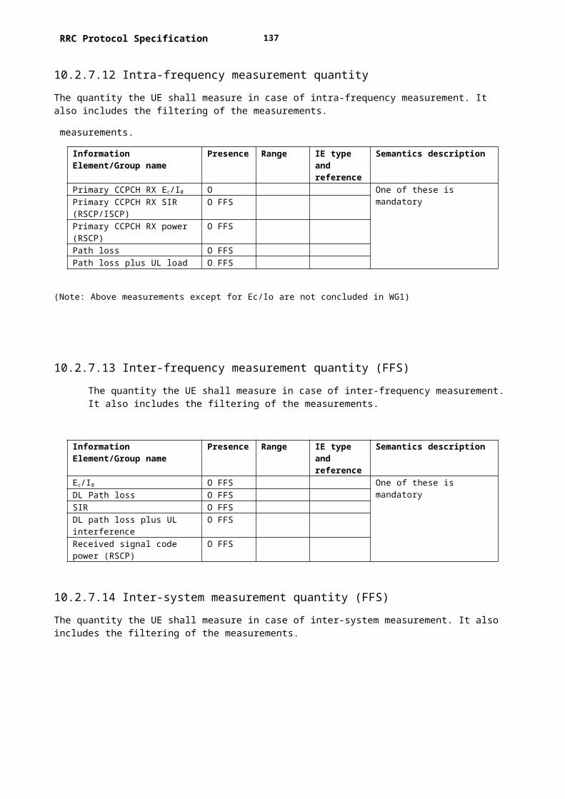
The UE shall continue reporting after the initial report by reverting to periodical measurement reporting if the reported cell is not added to the active set. This is illustrated in Figure 11. During periodic reporting the UE shall transmit MEASUREMENT REPORT messages to the RAN at predefined intervals. The reports shall include reporting information of the cells in the current active set and of the monitored cell(s) in the reporting range.
Event-triggered periodic measurement reporting shall be terminated either when there are no longer any monitored cell(s) within the reporting range or when the RAN has added cells to the active set so that it includes the maximum number of cells (defined by the reporting deactivation threshold parameter), which are allowed for event 1A to be triggered.
The reporting period is assigned by the RAN. If the reporting period is set to zero event-triggered measurement reporting shall not be applied.
15.1.3.2 Cell replacement failure
Figure 12 Periodic reporting triggered by event 1C
When a cell enters the replacement range and triggers event 1C, the UE shall transmit a MEASUREMENT REPORT to the RAN and typically this may result in the replacement of the weakest active cell. If the RAN is unable to replace the cell due to for example capacity shortage, it is beneficial to receive continuous reports in this case as well.
The UE shall revert to periodical measurement reporting if the RAN does not update the active set after the transmission of the measurement report. This is illustrated in Figure 12. During periodic reporting the UE shall transmit MEASUREMENT REPORT messages to the RAN at predefined intervals. The reports shall include reporting information of the cells in the current active set and of the monitored cell(s) in the replacement range.
Event-triggered periodic measurement reporting shall be terminated either when there are no longer any monitored cell(s) within the replacement range or when the RAN has removed cells from the active set so that there are no longer the minimum amount of active cells for event 1C to be triggered (as defined by the replacement activation threshold parameter).
The reporting period is assigned by the RAN. If the reporting period is set to zero, event-triggered measurement reporting shall not be applied.
137 RRC Protocol Specification
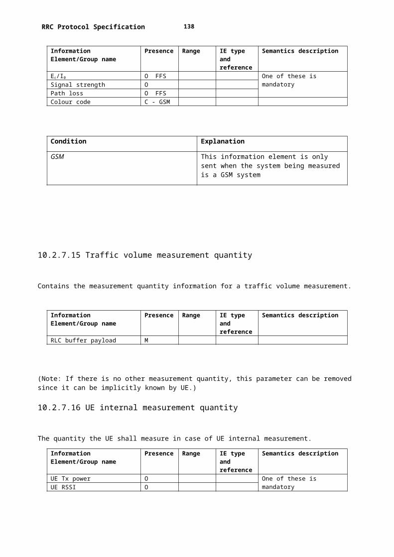
15.1.4 Mechanisms available for modifying intra-frequency measurement reporting behaviour
15.1.4.1 Hysteresis
To limit the amount of event-triggered reports, a hysteresis parameter may be connected with each reporting event given above. The value of the hysteresis is given to the UE in the Reporting criteria field of the Measurement Control message.
In the example in Figure 13, the hysteresis ensures that the event 1D (primary CCPCH 2 becomes the best cell) is not reported until the difference is equal to the hysteresis value. The fact that primary CCPCH 1 becomes best afterwards is not reported at all in the example since the primary CCPCH 1 does not become sufficiently better than the primary CCPCH 2.
Figure 13 Hysteresis limits the amount of measurement reports.
15.1.4.2 Time-to-trigger
To limit the measurement signalling load, a time-to-trigger parameter could be connected with each reporting event given above. The value of the time-to-trigger is given to the UE in the Reporting criteria field of the Measurement Control message.
The effect of the time-to-trigger is that the report is triggered only after the conditions for the event have existed for the specified time-to-trigger. In the example in Figure 14, the use of time-to-trigger means that the event (primary CCPCH 3 enters the reporting range) is not reported until is has been within the range for the time given by the time-to-trigger parameter.
138 RRC Protocol Specification

Figure 14 Time-to-trigger limits the amount of measurement reports.
Note that the time-to-trigger could be combined with hysteresis, i.e. a hysteresis value is added to the measurement quantity before evaluating if the time-to-trigger timer should be started.
15.1.4.3 Cell individual offsets
For each cell that is monitored, an offset can be assigned with inband signalling. The offset can be either positive or negative. The offset is added to the measurement quantity before the UE evaluates if an event has occurred. The UE receives the cell individual offsets for each primary CCPCH in the measurement object field of the MEASUREMENT CONTROL message.
For example, in Figure 15, since an offset is added to primary CCPCH 3, it is the dotted curve that is used to evaluate if an event occurs. Hence, this means that measurement reports from UE to UTRAN are triggered when primary CCPCH plus the corresponding offset, i.e. the dotted curve, leaves and enters the reporting range and when it gets better than primary CCPCH 1 (if these events have been ordered by UTRAN). This offset mechanism provides the network with an efficient tool to change the reporting of an individual primary CCPCH.
By applying a positive offset, as in Figure 15, the UE will send measurement reports as if the primary CCPCH is offset x dB better than what it really is. This could be useful if the operator knows that a specific cell is interesting to monitor more carefully, even though it is not so good for the moment. In the example in Figure 15, the operator might know by experience that in this area primary CCPCH 3 can become good very quickly (e.g. due to street corners) and therefore that it is worth reporting more intensively. Depending on the implemented handover evaluation algorithm, this may result in the cell with primary CCPCH 3 being included in the active set earlier than would have been the case without the positive offset.
139 RRC Protocol Specification

Figure 15 A positive offset is applied to primary CCPCH 3 before event evaluation in the UE.
Correspondingly, the operator can choose to apply a negative offset to a primary CCPCH. Then the reporting on that primary CCPCH is limited and the corresponding cell may be, at least temporarily excluded from the active set.
The cell individual offset can be seen as a tool to move the cell border. It is important to note that the offset is added before triggering events, i.e. the offset is added by the UE before evaluating if a measurement report should be sent as opposed to offsets that are applied in the network and used for the actual handover evaluation.
15.1.4.4 Forbid a Primary CCPCH to affect the reporting range
The reporting range affects the reporting events 1A and 1B presented above. The reporting range is defined relative to the best Primary CCPCH. However, there could be cases where it is good to forbid a specific Primary CCPCH to affect the reporting range. For example in Figure 16 the network has requested the UE to not let Primary CCPCH 3 affect the reporting range. This mechanism could be effective if the operator knows by experience that the quality of Primary CCPCH 3 is very unstable in a specific area and therefore should not affect the reporting of the other Primary CCPCHs.
Figure 16 Primary CCPCH 3 is forbidden to affect the reporting range.
15.1.5 Report quantitiesIn the event-triggered measurement reports, mandatory information connected to the events is always reported. For instance, at the event “a primary CCPCH enters the reporting range” the corresponding report identifies the primary CCPCH that entered the range.
However, besides this mandatory information, RAN should be able to optionally require additional measurement information in the report to support the radio network functions in RAN. Furthermore, it will allow the RAN to use the UE as a general tool for radio network optimisation if necessary.
Examples of report quantities that may be appended to the measurement reports are:[Note: This list is general and does also apply for reports of other measurement types than the intra-frequency type. The list is not final.]
Downlink transport channel block error rate
Downlink transport channel bit error rate
Downlink Ec/I0 on primary CCPCH (e.g. used for initial DL power setting on new radio links.)
Time difference between the received primary CCPCH frame-timing from the target cell and the earliest received existing DPCH path. [Note: This measurement is identified in 25.211 [2] (denoted Tm in chapter 7)]
UE transmit power
UE position (FFS)
Downlink SIR (RSCP/ISCP) on the traffic channels after RAKE combining (FFS)
140 RRC Protocol Specification

Downlink SIR (RSCP/ISCP) on primary CCPCH (e.g. used for initial DL power setting on new radio links.)(FFS)
15.2 Traffic Volume Measurements
15.2.1 Traffic Volume Measurement Quantity
For traffic volume measurements in the UE only one quantity is measured. This quantity is RLC buffer payload in number of bytes. In order to support a large variation of bit rates and RLC buffer size capabilities, a non-linear scale should be used [Note: details are FFS]. Since, the expected traffic includes both new and retransmitted RLC payload units all these should be included in the payload measure. It should also be noted that traffic volume measurements are only applicable for acknowledged and unacknowledged mode.
According to what is stated in the Measurement Control message, the UE should support measuring of buffer payload for a specific RB, RBs multiplexed onto the same Transport channel and the total UE buffer payload (the same as one transport channel for a UE that uses RACH).
15.2.2 Traffic Volume reporting events
Traffic volume can be reported in two different ways, periodical and event triggered. For periodical reporting the UE simply measures the number of bytes for the transport channel (i.e. the RLC buffers of the RBs multiplexed onto that transport channel) stated in the measurement control message and reports the traffic volume at the given time instants. Event triggered reporting is performed when a threshold is exceeded.
The reporting quantities which should be included in the report is stated in the measurement control message. This could for example be which RBs or RLC buffers to include when sending the payload to the network.
15.2.2.1 Reporting event 4 A: RLC buffer payload exceeds an absolute threshold
Figure 17 Event triggered report when RLC buffer payload exceeds a certain threshold.
If the monitored payload exceeds an absolute threshold, this is an event that could trigger a report. The corresponding report contains at least which transport channel triggered the report.
15.2.3 Traffic volume reporting mechanisms
141 RRC Protocol Specification

Traffic volume measurement triggering could be associated with both a time-to-trigger and a pending time after trigger. The time-to-trigger is used to get time domain hysteresis, i.e. the condition must be fulfilled during the time-to-trigger time before a report is sent. Pending time after trigger is used to limit consecutive reports when one traffic volume measurement report already has been sent. This is described in detail below.
15.2.3.1 Pending time after trigger
This timer is started in the UE when a measurement report has been triggered. The UE is then forbidden to send any new measurement reports with the same measurement ID during this time period even when the triggering condition is fulfilled again. Instead the UE waits until the timer has suspended. If the payload is still above the threshold when the timer has expired the UE sends a new measurement report. Otherwise it waits for a new triggering.
Figure 18 Pending time after trigger limits the amount of consecutive measurement reports.
Figure 18 shows that by increasing the pending time after trigger a triggered second event does not result in a measurement report.
15.3 UE internal measurements
15.3.1 UE internal measurement quantitiesFor UE internal measurements the following measurement quantities exist:
1. UE transmission (Tx) power
2. UE received signal strength power (RSSI)
15.3.2 UE internal measurement reporting eventsIn the Measurement reporting criteria field in the Measurement Control messages, the RAN notifies the UE of which events should trigger a measurement report. UE internal measurement reporting events that can trigger a report are given below. The reporting events are marked with vertical arrows in the figures below. All events can be combined with time-to-trigger. In that case, the measurement report is only sent if the condition for the event has been fulfilled for the time given by the time-to-trigger parameter
142 RRC Protocol Specification

[Note: The reporting events are numbered 6A, 6B, 6C,.. where 6 denotes that the event belongs to the type UE internal measurements.]
15.3.2.1 Reporting event 6A: The UE Tx power becomes larger than an absolute threshold
When this event is ordered by UTRAN in a measurement control message, the UE shall send a measurement report when the UE transmission power becomes larger than a predefined threshold. The corresponding report identifies the threshold that was exceeded.
15.3.2.2 Reporting event 6B: The UE Tx power becomes less than an absolute threshold
When this event is ordered by RAN in a measurement control message, the UE shall send a measurement report when the UE transmission power becomes less than a predefined threshold. The corresponding report identifies the threshold that the UE Tx power went below.
Figure 19 Event-triggered measurement reports when the UE Tx power becomes larger or less than absolute thresholds.
15.3.2.3 Reporting event 6C: The UE Tx power reaches its minimum value
When this event is ordered by UTRAN in a measurement control message, the UE shall send a measurement report when the UE Tx power reaches its minimum value.
143 RRC Protocol Specification
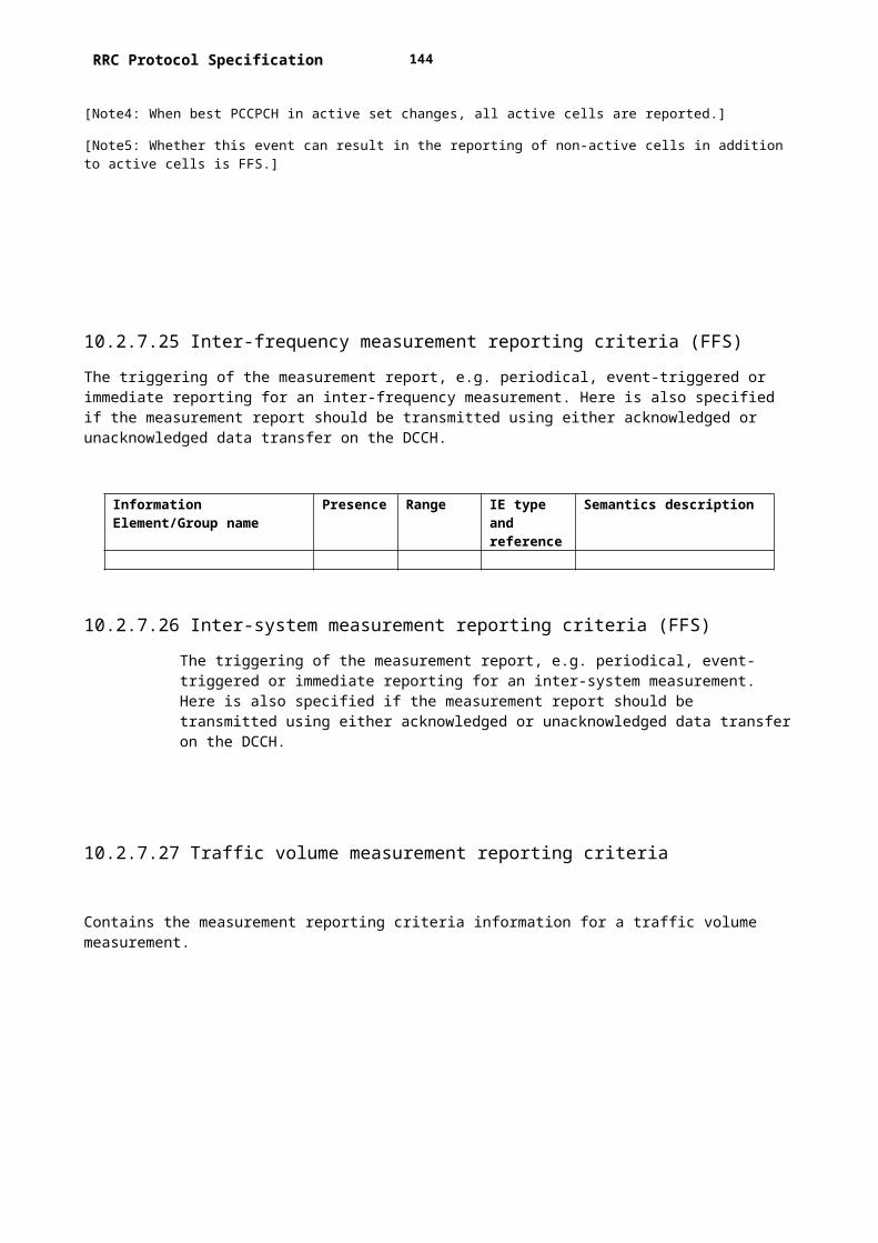
Figure 20 Event-triggered measurement report when the UE Tx power reaches its minimum value.
15.3.2.4 Reporting event 6D: The UE Tx power reaches its maximum value
When this event is ordered by RAN in a measurement control message, the UE shall send a measurement report when the UE Tx power reaches its maximum value.
Figure 21 Event-triggered report when the UE Tx power reaches its maximum value.
15.3.2.5 Reporting event 6E: The UE RSSI reaches the UE’s dynamic receiver range
When this event is ordered by RAN in a measurement control message, the UE shall send a measurement report when the UE RSSI reaches the UE’s dynamic receiver range.
15.4 Dynamic Resource Allocation Control of Uplink DCH
The network uses this procedure to dynamically control the allocation of resources on an uplink DCH, this is achieved by sending transmission probability and maximum data rate information elements.
144 RRC Protocol Specification

This procedure is initiated with a SYSTEM INFORMATION message from the NW RRC and applies to all UEs having uplink DCH's that are dynamically controlled by this procedure. Such uplink DCH's could be established through RB establishment procedure, RB reconfiguration procedure, RB release procedure or Transport Channel Reconfiguration procedure by using a ‘Dynamic Control’ parameter to indicate that the DCH is controlled by the DRAC procedure.
This function is launched by UE upon reception of a SYSTEM INFORMATION message comprising DRAC parameters (ptr, Max. bit rate).
1. The UE randomly selects p ɛ [0,1].
2. The UE then checks its permission: if p<ptr the permission is granted for Tvalidity frames, otherwise the UE waits for Tretry frames before re-attempting access.
3. A new subset of TFCS is sent to MAC, according to the permission result and to maximum bit rate granted. This subset of TFCS shall only affect DCH that are controlled by this procedure.
Transmission time validity, Time duration before retry and Silent period duration before release are indicated to the UE together with the “Dynamic Control’ parameter (i.e. at the establishment of a DCH controlled by this procedure) and may eventually be changed through RB reconfiguration.
When the UE is in soft handover, the UE may have to listen to the CCCH system information of 1 or several cells in the Active Set in order to react to the most stringent parameters, e.g. the lowest product ptr*max bit rate. In case of conflict in the reception of multiple FACH, the UE shall listen to the FACH with a priority order corresponding to the rank of cells in its Active Set (i.e. the FACH of the best received cells should be listened to first).
Whether the support for DRAC function is dependent on the UE capability or UE service capability is FFS
16 Primitives between RRC and upper layers
17 Handling of unknown, unforeseen and erroneous protocol data
This section specifies procedures for the handling of unknown, unforeseen, and erroneous protocol data by the receiving entity. These procedures are called "error handling procedures".
18 SDLThis section describes the functionality of the protocol in descriptive SDL.
145 RRC Protocol Specification

RLC Protocol Specification 146
19HistoryDocument history
Date Version Comment
1999-08-07 V1.0.0 Based on the discussion in CWTS WG1 Ad Hoc1 #2 meeting in CUPT
1999-08-30 V2.0.0 Based on CWTS WG1 Ad Hoc1 #3 meeting in Beijing
1999-10-14 V2.1.0 Based on CWTS WG1 Ad Hoc1 #4 and CWTS WG1#5 meeting in Beijing
Editor for TS c203 is:
Simin Xiong
Tel: +86 10 62302577 ext.277 fax:+86 10 62304701
This document is written using Microsoft Word 97.