TS 138 306 - V15.5.0 - 5G; NR; User Equipment (UE) radio access capabilities … · 2019-05-10 ·...
51
ETSI TS 138 306 V15.5.0 (2019-05) 5G; NR; User Equipment (UE) radio access capabilities (3GPP TS 38.306 version 15.5.0 Release 15) TECHNICAL SPECIFICATION
Transcript of TS 138 306 - V15.5.0 - 5G; NR; User Equipment (UE) radio access capabilities … · 2019-05-10 ·...
ETSI TS 138 306 V15.5.0 (2019-05)
5G; NR;
User Equipment (UE) radio access capabilities (3GPP TS 38.306 version 15.5.0 Release 15)
TECHNICAL SPECIFICATION

ETSI
ETSI TS 138 306 V15.5.0 (2019-05)13GPP TS 38.306 version 15.5.0 Release 15
Reference RTS/TSGR-0238306vf50
Keywords 5G
ETSI
650 Route des Lucioles F-06921 Sophia Antipolis Cedex - FRANCE
Tel.: +33 4 92 94 42 00 Fax: +33 4 93 65 47 16
Siret N° 348 623 562 00017 - NAF 742 C
Association à but non lucratif enregistrée à la Sous-Préfecture de Grasse (06) N° 7803/88
Important notice
The present document can be downloaded from: http://www.etsi.org/standards-search
The present document may be made available in electronic versions and/or in print. The content of any electronic and/or print versions of the present document shall not be modified without the prior written authorization of ETSI. In case of any
existing or perceived difference in contents between such versions and/or in print, the prevailing version of an ETSI deliverable is the one made publicly available in PDF format at www.etsi.org/deliver.
Users of the present document should be aware that the document may be subject to revision or change of status. Information on the current status of this and other ETSI documents is available at
https://portal.etsi.org/TB/ETSIDeliverableStatus.aspx
If you find errors in the present document, please send your comment to one of the following services: https://portal.etsi.org/People/CommiteeSupportStaff.aspx
Copyright Notification
No part may be reproduced or utilized in any form or by any means, electronic or mechanical, including photocopying and microfilm except as authorized by written permission of ETSI.
The content of the PDF version shall not be modified without the written authorization of ETSI. The copyright and the foregoing restriction extend to reproduction in all media.
© ETSI 2019.
All rights reserved.
DECTTM, PLUGTESTSTM, UMTSTM and the ETSI logo are trademarks of ETSI registered for the benefit of its Members. 3GPPTM and LTETM are trademarks of ETSI registered for the benefit of its Members and
of the 3GPP Organizational Partners. oneM2M™ logo is a trademark of ETSI registered for the benefit of its Members and
of the oneM2M Partners. GSM® and the GSM logo are trademarks registered and owned by the GSM Association.
ETSI
ETSI TS 138 306 V15.5.0 (2019-05)23GPP TS 38.306 version 15.5.0 Release 15
Intellectual Property Rights
Essential patents
IPRs essential or potentially essential to normative deliverables may have been declared to ETSI. The information pertaining to these essential IPRs, if any, is publicly available for ETSI members and non-members, and can be found in ETSI SR 000 314: "Intellectual Property Rights (IPRs); Essential, or potentially Essential, IPRs notified to ETSI in respect of ETSI standards", which is available from the ETSI Secretariat. Latest updates are available on the ETSI Web server (https://ipr.etsi.org/).
Pursuant to the ETSI IPR Policy, no investigation, including IPR searches, has been carried out by ETSI. No guarantee can be given as to the existence of other IPRs not referenced in ETSI SR 000 314 (or the updates on the ETSI Web server) which are, or may be, or may become, essential to the present document.
Trademarks
The present document may include trademarks and/or tradenames which are asserted and/or registered by their owners. ETSI claims no ownership of these except for any which are indicated as being the property of ETSI, and conveys no right to use or reproduce any trademark and/or tradename. Mention of those trademarks in the present document does not constitute an endorsement by ETSI of products, services or organizations associated with those trademarks.
Foreword This Technical Specification (TS) has been produced by ETSI 3rd Generation Partnership Project (3GPP).
The present document may refer to technical specifications or reports using their 3GPP identities, UMTS identities or GSM identities. These should be interpreted as being references to the corresponding ETSI deliverables.
The cross reference between GSM, UMTS, 3GPP and ETSI identities can be found under http://webapp.etsi.org/key/queryform.asp.
Modal verbs terminology In the present document "shall", "shall not", "should", "should not", "may", "need not", "will", "will not", "can" and "cannot" are to be interpreted as described in clause 3.2 of the ETSI Drafting Rules (Verbal forms for the expression of provisions).
"must" and "must not" are NOT allowed in ETSI deliverables except when used in direct citation.

ETSI
ETSI TS 138 306 V15.5.0 (2019-05)33GPP TS 38.306 version 15.5.0 Release 15
Contents
Intellectual Property Rights ................................................................................................................................ 2
Foreword ............................................................................................................................................................. 2
Modal verbs terminology .................................................................................................................................... 2
Foreword ............................................................................................................................................................. 4
1 Scope ........................................................................................................................................................ 5
2 References ................................................................................................................................................ 5
3 Definitions, symbols and abbreviations ................................................................................................... 6
3.1 Definitions .......................................................................................................................................................... 6
3.2 Symbols .............................................................................................................................................................. 6
3.3 Abbreviations ..................................................................................................................................................... 6
4 UE radio access capability parameters ..................................................................................................... 7
4.1 Supported max data rate ..................................................................................................................................... 7
4.1.1 General .......................................................................................................................................................... 7
4.1.2 Supported max data rate ............................................................................................................................... 7
4.1.3 Void .............................................................................................................................................................. 8
4.1.4 Total layer 2 buffer size ................................................................................................................................ 8
4.2 UE Capability Parameters .................................................................................................................................. 9
4.2.1 Introduction................................................................................................................................................... 9
4.2.2 General parameters ..................................................................................................................................... 10
4.2.3 SDAP Parameters ....................................................................................................................................... 10
4.2.4 PDCP Parameters ........................................................................................................................................ 11
4.2.5 RLC parameters .......................................................................................................................................... 11
4.2.6 MAC parameters ......................................................................................................................................... 12
4.2.7 Physical layer parameters ........................................................................................................................... 13
4.2.7.1 BandCombinationList parameters ......................................................................................................... 13
4.2.7.2 BandNR parameters .............................................................................................................................. 16
4.2.7.3 CA-ParametersEUTRA ......................................................................................................................... 24
4.2.7.4 CA-ParametersNR ................................................................................................................................ 25
4.2.7.5 FeatureSetDownlink parameters ........................................................................................................... 28
4.2.7.6 FeatureSetDownlinkPerCC parameters ................................................................................................ 31
4.2.7.7 FeatureSetUplink parameters ................................................................................................................ 32
4.2.7.8 FeatureSetUplinkPerCC parameters ..................................................................................................... 35
4.2.7.9 MRDC-Parameters ............................................................................................................................... 36
4.2.7.10 Phy-Parameters .................................................................................................................................... 36
4.2.7.11 Other PHY parameters .......................................................................................................................... 42
4.2.8 Void ............................................................................................................................................................ 43
4.2.9 MeasAndMobParameters ........................................................................................................................... 44
4.2.10 Inter-RAT parameters ................................................................................................................................. 47
4.2.10.1 Void....................................................................................................................................................... 47
4.2.10.2 Void....................................................................................................................................................... 47
4.2.11 Void ............................................................................................................................................................ 47
4.2.12 Void ............................................................................................................................................................ 47
4.2.13 IMS Parameters .......................................................................................................................................... 47
4.2.14 RRC buffer size .......................................................................................................................................... 47
5 Optional features without UE radio access capability parameters ......................................................... 47
6 Conditionally mandatory features without UE radio access capability parameters ............................... 47
7 Void ........................................................................................................................................................ 48
8 UE Capability Constraints ...................................................................................................................... 48
Annex A (informative): Change history ............................................................................................... 49
History .............................................................................................................................................................. 50

ETSI
ETSI TS 138 306 V15.5.0 (2019-05)43GPP TS 38.306 version 15.5.0 Release 15
Foreword This Technical Specification has been produced by the 3rd Generation Partnership Project (3GPP).
The contents of the present document are subject to continuing work within the TSG and may change following formal TSG approval. Should the TSG modify the contents of the present document, it will be re-released by the TSG with an identifying change of release date and an increase in version number as follows:
Version x.y.z
where:
x the first digit:
1 presented to TSG for information;
2 presented to TSG for approval;
3 or greater indicates TSG approved document under change control.
y the second digit is incremented for all changes of substance, i.e. technical enhancements, corrections, updates, etc.
z the third digit is incremented when editorial only changes have been incorporated in the document.
ETSI
ETSI TS 138 306 V15.5.0 (2019-05)53GPP TS 38.306 version 15.5.0 Release 15
1 Scope The present document defines the NR UE Radio Access Capability Parameters.
2 References The following documents contain provisions which, through reference in this text, constitute provisions of the present document.
- References are either specific (identified by date of publication, edition number, version number, etc.) or non-specific.
- For a specific reference, subsequent revisions do not apply.
- For a non-specific reference, the latest version applies. In the case of a reference to a 3GPP document (including a GSM document), a non-specific reference implicitly refers to the latest version of that document in the same Release as the present document.
[1] 3GPP TR 21.905: "Vocabulary for 3GPP Specifications".
[2] 3GPP TS 38.101-1: "NR; User Equipment (UE) radio transmission and reception Part 1: Range 1 Standalone".
[3] 3GPP TS 38.101-2: "NR; User Equipment (UE) radio transmission and reception Part 2: Range 2 Standalone".
[4] 3GPP TS 38.101-3: "NR; User Equipment (UE) radio transmission and reception Part 3: Range 1 and Range 2 Interworking operation with other radios".
[5] 3GPP TS 38.133: "NR; Requirements for support of radio resource management".
[6] 3GPP TS 38.211: "NR; Physical channels and modulation".
[7] 3GPP TS 37.340: "Evolved Universal Terrestrial Radio Access (E-UTRA) and NR Multi-connectivity".
[8] 3GPP TS 38.321: "NR; Medium Access Control (MAC) protocol specification".
[9] 3GPP TS 38.331: "NR; Radio Resource Control (RRC) protocol specification".
[10] 3GPP TS 38.212: "NR; Multiplexing and channel coding".
[11] 3GPP TS 38.213: "NR; Physical layer procedures for control".
[12] 3GPP TS 38.214: "NR; Physical layer procedures for data".
[13] 3GPP TS 38.215: "NR; Physical layer measurements".
[14] 3GPP TS 36.101: "Evolved Universal Terrestrial Radio Access (E-UTRA) radio transmission and reception".
[15] 3GPP TS 36.306: "Evolved Universal Terrestrial Radio Access (E-UTRA) User Equipment (UE) radio access capabilities".
[16] 3GPP TS 38.323: "NR; Packet Data Convergence Protocol (PDCP) specification".
[17] 3GPP TS 36.331: "Evolved Universal Terrestrial Radio Access (E-UTRA) Radio Resource Control (RRC); Protocol Specification".
ETSI
ETSI TS 138 306 V15.5.0 (2019-05)63GPP TS 38.306 version 15.5.0 Release 15
3 Definitions, symbols and abbreviations
3.1 Definitions For the purposes of the present document, the terms and definitions given in 3GPP TR 21.905 [1] and the following apply. A term defined in the present document takes precedence over the definition of the same term, if any, in 3GPP TR 21.905 [1].
Fallback band combination: A band combination that would result from another band combination by releasing at least one SCell or uplink configuration of SCell. An intra-band non-contiguous band combination is not considered to be a fallback band combination of an intra-band contiguous band combination.
Fallback per band feature set: A feature set per band that has same or lower values than the reported values from the reported feature set per band for a given band.
Fallback per CC feature set: A feature set per CC that has lower value of UE supported MIMO layers and BW while keeping the numerology and other parameters the same from the reported feature set per CC for a given carrier per band.
3.2 Symbols For the purposes of the present document, the following symbols apply:
MaxDLDataRate: Maximum DL data rate MaxDLDataRate_MN: Maximum DL data rate in the MN MaxDLDataRate_SN: Maximum DL data rate in the SN MaxULDataRate: Maximum UL data rate
3.3 Abbreviations For the purposes of the present document, the abbreviations given in 3GPP TR 21.905 [1] and the following apply. An abbreviation defined in the present document takes precedence over the definition of the same abbreviation, if any, in 3GPP TR 21.905 [1].
BC Band Combination DL Downlink FS Feature Set FSPC Feature Set Per Component-carrier MAC Medium Access Control MCG Master Cell Group MN Master Node MR-DC Multi-RAT Dual Connectivity PDCP Packet Data Convergence Protocol RLC Radio Link Control RTT Round Trip Time SCG Secondary Cell Group SDAP Service Data Adaptation Protocol SN Secondary Node UL Uplink

ETSI
ETSI TS 138 306 V15.5.0 (2019-05)73GPP TS 38.306 version 15.5.0 Release 15
4 UE radio access capability parameters
4.1 Supported max data rate
4.1.1 General
The DL and UL max data rate supported by the UE is calculated by band or band combinations supported by the UE. A UE supporting MR-DC shall support the calculated DL and UL max data rate defined in 4.1.2.
4.1.2 Supported max data rate
For NR, the approximate data rate for a given number of aggregated carriers in a band or band combination is computed as follows.
( )=
−
−⋅
⋅⋅⋅⋅⋅⋅=
J
j
j
s
jBWPRBjj
mj OH
T
NRfQv
Layers1
)(),(
max)()()(6 1
1210Mbps)(in rate data μ
μ
wherein
J is the number of aggregated component carriers in a band or band combination Rmax = 948/1024 For the j-th CC,
is the maximum number of supported layers given by higher layer parameter maxNumberMIMO-
LayersPDSCH for downlink and maximum of higher layer parameters maxNumberMIMO-LayersCB-PUSCH and maxNumberMIMO-LayersNonCB-PUSCH for uplink.
)( jmQ is the maximum supported modulation order given by higher layer parameter
supportedModulationOrderDL for downlink and higher layer parameter supportedModulationOrderUL for uplink.
)( jf is the scaling factor given by higher layer parameter scalingFactor and can take the values 1, 0.8, 0.75,
and 0.4.
μ is the numerology (as defined in TS 38.211 [6])
μ
sT is the average OFDM symbol duration in a subframe for numerology μ , i.e.
μμ
214
10 3
⋅=
−
sT. Note that
normal cyclic prefix is assumed.
( ) μ,jBW
PRBN is the maximum RB allocation in bandwidth ( )jBW with numerology μ , as defined in 5.3 TS
38.101-1 [2] and 5.3 TS 38.101-2 [3], where ( )jBW is the UE supported maximum bandwidth in the given
band or band combination.
)( jOH is the overhead and takes the following values
0.14, for frequency range FR1 for DL 0.18, for frequency range FR2 for DL 0.08, for frequency range FR1 for UL 0.10, for frequency range FR2 for UL
NOTE: Only one of the UL or SUL carriers (the one with the higher data rate) is counted for a cell operating SUL.
The approximate maximum data rate can be computed as the maximum of the approximate data rates computed using the above formula for each of the supported band or band combinations.
)( j
Layersv

ETSI
ETSI TS 138 306 V15.5.0 (2019-05)83GPP TS 38.306 version 15.5.0 Release 15
For EUTRA in case of MR-DC, the approximate data rate for a given number of aggregated carriers in a band or band combination is computed as follows.
Data rate (in Mbps) = 3
110
J
jjTBS−
=⋅
wherein
J is the number of aggregated EUTRA component carriers in MR-DC band combination
����
is the total maximum number of DL-SCH transport block bits received within a 1ms TTI for j-th CC, as derived from TS36.213 [22] based on the UE supported maximum MIMO layers for the j-th carrier, and based on the modulation order and number of PRBs based on the bandwidth of the j-th carrier.
The approximate maximum data rate can be computed as the maximum of the approximate data rates computed using the above formula for each of the supported band or band combinations.
For MR-DC, the approximate maximum data rate is computed as the sum of the approximate maximum data rates from NR and EUTRA.
4.1.3 Void
4.1.4 Total layer 2 buffer size
The total layer 2 buffer size is defined as the sum of the number of bytes that the UE is capable of storing in the RLC transmission windows and RLC reception and reordering windows and also in PDCP reordering windows for all radio bearers.
The required total layer 2 buffer size in MR-DC and NR-DC is the maximum value of the calculated values based on the following equations:
- MaxULDataRate_MN * RLCRTT_MN + MaxULDataRate_SN * RLCRTT_SN + MaxDLDataRate_SN * RLCRTT_SN + MaxDLDataRate_MN * (RLCRTT_SN + X2/Xn delay + Queuing in SN)
- MaxULDataRate_MN * RLCRTT_MN + MaxULDataRate_SN * RLCRTT_SN + MaxDLDataRate_MN * RLCRTT_MN + MaxDLDataRate_SN * (RLCRTT_MN + X2/Xn delay + Queuing in MN)
Otherwise it is calculated by MaxDLDataRate * RLC RTT + MaxULDataRate * RLC RTT.
NOTE: Additional L2 buffer required for preprocessing of data is not taken into account in above formula.
The required total layer 2 buffer size is determined as the maximum total layer 2 buffer size of all the calculated ones for each band combination and the applicable Feature Set combination in the supported MR-DC or NR band combinations. The RLC RTT for NR cell group corresponds to the smallest SCS numerology supported in the band combination and the applicable Feature Set combination.
wherein
X2/Xn delay + Queuing in SN = 25ms if SCG is NR, and 55ms if SCG is EUTRA
X2/Xn delay + Queuing in MN = 25ms if MCG is NR, and 55ms if MCG is EUTRA
RLC RTT for EUTRA cell group = 75ms
RLC RTT for NR cell group is defined in Table 4.1.4-1
Table 4.1.4-1: RLC RTT for NR cell group per SCS
SCS (KHz) RLC RTT (ms) 15KHz 50 30KHz 40 60KHz 30
120KHz 20

ETSI
ETSI TS 138 306 V15.5.0 (2019-05)93GPP TS 38.306 version 15.5.0 Release 15
4.2 UE Capability Parameters
4.2.1 Introduction
The following subclauses define the UE radio access capability parameters. Only parameters for which there is the possibility for UEs to signal different values are considered as UE radio access capability parameters. Therefore, mandatory features without capability parameters that are the same for all UEs are not listed here.
The UE may support different functionalities between FDD and TDD, and/or between FR1 and FR2. The UE shall indicate the UE capabilities as follows. In the table of UE capability parameter in subsequent sub-clauses, "Yes" in the column by "FDD-TDD DIFF" and "FR1-FR2 DIFF" indicates the UE capability field can have a different value for between FDD and TDD or between FR1 and FR2 and "No" indicates if it cannot. "FD" in the column indicates to refer the associated field description. "FR1 only" or "FR2 only" in the column indicates the associated feature is only supported in FR1 or FR2 and "TDD only" indicates the associated feature is only supported in TDD.
1> set all fields of UE-NR/MRDC-Capability except fdd-Add-UE-NR/MRDC-Capabilities, tdd-Add-UE-NR/MRDC-Capabilities, fr1-Add-UE-NR/MRDC-Capabilities and fr2-Add-UE-NR/MRDC-Capabilities, to include the values applicable for all duplex mode(s) and frequency range(s) that the UE supports;
1> if UE supports both FDD and TDD and if (some of) the UE capability fields have a different value for FDD and TDD
2> if for FDD, the UE supports additional functionality compared to what is indicated by the previous fields of UE-NR/MRDC-Capability:
3> include field fdd-Add-UE-NR/MRDC-Capabilities and set it to include fields reflecting the additional functionality applicable for FDD;
2> if for TDD, the UE supports additional functionality compared to what is indicated by the previous fields of UE-NR/MRDC-Capability:
3> include field tdd-Add-UE-NR/MRDC-Capabilities and set it to include fields reflecting the additional functionality applicable for TDD;
1> if UE supports both FR1 and FR2 and if (some of) the UE capability fields have a different value for FR1 and FR2:
2> if for FR1, the UE supports additional functionality compared to what is indicated by the previous fields of UE-NR/MRDC-Capability:
3> include field fr1-Add-UE-NR/MRDC-Capabilities and set it to include fields reflecting the additional functionality applicable for FR1;
2> if for FR2, the UE supports additional functionality compared to what is indicated by the previous fields of UE-NR/MRDC-Capability:
3> include field fr2-Add-UE-NR/MRDC-Capabilities and set it to include fields reflecting the additional functionality applicable for FR2;
NOTE: The fields which indicate "shall be set to 1" in the following tables means these features are purely mandatory and are assumed they are the same as mandatory without capability signaling.
For optional features, the UE radio access capability parameter indicates whether the feature has been implemented and successfully tested. For mandatory features with the UE radio access capability parameter, the parameter indicates whether the feature has been successfully tested. In the table of UE capability parameter in subsequent sub-clauses, "Yes" in the column by "M" indicates the associated feature is mandatory and "No" indicates the associated feature is optional. "CY" in the column indicates the associated feature is conditional mandatory and the condition is described in the field description. "FD" in the column indicates to refer the associated field description.
UE capability parameters have hierarchical structure. In the table of UE capability parameter in subsequent sub-clauses, "Per" indicates the level the associated parameter is included. "UE" in the column indicates the associated parameter is signalled per UE, "Band" indicates it is signalled per band, "BC" indicates it is signalled per band combination, "FS" indicates it is signalled per feature set (per band per band combination), "FSPC" indicates it is signalled per feature set
ETSI
ETSI TS 138 306 V15.5.0 (2019-05)103GPP TS 38.306 version 15.5.0 Release 15
per component carrier (per CC per band per band combination), and "FD" in the column indicates to refer the associated field description.
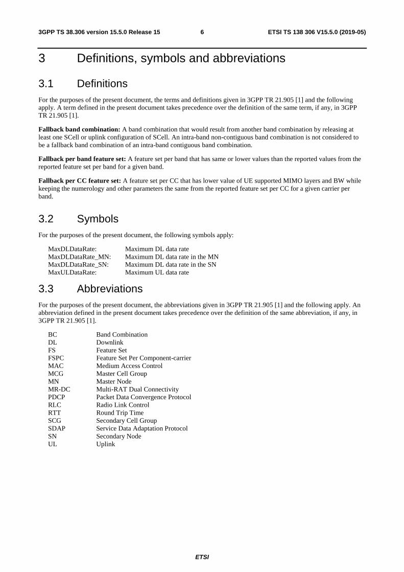
4.2.2 General parameters
Definitions for parameters Per M FDD-TDD DIFF
FR1-FR2 DIFF
delayBudgetReporting Indicates whether the UE supports delay budget reporting as specified in TS 38.331 [9].
UE No No No
inactiveState Indicates whether the UE supports RRC_inactive as specified in TS 38.331 [9].
UE Yes No No
overheatingInd Indicates whether the UE supports overheating assistance information.
UE No No No
reducedCP-Latency Indicates whether the UE supports reduced control plane latency as defined in TS 38.331 [9]
UE No No No
splitSRB-WithOneUL-Path Indicates whether the UE supports UL transmission via either MCG path or SCG path for the split SRB as specified in TS 37.340 [7].
UE No Yes No
splitDRB-withUL-Both-MCG-SCG Indicates whether the UE supports UL transmission via both MCG path and SCG path for the split DRB as specified in TS 37.340 [7].
UE Yes Yes No
srb3 Indicates whether the UE supports direct SRB between the SN and the UE as specified in TS 37.340 [7].
UE Yes Yes No
v2x-EUTRA Indicates whether the UE supports EUTRA V2X according to UE-EUTRA-Capability as defined in [x], independent of the configured EN-DC band combination.
UE No No No
4.2.3 SDAP Parameters
Definitions for parameters Per M FDD-TDD DIFF
as-ReflectiveQoS Indicates whether the UE supports AS reflective QoS.
UE No No

ETSI
ETSI TS 138 306 V15.5.0 (2019-05)113GPP TS 38.306 version 15.5.0 Release 15
4.2.4 PDCP Parameters
Definitions for parameters Per M FDD-TDD DIFF
continueROHC-Context Defines whether the UE supports ROHC context continuation operation where the UE does not reset the current ROHC context upon handover.
UE No No
maxNumberROHC-ContextSessions Defines the maximum number of header compression context sessions supported by the UE, excluding context sessions that leave all headers uncompressed.
UE No No
outOfOrderDelivery Indicates whether UE supports Out of order delivery of data to upper layers by PDCP.
UE No No
pdcp-DuplicationMCG-OrSCG-DRB Indicates whether the UE supports CA-based PDCP duplication over MCG or SCG DRB as specified in TS 38.323 [16].
UE No No
pdcp-DuplicationSplitDRB Indicates whether the UE supports PDCP duplication over split DRB as specified in TS 38.323 [16].
UE No No
pdcp-DuplicationSplitSRB Indicates whether the UE supports PDCP duplication over split SRB1/2 as specified in TS 38.323 [16].
UE No No
pdcp-DuplicationSRB Indicates whether the UE supports CA-based PDCP duplication over SRB1/2 and/or, if EN-DC is supported, SRB3 as specified in TS 38.323 [16].
UE No No
shortSN Indicates whether the UE supports 12 bit length of PDCP sequence number.
UE Yes No
supportedROHC-Profiles Defines which ROHC profiles from the list below are supported by the UE:
- 0x0000 ROHC No compression (RFC 5795) - 0x0001 ROHC RTP/UDP/IP (RFC 3095, RFC 4815) - 0x0002 ROHC UDP/IP (RFC 3095, RFC 4815) - 0x0003 ROHC ESP/IP (RFC 3095, RFC 4815) - 0x0004 ROHC IP (RFC 3843, RFC 4815) - 0x0006 ROHC TCP/IP (RFC 6846) - 0x0101 ROHC RTP/UDP/IP (RFC 5225) - 0x0102 ROHC UDP/IP (RFC 5225) - 0x0103 ROHC ESP/IP (RFC 5225) - 0x0104 ROHC IP (RFC 5225)
A UE that supports one or more of the listed ROHC profiles shall support ROHC profile 0x0000 ROHC uncompressed (RFC 5795).
UE No No
uplinkOnlyROHC-Profiles Indicates which ROHC profile(s) from the list below are supported in uplink-only ROHC operation by the UE.
- 0x0006 ROHC TCP (RFC [6846])
A UE that supports uplink-only ROHC profile(s) shall support ROHC profile 0x0000 ROHC uncompressed (RFC 5795).
UE No No
4.2.5 RLC parameters
Definitions for parameters Per M FDD-TDD DIFF
am-WithShortSN Indicates whether the UE supports AM DRB with 12 bit length of RLC sequence number.
UE Yes No
um-WIthLongSN Indicates whether the UE supports UM DRB with 12 bit length of RLC sequence number.
UE Yes No
um-WithShortSN Indicates whether the UE supports UM DRB with 6 bit length of RLC sequence number.
UE Yes No
ETSI
ETSI TS 138 306 V15.5.0 (2019-05)123GPP TS 38.306 version 15.5.0 Release 15
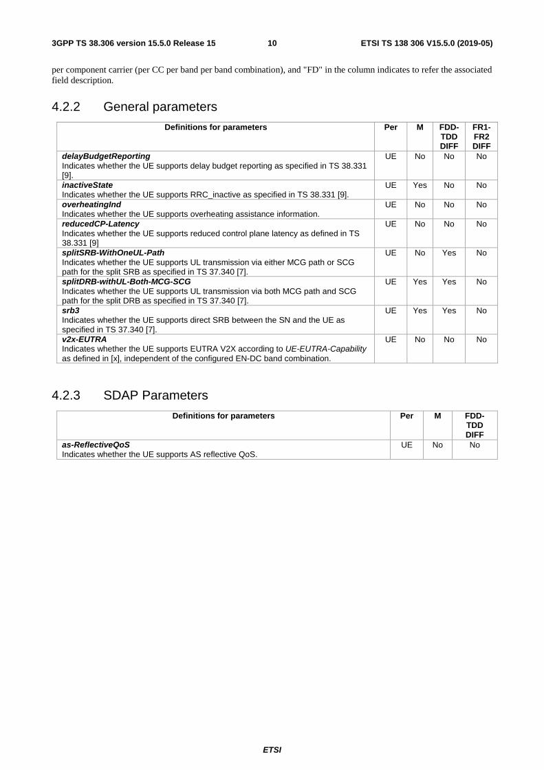
4.2.6 MAC parameters
Definitions for parameters Per M FDD-TDD DIFF
FR1-FR2 DIFF
lch-ToSCellRestriction Indicates whether the UE supports restricting data transmission from a given LCH to a configured (sub-) set of serving cells (see allowedServingCells in LogicalChannelConfig). A UE supporting pdcp-Duplication (see PDCP-Config) shall also support lch-ToSCellRestriction.
UE No No No
lcp-Restriction Indicates whether UE supports the selection of logical channels for each UL grant based on RRC configured restriction.
UE No No No
logicalChannelSR-DelayTimer Indicates whether the UE supports the logicalChannelSR-DelayTimer as specified in TS 38.321 [8].
UE No Yes No
longDRX-Cycle Indicates whether UE supports long DRX cycle as specified in TS 38.321 [8].
UE Yes Yes No
multipleConfiguredGrants Indicates whether UE supports more than one configured grant configurations (including both Type 1 and Type 2) in a cell group. For each cell, the UE supports at most one configured grant per BWP and the maximum number of configured grant configurations per cell group is 2. If absent, for each configured cell group, the UE only supports one configured grant configuration on one serving cell.
UE No Yes No
multipleSR-Configurations Indicates whether the UE supports TS 38.321 [8] SR configurations per cell group.
UE No Yes No
recommendedBitRate Indicates whether the UE supports the bit rate recommendation message from the gNB to the UE as specified in TS 38.321 [8].
UE No No No
recommendedBitRateQuery Indicates whether the UE supports the bit rate recommendation query message from the UE to the gNB as specified in TS 38.321 [8]. This field is only applicable if the UE supports recommendedBitRate.
UE No No No
shortDRX-Cycle Indicates whether UE supports short DRX cycle as specified in TS 38.321 [8].
UE Yes Yes No
skipUplinkTxDynamic Indicates whether the UE supports skipping of UL transmission for an uplink grant indicated on PDCCH if no data is available for transmission as specified in TS 38.321 [8].
UE No Yes No
ETSI
ETSI TS 138 306 V15.5.0 (2019-05)133GPP TS 38.306 version 15.5.0 Release 15
4.2.7 Physical layer parameters
4.2.7.1 BandCombinationList parameters
ETSI
ETSI TS 138 306 V15.5.0 (2019-05)143GPP TS 38.306 version 15.5.0 Release 15
Definitions for parameters Per M FDD-TDD DIFF
FR1-FR2 DIFF
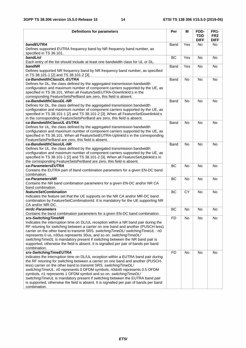
bandEUTRA Defines supported EUTRA frequency band by NR frequency band number, as specified in TS 36.101.
Band Yes No No
bandList Each entry of the list should include at least one bandwidth class for UL or DL.
BC Yes No No
bandNR Defines supported NR frequency band by NR frequency band number, as specified in TS 38.101-1 [2] and TS 38.101-2 [3].
Band Yes No No
ca-BandwidthClassDL-EUTRA Defines for DL, the class defined by the aggregated transmission bandwidth configuration and maximum number of component carriers supported by the UE, as specified in TS 36.101. When all FeatureSetEUTRA-DownlinkId:s in the corresponding FeatureSetsPerBand are zero, this field is absent.
Band No No No
ca-BandwidthClassDL-NR Defines for DL, the class defined by the aggregated transmission bandwidth configuration and maximum number of component carriers supported by the UE, as specified in TS 38.101-1 [2] and TS 38.101-2 [3]. When all FeatureSetDownlinkId:s in the corresponding FeatureSetsPerBand are zero, this field is absent.
Band No No No
ca-BandwidthClassUL-EUTRA Defines for UL, the class defined by the aggregated transmission bandwidth configuration and maximum number of component carriers supported by the UE, as specified in TS 36.101. When all FeatureSetEUTRA-UplinkId:s in the corresponding FeatureSetsPerBand are zero, this field is absent.
Band No No No
ca-BandwidthClassUL-NR Defines for UL, the class defined by the aggregated transmission bandwidth configuration and maximum number of component carriers supported by the UE, as specified in TS 38.101-1 [2] and TS 38.101-2 [3]. When all FeatureSetUplinkId:s in the corresponding FeatureSetsPerBand are zero, this field is absent.
Band No No No
ca-ParametersEUTRA Contains the EUTRA part of band combination parameters for a given EN-DC band combination.
BC No No No
ca-ParametersNR Contains the NR band combination parameters for a given EN-DC and/or NR CA band combination.
BC No No No
featureSetCombination Indicates the feature set that the UE supports on the NR CA and/or MR-DC band combination by FeatureSetCombinationId. It is mandatory for the UE supporting NR CA and/or MR-DC.
BC CY No No
mrdc-Parameters Contains the band combination parameters for a given EN-DC band combination.
BC No No No
srs-SwitchingTimeNR Indicates the interruption time on DL/UL reception within a NR band pair during the RF retuning for switching between a carrier on one band and another (PUSCH-less) carrier on the other band to transmit SRS. switchingTimeDL/ switchingTimeUL : n0 represents 0 us, n30us represents 30us, and so on. switchingTimeDL/ switchingTimeDL is mandatory present if switching between the NR band pair is supported, otherwise the field is absent. It is signalled per pair of bands per band combination.
FD No No No
srs-SwitchingTimeEUTRA indicates the interruption time on DL/UL reception within a EUTRA band pair during the RF retuning for switching between a carrier on one band and another (PUSCH-less) carrier on the other band to transmit SRS. switchingTimeDL/ switchingTimeUL: n0 represents 0 OFDM symbols, n0dot5 represents 0.5 OFDM symbols, n1 represents 1 OFDM symbol and so on. switchingTimeDL/ switchingTimeUL is mandatory present if switching between the EUTRA band pair is supported, otherwise the field is absent. It is signalled per pair of bands per band combination.
FD No No No

ETSI
ETSI TS 138 306 V15.5.0 (2019-05)153GPP TS 38.306 version 15.5.0 Release 15
SRS-TxSwitch Defines whether UE supports SRS antenna port switching as defined in clause 6.2.1.2 of TS 38.214 [12]. The capability signalling comprises of the following parameters:
- supportedSRS-TxPortSwitch indicates SRS Tx port switching pattern supported by the UE. The indicated UE antenna switching capability of ′xTyR′ corresponds to a UE, capable of SRS transmission on ′x′ antenna ports over total of ′y′ antennas, where ′y′ corresponds to all or subset of UE receive antennas, where 2T4R is two pairs of antennas;
- txSwitchImpactToRx indicates the entry number of the first-listed band with UL in the band combination that affects this DL;
- txSwitchWithAnotherBand indicates the entry number of the first-listed band with UL in the band combination that switches together with this UL.
For txSwitchImpactToRx and txSwitchWithAnotherBand, value 1 means first entry, value 2 means second entry and so on. All DL and UL that switch together indicate the same entry number. The UE is restricted not to include fallback band combinations for the purpose of indicating different SRS antenna switching capabilities.
BC Yes No No
supportedBandwidthCombinationSet Defines the supported bandwidth combination for the band combination set as defined in the TS 38.101-1 [2], TS 38.101-2 [3] and TS 38.101-3 [4]. Field encoded as a bit map, where bit N is set to "1" if UE support Bandwidth Combination Set N for this band combination as defined in the TS 38.101-1 [2], TS 38.101-2 [3] and TS 38.101-3 [4]. The leading / leftmost bit (bit 0) corresponds to the Bandwidth Combination Set 0, the next bit corresponds to the Bandwidth Combination Set 1 and so on.
BC Tbd No No

ETSI
ETSI TS 138 306 V15.5.0 (2019-05)163GPP TS 38.306 version 15.5.0 Release 15
4.2.7.2 BandNR parameters

ETSI
ETSI TS 138 306 V15.5.0 (2019-05)173GPP TS 38.306 version 15.5.0 Release 15
Definitions for parameters Per M FDD-TDD DIFF
FR1-FR2 DIFF
additionalActiveTCI-StatePDCCH Indicates whether the UE supports one additional active TCI-State for control in addition to the supported number of active TCI-States for PDSCH. The UE can include this field only if maxNumberActiveTCI-PerBWP in tci-StatePDSCH is set to 1. Otherwise, the UE does not include this field.
Band Yes No No
aperiodicBeamReport Indicates whether the UE supports aperiodic 'CRI/RSRP' or 'SSBRI/RSRP' reporting on PUSCH.
Band Yes No No
aperiodicTRS Indicates whether the UE supports DCI triggering aperiodic TRS associated with periodic TRS.
Band No No Yes
bandNR Defines supported NR frequency band by NR frequency band number, as specified in TS 38.101-1 [2] and TS 38.101-2 [3].
Band Yes No No
beamCorrespondenceWithoutUL-BeamSweeping Indicates whether UE supports FR2 beam correspondence as specified in TS38.101-2 [3], subclause 6.6. The UE that fulfils the beam correspondence requirement without the uplink beam sweeping (as specified inTS38.101-2 [3], subclause 6.6) shall set the bit to 1. The UE that fulfils the beam correspondence requirement with the uplink beam sweeping (as specified inTS38.101-2 [3], subclause 6.6) shall set the bit to 0.
Band Yes No FR2 only
beamCorrespondenceCA Indicates whether UE configured with CA supports the same beam correspondence across all CCs as defined in <TBD RAN4 >.
Band Tbd No No
beamManagementSSB-CSI-RS Defines support of SS/PBCH and CSI-RS based RSRP measurements. The capability comprises signalling of
- maxNumberSSB-CSI-RS-ResourceOneTx indicates maximum total number of configured one port NZP CSI-RS resources and SS/PBCH blocks that are supported by the UE for 'CRI/RSRP' and 'SSBRI/RSRP' reporting within a slot and across all serving cells. Support of n8 is mandatory.
- maxNumberCSI-RS-Resource indicates maximum total number of configured NZP-CSI-RS resources that are supported by the UE for 'CRI/RSRP' reporting across all serving cells. It is mandated to report at least n8 for FR1.
- maxNumberCSI-RS-ResourceTwoTx indicates maximum total number of two ports NZP CSI-RS resources that are supported by the UE for 'CRI/RSRP' reporting within a slot and across all serving cells.
- supportedCSI-RS-Density indicates density of one RE per PRB for one port NZP CSI-RS resource for RSRP reporting, if supported. At least density of CSI-RS = 3 or both 1 and 3 is mandatory.
- maxNumberAperiodicCSI-RS-Resource indicates maximum number of configured aperiodic CSI-RS resources across all CCs. For FR1 and FR2, the UE is mandated to report at least n4.
Band Yes No Yes
beamReportTiming Indicates the number of OFDM symbols between the last symbol of SSB/CSI-RS and the first symbol of the transmission channel containing beam report. The UE includes this field for each supported sub-carrier spacing.
Band Yes No No
beamSwitchTiming Indicates the minimum number of OFDM symbols between the DCI triggering of aperiodic CSI-RS and aperiodic CSI-RS transmission. The number of OFDM symbols is measured from the last symbol containing the indication to the first symbol of CSI-RS. The UE includes this field for each supported sub-carrier spacing.
Band No No FR2 only
bwp-DiffNumerology Indicates whether the UE supports BWP adaptation up to 4 BWPs with the different numerologies, via DCI and timer. For the UE capable of this feature, the bandwidth of a UE-specific RRC configured BWP includes the bandwidth of the CORESET#0 (if CORESET#0 is present) and SSB for PCell and PSCell (if configured). For SCell(s), the bandwidth of the UE-specific RRC configured BWP includes SSB, if there is SSB on SCell(s).
Band No No No

ETSI
ETSI TS 138 306 V15.5.0 (2019-05)183GPP TS 38.306 version 15.5.0 Release 15
bwp-SameNumerology Defines type A/B BWP adaptation (up to 2/4 BWPs) with the same numerology, via DCI and timer. For the UE capable of this feature, the bandwidth of a UE-specific RRC configured BWP includes the bandwidth of the CORESET#0 (if CORESET#0 is present) and SSB for PCell and PSCell (if configured). For SCell(s), the bandwidth of the UE-specific RRC configured BWP includes SSB, if there is SSB on SCell(s).
Band No No No
bwp-WithoutRestriction Indicates support of BWP operation without bandwidth restriction. The Bandwidth restriction in terms of BWP for PCell and PSCell means that the bandwidth of a UE-specific RRC configured BWP may not include the bandwidth of initial DL BWP and SSB. For SCell(s), it means that the bandwidth of BWP may not include SSB.
Band No No No
channelBWs-DL Indicates for each subcarrier spacing whether the UE supports channel bandwidths lower than the maximum channel bandwidth as defined in clause 5.3.5 of TS 38.101-1 [2] and TS 38.101-2 [3]. If this parameter is not included, the UE supports all channel bandwidths. For FR1, the bits starting from the leading / leftmost bit indicate 5, 10, 15, 20, 25, 30, 40, 50, 60 and 80MHz. For FR2, the bits starting from the leading / leftmost bit indicate 50, 100 and 200MHz. The third / rightmost bit (for 200M) shall be set to 1.
Band Yes No No
channelBWs-UL Indicates for each subcarrier spacing whether the UE supports channel bandwidths lower than the maximum channel bandwidth as defined in clause 5.3.5 of TS 38.101-1 [2] and TS 38.101-2 [3]. If this parameter is not included, the UE supports all channel bandwidths. For FR1, the bits starting from the leading / leftmost bit indicate 5, 10, 15, 20, 25, 30, 40, 50, 60 and 80MHz. For FR2, the bits starting from the leading / leftmost bit indicate 50, 100 and 200MHz. The third / rightmost bit (for 200M) shall be set to 1.
Band Yes No No

ETSI
ETSI TS 138 306 V15.5.0 (2019-05)193GPP TS 38.306 version 15.5.0 Release 15
codebookParameters Indicates the codebooks and the corresponding parameters supported by the UE. Parameters for type I single panel codebook (type1 singlePanel) supported by the UE, which is mandatory:
- supportedCSI-RS-ResourceList; - modes indicates supported codebook modes (mode 1, both mode 1 and
mode 2); - maxNumberCSI-RS-PerResourceSet indicates the maximum number of CSI-
RS resource in a resource set.
Parameters for type I multi-panel codebook (type1 multiPanel) supported by the UE, which is optional:
- supportedCSI-RS-ResourceList; - modes indicates supported codebook modes (mode 1, mode 2, or both
mode 1 and mode 2); - maxNumberCSI-RS-PerResourceSet indicates the maximum number of CSI-
RS resource in a resource set; - nrofPanels indicates supported number of panels.
Parameters for type II codebook (type2) supported by the UE, which is optional: - supportedCSI-RS-ResourceList; - parameterLx indicates the parameter "Lx" in codebook generation where x is
an index of Tx ports indicated by maxNumberTxPortsPerResource; - amplitudeScalingType indicates the amplitude scaling type supported by the
UE (wideband or both wideband and sub-band); - amplitudeSubsetRestriction indicates whether amplitude subset restriction is
supported for the UE.
Parameters for type II codebook with port selection (type2-PortSelection) supported by the UE, which is optional:
- supportedCSI-RS-ResourceList; - parameterLx indicates the parameter "Lx" in codebook generation where x is
an index of Tx ports indicated by maxNumberTxPortsPerResource; - amplitudeScalingType indicates the amplitude scaling type supported by the
UE (wideband or both wideband and sub-band).
Parameters for the calculation of the precoder for SRS transmission based on channel measurements using associated NZP CSI-RS resource (srs-AssocCSI-RS) as described in clause 6.1.1.2 of TS 38.214 [12]. UE supporting this feature shall also indicate support of non-codebook based PUSCH transmission.
- supportedCSI-RS-ResourceList.
supportedCSI-RS-ResourceList includes list of the following parameters: - maxNumberTxPortsPerResource indicates the maximum number of Tx ports
in a resource across all CCs simultaneously; - maxNumberResourcesPerBand indicates the maximum number of resources
across all CCs within a band simultaneously; - totalNumberTxPortsPerBand indicates the total number of Tx ports across all
CCs within a band simultaneously.
Band FD No No
crossCarrierScheduling-SameSCS Indicates whether the UE supports cross carrier scheduling for the same numerology with carrier indicator field (CIF) in carrier aggregation where numerologies for the scheduling cell and scheduled cell are same.
Band No No No

ETSI
ETSI TS 138 306 V15.5.0 (2019-05)203GPP TS 38.306 version 15.5.0 Release 15
csi-ReportFramework Indicates whether the UE supports CSI report framework. This capability signalling comprises the following parameters:
- maxNumberPeriodicCSI-PerBWP- ForCSI-Report indicates the maximum number of periodic CSI report setting per BWP for CSI report;
- maxNumberPeriodicCSI-PerBWP-ForBeamReport indicates the maximum number of periodic CSI report setting per BWP for beam report.
- maxNumberAperiodicCSI-PerBWP-ForCSI-Report indicates the maximum number of aperiodic CSI report setting per BWP for CSI report;
- maxNumberAperiodicCSI-PerBWP-ForBeamReport indicates the maximum number of aperiodic CSI report setting per BWP for beam report;
- maxNumberAperiodicCSI-triggeringStatePerCC indicates the maximum number of aperiodic CSI triggering states in CSI-AperiodicTriggerStateList per CC;
- maxNumberSemiPersistentCSI-PerBWP-ForCSI-Report indicates the maximum number of semi-persistent CSI report setting per BWP for CSI report;
- maxNumberSemiPersistentCSI-PerBWP-ForBeamReport indicates the maximum number of semi-persistent CSI report setting per BWP for beam report;
- simultaneousCSI-ReportsPerCC indicates the number of CSI report(s) which the UE can simultaneously process in a CC. The CSI report comprises periodic, semi-persistent and aperiodic CSI and any latency classes and codebook types. The CSI report in simultaneousCSI-ReportsPerCC includes the beam report and CSI report.
Band or UE
Yes No No
csi-RS-ForTracking Indicates support of CSI-RS for tracking (i.e. TRS). This capability signalling comprises the following parameters:
- maxBurstLength indicates the TRS burst length. Value 1 indicates 1 slot and value 2 indicates both of 1 slot and 2 slots. In this release UE is mandated to report value 2;
- maxSimultaneousResourceSetsPerCC indicates the maximum number of TRS resource sets per CC which the UE can track simultaneously;
- maxConfiguredResourceSetsPerCC indicates the maximum number of TRS resource sets configured to UE per CC. It is mandated to report at least 8 for FR1 and 16 for FR2;
- maxConfiguredResourceSetsAllCC indicates the maximum number of TRS resource sets configured to UE across CCs. It is mandated to report at least 16 for FR1 and 32 for FR2.
Band Yes No No
csi-RS-IM-ReceptionForFeedback Indicates support of CSI-RS and CSI-IM reception for CSI feedback. This capability signalling comprises the following parameters:
- maxConfigNumberNZP-CSI-RS-PerCC indicates the maximum number of configured NZP-CSI-RS resources per CC;
- maxConfigNumberPortsAcrossNZP-CSI-RS-PerCC indicates the maximum number of ports across all configured NZP-CSI-RS resources per CC;
- maxConfigNumberCSI-IM-PerCC indicates the maximum number of configured CSI-IM resources per CC;
- maxNumberSimultaneousNZP-CSI-RS-PerCC indicates the maximum number of simultanesous CSI-RS-resources per CC;
- totalNumberPortsSimultaneousNZP-CSI-RS-PerCC indicates the total number of CSI-RS ports in simultaneous CSI-RS resources per CC.
Band or UE
Yes No No

ETSI
ETSI TS 138 306 V15.5.0 (2019-05)213GPP TS 38.306 version 15.5.0 Release 15
csi-RS-ProcFrameworkForSRS Indicates support of CSI-RS processing framework for SRS. This capability signalling comprises the following parameters:
- maxNumberPeriodicSRS-AssocCSI-RS-PerBWP indicates the maximum number of periodic SRS resources associated with CSI-RS per BWP;
- maxNumberAperiodicSRS-AssocCSI-RS-PerBWP indicates the maximum number of aperiodic SRS resources associated with CSI-RS per BWP;
- maxNumberSP-SRS-AssocCSI-RS-PerBWP indicates the maximum number of semi-persistent SRS resources associated with CSI-RS per BWP;
- simultaneousSRS-AssocCSI-RS-PerCC indicates the number of SRS resources that the UE can process simultaneously in a CC, including periodic, aperiodic and semi-persistent SRS.
Band or UE
No No No
extendedCP Indicates whether the UE supports 60 kHz subcarrier spacing with extended CP length for reception of PDCCH, and PDSCH, and transmission of PUCCH, PUSCH, and SRS.
Band No No No
groupBeamReporting Indicates whether UE supports RSRP reporting for the group of two reference signals.
Band No No No
maxNumberCSI-RS-BFD Indicates maximal number of CSI-RS resources across all CCs for UE to monitor PDCCH quality. In this release, the maximum value supported by the UE is upto 16. It is mandatory for FR2 and optional for FR1.
Band CY No No
maxNumberCSI-RS-SSB-CBD Defines maximal number of different CSI-RS [and/or SSB] resources across all CCs for new beam identifications. In this release, the maximum value supported by the UE is upto 128. It is mandatory for FR2 and optional for FR1. The UE is mandated to report at least 32 for FR2.
Band CY No No
maxNumberNonGroupBeamReporting Defines support of non-group based RSRP reporting using N_max RSRP values reported.
Band Yes No No
maxNumberRxBeam Defines whether UE supports receive beamforming switching using NZP CSI-RS resource. UE shall indicate a single value for the preferred number of NZP CSI-RS resource repetitions per CSI-RS resource set. Support of Rx beam switching is mandatory for FR2.
Band CY No No
maxNumberRxTxBeamSwitchDL Defines the number of Tx and Rx beam changes UE can perform within a slot across all configured serving cells. UE shall report one value per each subcarrier spacing supported by the UE. In this release, the number of Tx and Rx beam changes for scs-15kHz and scs-30kHz are not included.
Band No No FR2 only
maxNumberSSB-BFD Defines maximal number of different SSBs across all CCs for UE to monitor PDCCH quality. In this release, the maximum value supported by the UE is upto 16. It is mandatory for FR2 and optional for FR1.
Band CY No No
maxUplinkDutyCycle-PC2-FR1 Indicates the maximum percentage of uplink symbols can be scheduled within a certain evaluation period so as to ensure compliance with applicable electromagnetic energy absorption requirements provided by regulatory bodies. This field is only applicable for FR1 power class 2 UE as specified in clause 6.2.1 of TS 38.101-1 [2]. If the field is absent, 50% shall be applied. Value n60 corresponds to 60%, value n70 corresponds to 70% and so on.
Band No No FR1 only
modifiedMPR-Behaviour Indicates whether UE supports modified MPR behaviour defined in TS 38.101-1 [2] and TS 38.101-2 [3].
Band No No No
multipleTCI Indicates whether UE supports more than one TCI state configurations per CORESET. UE is only required to track one active TCI state per CORESET. UE is required to support minimum between 64 and number of configured TCI states indicated by tci-StatePDSCH. This field shall be set to 1.
Band Yes No No
pdsch-256QAM-FR2 Indicates whether the UE supports 256QAM modulation scheme for PDSCH for FR2 as defined in 7.3.1.2 of TS 38.211 [6].
Band No No FR2 only
ETSI
ETSI TS 138 306 V15.5.0 (2019-05)223GPP TS 38.306 version 15.5.0 Release 15
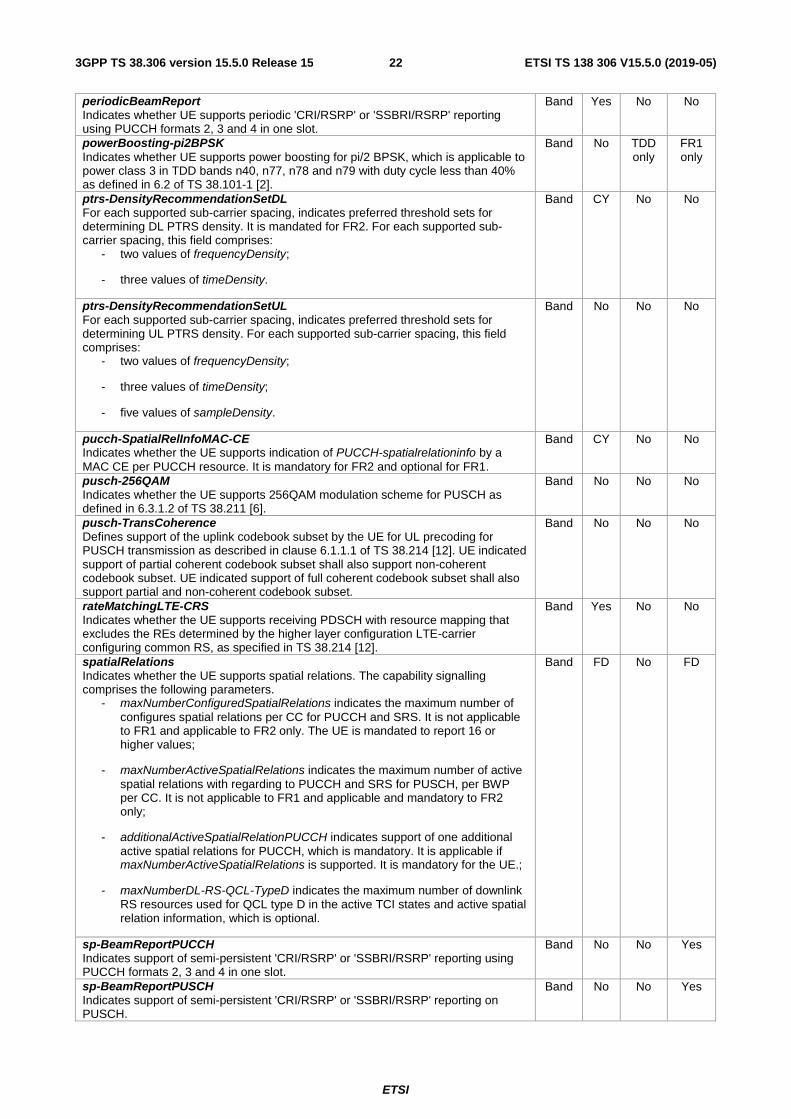
periodicBeamReport Indicates whether UE supports periodic 'CRI/RSRP' or 'SSBRI/RSRP' reporting using PUCCH formats 2, 3 and 4 in one slot.
Band Yes No No
powerBoosting-pi2BPSK Indicates whether UE supports power boosting for pi/2 BPSK, which is applicable to power class 3 in TDD bands n40, n77, n78 and n79 with duty cycle less than 40% as defined in 6.2 of TS 38.101-1 [2].
Band No TDD only
FR1 only
ptrs-DensityRecommendationSetDL For each supported sub-carrier spacing, indicates preferred threshold sets for determining DL PTRS density. It is mandated for FR2. For each supported sub-carrier spacing, this field comprises:
- two values of frequencyDensity;
- three values of timeDensity.
Band CY No No
ptrs-DensityRecommendationSetUL For each supported sub-carrier spacing, indicates preferred threshold sets for determining UL PTRS density. For each supported sub-carrier spacing, this field comprises:
- two values of frequencyDensity;
- three values of timeDensity;
- five values of sampleDensity.
Band No No No
pucch-SpatialRelInfoMAC-CE Indicates whether the UE supports indication of PUCCH-spatialrelationinfo by a MAC CE per PUCCH resource. It is mandatory for FR2 and optional for FR1.
Band CY No No
pusch-256QAM Indicates whether the UE supports 256QAM modulation scheme for PUSCH as defined in 6.3.1.2 of TS 38.211 [6].
Band No No No
pusch-TransCoherence Defines support of the uplink codebook subset by the UE for UL precoding for PUSCH transmission as described in clause 6.1.1.1 of TS 38.214 [12]. UE indicated support of partial coherent codebook subset shall also support non-coherent codebook subset. UE indicated support of full coherent codebook subset shall also support partial and non-coherent codebook subset.
Band No No No
rateMatchingLTE-CRS Indicates whether the UE supports receiving PDSCH with resource mapping that excludes the REs determined by the higher layer configuration LTE-carrier configuring common RS, as specified in TS 38.214 [12].
Band Yes No No
spatialRelations Indicates whether the UE supports spatial relations. The capability signalling comprises the following parameters.
- maxNumberConfiguredSpatialRelations indicates the maximum number of configures spatial relations per CC for PUCCH and SRS. It is not applicable to FR1 and applicable to FR2 only. The UE is mandated to report 16 or higher values;
- maxNumberActiveSpatialRelations indicates the maximum number of active spatial relations with regarding to PUCCH and SRS for PUSCH, per BWP per CC. It is not applicable to FR1 and applicable and mandatory to FR2 only;
- additionalActiveSpatialRelationPUCCH indicates support of one additional active spatial relations for PUCCH, which is mandatory. It is applicable if maxNumberActiveSpatialRelations is supported. It is mandatory for the UE.;
- maxNumberDL-RS-QCL-TypeD indicates the maximum number of downlink RS resources used for QCL type D in the active TCI states and active spatial relation information, which is optional.
Band FD No FD
sp-BeamReportPUCCH Indicates support of semi-persistent 'CRI/RSRP' or 'SSBRI/RSRP' reporting using PUCCH formats 2, 3 and 4 in one slot.
Band No No Yes
sp-BeamReportPUSCH Indicates support of semi-persistent 'CRI/RSRP' or 'SSBRI/RSRP' reporting on PUSCH.
Band No No Yes

ETSI
ETSI TS 138 306 V15.5.0 (2019-05)233GPP TS 38.306 version 15.5.0 Release 15
srs-AssocCSI-RS Parameters for the calculation of the precoder for SRS transmission based on channel measurements using associated NZP CSI-RS resource (srs-AssocCSI-RS) as described in clause 6.1.1.2 of TS 38.214 [12]. UE supporting this feature shall also indicate support of non-codebook based PUSCH transmission. This capability signalling includes list of the following parameters:
- maxNumberTxPortsPerResource indicates the maximum number of Tx ports in a resource across all CCs within a band simultaneously;
- maxNumberResourcesPerBand indicates the maximum number of resources across all CCs within a band simultaneously;
- totalNumberTxPortsPerBand indicates the total number of Tx ports across all CCs within a band simultaneously.
Band No No No
tci-StatePDSCH Defines support of TCI-States for PDSCH. The capability signalling comprises the following parameters:
- maxNumberConfiguredTCIstatesPerCC indicates the maximum number of configured TCI-states per CC for PDSCH. For FR2, the UE is mandated to set the value to 64. For FR1, the UE is mandated to set these values to the maximum number of allowed SSBs in the supported band;
- maxNumberActiveTCI-PerBWP indicates the maximum number of activated TCI-states per BWP per CC, including control and data. If a UE reports X active TCI state(s), it is not expected that more than X active QCL type D assumption(s) for any PDSCH and any CORESETs for a given BWP of a serving cell become active for the UE.
Note the UE is required to track only the active TCI states.
Band Yes No No
twoPortsPTRS-UL Defines whether UE supports PT-RS with 2 antenna ports for UL transmission.
Band No No No
ue-PowerClass For FR1, if the UE supports the different UE power class than the default UE power class as defined in clause 6.2 of TS 38.101-1 [2], the UE shall report the supported UE power class in this field. For FR2, UE shall report the supported UE power class as defined in clause 6 and 7 of TS 38.101-2 [3] in this field.
Band Yes No No
uplinkBeamManagement Defines support of beam management for UL. The capability include indication of the
- Maximum number of SRS resources per SRS resource set configurable for beam management, supported by the UE.
- Maximum number of SRS resource sets configurable for beam management, supported by the UE.
If the UE sets beamCorrespondenceWithoutUL-BeamSweeping to 0, the UE shall set this field to 1. This feature is optional for the UE supports beam correspondence without uplink beam sweeping as defined in 6.6, TS38.101-2 [3].
Band No No No
ETSI
ETSI TS 138 306 V15.5.0 (2019-05)243GPP TS 38.306 version 15.5.0 Release 15
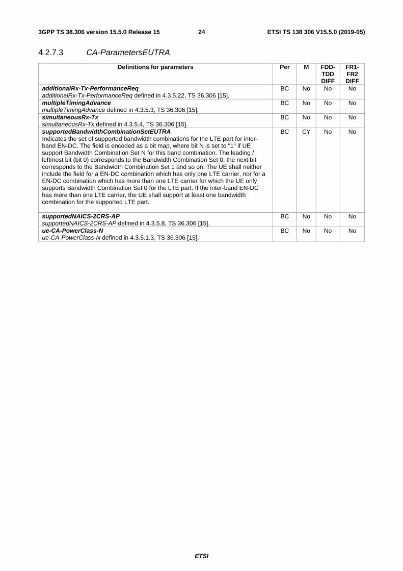
4.2.7.3 CA-ParametersEUTRA
Definitions for parameters Per M FDD-TDD DIFF
FR1-FR2 DIFF
additionalRx-Tx-PerformanceReq additionalRx-Tx-PerformanceReq defined in 4.3.5.22, TS 36.306 [15].
BC No No No
multipleTimingAdvance multipleTimingAdvance defined in 4.3.5.3, TS 36.306 [15].
BC No No No
simultaneousRx-Tx simultaneousRx-Tx defined in 4.3.5.4, TS 36.306 [15].
BC No No No
supportedBandwidthCombinationSetEUTRA Indicates the set of supported bandwidth combinations for the LTE part for inter-band EN-DC. The field is encoded as a bit map, where bit N is set to "1" if UE support Bandwidth Combination Set N for this band combination. The leading / leftmost bit (bit 0) corresponds to the Bandwidth Combination Set 0, the next bit corresponds to the Bandwidth Combination Set 1 and so on. The UE shall neither include the field for a EN-DC combination which has only one LTE carrier, nor for a EN-DC combination which has more than one LTE carrier for which the UE only supports Bandwidth Combination Set 0 for the LTE part. If the inter-band EN-DC has more than one LTE carrier, the UE shall support at least one bandwidth combination for the supported LTE part.
BC CY No No
supportedNAICS-2CRS-AP supportedNAICS-2CRS-AP defined in 4.3.5.8, TS 36.306 [15].
BC No No No
ue-CA-PowerClass-N ue-CA-PowerClass-N defined in 4.3.5.1.3, TS 36.306 [15].
BC No No No

ETSI
ETSI TS 138 306 V15.5.0 (2019-05)253GPP TS 38.306 version 15.5.0 Release 15
4.2.7.4 CA-ParametersNR
ETSI
ETSI TS 138 306 V15.5.0 (2019-05)263GPP TS 38.306 version 15.5.0 Release 15
Definitions for parameters Per M FDD-TDD DIFF
FR1-FR2 DIFF
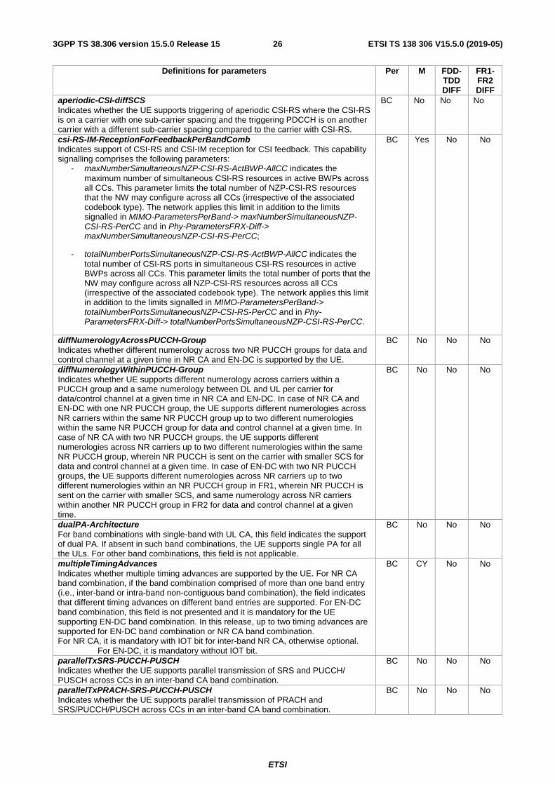
aperiodic-CSI-diffSCS Indicates whether the UE supports triggering of aperiodic CSI-RS where the CSI-RS is on a carrier with one sub-carrier spacing and the triggering PDCCH is on another carrier with a different sub-carrier spacing compared to the carrier with CSI-RS.
BC No No No
csi-RS-IM-ReceptionForFeedbackPerBandComb Indicates support of CSI-RS and CSI-IM reception for CSI feedback. This capability signalling comprises the following parameters:
- maxNumberSimultaneousNZP-CSI-RS-ActBWP-AllCC indicates the maximum number of simultaneous CSI-RS resources in active BWPs across all CCs. This parameter limits the total number of NZP-CSI-RS resources that the NW may configure across all CCs (irrespective of the associated codebook type). The network applies this limit in addition to the limits signalled in MIMO-ParametersPerBand-> maxNumberSimultaneousNZP-CSI-RS-PerCC and in Phy-ParametersFRX-Diff-> maxNumberSimultaneousNZP-CSI-RS-PerCC;
- totalNumberPortsSimultaneousNZP-CSI-RS-ActBWP-AllCC indicates the total number of CSI-RS ports in simultaneous CSI-RS resources in active BWPs across all CCs. This parameter limits the total number of ports that the NW may configure across all NZP-CSI-RS resources across all CCs (irrespective of the associated codebook type). The network applies this limit in addition to the limits signalled in MIMO-ParametersPerBand-> totalNumberPortsSimultaneousNZP-CSI-RS-PerCC and in Phy-ParametersFRX-Diff-> totalNumberPortsSimultaneousNZP-CSI-RS-PerCC.
BC Yes No No
diffNumerologyAcrossPUCCH-Group Indicates whether different numerology across two NR PUCCH groups for data and control channel at a given time in NR CA and EN-DC is supported by the UE.
BC No No No
diffNumerologyWithinPUCCH-Group Indicates whether UE supports different numerology across carriers within a PUCCH group and a same numerology between DL and UL per carrier for data/control channel at a given time in NR CA and EN-DC. In case of NR CA and EN-DC with one NR PUCCH group, the UE supports different numerologies across NR carriers within the same NR PUCCH group up to two different numerologies within the same NR PUCCH group for data and control channel at a given time. In case of NR CA with two NR PUCCH groups, the UE supports different numerologies across NR carriers up to two different numerologies within the same NR PUCCH group, wherein NR PUCCH is sent on the carrier with smaller SCS for data and control channel at a given time. In case of EN-DC with two NR PUCCH groups, the UE supports different numerologies across NR carriers up to two different numerologies within an NR PUCCH group in FR1, wherein NR PUCCH is sent on the carrier with smaller SCS, and same numerology across NR carriers within another NR PUCCH group in FR2 for data and control channel at a given time.
BC No No No
dualPA-Architecture For band combinations with single-band with UL CA, this field indicates the support of dual PA. If absent in such band combinations, the UE supports single PA for all the ULs. For other band combinations, this field is not applicable.
BC No No No
multipleTimingAdvances Indicates whether multiple timing advances are supported by the UE. For NR CA band combination, if the band combination comprised of more than one band entry (i.e., inter-band or intra-band non-contiguous band combination), the field indicates that different timing advances on different band entries are supported. For EN-DC band combination, this field is not presented and it is mandatory for the UE supporting EN-DC band combination. In this release, up to two timing advances are supported for EN-DC band combination or NR CA band combination. For NR CA, it is mandatory with IOT bit for inter-band NR CA, otherwise optional.
For EN-DC, it is mandatory without IOT bit.
BC CY No No
parallelTxSRS-PUCCH-PUSCH Indicates whether the UE supports parallel transmission of SRS and PUCCH/ PUSCH across CCs in an inter-band CA band combination.
BC No No No
parallelTxPRACH-SRS-PUCCH-PUSCH Indicates whether the UE supports parallel transmission of PRACH and SRS/PUCCH/PUSCH across CCs in an inter-band CA band combination.
BC No No No
ETSI
ETSI TS 138 306 V15.5.0 (2019-05)273GPP TS 38.306 version 15.5.0 Release 15
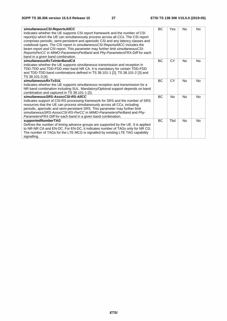
simultaneousCSI-ReportsAllCC Indicates whether the UE supports CSI report framework and the number of CSI report(s) which the UE can simultaneously process across all CCs. The CSI report comprises periodic, semi-persistent and aperiodic CSI and any latency classes and codebook types. The CSI report in simultaneousCSI-ReportsAllCC includes the beam report and CSI report. This parameter may further limit simultaneousCSI-ReportsPerCC in MIMO-ParametersPerBand and Phy-ParametersFRX-Diff for each band in a given band combination.
BC Yes No No
simultaneousRxTxInterBandCA Indicates whether the UE supports simultaneous transmission and reception in TDD-TDD and TDD-FDD inter-band NR CA. It is mandatory for certain TDD-FDD and TDD-TDD band combinations defined in TS 38.101-1 [2], TS 38.101-2 [3] and TS 38.101-3 [4].
BC CY No No
simultaneousRxTxSUL Indicates whether the UE supports simultaneous reception and transmission for a NR band combination including SUL. Mandatory/Optional support depends on band combination and captured in TS 38.101-1 [2].
BC CY No No
simultaneousSRS-AssocCSI-RS-AllCC Indicates support of CSI-RS processing framework for SRS and the number of SRS resources that the UE can process simultaneously across all CCs, including periodic, aperiodic and semi-persistent SRS. This parameter may further limit simultaneousSRS-AssocCSI-RS-PerCC in MIMO-ParametersPerBand and Phy-ParametersFRX-Diff for each band in a given band combination.
BC No No No
supportedNumberTAG Defines the number of timing advance groups are supported by the UE. It is applied to NR-NR CA and EN-DC. For EN-DC, it indicates number of TAGs only for NR CG. The number of TAGs for the LTE MCG is signalled by existing LTE TAG capability signalling.
BC Tbd No No

ETSI
ETSI TS 138 306 V15.5.0 (2019-05)283GPP TS 38.306 version 15.5.0 Release 15
4.2.7.5 FeatureSetDownlink parameters
ETSI
ETSI TS 138 306 V15.5.0 (2019-05)293GPP TS 38.306 version 15.5.0 Release 15
Definitions for parameters Per M FDD-TDD DIFF
FR1-FR2 DIFF
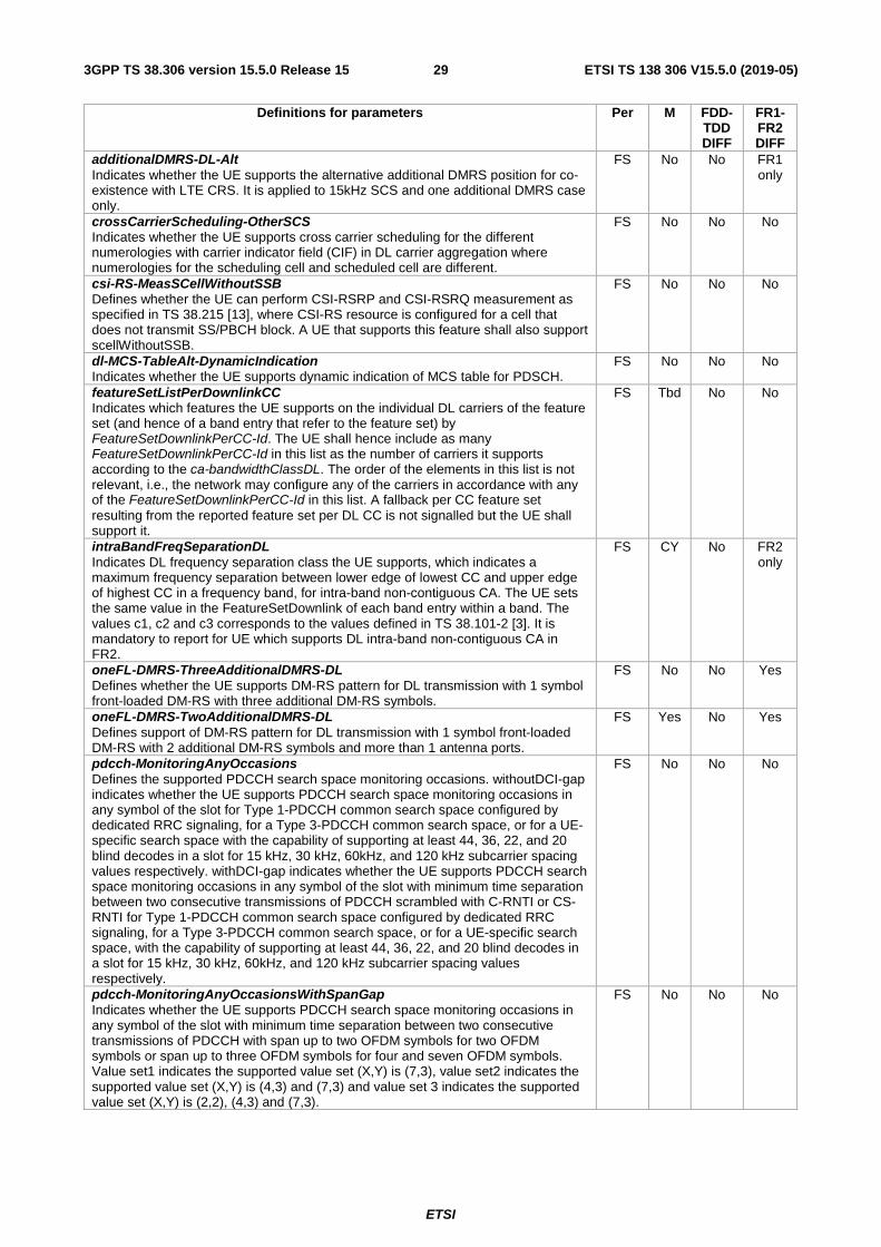
additionalDMRS-DL-Alt Indicates whether the UE supports the alternative additional DMRS position for co-existence with LTE CRS. It is applied to 15kHz SCS and one additional DMRS case only.
FS No No FR1 only
crossCarrierScheduling-OtherSCS Indicates whether the UE supports cross carrier scheduling for the different numerologies with carrier indicator field (CIF) in DL carrier aggregation where numerologies for the scheduling cell and scheduled cell are different.
FS No No No
csi-RS-MeasSCellWithoutSSB Defines whether the UE can perform CSI-RSRP and CSI-RSRQ measurement as specified in TS 38.215 [13], where CSI-RS resource is configured for a cell that does not transmit SS/PBCH block. A UE that supports this feature shall also support scellWithoutSSB.
FS No No No
dl-MCS-TableAlt-DynamicIndication Indicates whether the UE supports dynamic indication of MCS table for PDSCH.
FS No No No
featureSetListPerDownlinkCC Indicates which features the UE supports on the individual DL carriers of the feature set (and hence of a band entry that refer to the feature set) by FeatureSetDownlinkPerCC-Id. The UE shall hence include as many FeatureSetDownlinkPerCC-Id in this list as the number of carriers it supports according to the ca-bandwidthClassDL. The order of the elements in this list is not relevant, i.e., the network may configure any of the carriers in accordance with any of the FeatureSetDownlinkPerCC-Id in this list. A fallback per CC feature set resulting from the reported feature set per DL CC is not signalled but the UE shall support it.
FS Tbd No No
intraBandFreqSeparationDL Indicates DL frequency separation class the UE supports, which indicates a maximum frequency separation between lower edge of lowest CC and upper edge of highest CC in a frequency band, for intra-band non-contiguous CA. The UE sets the same value in the FeatureSetDownlink of each band entry within a band. The values c1, c2 and c3 corresponds to the values defined in TS 38.101-2 [3]. It is mandatory to report for UE which supports DL intra-band non-contiguous CA in FR2.
FS CY No FR2 only
oneFL-DMRS-ThreeAdditionalDMRS-DL Defines whether the UE supports DM-RS pattern for DL transmission with 1 symbol front-loaded DM-RS with three additional DM-RS symbols.
FS No No Yes
oneFL-DMRS-TwoAdditionalDMRS-DL Defines support of DM-RS pattern for DL transmission with 1 symbol front-loaded DM-RS with 2 additional DM-RS symbols and more than 1 antenna ports.
FS Yes No Yes
pdcch-MonitoringAnyOccasions Defines the supported PDCCH search space monitoring occasions. withoutDCI-gap indicates whether the UE supports PDCCH search space monitoring occasions in any symbol of the slot for Type 1-PDCCH common search space configured by dedicated RRC signaling, for a Type 3-PDCCH common search space, or for a UE-specific search space with the capability of supporting at least 44, 36, 22, and 20 blind decodes in a slot for 15 kHz, 30 kHz, 60kHz, and 120 kHz subcarrier spacing values respectively. withDCI-gap indicates whether the UE supports PDCCH search space monitoring occasions in any symbol of the slot with minimum time separation between two consecutive transmissions of PDCCH scrambled with C-RNTI or CS-RNTI for Type 1-PDCCH common search space configured by dedicated RRC signaling, for a Type 3-PDCCH common search space, or for a UE-specific search space, with the capability of supporting at least 44, 36, 22, and 20 blind decodes in a slot for 15 kHz, 30 kHz, 60kHz, and 120 kHz subcarrier spacing values respectively.
FS No No No
pdcch-MonitoringAnyOccasionsWithSpanGap Indicates whether the UE supports PDCCH search space monitoring occasions in any symbol of the slot with minimum time separation between two consecutive transmissions of PDCCH with span up to two OFDM symbols for two OFDM symbols or span up to three OFDM symbols for four and seven OFDM symbols. Value set1 indicates the supported value set (X,Y) is (7,3), value set2 indicates the supported value set (X,Y) is (4,3) and (7,3) and value set 3 indicates the supported value set (X,Y) is (2,2), (4,3) and (7,3).
FS No No No

ETSI
ETSI TS 138 306 V15.5.0 (2019-05)303GPP TS 38.306 version 15.5.0 Release 15
pdsch-ProcessingType1-DifferentTB-PerSlot Defines whether the UE capable of processing time capability 1 supports reception of up to two, four or seven PDSCHs for several transport blocks with PDSCH scrambled using C-RNTI, TC-RNTI, or CS-RNTI in each of the applicable DL CCs within the same slot only in TDM. Note PDSCH(s) for Msg.4 is included.
FS No No No
pdsch-ProcessingType2 Indicates whether the UE supports PDSCH processing capability 2. The UE supports it only if all serving cells are self-scheduled and if all serving cells in one band on which the network configured processingType2 use the same subcarrier spacing. This capability signalling comprises the following parameters for each sub-carrier spacing supported by the UE.
- fallback indicates whether the UE supports PDSCH processing capability 2 when the number of configured carriers is larger than numberOfCarriers for a reported value of differentTB-PerSlot. If fallback = 'sc', UE supports capability 2 processing time on lowest cell index among the configured carriers in the band where the value is reported, if fallback = 'cap1-only', UE supports only capability 1, in the band where the value is reported;
- differentTB-PerSlot indicates whether the UE supports processing type 2 for 1, 2, 4 and/or 7 transport blocks per slot; and if so, it indicates up to which number of CA serving cells the UE supports that number of TBs.
FS No No FR1 only
pdsch-ProcessingType2-Limited Indicates whether the UE supports PDSCH processing capability 2 with scheduling limitation for SCS 30kHz. This capability signalling comprises the following parameter.
- differentTB-PerSlot-SCS-30kHz indicates the number of different TBs per slot.
The UE supports this limited processing capability 2 only if: 1) One carrier is configured in the band, independent of the number of carriers
configured in the other bands;
2) The maximum bandwidth of PDSCH is 136 PRBs;
3) N1 based on Table 5.3-2 of TS 38.214 [12] for SCS 30 kHz.
FS No No FR1 only
pdsch-SeparationWithGap Indicates whether the UE supports separation of two unicast PDSCHs with a gap, applicable to Sub-carrier spacings of 30 KHz and 60 KHz only. For any two consecutive slots n and n+1, if there are more than 1 unicast PDSCH in either slot, the minimum time separation between starting time of any two unicast PDSCHs within the duration of these slots is 4 OFDM symbol for 30kHz and 7 OFDM symbol for 60kHz.
FS No No No
scalingFactor Indicates the scaling factor to be applied to the band in the max data rate calculation as defined in 4.1.2. Value f0p4 indicates the scaling factor 0.4, f0p75 indicates 0.75, and so on. If absent, the scaling factor 1 is applied to the band in the max data rate calculation.
FS Tbd No No
scellWithoutSSB Defines whether the UE supports configuration of SCell that does not transmit SS/PBCH block. This is conditionally mandatory with capability signalling for intra-band CA but not supported for inter-band CA.
FS CY No No
searchSpaceSharingCA-DL Defines whether the UE supports DL PDCCH search space sharing for carrier aggregation operation.
FS No No No
timeDurationForQCL Defines minimum number of OFDM symbols required by the UE to perform PDCCH reception and applying spatial QCL information received in DCI for PDSCH processing as described in TS 38.214 [12] clause 5.1.5, i.e. Threshold-Sched-Offset. UE shall indicate one value of the minimum number of OFDM symbols per each subcarrier spacing of 60kHz and 120kHz.
FS Yes No FR2 only
twoFL-DMRS-TwoAdditionalDMRS-DL Defines whether the UE supports DM-RS pattern for DL transmission with 2 symbols front-loaded DM-RS with one additional 2 symbols DM-RS.
FS No No Yes
ETSI
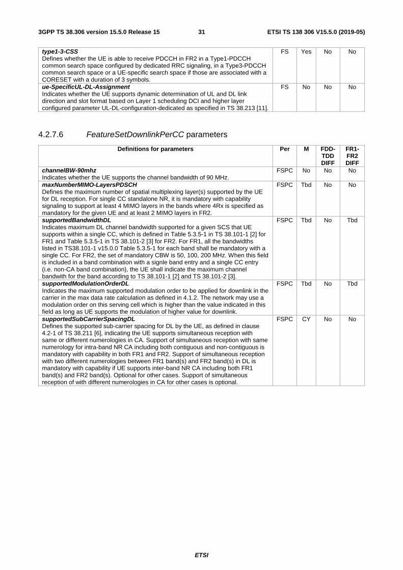
ETSI TS 138 306 V15.5.0 (2019-05)313GPP TS 38.306 version 15.5.0 Release 15
type1-3-CSS Defines whether the UE is able to receive PDCCH in FR2 in a Type1-PDCCH common search space configured by dedicated RRC signaling, in a Type3-PDCCH common search space or a UE-specific search space if those are associated with a CORESET with a duration of 3 symbols.
FS Yes No No
ue-SpecificUL-DL-Assignment Indicates whether the UE supports dynamic determination of UL and DL link direction and slot format based on Layer 1 scheduling DCI and higher layer configured parameter UL-DL-configuration-dedicated as specified in TS 38.213 [11].
FS No No No
4.2.7.6 FeatureSetDownlinkPerCC parameters
Definitions for parameters Per M FDD-TDD DIFF
FR1-FR2 DIFF
channelBW-90mhz Indicates whether the UE supports the channel bandwidth of 90 MHz.
FSPC No No No
maxNumberMIMO-LayersPDSCH Defines the maximum number of spatial multiplexing layer(s) supported by the UE for DL reception. For single CC standalone NR, it is mandatory with capability signaling to support at least 4 MIMO layers in the bands where 4Rx is specified as mandatory for the given UE and at least 2 MIMO layers in FR2.
FSPC Tbd No No
supportedBandwidthDL Indicates maximum DL channel bandwidth supported for a given SCS that UE supports within a single CC, which is defined in Table 5.3.5-1 in TS 38.101-1 [2] for FR1 and Table 5.3.5-1 in TS 38.101-2 [3] for FR2. For FR1, all the bandwidths listed in TS38.101-1 v15.0.0 Table 5.3.5-1 for each band shall be mandatory with a single CC. For FR2, the set of mandatory CBW is 50, 100, 200 MHz. When this field is included in a band combination with a signle band entry and a single CC entry (i.e. non-CA band combination), the UE shall indicate the maximum channel bandwith for the band according to TS 38.101-1 [2] and TS 38.101-2 [3].
FSPC Tbd No Tbd
supportedModulationOrderDL Indicates the maximum supported modulation order to be applied for downlink in the carrier in the max data rate calculation as defined in 4.1.2. The network may use a modulation order on this serving cell which is higher than the value indicated in this field as long as UE supports the modulation of higher value for downlink.
FSPC Tbd No Tbd
supportedSubCarrierSpacingDL Defines the supported sub-carrier spacing for DL by the UE, as defined in clause 4.2-1 of TS 38.211 [6], indicating the UE supports simultaneous reception with same or different numerologies in CA. Support of simultaneous reception with same numerology for intra-band NR CA including both contiguous and non-contiguous is mandatory with capability in both FR1 and FR2. Support of simultaneous reception with two different numerologies between FR1 band(s) and FR2 band(s) in DL is mandatory with capability if UE supports inter-band NR CA including both FR1 band(s) and FR2 band(s). Optional for other cases. Support of simultaneous reception of with different numerologies in CA for other cases is optional.
FSPC CY No No

ETSI
ETSI TS 138 306 V15.5.0 (2019-05)323GPP TS 38.306 version 15.5.0 Release 15
4.2.7.7 FeatureSetUplink parameters

ETSI
ETSI TS 138 306 V15.5.0 (2019-05)333GPP TS 38.306 version 15.5.0 Release 15
Definitions for parameters Per M FDD-TDD DIFF
FR1-FR2 DIFF
scalingFactor Indicates the scaling factor to be applied to the band in the max data rate calculation as defined in 4.1.2. Value f0p4 indicates the scaling factor 0.4, f0p75 indicates 0.75, and so on. If absent, the scaling factor 1 is applied to the band in the max data rate calculation.
FS Tbd No No
crossCarrierScheduling-OtherSCS Indicates whether the UE supports cross carrier scheduling for the different numerologies with carrier indicator field (CIF) in UL carrier aggregation where numerologies for the scheduling cell and scheduled cell are different. The UE shall set this field to the same value as crossCarrierScheduling-OtherSCS in the associated FeatureSetDownlink (if present).
FS No No No
dynamicSwitchSUL Indicates whether the UE supports supplemental uplink with dynamic switch (DCI based selection of PUSCH carrier).
FS No No No
featureSetListPerUplinkCC Indicates which features the UE supports on the individual UL carriers of the feature set (and hence of a band entry that refer to the feature set) by FeatureSetUplinkPerCC-Id. The UE shall hence include as many FeatureSetUplinkPerCC-Id in this list as the number of carriers it supports according to the ca-bandwidthClassUL. The order of the elements in this list is not relevant, i.e., the network may configure any of the carriers in accordance with any of the FeatureSetUplinkPerCC-Id in this list. A fallback per CC feature set resulting from the reported feature set per UL CC is not signalled but the UE shall support it.
FS Tbd No No
intraBandFreqSeparationUL Indicates UL frequency separation class the UE supports, which indicates a maximum frequency separation between lower edge of lowest CC and upper edge of highest CC in a frequency band, for intra-band non-contiguous CA. The UE sets the same value in the FeatureSetUplink of each band entry within a band. The values c1, c2 and c3 corresponds to the values defined in TS 38.101-2 [3]. It is mandatory to report for UE which supports UL non-contiguous CA in FR2.
FS CY No FR2 only
pa-PhaseDiscontinuityImpacts Indicates incapability motivated by impacts of PA phase discontinuity with overlapping transmissions with non-aligned starting or ending times or hop boundaries across carriers for intra-band EN-DC, intra-band CA and FDM based ULSUP.
FS No No No
pusch-ProcessingType1-DifferentTB-PerSlot Indicates whether the UE capable of processing time capability 1 supports transmission of up to two, four or seven PUSCHs for several transport blocks in each of the applicable UL CCs within the same slot only in TDM.
FS No No No
pusch-ProcessingType2 Indicates whether the UE supports PUSCH processing capability 2. The UE supports it only if all serving cells are self-scheduled and if all serving cells in one band on which the network configured processingType2 use the same subcarrier spacing. This capability signalling comprises the following parameters for each sub-carrier spacing supported by the UE.
- fallback indicates whether the UE supports PUSCH processing capability 2 when the number of configured carriers is larger than numberOfCarriers for a reported value of differentTB-PerSlot. If fallback = 'sc', UE supports capability 2 processing time on lowest cell index among the configured carriers in the band where the value is reported, if fallback = 'cap1-only', UE supports only capability 1, in the band where the value is reported;
- differentTB-PerSlot indicates whether the UE supports processing type 2 for 1, 2, 4 and/or 7 transport blocks per slot; and if so, it indicates up to which number of CA serving cells the UE supports that number of TBs.
FS No No FR1 only
pusch-SeparationWithGap Indicates whether the UE supports separation of two unicast PUSCHs with a gap, applicable to Sub-carrier spacings of 15 KHz, 30 KHz and 60 KHz only. For any two consecutive slots n and n+1, if there are more than 1 unicast PUSCH in either slot, the minimum time separation between starting time of any two unicast PUSCHs within the duration of these slots is 2 OFDM symbols for 15kHz, 4 OFDM symbols for 30kHz and 7 OFDM symbols for 60kHz.
FS No No No
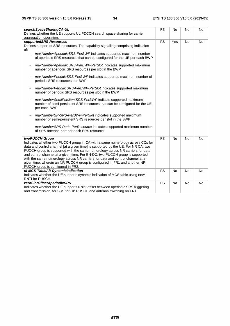
ETSI
ETSI TS 138 306 V15.5.0 (2019-05)343GPP TS 38.306 version 15.5.0 Release 15
searchSpaceSharingCA-UL Defines whether the UE supports UL PDCCH search space sharing for carrier aggregation operation.
FS No No No
supportedSRS-Resources Defines support of SRS resources. The capability signalling comprising indication of:
- maxNumberAperiodicSRS-PerBWP indicates supported maximum number of aperiodic SRS resources that can be configured for the UE per each BWP
- maxNumberAperiodicSRS-PerBWP-PerSlot indicates supported maximum number of aperiodic SRS resources per slot in the BWP
- maxNumberPeriodicSRS-PerBWP indicates supported maximum number of periodic SRS resources per BWP
- maxNumberPeriodicSRS-PerBWP-PerSlot indicates supported maximum number of periodic SRS resources per slot in the BWP
- maxNumberSemiPersitentSRS-PerBWP indicate supported maximum number of semi-persistent SRS resources that can be configured for the UE per each BWP
- maxNumberSP-SRS-PerBWP-PerSlot indicates supported maximum number of semi-persistent SRS resources per slot in the BWP
- maxNumberSRS-Ports-PerResource indicates supported maximum number of SRS antenna port per each SRS resource
FS Yes No No
twoPUCCH-Group Indicates whether two PUCCH group in CA with a same numerology across CCs for data and control channel [at a given time] is supported by the UE. For NR CA, two PUCCH group is supported with the same numerology across NR carriers for data and control channel at a given time. For EN-DC, two PUCCH group is supported with the same numerology across NR carriers for data and control channel at a given time, wherein an NR PUCCH group is configured in FR1 and another NR PUCCH group is configured in FR2.
FS No No No
ul-MCS-TableAlt-DynamicIndication Indicates whether the UE supports dynamic indication of MCS table using new RNTI for PUSCH.
FS No No No
zeroSlotOffsetAperiodicSRS Indicates whether the UE supports 0 slot offset between aperiodic SRS triggering and transmission, for SRS for CB PUSCH and antenna switching on FR1.
FS No No No
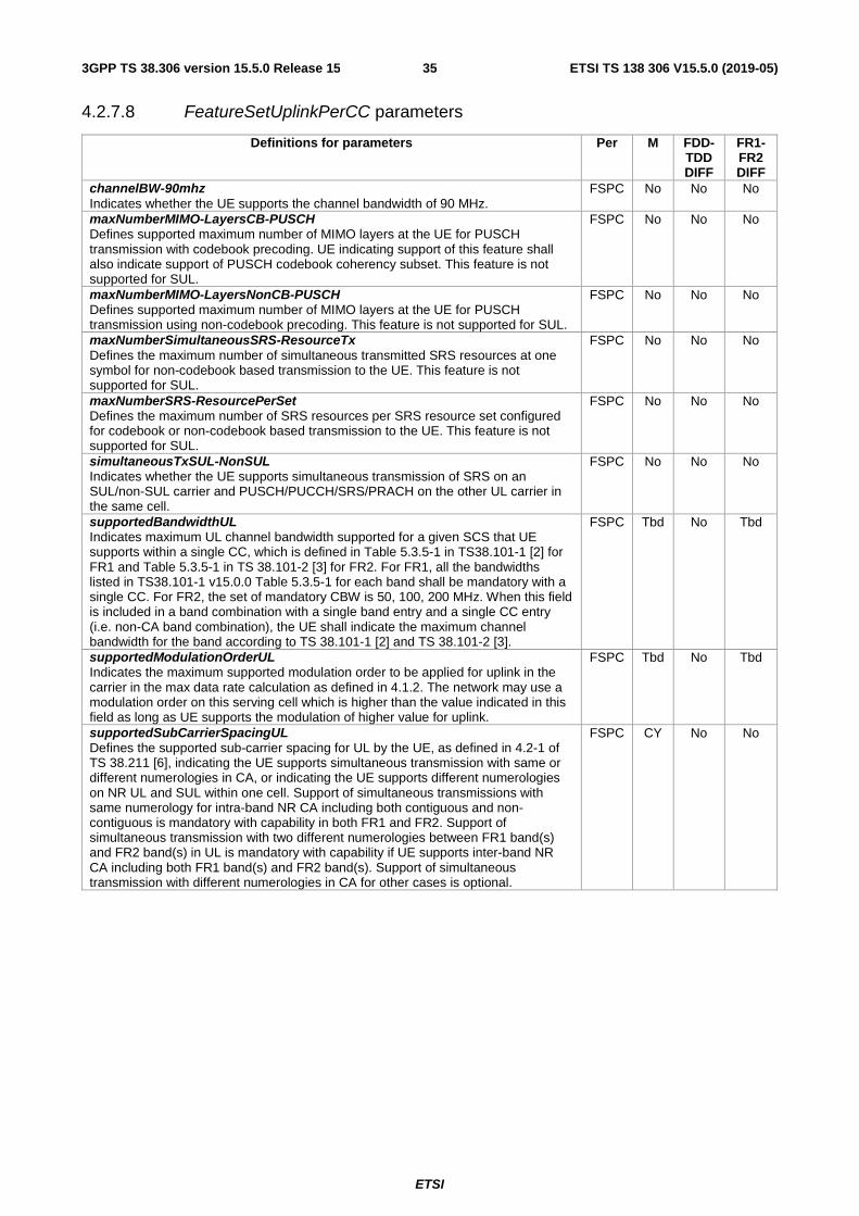
ETSI
ETSI TS 138 306 V15.5.0 (2019-05)353GPP TS 38.306 version 15.5.0 Release 15
4.2.7.8 FeatureSetUplinkPerCC parameters
Definitions for parameters Per M FDD-TDD DIFF
FR1-FR2 DIFF
channelBW-90mhz Indicates whether the UE supports the channel bandwidth of 90 MHz.
FSPC No No No
maxNumberMIMO-LayersCB-PUSCH Defines supported maximum number of MIMO layers at the UE for PUSCH transmission with codebook precoding. UE indicating support of this feature shall also indicate support of PUSCH codebook coherency subset. This feature is not supported for SUL.
FSPC No No No
maxNumberMIMO-LayersNonCB-PUSCH Defines supported maximum number of MIMO layers at the UE for PUSCH transmission using non-codebook precoding. This feature is not supported for SUL.
FSPC No No No
maxNumberSimultaneousSRS-ResourceTx Defines the maximum number of simultaneous transmitted SRS resources at one symbol for non-codebook based transmission to the UE. This feature is not supported for SUL.
FSPC No No No
maxNumberSRS-ResourcePerSet Defines the maximum number of SRS resources per SRS resource set configured for codebook or non-codebook based transmission to the UE. This feature is not supported for SUL.
FSPC No No No
simultaneousTxSUL-NonSUL Indicates whether the UE supports simultaneous transmission of SRS on an SUL/non-SUL carrier and PUSCH/PUCCH/SRS/PRACH on the other UL carrier in the same cell.
FSPC No No No
supportedBandwidthUL Indicates maximum UL channel bandwidth supported for a given SCS that UE supports within a single CC, which is defined in Table 5.3.5-1 in TS38.101-1 [2] for FR1 and Table 5.3.5-1 in TS 38.101-2 [3] for FR2. For FR1, all the bandwidths listed in TS38.101-1 v15.0.0 Table 5.3.5-1 for each band shall be mandatory with a single CC. For FR2, the set of mandatory CBW is 50, 100, 200 MHz. When this field is included in a band combination with a single band entry and a single CC entry (i.e. non-CA band combination), the UE shall indicate the maximum channel bandwidth for the band according to TS 38.101-1 [2] and TS 38.101-2 [3].
FSPC Tbd No Tbd
supportedModulationOrderUL Indicates the maximum supported modulation order to be applied for uplink in the carrier in the max data rate calculation as defined in 4.1.2. The network may use a modulation order on this serving cell which is higher than the value indicated in this field as long as UE supports the modulation of higher value for uplink.
FSPC Tbd No Tbd
supportedSubCarrierSpacingUL Defines the supported sub-carrier spacing for UL by the UE, as defined in 4.2-1 of TS 38.211 [6], indicating the UE supports simultaneous transmission with same or different numerologies in CA, or indicating the UE supports different numerologies on NR UL and SUL within one cell. Support of simultaneous transmissions with same numerology for intra-band NR CA including both contiguous and non-contiguous is mandatory with capability in both FR1 and FR2. Support of simultaneous transmission with two different numerologies between FR1 band(s) and FR2 band(s) in UL is mandatory with capability if UE supports inter-band NR CA including both FR1 band(s) and FR2 band(s). Support of simultaneous transmission with different numerologies in CA for other cases is optional.
FSPC CY No No
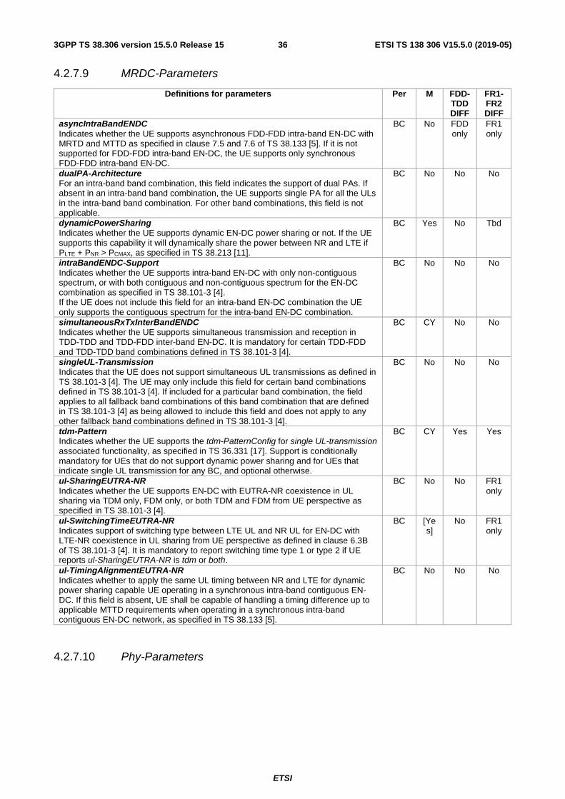
ETSI
ETSI TS 138 306 V15.5.0 (2019-05)363GPP TS 38.306 version 15.5.0 Release 15
4.2.7.9 MRDC-Parameters
Definitions for parameters Per M FDD-TDD DIFF
FR1-FR2 DIFF
asyncIntraBandENDC Indicates whether the UE supports asynchronous FDD-FDD intra-band EN-DC with MRTD and MTTD as specified in clause 7.5 and 7.6 of TS 38.133 [5]. If it is not supported for FDD-FDD intra-band EN-DC, the UE supports only synchronous FDD-FDD intra-band EN-DC.
BC No FDD only
FR1 only
dualPA-Architecture For an intra-band band combination, this field indicates the support of dual PAs. If absent in an intra-band band combination, the UE supports single PA for all the ULs in the intra-band band combination. For other band combinations, this field is not applicable.
BC No No No
dynamicPowerSharing Indicates whether the UE supports dynamic EN-DC power sharing or not. If the UE supports this capability it will dynamically share the power between NR and LTE if PLTE + PNR > PCMAX, as specified in TS 38.213 [11].
BC Yes No Tbd
intraBandENDC-Support Indicates whether the UE supports intra-band EN-DC with only non-contiguous spectrum, or with both contiguous and non-contiguous spectrum for the EN-DC combination as specified in TS 38.101-3 [4]. If the UE does not include this field for an intra-band EN-DC combination the UE only supports the contiguous spectrum for the intra-band EN-DC combination.
BC No No No
simultaneousRxTxInterBandENDC Indicates whether the UE supports simultaneous transmission and reception in TDD-TDD and TDD-FDD inter-band EN-DC. It is mandatory for certain TDD-FDD and TDD-TDD band combinations defined in TS 38.101-3 [4].
BC CY No No
singleUL-Transmission Indicates that the UE does not support simultaneous UL transmissions as defined in TS 38.101-3 [4]. The UE may only include this field for certain band combinations defined in TS 38.101-3 [4]. If included for a particular band combination, the field applies to all fallback band combinations of this band combination that are defined in TS 38.101-3 [4] as being allowed to include this field and does not apply to any other fallback band combinations defined in TS 38.101-3 [4].
BC No No No
tdm-Pattern Indicates whether the UE supports the tdm-PatternConfig for single UL-transmission associated functionality, as specified in TS 36.331 [17]. Support is conditionally mandatory for UEs that do not support dynamic power sharing and for UEs that indicate single UL transmission for any BC, and optional otherwise.
BC CY Yes Yes
ul-SharingEUTRA-NR Indicates whether the UE supports EN-DC with EUTRA-NR coexistence in UL sharing via TDM only, FDM only, or both TDM and FDM from UE perspective as specified in TS 38.101-3 [4].
BC No No FR1 only
ul-SwitchingTimeEUTRA-NR Indicates support of switching type between LTE UL and NR UL for EN-DC with LTE-NR coexistence in UL sharing from UE perspective as defined in clause 6.3B of TS 38.101-3 [4]. It is mandatory to report switching time type 1 or type 2 if UE reports ul-SharingEUTRA-NR is tdm or both.
BC [Yes]
No FR1 only
ul-TimingAlignmentEUTRA-NR Indicates whether to apply the same UL timing between NR and LTE for dynamic power sharing capable UE operating in a synchronous intra-band contiguous EN-DC. If this field is absent, UE shall be capable of handling a timing difference up to applicable MTTD requirements when operating in a synchronous intra-band contiguous EN-DC network, as specified in TS 38.133 [5].
BC No No No
4.2.7.10 Phy-Parameters

ETSI
ETSI TS 138 306 V15.5.0 (2019-05)373GPP TS 38.306 version 15.5.0 Release 15
Definitions for parameters Per M FDD-TDD DIFF
FR1-FR2 DIFF
absoluteTPC-Command Indicates whether the UE supports absolute TPC command mode.
UE No No Yes
almostContiguousCP-OFDM-UL Indicates whether the UE supports almost contiguous UL CP-OFDM transmissions as defined in clause 6.2 of TS 38.101-1 [2].
UE No No Yes
bwp-SwitchingDelay Defines whether the UE supports DCI and timer based active BWP switching delay type1 or type2 specified in clause 8.6.2 of TS 38.133 [5]. It is mandatory to report type 1 or type 2.
UE Yes No No
cbg-FlushIndication-DL Indicates whether the UE supports CBG-based (re)transmission for DL using CBG flushing out information (CBGFI) as specified in TS 38.214 [12].
UE No No No
cbg-TransIndication-DL Indicates whether the UE supports CBG-based (re)transmission for DL using CBG transmission information (CBGTI) as specified in TS 38.214 [12].
UE No No No
cbg-TransIndication-UL Indicates whether the UE supports CBG-based (re)transmission for UL using CBG transmission information (CBGTI) as specified in TS 38.214 [12].
UE No No No
configuredUL-GrantType1 Indicates whether the UE supports Type 1 PUSCH transmissions with configured grant as specified in TS 38.214 [12] with UL-TWG-repK value of one.
UE No No No
configuredUL-GrantType2 Indicates whether the UE supports Type 2 PUSCH transmissions with configured grant as specified in TS 38.214 [12] with UL-TWG-repK value of one.
UE No No No
cqi-TableAlt Indicates whether UE supports the CQI table with target BLER of 10^-5.
UE No No Yes
csi-ReportFramework See csi-ReportFramework in 4.2.7.2. For a band combination comprised of FR1 and FR2 bands, this parameter, if present, limits the corresponding parameter in MIMO-ParametersPerBand.
Band or UE
Yes No No
csi-ReportWithoutCQI Indicates whether UE supports CSI reporting with report quantity set to 'CRI/RI/i1' as defined in clause 5.2.1.4 of TS 38.214 [12].
UE No No Yes
csi-ReportWithoutPMI Indicates whether UE supports CSI reporting with report quantity set to 'CRI/RI/CQI' as defined in clause 5.2.1.4 of TS 38.214 [12].
UE No No Yes
csi-RS-CFRA-ForHO Indicates whether the UE can perform handover using a contention free random access on PRACH resources that are associated with CSI-RS resources of the target cell.
UE No No No
csi-RS-IM-ReceptionForFeedback See csi-RS-IM-ReceptionForFeedback in 4.2.7.2. For a band combination comprised of FR1 and FR2 bands, this parameter, if present, limits the corresponding parameter in MIMO-ParametersPerBand.
Band or UE
Yes No No
csi-RS-ProcFrameworkForSRS See csi-RS-ProcFrameworkForSRS in 4.2.7.2. For a band combination comprised of FR1 and FR2 bands, this parameter, if present, limits the corresponding parameter in MIMO-ParametersPerBand.
Band or UE
No No No
dl-64QAM-MCS-TableAlt Indicates whether the UE supports the alternative 64QAM MCS table for PDSCH.
UE No No Yes
dl-SchedulingOffset-PDSCH-TypeA Indicates whether the UE supports DL scheduling slot offset (K0) greater than 0 for PDSCH mapping type A.
UE Yes Yes Yes
dl-SchedulingOffset-PDSCH-TypeB Indicates whether the UE supports DL scheduling slot offset (K0) greater than 0 for PDSCH mapping type B.
UE Yes Yes Yes
downlinkSPS Indicates whether the UE supports PDSCH reception based on semi-persistent scheduling.
UE No No No
dynamicBetaOffsetInd-HARQ-ACK-CSI Indicates whether the UE supports indicating beta-offset (UCI repetition factor onto PUSCH) for HARQ-ACK and/or SR via DCI among the RRC configured beta-offsets.
UE No No No
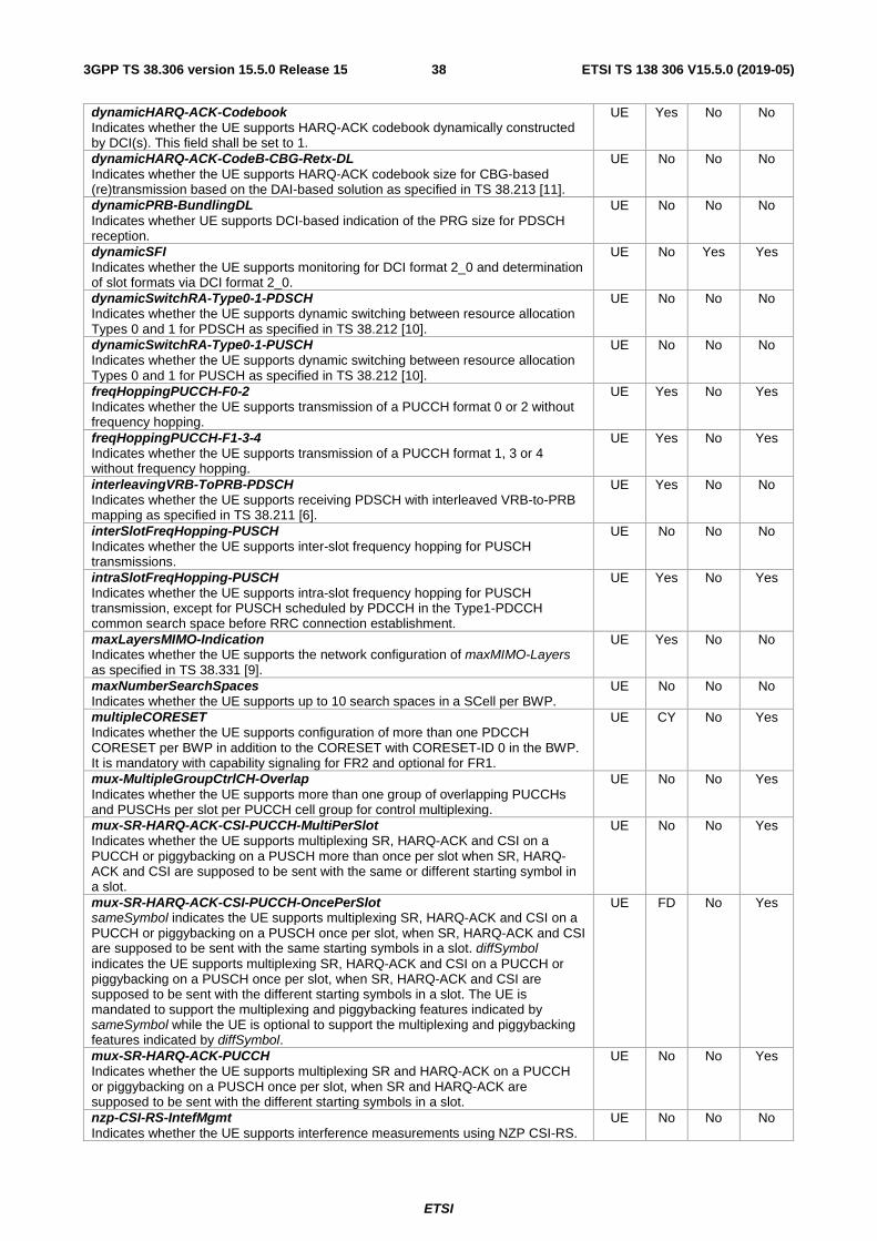
ETSI
ETSI TS 138 306 V15.5.0 (2019-05)383GPP TS 38.306 version 15.5.0 Release 15
dynamicHARQ-ACK-Codebook Indicates whether the UE supports HARQ-ACK codebook dynamically constructed by DCI(s). This field shall be set to 1.
UE Yes No No
dynamicHARQ-ACK-CodeB-CBG-Retx-DL Indicates whether the UE supports HARQ-ACK codebook size for CBG-based (re)transmission based on the DAI-based solution as specified in TS 38.213 [11].
UE No No No
dynamicPRB-BundlingDL Indicates whether UE supports DCI-based indication of the PRG size for PDSCH reception.
UE No No No
dynamicSFI Indicates whether the UE supports monitoring for DCI format 2_0 and determination of slot formats via DCI format 2_0.
UE No Yes Yes
dynamicSwitchRA-Type0-1-PDSCH Indicates whether the UE supports dynamic switching between resource allocation Types 0 and 1 for PDSCH as specified in TS 38.212 [10].
UE No No No
dynamicSwitchRA-Type0-1-PUSCH Indicates whether the UE supports dynamic switching between resource allocation Types 0 and 1 for PUSCH as specified in TS 38.212 [10].
UE No No No
freqHoppingPUCCH-F0-2 Indicates whether the UE supports transmission of a PUCCH format 0 or 2 without frequency hopping.
UE Yes No Yes
freqHoppingPUCCH-F1-3-4 Indicates whether the UE supports transmission of a PUCCH format 1, 3 or 4 without frequency hopping.
UE Yes No Yes
interleavingVRB-ToPRB-PDSCH Indicates whether the UE supports receiving PDSCH with interleaved VRB-to-PRB mapping as specified in TS 38.211 [6].
UE Yes No No
interSlotFreqHopping-PUSCH Indicates whether the UE supports inter-slot frequency hopping for PUSCH transmissions.
UE No No No
intraSlotFreqHopping-PUSCH Indicates whether the UE supports intra-slot frequency hopping for PUSCH transmission, except for PUSCH scheduled by PDCCH in the Type1-PDCCH common search space before RRC connection establishment.
UE Yes No Yes
maxLayersMIMO-Indication Indicates whether the UE supports the network configuration of maxMIMO-Layers as specified in TS 38.331 [9].
UE Yes No No
maxNumberSearchSpaces Indicates whether the UE supports up to 10 search spaces in a SCell per BWP.
UE No No No
multipleCORESET Indicates whether the UE supports configuration of more than one PDCCH CORESET per BWP in addition to the CORESET with CORESET-ID 0 in the BWP. It is mandatory with capability signaling for FR2 and optional for FR1.
UE CY No Yes
mux-MultipleGroupCtrlCH-Overlap Indicates whether the UE supports more than one group of overlapping PUCCHs and PUSCHs per slot per PUCCH cell group for control multiplexing.
UE No No Yes
mux-SR-HARQ-ACK-CSI-PUCCH-MultiPerSlot Indicates whether the UE supports multiplexing SR, HARQ-ACK and CSI on a PUCCH or piggybacking on a PUSCH more than once per slot when SR, HARQ-ACK and CSI are supposed to be sent with the same or different starting symbol in a slot.
UE No No Yes
mux-SR-HARQ-ACK-CSI-PUCCH-OncePerSlot sameSymbol indicates the UE supports multiplexing SR, HARQ-ACK and CSI on a PUCCH or piggybacking on a PUSCH once per slot, when SR, HARQ-ACK and CSI are supposed to be sent with the same starting symbols in a slot. diffSymbol indicates the UE supports multiplexing SR, HARQ-ACK and CSI on a PUCCH or piggybacking on a PUSCH once per slot, when SR, HARQ-ACK and CSI are supposed to be sent with the different starting symbols in a slot. The UE is mandated to support the multiplexing and piggybacking features indicated by sameSymbol while the UE is optional to support the multiplexing and piggybacking features indicated by diffSymbol.
UE FD No Yes
mux-SR-HARQ-ACK-PUCCH Indicates whether the UE supports multiplexing SR and HARQ-ACK on a PUCCH or piggybacking on a PUSCH once per slot, when SR and HARQ-ACK are supposed to be sent with the different starting symbols in a slot.
UE No No Yes
nzp-CSI-RS-IntefMgmt Indicates whether the UE supports interference measurements using NZP CSI-RS.
UE No No No
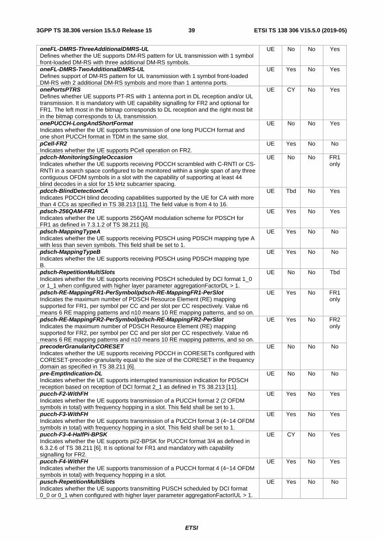
ETSI
ETSI TS 138 306 V15.5.0 (2019-05)393GPP TS 38.306 version 15.5.0 Release 15
oneFL-DMRS-ThreeAdditionalDMRS-UL Defines whether the UE supports DM-RS pattern for UL transmission with 1 symbol front-loaded DM-RS with three additional DM-RS symbols.
UE No No Yes
oneFL-DMRS-TwoAdditionalDMRS-UL Defines support of DM-RS pattern for UL transmission with 1 symbol front-loaded DM-RS with 2 additional DM-RS symbols and more than 1 antenna ports.
UE Yes No Yes
onePortsPTRS Defines whether UE supports PT-RS with 1 antenna port in DL reception and/or UL transmission. It is mandatory with UE capability signalling for FR2 and optional for FR1. The left most in the bitmap corresponds to DL reception and the right most bit in the bitmap corresponds to UL transmission.
UE CY No Yes
onePUCCH-LongAndShortFormat Indicates whether the UE supports transmission of one long PUCCH format and one short PUCCH format in TDM in the same slot.
UE No No Yes
pCell-FR2 Indicates whether the UE supports PCell operation on FR2.
UE Yes No No
pdcch-MonitoringSingleOccasion Indicates whether the UE supports receiving PDCCH scrambled with C-RNTI or CS-RNTI in a search space configured to be monitored within a single span of any three contiguous OFDM symbols in a slot with the capability of supporting at least 44 blind decodes in a slot for 15 kHz subcarrier spacing.
UE No No FR1 only
pdcch-BlindDetectionCA Indicates PDCCH blind decoding capabilities supported by the UE for CA with more than 4 CCs as specified in TS 38.213 [11]. The field value is from 4 to 16.
UE Tbd No Yes
pdsch-256QAM-FR1 Indicates whether the UE supports 256QAM modulation scheme for PDSCH for FR1 as defined in 7.3.1.2 of TS 38.211 [6].
UE Yes No Yes
pdsch-MappingTypeA Indicates whether the UE supports receiving PDSCH using PDSCH mapping type A with less than seven symbols. This field shall be set to 1.
UE Yes No No
pdsch-MappingTypeB Indicates whether the UE supports receiving PDSCH using PDSCH mapping type B.
UE Yes No No
pdsch-RepetitionMultiSlots Indicates whether the UE supports receiving PDSCH scheduled by DCI format 1_0 or 1_1 when configured with higher layer parameter aggregationFactorDL > 1.
UE No No Tbd
pdsch-RE-MappingFR1-PerSymbol/pdsch-RE-MappingFR1-PerSlot Indicates the maximum number of PDSCH Resource Element (RE) mapping supported for FR1, per symbol per CC and per slot per CC respectively. Value n6 means 6 RE mapping patterns and n10 means 10 RE mapping patterns, and so on.
UE Yes No FR1 only
pdsch-RE-MappingFR2-PerSymbol/pdsch-RE-MappingFR2-PerSlot Indicates the maximum number of PDSCH Resource Element (RE) mapping supported for FR2, per symbol per CC and per slot per CC respectively. Value n6 means 6 RE mapping patterns and n10 means 10 RE mapping patterns, and so on.
UE Yes No FR2 only
precoderGranularityCORESET Indicates whether the UE supports receiving PDCCH in CORESETs configured with CORESET-precoder-granularity equal to the size of the CORESET in the frequency domain as specified in TS 38.211 [6].
UE No No No
pre-EmptIndication-DL Indicates whether the UE supports interrupted transmission indication for PDSCH reception based on reception of DCI format 2_1 as defined in TS 38.213 [11].
UE No No No
pucch-F2-WithFH Indicates whether the UE supports transmission of a PUCCH format 2 (2 OFDM symbols in total) with frequency hopping in a slot. This field shall be set to 1.
UE Yes No Yes
pucch-F3-WithFH Indicates whether the UE supports transmission of a PUCCH format 3 (4~14 OFDM symbols in total) with frequency hopping in a slot. This field shall be set to 1.
UE Yes No Yes
pucch-F3-4-HalfPi-BPSK Indicates whether the UE supports pi/2-BPSK for PUCCH format 3/4 as defined in 6.3.2.6 of TS 38.211 [6]. It is optional for FR1 and mandatory with capability signalling for FR2.
UE CY No Yes
pucch-F4-WithFH Indicates whether the UE supports transmission of a PUCCH format 4 (4~14 OFDM symbols in total) with frequency hopping in a slot.
UE Yes No Yes
pusch-RepetitionMultiSlots Indicates whether the UE supports transmitting PUSCH scheduled by DCI format 0_0 or 0_1 when configured with higher layer parameter aggregationFactorIUL > 1.
UE Yes No No

ETSI
ETSI TS 138 306 V15.5.0 (2019-05)403GPP TS 38.306 version 15.5.0 Release 15
pucch-Repetition-F1-3-4 Indicates whether the UE supports transmission of a PUCCH format 1 or 3 or 4 over multiple slots with the repetition factor 2, 4 or 8.
UE Yes No No
pusch-HalfPi-BPSK Indicates whether the UE supports pi/2-BPSK modulation scheme for PUSCH as defined in 6.3.1.2 of TS 38.211 [6]. It is optional for FR1 and mandatory with capability signalling for FR2.
UE CY No Yes
pusch-LBRM Indicates whether the UE supports limited buffer rate matching in UL as specified in TS 38.212 [10].
UE No No Yes
ra-Type0-PUSCH Indicates whether the UE supports resource allocation Type 0 for PUSCH as specified in TS 38.214 [12].
UE No No No
rateMatchingCtrlResrcSetDynamic Indicates whether the UE supports dynamic rate matching for DL control resource set.
UE Yes No No
rateMatchingResrcSetDynamic Indicates whether the UE supports receiving PDSCH with resource mapping that excludes the REs corresponding to resource sets configured with RB-symbol level granularity based on dynamic indication in the scheduling DCI as specified in TS 38.214 [12].
UE No No No
rateMatchingResrcSetSemi-Static Indicates whether the UE supports receiving PDSCH with resource mapping that excludes the REs corresponding to resource sets configured with RB-symbol level granularity following the semi-static configuration as specified in TS 38.214 [12].
UE Yes No No
scs-60kHz Indicates whether the UE supports 60kHz subcarrier spacing for data channel in FR1 as defined in clause 4.2-1 of TS 38.211 [6].
UE No No FR1 only
semiOpenLoopCSI Indicates whether UE supports CSI reporting with report quantity set to 'CRI/RI/i1' as defined in clause 5.2.1.4 of TS 38.214 [12].
UE No No Yes
semiStaticHARQ-ACK-Codebook Indicates whether the UE supports HARQ-ACK codebook constructed by semi-static configuration.
UE Yes No No
spatialBundlingHARQ-ACK Indicates whether the UE supports spatial bundling of HARQ-ACK bits carried on PUCCH or PUSCH per PUCCH group. With spatial bundling, two HARQ-ACK bits for a DL MIMO data is bundled into a single bit by logical "AND" operation.
UE Yes No No
sp-CSI-IM Indicates whether the UE supports semi-persistent CSI-IM.
UE No No Yes
sp-CSI-ReportPUCCH Indicates whether UE supports semi-persistent CSI reporting using PUCCH formats 2, 3 and 4.
UE No No No
sp-CSI-ReportPUSCH Indicates whether UE supports semi-persistent CSI reporting using PUSCH.
UE No No No
sp-CSI-RS Indicates whether the UE supports semi-persistent CSI-RS.
UE Yes No Yes
supportedDMRS-TypeDL Defines supported DM-RS configuration types at the UE for DL reception. Type 1 is mandatory with capability signaling. Type 2 is optional.
UE CY No Yes
supportedDMRS-TypeUL Defines supported DM-RS configuration types at the UE for UL transmission. Support both type 1 and type 2 are mandatory with capability signalling.
UE Yes No Yes
tdd-MultiDL-UL-SwitchPerSlot Indicates whether the UE supports more than one switch points in a slot for actual DL/UL transmission(s).
UE No TDD only
Yes
tpc-PUCCH-RNTI Indicates whether the UE supports group DCI message based on TPC-PUCCH-RNTI for TPC commands for PUCCH.
UE No No Yes
tpc-PUSCH-RNTI Indicates whether the UE supports group DCI message based on TPC-PUSCH-RNTI for TPC commands for PUSCH.
UE No No Yes
tpc-SRS-RNTI Indicates whether the UE supports group DCI message based on TPC-SRS-RNTI for TPC commands for SRS.
UE No No Yes

ETSI
ETSI TS 138 306 V15.5.0 (2019-05)413GPP TS 38.306 version 15.5.0 Release 15
twoDifferentTPC-Loop-PUCCH Indicates whether the UE supports two different TPC loops for PUCCH closed loop power control.
UE Yes Yes Yes
twoDifferentTPC-Loop-PUSCH Indicates whether the UE supports two different TPC loops for PUSCH closed loop power control.
UE Yes Yes Yes
twoFL-DMRS Defines whether the UE supports DM-RS pattern for DL reception and/or UL transmission with 2 symbols front-loaded DM-RS without additional DM-RS symbols. The left most in the bitmap corresponds to DL reception and the right most bit in the bitmap corresponds to UL transmission.
UE Yes No Yes
twoFL-DMRS-TwoAdditionalDMRS-UL Defines whether the UE supports DM-RS pattern for UL transmission with 2 symbols front-loaded DM-RS with one additional 2 symbols DM-RS.
UE Yes No Yes
twoPUCCH-AnyOthersInSlot Indicates whether the UE supports transmission of two PUCCH formats in TDM in the same slot, which are not covered by twoPUCCH-F0-2-ConsecSymbols and onePUCCH-LongAndShortFormat.
UE No No Yes
twoPUCCH-F0-2-ConsecSymbols Indicates whether the UE supports transmission of two PUCCHs of format 0 or 2 in consecutive symbols in a slot.
UE No Yes Yes
type1-PUSCH-RepetitionMultiSlots Indicates whether the UE supports Type 1 PUSCH transmissions with configured grant as specified in TS 38.214 [12] with UL-TWG-repK value equal to 2, 4, or 8 with a single repetition of the transport block within each slot, and redundancy version pattern as indicated by UL-TWG-RV-rep. A UE supporting this feature shall also support Type 1 PUSCH transmissions with configured grant as specified in TS 38.214 [12] with UL-TWG-repK value of one.
UE No No No
type2-PUSCH-RepetitionMultiSlots Indicates whether the UE supports Type 1 PUSCH transmissions with configured grant as specified in TS 38.214 [12] with UL-TWG-repK value equal to 2, 4, or 8 with a single repetition of the transport block within each slot, and redundancy version pattern as indicated by UL-TWG-RV-rep. A UE supporting this feature shall also support Type 2 PUSCH transmissions with configured grant as specified in TS 38.214 [12] with UL-TWG-repK value of one.
UE No No No
type2-SP-CSI-Feedback-LongPUCCH Indicates whether UE supports Type II CSI semi-persistent CSI reporting over PUCCH Formats 3 and 4 as defined in clause 5.2.4 of TS 38.214 [12].
UE No No No
uci-CodeBlockSegmentation Indicates whether the UE supports segmenting UCI into multiple code blocks depending on the payload size.
UE Yes No Yes
ul-64QAM-MCS-TableAlt Indicates whether the UE supports the alternative 64QAM MCS table for PUSCH with and without transform precoding respectively.
UE No No Yes
ul-SchedulingOffset Indicates whether the UE supports UL scheduling slot offset (K2) greater than 12.
UE Yes Yes Yes

ETSI
ETSI TS 138 306 V15.5.0 (2019-05)423GPP TS 38.306 version 15.5.0 Release 15
4.2.7.11 Other PHY parameters
Definitions for parameters Per M FDD-TDD DIFF
FR1-FR2 DIFF
appliedFreqBandListFilter Mirrors the FreqBandList that the NW provided in the capability enquiry, if any. The UE filtered the band combinations in the supportedBandCombinationList in accordance with this appliedFreqBandListFilter.
UE No No No
downlinkSetEUTRA Indicates the features that the UE supports on the DL carriers corresponding to one EUTRA band entry in a band combination by FeatureSetEUTRA-DownlinkId. The FeatureSetEUTRA-DownlinkId = 0 means that the UE does not support a EUTRA DL carrier in this band of a band combination.
Band Tbd No No
downlinkSetNR Indicates the features that the UE supports on the DL carriers corresponding to one NR band entry in a band combination by FeatureSetDownlinkId. The FeatureSetDownlinkId = 0 means that the UE does not support a DL carrier in this band of a band combination. A fallback per band feature set resulting from the reported DL feature set that has fallback per CC feature set is not signalled but the UE shall support it.
Band Tbd No No
featureSetCombinations Pools of feature sets that the UE supports on the NR CA or MR-DC band combinations.
UE Tbd No No
featureSets Pools of downlink and uplink features sets as well as a pool of FeatureSetCombination elements. A FeatureSetCombination refers to the IDs of the feature set(s) that the UE supports in that FeatureSetCombination. The BandCombination entries in the BandCombinationList then indicate the ID of the FeatureSetCombination that the UE supports fot that band combination.
UE Tbd No No
naics-Capability-List Indicates that UE in MR-DC supports NAICS as defined in defined in TS 36.331 [17].
UE No No No
supportedBandCombinationList Defines the supported CA and/or MR-DC band combinations by the UE. For each band combination the UE identifies the associated feature set combination by featureSetCombinations index referring to featureSetCombination. A fallback band combination resulting from the reported CA and MR-DC band combination is not signalled but the UE shall support it. For intra-band non-contiguous CA band combinations, the UE only includes one band combination, and exclude the others for which the presence of uplink CA bandwidth class in the band combination entry is different. One band combination entry can also indicate support of any other possible permutations in the presence of uplink CA bandwidth class where a paired downlink CA bandwidth class is the same or where the number of UL CCs is smaller than the one of paired DL CCs expressed by the CA bandwidth class, as specified in TS 36.306 [15]. For these band combinations not included in the capability, the supported feature set is the same as the ones for the band combination included in the UE capability.
UE Yes No No
supportedBandListNR Includes the supported NR bands as defined in TS 38.101-1 [2] and TS 38.101-2 [3].
UE Yes No No
uplinkSetEUTRA Indicates the features that the UE supports on the UL carriers corresponding to one EUTRA band entry in a band combination by FeatureSetEUTRA-UplinkId. The FeatureSetUplinkId = 0 means that the UE does not support a UL carrier in this band of a band combination.
Band Tbd No No
uplinkSetNR Indicates the features that the UE supports on the UL carriers corresponding to one NR band entry in a band combination by FeatureSetUplinkId. The FeatureSetUplinkId = 0 means that the UE does not support a UL carrier in this band of a band combination. A fallback per band feature set resulting from the reported UL feature set that has fallback per CC feature set is not signalled but the UE shall support it.
Band Tbd No No
ETSI
ETSI TS 138 306 V15.5.0 (2019-05)433GPP TS 38.306 version 15.5.0 Release 15
4.2.8 Void
ETSI
ETSI TS 138 306 V15.5.0 (2019-05)443GPP TS 38.306 version 15.5.0 Release 15
4.2.9 MeasAndMobParameters
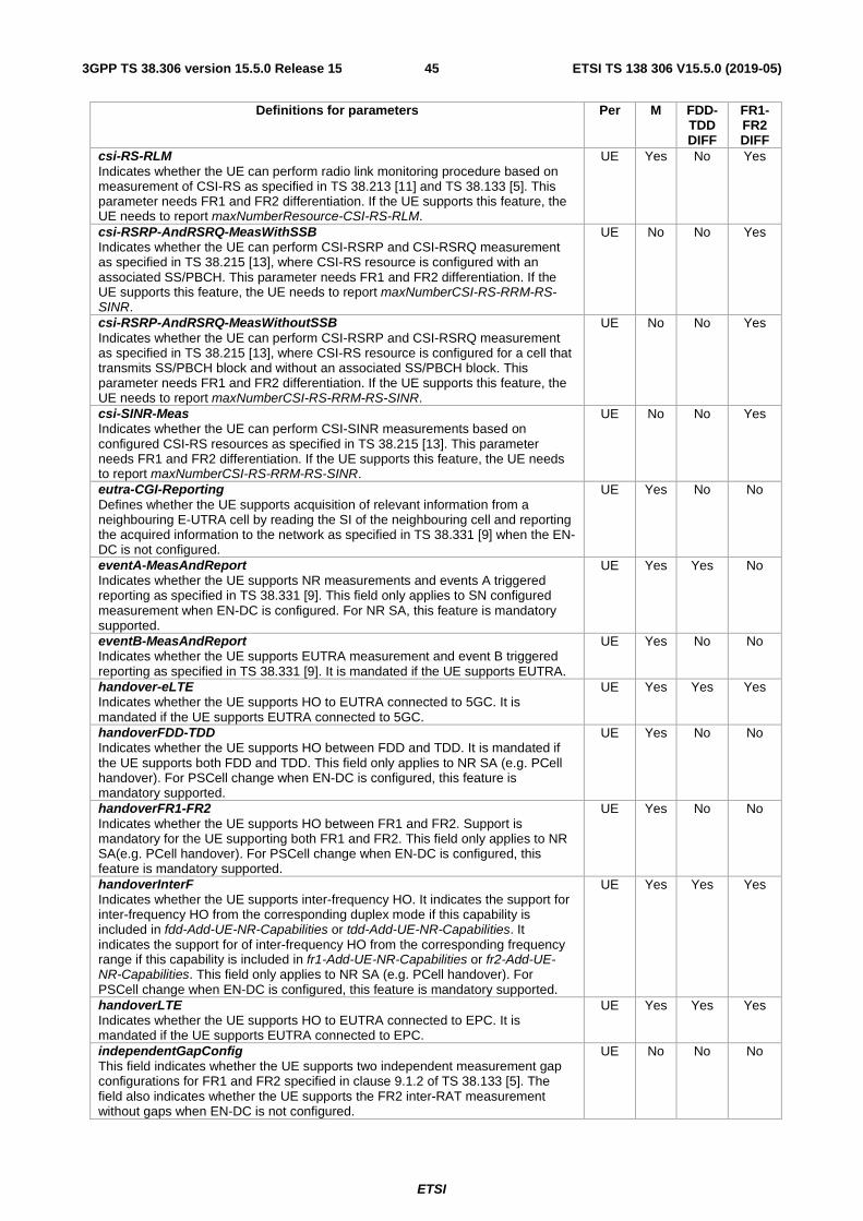
ETSI
ETSI TS 138 306 V15.5.0 (2019-05)453GPP TS 38.306 version 15.5.0 Release 15
Definitions for parameters Per M FDD-TDD DIFF
FR1-FR2 DIFF
csi-RS-RLM Indicates whether the UE can perform radio link monitoring procedure based on measurement of CSI-RS as specified in TS 38.213 [11] and TS 38.133 [5]. This parameter needs FR1 and FR2 differentiation. If the UE supports this feature, the UE needs to report maxNumberResource-CSI-RS-RLM.
UE Yes No Yes
csi-RSRP-AndRSRQ-MeasWithSSB Indicates whether the UE can perform CSI-RSRP and CSI-RSRQ measurement as specified in TS 38.215 [13], where CSI-RS resource is configured with an associated SS/PBCH. This parameter needs FR1 and FR2 differentiation. If the UE supports this feature, the UE needs to report maxNumberCSI-RS-RRM-RS-SINR.
UE No No Yes
csi-RSRP-AndRSRQ-MeasWithoutSSB Indicates whether the UE can perform CSI-RSRP and CSI-RSRQ measurement as specified in TS 38.215 [13], where CSI-RS resource is configured for a cell that transmits SS/PBCH block and without an associated SS/PBCH block. This parameter needs FR1 and FR2 differentiation. If the UE supports this feature, the UE needs to report maxNumberCSI-RS-RRM-RS-SINR.
UE No No Yes
csi-SINR-Meas Indicates whether the UE can perform CSI-SINR measurements based on configured CSI-RS resources as specified in TS 38.215 [13]. This parameter needs FR1 and FR2 differentiation. If the UE supports this feature, the UE needs to report maxNumberCSI-RS-RRM-RS-SINR.
UE No No Yes
eutra-CGI-Reporting Defines whether the UE supports acquisition of relevant information from a neighbouring E-UTRA cell by reading the SI of the neighbouring cell and reporting the acquired information to the network as specified in TS 38.331 [9] when the EN-DC is not configured.
UE Yes No No
eventA-MeasAndReport Indicates whether the UE supports NR measurements and events A triggered reporting as specified in TS 38.331 [9]. This field only applies to SN configured measurement when EN-DC is configured. For NR SA, this feature is mandatory supported.
UE Yes Yes No
eventB-MeasAndReport Indicates whether the UE supports EUTRA measurement and event B triggered reporting as specified in TS 38.331 [9]. It is mandated if the UE supports EUTRA.
UE Yes No No
handover-eLTE Indicates whether the UE supports HO to EUTRA connected to 5GC. It is mandated if the UE supports EUTRA connected to 5GC.
UE Yes Yes Yes
handoverFDD-TDD Indicates whether the UE supports HO between FDD and TDD. It is mandated if the UE supports both FDD and TDD. This field only applies to NR SA (e.g. PCell handover). For PSCell change when EN-DC is configured, this feature is mandatory supported.
UE Yes No No
handoverFR1-FR2 Indicates whether the UE supports HO between FR1 and FR2. Support is mandatory for the UE supporting both FR1 and FR2. This field only applies to NR SA(e.g. PCell handover). For PSCell change when EN-DC is configured, this feature is mandatory supported.
UE Yes No No
handoverInterF Indicates whether the UE supports inter-frequency HO. It indicates the support for inter-frequency HO from the corresponding duplex mode if this capability is included in fdd-Add-UE-NR-Capabilities or tdd-Add-UE-NR-Capabilities. It indicates the support for of inter-frequency HO from the corresponding frequency range if this capability is included in fr1-Add-UE-NR-Capabilities or fr2-Add-UE-NR-Capabilities. This field only applies to NR SA (e.g. PCell handover). For PSCell change when EN-DC is configured, this feature is mandatory supported.
UE Yes Yes Yes
handoverLTE Indicates whether the UE supports HO to EUTRA connected to EPC. It is mandated if the UE supports EUTRA connected to EPC.
UE Yes Yes Yes
independentGapConfig This field indicates whether the UE supports two independent measurement gap configurations for FR1 and FR2 specified in clause 9.1.2 of TS 38.133 [5]. The field also indicates whether the UE supports the FR2 inter-RAT measurement without gaps when EN-DC is not configured.
UE No No No
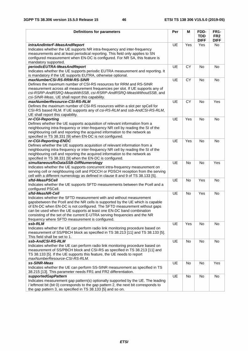
ETSI
ETSI TS 138 306 V15.5.0 (2019-05)463GPP TS 38.306 version 15.5.0 Release 15
Definitions for parameters Per M FDD-TDD DIFF
FR1-FR2 DIFF
intraAndInterF-MeasAndReport Indicates whether the UE supports NR intra-frequency and inter-frequency measurements and at least periodical reporting. This field only applies to SN configured measurement when EN-DC is configured. For NR SA, this feature is mandatory supported.
UE Yes Yes No
periodicEUTRA-MeasAndReport Indicates whether the UE supports periodic EUTRA measurement and reporting. It is mandatory if the UE supports EUTRA, otherwise optional.
UE CY No No
maxNumberCSI-RS-RRM-RS-SINR Defines the maximum number of CSI-RS resources for RRM and RS-SINR measurement across all measurement frequencies per slot. If UE supports any of csi-RSRP-AndRSRQ-MeasWithSSB, csi-RSRP-AndRSRQ-MeasWithoutSSB, and csi-SINR-Meas, UE shall report this capability.
UE CY No No
maxNumberResource-CSI-RS-RLM Defines the maximum number of CSI-RS resources within a slot per spCell for CSI-RS based RLM. If UE supports any of csi-RS-RLM and ssb-AndCSI-RS-RLM, UE shall report this capability.
UE CY No Yes
nr-CGI-Reporting Defines whether the UE supports acquisition of relevant information from a neighbouring intra-frequency or inter-frequency NR cell by reading the SI of the neighbouring cell and reporting the acquired information to the network as specified in TS 38.331 [9] when EN-DC is not configured.
UE Yes No No
nr-CGI-Reporting-ENDC Defines whether the UE supports acquisition of relevant information from a neighbouring intra-frequency or inter-frequency NR cell by reading the SI of the neighbouring cell and reporting the acquired information to the network as specified in TS 38.331 [9] when the EN-DC is configured.
UE Yes No No
simultaneousRxDataSSB-DiffNumerology Indicates whether the UE supports concurrent intra-frequency measurement on serving cell or neighbouring cell and PDCCH or PDSCH reception from the serving cell with a different numerology as defined in clause 8 and 9 of TS 38.133 [5].
UE No No Yes
sftd-MeasPSCell Indicates whether the UE supports SFTD measurements between the Pcell and a configured PSCell.
UE No Yes No
sftd-MeasNR-Cell Indicates whether the SFTD measurement with and without measurement gapsbetween the Pcell and the NR cells is supported by the UE which is capable of EN-DC when EN-DC is not configured. The SFTD measurement without gaps can be used when the UE supports at least one EN-DC band combination consisting of the set of the current E-UTRA serving frequencies and the NR frequency where SFTD measurement is configured.
UE No Yes No
ssb-RLM Indicates whether the UE can perform radio link monitoring procedure based on measurement of SS/PBCH block as specified in TS 38.213 [11] and TS 38.133 [5]. This field shall be set to 1.
UE Yes No No
ssb-AndCSI-RS-RLM Indicates whether the UE can perform radio link monitoring procedure based on measurement of SS/PBCH block and CSI-RS as specified in TS 38.213 [11] and TS 38.133 [5]. If the UE supports this feature, the UE needs to report maxNumberResource-CSI-RS-RLM.
UE No No No
ss-SINR-Meas Indicates whether the UE can perform SS-SINR measurement as specified in TS 38.215 [13]. This parameter needs FR1 and FR2 differentiation.
UE No No Yes
supportedGapPattern Indicates measurement gap pattern(s) optionally supported by the UE. The leading / leftmost bit (bit 0) corresponds to the gap pattern 2, the next bit corresponds to the gap pattern 3, as specified in TS 38.133 [5] and so on.
UE No No No

ETSI
ETSI TS 138 306 V15.5.0 (2019-05)473GPP TS 38.306 version 15.5.0 Release 15
4.2.10 Inter-RAT parameters
Definitions for parameters Per M FDD-TDD DIFF
mfbi-EUTRA Indicates whether the UE supports the mechanisms defined for cells broadcasting multi band information i.e. comprehending multiBandInfoList defined in TS 36.331 [17].
UE Yes No
modifiedMRP-BehaviorEUTRA modifiedMPR-Behavior in 4.3.5.10, TS 36.306 [15].
UE No No
multiNS-Pmax-EUTRA multiNS-Pmax defined in 4.3.5.16, TS 36.306 [15].
UE No No
rs-SINR-MeasEUTRA rs-SINR-Meas in 4.3.6.13, TS 36.306 [15].
UE No No
rsrqMeasWidebandEUTRA rsrqMeasWideband in 4.3.6.2, TS 36.306 [15]
UE No Yes
4.2.10.1 Void
4.2.10.2 Void
4.2.11 Void
4.2.12 Void
4.2.13 IMS Parameters
Definitions for parameters Per M FDD-TDD DIFF
FR1-FR2 DIFF
voiceOverEUTRA-5GC Indicates whether the UE supports IMS voice over E-UTRA via 5GC.
UE No No No
voiceOverNR Indicates whether the UE supports IMS voice over NR. It is mandated to the IMS voice capable UE in NR otherwise optional.
UE No No Yes
4.2.14 RRC buffer size
The RRC buffer size is defined as the maximum overall RRC configuration size that the UE is required to store. The RRC buffer size is 45Kbytes.
5 Optional features without UE radio access capability parameters
6 Conditionally mandatory features without UE radio access capability parameters
Features Condition Skipping UL configured grant if no data to transmit. Either configuredUL-GrantType1 or configuredUL-GrantType2
is supported. Downlink SDAP header Either NAS reflective QoS or as-ReflectiveQoS is supported.
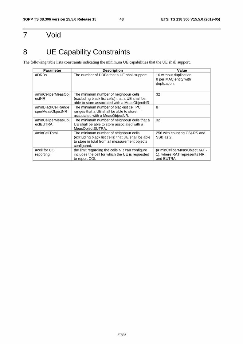
ETSI
ETSI TS 138 306 V15.5.0 (2019-05)483GPP TS 38.306 version 15.5.0 Release 15
7 Void
8 UE Capability Constraints The following table lists constraints indicating the minimum UE capabilities that the UE shall support.
Parameter Description Value #DRBs The number of DRBs that a UE shall support. 16 without duplication
8 per MAC entity with duplication.
#minCellperMeasObjectNR
The minimum number of neighbour cells (excluding black list cells) that a UE shall be able to store associated with a MeasObjectNR.
32
#minBlackCellRangesperMeasObjectNR
The minimum number of blacklist cell PCI ranges that a UE shall be able to store associated with a MeasObjectNR.
8
#minCellperMeasObjectEUTRA
The minimum number of neighbour cells that a UE shall be able to store associated with a MeasObjectEUTRA.
32
#minCellTotal The minimum number of neighbour cells (excluding black list cells) that UE shall be able to store in total from all measurement objects configured.
256 with counting CSI-RS and SSB as 2.
#cell for CGI reporting
the limit regarding the cells NR can configure includes the cell for which the UE is requested to report CGI.
(# minCellperMeasObjectRAT - 1), where RAT represents NR and EUTRA.

ETSI
ETSI TS 138 306 V15.5.0 (2019-05)493GPP TS 38.306 version 15.5.0 Release 15
Annex A (informative): Change history
Change history Date Meetin
g TDoc CR Rev Cat Subject/Comment New
version 06/2017 RAN2#
98 R2-1704810 First version 0.0.1
06/2017 RAN2#NR2
R2-1707386 0.0.2
08/2017 RAN2#99
R2-1708750 0.0.3
12/2017 RAN2#100
R2-1712587 0.0.4
12/2017 RAN2#100
R2-1714141 0.0.5
12/2017 RAN2#100
R2-1714271 0.1.0
12/2017 RP-78 RP-172521 Submitted to RAN#78 for approval 1.0.0 12/2017 RP-78 Upgraded to Rel-15 15.0.0 03/2018 RP-79 RP-180440 0003 3 F Updates on UE capabilities 15.1.0 06/2018 RP-80 RP-181216 0009 2 B Introduce ANR in NR 15.2.0 RP-80 RP-181216 0012 1 F Miscellaneous corrections 15.2.0 RP-80 RP-181216 0013 - B Delay budget report and MAC CE adaptation for NR for TS 38.306 15.2.0 09/2018 RP-81 RP-181940 0008 4 F Correction on total layer2 buffer size 15.3.0 RP-81 RP-181942 0024 1 F Introduction of UE capability constraints 15.3.0 RP-81 RP-181942 0030 - F 38.306 corrections and cleanup 15.3.0 12/2018 RP-82 RP-182651 0016 4 F Clarification for Interruption-based and gap-based SFTD measurement 15.4.0 RP-82 RP-182653 0033 1 F Timer based BWP switching 15.4.0 RP-82 RP-182652 0035 2 F Additional UE capabilities for NR standalone 15.4.0 RP-82 RP-182651 0037 1 F Clarification to UE capability of independentGapConfig for inter-RAT
NR measurement not yet configured with EN-DC 15.4.0
RP-82 RP-182661 0038 2 F Update of L2 capability parameters 15.4.0 RP-82 RP-182660 0047 2 F Clarification on physical layer parameters of UE capability 15.4.0 RP-82 RP-182666 0050 3 F Introduce RRC buffer size in NR 15.4.0 RP-82 RP-182664 0051 2 F Clarification of multipleConfiguredGrants 15.4.0 RP-82 RP-182664 0052 2 F CR to 38.306 for PDCP CA duplication for SRB 15.4.0 RP-82 RP-182661 0054 1 F UE capability handling for FDD/TDD and FR1/FR2 15.4.0 RP-82 RP-182663 0057 1 F Clarify for per CC UL/DL modulation order capabilities 15.4.0 RP-82 RP-182664 0058 1 F Inter-frequency handover capability 15.4.0 RP-82 RP-182665 0060 3 F UE capability on PA architecture 15.4.0 RP-82 RP-182661 0062 1 F CR on signaling contiguous and non-contiguous EN-DC capability 15.4.0 RP-82 RP-182813 0063 6 F Update of UE capabilities 15.4.0 RP-82 RP-182662 0065 2 F Introduction of SRS switching capability 15.4.0 RP-82 RP-182667 0068 2 B CR on introduction of UE overheating support in NR SA scenario 15.4.0 RP-82 RP-182664 0071 - F Introduction of SRS switching capability 15.4.0 03/2019 RP-83 RP-190634 0073 1 F Capability for aperiodic CSI-RS triggering with different numerology
between PDCCH and CSI-RS 15.5.0
RP-83 RP-190542 0074 1 F Layer-1 capability update 15.5.0 RP-83 RP-190545 0075 2 F CR to 38.306 on introducing nr-CGI-Reporting-ENDC 15.5.0 RP-83 RP-190545 0086 2 F CR to clarify intra-NR handover capabilities 15.5.0 RP-83 RP-190546 0088 3 F Clarification for PDSCHs and PUSCHs per slot for different TBs for UE
capable of processing time capability 1 15.5.0
RP-83 RP-190542 0092 2 F Correction to mandatory supported capability signaling 15.5.0 RP-83 RP-190542 0097 2 F Miscellaneous corrections 15.5.0 RP-83 RP-190545 0098 2 F Correction on supportedBandwidthCombinationSetEUTRA-v1530
usage 15.5.0
RP-83 RP-190543 0099 - F Clarification on signaling the bandwidth class 15.5.0 RP-83 RP-190545 0100 1 F Clarification on Frequency Separation Class 15.5.0 RP-83 RP-190544 0101 - F CR on Processing delay requirements for RRC Resume procedures in
TS 38.306 15.5.0
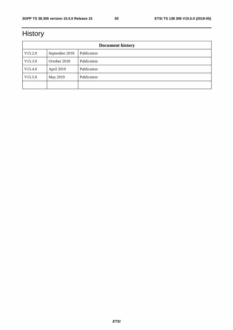
ETSI
ETSI TS 138 306 V15.5.0 (2019-05)503GPP TS 38.306 version 15.5.0 Release 15
History
Document history
V15.2.0 September 2018 Publication
V15.3.0 October 2018 Publication
V15.4.0 April 2019 Publication
V15.5.0 May 2019 Publication


![TS 125 306 - V10.2.0 - Universal Mobile …13] 3GPP TS 25.308 "High Speed Downlink Packet Access (HSDPA); Overall description; Stage 2".](https://static.fdocuments.in/doc/165x107/5b4c5cf77f8b9a9a408b9c8e/ts-125-306-v1020-universal-mobile-13-3gpp-ts-25308-high-speed-downlink.jpg)