![Draft ETSI EN 301 489-50 V2.2...2002/02/02 · 4G IMT-advanced ETSI TS 137 104 [21] ETSI TS 137 141 [12] ETSI TS 137 114 [31] ETSI TS 137 145-1 [13] ETSI TS 137 145-2 [14] WMAN (OFDMA)](https://static.fdocuments.in/doc/165x107/60e0dd64bbf8f11159724729/draft-etsi-en-301-489-50-v22-20020202-4g-imt-advanced-etsi-ts-137-104.jpg)
TS 134 123-3 - V5.5.0 - Universal Mobile ...€¦ · 3GPP TS 34.123-3 version 5.5.0 Release 5 ETSI...
374
ETSI TS 134 123-3 V5.5.0 (2006-06) Technical Specification Universal Mobile Telecommunications System (UMTS); User Equipment (UE) conformance specification; Part 3: Abstract test suites (ATSs) (3GPP TS 34.123-3 version 5.5.0 Release 5)
Transcript of TS 134 123-3 - V5.5.0 - Universal Mobile ...€¦ · 3GPP TS 34.123-3 version 5.5.0 Release 5 ETSI...
ETSI TS 134 123-3 V5.5.0 (2006-06)
Technical Specification
Universal Mobile Telecommunications System (UMTS);User Equipment (UE) conformance specification;
Part 3: Abstract test suites (ATSs)(3GPP TS 34.123-3 version 5.5.0 Release 5)
�

ETSI
ETSI TS 134 123-3 V5.5.0 (2006-06) 1 3GPP TS 34.123-3 version 5.5.0 Release 5
Reference RTS/TSGR-0534123-3v550
Keywords UMTS
ETSI
650 Route des Lucioles F-06921 Sophia Antipolis Cedex - FRANCE
Tel.: +33 4 92 94 42 00 Fax: +33 4 93 65 47 16
Siret N° 348 623 562 00017 - NAF 742 C
Association à but non lucratif enregistrée à la Sous-Préfecture de Grasse (06) N° 7803/88
Important notice
Individual copies of the present document can be downloaded from: http://www.etsi.org
The present document may be made available in more than one electronic version or in print. In any case of existing or perceived difference in contents between such versions, the reference version is the Portable Document Format (PDF).
In case of dispute, the reference shall be the printing on ETSI printers of the PDF version kept on a specific network drive within ETSI Secretariat.
Users of the present document should be aware that the document may be subject to revision or change of status. Information on the current status of this and other ETSI documents is available at
http://portal.etsi.org/tb/status/status.asp
If you find errors in the present document, please send your comment to one of the following services: http://portal.etsi.org/chaircor/ETSI_support.asp
Copyright Notification
No part may be reproduced except as authorized by written permission. The copyright and the foregoing restriction extend to reproduction in all media.
© European Telecommunications Standards Institute 2006.
All rights reserved.
DECTTM, PLUGTESTSTM and UMTSTM are Trade Marks of ETSI registered for the benefit of its Members. TIPHONTM and the TIPHON logo are Trade Marks currently being registered by ETSI for the benefit of its Members. 3GPPTM is a Trade Mark of ETSI registered for the benefit of its Members and of the 3GPP Organizational Partners.
ETSI
ETSI TS 134 123-3 V5.5.0 (2006-06) 2 3GPP TS 34.123-3 version 5.5.0 Release 5
Intellectual Property Rights IPRs essential or potentially essential to the present document may have been declared to ETSI. The information pertaining to these essential IPRs, if any, is publicly available for ETSI members and non-members, and can be found in ETSI SR 000 314: "Intellectual Property Rights (IPRs); Essential, or potentially Essential, IPRs notified to ETSI in respect of ETSI standards", which is available from the ETSI Secretariat. Latest updates are available on the ETSI Web server (http://webapp.etsi.org/IPR/home.asp).
Pursuant to the ETSI IPR Policy, no investigation, including IPR searches, has been carried out by ETSI. No guarantee can be given as to the existence of other IPRs not referenced in ETSI SR 000 314 (or the updates on the ETSI Web server) which are, or may be, or may become, essential to the present document.
Foreword This Technical Specification (TS) has been produced by ETSI 3rd Generation Partnership Project (3GPP).
The present document may refer to technical specifications or reports using their 3GPP identities, UMTS identities or GSM identities. These should be interpreted as being references to the corresponding ETSI deliverables.
The cross reference between GSM, UMTS, 3GPP and ETSI identities can be found under http://webapp.etsi.org/key/queryform.asp .
ETSI
ETSI TS 134 123-3 V5.5.0 (2006-06) 3 3GPP TS 34.123-3 version 5.5.0 Release 5
Contents
Intellectual Property Rights ................................................................................................................................2
Foreword.............................................................................................................................................................2
Foreword...........................................................................................................................................................11
Introduction ......................................................................................................................................................11
1 Scope ......................................................................................................................................................12
2 References ..............................................................................................................................................12
3 Definitions and abbreviations.................................................................................................................15 3.1 Definitions........................................................................................................................................................15 3.2 Abbreviations ...................................................................................................................................................15
4 Requirements on the TTCN development..............................................................................................15
5 ATS structure .........................................................................................................................................16 5.1 Modularity........................................................................................................................................................16 5.1.1 Module structure .........................................................................................................................................16 5.1.2 Contents of the modules .............................................................................................................................18 5.1.3 Example of a working platform ..................................................................................................................18
6 Test method and testing architecture......................................................................................................19 6.1 Test method ......................................................................................................................................................19 6.2 Testing architecture ..........................................................................................................................................20 6.2.1 Lower Tester (LT) ......................................................................................................................................20 6.2.2 Configuration and initialization ..................................................................................................................20 6.2.3 Upper Tester (UT) ......................................................................................................................................21 6.2.4 TTCN..........................................................................................................................................................21 6.2.5 Model extension..........................................................................................................................................21 6.2.6 Multiplexing of RLC services.....................................................................................................................21 6.3 NAS test method and architecture ....................................................................................................................21 6.3.1 Test configuration .......................................................................................................................................21 6.3.2 Routing UL NAS massages in SS...............................................................................................................22 6.4 RRC and RAB test method and architecture ....................................................................................................23 6.4.1 Test configuration .......................................................................................................................................23 6.4.2 RAB test method.........................................................................................................................................24 6.4.2.1 Sending data on the same TTI...............................................................................................................24 6.4.2.2 Sending continuous data on consecutive TTIs ......................................................................................24 6.5 RLC test method and architecture ....................................................................................................................25 6.5.1 Testing architecture.....................................................................................................................................25 6.5.2 Test method ................................................................................................................................................26 6.5.2.1 Handling SUFIs in TTCN .....................................................................................................................29 6.5.2.2 Guideline for RLC test execution..........................................................................................................30 6.6 SMS test method and architecture ....................................................................................................................30 6.6.1 SMS CS test method and architecture.........................................................................................................30 6.6.2 SMS PS test method and architecture .........................................................................................................30 6.6.3 SMS Cell broadcasting test method and architecture..................................................................................30 6.7 MAC test method and architecture...................................................................................................................30 6.7.1 Testing architecture.....................................................................................................................................30 6.7.2 Test method ................................................................................................................................................31 6.7.2.1 Abnormal decoding situations...............................................................................................................32 6.7.2.2 MAC_es/e test method (Rel-6 or later) .................................................................................................32 6.8 BMC test method and architecture ...................................................................................................................34 6.8.1 BMC test architecture .................................................................................................................................34 6.8.2 BMC test method ........................................................................................................................................34 6.9 PDCP test .........................................................................................................................................................37 6.9.1 PDCP test architecture ................................................................................................................................37
ETSI
ETSI TS 134 123-3 V5.5.0 (2006-06) 4 3GPP TS 34.123-3 version 5.5.0 Release 5
6.9.2 PDCP test method.......................................................................................................................................37 6.10 Multi-RAT Handover Test Model....................................................................................................................38 6.10.1 Overview ....................................................................................................................................................38 6.10.2 ASP function description ............................................................................................................................39 6.10.2.1 Identities................................................................................................................................................39 6.10.2.2 Cell configuration and control...............................................................................................................39 6.10.2.3 L1 (GERAN) configuration and control ...............................................................................................39 6.10.2.3.1 Basic physical channel configuration ..............................................................................................40 6.10.2.3.2 Multislot configuration for circuit or packet switched channels......................................................40 6.10.2.3.3 Frame in the near future...................................................................................................................41 6.10.2.3.4 L1 header .........................................................................................................................................41 6.10.2.4 L2 configuration and control.................................................................................................................41 6.10.2.4.1 Don't response to some handover access bursts...............................................................................41 6.10.2.4.2 No UA reply to SABM....................................................................................................................41 6.10.2.5 System Information sending..................................................................................................................41 6.10.2.6 Paging ...................................................................................................................................................42 6.10.2.7 Generic procedures for GPRS signalling ..............................................................................................42 6.10.2.7.1 GPRS generic attach procedures and ciphering mode control.........................................................42 6.10.2.7.2 Cell change order within a TBF.......................................................................................................47 6.10.2.8 Generic configuration procedure for GSM ciphering mode control .....................................................50 6.10.2.9 L|H bits convention and bit padding in DL ...........................................................................................50 6.10.2.9.1 GERAN DL RLC/MAC message bit padding.................................................................................50 6.10.2.9.2 GSM DL message spare padding ....................................................................................................50 6.10.2.9.3 L | H convention in rest octets of GSM DL messages .....................................................................51 6.10.2.9.4 Spare Bits ........................................................................................................................................51 6.10.2.9.5 GSM System Information messages on SACCH ............................................................................51 6.10.2.9.6 GSM Measurement Information messages on SACCH...................................................................51 6.11 DCH-DSCH model (R99 or Rel-4) ..................................................................................................................53 6.12 DCH with HS-DSCH model (FDD, Rel-5 or later)..........................................................................................54 6.12a DCH with HS-DSCH model for 1.28 Mcps TDD (Rel-5 or later) ...................................................................55 6.13 E-DCH model (Rel-6 or later)..........................................................................................................................55
7 PCO and ASP definitions.......................................................................................................................58 7.1 NAS PCO and ASP definitions ........................................................................................................................58 7.1.1 NAS PCO Definitions.................................................................................................................................58 7.1.2 Primitives used at Dc PCO .........................................................................................................................58 7.2 Ut PCO and ASP definitions ............................................................................................................................59 7.2.1 Ut PCO Declarations ..................................................................................................................................59 7.2.2 Primitives used at Ut PCO ..........................................................................................................................59 7.3 RRC PCO and ASP definitions ........................................................................................................................60 7.3.1 AM/UM/TM PCO and ASP definitions......................................................................................................60 7.3.1.1 SAP and PCO for data transmission and reception ...............................................................................60 7.3.2 Control PCO and ASP ................................................................................................................................61 7.3.2.1 SAP and PCO for control primitives transmission and reception .........................................................61 7.3.2.2 Control ASP Type Definition................................................................................................................62 7.3.2.2.1 CPHY_AICH_AckModeSet............................................................................................................62 7.3.2.2.2 CPHY_Cell_Config.........................................................................................................................62 7.3.2.2.3 CPHY_Cell_Release .......................................................................................................................63 7.3.2.2.3a CPHY_Cell_TimingAdjust .............................................................................................................64 7.3.2.2.3b CPHY_Detect_TFCI .......................................................................................................................64 7.3.2.2.4 CPHY_Ini ........................................................................................................................................65 7.3.2.2.5 CPHY_Cell_TxPower_Modify .......................................................................................................65 7.3.2.2.6 CPHY_Frame_Number ...................................................................................................................66 7.3.2.2.7 CPHY_Out_of_Sync .......................................................................................................................66 7.3.2.2.8 CPHY_PRACH_Measurement .......................................................................................................66 7.3.2.2.9 CPHY_RL_Modify .........................................................................................................................67 7.3.2.2.10 CPHY_RL_Release .........................................................................................................................69 7.3.2.2.11 CPHY_RL_Setup ............................................................................................................................69 7.3.2.2.12 CPHY_Sync ....................................................................................................................................76 7.3.2.2.12a CPHY_HS_DPCCH_AckNack (Rel-5 or later) ..............................................................................76 7.3.2.2.12b CPHY_HS_DPCCH_CQI (Rel-5 or later) ......................................................................................77 7.3.2.2.12c CPHY_HS_DSCH_CRC_Mode (Rel-5 or later).............................................................................78

ETSI
ETSI TS 134 123-3 V5.5.0 (2006-06) 5 3GPP TS 34.123-3 version 5.5.0 Release 5
7.3.2.2.13 CPHY_TrCH_Config ......................................................................................................................78 7.3.2.2.14a CPHY_ UL_PowerModify ..............................................................................................................81 7.3.2.2.14 CPHY_TrCH_Release.....................................................................................................................82 7.3.2.2.15 CMAC_BMC_Scheduling...............................................................................................................83 7.3.2.2.16 CMAC_Ciphering_Activate ............................................................................................................83 7.3.2.2.17 CMAC_Config ................................................................................................................................84 7.3.2.2.17a CMAC_MAChs_TFRCconfigure (Rel-5 or later)...........................................................................88 7.3.2.2.17b CMAC_MACe_Config (Rel-6 or later)...........................................................................................90 7.3.2.2.17c CMAC_MACe_NodeB_CellMapping (Rel-6 or later) ...................................................................91 7.3.2.2.17d CMAC_MACes_Config (Rel-6 or later) .........................................................................................91 7.3.2.2.17e CMAC_MACe_AG (Rel-6 or later)................................................................................................93 7.3.2.2.17f CMAC_MACe_AckNack (Rel-6 or later).......................................................................................93 7.3.2.2.17g CMAC_MACe_E_TFC_Restriction (Rel-6 or later).......................................................................94 7.3.2.2.17h CMAC_MACe_RG (Rel-6 or later) ................................................................................................94 7.3.2.2.17i CMAC_MACes_SI_IND ................................................................................................................95 7.3.2.2.18 CMAC_PAGING_Config ...............................................................................................................95 7.3.2.2.19 CMAC_Restriction..........................................................................................................................96 7.3.2.2.20 CMAC_SecurityMode_Config........................................................................................................97 7.3.2.2.21 CMAC_SequenceNumber ...............................................................................................................98 7.3.2.2.22 CMAC_SYSINFO_Config..............................................................................................................98 7.3.2.2.22a CRLC_Bind_TestData_TTI ............................................................................................................99 7.3.2.2.23 CRLC_Ciphering_Activate .............................................................................................................99 7.3.2.2.24 CRLC_Config ...............................................................................................................................100 7.3.2.2.25 CRLC_Integrity_Activate .............................................................................................................102 7.3.2.2.26 CRLC_Integrity_Failure................................................................................................................103 7.3.2.2.26a CRLC_MAC_I_Mode...................................................................................................................103 7.3.2.2.26b CRLC_NotAckNxtRxSDU ...........................................................................................................103 7.3.2.2.27 CRLC_Resume..............................................................................................................................104 7.3.2.2.27a CRLC_RRC_MessageSN..............................................................................................................104 7.3.2.2.28 CRLC_SecurityMode_Config .......................................................................................................105 7.3.2.2.28a CRLC_SetRRC_MessageSN.........................................................................................................106 7.3.2.2.28b CRLC_Set_Count_I ......................................................................................................................106 7.3.2.2.29 CRLC_SequenceNumber ..............................................................................................................107 7.3.2.2.29a CRLC_SendContinuousData_TTI.................................................................................................107 7.3.2.2.30 CRLC_Status.................................................................................................................................108 7.3.2.2.31 CRLC_Suspend .............................................................................................................................108 7.3.2.2.32 CBMC_Config ..............................................................................................................................109 7.3.2.2.33 RLC_TR_DATA ...........................................................................................................................109 7.3.2.2.34 RLC_AM_DATA..........................................................................................................................110 7.3.2.2.35 RLC_UM_DATA..........................................................................................................................111 7.3.2.2.36 RLC_MACes_DATA_IND (Rel-6 or later) ..................................................................................112 7.3.2.3 Specific ASP and IE definitions for 1.28 Mcps TDD (Rel-4 or later) ................................................112 7.3.2.3.1 Specific ASP definitions................................................................................................................113 7.3.2.3.2 Specific IE definitions ...................................................................................................................115 7.3.3 TTCN primitives.......................................................................................................................................118 7.3.3.1 UTRAN TTCN primitives ..................................................................................................................118 7.3.4 GERAN PCO and ASP definitions...........................................................................................................119 7.3.4.1 PCO Type definitions..........................................................................................................................119 7.3.4.1.1 PCO type for data transmission and reception in GERAN............................................................119 7.3.4.1.2 PCO type for configuration and control in GERAN......................................................................119 7.3.4.2 PCO definitions...................................................................................................................................119 7.3.4.2.1 PCOs for data transmission and reception in GERAN ..................................................................119 7.3.4.2.2 PCOs for control primitives transmission and reception in GERAN ............................................120 7.3.4.3 GERAN ASP Definitions....................................................................................................................121 7.3.4.3.1 ASPs for data transmission and reception in GERAN...................................................................121 7.3.4.3.2 ASPs for control primitive transmission and reception in GERAN ..............................................134 7.3.5 A-GPS Upper tester, PCO and ASP definitions........................................................................................152 7.3.5.1 Upper tester .........................................................................................................................................152 7.3.5.2 SV PCO...............................................................................................................................................152 7.3.5.3 A-GPS Primitives................................................................................................................................152 7.3.5.3.1 Control ASP Type Definition ........................................................................................................153 7.3.5.3.2 Data ASP Type Definition.............................................................................................................153

ETSI
ETSI TS 134 123-3 V5.5.0 (2006-06) 6 3GPP TS 34.123-3 version 5.5.0 Release 5
8 Design Considerations..........................................................................................................................155 8.1 Channel mapping............................................................................................................................................155 8.2 Channel and RB identity ................................................................................................................................155 8.2.1 Physical channels......................................................................................................................................158 8.2.2 Transport channels....................................................................................................................................160 8.2.3 Logical Channels ......................................................................................................................................160 8.2.4 Radio bearers ............................................................................................................................................161 8.2.5 Scrambling and channelization codes .......................................................................................................163 8.2.6 MAC-d......................................................................................................................................................166 8.2.6.1 MAC-d configuration examples..........................................................................................................166 8.2.7 Configuration of compressed mode ..........................................................................................................167 8.2.7.1 UE Side ...............................................................................................................................................167 8.2.7.2 SS Side ................................................................................................................................................167 8.2.8 Use of U-RNTI and C-RNTI ....................................................................................................................167 8.3 Channels configurations .................................................................................................................................168 8.3.1 Configuration of Cell_FACH ...................................................................................................................168 8.3.2 Configuration of Cell_DCH_StandAloneSRB .........................................................................................169 8.3.3 Configuration of Cell_DCH_Speech ........................................................................................................170 8.3.4 Configuration of Cell_DCH_64kCS_RAB_SRB .....................................................................................170 8.3.5 Configuration of Cell_DCH_57_6kCS_RAB_SRB .................................................................................172 8.3.6 Configuration of Cell_RLC_DCH_ RAB.................................................................................................173 8.3.7 Configuration of Cell_FACH_BMC.........................................................................................................174 8.3.8 Configuration of PS Cell_DCH_64kPS_RAB_SRB and Cell_PDCP_AM_RAB ...................................175 8.3.9 Configuration of Cell_Two_DTCH..........................................................................................................175 8.3.10 Configuration of Cell_Single_DTCH (CS)...............................................................................................176 8.3.11 Configuration of PS Cell_PDCP_UM_RAB ............................................................................................177 8.3.12 Configuration of PS Cell_PDCP_AM_UM_RAB....................................................................................177 8.3.13 Configuration of Cell_2SCCPCH_BMC..................................................................................................178 8.3.14 Configuration of Cell_Four_DTCH_CS_PS, Cell_Four_DTCH_PS_CS ................................................179 8.3.15 Configuration of Cell_Two_DTCH_CS_PS, Cell_Two_DTCH_PS_CS.................................................180 8.3.16 Configuration of Cell_Four_DTCH_CS...................................................................................................182 8.3.17 Configuration of Cell_DCH_MAC_SRB .................................................................................................183 8.3.18 Configuration of Cell_FACH_MAC_SRB...............................................................................................184 8.3.19 Configuration of Cell_FACH_MAC_SRB0.............................................................................................185 8.3.20 Configuration of Cell_FACH_2_SCCPCH_StandAlonePCH..................................................................186 8.3.21 Configuration of PS Cell_DCH_2AM_PS ...............................................................................................186 8.3.22 Configuration of PS Cell_DCH_2_PS_Call .............................................................................................187 8.3.23 Configuration of Cell_FACH_3_SCCPCH_4_FACH_Cnfg1..................................................................188 8.3.24 Configuration of Cell_FACH_3_SCCPCH_4_FACH_Cnfg2..................................................................189 8.3.25 Configuration of Cell_FACH_3_SCCPCH_3_FACH_CTCH .................................................................190 8.3.26 Configuration of PS Cell_DCH_DSCH_PS_RAB ...................................................................................191 8.3.27 Configuration of Cell_DCH_DSCH_CS_PS............................................................................................191 8.3.28 Configuration of Cell_FACH_2_SCCPCH_StandAlonePCH_2a ............................................................192 8.3.29 Configuration of Cell_FACH_3_SCCPCH_4_FACH_2a_Cnfg1 ............................................................193 8.3.30 Configuration of Cell_FACH_3_SCCPCH_4_FACH_2a_Cnfg2 ............................................................193 8.3.31 Configuration of Cell_FACH_3_SCCPCH_3_FACH_CTCH_2a ...........................................................194 8.3.32 Configuration of Cell_DCH_HS_DSCH (Rel-5 or later) .........................................................................195 8.3.33 Configuration of cell_One_DTCH_HS_DSCH_MAC (Rel-5 or later) ....................................................196 8.3.34 Configuration of Cell_ 2UM_3AM_DCH_HS_DSCH (Rel-5 or later) ...................................................196 8.3.35 Configuration of Cell_DCH_Speech_WAMR (Rel-5 or later).................................................................197 8.3.36 Configuration of PS Cell_Four_DTCH_HS_CS and Cell_Four_DTCH_CS_HS (Rel-5 or later) ...........198 8.3.37 Configuration of PS Cell_Two_DTCH_HS_CS (Rel-5 or later)..............................................................199 8.3.38 Configuration of PS Cell_DCH_64kPS_RAB_SRB_HS (Rel-5 or later) ................................................199 8.3.39 Configuration of PS Cell_DCH_2AM_HS_DSCH (Rel-5 or later) .........................................................200 8.3.40 Configuration of Cell_Three_DTCH_5SRB (Rel-5 or later)....................................................................201 8.3.41 Configuration of Cell_Five_DTCH_CS_HS (Rel-5 or later) ...................................................................202 8.3.41 Configuration of Cell_Five_DTCH_CS_HS (Rel-5 or later) ...................................................................202 8.3.42 Configuration of Cell_DCH_E_HS (Rel-6 or later) .................................................................................203 8.3.43 Configuration of Cell_DCH_dlSRB_E_HS (Rel-6 or later).....................................................................203 8.3.44 Configuration of Cell_E_HS (Rel-6 or later)............................................................................................204 8.3.45 Configuration of PS Cell_Four_DTCH_E_HS_CS and Cell_Four_DTCH_CS_E_HS (Rel-6 or later) ..204 8.3.46 Configuration of Cell_2DCH_2AM_dlSRB_E_HS (Rel-6 or later) ........................................................205
ETSI
ETSI TS 134 123-3 V5.5.0 (2006-06) 7 3GPP TS 34.123-3 version 5.5.0 Release 5
8.4 System information blocks scheduling...........................................................................................................206 8.4.1 Grouping SIBs for testing .........................................................................................................................206 8.4.2 SIB configurations ....................................................................................................................................206 8.4.3 Test SIB default schedule .........................................................................................................................207 8.4.3.1 Test SIB schedule for idle mode, measurement and Inter-RAT UTRAN to GERAN test cases ........207 8.4.4 Test SIB special schedule .........................................................................................................................208 8.4.4.1 Test SIB schedule for two S-CCPCH or two PRACH ........................................................................208 8.4.4.2 Test SIB schedule for Inter-Rat Handover from GERAN to UTRAN Test ........................................209 8.4.5 Handling the transmission of SIB .............................................................................................................209 8.4.5.1 Delivery of System Information content .............................................................................................210 8.4.5.2 Scheduling of system Information blocks ...........................................................................................210 8.4.5.3 Example of usage ................................................................................................................................210 8.5 Security in testing...........................................................................................................................................211 8.5.1 Authentication...........................................................................................................................................211 8.5.2 Ciphering ..................................................................................................................................................211 8.5.3 Integrity ....................................................................................................................................................213 8.5.4 Test security scenarios ..............................................................................................................................213 8.5.4.1 Start security function .........................................................................................................................214 8.5.4.1.1 Start integrity protection without start of ciphering.......................................................................214 8.5.4.1.2 Start both integrity protection and ciphering .................................................................................214 8.5.4.1.3 Void...............................................................................................................................................215 8.5.4.2 RB setup..............................................................................................................................................215 8.5.4.2.1 AM / UM RB.................................................................................................................................215 8.5.4.2.2 TM RB...........................................................................................................................................215 8.5.4.3 RB Reconfiguration for AM RAB modification of RLC size.............................................................216 8.5.4.3.1 "RB mapping info" in CELL UPDATE CONFIRM .....................................................................216 8.5.4.3.2 "RB mapping info" in RB RECONFIGURATION / RELEASE ..................................................216 8.5.4.4 Security modification ..........................................................................................................................217 8.5.4.4.1 Integrity started, ciphering not started ...........................................................................................217 8.5.4.4.2 Integrity and ciphering started .......................................................................................................217 8.5.4.5 SRNS relocation..................................................................................................................................218 8.5.4.5.1 Void...............................................................................................................................................218 8.5.4.5.2 Presence of "Integrity protection mode info" but absence of "Ciphering mode info" ...................218 8.5.4.5.3 Presence of "Integrity protection mode info" and "Ciphering mode info" IE ...............................221 8.5.4.6 CELL/URA update..............................................................................................................................224 8.5.4.6.1 RLC re-establish (RB2, RB3, RB4) ..............................................................................................224 8.5.4.6.2 RLC re-establish (RAB) ................................................................................................................224 8.5.4.7 Inter RAT handover to UTRAN..........................................................................................................225 8.5.4.7.1 ciphering has not been activated....................................................................................................225 8.5.4.7.2 ciphering has been activated..........................................................................................................225 8.5.4.8 Hard handover.....................................................................................................................................226 8.5.5 Test USIM configurations ........................................................................................................................226 8.5.5.1 Test USIM for Idle mode tests ............................................................................................................226 8.6 Downlink power setting in SS........................................................................................................................229 8.7 Test suite operation definitions ......................................................................................................................230 8.7.1 Test suite operation definitions in the module BasicM.............................................................................230 8.7.1.1 Specific test suite operation for RLC defined in BasicM....................................................................241 8.7.1.1.1 Pseudocode in a C like notation ....................................................................................................241 8.7.2 Specific test suite operation definitions for Multi RAT Handover testing................................................243 8.7.3 Specific test suite operation for Multi RAB testing ..................................................................................246 8.7.4 Specific test suite operation for InterSystem Handover testing ................................................................247 8.7.5 Specific test suite operation for RAB_HS testing.....................................................................................248 8.7.6 Specific test suite operation for Intersystem HS Testing ..........................................................................249 8.7.7 Specific test suite operation for A-GPS testing.........................................................................................250 8.8 AT commands ................................................................................................................................................251 8.8.1 AT command lists in ATSs.......................................................................................................................252 8.8.1.1 AT commands in IR_U ATS:..............................................................................................................252 8.8.1.2 AT commands in MAC and RLC ATS:..............................................................................................252 8.8.1.3 AT commands in NAS ATS: ..............................................................................................................253 8.8.1.4 AT commands in RAB ATS: ..............................................................................................................254 8.8.1.5 AT commands in RRC ATS: ..............................................................................................................254 8.8.1.6 AT commands SMS ATS: ..................................................................................................................255

ETSI
ETSI TS 134 123-3 V5.5.0 (2006-06) 8 3GPP TS 34.123-3 version 5.5.0 Release 5
8.8.1.7 AT commands in HSDPA ATS (Rel-5 or later):.................................................................................256 8.8.2 AT Command Handling in TTCN ............................................................................................................256 8.8.2.1 AT Command Interface.......................................................................................................................256 8.8.2.2 AT Command Dialogues.....................................................................................................................256 8.8.2.3 AT Response Types ............................................................................................................................256 8.8.2.3.1 'OK' Response ...............................................................................................................................257 8.8.2.3.2 Name String...................................................................................................................................257 8.8.2.3.3 Error strings ...................................................................................................................................257 8.8.2.4 AT Command Parameters And Options..............................................................................................257 8.9 Bit padding .....................................................................................................................................................257 8.9.1 Requirements for implementation.............................................................................................................258 8.10 Test PDP contexts ..........................................................................................................................................258 8.10.1 Mapping of Quality of service and AT command for HSDPA testing .....................................................259 8.11 DCH-DSCH Configurations...........................................................................................................................260 8.11a DCH with HS-DSCH Configurations (Rel-5 or later)....................................................................................261 8.11b HS-DSCH Configuration Verification ...........................................................................................................262 8.12 Pre- and postambles for GERAN to UTRAN tests ........................................................................................263 8.12.1 Preamble for GERAN to UTRAN tests ....................................................................................................263 8.12.2 Postamble for GERAN to UTRAN tests...................................................................................................263 8.12.2.1 GERAN to UTRAN handover in CS ..................................................................................................263 8.12.2.2 GERAN to UTRAN cell change in PS (in PMM-CONNECTED) .....................................................265 8.13 E-DCH configurations (Rel-6 or later)...........................................................................................................265 8.13.1 DPCH (SRB) and E-DCH (RAB) configuration ......................................................................................265 8.13.1.1 Serving E-DCH cell ............................................................................................................................265 8.13.1.2 SHO - addition of E-DCH RL in a serving RL cell (intra node B) .....................................................268 8.13.1.3 SHO – addition of E-DCH RL in a non-serving RL cell (inter node B) .............................................268
Annex A (normative): Abstract Test Suites (ATS)..........................................................................270
A.1 Version of specifications ......................................................................................................................270
A.2 NAS ATS .............................................................................................................................................270 A.2.1 The TTCN Graphical form (TTCN.GR) ........................................................................................................273 A.2.2 The TTCN Machine Processable form (TTCN.MP) ......................................................................................273
A.3 SMS ATS .............................................................................................................................................273 A.3.1 The TTCN Graphical form (TTCN.GR) ........................................................................................................273 A.3.2 The TTCN Machine Processable form (TTCN.MP) ......................................................................................273
A.4 RRC ATS .............................................................................................................................................274 A.4.1 The TTCN Graphical form (TTCN.GR) ........................................................................................................277 A.4.2 The TTCN Machine Processable form (TTCN.MP) ......................................................................................277
A.5 RLC ATS..............................................................................................................................................278 A.5.1 The TTCN Graphical form (TTCN.GR) ........................................................................................................278 A.5.2 The TTCN Machine Processable form (TTCN.MP) ......................................................................................278
A.6 MAC ATS ............................................................................................................................................279 A.6.1 The TTCN Graphical form (TTCN.GR) ........................................................................................................279 A.6.2 The TTCN Machine Processable form (TTCN.MP) ......................................................................................279
A.7 BMC ATS ............................................................................................................................................279 A.7.1 The TTCN Graphical form (TTCN.GR) ........................................................................................................279 A.7.2 The TTCN Machine Processable form (TTCN.MP) ......................................................................................279
A.8 PDCP ATS ...........................................................................................................................................279 A.8.1 The TTCN Graphical form (TTCN.GR) ........................................................................................................280 A.8.2 The TTCN Machine Processable form (TTCN.MP) ......................................................................................280
A.9 RAB ATS .............................................................................................................................................281 A.9.1 The TTCN Graphical form (TTCN.GR) ........................................................................................................282 A.9.2 The TTCN Machine Processable form (TTCN.MP) ......................................................................................282
A.10 IR_U ATS ............................................................................................................................................283 A.10.1 The TTCN Graphical form (TTCN.GR) ........................................................................................................283 A.10.2 The TTCN Machine Processable form (TTCN.MP) ......................................................................................283

ETSI
ETSI TS 134 123-3 V5.5.0 (2006-06) 9 3GPP TS 34.123-3 version 5.5.0 Release 5
A.11 AGPS ATS ...........................................................................................................................................284 A.11.1 The TTCN Graphical form (TTCN.GR) ........................................................................................................284 A.11.2 The TTCN Machine Processable form (TTCN.MP) ......................................................................................284
A.12 HSD_ENH ATS ...................................................................................................................................285 A.12.1 The TTCN Graphical form (TTCN.GR) ........................................................................................................286 A.12.2 The TTCN Machine Processable form (TTCN.MP) ......................................................................................286
Annex B (normative): Partial IXIT proforma.................................................................................287
B.0 Introduction ..........................................................................................................................................287
B.1 Parameter values ..................................................................................................................................287 B.1.1 BasicM test suite parameter declarations .......................................................................................................287 B.1.2 L3M test suite parameters declarations ..........................................................................................................290 B.1.3 NAS test suite parameters declarations ..........................................................................................................291 B.1.4 SMS test suite parameters declarations ..........................................................................................................292 B.1.5 RRC_M test suite parameters declarations.....................................................................................................293 B.1.6 PDCP test suite parameters declarations ........................................................................................................293 B.1.7 BMC test suite parameters declarations .........................................................................................................295 B.1.8 RRC test suite parameters declarations ..........................................................................................................295 B.1.9 RAB test suite parameters declarations ..........................................................................................................295 B.1.10 RLC and MAC test suite parameters declarations..........................................................................................296 B.1.11 Multi RAT test suite parameters declarations ................................................................................................297 B.1.12 MMI questions ...............................................................................................................................................298 B.1.13 A-GPS test suite parameters declarations.......................................................................................................300 B.1.14 HSD_ENH test suite parameters declarations ................................................................................................300
Annex C (informative): Additional information to IXIT..................................................................301
C.1 Identification Summary........................................................................................................................301
C.2 Abstract Test Suite Summary...............................................................................................................301
C.3 Test Laboratory ....................................................................................................................................301 C.3.1 Test Laboratory Identification........................................................................................................................301 C.3.2 Accreditation status of the test service ...........................................................................................................302 C.3.3 Manager of Test Laboratory...........................................................................................................................302 C.3.4 Contact person of Test Laboratory .................................................................................................................302 C.3.5 Means of Testing ............................................................................................................................................302 C.3.6 Instructions for Completion............................................................................................................................303
C.4 Client ....................................................................................................................................................304 C.4.1 Client Identification........................................................................................................................................304 C.4.2 Client Test Manager .......................................................................................................................................304 C.4.3 Client Contact person .....................................................................................................................................304 C.4.4 Test Facilities Required..................................................................................................................................304
C.5 System Under Test ...............................................................................................................................305 C.5.1 SUT Information ............................................................................................................................................305 C.5.2 Limitations of the SUT...................................................................................................................................305 C.5.3 Environmental Conditions..............................................................................................................................306
C.6 Ancillary Protocols...............................................................................................................................307 C.6.1 Ancillary Protocols 1......................................................................................................................................307 C.6.2 Ancillary Protocols 2......................................................................................................................................307
Annex D (informative): PCTR Proforma...........................................................................................308
Annex E (informative): TTCN style guide for 3GPP ATS ...............................................................309
E.1 Introduction ..........................................................................................................................................309
E.2 ETR 141 rules and applicability...........................................................................................................309 E.2.1 Multiple words are separated by upper case letters at the start of each word.................................................310 E.2.2 Identifiers shall be protocol standard aligned.................................................................................................311
ETSI
ETSI TS 134 123-3 V5.5.0 (2006-06) 103GPP TS 34.123-3 version 5.5.0 Release 5
E.2.3 Identifiers shall be distinguishing (use of prefixes)........................................................................................312 E.2.4 Identifiers should not be too long (use standard abbreviations) .....................................................................314 E.2.5 Test suite operations must not use global data ...............................................................................................317
E.3 3GPP ATS implementation guidelines.................................................................................................320 E.3.1 Test case groups shall reflect the TSS&TP document....................................................................................321 E.3.2 Test case names correspond to the clause number in the prose......................................................................321 E.3.3 Use standard template for test case and test step header ................................................................................321 E.3.4 Do not use identical tags in nested CHOICE constructions ...........................................................................322 E.3.5 Incorrect usage of enumerations.....................................................................................................................323 E.3.6 Structured type as OCTETSTRING should not be used ................................................................................323 E.3.7 Wildcards in PDU constraints for structured types should not be used..........................................................323 E.3.8 TSOs should be passed as many parameters as meaningful to facilitate their implementation......................324 E.3.9 Specification of Encoding rules and variation should be indicated................................................................324 E.3.10 Use of global data should be limited ..............................................................................................................325 E.3.11 Limit ATS scope to a single layer / sub-layer ................................................................................................325 E.3.12 Place system information in specially designed data structures .....................................................................325 E.3.13 Place channel configuration in specially designed data structures .................................................................325 E.3.14 PICS / PIXIT parameters................................................................................................................................325 E.3.15 Dynamic vs. static choices .............................................................................................................................326 E.3.16 Definition of Pre-Ambles and Post Ambles ...................................................................................................326 E.3.17 Use test steps to encapsulate AT and MMI commands ..................................................................................327 E.3.18 Use system failure guard timers .....................................................................................................................327 E.3.19 Mapping between prose specification and individual test cases.....................................................................327 E.3.20 Verdict assignment .........................................................................................................................................327 E.3.20.1 General......................................................................................................................................................327 E.3.20.2 Test cases ..................................................................................................................................................328 E.3.20.3 Test steps ..................................................................................................................................................329 E.3.20.4 Defaults.....................................................................................................................................................330 E.3.21 Test suite and test case variables ....................................................................................................................330 E.3.22 Use of macros is forbidden.............................................................................................................................331 E.3.23 Support for future Radio Access Technologies ..............................................................................................331 E.3.24 Managing multiple representations of the same information .........................................................................331 E.3.24.1 Predefined types........................................................................................................................................331 E.3.24.2 Simple types..............................................................................................................................................332 E.3.24.3 Structured types ........................................................................................................................................332 E.3.24.4 Conversion responsibility .........................................................................................................................332 E.3.24.5 Option 1: Calling party conversions .........................................................................................................332 E.3.24.5.1 Advantages..........................................................................................................................................332 E.3.24.5.2 Disadvantages .....................................................................................................................................333 E.3.24.6 Option 2: Called party conversions...........................................................................................................333 E.3.24.6.1 Advantages..........................................................................................................................................333 E.3.24.6.2 Disadvantages .....................................................................................................................................333 E.3.25 Assignment using constraint...........................................................................................................................333 E.3.26 Guidelines for use of timers when tolerances are applicable..........................................................................333 E.3.26.1 Specific situations .....................................................................................................................................333 E.3.26.2 Example situations....................................................................................................................................333 E.3.26.2.1 Example of situation 1 ........................................................................................................................334 E.3.26.2.2 Example of situation 2 ........................................................................................................................334 E.3.26.2.3 Example of situation 3 ........................................................................................................................335
Annex F (void): Void ...............................................................................................................336
Annex G (informative): Recommendation of an unique ICS/IXIT electronic exchange format...337
G.1 Syntax...................................................................................................................................................337
G.2 Examples ..............................................................................................................................................338
Annex H (informative): A-GPS ASN.1 module..................................................................................339
Annex I (informative): Change history .............................................................................................348
History ............................................................................................................................................................373
ETSI
ETSI TS 134 123-3 V5.5.0 (2006-06) 113GPP TS 34.123-3 version 5.5.0 Release 5
Foreword This Technical Specification has been produced by the 3rd Generation Partnership Project (3GPP).
The contents of the present document are subject to continuing work within the TSG and may change following formal TSG approval. Should the TSG modify the contents of the present document, it will be re-released by the TSG with an identifying change of release date and an increase in version number as follows:
Version x.y.z
where:
x the first digit:
1 presented to TSG for information;
2 presented to TSG for approval;
3 or greater indicates TSG approved document under change control.
y the second digit is incremented for all changes of substance, i.e. technical enhancements, corrections, updates, etc.
z the third digit is incremented when editorial only changes have been incorporated in the document.
Introduction The present document is part 3 of a multi-part conformance test specification for UE. The specification contains a TTCN2 design frame work and the detailed test specifications in TTCN for UE at the Uu interface.
3GPP TS 34.123-1 [1]: "User Equipment (UE) conformance specification; Part 1: Protocol conformance specification".
3GPP TS 34.123-2 [2]: "User Equipment (UE) conformance specification; Part 2: Implementation Conformance Statement (ICS) proforma specification".
3GPP TS 34.123-3: "Abstract Test Suite (ATS)". (the current document)
ETSI
ETSI TS 134 123-3 V5.5.0 (2006-06) 123GPP TS 34.123-3 version 5.5.0 Release 5
1 Scope The present document specifies the protocol conformance testing in TTCN for the 3GPP User Equipment (UE) at the Uu interface.
The present document is the 3rd part of a multi-part test specification, 3GPP TS 34.123. The following TTCN test specification and design considerations can be found in the present document:
- the overall test suite structure;
- the testing architecture;
- the test methods and PCO definitions;
- the test configurations;
- the design principles, assumptions, and used interfaces to the TTCN tester (System Simulator);
- TTCN styles and conventions;
- the partial PIXIT proforma;
- the TTCN.MP and TTCN.GR forms for the mentioned protocols tests.
The Abstract Test Suites designed in the document are based on the test cases specified in prose (3GPP TS 34.123-1 [1]).
The present document is valid for UE implemented according to 3GPP Release 1999, 3GPP Release 4 or 3GPP Release 5.
2 References The following documents contain provisions, which, through reference in this text, constitute provisions of the present document.
- References are either specific (identified by date of publication, edition number, version number, etc.) or non-specific.
- For a specific reference, subsequent revisions do not apply.
- For a non-specific reference, the latest version applies. In the case of a reference to a 3GPP document (including a GSM document), a non-specific reference implicitly refers to the latest version of that document in the same Release as the present document.
- For a Release 1999 UE, references to 3GPP documents are to version 3.x.y, when available.
- For a Release 4 UE, references to 3GPP documents are to version 4.x.y, when available.
- For a Release 5 UE, references to 3GPP documents are to version 5.x.y, when available.
- For a Release 6 UE, references to 3GPP documents are to version 6.x.y, when available.
[1] 3GPP TS 34.123-1: "User Equipment (UE) conformance specification; Part 1: Protocol conformance specification".
[2] 3GPP TS 34.123-2: "User Equipment (UE) conformance specification; Part 2: Implementation Conformance Statement (ICS) proforma specification".
[3] 3GPP TS 34.108: "Common test environments for User Equipment (UE) conformance testing".
[4] 3GPP TS 34.109: "Terminal logical test interface; Special conformance testing functions".
[5] 3GPP TR 21.905: "Vocabulary for 3GPP specifications".
ETSI
ETSI TS 134 123-3 V5.5.0 (2006-06) 133GPP TS 34.123-3 version 5.5.0 Release 5
[6] 3GPP TS 23.003: "Numbering, addressing and identification".
[7] 3GPP TS 23.101: "General UMTS architecture".
[8] 3GPP TS 24.007: "Mobile radio interface signalling layer 3; General aspects".
[9] 3GPP TS 24.008: "Mobile radio interface layer 3 specification; Core network protocols; Stage 3".
[10] 3GPP TS 24.011: "Point-to-Point (PP) Short Message Service (SMS) support on mobile radio interface".
[11] 3GPP TS 24.012: "Short Message Service Cell Broadcast (SMSCB) support on the mobile radio interface".
[12] 3GPP TS 25.214: "Physical layer procedures (FDD)".
[13] 3GPP TS 25.224: "Physical layer procedures (TDD)".
[14] 3GPP TS 25.301: "Radio interface protocol architecture".
[15] 3GPP TS 25.303: "Interlayer procedures in connected mode".
[16] 3GPP TS 25.304: "User Equipment (UE) procedures in idle mode and procedures for cell reselection in connected mode".
[17] 3GPP TS 25.321: "Medium Access Control (MAC) protocol specification".
[18] 3GPP TS 25.322: "Radio Link Control (RLC) protocol specification".
[19] 3GPP TS 25.323: "Packet Data Convergence Protocol (PDCP) specification".
[20] 3GPP TS 25.324: "Broadcast/Multicast Control (BMC)".
[21] 3GPP TS 25.331: "Radio Resource Control (RRC) protocol specification".
[22] 3GPP TS 27.005: "Use of Data Terminal Equipment - Data Circuit terminating Equipment (DTE-DCE) interface for Short Message Service (SMS) and Cell Broadcast Service (CBS)".
[23] 3GPP TS 27.007: "AT command set for 3G User Equipment (UE)".
[24] 3GPP TS 27.060: "Packet domain; Mobile Station (MS) supporting Packet Switched services".
[25] 3GPP TS 33.102: "3G security; Security architecture".
[26] 3GPP TS 51.010-1: "Mobile Station (MS) conformance specification; Part 1: Conformance specification".
[27] ETSI TR 101 666 (V1.0.0): "Information technology; Open Systems Interconnection Conformance testing methodology and framework; The Tree and Tabular Combined Notation (TTCN) (Ed. 2++)".
[28] ITU-T Recommendation X.691 (1997) "Information technology - ASN.1 encoding rules: Specification of Packed Encoding Rules (PER)".
[29] ISO/IEC 8824 (all parts): "Information technology - Abstract Syntax Notation One (ASN.1)".
[30] IETF RFC 2507: "IP Header Compression".
[31] 3GPP TS 45.002: "Multiplexing and multiple access on the radio path". 3GPP TS 05.02: "Digital cellular telecommunications system (Phase 2+); Multiplexing and multiple access on the radio path".
[32] 3GPP TS 44.060: "General Packet Radio Service (GPRS); Mobile Station (MS) - Base Station System (BSS) interface; Radio Link Control/Medium Access Control (RLC/MAC) protocol". 3GPP TS 04.60: "Digital cellular telecommunications system (Phase 2+); General Packet Radio Service (GPRS); Mobile Station (MS) - Base Station System (BSS) interface; Radio Link Control/Medium Access Control (RLC/MAC) protocol".
ETSI
ETSI TS 134 123-3 V5.5.0 (2006-06) 143GPP TS 34.123-3 version 5.5.0 Release 5
[33] 3GPP TS 44.064: "Mobile Station - Serving GPRS Support Node (MS-SGSN) Logical Link Control (LLC) layer specification".
[34] 3GPP TS 23.038: "Alphabets and language-specific information".
[35] 3GPP TS 23.040: "Technical realization of Short Message Service (SMS)".
[36] 3GPP TS 23.041: "Technical realization of Cell Broadcast Service (CBS)".
[37] ETSI ETR 141: "Methods for Testing and Specification (MTS); Protocol and profile conformance testing specifications; The Tree and Tabular Combined Notation (TTCN) style guide".
[38] ETSI TR 101 101: "Methods for Testing and Specification (MTS); TTCN interim version including ASN.1 1994 support [ISO/IEC 9646-3] (Second Edition Mock-up for JTC1/SC21 Review)".
[39] ITU-T Recommendation X.680: "Information technology - Abstract Syntax Notation One (ASN.1): Specification of basic notation".
[40] 3GPP TS 25.211: "Physical channels and mapping of transport channels onto physical channels (FDD)".
[41] ISO/IEC 9646 (all parts): "Information technology - Open Systems Interconnection - Conformance testing methodology and framework".
[42] 3GPP TS 44.006: "Mobile Station - Base Stations System (MS - BSS) Interface Data Link (DL) layer specification".
[43] 3GPP TS 44.018: "Mobile radio interface layer 3 specification; Radio Resource Control (RRC) protocol". 3GPP TS 04.18: "Digital cellular telecommunications system (Phase 2+); Mobile radio interface layer 3 specification; Radio Resource Control (RRC) protocol".
[44] 3GPP TR 25.925: "Radio interface for Broadcast/Multicast Services".
[45] ITU-T Recommendation O.153: "Basic parameters for the measurement of error performance at bit rates below the primary rate".
[46] IETF RFC 1144: "Compressing TCP/IP headers for low-speed serial links".
[47] ITU-T Recommendation V.42bis: "Data compression procedures for data circuit-terminating equipment (DCE) using error correction procedures".
[48] ITU-T Recommendation V.44: "Data compression procedures".
[49] 3GPP TS 44.008: "Mobile radio interface layer 3 specification". 3GPP TS 04.08: "Digital cellular telecommunications system (Phase 2+); Mobile radio interface layer 3 specification".
[50] 3GPP TS 24.080: "Mobile radio interface layer 3 supplementary services specification; Formats and coding"
[51] 3GPP TS 29.002: "Mobile Application Part (MAP) specification"
[52] ITU-T Recommendation Q.773: "Signalling System No. 7 - Transaction Capabilities Formats and Encoding"
[53] ITU-T Recommendation X.880: "Information Technology - Remote Operations: Concepts, Model and Notation"

ETSI
ETSI TS 134 123-3 V5.5.0 (2006-06) 153GPP TS 34.123-3 version 5.5.0 Release 5
3 Definitions and abbreviations
3.1 Definitions For the purposes of the present document, the terms and definitions given in 3GPP TS 34.123-1 [1] apply.
3.2 Abbreviations For the purposes of the present document, the abbreviations given in 3GPP TS 34.123-1 [1], 3GPP TS 24.008 [9], 3GPP TS 25.331 [21] and TR 101 666 [27] apply.
4 Requirements on the TTCN development A number of requirements are identified for the development and production of TTCN specification for 3GPP UE at Uu interface.
1. Top-down design, following 3GPP TS 34.123-1 [1], 3GPP TS 34.108 [3] and 3GPP TS 34.109 [4].
2. A unique testing architecture and test method for testing all protocol layers of UE.
3. Uniform TTCN style and naming conventions.
4. Improve TTCN readability.
5. Using TTCN-2++ (TR 101 666 [27]) for R99, Release 4 and Release 5, avoid the use of the TTCN 2 features TTCN 3 does not support.
6. TTCN specification feasible, implementable and compilable.
7. Test cases shall be designed in a way for easily adaptable, upwards compatible with the evolution of the 3GPP core specifications and the future Releases.
8. The test declarations, data structures and data values shall be largely reusable.
9. Modularity and modular working method.
10. NAS ATS should be designed being independent from the radio access technologies.
11. Minimizing the requirements of intelligence on the emulators of the lower testers. Especially the functionality of the RRC emulator in the TTCN tester should be reduced and simplified, the behaviours should be standardized as the TTCN RRC test steps in the TTCN modular library.
12. Giving enough design freedom to the test equipment manufacturers.
13. Maximizing reuse of ASN.1 definitions from the relevant core specifications.
In order to fulfil these requirements and to ensure the investment of the test equipment manufacturers having a stable testing architecture for a relatively long period, a unique testing architecture and test method are applied to the 3GPP UE protocol tests.
ETSI
ETSI TS 134 123-3 V5.5.0 (2006-06) 163GPP TS 34.123-3 version 5.5.0 Release 5
5 ATS structure The total TTCN specification for the UE testing is structured in a number of separate layered ATSs. The number of ATS being produced corresponds to the number of the 3GPP core specifications referred. The separation of ATSs reduces the size of ATSs. The layer-specific test preambles and test data can be confined to one test suite and parallel development of test suites can be facilitated. The separation of ATSs enables also easily to follow the evolution of the core specifications.
- NAS ATSs:
1) GSM MAP L3 ATS including MM, CC, GMM, SM test groups;
2) SMS ATS;
3) A-GPS ATS
- AS ATSs:
1) RRC ATS including Singlecell and multicell test group;
2) RLC ATS;
3) MAC ATS;
4) BMC ATS;
5) PDCP ATS;
6) RAB ATS;
7) IR_U ATS
8) HSD_ENH ATS (Rel-5 or later)
9) HSU_ENH ATS (Rel-6 or later).
5.1 Modularity The modular TTCN approach is used for the development of the 3GPP ATS specification work. Three modules, BasicM, RRC_M and L3M are installed.
5.1.1 Module structure
The module structure is shown in figure 1.

ETSI
ETSI TS 134 123-3 V5.5.0 (2006-06) 173GPP TS 34.123-3 version 5.5.0 Release 5
BasicM
L3M
RRC_M
M_RAT_HO_GERAN_M
RRC TS 25.331
Meas 8.3.4 &
8.4
Idle mode
NAS_M
A-GPS TS .24.030
NAS TS 24.008
HSD_ENH/ HSU_ENH
HSDPA_M/ HSUPA_M
RRC RAB NAS MAC RRC_82
RRC_ 81
RRC_831_ 833
PDCP TS 25.323
MAC TS 25.321
RLC TS 25.322
BMC TS 25.324
RAB TS 34.108 TS 25.331
SMS TS 24.011
SMS RAB PDCP MAC RLC BMC MM SM CC GMM A-GPS
IR_U/G
IR_U/G
Figure 1: Module structure
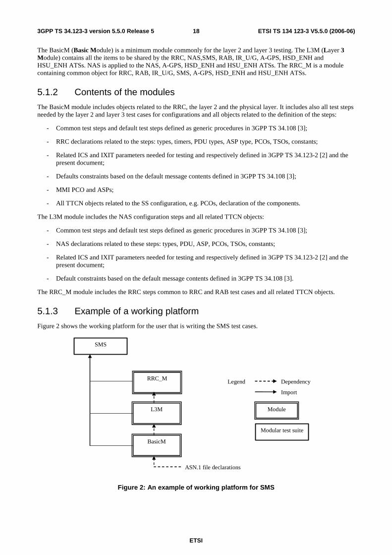
ETSI
ETSI TS 134 123-3 V5.5.0 (2006-06) 183GPP TS 34.123-3 version 5.5.0 Release 5
The BasicM (Basic Module) is a minimum module commonly for the layer 2 and layer 3 testing. The L3M (Layer 3 Module) contains all the items to be shared by the RRC, NAS,SMS, RAB, IR_U/G, A-GPS, HSD_ENH and HSU_ENH ATSs. NAS is applied to the NAS, A-GPS, HSD_ENH and HSU_ENH ATSs. The RRC_M is a module containing common object for RRC, RAB, IR_U/G, SMS, A-GPS, HSD_ENH and HSU_ENH ATSs.
5.1.2 Contents of the modules
The BasicM module includes objects related to the RRC, the layer 2 and the physical layer. It includes also all test steps needed by the layer 2 and layer 3 test cases for configurations and all objects related to the definition of the steps:
- Common test steps and default test steps defined as generic procedures in 3GPP TS 34.108 [3];
- RRC declarations related to the steps: types, timers, PDU types, ASP type, PCOs, TSOs, constants;
- Related ICS and IXIT parameters needed for testing and respectively defined in 3GPP TS 34.123-2 [2] and the present document;
- Defaults constraints based on the default message contents defined in 3GPP TS 34.108 [3];
- MMI PCO and ASPs;
- All TTCN objects related to the SS configuration, e.g. PCOs, declaration of the components.
The L3M module includes the NAS configuration steps and all related TTCN objects:
- Common test steps and default test steps defined as generic procedures in 3GPP TS 34.108 [3];
- NAS declarations related to these steps: types, PDU, ASP, PCOs, TSOs, constants;
- Related ICS and IXIT parameters needed for testing and respectively defined in 3GPP TS 34.123-2 [2] and the present document;
- Default constraints based on the default message contents defined in 3GPP TS 34.108 [3].
The RRC_M module includes the RRC steps common to RRC and RAB test cases and all related TTCN objects.
5.1.3 Example of a working platform
Figure 2 shows the working platform for the user that is writing the SMS test cases.
L3M
BasicM
ASN.1 file declarations
SMS
Dependency
Import
Module
Modular test suite
Legend RRC_M
Figure 2: An example of working platform for SMS
ETSI
ETSI TS 134 123-3 V5.5.0 (2006-06) 193GPP TS 34.123-3 version 5.5.0 Release 5
6 Test method and testing architecture
6.1 Test method The distributed single party test method is used for the UE testing. The lower tester configures the emulator and communicates with the UE under test via the emulator. An upper tester interfaces UE as (E)MMI.
All common parts in 3GPP TS 34.108 [3], 3GPP TS 34.109 [4] and 3GPP TS 34.123-2 [2] are developed in a TTCN library including the declarations, default constraints, preambles and postambles. They have the following characteristics:
- Very complex;
- Worked in different layers;
- Including data representing the radio parameters for SS setting and the data representing the UE capabilities (PICS parameters);
- Including the generic procedures to bring the UE into certain test states or a test mode (C-plane);
- Setting RABs at U-plane and SRBs in C-plane;
- Being used by every test cases no matter which layer the test case belongs to;
- No affect on the test verdict of PASS or FAIL.
The layer-specific test cases have the characteristics:
- relatively simple and straight forward;
- having narrow test scope and test purposes;
- test scenarios in a single layer (one PCO);
- assigning the test verdict.

ETSI
ETSI TS 134 123-3 V5.5.0 (2006-06) 203GPP TS 34.123-3 version 5.5.0 Release 5
6.2 Testing architecture A unique testing architecture is shown in figure 3.
AM/UM/TM PCOs
PCO CPHY
UE (SUT)
UT
EMMI, AT coms
PHY LT
Dc PCO
CC, MM, SM, GMM SMS RRC RLC MAC BMC PDCP RAB IR_U/G A-GPS HSD_ENH HSU_ENH
TTCN test cases
PCO CRLC
PCO CMAC MAC
RLC
RRC Direct Transfer
PCO UT
Figure 3: A unique testing architecture
6.2.1 Lower Tester (LT)
The Lower Tester (LT) provides the test means for the execution of the test cases for CC, SM, MM, GMM, SMS, RRC, RLC, MAC, PDCP, BMC, RAB, IR_U/G, A-GPS, HSD_ENH or HSU_ENH. The LT provides also the RLC, MAC and PHY emulators to communicate with the UE. The configuration and initialization of the emulators are control by the TTCN via ASPs.
6.2.2 Configuration and initialization
A number of TTCN test steps are designed for the generic setting.
1) Configuration of L1 of the tester, such as the cells, Physical channels and common transport channels via CPHY-PCO, configuration of MAC via CMAC-PCO and configuration of RLC layer via CRLC-PCO.
2) Sending system information via TR-PCO.
3) Establishment RRC connection via AM or UM-PCO.
4) Assigning a radio bearer via AM-PCO.
5) MM /GMM registration via Dc-PCO.
6) Establishment of a CS call or a PDP context via Dc-PCO.
7) Setting security parameters and control of integrity via CRLC- and ciphering via CRLC- and CMAC-PCO.

ETSI
ETSI TS 134 123-3 V5.5.0 (2006-06) 213GPP TS 34.123-3 version 5.5.0 Release 5
6.2.3 Upper Tester (UT)
An Upper Tester (UT) exists in the test system. The UT interfaces toward UE with any optional EMMI (3GPP TS 34.109 [4], clause 7). TTCN communicates with the UT by passing coordination primitives via a Ut PCO. The primitives can either contain AT commands aiming at the automatic tests, or some informal commands as MMI, in order to request the UE for certain actions and to provide simple means for observations of UE.
6.2.4 TTCN
TTCN is used as specification language based on TR 101 666 [27] (TTCN 2++). The importation of ASN.1 modules and modular TTCN are two of the most important features used in the design of the ATSs.
The TTCN test suites have been designed to maximize the portability from the language TTCN 2 to TTCN 3.
6.2.5 Model extension
If a test case needs to handle a concurrent situation two or more LTs can be configured at the same time. The following test scenarios identified may require multiple testers in the test configuration.
6.2.6 Multiplexing of RLC services
For the RRC and NAS testing, the TTCN RRC test steps (on RB1 and RB2) and the RRC emulator (on RB3 and RB4 for the NAS messages) share the same service access point (AM SAP). The RLC emulator shall provide separate message queues (buffers) for the TTCN RRC test steps and the RRC emulator for the TTCN NAS test cases, according to the signalling radio bearer identities.
6.3 NAS test method and architecture
6.3.1 Test configuration
The NAS test method is shown in figure 4.
UE
AM UM TM PCOs
Actions
CMAC PCO
CPHY PCO
NAS TTCN
Dc PCO
CRLC PCO
RRC Direct Transfer
Upper Tester e.g. MMI, EMMI commands
Physical A/I
MAC
RLC RLC
MAC
RRC
NAS (IUT)
UT PCO
Figure 4: NAS testing architecture
The single layer distributed test method is used.
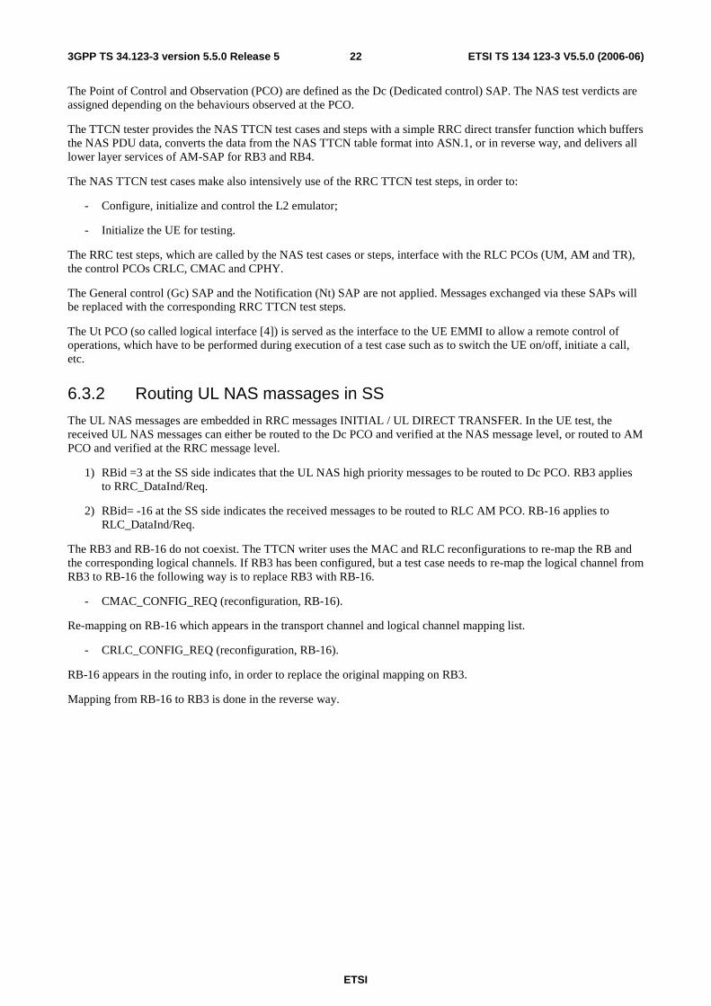
ETSI
ETSI TS 134 123-3 V5.5.0 (2006-06) 223GPP TS 34.123-3 version 5.5.0 Release 5
The Point of Control and Observation (PCO) are defined as the Dc (Dedicated control) SAP. The NAS test verdicts are assigned depending on the behaviours observed at the PCO.
The TTCN tester provides the NAS TTCN test cases and steps with a simple RRC direct transfer function which buffers the NAS PDU data, converts the data from the NAS TTCN table format into ASN.1, or in reverse way, and delivers all lower layer services of AM-SAP for RB3 and RB4.
The NAS TTCN test cases make also intensively use of the RRC TTCN test steps, in order to:
- Configure, initialize and control the L2 emulator;
- Initialize the UE for testing.
The RRC test steps, which are called by the NAS test cases or steps, interface with the RLC PCOs (UM, AM and TR), the control PCOs CRLC, CMAC and CPHY.
The General control (Gc) SAP and the Notification (Nt) SAP are not applied. Messages exchanged via these SAPs will be replaced with the corresponding RRC TTCN test steps.
The Ut PCO (so called logical interface [4]) is served as the interface to the UE EMMI to allow a remote control of operations, which have to be performed during execution of a test case such as to switch the UE on/off, initiate a call, etc.
6.3.2 Routing UL NAS massages in SS
The UL NAS messages are embedded in RRC messages INITIAL / UL DIRECT TRANSFER. In the UE test, the received UL NAS messages can either be routed to the Dc PCO and verified at the NAS message level, or routed to AM PCO and verified at the RRC message level.
1) RBid =3 at the SS side indicates that the UL NAS high priority messages to be routed to Dc PCO. RB3 applies to RRC_DataInd/Req.
2) RBid= -16 at the SS side indicates the received messages to be routed to RLC AM PCO. RB-16 applies to RLC_DataInd/Req.
The RB3 and RB-16 do not coexist. The TTCN writer uses the MAC and RLC reconfigurations to re-map the RB and the corresponding logical channels. If RB3 has been configured, but a test case needs to re-map the logical channel from RB3 to RB-16 the following way is to replace RB3 with RB-16.
- CMAC_CONFIG_REQ (reconfiguration, RB-16).
Re-mapping on RB-16 which appears in the transport channel and logical channel mapping list.
- CRLC_CONFIG_REQ (reconfiguration, RB-16).
RB-16 appears in the routing info, in order to replace the original mapping on RB3.
Mapping from RB-16 to RB3 is done in the reverse way.
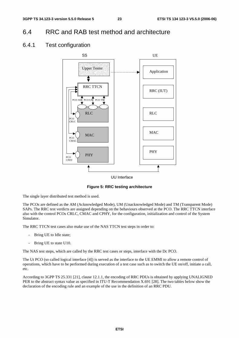
ETSI
ETSI TS 134 123-3 V5.5.0 (2006-06) 233GPP TS 34.123-3 version 5.5.0 Release 5
6.4 RRC and RAB test method and architecture
6.4.1 Test configuration
PCO UT
SS UE
UU Interface
PCO AM PCO UM PCO TM
PCO CRLC
PCO CMAC
PCO CPHY
RRC TTCN
RLC
MAC
PHY
Application
RRC (IUT)
RLC
MAC
PHY
Upper Tester
Figure 5: RRC testing architecture
The single layer distributed test method is used.
The PCOs are defined as the AM (Acknowledged Mode), UM (Unacknowledged Mode) and TM (Transparent Mode) SAPs. The RRC test verdicts are assigned depending on the behaviours observed at the PCO. The RRC TTCN interface also with the control PCOs CRLC, CMAC and CPHY, for the configuration, initialization and control of the System Simulator.
The RRC TTCN test cases also make use of the NAS TTCN test steps in order to:
- Bring UE to Idle state;
- Bring UE to state U10.
The NAS test steps, which are called by the RRC test cases or steps, interface with the Dc PCO.
The Ut PCO (so called logical interface [4]) is served as the interface to the UE EMMI to allow a remote control of operations, which have to be performed during execution of a test case such as to switch the UE on/off, initiate a call, etc.
According to 3GPP TS 25.331 [21], clause 12.1.1, the encoding of RRC PDUs is obtained by applying UNALIGNED PER to the abstract syntax value as specified in ITU-T Recommendation X.691 [28]. The two tables below show the declaration of the encoding rule and an example of the use in the definition of an RRC PDU.

ETSI
ETSI TS 134 123-3 V5.5.0 (2006-06) 243GPP TS 34.123-3 version 5.5.0 Release 5
Table 1: PER_Unaligned Encoding Rule
Encoding Rule Name PER_Unaligned Reference ITU-T Recommendation X.691 [28]
Default Comments Packet encoding rules (ITU-T Recommendation X.691 [28]) unaligned
and with adapted padding
Table 2: Definition of the RRC ASN.1 DL_DCCH_Message type by reference
PDU Name DL_DCCH_Message PCO Type DSAP
Type Reference DL-DCCH-Message Module Identifier Class-definitions
Enc Rule PER_Unaligned Enc Variation
6.4.2 RAB test method
6.4.2.1 Sending data on the same TTI
The RAB test requires a specific test method to send the test data on the same TTI. The TFC restriction method is used in this case. A specific TFC subset is allowed to ensure the test data are sent on different RBs on the same TTI. The downlink restriction can be used to ensure that the SS uses a specific TFC for transmission of data, by only allowing the "No data" TFC, and the "desired" TFC. It may also be necessary to include one or more "signalling only" TFCs to allow signalling to occur. The uplink restriction can be used to verify that the UE has used a specific TFC. Any data received by the SS using a forbidden TFCI shall be discarded.
6.4.2.2 Sending continuous data on consecutive TTIs
The RBS ATS is developed using the tabular TTCN notation. In order to test of multiple-RB combinations and simultaneous signalling, the SS shall be capable of sending continues test data in every TTI using the downlink transport format combination under test. A specific TSO is designed to request the SS sending continuous data. The information about the number of RLC SDUs and their sizes for each RAB will be provided to the system simulator through TSO.
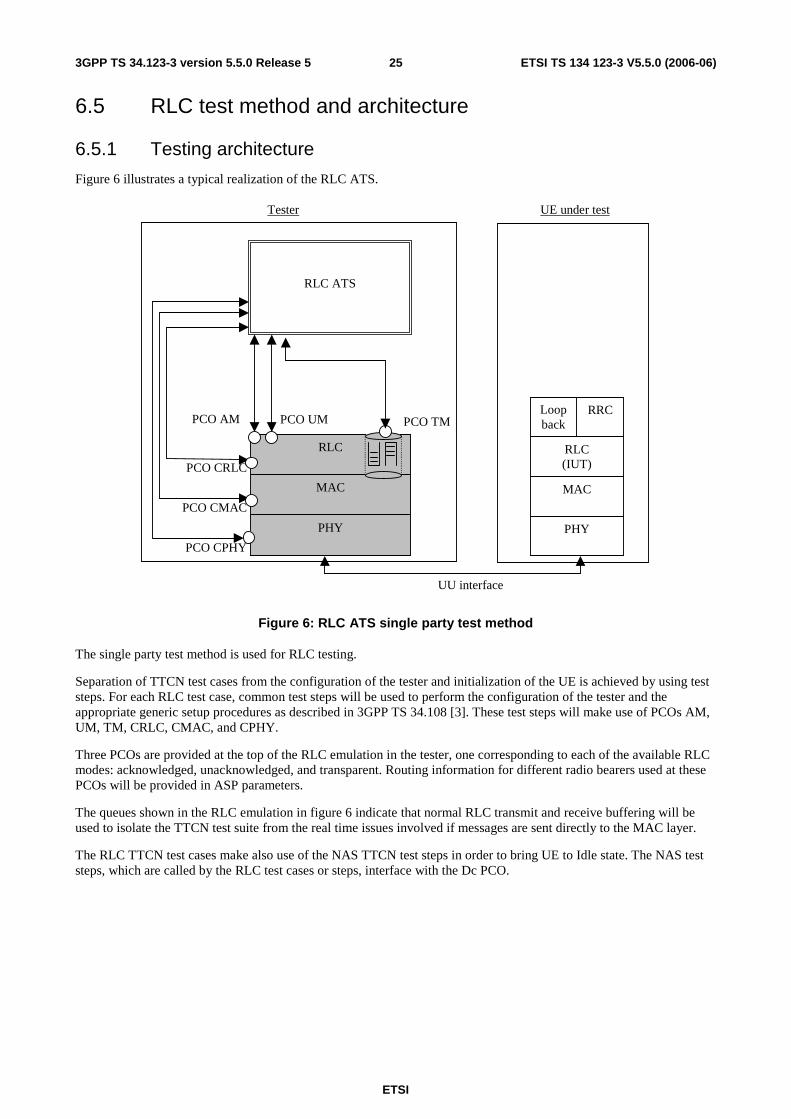
ETSI
ETSI TS 134 123-3 V5.5.0 (2006-06) 253GPP TS 34.123-3 version 5.5.0 Release 5
6.5 RLC test method and architecture
6.5.1 Testing architecture
Figure 6 illustrates a typical realization of the RLC ATS.
RLC ATS
RLC
MAC
PHY
PCO CRLC
MAC
PHY
RLC (IUT)
RRC Loop back
Tester UE under test
UU interface
PCO UM PCO AM PCO TM
PCO CMAC
PCO CPHY
Figure 6: RLC ATS single party test method
The single party test method is used for RLC testing.
Separation of TTCN test cases from the configuration of the tester and initialization of the UE is achieved by using test steps. For each RLC test case, common test steps will be used to perform the configuration of the tester and the appropriate generic setup procedures as described in 3GPP TS 34.108 [3]. These test steps will make use of PCOs AM, UM, TM, CRLC, CMAC, and CPHY.
Three PCOs are provided at the top of the RLC emulation in the tester, one corresponding to each of the available RLC modes: acknowledged, unacknowledged, and transparent. Routing information for different radio bearers used at these PCOs will be provided in ASP parameters.
The queues shown in the RLC emulation in figure 6 indicate that normal RLC transmit and receive buffering will be used to isolate the TTCN test suite from the real time issues involved if messages are sent directly to the MAC layer.
The RLC TTCN test cases make also use of the NAS TTCN test steps in order to bring UE to Idle state. The NAS test steps, which are called by the RLC test cases or steps, interface with the Dc PCO.
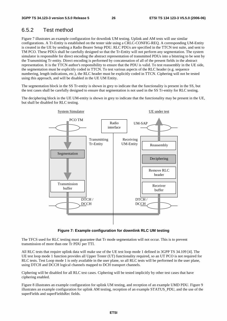
ETSI
ETSI TS 134 123-3 V5.5.0 (2006-06) 263GPP TS 34.123-3 version 5.5.0 Release 5
6.5.2 Test method
Figure 7 illustrates an example configuration for downlink UM testing. Uplink and AM tests will use similar configurations. A Tr-Entity is established on the tester side using a CRLC-CONFIG-REQ. A corresponding UM-Entity is created in the UE by sending a Radio Bearer Setup PDU. RLC PDUs are specified in the TTCN test suite, and sent to TM PCO. These PDUs shall be carefully designed so that the Tr-Entity will not perform any segmentation. The system simulator is responsible for direct encoding the abstract representation of transmitted PDUs into a bitstring to be sent by the Transmitting Tr entity. Direct encoding is performed by concatenation of all of the present fields in the abstract representation. It is the TTCN author's responsibility to ensure that the PDU is valid. To test reassembly in the UE side, the segmentation must be explicitly coded in TTCN. To test various aspects of the RLC header (e.g. sequence numbering, length indications, etc.), the RLC header must be explicitly coded in TTCN. Ciphering will not be tested using this approach, and will be disabled in the UE UM Entity.
The segmentation block in the SS Tr-entity is shown in grey to indicate that the functionality is present in the SS, but the test cases shall be carefully designed to ensure that segmentation is not used in the SS Tr-entity for RLC testing.
The deciphering block in the UE UM-entity is shown in grey to indicate that the functionality may be present in the UE, but shall be disabled for RLC testing.
PCO TM
Segmentation
Transmissionbuffer
DTCH /DCCH
Radiointerface
DTCH /DCCH
Receiverbuffer
Remove RLCheader
Deciphering
Reassembly
UM-SAP
ReceivingUM-Entity
System Simulator UE under test
TransmittingTr-Entity
Figure 7: Example configuration for downlink RLC UM testing
The TFCS used for RLC testing must guarantee that Tr mode segmentation will not occur. This is to prevent transmission of more than one Tr PDU per TTI.
All RLC tests that require uplink data will make use of the UE test loop mode 1 defined in 3GPP TS 34.109 [4]. The UE test loop mode 1 function provides all Upper Tester (UT) functionality required, so an UT PCO is not required for RLC tests. Test Loop mode 1 is only available in the user plane, so all RLC tests will be performed in the user plane, using DTCH and DCCH logical channels mapped to DCH transport channels.
Ciphering will be disabled for all RLC test cases. Ciphering will be tested implicitly by other test cases that have ciphering enabled.
Figure 8 illustrates an example configuration for uplink UM testing, and reception of an example UMD PDU. Figure 9 illustrates an example configuration for uplink AM testing, reception of an example STATUS_PDU, and the use of the superFields and superFieldsRec fields.
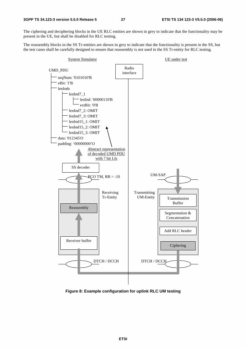
ETSI
ETSI TS 134 123-3 V5.5.0 (2006-06) 273GPP TS 34.123-3 version 5.5.0 Release 5
The ciphering and deciphering blocks in the UE RLC entities are shown in grey to indicate that the functionality may be present in the UE, but shall be disabled for RLC testing.
The reassembly blocks in the SS Tr-entities are shown in grey to indicate that the functionality is present in the SS, but the test cases shall be carefully designed to ensure that reassembly is not used in the SS Tr-entity for RLC testing.
PCO TM, RB = -10
Reassembly
Receiver buffer
DTCH / DCCH
Radio interface
DTCH / DCCH
Add RLC header
Segmentation & Concatenation
Transmission Buffer
UM-SAP
Transmitting UM-Entity
System Simulator UE under test
Receiving Tr-Entity
SS decoder
seqNum: '0101010'B
UMD_PDU
eBit: '1'B lenInds
lenInd7_1 lenInd: '00000110'B extBit: '0'B
lenInd7_2: OMIT lenInd7_3: OMIT lenInd15_1: OMIT lenInd15_2: OMIT lenInd15_3: OMIT
data: '012345'O padding: ‘00000000’O
Abstract representation of decoded UMD PDU
with 7 bit LIs
Ciphering
Figure 8: Example configuration for uplink RLC UM testing
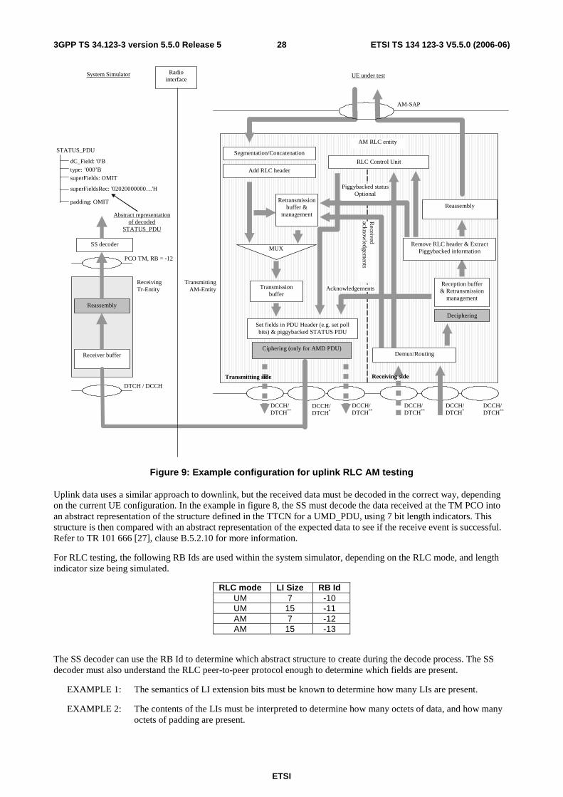
ETSI
ETSI TS 134 123-3 V5.5.0 (2006-06) 283GPP TS 34.123-3 version 5.5.0 Release 5
PCO TM, RB = -12
Reassembly
Receiver buffer
DTCH / DCCH
Radio interface
Transmitting AM-Entity
System Simulator UE under test
Receiving Tr-Entity
SS decoder
dC_Field: '0'B
STATUS_PDU
type: ‘000’B superFields: OMIT
superFieldsRec: '02020000000…'H
padding: OMIT
Abstract representation of decoded
STATUS_PDU
Transmission buffer
Retransmission buffer &
management
MUX
Set fields in PDU Header (e.g. set poll bits) & piggybacked STATUS PDU
RLC Control Unit
Received
acknowledgem
ents
Acknowledgements
DCCH/ DTCH*
AM-SAP
DCCH/ DTCH**
DCCH/ DTCH**
AM RLC entity
Demux/Routing
DCCH/ DTCH*
DCCH/DTCH**
DCCH/ DTCH**
Reception buffer & Retransmission
management
Receiving side
Segmentation/Concatenation
Ciphering (only for AMD PDU)
Add RLC header
Reassembly
Deciphering
Remove RLC header & Extract Piggybacked information
Piggybacked status Optional
Transmitting side
Figure 9: Example configuration for uplink RLC AM testing
Uplink data uses a similar approach to downlink, but the received data must be decoded in the correct way, depending on the current UE configuration. In the example in figure 8, the SS must decode the data received at the TM PCO into an abstract representation of the structure defined in the TTCN for a UMD_PDU, using 7 bit length indicators. This structure is then compared with an abstract representation of the expected data to see if the receive event is successful. Refer to TR 101 666 [27], clause B.5.2.10 for more information.
For RLC testing, the following RB Ids are used within the system simulator, depending on the RLC mode, and length indicator size being simulated.
RLC mode LI Size RB Id UM 7 -10 UM 15 -11 AM 7 -12 AM 15 -13
The SS decoder can use the RB Id to determine which abstract structure to create during the decode process. The SS decoder must also understand the RLC peer-to-peer protocol enough to determine which fields are present.
EXAMPLE 1: The semantics of LI extension bits must be known to determine how many LIs are present.
EXAMPLE 2: The contents of the LIs must be interpreted to determine how many octets of data, and how many octets of padding are present.
ETSI
ETSI TS 134 123-3 V5.5.0 (2006-06) 293GPP TS 34.123-3 version 5.5.0 Release 5
The SUFI list and any subsequent padding in a received STATUS_PDU or PiggyBackedSTATUS_PDU shall be decoded as a HEXSTRING, and put in the 'superFieldsRec' field of the abstract representation of the STATUS PDU. The "superFields" and "padding" fields shall be omitted for received STATUS PDUs. This is illustrated in figure 9.
As in downlink testing, the TFCS must be defined to guarantee that the Tr entity does not perform any reassembly. This is to prevent reception of more than one Tr PDU per TTI so that the TTCN does not need to manage possible interleaving problems due to multiple PDUs received at the same time (i.e. they may be placed on the PCO queue in any order).
6.5.2.1 Handling SUFIs in TTCN
The SUFIs are a very flexible set of information elements contained in the RLC protocol. The order of the fields varies, the existence of a field may depend upon the presence of another one. A field can be present multiple times. For matching received SUFIs, it is convenient to define the SUFIs as a HEXSTRING which is treated by a TSO o_SUFI_Handler.
Depending upon which SUFIs and which aspects of SUFIs are to be checked, the TSO is provided with the information (SUFI_Params) on what checking it is expected to perform. If the check is successful the result TRUE will be returned, otherwise FALSE. Additionally the TSO will return an object which is structured as the SUFIs used in transmission (SuperFields). This will allow to make use of information received and needed to establish SUFIs to be transmitted.
The input parameters to o_SUFI_Handler to be used as checking criteria are collected in tabular data structure SUFI_Params which is filled each time before the TSO is called. These data are to allow the checking of the presence and the value of SUFIs. All entries shall be set to well-defined values if these are to be used by o_SUFI_Handler. As a principle values specifically set are used as criteria for checking, values omitted are used as AnyOrOmit values. The resulting SUFI list is established by o_SUFI_Handler and can be retrieved in the data structure returned by the TSO. Details have to be defined in the TSO itself.
Tasks o_SUFI_Handler has to perform:
- Transfer the SUFIs received into the structure of SuperFields; this is the SUFI list structure existing today.
- If multiple occurrences of SUFI are found then use the last one to fill the SuperFields structure. The LIST SUFI is an exception: multiple SUFIs may be used to transfer the complete LIST information.
- Check for all parameters in SUFI_Params set to a specific expected value that one of the SUFIs using this value is present and that the value received matches the specific expected value.
- Check that if SUFIs are received for which an expected value of Any is specified, the SUFI is consistent if that SUFI is received.
- Check that if SUFIs are received for the presence of which no entry is specified in SUFI_Params, the SUFI is consistent.
- Check that sequence numbers are in the range between LB and UB if specific values are set.
Entries in SUFI_Params.
Element Name Significance Comment LB Lower bound of sequence number range
Lowest SN for checking SNs acknowledged
UB Upper bound of sequence number range Highest SN for checking SNs acknowledged WSN_presence Window Size SUFI present To check the presence of the Window Size SUFI MRW_presence Move Receive Window SUFI present To check the presence of the MRW SUFI
Nack1 SN of 1st PDU negatively acknowledged For the NackList to check SN to be negatively acknowledged
Nack2 SN of 2nd PDU negatively acknowledged For the NackList to check SN to be negatively acknowledged
Nack3 SN of 3rd PDU negatively acknowledged For the NackList to check SN to be negatively acknowledged
More entries may be required in the future if specific SUFI field values are to be checked. The concept allows to add more fields easily.

ETSI
ETSI TS 134 123-3 V5.5.0 (2006-06) 303GPP TS 34.123-3 version 5.5.0 Release 5
6.5.2.2 Guideline for RLC test execution
RLC tests are the Layer 2 test and they are independent of the CS or PS domain applied for the test execution. The current RLC tests are written in TTCN in the way that the test bodies of the CS and PS domains have the identical test procedures. It is sufficient to perform RLC tests in the PS domain, unless the UE supports only CS domain. In the latter case, RLC tests are performed in the CS domain.
6.6 SMS test method and architecture
6.6.1 SMS CS test method and architecture
The test method used for SMS CS tests is the same as the NAS test method, see clause 6.3, and the same ASPs, see clause 7.1.2.
6.6.2 SMS PS test method and architecture
The test method used for SMS PS tests is the same as the NAS test method, see clause 6.3, and the same ASPs, see clause 7.1.2.
6.6.3 SMS Cell broadcasting test method and architecture
The test method used for SMS CB tests is the same as the BMC test method, see clause 6.8, and the same ASPs, see clause 7.3.1.1.
6.7 MAC test method and architecture
6.7.1 Testing architecture
Figure 10 illustrates a typical realization of the MAC ATS.
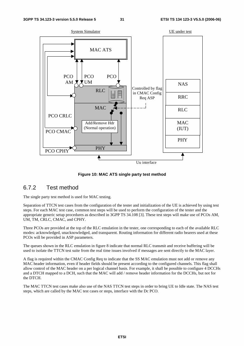
ETSI
ETSI TS 134 123-3 V5.5.0 (2006-06) 313GPP TS 34.123-3 version 5.5.0 Release 5
MAC ATS
RLC
MAC
PHY
PCO CRLC
MAC (IUT)
PHY
RLC
RRC
System Simulator UE under test
Uu interface
PCO UM
PCOAM
PCO
PCO CMAC
PCO CPHY
Add/Remove Hdr (Normal operation)
Controlled by flag in CMAC Config
Req ASP
NAS
Figure 10: MAC ATS single party test method
6.7.2 Test method
The single party test method is used for MAC testing.
Separation of TTCN test cases from the configuration of the tester and initialization of the UE is achieved by using test steps. For each MAC test case, common test steps will be used to perform the configuration of the tester and the appropriate generic setup procedures as described in 3GPP TS 34.108 [3]. These test steps will make use of PCOs AM, UM, TM, CRLC, CMAC, and CPHY.
Three PCOs are provided at the top of the RLC emulation in the tester, one corresponding to each of the available RLC modes: acknowledged, unacknowledged, and transparent. Routing information for different radio bearers used at these PCOs will be provided in ASP parameters.
The queues shown in the RLC emulation in figure 8 indicate that normal RLC transmit and receive buffering will be used to isolate the TTCN test suite from the real time issues involved if messages are sent directly to the MAC layer.
A flag is required within the CMAC Config Req to indicate that the SS MAC emulation must not add or remove any MAC header information, even if header fields should be present according to the configured channels. This flag shall allow control of the MAC header on a per logical channel basis. For example, it shall be possible to configure 4 DCCHs and a DTCH mapped to a DCH, such that the MAC will add / remove header information for the DCCHs, but not for the DTCH.
The MAC TTCN test cases make also use of the NAS TTCN test steps in order to bring UE to Idle state. The NAS test steps, which are called by the MAC test cases or steps, interface with the Dc PCO.
ETSI
ETSI TS 134 123-3 V5.5.0 (2006-06) 323GPP TS 34.123-3 version 5.5.0 Release 5
For MAC testing, the following RB Ids are used for the high priority NAS RB within the system simulator depending on the MAC configuration being simulated.
RB Id Simulated configuration -14 DCCH mapped to FACH -15 DCCH mapped to DCH -18 CCCH mapped to FACH
The SS decoder can use the RB Id to determine which MAC header fields are present, and create the appropriate abstract structure during the decode process. The SS decoder must understand enough of the MAC peer-to-peer protocol to determine which fields are present.
For example, the semantics of the UE Id Type field must be known to determine how many bits should be present in the UE Id field.
The MAC PDUs for MAC testing will always contain an AM RLC PDU (data or status) using 7 bit length indicators. See the RLC test method for further information on the SS decoder requirements for RLC PDUs.
Ciphering shall be disabled for all MAC tests.
6.7.2.1 Abnormal decoding situations
If the SS decoder cannot convert the received data into the supported structure, the SS shall terminate the test case immediately and indicate that a test case error has occurred.
6.7.2.2 MAC_es/e test method (Rel-6 or later)
MAC test method for MAC_es/e is depictured in the following figure. In the UE side the RLC entity is AM mode, in the SS the mode of RLC in downlink direction is TM, the AM mode functions are implemented in TTCN. In the uplink direction, only the mapping between RB identity and logical channel identity (i.e. the sS_rlc_Info in RBInfo is OMITTED) is configured in the RLC entity, the RLC entity passes any data block received on the logical channel to the RB identified by tsc_RB_DTCH_E_DCH_MAC(value is -20), tsc_RB_DTCH_E_DCH_MAC1(-21), or tsc_RB_DTCH_E_DCH_MAC2(-22). Whenever a RLC pdu received through one of the specified RB identifiers, the TTCN shall generate a RLC ack for it and send it on the downlink direction.

ETSI
ETSI TS 134 123-3 V5.5.0 (2006-06) 333GPP TS 34.123-3 version 5.5.0 Release 5
MAC-es/e
AM-RLC
UE
MAC-d / MAC_hs
MAC-es/e
TM-RLC
TTCN code
SS
RLC_MACes_DATA_IND RLC_TM_DATA_REQ
Physical layer
Physical layer
RAB loop back
tsc_RB_DTCH_E_DCH_MAC0(-20)
TM-RLC
CMAC_MACes_SI_IND
MAC-d / MAC_hs
Figure 11: MAC_es/e testing model
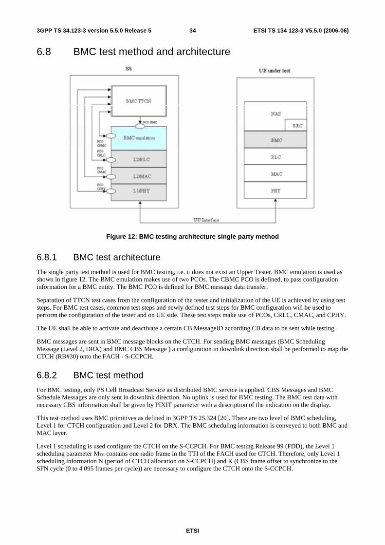
ETSI
ETSI TS 134 123-3 V5.5.0 (2006-06) 343GPP TS 34.123-3 version 5.5.0 Release 5
6.8 BMC test method and architecture
Figure 12: BMC testing architecture single party method
6.8.1 BMC test architecture
The single party test method is used for BMC testing, i.e. it does not exist an Upper Tester. BMC emulation is used as shown in figure 12. The BMC emulation makes use of two PCOs. The CBMC PCO is defined, to pass configuration information for a BMC entity. The BMC PCO is defined for BMC message data transfer.
Separation of TTCN test cases from the configuration of the tester and initialization of the UE is achieved by using test steps. For BMC test cases, common test steps and newly defined test steps for BMC configuration will be used to perform the configuration of the tester and on UE side. These test steps make use of PCOs, CRLC, CMAC, and CPHY.
The UE shall be able to activate and deactivate a certain CB MessageID according CB data to be sent while testing.
BMC messages are sent in BMC message blocks on the CTCH. For sending BMC messages (BMC Scheduling Message (Level 2, DRX) and BMC CBS Message ) a configuration in downlink direction shall be performed to map the CTCH (RB#30) onto the FACH - S-CCPCH.
6.8.2 BMC test method
For BMC testing, only PS Cell Broadcast Service as distributed BMC service is applied. CBS Messages and BMC Schedule Messages are only sent in downlink direction. No uplink is used for BMC testing. The BMC test data with necessary CBS information shall be given by PIXIT parameter with a description of the indication on the display.
This test method uses BMC primitives as defined in 3GPP TS 25.324 [20]. There are two level of BMC scheduling, Level 1 for CTCH configuration and Level 2 for DRX. The BMC scheduling information is conveyed to both BMC and MAC layer.
Level 1 scheduling is used configure the CTCH on the S-CCPCH. For BMC testing Release 99 (FDD), the Level 1 scheduling parameter MTTI contains one radio frame in the TTI of the FACH used for CTCH. Therefore, only Level 1 scheduling information N (period of CTCH allocation on S-CCPCH) and K (CBS frame offset to synchronize to the SFN cycle (0 to 4 095 frames per cycle)) are necessary to configure the CTCH onto the S-CCPCH.
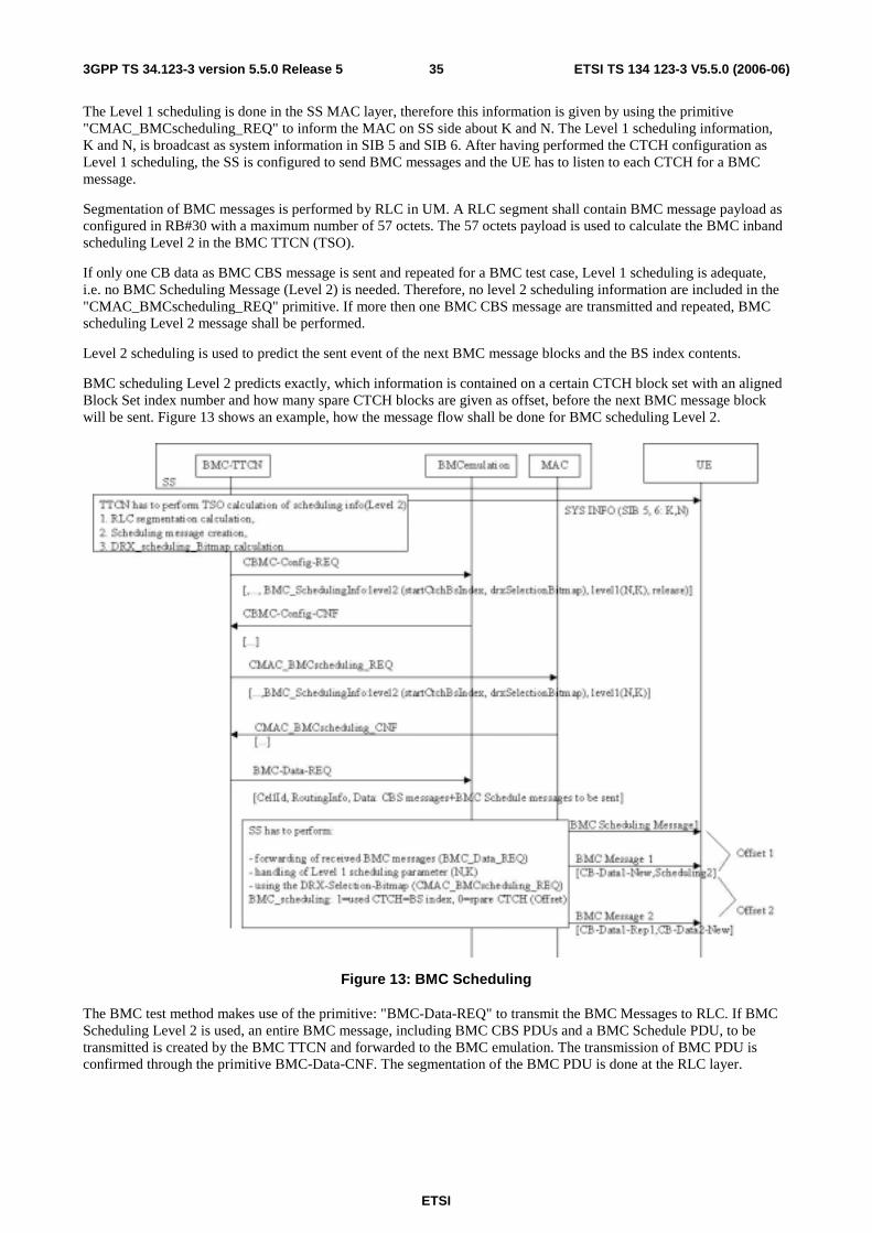
ETSI
ETSI TS 134 123-3 V5.5.0 (2006-06) 353GPP TS 34.123-3 version 5.5.0 Release 5
The Level 1 scheduling is done in the SS MAC layer, therefore this information is given by using the primitive "CMAC_BMCscheduling_REQ" to inform the MAC on SS side about K and N. The Level 1 scheduling information, K and N, is broadcast as system information in SIB 5 and SIB 6. After having performed the CTCH configuration as Level 1 scheduling, the SS is configured to send BMC messages and the UE has to listen to each CTCH for a BMC message.
Segmentation of BMC messages is performed by RLC in UM. A RLC segment shall contain BMC message payload as configured in RB#30 with a maximum number of 57 octets. The 57 octets payload is used to calculate the BMC inband scheduling Level 2 in the BMC TTCN (TSO).
If only one CB data as BMC CBS message is sent and repeated for a BMC test case, Level 1 scheduling is adequate, i.e. no BMC Scheduling Message (Level 2) is needed. Therefore, no level 2 scheduling information are included in the "CMAC_BMCscheduling_REQ" primitive. If more then one BMC CBS message are transmitted and repeated, BMC scheduling Level 2 message shall be performed.
Level 2 scheduling is used to predict the sent event of the next BMC message blocks and the BS index contents.
BMC scheduling Level 2 predicts exactly, which information is contained on a certain CTCH block set with an aligned Block Set index number and how many spare CTCH blocks are given as offset, before the next BMC message block will be sent. Figure 13 shows an example, how the message flow shall be done for BMC scheduling Level 2.
Figure 13: BMC Scheduling
The BMC test method makes use of the primitive: "BMC-Data-REQ" to transmit the BMC Messages to RLC. If BMC Scheduling Level 2 is used, an entire BMC message, including BMC CBS PDUs and a BMC Schedule PDU, to be transmitted is created by the BMC TTCN and forwarded to the BMC emulation. The transmission of BMC PDU is confirmed through the primitive BMC-Data-CNF. The segmentation of the BMC PDU is done at the RLC layer.

ETSI
ETSI TS 134 123-3 V5.5.0 (2006-06) 363GPP TS 34.123-3 version 5.5.0 Release 5
According to the K and N value, the MAC layer at SS side determines the CTCH blocks for the BMC use. The CTCH blocks are indexed (i = 1 ... 256). If BMC DRX is needed, the BMC scheduling Level 2 information figures out the occupancy / spare of the available CTCH blocks by using a DRX_Selection_Bitmap. In the bitmap each bit, set to '1', corresponds to an actually available CTCH block belonging to the DRX period for the SS transmission. The all occupied consecutive CTCH blocks constitutes a BMC DRX period, whilst the consecutive spared blocks indicate the DRX offset as spare CTCH slot.
Following the DRX_Selection_Bitmap, the segmented BMC messages are transmitted. Each "BMC-Data-REQ" primitive has its own aligned "CMAC_BMCscheduling _REQ" primitive, where all BMC scheduling information is predicted. An initial CTCH block index is given (startCtchBsIndex) as a start index offset.
An octet string is defined whereas each bit describes one assigned CTCH block, i.e. one BS index on the S-CCPCH.
Bitmap value:
1 (binary) = indicates a used/occupied BS index (CTCH frame, with a payload size of 57 octets) to send BMC message segments for a message block.
0 (binary) = indicates a spare BS index, i.e. unused CTCH frame, to give an UE supporting DRX the necessary information.
Figure 14: BMC DRX scheduling: segmentation handling
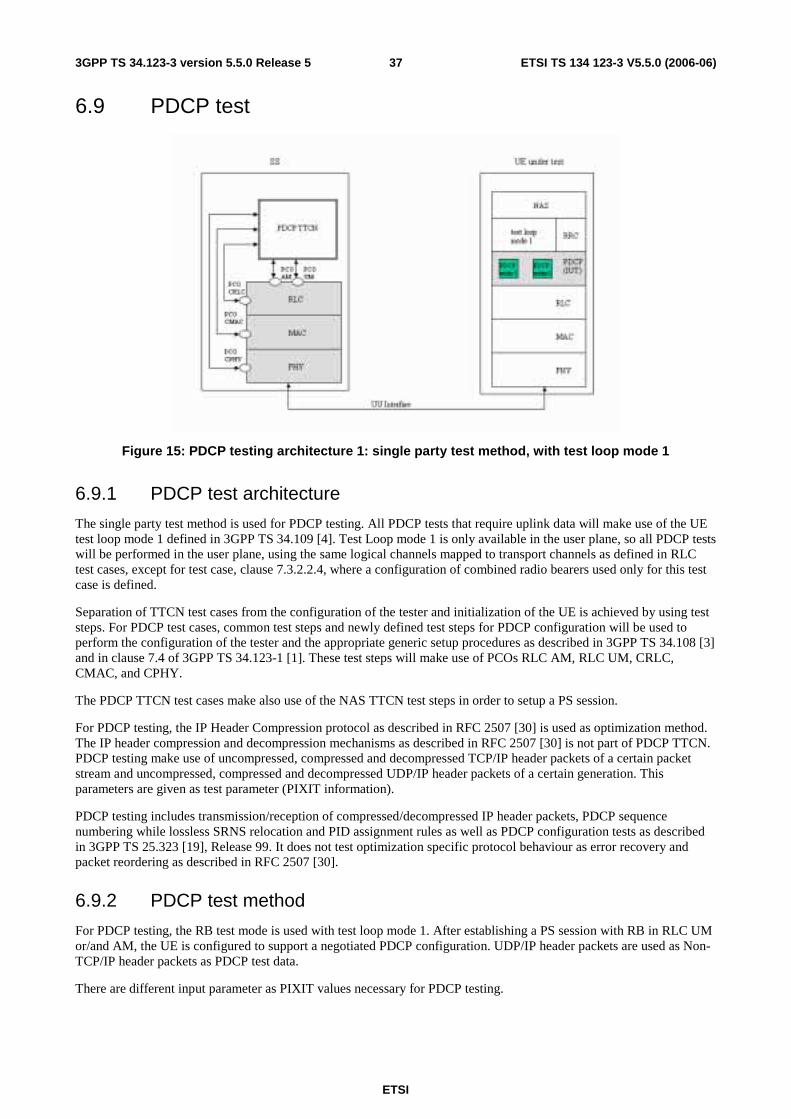
ETSI
ETSI TS 134 123-3 V5.5.0 (2006-06) 373GPP TS 34.123-3 version 5.5.0 Release 5
6.9 PDCP test
Figure 15: PDCP testing architecture 1: single party test method, with test loop mode 1
6.9.1 PDCP test architecture
The single party test method is used for PDCP testing. All PDCP tests that require uplink data will make use of the UE test loop mode 1 defined in 3GPP TS 34.109 [4]. Test Loop mode 1 is only available in the user plane, so all PDCP tests will be performed in the user plane, using the same logical channels mapped to transport channels as defined in RLC test cases, except for test case, clause 7.3.2.2.4, where a configuration of combined radio bearers used only for this test case is defined.
Separation of TTCN test cases from the configuration of the tester and initialization of the UE is achieved by using test steps. For PDCP test cases, common test steps and newly defined test steps for PDCP configuration will be used to perform the configuration of the tester and the appropriate generic setup procedures as described in 3GPP TS 34.108 [3] and in clause 7.4 of 3GPP TS 34.123-1 [1]. These test steps will make use of PCOs RLC AM, RLC UM, CRLC, CMAC, and CPHY.
The PDCP TTCN test cases make also use of the NAS TTCN test steps in order to setup a PS session.
For PDCP testing, the IP Header Compression protocol as described in RFC 2507 [30] is used as optimization method. The IP header compression and decompression mechanisms as described in RFC 2507 [30] is not part of PDCP TTCN. PDCP testing make use of uncompressed, compressed and decompressed TCP/IP header packets of a certain packet stream and uncompressed, compressed and decompressed UDP/IP header packets of a certain generation. This parameters are given as test parameter (PIXIT information).
PDCP testing includes transmission/reception of compressed/decompressed IP header packets, PDCP sequence numbering while lossless SRNS relocation and PID assignment rules as well as PDCP configuration tests as described in 3GPP TS 25.323 [19], Release 99. It does not test optimization specific protocol behaviour as error recovery and packet reordering as described in RFC 2507 [30].
6.9.2 PDCP test method
For PDCP testing, the RB test mode is used with test loop mode 1. After establishing a PS session with RB in RLC UM or/and AM, the UE is configured to support a negotiated PDCP configuration. UDP/IP header packets are used as Non-TCP/IP header packets as PDCP test data.
There are different input parameter as PIXIT values necessary for PDCP testing.
ETSI
ETSI TS 134 123-3 V5.5.0 (2006-06) 383GPP TS 34.123-3 version 5.5.0 Release 5
For TCP/IP header packets, uncompressed TCP/IP header packets shall be defined as PIXIT input parameter. In addition, there are the corresponding RFC 2507 [30] FULL_HEADER packet, COMPRESSED_TCP packet and COMPRESSED_TCP_NONDELTA packet given for each TCP/IP header packet as PIXIT information.
For UDP/IP header packets, uncompressed UDP/IP header packets shall be defined as PIXIT input parameter. In addition, there are the corresponding RFC 2507 [30] FULL_HEADER packet and COMPRESSED_NON_TCP packet given for each UDP/IP header packet as PIXIT information.
To check the use of certain PID values assigned to IP compressed header types, a given IP header packet (PIXIT) will be sent to the UE. The UE shall return a appropriate valid IP header packet type, which corresponds to the previous sent IP header packet. The usage of valid compressed/uncompressed IP header packets shall be checked by comparing the given PIXIT IP header packet types for each IP header packet previously sent.
The IP header packet order as described in RFC 2507 [30] shall be applied within a test case.
If for example an TCP/IP header packet of type "COMPRESSED_TCP" shall be sent, the TTCN uses the given TCP/IP header packet (PIXIT) for transmission to the UE. The UE shall decompress the received packets appropriate, afterwards it will be returned by the loop back entity and it shall be sent by applying IP header compression rules as described in RFC 2507 [30] and as configured. Then, the SS receives returned IP header packets and compares it with all valid IP header packets given as PIXIT parameter corresponding to the previously sent IP header packet. It is checked, whether or not the IP header packet with assigned PID is valid and a configured PDCP PDU where used for transmission. In this way, it is checked, that the UE performs IP header compression as configured and is able to assign the correct PID values.
6.10 Multi-RAT Handover Test Model
6.10.1 Overview
The test model is shown in figure 16. The SS in the model consists of UTRAN emulation part and GERAN emulation part, GERAN emulation part includes protocol emulation modules for GSM CS services and protocol emulation modules for GPRS service. Protocol stack L1 (GERAN), L2 is for GSM CS service function emulation, protocol stack L1, RLC/MAC, LLC, SNDCP is for GPRS service function emulation. SNDCP emulation model and relevant PCO's can be removed if "traffic channel gets through" is not tested.
L1 (GERAN) provides necessary physical layer functionality for both GSM and GPRS. A control PCO and a set of ASP's are defined for configuring and controlling its protocol behaviour required in the test cases. L1 (GERAN) provides services to L2 and RLC/MAC emulation modules, the interfaces between them are not specified in this test model, it is implementation dependent and shall follow the relevant GSM and GPRS specifications.
L2 emulates necessary GSM L2 protocol functionality used in testing. A data PCO and a set of ASP's are defined for this module and used for transmitting and receiving layer 3 signalling messages and use data. The definition of the PCO and these ASP's are based on the logical channel concept of GSM specification. A control PCO and related ASP's are also defined for L2, they are used to introduce abnormal layer 2 behaviour required by the test purposes.
RLC/MAC is emulation module for GPRS Radio Link Control/Medium Access Control protocol. Two PCO's and related ASP's are defined for the module. Control PCO is used to set TBF and assign physical resources to it, actual physical resources (packet channels) are created by L1 (GERAN) ASP's beforehand. Data PCO is for transmitting and receiving RLC control messages (RLC control block). Before any RLC data or control block, except RLC control block on PCCCH or PRACH, or PBCCH, is sent (or received) a proper TBF shall be configured. In addition RLC/MAC module provides service to LLC emulation module, the interface between them is determined by implementation and shall be compliant with relevant core specification.
LLC performs GPRS Logical Link Control protocol emulation. Its data PCO and ASP's are used for exchange GMM signalling messages between TTCN and the UE under test. The current defined ASP's on control PCO are subset of the primitives defined in core specification, they are used to assign, un-assign TLLI and ciphering parameters, or get status report.

ETSI
ETSI TS 134 123-3 V5.5.0 (2006-06) 393GPP TS 34.123-3 version 5.5.0 Release 5
6.10.2 ASP function description
6.10.2.1 Identities
- Within the SS, a cell is identified by cell identifier (cellId), which is of TTCN type CellId (INTEGER).
- Within a cell, a basic physical channel is identified by physical channel identifier (physicalChId), which is of TTCN type PhysicalChId (INTEGER). In multislot configuration a basic physical channel is identified by physical channel identifier (physicalChId) and timeslot, which is of TTCN type TN (INTEGER).
- Within a physical channel, logical channel is identified by logical channel type (g_LogicChType), which is of TTCN type G_LogicChType (INTEGER). When multiple logical channels of same type are carried by (mapped to) the same basic physical channel, they are differentiated by sub-channel number (subChannel), which is of TTCN type SubChannelNumber (INTEGER).
- At the top boundary of L2 emulation module two service access points (SAP) are available, they are identified by SAPI. SAPI=3 is used for short message service; SAPI=0 is used for L3 signalling messages and user data.
EXAMPLE: If G_L2_DATA_REQ ASP has the following parameter setting:
- cellId = tsc_CellA;
- sAPI = tsc_SAPI_0;
- physicalChId = tsc_PhyCh0;
- g_LogicChType = tsc_SDCCH4; and
- sunChannel = tsc_SubChannel1;
it sends PDU on the SDCCH4(1) logical channel which is carried by the physical channel tsc_PhyCh0 in cell A.
6.10.2.2 Cell configuration and control
In GSM each base station has a base station identity code BSIC, it consists of network colour code and base station colour code (NCC + BCC). BSIC is continuously broadcasted on the SCH channel, and it shall be used as the training sequence code for broadcast and common control channels.
In the test model the function of G_CL1_CreateCell_REQ ASP is to create a cell and pass parameter BSIC to it. This ASP establishes the cell identifier which shall be used in the ASP's related to this cell.
This is the first step to configure L1 (GERAN) emulation module of the SS.
6.10.2.3 L1 (GERAN) configuration and control
Configuration and control functions identified for L1 (GERAN) of a cell are:
- creation of basic physical channels;
- creation of multislot configuration;
- release of basic physical channel;
- modifications of channel mode, ciphering parameters and transmission power level;
- reporting of L1 header of SACCH channel;
- pickup a frame in near future, which can carry L3 message.
ETSI
ETSI TS 134 123-3 V5.5.0 (2006-06) 403GPP TS 34.123-3 version 5.5.0 Release 5
6.10.2.3.1 Basic physical channel configuration
A basic physical channel uses a combination of frequency and time domain resources, therefore, the definition of a particular basic physical channel consists of a description in the frequency domain and a description in the time domain. In time domain the resource is called Time Slot, there are 8 time slots in one frame, numbered from 0 to 7. In frequency domain a basic physical channel may use only one frequency or may use multiple frequencies in frequency hopping.
Basic physical channel carrying FCCH + SCH + BCCH + CCCH (PCH, AGCH, RACH) or FCCH + SCH + BCCH + CCCH + SDCCH4 logical channels shall be located in time slot 0, and uses single frequency (non-hopping). The basic physical channel carrying additional BCCH, CCCH (PCH, AGCH, RACH) logical channels shall be located in time slot 2, 4, 6 and uses the same single frequency as the frequency used by the physical channel carrying FCCH, SCH.
GSM specification defines 24 permitted combinations of different logical channels, which can be mapped on to a basic physical channel. The combination defines which logical channels are carried by a basic physical channel, and it is also an indication of which modulation (GMSK or 8PSK) is used for the basic physical channel.
Training Sequence Code (TSC) is another parameter needed by physical channel. Common control and broadcast channel have to use BCC as its TSC.
Dedicated control channel and dedicated traffic channel need more parameters to configure. Parameter "Channel Mode" is needed to specify channel coding (therefore the user data rate). Ciphering related parameters are required to define the ciphering behaviour of the channel.
Common control channels need parameters to configure where in the 51-multiframe paging and access grant blocks are located.
Transmission power level is provided as per physical channel parameter, power level of each physical channel can be controlled independently.
The function of ASP G_CL1_CreateBasicPhyCh_REQ is to create a basic physical channel which has the required property defined by all the parameters mentioned above.
In the process of L1 (GERAN) configuration, calling the ASP is the next step after calling G_CL1_CreateCell_REQ.
6.10.2.3.2 Multislot configuration for circuit or packet switched channels
Multislot configuration for circuit switched connection consists of multiple circuit switched traffic channels, in L1 point of view these traffic channels are independent basic physical channels with the same frequency parameters (ARFCN or MA, MAIO, HSN) and the same training sequence code but located in different time slots, one of the basic physical channels is the main channel of the configuration carrying the main signalling (FACCH, SACCH, IACCH) for the configuration. The main channel shall be bi-directional channel and with channelCombanition TCH/F+FACCH/F+SACCH/M or E-TCH/F+E-IACCH/F+E-FACCH/F+E-SACCH/M. When transmitting user data (not signalling message) stream is divided into substreams, each substream is transmitted independently on a channel in the configuration. At the receiving side all substreams are combined back to user stream.
According to the test model creation of a multislot configuration for circuit switched connection needs two ASP calls. Firstly, G_L1_CreatedBasicPhyCh_REQ is called to establish the main channel, then G_L1_CreateMultiSlotConfig_REQ is called to allocate more timeslots to the channel established by the previous ASP. A substream of a multislot configuration is identified with the physicalChId and timeslot.
Multislot configuration for packet switched connection consists of multiple PDCHs which can carry PDTCH/Us or PDTCH/Ds. All these PDCHs use the same frequency parameters (ARFCN or MA, MAIO, HSN) and the same training sequence code, but are located on different timeslots.
Similarly, a multislot configuration for packet switched connection is created with two ASP calls. First G_L1_CreatedBasicPhyCh_REQ is called to establish the first PDCH channel, then G_L1_CreateMultiSlotConfig_REQ is called to allocate more timeslots to the channel established by the previous ASP. All data ASP on packet data channel use physicalChId and timeslot to address the physical channels.
ETSI
ETSI TS 134 123-3 V5.5.0 (2006-06) 413GPP TS 34.123-3 version 5.5.0 Release 5
6.10.2.3.3 Frame in the near future
ASP G_CL1_ComingFN_REQ is defined to request L1 (GERAN) return the reduced frame number (FN modulo 42432) which is far enough in the future from current frame number and is able to carry L3 message on the specified channel. "far enough" means that there is enough time left for TTCN to prepare a L3 message to be sent on that frame. When calculating startingTime, this ASP could be useful. The starting time usually is set to a frame number in a time distance from current frame number. TTCN writer can use G_CL1_ComingFN_REQ to get a frame number in the future then add a certain number of frames as time distance to it and use the result as the value for startingTime.
6.10.2.3.4 L1 header
The layer 1 header of SACCH from UE to network carries information of timing advance and UE uplink transmission power level, verifying L1 header contents is required in some test cases, ASP G_CL1_L1Header_REQ and G_CL1_L1Header_CNF are defined for fulfilling this requirement.
6.10.2.4 L2 configuration and control
For normal operation there is no parameter configurable in L2. Some abnormal L2 behaviours are required in test cases. In the test model two ASP's are currently defined to introduce abnormal L2 behaviour. When creating a dedicated channel the initial SACCH header is set to the values in powerLevel and timingAdvance fields of DedCH_Info.
6.10.2.4.1 Don't response to some handover access bursts
In non-synchronized handover procedure UE/MS, having received handover command, sends handover access bursts on the target channel repeatedly till it receives PHYSICAL INFORMATION message from network or T3124 times out. Normally network replies PHYSICAL INFORMATION as soon as it receives handover access burst. Some test cases require that the SS ignores several incoming handover access bursts then responses to the one that follows. ASP G_CL2_HoldPhyInfo_REQ is defined for fulfilling this requirement. It is used together with and before a data ASP sending PHYSICAL INFORMATION message. When SS receives the G_CL2_HoldPhyInfo_REQ, it does not transmit the PHYSICAL INFORMATION message until n handover access bursts have been received.
6.10.2.4.2 No UA reply to SABM
GSM L2 protocol is adapted from LAPD (HDLC subset). The multiframe operation mode is established through exchange of supervisory frame SABM and unnumbered frame UA between peer entities, and SABM is always sent by UE/MS, UA is always sent by network. UE/MS will repeatedly transmit SABM till it receives UA or retransmission counter is reached. Some handover test cases require that the SS does not response to the incoming SABM, so handover fails. G_CL2_NoUAforSABM_REQ is used for such purpose, it commands the SS not to send UA response to the UE when SABM is received.
6.10.2.5 System Information sending
There are 17 different SYSTEM INFORMATION messages on BCCH and 4 different SYSTEM INFORMATION messages on SACCH defined for circuit switched services in GSM specification. In a particular test case not all of them are required. SYSTEM INFORMATION messages on BCCH shall be broadcasted periodically by the SS, SYSTEM INFORMATION TYPE 5, 6 and optionally 5bis and 5ter messages shall be sent on SACCH by the SS when nothing else has to be sent on that channel.
G_L2_SYSINFO_REQ is defined to deliver a SYSTEM INFORMATION message and its type SysInfoType to the SS, SS shall store the SYSTEM INFORMATION and transmit it periodically according to the scheduling rules specified in 3GPP TS 45.002 [31] clause 6.3.1.3. SYSTEM INFORMATION message newly delivered shall override the same type SYSTEM IFORMATION message previously stored in the SS.
SYSTEM INFORMATION message type 18, 19, 20 are scheduled by scheduling information in SYSTEM INFORMATION type 9. ASP for scheduling these messages has not been defined yet because these messages are not required in current test cases.

ETSI
ETSI TS 134 123-3 V5.5.0 (2006-06) 423GPP TS 34.123-3 version 5.5.0 Release 5
6.10.2.6 Paging
Paging message for a particular UE/MS shall be sent on the right CCCH_GROUP (or PCCCH_GROUP) and PAGING_GROUP which are determined by IMSI of the UE/MS and other parameters. In the test model TTCN code is responsible to calculate the value of CCCH_GROUP (or PCCCH_GROUP) and the value of PAGING_GROUP.
TTCN selects the right channel according to the value of CCCH_GROUP (or PCCCH_GROUP), then PAGING REQUEST message and the value of PAGING_GROUP are passed to the SS by using:
- ASP G_L2_Paging_REQ in case of UE/MS in idle mode or the UE/MS not supporting SPLIT_PG_CYCLE on CCCH when it is in GPRS attached mode and PCCCH is absent; or
- G_RLC_ControlMsg_REQ in case of UE/MS supporting 3GPP TS 45.002 [31] clause 6.5.6 when it is in GPRS attached mode and PCCCH is present.
The SS shall determine the position where the paging block is located using the value PAGING_GROUP and other CCCH (or PCCCH) parameters configured by G_CL1_CreateBasicPhyCH_REQ, then send the PAGING REQUEST message according the parameter pagingMode in the ASP:
- send the message on the paging block determined by PAGING_GROUP if pagingMode = "normal paging";
- send the message on the paging block determined by PAGING_GROUP and the "next but one" position on the PCH or in the third block period on PCCCH where paging may occur (PPCH) if pagingMode = "extended paging";
- send the message on all paging blocks if pagingMode ="paging reorganization".
6.10.2.7 Generic procedures for GPRS signalling
Two channel combinations are applied to configure a GERAN cell for the GPRS signalling:
- The channel combinations 5 + 13, (FCCH + SCH + BCCH + CCCH + SDCCH/4(0..3) + SACCH/C4(0..3)) + (PBCCH+PCCCH+PDTCH/F+PACCH/F+PTCCH/F), are considered as default at the interRAT tests.
- The channel combinations 5 + 11, (FCCH + SCH + BCCH + CCCH + SDCCH/4(0..3) + SACCH/C4(0..3)) + (PDTCH/F+PACCH/F+PTCCH/F), are applied to the clause 42.4.7.
The following generic procedures show the usages of GPRS ASP's for the GPRS generic attach procedures, the generic cell change order within a TBF and the GSM ciphering procedure.
6.10.2.7.1 GPRS generic attach procedures and ciphering mode control
6.10.2.7.1.1 GPRS attach procedure in channel combinations 5 and 13
Direction ASP message Comments SS G_CL1_CreateCell_REQ Create the cell SS G_CL1_CreateBasicPhyCh_REQ Create the physical channel
combination 5 for FCCH+SCH+BCCH+CCCH+SDCCH/4(0..3)+SACCH/C4(0..3)
SS G_CL1_CreateBasicPhyCh_REQ Create the physical channel combination 13 for PDTCH/F+PACCH/F+PTCCH/F
SS -> MS G_L2_SYSINFO_REQ SYSTEM INFORMATION TYPE1, SYSTEM INFORMATION TYPE2, SYSTEM INFORMATION TYPE2quater, SYSTEM INFORMATION TYPE3, SYSTEM INFORMATION TYPE4, SYSTEM INFORMATION TYPE13
Broadcast system information messages : SI 1~4; SI 13
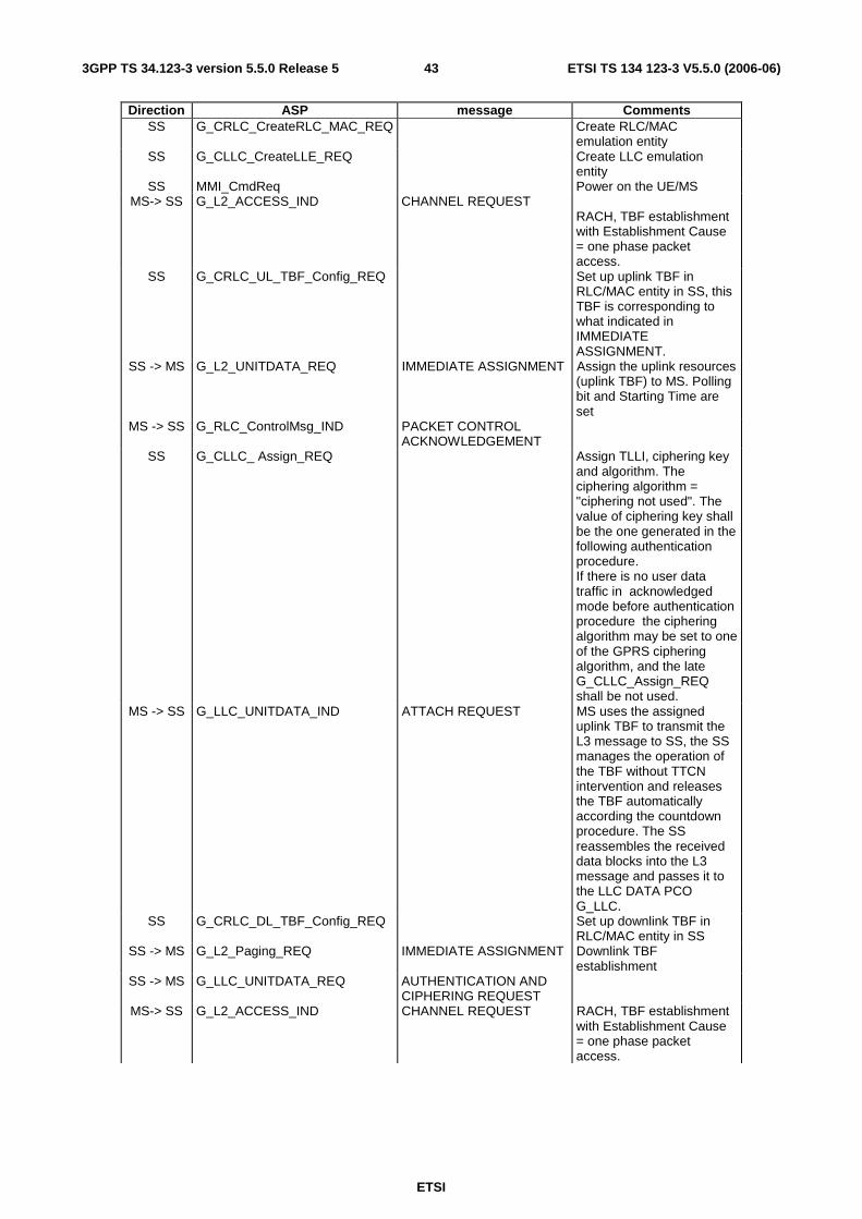
ETSI
ETSI TS 134 123-3 V5.5.0 (2006-06) 433GPP TS 34.123-3 version 5.5.0 Release 5
Direction ASP message Comments SS G_CRLC_CreateRLC_MAC_REQ Create RLC/MAC
emulation entity SS G_CLLC_CreateLLE_REQ Create LLC emulation
entity SS MMI_CmdReq Power on the UE/MS
MS-> SS G_L2_ACCESS_IND CHANNEL REQUEST RACH, TBF establishment with Establishment Cause = one phase packet access.
SS G_CRLC_UL_TBF_Config_REQ Set up uplink TBF in RLC/MAC entity in SS, this TBF is corresponding to what indicated in IMMEDIATE ASSIGNMENT.
SS -> MS G_L2_UNITDATA_REQ IMMEDIATE ASSIGNMENT Assign the uplink resources (uplink TBF) to MS. Polling bit and Starting Time are set
MS -> SS G_RLC_ControlMsg_IND PACKET CONTROL ACKNOWLEDGEMENT
SS G_CLLC_ Assign_REQ Assign TLLI, ciphering key and algorithm. The ciphering algorithm = "ciphering not used". The value of ciphering key shall be the one generated in the following authentication procedure. If there is no user data traffic in acknowledged mode before authentication procedure the ciphering algorithm may be set to one of the GPRS ciphering algorithm, and the late G_CLLC_Assign_REQ shall be not used.
MS -> SS G_LLC_UNITDATA_IND ATTACH REQUEST MS uses the assigned uplink TBF to transmit the L3 message to SS, the SS manages the operation of the TBF without TTCN intervention and releases the TBF automatically according the countdown procedure. The SS reassembles the received data blocks into the L3 message and passes it to the LLC DATA PCO G_LLC.
SS G_CRLC_DL_TBF_Config_REQ Set up downlink TBF in RLC/MAC entity in SS
SS -> MS G_L2_Paging_REQ IMMEDIATE ASSIGNMENT Downlink TBF establishment
SS -> MS G_LLC_UNITDATA_REQ AUTHENTICATION AND CIPHERING REQUEST
MS-> SS G_L2_ACCESS_IND CHANNEL REQUEST RACH, TBF establishment with Establishment Cause = one phase packet access.
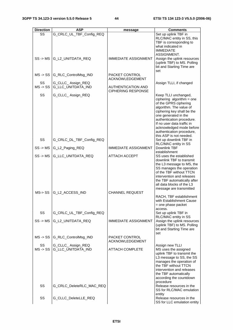
ETSI
ETSI TS 134 123-3 V5.5.0 (2006-06) 443GPP TS 34.123-3 version 5.5.0 Release 5
Direction ASP message Comments SS G_CRLC_UL_TBF_Config_REQ Set up uplink TBF in
RLC/MAC entity in SS, this TBF is corresponding to what indicated in IMMEDIATE ASSIGNMENT.
SS -> MS G_L2_UNITDATA_REQ IMMEDIATE ASSIGNMENT Assign the uplink resources (uplink TBF) to MS. Polling bit and Starting Time are set
MS -> SS G_RLC_ControlMsg_IND PACKET CONTROL ACKNOWLEDGEMENT
SS G_CLLC_ Assign_REQ Assign TLLI, if changed MS -> SS G_LLC_UNITDATA_IND AUTHENTICATION AND
CIPHERING RESPONSE
SS G_CLLC_ Assign_REQ Keep TLLI unchanged, ciphering algorithm = one of the GPRS ciphering algorithm. The value of ciphering key shall be the one generated in the authentication procedure. If no user data traffic in acknowledged mode before authentication procedure, this ASP is not needed.
SS G_CRLC_DL_TBF_Config_REQ Set up downlink TBF in RLC/MAC entity in SS
SS -> MS G_L2_Paging_REQ IMMEDIATE ASSIGNMENT Downlink TBF establishment
SS -> MS G_LLC_UNITDATA_REQ ATTACH ACCEPT SS uses the established downlink TBF to transmit the L3 message to MS, the SS manages the operation of the TBF without TTCN intervention and releases the TBF automatically after all data blocks of the L3 message are transmitted
MS-> SS G_L2_ACCESS_IND CHANNEL REQUEST RACH, TBF establishment with Establishment Cause = one phase packet access.
SS G_CRLC_UL_TBF_Config_REQ Set up uplink TBF in RLC/MAC entity in SS
SS -> MS G_L2_UNITDATA_REQ IMMEDIATE ASSIGNMENT Assign the uplink resources (uplink TBF) to MS. Polling bit and Starting Time are set
MS -> SS G_RLC_ControlMsg_IND PACKET CONTROL ACKNOWLEDGEMENT
SS G_CLLC_ Assign_REQ Assign new TLLI MS -> SS G_LLC_UNITDATA_IND ATTACH COMPLETE MS uses the assigned
uplink TBF to transmit the L3 message to SS, the SS manages the operation of the TBF without TTCN intervention and releases the TBF automatically according the countdown procedure
SS G_CRLC_DeleteRLC_MAC_REQ Release resources in the SS for RLC/MAC emulation entity
SS G_CLLC_DeleteLLE_REQ Release resources in the SS for LLC emulation entity
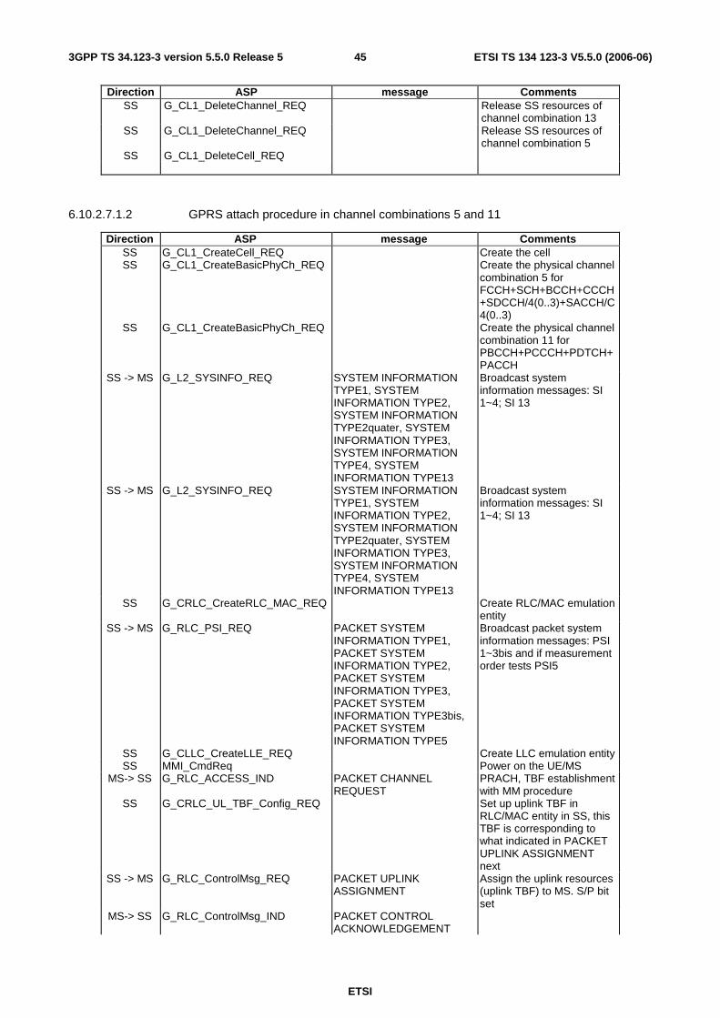
ETSI
ETSI TS 134 123-3 V5.5.0 (2006-06) 453GPP TS 34.123-3 version 5.5.0 Release 5
Direction ASP message Comments SS G_CL1_DeleteChannel_REQ Release SS resources of
channel combination 13 SS G_CL1_DeleteChannel_REQ Release SS resources of
channel combination 5 SS G_CL1_DeleteCell_REQ
6.10.2.7.1.2 GPRS attach procedure in channel combinations 5 and 11
Direction ASP message Comments SS G_CL1_CreateCell_REQ Create the cell SS G_CL1_CreateBasicPhyCh_REQ Create the physical channel
combination 5 for FCCH+SCH+BCCH+CCCH+SDCCH/4(0..3)+SACCH/C4(0..3)
SS G_CL1_CreateBasicPhyCh_REQ Create the physical channel combination 11 for PBCCH+PCCCH+PDTCH+PACCH
SS -> MS G_L2_SYSINFO_REQ SYSTEM INFORMATION TYPE1, SYSTEM INFORMATION TYPE2, SYSTEM INFORMATION TYPE2quater, SYSTEM INFORMATION TYPE3, SYSTEM INFORMATION TYPE4, SYSTEM INFORMATION TYPE13
Broadcast system information messages: SI 1~4; SI 13
SS -> MS G_L2_SYSINFO_REQ SYSTEM INFORMATION TYPE1, SYSTEM INFORMATION TYPE2, SYSTEM INFORMATION TYPE2quater, SYSTEM INFORMATION TYPE3, SYSTEM INFORMATION TYPE4, SYSTEM INFORMATION TYPE13
Broadcast system information messages: SI 1~4; SI 13
SS G_CRLC_CreateRLC_MAC_REQ Create RLC/MAC emulation entity
SS -> MS G_RLC_PSI_REQ PACKET SYSTEM INFORMATION TYPE1, PACKET SYSTEM INFORMATION TYPE2, PACKET SYSTEM INFORMATION TYPE3, PACKET SYSTEM INFORMATION TYPE3bis, PACKET SYSTEM INFORMATION TYPE5
Broadcast packet system information messages: PSI 1~3bis and if measurement order tests PSI5
SS G_CLLC_CreateLLE_REQ Create LLC emulation entity SS MMI_CmdReq Power on the UE/MS
MS-> SS G_RLC_ACCESS_IND PACKET CHANNEL REQUEST
PRACH, TBF establishment with MM procedure
SS G_CRLC_UL_TBF_Config_REQ Set up uplink TBF in RLC/MAC entity in SS, this TBF is corresponding to what indicated in PACKET UPLINK ASSIGNMENT next
SS -> MS G_RLC_ControlMsg_REQ PACKET UPLINK ASSIGNMENT
Assign the uplink resources (uplink TBF) to MS. S/P bit set
MS-> SS G_RLC_ControlMsg_IND PACKET CONTROL ACKNOWLEDGEMENT
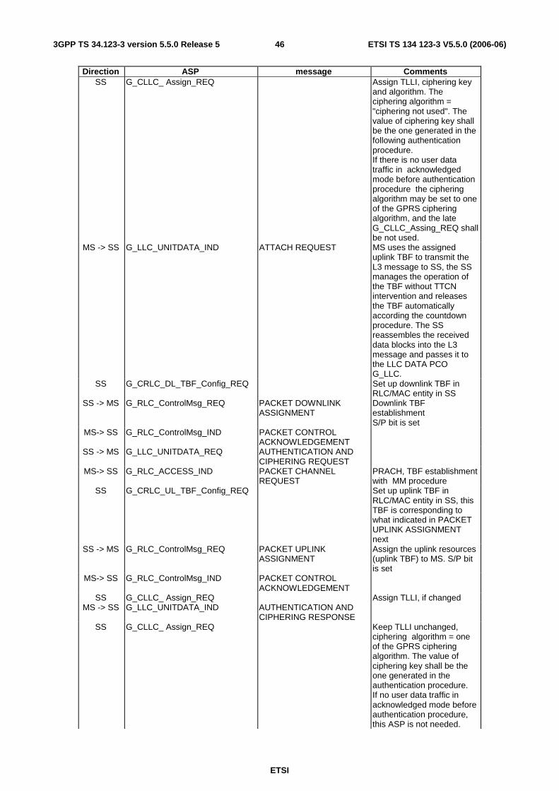
ETSI
ETSI TS 134 123-3 V5.5.0 (2006-06) 463GPP TS 34.123-3 version 5.5.0 Release 5
Direction ASP message Comments SS G_CLLC_ Assign_REQ Assign TLLI, ciphering key
and algorithm. The ciphering algorithm = "ciphering not used". The value of ciphering key shall be the one generated in the following authentication procedure. If there is no user data traffic in acknowledged mode before authentication procedure the ciphering algorithm may be set to one of the GPRS ciphering algorithm, and the late G_CLLC_Assing_REQ shall be not used.
MS -> SS G_LLC_UNITDATA_IND ATTACH REQUEST MS uses the assigned uplink TBF to transmit the L3 message to SS, the SS manages the operation of the TBF without TTCN intervention and releases the TBF automatically according the countdown procedure. The SS reassembles the received data blocks into the L3 message and passes it to the LLC DATA PCO G_LLC.
SS G_CRLC_DL_TBF_Config_REQ Set up downlink TBF in RLC/MAC entity in SS
SS -> MS G_RLC_ControlMsg_REQ PACKET DOWNLINK ASSIGNMENT
Downlink TBF establishment S/P bit is set
MS-> SS G_RLC_ControlMsg_IND PACKET CONTROL ACKNOWLEDGEMENT
SS -> MS G_LLC_UNITDATA_REQ AUTHENTICATION AND CIPHERING REQUEST
MS-> SS G_RLC_ACCESS_IND PACKET CHANNEL REQUEST
PRACH, TBF establishment with MM procedure
SS G_CRLC_UL_TBF_Config_REQ Set up uplink TBF in RLC/MAC entity in SS, this TBF is corresponding to what indicated in PACKET UPLINK ASSIGNMENT next
SS -> MS G_RLC_ControlMsg_REQ PACKET UPLINK ASSIGNMENT
Assign the uplink resources (uplink TBF) to MS. S/P bit is set
MS-> SS G_RLC_ControlMsg_IND PACKET CONTROL ACKNOWLEDGEMENT
SS G_CLLC_ Assign_REQ Assign TLLI, if changed MS -> SS G_LLC_UNITDATA_IND AUTHENTICATION AND
CIPHERING RESPONSE
SS G_CLLC_ Assign_REQ Keep TLLI unchanged, ciphering algorithm = one of the GPRS ciphering algorithm. The value of ciphering key shall be the one generated in the authentication procedure. If no user data traffic in acknowledged mode before authentication procedure, this ASP is not needed.
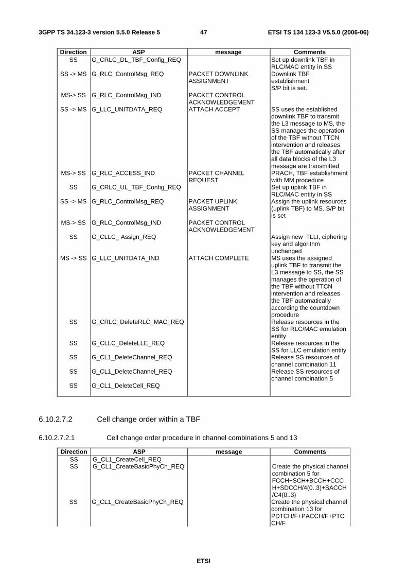
ETSI
ETSI TS 134 123-3 V5.5.0 (2006-06) 473GPP TS 34.123-3 version 5.5.0 Release 5
Direction ASP message Comments SS G_CRLC_DL_TBF_Config_REQ Set up downlink TBF in
RLC/MAC entity in SS SS -> MS G_RLC_ControlMsg_REQ PACKET DOWNLINK
ASSIGNMENT Downlink TBF establishment S/P bit is set.
MS-> SS G_RLC_ControlMsg_IND PACKET CONTROL ACKNOWLEDGEMENT
SS -> MS G_LLC_UNITDATA_REQ ATTACH ACCEPT SS uses the established downlink TBF to transmit the L3 message to MS, the SS manages the operation of the TBF without TTCN intervention and releases the TBF automatically after all data blocks of the L3 message are transmitted
MS-> SS G_RLC_ACCESS_IND PACKET CHANNEL REQUEST
PRACH, TBF establishment with MM procedure
SS G_CRLC_UL_TBF_Config_REQ Set up uplink TBF in RLC/MAC entity in SS
SS -> MS G_RLC_ControlMsg_REQ PACKET UPLINK ASSIGNMENT
Assign the uplink resources (uplink TBF) to MS. S/P bit is set
MS-> SS G_RLC_ControlMsg_IND PACKET CONTROL ACKNOWLEDGEMENT
SS G_CLLC_ Assign_REQ Assign new TLLI, ciphering key and algorithm unchanged
MS -> SS G_LLC_UNITDATA_IND ATTACH COMPLETE MS uses the assigned uplink TBF to transmit the L3 message to SS, the SS manages the operation of the TBF without TTCN intervention and releases the TBF automatically according the countdown procedure
SS G_CRLC_DeleteRLC_MAC_REQ Release resources in the SS for RLC/MAC emulation entity
SS G_CLLC_DeleteLLE_REQ Release resources in the SS for LLC emulation entity
SS G_CL1_DeleteChannel_REQ Release SS resources of channel combination 11
SS G_CL1_DeleteChannel_REQ Release SS resources of channel combination 5
SS G_CL1_DeleteCell_REQ
6.10.2.7.2 Cell change order within a TBF
6.10.2.7.2.1 Cell change order procedure in channel combinations 5 and 13
Direction ASP message Comments SS G_CL1_CreateCell_REQ SS G_CL1_CreateBasicPhyCh_REQ Create the physical channel
combination 5 for FCCH+SCH+BCCH+CCCH+SDCCH/4(0..3)+SACCH/C4(0..3)
SS G_CL1_CreateBasicPhyCh_REQ Create the physical channel combination 13 for PDTCH/F+PACCH/F+PTCCH/F

ETSI
ETSI TS 134 123-3 V5.5.0 (2006-06) 483GPP TS 34.123-3 version 5.5.0 Release 5
Direction ASP message Comments SS -> MS G_L2_SYSINFO_REQ SYSTEM INFORMATION
TYPE1, SYSTEM INFORMATION TYPE2, SYSTEM INFORMATION TYPE2quater, SYSTEM INFORMATION TYPE3, SYSTEM INFORMATION TYPE4, SYSTEM INFORMATION TYPE13
Broadcast system information messages: SI 1~4; SI 13
SS G_CRLC_CreateRLC_MAC_REQ Create RLC/MAC emulation entity
SS G_CLLC_CreateLLE_REQ Create LLC emulation entity
SS G_CLLC_ Assign_REQ Assign TLLI, ciphering key and algorithm
MS MS is GPRS attached, PDP context activated, then trigger MS to send two SNDCP PDU on LLC SAPI 3, each with 500 bytes user data.
MS-> SS G_L2_ACCESS_IND CHANNEL REQUEST RACH, TBF establishment with Establishment Cause = one phase packet access.
SS G_CRLC_UL_TBF_Config_REQ Set up uplink TBF in RLC/MAC entity in SS, this TBF is corresponding to what indicated in the next IMMEDIATE ASSIGNMENT. The USFRate is set to 5 USF per second.
SS -> MS G_L2_UNITDATA_REQ IMMEDIATE ASSIGNMENT Assign the uplink resources (uplink TBF) to MS
MS -> SS G_LLC_UNITDATA_IND User data on SAPI 3, the first SNDCP PDU
The TBF shall not be in countdown process
SS -> MS G_RLC_ControlMsg_REQ PACKET MEASUREMENT
ORDER This is within the TBF established above, which is in the process handling the second SNDCP PDU REPORT_TYPE = 1
MS -> SS G_RLC_ControlMsg_IND PACKET MEASUREMENT REPORT
MS sends the PACKET MEASUREMENT REPORT
SS -> MS G_RLC_ControlMsg_REQ PACKET CELL CHANGE ORDER
This is within the TBF established above
what follows are in UTRAN cell, not present here
6.10.2.7.2.2 Cell change order procedure in channel combinations 5 and 11
Direction ASP message Comments SS G_CL1_CreateCell_REQ SS G_CL1_CreateBasicPhyCh_REQ Create the physical channel
combination 5 for FCCH+SCH+BCCH+CCCH+SDCCH/4(0..3)+SACCH/C4(0..3)
SS G_CL1_CreateBasicPhyCh_REQ Create the physical channel combination 11 for PBCCH+PCCCH+PDTCH+PACCH

ETSI
ETSI TS 134 123-3 V5.5.0 (2006-06) 493GPP TS 34.123-3 version 5.5.0 Release 5
Direction ASP message Comments SS -> MS G_L2_SYSINFO_REQ SYSTEM INFORMATION
TYPE1, SYSTEM INFORMATION TYPE2, SYSTEM INFORMATION TYPE2quater, SYSTEM INFORMATION TYPE3, SYSTEM INFORMATION TYPE4, SYSTEM INFORMATION TYPE13
Broadcast system information messages: SI 1~4; SI 13
SS G_CRLC_CreateRLC_MAC_REQ Create RLC/MAC emulation entity
SS -> MS G_RLC_PSI_REQ PACKET SYSTEM INFORMATION TYPE1, PACKET SYSTEM INFORMATION TYPE2, PACKET SYSTEM INFORMATION TYPE3, PACKET SYSTEM INFORMATION TYPE3bis, PACKET SYSTEM INFORMATION TYPE5
Broadcast packet system information messages : PSI 1~3bis, and PSI 5
SS G_CLLC_CreateLLE_REQ Create LLC emulation entity SS G_CLLC_ Assign_REQ Assign TLLI, ciphering key
and algorithm MS MS is GPRS attached, PDP
context activated, then trigger MS to send two SNDCP PDU on LLC SAPI 3, each with 500 bytes user data.
MS-> SS G_RLC_ACCESS_IND PACKET CHANNEL REQUEST
PRACH, TBF establishment with one phase or two phase access
SS -> MS G_RLC_ControlMsg_REQ PACKET UPLINK
ASSIGNMENT PCCCH, Single block allocation
MS -> SS G_RLC_ControlMsg_IND PACKET RESOURCE
REQUEST
SS G_CRLC_UL_TBF_Config_REQ Set up uplink TBF in RLC/MAC entity in SS, this TBF is corresponding to what indicated in PACKET UPLINK ASSIGNMENT next. The USFRate is set to 5 USF per second.
SS -> MS G_RLC_ControlMsg_REQ PACKET UPLINK ASSIGNMENT
Assign the uplink resources (uplink TBF) to MS
MS -> SS G_LLC_UNITDATA_IND User data on SAPI 3, the first SNDCP PDU
The TBF shall not be in countdown process
SS -> MS G_RLC_ControlMsg_REQ PACKET MEASUREMENT
ORDER This is within the TBF established above, which is in the process handling the second SNDCP PDU REPORT_TYPE = 0
MS -> SS G_RLC_ControlMsg_IND PACKET ENHANCED MEASUREMENT REPORT
MS sends control message
SS -> MS G_RLC_ControlMsg_REQ PACKET CELL CHANGE ORDER
This is within the TBF established above
what follows are in UTRAN cell, not present here
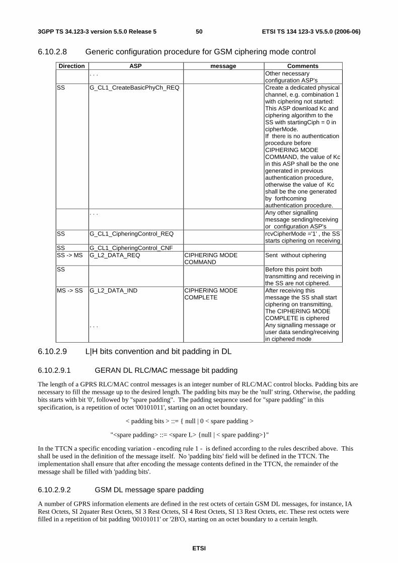
ETSI
ETSI TS 134 123-3 V5.5.0 (2006-06) 503GPP TS 34.123-3 version 5.5.0 Release 5
6.10.2.8 Generic configuration procedure for GSM ciphering mode control
Direction ASP message Comments . . . Other necessary
configuration ASP's SS G_CL1_CreateBasicPhyCh_REQ Create a dedicated physical
channel, e.g. combination 1 with ciphering not started: This ASP download Kc and ciphering algorithm to the SS with startingCiph = 0 in cipherMode. If there is no authentication procedure before CIPHERING MODE COMMAND, the value of Kc in this ASP shall be the one generated in previous authentication procedure, otherwise the value of Kc shall be the one generated by forthcoming authentication procedure.
. . . Any other signalling message sending/receiving or configuration ASP's
SS G_CL1_CipheringControl_REQ rcvCipherMode ='1' , the SS starts ciphering on receiving
SS G_CL1_CipheringControl_CNF SS -> MS G_L2_DATA_REQ CIPHERING MODE
COMMAND Sent without ciphering
SS Before this point both transmitting and receiving in the SS are not ciphered.
MS -> SS G_L2_DATA_IND CIPHERING MODE COMPLETE
After receiving this message the SS shall start ciphering on transmitting, The CIPHERING MODE COMPLETE is ciphered
. . . Any signalling message or user data sending/receiving in ciphered mode
6.10.2.9 L|H bits convention and bit padding in DL
6.10.2.9.1 GERAN DL RLC/MAC message bit padding
The length of a GPRS RLC/MAC control messages is an integer number of RLC/MAC control blocks. Padding bits are necessary to fill the message up to the desired length. The padding bits may be the 'null' string. Otherwise, the padding bits starts with bit '0', followed by "spare padding". The padding sequence used for "spare padding" in this specification, is a repetition of octet '00101011', starting on an octet boundary.
< padding bits > ::= { null | 0 < spare padding >
"<spare padding> ::= <spare L> {null | < spare padding>}"
In the TTCN a specific encoding variation - encoding rule 1 - is defined according to the rules described above. This shall be used in the definition of the message itself. No 'padding bits' field will be defined in the TTCN. The implementation shall ensure that after encoding the message contents defined in the TTCN, the remainder of the message shall be filled with 'padding bits'.
6.10.2.9.2 GSM DL message spare padding
A number of GPRS information elements are defined in the rest octets of certain GSM DL messages, for instance, IA Rest Octets, SI 2quater Rest Octets, SI 3 Rest Octets, SI 4 Rest Octets, SI 13 Rest Octets, etc. These rest octets were filled in a repetition of bit padding '00101011' or '2B'O, starting on an octet boundary to a certain length.
ETSI
ETSI TS 134 123-3 V5.5.0 (2006-06) 513GPP TS 34.123-3 version 5.5.0 Release 5
In the TTCN, a second encoding variation - encoding rule 2 - shall be used in the definition of the message itself, which shall be of a fixed length (always 23 octets). No "spare padding" field will be defined in the TTCN. The implementation shall ensure that after encoding the message contents defined in the TTCN, the remainder of the message, up to the defined fixed length, shall be filled with "spare padding".
6.10.2.9.3 L | H convention in rest octets of GSM DL messages
A number of GPRS information elements are defined in the rest octets of certain GSM DL messages. The special notations "L" and "H" are used to denote respectively the bit's logical value corresponding to the padding spare bit for that position, and the other value. The actual value of the bit transmitted by SS therefore depends upon its position within the octet - this involves counting bits.
In the TTCN a third encoding variation - encoding rule 3 - is defined for this purpose. This encoding variation is applied to those specific TTCN Rest Octets definitions which contain the L|H convention.
6.10.2.9.4 Spare Bits
Where the IE definition of RLC/MAC blocks contains bits defined to be 'spare bits', these bits shall set to the value '0' by the TTCN writers, according to the defined length indicator.
6.10.2.9.5 GSM System Information messages on SACCH
Certain GSM System Information messages, for instance, SI 5 and SI 6 are sent as a B4 frame on the SACCH. These messages are defined in 3GPP 44.006 [42], clause 8.8.3, to have a maximum of 19 octets.
In the TTCN a fourth encoding variation - encoding rule 4 - shall be used in the definition of the message itself. The implementation shall ensure that after encoding the message contents defined in the TTCN, the remainder of the message, up to the fixed length of 19 octets, shall be filled with "spare padding".
6.10.2.9.6 GSM Measurement Information messages on SACCH
The GSM Measurement Information message is sent as a Bter UI frame on the SACCH. This messages is defined in 3GPP 44.006 [42], clause 8.8.3 to have a maximum of 21 octets.
In the TTCN a fifth encoding variation - encoding rule 5 - shall be used in the definition of the message itself. The implementation shall ensure that after encoding the message contents defined in the TTCN, the remainder of the message, up to the fixed length of 21 octets, shall be filled with "spare padding".
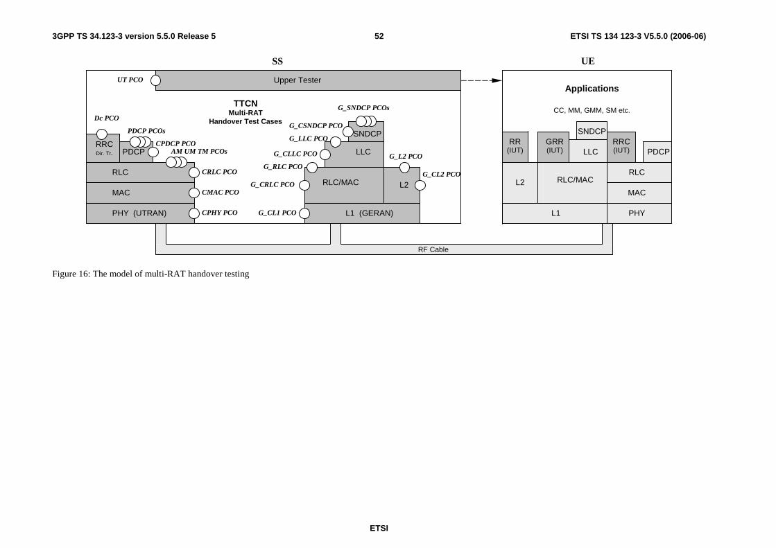
ETSI
ETSI TS 134 123-3 V5.5.0 (2006-06) 523GPP TS 34.123-3 version 5.5.0 Release 5
L1 (GERAN) PHY (UTRAN)
MAC
RLC
AM UM TM PCOs
CRLC PCO
CMAC PCO
CPHY PCO
RLC/MAC RLC/MAC
LLC
SNDCP
MAC
RLC
L1 PHY G_CL1 PCO
G_RLC PCO
TTCN Multi-RAT
Handover Test Cases
SS UE
RF Cable
RRC (IUT) PDCP LLC
SNDCP
Upper Tester
GRR (IUT)
L2
RR (IUT)
L2
G_L2 PCO
UT PCO
PDCP CPDCP PCO
G_CLLC PCO
G_CSNDCP PCO PDCP PCOs
G_SNDCP PCOs
Applications
G_CRLC PCO
RRC Dir. Tr.
Dc PCO CC, MM, GMM, SM etc.
G_LLC PCO
G_CL2 PCO
Figure 16: The model of multi-RAT handover testing

ETSI
ETSI TS 134 123-3 V5.5.0 (2006-06) 533GPP TS 34.123-3 version 5.5.0 Release 5
6.11 DCH-DSCH model (R99 or Rel-4) The model illustrates the relationship between various channels from logical channel to physical channels. DCH are associated with DSCH.
DSCH
DSCH model
DCH associated with DSCH
Coded Composite Transport Channel
(CCTrCH)
Physical Channel Data Streams
MUX
DCH
Encoding and
multiplexing
Cell 1 Phy CH Phy CH
DCH DCH
DCH model
TPC stream 1, TFCI2
TFCI1 indicates the DCH specific TFC and TFCI2 indicates the DSCH specific TFC and also the PDSCH channelisation code(s)
Encoding and
multiplexing
DSCH
Coded Composite Transport Channel
(CCTrCH)
Physical Channel Data Streams
MUX
Phy CH Phy CH Cell 1 TPC stream 1, TFCI1
DCCH's DTCH's
MAC d
DTCH's
MAC c/sh
Figure 17: Associated DCH-DSCH model
The model associating DCH with DSCH enable in the SS:
- to define DSCH transport channel;
- to define TFCI(field2) for DSCH;
- to configure PDSCH;
- to define DSCH-RNTI value.

ETSI
ETSI TS 134 123-3 V5.5.0 (2006-06) 543GPP TS 34.123-3 version 5.5.0 Release 5
6.12 DCH with HS-DSCH model (FDD, Rel-5 or later) The test model illustrates the relationship between various channels from logical channels to physical channels. All DCH are associated with a single HS-DSCH.
HS-DSCH
HS-DSCH model
DCH associated with HS-DSCH
Coded Composite Transport Channel
(CCTrCH)
Physical Channel Data Streams
PhyCh mapping
DCH
Encoding and
multiplexing
Cell 1 Phy CH Phy CH
DCH DCH
DCH model
DPCH’s
Encoding and
multiplexing
Coded Composite Transport Channel
(CCTrCH)
Physical Channel Data Streams
PhyCh mapping
Phy CH Phy CH
Cell 1
DCCH's DTCH's
MAC d
MAC-d flow
MAC hs
Cell 2 Phy CH Phy CH DPCH’s
HS-PDSCH’s
DTCH's
HS-DPCCH HS-SCCH’s
C/T MUX
Decoding
PhyCh mapping
Encoding
C/T MUX
MAC-d flow
Figure 18: Associated DCH with HS-DSCH model
Associating DCH with HS-DSCH, the model enables in the SS:
- to define MAC-hs and multiplexing of logical channels DTCHs onto MAC-d flows;
- to configure HS-DSCH transport channel and MAC-d flows;
- to configure HS-PDSCHs and HS-SCCHs;
- to define the H-RNTI value.
ETSI
ETSI TS 134 123-3 V5.5.0 (2006-06) 553GPP TS 34.123-3 version 5.5.0 Release 5
6.12a DCH with HS-DSCH model for 1.28 Mcps TDD (Rel-5 or later)
HS-DSCH
HS-DSCH model
DCH associated with HS-DSCH
Coded Composite Transport Channel
(CCTrCH)
Physical Channel Data Streams
PhyCh mapping
DCH
Encoding and
multiplexing
Cell 1 Phy CH Phy CH
DCH DCH
DCH model
DPCH’s
Encoding and
multiplexing
Coded Composite Transport Channel
(CCTrCH)
Physical Channel Data Streams
PhyCh mapping
Phy CH Phy CH
DCCH's DTCH's
MAC d
MAC-d flow
MAC hs
HS-PDSCH’s
DTCH's
HS-SICH HS-SCCH’s
C/T MUX
Decoding
PhyCh mapping
Encoding
C/T MUX
MAC-d flow
Figure 19: Associated DCH with HS-DSCH model for 1.28Mcps TDD
Associating DCH with HS-DSCH, the model enables in the SS:
to define MAC-hs and multiplexing of logical channels DTCHs onto MAC-d flows;
to configure HS-DSCH transport channel and MAC-d flows;
to configure HS-PDSCHs and HS-SCCHs;
to define the H-RNTI value.
6.13 E-DCH model (Rel-6 or later) The E-DCH model illustrates the relationship between various channels from logical channel to physical channels. In this model the TTCN writer can:
define MAC-e/es and multiplexing of logical channels onto MAC-d flows;
configure E-DCH transport channel and MAC-d flows;
configure E-DPDCH, E-DPCCH, E-HICH, E-RGCH and E-AGCH.
MAC-es and the served RLC are cell-independent and are configured by using the cell-id = -1. During reconfigurations, cell changes and state transitions, the relevant counters in the RLC are maintained.
For the reason of simplicity, the E-DCH testing model does not shown the relation between E-DCH and related DCH and HS-DPCH, however the TTCN writer shall understand that the E-DCH active set is a subset of the DCH active set, when configuring E-DCH in the SS the TTCN writer shall keep this requirement respected.
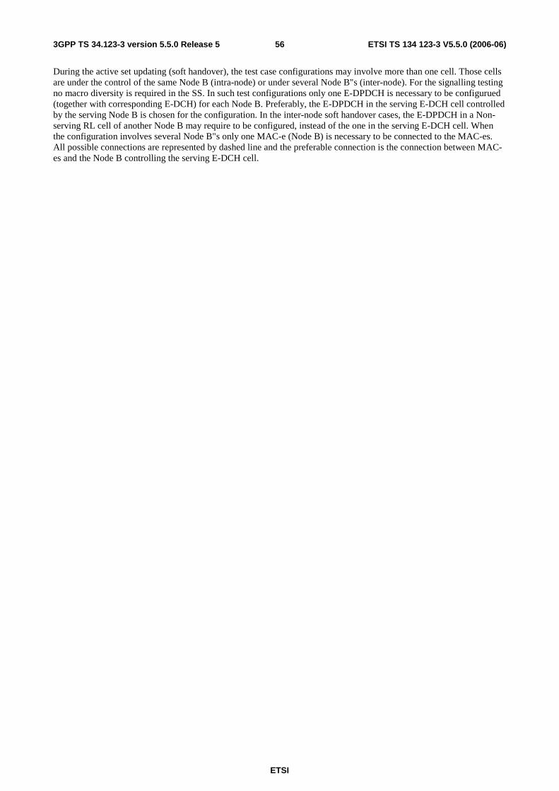
ETSI
ETSI TS 134 123-3 V5.5.0 (2006-06) 563GPP TS 34.123-3 version 5.5.0 Release 5
During the active set updating (soft handover), the test case configurations may involve more than one cell. Those cells are under the control of the same Node B (intra-node) or under several Node B"s (inter-node). For the signalling testing no macro diversity is required in the SS. In such test configurations only one E-DPDCH is necessary to be configurued (together with corresponding E-DCH) for each Node B. Preferably, the E-DPDCH in the serving E-DCH cell controlled by the serving Node B is chosen for the configuration. In the inter-node soft handover cases, the E-DPDCH in a Non-serving RL cell of another Node B may require to be configured, instead of the one in the serving E-DCH cell. When the configuration involves several Node B"s only one MAC-e (Node B) is necessary to be connected to the MAC-es. All possible connections are represented by dashed line and the preferable connection is the connection between MAC-es and the Node B controlling the serving E-DCH cell.

ETSI
ETSI TS 134 123-3 V5.5.0 (2006-06) 573GPP TS 34.123-3 version 5.5.0 Release 5
Connection between MAC_e and MAC_es is configured by connectedToMac_es in CMAC_MAC_e_Config_REQ
Configured by the same way as nonE-DCH case
d isassembly
H AR Q
ReorderingQ ueue d istribution
RLC RLC RLC
RB RB RB
process process
E -D PD C H ’s E-D PC C HE-H IC H
E-D C H
Logical C H ’s
MAC_e
Configured by CMAC_MACes_Config_REQ, (MAC-dFlow mapped to logicalCH)
Configured by CMAC_MACe_Config_REQ, (MAC_e PDU mapped to MAC-dFlow)
Configured by: CMAC_MACe_AG_REQ, CMAC_MACe_RG_REQ
disassembly d isassembly
Reordering Reordering Reordering
ReorderingQ ueue d istribution
M AC_es
demultiplexing
Node B
E -H IC HE-R G C H E-AG C H E-R G C H
Schedule r
Serving E -DCH cell Serving RL cell
Node B
MAC_e
Non-serving RL cell Non-serving RL cell
E -D PD C H ’s E-D PC C H
E-H IC H
E-D C H
E-R G C H
demultiplexing
Schedule rH AR Q process
E-H IC H E-R G C H
Configured by CPHY_RL_Setup (consistent to UE config)
Figure 20: The model of E-DCH testing
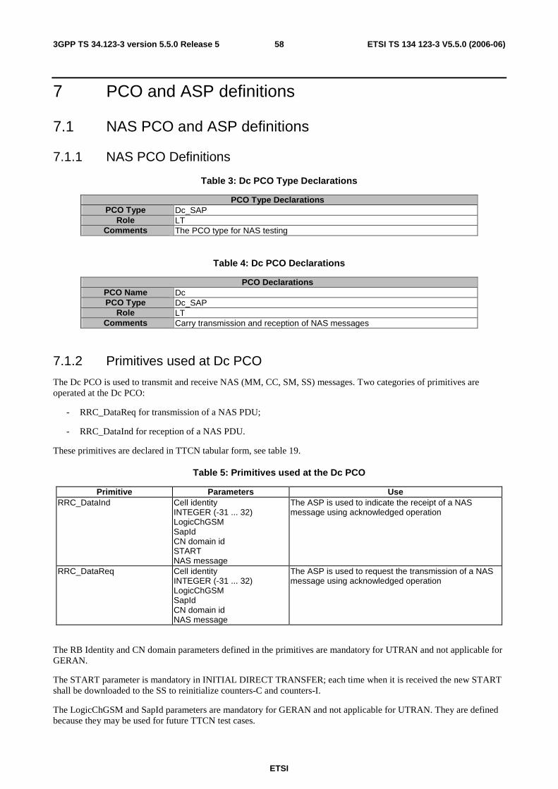
ETSI
ETSI TS 134 123-3 V5.5.0 (2006-06) 583GPP TS 34.123-3 version 5.5.0 Release 5
7 PCO and ASP definitions
7.1 NAS PCO and ASP definitions
7.1.1 NAS PCO Definitions
Table 3: Dc PCO Type Declarations
PCO Type Declarations PCO Type Dc_SAP
Role LT Comments The PCO type for NAS testing
Table 4: Dc PCO Declarations
PCO Declarations PCO Name Dc PCO Type Dc_SAP
Role LT Comments Carry transmission and reception of NAS messages
7.1.2 Primitives used at Dc PCO
The Dc PCO is used to transmit and receive NAS (MM, CC, SM, SS) messages. Two categories of primitives are operated at the Dc PCO:
- RRC_DataReq for transmission of a NAS PDU;
- RRC_DataInd for reception of a NAS PDU.
These primitives are declared in TTCN tabular form, see table 19.
Table 5: Primitives used at the Dc PCO
Primitive Parameters Use RRC_DataInd
Cell identity INTEGER (-31 ... 32) LogicChGSM SapId CN domain id START NAS message
The ASP is used to indicate the receipt of a NAS message using acknowledged operation
RRC_DataReq
Cell identity INTEGER (-31 ... 32) LogicChGSM SapId CN domain id NAS message
The ASP is used to request the transmission of a NAS message using acknowledged operation
The RB Identity and CN domain parameters defined in the primitives are mandatory for UTRAN and not applicable for GERAN.
The START parameter is mandatory in INITIAL DIRECT TRANSFER; each time when it is received the new START shall be downloaded to the SS to reinitialize counters-C and counters-I.
The LogicChGSM and SapId parameters are mandatory for GERAN and not applicable for UTRAN. They are defined because they may be used for future TTCN test cases.

ETSI
ETSI TS 134 123-3 V5.5.0 (2006-06) 593GPP TS 34.123-3 version 5.5.0 Release 5
Except the initial, uplink and downlink direct transfer procedures, the NAS TTCN specification uses the TTCN test steps to realize all RRC functions for testing. The single layer test concept is kept for the NAS tests.
A simple RRC emulation shall be maintained for the NAS tests. It has four functions:
- Emulate the three direct transfer procedures;
- Convert the NAS downlink messages defined in 3GPP TS 24.008 [9] in table format to the NAS message in ASN.1 octet string specified in 3GPP TS 25.331 [21]. Convert the NAS uplink message in the reverse way;
- PER encoding and decoding;
- Have the integrity protection.
RB3 and RB4 are specifically used for the NAS signalling. When an uplink message entered the receiving buffer at AM-SAP from the RLC emulation, either an RRC test step if running will take it out; or the RRC emulation if running will pick the received message from the buffer. Activation of any RRC test steps and activation of any NAS test steps at the same time shall be excluded in TTCN (no concurrency between them).
7.2 Ut PCO and ASP definitions
7.2.1 Ut PCO Declarations
The Ut PCO is served as the interface to the UE EMMI for remote control of operations, which have to be performed during execution of a test case such as to switch the UE on/off, initiate a call, etc.
Table 6: Declaration of the uppertester PCO type
PCO Type Declarations PCO Type MMI
Role UT Comments The PCO type for MMI or EMMI of the upper tester
Table 7: Declaration of the Ut PCO
PCO Declarations PCO Name Ut PCO Type MMI
Role UT Comments Carry transmission commands and reception of results for the upper tester
7.2.2 Primitives used at Ut PCO
The Ut PCO is used to indicate to the upper tester actions and to receive the acknowledgement of these actions. The AT commands are used wherever the suitable commands exist within 3GPP TS 27.007 [23], 3GPP TS 27.005 [22] and 3GPP TS 27 060 [24]. An MMI command is used, when AT commands does not exit for the action to performed. The primitives used at the Ut PCO, are declared in TTCN tabular form, see the table 19.
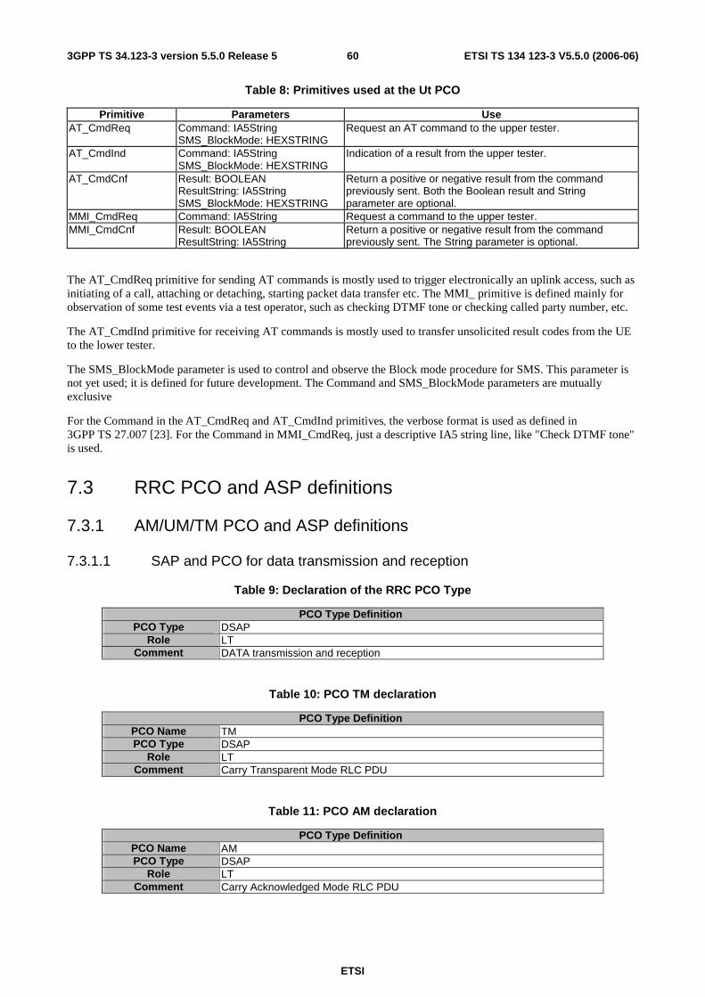
ETSI
ETSI TS 134 123-3 V5.5.0 (2006-06) 603GPP TS 34.123-3 version 5.5.0 Release 5
Table 8: Primitives used at the Ut PCO
Primitive Parameters Use AT_CmdReq Command: IA5String
SMS_BlockMode: HEXSTRING Request an AT command to the upper tester.
AT_CmdInd Command: IA5String SMS_BlockMode: HEXSTRING
Indication of a result from the upper tester.
AT_CmdCnf Result: BOOLEAN ResultString: IA5String SMS_BlockMode: HEXSTRING
Return a positive or negative result from the command previously sent. Both the Boolean result and String parameter are optional.
MMI_CmdReq Command: IA5String Request a command to the upper tester. MMI_CmdCnf Result: BOOLEAN
ResultString: IA5String Return a positive or negative result from the command previously sent. The String parameter is optional.
The AT_CmdReq primitive for sending AT commands is mostly used to trigger electronically an uplink access, such as initiating of a call, attaching or detaching, starting packet data transfer etc. The MMI_ primitive is defined mainly for observation of some test events via a test operator, such as checking DTMF tone or checking called party number, etc.
The AT_CmdInd primitive for receiving AT commands is mostly used to transfer unsolicited result codes from the UE to the lower tester.
The SMS_BlockMode parameter is used to control and observe the Block mode procedure for SMS. This parameter is not yet used; it is defined for future development. The Command and SMS_BlockMode parameters are mutually exclusive
For the Command in the AT_CmdReq and AT_CmdInd primitives, the verbose format is used as defined in 3GPP TS 27.007 [23]. For the Command in MMI_CmdReq, just a descriptive IA5 string line, like "Check DTMF tone" is used.
7.3 RRC PCO and ASP definitions
7.3.1 AM/UM/TM PCO and ASP definitions
7.3.1.1 SAP and PCO for data transmission and reception
Table 9: Declaration of the RRC PCO Type
PCO Type Definition PCO Type DSAP
Role LT Comment DATA transmission and reception
Table 10: PCO TM declaration
PCO Type Definition PCO Name TM PCO Type DSAP
Role LT Comment Carry Transparent Mode RLC PDU
Table 11: PCO AM declaration
PCO Type Definition PCO Name AM PCO Type DSAP
Role LT Comment Carry Acknowledged Mode RLC PDU
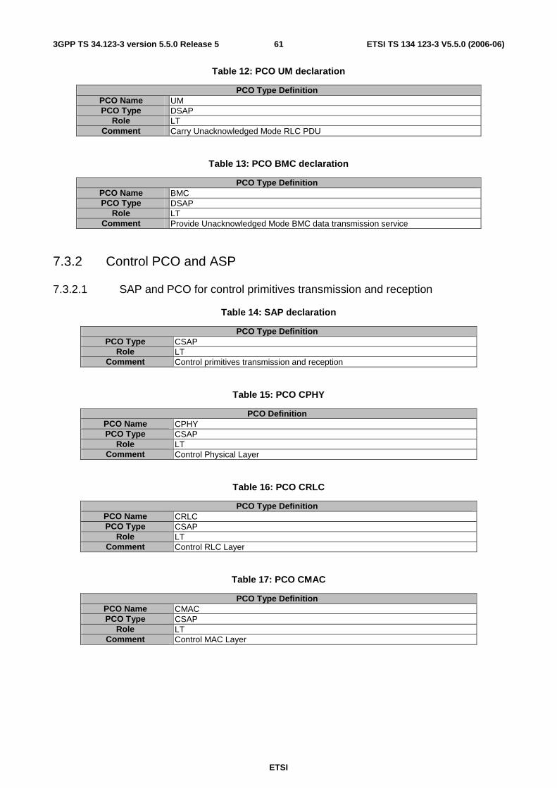
ETSI
ETSI TS 134 123-3 V5.5.0 (2006-06) 613GPP TS 34.123-3 version 5.5.0 Release 5
Table 12: PCO UM declaration
PCO Type Definition PCO Name UM PCO Type DSAP
Role LT Comment Carry Unacknowledged Mode RLC PDU
Table 13: PCO BMC declaration
PCO Type Definition PCO Name BMC PCO Type DSAP
Role LT Comment Provide Unacknowledged Mode BMC data transmission service
7.3.2 Control PCO and ASP
7.3.2.1 SAP and PCO for control primitives transmission and reception
Table 14: SAP declaration
PCO Type Definition PCO Type CSAP
Role LT Comment Control primitives transmission and reception
Table 15: PCO CPHY
PCO Definition PCO Name CPHY PCO Type CSAP
Role LT Comment Control Physical Layer
Table 16: PCO CRLC
PCO Type Definition PCO Name CRLC PCO Type CSAP
Role LT Comment Control RLC Layer
Table 17: PCO CMAC
PCO Type Definition PCO Name CMAC PCO Type CSAP
Role LT Comment Control MAC Layer

ETSI
ETSI TS 134 123-3 V5.5.0 (2006-06) 623GPP TS 34.123-3 version 5.5.0 Release 5
Table 18: PCO CBMC
PCO Type Definition PCO Name CBMC PCO Type CSAP
Role LT Comment Control BMC Layer
7.3.2.2 Control ASP Type Definition
7.3.2.2.1 CPHY_AICH_AckModeSet
ASN.1 ASP Type Definition Type Name CPHY_AICH_AckModeSet_REQ PCO Type CSAP Comment To request for setting of AICH Acknowledge Mode
Type Definition SEQUENCE { cellId INTEGER(0..63), routingInfo RoutingInfo, ratType RatType, aICH_Mode AICH_Mode }
ASN.1 ASP Type Definition Type Name CPHY_AICH_AckModeSet_CNF PCO Type CSAP Comment To confirm setting of AICH Acknowledge Mode
Type Definition SEQUENCE { cellId INTEGER(0..63), routingInfo RoutingInfo }
ASN.1 Type Definition Type Name AICH_Mode Comment Normal operation: The AICH will operate as normal, and will acknowledge or
negatively acknowledge on all UE RACH transmission attempts, appropriately. No Acknowledge: The AICH shall not transmit acknowledge or Negative Acknowledge on all UE RACH transmission attempts. Negative Acknowledge: The AICH shall transmit Negative Acknowledge on all UE RACH transmission attempts
Type Definition ENUMERATED { normal (0), noAck (1), negACK (2) }
7.3.2.2.2 CPHY_Cell_Config
ASN.1 ASP Type Definition Type Name CPHY_Cell_Config_CNF PCO Type CSAP Comment To confirm to setup the cell parameter
Type Definition SEQUENCE { cellId INTEGER(0..63) }

ETSI
ETSI TS 134 123-3 V5.5.0 (2006-06) 633GPP TS 34.123-3 version 5.5.0 Release 5
ASN.1 ASP Type Definition Type Name CPHY_Cell_Config_REQ PCO Type CSAP Comment To request to setup the cell parameter.
The unit of tcell is chip; the unit of sfnOffset is frame number; the primary scrambling code number of the cell is 16*primaryScramblingCode_SS; the unit of dLTxAttenuationLevel is dB.
Type Definition SEQUENCE { cellId INTEGER(0..63), tcell INTEGER(0..38399), sfnOffset INTEGER(0..4095), frequencyInfo FrequencyInfo, primaryScramblingCode_SS INTEGER(0..511), cellTxPowerLevel CellTxPowerLevel, dLTxAttenuationLevel INTEGER(0..30), frequencyBandIndicator FrequencyBandFDD }
ASN.1 Type Definition Type Name CellTxPowerLevel Comment The defaultCellTxPowerLvl is a default setting and is used for the most signalling
tests. The real total cell DL Tx power level equals to the sum of the DL Tx power of the individual physical channels configured. The totalCellTxPowerLvl applies to e.g. the idle mode tests in a non-default multi-cell radio environment.
Type Definition CHOICE { defaultCellTxPowerLvl NULL, totalCellTxPowerLvl DL_TxPower }
ASN.1 Type Definition Type Name FrequencyBandFDD Comment The frequency band indicator indicates how to interpret the radio frequency
broadcast.
Type Definition CHOICE { frequencyBandIndicator RadioFrequencyBandFDD, frequencyBandIndicator2 RadioFrequencyBandFDD2 }
7.3.2.2.3 CPHY_Cell_Release
ASN.1 ASP Type Definition Type Name CPHY_Cell_Release_CNF PCO Type CSAP Comment The confirmation to the CPHY_Cell_Release_Req
Type Definition SEQUENCE { soft_Reset BOOLEAN, cell_ID_List SEQUENCE (SIZE (1..8)) OF INTEGER(0..63) -- cell IDs }

ETSI
ETSI TS 134 123-3 V5.5.0 (2006-06) 643GPP TS 34.123-3 version 5.5.0 Release 5
ASN.1 ASP Type Definition Type Name CPHY_Cell_Release_REQ PCO Type CSAP Comment 1. This Primitive with "Soft_Reset" flag ON gives a common known starting
point/state of SS for a test case. The SS performs the following whenever it receives this primitive with "Soft_Reset" flag ON: Releases all configured Channels and cells (if any) irrespective of Cell ID list IE.
2. Releases the associated Memory Buffers (if any). 3. Cancels all active timers (if any)
With "Soft_Reset" flag OFF: 1. Releases cells listed in IE Cell_ID_List and associated configured
Channels (if any) 2. Releases the Memory Buffers(if any) associated with Cells listed in IE
Cell_ID_List 3. Cancels all active timers (if any) associated with Cells listed in IE
Cell_ID_List. Type Definition
SEQUENCE { soft_Reset BOOLEAN, cell_ID_List SEQUENCE (SIZE (1..8)) OF INTEGER(0..63) -- cell IDs }
7.3.2.2.3a CPHY_Cell_TimingAdjust
tbd
7.3.2.2.3b CPHY_Detect_TFCI
ASN.1 ASP Type Definition Type Name CPHY_DetectTFCI_CNF PCO Type CSAP Comment To confirm to CPHY_DetetTFCI_REQ
Type Definition SEQUENCE { cellId INTEGER(0..63) ), routingInfo RoutingInfo }
ASN.1 ASP Type Definition Type Name CPHY_DetectTFCI_REQ PCO Type CSAP Comment To set the mode of the SS for detecting whether the specified TFCI value
occurred. Usage: At the SS initialisation, the default mode is stop. When the mode is set to start, the SS shall detect whether the specified TFCI value (tfciValue) happens on the specified uplink physical channel, when happened the SS generates a CPHY_TFCI_Detected_IND and stop further detection. Otherwise keeps monitoring until a CPHY_DetectTFCI_REQ with mode = stop received.
Type Definition SEQUENCE { cellId INTEGER(0..63), routingInfo RoutingInfo, mode ENUMERATED{start(0), stop(1)}, tfciValue INTEGER (0..1023) }

ETSI
ETSI TS 134 123-3 V5.5.0 (2006-06) 653GPP TS 34.123-3 version 5.5.0 Release 5
ASN.1 ASP Type Definition Type Name CPHY_TFCI_Detected_IND PCO Type CSAP Comment To indicate the TFCI value specified in the CPHY_DetectTFCI_REQ has been
detected.
Type Definition SEQUENCE { cellId INTEGER(0..63), routingInfo RoutingInfo, tfciValue INTEGER (0..1023) }
7.3.2.2.4 CPHY_Ini
ASN.1 ASP Type Definition Type Name CPHY_Ini_REQ PCO Type CSAP Comment Request to initialize the test
Type Definition ENUMERATED { defaultRadioEnvironment(0), nonDefaultMultiCell(1) }
ASN.1 ASP Type Definition Type Name CPHY_Ini_CNF PCO Type CSAP Comment Confirm the test initialization
Type Definition SEQUENCE { confirmation NULL }
7.3.2.2.5 CPHY_Cell_TxPower_Modify
ASN.1 ASP Type Definition Type Name CPHY_Cell_TxPower_Modify_CNF PCO Type CSAP Comment To confirm to change the DL power
Type Definition SEQUENCE { cellId INTEGER(0..63) }
ASN.1 ASP Type Definition Type Name CPHY_Cell_TxPower_Modify_REQ PCO Type CSAP Comment To request to change the DL power
If the Tx attenuation level value is set to 123, the cell becomes a non-suitable off cell (CPICH_Ec ≤ -122 dBm/3.84 MHz of an off cell).
Type Definition SEQUENCE { cellId INTEGER(0..63), dLTxAttenuationLevel INTEGER(0..40|123) }
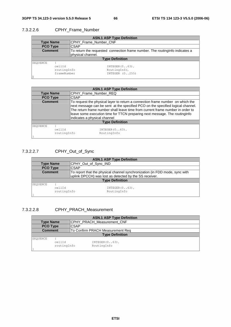
ETSI
ETSI TS 134 123-3 V5.5.0 (2006-06) 663GPP TS 34.123-3 version 5.5.0 Release 5
7.3.2.2.6 CPHY_Frame_Number
ASN.1 ASP Type Definition Type Name CPHY_Frame_Number_CNF PCO Type CSAP Comment To return the requested connection frame number. The routingInfo indicates a
physical channel. Type Definition
SEQUENCE { cellId INTEGER(0..63), routingInfo RoutingInfo, frameNumber INTEGER (0..255) }
ASN.1 ASP Type Definition Type Name CPHY_Frame_Number_REQ PCO Type CSAP Comment To request the physical layer to return a connection frame number on which the
next message can be sent at the specified PCO on the specified logical channel. The return frame number shall leave time from current frame number in order to leave some execution time for TTCN preparing next message. The routingInfo indicates a physical channel
Type Definition SEQUENCE { cellId INTEGER(0..63), routingInfo RoutingInfo }
7.3.2.2.7 CPHY_Out_of_Sync
ASN.1 ASP Type Definition Type Name CPHY_Out_of_Sync_IND PCO Type CSAP Comment To report that the physical channel synchronization (in FDD mode, sync with
uplink DPCCH) was lost as detected by the SS receiver. Type Definition
SEQUENCE { cellId INTEGER(0..63), routingInfo RoutingInfo }
7.3.2.2.8 CPHY_PRACH_Measurement
ASN.1 ASP Type Definition Type Name CPHY_PRACH_Measurement_CNF PCO Type CSAP Comment To Confirm PRACH Measurement Req
Type Definition SEQUENCE { cellId INTEGER(0..63), routingInfo RoutingInfo }

ETSI
ETSI TS 134 123-3 V5.5.0 (2006-06) 673GPP TS 34.123-3 version 5.5.0 Release 5
ASN.1 ASP Type Definition Type Name CPHY_PRACH_Measurement_REQ PCO Type CSAP Comment To request for Start or Stop of PRACH Measurements to be done every PRACH
PREAMBLE or MESSAGE received. Type Definition
SEQUENCE { cellId INTEGER(0..63), routingInfo RoutingInfo, ratType RatType, pRACH_MeasurementInd PRACH_MeasurementInd }
ASN.1 Type Definition Type Name PRACH_MeasurementInd Comment 1) StartMeas: The SS shall start the sending PRACH parameters
Measurement report on CPHY PCO, for each PRACH Preamble or MESSAGE received from the UE by primitive CPHY_PRACH_Measurement_Report_IND on CPHY PCO.
2) StopMeas: The SS shall stop sending of PRACH parameters Measurement report on CPHY PCO, for each PRACH Preamble or MESSAGE received from the UE by primitive CPHY_PRACH_Measurement_Report_IND on CPHY PCO.
Type Definition ENUMERATED { startMeas (0), stopMeas (1) }
ASN.1 ASP Type Definition Type Name CPHY_PRACH_Measurement_Report_IND PCO Type CSAP Comment SS indicates a PRACH parameters measurement report for each PRACH
Preambles or MESSAGE received from the UE Type Definition
SEQUENCE { cellId INTEGER(0..63), routingInfo RoutingInfo, ratType RatType, measurementReport PRACH_MeasurementReport }
ASN.1 Type Definition Type Name PRACH_MeasurementReport Comment
Type Definition SEQUENCE { usedPRACH_AcessSlot INTEGER (0..14), usedPRACH_Signature INTEGER (0..15) OPTIONAL }
7.3.2.2.9 CPHY_RL_Modify
ASN.1 ASP Type Definition Type Name CPHY_RL_Modify_CNF PCO Type CSAP Comment To confirm to modify the Radio Link
Type Definition SEQUENCE { cellId INTEGER(0..63), routingInfo RoutingInfo }
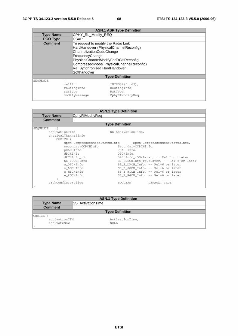
ETSI
ETSI TS 134 123-3 V5.5.0 (2006-06) 683GPP TS 34.123-3 version 5.5.0 Release 5
ASN.1 ASP Type Definition Type Name CPHY_RL_Modify_REQ PCO Type CSAP Comment To request to modify the Radio Link
HardHandover (PhysicalChannelReconfig) ChannelizationCodeChange FrequencyChange PhysicalChannelModifyForTrCHReconfig CompressedMode( PhysicalChannelReconfig) Re_Synchronized HardHandover Softhandover
Type Definition SEQUENCE { cellId INTEGER(0..63), routingInfo RoutingInfo, ratType RatType, modifyMessage CphyRlModifyReq }
ASN.1 Type Definition Type Name CphyRlModifyReq Comment
Type Definition SEQUENCE { activationTime SS_ActivationTime, physicalChannelInfo CHOICE { dpch_CompressedModeStatusInfo Dpch_CompressedModeStatusInfo, secondaryCCPCHInfo SecondaryCCPCHInfo, pRACHInfo PRACHInfo, dPCHInfo DPCHInfo, dPCHInfo_r5 DPCHInfo_r5OrLater, -- Rel-5 or later hS_PDSCHInfo HS_PDSCHInfo_r5OrLater, -- Rel-5 or later e_DPCHInfo SS_E_DPCH_Info, -- Rel-6 or later e_AGCHInfo SS_E_AGCH_Info, -- Rel-6 or later e_HICHInfo SS_E_HICH_Info, -- Rel-6 or later e_RGCHInfo SS_E_RGCH_Info -- Rel-6 or later }, trchConfigToFollow BOOLEAN DEFAULT TRUE }
ASN.1 Type Definition Type Name SS_ActivationTime Comment
Type Definition CHOICE { activationCFN ActivationTime, activateNow NULL }
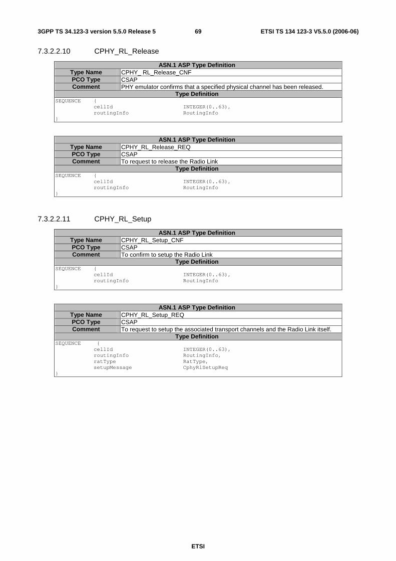
ETSI
ETSI TS 134 123-3 V5.5.0 (2006-06) 693GPP TS 34.123-3 version 5.5.0 Release 5
7.3.2.2.10 CPHY_RL_Release
ASN.1 ASP Type Definition Type Name CPHY_ RL_Release_CNF PCO Type CSAP Comment PHY emulator confirms that a specified physical channel has been released.
Type Definition SEQUENCE { cellId INTEGER(0..63), routingInfo RoutingInfo }
ASN.1 ASP Type Definition Type Name CPHY_RL_Release_REQ PCO Type CSAP Comment To request to release the Radio Link
Type Definition SEQUENCE { cellId INTEGER(0..63), routingInfo RoutingInfo }
7.3.2.2.11 CPHY_RL_Setup
ASN.1 ASP Type Definition Type Name CPHY_RL_Setup_CNF PCO Type CSAP Comment To confirm to setup the Radio Link
Type Definition SEQUENCE { cellId INTEGER(0..63), routingInfo RoutingInfo }
ASN.1 ASP Type Definition Type Name CPHY_RL_Setup_REQ PCO Type CSAP Comment To request to setup the associated transport channels and the Radio Link itself.
Type Definition SEQUENCE { cellId INTEGER(0..63), routingInfo RoutingInfo, ratType RatType, setupMessage CphyRlSetupReq }
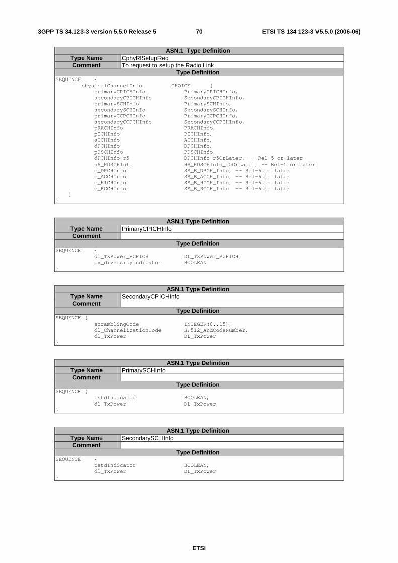
ETSI
ETSI TS 134 123-3 V5.5.0 (2006-06) 703GPP TS 34.123-3 version 5.5.0 Release 5
ASN.1 Type Definition Type Name CphyRlSetupReq Comment To request to setup the Radio Link
Type Definition SEQUENCE { physicalChannelInfo CHOICE { primaryCPICHInfo PrimaryCPICHInfo, secondaryCPICHInfo SecondaryCPICHInfo, primarySCHInfo PrimarySCHInfo, secondarySCHInfo SecondarySCHInfo, primaryCCPCHInfo PrimaryCCPCHInfo, secondaryCCPCHInfo SecondaryCCPCHInfo, pRACHInfo PRACHInfo, pICHInfo PICHInfo, aICHInfo AICHInfo, dPCHInfo DPCHInfo, pDSCHInfo PDSCHInfo, dPCHInfo_r5 DPCHInfo_r5OrLater, -- Rel-5 or later hS_PDSCHInfo HS_PDSCHInfo_r5OrLater, -- Rel-5 or later e_DPCHInfo SS_E_DPCH_Info, -- Rel-6 or later e_AGCHInfo SS_E_AGCH_Info, -- Rel-6 or later e_HICHInfo SS_E_HICH_Info, -- Rel-6 or later e_RGCHInfo SS_E_RGCH_Info -- Rel-6 or later } }
ASN.1 Type Definition Type Name PrimaryCPICHInfo Comment
Type Definition SEQUENCE { dl_TxPower_PCPICH DL_TxPower_PCPICH, tx_diversityIndicator BOOLEAN }
ASN.1 Type Definition Type Name SecondaryCPICHInfo Comment
Type Definition SEQUENCE { scramblingCode INTEGER(0..15), dl_ChannelizationCode SF512_AndCodeNumber, dl_TxPower DL_TxPower }
ASN.1 Type Definition Type Name PrimarySCHInfo Comment
Type Definition SEQUENCE { tstdIndicator BOOLEAN, dl_TxPower DL_TxPower }
ASN.1 Type Definition Type Name SecondarySCHInfo Comment
Type Definition SEQUENCE { tstdIndicator BOOLEAN, dl_TxPower DL_TxPower }
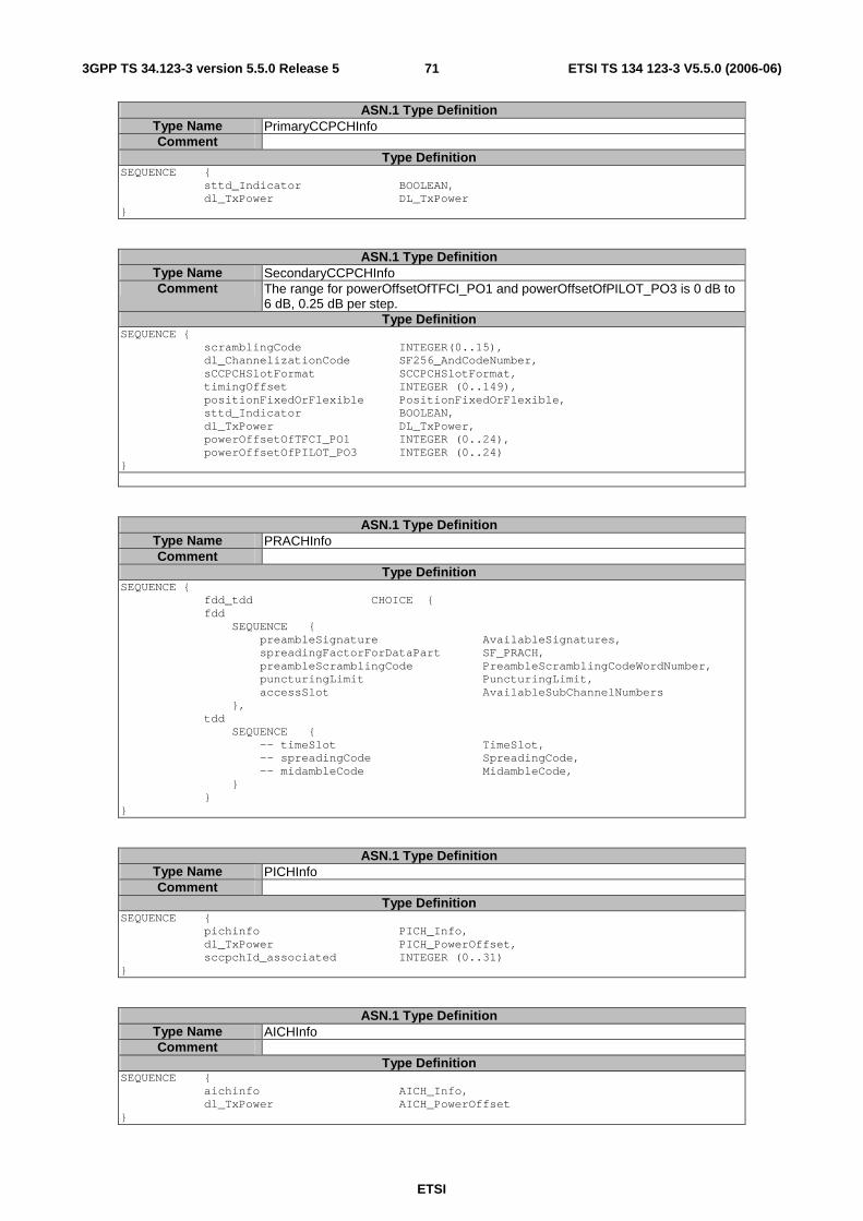
ETSI
ETSI TS 134 123-3 V5.5.0 (2006-06) 713GPP TS 34.123-3 version 5.5.0 Release 5
ASN.1 Type Definition Type Name PrimaryCCPCHInfo Comment
Type Definition SEQUENCE { sttd_Indicator BOOLEAN, dl_TxPower DL_TxPower }
ASN.1 Type Definition Type Name SecondaryCCPCHInfo Comment The range for powerOffsetOfTFCI_PO1 and powerOffsetOfPILOT_PO3 is 0 dB to
6 dB, 0.25 dB per step. Type Definition
SEQUENCE { scramblingCode INTEGER(0..15), dl_ChannelizationCode SF256_AndCodeNumber, sCCPCHSlotFormat SCCPCHSlotFormat, timingOffset INTEGER (0..149), positionFixedOrFlexible PositionFixedOrFlexible, sttd_Indicator BOOLEAN, dl_TxPower DL_TxPower, powerOffsetOfTFCI_PO1 INTEGER (0..24), powerOffsetOfPILOT_PO3 INTEGER (0..24) }
ASN.1 Type Definition Type Name PRACHInfo Comment
Type Definition SEQUENCE { fdd_tdd CHOICE { fdd SEQUENCE { preambleSignature AvailableSignatures, spreadingFactorForDataPart SF_PRACH, preambleScramblingCode PreambleScramblingCodeWordNumber, puncturingLimit PuncturingLimit, accessSlot AvailableSubChannelNumbers }, tdd SEQUENCE { -- timeSlot TimeSlot, -- spreadingCode SpreadingCode, -- midambleCode MidambleCode, } } }
ASN.1 Type Definition Type Name PICHInfo Comment
Type Definition SEQUENCE { pichinfo PICH_Info, dl_TxPower PICH_PowerOffset, sccpchId_associated INTEGER (0..31) }
ASN.1 Type Definition Type Name AICHInfo Comment
Type Definition SEQUENCE { aichinfo AICH_Info, dl_TxPower AICH_PowerOffset }
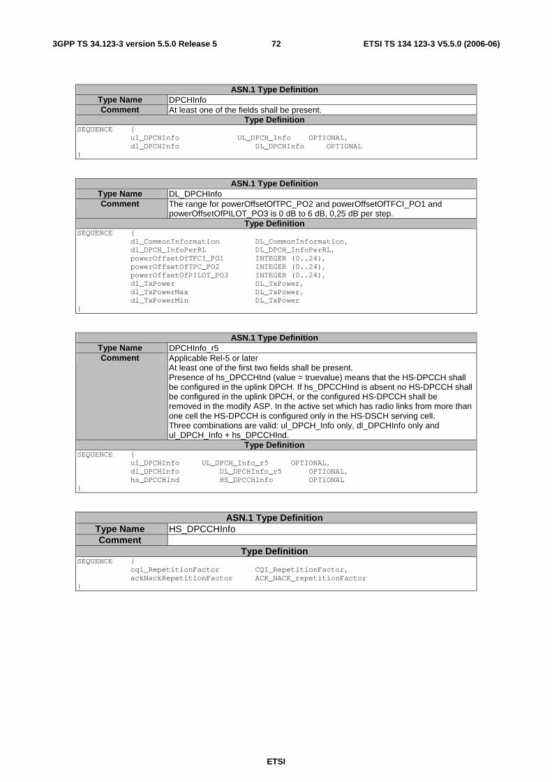
ETSI
ETSI TS 134 123-3 V5.5.0 (2006-06) 723GPP TS 34.123-3 version 5.5.0 Release 5
ASN.1 Type Definition Type Name DPCHInfo Comment At least one of the fields shall be present.
Type Definition SEQUENCE { ul_DPCHInfo UL_DPCH_Info OPTIONAL, dl_DPCHInfo DL_DPCHInfo OPTIONAL }
ASN.1 Type Definition Type Name DL_DPCHInfo Comment The range for powerOffsetOfTPC_PO2 and powerOffsetOfTFCI_PO1 and
powerOffsetOfPILOT_PO3 is 0 dB to 6 dB, 0,25 dB per step. Type Definition
SEQUENCE { dl_CommonInformation DL_CommonInformation, dl_DPCH_InfoPerRL DL_DPCH_InfoPerRL, powerOffsetOfTFCI_PO1 INTEGER (0..24), powerOffsetOfTPC_PO2 INTEGER (0..24), powerOffsetOfPILOT_PO3 INTEGER (0..24), dl_TxPower DL_TxPower, dl_TxPowerMax DL_TxPower, dl_TxPowerMin DL_TxPower }
ASN.1 Type Definition Type Name DPCHInfo_r5 Comment Applicable Rel-5 or later
At least one of the first two fields shall be present. Presence of hs_DPCCHInd (value = truevalue) means that the HS-DPCCH shall be configured in the uplink DPCH. If hs_DPCCHInd is absent no HS-DPCCH shall be configured in the uplink DPCH, or the configured HS-DPCCH shall be removed in the modify ASP. In the active set which has radio links from more than one cell the HS-DPCCH is configured only in the HS-DSCH serving cell. Three combinations are valid: ul_DPCH_Info only, dl_DPCHInfo only and ul_DPCH_Info + hs_DPCCHInd.
Type Definition SEQUENCE { ul_DPCHInfo UL_DPCH_Info_r5 OPTIONAL, dl_DPCHInfo DL_DPCHInfo_r5 OPTIONAL, hs_DPCCHInd HS_DPCCHInfo OPTIONAL }
ASN.1 Type Definition Type Name HS_DPCCHInfo Comment
Type Definition SEQUENCE { cqi_RepetitionFactor CQI_RepetitionFactor, ackNackRepetitionFactor ACK_NACK_repetitionFactor }

ETSI
ETSI TS 134 123-3 V5.5.0 (2006-06) 733GPP TS 34.123-3 version 5.5.0 Release 5
ASN.1 Type Definition Type Name DL_DPCHInfo_r5 Comment Applicable Rel-5 or later
Type Definition SEQUENCE { dl_CommonInformation DL_CommonInformation_r5, dl_DPCH_InfoPerRL DL_DPCH_InfoPerRL_r5, powerOffsetOfTFCI_PO1 INTEGER (0..24), powerOffsetOfTPC_PO2 INTEGER (0..24), powerOffsetOfPILOT_PO3 INTEGER (0..24), dl_TxPower DL_TxPower, dl_TxPowerMax DL_TxPower, dl_TxPowerMin DL_TxPower }
ASN.1 Type Definition Type Name HS_PDSCHInfo Comment Applicable Rel-5 or later
When CHY_RL_Setup_REQ is called with CHOICE of hS_PDSCHInfo HS_PDSCH and HS-SCCH shall be configured in SS. The following HS-DSCH related parameters are passed to the SS implicitly by HSDSCH_physical_layer_category: - Maximum number of HS-DSCH codes can be received by UE, - Minimum inter-TTI interval, - Maximum number of bits of an HS-DSCH transport block within an HS-DSCH TTI - Total number of soft channel bits". HSDSCH_physical_Layer_category is also used for interpretation of the meaning of CQI value.
Type Definition SEQUENCE { hSDSCHPhysicalLayerCategory HSDSCH_physical_layer_category, h_RNTI H_RNTI, dlHSPDSCHInformation DL_HSPDSCH_Information, sttd_Indicator BOOLEAN, hs_SCCH_TxPower DL_TxPower -- offset related to pilot bits -- on DL-DPCCH (25.433, 9.2.2.18I) }
ASN.1 Type Definition Type Name DL_TxPower_PCPICH Comment Absolute Tx Power of PCPICH
Type Definition INTEGER (-60..-30)
ASN.1 Type Definition Type Name DL_TxPower Comment Downlink Tx Power relative to PCPICH
Type Definition INTEGER (-35..+15)
ASN.1 Type Definition Type Name SCCPCHSlotFormat Comment Reference to 3GPP TS25.211 [Error! Reference source not found.]
Type Definition INTEGER (0..17)

ETSI
ETSI TS 134 123-3 V5.5.0 (2006-06) 743GPP TS 34.123-3 version 5.5.0 Release 5
ASN.1 Type Definition Type Name PDSCHInfo Comment
Type Definition SEQUENCE { fdd_tdd CHOICE { fdd SEQUENCE { pdsch_CodeMapping PDSCH_CodeMapping }, tdd SEQUENCE { --pdsch_Identity PDSCH_Identity, --pdsch_Info PDSCH_Info, --pdsch_PowerControlInfo PDSCH_PowerControlInfo OPTIONAL }, }, dl_TxPower DL_TxPower }
ASN.1 Type Definition Type Name DPCHInfo_r5OrLater Comment Applicable Rel-5 or later
At least one of the first two fields shall be present. Presence of hs_DPCCHInd (value = truevalue) means that the HS-DPCCH shall be configured in the uplink DPCH. If hs_DPCCHInd is absent no HS-DPCCH shall be configured in the uplink DPCH, or the configured HS-DPCCH shall be removed in the modify ASP. In the active set which has radio links from more than one cell the HS-DPCCH is configured only in the HS-DSCH serving cell. Three combinations are valid: ul_DPCH_Info only, dl_DPCHInfo only and ul_DPCH_Info + hs_DPCCHInd.
Type Definition CHOICE { r5 SEQUENCE { ul_DPCHInfo UL_DPCH_Info_r5 OPTIONAL, dl_DPCHInfo DL_DPCHInfo_r5 OPTIONAL, hs_DPCCHInd HS_DPCCHInfo OPTIONAL }, r6 SEQUENCE { ul_DPCHInfo6 UL_DPCH_Info_r6 OPTIONAL, dl_DPCHInfo6 DL_DPCHInfo_r6 OPTIONAL, hs_DPCCHInd HS_DPCCHInfo OPTIONAL }, spare1 SEQUENCE {}, spare2 SEQUENCE {} }
ASN.1 Type Definition Type Name DL_DPCHInfo_r6 Comment Applicable Rel-5 or later
Type Definition SEQUENCE { dl_CommonInformation DL_CommonInformation_r6, dl_Dpch_InfoPerRL CHOICE { dl_DPCH_InfoPerRL DL_DPCH_InfoPerRL_r6, dl_FDPCH_InfoPerRL DL_FDPCH_InfoPerRL_r6 }, powerOffsetOfTFCI_PO1 INTEGER (0..24), powerOffsetOfTPC_PO2 INTEGER (0..24), powerOffsetOfPILOT_PO3 INTEGER (0..24), dl_TxPower DL_TxPower, dl_TxPowerMax DL_TxPower, dl_TxPowerMin DL_TxPower }
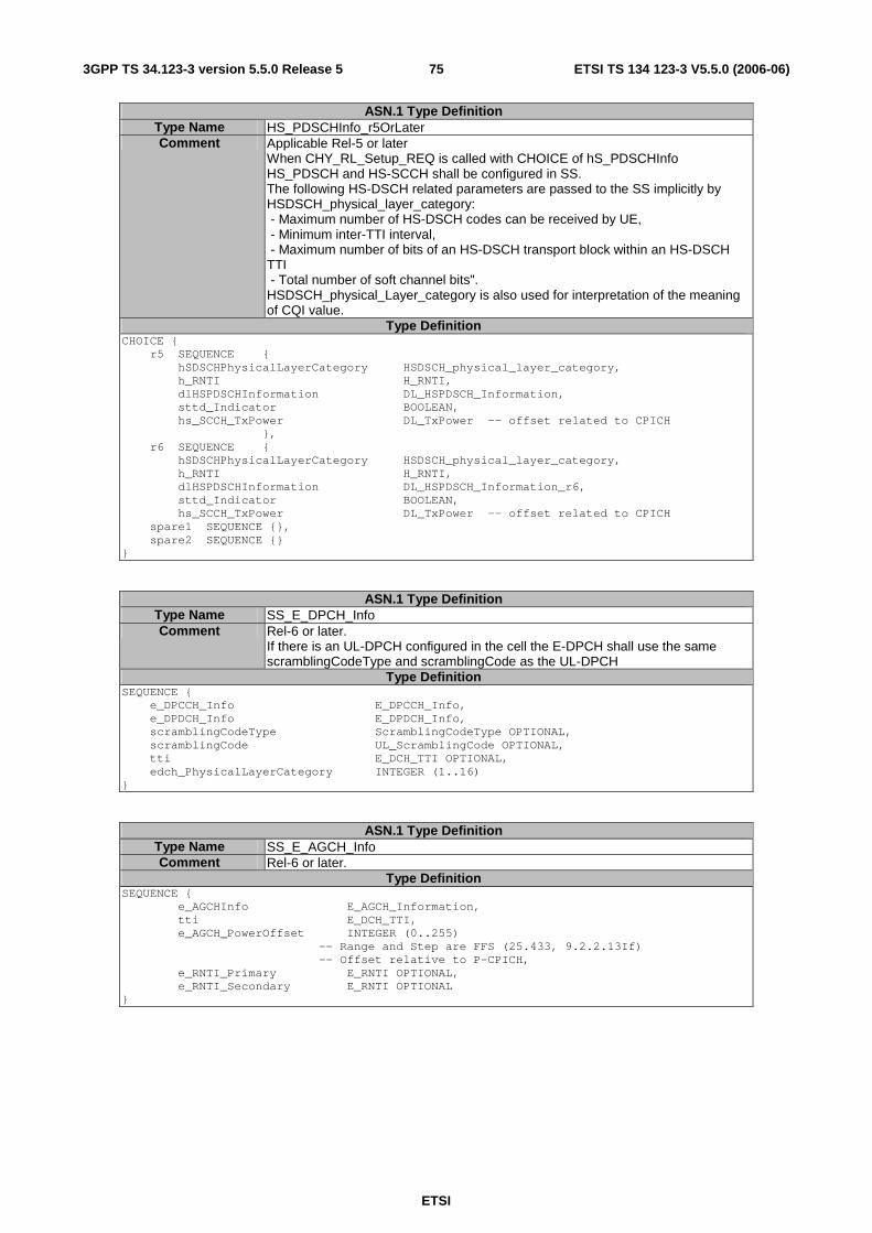
ETSI
ETSI TS 134 123-3 V5.5.0 (2006-06) 753GPP TS 34.123-3 version 5.5.0 Release 5
ASN.1 Type Definition Type Name HS_PDSCHInfo_r5OrLater Comment Applicable Rel-5 or later
When CHY_RL_Setup_REQ is called with CHOICE of hS_PDSCHInfo HS_PDSCH and HS-SCCH shall be configured in SS. The following HS-DSCH related parameters are passed to the SS implicitly by HSDSCH_physical_layer_category: - Maximum number of HS-DSCH codes can be received by UE, - Minimum inter-TTI interval, - Maximum number of bits of an HS-DSCH transport block within an HS-DSCH TTI - Total number of soft channel bits". HSDSCH_physical_Layer_category is also used for interpretation of the meaning of CQI value.
Type Definition CHOICE { r5 SEQUENCE { hSDSCHPhysicalLayerCategory HSDSCH_physical_layer_category, h_RNTI H_RNTI, dlHSPDSCHInformation DL_HSPDSCH_Information, sttd_Indicator BOOLEAN, hs_SCCH_TxPower DL_TxPower -- offset related to CPICH }, r6 SEQUENCE { hSDSCHPhysicalLayerCategory HSDSCH_physical_layer_category, h_RNTI H_RNTI, dlHSPDSCHInformation DL_HSPDSCH_Information_r6, sttd_Indicator BOOLEAN, hs_SCCH_TxPower DL_TxPower -- offset related to CPICH spare1 SEQUENCE {}, spare2 SEQUENCE {} }
ASN.1 Type Definition Type Name SS_E_DPCH_Info Comment Rel-6 or later.
If there is an UL-DPCH configured in the cell the E-DPCH shall use the same scramblingCodeType and scramblingCode as the UL-DPCH
Type Definition SEQUENCE { e_DPCCH_Info E_DPCCH_Info, e_DPDCH_Info E_DPDCH_Info, scramblingCodeType ScramblingCodeType OPTIONAL, scramblingCode UL_ScramblingCode OPTIONAL, tti E_DCH_TTI OPTIONAL, edch_PhysicalLayerCategory INTEGER (1..16) }
ASN.1 Type Definition Type Name SS_E_AGCH_Info Comment Rel-6 or later.
Type Definition SEQUENCE { e_AGCHInfo E_AGCH_Information, tti E_DCH_TTI, e_AGCH_PowerOffset INTEGER (0..255) -- Range and Step are FFS (25.433, 9.2.2.13If) -- Offset relative to P-CPICH, e_RNTI_Primary E_RNTI OPTIONAL, e_RNTI_Secondary E_RNTI OPTIONAL }
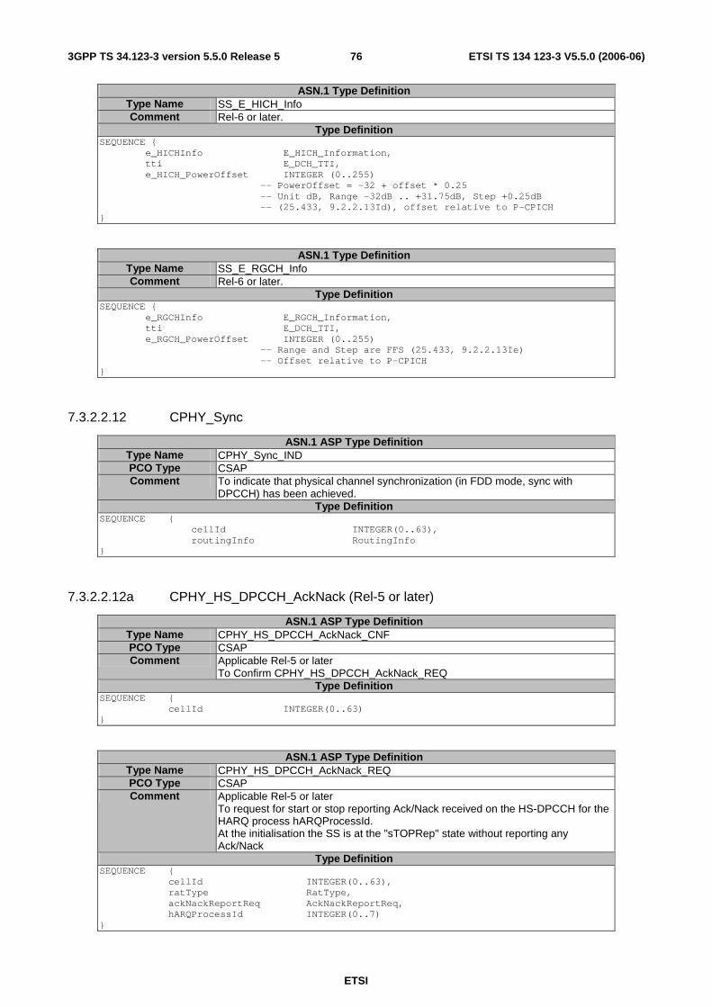
ETSI
ETSI TS 134 123-3 V5.5.0 (2006-06) 763GPP TS 34.123-3 version 5.5.0 Release 5
ASN.1 Type Definition Type Name SS_E_HICH_Info Comment Rel-6 or later.
Type Definition SEQUENCE { e_HICHInfo E_HICH_Information, tti E_DCH_TTI, e_HICH_PowerOffset INTEGER (0..255) -- PowerOffset = -32 + offset * 0.25 -- Unit dB, Range -32dB .. +31.75dB, Step +0.25dB -- (25.433, 9.2.2.13Id), offset relative to P-CPICH }
ASN.1 Type Definition Type Name SS_E_RGCH_Info Comment Rel-6 or later.
Type Definition SEQUENCE { e_RGCHInfo E_RGCH_Information, tti E_DCH_TTI, e_RGCH_PowerOffset INTEGER (0..255) -- Range and Step are FFS (25.433, 9.2.2.13Ie) -- Offset relative to P-CPICH }
7.3.2.2.12 CPHY_Sync
ASN.1 ASP Type Definition Type Name CPHY_Sync_IND PCO Type CSAP Comment To indicate that physical channel synchronization (in FDD mode, sync with
DPCCH) has been achieved. Type Definition
SEQUENCE { cellId INTEGER(0..63),
routingInfo RoutingInfo }
7.3.2.2.12a CPHY_HS_DPCCH_AckNack (Rel-5 or later)
ASN.1 ASP Type Definition Type Name CPHY_HS_DPCCH_AckNack_CNF PCO Type CSAP Comment Applicable Rel-5 or later
To Confirm CPHY_HS_DPCCH_AckNack_REQ Type Definition
SEQUENCE { cellId INTEGER(0..63) }
ASN.1 ASP Type Definition Type Name CPHY_HS_DPCCH_AckNack_REQ PCO Type CSAP Comment Applicable Rel-5 or later
To request for start or stop reporting Ack/Nack received on the HS-DPCCH for the HARQ process hARQProcessId. At the initialisation the SS is at the "sTOPRep" state without reporting any Ack/Nack
Type Definition SEQUENCE { cellId INTEGER(0..63), ratType RatType, ackNackReportReq AckNackReportReq, hARQProcessId INTEGER(0..7) }
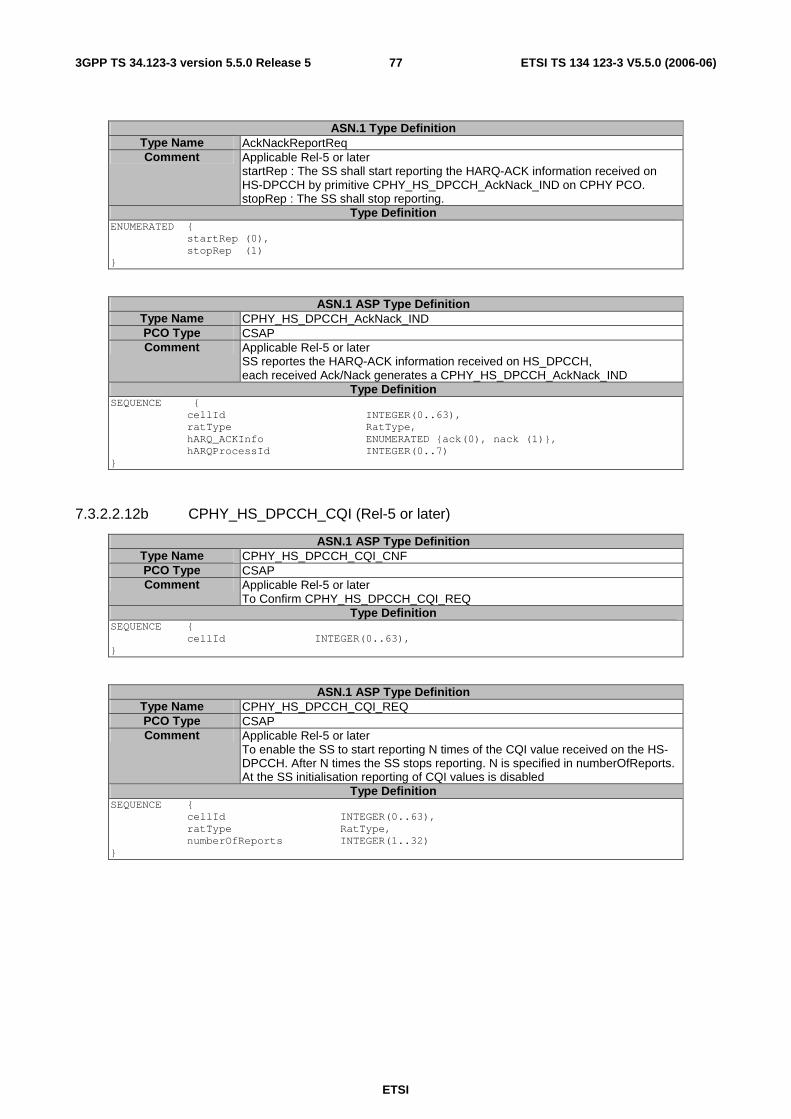
ETSI
ETSI TS 134 123-3 V5.5.0 (2006-06) 773GPP TS 34.123-3 version 5.5.0 Release 5
ASN.1 Type Definition Type Name AckNackReportReq Comment Applicable Rel-5 or later
startRep : The SS shall start reporting the HARQ-ACK information received on HS-DPCCH by primitive CPHY_HS_DPCCH_AckNack_IND on CPHY PCO. stopRep : The SS shall stop reporting.
Type Definition ENUMERATED { startRep (0), stopRep (1) }
ASN.1 ASP Type Definition Type Name CPHY_HS_DPCCH_AckNack_IND PCO Type CSAP Comment Applicable Rel-5 or later
SS reportes the HARQ-ACK information received on HS_DPCCH, each received Ack/Nack generates a CPHY_HS_DPCCH_AckNack_IND
Type Definition SEQUENCE { cellId INTEGER(0..63), ratType RatType, hARQ_ACKInfo ENUMERATED {ack(0), nack (1)}, hARQProcessId INTEGER(0..7) }
7.3.2.2.12b CPHY_HS_DPCCH_CQI (Rel-5 or later)
ASN.1 ASP Type Definition Type Name CPHY_HS_DPCCH_CQI_CNF PCO Type CSAP Comment Applicable Rel-5 or later
To Confirm CPHY_HS_DPCCH_CQI_REQ Type Definition
SEQUENCE { cellId INTEGER(0..63), }
ASN.1 ASP Type Definition Type Name CPHY_HS_DPCCH_CQI_REQ PCO Type CSAP Comment Applicable Rel-5 or later
To enable the SS to start reporting N times of the CQI value received on the HS-DPCCH. After N times the SS stops reporting. N is specified in numberOfReports. At the SS initialisation reporting of CQI values is disabled
Type Definition SEQUENCE { cellId INTEGER(0..63), ratType RatType, numberOfReports INTEGER(1..32) }

ETSI
ETSI TS 134 123-3 V5.5.0 (2006-06) 783GPP TS 34.123-3 version 5.5.0 Release 5
ASN.1 ASP Type Definition Type Name CPHY_HS_DPCCH_CQI_IND PCO Type CSAP Comment Applicable Rel-5 or later
SS generates the indication when a CQI value is received on HS_DPCCH after invocation of ASP CPHY_HS_DPCCH_CQI_REQ and before the numberOfReports is reached. This ASP is used for verifying whether the UE has configured the HS-DSCH and starts reception of HS-DSCH. (TS 25.331 cl.8.6.6.34)
Type Definition SEQUENCE { cellId INTEGER(0..63), ratType RatType, cqi INTEGER (0..30) }
7.3.2.2.12c CPHY_HS_DSCH_CRC_Mode (Rel-5 or later)
ASN.1 ASP Type Definition Type Name CPHY_HS_DSCH_CRC_Mode_CNF PCO Type CSAP Comment Applicable Rel-5 or later
Confirm a previous CPHY_HS_DSCH_CRC_Mode_REQ being successful. Type Definition
SEQUENCE { cellId INTEGER(-1..63), routingInfo RoutingInfo }
ASN.1 ASP Type Definition Type Name CPHY_HS_DSCH_CRC_Mode_REQ PCO Type CSAP Comment Applicable Rel-5 or later
To set the CRC calculation mode for HS-DSCH. If mode = normal, the SS generates the correct CRC. If mode = erroneous, the SS generates any wrong CRC value which is different from the correct one on the specified MACdFlow. As default, the normal mode is applied. When the HS-DSCH first configured or reconfigured the SS enters the normal CRC calculation mode.
Type Definition SEQUENCE { cellId INTEGER(-1..63) , routingInfo RoutingInfo, mac_dFlowId MAC_d_FlowIdentity, mode ENUMERATED {normal(0), erroneous(1)} }
7.3.2.2.13 CPHY_TrCH_Config
ASN.1 ASP Type Definition Type Name CPHY_TrCH_Config_CNF PCO Type CSAP Comment To confirm to configure the transport channel
Type Definition SEQUENCE { cellId INTEGER(0..63), routingInfo RoutingInfo }
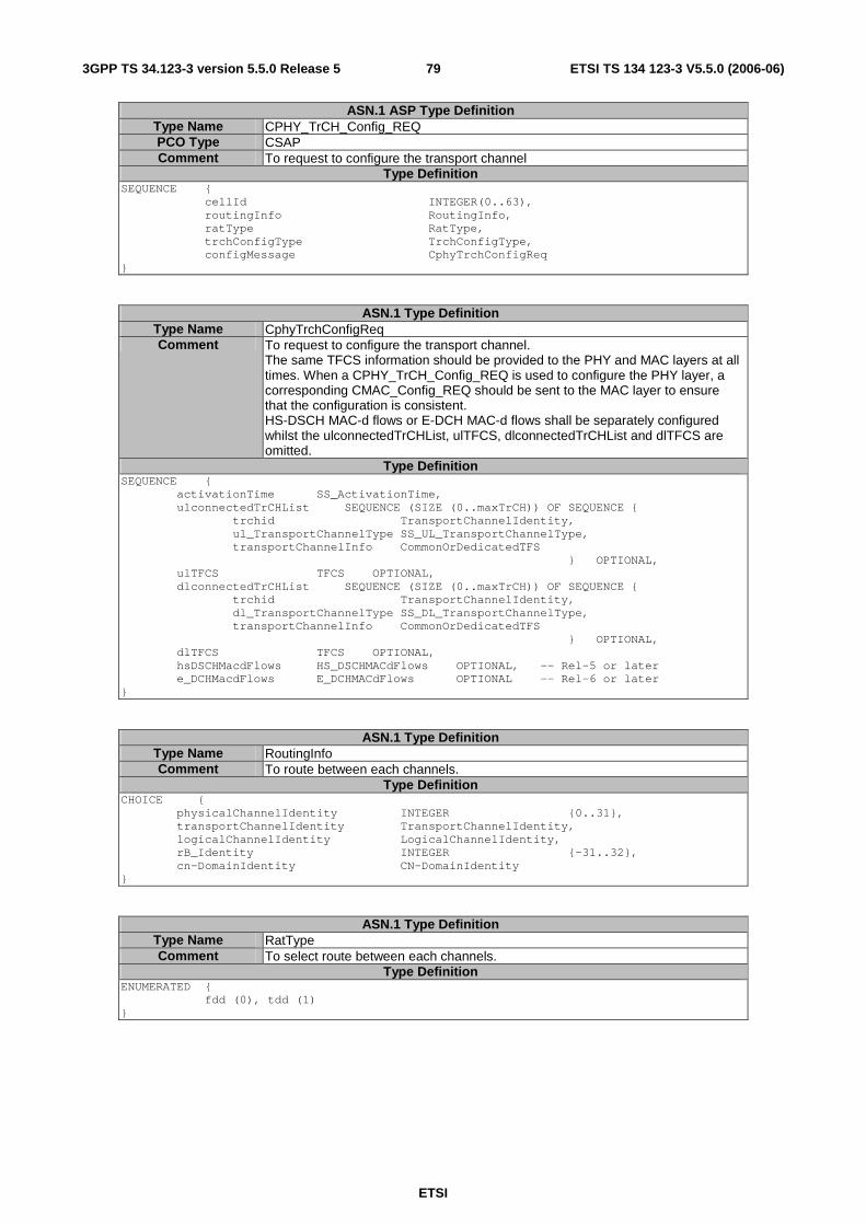
ETSI
ETSI TS 134 123-3 V5.5.0 (2006-06) 793GPP TS 34.123-3 version 5.5.0 Release 5
ASN.1 ASP Type Definition Type Name CPHY_TrCH_Config_REQ PCO Type CSAP Comment To request to configure the transport channel
Type Definition SEQUENCE { cellId INTEGER(0..63), routingInfo RoutingInfo, ratType RatType, trchConfigType TrchConfigType, configMessage CphyTrchConfigReq }
ASN.1 Type Definition Type Name CphyTrchConfigReq Comment To request to configure the transport channel.
The same TFCS information should be provided to the PHY and MAC layers at all times. When a CPHY_TrCH_Config_REQ is used to configure the PHY layer, a corresponding CMAC_Config_REQ should be sent to the MAC layer to ensure that the configuration is consistent. HS-DSCH MAC-d flows or E-DCH MAC-d flows shall be separately configured whilst the ulconnectedTrCHList, ulTFCS, dlconnectedTrCHList and dlTFCS are omitted.
Type Definition SEQUENCE { activationTime SS_ActivationTime, ulconnectedTrCHList SEQUENCE (SIZE (0..maxTrCH)) OF SEQUENCE { trchid TransportChannelIdentity, ul_TransportChannelType SS_UL_TransportChannelType, transportChannelInfo CommonOrDedicatedTFS } OPTIONAL, ulTFCS TFCS OPTIONAL, dlconnectedTrCHList SEQUENCE (SIZE (0..maxTrCH)) OF SEQUENCE { trchid TransportChannelIdentity, dl_TransportChannelType SS_DL_TransportChannelType, transportChannelInfo CommonOrDedicatedTFS } OPTIONAL, dlTFCS TFCS OPTIONAL, hsDSCHMacdFlows HS_DSCHMACdFlows OPTIONAL, -- Rel-5 or later e_DCHMacdFlows E_DCHMACdFlows OPTIONAL -- Rel-6 or later }
ASN.1 Type Definition Type Name RoutingInfo Comment To route between each channels.
Type Definition CHOICE { physicalChannelIdentity INTEGER {0..31}, transportChannelIdentity TransportChannelIdentity, logicalChannelIdentity LogicalChannelIdentity, rB_Identity INTEGER {-31..32}, cn-DomainIdentity CN-DomainIdentity }
ASN.1 Type Definition Type Name RatType Comment To select route between each channels.
Type Definition ENUMERATED { fdd (0), tdd (1) }
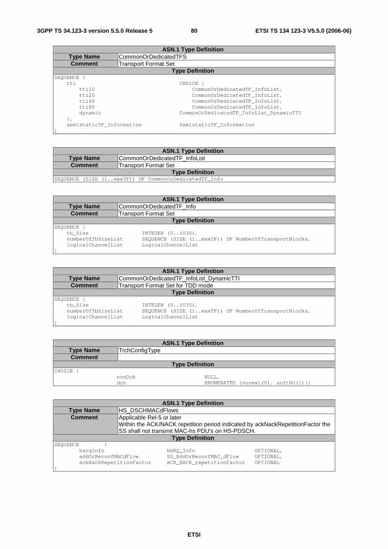
ETSI
ETSI TS 134 123-3 V5.5.0 (2006-06) 803GPP TS 34.123-3 version 5.5.0 Release 5
ASN.1 Type Definition Type Name CommonOrDedicatedTFS Comment Transport Format Set
Type Definition SEQUENCE { tti CHOICE { tti10 CommonOrDedicatedTF_InfoList, tti20 CommonOrDedicatedTF_InfoList, tti40 CommonOrDedicatedTF_InfoList, tti80 CommonOrDedicatedTF_InfoList, dynamic CommonOrDedicatedTF_InfoList_DynamicTTI }, semistaticTF_Information SemistaticTF_Information }
ASN.1 Type Definition Type Name CommonOrDedicatedTF_InfoList Comment Transport Format Set
Type Definition SEQUENCE (SIZE (1..maxTF)) OF CommonOrDedicatedTF_Info
ASN.1 Type Definition Type Name CommonOrDedicatedTF_Info Comment Transport Format Set
Type Definition SEQUENCE { tb_Size INTEGER (0..5035), numberOfTbSizeList SEQUENCE (SIZE (1..maxTF)) OF NumberOfTransportBlocks, logicalChannelList LogicalChannelList }
ASN.1 Type Definition Type Name CommonOrDedicatedTF_InfoList_DynamicTTI Comment Transport Format Set for TDD mode
Type Definition SEQUENCE { tb_Size INTEGER (0..5035), numberOfTbSizeList SEQUENCE (SIZE (1..maxTF)) OF NumberOfTransportBlocks, logicalChannelList LogicalChannelList }
ASN.1 Type Definition Type Name TrchConfigType Comment
Type Definition CHOICE { nonDch NULL, dch ENUMERATED {normal(0), softHO(1)}}
ASN.1 Type Definition Type Name HS_DSCHMACdFlows Comment Applicable Rel-5 or later
Within the ACK/NACK repetition period indicated by ackNackRepetitionFactor the SS shall not transmit MAC-hs PDU's on HS-PDSCH.
Type Definition SEQUENCE { harqInfo HARQ_Info OPTIONAL, addOrReconfMACdFlow SS_AddOrReconfMAC_dFlow OPTIONAL, ackNackRepetitionFactor ACK_NACK_repetitionFactor OPTIONAL }
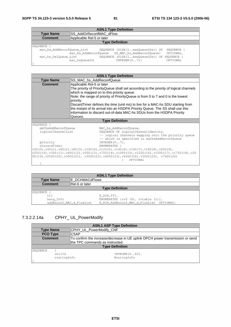
ETSI
ETSI TS 134 123-3 V5.5.0 (2006-06) 813GPP TS 34.123-3 version 5.5.0 Release 5
ASN.1 Type Definition Type Name SS_AddOrReconfMAC_dFlow Comment Applicable Rel-5 or later
Type Definition SEQUENCE { mac_hs_AddReconfQueue_List SEQUENCE (SIZE(1..maxQueueIDs)) OF SEQUENCE { mac_hs_AddReconfQueue SS_MAC_hs_AddReconfQueue} OPTIONAL, mac_hs_DelQueue_List SEQUENCE (SIZE(1..maxQueueIDs)) OF SEQUENCE { mac_hsQueueId INTEGER(0..7)} OPTIONAL }
ASN.1 Type Definition Type Name SS_MAC_hs_AddReconfQueue Comment Applicable Rel-5 or later
The priority of PriorityQueue shall set acoording to the priority of logical channels which is mapped on to this priority queue. Note: the range of priority of PriorityQueue is from 0 to 7 and 0 is the lowest priority. DiscardTimer defines the time (unit ms) to live for a MAC-hs SDU starting from the instant of its arrival into an HSDPA Priority Queue. The SS shall use this information to discard out-of-data MAC-hs SDUs from the HSDPA Priority Queues.
Type Definition SEQUENCE { mAChsAddReconfQueue MAC_hs_AddReconfQueue, logicalChannelList SEQUENCE OF LogicalChannelIdentity,
-- logical channels mapping onto the priority queue -- which is specified in maChsAddReconfQueue
priority INTEGER(0..7), discardTimer ENUMERATED { v20(0),v40(1),v60(2),v80(3),v100(4),v120(5),v140(6),v160(7),v180(8),v200(9), v250(10),v300(11),v400(12),v500(13),v750(14),v1000(15),v1250(16),v1500(17),v1750(18),v2000(19),v2500(20),v3000(21), v3500(22),v4000(23),v4500(24),v5000(25), v7500(26) } OPTIONAL }
ASN.1 Type Definition Type Name E_DCHMACdFlows Comment Rel-6 or later
Type Definition SEQUENCE { tti E_DCH_TTI, harq_Info ENUMERATED {rv0 (0), rvtable (1)}, addReconf_MAC_d_FlowList E_DCH_AddReconf_MAC_d_FlowList OPTIONAL}
7.3.2.2.14a CPHY_ UL_PowerModify
ASN.1 ASP Type Definition Type Name CPHY_UL_PowerModify_CNF PCO Type CSAP Comment To confirm the increase/decrease in UE uplink DPCH power transmission or send
the TPC commands as instructed. Type Definition
SEQUENCE { cellId INTEGER(0..63), routingInfo RoutingInfo }
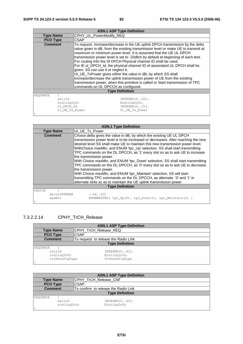
ETSI
ETSI TS 134 123-3 V5.5.0 (2006-06) 823GPP TS 34.123-3 version 5.5.0 Release 5
ASN.1 ASP Type Definition Type Name CPHY_UL_PowerModify_REQ PCO Type CSAP Comment To request increase/decrease in the UE uplink DPCH transmission by the delta
value given in dB, from the existing transmission level or make UE to transmit at maximum or minimum power level. It is assumed that the UE UL DPCH transmission power level is set to -20dbm by default at beginning of each test. For routing Info the Dl DPCH Physical channel ID shall be used. For IE ul_DPCH_Id, the physical channel ID of associated UL DPCH shall be given. SS can use it or neglect it. Ul_UE_TxPower gives either the value in dB, by which SS shall increase/decrease the uplink transmission power of UE from the existing transmission power, when this primitive is called or Start transmission of TPC commands on DL DPCCH as configured
Type Definition SEQUENCE { cellId INTEGER(0..63), routingInfo RoutingInfo, ul_DPCH_Id INTEGER(0..31), ul_UE_Tx_Power Ul_UE_Tx_Power }
ASN.1 Type Definition Type Name Ul_UE_Tx_Power Comment Choice delta gives the value in dB, by which the existing UE UL DPCH
transmission power level is to be increased or decreased. After reaching the new desired level SS shall make UE to maintain this new transmission power level. WithChoice maxMin, and ENUM 'tpc_Up' selection, SS shall start transmitting TPC commands on the DL DPCCH, as '1' every slot so as to ask UE to increase the transmission power. With Choice maxMin, and ENUM 'tpc_Down' selection, SS shall start transmitting TPC commands on the DL DPCCH, as '0' every slot so as to ask UE to decrease the transmission power. With Choice maxMin, and ENUM 'tpc_Maintain' selection, SS will start transmitting TPC commands on the DL DPCCH, as alternate '0' and '1' in alternate slots so as to maintain the UE uplink transmission power
Type Definition CHOICE { deltaINTEGER (-64..63) maxMin ENUMERATED{ tpc_Up(0), tpc_Down(1), tpc_Maintain(2) } }
7.3.2.2.14 CPHY_TrCH_Release
ASN.1 ASP Type Definition Type Name CPHY_TrCH_Release_REQ PCO Type CSAP Comment To request to release the Radio Link
Type Definition SEQUENCE { cellId INTEGER(0..63), routingInfo RoutingInfo, trchConfigType TrchConfigType }
ASN.1 ASP Type Definition Type Name CPHY_TrCH_Release_CNF PCO Type CSAP Comment To confirm to release the Radio Link
Type Definition SEQUENCE { cellId INTEGER(0..63), routingInfo RoutingInfo }
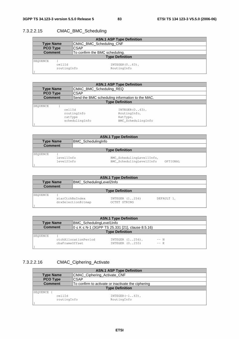
ETSI
ETSI TS 134 123-3 V5.5.0 (2006-06) 833GPP TS 34.123-3 version 5.5.0 Release 5
7.3.2.2.15 CMAC_BMC_Scheduling
ASN.1 ASP Type Definition Type Name CMAC_BMC_Scheduling_CNF PCO Type CSAP Comment To confirm the BMC scheduling.
Type Definition SEQUENCE { cellId INTEGER(0..63), routingInfo RoutingInfo }
ASN.1 ASP Type Definition Type Name CMAC_BMC_Scheduling_REQ PCO Type CSAP Comment Send the BMC scheduling information to the MAC.
Type Definition SEQUENCE { cellId INTEGER(0..63), routingInfo RoutingInfo, ratType RatType, schedulingInfo BMC_SchedulingInfo }
ASN.1 Type Definition Type Name BMC_SchedulingInfo Comment
Type Definition SEQUENCE { level1Info BMC_SchedulingLevel1Info, level2Info BMC_SchedulingLevel2Info OPTIONAL }
ASN.1 Type Definition Type Name BMC_SchedulingLevel2Info Comment
Type Definition SEQUENCE { starCtchBsIndex INTEGER (1..256) DEFAULT 1, drxSelectionBitmap OCTET STRING }
ASN.1 Type Definition Type Name BMC_SchedulingLevel1Info Comment 0 ≤ K ≤ N-1 (3GPP TS 25.331 [21], clause 8.5.16)
Type Definition SEQUENCE { ctchAllocationPeriod INTEGER (1..256), -- N cbsFrameOffset INTEGER (0..255) -- K }
7.3.2.2.16 CMAC_Ciphering_Activate
ASN.1 ASP Type Definition Type Name CMAC_Ciphering_Activate_CNF PCO Type CSAP Comment To confirm to activate or inactivate the ciphering
Type Definition SEQUENCE { cellId INTEGER(-1..63), routingInfo RoutingInfo }

ETSI
ETSI TS 134 123-3 V5.5.0 (2006-06) 843GPP TS 34.123-3 version 5.5.0 Release 5
ASN.1 ASP Type Definition Type Name CMAC_Ciphering_Activate_REQ PCO Type CSAP Comment To request to start or restart downlink ciphering or uplink deciphering.
The physicalChannelIdentity of DPCH applies to routingInfo. Initialize the 20 MSB of HFN component of COUNT-C to the START value stored. If the value of incHFN is set to "NotInc" the SS initializes the remaining LSBs of HFN component in COUNT-C to zero and the SS shall not increment HFN part of COUNT-C at every CFN cycle. If the value of incHFN is set to "IncPerCFN_Cycle" the SS initializes the remainingLSBs of HFN component in COUNT-C accordingly. If it is absent the SS initialize the LSBs of HFN component in COUNT-C to zero, increments the HFN component in COUNT-C by one and then starts the increment HFN part of COUNT-C at every CFN cycle.
Type Definition SEQUENCE { cellId INTEGER(-1..63), routingInfo RoutingInfo, ratType RatType, cn_DomainIdentity CN_DomainIdentity, cipheringModeInfo CipheringModeInfo, incHFN Increment Mode }
ASN.1 Type Definition Type Name Increment_Mode Comment
Type Definition ENUMERATED {incPerCFN_Cycler(0), notInc(1), incByOne_IncPerCFN_Cycle(2)}
7.3.2.2.17 CMAC_Config
ASN.1 ASP Type Definition Type Name CMAC_Config_CNF PCO Type CSAP Comment For MAC emulator to report that a previous attempt to setup, reconfigure or
release a logical channel is successful. Type Definition
SEQUENCE { cellId INTEGER(-1..63), routingInfo RoutingInfo }
ASN.1 ASP Type Definition Type Name CMAC_Config_REQ PCO Type CSAP Comment To request to configure MAC entity. Setup is used for creation of the MAC
instances or the MAC resources. Release is used for free the all MAC resources. The reconfiguration is to change the MAC parameters, it is not the MAC modification.
Type Definition SEQUENCE { cellId INTEGER(-1..63), routingInfo RoutingInfo, ratType RatType, configMessage CHOICE { setup CmacConfigReq, reconfigure CmacConfigReq, release NULL } }
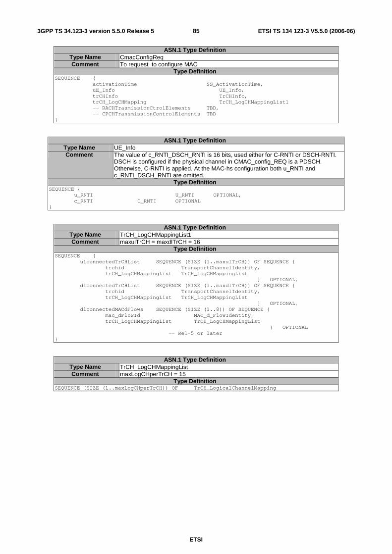
ETSI
ETSI TS 134 123-3 V5.5.0 (2006-06) 853GPP TS 34.123-3 version 5.5.0 Release 5
ASN.1 Type Definition Type Name CmacConfigReq Comment To request to configure MAC
Type Definition SEQUENCE { activationTime SS_ActivationTime, uE_Info UE_Info, trCHInfo TrCHInfo, trCH_LogCHMapping TrCH_LogCHMappingList1 -- RACHTrasmissionCtrolElements TBD, -- CPCHTransmissionControlElements TBD }
ASN.1 Type Definition Type Name UE_Info Comment The value of c_RNTI_DSCH_RNTI is 16 bits, used either for C-RNTI or DSCH-RNTI.
DSCH is configured if the physical channel in CMAC_config_REQ is a PDSCH. Otherwise, C-RNTI is applied. At the MAC-hs configuration both u_RNTI and c_RNTI_DSCH_RNTI are omitted.
Type Definition SEQUENCE { u_RNTI U_RNTI OPTIONAL, c_RNTI C_RNTI OPTIONAL }
ASN.1 Type Definition Type Name TrCH_LogCHMappingList1 Comment maxulTrCH = maxdlTrCH = 16
Type Definition SEQUENCE { ulconnectedTrCHList SEQUENCE (SIZE (1..maxulTrCH)) OF SEQUENCE { trchid TransportChannelIdentity, trCH_LogCHMappingList TrCH_LogCHMappingList } OPTIONAL, dlconnectedTrCHList SEQUENCE (SIZE (1..maxdlTrCH)) OF SEQUENCE { trchid TransportChannelIdentity, trCH_LogCHMappingList TrCH_LogCHMappingList } OPTIONAL, dlconnectedMACdFlows SEQUENCE (SIZE (1..8)) OF SEQUENCE { mac_dFlowId MAC_d_FlowIdentity, trCH_LogCHMappingList TrCH_LogCHMappingList } OPTIONAL -- Rel-5 or later }
ASN.1 Type Definition Type Name TrCH_LogCHMappingList Comment maxLogCHperTrCH = 15
Type Definition SEQUENCE (SIZE (1..maxLogCHperTrCH)) OF TrCH_LogicalChannelMapping
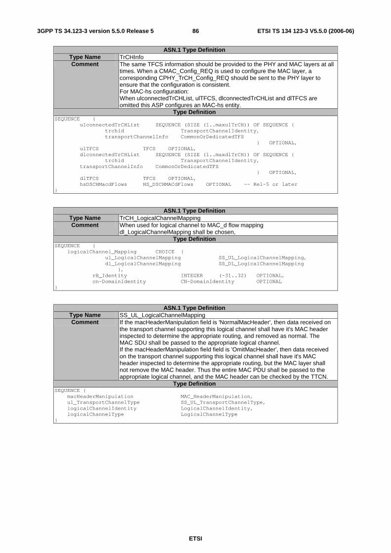
ETSI
ETSI TS 134 123-3 V5.5.0 (2006-06) 863GPP TS 34.123-3 version 5.5.0 Release 5
ASN.1 Type Definition Type Name TrCHInfo Comment The same TFCS information should be provided to the PHY and MAC layers at all
times. When a CMAC_Config_REQ is used to configure the MAC layer, a corresponding CPHY_TrCH_Config_REQ should be sent to the PHY layer to ensure that the configuration is consistent. For MAC-hs configuration: When ulconnectedTrCHList, ulTFCS, dlconnectedTrCHList and dlTFCS are omitted this ASP configures an MAC-hs entity.
Type Definition SEQUENCE { ulconnectedTrCHList SEQUENCE (SIZE (1..maxulTrCH)) OF SEQUENCE { trchid TransportChannelIdentity, transportChannelInfo CommonOrDedicatedTFS } OPTIONAL, ulTFCS TFCS OPTIONAL, dlconnectedTrCHList SEQUENCE (SIZE (1..maxdlTrCH)) OF SEQUENCE { trchid TransportChannelIdentity, transportChannelInfo CommonOrDedicatedTFS } OPTIONAL, dlTFCS TFCS OPTIONAL, hsDSCHMacdFlows HS_DSCHMACdFlows OPTIONAL -- Rel-5 or later }
ASN.1 Type Definition Type Name TrCH_LogicalChannelMapping Comment When used for logical channel to MAC_d flow mapping
dl_LogicalChannelMapping shall be chosen, Type Definition
SEQUENCE { logicalChannel_Mapping CHOICE { ul_LogicalChannelMapping SS_UL_LogicalChannelMapping, dl_LogicalChannelMapping SS_DL_LogicalChannelMapping }, rB_Identity INTEGER (-31..32) OPTIONAL, cn-DomainIdentity CN-DomainIdentity OPTIONAL }
ASN.1 Type Definition Type Name SS_UL_LogicalChannelMapping Comment If the macHeaderManipulation field is 'NormalMacHeader', then data received on
the transport channel supporting this logical channel shall have it's MAC header inspected to determine the appropriate routing, and removed as normal. The MAC SDU shall be passed to the appropriate logical channel. If the macHeaderManipulation field field is 'OmitMacHeader', then data received on the transport channel supporting this logical channel shall have it's MAC header inspected to determine the appropriate routing, but the MAC layer shall not remove the MAC header. Thus the entire MAC PDU shall be passed to the appropriate logical channel, and the MAC header can be checked by the TTCN.
Type Definition SEQUENCE { macHeaderManipulation MAC_HeaderManipulation, ul_TransportChannelType SS_UL_TransportChannelType, logicalChannelIdentity LogicalChannelIdentity, logicalChannelType LogicalChannelType }

ETSI
ETSI TS 134 123-3 V5.5.0 (2006-06) 873GPP TS 34.123-3 version 5.5.0 Release 5
ASN.1 Type Definition Type Name SS_DL_LogicalChannelMapping Comment If the macHeaderManipulation field is 'NormalMacHeader', then data transmitted
on this logical channel shall have an appropriate MAC header added before it is sent to lower layers for transmission. If the macHeaderManipulation field is 'OmitMacHeader', then data transmitted on this logical channel shall not have any MAC header information added, even if the logical channel type and mapping indicates that there should be a MAC header present. This allows the entire MAC PDU to be specified in the TTCN, so individual fields in the MAC header can be modified. When used for DTCH mapping to MAC_d flow, rlc_SizeList shall choose "configured" according to the configured mAChsAddReconfQueue valules.
Type Definition SEQUENCE { macHeaderManipulation MAC_HeaderManipulation, dlTransportChannelType SS_DL_TransportChannelType, logicalChannelIdentity LogicalChannelIdentity, logicalChannelType LogicalChannelType, rlc_SizeList CHOICE { allSizes NULL, configured NULL, explicitList RLC_SizeExplicitList}, mac_LogicalChannelPriority MAC_LogicalChannelPriority OPTIONAL }
ASN.1 Type Definition Type Name SS_UL_TransportChannelType Comment
Type Definition ENUMERATED { dch (0), rach (1), cpch (2), usch (3), edch (4) -- Rel-6 or later }
ASN.1 Type Definition Type Name MAC_LogicalChannelPriority Comment
Type Definition INTEGER (1..8)
ASN.1 Type Definition Type Name SS_DL_TransportChannelType Comment
Type Definition ENUMERATED { dch (0), fach (1), bch (2), pch (3), dsch (4), hsdsch (5) -- Rel-5 or later }

ETSI
ETSI TS 134 123-3 V5.5.0 (2006-06) 883GPP TS 34.123-3 version 5.5.0 Release 5
ASN.1 Type Definition Type Name LogicalChannelType Comment
Type Definition ENUMERATED { bCCH (0), pCCH (1), cCCH (2), cTCH (3), dCCH (4), dTCH (5), sHCCH (6) }
ASN.1 Type Definition Type Name MAC_HeaderManipulation Comment
Type Definition ENUMERATED { normalMacHeader (0), omitMacHeader (1) }
7.3.2.2.17a CMAC_MAChs_TFRCconfigure (Rel-5 or later)
ASN.1 ASP Type Definition Type Name CMAC_MAChs_TFRCconfigure_CNF PCO Type CSAP Comment Applicable Rel-5 or later
Confirm a previous CMAC_MAChs_TFRCconfigure_REQ being successful. Type Definition
SEQUENCE { cellId INTEGER(-1..63) }

ETSI
ETSI TS 134 123-3 V5.5.0 (2006-06) 893GPP TS 34.123-3 version 5.5.0 Release 5
ASN.1 ASP Type Definition Type Name CMAC_MAChs_TFRCconfigure_REQ PCO Type CSAP Comment Applicable Rel-5 or later
To configure the TFRC selection in the MAC-hs entity, channelisationCodeOffset + noOfChannelisationCodes shall not be great than 15. If explicitlyConfigured is selected in tfrcConfigMode, the SS shall use all the parameter values specified to configure a correct transport format and radio resources. If sS_Configured is selected, the parameter value range is specified. SS shall dynamically select the suitable values for the parameters "modulationScheme", "channelisationCodeOffset", "noOfChannelisatonCodes ", tbSizeIndexOnHS_SCCH", "redundancyVersion" and "hs_PDSCH_TxPower" according to UE's capability category and CQI information reported by the UE.
Type Definition SEQUENCE { cellId INTEGER(-1..63), tfrcConfigMode CHOICE { explicitlyConfigured SEQUENCE { modulationScheme ModulationScheme, channelisationCodeOffset INTEGER (1..14), noOfChannelisatonCodes INTEGER (1..15), tbSizeIndexOnHS_SCCH INTEGER (0..63), minimumInterTTIinterval INTEGER (1..3), redundancyVersion INTEGER (0..7), hs_PDSCH_TxPower DL_TxPower -- default offset related -- to p-CPICH or s-CPICH }, sS_Configured SEQUENCE { minChannelisationCodeOffset INTEGER (1..14), maxNoOfChannelisatonCodes INTEGER (1..15), iniHS_PDSCH_TxPower DL_TxPower -- default offset related -- to p-CPICH or s-CPICH } } }
ASN.1 Type Definition Type Name ModulationScheme Comment
Type Definition ENUMERATED {qpsk (0), qam16 (1)}
ASN.1 ASP Type Definition Type Name CMAC_MAChs_HARQprocAsign_CNF PCO Type CSAP Comment Applicable Rel-5 or later
Confirm a previous CMAC_MAChs_HARQprocAsign_REQ being successful. Type Definition
SEQUENCE { cellId INTEGER(-1..63) }
ASN.1 ASP Type Definition Type Name CMAC_MAChs_HARQprocAsign_REQ PCO Type CSAP Comment Applicable Rel-5 or later
To assign a HARQ process handling the next MAC-hs PDU transmission. This ASP provides TTCN the ability to select an HARQ process serving the next MAC-hs PDU which follows the ASP. After successful transmission the MAC-hs returns back to normal operation. In the normal operation a suitable HARQ process is selected by HARQ entity in the MAC-hs to serve the MAC-hs PDU without TTCN intervening.
Type Definition SEQUENCE { cellId INTEGER(-1..63), harqProcessId INTEGER(0..7) }
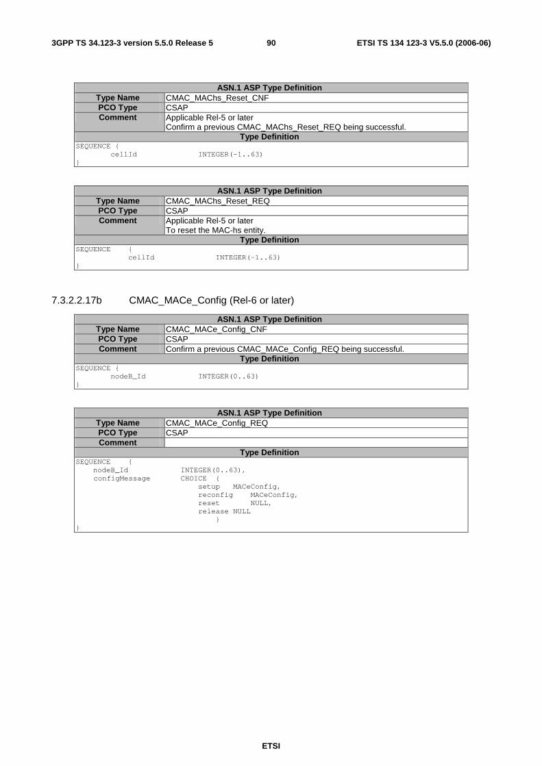
ETSI
ETSI TS 134 123-3 V5.5.0 (2006-06) 903GPP TS 34.123-3 version 5.5.0 Release 5
ASN.1 ASP Type Definition Type Name CMAC_MAChs_Reset_CNF PCO Type CSAP Comment Applicable Rel-5 or later
Confirm a previous CMAC_MAChs_Reset_REQ being successful. Type Definition
SEQUENCE { cellId INTEGER(-1..63) }
ASN.1 ASP Type Definition Type Name CMAC_MAChs_Reset_REQ PCO Type CSAP Comment Applicable Rel-5 or later
To reset the MAC-hs entity. Type Definition
SEQUENCE { cellId INTEGER(-1..63) }
7.3.2.2.17b CMAC_MACe_Config (Rel-6 or later)
ASN.1 ASP Type Definition Type Name CMAC_MACe_Config_CNF PCO Type CSAP Comment Confirm a previous CMAC_MACe_Config_REQ being successful.
Type Definition SEQUENCE { nodeB_Id INTEGER(0..63) }
ASN.1 ASP Type Definition Type Name CMAC_MACe_Config_REQ PCO Type CSAP Comment
Type Definition SEQUENCE { nodeB_Id INTEGER(0..63),
configMessage CHOICE { setup MACeConfig, reconfig MACeConfig, reset NULL, release NULL }
}

ETSI
ETSI TS 134 123-3 V5.5.0 (2006-06) 913GPP TS 34.123-3 version 5.5.0 Release 5
ASN.1 Type Definition Type Name MACeConfig Comment If the macHeaderManipulation field is 'NormalMacHeader' in ddiMappingList, then
data received on the E-DCH (MAC_e PDU) shall have it's MAC header inspected to de-multiplex and to determine the appropriate routing, and the MACes PDU shall be passed to the MAC_es together with the relevant DDI, N, CFN and subframe number. If the macHeaderManipulation field field is 'OmitMacHeader', then data received on the E-DCH (MAC_e PDU) shall have it's MAC header inspected to de-multiplex and to determine the appropriate routing, then the MAC_e layer shall delivery the MAC-es PDU, SI and the related CFN, subframe number to the MAC_es entity. connectedToMAC_es field is used to provide the possibility that the E-DCH-MACdFlows from only one MAC_e entity are connected to the MAC_es entity in the inter node B soft handover test cases
Type Definition SEQUENCE { activationTime SS_ActivationTime, ddiMappinglist DDI_MappingList, e_DCHMacdFlows E_DCHMACdFlows, connectedToMAC_es BOOLEAN DEFAULT TRUE –- can be set to FALSE in inter nodeB SHO }
7.3.2.2.17c CMAC_MACe_NodeB_CellMapping (Rel-6 or later)
ASN.1 ASP Type Definition Type Name CMAC_MACe_NodeB_CellMapping_CNF PCO Type CSAP Comment Confirm a previous CMAC_MACe_NodeB_CellMapping_REQ being successful.
Type Definition SEQUENCE { nodeB_Id INTEGER(0..63) }
ASN.1 ASP Type Definition Type Name CMAC_MACe_NodeB_CellMapping_REQ PCO Type CSAP Comment To put a set of cells under the control of a MAC_e entity indicated by nodeB_Id,
which is configured by CMAC_MAC_e_Config_REQ. This ASP establishes the routing relation between E-DCH related channels in these cells with a MAC_e entity. A cell is mapped to only one NodeB, and the cellId allocation is unique in a test.
Type Definition SEQUENCE { nodeB_Id INTEGER(0..63), celllist SEQUENCE OF INTEGER (0..63) }
7.3.2.2.17d CMAC_MACes_Config (Rel-6 or later)
ASN.1 ASP Type Definition Type Name CMAC_MACes_Config_CNF PCO Type CSAP Comment Confirm a previous CMAC_MACes_Config_REQ being successful.
Type Definition SEQUENCE { confirm NULL }
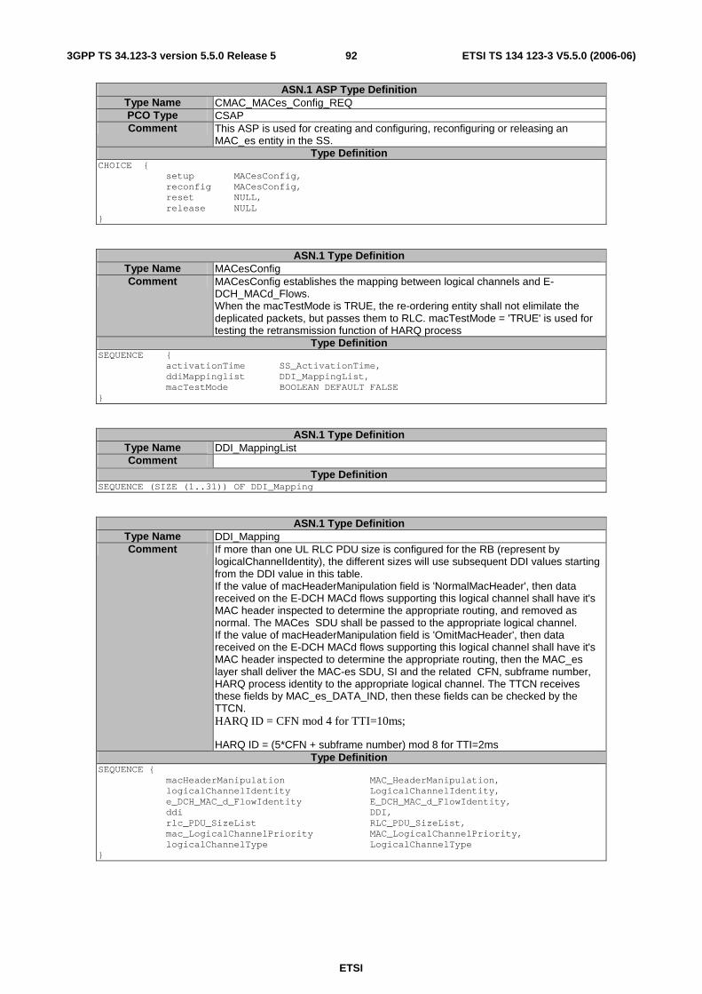
ETSI
ETSI TS 134 123-3 V5.5.0 (2006-06) 923GPP TS 34.123-3 version 5.5.0 Release 5
ASN.1 ASP Type Definition Type Name CMAC_MACes_Config_REQ PCO Type CSAP Comment This ASP is used for creating and configuring, reconfiguring or releasing an
MAC_es entity in the SS. Type Definition
CHOICE { setup MACesConfig, reconfig MACesConfig, reset NULL, release NULL }
ASN.1 Type Definition Type Name MACesConfig Comment MACesConfig establishes the mapping between logical channels and E-
DCH_MACd_Flows. When the macTestMode is TRUE, the re-ordering entity shall not elimilate the deplicated packets, but passes them to RLC. macTestMode = 'TRUE' is used for testing the retransmission function of HARQ process
Type Definition SEQUENCE { activationTime SS_ActivationTime, ddiMappinglist DDI_MappingList, macTestMode BOOLEAN DEFAULT FALSE }
ASN.1 Type Definition Type Name DDI_MappingList Comment
Type Definition SEQUENCE (SIZE (1..31)) OF DDI_Mapping
ASN.1 Type Definition Type Name DDI_Mapping Comment If more than one UL RLC PDU size is configured for the RB (represent by
logicalChannelIdentity), the different sizes will use subsequent DDI values starting from the DDI value in this table. If the value of macHeaderManipulation field is 'NormalMacHeader', then data received on the E-DCH MACd flows supporting this logical channel shall have it's MAC header inspected to determine the appropriate routing, and removed as normal. The MACes SDU shall be passed to the appropriate logical channel. If the value of macHeaderManipulation field is 'OmitMacHeader', then data received on the E-DCH MACd flows supporting this logical channel shall have it's MAC header inspected to determine the appropriate routing, then the MAC_es layer shall deliver the MAC-es SDU, SI and the related CFN, subframe number, HARQ process identity to the appropriate logical channel. The TTCN receives these fields by MAC_es_DATA_IND, then these fields can be checked by the TTCN. HARQ ID = CFN mod 4 for TTI=10ms;
HARQ ID = (5*CFN + subframe number) mod 8 for TTI=2ms Type Definition
SEQUENCE { macHeaderManipulation MAC_HeaderManipulation, logicalChannelIdentity LogicalChannelIdentity, e_DCH_MAC_d_FlowIdentity E_DCH_MAC_d_FlowIdentity, ddi DDI, rlc_PDU_SizeList RLC_PDU_SizeList, mac_LogicalChannelPriority MAC_LogicalChannelPriority, logicalChannelType LogicalChannelType }

ETSI
ETSI TS 134 123-3 V5.5.0 (2006-06) 933GPP TS 34.123-3 version 5.5.0 Release 5
7.3.2.2.17e CMAC_MACe_AG (Rel-6 or later)
ASN.1 ASP Type Definition Type Name CMAC_MACe_AG_CNF PCO Type CSAP Comment Confirm a previous CMAC_MACe_AG_REQ being successful.
Type Definition SEQUENCE { nodeBId INTEGER(0..63) }
ASN.1 ASP Type Definition Type Name CMAC_MACe_AG_REQ PCO Type CSAP Comment The hARQProcId shall be converted to the nearest CFN (and subframe number if
TTI = 2ms) by the SS, and the Absolute Grant is sent in that CFN (and subframe number if TTI = 2ms)
Type Definition SEQUENCE { nodeB_Id INTEGER(0..63), grantType ENUMERATED {primary(0), secondary(1)}, absoluteGrantValue BIT STRING(SIZE(5)), absoluteGrantScope BIT STRING(SIZE(1)), hARQProcId INTEGER (0..7) }
7.3.2.2.17f CMAC_MACe_AckNack (Rel-6 or later)
ASN.1 ASP Type Definition Type Name CMAC_MACe_AckNack_CNF PCO Type CSAP Comment To Confirm CMAC_e_AckNack_REQ
Type Definition SEQUENCE { nodeB_Id INTEGER(0..63) }
ASN.1 ASP Type Definition Type Name CMAC_MACe_AckNack_REQ PCO Type CSAP Comment To request the SS to set operation mode of the Ack/Nack function for the HARQ
process hARQProcId. At the SS initialisation Ack/Nack function is in normal operation mode
Type Definition SEQUENCE { nodeB_Id INTEGER(0..63), hARQProcId INTEGER (0..7), –- only (0..3) allowes for TTI = 10 ms ackNackFunction AckNackFunction }
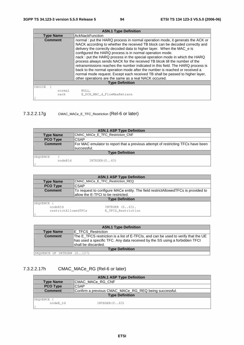
ETSI
ETSI TS 134 123-3 V5.5.0 (2006-06) 943GPP TS 34.123-3 version 5.5.0 Release 5
ASN.1 Type Definition Type Name AckNackFunction Comment normal : put the HARQ process in normal operation mode, it generats the ACK or
NACK according to whether the received TB block can be decoded correctly and delivery the correctly decoded data to higher layer. When the MAC_e is configured the HARQ process is in normal operation mode. nack : put the HARQ process in the special operation mode in which the HARQ process always sends NACK for the received TB blcok till the number of the retransmissions reaches the number indicated in this field. The HARQ process is back to the normal operation mode after the number is reached or received a normal mode request. Except each received TB shall be passed to higher layer, other operations are the same as a real NACK occured.
Type Definition CHOICE { normal NULL, nack E_DCH_MAC_d_FlowMaxRetrans }
7.3.2.2.17g CMAC_MACe_E_TFC_Restriction (Rel-6 or later)
ASN.1 ASP Type Definition Type Name CMAC_MACe_E_TFC_Restriction_CNF PCO Type CSAP Comment For MAC emulator to report that a previous attempt of restricting TFCs have been
successful. Type Definition
SEQUENCE { nodeBId INTEGER(0..63) }
ASN.1 ASP Type Definition Type Name CMAC_MACe_E_TFC_Restriction_REQ PCO Type CSAP Comment To request to configure MACe entity. The field restrictAllowedTFCs is provided to
allow the E-TFCI to be restricted. Type Definition
SEQUENCE { nodeBId INTEGER (0..63), restrictAllowedTFCs E_TFCS_Restriction }
ASN.1 Type Definition Type Name E_TFCS_Restriction Comment The E_TFCS restriction is a list of E-TFCIs, and can be used to verify that the UE
has used a specific TFC. Any data received by the SS using a forbidden TFCI shall be discarded.
Type Definition SEQUENCE OF INTEGER (0..127)
7.3.2.2.17h CMAC_MACe_RG (Rel-6 or later)
ASN.1 ASP Type Definition Type Name CMAC_MACe_RG_CNF PCO Type CSAP Comment Confirm a previous CMAC_MACe_RG_REQ being successful.
Type Definition SEQUENCE { nodeB_Id INTEGER(0..63) }
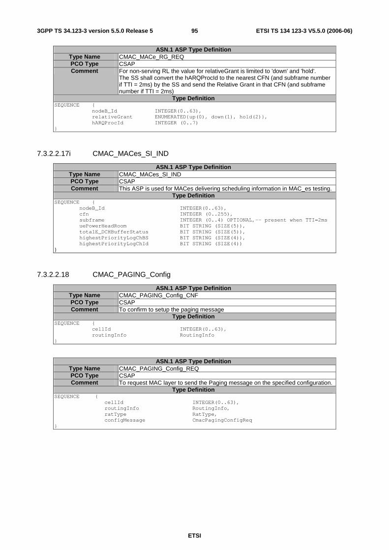
ETSI
ETSI TS 134 123-3 V5.5.0 (2006-06) 953GPP TS 34.123-3 version 5.5.0 Release 5
ASN.1 ASP Type Definition Type Name CMAC_MACe_RG_REQ PCO Type CSAP Comment For non-serving RL the value for relativeGrant is limited to 'down' and 'hold'.
The SS shall convert the hARQProcId to the nearest CFN (and subframe number if TTI = 2ms) by the SS and send the Relative Grant in that CFN (and subframe number if TTI = 2ms)
Type Definition SEQUENCE { nodeB_Id INTEGER(0..63), relativeGrant ENUMERATED{up(0), down(1), hold(2)}, hARQProcId INTEGER (0..7) }
7.3.2.2.17i CMAC_MACes_SI_IND
ASN.1 ASP Type Definition Type Name CMAC_MACes_SI_IND PCO Type CSAP Comment This ASP is used for MACes delivering scheduling information in MAC_es testing.
Type Definition SEQUENCE { nodeB_Id INTEGER(0..63), cfn INTEGER (0..255), subframe INTEGER (0..4) OPTIONAL,-- present when TTI=2ms uePowerHeadRoom BIT STRING (SIZE(5)), totalE_DCHBufferStatus BIT STRING (SIZE(5)), highestPriorityLogChBS BIT STRING (SIZE(4)), highestPriorityLogChId BIT STRING (SIZE(4)) }
7.3.2.2.18 CMAC_PAGING_Config
ASN.1 ASP Type Definition Type Name CMAC_PAGING_Config_CNF PCO Type CSAP Comment To confirm to setup the paging message
Type Definition SEQUENCE { cellId INTEGER(0..63), routingInfo RoutingInfo }
ASN.1 ASP Type Definition Type Name CMAC_PAGING_Config_REQ PCO Type CSAP Comment To request MAC layer to send the Paging message on the specified configuration.
Type Definition SEQUENCE { cellId INTEGER(0..63), routingInfo RoutingInfo, ratType RatType, configMessage CmacPagingConfigReq }
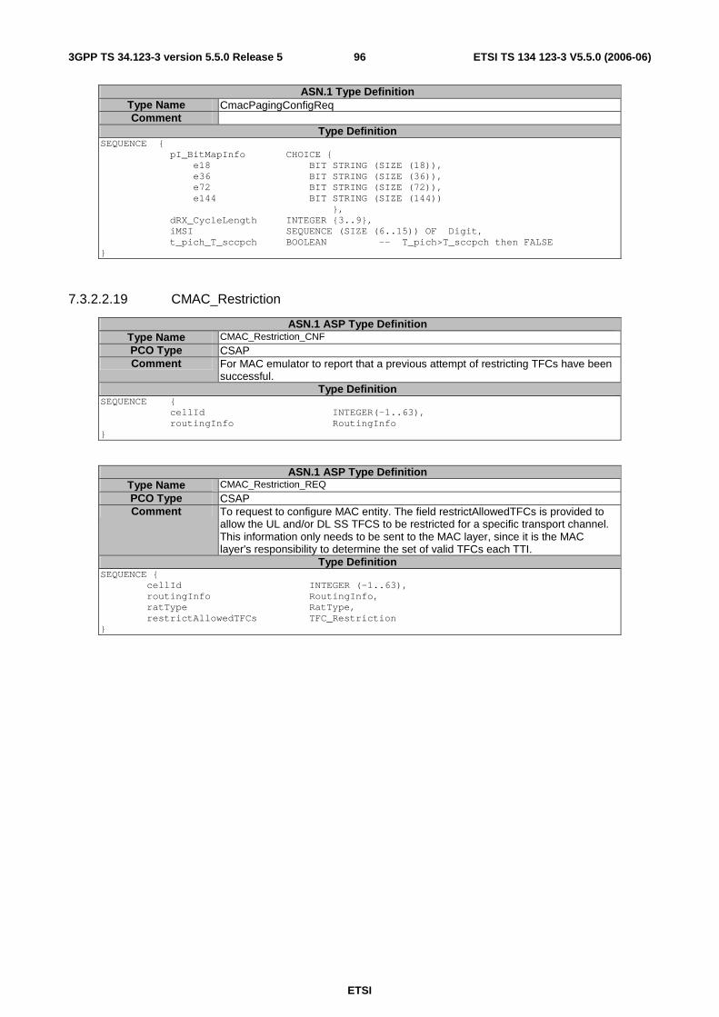
ETSI
ETSI TS 134 123-3 V5.5.0 (2006-06) 963GPP TS 34.123-3 version 5.5.0 Release 5
ASN.1 Type Definition Type Name CmacPagingConfigReq Comment
Type Definition SEQUENCE { pI_BitMapInfo CHOICE { e18 BIT STRING (SIZE (18)), e36 BIT STRING (SIZE (36)), e72 BIT STRING (SIZE (72)), e144 BIT STRING (SIZE (144)) }, dRX_CycleLength INTEGER {3..9}, iMSI SEQUENCE (SIZE (6..15)) OF Digit, t_pich_T_sccpch BOOLEAN -- T_pich>T_sccpch then FALSE }
7.3.2.2.19 CMAC_Restriction
ASN.1 ASP Type Definition Type Name CMAC_Restriction_CNF PCO Type CSAP Comment For MAC emulator to report that a previous attempt of restricting TFCs have been
successful. Type Definition
SEQUENCE { cellId INTEGER(-1..63), routingInfo RoutingInfo }
ASN.1 ASP Type Definition Type Name CMAC_Restriction_REQ PCO Type CSAP Comment To request to configure MAC entity. The field restrictAllowedTFCs is provided to
allow the UL and/or DL SS TFCS to be restricted for a specific transport channel. This information only needs to be sent to the MAC layer, since it is the MAC layer's responsibility to determine the set of valid TFCs each TTI.
Type Definition SEQUENCE { cellId INTEGER (-1..63), routingInfo RoutingInfo, ratType RatType, restrictAllowedTFCs TFC_Restriction }
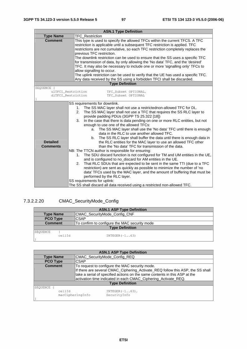
ETSI
ETSI TS 134 123-3 V5.5.0 (2006-06) 973GPP TS 34.123-3 version 5.5.0 Release 5
ASN.1 Type Definition Type Name TFC_Restriction Comment This type is used to specify the allowed TFCs within the current TFCS. A TFC
restriction is applicable until a subsequent TFC restriction is applied. TFC restrictions are not cumulative, so each TFC restriction completely replaces the previous TFC restriction. The downlink restriction can be used to ensure that the SS uses a specific TFC for transmission of data, by only allowing the 'No data' TFC, and the 'desired' TFC. It may also be necessary to include one or more 'signalling only' TFCs to allow signalling to occur. The uplink restriction can be used to verify that the UE has used a specific TFC. Any data received by the SS using a forbidden TFCI shall be discarded.
Type Definition SEQUENCE { ulTFCI_Restriction TFC_Subset OPTIONAL, dlTFCI_Restriction TFC_Subset OPTIONAL }
Detailed Comments
SS requirements for downlink. 1. The SS MAC layer shall not use a restrictednon-allowed TFC for DL. 2. The SS MAC layer shall not use a TFC that requires the SS RLC layer to
provide padding PDUs (3GPP TS 25.322 [18]) 3. In the case that there is data pending on one or more RLC entities, but not
enough to use one of the allowed TFCs: a. The SS MAC layer shall use the 'No data' TFC until there is enough
data in the RLC to use another allowed TFC. b. The SS RLC layer shall buffer the data until there is enough data in
the RLC entities for the MAC layer to use an allowed TFC other than the 'No data' TFC for transmission of the data.
NB: The TTCN author is responsible for ensuring: 1. The SDU discard function is not configured for TM and UM entities in the UE,
and is configured to no_discard for AM entities in the UE. 2. That RLC SDUs that are expected to be sent in the same TTI (due to a TFC
restriction) are sent as quickly as possible to minimize the number of 'no data' TFCs used by the MAC layer, and the amount of buffering that must be performed by the RLC layer.
SS requirements for uplink: The SS shall discard all data received using a restricted non-allowed TFC.
7.3.2.2.20 CMAC_SecurityMode_Config
ASN.1 ASP Type Definition Type Name CMAC_SecurityMode_Config_CNF PCO Type CSAP Comment To confirm to configure the MAC security mode
Type Definition SEQUENCE { cellId INTEGER(-1..63) }
ASN.1 ASP Type Definition Type Name CMAC_SecurityMode_Config_REQ PCO Type CSAP Comment To request to configure the MAC security mode.
If there are several CMAC_Ciphering_Activate_REQ follow this ASP, the SS shall take a serial of specified actions on the same contents in this ASP at the activation time indicated in each CMAC_Ciphering_Activate_REQ.
Type Definition SEQUENCE { cellId INTEGER(-1..63), macCipheringInfo SecurityInfo }
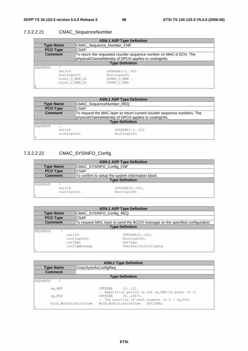
ETSI
ETSI TS 134 123-3 V5.5.0 (2006-06) 983GPP TS 34.123-3 version 5.5.0 Release 5
7.3.2.2.21 CMAC_SequenceNumber
ASN.1 ASP Type Definition Type Name CMAC_Sequence_Number_CNF PCO Type CSAP Comment To return the requested counter sequence number on MAC-d DCH. The
physicalChannelIdentity of DPCH applies to routingInfo. Type Definition
SEQUENCE { cellId INTEGER(-1..63), routingInfo RoutingInfo, count_C_MSB_UL COUNT_C_MSB , count_C_MSB_DL COUNT_C_MSB }
ASN.1 ASP Type Definition Type Name CMAC_SequenceNumber_REQ PCO Type CSAP Comment To request the MAC layer to return current counter sequence numbers. The
physicalChannelIdentity of DPCH applies to routingInfo. Type Definition
SEQUENCE { cellId INTEGER(-1..63), routingInfo RoutingInfo }
7.3.2.2.22 CMAC_SYSINFO_Config
ASN.1 ASP Type Definition Type Name CMAC_SYSINFO_Config_CNF PCO Type CSAP Comment To confirm to setup the system information block
Type Definition SEQUENCE { cellId INTEGER(0..63), routingInfo RoutingInfo }
ASN.1 ASP Type Definition Type Name CMAC_SYSINFO_Config_REQ PCO Type CSAP Comment To request MAC layer to send the BCCH message on the specified configuration.
Type Definition SEQUENCE { cellId INTEGER(0..63), routingInfo RoutingInfo, ratType RatType, configMessage CmacSysinfoConfigReq }
ASN.1 Type Definition Type Name CmacSysinfoConfigReq Comment
Type Definition SEQUENCE { sg_REP INTEGER (2..12), -- Repetition period is the sg_REP-th power of 2. sg_POS INTEGER (0..2047), -- The position of each segment is 2 * sg_POS. bcch_ModificationTime BCCH_ModificationTime OPTIONAL }
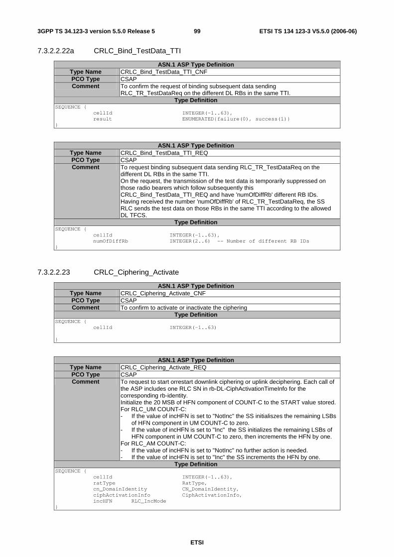
ETSI
ETSI TS 134 123-3 V5.5.0 (2006-06) 993GPP TS 34.123-3 version 5.5.0 Release 5
7.3.2.2.22a CRLC_Bind_TestData_TTI
ASN.1 ASP Type Definition Type Name CRLC_Bind_TestData_TTI_CNF PCO Type CSAP Comment To confirm the request of binding subsequent data sending
RLC_TR_TestDataReq on the different DL RBs in the same TTI. Type Definition
SEQUENCE { cellId INTEGER(-1..63), result ENUMERATED{failure(0), success(1)} }
ASN.1 ASP Type Definition Type Name CRLC_Bind_TestData_TTI_REQ PCO Type CSAP Comment To request binding subsequent data sending RLC_TR_TestDataReq on the
different DL RBs in the same TTI. On the request, the transmission of the test data is temporarily suppressed on those radio bearers which follow subsequently this CRLC_Bind_TestData_TTI_REQ and have 'numOfDiffRb' different RB IDs. Having received the number 'numOfDiffRb' of RLC_TR_TestDataReq, the SS RLC sends the test data on those RBs in the same TTI according to the allowed DL TFCS.
Type Definition SEQUENCE { cellId INTEGER(-1..63), numOfDiffRb INTEGER(2..6) -- Number of different RB IDs }
7.3.2.2.23 CRLC_Ciphering_Activate
ASN.1 ASP Type Definition Type Name CRLC_Ciphering_Activate_CNF PCO Type CSAP Comment To confirm to activate or inactivate the ciphering
Type Definition SEQUENCE { cellId INTEGER(-1..63) }
ASN.1 ASP Type Definition Type Name CRLC_Ciphering_Activate_REQ PCO Type CSAP Comment To request to start orrestart downlink ciphering or uplink deciphering. Each call of
the ASP includes one RLC SN in rb-DL-CiphActivationTimeInfo for the corresponding rb-identity. Initialize the 20 MSB of HFN component of COUNT-C to the START value stored. For RLC_UM COUNT-C: - If the value of incHFN is set to "NotInc" the SS initialiszes the remaining LSBs
of HFN component in UM COUNT-C to zero. - If the value of incHFN is set to "Inc" the SS initializes the remaining LSBs of
HFN component in UM COUNT-C to zero, then increments the HFN by one. For RLC_AM COUNT-C: - If the value of incHFN is set to "NotInc" no further action is needed. - If the value of incHFN is set to "Inc" the SS increments the HFN by one.
Type Definition SEQUENCE { cellId INTEGER(-1..63), ratType RatType, cn_DomainIdentity CN_DomainIdentity, ciphActivationInfo CiphActivationInfo, incHFN RLC_IncMode }
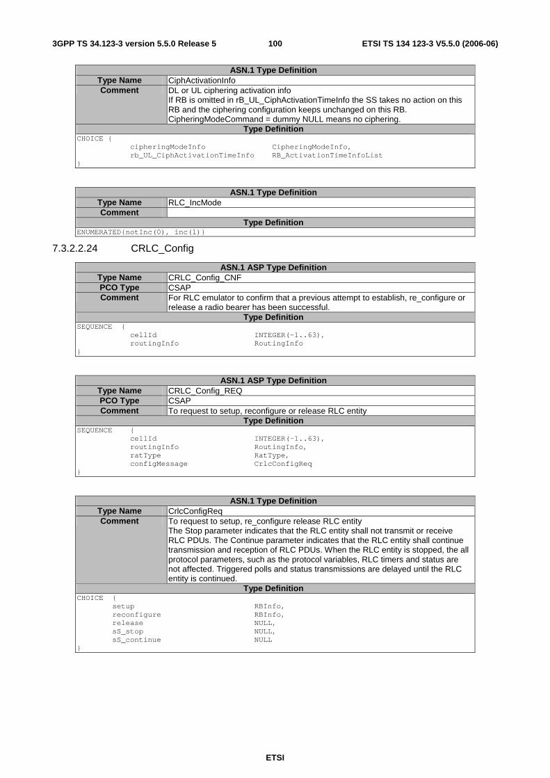
ETSI
ETSI TS 134 123-3 V5.5.0 (2006-06) 1003GPP TS 34.123-3 version 5.5.0 Release 5
ASN.1 Type Definition Type Name CiphActivationInfo Comment DL or UL ciphering activation info
If RB is omitted in rB_UL_CiphActivationTimeInfo the SS takes no action on this RB and the ciphering configuration keeps unchanged on this RB. CipheringModeCommand = dummy NULL means no ciphering.
Type Definition CHOICE { cipheringModeInfo CipheringModeInfo, rb_UL_CiphActivationTimeInfo RB_ActivationTimeInfoList }
ASN.1 Type Definition Type Name RLC_IncMode Comment
Type Definition ENUMERATED{notInc(0), inc(1)}
7.3.2.2.24 CRLC_Config
ASN.1 ASP Type Definition Type Name CRLC_Config_CNF PCO Type CSAP Comment For RLC emulator to confirm that a previous attempt to establish, re_configure or
release a radio bearer has been successful. Type Definition
SEQUENCE { cellId INTEGER(-1..63), routingInfo RoutingInfo }
ASN.1 ASP Type Definition Type Name CRLC_Config_REQ PCO Type CSAP Comment To request to setup, reconfigure or release RLC entity
Type Definition SEQUENCE { cellId INTEGER(-1..63), routingInfo RoutingInfo, ratType RatType, configMessage CrlcConfigReq }
ASN.1 Type Definition Type Name CrlcConfigReq Comment To request to setup, re_configure release RLC entity
The Stop parameter indicates that the RLC entity shall not transmit or receive RLC PDUs. The Continue parameter indicates that the RLC entity shall continue transmission and reception of RLC PDUs. When the RLC entity is stopped, the all protocol parameters, such as the protocol variables, RLC timers and status are not affected. Triggered polls and status transmissions are delayed until the RLC entity is continued.
Type Definition CHOICE { setup RBInfo, reconfigure RBInfo, release NULL, sS_stop NULL, sS_continue NULL }
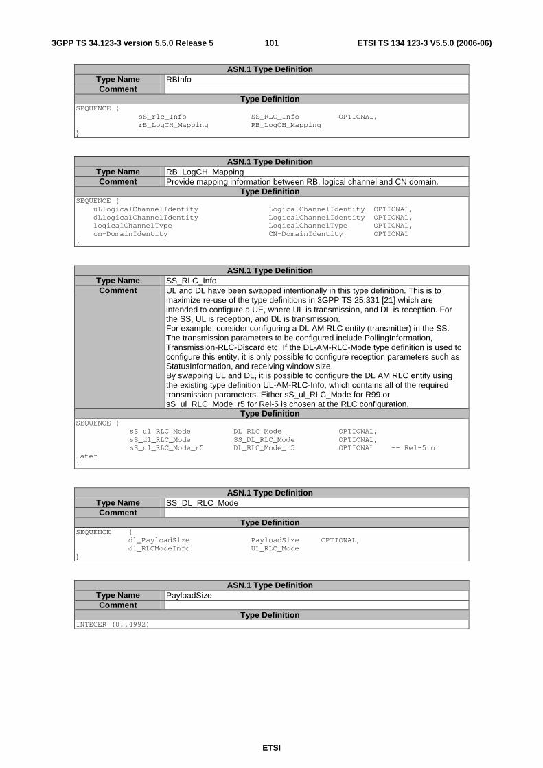
ETSI
ETSI TS 134 123-3 V5.5.0 (2006-06) 1013GPP TS 34.123-3 version 5.5.0 Release 5
ASN.1 Type Definition Type Name RBInfo Comment
Type Definition SEQUENCE { sS_rlc_Info SS_RLC_Info OPTIONAL, rB_LogCH_Mapping RB_LogCH_Mapping }
ASN.1 Type Definition Type Name RB_LogCH_Mapping Comment Provide mapping information between RB, logical channel and CN domain.
Type Definition SEQUENCE { uLlogicalChannelIdentity LogicalChannelIdentity OPTIONAL, dLlogicalChannelIdentity LogicalChannelIdentity OPTIONAL, logicalChannelType LogicalChannelType OPTIONAL, cn-DomainIdentity CN-DomainIdentity OPTIONAL }
ASN.1 Type Definition Type Name SS_RLC_Info Comment UL and DL have been swapped intentionally in this type definition. This is to
maximize re-use of the type definitions in 3GPP TS 25.331 [21] which are intended to configure a UE, where UL is transmission, and DL is reception. For the SS, UL is reception, and DL is transmission. For example, consider configuring a DL AM RLC entity (transmitter) in the SS. The transmission parameters to be configured include PollingInformation, Transmission-RLC-Discard etc. If the DL-AM-RLC-Mode type definition is used to configure this entity, it is only possible to configure reception parameters such as StatusInformation, and receiving window size. By swapping UL and DL, it is possible to configure the DL AM RLC entity using the existing type definition UL-AM-RLC-Info, which contains all of the required transmission parameters. Either sS_ul_RLC_Mode for R99 or sS_ul_RLC_Mode_r5 for Rel-5 is chosen at the RLC configuration.
Type Definition SEQUENCE { sS_ul_RLC_Mode DL_RLC_Mode OPTIONAL, sS_dl_RLC_Mode SS_DL_RLC_Mode OPTIONAL, sS_ul_RLC_Mode_r5 DL_RLC_Mode_r5 OPTIONAL -- Rel-5 or later }
ASN.1 Type Definition Type Name SS_DL_RLC_Mode Comment
Type Definition SEQUENCE { dl_PayloadSize PayloadSize OPTIONAL, dl_RLCModeInfo UL_RLC_Mode }
ASN.1 Type Definition Type Name PayloadSize Comment
Type Definition INTEGER (0..4992)
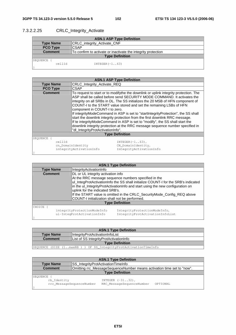
ETSI
ETSI TS 134 123-3 V5.5.0 (2006-06) 1023GPP TS 34.123-3 version 5.5.0 Release 5
7.3.2.2.25 CRLC_Integrity_Activate
ASN.1 ASP Type Definition Type Name CRLC_integrity_Activate_CNF PCO Type CSAP Comment To confirm to activate or inactivate the integrity protection
Type Definition SEQUENCE { cellId INTEGER(-1..63) }
ASN.1 ASP Type Definition Type Name CRLC_Integrity_Activate_REQ PCO Type CSAP Comment To request to start or to modifythe the downlink or uplink integrity protection. The
ASP shall be called before send SECURITY MODE COMMAND. It activates the integrity on all SRBs in DL. The SS initializes the 20 MSB of HFN component of COUNT-I to the START value stored and set the remaining LSBs of HFN component in COUNT-I to zero. If integrityModeCommand in ASP is set to "startIntegrityProtection", the SS shall start the downlink integrity protection from the first downlink RRC message. If te integrityModeCommand in ASP is set to "modify", the SS shall start the downlink integrity protection at the RRC message sequence number specified in "dl_IntegrityProtActivationInfo".
Type Definition SEQUENCE { cellId INTEGER(-1..63), cn_DomainIdentity CN_DomainIdentity, integrityActivationInfo IntegrityActivationInfo }
ASN.1 Type Definition Type Name IntegrityActivationInfo Comment DL or UL integrity activation info
At the RRC message sequence numbers specified in the ul_IntegProtActivationInfo the SS shall initialize COUNT-I for the SRB's indicated in the ul_IntegrityProtActivationInfo and start using the new configuration on uplink for the indicated SRB's. If the START value is omitted in the CRLC_SecurityMode_Config_REQ above COUNT-I initialization shall not be performed.
Type Definition CHOICE { integrityProtectionModeInfo IntegrityProtectionModeInfo, ul-IntegProtActivationInfo IntegrityProtActivationInfoList }
ASN.1 Type Definition Type Name IntegrityProtActivationInfoList Comment List of SS IntegrityProtActivationInfo
Type Definition SEQUENCE (SIZE (1..maxRB ) ) OF SS_IntegrityProtActivationTimeInfo
ASN.1 Type Definition Type Name SS_IntegrityProtActivationTimeInfo Comment Omitting rrc_MessageSequenceNumber means activation time set to "now".
Type Definition SEQUENCE { rb_Identity INTEGER (-31..32), rrc_MessageSequenceNumber RRC_MessageSequenceNumber OPTIONAL }
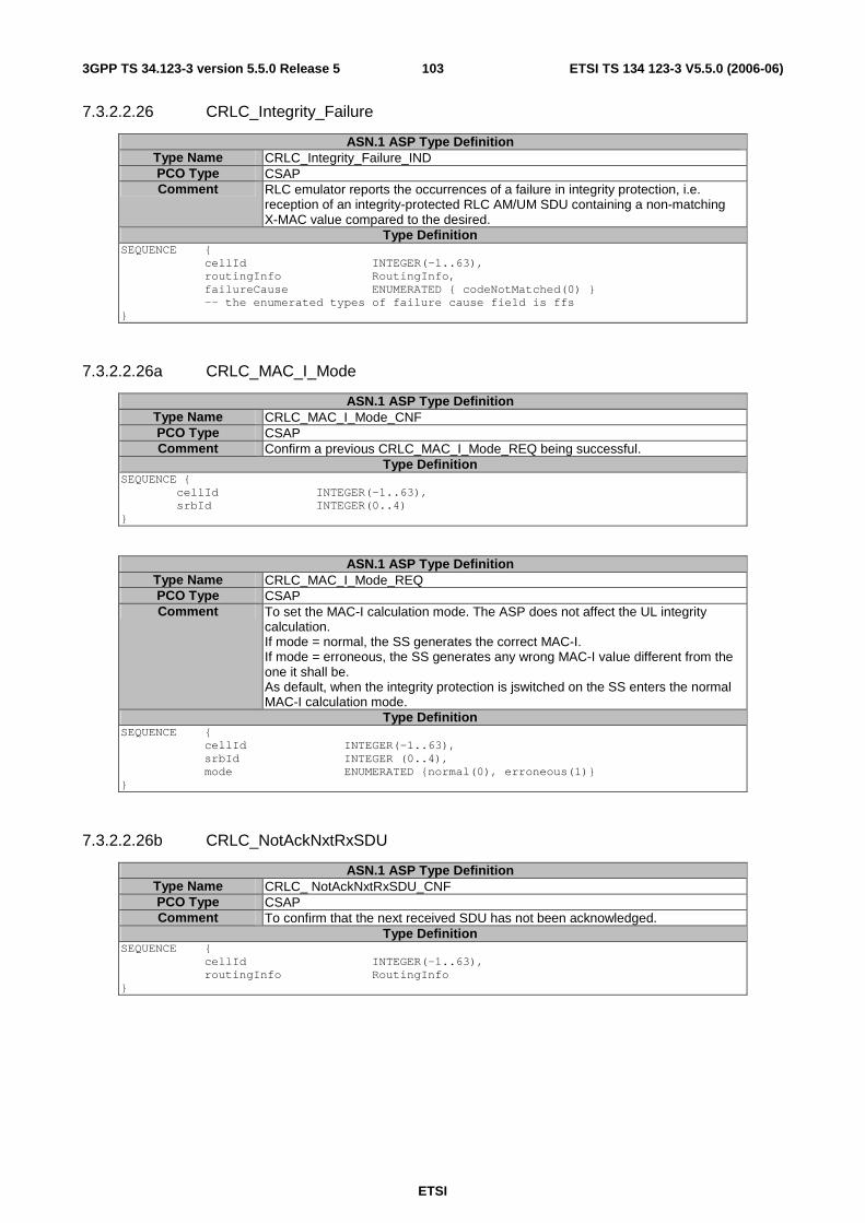
ETSI
ETSI TS 134 123-3 V5.5.0 (2006-06) 1033GPP TS 34.123-3 version 5.5.0 Release 5
7.3.2.2.26 CRLC_Integrity_Failure
ASN.1 ASP Type Definition Type Name CRLC_Integrity_Failure_IND PCO Type CSAP Comment RLC emulator reports the occurrences of a failure in integrity protection, i.e.
reception of an integrity-protected RLC AM/UM SDU containing a non-matching X-MAC value compared to the desired.
Type Definition SEQUENCE { cellId INTEGER(-1..63), routingInfo RoutingInfo, failureCause ENUMERATED { codeNotMatched(0) } -- the enumerated types of failure cause field is ffs }
7.3.2.2.26a CRLC_MAC_I_Mode
ASN.1 ASP Type Definition Type Name CRLC_MAC_I_Mode_CNF PCO Type CSAP Comment Confirm a previous CRLC_MAC_I_Mode_REQ being successful.
Type Definition SEQUENCE { cellId INTEGER(-1..63), srbId INTEGER(0..4) }
ASN.1 ASP Type Definition Type Name CRLC_MAC_I_Mode_REQ PCO Type CSAP Comment To set the MAC-I calculation mode. The ASP does not affect the UL integrity
calculation. If mode = normal, the SS generates the correct MAC-I. If mode = erroneous, the SS generates any wrong MAC-I value different from the one it shall be. As default, when the integrity protection is jswitched on the SS enters the normal MAC-I calculation mode.
Type Definition SEQUENCE { cellId INTEGER(-1..63), srbId INTEGER (0..4), mode ENUMERATED {normal(0), erroneous(1)} }
7.3.2.2.26b CRLC_NotAckNxtRxSDU
ASN.1 ASP Type Definition Type Name CRLC_ NotAckNxtRxSDU_CNF PCO Type CSAP Comment To confirm that the next received SDU has not been acknowledged.
Type Definition SEQUENCE { cellId INTEGER(-1..63), routingInfo RoutingInfo }
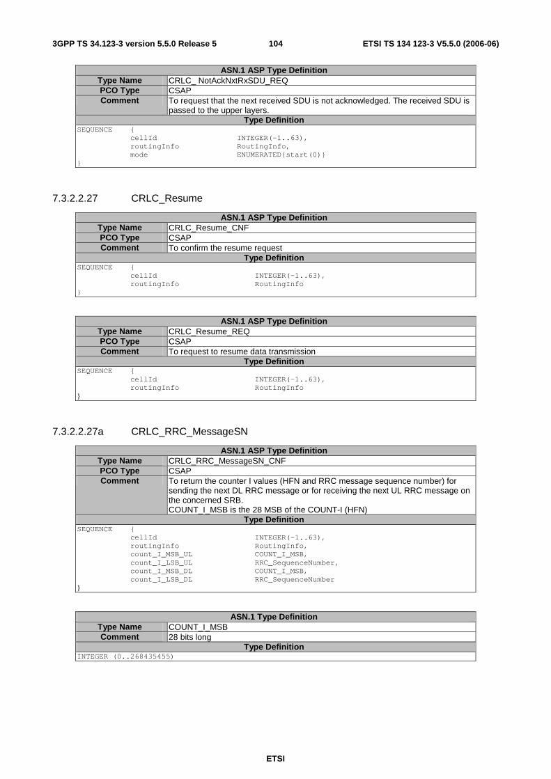
ETSI
ETSI TS 134 123-3 V5.5.0 (2006-06) 1043GPP TS 34.123-3 version 5.5.0 Release 5
ASN.1 ASP Type Definition Type Name CRLC_ NotAckNxtRxSDU_REQ PCO Type CSAP Comment To request that the next received SDU is not acknowledged. The received SDU is
passed to the upper layers. Type Definition
SEQUENCE { cellId INTEGER(-1..63), routingInfo RoutingInfo, mode ENUMERATED{start(0)} }
7.3.2.2.27 CRLC_Resume
ASN.1 ASP Type Definition Type Name CRLC_Resume_CNF PCO Type CSAP Comment To confirm the resume request
Type Definition SEQUENCE { cellId INTEGER(-1..63), routingInfo RoutingInfo }
ASN.1 ASP Type Definition Type Name CRLC_Resume_REQ PCO Type CSAP Comment To request to resume data transmission
Type Definition SEQUENCE { cellId INTEGER(-1..63), routingInfo RoutingInfo }
7.3.2.2.27a CRLC_RRC_MessageSN
ASN.1 ASP Type Definition Type Name CRLC_RRC_MessageSN_CNF PCO Type CSAP Comment To return the counter I values (HFN and RRC message sequence number) for
sending the next DL RRC message or for receiving the next UL RRC message on the concerned SRB. COUNT_I_MSB is the 28 MSB of the COUNT-I (HFN)
Type Definition SEQUENCE { cellId INTEGER(-1..63), routingInfo RoutingInfo, count_I_MSB_UL COUNT_I_MSB, count_I_LSB_UL RRC_SequenceNumber, count_I_MSB_DL COUNT_I_MSB, count_I_LSB_DL RRC_SequenceNumber }
ASN.1 Type Definition Type Name COUNT_I_MSB Comment 28 bits long
Type Definition INTEGER (0..268435455)

ETSI
ETSI TS 134 123-3 V5.5.0 (2006-06) 1053GPP TS 34.123-3 version 5.5.0 Release 5
ASN.1 Type Definition Type Name RRC_SequenceNumber Comment 4 bits long
Type Definition INTEGER (0..15)
ASN.1 ASP Type Definition Type Name CRLC_RRC_MessageSN_REQ PCO Type CSAP Comment To request the SS to return the values in COUNT-I for sending the next DL RRC
message or for receiving the next UL RRC message on the concerned SRB. Type Definition
SEQUENCE { cellId INTEGER(-1..63), routingInfo RoutingInfo }
7.3.2.2.28 CRLC_SecurityMode_Config
ASN.1 ASP Type Definition Type Name CRLC_SecurityMode_Config_CNF PCO Type CSAP Comment To confirm to configure the RLC security mode
If several subsequent CRLC_Integrity_Activate_REQ or CRLC_Ciphering_Activate_REQ follow this ASP, the SS shall take a serial of specified actions on the same contents in this ASP at the activation time indicated in each CRLC_ Integrity (or Ciphering)_Activate_REQ.
Type Definition SEQUENCE { cellId INTEGER(-1..63) }
ASN.1 ASP Type Definition Type Name CRLC_SecurityMode_Config_REQ PCO Type CSAP Comment To request to configure the RLC security mode
Type Definition SEQUENCE { cellId INTEGER(-1..63), rlcSecurityInfo SecurityInfo}
ASN.1 Type Definition Type Name SecurityInfo Comment The integrityKey is not applicable to MAC
Type Definition SEQUENCE{ cn-DomainIdentity CN-DomainIdentity, startValue START_VALUE OPTIONAL, cipheringKey BITSTRING(128) OPTIONAL, integrityKey BITSTRING(128) OPTIONAL, gsmCipheringKey BITSTRING(64) OPTIONAL }
Detailed Comments
When the SS receives SecurityInfo, the SS first stores the contents. The SecurityInfo contents is not activated until receiving the subsequent ASP, CRLC_Ciphering_Activate_REQ, CMAC_Ciphering_Activate_REQ or CRLC_Integrity_Activate_REQ. Omitted fields of SecurityInfo shall not be affected by the subsequent ASP at the activation time. EXAMPLE: Omitting of startValue indicates not to re-initialize the relevant COUNT-C or COUNT-I, omitting of cipheringKey indicates that the current ciphering key is valid.

ETSI
ETSI TS 134 123-3 V5.5.0 (2006-06) 1063GPP TS 34.123-3 version 5.5.0 Release 5
7.3.2.2.28a CRLC_SetRRC_MessageSN
ASN.1 ASP Type Definition Type Name CRLC_SetRRC_MessageSN_CNF PCO Type CSAP Comment To confirm the RRC message sequence number setting request
Type Definition SEQUENCE { cellId INTEGER(-1..63), routingInfo RoutingInfo }
ASN.1 ASP Type Definition Type Name CRLC_SetRRC_MessageSN_REQ PCO Type CSAP Comment To request the SS to set the RRC message sequence number in COUNT-I to the
value specified in this ASP. The ASP is used to initialize SS RRC SN. Type Definition
SEQUENCE { cellId INTEGER(-1..63), routingInfo RoutingInfo, count_I_LSB_UL RRC_SequenceNumber OPTIONAL, count_I_LSB_DL RRC_SequenceNumber OPTIONAL }
7.3.2.2.28b CRLC_Set_Count_I
ASN.1 ASP Type Definition Type Name CRLC_Set_Count_I_CNF PCO Type CSAP Comment To confirm the count_I_MSB and the RRC message sequence number setting
request Type Definition
SEQUENCE { cellId INTEGER(-1..63), routingInfo RoutingInfo }
ASN.1 ASP Type Definition Type Name CRLC_Set_Count_I_REQ PCO Type CSAP Comment To request the SS to set the 28 MSB and 4 LSB (RRC message sequence
number) in COUNT-I according to the parameter values specified in this ASP. Parameters omitted in this ASP shall leave the corresponding bits in the SS COUNT-I unchanged. Typically the parameters count_I_MSB_UL and count_I_MSB_DL are omitted. They are only applied in a few specific security test cases requiring restoration of the used integrity context. Note: The 28 MSBs are initialized with the UE-provided START value plus 8 bits set to 0, using a different ASP (CRLC_SecurityMode_Config_REQ).
Type Definition SEQUENCE { cellId INTEGER(-1..63), routingInfo RoutingInfo, count_I_LSB_UL RRC_SequenceNumber OPTIONAL, count_I_LSB_DL RRC_SequenceNumber OPTIONAL, count_I_MSB_UL COUNT_I_MSB OPTIONAL, count_I_MSB_DL COUNT_I_MSB OPTIONAL }
.
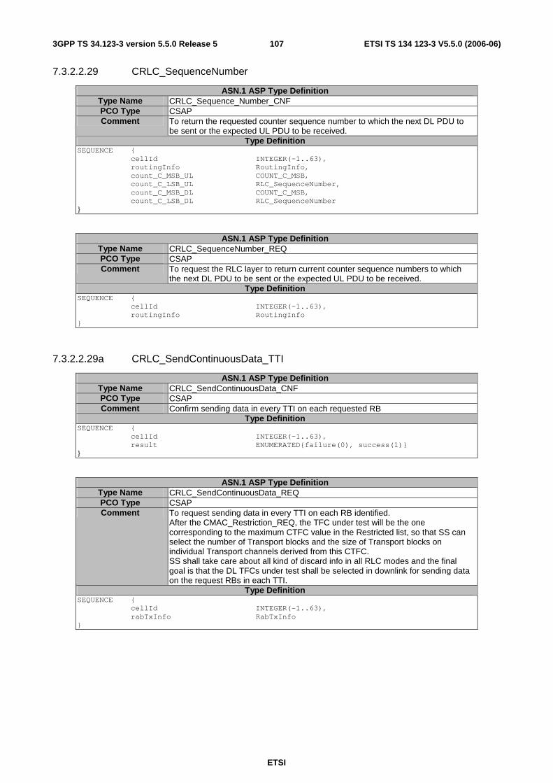
ETSI
ETSI TS 134 123-3 V5.5.0 (2006-06) 1073GPP TS 34.123-3 version 5.5.0 Release 5
7.3.2.2.29 CRLC_SequenceNumber
ASN.1 ASP Type Definition Type Name CRLC_Sequence_Number_CNF PCO Type CSAP Comment To return the requested counter sequence number to which the next DL PDU to
be sent or the expected UL PDU to be received. Type Definition
SEQUENCE { cellId INTEGER(-1..63), routingInfo RoutingInfo, count_C_MSB_UL COUNT_C_MSB, count_C_LSB_UL RLC_SequenceNumber, count_C_MSB_DL COUNT_C_MSB, count_C_LSB_DL RLC_SequenceNumber }
ASN.1 ASP Type Definition Type Name CRLC_SequenceNumber_REQ PCO Type CSAP Comment To request the RLC layer to return current counter sequence numbers to which
the next DL PDU to be sent or the expected UL PDU to be received. Type Definition
SEQUENCE { cellId INTEGER(-1..63), routingInfo RoutingInfo }
7.3.2.2.29a CRLC_SendContinuousData_TTI
ASN.1 ASP Type Definition Type Name CRLC_SendContinuousData_CNF PCO Type CSAP Comment Confirm sending data in every TTI on each requested RB
Type Definition SEQUENCE { cellId INTEGER(-1..63), result ENUMERATED{failure(0), success(1)} }
ASN.1 ASP Type Definition Type Name CRLC_SendContinuousData_REQ PCO Type CSAP Comment To request sending data in every TTI on each RB identified.
After the CMAC_Restriction_REQ, the TFC under test will be the one corresponding to the maximum CTFC value in the Restricted list, so that SS can select the number of Transport blocks and the size of Transport blocks on individual Transport channels derived from this CTFC. SS shall take care about all kind of discard info in all RLC modes and the final goal is that the DL TFCs under test shall be selected in downlink for sending data on the request RBs in each TTI.
Type Definition SEQUENCE { cellId INTEGER(-1..63), rabTxInfo RabTxInfo }
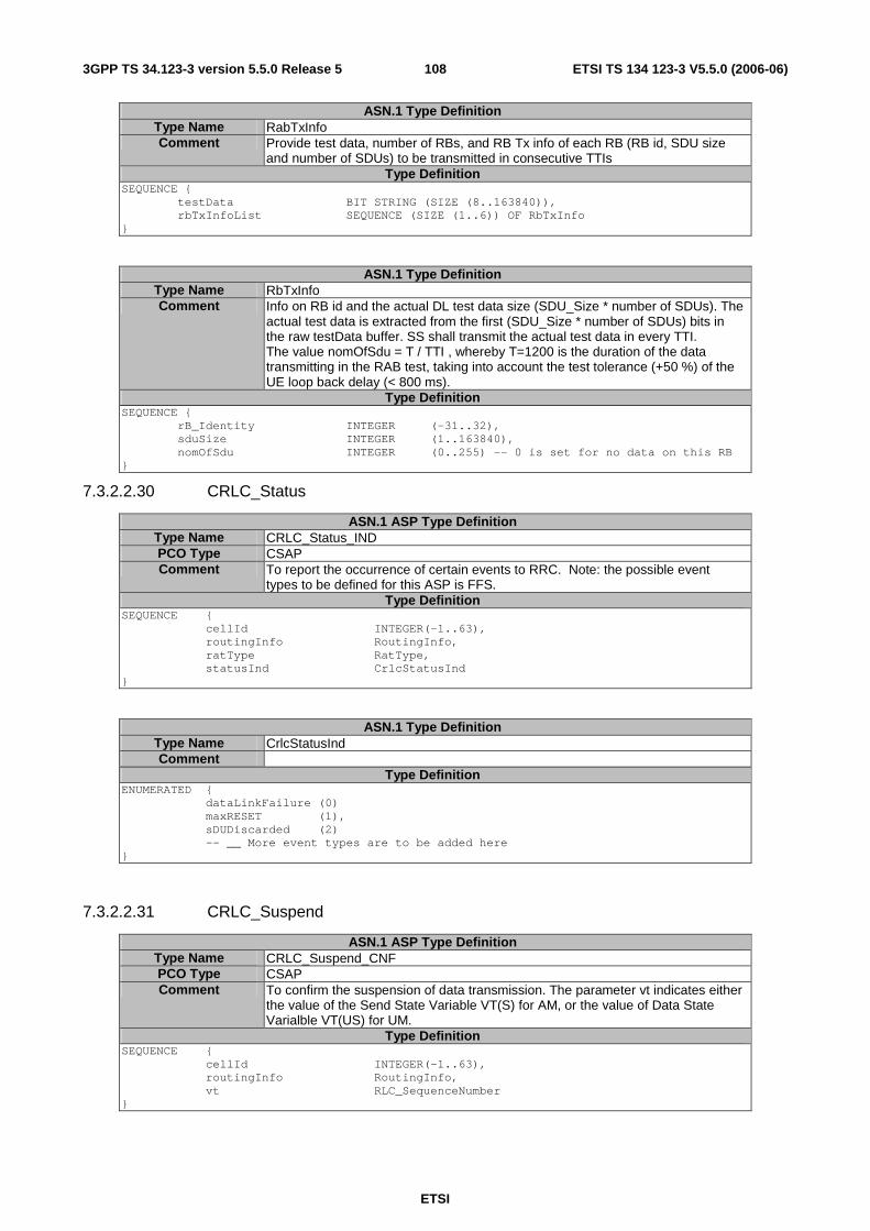
ETSI
ETSI TS 134 123-3 V5.5.0 (2006-06) 1083GPP TS 34.123-3 version 5.5.0 Release 5
ASN.1 Type Definition Type Name RabTxInfo Comment Provide test data, number of RBs, and RB Tx info of each RB (RB id, SDU size
and number of SDUs) to be transmitted in consecutive TTIs Type Definition
SEQUENCE { testData BIT STRING (SIZE (8..163840)), rbTxInfoList SEQUENCE (SIZE (1..6)) OF RbTxInfo }
ASN.1 Type Definition Type Name RbTxInfo Comment Info on RB id and the actual DL test data size (SDU_Size * number of SDUs). The
actual test data is extracted from the first (SDU_Size * number of SDUs) bits in the raw testData buffer. SS shall transmit the actual test data in every TTI. The value nomOfSdu = T / TTI , whereby T=1200 is the duration of the data transmitting in the RAB test, taking into account the test tolerance (+50 %) of the UE loop back delay (< 800 ms).
Type Definition SEQUENCE { rB_Identity INTEGER (-31..32), sduSize INTEGER (1..163840), nomOfSdu INTEGER (0..255) -- 0 is set for no data on this RB }
7.3.2.2.30 CRLC_Status
ASN.1 ASP Type Definition Type Name CRLC_Status_IND PCO Type CSAP Comment To report the occurrence of certain events to RRC. Note: the possible event
types to be defined for this ASP is FFS. Type Definition
SEQUENCE { cellId INTEGER(-1..63), routingInfo RoutingInfo, ratType RatType, statusInd CrlcStatusInd }
ASN.1 Type Definition Type Name CrlcStatusInd Comment
Type Definition ENUMERATED { dataLinkFailure (0) maxRESET (1), sDUDiscarded (2) -- __ More event types are to be added here }
7.3.2.2.31 CRLC_Suspend
ASN.1 ASP Type Definition Type Name CRLC_Suspend_CNF PCO Type CSAP Comment To confirm the suspension of data transmission. The parameter vt indicates either
the value of the Send State Variable VT(S) for AM, or the value of Data State Varialble VT(US) for UM.
Type Definition SEQUENCE { cellId INTEGER(-1..63), routingInfo RoutingInfo, vt RLC_SequenceNumber }
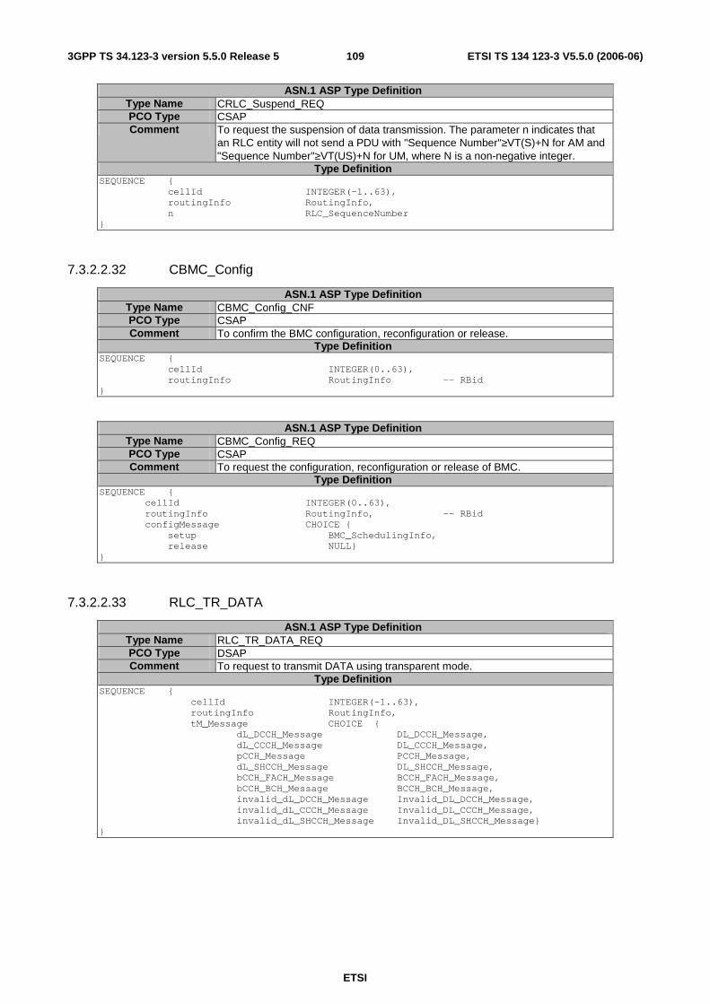
ETSI
ETSI TS 134 123-3 V5.5.0 (2006-06) 1093GPP TS 34.123-3 version 5.5.0 Release 5
ASN.1 ASP Type Definition Type Name CRLC_Suspend_REQ PCO Type CSAP Comment To request the suspension of data transmission. The parameter n indicates that
an RLC entity will not send a PDU with "Sequence Number"≥VT(S)+N for AM and "Sequence Number"≥VT(US)+N for UM, where N is a non-negative integer.
Type Definition SEQUENCE { cellId INTEGER(-1..63), routingInfo RoutingInfo, n RLC_SequenceNumber }
7.3.2.2.32 CBMC_Config
ASN.1 ASP Type Definition Type Name CBMC_Config_CNF PCO Type CSAP Comment To confirm the BMC configuration, reconfiguration or release.
Type Definition SEQUENCE { cellId INTEGER(0..63), routingInfo RoutingInfo -- RBid }
ASN.1 ASP Type Definition Type Name CBMC_Config_REQ PCO Type CSAP Comment To request the configuration, reconfiguration or release of BMC.
Type Definition SEQUENCE { cellId INTEGER(0..63), routingInfo RoutingInfo, -- RBid configMessage CHOICE { setup BMC_SchedulingInfo, release NULL} }
7.3.2.2.33 RLC_TR_DATA
ASN.1 ASP Type Definition Type Name RLC_TR_DATA_REQ PCO Type DSAP Comment To request to transmit DATA using transparent mode.
Type Definition SEQUENCE { cellId INTEGER(-1..63), routingInfo RoutingInfo, tM_Message CHOICE { dL_DCCH_Message DL_DCCH_Message, dL_CCCH_Message DL_CCCH_Message, pCCH_Message PCCH_Message, dL_SHCCH_Message DL_SHCCH_Message, bCCH_FACH_Message BCCH_FACH_Message, bCCH_BCH_Message BCCH_BCH_Message, invalid_dL_DCCH_Message Invalid_DL_DCCH_Message, invalid_dL_CCCH_Message Invalid_DL_CCCH_Message, invalid_dL_SHCCH_Message Invalid_DL_SHCCH_Message} }
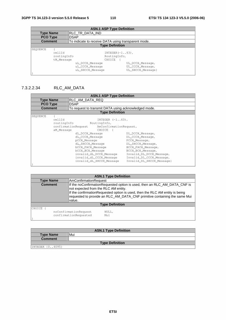
ETSI
ETSI TS 134 123-3 V5.5.0 (2006-06) 1103GPP TS 34.123-3 version 5.5.0 Release 5
ASN.1 ASP Type Definition Type Name RLC_TR_DATA_IND PCO Type DSAP Comment To indicate to receive DATA using transparent mode.
Type Definition SEQUENCE { cellId INTEGER(-1..63), routingInfo RoutingInfo, tM_Message CHOICE { uL_DCCH_Message UL_DCCH_Message, uL_CCCH_Message UL_CCCH_Message, uL_SHCCH_Message UL_SHCCH_Message} }
7.3.2.2.34 RLC_AM_DATA
ASN.1 ASP Type Definition Type Name RLC_AM_DATA_REQ PCO Type DSAP Comment To request to transmit DATA using acknowledged mode.
Type Definition SEQUENCE { cellId INTEGER (-1..63), routingInfo RoutingInfo, confirmationRequest AmConfirmationRequest, aM_Message CHOICE { dL_DCCH_Message DL_DCCH_Message, dL_CCCH_Message DL_CCCH_Message, pCCH_Message PCCH_Message, dL_SHCCH_Message DL_SHCCH_Message, bCCH_FACH_Message BCCH_FACH_Message, bCCH_BCH_Message BCCH_BCH_Message, invalid_dL_DCCH_Message Invalid_DL_DCCH_Message, invalid_dL_CCCH_Message Invalid_DL_CCCH_Message, invalid_dL_SHCCH_Message Invalid_DL_SHCCH_Message} }
ASN.1 Type Definition Type Name AmConfirmationRequest Comment If the noConfirmationRequested option is used, then an RLC_AM_DATA_CNF is
not expected from the RLC AM entity. If the confirmationRequested option is used, then the RLC AM entity is being requested to provide an RLC_AM_DATA_CNF primitive containing the same Mui value.
Type Definition CHOICE { noConfirmationRequest NULL, confirmationRequested Mui }
ASN.1 Type Definition Type Name Mui Comment
Type Definition INTEGER {0..4095}

ETSI
ETSI TS 134 123-3 V5.5.0 (2006-06) 1113GPP TS 34.123-3 version 5.5.0 Release 5
ASN.1 ASP Type Definition Type Name RLC_AM_DATA_IND PCO Type DSAP Comment To indicate to receive DATA using acknowledged mode.
Type Definition SEQUENCE { cellId INTEGER(-1..63), routingInfo RoutingInfo, integrityResult IntegrityResult, aM_Message CHOICE { uL_DCCH_Message UL_DCCH_Message, uL_CCCH_Message UL_CCCH_Message, uL_SHCCH_Message UL_SHCCH_Message} }
ASN.1 Type Definition Type Name IntegrityResult Comment
Type Definition CHOICE { integrityNotUsed NULL, integrityUsed IntegrityStatus }
ASN.1 Type Definition Type Name IntegrityStatus Comment
Type Definition ENUMERATED { i_pass(0), i_fail(1) }
ASN.1 ASP Type Definition Type Name RLC_AM_DATA_CNF PCO Type DSAP Comment For RLC emulator to report to the upper layer that a previously transmitted SDU
has been acknowledged correctly by the UE Type Definition
SEQUENCE { cellId INTEGER(-1..63), routingInfo RoutingInfo, mui Mui }
7.3.2.2.35 RLC_UM_DATA
ASN.1 ASP Type Definition Type Name RLC_UM_DATA_REQ PCO Type DSAP Comment To request to transmit DATA using unacknowledged mode.
Type Definition SEQUENCE { cellId INTEGER(-1..63), routingInfo RoutingInfo, uM_Message CHOICE { dL_DCCH_Message DL_DCCH_Message, dL_CCCH_Message DL_CCCH_Message, pCCH_Message PCCH_Message, dL_SHCCH_Message DL_SHCCH_Message, bCCH_FACH_Message BCCH_FACH_Message, bCCH_BCH_Message BCCH_BCH_Message, invalid_dL_DCCH_Message Invalid_DL_DCCH_Message, invalid_dL_CCCH_Message Invalid_DL_CCCH_Message, invalid_dL_SHCCH_Message Invalid_DL_SHCCH_Message}, specialLI BOOLEAN }

ETSI
ETSI TS 134 123-3 V5.5.0 (2006-06) 1123GPP TS 34.123-3 version 5.5.0 Release 5
ASN.1 ASP Type Definition Type Name RLC_UM_DATA_IND PCO Type DSAP Comment To indicate to receive DATA using unacknowledged mode.
Type Definition SEQUENCE { cellId INTEGER(-1..63), routingInfo RoutingInfo, integrityResult IntegrityResult, uM_Message CHOICE { uL_DCCH_Message UL_DCCH_Message, uL_CCCH_Message UL_CCCH_Message, uL_SHCCH_Message UL_SHCCH_Message} }
7.3.2.2.36 RLC_MACes_DATA_IND (Rel-6 or later)
ASN.1 ASP Type Definition Type Name RLC_MACes_DATA_IND PCO Type DSAP Comment This ASP is used for MACes delivering data in MAC_es testing.
The routingInfo is RB identity, corresponding to RLC in TM, (tsc_RB_DTCH_E_DCH_MAC0(-20), tsc_RB_DTCH_E_DCH_MAC1(-21), or tsc_RB_DTCH_E_DCH_MAC2(-22)). The cfn and subframe indicate the CFN and sub-frame number on which the mACesSDUs (RLC PDUs) were received. The ddi, tsn and n are the reported values in the header of each MAC-es PDU that carries the mACesSDUs.
Type Definition SEQUENCE { routingInfo RoutingInfo, cfn INTEGER (0..255), subframe INTEGER (0..4|7), -- Value 7 applied when TTI=2ms happyBit ENUMERATED {happy(0), unhappy(1)}, ddi INTEGER (0..62), tsn INTEGER (0..63), n INTEGER (0..63), mACesSDUs SEQUENCE (SIZE (1..63)) OF MACesSDU }
ASN.1 Type Definition Type Name MACesSDU Comment
Type Definition BIT STRING -- RLC PDU in TM
7.3.2.3 Specific ASP and IE definitions for 1.28 Mcps TDD (Rel-4 or later)
The ASP definitions in 7.3.2.2 are applied to 1.28 Mcps TDD with the exceptions.
1. The ASP definition CPHY_AICH_AckModeSet is not applied.
2. Specifici IE definitions in this clause replace the definitions in 7.3.2.2.
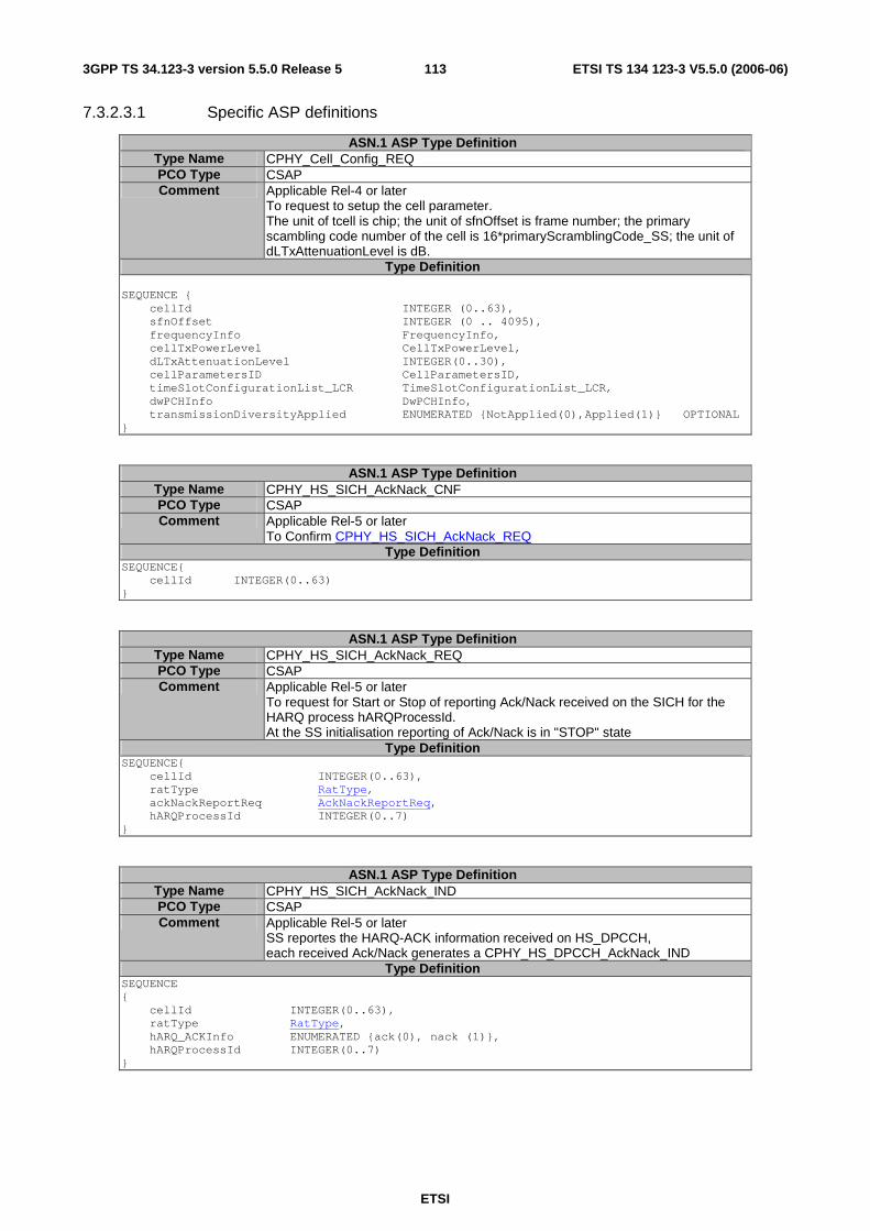
ETSI
ETSI TS 134 123-3 V5.5.0 (2006-06) 1133GPP TS 34.123-3 version 5.5.0 Release 5
7.3.2.3.1 Specific ASP definitions
ASN.1 ASP Type Definition Type Name CPHY_Cell_Config_REQ PCO Type CSAP Comment Applicable Rel-4 or later
To request to setup the cell parameter. The unit of tcell is chip; the unit of sfnOffset is frame number; the primary scambling code number of the cell is 16*primaryScramblingCode_SS; the unit of dLTxAttenuationLevel is dB.
Type Definition SEQUENCE { cellId INTEGER (0..63), sfnOffset INTEGER (0 .. 4095), frequencyInfo FrequencyInfo, cellTxPowerLevel CellTxPowerLevel, dLTxAttenuationLevel INTEGER(0..30), cellParametersID CellParametersID, timeSlotConfigurationList_LCR TimeSlotConfigurationList_LCR, dwPCHInfo DwPCHInfo, transmissionDiversityApplied ENUMERATED {NotApplied(0),Applied(1)} OPTIONAL }
ASN.1 ASP Type Definition Type Name CPHY_HS_SICH_AckNack_CNF PCO Type CSAP Comment Applicable Rel-5 or later
To Confirm CPHY_HS_SICH_AckNack_REQ Type Definition
SEQUENCE{ cellId INTEGER(0..63) }
ASN.1 ASP Type Definition Type Name CPHY_HS_SICH_AckNack_REQ PCO Type CSAP Comment Applicable Rel-5 or later
To request for Start or Stop of reporting Ack/Nack received on the SICH for the HARQ process hARQProcessId. At the SS initialisation reporting of Ack/Nack is in "STOP" state
Type Definition SEQUENCE{ cellId INTEGER(0..63), ratType RatType, ackNackReportReq AckNackReportReq, hARQProcessId INTEGER(0..7) }
ASN.1 ASP Type Definition Type Name CPHY_HS_SICH_AckNack_IND PCO Type CSAP Comment Applicable Rel-5 or later
SS reportes the HARQ-ACK information received on HS_DPCCH, each received Ack/Nack generates a CPHY_HS_DPCCH_AckNack_IND �
Type Definition SEQUENCE { cellId INTEGER(0..63), ratType RatType, hARQ_ACKInfo ENUMERATED {ack(0), nack (1)}, hARQProcessId INTEGER(0..7) }
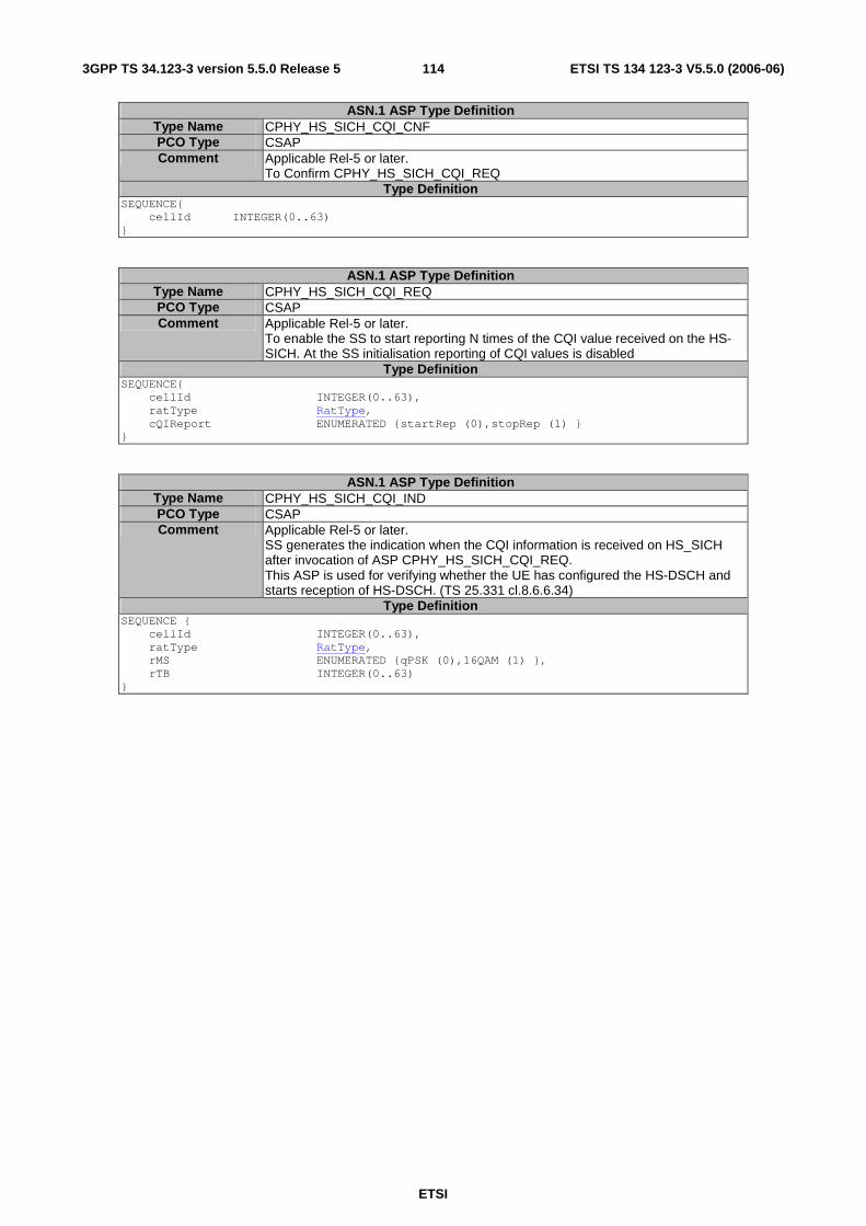
ETSI
ETSI TS 134 123-3 V5.5.0 (2006-06) 1143GPP TS 34.123-3 version 5.5.0 Release 5
ASN.1 ASP Type Definition Type Name CPHY_HS_SICH_CQI_CNF PCO Type CSAP Comment Applicable Rel-5 or later.
To Confirm CPHY_HS_SICH_CQI_REQ Type Definition
SEQUENCE{ cellId INTEGER(0..63) } �
ASN.1 ASP Type Definition Type Name CPHY_HS_SICH_CQI_REQ PCO Type CSAP Comment Applicable Rel-5 or later.
To enable the SS to start reporting N times of the CQI value received on the HS-SICH. At the SS initialisation reporting of CQI values is disabled
Type Definition SEQUENCE{ cellId INTEGER(0..63), ratType RatType, cQIReport ENUMERATED {startRep (0),stopRep (1) } }
ASN.1 ASP Type Definition Type Name CPHY_HS_SICH_CQI_IND PCO Type CSAP Comment Applicable Rel-5 or later.
SS generates the indication when the CQI information is received on HS_SICH after invocation of ASP CPHY_HS_SICH_CQI_REQ. This ASP is used for verifying whether the UE has configured the HS-DSCH and starts reception of HS-DSCH. (TS 25.331 cl.8.6.6.34) �
Type Definition SEQUENCE { cellId INTEGER(0..63), ratType RatType, rMS ENUMERATED {qPSK (0),16QAM (1) }, rTB INTEGER(0..63) }

ETSI
ETSI TS 134 123-3 V5.5.0 (2006-06) 1153GPP TS 34.123-3 version 5.5.0 Release 5
Type Name CMAC_MAChs_TFRCconfigure_REQ PCO Type CSAP Comment Applicable Rel-5 or later
To configure the TFRC selection in the MAC-hs entity If explicitlyConfigured is selected in tfrcConfigMode, the SS shall use all the parameter values specified to configure a correct transport format and radio resources. If sS_Configured is selected, the parameter value range is specified. SS shall dynamically select the suitable values for the parameters'modulationScheme', 'dLTimeslotandCode', 'noOfChannelisatonCodes ', tbSizeIndexOnHS_SCCH', 'redundancyVersion' and 'hs_PDSCH_TxPower' according to UE's capability category and CQI information reported by the UE. MaxnoofDLtsLCR=6
Type Definition SEQUENCE { cellId INTEGER(-1..63), tfrcConfigMode CHOICE { explicitlyConfigured SEQUENCE { modulationScheme ModulationScheme, noOfTimeSlots INTEGER (0..6), noOfCodesPerTimeslot INTEGER (0..16), tbSizeIndexOnHS_SCCH INTEGER (0..63), redundancyVersion INTEGER (0..7), hs_PDSCH_TxPower DL_TxPower -- default offset related -- to p-PCCPCH sS_Configured SEQUENCE { numofTimeslots INTEGER (0..6), numofCodesPerTimeslot INTEGER (0..16), iniHS_PDSCH_TxPower DL_TxPower -- default offset related -- to p-PCCPCH }
} }
7.3.2.3.2 Specific IE definitions
ASN.1 Type Definition Type Name CphyRlModifyReq Comment Applicable Rel-4 or later for LCR TDD
Type Definition SEQUENCE { activationTime SS_ActivationTime, physicalChannelInfo CHOICE { secondaryCCPCHInfo SecondaryCCPCHInfo, pRACHInfo PRACHInfo, dPCHInfo DPCHInfo, dPCHInfo_r5 DPCHInfo_r5, hS_DPSCHInfo HS_DPSCHInfo }, trchConfigToFollow BOOLEAN DEFAULT TRUE }
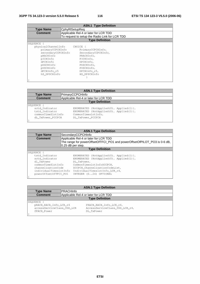
ETSI
ETSI TS 134 123-3 V5.5.0 (2006-06) 1163GPP TS 34.123-3 version 5.5.0 Release 5
ASN.1 Type Definition Type Name CphyRlSetupReq Comment Applicable Rel-4 or later for LCR TDD
To request to setup the Radio Link for LCR TDD Type Definition
SEQUENCE { physicalChannelInfo CHOICE { primaryCCPCHInfo PrimaryCCPCHInfo, secondaryCCPCHInfo SecondaryCCPCHInfo, pRACHInfo PRACHInfo, pICHInfo PICHInfo, dPCHInfo DPCHInfo, pDSCHInfo PDSCHInfo, pUSCHInfo PUSCHInfo, dPCHInfo_r5 DPCHInfo_r5, hS_DPSCHInfo HS_DPSCHInfo } }
ASN.1 Type Definition Type Name PrimaryCCPCHInfo Comment Applicable Rel-4 or later for LCR TDD
Type Definition SEQUENCE { sctd_Indicator ENUMERATED {NotApplied(0), Applied(1)}, tstd_Indicator ENUMERATED {NotApplied(0), Applied(1)}, commonTimeSlotInfo CommonTimeslotInfo, dL_TxPower_PCCPCH DL_TxPower_PCCPCH }
ASN.1 Type Definition Type Name SecondaryCCPCHInfo Comment Applicable Rel-4 or later for LCR TDD
The range for powerOffsetOfTFCI_PO1 and powerOffsetOfPILOT_PO3 is 0-6 dB, 0.25 dB per step.
Type Definition SEQUENCE { tstd_Indicator ENUMERATED {NotApplied(0), Applied(1)}, sctd_Indicator ENUMERATED {NotApplied(0), Applied(1)}, dl_TxPower DL_TxPower, commonTimeSlotInfo CommonTimeslotInfoSCCPCH, channelisationCode SCCPCH_ChannelisationCodeList, individualTimeslotInfo IndividualTimeslotInfo_LCR_r4, powerOffsetOfTFCI_PO1 INTEGER (0..24) OPTIONAL }
ASN.1 Type Definition Type Name PRACHInfo Comment Applicable Rel-4 or later for LCR TDD
Type Definition SEQUENCE { pRACH_RACH_Info_LCR_r4 PRACH_RACH_Info_LCR_r4, accessServiceClass_TDD_LCR AccessServiceClass_TDD_LCR_r4, fPACH_Power DL_TxPower }
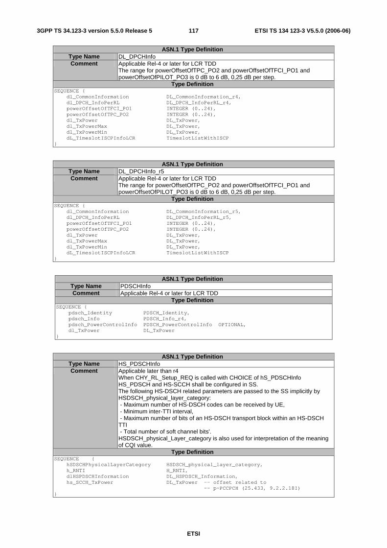
ETSI
ETSI TS 134 123-3 V5.5.0 (2006-06) 1173GPP TS 34.123-3 version 5.5.0 Release 5
ASN.1 Type Definition Type Name DL_DPCHInfo Comment Applicable Rel-4 or later for LCR TDD
The range for powerOffsetOfTPC_PO2 and powerOffsetOfTFCI_PO1 and powerOffsetOfPILOT_PO3 is 0 dB to 6 dB, 0,25 dB per step.
Type Definition SEQUENCE { dl_CommonInformation DL_CommonInformation_r4, dl_DPCH_InfoPerRL DL_DPCH_InfoPerRL_r4, powerOffsetOfTFCI_PO1 INTEGER (0..24), powerOffsetOfTPC_PO2 INTEGER (0..24), dl_TxPower DL_TxPower, dl_TxPowerMax DL_TxPower, dl_TxPowerMin DL_TxPower, dL_TimeslotISCPInfoLCR TimeslotListWithISCP }
ASN.1 Type Definition Type Name DL_DPCHInfo_r5 Comment Applicable Rel-4 or later for LCR TDD
The range for powerOffsetOfTPC_PO2 and powerOffsetOfTFCI_PO1 and powerOffsetOfPILOT_PO3 is 0 dB to 6 dB, 0,25 dB per step.
Type Definition SEQUENCE { dl_CommonInformation DL_CommonInformation_r5, dl_DPCH_InfoPerRL DL_DPCH_InfoPerRL_r5, powerOffsetOfTFCI_PO1 INTEGER (0..24), powerOffsetOfTPC_PO2 INTEGER (0..24), dl_TxPower DL_TxPower, dl_TxPowerMax DL_TxPower, dl_TxPowerMin DL_TxPower, dL_TimeslotISCPInfoLCR TimeslotListWithISCP }
ASN.1 Type Definition Type Name PDSCHInfo Comment Applicable Rel-4 or later for LCR TDD
Type Definition SEQUENCE { pdsch_Identity PDSCH_Identity, pdsch_Info PDSCH_Info_r4, pdsch_PowerControlInfo PDSCH_PowerControlInfo OPTIONAL, dl_TxPower DL_TxPower }
ASN.1 Type Definition Type Name HS_PDSCHInfo Comment Applicable later than r4
When CHY_RL_Setup_REQ is called with CHOICE of hS_PDSCHInfo HS_PDSCH and HS-SCCH shall be configured in SS. The following HS-DSCH related parameters are passed to the SS implicitly by HSDSCH_physical_layer_category: - Maximum number of HS-DSCH codes can be received by UE, - Minimum inter-TTI interval, - Maximum number of bits of an HS-DSCH transport block within an HS-DSCH TTI - Total number of soft channel bits'. HSDSCH_physical_Layer_category is also used for interpretation of the meaning of CQI value.
Type Definition SEQUENCE { hSDSCHPhysicalLayerCategory HSDSCH_physical_layer_category, h_RNTI H_RNTI, dlHSPDSCHInformation DL_HSPDSCH_Information, hs_SCCH_TxPower DL_TxPower -- offset related to -- p-PCCPCH (25.433, 9.2.2.18I) }
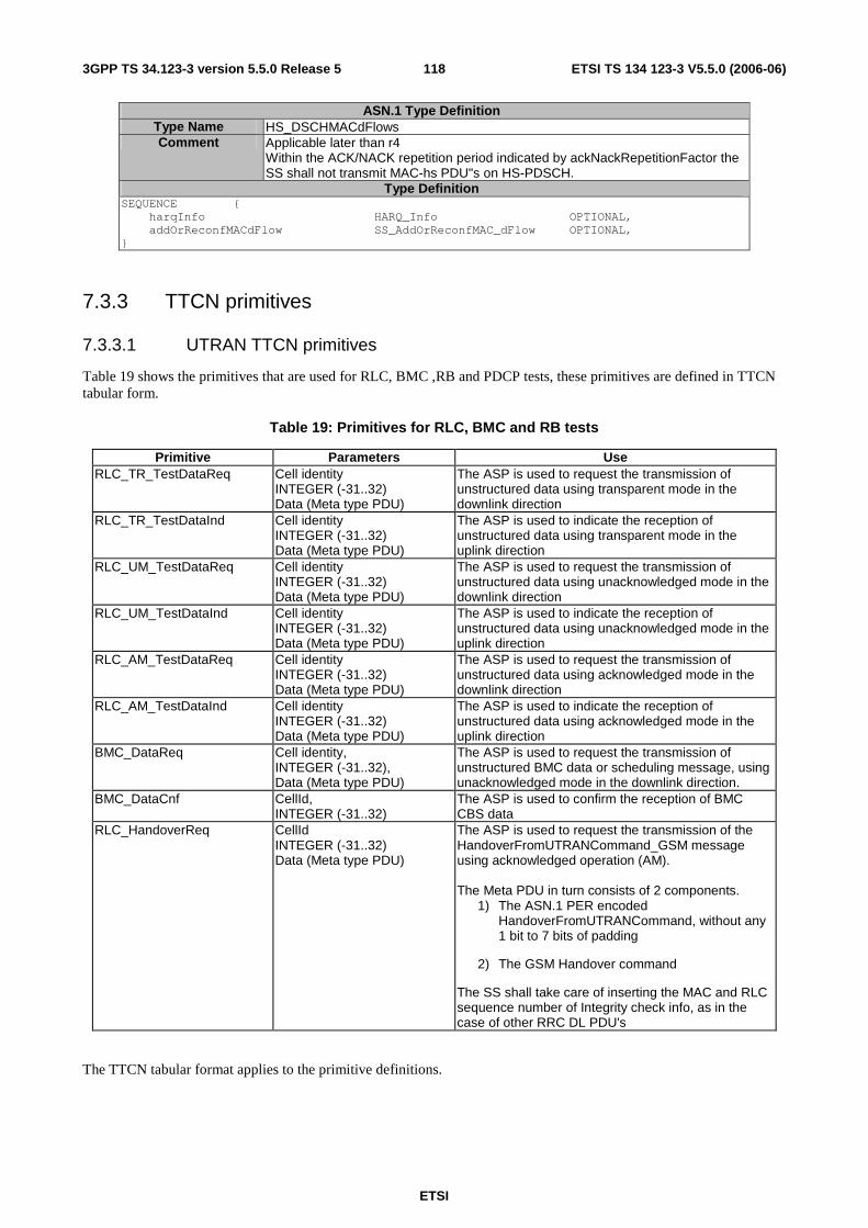
ETSI
ETSI TS 134 123-3 V5.5.0 (2006-06) 1183GPP TS 34.123-3 version 5.5.0 Release 5
ASN.1 Type Definition Type Name HS_DSCHMACdFlows Comment Applicable later than r4
Within the ACK/NACK repetition period indicated by ackNackRepetitionFactor the SS shall not transmit MAC-hs PDU"s on HS-PDSCH.
Type Definition SEQUENCE { harqInfo HARQ_Info OPTIONAL, addOrReconfMACdFlow SS_AddOrReconfMAC_dFlow OPTIONAL, }
7.3.3 TTCN primitives
7.3.3.1 UTRAN TTCN primitives
Table 19 shows the primitives that are used for RLC, BMC ,RB and PDCP tests, these primitives are defined in TTCN tabular form.
Table 19: Primitives for RLC, BMC and RB tests
Primitive Parameters Use RLC_TR_TestDataReq Cell identity
INTEGER (-31..32) Data (Meta type PDU)
The ASP is used to request the transmission of unstructured data using transparent mode in the downlink direction
RLC_TR_TestDataInd Cell identity INTEGER (-31..32) Data (Meta type PDU)
The ASP is used to indicate the reception of unstructured data using transparent mode in the uplink direction
RLC_UM_TestDataReq Cell identity INTEGER (-31..32) Data (Meta type PDU)
The ASP is used to request the transmission of unstructured data using unacknowledged mode in the downlink direction
RLC_UM_TestDataInd Cell identity INTEGER (-31..32) Data (Meta type PDU)
The ASP is used to indicate the reception of unstructured data using unacknowledged mode in the uplink direction
RLC_AM_TestDataReq Cell identity INTEGER (-31..32) Data (Meta type PDU)
The ASP is used to request the transmission of unstructured data using acknowledged mode in the downlink direction
RLC_AM_TestDataInd Cell identity INTEGER (-31..32) Data (Meta type PDU)
The ASP is used to indicate the reception of unstructured data using acknowledged mode in the uplink direction
BMC_DataReq Cell identity, INTEGER (-31..32), Data (Meta type PDU)
The ASP is used to request the transmission of unstructured BMC data or scheduling message, using unacknowledged mode in the downlink direction.
BMC_DataCnf CellId, INTEGER (-31..32)
The ASP is used to confirm the reception of BMC CBS data
RLC_HandoverReq CellId INTEGER (-31..32) Data (Meta type PDU)
The ASP is used to request the transmission of the HandoverFromUTRANCommand_GSM message using acknowledged operation (AM). The Meta PDU in turn consists of 2 components.
1) The ASN.1 PER encoded HandoverFromUTRANCommand, without any 1 bit to 7 bits of padding
2) The GSM Handover command
The SS shall take care of inserting the MAC and RLC sequence number of Integrity check info, as in the case of other RRC DL PDU's
The TTCN tabular format applies to the primitive definitions.

ETSI
ETSI TS 134 123-3 V5.5.0 (2006-06) 1193GPP TS 34.123-3 version 5.5.0 Release 5
7.3.4 GERAN PCO and ASP definitions
7.3.4.1 PCO Type definitions
7.3.4.1.1 PCO type for data transmission and reception in GERAN
Table 20: Declaration of the G_DSAP PCO Type
PCO Type Definition PCO Type G_DSAP
Role LT Comment DATA transmission and reception
7.3.4.1.2 PCO type for configuration and control in GERAN
Table 21: Declaration of the G_CSAP PCO Type
PCO Type Definition PCO Type G_CSAP
Role LT Comment Transmission and reception of control primitives
7.3.4.2 PCO definitions
7.3.4.2.1 PCOs for data transmission and reception in GERAN
7.3.4.2.1.1 PCO for data transmission and reception through GERAN L2
Table 22: Declaration of G_L2 PCO
PCO Type Definition PCO Name G_L2 PCO Type G_DSAP
Role LT Comment Control and observation point of GERAN L3 messages and user data
7.3.4.2.1.2 PCO for data transmission and reception through GPRS RLC
Table 23: Declaration of G_RLC PCO
PCO Type Definition PCO Name G_RLC PCO Type G_DSAP
Role LT Comment Control and observation point of GPRS GRR signalling messages
7.3.4.2.1.3 PCO for data transmission and reception through GPRS LLC
Table 24: Declaration of LLC PCO
PCO Type Definition PCO Name G_LLC PCO Type G_DSAP
Role LT Comment Control and observation point of GPRS GMM signalling messages
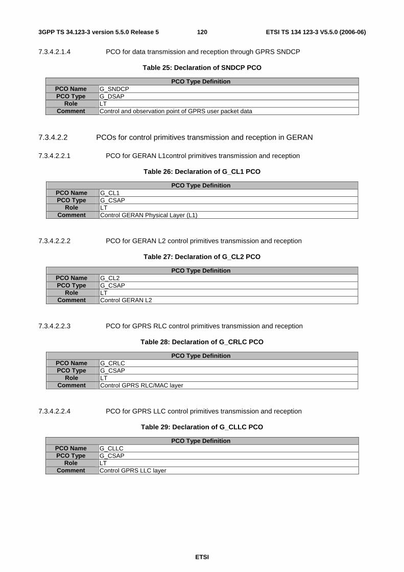
ETSI
ETSI TS 134 123-3 V5.5.0 (2006-06) 1203GPP TS 34.123-3 version 5.5.0 Release 5
7.3.4.2.1.4 PCO for data transmission and reception through GPRS SNDCP
Table 25: Declaration of SNDCP PCO
PCO Type Definition PCO Name G_SNDCP PCO Type G_DSAP
Role LT Comment Control and observation point of GPRS user packet data
7.3.4.2.2 PCOs for control primitives transmission and reception in GERAN
7.3.4.2.2.1 PCO for GERAN L1control primitives transmission and reception
Table 26: Declaration of G_CL1 PCO
PCO Type Definition PCO Name G_CL1 PCO Type G_CSAP
Role LT Comment Control GERAN Physical Layer (L1)
7.3.4.2.2.2 PCO for GERAN L2 control primitives transmission and reception
Table 27: Declaration of G_CL2 PCO
PCO Type Definition PCO Name G_CL2 PCO Type G_CSAP
Role LT Comment Control GERAN L2
7.3.4.2.2.3 PCO for GPRS RLC control primitives transmission and reception
Table 28: Declaration of G_CRLC PCO
PCO Type Definition PCO Name G_CRLC PCO Type G_CSAP
Role LT Comment Control GPRS RLC/MAC layer
7.3.4.2.2.4 PCO for GPRS LLC control primitives transmission and reception
Table 29: Declaration of G_CLLC PCO
PCO Type Definition PCO Name G_CLLC PCO Type G_CSAP
Role LT Comment Control GPRS LLC layer
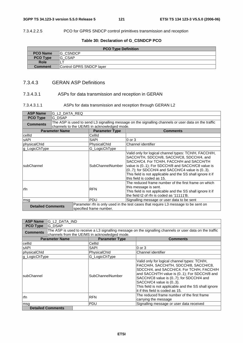
ETSI
ETSI TS 134 123-3 V5.5.0 (2006-06) 1213GPP TS 34.123-3 version 5.5.0 Release 5
7.3.4.2.2.5 PCO for GPRS SNDCP control primitives transmission and reception
Table 30: Declaration of G_CSNDCP PCO
PCO Type Definition PCO Name G_CSNDCP PCO Type G_CSAP
Role LT Comment Control GPRS SNDCP layer
7.3.4.3 GERAN ASP Definitions
7.3.4.3.1 ASPs for data transmission and reception in GERAN
7.3.4.3.1.1 ASPs for data transmission and reception through GERAN L2
ASP Name G_L2_DATA_REQ PCO Type G_DSAP
Comments The ASP is used to send L3 signalling message on the signalling channels or user data on the traffic channels to the UE/MS in acknowledged mode.
Parameter Name Parameter Type Comments cellId CellId sAPI SAPI 0 or 3 physicalChId PhysicalChId Channel identifier g_LogicChType G_LogicChType
subChannel SubChannelNumber
Valid only for logical channel types: TCH/H, FACCH/H, SACCH/TH, SDCCH/8, SACCH/C8, SDCCH/4, and SACCH/C4. For TCH/H, FACCH/H and SACCH/TH value is (0..1); For SDCCH/8 and SACCH/C8 value is (0..7); for SDCCH/4 and SACCH/C4 value is (0..3). This field is not applicable and the SS shall ignore it if this field is coded as 15.
rfn RFN
The reduced frame number of the first frame on which this message is sent. This field is not applicable and the SS shall ignore it if the field t2 of rfn is coded as '11111'B.
msg PDU Signalling message or user data to be sent
Detailed Comments Parameter rfn is only used in the test cases that require L3 message to be sent on specified frame number.
ASP Name G_L2_DATA_IND PCO Type G_DSAP
Comments The ASP is used to receive a L3 signalling message on the signalling channels or user data on the traffic channels from the UE/MS in acknowledged mode.
Parameter Name Parameter Type Comments cellId CellId sAPI SAPI 0 or 3 physicalChId PhysicalChId Channel identifier g_LogicChType G_LogicChType
subChannel SubChannelNumber
Valid only for logical channel types: TCH/H, FACCH/H, SACCH/TH, SDCCH/8, SACCH/C8, SDCCH/4, and SACCH/C4. For TCH/H, FACCH/H and SACCH/TH value is (0..1); For SDCCH/8 and SACCH/C8 value is (0..7); for SDCCH/4 and SACCH/C4 value is (0..3). This field is not applicable and the SS shall ignore it if this field is coded as 15.
rfn RFN The reduced frame number of the first frame carrying the message
msg PDU Signalling message or user data received Detailed Comments
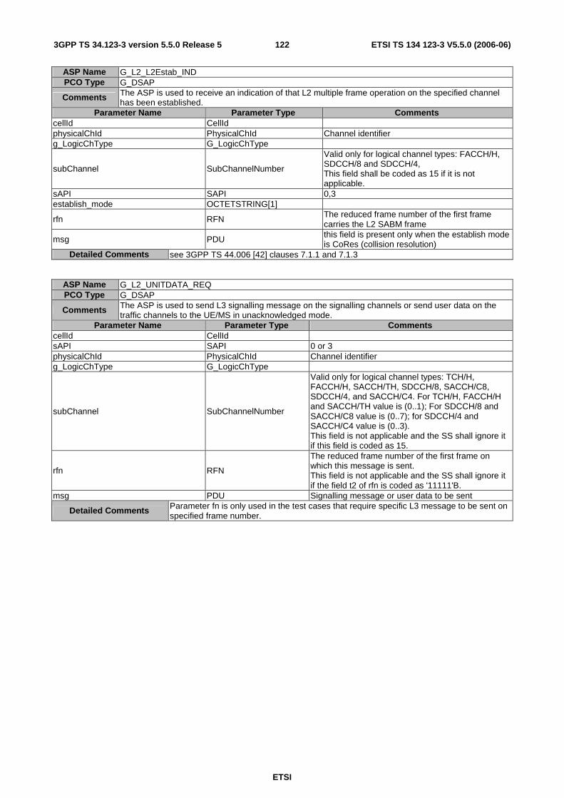
ETSI
ETSI TS 134 123-3 V5.5.0 (2006-06) 1223GPP TS 34.123-3 version 5.5.0 Release 5
ASP Name G_L2_L2Estab_IND PCO Type G_DSAP
Comments The ASP is used to receive an indication of that L2 multiple frame operation on the specified channel has been established.
Parameter Name Parameter Type Comments cellId CellId physicalChId PhysicalChId Channel identifier g_LogicChType G_LogicChType
subChannel SubChannelNumber
Valid only for logical channel types: FACCH/H, SDCCH/8 and SDCCH/4, This field shall be coded as 15 if it is not applicable.
sAPI SAPI 0,3 establish_mode OCTETSTRING[1]
rfn RFN The reduced frame number of the first frame carries the L2 SABM frame
msg PDU this field is present only when the establish mode is CoRes (collision resolution)
Detailed Comments see 3GPP TS 44.006 [42] clauses 7.1.1 and 7.1.3
ASP Name G_L2_UNITDATA_REQ PCO Type G_DSAP
Comments The ASP is used to send L3 signalling message on the signalling channels or send user data on the traffic channels to the UE/MS in unacknowledged mode.
Parameter Name Parameter Type Comments cellId CellId sAPI SAPI 0 or 3 physicalChId PhysicalChId Channel identifier g_LogicChType G_LogicChType
subChannel SubChannelNumber
Valid only for logical channel types: TCH/H, FACCH/H, SACCH/TH, SDCCH/8, SACCH/C8, SDCCH/4, and SACCH/C4. For TCH/H, FACCH/H and SACCH/TH value is (0..1); For SDCCH/8 and SACCH/C8 value is (0..7); for SDCCH/4 and SACCH/C4 value is (0..3). This field is not applicable and the SS shall ignore it if this field is coded as 15.
rfn RFN
The reduced frame number of the first frame on which this message is sent. This field is not applicable and the SS shall ignore it if the field t2 of rfn is coded as '11111'B.
msg PDU Signalling message or user data to be sent
Detailed Comments Parameter fn is only used in the test cases that require specific L3 message to be sent on specified frame number.
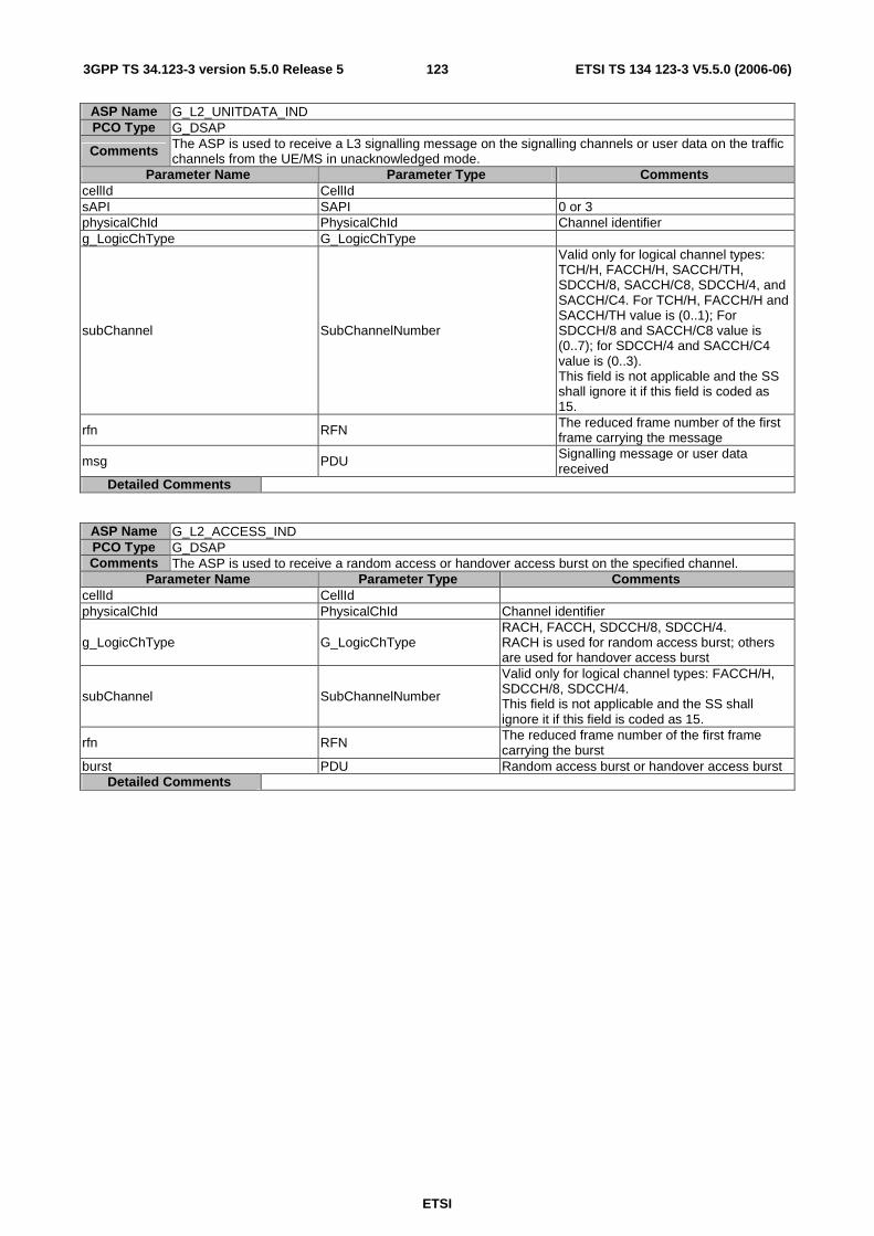
ETSI
ETSI TS 134 123-3 V5.5.0 (2006-06) 1233GPP TS 34.123-3 version 5.5.0 Release 5
ASP Name G_L2_UNITDATA_IND PCO Type G_DSAP
Comments The ASP is used to receive a L3 signalling message on the signalling channels or user data on the traffic channels from the UE/MS in unacknowledged mode.
Parameter Name Parameter Type Comments cellId CellId sAPI SAPI 0 or 3 physicalChId PhysicalChId Channel identifier g_LogicChType G_LogicChType
subChannel SubChannelNumber
Valid only for logical channel types: TCH/H, FACCH/H, SACCH/TH, SDCCH/8, SACCH/C8, SDCCH/4, and SACCH/C4. For TCH/H, FACCH/H and SACCH/TH value is (0..1); For SDCCH/8 and SACCH/C8 value is (0..7); for SDCCH/4 and SACCH/C4 value is (0..3). This field is not applicable and the SS shall ignore it if this field is coded as 15.
rfn RFN The reduced frame number of the first frame carrying the message
msg PDU Signalling message or user data received
Detailed Comments
ASP Name G_L2_ACCESS_IND PCO Type G_DSAP Comments The ASP is used to receive a random access or handover access burst on the specified channel.
Parameter Name Parameter Type Comments cellId CellId physicalChId PhysicalChId Channel identifier
g_LogicChType G_LogicChType RACH, FACCH, SDCCH/8, SDCCH/4. RACH is used for random access burst; others are used for handover access burst
subChannel SubChannelNumber
Valid only for logical channel types: FACCH/H, SDCCH/8, SDCCH/4. This field is not applicable and the SS shall ignore it if this field is coded as 15.
rfn RFN The reduced frame number of the first frame carrying the burst
burst PDU Random access burst or handover access burst Detailed Comments
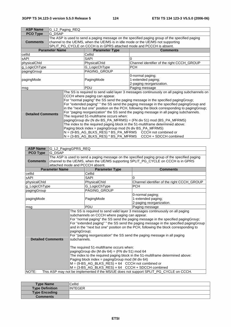
ETSI
ETSI TS 134 123-3 V5.5.0 (2006-06) 1243GPP TS 34.123-3 version 5.5.0 Release 5
ASP Name G_L2_Paging_REQ PCO Type G_DSAP
Comments The ASP is used to send a paging message on the specified paging group of the specified paging channel to the UE/MS, when the UE/MS is in idle mode or the UE/MS not supporting SPLIT_PG_CYCLE on CCCH is in GPRS attached mode and PCCCH is absent.
Parameter Name Parameter Type Comments cellId CellId sAPI SAPI 0 physicalChId PhysicalChId Channel identifier of the right CCCH_GROUP g_LogicChType G_LogicChType PCH pagingGroup PAGING_GROUP
pagingMode PagingMode 0-normal paging; 1-extended paging; 2-paging reorganization.
msg PDU Paging message
Detailed Comments
The SS is required to send valid layer 3 messages continuously on all paging subchannels on CCCH where paging can appear. For "normal paging" the SS send the paging message in the specified pagingGroup; For "extended paging" " the SS send the paging message in the specified pagingGroup and in the "next but one" position on the PCH, following the block corresponding to pagingGroup; For "paging reorganization" the SS send the paging message in all paging subchannels. The required 51-multiframe occurs when: pagingGroup div (N div BS_PA_MFRMS) = (FN div 51) mod (BS_PA_MFRMS) The index to the required paging block in the 51-multiframe determined above: Paging block index = pagingGroup mod (N div BS_PA_MFRMS) N = (9-BS_AG_BLKS_RES) * BS_PA_MFRMS CCCH not combined or N = (3-BS_AG_BLKS_RES) * BS_PA_MFRMS CCCH + SDCCH combined
ASP Name G_L2_PagingGPRS_REQ PCO Type G_DSAP
Comments The ASP is used to send a paging message on the specified paging group of the specified paging channel to the UE/MS, when the UE/MS supporting SPLIT_PG_CYCLE on CCCH is in GPRS attached mode and PCCCH absent.
Parameter Name Parameter Type Comments cellId CellId sAPI SAPI 0 physicalChId PhysicalChId Channel identifier of the right CCCH_GROUP g_LogicChType G_LogicChType PCH pagingGroup PAGING_GROUP
pagingMode PagingMode 0-normal paging; 1-extended paging; 2-paging reorganization.
msg PDU Paging message
Detailed Comments
The SS is required to send valid layer 3 messages continuously on all paging subchannels on CCCH where paging can appear. For "normal paging" the SS send the paging message in the specified pagingGroup; For "extended paging" " the SS send the paging message in the specified pagingGroup and in the "next but one" position on the PCH, following the block corresponding to pagingGroup; For "paging reorganization" the SS send the paging message in all paging subchannels. The required 51-multiframe occurs when: pagingGroup div (M div 64) = (FN div 51) mod 64 The index to the required paging block in the 51-multiframe determined above: Paging block index = pagingGroup mod (M div 64) M = (9-BS_AG_BLKS_RES) × 64 CCCH not combined or M = (3-BS_AG_BLKS_RES) × 64 CCCH + SDCCH combined
NOTE: This ASP may not be implemented if the MS/UE does not support SPLIT_PG_CYCLE on CCCH.
Type Name CellId Type Definition INTEGER Type Encoding
Comments
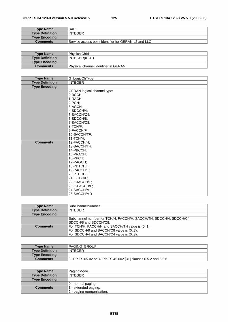
ETSI
ETSI TS 134 123-3 V5.5.0 (2006-06) 1253GPP TS 34.123-3 version 5.5.0 Release 5
Type Name SAPI Type Definition INTEGER Type Encoding
Comments Service access point identifier for GERAN L2 and LLC
Type Name PhysicalChId Type Definition INTEGER(0..31) Type Encoding
Comments Physical channel identifier in GERAN
Type Name G_LogicChType Type Definition INTEGER Type Encoding
Comments
GERAN logical channel type: 0-BCCH; 1-RACH; 2-PCH; 3-AGCH; 4-SDCCH/4; 5-SACCH/C4; 6-SDCCH/8; 7-SACCH/C8; 8-TCH/F; 9-FACCH/F; 10-SACCH/TF; 11-TCH/H; 12-FACCH/H; 13-SACCH/TH; 14-PBCCH; 15-PRACH; 16-PPCH; 17-PAGCH; 18-PDTCH/F; 19-PACCH/F; 20-PTCCH/F; 21-E-TCH/F; 22-E-IACCH/F; 23-E-FACCH/F; 24-SACCH/M; 25-SACCH/MD
Type Name SubChannelNumber Type Definition INTEGER Type Encoding
Comments
Subchannel number for TCH/H, FACCH/H, SACCH/TH, SDCCH/4, SDCCH/C4, SDCCH/8 and SDCCH/C8. For TCH/H, FACCH/H and SACCH/TH value is (0..1); For SDCCH/8 and SACCH/C8 value is (0..7); For SDCCH/4 and SACCH/C4 value is (0..3).
Type Name PAGING_GROUP Type Definition INTEGER Type Encoding
Comments 3GPP TS 05.02 or 3GPP TS 45.002 [31] clauses 6.5.2 and 6.5.6
Type Name PagingMode Type Definition INTEGER Type Encoding
Comments 0 - normal paging; 1 - extended paging; 2 - paging reorganization.
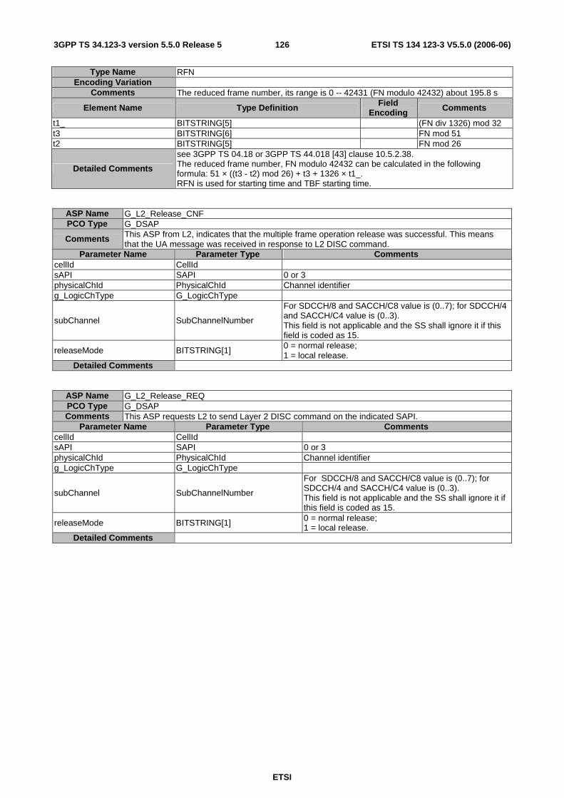
ETSI
ETSI TS 134 123-3 V5.5.0 (2006-06) 1263GPP TS 34.123-3 version 5.5.0 Release 5
Type Name RFN Encoding Variation
Comments The reduced frame number, its range is 0 -- 42431 (FN modulo 42432) about 195.8 s
Element Name Type Definition Field Encoding Comments
t1_ BITSTRING[5] (FN div 1326) mod 32 t3 BITSTRING[6] FN mod 51 t2 BITSTRING[5] FN mod 26
Detailed Comments
see 3GPP TS 04.18 or 3GPP TS 44.018 [43] clause 10.5.2.38. The reduced frame number, FN modulo 42432 can be calculated in the following formula: 51 × ((t3 - t2) mod 26) + t3 + 1326 × t1_. RFN is used for starting time and TBF starting time.
ASP Name G_L2_Release_CNF PCO Type G_DSAP
Comments This ASP from L2, indicates that the multiple frame operation release was successful. This means that the UA message was received in response to L2 DISC command.
Parameter Name Parameter Type Comments cellId CellId sAPI SAPI 0 or 3 physicalChId PhysicalChId Channel identifier g_LogicChType G_LogicChType
subChannel SubChannelNumber
For SDCCH/8 and SACCH/C8 value is (0..7); for SDCCH/4 and SACCH/C4 value is (0..3). This field is not applicable and the SS shall ignore it if this field is coded as 15.
releaseMode BITSTRING[1] 0 = normal release; 1 = local release.
Detailed Comments
ASP Name G_L2_Release_REQ PCO Type G_DSAP Comments This ASP requests L2 to send Layer 2 DISC command on the indicated SAPI.
Parameter Name Parameter Type Comments cellId CellId sAPI SAPI 0 or 3 physicalChId PhysicalChId Channel identifier g_LogicChType G_LogicChType
subChannel SubChannelNumber
For SDCCH/8 and SACCH/C8 value is (0..7); for SDCCH/4 and SACCH/C4 value is (0..3). This field is not applicable and the SS shall ignore it if this field is coded as 15.
releaseMode BITSTRING[1] 0 = normal release; 1 = local release.
Detailed Comments

ETSI
ETSI TS 134 123-3 V5.5.0 (2006-06) 1273GPP TS 34.123-3 version 5.5.0 Release 5
ASP Name G_L2_Release_IND PCO Type G_DSAP
Comments The ASP is used to receive an indication of the termination of an established multiple frame operation or an indication of an unsuccessful establishment attempt.
Parameter Name Parameter Type Comments cellId CellId sAPI SAPI 0 physicalChId PhysicalChId Channel identifier g_LogicChType G_LogicChType
subChannel SubChannelNumber
Valid only for logical channel types: TCH/H, FACCH/H, SACCH/TH, SDCCH/8, SACCH/C8, SDCCH/4, and SACCH/C4. For TCH/H, FACCH/H and SACCH/TH value is (0..1); for SDCCH/8 and SACCH/C8 value is (0..7); for SDCCH/4 and SACCH/C4 value is (0..3).
releaseMode BITSTRING[1] 0 = normal release; 1 = local end release
outstanding_Indicator BOOLEAN whether or not there are outstanding acknowledgements or unsolved G_L2_DATA_REQ primitives.
Detailed Comments
ASP Name G_L2_SYSINFO_REQ PCO Type G_DSAP Comments The ASP is used to send system information messages to the lower layer emulator.
Parameter Name Parameter Type Comments cellId CellId sAPI SAPI 0 physicalChId PhysicalChId g_LogicChType G_LogicChType BCCH or SACCH
instanceIndex INTEGER
To indicate the instance of the system information messages. For SYSTEM INFORMATION Type 2ter, 18, 19, 20 the value is (0..7); for type 14, 15 the value is (0..3); for type 2quater the value is (0..15); for all other type the value is 0.
sysInfoType SysInfoType SYSTEM INFORMATION Type 5, 5bis, 5ter, and 6 are sent on SACCH, the other SYSTEM INFORMATION 's are sent on BCCH.
BCCHExt B1 '0' indicates message sent on BCCH Norm, '1' indicates message sent on BCCH Ext. Only valid for SI 2quater, 7, 8, 13, 16, 17. Default value '0'
msg PDU
This field contains SYSTEM INFORMATION message. See 3GPP TS 44.018 [43] clause 9.1.31 to clause 9.1.43h for SYSTEM INFORMATION message definitions.
Detailed Comments
The lower layer emulator shall store the SYSTEM INFORMATION's, and transmit them periodically according to the rules specified in clause 6.3.1.3 of 3GPP TS 05.02 or 3GPP TS 45.002 [31]. The msg shall override the same type system information message previous stored in the lower layer emulator.
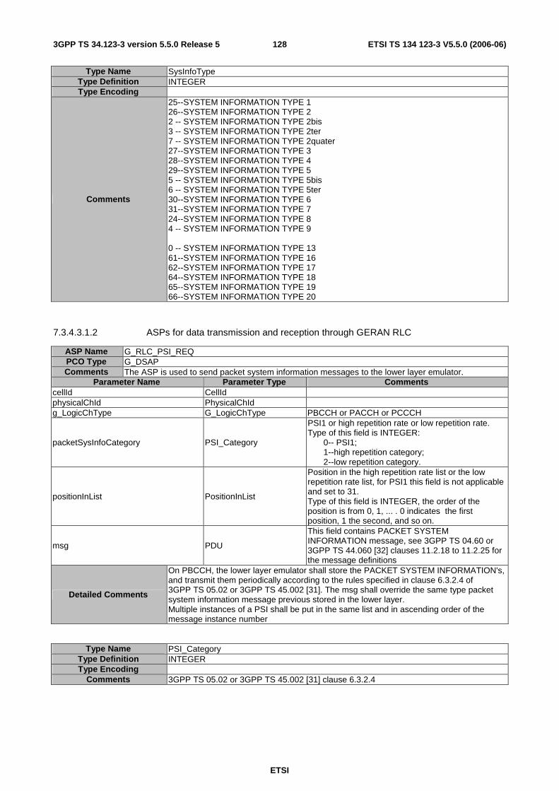
ETSI
ETSI TS 134 123-3 V5.5.0 (2006-06) 1283GPP TS 34.123-3 version 5.5.0 Release 5
Type Name SysInfoType Type Definition INTEGER Type Encoding
Comments
25--SYSTEM INFORMATION TYPE 1 26--SYSTEM INFORMATION TYPE 2 2 -- SYSTEM INFORMATION TYPE 2bis 3 -- SYSTEM INFORMATION TYPE 2ter 7 -- SYSTEM INFORMATION TYPE 2quater 27--SYSTEM INFORMATION TYPE 3 28--SYSTEM INFORMATION TYPE 4 29--SYSTEM INFORMATION TYPE 5 5 -- SYSTEM INFORMATION TYPE 5bis 6 -- SYSTEM INFORMATION TYPE 5ter 30--SYSTEM INFORMATION TYPE 6 31--SYSTEM INFORMATION TYPE 7 24--SYSTEM INFORMATION TYPE 8 4 -- SYSTEM INFORMATION TYPE 9 0 -- SYSTEM INFORMATION TYPE 13 61--SYSTEM INFORMATION TYPE 16 62--SYSTEM INFORMATION TYPE 17 64--SYSTEM INFORMATION TYPE 18 65--SYSTEM INFORMATION TYPE 19 66--SYSTEM INFORMATION TYPE 20
7.3.4.3.1.2 ASPs for data transmission and reception through GERAN RLC
ASP Name G_RLC_PSI_REQ PCO Type G_DSAP Comments The ASP is used to send packet system information messages to the lower layer emulator.
Parameter Name Parameter Type Comments cellId CellId physicalChId PhysicalChId g_LogicChType G_LogicChType PBCCH or PACCH or PCCCH
packetSysInfoCategory PSI_Category
PSI1 or high repetition rate or low repetition rate. Type of this field is INTEGER:
0-- PSI1; 1--high repetition category; 2--low repetition category.
positionInList PositionInList
Position in the high repetition rate list or the low repetition rate list, for PSI1 this field is not applicable and set to 31. Type of this field is INTEGER, the order of the position is from 0, 1, ... . 0 indicates the first position, 1 the second, and so on.
msg PDU
This field contains PACKET SYSTEM INFORMATION message, see 3GPP TS 04.60 or 3GPP TS 44.060 [32] clauses 11.2.18 to 11.2.25 for the message definitions
Detailed Comments
On PBCCH, the lower layer emulator shall store the PACKET SYSTEM INFORMATION's, and transmit them periodically according to the rules specified in clause 6.3.2.4 of 3GPP TS 05.02 or 3GPP TS 45.002 [31]. The msg shall override the same type packet system information message previous stored in the lower layer. Multiple instances of a PSI shall be put in the same list and in ascending order of the message instance number
Type Name PSI_Category Type Definition INTEGER Type Encoding
Comments 3GPP TS 05.02 or 3GPP TS 45.002 [31] clause 6.3.2.4

ETSI
ETSI TS 134 123-3 V5.5.0 (2006-06) 1293GPP TS 34.123-3 version 5.5.0 Release 5
Type Name PositionInList Type Definition INTEGER Type Encoding
Comments 0 is the first position; 1 is the second, and so on.
ASP Name G_RLC_ControlMsg_REQ PCO Type G_DSAP Comments The ASP is used to transmit a RLC/MAC control message to the UE/MS on the specified channel.
Parameter Name Parameter Type Comments cellId CellId physicalChId PhysicalChId g_LogicChType G_LogicChType PCCCH or PACCH or PTCCH
tBF_Direction INTEGER 1-downlink TBF; 0-uplink TBF
tFI TFI Temporary flow identity rRBP RRBP Relative reserved block period s_P_Bit S_P_Bit Supplementary/polling bit
rfn RFN
The reduced frame number of the first frame on which this message is sent. This field is not applicable and the SS shall ignore it if the field t2 of rfn is coded as '11111'B.
pagingGroup PAGING_GROUP for message other than PACKET PAGING REQUEST this field shall be omitted
pagingMode PagingMode
0 -- normal paging; 1-- extended paging; 3 -- paging reorganization. this field is valid only for PACKET PAGING REQUEST control message, for message other than PACKET PAGING REQUEST this field shall be omitted
msg PDU Down link RLC/MAC control message
Detailed Comments
This ASP provides values for "RRBP" and "S/P" fields in MAC header for TTCN controlling the response from the UE, the value for "PayloadType" and "USF" fields in MAC header shall be filled by the SS. If a RLC/MAC control message can not be fitted into one RLC/MAC control block, the SS RLC/MAC entity shall take the responsibility of segmentation of the message, and set the correct "PayloadType" and optional octet1 (and optional octet2). PTCCH is valid for PACKET TIMING ADVANCE/POWER CONTROL message if sending PACKET PAGING REQUEST. The required 52-multiframe occurs when: pagingGroup div (M div 64) = (FN div 52) mod 64 The index to the required paging block in the 51-multiframe determined above: Paging block index = pagingGroup mod (M div 64) M = (12 - BS_PAG_BLKS_RES - BS_PBCCH_BLKS) × 64
Type Name RRBP Type Definition BITSTRING[2] Type Encoding
Comments 3GPP TS 04.60 or 3GPP TS 44.060 [32] clause 10.4.5
Type Name S_P_Bit Type Definition BITSTRING[1] Type Encoding
Comments 0 - RRBP field is not valid; 1 - RRBP field is valid.
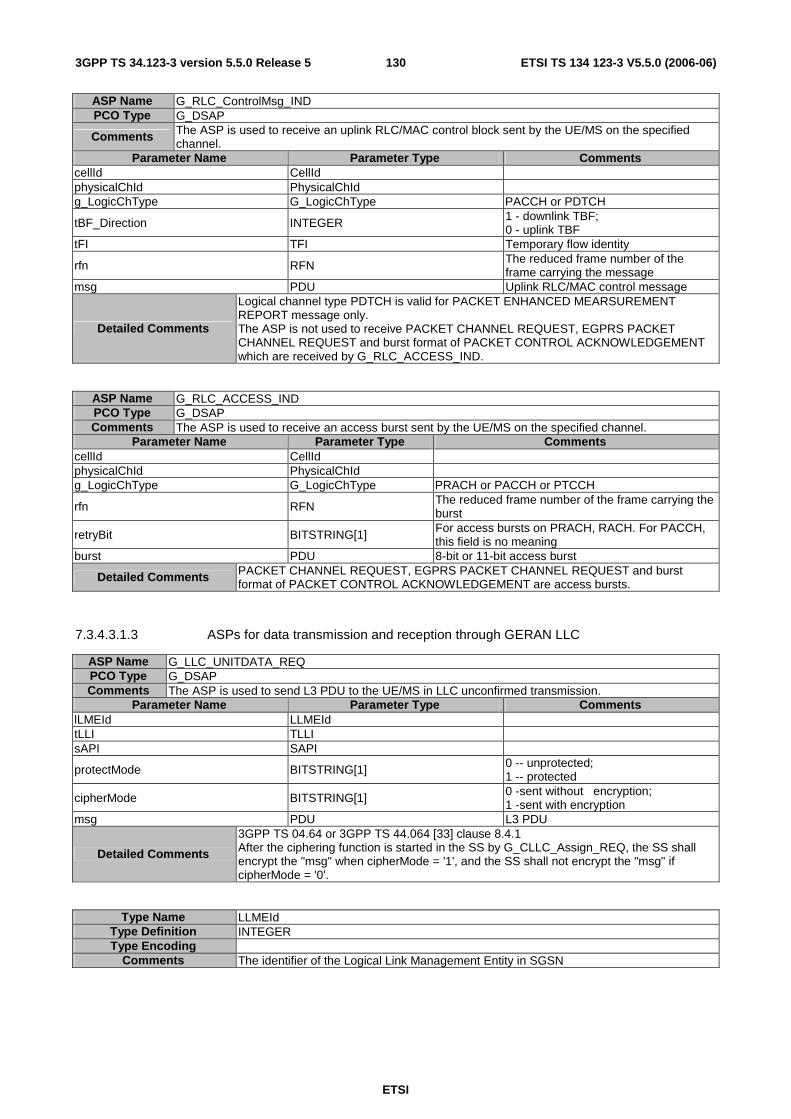
ETSI
ETSI TS 134 123-3 V5.5.0 (2006-06) 1303GPP TS 34.123-3 version 5.5.0 Release 5
ASP Name G_RLC_ControlMsg_IND PCO Type G_DSAP
Comments The ASP is used to receive an uplink RLC/MAC control block sent by the UE/MS on the specified channel.
Parameter Name Parameter Type Comments cellId CellId physicalChId PhysicalChId g_LogicChType G_LogicChType PACCH or PDTCH
tBF_Direction INTEGER 1 - downlink TBF; 0 - uplink TBF
tFI TFI Temporary flow identity
rfn RFN The reduced frame number of the frame carrying the message
msg PDU Uplink RLC/MAC control message
Detailed Comments
Logical channel type PDTCH is valid for PACKET ENHANCED MEARSUREMENT REPORT message only. The ASP is not used to receive PACKET CHANNEL REQUEST, EGPRS PACKET CHANNEL REQUEST and burst format of PACKET CONTROL ACKNOWLEDGEMENT which are received by G_RLC_ACCESS_IND.
ASP Name G_RLC_ACCESS_IND PCO Type G_DSAP Comments The ASP is used to receive an access burst sent by the UE/MS on the specified channel.
Parameter Name Parameter Type Comments cellId CellId physicalChId PhysicalChId g_LogicChType G_LogicChType PRACH or PACCH or PTCCH
rfn RFN The reduced frame number of the frame carrying the burst
retryBit BITSTRING[1] For access bursts on PRACH, RACH. For PACCH, this field is no meaning
burst PDU 8-bit or 11-bit access burst
Detailed Comments PACKET CHANNEL REQUEST, EGPRS PACKET CHANNEL REQUEST and burst format of PACKET CONTROL ACKNOWLEDGEMENT are access bursts.
7.3.4.3.1.3 ASPs for data transmission and reception through GERAN LLC
ASP Name G_LLC_UNITDATA_REQ PCO Type G_DSAP Comments The ASP is used to send L3 PDU to the UE/MS in LLC unconfirmed transmission.
Parameter Name Parameter Type Comments lLMEId LLMEId tLLI TLLI sAPI SAPI
protectMode BITSTRING[1] 0 -- unprotected; 1 -- protected
cipherMode BITSTRING[1] 0 -sent without encryption; 1 -sent with encryption
msg PDU L3 PDU
Detailed Comments
3GPP TS 04.64 or 3GPP TS 44.064 [33] clause 8.4.1 After the ciphering function is started in the SS by G_CLLC_Assign_REQ, the SS shall encrypt the "msg" when cipherMode = '1', and the SS shall not encrypt the "msg" if cipherMode = '0'.
Type Name LLMEId Type Definition INTEGER Type Encoding
Comments The identifier of the Logical Link Management Entity in SGSN

ETSI
ETSI TS 134 123-3 V5.5.0 (2006-06) 1313GPP TS 34.123-3 version 5.5.0 Release 5
ASP Name G_LLC_UNITDATA_IND PCO Type G_DSAP Comments The ASP is used to receive a L3 PDU from the UE/MS in LLC unconfirmed transmission.
Parameter Name Parameter Type Comments lLMEId LLMEId tLLI TLLI sAPI SAPI msg PDU L3 PDU
Detailed Comments 3GPP TS 04.64 or 3GPP TS 44.064 [33] clause 8.4.2
ASP Name G_LLC_XID_RES PCO Type G_DSAP Comments The ASP is used to send to the UE/MS the negotiated XID parameters agreed by the SS.
Parameter Name Parameter Type Comments lLMEId LLMEId tLLI TLLI sAPI SAPI
xID_Info XID_Info the negotiated XID parameters agreed by the SS
Detailed Comments
Type Name XID_Info Type Definition OCTETSTRING Type Encoding
Comments Exchange Identification Information
ASP Name G_LLC_XID_IND PCO Type G_DSAP Comments The ASP is used to receive the XID requested by the UE/MS.
Parameter Name Parameter Type Comments lLMEId LLMEId tLLI TLLI sAPI SAPI
xID_Info XID_Info the XID parameters requested by the UE/MS
Detailed Comments
7.3.4.3.1.4 ASPs for data transmission and reception through GERAN SNDCP
ASP Name G_SN_DATA_REQ PCO Type G_DSAP
Comments The ASP is used to send a valid IP datagram on the specified NSAPI to the UE/MS by acknowledged transmission.
Parameter Name Parameter Type Comments sNDCPId SNDCPId nSAPI NSAPI 5 to 15 n_PDU_Number OCTETSTRING[1] n_PDU N_PDU Valid IPv4 or IPv6 datagram
Detailed Comments Acknowledged transmission mode
ASP Name G_SN_DATA_IND PCO Type G_DSAP
Comments The ASP is used to receive an IP datagram on the specified NASPI from the UE/MS in acknowledged transmission mode.
Parameter Name Parameter Type Comments sNDCPId SNDCPId nSAPI NSAPI 5 to 15 n_PDU N_PDU IPv4 or IPv6 datagram
Detailed Comments Acknowledged transmission mode
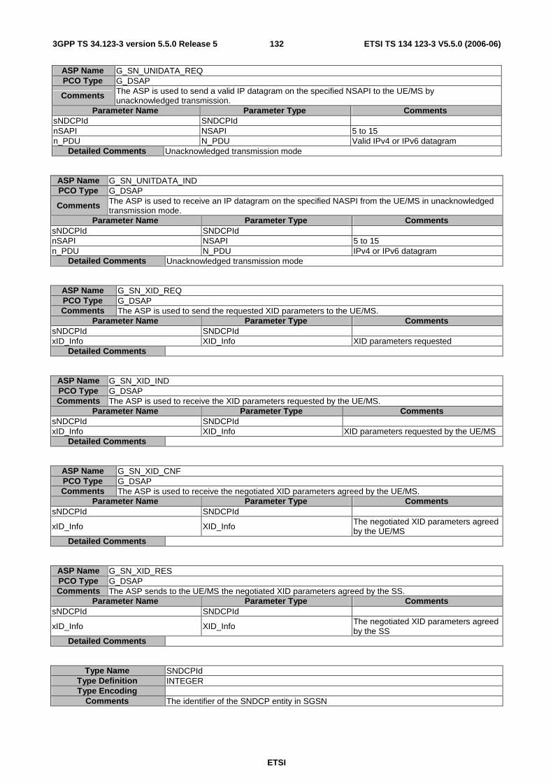
ETSI
ETSI TS 134 123-3 V5.5.0 (2006-06) 1323GPP TS 34.123-3 version 5.5.0 Release 5
ASP Name G_SN_UNIDATA_REQ PCO Type G_DSAP
Comments The ASP is used to send a valid IP datagram on the specified NSAPI to the UE/MS by unacknowledged transmission.
Parameter Name Parameter Type Comments sNDCPId SNDCPId nSAPI NSAPI 5 to 15 n_PDU N_PDU Valid IPv4 or IPv6 datagram
Detailed Comments Unacknowledged transmission mode
ASP Name G_SN_UNITDATA_IND PCO Type G_DSAP
Comments The ASP is used to receive an IP datagram on the specified NASPI from the UE/MS in unacknowledged transmission mode.
Parameter Name Parameter Type Comments sNDCPId SNDCPId nSAPI NSAPI 5 to 15 n_PDU N_PDU IPv4 or IPv6 datagram
Detailed Comments Unacknowledged transmission mode
ASP Name G_SN_XID_REQ PCO Type G_DSAP Comments The ASP is used to send the requested XID parameters to the UE/MS.
Parameter Name Parameter Type Comments sNDCPId SNDCPId xID_Info XID_Info XID parameters requested
Detailed Comments
ASP Name G_SN_XID_IND PCO Type G_DSAP Comments The ASP is used to receive the XID parameters requested by the UE/MS.
Parameter Name Parameter Type Comments sNDCPId SNDCPId xID_Info XID_Info XID parameters requested by the UE/MS
Detailed Comments
ASP Name G_SN_XID_CNF PCO Type G_DSAP Comments The ASP is used to receive the negotiated XID parameters agreed by the UE/MS.
Parameter Name Parameter Type Comments sNDCPId SNDCPId
xID_Info XID_Info The negotiated XID parameters agreed by the UE/MS
Detailed Comments
ASP Name G_SN_XID_RES PCO Type G_DSAP Comments The ASP sends to the UE/MS the negotiated XID parameters agreed by the SS.
Parameter Name Parameter Type Comments sNDCPId SNDCPId
xID_Info XID_Info The negotiated XID parameters agreed by the SS
Detailed Comments
Type Name SNDCPId Type Definition INTEGER Type Encoding
Comments The identifier of the SNDCP entity in SGSN

ETSI
ETSI TS 134 123-3 V5.5.0 (2006-06) 1333GPP TS 34.123-3 version 5.5.0 Release 5
7.3.4.3.1.5 ASPs for data transmission and reception through GERAN DTM
ASP Name G_L2_GTTP_REQ PCO Type G_DSAP Comments The ASP is used for DTM to send an LLC signalling message on the DCCH in acknowledged mode.
Parameter Name Parameter Type Comments cellId CellId SAPI SAPI physicalChId PhysicalChId Channel identifier g_LogicChType G_LogicChType
subChannel SubChannelNumber
Valid only for logical channel types: TCH/H, FACCH/H, SACCH/TH, SDCCH/8, SACCH/C8, SDCCH/4, and SACCH/C4. For TCH/H, FACCH/H and SACCH/TH value is (0..1); For SDCCH/8 and SACCH/C8 value is (0..7); for SDCCH/4 and SACCH/C4 value is (0..3). This field is not applicable and the SS shall ignore it if this field is coded as 15.
protectMode BITSTRING[1] 0 -- unprotected; 1 -- protected
cipherMode BITSTRING[1] 0 -sent without encryption; 1 -sent with encryption
skipIndicator B4 GTTP header, unciphered GTTPProtocolDiscriminator B4 GTTP header, unciphered msgType B8 GTTP header, unciphered TLLI TLLI GTTP header, unciphered LLCPDULength Length GTTP header, unciphered LLCPDU PDU LLC PDU - ciphered
Detailed Comments
Ciphering must be started in the SS by G_CLLC_Assign_REQ , and also by either G_CL1_CipheringControl_REQ, G_CL1_CipherModeModify_REQ, or G_CL1_CreateBasicPhyCh_REQ. When cipherMode = '1' the SS shall encrypt the "LLCPDU', using the algorithm specified in px_GPRS_CipherAlg, and then encrypt the whole outgoing message using the algorithm specified in px_GSM_CipherAlg. The SS shall not encrypt the message at all if cipherMode = '0'.
ASP Name G_L2_GTTP_IND PCO Type G_DSAP Comments The ASP is used for DTM to receive an LLC signalling message on DCCH acknowledged mode.
Parameter Name Parameter Type Comments cellId CellId SAPI SAPI physicalChId PhysicalChId Channel identifier g_LogicChType G_LogicChType
subChannel SubChannelNumber
Valid only for logical channel types: TCH/H, FACCH/H, SACCH/TH, SDCCH/8, SACCH/C8, SDCCH/4, and SACCH/C4. For TCH/H, FACCH/H and SACCH/TH value is (0..1); For SDCCH/8 and SACCH/C8 value is (0..7); for SDCCH/4 and SACCH/C4 value is (0..3). This field is not applicable and the SS shall ignore it if this field is coded as 15.
rfn RFN The reduced frame number of the first frame carrying the message
TLLI TLLI LLC PDU PDU Deciphered signalling message received
Detailed Comments If ciphering is used, the SS will take care to ensure the 'LLC PDU' is deciphered

ETSI
ETSI TS 134 123-3 V5.5.0 (2006-06) 1343GPP TS 34.123-3 version 5.5.0 Release 5
7.3.4.3.2 ASPs for control primitive transmission and reception in GERAN
7.3.4.3.2.1 ASPs for configuration and control of GERAN L1
ASP Name G_CL1_CreateCell_REQ PCO Type G_CSAP Comments The ASP is used to create a cell in GERAN
Parameter Name Parameter Type Comments cellId CellId
baseId BITSTRING[6] base transceiver station identity code = NCC+BCC. see 3GPP TS 23.003 [6]
timingAdvance BITSTRING[8] The SS sets the timing of uplink direction in advance of downlink direction timing by this value.
Detailed Comments
ASP Name G_CL1_CreateCell_CNF PCO Type G_CSAP Comments The ASP is used to get the confirmation of a G_CL1_CreateCell_REQ
Parameter Name Parameter Type Comments cellId CellId The cell created
Detailed Comments
ASP Name G_CL1_DeleteCell_REQ PCO Type G_CSAP Comments The ASP is used to delete a cell in GERAN
Parameter Name Parameter Type Comments cellId CellId The cell to be deleted
Detailed Comments
ASP Name G_CL1_DeleteCell_CNF PCO Type G_CSAP Comments The ASP is used to get the confirmation of a G_CL1_DeleteCell_REQ
Parameter Name Parameter Type Comments cellId CellId The cell deleted
Detailed Comments
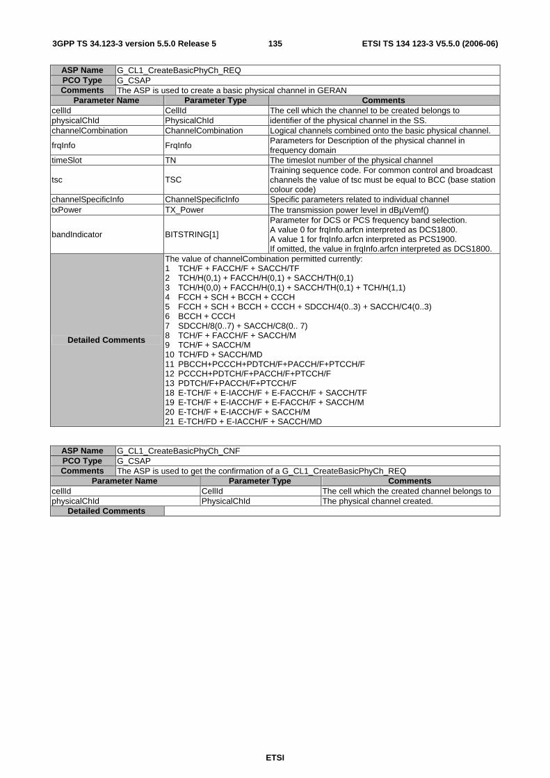
ETSI
ETSI TS 134 123-3 V5.5.0 (2006-06) 1353GPP TS 34.123-3 version 5.5.0 Release 5
ASP Name G_CL1_CreateBasicPhyCh_REQ PCO Type G_CSAP Comments The ASP is used to create a basic physical channel in GERAN
Parameter Name Parameter Type Comments cellId CellId The cell which the channel to be created belongs to physicalChId PhysicalChId identifier of the physical channel in the SS. channelCombination ChannelCombination Logical channels combined onto the basic physical channel.
frqInfo FrqInfo Parameters for Description of the physical channel in frequency domain
timeSlot TN The timeslot number of the physical channel
tsc TSC Training sequence code. For common control and broadcast channels the value of tsc must be equal to BCC (base station colour code)
channelSpecificInfo ChannelSpecificInfo Specific parameters related to individual channel txPower TX_Power The transmission power level in dBµVemf()
bandIndicator BITSTRING[1]
Parameter for DCS or PCS frequency band selection. A value 0 for frqInfo.arfcn interpreted as DCS1800. A value 1 for frqInfo.arfcn interpreted as PCS1900. If omitted, the value in frqInfo.arfcn interpreted as DCS1800.
Detailed Comments
The value of channelCombination permitted currently: 1 TCH/F + FACCH/F + SACCH/TF 2 TCH/H(0,1) + FACCH/H(0,1) + SACCH/TH(0,1) 3 TCH/H(0,0) + FACCH/H(0,1) + SACCH/TH(0,1) + TCH/H(1,1) 4 FCCH + SCH + BCCH + CCCH 5 FCCH + SCH + BCCH + CCCH + SDCCH/4(0..3) + SACCH/C4(0..3) 6 BCCH + CCCH 7 SDCCH/8(0..7) + SACCH/C8(0.. 7) 8 TCH/F + FACCH/F + SACCH/M 9 TCH/F + SACCH/M 10 TCH/FD + SACCH/MD 11 PBCCH+PCCCH+PDTCH/F+PACCH/F+PTCCH/F 12 PCCCH+PDTCH/F+PACCH/F+PTCCH/F 13 PDTCH/F+PACCH/F+PTCCH/F 18 E-TCH/F + E-IACCH/F + E-FACCH/F + SACCH/TF 19 E-TCH/F + E-IACCH/F + E-FACCH/F + SACCH/M 20 E-TCH/F + E-IACCH/F + SACCH/M 21 E-TCH/FD + E-IACCH/F + SACCH/MD
ASP Name G_CL1_CreateBasicPhyCh_CNF PCO Type G_CSAP Comments The ASP is used to get the confirmation of a G_CL1_CreateBasicPhyCh_REQ
Parameter Name Parameter Type Comments cellId CellId The cell which the created channel belongs to physicalChId PhysicalChId The physical channel created.
Detailed Comments
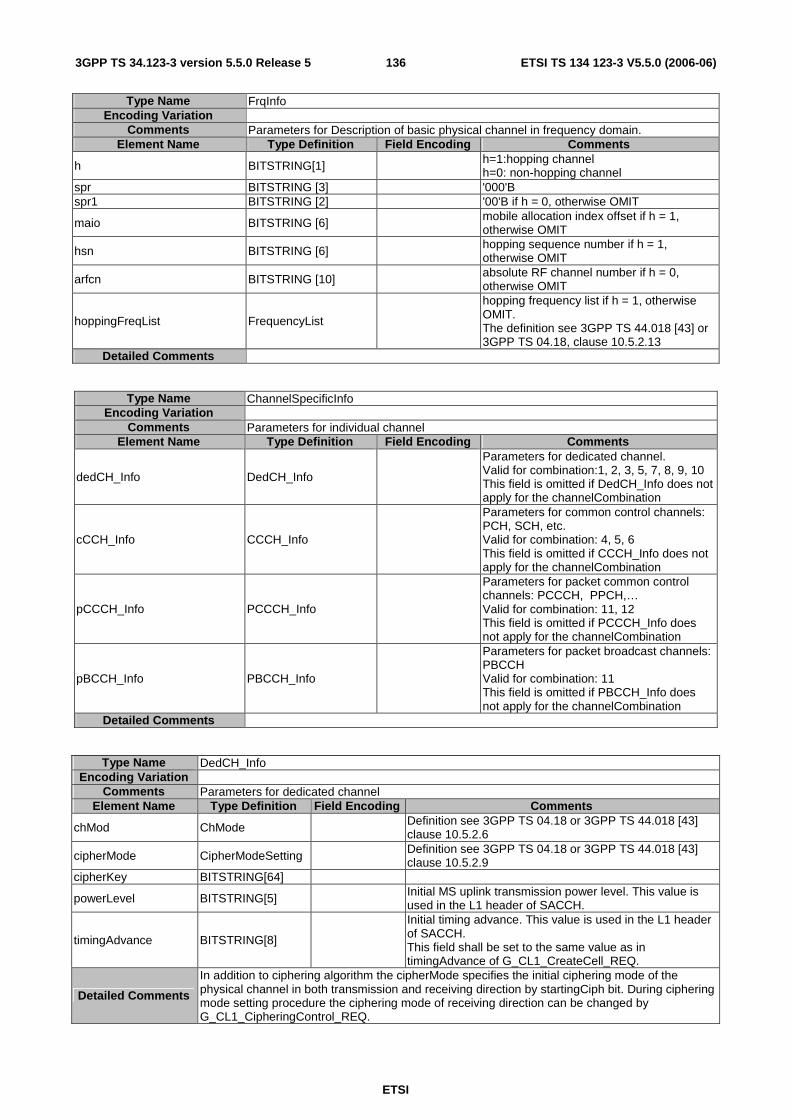
ETSI
ETSI TS 134 123-3 V5.5.0 (2006-06) 1363GPP TS 34.123-3 version 5.5.0 Release 5
Type Name FrqInfo Encoding Variation
Comments Parameters for Description of basic physical channel in frequency domain. Element Name Type Definition Field Encoding Comments
h BITSTRING[1] h=1:hopping channel h=0: non-hopping channel
spr BITSTRING [3] '000'B spr1 BITSTRING [2] '00'B if h = 0, otherwise OMIT
maio BITSTRING [6] mobile allocation index offset if h = 1, otherwise OMIT
hsn BITSTRING [6] hopping sequence number if h = 1, otherwise OMIT
arfcn BITSTRING [10] absolute RF channel number if h = 0, otherwise OMIT
hoppingFreqList FrequencyList
hopping frequency list if h = 1, otherwise OMIT. The definition see 3GPP TS 44.018 [43] or 3GPP TS 04.18, clause 10.5.2.13
Detailed Comments
Type Name ChannelSpecificInfo Encoding Variation
Comments Parameters for individual channel Element Name Type Definition Field Encoding Comments
dedCH_Info DedCH_Info
Parameters for dedicated channel. Valid for combination:1, 2, 3, 5, 7, 8, 9, 10 This field is omitted if DedCH_Info does not apply for the channelCombination
cCCH_Info CCCH_Info
Parameters for common control channels: PCH, SCH, etc. Valid for combination: 4, 5, 6 This field is omitted if CCCH_Info does not apply for the channelCombination
pCCCH_Info PCCCH_Info
Parameters for packet common control channels: PCCCH, PPCH,… Valid for combination: 11, 12 This field is omitted if PCCCH_Info does not apply for the channelCombination
pBCCH_Info PBCCH_Info
Parameters for packet broadcast channels: PBCCH Valid for combination: 11 This field is omitted if PBCCH_Info does not apply for the channelCombination
Detailed Comments
Type Name DedCH_Info Encoding Variation
Comments Parameters for dedicated channel Element Name Type Definition Field Encoding Comments
chMod ChMode Definition see 3GPP TS 04.18 or 3GPP TS 44.018 [43] clause 10.5.2.6
cipherMode CipherModeSetting Definition see 3GPP TS 04.18 or 3GPP TS 44.018 [43] clause 10.5.2.9
cipherKey BITSTRING[64]
powerLevel BITSTRING[5] Initial MS uplink transmission power level. This value is used in the L1 header of SACCH.
timingAdvance BITSTRING[8]
Initial timing advance. This value is used in the L1 header of SACCH. This field shall be set to the same value as in timingAdvance of G_CL1_CreateCell_REQ.
Detailed Comments
In addition to ciphering algorithm the cipherMode specifies the initial ciphering mode of the physical channel in both transmission and receiving direction by startingCiph bit. During ciphering mode setting procedure the ciphering mode of receiving direction can be changed by G_CL1_CipheringControl_REQ.

ETSI
ETSI TS 134 123-3 V5.5.0 (2006-06) 1373GPP TS 34.123-3 version 5.5.0 Release 5
Type Name CCCH_Info Encoding Variation
Comments Parameters for common control channels Element Name Type Definition Field Encoding Comments
bS_PA_MFRMS BITSTRING[3] the number of 51-multiframes between transmissions of paging messages. Definition see 3GPP TS 04.18 or 3GPP TS 44.018 [43] clause 10.5.2.11
bS_AG_BLKS_RES BITSTRING[3]
the number of blocks on each common control channel reserved for access grant messages. Definition see 3GPP TS 04.18 or 3GPP TS 44.018 [43] clause 10.5.2.11
Detailed Comments
Type Name PCCCH_Info Encoding Variation
Comments Parameters for packet common control channels Element Name Type Definition Field Encoding Comments
bS_PBCCH_BLKS BITSTRING[2] 3GPP TS 04.60 or 3GPP TS 44.060 [32] clause 12.25
bS_PAG_BLKS_RES BITSTRING[4] 3GPP TS 04.60 or 3GPP TS 44.060 [32] clause 12.25
bS_PRACH_BLKS BITSTRING[4] 3GPP TS 04.60 or 3GPP TS 44.060 [32] clause 12.25
Detailed Comments
Type Name PBCCH_Info Encoding Variation
Comments Parameters for packet broadcast channel Element Name Type Definition Field Encoding Comments
pSI1_REPEAT_PERIOD BITSTRING[4] The repeat period of packet system information Type 1. See 3GPP TS 04.60 or 3GPP TS 44.060 [32] clause 11.2.18
pSI_COUNT_HR BITSTRING[4] The number of PSI message instances sent with high repetition rate. See 3GPP TS 04.60 or 3GPP TS 44.060 [32] clause 11.2.18
pSI_COUNT_LR BITSTRING[6] The number of PSI message instances sent with low repetition rate. See 3GPP TS 04.60 or 3GPP TS 44.060 [32] clause 11.2.18
Detailed Comments
ASP Name G_CL1_CreateMultiSlotConfig_REQ PCO Type G_CSAP
Comments The ASP is used to create a multi-slot configuration in GERAN and should be preceded with G_CL1_CreateBasicPhyCh_REQ in order to create a basic physical channel with single timeslot.
Parameter Name Parameter Type Comments cellId CellId The cell which the configuration to be created belongs to mainChannel PhysicalChId identifier of the main physical channel of this multi-slot configuration. multiSlotAllocation MultiSlotAllocation The timeslot allocation of the configuration
Detailed Comments This ASP is to add a multi-slot configuration to the physical channel created in G_CL1_CreateBasicPhyCh_REQ ASP. For multi-slot configuration refer 3GPP TS 05.02 or 3GPP TS 45.002 [31] clause 6.4.2.
ASP Name G_CL1_CreateMultiSlotConfig_CNF PCO Type G_CSAP Comments The ASP is used to get the confirmation of a G_CL1_CreateMultiSlotConfig_REQ
Parameter Name Parameter Type Comments cellId CellId The cell which the created multi-slot configuration belongs to. physicalChId PhysicalChId The main physical channel identifier.
Detailed Comments
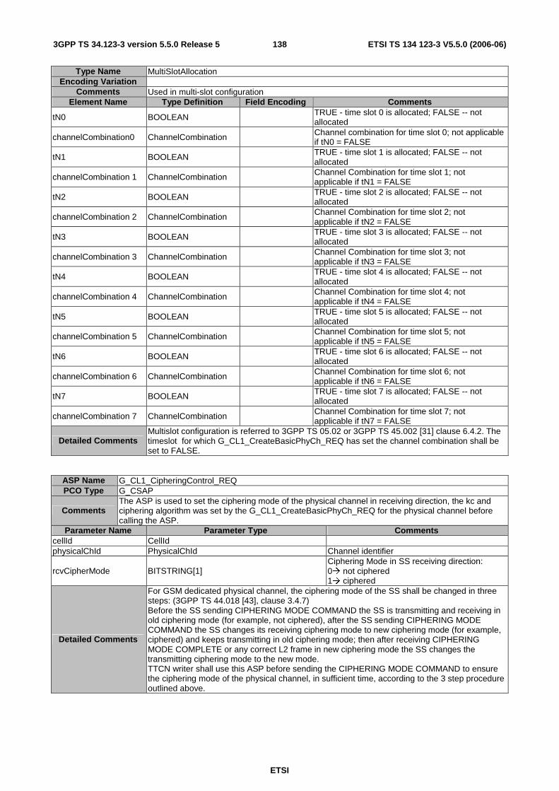
ETSI
ETSI TS 134 123-3 V5.5.0 (2006-06) 1383GPP TS 34.123-3 version 5.5.0 Release 5
Type Name MultiSlotAllocation Encoding Variation
Comments Used in multi-slot configuration Element Name Type Definition Field Encoding Comments
tN0 BOOLEAN TRUE - time slot 0 is allocated; FALSE -- not allocated
channelCombination0 ChannelCombination Channel combination for time slot 0; not applicable if tN0 = FALSE
tN1 BOOLEAN TRUE - time slot 1 is allocated; FALSE -- not allocated
channelCombination 1 ChannelCombination Channel Combination for time slot 1; not applicable if tN1 = FALSE
tN2 BOOLEAN TRUE - time slot 2 is allocated; FALSE -- not allocated
channelCombination 2 ChannelCombination Channel Combination for time slot 2; not applicable if tN2 = FALSE
tN3 BOOLEAN TRUE - time slot 3 is allocated; FALSE -- not allocated
channelCombination 3 ChannelCombination Channel Combination for time slot 3; not applicable if tN3 = FALSE
tN4 BOOLEAN TRUE - time slot 4 is allocated; FALSE -- not allocated
channelCombination 4 ChannelCombination Channel Combination for time slot 4; not applicable if tN4 = FALSE
tN5 BOOLEAN TRUE - time slot 5 is allocated; FALSE -- not allocated
channelCombination 5 ChannelCombination Channel Combination for time slot 5; not applicable if tN5 = FALSE
tN6 BOOLEAN TRUE - time slot 6 is allocated; FALSE -- not allocated
channelCombination 6 ChannelCombination Channel Combination for time slot 6; not applicable if tN6 = FALSE
tN7 BOOLEAN TRUE - time slot 7 is allocated; FALSE -- not allocated
channelCombination 7 ChannelCombination Channel Combination for time slot 7; not applicable if tN7 = FALSE
Detailed Comments Multislot configuration is referred to 3GPP TS 05.02 or 3GPP TS 45.002 [31] clause 6.4.2. The timeslot for which G_CL1_CreateBasicPhyCh_REQ has set the channel combination shall be set to FALSE.
ASP Name G_CL1_CipheringControl_REQ PCO Type G_CSAP
Comments The ASP is used to set the ciphering mode of the physical channel in receiving direction, the kc and ciphering algorithm was set by the G_CL1_CreateBasicPhyCh_REQ for the physical channel before calling the ASP.
Parameter Name Parameter Type Comments cellId CellId physicalChId PhysicalChId Channel identifier
rcvCipherMode BITSTRING[1] Ciphering Mode in SS receiving direction: 0� not ciphered 1� ciphered
Detailed Comments
For GSM dedicated physical channel, the ciphering mode of the SS shall be changed in three steps: (3GPP TS 44.018 [43], clause 3.4.7) Before the SS sending CIPHERING MODE COMMAND the SS is transmitting and receiving in old ciphering mode (for example, not ciphered), after the SS sending CIPHERING MODE COMMAND the SS changes its receiving ciphering mode to new ciphering mode (for example, ciphered) and keeps transmitting in old ciphering mode; then after receiving CIPHERING MODE COMPLETE or any correct L2 frame in new ciphering mode the SS changes the transmitting ciphering mode to the new mode. TTCN writer shall use this ASP before sending the CIPHERING MODE COMMAND to ensure the ciphering mode of the physical channel, in sufficient time, according to the 3 step procedure outlined above.
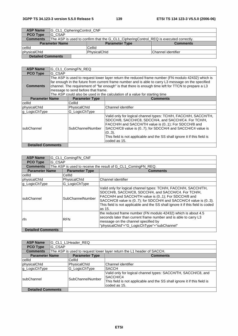
ETSI
ETSI TS 134 123-3 V5.5.0 (2006-06) 1393GPP TS 34.123-3 version 5.5.0 Release 5
ASP Name G_CL1_CipheringControl_CNF PCO Type G_CSAP Comments The ASP is used to confirm that the G_CL1_CipheringControl_REQ is executed correctly.
Parameter Name Parameter Type Comments cellId CellId physicalChId PhysicalChId Channel identifier
Detailed Comments
ASP Name G_CL1_ComingFN_REQ PCO Type G_CSAP
Comments
The ASP is used to request lower layer return the reduced frame number (FN modulo 42432) which is far enough in the future from current frame number and is able to carry L3 message on the specified channel. The requirement of "far enough" is that there is enough time left for TTCN to prepare a L3 message to send before that frame. The ASP could also be used in the calculation of a value for starting time
Parameter Name Parameter Type Comments cellId CellId physicalChId PhysicalChId Channel identifier g_LogicChType G_LogicChType
subChannel SubChannelNumber
Valid only for logical channel types: TCH/H, FACCH/H, SACCH/TH, SDCCH/8, SACCH/C8, SDCCH/4, and SACCH/C4. For TCH/H, FACCH/H and SACCH/TH value is (0..1); For SDCCH/8 and SACCH/C8 value is (0..7); for SDCCH/4 and SACCH/C4 value is (0..3). This field is not applicable and the SS shall ignore it if this field is coded as 15.
Detailed Comments
ASP Name G_CL1_ComingFN_CNF PCO Type G_CSAP Comments The ASP is used to receive the result of G_CL1_ComingFN_REQ. Parameter Name Parameter Type Comments
cellId CellId physicalChId PhysicalChId Channel identifier g_LogicChType G_LogicChType
subChannel SubChannelNumber
Valid only for logical channel types: TCH/H, FACCH/H, SACCH/TH, SDCCH/8, SACCH/C8, SDCCH/4, and SACCH/C4. For TCH/H, FACCH/H and SACCH/TH value is (0..1); For SDCCH/8 and SACCH/C8 value is (0..7); for SDCCH/4 and SACCH/C4 value is (0..3). This field is not applicable and the SS shall ignore it if this field is coded as 15.
rfn RFN
the reduced frame number (FN modulo 42432) which is about 4.5 seconds later than current frame number and is able to carry L3 message on the channel specified by "physicalChId"+"G_LogicChType"+"subChannel"
Detailed Comments
ASP Name G_CL1_L1Header_REQ PCO Type G_CSAP Comments The ASP is used to request lower layer return the L1 header of SACCH.
Parameter Name Parameter Type Comments cellId CellId physicalChId PhysicalChId Channel identifier g_LogicChType G_LogicChType SACCH
subChannel SubChannelNumber
Valid only for logical channel types: SACCH/TH, SACCH/C8, and SACCH/C4 This field is not applicable and the SS shall ignore it if this field is coded as 15.
Detailed Comments
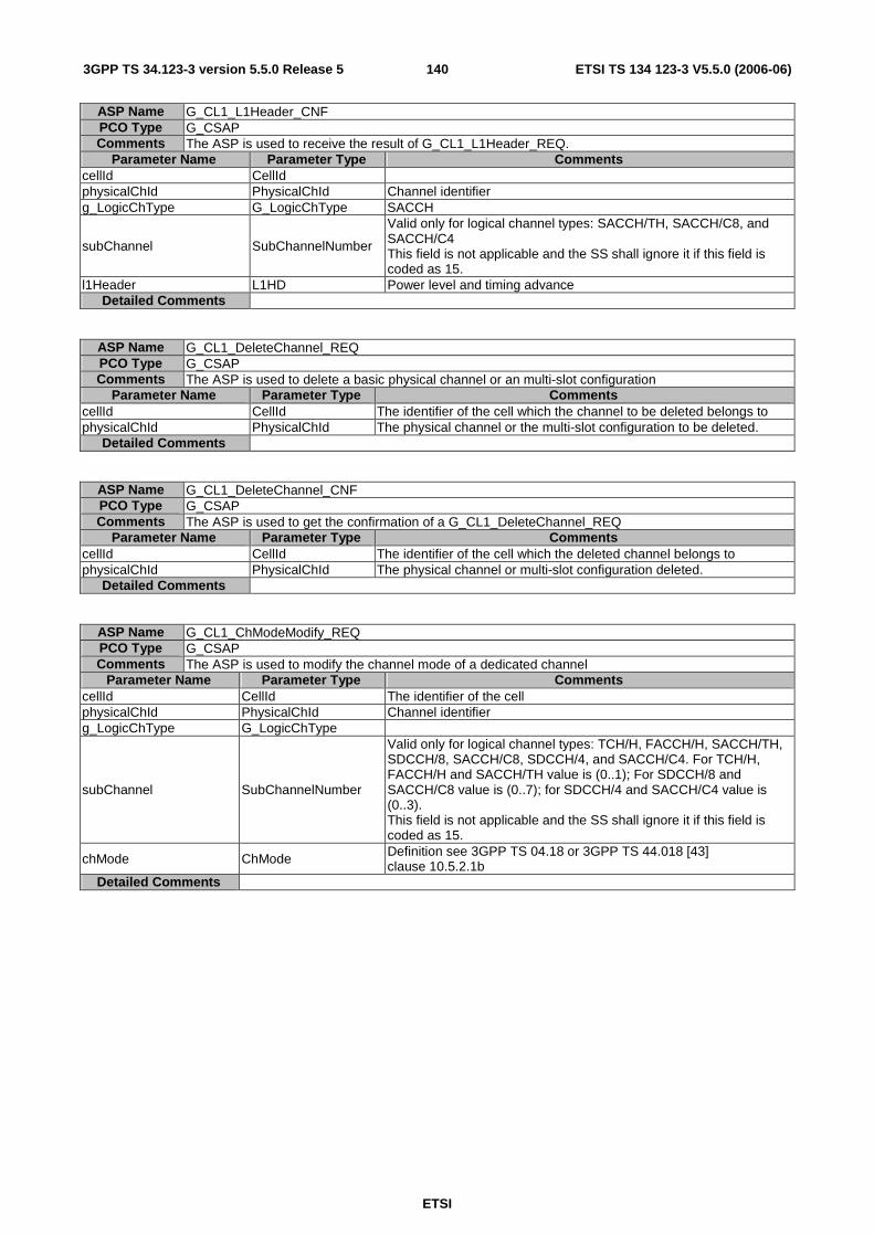
ETSI
ETSI TS 134 123-3 V5.5.0 (2006-06) 1403GPP TS 34.123-3 version 5.5.0 Release 5
ASP Name G_CL1_L1Header_CNF PCO Type G_CSAP Comments The ASP is used to receive the result of G_CL1_L1Header_REQ.
Parameter Name Parameter Type Comments cellId CellId physicalChId PhysicalChId Channel identifier g_LogicChType G_LogicChType SACCH
subChannel SubChannelNumber
Valid only for logical channel types: SACCH/TH, SACCH/C8, and SACCH/C4 This field is not applicable and the SS shall ignore it if this field is coded as 15.
l1Header L1HD Power level and timing advance Detailed Comments
ASP Name G_CL1_DeleteChannel_REQ PCO Type G_CSAP Comments The ASP is used to delete a basic physical channel or an multi-slot configuration
Parameter Name Parameter Type Comments cellId CellId The identifier of the cell which the channel to be deleted belongs to physicalChId PhysicalChId The physical channel or the multi-slot configuration to be deleted.
Detailed Comments
ASP Name G_CL1_DeleteChannel_CNF PCO Type G_CSAP Comments The ASP is used to get the confirmation of a G_CL1_DeleteChannel_REQ
Parameter Name Parameter Type Comments cellId CellId The identifier of the cell which the deleted channel belongs to physicalChId PhysicalChId The physical channel or multi-slot configuration deleted.
Detailed Comments
ASP Name G_CL1_ChModeModify_REQ PCO Type G_CSAP Comments The ASP is used to modify the channel mode of a dedicated channel
Parameter Name Parameter Type Comments cellId CellId The identifier of the cell physicalChId PhysicalChId Channel identifier g_LogicChType G_LogicChType
subChannel SubChannelNumber
Valid only for logical channel types: TCH/H, FACCH/H, SACCH/TH, SDCCH/8, SACCH/C8, SDCCH/4, and SACCH/C4. For TCH/H, FACCH/H and SACCH/TH value is (0..1); For SDCCH/8 and SACCH/C8 value is (0..7); for SDCCH/4 and SACCH/C4 value is (0..3). This field is not applicable and the SS shall ignore it if this field is coded as 15.
chMode ChMode Definition see 3GPP TS 04.18 or 3GPP TS 44.018 [43] clause 10.5.2.1b
Detailed Comments
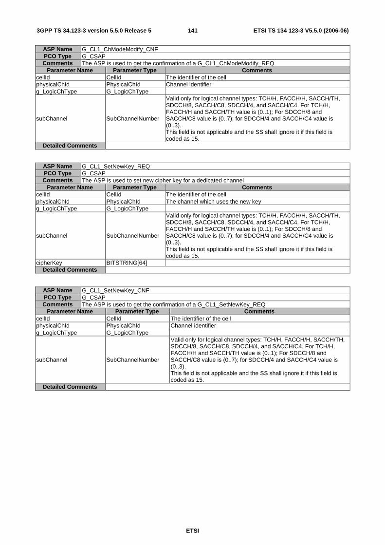
ETSI
ETSI TS 134 123-3 V5.5.0 (2006-06) 1413GPP TS 34.123-3 version 5.5.0 Release 5
ASP Name G_CL1_ChModeModify_CNF PCO Type G_CSAP Comments The ASP is used to get the confirmation of a G_CL1_ChModeModify_REQ
Parameter Name Parameter Type Comments cellId CellId The identifier of the cell physicalChId PhysicalChId Channel identifier g_LogicChType G_LogicChType
subChannel SubChannelNumber
Valid only for logical channel types: TCH/H, FACCH/H, SACCH/TH, SDCCH/8, SACCH/C8, SDCCH/4, and SACCH/C4. For TCH/H, FACCH/H and SACCH/TH value is (0..1); For SDCCH/8 and SACCH/C8 value is (0..7); for SDCCH/4 and SACCH/C4 value is (0..3). This field is not applicable and the SS shall ignore it if this field is coded as 15.
Detailed Comments
ASP Name G_CL1_SetNewKey_REQ PCO Type G_CSAP Comments The ASP is used to set new cipher key for a dedicated channel
Parameter Name Parameter Type Comments cellId CellId The identifier of the cell physicalChId PhysicalChId The channel which uses the new key g_LogicChType G_LogicChType
subChannel SubChannelNumber
Valid only for logical channel types: TCH/H, FACCH/H, SACCH/TH, SDCCH/8, SACCH/C8, SDCCH/4, and SACCH/C4. For TCH/H, FACCH/H and SACCH/TH value is (0..1); For SDCCH/8 and SACCH/C8 value is (0..7); for SDCCH/4 and SACCH/C4 value is (0..3). This field is not applicable and the SS shall ignore it if this field is coded as 15.
cipherKey BITSTRING[64] Detailed Comments
ASP Name G_CL1_SetNewKey_CNF PCO Type G_CSAP Comments The ASP is used to get the confirmation of a G_CL1_SetNewKey_REQ
Parameter Name Parameter Type Comments cellId CellId The identifier of the cell physicalChId PhysicalChId Channel identifier g_LogicChType G_LogicChType
subChannel SubChannelNumber
Valid only for logical channel types: TCH/H, FACCH/H, SACCH/TH, SDCCH/8, SACCH/C8, SDCCH/4, and SACCH/C4. For TCH/H, FACCH/H and SACCH/TH value is (0..1); For SDCCH/8 and SACCH/C8 value is (0..7); for SDCCH/4 and SACCH/C4 value is (0..3). This field is not applicable and the SS shall ignore it if this field is coded as 15.
Detailed Comments

ETSI
ETSI TS 134 123-3 V5.5.0 (2006-06) 1423GPP TS 34.123-3 version 5.5.0 Release 5
ASP Name G_CL1_CipherModeModify_REQ PCO Type G_CSAP Comments The ASP is used to modify cipher mode of a dedicated channel Parameter Name Parameter Type Comments
cellId CellId The identifier of the cell physicalChId PhysicalChId Channel identifier g_LogicChType G_LogicChType
subChannel SubChannelNumber
Valid only for logical channel types: TCH/H, FACCH/H, SACCH/TH, SDCCH/8, SACCH/C8, SDCCH/4, and SACCH/C4. For TCH/H, FACCH/H and SACCH/TH value is (0..1); For SDCCH/8 and SACCH/C8 value is (0..7); for SDCCH/4 and SACCH/C4 value is (0..3). This field is not applicable and the SS shall ignore it if this field is coded as 15.
cipherMode CipherModeSetting The new cipher mode. Definition see 3GPP TS 04.18 or 3GPP TS 44.018 [43] clause 10.5.2.9
Detailed Comments
ASP Name G_CL1_CipherModeModify_CNF PCO Type G_CSAP Comments The ASP is used to get the confirmation of a G_CL1_CipherModeModify_REQ Parameter Name Parameter Type Comments
cellId CellId The identifier of the cell physicalChId PhysicalChId Channel identifier g_LogicChType G_LogicChType
subChannel SubChannelNumber
Valid only for logical channel types: TCH/H, FACCH/H, SACCH/TH, SDCCH/8, SACCH/C8, SDCCH/4, and SACCH/C4. For TCH/H, FACCH/H and SACCH/TH value is (0..1); For SDCCH/8 and SACCH/C8 value is (0..7); for SDCCH/4 and SACCH/C4 value is (0..3). This field is not applicable and the SS shall ignore it if this field is coded as 15.
Detailed Comments
ASP Name G_CL1_ChangePowerLevel_REQ PCO Type G_CSAP Comments The ASP is used to change the transmission power level of a physical channel Parameter Name Parameter Type Comments
cellId CellId The identifier of the cell which the physical channel belongs to physicalChId PhysicalChId Channel using the new transmission power level txPower TX_Power The new transmission power level in dBµVemf()
Detailed Comments
ASP Name G_CL1_ChangePowerLevel_CNF PCO Type G_CSAP Comments The ASP is used to get the confirmation of a G_CL1_ChangePowerLevel_REQ
Parameter Name Parameter Type Comments cellId CellId The identifier of the cell physicalChId PhysicalChId The physical channel which uses the new transmission power level
Detailed Comments
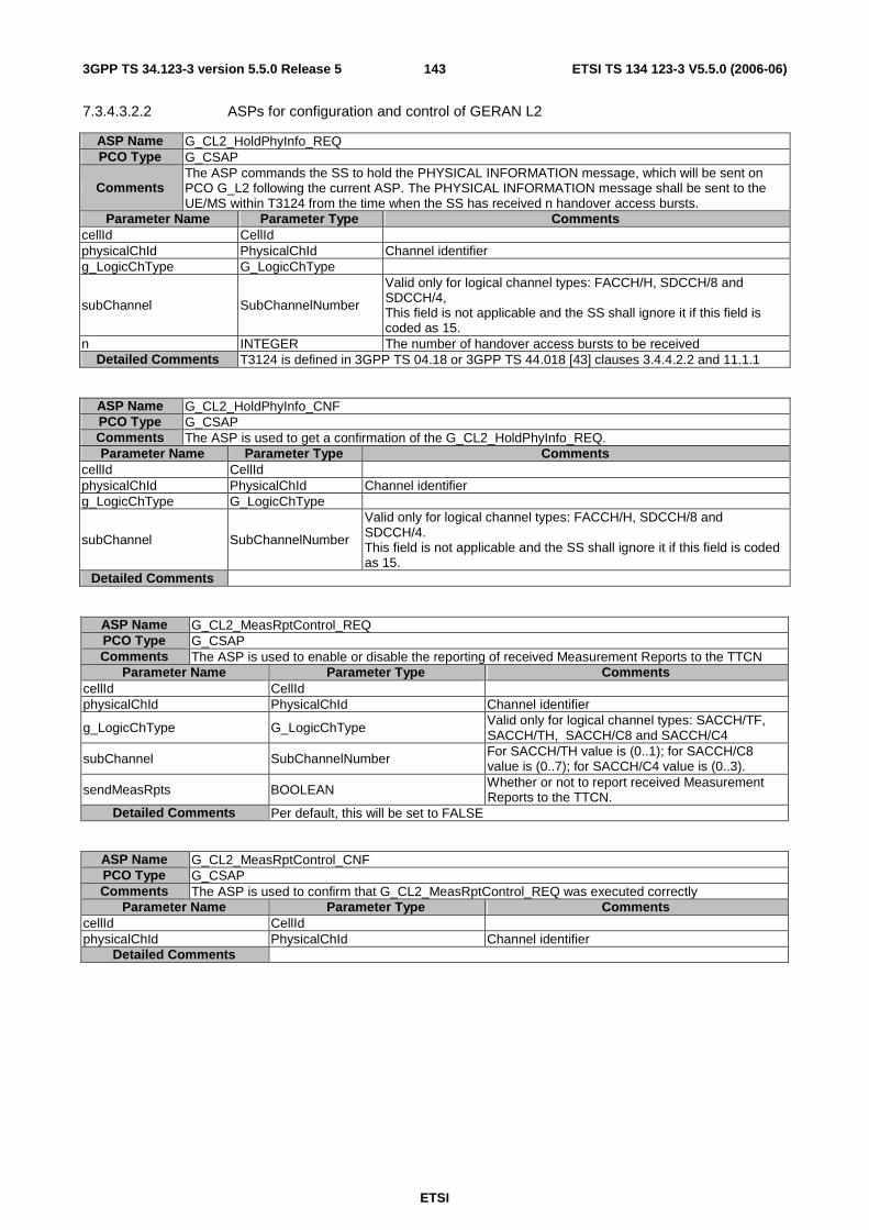
ETSI
ETSI TS 134 123-3 V5.5.0 (2006-06) 1433GPP TS 34.123-3 version 5.5.0 Release 5
7.3.4.3.2.2 ASPs for configuration and control of GERAN L2
ASP Name G_CL2_HoldPhyInfo_REQ PCO Type G_CSAP
Comments The ASP commands the SS to hold the PHYSICAL INFORMATION message, which will be sent on PCO G_L2 following the current ASP. The PHYSICAL INFORMATION message shall be sent to the UE/MS within T3124 from the time when the SS has received n handover access bursts.
Parameter Name Parameter Type Comments cellId CellId physicalChId PhysicalChId Channel identifier g_LogicChType G_LogicChType
subChannel SubChannelNumber
Valid only for logical channel types: FACCH/H, SDCCH/8 and SDCCH/4, This field is not applicable and the SS shall ignore it if this field is coded as 15.
n INTEGER The number of handover access bursts to be received Detailed Comments T3124 is defined in 3GPP TS 04.18 or 3GPP TS 44.018 [43] clauses 3.4.4.2.2 and 11.1.1
ASP Name G_CL2_HoldPhyInfo_CNF PCO Type G_CSAP Comments The ASP is used to get a confirmation of the G_CL2_HoldPhyInfo_REQ. Parameter Name Parameter Type Comments
cellId CellId physicalChId PhysicalChId Channel identifier g_LogicChType G_LogicChType
subChannel SubChannelNumber
Valid only for logical channel types: FACCH/H, SDCCH/8 and SDCCH/4. This field is not applicable and the SS shall ignore it if this field is coded as 15.
Detailed Comments
ASP Name G_CL2_MeasRptControl_REQ PCO Type G_CSAP Comments The ASP is used to enable or disable the reporting of received Measurement Reports to the TTCN
Parameter Name Parameter Type Comments cellId CellId physicalChId PhysicalChId Channel identifier
g_LogicChType G_LogicChType Valid only for logical channel types: SACCH/TF, SACCH/TH, SACCH/C8 and SACCH/C4
subChannel SubChannelNumber For SACCH/TH value is (0..1); for SACCH/C8 value is (0..7); for SACCH/C4 value is (0..3).
sendMeasRpts BOOLEAN Whether or not to report received Measurement Reports to the TTCN.
Detailed Comments Per default, this will be set to FALSE
ASP Name G_CL2_MeasRptControl_CNF PCO Type G_CSAP Comments The ASP is used to confirm that G_CL2_MeasRptControl_REQ was executed correctly
Parameter Name Parameter Type Comments cellId CellId physicalChId PhysicalChId Channel identifier
Detailed Comments
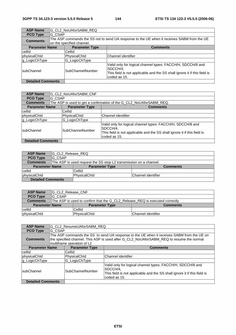
ETSI
ETSI TS 134 123-3 V5.5.0 (2006-06) 1443GPP TS 34.123-3 version 5.5.0 Release 5
ASP Name G_CL2_NoUAforSABM_REQ PCO Type G_CSAP
Comments The ASP commands the SS not to send UA response to the UE when it receives SABM from the UE on the specified channel.
Parameter Name Parameter Type Comments cellId CellId physicalChId PhysicalChId Channel identifier g_LogicChType G_LogicChType
subChannel SubChannelNumber
Valid only for logical channel types: FACCH/H, SDCCH/8 and SDCCH/4, This field is not applicable and the SS shall ignore it if this field is coded as 15.
Detailed Comments
ASP Name G_CL2_NoUAforSABM_CNF PCO Type G_CSAP Comments The ASP is used to get a confirmation of the G_CL2_NoUAforSABM_REQ. Parameter Name Parameter Type Comments
cellId CellId physicalChId PhysicalChId Channel identifier g_LogicChType G_LogicChType
subChannel SubChannelNumber
Valid only for logical channel types: FACCH/H, SDCCH/8 and SDCCH/4. This field is not applicable and the SS shall ignore it if this field is coded as 15.
Detailed Comments
ASP Name G_CL2_Release_REQ PCO Type G_CSAP Comments The ASP is used request the SS stop L2 transmission on a channel.
Parameter Name Parameter Type Comments cellId CellId physicalChId PhysicalChId Channel identifier
Detailed Comments
ASP Name G_CL2_Release_CNF PCO Type G_CSAP Comments The ASP is used to confirm that the G_CL2_Release_REQ is executed correctly
Parameter Name Parameter Type Comments cellId CellId physicalChId PhysicalChId Channel identifier
ASP Name G_CL2_ResumeUAforSABM_REQ PCO Type G_CSAP
Comments The ASP commands the SS to send UA response to the UE when it receives SABM from the UE on the specified channel. This ASP is used after G_CL2_NoUAforSABM_REQ to resume the normal multiframe operation of L2
Parameter Name Parameter Type Comments cellId CellId physicalChId PhysicalChId Channel identifier g_LogicChType G_LogicChType
subChannel SubChannelNumber
Valid only for logical channel types: FACCH/H, SDCCH/8 and SDCCH/4, This field is not applicable and the SS shall ignore it if this field is coded as 15.
Detailed Comments

ETSI
ETSI TS 134 123-3 V5.5.0 (2006-06) 1453GPP TS 34.123-3 version 5.5.0 Release 5
ASP Name G_CL2_ResumeUAforSABM_CNF PCO Type G_CSAP Comments The ASP is used to get a confirmation of the G_CL2_ResumeUAforSABM_REQ.
Parameter Name Parameter Type Comments cellId CellId physicalChId PhysicalChId Channel identifier g_LogicChType G_LogicChType
subChannel SubChannelNumber
Valid only for logical channel types: FACCH/H, SDCCH/8 and SDCCH/4. This field is not applicable and the SS shall ignore it if this field is coded as 15.
Detailed Comments
7.3.4.3.2.3 ASPs for configuration and control of GERAN RLC/MAC
ASP Name G_CRLC_CreateRLC_MAC_REQ PCO Type G_CSAP Comments The ASP is used to create a RLC/MAC entity in GERAN RLC/MAC emulation module.
Parameter Name Parameter Type Comments cellId CellId The identifier of the cell
Detailed Comments
One RLC/MAC entity per cell can exist, cellId will be used for couping LLC layer module to the RLC/MAC emulation module.. The packet channel description given in the ChannelSpecificInfo of G_CL1_CreateBasicPhyCh_REQ shall be used to configure this layer. This ASP shall be called after the G_CL1_CreateBasicPhyCh_REQ ASP.
ASP Name G_CRLC_CreateRLC_MAC_CNF PCO Type G_CSAP Comments The ASP is used to confirm the G_CRLC_CreateRLC_MAC_REQ
Parameter Name Parameter Type Comments cellId CellId The identifier of the cell
Detailed Comments
ASP Name G_CRLC_DeleteRLC_MAC_REQ PCO Type G_CSAP Comments The ASP is used to delete a RLC/MAC entity in GERAN emulation module.
Parameter Name Parameter Type Comments cellId CellId The identifier of the cell
Detailed Comments This ASP is used to release any resource used for the RLC/MAC emulation entity in the SS.
ASP Name G_CRLC_DeleteRLC_MAC_CNF PCO Type G_CSAP Comments The ASP is used to confirm the G_CRLC_CreateRLC_MAC_REQ
Parameter Name Parameter Type Comments cellId CellId The identifier of the cell
Detailed Comments

ETSI
ETSI TS 134 123-3 V5.5.0 (2006-06) 1463GPP TS 34.123-3 version 5.5.0 Release 5
ASP Name G_CRLC_UL_TBF_Config_REQ PCO Type G_CSAP Comments The ASP is used to configure a TBF used for uplink packet data transfer
Parameter Name Parameter Type Comments cellId CellId tFI TFI
tBF_Mode BITSTRING[1] 0 - GPRS; 1 - EGPRS
channelCoding ChannelCoding
tLLI_BlockChannelCoding BITSTRING[1] 0 - CS-1 or MCS-1(EGPRS); 1 - same as channelCoding
rLC_Mode BITSTRING[1] 0 - acknowledged mode; 1 - unacknowledged mode
startingTime RFN This field is not applicable and the SS shall ignore it if the field t2 of rfn is coded as '11111'B.
uSF_Rate INTEGER
This parameter controls the speed of the UL TBF transferring data blocks by controlling the USF rate: 1---> implementation dependent. TTCN does not specify the USF generating rate; 2---> 10 USF's per second; 3---> 5 USF's per second; 4---> 1 USF per second; 5---> 1 USF per 2 seconds; 6---> 1 USF per 3 seconds; 7---> 1 USF per 4 seconds.
dynamicAllocation dynamicAllocation dynamic allocation and other parameters.
Detailed Comments
For GPRS channel coding can be: CS-1, CS-2, CS-3 and CS-4; For EGPRS channel coding can be : MCS-1, MCS-2, MCS-3, MCS-4, MCS-5, MCS-6, MCS-7, MCS-8, MCS-9, MCS-5-7 and MCS-6-9. Due to one cell currently has only one RLC/MAC emulation module, this ASP does not contain RLC/MAC identity parameter to indicate which RLC/MAC emulation module this TBF is established for, instead, the parameter cellId implicitly indicates the RLC/MAC module, which is created by G_CRLC_CreateRLC_MAC_REQ in the cell. The higher layer (LLC emulation module) uses rLC/MAC_MappingInfo (with type of CellId) to address the RLC/MAC emulation module to which it connects
ASP Name G_CRLC_UL_TBF_Config_CNF PCO Type G_CSAP Comments The ASP is used to get the confirmation of a G_CRLC_UL_TBF_Config_REQ
Parameter Name Parameter Type Comments cellId CellId tFI TFI
Detailed Comments
Type Name ChannelCoding Type Definition INTEGER Type Encoding
Comments
1 - CS-1; 2 - CS-2; 3 - CS-3; 4 -- CS-4; 5 - MCS-1; 6 - MCS-2; 7 - MCS-3; 8 - MCS-4; 9 - MCS-5; 10 - MCS-6; 11 - MCS-7; 12 - MCS-8; 13 - MCS-9; 14 - MCS-5-7; 15 - MCS-6-9
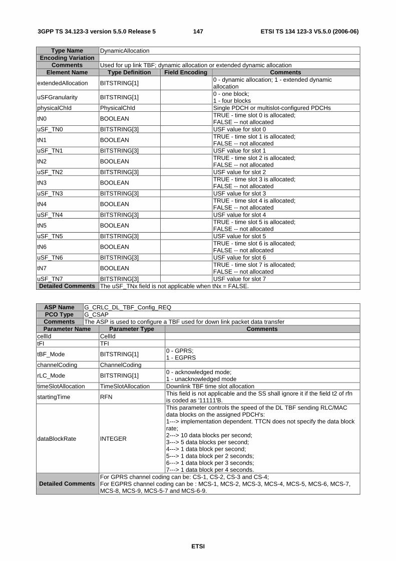
ETSI
ETSI TS 134 123-3 V5.5.0 (2006-06) 1473GPP TS 34.123-3 version 5.5.0 Release 5
Type Name DynamicAllocation Encoding Variation
Comments Used for up link TBF; dynamic allocation or extended dynamic allocation Element Name Type Definition Field Encoding Comments
extendedAllocation BITSTRING[1] 0 - dynamic allocation; 1 - extended dynamic allocation
uSFGranularity BITSTRING[1] 0 - one block; 1 - four blocks
physicalChId PhysicalChId Single PDCH or multislot-configured PDCHs
tN0 BOOLEAN TRUE - time slot 0 is allocated; FALSE -- not allocated
uSF_TN0 BITSTRING[3] USF value for slot 0
tN1 BOOLEAN TRUE - time slot 1 is allocated; FALSE -- not allocated
uSF_TN1 BITSTRING[3] USF value for slot 1
tN2 BOOLEAN TRUE - time slot 2 is allocated; FALSE -- not allocated
uSF_TN2 BITSTRING[3] USF value for slot 2
tN3 BOOLEAN TRUE - time slot 3 is allocated; FALSE -- not allocated
uSF_TN3 BITSTRING[3] USF value for slot 3
tN4 BOOLEAN TRUE - time slot 4 is allocated; FALSE -- not allocated
uSF_TN4 BITSTRING[3] USF value for slot 4
tN5 BOOLEAN TRUE - time slot 5 is allocated; FALSE -- not allocated
uSF_TN5 BITSTRING[3] USF value for slot 5
tN6 BOOLEAN TRUE - time slot 6 is allocated; FALSE -- not allocated
uSF_TN6 BITSTRING[3] USF value for slot 6
tN7 BOOLEAN TRUE - time slot 7 is allocated; FALSE -- not allocated
uSF_TN7 BITSTRING[3] USF value for slot 7 Detailed Comments The uSF_TNx field is not applicable when tNx = FALSE.
ASP Name G_CRLC_DL_TBF_Config_REQ PCO Type G_CSAP Comments The ASP is used to configure a TBF used for down link packet data transfer Parameter Name Parameter Type Comments
cellId CellId tFI TFI
tBF_Mode BITSTRING[1] 0 - GPRS; 1 - EGPRS
channelCoding ChannelCoding
rLC_Mode BITSTRING[1] 0 - acknowledged mode; 1 - unacknowledged mode
timeSlotAllocation TimeSlotAllocation Downlink TBF time slot allocation
startingTime RFN This field is not applicable and the SS shall ignore it if the field t2 of rfn is coded as '11111'B.
dataBlockRate INTEGER
This parameter controls the speed of the DL TBF sending RLC/MAC data blocks on the assigned PDCH's: 1---> implementation dependent. TTCN does not specify the data block rate; 2---> 10 data blocks per second; 3---> 5 data blocks per second; 4---> 1 data block per second; 5---> 1 data block per 2 seconds; 6---> 1 data block per 3 seconds; 7---> 1 data block per 4 seconds.
Detailed Comments For GPRS channel coding can be: CS-1, CS-2, CS-3 and CS-4; For EGPRS channel coding can be : MCS-1, MCS-2, MCS-3, MCS-4, MCS-5, MCS-6, MCS-7, MCS-8, MCS-9, MCS-5-7 and MCS-6-9.

ETSI
ETSI TS 134 123-3 V5.5.0 (2006-06) 1483GPP TS 34.123-3 version 5.5.0 Release 5
ASP Name G_CRLC_DL_TBF_Config_CNF PCO Type G_CSAP Comments The ASP is used to get the confirmation of a G_CRLC_DL_TBF_Config_REQ
Parameter Name Parameter Type Comments cellId CellId tFI TFI
Detailed Comments
Type Name TimeSlotAllocation Encoding Variation
Comments Used for downlink and up link TBF Element Name Type Definition Field Encoding Comments
physicalChId PhysicalChId single PDCH or multislot-configured PDCHs
tN0 BOOLEAN Timeslot 0; TRUE - allocated; FALSE - not allocated.
tN1 BOOLEAN Timeslot 1; TRUE - allocated; FALSE - not allocated.
tN2 BOOLEAN Timeslot 2; TRUE - allocated; FALSE - not allocated.
tN3 BOOLEAN Timeslot 3; TRUE - allocated; FALSE - not allocated.
tN4 BOOLEAN Timeslot 4; TRUE - allocated; FALSE - not allocated.
tN5 BOOLEAN Timeslot 5; TRUE - allocated; FALSE - not allocated.
tN6 BOOLEAN Timeslot 6; TRUE - allocated; FALSE - not allocated.
tN7 BOOLEAN Timeslot 7; TRUE - allocated; FALSE - not allocated.
Detailed Comments
7.3.4.3.2.4 ASPs for configuration and control of GERAN LLC
ASP Name G_CLLC_CreateLLE_REQ PCO Type G_CSAP
Comments The ASP is used to create an LLE (LLC Entity) in GERAN emulation part of the SS and connects the created LLE to the RLC/MAC emulation module pointed by rLC/MAC_MappingInfo..
Parameter Name Parameter Type Comments lLMEId LLMEId Logical Layer Management Entity Id
rLC/MAC_MappingInfo CellId This parameter indicates the RLC/MAC emulation module in the cell, not the cell itself.
Detailed Comments The RLC/MAC emulation module needs to be created prior to this ASP by G_CRLC_CreateRLC_MAC_REQ ASP.
ASP Name G_CLLC_CreateLLE_CNF PCO Type G_CSAP Comments The ASP is used to confirm the G_CLLC_CreateLLE_REQ
Parameter Name Parameter Type Comments
lLMEId LLMEId The identifier of the cell Logical Layer Management Entity Id
Detailed Comments

ETSI
ETSI TS 134 123-3 V5.5.0 (2006-06) 1493GPP TS 34.123-3 version 5.5.0 Release 5
ASP Name G_CLLC_DeleteLLE_REQ PCO Type G_CSAP Comments The ASP is used to delete an LLE (LLC Entity) in GERAN LLC emulation module.
Parameter Name Parameter Type Comments lLMEId LLMEId Logical Layer Management Entity Id
Detailed Comments
ASP Name G_CLLC_DeleteLLE_CNF PCO Type G_CSAP Comments The ASP is used to confirm the G_CLLC_DeleteLLE_REQ
Parameter Name Parameter Type Comments lLMEId LLMEId Logical Layer Management Entity Id
Detailed Comments
ASP Name G_CLLC_Assign_REQ PCO Type G_CSAP
Comments The ASP is used to assign, change, or unassign the TLLI, the ciphering key (Kc) and the ciphering algorithm of GERAN LLC emulation module.
Parameter Name Parameter Type Comments lLMEId LLMEId Logical Layer Management Entity Id oldTLLI TLLI OCTETSTRING[4] newTLLI TLLI cipherKey BITSTRING[64] cipherAlgorithm GPRS_CipherAlg BITSTRING[3], see 3GPP TS 24.008 [9] clause 10.5.5.3
Detailed Comments
This ASP is used to assign, change, or unassign the TLLI, the ciphering key (Kc) and the ciphering algorithm. 1. The oldTLLI and newTLLI parameters shall be interpreted as follows:
- If oldTLLI = all 1's and newTLLI ≠ all 1's then newTLLI is assigned and used when (re-)transmitting LLC frames. If an oldTLLI ≠ all 1's was assigned to the LLME, then oldTLLI is unassigned. Only newTLLI is accepted when received from the peer. It shall be treated as a TLLI change. If oldTLLI = all 1's was assigned to the LLME, then this shall be treated as a TLLI assignment, and this ASP shall be the first ASP sent to the SS in order to enable LLC to process requests from layer 3.
- If oldTLLI ≠ all 1's and newTLLI ≠ all 1's then oldTLLI and newTLLI are assigned, and newTLLI shall be used when (re-)transmitting LLC frames. Both oldTLLI and newTLLI shall be accepted when received from the peer. It shall be treated as a TLLI change.
- If oldTLLI ≠ all 1's and newTLLI = all 1's then oldTLLI shall be unassigned. It shall be treated as a TLLI unassignment, and this ASP shall be the last ASP sent to the SS in order to disable LLC to not process requests from layer 3 any longer.
2. Kc and Ciphering Algorithm are associated with newTLLI (and with oldTLLI if assigned): - If Ciphering Algorithm indicates no ciphering, then the ciphering function shall be disabled. - Otherwise, the ciphering function shall be enabled. If a Ciphering Algorithm was already associated with newTLLI or oldTLLI, then the new Kc shall replace the previous Kc, and Ciphering Algorithm shall replace the previous algorithm selection. All I frames, and UI frames with the E bit set to 1, shall use the new Kc and algorithm for ciphering. All unacknowledged I frames shall be ciphered using the new Kc and algorithm before retransmission. As an implementation option, the previous Kc and algorithm may be used to decipher received frames.
ASP Name G_CLLC_Assign_CNF PCO Type G_CSAP Comments the ASP is used to get confirmation of G_CLLC_Assign_REQ
Parameter Name Parameter Type Comments lLMEId LLMEId Logical Layer Management Entity Id
Detailed Comments
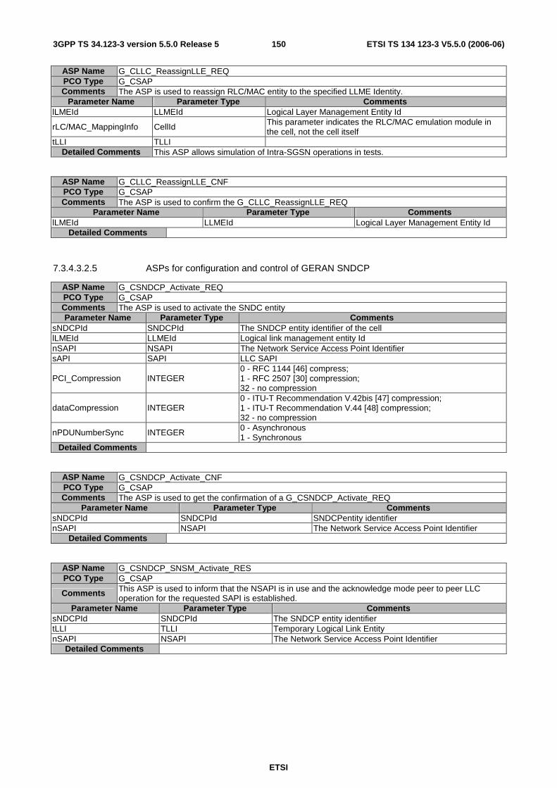
ETSI
ETSI TS 134 123-3 V5.5.0 (2006-06) 1503GPP TS 34.123-3 version 5.5.0 Release 5
ASP Name G_CLLC_ReassignLLE_REQ PCO Type G_CSAP Comments The ASP is used to reassign RLC/MAC entity to the specified LLME Identity.
Parameter Name Parameter Type Comments lLMEId LLMEId Logical Layer Management Entity Id
rLC/MAC_MappingInfo CellId This parameter indicates the RLC/MAC emulation module in the cell, not the cell itself
tLLI TLLI Detailed Comments This ASP allows simulation of Intra-SGSN operations in tests.
ASP Name G_CLLC_ReassignLLE_CNF PCO Type G_CSAP Comments The ASP is used to confirm the G_CLLC_ReassignLLE_REQ
Parameter Name Parameter Type Comments lLMEId LLMEId Logical Layer Management Entity Id
Detailed Comments
7.3.4.3.2.5 ASPs for configuration and control of GERAN SNDCP
ASP Name G_CSNDCP_Activate_REQ PCO Type G_CSAP Comments The ASP is used to activate the SNDC entity Parameter Name Parameter Type Comments
sNDCPId SNDCPId The SNDCP entity identifier of the cell lLMEId LLMEId Logical link management entity Id nSAPI NSAPI The Network Service Access Point Identifier sAPI SAPI LLC SAPI
PCI_Compression INTEGER 0 - RFC 1144 [46] compress; 1 - RFC 2507 [30] compression; 32 - no compression
dataCompression INTEGER 0 - ITU-T Recommendation V.42bis [47] compression; 1 - ITU-T Recommendation V.44 [48] compression; 32 - no compression
nPDUNumberSync INTEGER 0 - Asynchronous 1 - Synchronous
Detailed Comments
ASP Name G_CSNDCP_Activate_CNF PCO Type G_CSAP Comments The ASP is used to get the confirmation of a G_CSNDCP_Activate_REQ
Parameter Name Parameter Type Comments sNDCPId SNDCPId SNDCPentity identifier nSAPI NSAPI The Network Service Access Point Identifier
Detailed Comments
ASP Name G_CSNDCP_SNSM_Activate_RES PCO Type G_CSAP
Comments This ASP is used to inform that the NSAPI is in use and the acknowledge mode peer to peer LLC operation for the requested SAPI is established.
Parameter Name Parameter Type Comments sNDCPId SNDCPId The SNDCP entity identifier tLLI TLLI Temporary Logical Link Entity nSAPI NSAPI The Network Service Access Point Identifier
Detailed Comments
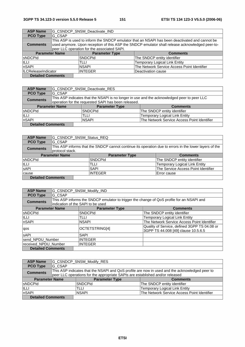
ETSI
ETSI TS 134 123-3 V5.5.0 (2006-06) 1513GPP TS 34.123-3 version 5.5.0 Release 5
ASP Name G_CSNDCP_SNSM_Deactivate_IND PCO Type G_CSAP
Comments This ASP is used to inform the SNDCP emulator that an NSAPI has been deactivated and cannot be used anymore. Upon reception of this ASP the SNDCP emulator shall release acknowledged peer-to-peer LLC operation for the associated SAPI.
Parameter Name Parameter Type Comments sNDCPId SNDCPId The SNDCP entity identifier tLLI TLLI Temporary Logical Link Entity nSAPI NSAPI The Network Service Access Point Identifier lLCReleaseIndicator INTEGER Deactivation cause
Detailed Comments
ASP Name G_CSNDCP_SNSM_Deactivate_RES PCO Type G_CSAP
Comments This ASP indicates that the NSAPI is no longer in use and the acknowledged peer to peer LLC operation for the requested SAPI has been released.
Parameter Name Parameter Type Comments sNDCPId SNDCPId The SNDCP entity identifier tLLI TLLI Temporary Logical Link Entity nSAPI NSAPI The Network Service Access Point Identifier
Detailed Comments
ASP Name G_CSNDCP_SNSM_Status_REQ PCO Type G_CSAP
Comments This ASP informs that the SNDCP cannot continue its operation due to errors in the lower layers of the protocol stack.
Parameter Name Parameter Type Comments sNDCPId SNDCPId The SNDCP entity identifier tLLI TLLI Temporary Logical Link Entity sAPI SAPI The Service Access Point Identifier cause INTEGER Error cause
Detailed Comments
ASP Name G_CSNDCP_SNSM_Modify_IND PCO Type G_CSAP
Comments This ASP informs the SNDCP emulator to trigger the change of QoS profile for an NSAPI and indication of the SAPI to be used
Parameter Name Parameter Type Comments sNDCPId SNDCPId The SNDCP entity identifier tLLI TLLI Temporary Logical Link Entity nSAPI NSAPI The Network Service Access Point Identifier
qos OCTETSTRING[4] Quality of Service, defined 3GPP TS 04.08 or 3GPP TS 44.008 [49] clause 10.5.6.5
sAPI SAPI send_NPDU_Number INTEGER received_NPDU_Number INTEGER
Detailed Comments
ASP Name G_CSNDCP_SNSM_Modify_RES PCO Type G_CSAP
Comments This ASP indicates that the NSAPI and QoS profile are now in used and the acknowledged peer to peer LLC operations for the appropriate SAPIs are established and/or released
Parameter Name Parameter Type Comments sNDCPId SNDCPId The SNDCP entity identifier tLLI TLLI Temporary Logical Link Entity nSAPI NSAPI The Network Service Access Point Identifier
Detailed Comments

ETSI
ETSI TS 134 123-3 V5.5.0 (2006-06) 1523GPP TS 34.123-3 version 5.5.0 Release 5
7.3.5 A-GPS Upper tester, PCO and ASP definitions
7.3.5.1 Upper tester
In order to perform A-GPS test, an Upper Tester is defined to have two basic functional unites:
- Satellite simulator generating and broadcasting satellite signals,
- Assistance data source storing the data simulating a number of pre-defined GPS test scenarios.
Under the TTCN command, the upper tester loads a pre-defined or re-loads another pre-defined GPS test scenario to the satellite simulator. The generated satellite signals shall simulate a sufficient number satellites. The signal shall be sufficiently strong, in order to enable the UE to do the positioning measurement.
The SS also sends the GPS assistance data to the UE through RRC signalling to facilitate the UE acquiring and tracking satellites. Such assistance data shall be consistent to within +/- 2 seconds with the satellite signals generated.
The assistance data source shall provide the assistance data consistent to + 1 /- 0 second with the GPS test scenario currently running in the satellite simulator (i.e. the data shall be up to 1 second in advance of the scenario); this allows for a further 2 seconds of latency in the SS.
7.3.5.2 SV PCO
The upper tester has an ASP interface through a PCO in type of SatS PCO defined in the table.
PCO Type Declarations PCO Type SatS
Role UT Comments PCO type used for the Satellite Simulator and the assistance data source in the
upper tester
PCO Declarations PCO Name SV PCO Type SatS
Role UT Comments Carry control, configuration and GPS assistance data to/from satellite simulator
and assistance data source in the upper tester
7.3.5.3 A-GPS Primitives
The primitives at SV PCO are used to
- load a pre-defined GPS test scenario into the satellite simulator;
- start or stop generating and broadcasting satellite signals from the satellite simulator;
- retrieve the GPS assistance data from assistance data source, the table below is the summary of these primitives.
Primitive Parameters Use Satellite_StartStop_REQ Mode: start or stop Start or stop generating satellite signals in the
satellite simulator. Satellite_StartStop_CNF Null Confirm the Satellite_StartStop_Req. Load_GPS_Scenario_ REQ GPS test scenario number Requests to load a pre-defined GPS test
scenario into the satellite simulator Load_GPS_Scenario_ CNF Null Confirm the load_GPS_Scenario_Req Retri_GPS_AssistanceData_REQ Indication of which assistance
data elements to be retrieved Request the assistance data source to provide the next (in time) valid GPS assistance data elements.
Retri_GPS_AssistanceData_CNF GPS assistance data elements Return the GPS assistance data retrieved

ETSI
ETSI TS 134 123-3 V5.5.0 (2006-06) 1533GPP TS 34.123-3 version 5.5.0 Release 5
7.3.5.3.1 Control ASP Type Definition
ASN.1 ASP Type Definition Type Name Satellite_StartStop_CNF PCO Type SatS Comment To confirm successful of Satellite_StartStop_REQ
Type Definition SEQUENCE { confirm NULL }
ASN.1 ASP Type Definition Type Name Satellite_StartStop_REQ PCO Type SatS Comment To start or stop generating satellite signals in the satellite simulator
"start" starts broadcasting satellite signals; "stop" stops broadcasting satellite signals If used for start (0), this ASP shall be called 2 s. after the ASP Load_GPS_Scenario_REQ for loading or reloading a pre-defined GPS test scenario.
Type Definition SEQUENCE { satelliteSignals ENUMERATED {startSatSignal (0), stopSatSignal (1)} }
7.3.5.3.2 Data ASP Type Definition
ASN.1 ASP Type Definition Type Name Load_GPS_Scenario_CNF PCO Type SatS Comment To confirm the Load_GPS_Scenario_REQ
Type Definition SEQUENCE { dummy NULL }
ASN.1 ASP Type Definition Type Name Load_GPS_Scenario_REQ PCO Type SatS Comment To request the upper tester to load the required pre-defined GPS test scenario.
Type Definition SEQUENCE { gps_Scenario INTEGER(0..31)}
ASN.1 ASP Type Definition Type Name Retri_GPS_AssistanceData_CNF PCO Type SatS Comment To return the next valid GPS assistance data elements as requested in the
Retri_GPS_AssistanceData_REQ. The returned GPS assistance data (all or part) will be used as assistance data sent to UE in RRC messages for A-GPS positioning.
Type Definition SEQUENCE { assistanceData UE_Positioning_GPS_AssistanceData }
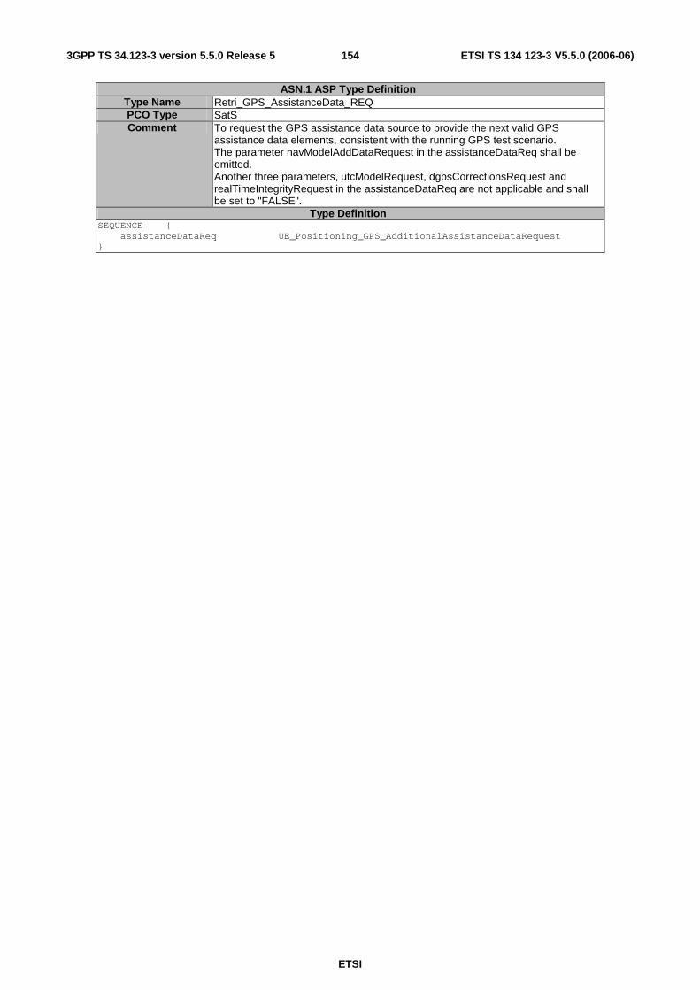
ETSI
ETSI TS 134 123-3 V5.5.0 (2006-06) 1543GPP TS 34.123-3 version 5.5.0 Release 5
ASN.1 ASP Type Definition Type Name Retri_GPS_AssistanceData_REQ PCO Type SatS Comment To request the GPS assistance data source to provide the next valid GPS
assistance data elements, consistent with the running GPS test scenario. The parameter navModelAddDataRequest in the assistanceDataReq shall be omitted. Another three parameters, utcModelRequest, dgpsCorrectionsRequest and realTimeIntegrityRequest in the assistanceDataReq are not applicable and shall be set to "FALSE".
Type Definition SEQUENCE { assistanceDataReq UE_Positioning_GPS_AdditionalAssistanceDataRequest }
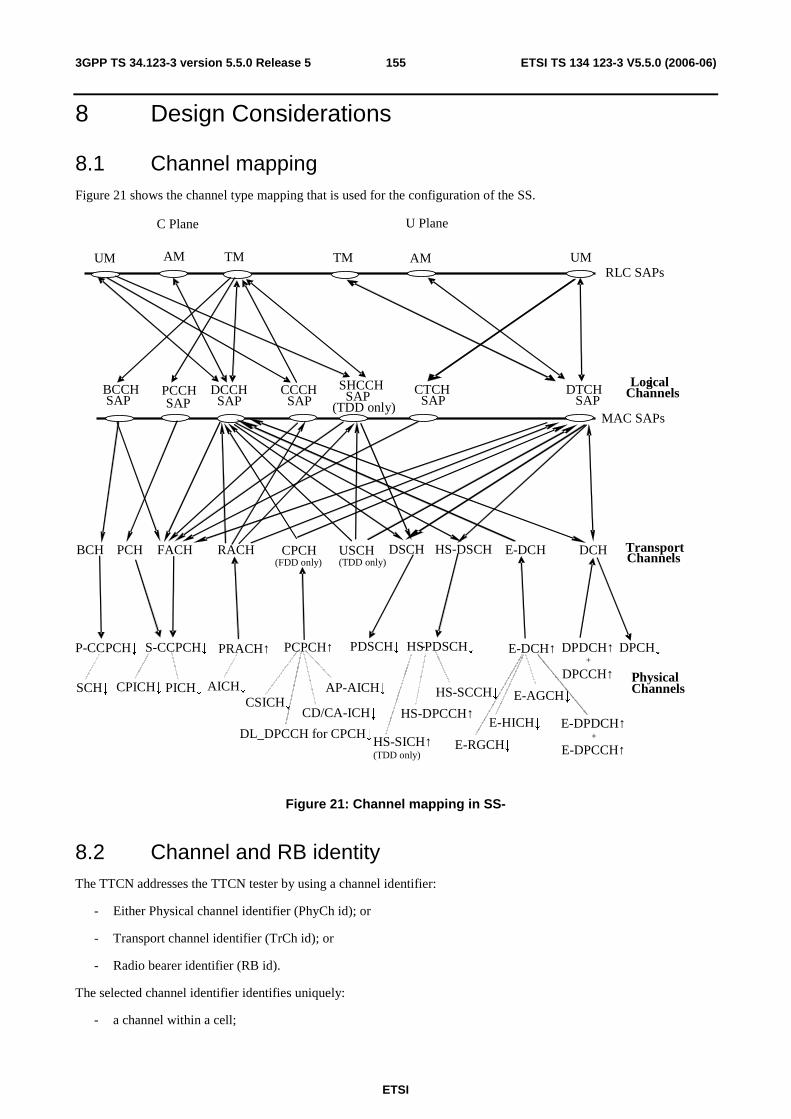
ETSI
ETSI TS 134 123-3 V5.5.0 (2006-06) 1553GPP TS 34.123-3 version 5.5.0 Release 5
8 Design Considerations
8.1 Channel mapping Figure 21 shows the channel type mapping that is used for the configuration of the SS.
BCH PCH DSCH FACH RACH
BCCH SAP
DCCH SAP
CCCH SAP
PCCH SAP
DTCH SAP
USCH (TDD only)
CPCH (FDD only)
CTCH SAP
SHCCH SAP (TDD only)
PRACH↑
CPICH↓
PCPCH↑
AP-AICH↓
P-CCPCH↓
SCH↓
S-CCPCH↓
AICH↓
PDSCH↓
PICH↓ CSICH↓
CD/CA-ICH↓
Physical Channels
Logical Channels
RLC SAPs UM AM TM TM AM UM
C Plane U Plane
DL_DPCCH for CPCH↓
HS- DSCH
HS - PDSCH↓
HS-SCCH↓
HS-DPCCH↑
E-DCH
MAC SAPs
DPCH↓ DPDCH↑ +
DPCCH↑
Transport Channels
DCH
E-DCH↑
E-DPDCH↑ +
E-DPCCH↑
E-AGCH↓
HS-SICH↑(TDD only)
E-RGCH↓
E-HICH↓
Figure 21: Channel mapping in SS-
8.2 Channel and RB identity The TTCN addresses the TTCN tester by using a channel identifier:
- Either Physical channel identifier (PhyCh id); or
- Transport channel identifier (TrCh id); or
- Radio bearer identifier (RB id).
The selected channel identifier identifies uniquely:
- a channel within a cell;
ETSI
ETSI TS 134 123-3 V5.5.0 (2006-06) 1563GPP TS 34.123-3 version 5.5.0 Release 5
- a total path of the address in the lower layers concerned.
Having taken out the cell id and PCO id (AM, UM and TM), a complete address, as RoutingInfo in the RRC ASP definition, should have at least five fields, CN domain id, RB id, LogCH id, TrCH id and PhyCH id. For simplified application of CHOICE of the routing information, a TTCN writer must carefully follow a number of rules assigning the channel identifiers.
General requirements:
- a structured scheme of planning all channel identifiers assigned;
- the scheme shall meet the requirements for all test cases in 3GPP TS 34.123-1 [1] including TDD channels;
- the scheme can apply to all radio bearer configurations in 3GPP TS 34.108 [3], clause 6.10;
- a clear multiplex mapping between a PhyCH id to TrCH ids and a TrCH id to LogCH ids, RB ids is needed.
Requirements on identification of RB in a test case:
- unique identification of the individual SRBs;
- unique identification of the individual sub-flows of a RABs in CS and PS domain.;
- an assigned RB id can represent UL and DL.
Requirements on identification of Logical Channel in a test case:
- it is an instance number of the individual logical channel; and
- uniquely identifies among all the Logical Channel mapped onto a Transport Channel.
Requirements on identification of Transport Channel in a test case:
- unique identification of the individual Transport Channel;
- assign different identities for UL and DL of a same Transport Channel type;
- the order of the Transport Channel id assigned in a cell shall follow the TFCS definitions in the 3GPP TS 34.108 [3], clause 6.10.
EXAMPLE: Transport Channel ids are assigned in the ascending order for (RABsubflow#1, RABsubflow#2, RABsubflow#3, 64kRAB, DCCH).
Requirements on identification of Physical Channel in a test case:
- unique identification of the individual Physical Channel;
- assign different identities for UL and DL of a same Physical Channel type;
- each S-CCPCH or PRACH has a unique identifier;
- for 2 Mbps PS data radio link (in case of demux of a Transport Channel), three DPCH are needed for high-speed data. A single Physical Channel id is assigned to a bundle of the three physical channels.
Table 31 shows which type of channel identity is chosen for the individual primitives. In table 31, the ASN.1 primitives use a CHOICE type for channel identity, while TTCN primitives use an explicit channel identity.
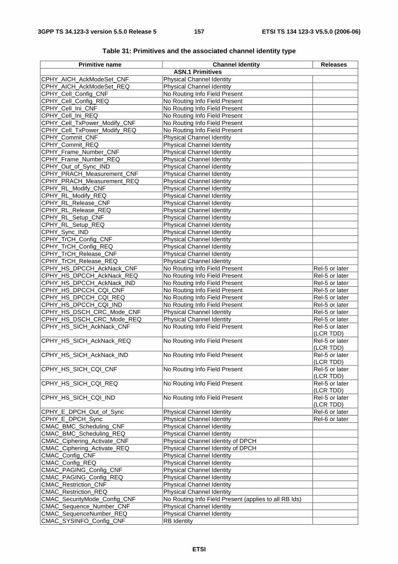
ETSI
ETSI TS 134 123-3 V5.5.0 (2006-06) 1573GPP TS 34.123-3 version 5.5.0 Release 5
Table 31: Primitives and the associated channel identity type
Primitive name Channel Identity Releases ASN.1 Primitives
CPHY_AICH_AckModeSet_CNF Physical Channel Identity CPHY_AICH_AckModeSet_REQ Physical Channel Identity CPHY_Cell_Config_CNF No Routing Info Field Present CPHY_Cell_Config_REQ No Routing Info Field Present CPHY_Cell_Ini_CNF No Routing Info Field Present CPHY_Cell_Ini_REQ No Routing Info Field Present CPHY_Cell_TxPower_Modify_CNF No Routing Info Field Present CPHY_Cell_TxPower_Modify_REQ No Routing Info Field Present CPHY_Commit_CNF Physical Channel Identity CPHY_Commit_REQ Physical Channel Identity CPHY_Frame_Number_CNF Physical Channel Identity CPHY_Frame_Number_REQ Physical Channel Identity CPHY_Out_of_Sync_IND Physical Channel Identity CPHY_PRACH_Measurement_CNF Physical Channel Identity CPHY_PRACH_Measurement_REQ Physical Channel Identity CPHY_RL_Modify_CNF Physical Channel Identity CPHY_RL_Modify_REQ Physical Channel Identity CPHY_RL_Release_CNF Physical Channel Identity CPHY_RL_Release_REQ Physical Channel Identity CPHY_RL_Setup_CNF Physical Channel Identity CPHY_RL_Setup_REQ Physical Channel Identity CPHY_Sync_IND Physical Channel Identity CPHY_TrCH_Config_CNF Physical Channel Identity CPHY_TrCH_Config_REQ Physical Channel Identity CPHY_TrCH_Release_CNF Physical Channel Identity CPHY_TrCH_Release_REQ Physical Channel Identity CPHY_HS_DPCCH_AckNack_CNF No Routing Info Field Present Rel-5 or later CPHY_HS_DPCCH_AckNack_REQ No Routing Info Field Present Rel-5 or later CPHY_HS_DPCCH_AckNack_IND No Routing Info Field Present Rel-5 or later CPHY_HS_DPCCH_CQI_CNF No Routing Info Field Present Rel-5 or later CPHY_HS_DPCCH_CQI_REQ No Routing Info Field Present Rel-5 or later CPHY_HS_DPCCH_CQI_IND No Routing Info Field Present Rel-5 or later CPHY_HS_DSCH_CRC_Mode_CNF Physical Channel Identity Rel-5 or later CPHY_HS_DSCH_CRC_Mode_REQ Physical Channel Identity Rel-5 or later CPHY_HS_SICH_AckNack_CNF No Routing Info Field Present Rel-5 or later
(LCR TDD) CPHY_HS_SICH_AckNack_REQ No Routing Info Field Present Rel-5 or later
(LCR TDD) CPHY_HS_SICH_AckNack_IND No Routing Info Field Present Rel-5 or later
(LCR TDD) CPHY_HS_SICH_CQI_CNF No Routing Info Field Present Rel-5 or later
(LCR TDD) CPHY_HS_SICH_CQI_REQ No Routing Info Field Present Rel-5 or later
(LCR TDD) CPHY_HS_SICH_CQI_IND No Routing Info Field Present Rel-5 or later
(LCR TDD) CPHY_E_DPCH_Out_of_Sync Physical Channel Identity Rel-6 or later CPHY_E_DPCH_Sync Physical Channel Identity Rel-6 or later CMAC_BMC_Scheduling_CNF Physical Channel Identity CMAC_BMC_Scheduling_REQ Physical Channel Identity CMAC_Ciphering_Activate_CNF Physical Channel Identity of DPCH CMAC_Ciphering_Activate_REQ Physical Channel Identity of DPCH CMAC_Config_CNF Physical Channel Identity CMAC_Config_REQ Physical Channel Identity CMAC_PAGING_Config_CNF Physical Channel Identity CMAC_PAGING_Config_REQ Physical Channel Identity CMAC_Restriction_CNF Physical Channel Identity CMAC_Restriction_REQ Physical Channel Identity CMAC_SecurityMode_Config_CNF No Routing Info Field Present (applies to all RB Ids) CMAC_Sequence_Number_CNF Physical Channel Identity CMAC_SequenceNumber_REQ Physical Channel Identity CMAC_SYSINFO_Config_CNF RB Identity
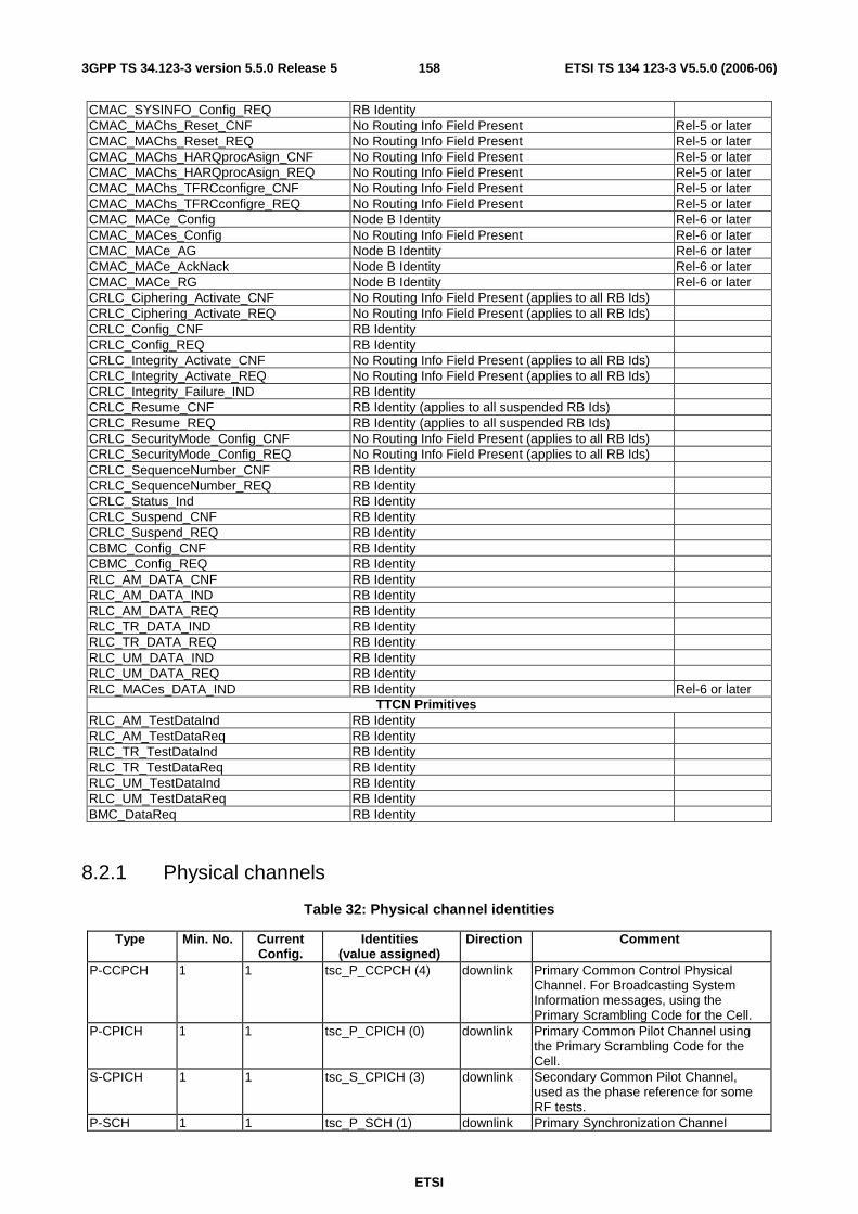
ETSI
ETSI TS 134 123-3 V5.5.0 (2006-06) 1583GPP TS 34.123-3 version 5.5.0 Release 5
CMAC_SYSINFO_Config_REQ RB Identity CMAC_MAChs_Reset_CNF No Routing Info Field Present Rel-5 or later CMAC_MAChs_Reset_REQ No Routing Info Field Present Rel-5 or later CMAC_MAChs_HARQprocAsign_CNF No Routing Info Field Present Rel-5 or later CMAC_MAChs_HARQprocAsign_REQ No Routing Info Field Present Rel-5 or later CMAC_MAChs_TFRCconfigre_CNF No Routing Info Field Present Rel-5 or later CMAC_MAChs_TFRCconfigre_REQ No Routing Info Field Present Rel-5 or later CMAC_MACe_Config Node B Identity Rel-6 or later CMAC_MACes_Config No Routing Info Field Present Rel-6 or later CMAC_MACe_AG Node B Identity Rel-6 or later CMAC_MACe_AckNack Node B Identity Rel-6 or later CMAC_MACe_RG Node B Identity Rel-6 or later CRLC_Ciphering_Activate_CNF No Routing Info Field Present (applies to all RB Ids) CRLC_Ciphering_Activate_REQ No Routing Info Field Present (applies to all RB Ids) CRLC_Config_CNF RB Identity CRLC_Config_REQ RB Identity CRLC_Integrity_Activate_CNF No Routing Info Field Present (applies to all RB Ids) CRLC_Integrity_Activate_REQ No Routing Info Field Present (applies to all RB Ids) CRLC_Integrity_Failure_IND RB Identity CRLC_Resume_CNF RB Identity (applies to all suspended RB Ids) CRLC_Resume_REQ RB Identity (applies to all suspended RB Ids) CRLC_SecurityMode_Config_CNF No Routing Info Field Present (applies to all RB Ids) CRLC_SecurityMode_Config_REQ No Routing Info Field Present (applies to all RB Ids) CRLC_SequenceNumber_CNF RB Identity CRLC_SequenceNumber_REQ RB Identity CRLC_Status_Ind RB Identity CRLC_Suspend_CNF RB Identity CRLC_Suspend_REQ RB Identity CBMC_Config_CNF RB Identity CBMC_Config_REQ RB Identity RLC_AM_DATA_CNF RB Identity RLC_AM_DATA_IND RB Identity RLC_AM_DATA_REQ RB Identity RLC_TR_DATA_IND RB Identity RLC_TR_DATA_REQ RB Identity RLC_UM_DATA_IND RB Identity RLC_UM_DATA_REQ RB Identity RLC_MACes_DATA_IND RB Identity Rel-6 or later
TTCN Primitives RLC_AM_TestDataInd RB Identity RLC_AM_TestDataReq RB Identity RLC_TR_TestDataInd RB Identity RLC_TR_TestDataReq RB Identity RLC_UM_TestDataInd RB Identity RLC_UM_TestDataReq RB Identity BMC_DataReq RB Identity
8.2.1 Physical channels
Table 32: Physical channel identities
Type Min. No. Current Config.
Identities (value assigned)
Direction Comment
P-CCPCH 1 1 tsc_P_CCPCH (4) downlink Primary Common Control Physical Channel. For Broadcasting System Information messages, using the Primary Scrambling Code for the Cell.
P-CPICH 1 1 tsc_P_CPICH (0) downlink Primary Common Pilot Channel using the Primary Scrambling Code for the Cell.
S-CPICH 1 1 tsc_S_CPICH (3) downlink Secondary Common Pilot Channel, used as the phase reference for some RF tests.
P-SCH 1 1 tsc_P_SCH (1) downlink Primary Synchronization Channel

ETSI
ETSI TS 134 123-3 V5.5.0 (2006-06) 1593GPP TS 34.123-3 version 5.5.0 Release 5
Type Min. No. Current Config.
Identities (value assigned)
Direction Comment
S-SCH 1 1 tsc_S_SCH (2) downlink Secondary Synchronization Channel S-CCPCH 3 1 tsc_S_CCPCH1 (5)
tsc_S_CCPCH2 (10) tsc_S_CCPCH3 (13)
downlink Secondary Common Control Physical Channel.
PICH 1 1 tsc_PICH1 (6) tsc_PICH2 (11)
downlink To identify whether the UE should access the PCCH for Paging Messages.
AICH 1 1 tsc_AICH1 (7) tsc_AICH2 (12)
downlink General Acquisition Indicator Channel, can be used for: - Acquisition Indicator Channel, for PRACH - Access Preamble Acquisition Indicator Channel (AP-ICH), for PCPCH - Collision-Detection/Channel- Assignment Indicator Channel (CD/CA-ICH), for PCPCH
DPCH 3 1 tsc_DL_DPCH1 (26) tsc_DL_DPCH2 (27)
downlink Downlink Physical Data Channel. Layer 1 signalling is transmitted only on the first DPCH. This number is for the First Cell. Additional Cells may define a lower number which should be at least 1.
DPDCH 1 1 tsc_UL_DPCH1 (20) tsc_UL_DPCH2 (21)
uplink Uplink Dedicated Physical Channel. A single DPCCH associated with all the DPDCHs used for Layer 1 signalling.
PRACH 2 1 tsc_PRACH1 (8) tsc_PRACH2 (9)
uplink Physical Random Access Channel.
PCPCH 1 FFS uplink Physical Common Packet Channel. CSICH 1 FFS downlink CPCH Status Indicator Channel HS-PDSCH 1 tsc_HSPDSCH(18) downlink Rel-5 or later
High speed physical downlink shared channel
E-AGCH 1 tsc_E_AGCH (14) downlink Rel-6 or later E-DCH Absolute Grant Channel
E-HICH 1 tsc_E_HICH (15) downlink Rel-6 or later E-DCH HARQ Acknowledgement Indicator Channel
E-RGCH 1 tsc_E_RGCH (16) downlink Rel-6 or later E-DCH Relative Grant Channel
E-DPDCH 1 tsc_E_DPCH (22) uplink Rel-6 or later Enhanced Dedicated Physical Channel
F-DPCH 1 tsc_F_DPCH (28) downlink Rel-6 or later Fractional Dedicated Physical Channel
The Physical Channel values 20 to 25 are assigned to uplink DPCHs and the values 26 to 31 are assigned to downlink DPCHs/ FDPCHs.
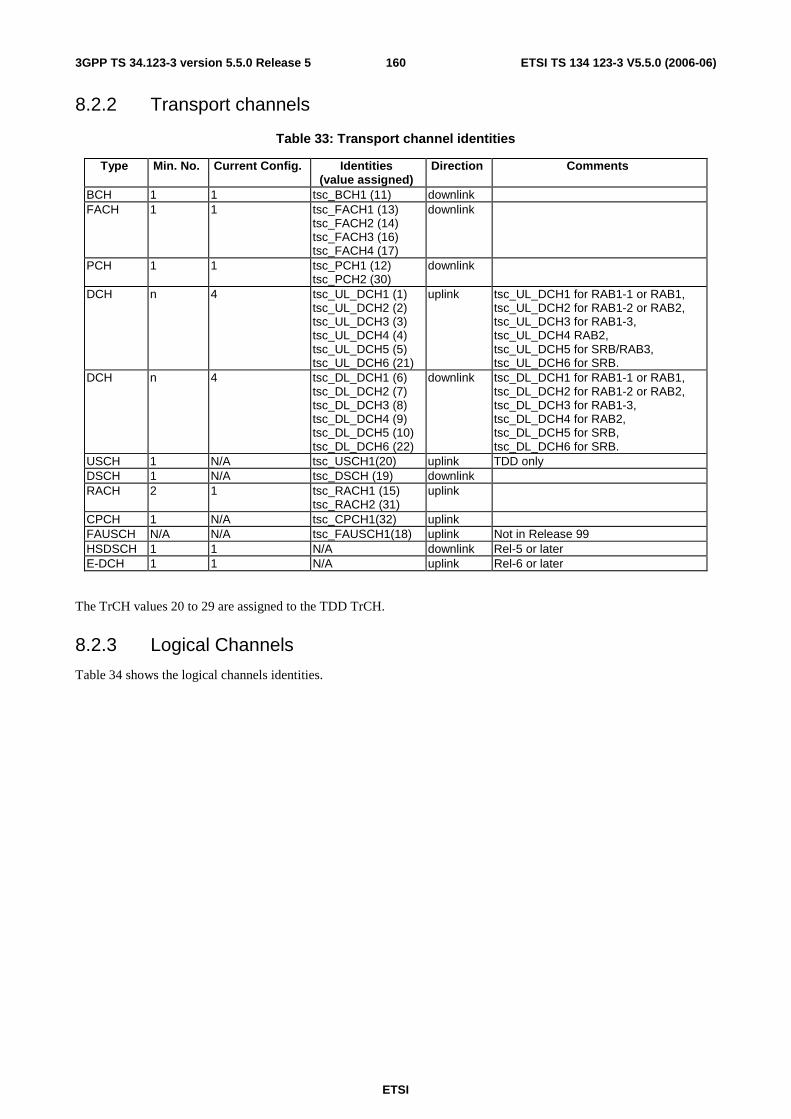
ETSI
ETSI TS 134 123-3 V5.5.0 (2006-06) 1603GPP TS 34.123-3 version 5.5.0 Release 5
8.2.2 Transport channels
Table 33: Transport channel identities
Type Min. No. Current Config. Identities (value assigned)
Direction Comments
BCH 1 1 tsc_BCH1 (11) downlink FACH 1 1 tsc_FACH1 (13)
tsc_FACH2 (14) tsc_FACH3 (16) tsc_FACH4 (17)
downlink
PCH 1 1 tsc_PCH1 (12) tsc_PCH2 (30)
downlink
DCH n 4 tsc_UL_DCH1 (1) tsc_UL_DCH2 (2) tsc_UL_DCH3 (3) tsc_UL_DCH4 (4) tsc_UL_DCH5 (5) tsc_UL_DCH6 (21)
uplink tsc_UL_DCH1 for RAB1-1 or RAB1, tsc_UL_DCH2 for RAB1-2 or RAB2, tsc_UL_DCH3 for RAB1-3, tsc_UL_DCH4 RAB2, tsc_UL_DCH5 for SRB/RAB3, tsc_UL_DCH6 for SRB.
DCH n 4 tsc_DL_DCH1 (6) tsc_DL_DCH2 (7) tsc_DL_DCH3 (8) tsc_DL_DCH4 (9) tsc_DL_DCH5 (10) tsc_DL_DCH6 (22)
downlink tsc_DL_DCH1 for RAB1-1 or RAB1, tsc_DL_DCH2 for RAB1-2 or RAB2, tsc_DL_DCH3 for RAB1-3, tsc_DL_DCH4 for RAB2, tsc_DL_DCH5 for SRB, tsc_DL_DCH6 for SRB.
USCH 1 N/A tsc_USCH1(20) uplink TDD only DSCH 1 N/A tsc_DSCH (19) downlink RACH 2 1 tsc_RACH1 (15)
tsc_RACH2 (31) uplink
CPCH 1 N/A tsc_CPCH1(32) uplink FAUSCH N/A N/A tsc_FAUSCH1(18) uplink Not in Release 99 HSDSCH 1 1 N/A downlink Rel-5 or later E-DCH 1 1 N/A uplink Rel-6 or later
The TrCH values 20 to 29 are assigned to the TDD TrCH.
8.2.3 Logical Channels
Table 34 shows the logical channels identities.
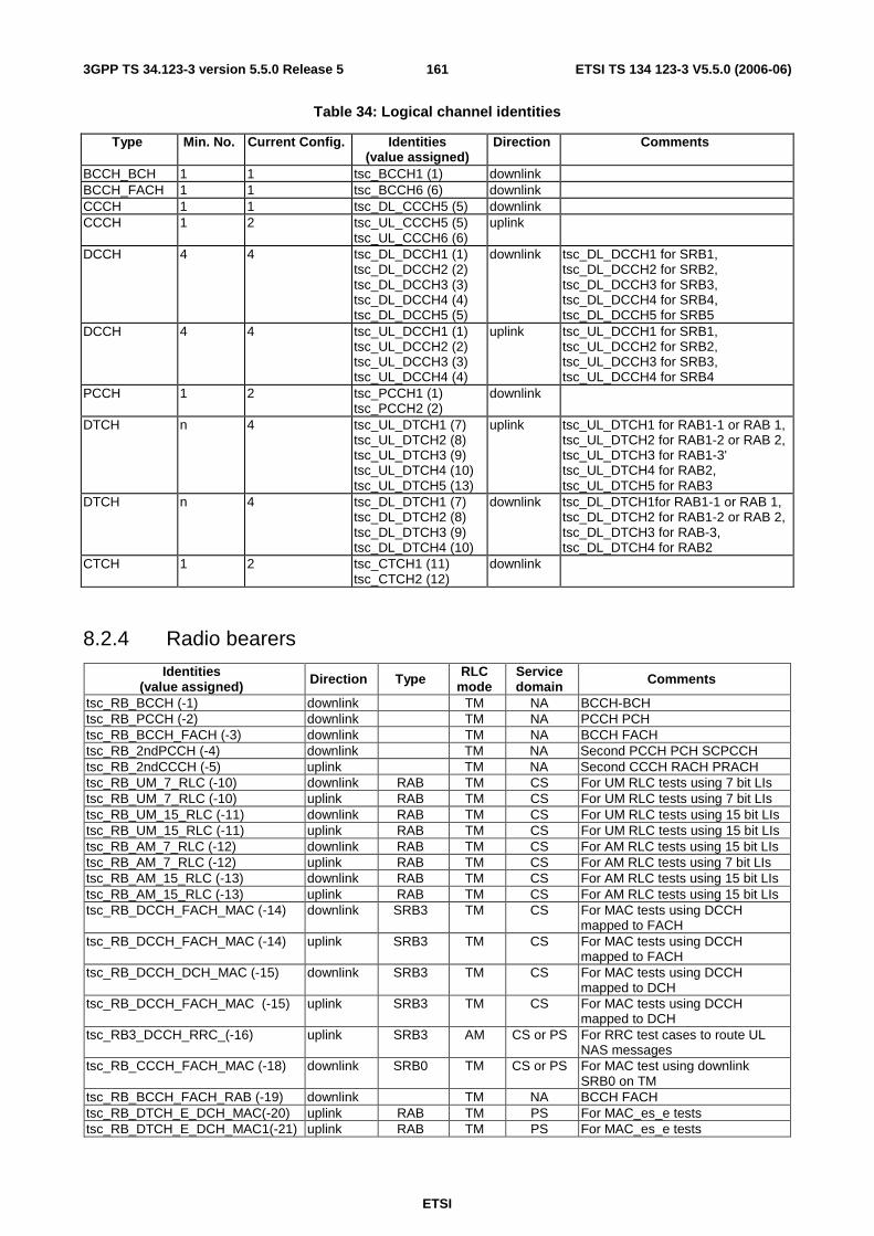
ETSI
ETSI TS 134 123-3 V5.5.0 (2006-06) 1613GPP TS 34.123-3 version 5.5.0 Release 5
Table 34: Logical channel identities
Type Min. No. Current Config. Identities (value assigned)
Direction Comments
BCCH_BCH 1 1 tsc_BCCH1 (1) downlink BCCH_FACH 1 1 tsc_BCCH6 (6) downlink CCCH 1 1 tsc_DL_CCCH5 (5) downlink CCCH 1 2 tsc_UL_CCCH5 (5)
tsc_UL_CCCH6 (6) uplink
DCCH 4 4 tsc_DL_DCCH1 (1) tsc_DL_DCCH2 (2) tsc_DL_DCCH3 (3) tsc_DL_DCCH4 (4) tsc_DL_DCCH5 (5)
downlink tsc_DL_DCCH1 for SRB1, tsc_DL_DCCH2 for SRB2, tsc_DL_DCCH3 for SRB3, tsc_DL_DCCH4 for SRB4, tsc_DL_DCCH5 for SRB5
DCCH 4 4 tsc_UL_DCCH1 (1) tsc_UL_DCCH2 (2) tsc_UL_DCCH3 (3) tsc_UL_DCCH4 (4)
uplink tsc_UL_DCCH1 for SRB1, tsc_UL_DCCH2 for SRB2, tsc_UL_DCCH3 for SRB3, tsc_UL_DCCH4 for SRB4
PCCH 1 2 tsc_PCCH1 (1) tsc_PCCH2 (2)
downlink
DTCH n 4 tsc_UL_DTCH1 (7) tsc_UL_DTCH2 (8) tsc_UL_DTCH3 (9) tsc_UL_DTCH4 (10) tsc_UL_DTCH5 (13)
uplink tsc_UL_DTCH1 for RAB1-1 or RAB 1, tsc_UL_DTCH2 for RAB1-2 or RAB 2, tsc_UL_DTCH3 for RAB1-3' tsc_UL_DTCH4 for RAB2, tsc_UL_DTCH5 for RAB3
DTCH n 4 tsc_DL_DTCH1 (7) tsc_DL_DTCH2 (8) tsc_DL_DTCH3 (9) tsc_DL_DTCH4 (10)
downlink tsc_DL_DTCH1for RAB1-1 or RAB 1, tsc_DL_DTCH2 for RAB1-2 or RAB 2, tsc_DL_DTCH3 for RAB-3, tsc_DL_DTCH4 for RAB2
CTCH 1 2 tsc_CTCH1 (11) tsc_CTCH2 (12)
downlink
8.2.4 Radio bearers
Identities (value assigned) Direction Type RLC
mode Service domain Comments
tsc_RB_BCCH (-1) downlink TM NA BCCH-BCH tsc_RB_PCCH (-2) downlink TM NA PCCH PCH tsc_RB_BCCH_FACH (-3) downlink TM NA BCCH FACH tsc_RB_2ndPCCH (-4) downlink TM NA Second PCCH PCH SCPCCH tsc_RB_2ndCCCH (-5) uplink TM NA Second CCCH RACH PRACH tsc_RB_UM_7_RLC (-10) downlink RAB TM CS For UM RLC tests using 7 bit LIs tsc_RB_UM_7_RLC (-10) uplink RAB TM CS For UM RLC tests using 7 bit LIs tsc_RB_UM_15_RLC (-11) downlink RAB TM CS For UM RLC tests using 15 bit LIs tsc_RB_UM_15_RLC (-11) uplink RAB TM CS For UM RLC tests using 15 bit LIs tsc_RB_AM_7_RLC (-12) downlink RAB TM CS For AM RLC tests using 15 bit LIs tsc_RB_AM_7_RLC (-12) uplink RAB TM CS For AM RLC tests using 7 bit LIs tsc_RB_AM_15_RLC (-13) downlink RAB TM CS For AM RLC tests using 15 bit LIs tsc_RB_AM_15_RLC (-13) uplink RAB TM CS For AM RLC tests using 15 bit LIs tsc_RB_DCCH_FACH_MAC (-14) downlink SRB3 TM CS For MAC tests using DCCH
mapped to FACH tsc_RB_DCCH_FACH_MAC (-14) uplink SRB3 TM CS For MAC tests using DCCH
mapped to FACH tsc_RB_DCCH_DCH_MAC (-15) downlink SRB3 TM CS For MAC tests using DCCH
mapped to DCH tsc_RB_DCCH_FACH_MAC (-15) uplink SRB3 TM CS For MAC tests using DCCH
mapped to DCH tsc_RB3_DCCH_RRC_(-16) uplink SRB3 AM CS or PS For RRC test cases to route UL
NAS messages tsc_RB_CCCH_FACH_MAC (-18) downlink SRB0 TM CS or PS For MAC test using downlink
SRB0 on TM tsc_RB_BCCH_FACH_RAB (-19) downlink TM NA BCCH FACH tsc_RB_DTCH_E_DCH_MAC(-20) uplink RAB TM PS For MAC_es_e tests tsc_RB_DTCH_E_DCH_MAC1(-21) uplink RAB TM PS For MAC_es_e tests
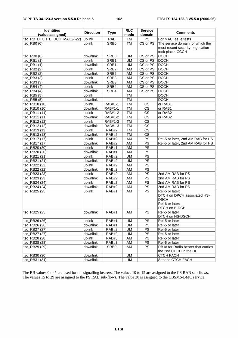
ETSI
ETSI TS 134 123-3 V5.5.0 (2006-06) 1623GPP TS 34.123-3 version 5.5.0 Release 5
Identities (value assigned) Direction Type RLC
mode Service domain Comments
tsc_RB_DTCH_E_DCH_MAC2(-22) uplink RAB TM PS For MAC_es_e tests tsc_RB0 (0) uplink SRB0 TM CS or PS The service domain for which the
most recent security negotiation took place. CCCH
tsc_RB0 (0) downlink SRB0 UM CS or PS CCCH tsc_RB1 (1) uplink SRB1 UM CS or PS DCCH tsc_RB1 (1) downlink SRB1 UM CS or PS DCCH tsc_RB2 (2) uplink SRB2 AM CS or PS DCCH tsc_RB2 (2) downlink SRB2 AM CS or PS DCCH tsc_RB3 (3) uplink SRB3 AM CS or PS DCCH tsc_RB3 (3) downlink SRB3 AM CS or PS DCCH tsc_RB4 (4) uplink SRB4 AM CS or PS DCCH tsc_RB4 (4) downlink SRB4 AM CS or PS DCCH tsc_RB5 (5) uplink TM DCCH tsc_RB5 (5) downlink TM DCCH tsc_RB10 (10) uplink RAB#1-1 TM CS or RAB1 tsc_RB10 (10) downlink RAB#1-1 TM CS or RAB1 tsc_RB11 (11) uplink RAB#1-2 TM CS or RAB2 tsc_RB11 (11) downlink RAB#1-2 TM CS or RAB2 tsc_RB12 (12) uplink RAB#1-3 TM CS tsc_RB12 (12) downlink RAB#1-3 TM CS tsc_RB13 (13) uplink RAB#2 TM CS tsc_RB13 (13) downlink RAB#2 TM CS tsc_RB17 (17) uplink RAB#2 AM PS Rel-5 or later, 2nd AM RAB for HS tsc_RB17 (17) downlink RAB#2 AM PS Rel-5 or later, 2nd AM RAB for HS tsc_RB20 (20) uplink RAB#1 AM PS tsc_RB20 (20) downlink RAB#1 AM PS tsc_RB21 (21) uplink RAB#2 UM PS tsc_RB21 (21) downlink RAB#2 UM PS tsc_RB22 (22) uplink RAB#2 AM PS tsc_RB22 (22) downlink RAB#2 AM PS tsc_RB23 (23) uplink RAB#2 AM PS 2nd AM RAB for PS tsc_RB23 (23) downlink RAB#2 AM PS 2nd AM RAB for PS tsc_RB24 (24) uplink RAB#2 AM PS 2nd AM RAB for PS tsc_RB24 (24) downlink RAB#2 AM PS 2nd AM RAB for PS tsc_RB25 (25) uplink RAB#1 AM PS Rel-5 or later:
DTCH on DPCH associated HS-DSCH Rel-6 or later: DTCH on E-DCH
tsc_RB25 (25) downlink RAB#1 AM PS Rel-5 or later DTCH on HS-DSCH
tsc_RB26 (26) uplink RAB#1 UM PS Rel-5 or later tsc_RB26 (26) downlink RAB#1 UM PS Rel-5 or later tsc_RB27 (27) uplink RAB#2 UM PS Rel-5 or later tsc_RB27 (27) downlink RAB#2 UM PS Rel-5 or later tsc_RB28 (28) uplink RAB#3 AM PS Rel-5 or later tsc_RB28 (28) downlink RAB#3 AM PS Rel-5 or later tsc_RB29 (29) downlink SRB0 AM PS RB Id for Radio bearer that carries
the 2nd CCCH in the DL tsc_RB30 (30) downlink UM CTCH FACH tsc_RB31 (31) downlink UM Second CTCH FACH
The RB values 0 to 5 are used for the signalling bearers. The values 10 to 15 are assigned to the CS RAB sub-flows. The values 15 to 29 are assigned to the PS RAB sub-flows. The value 30 is assigned to the CBSMS/BMC service.
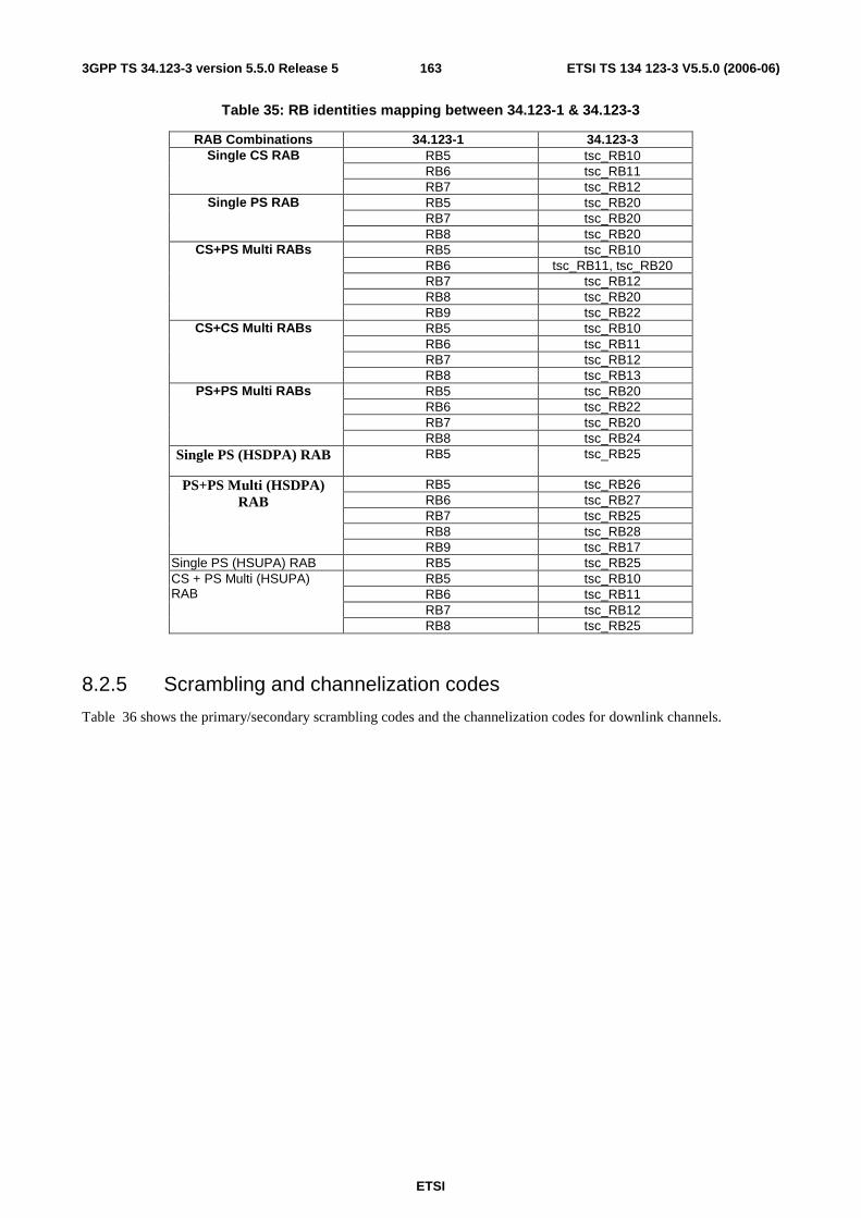
ETSI
ETSI TS 134 123-3 V5.5.0 (2006-06) 1633GPP TS 34.123-3 version 5.5.0 Release 5
Table 35: RB identities mapping between 34.123-1 & 34.123-3
RAB Combinations 34.123-1 34.123-3 RB5 tsc_RB10 RB6 tsc_RB11
Single CS RAB
RB7 tsc_RB12 RB5 tsc_RB20 RB7 tsc_RB20
Single PS RAB
RB8 tsc_RB20 RB5 tsc_RB10 RB6 tsc_RB11, tsc_RB20 RB7 tsc_RB12 RB8 tsc_RB20
CS+PS Multi RABs
RB9 tsc_RB22 RB5 tsc_RB10 RB6 tsc_RB11 RB7 tsc_RB12
CS+CS Multi RABs
RB8 tsc_RB13 RB5 tsc_RB20 RB6 tsc_RB22 RB7 tsc_RB20
PS+PS Multi RABs
RB8 tsc_RB24 Single PS (HSDPA) RAB RB5 tsc_RB25
RB5 tsc_RB26 RB6 tsc_RB27 RB7 tsc_RB25 RB8 tsc_RB28
PS+PS Multi (HSDPA) RAB
RB9 tsc_RB17 Single PS (HSUPA) RAB RB5 tsc_RB25
RB5 tsc_RB10 RB6 tsc_RB11 RB7 tsc_RB12
CS + PS Multi (HSUPA) RAB
RB8 tsc_RB25
8.2.5 Scrambling and channelization codes
Table 36 shows the primary/secondary scrambling codes and the channelization codes for downlink channels.
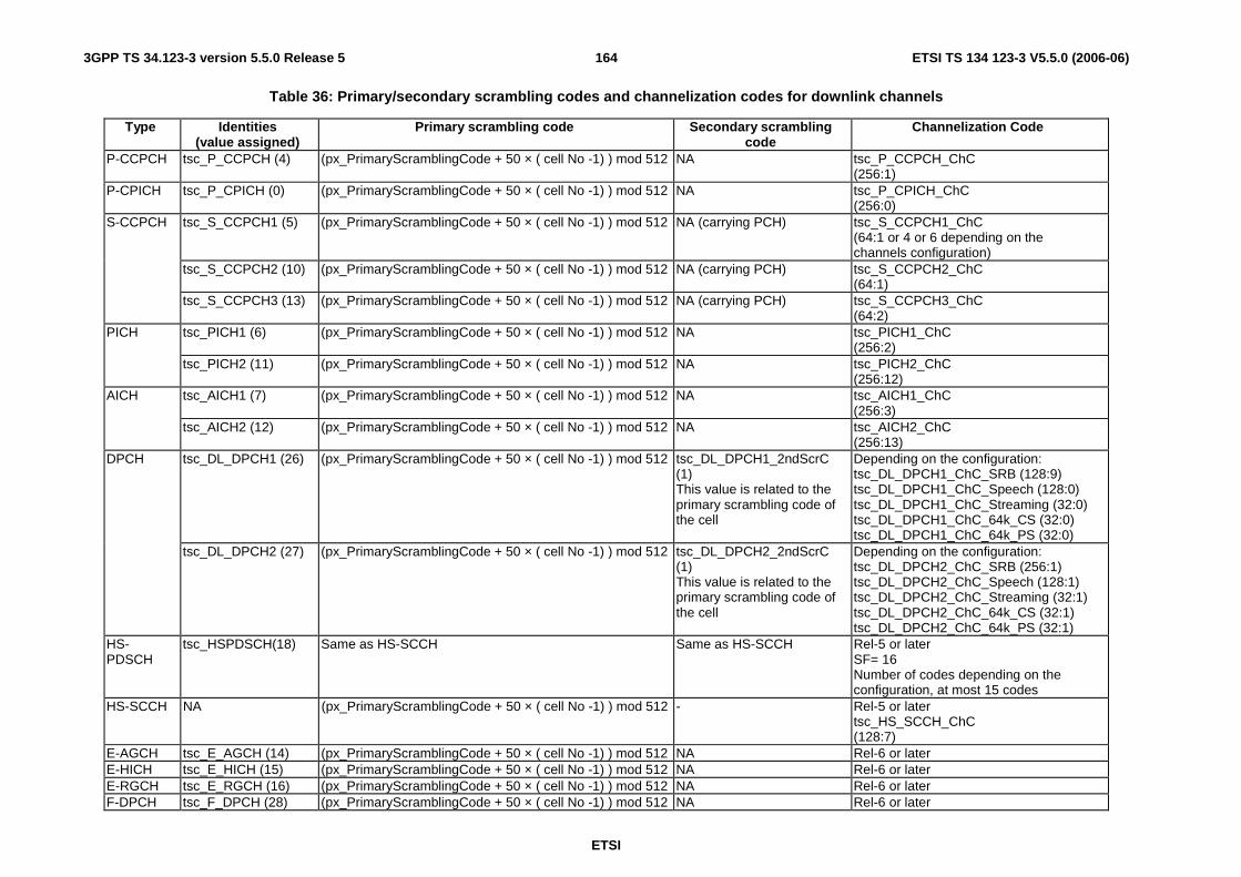
ETSI
ETSI TS 134 123-3 V5.5.0 (2006-06) 1643GPP TS 34.123-3 version 5.5.0 Release 5
Table 36: Primary/secondary scrambling codes and channelization codes for downlink channels
Type Identities (value assigned)
Primary scrambling code Secondary scrambling code
Channelization Code
P-CCPCH tsc_P_CCPCH (4) (px_PrimaryScramblingCode + 50 × ( cell No -1) ) mod 512 NA tsc_P_CCPCH_ChC (256:1)
P-CPICH tsc_P_CPICH (0) (px_PrimaryScramblingCode + 50 × ( cell No -1) ) mod 512 NA tsc_P_CPICH_ChC (256:0)
tsc_S_CCPCH1 (5) (px_PrimaryScramblingCode + 50 × ( cell No -1) ) mod 512 NA (carrying PCH) tsc_S_CCPCH1_ChC (64:1 or 4 or 6 depending on the channels configuration)
tsc_S_CCPCH2 (10) (px_PrimaryScramblingCode + 50 × ( cell No -1) ) mod 512 NA (carrying PCH) tsc_S_CCPCH2_ChC (64:1)
S-CCPCH
tsc_S_CCPCH3 (13) (px_PrimaryScramblingCode + 50 × ( cell No -1) ) mod 512 NA (carrying PCH) tsc_S_CCPCH3_ChC (64:2)
tsc_PICH1 (6) (px_PrimaryScramblingCode + 50 × ( cell No -1) ) mod 512 NA tsc_PICH1_ChC (256:2)
PICH
tsc_PICH2 (11) (px_PrimaryScramblingCode + 50 × ( cell No -1) ) mod 512 NA tsc_PICH2_ChC (256:12)
tsc_AICH1 (7) (px_PrimaryScramblingCode + 50 × ( cell No -1) ) mod 512 NA tsc_AICH1_ChC (256:3)
AICH
tsc_AICH2 (12) (px_PrimaryScramblingCode + 50 × ( cell No -1) ) mod 512 NA tsc_AICH2_ChC (256:13)
tsc_DL_DPCH1 (26) (px_PrimaryScramblingCode + 50 × ( cell No -1) ) mod 512 tsc_DL_DPCH1_2ndScrC (1) This value is related to the primary scrambling code of the cell
Depending on the configuration: tsc_DL_DPCH1_ChC_SRB (128:9) tsc_DL_DPCH1_ChC_Speech (128:0) tsc_DL_DPCH1_ChC_Streaming (32:0) tsc_DL_DPCH1_ChC_64k_CS (32:0) tsc_DL_DPCH1_ChC_64k_PS (32:0)
DPCH
tsc_DL_DPCH2 (27) (px_PrimaryScramblingCode + 50 × ( cell No -1) ) mod 512 tsc_DL_DPCH2_2ndScrC (1) This value is related to the primary scrambling code of the cell
Depending on the configuration: tsc_DL_DPCH2_ChC_SRB (256:1) tsc_DL_DPCH2_ChC_Speech (128:1) tsc_DL_DPCH2_ChC_Streaming (32:1) tsc_DL_DPCH2_ChC_64k_CS (32:1) tsc_DL_DPCH2_ChC_64k_PS (32:1)
HS-PDSCH
tsc_HSPDSCH(18) Same as HS-SCCH Same as HS-SCCH Rel-5 or later SF= 16 Number of codes depending on the configuration, at most 15 codes
HS-SCCH NA (px_PrimaryScramblingCode + 50 × ( cell No -1) ) mod 512 - Rel-5 or later tsc_HS_SCCH_ChC (128:7)
E-AGCH tsc_E_AGCH (14) (px_PrimaryScramblingCode + 50 × ( cell No -1) ) mod 512 NA Rel-6 or later E-HICH tsc_E_HICH (15) (px_PrimaryScramblingCode + 50 × ( cell No -1) ) mod 512 NA Rel-6 or later E-RGCH tsc_E_RGCH (16) (px_PrimaryScramblingCode + 50 × ( cell No -1) ) mod 512 NA Rel-6 or later F-DPCH tsc_F_DPCH (28) (px_PrimaryScramblingCode + 50 × ( cell No -1) ) mod 512 NA Rel-6 or later

ETSI
ETSI TS 134 123-3 V5.5.0 (2006-06) 1653GPP TS 34.123-3 version 5.5.0 Release 5
Table 37 shows the scrambling codes, the signatures and the spreading factors for uplink channels.
Table 37: Scrambling codes, signatures and spreading factor for uplink channels
Type Identities (value assigned)
Scrambling code Signature Spreading factor
tsc_UL_DPCH1 (20)
(px_UL_ScramblingCode + 1000*( cell No -1)) MOD
16777216
NA If only one DPDCH and depending on the configuration tsc_UL_DPDCH_SF_SRB (64) tsc_UL_DPDCH_SF_Speech (64) tsc_UL_DPDCH_SF_Streaming (16) tsc_UL_DPDCH_SF_64k_CS (16) tsc_UL_DPDCH_SF_64k_PS (16) If more than one DPDCH tsc_UL_DPDCH_SF_4 (4:1)
DPDCH
tsc_UL_DPCH2 (21)
(px_UL_ScramblingCode + 1 000 × ( cell No -1)) MOD
16 777 216
NA If only one DPDCH and depending on the configuration tsc_UL_DPDCH_SF_SRB (64) tsc_UL_DPDCH_SF_Speech (64) tsc_UL_DPDCH_SF_Streaming (16) tsc_UL_DPDCH_SF_64k_CS (16) tsc_UL_DPDCH_SF_64k_PS (16) If more than one DPDCH tsc_UL_DPDCH_SF_4 (4:1)
tsc_PRACH1 (8)
tsc_PRACH1_ScrC (0)
tsc_PRACH1_Signatures ('0000000011111111'B)
tsc_PRACH1_SF (64)
PRACH
tsc_PRACH2 (9)
tsc_PRACH2_ScrC (1)
tsc_PRACH2_Signatures ('0000000011111111'B)
tsc_PRACH2_SF (64)
HS-DPCCH
NA Same as DPDCH NA Rel-5 or later Depending on the number of DPDCHs: If only one DPDCH: C256,64; If 2 or 4 or 6 DPDCHs: C256,1; If 3 or 5 DPDCHs: C256,32.
E-DPCH tsc_E_DPCH (22) Same as DPDCH NA Rel-6 or later

ETSI
ETSI TS 134 123-3 V5.5.0 (2006-06) 1663GPP TS 34.123-3 version 5.5.0 Release 5
8.2.6 MAC-d
MAC-d and the served RLC are cell-independent and are configured by using the cell-id = -1. During reconfigurations, cell changes and state transitions, the relevant counters in the RLC and MAC-d are maintained.
For the active set updating, the DL DCH with the same channel Id in the different cells are implicitly connected to form the DL multiple paths.
8.2.6.1 MAC-d configuration examples
The following example shows how the MAC and RLC ASP are used to configure different configurations.
The 1st parameter in ASP represents the cell identity: p_CellId corresponds to the current cell identity, tsc_CellDedicated corresponds to the cell independent (-1). The 2nd parameter represents the channel Id, this parameter is not needed in the CRLC ASP).
1. Cell_DCH_StandAloneSRB: configuration of DL/UL-DPCH1
CPHY!CPHY_RL_Setup_REQ ( p_CellId, tsc_DL_DPCH1) -- Cell concerned CPHY?CPHY_RL_Setup_CNF ( p_CellId, tsc_DL_DPCH1) -- Cell concerned CPHY!CPHY_TrCH_Config_REQ ( p_CellId, tsc_DL_DPCH1) -- Cell concerned CPHY?CPHY_TrCH_Config_CNF ( p_CellId, tsc_DL_DPCH1 ) -- Cell concerned CMAC ! CMAC_Config_REQ ( tsc_CellDedicated, tsc_DL_DPCH1) -- Cell independent (-1) CMAC ? CMAC_Config_CNF ( tsc_CellDedicated, tsc_DL_DPCH1) -- Cell independent (-1) CPHY!CPHY_RL_Setup_REQ ( p_CellId, tsc_UL_DPCH1) -- Cell concerned CPHY?CPHY_RL_Setup_CNF ( p_CellId, tsc_UL_DPCH1) -- Cell concerned CPHY!CPHY_TrCH_Config_REQ ( p_CellId, tsc_UL_DPCH1 ) -- Cell concerned CPHY?CPHY_TrCH_Config_CNF ( p_CellId, tsc_UL_DPCH1 ) -- Cell concerned CMAC ! CMAC_Config_REQ ( tsc_CellDedicated, tsc_UL_DPCH1) -- Cell independent (-1) CMAC ? CMAC_Config_CNF ( tsc_CellDedicated, tsc_UL_DPCH1 ) -- Cell independent (-1) CRLC ! CRLC_Config_REQ ( tsc_CellDedicated ) -- Cell independent (-1) CRLC ? CRLC_Config_CNF ( tsc_CellDedicated ) -- Cell independent (-1)
2. Cell_FACH: configuration of S-CCPCH1
CPHY!CPHY_RL_Setup_REQ ( p_CellId, tsc_S_CCPCH1) -- Cell concerned CPHY?CPHY_RL_Setup_CNF ( p_CellId, tsc_S_CCPCH1) -- Cell concerned t CPHY!CPHY_TrCH_Config_REQ ( p_CellId, tsc_S_CCPCH1) -- Cell concerned CPHY ? CPHY_TrCH_Config_CNF ( p_CellId, tsc_S_CCPCH1) -- Cell concerned CMAC ! CMAC_Config_REQ ( p_CellId, tsc_S_CCPCH1) -- Cell concerned CMAC ? CMAC_Config_CNF ( p_CellId, tsc_S_CCPCH1 ) -- Cell concerned CPHY!CPHY_RL_Setup_REQ ( p_CellId, tsc_PICH1 -- Cell concerned CPHY?CPHY_RL_Setup_CNF ( p_CellId, tsc_PICH1) -- Cell concerned CRLC ! CRLC_Config_REQ ( tsc_CellDedicated ) -- Cell independent (-1) CRLC ? CRLC_Config_CNF ( tsc_CellDedicated ) -- Cell independent (-1)
3. Cell_FACH: configuration of P-CCPCH
CPHY!CPHY_RL_Setup_REQ ( p_CellId, tsc_P_CPICH ) -- Cell concerned CPHY?CPHY_RL_Setup_CNF ( p_CellId, tsc_P_CPICH ) -- Cell concerned CPHY!CPHY_RL_Setup_REQ ( p_CellId, tsc_P_SCH) -- Cell concerned CPHY?CPHY_RL_Setup_CNF ( p_CellId, tsc_P_SCH ) -- Cell concerned CPHY!CPHY_RL_Setup_REQ ( p_CellId, tsc_P_SCH) -- Cell concerned CPHY?CPHY_RL_Setup_CNF ( p_CellId, tsc_S_SCH ) -- Cell concerned CPHY!CPHY_RL_Setup_REQ ( p_CellId, tsc_P_CCPCH) -- Cell concerned CPHY?CPHY_RL_Setup_CNF ( p_CellId, tsc_P_CCPCH ) -- Cell concerned CPHY!CPHY_TrCH_Config_REQ ( p_CellId, tsc_P_CCPCH ) -- Cell concerned CPHY?CPHY_TrCH_Config_CNF ( p_CellId, tsc_P_CCPCH ) -- Cell concerned CMAC!CMAC_Config_REQ ( p_CellId, tsc_P_CCPCH) -- Cell concerned CMAC?CMAC_Config_CNF ( p_CellId, tsc_P_CCPCH ) -- Cell concerned CRLC! CRLC_Config_REQ ( p_CellId) -- Cell concerned CRLC? CRLC_Config_CNF ( p_CellId) -- Cell concerned

ETSI
ETSI TS 134 123-3 V5.5.0 (2006-06) 1673GPP TS 34.123-3 version 5.5.0 Release 5
8.2.7 Configuration of compressed mode
8.2.7.1 UE Side
Two IE are available for the configuration of the compressed mode for the UE.
a) DPCH_CompressedModeInfo.
b) DPCH_CompressedModeStatusInfo.
Compressed mode initiation at UE side can be divided into 2 steps:
a) Downloading compressed mode parameters.
b) Activating the compressed mode.
Both of them can be done in one shot.
8.2.7.2 SS Side
Compressed mode configuration at SS side shall be maintained the same status as that on the UE side. So there are 3 different types of compressed mode configuration states both on UE and SS side.
- Configuration of compressed mode parameters (Use of DPCH_CompressedModeInfo) without the activation.
- Configuration of compressed mode parameters and simultaneous activation (use of DPCH_CompressedModeInfo).
- Only activation (use of DPCH_CompressedModeStatusInfo).
If compressed mode parameters are to be downloaded to the UE without actually activation, it shall be configured on the SS side by any one of the following two procedures.
- If DPCH channel on which compressed mode is to be downloaded is not already configured, primitive "CPHY_RL_Setup_REQ", with "CphyRlSetupReq. PhysicalChannelInfo" which is of choice, chosen to dPCHInfo shall be called. The procedure is used to pre-configure all compressed patterns necessary for test, but deactivate the all patterns configured at the beginning of the test. This procedure has not been implemented in the TTCN.
- If DPCH channel on which compressed mode is to be downloaded is already configured, the primitive "CPHY_RL_Modify_REQ" with "CphyRlModifyReq. PhysicalChannelInfo" which is of choice, chosen to dPCHInfo shall be called. This procedure in generally used in the TTCN.
If compressed mode parameters are to be configured and simultaneously activated, the same procedure as for the configuration of compressed mode without activation shall be used.
Activation of the compressed mode, whose parameters are already configured shall be achieved by the primitive "CPHY_RL_Modify_REQ" with "CphyRlModifyReq. PhysicalChannelInfo" which is of choice, chosen to dpch_CompressedModeStatusInfo.
8.2.8 Use of U-RNTI and C-RNTI
The uRNTI and cRNTI are optional when configuring the MAC (CMAC_Config_REQ). Table 38 gives indication on when uRNTI and cRNTI are needed.

ETSI
ETSI TS 134 123-3 V5.5.0 (2006-06) 1683GPP TS 34.123-3 version 5.5.0 Release 5
Table 38: cRNTI and uRNTI in CMAC-Config_REQ
P-CCPCH S-CCPCH with mapped DL-DCCH/DTCH
(UE in cell_FACH)
S-CCPCH without mapped DL-DCCH/DTCH
(UE in cell_DCH)
PRACH with mapped DL-DCCH/DTCH
(UE in cell_FACH)
PRACH without
mapped DL-DCCH/DTCH
(UE in cell_DCH)
DPCH
uRNTI - Included - Omit - - cRNTI - Included - Included - -
CMAC-Config_REQ OMIT both Download cRNTI and uRNTI
OMIT both Download cRNTI
OMIT both OMIT both
In the case of DL-DCCH/DTCH mapped on S-CCPCH, cRNTI and uRNTI are downloaded to the MAC layer. As default, SS MAC shall use cRNTI as UE id. At the CMAC configuration of the beginning of test cases, the RLC payload size is configured, as default on cRNTI for the MAC header calculation. If uRNTI is to be used the SS RLC payload size shall be reconfigured as cRNTI and uRNTI do not have the same length (16 bits and 32 bits respectively).
CELL UPDATE CONFIRM or URA UPDATE CONFIRM shall be sent on DCCH at the test for the ciphering reason except the periodic update without carrying the UE identity information. In this case the CELL UPDATE CONFIRM or URA UPDATE CONFIRM is sent on CCCH at the test.
Table 39: Relationship between cell update cause, UE state and RLC size reconfiguration
Cell update cause UE State (before cell update) CELL UPDATE CONFIRM
CRLC_Reconf RLC_Size Needed
Valid UE ID
Cell reselection CELL_PCH / CELL_FACH DCCH Y U_RNTI Periodical cell update CELL_PCH DCCH or CCCH Y (for DCCH) U_RNTI Periodical cell update CELL_FACH DCCH or CCCH N C_RNTI
Uplink data transmission CELL_PCH / URA _PCH DCCH Y U_RNTI UTRAN paging response CELL_PCH / URA_PCH DCCH Y U_RNTI Re-entered service area CELL_PCH / URA_PCH DCCH Y U_RNTI Re-entered service area CELL_FACH DCCH N C_RNTI
Radio Link failure CELL_DCH DCCH Y U_RNTI RLC_unrecoverable error CELL_DCH / CELL_FACH DCCH Y
N (selected the same cell in
CELL_FACH)
U_RNTI
C_RNTI
8.3 Channels configurations
8.3.1 Configuration of Cell_FACH
The configuration is based on 3GPP TS 34.108 [3], clause 6.10.2.4.3.2.1.2 for downlink and 3GPP TS 34.108 [3], clause 6.10.2.4.4.1.1.1 for uplink. The configuration is applied to the RRC tests related in the states CELL_FACH, CELL_PCH and URA_PCH. They need a minimum radio configuration for testing.
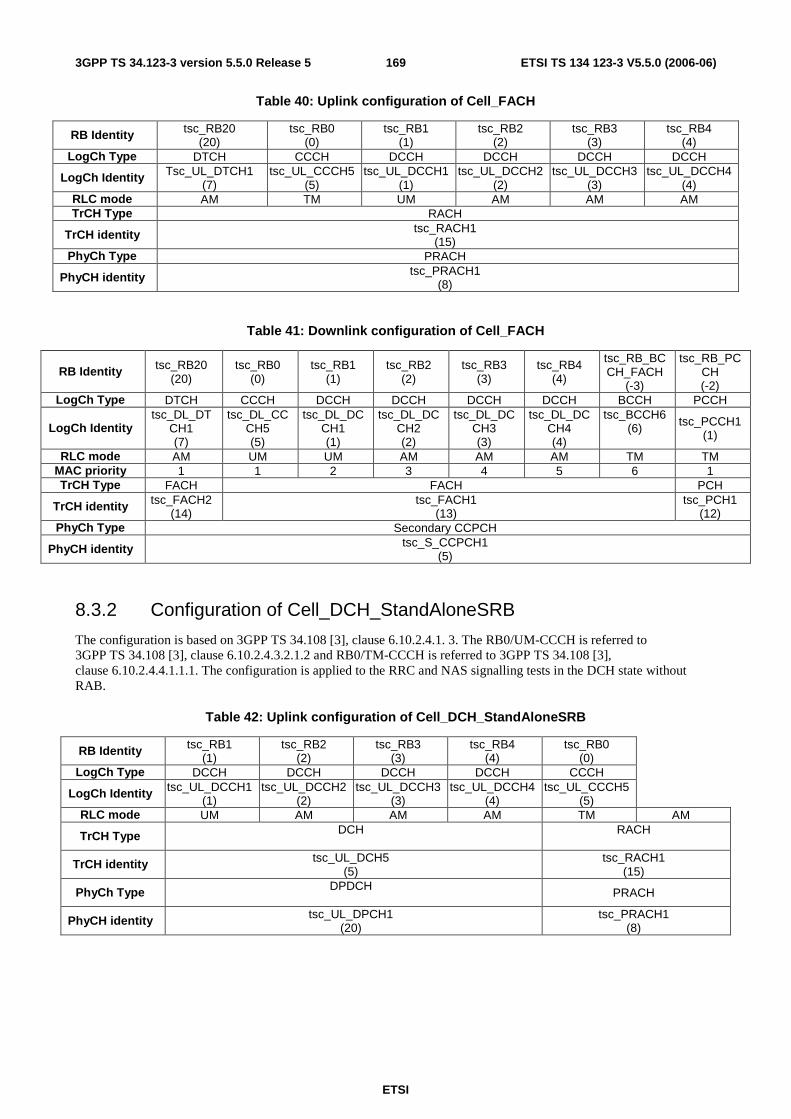
ETSI
ETSI TS 134 123-3 V5.5.0 (2006-06) 1693GPP TS 34.123-3 version 5.5.0 Release 5
Table 40: Uplink configuration of Cell_FACH
RB Identity tsc_RB20 (20)
tsc_RB0 (0)
tsc_RB1 (1)
tsc_RB2 (2)
tsc_RB3 (3)
tsc_RB4 (4)
LogCh Type DTCH CCCH DCCH DCCH DCCH DCCH
LogCh Identity Tsc_UL_DTCH1 (7)
tsc_UL_CCCH5 (5)
tsc_UL_DCCH1 (1)
tsc_UL_DCCH2 (2)
tsc_UL_DCCH3 (3)
tsc_UL_DCCH4 (4)
RLC mode AM TM UM AM AM AM TrCH Type RACH
TrCH identity tsc_RACH1 (15)
PhyCh Type PRACH
PhyCH identity tsc_PRACH1 (8)
Table 41: Downlink configuration of Cell_FACH
RB Identity tsc_RB20 (20)
tsc_RB0 (0)
tsc_RB1 (1)
tsc_RB2 (2)
tsc_RB3 (3)
tsc_RB4 (4)
tsc_RB_BCCH_FACH
(-3)
tsc_RB_PCCH (-2)
LogCh Type DTCH CCCH DCCH DCCH DCCH DCCH BCCH PCCH
LogCh Identity tsc_DL_DT
CH1 (7)
tsc_DL_CCCH5 (5)
tsc_DL_DCCH1 (1)
tsc_DL_DCCH2 (2)
tsc_DL_DCCH3 (3)
tsc_DL_DCCH4 (4)
tsc_BCCH6 (6) tsc_PCCH1
(1)
RLC mode AM UM UM AM AM AM TM TM MAC priority 1 1 2 3 4 5 6 1 TrCH Type FACH FACH PCH
TrCH identity tsc_FACH2 (14)
tsc_FACH1 (13)
tsc_PCH1 (12)
PhyCh Type Secondary CCPCH
PhyCH identity tsc_S_CCPCH1 (5)
8.3.2 Configuration of Cell_DCH_StandAloneSRB
The configuration is based on 3GPP TS 34.108 [3], clause 6.10.2.4.1. 3. The RB0/UM-CCCH is referred to 3GPP TS 34.108 [3], clause 6.10.2.4.3.2.1.2 and RB0/TM-CCCH is referred to 3GPP TS 34.108 [3], clause 6.10.2.4.4.1.1.1. The configuration is applied to the RRC and NAS signalling tests in the DCH state without RAB.
Table 42: Uplink configuration of Cell_DCH_StandAloneSRB
RB Identity tsc_RB1 (1)
tsc_RB2 (2)
tsc_RB3 (3)
tsc_RB4 (4)
tsc_RB0 (0)
LogCh Type DCCH DCCH DCCH DCCH CCCH
LogCh Identity tsc_UL_DCCH1 (1)
tsc_UL_DCCH2 (2)
tsc_UL_DCCH3 (3)
tsc_UL_DCCH4 (4)
tsc_UL_CCCH5 (5)
RLC mode UM AM AM AM TM AM
TrCH Type DCH
RACH
TrCH identity tsc_UL_DCH5 (5)
tsc_RACH1 (15)
PhyCh Type DPDCH PRACH
PhyCH identity tsc_UL_DPCH1 (20)
tsc_PRACH1 (8)
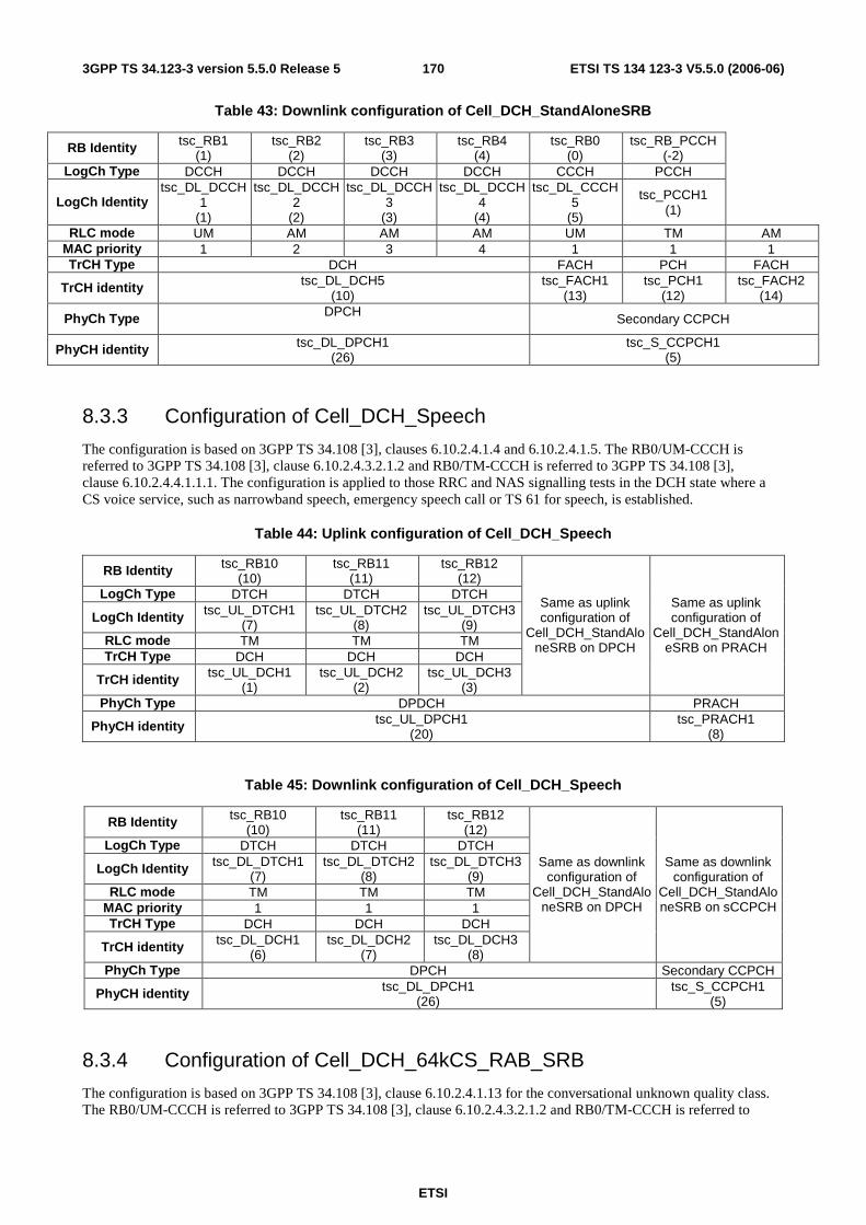
ETSI
ETSI TS 134 123-3 V5.5.0 (2006-06) 1703GPP TS 34.123-3 version 5.5.0 Release 5
Table 43: Downlink configuration of Cell_DCH_StandAloneSRB
RB Identity tsc_RB1 (1)
tsc_RB2 (2)
tsc_RB3 (3)
tsc_RB4 (4)
tsc_RB0 (0)
tsc_RB_PCCH (-2)
LogCh Type DCCH DCCH DCCH DCCH CCCH PCCH
LogCh Identity tsc_DL_DCCH
1 (1)
tsc_DL_DCCH2
(2)
tsc_DL_DCCH3
(3)
tsc_DL_DCCH4
(4)
tsc_DL_CCCH5
(5)
tsc_PCCH1 (1)
RLC mode UM AM AM AM UM TM AM MAC priority 1 2 3 4 1 1 1 TrCH Type DCH FACH PCH FACH
TrCH identity tsc_DL_DCH5 (10)
tsc_FACH1 (13)
tsc_PCH1 (12)
tsc_FACH2 (14)
PhyCh Type DPCH Secondary CCPCH
PhyCH identity tsc_DL_DPCH1 (26)
tsc_S_CCPCH1 (5)
8.3.3 Configuration of Cell_DCH_Speech
The configuration is based on 3GPP TS 34.108 [3], clauses 6.10.2.4.1.4 and 6.10.2.4.1.5. The RB0/UM-CCCH is referred to 3GPP TS 34.108 [3], clause 6.10.2.4.3.2.1.2 and RB0/TM-CCCH is referred to 3GPP TS 34.108 [3], clause 6.10.2.4.4.1.1.1. The configuration is applied to those RRC and NAS signalling tests in the DCH state where a CS voice service, such as narrowband speech, emergency speech call or TS 61 for speech, is established.
Table 44: Uplink configuration of Cell_DCH_Speech
RB Identity tsc_RB10 (10)
tsc_RB11 (11)
tsc_RB12 (12)
LogCh Type DTCH DTCH DTCH
LogCh Identity tsc_UL_DTCH1 (7)
tsc_UL_DTCH2 (8)
tsc_UL_DTCH3 (9)
RLC mode TM TM TM TrCH Type DCH DCH DCH
TrCH identity tsc_UL_DCH1 (1)
tsc_UL_DCH2 (2)
tsc_UL_DCH3 (3)
Same as uplink configuration of
Cell_DCH_StandAloneSRB on DPCH
Same as uplink configuration of
Cell_DCH_StandAloneSRB on PRACH
PhyCh Type DPDCH PRACH
PhyCH identity tsc_UL_DPCH1 (20)
tsc_PRACH1 (8)
Table 45: Downlink configuration of Cell_DCH_Speech
RB Identity tsc_RB10 (10)
tsc_RB11 (11)
tsc_RB12 (12)
LogCh Type DTCH DTCH DTCH
LogCh Identity tsc_DL_DTCH1 (7)
tsc_DL_DTCH2 (8)
tsc_DL_DTCH3 (9)
RLC mode TM TM TM MAC priority 1 1 1 TrCH Type DCH DCH DCH
TrCH identity tsc_DL_DCH1 (6)
tsc_DL_DCH2 (7)
tsc_DL_DCH3 (8)
Same as downlink configuration of
Cell_DCH_StandAloneSRB on DPCH
Same as downlink configuration of
Cell_DCH_StandAloneSRB on sCCPCH
PhyCh Type DPCH Secondary CCPCH
PhyCH identity tsc_DL_DPCH1 (26)
tsc_S_CCPCH1 (5)
8.3.4 Configuration of Cell_DCH_64kCS_RAB_SRB
The configuration is based on 3GPP TS 34.108 [3], clause 6.10.2.4.1.13 for the conversational unknown quality class. The RB0/UM-CCCH is referred to 3GPP TS 34.108 [3], clause 6.10.2.4.3.2.1.2 and RB0/TM-CCCH is referred to

ETSI
ETSI TS 134 123-3 V5.5.0 (2006-06) 1713GPP TS 34.123-3 version 5.5.0 Release 5
3GPP TS 34.108 [3], clause 6.10.2.4.4.1.1.1. The configuration is applied to those RRC and NAS signalling tests in the DCH state where one of the following CS transparent data services is established:
- Multimedia call 28,8 kbit/s, 3,1 kHz Audio;
- Multimedia call 32 kbit/s, UDI;
- Multimedia call 33,6 kbit/s, 3,1 kHz Audio;
- Multimedia call 56 kbit/s, RDI;
- Multimedia call 64 kbit/s, UDI;
- Asynchronous 3,1 kHz Audio 28,8 kbit/s;
- Synchronous 3,1 kHz Audio 28,8 kbit/s;
- Synchronous V.110 UDI up to 56 kbit/s;
- BTM RDI 56 kbit/s;
- BTM UDI 64 bit/s.
Table 46: Uplink configuration of Cell_DCH_64kCS_RAB_SRB
RB Identity tsc_RB10 (10)
LogCh Type DTCH LogCh Identity
tsc_UL_DTCH1 (7)
RLC mode TM TrCH Type DCH
TrCH identity
tsc_UL_DCH1 (1)
Same as uplink configuration of Cell_DCH_StandAloneSRB
on DPCH
Same as uplink configuration of Cell_DCH_StandAloneSRB
on PRACH
PhyCh Type DPDCH PRACH PhyCH identity
tsc_UL_DPCH1 (20)
tsc_PRACH1 (8)
Table 47: Downlink configuration of Cell_DCH_64kCS_RAB_SRB
RB Identity
tsc_RB10 (10)
LogCh Type DTCH
LogCh Identity
tsc_DL_DTCH1
(7) RLC
mode TM
MAC priority 1
TrCH Type DCH
TrCH identity
tsc_DL_DCH1 (6)
Same as downlink configuration of Cell_DCH_StandAloneSRB on DPCH
Same as downlink configuration of Cell_DCH_StandAloneSRB on
sCCPCH
PhyCh Type DPCH Secondary CCPCH
PhyCH identity
tsc_DL_DPCH1 (26)
tsc_S_CCPCH1 (5)
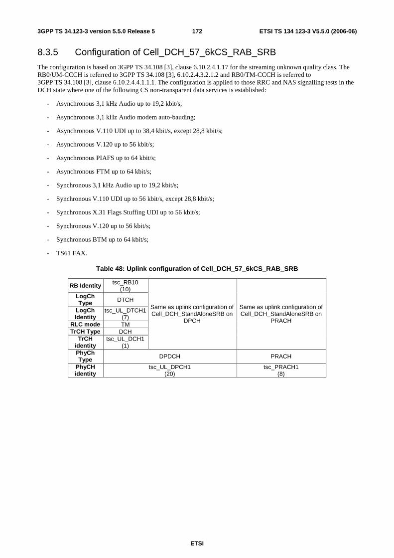
ETSI
ETSI TS 134 123-3 V5.5.0 (2006-06) 1723GPP TS 34.123-3 version 5.5.0 Release 5
8.3.5 Configuration of Cell_DCH_57_6kCS_RAB_SRB
The configuration is based on 3GPP TS 34.108 [3], clause 6.10.2.4.1.17 for the streaming unknown quality class. The RB0/UM-CCCH is referred to 3GPP TS 34.108 [3], 6.10.2.4.3.2.1.2 and RB0/TM-CCCH is referred to 3GPP TS 34.108 [3], clause 6.10.2.4.4.1.1.1. The configuration is applied to those RRC and NAS signalling tests in the DCH state where one of the following CS non-transparent data services is established:
- Asynchronous 3,1 kHz Audio up to 19,2 kbit/s;
- Asynchronous 3,1 kHz Audio modem auto-bauding;
- Asynchronous V.110 UDI up to 38,4 kbit/s, except 28,8 kbit/s;
- Asynchronous V.120 up to 56 kbit/s;
- Asynchronous PIAFS up to 64 kbit/s;
- Asynchronous FTM up to 64 kbit/s;
- Synchronous 3,1 kHz Audio up to 19,2 kbit/s;
- Synchronous V.110 UDI up to 56 kbit/s, except 28,8 kbit/s;
- Synchronous X.31 Flags Stuffing UDI up to 56 kbit/s;
- Synchronous V.120 up to 56 kbit/s;
- Synchronous BTM up to 64 kbit/s;
- TS61 FAX.
Table 48: Uplink configuration of Cell_DCH_57_6kCS_RAB_SRB
RB Identity tsc_RB10 (10)
LogCh Type DTCH
LogCh Identity
tsc_UL_DTCH1 (7)
RLC mode TM TrCH Type DCH
TrCH identity
tsc_UL_DCH1 (1)
Same as uplink configuration of Cell_DCH_StandAloneSRB on
DPCH
Same as uplink configuration of Cell_DCH_StandAloneSRB on
PRACH
PhyCh Type DPDCH PRACH
PhyCH identity
tsc_UL_DPCH1 (20)
tsc_PRACH1 (8)
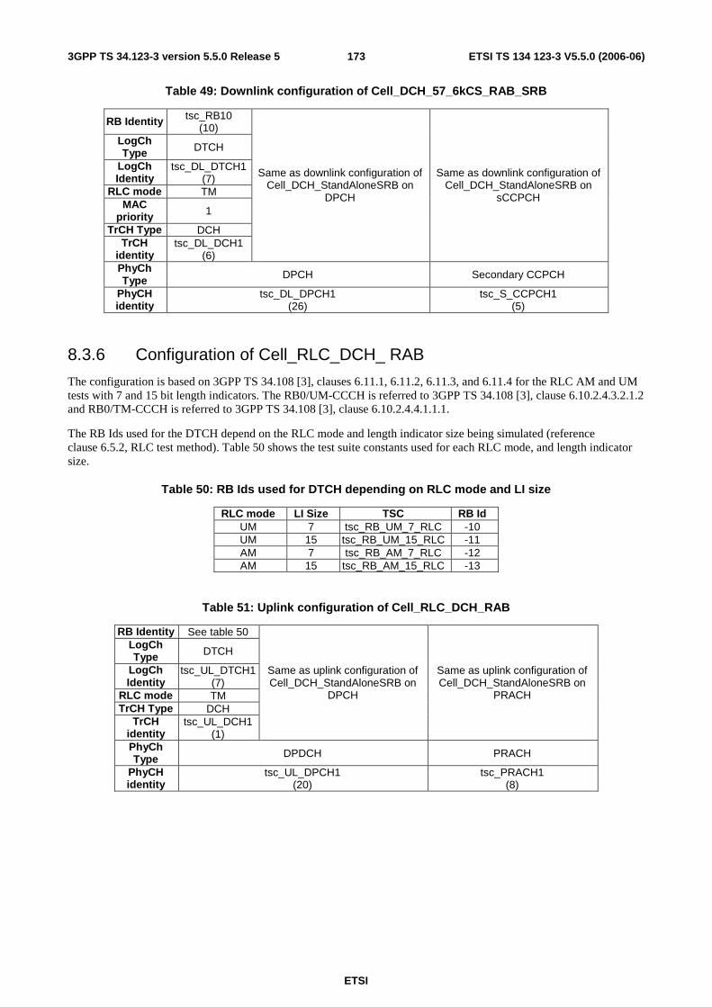
ETSI
ETSI TS 134 123-3 V5.5.0 (2006-06) 1733GPP TS 34.123-3 version 5.5.0 Release 5
Table 49: Downlink configuration of Cell_DCH_57_6kCS_RAB_SRB
RB Identity tsc_RB10 (10)
LogCh Type DTCH
LogCh Identity
tsc_DL_DTCH1 (7)
RLC mode TM MAC
priority 1
TrCH Type DCH TrCH
identity tsc_DL_DCH1
(6)
Same as downlink configuration of Cell_DCH_StandAloneSRB on
DPCH
Same as downlink configuration of Cell_DCH_StandAloneSRB on
sCCPCH
PhyCh Type DPCH Secondary CCPCH
PhyCH identity
tsc_DL_DPCH1 (26)
tsc_S_CCPCH1 (5)
8.3.6 Configuration of Cell_RLC_DCH_ RAB
The configuration is based on 3GPP TS 34.108 [3], clauses 6.11.1, 6.11.2, 6.11.3, and 6.11.4 for the RLC AM and UM tests with 7 and 15 bit length indicators. The RB0/UM-CCCH is referred to 3GPP TS 34.108 [3], clause 6.10.2.4.3.2.1.2 and RB0/TM-CCCH is referred to 3GPP TS 34.108 [3], clause 6.10.2.4.4.1.1.1.
The RB Ids used for the DTCH depend on the RLC mode and length indicator size being simulated (reference clause 6.5.2, RLC test method). Table 50 shows the test suite constants used for each RLC mode, and length indicator size.
Table 50: RB Ids used for DTCH depending on RLC mode and LI size
RLC mode LI Size TSC RB Id UM 7 tsc_RB_UM_7_RLC -10 UM 15 tsc_RB_UM_15_RLC -11 AM 7 tsc_RB_AM_7_RLC -12 AM 15 tsc_RB_AM_15_RLC -13
Table 51: Uplink configuration of Cell_RLC_DCH_RAB
RB Identity See table 50 LogCh Type DTCH
LogCh Identity
tsc_UL_DTCH1 (7)
RLC mode TM TrCH Type DCH
TrCH identity
tsc_UL_DCH1 (1)
Same as uplink configuration of Cell_DCH_StandAloneSRB on
DPCH
Same as uplink configuration of Cell_DCH_StandAloneSRB on
PRACH
PhyCh Type DPDCH PRACH
PhyCH identity
tsc_UL_DPCH1 (20)
tsc_PRACH1 (8)
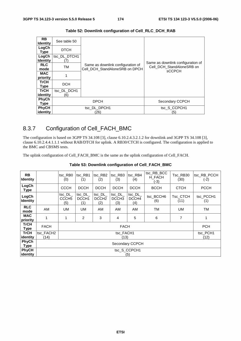
ETSI
ETSI TS 134 123-3 V5.5.0 (2006-06) 1743GPP TS 34.123-3 version 5.5.0 Release 5
Table 52: Downlink configuration of Cell_RLC_DCH_RAB
RB Identity See table 50
LogCh Type DTCH
LogCh Identity
tsc_DL_DTCH1 (7)
RLC mode TM
MAC priority 1
TrCH Type DCH
TrCH identity
tsc_DL_DCH1 (6)
Same as downlink configuration of Cell_DCH_StandAloneSRB on DPCH
Same as downlink configuration of Cell_DCH_StandAloneSRB on
sCCPCH
PhyCh Type DPCH Secondary CCPCH
PhyCH identity
tsc_DL_DPCH1 (26)
tsc_S_CCPCH1 (5)
8.3.7 Configuration of Cell_FACH_BMC
The configuration is based on 3GPP TS 34.108 [3], clause 6.10.2.4.3.2.1.2 for downlink and 3GPP TS 34.108 [3], clause 6.10.2.4.4.1.1.1 without RAB/DTCH for uplink. A RB30/CTCH is configured. The configuration is applied to the BMC and CBSMS tests.
The uplink configuration of Cell_FACH_BMC is the same as the uplink configuration of Cell_FACH.
Table 53: Downlink configuration of Cell_FACH_BMC
RB Identity tsc_RB0
(0) tsc_RB1
(1) tsc_RB2
(2) tsc_RB3
(3) tsc_RB4
(4)
tsc_RB_BCCH_FACH
(-3)
Tsc_RB30 (30)
tsc_RB_PCCH (-2)
LogCh Type CCCH DCCH DCCH DCCH DCCH BCCH CTCH PCCH
LogCh Identity
tsc_DL_CCCH5
(5)
tsc_DL_DCCH1
(1)
tsc_DL_DCCH2
(2)
tsc_DL_DCCH3
(3)
tsc_DL_DCCH4
(4)
tsc_BCCH6 (6)
Tsc_CTCH (11)
tsc_PCCH1 (1)
RLC mode AM UM UM AM AM AM TM UM TM
MAC priority 1 1 2 3 4 5 6 7 1
TrCH Type FACH FACH PCH
TrCH identity
tsc_FACH2 (14)
tsc_FACH1 (13)
tsc_PCH1 (12)
PhyCh Type Secondary CCPCH
PhyCH identity
tsc_S_CCPCH1 (5)

ETSI
ETSI TS 134 123-3 V5.5.0 (2006-06) 1753GPP TS 34.123-3 version 5.5.0 Release 5
8.3.8 Configuration of PS Cell_DCH_64kPS_RAB_SRB and Cell_PDCP_AM_RAB
The configuration is based on 3GPP TS 34.108 [3], clause 6.10.2.4.1.26. The RB0/UM-CCCH is referred to 3GPP TS 34.108 [3], clause 6.10.2.4.3.2.1.2 and RB0/TM-CCCH is referred to 3GPP TS 34.108 [3], clause 6.10.2.4.4.1.1.1. The configuration is applied to those RRC and NAS signalling tests in the DCH state where a PS RAB on DTCH is setup for the interactive or background service class. The configuration is applied to PDCP test cases in acknowledge mode.
Table 54: Uplink configuration of PS Cell_DCH_64kPS_RAB_SRB SRB and Cell_PDCP_AM_RAB
RB Identity tsc_RB20 (20)
LogCh Type DTCH
LogCh Identity
tsc_UL_DTCH1 (7)
RLC mode AM TrCH Type DCH
TrCH identity tsc_UL_DCH
1 (1)
Same as uplink configuration of Cell_DCH_StandAloneSRB on
DPCH
Same as uplink configuration of Cell_DCH_StandAloneSRB on
PRACH
PhyCh Type DPDCH PRACH PhyCH identity
tsc_UL_DPCH1 (20)
tsc_PRACH1 (8)
Table 55: Downlink configuration of PS Cell_DCH_64kPS_RAB_SRB SRB and Cell_PDCP_AM_RAB
RB Identity tsc_RB20 (20)
LogCh Type DTCH
LogCh Identity
tsc_DL_DTCH1 (7)
RLC mode AM MAC
priority 1
TrCH Type DCH
TrCH identity
tsc_DL_DCH1
(6)
Same as downlink configuration of Cell_DCH_StandAloneSRB on
DPCH
Same as downlink configuration of Cell_DCH_StandAloneSRB on
sCCPCH
PhyCh Type DPCH Secondary CCPCH
PhyCH identity
tsc_DL_DPCH1 (26)
tsc_S_CCPCH1 (5)
8.3.9 Configuration of Cell_Two_DTCH
The configuration is based on 3GPP TS 34.108 [3], clauses 6.10.2.4.1.6 to 6.10.2.4.1.11. The RB0/UM-CCCH is referred to 3GPP TS 34.108 [3], clause 6.10.2.4.3.2.1.2 and RB0/TM-CCCH is referred to 3GPP TS 34.108 [3], clause 6.10.2.4.4.1.1.1. The configuration is applied to RB tests.

ETSI
ETSI TS 134 123-3 V5.5.0 (2006-06) 1763GPP TS 34.123-3 version 5.5.0 Release 5
Table 56: Uplink configuration of Cell_Two_DTCH
RB Identity tsc_RB10 (10)
tsc_RB11 (11)
LogCh Type DTCH DTCH
LogCh Identity
tsc_UL_DTCH1
(7)
tsc_UL_DTCH2
(8) RLC mode TM TM TrCH Type DCH DCH
TrCH identity
tsc_UL_DCH1 (1)
tsc_UL_DCH2 (2)
Same as uplink configuration of Cell_DCH_StandAloneSRB on DPCH
Same as uplink configuration of Cell_DCH_StandAloneSRB on
PRACH
PhyCh Type DPCH PRACH PhyCH identity
tsc_UL_DPDCH1 (20)
tsc_PRACH1 (8)
Table 57: Downlink configuration of Cell_Two_DTCH
RB Identity tsc_RB10 (10)
tsc_RB11 (11)
LogCh Type DTCH DTCH
LogCh Identity tsc_DL_DTCH1 (7)
tsc_DL_DTCH2 (8)
RLC mode TM TM MAC priority 1 1 TrCH Type DCH DCH
TrCH identity tsc_DL_DCH1 (6)
tsc_DL_DCH2 (7)
Same as downlink configuration of Cell_DCH_StandAloneSRB on
DPCH
Same as downlink configuration of Cell_DCH_StandAloneSRB on
sCCPCH
PhyCh Type DPCH Secondary CCPCH
PhyCH identity tsc_DL_DPCH1 (26)
tsc_S_CCPCH1 (5)
8.3.10 Configuration of Cell_Single_DTCH (CS)
The configuration is based on 3GPP TS 34.108 [3], clauses 6.10.2.4.1.12 to 6.10.2.4.1.22. The RB0/UM-CCCH is referred to 3GPP TS 34.108 [3], clause 6.10.2.4.3.2.1.2 and RB0/TM-CCCH is referred to 3GPP TS 34.108 [3], clause 6.10.2.4.4.1.1.1. The configuration is applied to RB tests.
Table 58: Uplink configuration of Cell_Single_DTCH (CS)
RB Identity tsc_RB10 (10)
LogCh Type DTCH LogCh Identity
tsc_UL_DTCH1 (7)
RLC mode TM TrCH Type DCH
TrCH identity
tsc_UL_DCH1 (1)
Same as uplink configuration of Cell_DCH_StandAloneSRB on
DPCH
Same as uplink configuration of Cell_DCH_StandAloneSRB on
PRACH
PhyCh Type DPDCH PRACH PhyCH identity
tsc_UL_DPCH1 (20)
tsc_PRACH1 (8)

ETSI
ETSI TS 134 123-3 V5.5.0 (2006-06) 1773GPP TS 34.123-3 version 5.5.0 Release 5
Table 59: Downlink configuration of Cell_Single_DTCH (CS)
RB Identity tsc_RB10 (10)
LogCh Type DTCH
LogCh Identity tsc_DL_DTCH1 (7)
RLC mode TM MAC priority 1 TrCH Type DCH
TrCH identity tsc_DL_DCH1 (6)
Same as downlink configuration of Cell_DCH_StandAloneSRB on
DPCH
Same as downlink configuration of Cell_DCH_StandAloneSRB on
sCCPCH
PhyCh Type DPCH Secondary CCPCH
PhyCH identity tsc_DL_DPCH1 (26)
tsc_S_CCPCH1 (5)
8.3.11 Configuration of PS Cell_PDCP_UM_RAB
The configuration is based on 3GPP TS 34.108 [3], clause 6.10.2.4.1.26. The RB0/UM-CCCH is referred to 3GPP TS 34.108 [3], clause 6.10.2.4.3.2.1.2 and RB0/TM-CCCH is referred to 3GPP TS 34.108 [3], clause 6.10.2.4.4.1.1.1. The configuration is applied to PDCP test cases in unacknowledge mode.
Table 60: Uplink configuration of PS Cell_PDCP_UM_RAB
RB Identity tsc_RB21 (21)
LogCh Type DTCH LogCh Identity
tsc_UL_DTCH1 (7)
RLC mode UM TrCH Type DCH
TrCH identity tsc_UL_DCH1 (1)
Same as uplink configuration of Cell_DCH_StandAloneSRB on
DPCH
Same as uplink configuration of Cell_DCH_StandAloneSRB on
PRACH
PhyCh Type DPDCH PRACH PhyCH identity
tsc_UL_DPCH1 (20)
tsc_PRACH1 (8)
Table 61: Downlink configuration of PS Cell_PDCP_UM_RAB
RB Identity tsc_RB21 (21)
LogCh Type DTCH
LogCh Identity
tsc_DL_DTCH1 (7)
RLC mode UM MAC
priority 1
TrCH Type DCH TrCH
identity tsc_DL_DCH1
(6)
Same as downlink configuration of Cell_DCH_StandAloneSRB on
DPCH
Same as downlink configuration of Cell_DCH_StandAloneSRB on
sCCPCH
PhyCh Type DPCH Secondary CCPCH
PhyCH identity
tsc_DL_DPCH1 (26)
tsc_S_CCPCH1 (5)
8.3.12 Configuration of PS Cell_PDCP_AM_UM_RAB
The configuration is based on 3GPP TS 34.108 [3], clause 6.10.2.4.1.26. The RB0/UM-CCCH is referred to 3GPP TS 34.108 [3], clause 6.10.2.4.3.2.1.2 and RB0/TM-CCCH is referred to 3GPP TS 34.108 [3],
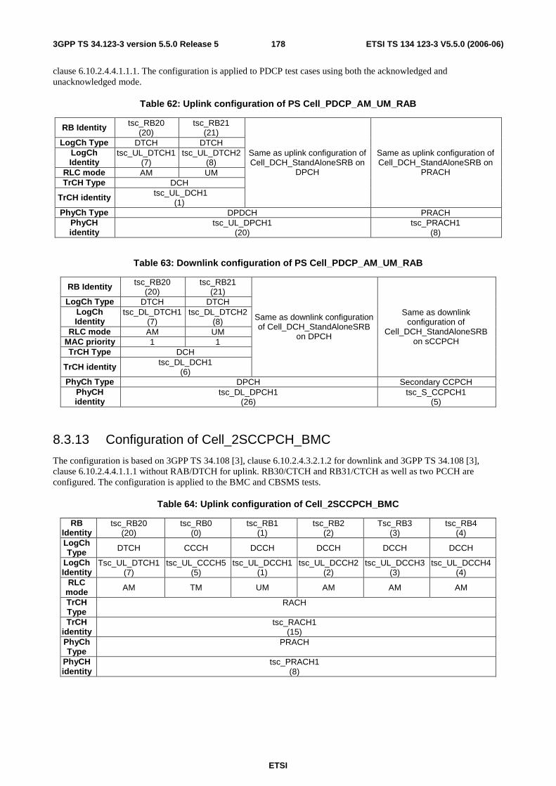
ETSI
ETSI TS 134 123-3 V5.5.0 (2006-06) 1783GPP TS 34.123-3 version 5.5.0 Release 5
clause 6.10.2.4.4.1.1.1. The configuration is applied to PDCP test cases using both the acknowledged and unacknowledged mode.
Table 62: Uplink configuration of PS Cell_PDCP_AM_UM_RAB
RB Identity tsc_RB20 (20)
tsc_RB21 (21)
LogCh Type DTCH DTCH LogCh Identity
tsc_UL_DTCH1 (7)
tsc_UL_DTCH2 (8)
RLC mode AM UM TrCH Type DCH
TrCH identity tsc_UL_DCH1 (1)
Same as uplink configuration of Cell_DCH_StandAloneSRB on
DPCH
Same as uplink configuration of Cell_DCH_StandAloneSRB on
PRACH
PhyCh Type DPDCH PRACH PhyCH identity
tsc_UL_DPCH1 (20)
tsc_PRACH1 (8)
Table 63: Downlink configuration of PS Cell_PDCP_AM_UM_RAB
RB Identity tsc_RB20 (20)
tsc_RB21 (21)
LogCh Type DTCH DTCH LogCh Identity
tsc_DL_DTCH1 (7)
tsc_DL_DTCH2 (8)
RLC mode AM UM MAC priority 1 1 TrCH Type DCH
TrCH identity tsc_DL_DCH1 (6)
Same as downlink configuration of Cell_DCH_StandAloneSRB
on DPCH
Same as downlink configuration of
Cell_DCH_StandAloneSRB on sCCPCH
PhyCh Type DPCH Secondary CCPCH PhyCH identity
tsc_DL_DPCH1 (26)
tsc_S_CCPCH1 (5)
8.3.13 Configuration of Cell_2SCCPCH_BMC
The configuration is based on 3GPP TS 34.108 [3], clause 6.10.2.4.3.2.1.2 for downlink and 3GPP TS 34.108 [3], clause 6.10.2.4.4.1.1.1 without RAB/DTCH for uplink. RB30/CTCH and RB31/CTCH as well as two PCCH are configured. The configuration is applied to the BMC and CBSMS tests.
Table 64: Uplink configuration of Cell_2SCCPCH_BMC
RB Identity
tsc_RB20 (20)
tsc_RB0 (0)
tsc_RB1 (1)
tsc_RB2 (2)
Tsc_RB3 (3)
tsc_RB4 (4)
LogCh Type DTCH CCCH DCCH DCCH DCCH DCCH
LogCh Identity
Tsc_UL_DTCH1 (7)
tsc_UL_CCCH5 (5)
tsc_UL_DCCH1 (1)
tsc_UL_DCCH2 (2)
tsc_UL_DCCH3 (3)
tsc_UL_DCCH4 (4)
RLC mode AM TM UM AM AM AM
TrCH Type
RACH
TrCH identity
tsc_RACH1 (15)
PhyCh Type
PRACH
PhyCH identity
tsc_PRACH1 (8)
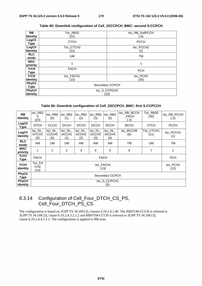
ETSI
ETSI TS 134 123-3 V5.5.0 (2006-06) 1793GPP TS 34.123-3 version 5.5.0 Release 5
Table 65: Downlink configuration of Cell_2SCCPCH_BMC: second S-CCPCH
RB Identity
Tsc_RB31 (31)
tsc_RB_2ndPCCH (-4)
LogCh Type CTCH PCCH
LogCh Identity
Tsc_CTCH2 (12)
tsc_PCCH2 (2)
RLC mode UM TM
MAC priority 1 1
TrCH Type
FACH PCH
TrCH identity
tsc_FACH1 (13)
tsc_PCH2 (30)
PhyCh Type Secondary CCPCH
PhyCH identity
tsc_S_CCPCH2 (10)
Table 66: Downlink configuration of Cell_2SCCPCH_BMC: first S-CCPCCH
RB Identity
tsc_RB20
(20)
tsc_RB0 (0)
tsc_RB1 (1)
tsc_RB2 (2)
tsc_RB3 (3)
tsc_RB4 (4)
tsc_RB_BCCH_FACH
(-3)
Tsc_RB30 (30) tsc_RB_PCCH
(-2)
LogCh Type DTCH CCCH DCCH DCCH DCCH DCCH BCCH CTCH PCCH
LogCh Identity
tsc_DL_DTCH1
(6)
tsc_DL_CCCH5
(5)
tsc_DL_DCCH1
(1)
tsc_DL_DCCH2
(2)
tsc_DL_DCCH3
(3)
tsc_DL_DCCH4
(4)
tsc_BCCH6 (6)
Tsc_CTCH1 (11)
tsc_PCCH1 (1)
RLC mode AM UM UM AM AM AM TM UM TM
MAC priority 1 1 2 3 4 5 6 7 1
TrCH Type FACH FACH PCH
TrCH identity
Tsc_FACH2 (14)
tsc_FACH1 (13)
tsc_PCH1 (12)
PhyCh Type Secondary CCPCH
PhyCH identity
tsc_S_CCPCH1 (5)
8.3.14 Configuration of Cell_Four_DTCH_CS_PS, Cell_Four_DTCH_PS_CS
The configuration is based on 3GPP TS 34.108 [3], clauses 6.10.2.4.1.40. The RB0/UM-CCCH is referred to 3GPP TS 34.108 [3], clause 6.10.2.4.3.2.1.2 and RB0/TM-CCCH is referred to 3GPP TS 34.108 [3], clause 6.10.2.4.4.1.1.1. The configuration is applied to RB tests.
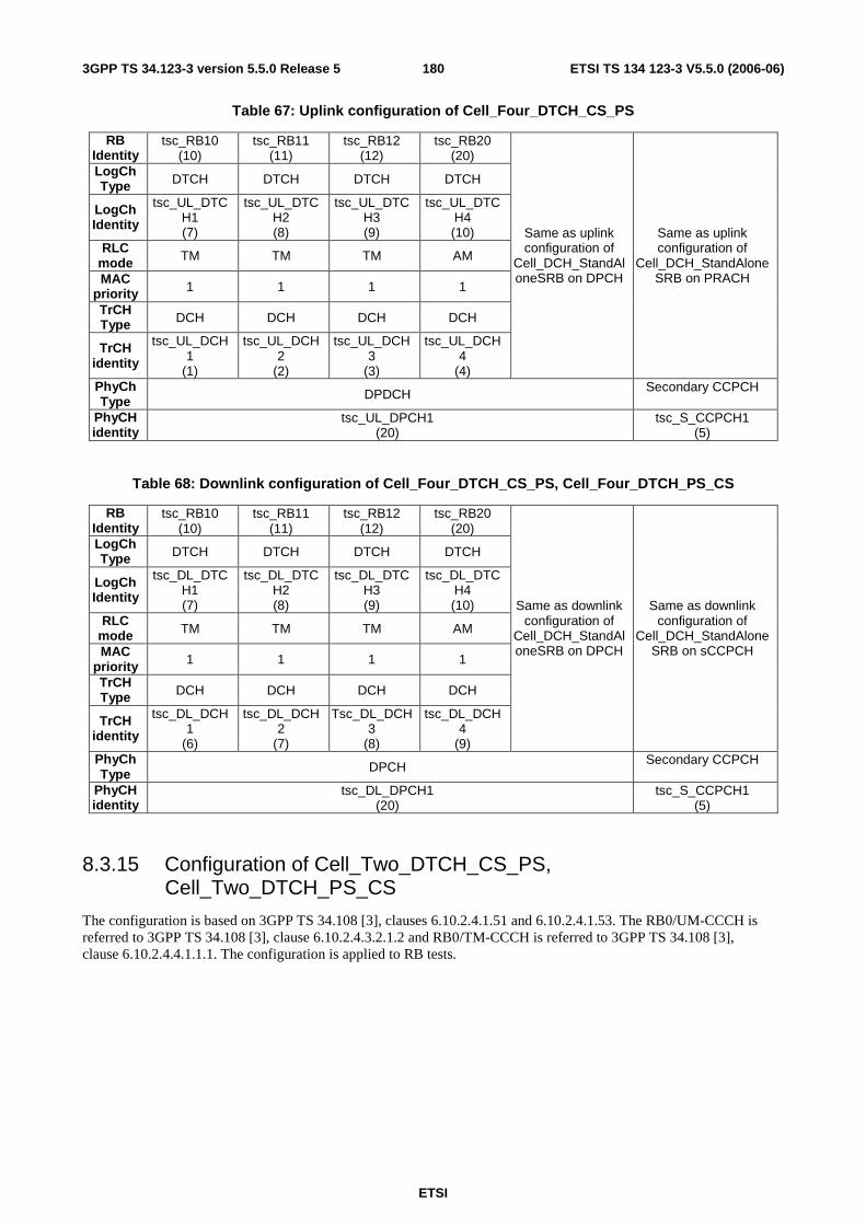
ETSI
ETSI TS 134 123-3 V5.5.0 (2006-06) 1803GPP TS 34.123-3 version 5.5.0 Release 5
Table 67: Uplink configuration of Cell_Four_DTCH_CS_PS
RB Identity
tsc_RB10 (10)
tsc_RB11 (11)
tsc_RB12 (12)
tsc_RB20 (20)
LogCh Type DTCH DTCH DTCH DTCH
LogCh Identity
tsc_UL_DTCH1 (7)
tsc_UL_DTCH2 (8)
tsc_UL_DTCH3 (9)
tsc_UL_DTCH4 (10)
RLC mode TM TM TM AM
MAC priority 1 1 1 1
TrCH Type DCH DCH DCH DCH
TrCH identity
tsc_UL_DCH1
(1)
tsc_UL_DCH2
(2)
tsc_UL_DCH3
(3)
tsc_UL_DCH4
(4)
Same as uplink configuration of
Cell_DCH_StandAloneSRB on DPCH
Same as uplink configuration of
Cell_DCH_StandAloneSRB on PRACH
PhyCh Type DPDCH Secondary CCPCH
PhyCH identity
tsc_UL_DPCH1 (20)
tsc_S_CCPCH1 (5)
Table 68: Downlink configuration of Cell_Four_DTCH_CS_PS, Cell_Four_DTCH_PS_CS
RB Identity
tsc_RB10 (10)
tsc_RB11 (11)
tsc_RB12 (12)
tsc_RB20 (20)
LogCh Type DTCH DTCH DTCH DTCH
LogCh Identity
tsc_DL_DTCH1 (7)
tsc_DL_DTCH2 (8)
tsc_DL_DTCH3 (9)
tsc_DL_DTCH4 (10)
RLC mode TM TM TM AM
MAC priority 1 1 1 1
TrCH Type DCH DCH DCH DCH
TrCH identity
tsc_DL_DCH1
(6)
tsc_DL_DCH2
(7)
Tsc_DL_DCH3
(8)
tsc_DL_DCH4
(9)
Same as downlink configuration of
Cell_DCH_StandAloneSRB on DPCH
Same as downlink configuration of
Cell_DCH_StandAloneSRB on sCCPCH
PhyCh Type DPCH Secondary CCPCH
PhyCH identity
tsc_DL_DPCH1 (20)
tsc_S_CCPCH1 (5)
8.3.15 Configuration of Cell_Two_DTCH_CS_PS, Cell_Two_DTCH_PS_CS
The configuration is based on 3GPP TS 34.108 [3], clauses 6.10.2.4.1.51 and 6.10.2.4.1.53. The RB0/UM-CCCH is referred to 3GPP TS 34.108 [3], clause 6.10.2.4.3.2.1.2 and RB0/TM-CCCH is referred to 3GPP TS 34.108 [3], clause 6.10.2.4.4.1.1.1. The configuration is applied to RB tests.

ETSI
ETSI TS 134 123-3 V5.5.0 (2006-06) 1813GPP TS 34.123-3 version 5.5.0 Release 5
Table 69:Uplink configuration of Cell_Two_DTCH_CS_PS, Cell_Two_DTCH_PS_CS
RB Identity tsc_RB10 (10)
tsc_RB20 (20)
LogCh Type DTCH DTCH LogCh Identity
tsc_UL_DTCH1 (7)
tsc_UL_DTCH2 (8)
RLC mode TM AM TrCH Type DCH DCH
TrCH identity
tsc_UL_DCH1 (1)
tsc_UL_DCH2 (2)
Same as uplink configuration of
Cell_DCH_StandAloneSRB on
DPCH
Same as uplink configuration of
Cell_DCH_StandAloneSRB on PRACH
PhyCh Type DPDCH PRACH PhyCH identity
tsc_UL_DPCH1 (20)
tsc_PRACH1 (8)
Table 70: Downlink configuration of Cell_Two_DTCH_CS_PS
RB Identity
tsc_RB10 (10)
tsc_RB20 (20)
LogCh Type DTCH DTCH
LogCh Identity
tsc_DL_DTCH1 (7)
tsc_DL_DTCH2 (8)
RLC mode TM AM
MAC priority 1 1
TrCH Type DCH DCH
TrCH identity
tsc_DL_DCH1 (6)
tsc_DL_DCH2 (7)
Same as downlink configuration of
Cell_DCH_StandAloneSRB on DPCH
Same as downlink configuration of
Cell_DCH_StandAloneSRB on sCCPCH
PhyCh Type DPCH Secondary CCPCH
PhyCH identity
tsc_DL_DPCH1 (20)
tsc_S_CCPCH1 (5)
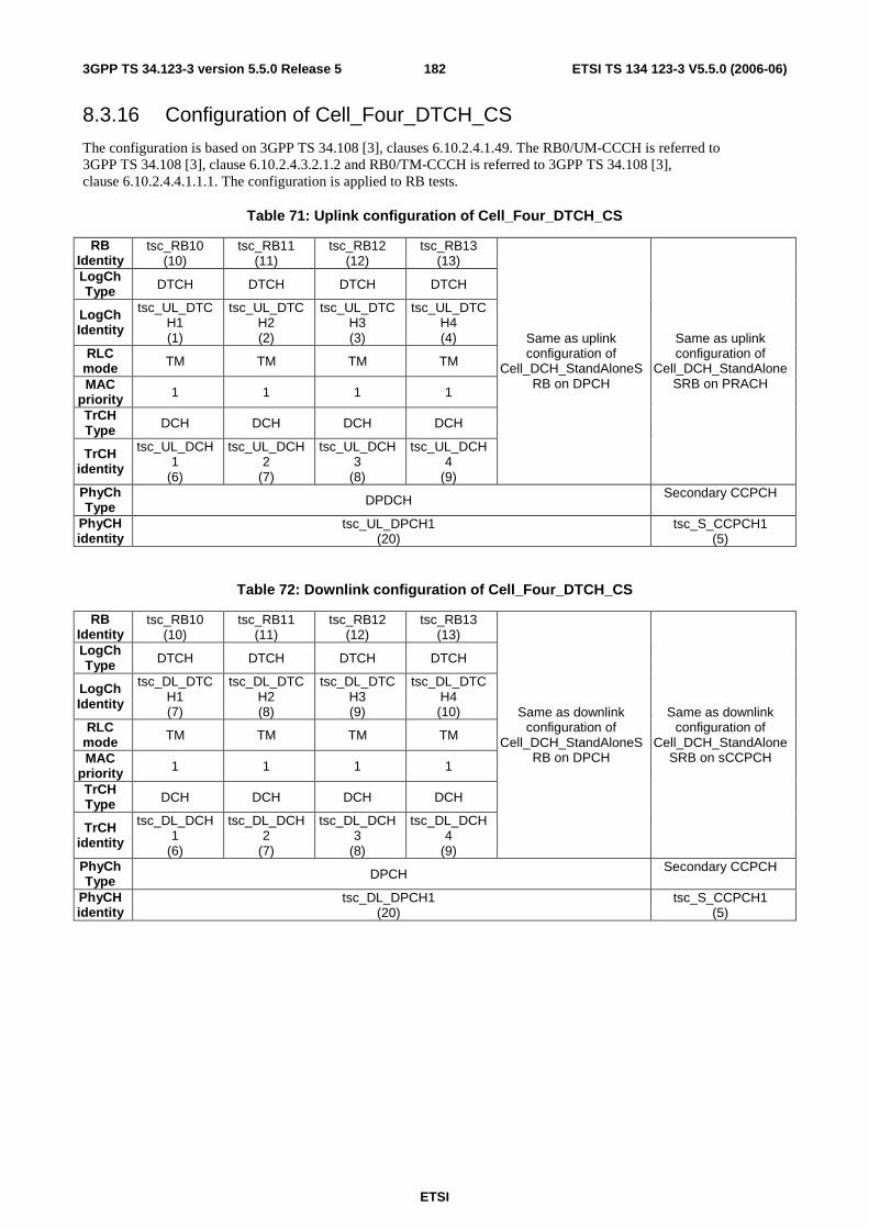
ETSI
ETSI TS 134 123-3 V5.5.0 (2006-06) 1823GPP TS 34.123-3 version 5.5.0 Release 5
8.3.16 Configuration of Cell_Four_DTCH_CS
The configuration is based on 3GPP TS 34.108 [3], clauses 6.10.2.4.1.49. The RB0/UM-CCCH is referred to 3GPP TS 34.108 [3], clause 6.10.2.4.3.2.1.2 and RB0/TM-CCCH is referred to 3GPP TS 34.108 [3], clause 6.10.2.4.4.1.1.1. The configuration is applied to RB tests.
Table 71: Uplink configuration of Cell_Four_DTCH_CS
RB Identity
tsc_RB10 (10)
tsc_RB11 (11)
tsc_RB12 (12)
tsc_RB13 (13)
LogCh Type DTCH DTCH DTCH DTCH
LogCh Identity
tsc_UL_DTCH1 (1)
tsc_UL_DTCH2 (2)
tsc_UL_DTCH3 (3)
tsc_UL_DTCH4 (4)
RLC mode TM TM TM TM
MAC priority 1 1 1 1
TrCH Type DCH DCH DCH DCH
TrCH identity
tsc_UL_DCH1
(6)
tsc_UL_DCH2
(7)
tsc_UL_DCH3
(8)
tsc_UL_DCH4
(9)
Same as uplink configuration of
Cell_DCH_StandAloneSRB on DPCH
Same as uplink configuration of
Cell_DCH_StandAloneSRB on PRACH
PhyCh Type DPDCH Secondary CCPCH
PhyCH identity
tsc_UL_DPCH1 (20)
tsc_S_CCPCH1 (5)
Table 72: Downlink configuration of Cell_Four_DTCH_CS
RB Identity
tsc_RB10 (10)
tsc_RB11 (11)
tsc_RB12 (12)
tsc_RB13 (13)
LogCh Type DTCH DTCH DTCH DTCH
LogCh Identity
tsc_DL_DTCH1 (7)
tsc_DL_DTCH2 (8)
tsc_DL_DTCH3 (9)
tsc_DL_DTCH4 (10)
RLC mode TM TM TM TM
MAC priority 1 1 1 1
TrCH Type DCH DCH DCH DCH
TrCH identity
tsc_DL_DCH1
(6)
tsc_DL_DCH2
(7)
tsc_DL_DCH3
(8)
tsc_DL_DCH4
(9)
Same as downlink configuration of
Cell_DCH_StandAloneSRB on DPCH
Same as downlink configuration of
Cell_DCH_StandAloneSRB on sCCPCH
PhyCh Type DPCH Secondary CCPCH
PhyCH identity
tsc_DL_DPCH1 (20)
tsc_S_CCPCH1 (5)
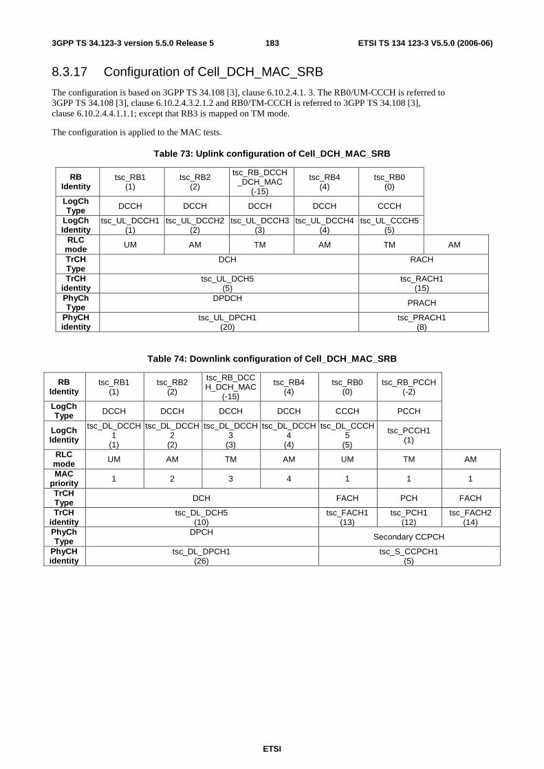
ETSI
ETSI TS 134 123-3 V5.5.0 (2006-06) 1833GPP TS 34.123-3 version 5.5.0 Release 5
8.3.17 Configuration of Cell_DCH_MAC_SRB
The configuration is based on 3GPP TS 34.108 [3], clause 6.10.2.4.1. 3. The RB0/UM-CCCH is referred to 3GPP TS 34.108 [3], clause 6.10.2.4.3.2.1.2 and RB0/TM-CCCH is referred to 3GPP TS 34.108 [3], clause 6.10.2.4.4.1.1.1; except that RB3 is mapped on TM mode.
The configuration is applied to the MAC tests.
Table 73: Uplink configuration of Cell_DCH_MAC_SRB
RB Identity
tsc_RB1 (1)
tsc_RB2 (2)
tsc_RB_DCCH_DCH_MAC
(-15)
tsc_RB4 (4)
tsc_RB0 (0)
LogCh Type DCCH DCCH DCCH DCCH CCCH
LogCh Identity
tsc_UL_DCCH1 (1)
tsc_UL_DCCH2 (2)
tsc_UL_DCCH3 (3)
tsc_UL_DCCH4 (4)
tsc_UL_CCCH5 (5)
RLC mode UM AM TM AM TM AM
TrCH Type
DCH
RACH
TrCH identity
tsc_UL_DCH5 (5)
tsc_RACH1 (15)
PhyCh Type
DPDCH PRACH
PhyCH identity
tsc_UL_DPCH1 (20)
tsc_PRACH1 (8)
Table 74: Downlink configuration of Cell_DCH_MAC_SRB
RB Identity
tsc_RB1 (1)
tsc_RB2 (2)
tsc_RB_DCCH_DCH_MAC
(-15)
tsc_RB4 (4)
tsc_RB0 (0)
tsc_RB_PCCH (-2)
LogCh Type DCCH DCCH DCCH DCCH CCCH PCCH
LogCh Identity
tsc_DL_DCCH1
(1)
tsc_DL_DCCH2
(2)
tsc_DL_DCCH3
(3)
tsc_DL_DCCH4
(4)
tsc_DL_CCCH5
(5)
tsc_PCCH1 (1)
RLC mode UM AM TM AM UM TM AM
MAC priority 1 2 3 4 1 1 1
TrCH Type DCH FACH PCH FACH
TrCH identity
tsc_DL_DCH5 (10)
tsc_FACH1 (13)
tsc_PCH1 (12)
tsc_FACH2 (14)
PhyCh Type
DPCH Secondary CCPCH
PhyCH identity
tsc_DL_DPCH1 (26)
tsc_S_CCPCH1 (5)

ETSI
ETSI TS 134 123-3 V5.5.0 (2006-06) 1843GPP TS 34.123-3 version 5.5.0 Release 5
8.3.18 Configuration of Cell_FACH_MAC_SRB
The configuration is based on 3GPP TS 34.108 [3], clause 6.10.2.4.3.2.1.2 for downlink and 3GPP TS 34.108 [3], clause 6.10.2.4.4.1.1.1 for uplink; except that RB3 is mapped on TM mode.
The configuration is applied to the MAC tests.
Table 75: Uplink configuration of Cell_FACH_MAC_SRB
RB Identity
tsc_RB20 (20)
tsc_RB0 (0)
tsc_RB1 (1)
tsc_RB2 (2)
tsc_RB_DCCH_FACH_MAC
(-14)
tsc_RB4 (4)
LogCh Type DTCH CCCH DCCH DCCH DCCH DCCH
LogCh Identity
Tsc_UL_DTCH1
(7)
tsc_UL_CCCH5
(5)
tsc_UL_DCCH1
(1)
tsc_UL_DCCH2
(2)
tsc_UL_DCCH3 (3)
tsc_UL_DCCH4
(4) RLC
mode AM TM UM AM TM AM
TrCH Type RACH
TrCH identity
tsc_RACH1 (15)
PhyCh Type PRACH
PhyCH identity
tsc_PRACH1 (8)
Table 76: Downlink configuration of Cell_FACH_MAC_SRB
RB Identity
tsc_RB20 (20)
tsc_RB0 (0)
tsc_RB1 (1)
tsc_RB2 (2)
tsc_RB_DCCH_FACH_
MAC (-14)
tsc_RB4 (4)
tsc_RB_BCCH_FACH
(-3)
tsc_RB_PCCH (-2)
LogCh Type DTCH CCCH DCCH DCCH DCCH DCCH BCCH PCCH
LogCh Identity
tsc_DL_DTCH1 (6)
tsc_DL_CCCH5 (5)
tsc_DL_DCCH1 (1)
tsc_DL_DCCH2 (2)
tsc_DL_DCCH3 (3)
tsc_DL_DCCH4 (4)
tsc_BCCH6 (6) tsc_PCCH1
(1)
RLC mode AM UM UM AM TM AM TM TM
MAC priority 1 1 2 3 4 5 6 1
TrCH Type FACH FACH PCH
TrCH identity
tsc_FACH2 (14)
tsc_FACH1 (13)
tsc_PCH1 (12)
PhyCh Type Secondary CCPCH
PhyCH identity
tsc_S_CCPCH1 (5)

ETSI
ETSI TS 134 123-3 V5.5.0 (2006-06) 1853GPP TS 34.123-3 version 5.5.0 Release 5
8.3.19 Configuration of Cell_FACH_MAC_SRB0
The configuration is based on 3GPP TS 34.108 [3], clause 6.10.2.4.3.2.1.2 for downlink and 3GPP TS 34.108 [3], clause 6.10.2.4.4.1.1.1 for uplink; except that the downlink SRB0 is mapped on TM mode.
The configuration is applied to the MAC tests.
The uplink configuration of Cell_FACH_MAC_SRB0 is the same as the uplink configuration of Cell_FACH.
Table 77: Downlink configuration of Cell_FACH_MAC_SRB0
RB Identity
tsc_RB20 (20)
tsc_RB_CCCH_FACH_
MAC (-18)
tsc_RB1 (1)
tsc_RB2 (2)
tsc_RB3 (3)
tsc_RB4 (4)
tsc_RB_BCCH_FACH
(-3)
tsc_RB_PCCH (-2)
LogCh Type DTCH CCCH DCCH DCCH DCCH DCCH BCCH PCCH
LogCh Identity
tsc_DL_DTCH1 (6)
tsc_DL_CCCH5 (5)
tsc_DL_DCCH1 (1)
tsc_DL_DCCH2 (2)
tsc_DL_DCCH3 (3)
tsc_DL_DCCH4 (4)
tsc_BCCH6 (6)
tsc_PCCH1 (1)
RLC mode AM TM UM AM AM AM TM TM
MAC priority 1 1 2 3 4 5 6 1
TrCH Type FACH FACH PCH
TrCH identity
tsc_FACH2 (14)
tsc_FACH1 (13)
tsc_PCH1 (12)
PhyCh Type Secondary CCPCH
PhyCH identity
tsc_S_CCPCH1 (5)

ETSI
ETSI TS 134 123-3 V5.5.0 (2006-06) 1863GPP TS 34.123-3 version 5.5.0 Release 5
8.3.20 Configuration of Cell_FACH_2_SCCPCH_StandAlonePCH
The configuration is based on 3GPP TS 34.108 [3], clause 6.10.2.4.3.2.1.2 for downlink and 3GPP TS 34.108 [3] except the mapping of PCH, clause 6.10.2.4.4.1.1.1 for uplink.
The configuration is applied to the RAB tests.
The uplink configuration of Cell_FACH_2_SCCPCH_StandAlonePCH is the same as the uplink configuration of Cell_FACH.
Table 78: Downlink configuration of Cell_FACH_2_SCCPCH_StandAlonePCH
RB Identity
tsc_RB20 (20)
tsc_RB0 (0)
tsc_RB1 (1)
tsc_RB2 (2)
tsc_RB3 (3)
tsc_RB4 (4)
tsc_RB_BCCH_FACH
(-3)
tsc_RB_PCCH2 (-4)
LogCh Type DTCH CCCH DCCH DCCH DCCH DCCH BCCH PCCH
LogCh Identity
tsc_DL_DTCH1 (6)
tsc_DL_CCCH5 (5)
tsc_DL_DCCH1 (1)
tsc_DL_DCCH2 (2)
tsc_DL_DCCH3 (3)
tsc_DL_DCCH4 (4)
tsc_BCCH6 (6) tsc_PCCH1
(1)
RLC mode AM UM UM AM AM AM TM TM
MAC priority 1 1 2 3 4 5 6 1
TrCH Type FACH FACH PCH
TrCH identity
tsc_FACH2 (14)
tsc_FACH1 (13)
tsc_PCH1 (12)
PhyCh Type Secondary CCPCH Secondary
CCPCH
PhyCH identity
tsc_S_CCPCH2 (10)
tsc_S_CCPCH1 (5)
8.3.21 Configuration of PS Cell_DCH_2AM_PS
The configuration is based on 3GPP TS 34.108 [3], clauses 6.10.2.4.1.26 and 6.10.2.4.1.57. The RB0/UM-CCCH is referred to 3GPP TS 34.108 [3], clause 6.10.2.4.3.2.1.2 with 2 AM RAB and RB0/TM-CCCH is referred to 3GPP TS 34.108 [3], clause 6.10.2.4.4.1.1.1. The configuration is applied to MAC and RAB test cases.
Table 79: Uplink configuration of Cell_DCH_ 2AM_PS
RB Identity tsc_RB20 (20)
tsc_RB22 (22)
LogCh Type DTCH DTCH
LogCh Identity
tsc_UL_DTCH1
(7)
tsc_UL_DTCH2
(8) RLC mode AM AM TrCH Type DCH
TrCH identity tsc_UL_DCH1 (1)
Same as uplink configuration of Cell_DCH_StandAloneSRB on
DPCH
Same as uplink configuration of Cell_DCH_StandAloneSRB on
PRACH
PhyCh Type DPDCH PRACH PhyCH identity
tsc_UL_DPCH1 (20)
tsc_PRACH1 (8)

ETSI
ETSI TS 134 123-3 V5.5.0 (2006-06) 1873GPP TS 34.123-3 version 5.5.0 Release 5
Table 80: Downlink configuration of Cell_DCH_2AM_PS
RB Identity tsc_RB20 (20)
tsc_RB22 (22)
LogCh Type DTCH DTCH
LogCh Identity
tsc_DL_DTCH1
(7)
tsc_DL_DTCH2
(8) RLC mode AM AM
MAC priority 1 1 TrCH Type DCH
TrCH identity tsc_DL_DCH1 (6)
Same as downlink configuration of
Cell_DCH_StandAloneSRB on DPCH
Same as downlink configuration of Cell_DCH_StandAloneSRB on
sCCPCH
PhyCh Type DPCH Secondary CCPCH PhyCH identity
tsc_DL_DPCH1 (26)
tsc_S_CCPCH1 (5)
8.3.22 Configuration of PS Cell_DCH_2_PS_Call
The configuration is based on 3GPP TS 34.108 [3], clauses 6.10.2.4.1.56 and 6.10.2.4.1.58. The RB0/UM-CCCH is referred to 3GPP TS 34.108 [3], clause 6.10.2.4.3.2.1.2 and RB0/TM-CCCH is referred to 3GPP TS 34.108 [3], clause 6.10.2.4.4.1.1.1. The configuration is applied to RB tests.
Table 81: Uplink configuration of Cell_DCH_2_PS_Call
RB Identity tsc_RB20 (20)
tsc_RB22 (22)
LogCh Type DTCH DTCH
LogCh Identity
tsc_UL_DTCH1
(7)
tsc_UL_DTCH2
(8) RLC mode AM AM TrCH Type DCH DCH
TrCH identity
tsc_UL_DCH1 (1)
tsc_UL_DCH2
(2)
Same as uplink configuration of Cell_DCH_StandAloneSRB on
DPCH
Same as uplink configuration of Cell_DCH_StandAloneSRB on
PRACH
PhyCh Type DPDCH PRACH PhyCH identity
tsc_UL_DPCH1 (20)
tsc_PRACH1 (8)
Table 82: Downlink configuration of Cell_DCH_2_PS_Call
RB Identity tsc_RB20 (20)
tsc_RB22 (22)
LogCh Type DTCH DTCH
LogCh Identity
tsc_DL_DTCH1
(7)
tsc_DL_DTCH2
(8) RLC mode AM AM
MAC priority 1 1 TrCH Type DCH DCH
TrCH identity tsc_DL_DCH1 (6)
tsc_DL_DCH2(7)
Same as downlink configuration of
Cell_DCH_StandAloneSRB on DPCH
Same as downlink configuration of Cell_DCH_StandAloneSRB on
sCCPCH
PhyCh Type DPCH Secondary CCPCH PhyCH identity
tsc_DL_DPCH1 (26)
tsc_S_CCPCH1 (5)

ETSI
ETSI TS 134 123-3 V5.5.0 (2006-06) 1883GPP TS 34.123-3 version 5.5.0 Release 5
8.3.23 Configuration of Cell_FACH_3_SCCPCH_4_FACH_Cnfg1
The configuration is based on 3GPP TS 34.108 [3], clause 6.10.2.4.3.2 for downlink and 3GPP TS 34.108 [3], clause 6.10.2.4.4.1.1.1 for uplink. The configuration is applied to the RAB tests.
The uplink configuration of Cell_FACH_3_SCCPCH_4_FACH Cnfg1 is the same as the uplink configuration of Cell_FACH.
Table 83: Downlink configuration of Cell_FACH_3_SCCPCH_4_FACH_Cnfg1: 1st & 2nd S-CCPCH
RB Identity tsc_RB0 (0)
tsc_RB_BCCH_FACH
(-3) tsc_RB_PCCH (-2)
LogCh Type CCCH BCCH PCCH
LogCh Identity
tsc_DL_CCCH5
(5)
tsc_BCCH6 (6)
tsc_PCCH1 (1)
RLC mode UM TM TM MAC
priority 1 6 1
TrCH Type FACH FACH PCH TrCH
identity tsc_FACH2
(14) tsc_FACH1
(13) tsc_PCH1
(12) PhyCh Type Secondary CCPCH Secondary CCPCH
PhyCH identity
tsc_S_CCPCH2 (10)
tsc_S_CCPCH1 (5)
Table 84: Downlink configuration of Cell_FACH_3_SCCPCH_4_FACH_Cnfg1: 3rd S-CCPCH
RB Identity tsc_RB20 (20)
tsc_RB29 (29)
tsc_RB1 (1)
tsc_RB2 (2)
tsc_RB3 (3)
tsc_RB4 (4)
tsc_RB_BCCH_FACH_
RAB (-19)
LogCh Type DTCH CCCH DCCH DCCH DCCH DCCH BCCH
LogCh Identity
tsc_DL_DTCH1 (7)
tsc_DL_CCCH6
(6)
tsc_DL_DCCH1 (1)
tsc_DL_DCCH2 (2)
tsc_DL_DCCH3 (3)
tsc_DL_DCCH4 (4)
tsc_BCCH7 (7)
RLC mode AM UM UM AM AM AM TM MAC priority 1 1 2 3 4 5 6 TrCH Type FACH FACH
TrCH identity
tsc_FACH4 (17)
tsc_FACH3 (16)
PhyCh Type Secondary CCPCH PhyCH identity
tsc_S_CCPCH3 (13)
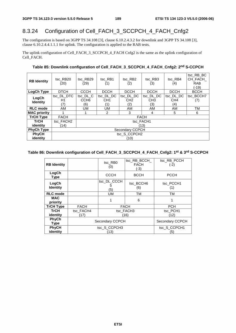
ETSI
ETSI TS 134 123-3 V5.5.0 (2006-06) 1893GPP TS 34.123-3 version 5.5.0 Release 5
8.3.24 Configuration of Cell_FACH_3_SCCPCH_4_FACH_Cnfg2
The configuration is based on 3GPP TS 34.108 [3], clause 6.10.2.4.3.2 for downlink and 3GPP TS 34.108 [3], clause 6.10.2.4.4.1.1.1 for uplink. The configuration is applied to the RAB tests.
The uplink configuration of Cell_FACH_3_SCCPCH_4_FACH Cnfg2 is the same as the uplink configuration of Cell_FACH.
Table 85: Downlink configuration of Cell_FACH_3_SCCPCH_4_FACH_Cnfg2: 2nd S-CCPCH
RB Identity tsc_RB20 (20)
tsc_RB29 (29)
tsc_RB1 (1)
tsc_RB2 (2)
tsc_RB3 (3)
tsc_RB4 (4)
tsc_RB_BCCH_FACH_
RAB (-19)
LogCh Type DTCH CCCH DCCH DCCH DCCH DCCH BCCH
LogCh Identity
tsc_DL_DTCH1 (7)
tsc_DL_CCCH6
(6)
tsc_DL_DCCH1 (1)
tsc_DL_DCCH2 (2)
tsc_DL_DCCH3 (3)
tsc_DL_DCCH4 (4)
tsc_BCCH7 (7)
RLC mode AM UM UM AM AM AM TM MAC priority 1 1 2 3 4 5 6 TrCH Type FACH FACH
TrCH identity
tsc_FACH2 (14)
tsc_FACH1 (13)
PhyCh Type Secondary CCPCH PhyCH identity
tsc_S_CCPCH2 (10)
Table 86: Downlink configuration of Cell_FACH_3_SCCPCH_4_FACH_Cnfg2: 1st & 3rd S-CCPCH
RB Identity tsc_RB0 (0)
tsc_RB_BCCH_FACH
(-3)
tsc_RB_PCCH (-2)
LogCh Type CCCH BCCH PCCH
LogCh Identity
tsc_DL_CCCH5
(5)
tsc_BCCH6 (6)
tsc_PCCH1 (1)
RLC mode UM TM TM MAC
priority 1 6 1
TrCH Type FACH FACH PCH TrCH
identity tsc_FACH4
(17) tsc_FACH3
(16) tsc_PCH1
(12) PhyCh Type Secondary CCPCH Secondary CCPCH
PhyCH identity
tsc_S_CCPCH3 (13)
tsc_S_CCPCH1 (5)
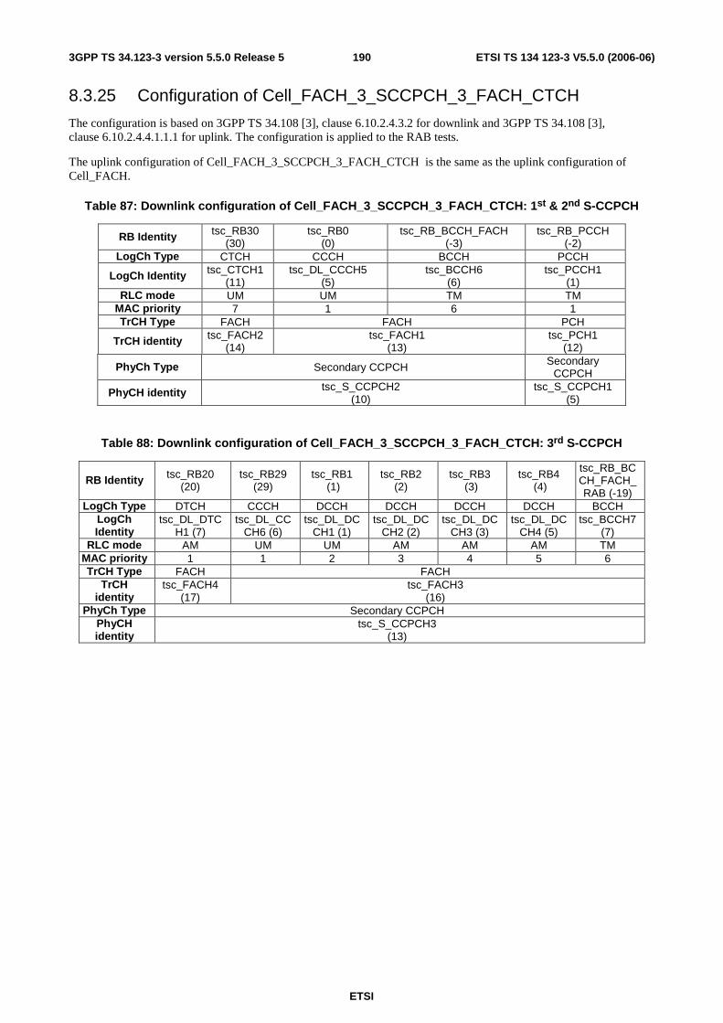
ETSI
ETSI TS 134 123-3 V5.5.0 (2006-06) 1903GPP TS 34.123-3 version 5.5.0 Release 5
8.3.25 Configuration of Cell_FACH_3_SCCPCH_3_FACH_CTCH
The configuration is based on 3GPP TS 34.108 [3], clause 6.10.2.4.3.2 for downlink and 3GPP TS 34.108 [3], clause 6.10.2.4.4.1.1.1 for uplink. The configuration is applied to the RAB tests.
The uplink configuration of Cell_FACH_3_SCCPCH_3_FACH_CTCH is the same as the uplink configuration of Cell_FACH.
Table 87: Downlink configuration of Cell_FACH_3_SCCPCH_3_FACH_CTCH: 1st & 2nd S-CCPCH
RB Identity tsc_RB30 (30)
tsc_RB0 (0)
tsc_RB_BCCH_FACH (-3)
tsc_RB_PCCH (-2)
LogCh Type CTCH CCCH BCCH PCCH
LogCh Identity tsc_CTCH1 (11)
tsc_DL_CCCH5 (5)
tsc_BCCH6 (6)
tsc_PCCH1 (1)
RLC mode UM UM TM TM MAC priority 7 1 6 1 TrCH Type FACH FACH PCH
TrCH identity tsc_FACH2 (14)
tsc_FACH1 (13)
tsc_PCH1 (12)
PhyCh Type Secondary CCPCH Secondary CCPCH
PhyCH identity tsc_S_CCPCH2 (10)
tsc_S_CCPCH1 (5)
Table 88: Downlink configuration of Cell_FACH_3_SCCPCH_3_FACH_CTCH: 3rd S-CCPCH
RB Identity tsc_RB20 (20)
tsc_RB29 (29)
tsc_RB1 (1)
tsc_RB2 (2)
tsc_RB3 (3)
tsc_RB4 (4)
tsc_RB_BCCH_FACH_RAB (-19)
LogCh Type DTCH CCCH DCCH DCCH DCCH DCCH BCCH LogCh Identity
tsc_DL_DTCH1 (7)
tsc_DL_CCCH6 (6)
tsc_DL_DCCH1 (1)
tsc_DL_DCCH2 (2)
tsc_DL_DCCH3 (3)
tsc_DL_DCCH4 (5)
tsc_BCCH7 (7)
RLC mode AM UM UM AM AM AM TM MAC priority 1 1 2 3 4 5 6 TrCH Type FACH FACH
TrCH identity
tsc_FACH4 (17)
tsc_FACH3 (16)
PhyCh Type Secondary CCPCH PhyCH identity
tsc_S_CCPCH3 (13)

ETSI
ETSI TS 134 123-3 V5.5.0 (2006-06) 1913GPP TS 34.123-3 version 5.5.0 Release 5
8.3.26 Configuration of PS Cell_DCH_DSCH_PS_RAB
The configuration is based on 3GPP TS 34.108 [3], clause 6.10.2.4.2.1. The RB0/UM-CCCH is referred to 3GPP TS 34.108 [3], clause 6.10.2.4.3.2.1.2 and RB0/TM-CCCH is referred to 3GPP TS 34.108 [3], clause 6.10.2.4.4.1.1.1. The configuration is applied to those RAB signalling tests where a PS RAB on DTCH is setup for the interactive or background service class is mapped on to DSCH.
The uplink configuration is same in clause 8.3.8.
Table 89a: Downlink configuration of PS Cell_DCH_DSCH_PS_RAB
RB Identity tsc_RB20 (20)
Same as downlink configuration of Cell_DCH_StandAloneSRB on
DPCH LogCh Type DTCH
LogCh Identity
tsc_DL_DTCH1 (7)
RLC mode AM MAC
priority 1
TrCH Type DSCH TrCH
identity tsc_DSCH1
(19)
Same as downlink configuration of Cell_DCH_StandAloneSRB on
sCCPCH
PhyCh Type PDSCH DPCH Secondary CCPCH
PhyCH identity
tsc_DL_PDSCH1 (16)
tsc_DL_DPCH1 (26)
tsc_S_CCPCH1 (5)
8.3.27 Configuration of Cell_DCH_DSCH_CS_PS
The configuration is based on 3GPP TS 34.108 [3], clauses 6.10.2.4.2.4. The RB0/UM-CCCH is referred to 3GPP TS 34.108 [3], clause 6.10.2.4.3.2.1.2 and RB0/TM-CCCH is referred to 3GPP TS 34.108 [3], clause 6.10.2.4.4.1.1.1. The configuration is applied to RB tests.
The Uplink configuration is similar to clause 8.3.14.
Table 97b: Downlink configuration of Cell_DCH_DSCH_CS_PS
RB Identity
tsc_RB10 (10)
tsc_RB11 (11)
tsc_RB12 (12)
tsc_RB20 (20)
LogCh Type DTCH DTCH DTCH DTCH
LogCh Identity
tsc_DL_DTCH1 (7)
tsc_DL_DTCH2 (8)
tsc_DL_DTCH3 (9)
tsc_DL_DTCH4 (10)
RLC mode TM TM TM AM
MAC priority 1 1 1 1
TrCH Type DCH DCH DCH DSCH
TrCH identity
tsc_DL_DCH1
(6)
tsc_DL_DCH2
(7)
Tsc_DL_DCH3
(8)
tsc_DL_DSCH1 (19)
Same as downlink configuration of
Cell_DCH_StandAloneSRB on
DPCH
Same as downlink configuration of
Cell_DCH_StandAloneSRB on sCCPCH
PhyCh Type DPCH PDSCH DPCH Secondary CCPCH
PhyCH identity
tsc_DL_DPCH1 (20)
tsc_DL_PDSCH1 (16)
tsc_DL_DPCH1 (20)
tsc_S_CCPCH1 (5)

ETSI
ETSI TS 134 123-3 V5.5.0 (2006-06) 1923GPP TS 34.123-3 version 5.5.0 Release 5
8.3.28 Configuration of Cell_FACH_2_SCCPCH_StandAlonePCH_2a
The configuration is based on 3GPP TS 34.108 [3], clause 6.10.2.4.3.2a for downlink and 3GPP TS 34.108 [3] except the mapping of PCH, clause 6.10.2.4.4.2 for uplink. The configuration is applied to the RAB tests.
Table 90: Uplink configuration of Configuration of Configuration of Cell_FACH_2_SCCPCH_StandAlonePCH_2a
tsc_RB24 (24) tsc_RB20 (20) tsc_RB0 (0) tsc_RB1 (1) tsc_RB2 (2) tsc_RB3 (3) DTCH DTCH CCCH DCCH DCCH DCCH
Tsc_UL_DTCH4 (10) Tsc_UL_DTCH1 (7) tsc_UL_CCCH5 (5) tsc_UL_DCCH1 (1) tsc_UL_DCCH2 (2) tsc_UL_DCCH3 (3) tsc_AM AM TM UM AM AM
RACH tsc_RACH1 (15)
PRACH tsc_PRACH1 (8)
Table 91: Downlink configuration of Cell_FACH_2_SCCPCH_StandAlonePCH_2a
ity tsc_RB20 (20)
tsc_RB24 (24) tsc_RB0 (0) tsc_RB1 (1) tsc_RB2 (2) tsc_RB3 (3) tsc_RB4 (4) tsc_RB_BCCH_FACH
(-3) tsc_RB_P
pe DTCH DTCH CCCH DCCH DCCH DCCH DCCH BCCH PC
ntity tsc_DL_DTCH1 (7)
tsc_DL_DTCH4 (10)
tsc_DL_CCCH5 (5)
tsc_DL_DCCH1 (1)
tsc_DL_DCCH2 (2)
tsc_DL_DCCH3 (3)
tsc_DL_DCCH4 (4)
tsc_BCCH6 (6) tsc_PCC
de AM AM UM UM AM AM AM TM TMrity 1 1 1 2 3 4 5 6 1pe FACH FACH FACH PCtity tsc_FACH2 (14) tsc_FACH1(13) tsc_PCpe Secondary CCPCH Secondarntity tsc_S_CCPCH2 (10) tsc_S_CC
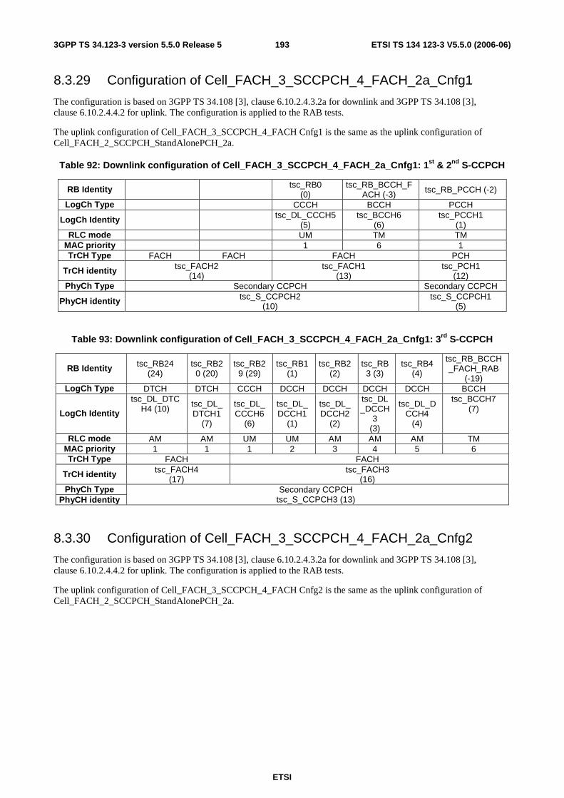
ETSI
ETSI TS 134 123-3 V5.5.0 (2006-06) 1933GPP TS 34.123-3 version 5.5.0 Release 5
8.3.29 Configuration of Cell_FACH_3_SCCPCH_4_FACH_2a_Cnfg1
The configuration is based on 3GPP TS 34.108 [3], clause 6.10.2.4.3.2a for downlink and 3GPP TS 34.108 [3], clause 6.10.2.4.4.2 for uplink. The configuration is applied to the RAB tests.
The uplink configuration of Cell_FACH_3_SCCPCH_4_FACH Cnfg1 is the same as the uplink configuration of Cell_FACH_2_SCCPCH_StandAlonePCH_2a.
Table 92: Downlink configuration of Cell_FACH_3_SCCPCH_4_FACH_2a_Cnfg1: 1st & 2nd S-CCPCH
RB Identity tsc_RB0 (0)
tsc_RB_BCCH_FACH (-3) tsc_RB_PCCH (-2)
LogCh Type CCCH BCCH PCCH
LogCh Identity tsc_DL_CCCH5 (5)
tsc_BCCH6 (6)
tsc_PCCH1 (1)
RLC mode UM TM TM MAC priority 1 6 1 TrCH Type FACH FACH FACH PCH
TrCH identity tsc_FACH2 (14)
tsc_FACH1 (13)
tsc_PCH1 (12)
PhyCh Type Secondary CCPCH Secondary CCPCH
PhyCH identity tsc_S_CCPCH2 (10)
tsc_S_CCPCH1 (5)
Table 93: Downlink configuration of Cell_FACH_3_SCCPCH_4_FACH_2a_Cnfg1: 3rd S-CCPCH
RB Identity tsc_RB24 (24)
tsc_RB20 (20)
tsc_RB29 (29)
tsc_RB1 (1)
tsc_RB2 (2)
tsc_RB3 (3)
tsc_RB4 (4)
tsc_RB_BCCH_FACH_RAB
(-19) LogCh Type DTCH DTCH CCCH DCCH DCCH DCCH DCCH BCCH
LogCh Identity
tsc_DL_DTCH4 (10)
tsc_DL_DTCH1
(7)
tsc_DL_CCCH6
(6)
tsc_DL_DCCH1
(1)
tsc_DL_DCCH2
(2)
tsc_DL_DCCH
3 (3)
tsc_DL_DCCH4
(4)
tsc_BCCH7 (7)
RLC mode AM AM UM UM AM AM AM TM MAC priority 1 1 1 2 3 4 5 6 TrCH Type FACH FACH
TrCH identity tsc_FACH4 (17)
tsc_FACH3 (16)
PhyCh Type PhyCH identity
Secondary CCPCH tsc_S_CCPCH3 (13)
8.3.30 Configuration of Cell_FACH_3_SCCPCH_4_FACH_2a_Cnfg2
The configuration is based on 3GPP TS 34.108 [3], clause 6.10.2.4.3.2a for downlink and 3GPP TS 34.108 [3], clause 6.10.2.4.4.2 for uplink. The configuration is applied to the RAB tests.
The uplink configuration of Cell_FACH_3_SCCPCH_4_FACH Cnfg2 is the same as the uplink configuration of Cell_FACH_2_SCCPCH_StandAlonePCH_2a.
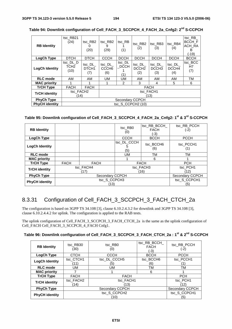
ETSI
ETSI TS 134 123-3 V5.5.0 (2006-06) 1943GPP TS 34.123-3 version 5.5.0 Release 5
Table 94: Downlink configuration of Cell_FACH_3_SCCPCH_4_FACH_2a_Cnfg2: 2nd S-CCPCH
RB Identity
tsc_RB21 (24) tsc_RB2
0 (20)
tsc_RB29
(29)
tsc_RB1
(1)
tsc_RB2 (2)
tsc_RB3 (3)
tsc_RB4 (4)
tsc_RB_BCCH_FACH_RA
B (-19)
LogCh Type DTCH DTCH CCCH DCCH DCCH DCCH DCCH BCCH
LogCh Identity
tsc_DL_DTCH2 (10)
tsc_DL_DTCH1
(7)
tsc_DL_CCCH6
(6)
tsc_DL_DCCH
1 (1)
tsc_DL_DCCH2
(2)
tsc_DL_DCCH3
(3)
tsc_DL_DCCH4
(4)
tsc_BCCH7 (7)
RLC mode AM AM UM UM AM AM AM TM MAC priority 1 1 1 2 3 4 5 6 TrCH Type FACH FACH FACH
TrCH identity tsc_FACH2 (14)
tsc_FACH1 (13)
PhyCh Type Secondary CCPCH PhyCH identity tsc_S_CCPCH2 (10)
Table 95: Downlink configuration of Cell_FACH_3_SCCPCH_4_FACH_2a_Cnfg2: 1st & 3rd S-CCPCH
RB Identity
tsc_RB0 (0)
tsc_RB_BCCH_FACH
(-3)
tsc_RB_PCCH (-2)
LogCh Type CCCH BCCH PCCH
LogCh Identity
tsc_DL_CCCH
5 (5)
tsc_BCCH6 (6)
tsc_PCCH1 (1)
RLC mode UM TM TM MAC priority 1 6 1 TrCH Type FACH FACH FACH PCH
TrCH identity tsc_FACH4 (17)
tsc_FACH3 (16)
tsc_PCH1 (12)
PhyCh Type Secondary CCPCH Secondary CCPCH
PhyCH identity tsc_S_CCPCH3 (13)
tsc_S_CCPCH1 (5)
8.3.31 Configuration of Cell_FACH_3_SCCPCH_3_FACH_CTCH_2a
The configuration is based on 3GPP TS 34.108 [3], clause 6.10.2.4.3.2 for downlink and 3GPP TS 34.108 [3], clause 6.10.2.4.4.2 for uplink. The configuration is applied to the RAB tests.
The uplink configuration of Cell_FACH_3_SCCPCH_3_FACH_CTCH_2a is the same as the uplink configuration of Cell_FACH Cell_FACH_3_SCCPCH_4_FACH Cnfg1.
Table 96: Downlink configuration of Cell_FACH_3_SCCPCH_3_FACH_CTCH_2a : 1st & 2nd S-CCPCH
RB Identity tsc_RB30 (30)
tsc_RB0 (0)
tsc_RB_BCCH_FACH
(-3)
tsc_RB_PCCH (-2)
LogCh Type CTCH CCCH BCCH PCCH
LogCh Identity tsc_CTCH1 (11)
tsc_DL_CCCH5 (5)
tsc_BCCH6 (6)
tsc_PCCH1 (1)
RLC mode UM UM TM TM MAC priority 7 1 6 1 TrCH Type FACH FACH PCH
TrCH identity tsc_FACH2 (14)
tsc_FACH1 (13)
tsc_PCH1 (12)
PhyCh Type Secondary CCPCH Secondary CCPCH
PhyCH identity tsc_S_CCPCH2 (10)
tsc_S_CCPCH1 (5)
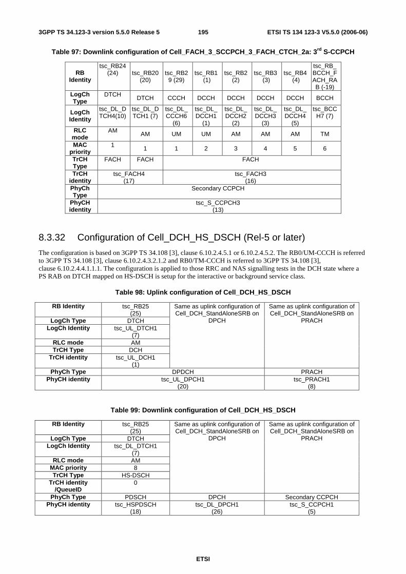
ETSI
ETSI TS 134 123-3 V5.5.0 (2006-06) 1953GPP TS 34.123-3 version 5.5.0 Release 5
Table 97: Downlink configuration of Cell_FACH_3_SCCPCH_3_FACH_CTCH_2a: 3rd S-CCPCH
RB Identity
tsc_RB24 (24) tsc_RB20
(20) tsc_RB2
9 (29) tsc_RB1
(1) tsc_RB2
(2) tsc_RB3
(3) tsc_RB4
(4)
tsc_RB_BCCH_FACH_RAB (-19)
LogCh Type
DTCH DTCH CCCH DCCH DCCH DCCH DCCH BCCH
LogCh Identity
tsc_DL_DTCH4(10)
tsc_DL_DTCH1 (7)
tsc_DL_CCCH6
(6)
tsc_DL_DCCH1
(1)
tsc_DL_DCCH2
(2)
tsc_DL_DCCH3
(3)
tsc_DL_DCCH4
(5)
tsc_BCCH7 (7)
RLC mode
AM AM UM UM AM AM AM TM
MAC priority
1 1 1 2 3 4 5 6
TrCH Type
FACH FACH FACH
TrCH identity
tsc_FACH4 (17)
tsc_FACH3 (16)
PhyCh Type
Secondary CCPCH
PhyCH identity
tsc_S_CCPCH3 (13)
8.3.32 Configuration of Cell_DCH_HS_DSCH (Rel-5 or later)
The configuration is based on 3GPP TS 34.108 [3], clause 6.10.2.4.5.1 or 6.10.2.4.5.2. The RB0/UM-CCCH is referred to 3GPP TS 34.108 [3], clause 6.10.2.4.3.2.1.2 and RB0/TM-CCCH is referred to 3GPP TS 34.108 [3], clause 6.10.2.4.4.1.1.1. The configuration is applied to those RRC and NAS signalling tests in the DCH state where a PS RAB on DTCH mapped on HS-DSCH is setup for the interactive or background service class.
Table 98: Uplink configuration of Cell_DCH_HS_DSCH
RB Identity tsc_RB25 (25)
LogCh Type DTCH LogCh Identity tsc_UL_DTCH1
(7) RLC mode AM TrCH Type DCH
TrCH identity tsc_UL_DCH1 (1)
Same as uplink configuration of Cell_DCH_StandAloneSRB on
DPCH
Same as uplink configuration of Cell_DCH_StandAloneSRB on
PRACH
PhyCh Type DPDCH PRACH PhyCH identity tsc_UL_DPCH1
(20) tsc_PRACH1
(8)
Table 99: Downlink configuration of Cell_DCH_HS_DSCH
RB Identity tsc_RB25 (25)
LogCh Type DTCH LogCh Identity tsc_DL_DTCH1
(7) RLC mode AM
MAC priority 8 TrCH Type HS-DSCH
TrCH identity /QueueID
0
Same as uplink configuration of Cell_DCH_StandAloneSRB on
DPCH
Same as uplink configuration of Cell_DCH_StandAloneSRB on
PRACH
PhyCh Type PDSCH DPCH Secondary CCPCH PhyCH identity tsc_HSPDSCH
(18) tsc_DL_DPCH1
(26) tsc_S_CCPCH1
(5)

ETSI
ETSI TS 134 123-3 V5.5.0 (2006-06) 1963GPP TS 34.123-3 version 5.5.0 Release 5
8.3.33 Configuration of cell_One_DTCH_HS_DSCH_MAC (Rel-5 or later)
The configuration is based on 3GPP TS 34.108 [3], clause 6.10.2.4.5.1. The RB0/UM-CCCH is referred to 3GPP TS 34.108 [3], clause 6.10.2.4.3.2.1.2 and RB0/TM-CCCH is referred to 3GPP TS 34.108 [3], clause 6.10.2.4.4.1.1.1. The configuration is applied to those MAC-HS Signalling tests in the DCH state where a PS RAB on DTCH mapped on HS-DSCH is setup for the interactive or background service class.
Table 100: Uplink configuration of cell_One_DTCH_HS_DSCH_MAC
RB Identity tsc_RB_MAC_HS (-25)
LogCh Type DTCH LogCh Identity tsc_UL_DTCH1
(7) RLC mode TM TrCH Type DCH
TrCH identity tsc_UL_DCH1 (1)
Same as uplink configuration of Cell_DCH_StandAloneSRB on
DPCH
Same as uplink configuration of Cell_DCH_StandAloneSRB on
PRACH
PhyCh Type DPDCH PRACH PhyCH identity tsc_UL_DPCH1
(20) tsc_PRACH1
(8)
Table 101: Downlink configuration of Cell_DCH_HS_DSCH
RB Identity tsc_RB_MAC_HS (-25)
LogCh Type DTCH LogCh Identity tsc_DL_DTCH1
(7) RLC mode TM
MAC priority 8 TrCH Type HS-DSCH
TrCH identity /QueueID
0
Same as downlink configuration of Cell_DCH_StandAloneSRB
on DPCH
Same as downlink configuration of Cell_DCH_StandAloneSRB
on sCCPCH
PhyCh Type PDSCH DPCH Secondary CCPCH PhyCH identity tsc_HSPDSCH
(18) tsc_DL_DPCH1
(26) tsc_S_CCPCH1
(5)
8.3.34 Configuration of Cell_ 2UM_3AM_DCH_HS_DSCH (Rel-5 or later)
The configuration is based on 3GPP TS 34.108[3], clause 6.11.4a The RB0/UM-CCCH is referred to 3GPP TS 34.108[3], clause 6.10.2.4.3.2.1.2 and RB0/TM-CCCH is referred to 3GPP TS 34.108 [3], clause 6.10.2.4.4.1.1.1. The configuration is applied to MAC test case 7.1.5.2.
Table102: Uplink configuration of Cell_2UM_3AM_DCH_HS_DSCH
RB Identity tsc_RB26 (26)
tsc_RB27 (27)
tsc_RB25 (25)
tsc_RB28 (28)
tsc_RB17 (17)
LogCh Type DTCH DTCH DTCH DTCH DTCH
LogCh Identity
tsc_UL_DTCH1
(7)
tsc_UL_DTCH2 (8)
tsc_UL_DTCH3 (9)
tsc_UL_DTCH4 (10)
tsc_UL_DTCH5 (13)
RLC mode UM UM AM AM AM TrCH Type DCH
TrCH identity tsc_UL_DCH1 (1)
Same as uplink
configuration of
Cell_DCH_StandAloneSRB on
DPCH
Same as uplink
configuration of
Cell_DCH_StandAloneSRB on PRACH
PhyCh Type DPDCH PRACH
PhyCH identity
tsc_UL_DPCH1 (20)
tsc_PRACH1 (8)

ETSI
ETSI TS 134 123-3 V5.5.0 (2006-06) 1973GPP TS 34.123-3 version 5.5.0 Release 5
Table 103: Downlink configuration of Cell_2UM_3AM_DCH_HS_DSCH
RB Identity tsc_RB26 (26)
tsc_RB27 (27)
tsc_RB25 (25)
tsc_RB28 (28)
tsc_RB17 ()
LogCh Type DTCH DTCH DTCH DTCH DTCH
LogCh Identity
tsc_DL_DTCH1
(7)
tsc_DL_DTCH2 (8)
tsc_DL_DTCH3 (9)
tsc_DL_DTCH4 (10)
tsc_DL_DTCH5 (11)
RLC mode UM UM AM AM AM MAC
priority 8 8 8 8 8
TrCH Type HS-DSCH TrCH
identity /QueueID
0 1 2
Same as downlink
configuration of
Cell_DCH_StandAlone
SRB on DPCH
Same as downlink
configuration of
Cell_DCH_StandAloneSRB on sCCPCH
PhyCh Type PDSCH DPCH Secondary
CCPCH
PhyCH identity
tsc_HSPDSCH (18)
tsc_DL_DPCH1 (26)
tsc_S_CCPCH1
(5)
8.3.35 Configuration of Cell_DCH_Speech_WAMR (Rel-5 or later)
The configuration is based on 3GPP TS 34.108 [3], clauses 6.10.2.4.1.62. The RB0/UM-CCCH is referred to 3GPP TS 34.108 [3], clause 6.10.2.4.3.2.1.2 and RB0/TM-CCCH is referred to 3GPP TS 34.108[3], clause 6.10.2.4.4.1.1.1. The configuration is applied to RAB test 14.2.62.
Table 104: Uplink configuration of Cell_DCH_Speech_WAMR
RB Identity
tsc_RB10 (10)
tsc_RB11 (11)
LogCh Type DTCH DTCH
LogCh Identity
tsc_UL_DTCH1 (7)
tsc_UL_DTCH2
(8) RLC
mode TM TM
TrCH Type DCH DCH
TrCH identity
tsc_UL_DCH1 (1)
tsc_UL_DCH2 (2)
Same as uplink configuration of
Cell_DCH_StandAloneSRB on DPCH
Same as uplink configuration of
Cell_DCH_StandAloneSRB on PRACH
PhyCh Type DPDCH PRACH
PhyCH identity
tsc_UL_DPCH1 (20)
tsc_PRACH1 (8)
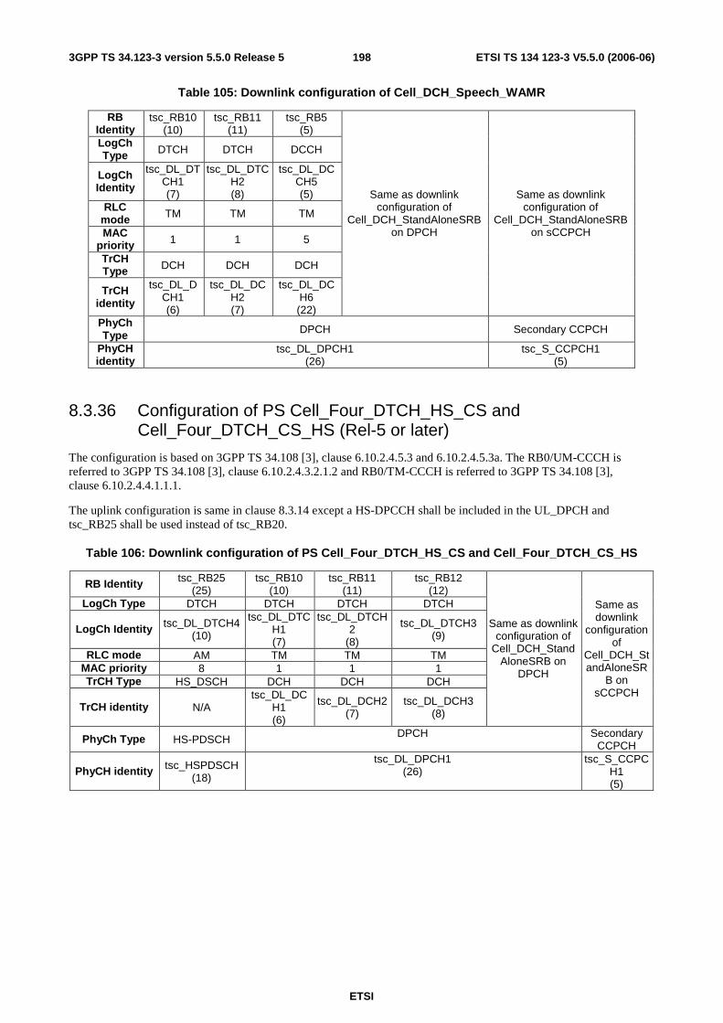
ETSI
ETSI TS 134 123-3 V5.5.0 (2006-06) 1983GPP TS 34.123-3 version 5.5.0 Release 5
Table 105: Downlink configuration of Cell_DCH_Speech_WAMR
RB Identity
tsc_RB10 (10)
tsc_RB11 (11)
tsc_RB5 (5)
LogCh Type DTCH DTCH DCCH
LogCh Identity
tsc_DL_DTCH1 (7)
tsc_DL_DTCH2 (8)
tsc_DL_DCCH5 (5)
RLC mode TM TM TM
MAC priority 1 1 5
TrCH Type DCH DCH DCH
TrCH identity
tsc_DL_DCH1 (6)
tsc_DL_DCH2 (7)
tsc_DL_DCH6 (22)
Same as downlink configuration of
Cell_DCH_StandAloneSRB on DPCH
Same as downlink configuration of
Cell_DCH_StandAloneSRB on sCCPCH
PhyCh Type DPCH Secondary CCPCH
PhyCH identity
tsc_DL_DPCH1 (26)
tsc_S_CCPCH1 (5)
8.3.36 Configuration of PS Cell_Four_DTCH_HS_CS and Cell_Four_DTCH_CS_HS (Rel-5 or later)
The configuration is based on 3GPP TS 34.108 [3], clause 6.10.2.4.5.3 and 6.10.2.4.5.3a. The RB0/UM-CCCH is referred to 3GPP TS 34.108 [3], clause 6.10.2.4.3.2.1.2 and RB0/TM-CCCH is referred to 3GPP TS 34.108 [3], clause 6.10.2.4.4.1.1.1.
The uplink configuration is same in clause 8.3.14 except a HS-DPCCH shall be included in the UL_DPCH and tsc_RB25 shall be used instead of tsc_RB20.
Table 106: Downlink configuration of PS Cell_Four_DTCH_HS_CS and Cell_Four_DTCH_CS_HS
RB Identity tsc_RB25 (25)
tsc_RB10 (10)
tsc_RB11 (11)
tsc_RB12 (12)
LogCh Type DTCH DTCH DTCH DTCH
LogCh Identity tsc_DL_DTCH4 (10)
tsc_DL_DTCH1 (7)
tsc_DL_DTCH2
(8)
tsc_DL_DTCH3 (9)
RLC mode AM TM TM TM MAC priority 8 1 1 1 TrCH Type HS_DSCH DCH DCH DCH
TrCH identity N/A tsc_DL_DC
H1 (6)
tsc_DL_DCH2 (7)
tsc_DL_DCH3 (8)
Same as downlink configuration of
Cell_DCH_StandAloneSRB on
DPCH
Same as downlink
configuration of
Cell_DCH_StandAloneSR
B on sCCPCH
PhyCh Type HS-PDSCH DPCH Secondary CCPCH
PhyCH identity tsc_HSPDSCH (18)
tsc_DL_DPCH1 (26)
tsc_S_CCPCH1 (5)
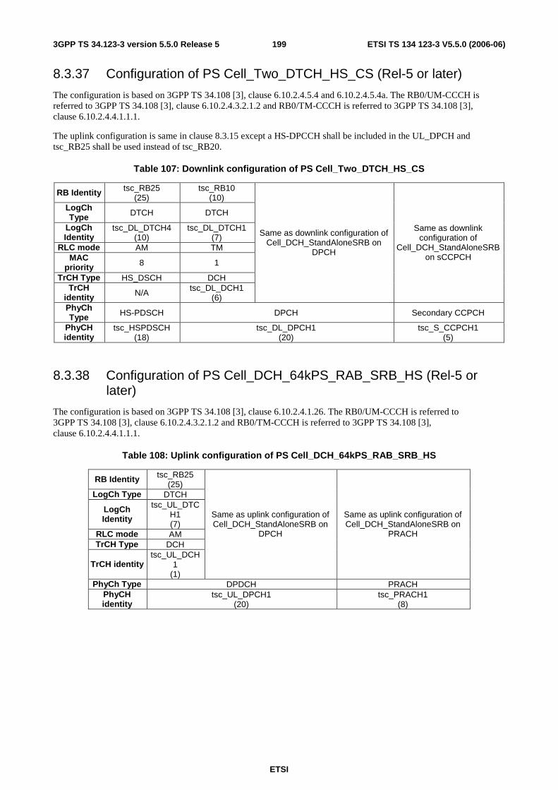
ETSI
ETSI TS 134 123-3 V5.5.0 (2006-06) 1993GPP TS 34.123-3 version 5.5.0 Release 5
8.3.37 Configuration of PS Cell_Two_DTCH_HS_CS (Rel-5 or later)
The configuration is based on 3GPP TS 34.108 [3], clause 6.10.2.4.5.4 and 6.10.2.4.5.4a. The RB0/UM-CCCH is referred to 3GPP TS 34.108 [3], clause 6.10.2.4.3.2.1.2 and RB0/TM-CCCH is referred to 3GPP TS 34.108 [3], clause 6.10.2.4.4.1.1.1.
The uplink configuration is same in clause 8.3.15 except a HS-DPCCH shall be included in the UL_DPCH and tsc_RB25 shall be used instead of tsc_RB20.
Table 107: Downlink configuration of PS Cell_Two_DTCH_HS_CS
RB Identity tsc_RB25 (25)
tsc_RB10 (10)
LogCh Type DTCH DTCH
LogCh Identity
tsc_DL_DTCH4 (10)
tsc_DL_DTCH1 (7)
RLC mode AM TM MAC
priority 8 1
TrCH Type HS_DSCH DCH TrCH
identity N/A tsc_DL_DCH1 (6)
Same as downlink configuration of Cell_DCH_StandAloneSRB on
DPCH
Same as downlink configuration of
Cell_DCH_StandAloneSRB on sCCPCH
PhyCh Type HS-PDSCH DPCH Secondary CCPCH
PhyCH identity
tsc_HSPDSCH (18)
tsc_DL_DPCH1 (20)
tsc_S_CCPCH1 (5)
8.3.38 Configuration of PS Cell_DCH_64kPS_RAB_SRB_HS (Rel-5 or later)
The configuration is based on 3GPP TS 34.108 [3], clause 6.10.2.4.1.26. The RB0/UM-CCCH is referred to 3GPP TS 34.108 [3], clause 6.10.2.4.3.2.1.2 and RB0/TM-CCCH is referred to 3GPP TS 34.108 [3], clause 6.10.2.4.4.1.1.1.
Table 108: Uplink configuration of PS Cell_DCH_64kPS_RAB_SRB_HS
RB Identity tsc_RB25 (25)
LogCh Type DTCH
LogCh Identity
tsc_UL_DTCH1 (7)
RLC mode AM TrCH Type DCH
TrCH identity tsc_UL_DCH
1 (1)
Same as uplink configuration of Cell_DCH_StandAloneSRB on
DPCH
Same as uplink configuration of Cell_DCH_StandAloneSRB on
PRACH
PhyCh Type DPDCH PRACH PhyCH identity
tsc_UL_DPCH1 (20)
tsc_PRACH1 (8)

ETSI
ETSI TS 134 123-3 V5.5.0 (2006-06) 2003GPP TS 34.123-3 version 5.5.0 Release 5
Table 109: Downlink configuration of PS Cell_DCH_64kPS_RAB_SRB SRB
RB Identity tsc_RB25 (25)
LogCh Type DTCH
LogCh Identity
tsc_DL_DTCH1 (7)
RLC mode AM MAC
priority 8
TrCH Type DCH
TrCH identity
tsc_DL_DCH1
(6)
Same as downlink configuration of Cell_DCH_StandAloneSRB on
DPCH
Same as downlink configuration of Cell_DCH_StandAloneSRB on
sCCPCH
PhyCh Type DPCH Secondary CCPCH
PhyCH identity
tsc_DL_DPCH1 (26)
tsc_S_CCPCH1 (5)
8.3.39 Configuration of PS Cell_DCH_2AM_HS_DSCH (Rel-5 or later)
The configuration is based on 3GPP TS 34.108 [3], clauses 6.10.2.4.1.26 and 6.10.2.4.1.57. The RB0/UM-CCCH is referred to 3GPP TS 34.108 [3], clause 6.10.2.4.3.2.1.2 with 2 AM RAB and RB0/TM-CCCH is referred to 3GPP TS 34.108 [3], clause 6.10.2.4.4.1.1.1. The configuration is applied to MAC and RAB test cases.
Table 110: Uplink configuration of Cell_DCH_2AM_HS_DSCH
RB Identity tsc_RB25 (25)
tsc_RB17 (17)
LogCh Type DTCH DTCH LogCh Identity
tsc_UL_DTCH1 (7)
tsc_UL_DTCH2 (8)
RLC mode AM AM TrCH Type DCH DCH
TrCH identity tsc_UL_DCH1 (1)
tsc_UL_DCH2 (2)
Same as uplink configuration of
Cell_DCH_StandAloneSRB on DPCH
Same as uplink configuration of
Cell_DCH_StandAloneSRB on PRACH
PhyCh Type DPDCH PRACH PhyCH identity
tsc_UL_DPCH1 (20)
tsc_PRACH1 (8)
Table 111: Downlink configuration of Cell_DCH_2AM_HS_DSCH
RB Identity tsc_RB25 (25)
tsc_RB17 (17)
LogCh Type DTCH DTCH LogCh Identity tsc_DL_DTCH1
(7) tsc_DL_DTCH2
(8) RLC mode AM AM
MAC priority 8 8 TrCH Type HS-DSCH HS-DSCH
TrCH identity /QueueID
0 1
Same as uplink configuration of
Cell_DCH_StandAloneSRB on DPCH
Same as uplink configuration of
Cell_DCH_StandAloneSRB on PRACH
PhyCh Type PDSCH
DPCH Secondary CCPCH
PhyCH identity
tsc_HSPDSCH (18)
tsc_DL_DPCH1 (26)
tsc_S_CCPCH1 (5)
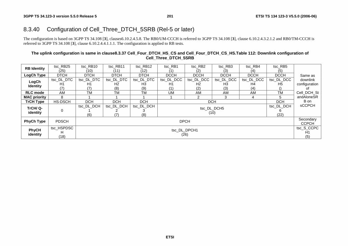
ETSI
ETSI TS 134 123-3 V5.5.0 (2006-06) 2013GPP TS 34.123-3 version 5.5.0 Release 5
8.3.40 Configuration of Cell_Three_DTCH_5SRB (Rel-5 or later)
The configuration is based on 3GPP TS 34.108 [3], clauses6.10.2.4.5.8. The RB0/UM-CCCH is referred to 3GPP TS 34.108 [3], clause 6.10.2.4.3.2.1.2 and RB0/TM-CCCH is referred to 3GPP TS 34.108 [3], clause 6.10.2.4.4.1.1.1. The configuration is applied to RB tests.
The uplink configuration is same in clause8.3.37 Cell_Four_DTCH_HS_CS and Cell_Four_DTCH_CS_HS.Table 112: Downlink configuration of Cell_Three_DTCH_5SRB
RB Identity tsc_RB25 (25)
tsc_RB10 (10)
tsc_RB11 (11)
tsc_RB12 (12)
tsc_RB1 (1)
tsc_RB2 (2)
tsc_RB3 (3)
tsc_RB4 (4)
tsc_RB5 (5)
LogCh Type DTCH DTCH DTCH DTCH DCCH DCCH DCCH DCCH DCCH
LogCh Identity
tsc_DL_DTCH1 (7)
tsc_DL_DTCH1 (7)
tsc_DL_DTCH2 (8)
tsc_DL_DTCH3 (9)
tsc_DL_DCCH1 (1)
tsc_DL_DCCH2 (2)
tsc_DL_DCCH3 (3)
tsc_DL_DCCH4 (4)
tsc_DL_DCCH5 ()
RLC mode AM TM TM TM UM AM AM AM TM MAC priority 8 1 1 1 1 2 3 4 5 TrCH Type HS-DSCH DCH DCH DCH DCH DCH
TrCH/ Q- identity 0
tsc_DL_DCH1
(6)
tsc_DL_DCH2
(7)
tsc_DL_DCH3
(8)
tsc_DL_DCH5 (10)
tsc_DL_DCH6
(22)
Same as downlink
configuration of
Cell_DCH_StandAloneSR
B on sCCPCH
PhyCh Type PDSCH DPCH Secondary CCPCH
PhyCH identity
tsc_HSPDSCH
(18)
tsc_DL_DPCH1 (26)
tsc_S_CCPCH1 (5)

ETSI
ETSI TS 134 123-3 V5.5.0 (2006-06) 2023GPP TS 34.123-3 version 5.5.0 Release 5
8.3.41 Configuration of Cell_Five_DTCH_CS_HS (Rel-5 or later)
The configuration is based on 3GPP TS 34.108 [3], clauses 6.10.2.4.1.62. The RB0/UM-CCCH is referred to 3GPP TS 34.108 [3], clause 6.10.2.4.3.2.1.2 and RB0/TM-CCCH is referred to 3GPP TS 34.108 [3], clause 6.10.2.4.4.1.1.1. The configuration is applied to RB tests.
The uplink configuration is same in clause 8.3.3 Cell_DCH_Speech .
Table 113: Downlink configuration of Cell_Three_DTCH_5SRB
RB Identity
tsc_RB10 (10)
tsc_RB11 (11)
tsc_RB12 (12)
tsc_RB1 (1)
tsc_RB2 (2)
tsc_RB3 (3)
tsc_RB4 (4)
tsc_RB5 (5)
LogCh Type DTCH DTCH DTCH DCCH DCCH DCCH DCCH DCCH
LogCh Identity
tsc_DL_DTCH1 (7)
tsc_DL_DTCH2 (8)
tsc_DL_DTCH3
(9)
tsc_DL_DCCH1 (1)
tsc_DL_DCCH2
(2)
tsc_DL_DCCH3
(3)
tsc_DL_DCCH4
(4)
tsc_DL_DCCH5
() RLC
mode TM TM TM UM AM AM AM TM
MAC priority 1 1 1 1 2 3 4 5
TrCH Type DCH DCH DCH DCH DCH
TrCH identity
tsc_DL_DCH1 (6)
tsc_DL_DCH2 (7)
tsc_DL_DCH3 (8)
tsc_DL_DCH5 (10)
tsc_DL_DCH6 (22)
Same as downlink
configuration of Cell_DCH_Stand
AloneSRB on sCCPCH
PhyCh Type
DPCH
Secondary CCPCH
PhyCH identity
tsc_DL_DPCH1 (26)
tsc_S_CCPCH1 (5)
8.3.41 Configuration of Cell_Five_DTCH_CS_HS (Rel-5 or later)
The configuration is based on 3GPP TS 34.108 [3], clauses 6.10.2.4.5.7. The RB0/UM-CCCH is referred to 3GPP TS 34.108 [3], clause 6.10.2.4.3.2.1.2 and RB0/TM-CCCH is referred to 3GPP TS 34.108 [3], clause 6.10.2.4.4.1.1.1. The configuration is applied to RB tests.
Table 114: Uplink configuration of Cell_Five_DTCH_CS_HS and Cell_Five_DTCH_CS_HS
RB Identity
tsc_RB10 (10)
tsc_RB11 (11)
tsc_RB12 (12)
tsc_RB25 (25)
tsc_RB17 (17)
LogCh Type DTCH DTCH DTCH DTCH DTCH
LogCh Identity
tsc_UL_DTCH1
(7)
tsc_UL_DTCH2
(8)
tsc_UL_DTCH3
(9)
tsc_UL_DTCH4 (10)
tsc_UL_DTCH5 (13)
RLC mode TM TM TM AM AM
MAC priority 1 1 1 1 1
TrCH Type DCH DCH DCH DCH DCH
TrCH identity
tsc_UL_DCH1 (1)
tsc_UL_DCH2 (2)
tsc_UL_DCH3 (3)
tsc_UL_DCH4 (4)
tsc_UL_DCH5 (5)
Same as uplink configuration of Cell_DCH_StandAloneSRB on DPCH except
TrCH Identity is tsc_UL_DCH6
(21)
Same as uplink configuration of Cell_DCH_StandAloneSRB on
PRACH
PhyCh Type DPDCH Secondary
CCPCH PhyCH identity
tsc_UL_DPCH1 (20)
tsc_S_CCPCH1 (5)
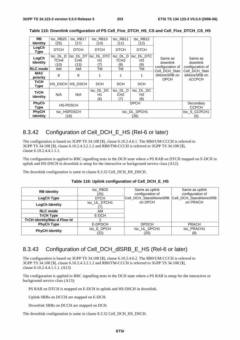
ETSI
ETSI TS 134 123-3 V5.5.0 (2006-06) 2033GPP TS 34.123-3 version 5.5.0 Release 5
Table 115: Downlink configuration of PS Cell_Five_DTCH_HS_CS and Cell_Five_DTCH_CS_HS
RB Identity
tsc_RB25 (25)
tsc_RB17 (17)
tsc_RB10 (10)
tsc_RB11 (11)
tsc_RB12 (12)
LogCh Type DTCH DTCH DTCH DTCH DTCH
LogCh Identity
tsc_DL_DTCH4 (10)
tsc_DL_DTCH5 (13)
tsc_DL_DTCH1 (7)
tsc_DL_DTCH2
(8)
tsc_DL_DTCH3 (9)
RLC mode AM AM TM TM TM MAC
priority 8 8 1 1 1
TrCH Type HS_DSCH HS_DSCH DCH DCH DCH
TrCH identity N/A N/A
tsc_DL_DCH1 (6)
tsc_DL_DCH2 (7)
tsc_DL_DCH3 (8)
Same as downlink
configuration of Cell_DCH_StandAloneSRB on
DPCH
Same as downlink
configuration of Cell_DCH_StandAloneSRB on
sCCPCH
PhyCh Type HS-PDSCH DPCH Secondary
CCPCH PhyCH identity
tsc_HSPDSCH (18)
tsc_DL_DPCH1 (26)
tsc_S_CCPCH1 (5)
8.3.42 Configuration of Cell_DCH_E_HS (Rel-6 or later)
The configuration is based on 3GPP TS 34.108 [3], clause 6.10.2.4.6.1. The RB0/UM-CCCH is referred to 3GPP TS 34.108 [3], clause 6.10.2.4.3.2.1.2 and RB0/TM-CCCH is referred to 3GPP TS 34.108 [3], clause 6.10.2.4.4.1.1.1.
The configuration is applied to RRC signalling tests in the DCH state where a PS RAB on DTCH mapped on E-DCH in uplink and HS-DSCH in downlink is setup for the interactive or background service class (A12).
The downlink configuration is same in clause 8.3.32 Cell_DCH_HS_DSCH.
Table 116: Uplink configuration of Cell_DCH_E_HS
RB Identity tsc_RB25 (25)
LogCh Type DTCH
LogCh Identity tsc_UL_DTCH1 (7)
RLC mode AM TrCH Type E-DCH
TrCH identity/Mac-d Flow Id 2
Same as uplink configuration of
Cell_DCH_StandAloneSRB on DPCH
Same as uplink configuration of
Cell_DCH_StandAloneSRB on PRACH
PhyCh Type E-DPDCH DPDCH PRACH
PhyCH identity tsc_E_DPCH (22)
tsc_UL_DPCH1 (20)
tsc_PRACH1 (8)
8.3.43 Configuration of Cell_DCH_dlSRB_E_HS (Rel-6 or later)
The configuration is based on 3GPP TS 34.108 [3], clause 6.10.2.4.6.2. The RB0/UM-CCCH is referred to 3GPP TS 34.108 [3], clause 6.10.2.4.3.2.1.2 and RB0/TM-CCCH is referred to 3GPP TS 34.108 [3], clause 6.10.2.4.4.1.1.1. (A13)
The configuration is applied to RRC signalling tests in the DCH state where a PS RAB is setup for the interactive or background service class (A13):
PS RAB on DTCH is mapped on E-DCH in uplink and HS-DSCH in downlink.
Uplink SRBs on DCCH are mapped on E-DCH.
Downlink SRBs on DCCH are mapped on DCH.
The downlink configuration is same in clause 8.3.32 Cell_DCH_HS_DSCH.

ETSI
ETSI TS 134 123-3 V5.5.0 (2006-06) 2043GPP TS 34.123-3 version 5.5.0 Release 5
Table 117: Uplink configuration of Cell_DCH_dlSRB_E_HS
RB Identity tsc_RB25 (25)
LogCh Type DTCH
LogCh Identity tsc_UL_DTCH1 (7)
RLC mode AM
Same as uplink configuration of
Cell_DCH_StandAloneSRB on DPCH
TrCH Type E-DCH TrCH identity/ Mac-
d Flow Id 2 1
Same as uplink configuration of Cell_DCH_StandAloneSRB on
PRACH
PhyCh Type E-DPDCH PRACH
PhyCH identity tsc_E_DPCH (22)
tsc_PRACH1 (8)
8.3.44 Configuration of Cell_E_HS (Rel-6 or later)
The configuration is based on 3GPP TS 34.108 [3], clause 6.10.2.4.6.3. The RB0/UM-CCCH is referred to 3GPP TS 34.108 [3], clause 6.10.2.4.3.2.1.2 and RB0/TM-CCCH is referred to 3GPP TS 34.108 [3], clause 6.10.2.4.4.1.1.1.
The configuration is applied to RRC signalling tests in the DCH state where a PS RAB is setup for the interactive or background service class (A14):
PS RAB on DTCH is mapped on E-DCH in uplink and HS-DSCH in downlink.
Uplink SRBs on DCCH are mapped on E-DCH
Downlink SRBs on DCCH are mapped on HS-DSCH
The uplink configuration is same in clause 8.3.43 Cell_DCH_dlSRB_E_HS. In the downlink F-DPCH is configured.
Table 118: Downlink configuration of Cell_E_HS
RB Identity tsc_RB25 (25)
LogCh Type DTCH
LogCh Identity tsc_DL_DTCH1 (7)
RLC mode AM MAC priority 8
Same as downlink configuration of
Cell_DCH_StandAloneSRB on DPCH
TrCH Type HS-DSCH TrCH identity / Mac-
d Flow Id 0 1
Same as downlink configuration of Cell_DCH_StandAloneSRB
on PRACH
PhyCh Type PDSCH
Secondary CCPCH
PhyCH identity tsc_HSPDSCH (18)
tsc_S_CCPCH1 (5)
8.3.45 Configuration of PS Cell_Four_DTCH_E_HS_CS and Cell_Four_DTCH_CS_E_HS (Rel-6 or later)
The configuration is based on 3GPP TS 34.108 [3], clause 6.10.2.4.6.4. The RB0/UM-CCCH is referred to 3GPP TS 34.108 [3], clause 6.10.2.4.3.2.1.2 and RB0/TM-CCCH is referred to 3GPP TS 34.108 [3], clause 6.10.2.4.4.1.1.1.
The configuration is applied to RRC signalling tests in the DCH state where a PS RAB is setup for the interactive or background service class:
PS RAB on DTCH is mapped on E-DCH in uplink and HS-DSCH in downlink
CS RAB on DTCH are mapped on DCH in uplink and downlink

ETSI
ETSI TS 134 123-3 V5.5.0 (2006-06) 2053GPP TS 34.123-3 version 5.5.0 Release 5
Uplink SRBs on DCCH are mapped on E-DCH
Downlink SRBs on DCCH are mapped on HS-DSCH
The downlink configuration is same as in clause 8.3.36 Cell_Four_DTCH_HS_CS and Cell_Four_DTCH_CS_HS.
Table 119: Uplink configuration of Cell_Four_DTCH_E_HS_CS and Cell_Four_DTCH_CS_E_HS
RB Identity tsc_RB25 (25)
tsc_RB10 (10)
tsc_RB11 (11)
tsc_RB12 (12)
LogCh Type DTCH DTCH DTCH DTCH
LogCh Identity tsc_UL_DTC
H1 (7)
tsc_UL_DTCH1
(7)
tsc_UL_DTCH2
(8)
tsc_UL_DTCH3
(9) RLC mode AM TM TM TM
MAC priority 1 1 1 TrCH Type E-DCH DCH DCH DCH
TrCH identity / Mac-d Flow Id
2 tsc_UL_DCH1 (1)
tsc_UL_DCH2 (2)
tsc_UL_DCH3 (3)
Same as uplink configuration of
Cell_DCH_StandAloneSRB on DPCH
Same as uplink configuration of
Cell_DCH_StandAloneSRB on PRACH
PhyCh Type E-DPDCH DPDCH PRACH
PhyCH identity tsc_E_DPCH (22)
tsc_UL_DPCH1 (20)
tsc_PRACH1 (8)
8.3.46 Configuration of Cell_2DCH_2AM_dlSRB_E_HS (Rel-6 or later)
The configuration is based on 3GPP TS 34.108 [3], clause 6.10.2.4.6.2. The RB0/UM-CCCH is referred to 3GPP TS 34.108 [3], clause 6.10.2.4.3.2.1.2 and RB0/TM-CCCH is referred to 3GPP TS 34.108 [3], clause 6.10.2.4.4.1.1.1. (A13)
The configuration is applied to RRC signalling tests in the DCH state where a PS RAB is setup for the interactive or background service class (A15):
2 AM PS RAB on DTCH is mapped on E-DCH in uplink and HS-DSCH in downlink.
Uplink SRBs on DCCH are mapped on E-DCH.
Downlink SRBs on DCCH are mapped on DCH.
The downlink configuration is same in clause 8.3.39 Cell_2DCH_ 2AM_HS_DSCH
Table 120: Uplink configuration of Cell_2DCH_2AM_dlSRB_E_HS
RB Identity tsc_RB25 (25)
tsc_RB17 (17)
LogCh Type DTCH DTCH LogCh Identity
tsc_UL_DTCH1 (7)
tsc_UL_DTCH2 (8)
RLC mode AM AM
Same as uplink configuration of
Cell_DCH_StandAloneSRB on DPCH
TrCH Type E-DCH TrCH
identity//Mac-d Flow Id
2 3 1
Same as uplink configuration of
Cell_DCH_StandAloneSRB on PRACH
PhyCh Type E-DPDCH PRACH PhyCH identity
tsc_E_DPCH (22)
tsc_PRACH1 (8)

ETSI
ETSI TS 134 123-3 V5.5.0 (2006-06) 2063GPP TS 34.123-3 version 5.5.0 Release 5
8.4 System information blocks scheduling All SIBs specified in 3GPP TS 34.108 [3] are broadcast for all test cases in the present document. The repeat period of broadcasting of a complete SIB configuration is 64 frames (0,64 s) as the default configuration.
Except MIB and SB1, they have the highest scheduling rates, SIB 7 has also a higher scheduling rate.
According to the default SIB contents in 3GPP TS 34.108 [3], SIB 11 and SIB12 have 3 segments. SIB 5 has 4 segments for FDD and 5 segments for 1.28 Mcps TDD. SIB 6 has 4 segments. MIB, SB1, SIB1, SIB 2, SIB 3, SIB 4, SIB 7 and SIB18 are not segmented, i.e. one segment for each. For the PDCP tests, SIB16 has 7 segments.
Use CMAC_SYSINFO_CONFIG_REQ, CMAC_SYSINFO_CONFIG_CNF and RLC_TR_DATA_REQ as interface to SS for broadcasting.
Two TSOs are defined, one for PER encoding function, the other for segmentation function. The TSOs shall be implemented in the tester.
8.4.1 Grouping SIBs for testing
Table 121
Used in Idle Mode MIB, SB1, (SB2), SIB1, SIB2, SIB3, SIB5, SIB7, SIB11 Mandatory in 3GPP TS 34.108 [3] Used in Connected Mode SIB4, SIB6, SIB12
Mandatory for FDD CPCH SIB8, SIB9 Mandatory for FDD DRAC SIB10
Mandatory for TDD SIB14 (for 3.84 Mcps TDD), SIB17 Mandatory for LCS SIB15, SIB15.1, SIB15.2, SIB15.3
Mandatory for ANSI-41 system SIB13, SIB13.1, SIB13.2, SIB13.3, SIB13.4 Mandatory for InterSys HO GERAN to UTRAN SIB16
Mandatory for Cell reselection SIB18
8.4.2 SIB configurations
Currently the ATS contains three SIB configurations, Configuration 1 is default for UTRAN/FDD SYSTEM, UTRAN/TDD, UTRAN/FDD + GERAN SYSTEM (not involving inter-RAT handover) and Inter-RAT UTRAN to GERAN. Configuration 2 is for test cases which need two S_CCPCH or two PRACH. Configuration 3 is for inter-RAT GERAN to UTRAN handover test cases.
Table 122
Configuration 1 MIB, SB1, SIB1, SIB2, SIB3, SIB4, SIB5, SIB6, SIB7, SIB11, SIB12, SIB18 Configuration 2 MIB, SB1, SIB1, SIB2, SIB3, SIB4, SIB5, SIB7, SIB11, SIB12, SIB18 Configuration 3 MIB, SB1, SIB1, SIB2, SIB3, SIB4, SIB5, SIB7, SIB11, SIB16, SIB18
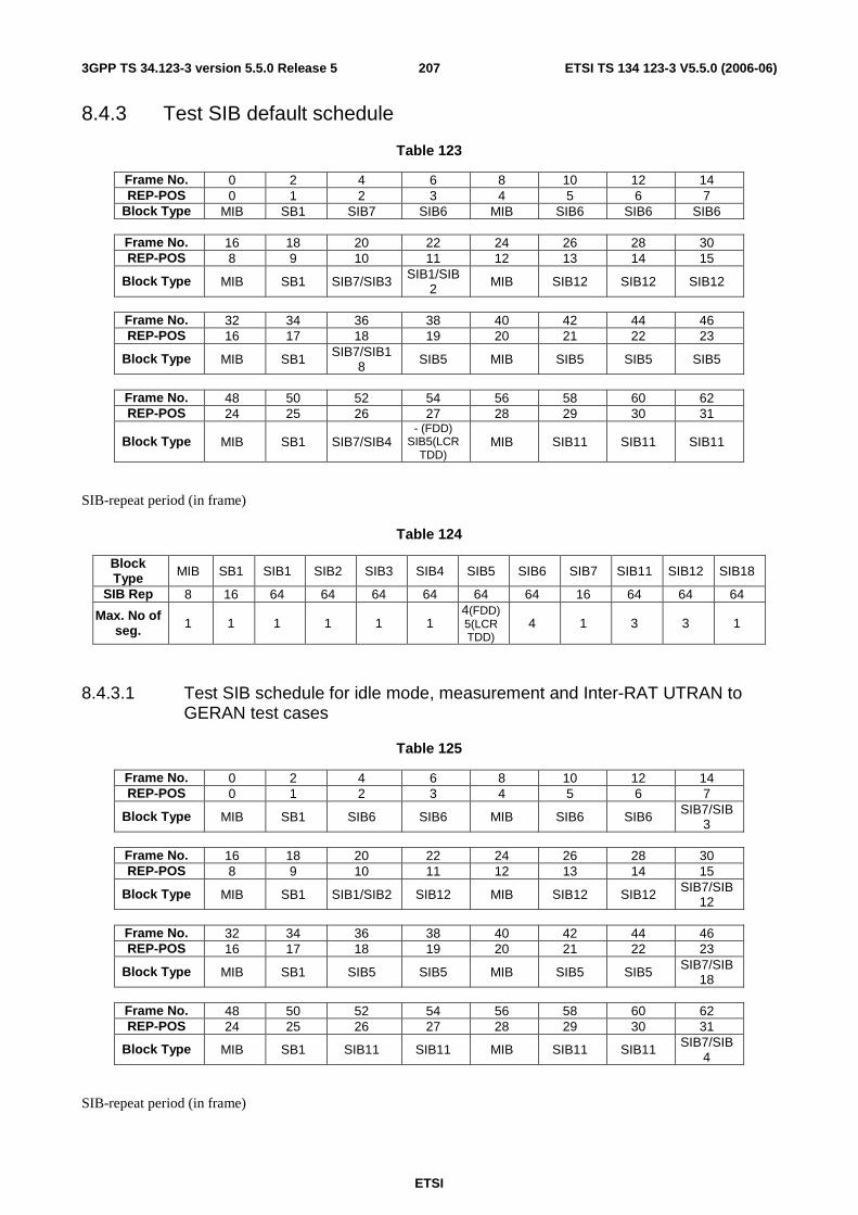
ETSI
ETSI TS 134 123-3 V5.5.0 (2006-06) 2073GPP TS 34.123-3 version 5.5.0 Release 5
8.4.3 Test SIB default schedule
Table 123
Frame No. 0 2 4 6 8 10 12 14 REP-POS 0 1 2 3 4 5 6 7
Block Type MIB SB1 SIB7 SIB6 MIB SIB6 SIB6 SIB6
Frame No. 16 18 20 22 24 26 28 30 REP-POS 8 9 10 11 12 13 14 15
Block Type MIB SB1 SIB7/SIB3 SIB1/SIB2 MIB SIB12 SIB12 SIB12
Frame No. 32 34 36 38 40 42 44 46 REP-POS 16 17 18 19 20 21 22 23
Block Type MIB SB1 SIB7/SIB18 SIB5 MIB SIB5 SIB5 SIB5
Frame No. 48 50 52 54 56 58 60 62 REP-POS 24 25 26 27 28 29 30 31
Block Type MIB SB1 SIB7/SIB4 - (FDD)
SIB5(LCR TDD)
MIB SIB11 SIB11 SIB11
SIB-repeat period (in frame)
Table 124
Block Type MIB SB1 SIB1 SIB2 SIB3 SIB4 SIB5 SIB6 SIB7 SIB11 SIB12 SIB18
SIB Rep 8 16 64 64 64 64 64 64 16 64 64 64
Max. No of seg. 1 1 1 1 1 1
4(FDD) 5(LCR TDD)
4 1 3 3 1
8.4.3.1 Test SIB schedule for idle mode, measurement and Inter-RAT UTRAN to GERAN test cases
Table 125
Frame No. 0 2 4 6 8 10 12 14 REP-POS 0 1 2 3 4 5 6 7
Block Type MIB SB1 SIB6 SIB6 MIB SIB6 SIB6 SIB7/SIB3
Frame No. 16 18 20 22 24 26 28 30 REP-POS 8 9 10 11 12 13 14 15
Block Type MIB SB1 SIB1/SIB2 SIB12 MIB SIB12 SIB12 SIB7/SIB12
Frame No. 32 34 36 38 40 42 44 46 REP-POS 16 17 18 19 20 21 22 23
Block Type MIB SB1 SIB5 SIB5 MIB SIB5 SIB5 SIB7/SIB18
Frame No. 48 50 52 54 56 58 60 62 REP-POS 24 25 26 27 28 29 30 31
Block Type MIB SB1 SIB11 SIB11 MIB SIB11 SIB11 SIB7/SIB4
SIB-repeat period (in frame)

ETSI
ETSI TS 134 123-3 V5.5.0 (2006-06) 2083GPP TS 34.123-3 version 5.5.0 Release 5
Table 126
Block Type MIB SB1 SIB1 SIB2 SIB3 SIB4 SIB5 SIB6 SIB7 SIB11 SIB12 SIB18
SIB Rep 8 16 64 64 64 64 64 64 16 64 64 64
Max. No of seg. 1 1 1 1 1 1
4(FDD) 5(LCR TDD)
4(FDD) 3(LCR TDD)
1 4 4 1
8.4.4 Test SIB special schedule
8.4.4.1 Test SIB schedule for two S-CCPCH or two PRACH
Table 127
Frame No. 0 2 4 6 8 10 12 14 REP-POS 0 1 2 3 4 5 6 7
Block Type MIB SB1 SB1 MIB SIB1 SIB18 SIB2
Frame No. 16 18 20 22 24 26 28 30 REP-POS 8 9 10 11 12 13 14 15
Block Type MIB SB1 SB1 SIB7 MIB SIB3 SIB4
Frame No. 32 34 36 38 40 42 44 46 REP-POS 16 17 18 19 20 21 22 23
Block Type MIB SB1 SB1 SIB5 MIB SIB5 SIB5 SIB5
Frame No. 48 50 52 54 56 58 60 62 REP-POS 24 25 26 27 28 29 30 31
Block Type MIB SB1 SB1 SIB7 MIB SIB11 SIB11 SIB11
Frame No. 64 66 68 70 72 74 76 78 REP-POS 32 33 34 35 36 37 38 39
Block Type MIB SB1 SB1 SIB5 MIB SIB5 SIB5 SIB5
Frame No. 80 82 84 86 88 90 92 94 REP-POS 40 41 42 43 44 45 46 47
Block Type MIB SB1 SB1 SIB7 MIB SIB3 SIB4
Frame No. 96 98 100 102 104 106 108 110 REP-POS 48 49 50 51 52 53 54 55
Block Type MIB SB1 SB1 MIB
Frame No. 112 114 116 118 120 122 124 126 REP-POS 56 57 58 59 60 61 62 63
Block Type MIB SB1 SB1 SIB7 MIB SIB12 SIB12 SIB12
SIB-repeat period (in frame)
Table 128
Block Type MIB SB1 SIB1 SIB2 SIB3 SIB4 SIB5 SIB7 SIB11 SIB12 SIB18
SIB Rep 8 16 128 128 64 64 128 32 128 128 128 Max. No of
seg. 1 2 1 1 1 1 8 1 3 3 1
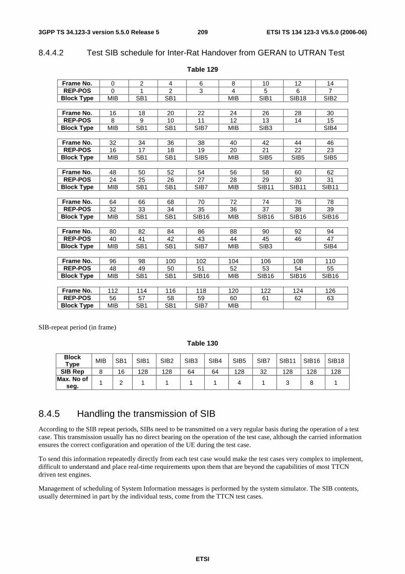
ETSI
ETSI TS 134 123-3 V5.5.0 (2006-06) 2093GPP TS 34.123-3 version 5.5.0 Release 5
8.4.4.2 Test SIB schedule for Inter-Rat Handover from GERAN to UTRAN Test
Table 129
Frame No. 0 2 4 6 8 10 12 14 REP-POS 0 1 2 3 4 5 6 7
Block Type MIB SB1 SB1 MIB SIB1 SIB18 SIB2
Frame No. 16 18 20 22 24 26 28 30 REP-POS 8 9 10 11 12 13 14 15
Block Type MIB SB1 SB1 SIB7 MIB SIB3 SIB4
Frame No. 32 34 36 38 40 42 44 46 REP-POS 16 17 18 19 20 21 22 23
Block Type MIB SB1 SB1 SIB5 MIB SIB5 SIB5 SIB5
Frame No. 48 50 52 54 56 58 60 62 REP-POS 24 25 26 27 28 29 30 31
Block Type MIB SB1 SB1 SIB7 MIB SIB11 SIB11 SIB11
Frame No. 64 66 68 70 72 74 76 78 REP-POS 32 33 34 35 36 37 38 39
Block Type MIB SB1 SB1 SIB16 MIB SIB16 SIB16 SIB16
Frame No. 80 82 84 86 88 90 92 94 REP-POS 40 41 42 43 44 45 46 47
Block Type MIB SB1 SB1 SIB7 MIB SIB3 SIB4
Frame No. 96 98 100 102 104 106 108 110 REP-POS 48 49 50 51 52 53 54 55
Block Type MIB SB1 SB1 SIB16 MIB SIB16 SIB16 SIB16
Frame No. 112 114 116 118 120 122 124 126 REP-POS 56 57 58 59 60 61 62 63
Block Type MIB SB1 SB1 SIB7 MIB
SIB-repeat period (in frame)
Table 130
Block Type MIB SB1 SIB1 SIB2 SIB3 SIB4 SIB5 SIB7 SIB11 SIB16 SIB18
SIB Rep 8 16 128 128 64 64 128 32 128 128 128 Max. No of
seg. 1 2 1 1 1 1 4 1 3 8 1
8.4.5 Handling the transmission of SIB
According to the SIB repeat periods, SIBs need to be transmitted on a very regular basis during the operation of a test case. This transmission usually has no direct bearing on the operation of the test case, although the carried information ensures the correct configuration and operation of the UE during the test case.
To send this information repeatedly directly from each test case would make the test cases very complex to implement, difficult to understand and place real-time requirements upon them that are beyond the capabilities of most TTCN driven test engines.
Management of scheduling of System Information messages is performed by the system simulator. The SIB contents, usually determined in part by the individual tests, come from the TTCN test cases.
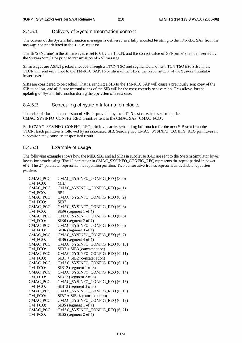
ETSI
ETSI TS 134 123-3 V5.5.0 (2006-06) 2103GPP TS 34.123-3 version 5.5.0 Release 5
8.4.5.1 Delivery of System Information content
The content of the System Information messages is delivered as a fully encoded bit string to the TM-RLC SAP from the message content defined in the TTCN test case.
The IE 'SFNprime' in the SI messages is set to 0 by the TTCN, and the correct value of 'SFNprime' shall be inserted by the System Simulator prior to transmission of a SI message.
SI messages are ASN.1 packed encoded through a TTCN TSO and segmented another TTCN TSO into SIBs in the TTCN and sent only once to the TM-RLC SAP. Repetition of the SIB is the responsibility of the System Simulator lower layers.
SIBs are considered to be cached. That is, sending a SIB to the TM-RLC SAP will cause a previously sent copy of the SIB to be lost, and all future transmissions of the SIB will be the most recently sent version. This allows for the updating of System Information during the operation of a test case.
8.4.5.2 Scheduling of system Information blocks
The schedule for the transmission of SIBs is provided by the TTCN test case. It is sent using the CMAC_SYSINFO_CONFIG_REQ primitive sent to the CMAC SAP (CMAC_PCO).
Each CMAC_SYSINFO_CONFIG_REQ primitive carries scheduling information for the next SIB sent from the TTCN. Each primitive is followed by an associated SIB. Sending two CMAC_SYSINFO_CONFIG_REQ primitives in succession may cause an unspecified result.
8.4.5.3 Example of usage
The following example shows how the MIB, SB1 and all SIBs in subclause 8.4.3 are sent to the System Simulator lower layers for broadcasting. The 1st parameter in CMAC_SYSINFO_CONFIG_REQ represents the repeat period in power of 2. The 2nd parameter represents the repetition position. Two consecutive frames represent an available repetition position.
CMAC_PCO: CMAC_SYSINFO_CONFIG_REQ (3, 0) TM_PCO: MIB CMAC_PCO: CMAC_SYSINFO_CONFIG_REQ (4, 1) TM_PCO: SB1 CMAC_PCO: CMAC_SYSINFO_CONFIG_REQ (6, 2) TM_PCO: SIB7 CMAC_PCO: CMAC_SYSINFO_CONFIG_REQ (6, 3) TM_PCO: SIB6 (segment 1 of 4) CMAC_PCO: CMAC_SYSINFO_CONFIG_REQ (6, 5) TM_PCO: SIB6 (segment 2 of 4) CMAC_PCO: CMAC_SYSINFO_CONFIG_REQ (6, 6) TM_PCO: SIB6 (segment 3 of 4) CMAC_PCO: CMAC_SYSINFO_CONFIG_REQ (6, 7) TM_PCO: SIB6 (segment 4 of 4) CMAC_PCO: CMAC_SYSINFO_CONFIG_REQ (6, 10) TM_PCO: SIB7 + SIB3 (concatenation) CMAC_PCO: CMAC_SYSINFO_CONFIG_REQ (6, 11) TM_PCO: SIB1 + SIB2 (concatenation) CMAC_PCO: CMAC_SYSINFO_CONFIG_REQ (6, 13) TM_PCO: SIB12 (segment 1 of 3) CMAC_PCO: CMAC_SYSINFO_CONFIG_REQ (6, 14) TM_PCO: SIB12 (segment 2 of 3) CMAC_PCO: CMAC_SYSINFO_CONFIG_REQ (6, 15) TM_PCO: SIB12 (segment 3 of 3) CMAC_PCO: CMAC_SYSINFO_CONFIG_REQ (6, 18) TM_PCO: SIB7 + SIB18 (concatenation) CMAC_PCO: CMAC_SYSINFO_CONFIG_REQ (6, 19) TM_PCO: SIB5 (segment 1 of 4) CMAC_PCO: CMAC_SYSINFO_CONFIG_REQ (6, 21) TM_PCO: SIB5 (segment 2 of 4)
ETSI
ETSI TS 134 123-3 V5.5.0 (2006-06) 2113GPP TS 34.123-3 version 5.5.0 Release 5
CMAC_PCO: CMAC_SYSINFO_CONFIG_REQ (6, 22) TM_PCO: SIB5 (segment 3 of 4) CMAC_PCO: CMAC_SYSINFO_CONFIG_REQ (6, 23) TM_PCO: SIB5 (segment 4 of 4) CMAC_PCO: CMAC_SYSINFO_CONFIG_REQ (6, 26) TM_PCO: SIB7 + SIB4 (concatenation) CMAC_PCO: CMAC_SYSINFO_CONFIG_REQ (6, 27) TM_PCO: No segment CMAC_PCO: CMAC_SYSINFO_CONFIG_REQ (6, 29) TM_PCO: SIB11 (segment 1 of 3) CMAC_PCO: CMAC_SYSINFO_CONFIG_REQ (6, 30) TM_PCO: SIB11 (segment 3 of 3) CMAC_PCO: CMAC_SYSINFO_CONFIG_REQ (6, 31) TM_PCO: SIB11 (segment 3 of 3)
8.5 Security in testing The security functions at the SS side are implemented in RLC and MAC layers. When the AM or UM RLC entities and a MAC(d) entity are created, the TTCN will download a security context for each CN domain used. The two ASPs CMAC_SecurityMode_Config_REQ and CRLC_SecurityMode_Config_REQ configures the SS security contexts and associate the contexts to the created entities. The SS shall support one activate security contexts and one context pending activation for each CN domain.
A security context at the SS consists of the security parameter START, 20 bits long and a pair of integrity key and a ciphering key, each 128 bits long. All these security parameters belong to a CS or a PS domain. The SS shall have the ability to store these values till the new values are downloaded and activated. STARTcs is used for initialization of all
counters-C and counters-I (32 bits long each) of all DL and UL radio bearers for ciphering and integrity protection in the CS domain. The same is for STARTps in the PS domain. The TTCN downloads the new START value whenever it
is received from the UE. In the case of a succeeded authentication procedure, the START value is reset to zero by the TTCN.
Once the START is downloaded the SS will, according to the activation time, initialize the 20 most significant bits of the RRC HFN (for integrity protection), the RLC HFN (for ciphering) and the MAC-d HFN (for ciphering) to the START value of the corresponding service domain; the remaining bits are initialized to 0.
Upon the concerned RLC entities and the MAC(d) entity release in the SS, the associated security contexts are no longer used and shall be removed as well. The RLC and the MAC(d) entities are addressed by the TTCN with the cell id = -1.
8.5.1 Authentication
A GMM or MM authentication test step makes use of a number of TSOs to generate an authentication vector:
AV := {RAND, XRES, CK, IK, AUTN}
If the UE has valid authentication parameters (CKSN/KSI), for the respective domain, use of the Authentication procedure after an INITIAL DIRECT TRANSFER message is optional. Authentication in this case will be left to the test case implementation and need not be specified in the prose. However, in the case where the UE does not have valid authentication parameters the Authentication procedure shall be performed.
8.5.2 Ciphering
The ciphering in the SS is activated through the ASP CRLC_Ciphering_Activate_REQ for the AM or UM mode and through CMAC_Ciphering_Activate_REQ for the TM mode.
A PIXIT parameter px_CipheringOnOff indicates whether all the tests are performed under ciphering activated or not. If ciphering should be off at the test execution, the ciphering algorithm in IE ciphering ModeInfo is set to uea0 (no encryption). The UE under test is informed about the SS ciphering capability via IE cipheringAlgorithmCap set to uea0.
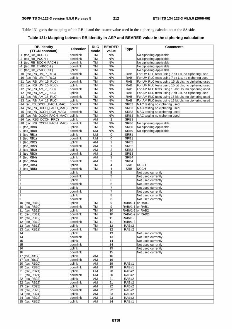
ETSI
ETSI TS 134 123-3 V5.5.0 (2006-06) 2123GPP TS 34.123-3 version 5.5.0 Release 5
Table 131 gives the mapping of the RB id and the bearer value used in the ciphering calculation at the SS side.
Table 131: Mapping between RB identity in ASP and BEARER value in the ciphering calculation
RB identity (TTCN constant) Direction RLC
mode BEARER
value Type Comments
-1 (tsc_RB_BCCH ) downlink TM N/A No ciphering applicable -2 (tsc_RB_PCCH ) downlink TM N/A No ciphering applicable -3 (tsc_RB_BCCH_FACH ) downlink TM N/A No ciphering applicable -4 (tsc_RB_2ndPCCH ) downlink TM N/A No ciphering applicable -5 (tsc_RB_2ndCCCH ) uplink TM N/A No ciphering applicable -10 (tsc_RB_UM_7_RLC) downlink TM N/A RAB For UM RLC tests using 7 bit Lis, no ciphering used -10 (tsc_RB_UM_7_RLC) uplink TM N/A RAB For UM RLC tests using 7 bit LIs, no ciphering used -11 (tsc_RB_UM_15_RLC) downlink TM N/A RAB For UM RLC tests using 15 bit LIs, no ciphering used -11 (tsc_RB_UM_15_RLC) uplink TM N/A RAB For UM RLC tests using 15 bit LIs, no ciphering used -12 (tsc_RB_AM_7_RLC) downlink TM N/A RAB For AM RLC tests using 15 bit LIs, no ciphering used -12 (tsc_RB_AM_7_RLC) uplink TM N/A RAB For AM RLC tests using 7 bit LIs, no ciphering used -13 (tsc_RB_AM_15_RLC) downlink TM N/A RAB For AM RLC tests using 15 bit LIs, no ciphering used -13 (tsc_RB_AM_15_RLC) uplink TM N/A RAB For AM RLC tests using 15 bit LIs, no ciphering used -14 tsc_RB_DCCH_FACH_MAC) downlink TM N/A SRB3 MAC testing no ciphering used -14 (tsc_RB_DCCH_FACH_MAC) uplink TM N/A SRB3 MAC testing no ciphering used -15 (tsc_RB_DCCH_DCH_MAC) downlink TM N/A SRB3 MAC testing no ciphering used -15 (tsc_RB_DCCH_FACH_MAC) uplink TM N/A SRB3 MAC testing no ciphering used -16 (tsc_RB3_DCCH_RRC) uplink AM 2 SRB3 -18 (tsc_RB_CCCH_FACH_MAC) downlink TM N/A SRB0 No ciphering applicable 0 (tsc_RB0) uplink TM N/A SRB0 No ciphering applicable 0 (tsc_RB0) downlink UM N/A SRB0 No ciphering applicable 1 (tsc_RB1) uplink UM 0 SRB1 1 (tsc_RB1) downlink UM 0 SRB1 2 (tsc_RB2) uplink AM 1 SRB2 2 (tsc_RB2) downlink AM 1 SRB2 3 (tsc_RB3) uplink AM 2 SRB3 3 (tsc_RB3) downlink AM 2 SRB3 4 (tsc_RB4) uplink AM 3 SRB4 4 (tsc_RB4) downlink AM 3 SRB4 5 (tsc_RB5) uplink TM 4 SRB DCCH 5 (tsc_RB5) downlink TM 4 SRB DCCH 6 uplink 5 Not used currently 6 downlink 5 Not used currently 7 uplink 6 Not used currently 7 downlink 6 Not used currently 8 uplink 7 Not used currently 8 downlink 7 Not used currently 9 uplink 8 Not used currently 9 downlink 8 Not used currently 10 (tsc_RB10) uplink TM 9 RAB#1-1 or RAB1 10 (tsc_RB10) downlink TM 9 RAB#1-1 or RAB1 11 (tsc_RB11) uplink TM 10 RAB#1-2 or RAB2 11 (tsc_RB11) downlink TM 10 RAB#1-2 or RAB2 12 (tsc_RB12) uplink TM 11 RAB#1-3 12 (tsc_RB12) downlink TM 11 RAB#1-3 13 (tsc_RB13) uplink TM 12 RAB#2 13 (tsc_RB13) downlink TM 12 RAB#2 14 uplink 13 Not used currently 14 downlink 13 Not used currently 15 uplink 14 Not used currently 15 downlink 14 Not used currently 16 uplink 15 Not used currently 16 downlink 15 Not used currently 17 (tsc_RB17) uplink AM 16 17 (tsc_RB17) downlink AM 16 20 (tsc_RB20) uplink AM 19 RAB#1 20 (tsc_RB20) downlink AM 19 RAB#1 21 (tsc_RB21) uplink UM 20 RAB#2 21 (tsc_RB21) downlink UM 20 RAB#2 22 (tsc_RB22) uplink AM 21 RAB#2 22 (tsc_RB22) downlink AM 21 RAB#2 23 (tsc_RB23) uplink AM 22 RAB#2 23 (tsc_RB23) downlink AM 22 RAB#2 24 (tsc_RB24) uplink AM 23 RAB#2 24 (tsc_RB24) downlink AM 23 RAB#2 25 (tsc_RB25) uplink AM 24 RAB#1

ETSI
ETSI TS 134 123-3 V5.5.0 (2006-06) 2133GPP TS 34.123-3 version 5.5.0 Release 5
RB identity (TTCN constant) Direction RLC
mode BEARER
value Type Comments
25 (tsc_RB25) downlink AM 24 RAB#1 26 (tsc_RB26) uplink UM 25 RAB#1 MAC testing no ciphering used 26 (tsc_RB26) downlink UM 25 RAB#1 MAC testing no ciphering used 27 (tsc_RB27) uplink UM 26 RAB#2 MAC testing no ciphering used 27 (tsc_RB27) downlink UM 26 RAB#2 MAC testing no ciphering used 28 (tsc_RB28) uplink UMAM 27 RAB#3 MAC testing no ciphering used 28 (tsc_RB28) downlink UMAM 27 RAB#3 MAC testing no ciphering used 29 uplink 28 Not used yet currently 29 (tsc_RB29) downlink AM 28 SRB0 No ciphering applicable 30 (tsc_RB30) downlink UM N/A CTCH FACH no ciphering used 30 uplink 29 Not used yet currently 31 (tsc_RB31) downlink UM N/A CTCH FACH no ciphering used 31 uplink 30 Not used yet currently 32 downlink 31 Not used yet currently 32 uplink 31 Not used yet currently
8.5.3 Integrity
The integrity protection in the SS is activated through the ASP CRLC_Integrity_Activate_REQ for all SRB.
MAC-I (MessageAuthenticationCode) is calculated by the SS. If the integrity protection is not yet started, the "integrity protection info" IE is omitted in TTCN. If integrity protection is started the TTCN includes the "integrity protection info" IE with all bits set to "0". The SS takes care of all the necessary initialization and calculation on SRBs.
Once integrity is started, the SS initializes and calculates a correct Message Authentication Code, overrides the initial value all bits "0" and inserts a corresponding RRC message sequence number into the IntegrityCheckInfo for all DL DCCH messages. In UL, the SS shall check the received MessageAuthenticationCode. If it is wrong, the ASP CRLC_Integrity_Failure_IND will report having received an UL message with integrity error. If it is correct SS forwards the received messages to the TTCN.
In addition, CRLC_MAC_I_Mode_REQ can be used to force the SS generate wrong DL MAC-I on a specific SRB for the integrity error handling test.
8.5.4 Test security scenarios
Five basic test scenarios are presented in the present document. The corresponding core spec references are found in 3GPP TS 25.331 [21] clauses 8.1.12, 8.2.2.2, 8.5.10.1, 8.5.10.2, 8.6.3.4, 8.6.3.5, 8.6.4.3 and 8.6.4.8.
Start security; RB setup; AM RB reconfiguration; Security modification; SRNS relocation; Modification of RLC size of AM RB during RB reconfiguration; Cell/URA update; InterRAt HO to UTRAN.
As Default, the 1st three basic scenarios can be subdivided into:
Start integrity without ciphering start; Start integrity and ciphering at the same time.
Regarding the simultaneous SRNS relocation, the security scenarios at the relocation are split into:
No security configuration modification; Modification of integrity (FRESH) without ciphering configuration change; Modification integrity FRESH and ciphering algorithm; A security modification pending at the SRNS relocation.
This clause shows the procedures how the security ASP applied to the SS configurations at the different security test scenarios.
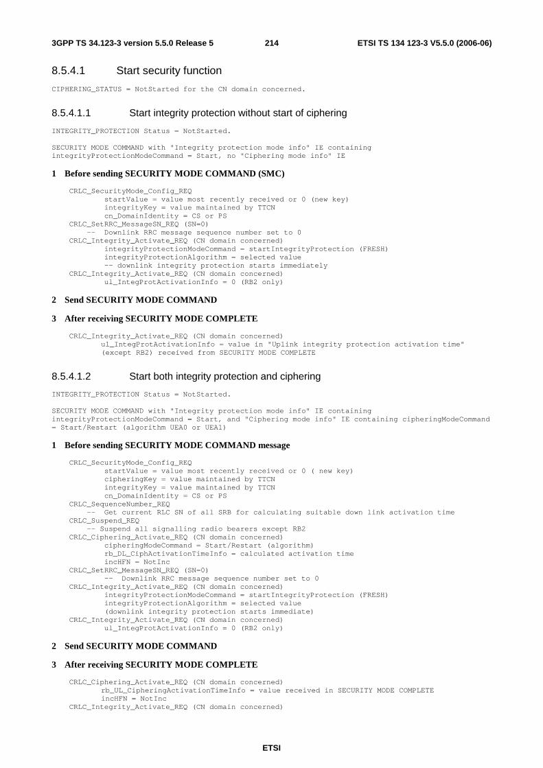
ETSI
ETSI TS 134 123-3 V5.5.0 (2006-06) 2143GPP TS 34.123-3 version 5.5.0 Release 5
8.5.4.1 Start security function
CIPHERING_STATUS = NotStarted for the CN domain concerned.
8.5.4.1.1 Start integrity protection without start of ciphering
INTEGRITY_PROTECTION Status = NotStarted. SECURITY MODE COMMAND with "Integrity protection mode info" IE containing integrityProtectionModeCommand = Start, no "Ciphering mode info" IE
1 Before sending SECURITY MODE COMMAND (SMC)
CRLC_SecurityMode_Config_REQ startValue = value most recently received or 0 (new key) integrityKey = value maintained by TTCN cn_DomainIdentity = CS or PS CRLC_SetRRC_MessageSN_REQ (SN=0) -- Downlink RRC message sequence number set to 0 CRLC_Integrity_Activate_REQ (CN domain concerned) integrityProtectionModeCommand = startIntegrityProtection (FRESH) integrityProtectionAlgorithm = selected value -- downlink integrity protection starts immediately CRLC_Integrity_Activate_REQ (CN domain concerned) ul_IntegProtActivationInfo = 0 (RB2 only)
2 Send SECURITY MODE COMMAND
3 After receiving SECURITY MODE COMPLETE
CRLC_Integrity_Activate_REQ (CN domain concerned) ul_IntegProtActivationInfo = value in "Uplink integrity protection activation time" (except RB2) received from SECURITY MODE COMPLETE
8.5.4.1.2 Start both integrity protection and ciphering
INTEGRITY_PROTECTION Status = NotStarted. SECURITY MODE COMMAND with "Integrity protection mode info" IE containing integrityProtectionModeCommand = Start, and "Ciphering mode info" IE containing cipheringModeCommand = Start/Restart (algorithm UEA0 or UEA1)
1 Before sending SECURITY MODE COMMAND message
CRLC_SecurityMode_Config_REQ startValue = value most recently received or 0 ( new key) cipheringKey = value maintained by TTCN integrityKey = value maintained by TTCN cn_DomainIdentity = CS or PS CRLC_SequenceNumber_REQ -- Get current RLC SN of all SRB for calculating suitable down link activation time CRLC_Suspend_REQ -- Suspend all signalling radio bearers except RB2 CRLC_Ciphering_Activate_REQ (CN domain concerned) cipheringModeCommand = Start/Restart (algorithm) rb_DL_CiphActivationTimeInfo = calculated activation time incHFN = NotInc CRLC_SetRRC_MessageSN_REQ (SN=0) -- Downlink RRC message sequence number set to 0 CRLC_Integrity_Activate_REQ (CN domain concerned) integrityProtectionModeCommand = startIntegrityProtection (FRESH) integrityProtectionAlgorithm = selected value (downlink integrity protection starts immediate) CRLC_Integrity_Activate_REQ (CN domain concerned) ul_IntegProtActivationInfo = 0 (RB2 only)
2 Send SECURITY MODE COMMAND
3 After receiving SECURITY MODE COMPLETE
CRLC_Ciphering_Activate_REQ (CN domain concerned) rb_UL_CipheringActivationTimeInfo = value received in SECURITY MODE COMPLETE incHFN = NotInc
CRLC_Integrity_Activate_REQ (CN domain concerned)
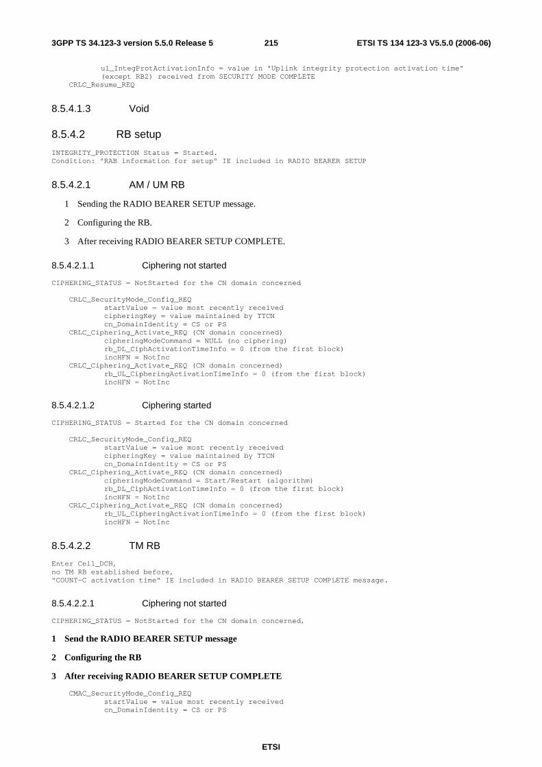
ETSI
ETSI TS 134 123-3 V5.5.0 (2006-06) 2153GPP TS 34.123-3 version 5.5.0 Release 5
ul_IntegProtActivationInfo = value in "Uplink integrity protection activation time" (except RB2) received from SECURITY MODE COMPLETE
CRLC_Resume_REQ
8.5.4.1.3 Void
8.5.4.2 RB setup
INTEGRITY_PROTECTION Status = Started. Condition: "RAB information for setup" IE included in RADIO BEARER SETUP
8.5.4.2.1 AM / UM RB
1 Sending the RADIO BEARER SETUP message.
2 Configuring the RB.
3 After receiving RADIO BEARER SETUP COMPLETE.
8.5.4.2.1.1 Ciphering not started
CIPHERING_STATUS = NotStarted for the CN domain concerned CRLC_SecurityMode_Config_REQ startValue = value most recently received cipheringKey = value maintained by TTCN cn_DomainIdentity = CS or PS CRLC_Ciphering_Activate_REQ (CN domain concerned) cipheringModeCommand = NULL (no ciphering) rb_DL_CiphActivationTimeInfo = 0 (from the first block) incHFN = NotInc CRLC_Ciphering_Activate_REQ (CN domain concerned) rb_UL_CipheringActivationTimeInfo = 0 (from the first block) incHFN = NotInc
8.5.4.2.1.2 Ciphering started
CIPHERING_STATUS = Started for the CN domain concerned CRLC_SecurityMode_Config_REQ startValue = value most recently received cipheringKey = value maintained by TTCN cn_DomainIdentity = CS or PS CRLC_Ciphering_Activate_REQ (CN domain concerned) cipheringModeCommand = Start/Restart (algorithm) rb_DL_CiphActivationTimeInfo = 0 (from the first block) incHFN = NotInc CRLC_Ciphering_Activate_REQ (CN domain concerned) rb_UL_CipheringActivationTimeInfo = 0 (from the first block) incHFN = NotInc
8.5.4.2.2 TM RB
Enter Cell_DCH, no TM RB established before, "COUNT-C activation time" IE included in RADIO BEARER SETUP COMPLETE message.
8.5.4.2.2.1 Ciphering not started
CIPHERING_STATUS = NotStarted for the CN domain concerned,
1 Send the RADIO BEARER SETUP message
2 Configuring the RB
3 After receiving RADIO BEARER SETUP COMPLETE
CMAC_SecurityMode_Config_REQ startValue = value most recently received cn_DomainIdentity = CS or PS

ETSI
ETSI TS 134 123-3 V5.5.0 (2006-06) 2163GPP TS 34.123-3 version 5.5.0 Release 5
CMAC_Ciphering_Activate_REQ (CN domain concerned) incHFN = NotInc cipheringModeCommand = NULL (no ciphering) activationTimeForDPCH = value in "COUNT-C activation time"
8.5.4.2.2.2 Ciphering started
CIPHERING_STATUS = Started for the CN domain concerned,
1 Sending RADIO BEARER SETUP
2 Configuring the RB
CMAC_SecurityMode_Config_REQ startValue = value most recently received cipheringKey = value maintained by TTCN cn_DomainIdentity = CS or PS CMAC_Ciphering_Activate_REQ (CN domain concerned) incHFN = NotInc cipheringModeCommand = Start/Restart (algorithm) activationTimeForDPCH = value in "Activation time" of the RB
3 After receiving RADIO BEARER SETUP COMPLETE message
CMAC_SecurityMode_Config_REQ startValue = value received in response message cipheringKey = value maintained by TTCN cn_DomainIdentity = CS or PS CMAC_Ciphering_Activate_REQ (CN domain concerned) incHFN = IncPerCFN_Cycle cipheringModeCommand = Start/Restart (algorithm) activationTimeForDPCH = value in "COUNT-C activation time"
8.5.4.3 RB Reconfiguration for AM RAB modification of RLC size
CIPHERING_STATUS = Started for the CN domain concerned, "RB mapping info" IE, changeing AM RB RLC size, is included in CELL UPDATE CONFIRM, RADIO REARER RECONFIGURATION, RADIO BEARER RELEASE
8.5.4.3.1 "RB mapping info" in CELL UPDATE CONFIRM
After sending the CELL UPDATE CONFIRM message, re-establish the RB and re-configure the RB with new RLC size and re-initialize COUNT-C for the RB:
CRLC_Config_REQ Release the concerned RB CRLC_Config_REQ Setup the concerned RB (new RLC size) CRLC_SecurityMode_Config_REQ startValue = value received in the CELL UPDATE message integrityKey = value maintained by TTCN cn_DomainIdentity = CS or PS CRLC_Ciphering_Activate_REQ cipheringModeCommand = Start/Restart (existing algorithm) rb_DL_CiphActivationTimeInfo = now incHFN = NotInc CRLC_ Ciphering_Activate_REQ rb_UL_CiphActivationTimeInfo = now incHFN = NotInc
8.5.4.3.2 "RB mapping info" in RB RECONFIGURATION / RELEASE
After receiving the reconfiguration complete message, re-establish the RB and re-configure the RB with new RLC size and re-initialize COUNT-C for the RB:
CRLC_Config_REQ Release the concerned RB CRLC_Config_REQ Setup the concerned RB (new RLC size) CRLC_SecurityMode_Config_REQ

ETSI
ETSI TS 134 123-3 V5.5.0 (2006-06) 2173GPP TS 34.123-3 version 5.5.0 Release 5
startValue = value received in the reconfiguration complete message integrityKey = value maintained by TTCN cn_DomainIdentity = CS or PS CRLC_Ciphering_Activate_REQ cipheringModeCommand = Start/Restart (existing algorithm) rb_DL_CiphActivationTimeInfo = now incHFN = NotInc CRLC_Ciphering_Activate_REQ rb_UL_CiphActivationTimeInfo = now incHFN = NotInc
8.5.4.4 Security modification
Updating security keys is the scenario in this clause.
INTEGRITY_PROTECTION STATUS = Started SECURITY MODE COMMAND contains "Ciphering mode info" IE and/or "Integrity protection mode info" IE
8.5.4.4.1 Integrity started, ciphering not started
CIPHERING_STATUS = NotStarted for the CN domain concerned SECURITY MODE COMMAND with "Integrity protection mode info" IE containing integrityProtectionModeCommand = modify, but "Ciphering mode info" IE absent the same CN domain as in the previous SMC to start integrity protection.
1 Before sending SECURITY MODE COMMAND message
CRLC_SecurityMode_Config_REQ startValue = 0 (new key) integrityKey = new key cn_DomainIdentity = CS or PS CRLC_RRC_MessageSN_REQ -- Get current RRC Message SN for calculation of DL activation time CRLC_Integrity_Activate_REQ (CN domain concerned) integrityProtectionModeCommand = modify
dl_IntegrityProtActivationInfo = now (SRB2), calculated value or a pending activation time set by previous security mode control procedure (SRB2 other than SRB2)
CRLC_Integrity_Activate_REQ (CN domain concerned, RB2) ul_IntegrityProtActivationInfo = now
2 Sending SECURITY MODE COMMAND message
3 After receiving SECURITY MODE COMPLETE
CRLC_Integrity_Activate_REQ (CN domain concerned) ul_IntegProtActivationInfo = value in "Uplink integrity protection activation time" (except RB2)
8.5.4.4.2 Integrity and ciphering started
CIPHERING_STATUS = Started for the CN domain concerned SECURITY MODE COMMAND contains "Integrity protection mode info" IE with integrityProtectionModeCommand = modify, "Ciphering mode info" IE with cipheringModeCommand = Start/Restart.
1 Before sending SECURITY MODE COMMAND message
CRLC_SecurityMode_Config_REQ startValue = 0 (new key) integrityKey = new key cipheringKey = new key cn_DomainIdentity = CS or PS if TM RB exist CMAC_SecurityMode_Config_REQ startValue = 0 ( new key) cipheringKey = new key integrityKey = new key cn_DomainIdentity = CS or PS CRLC_SequenceNumber_REQ -- Get current RLC SN for calculating suitable down link activation time CRLC_Suspend_REQ CRLC_Ciphering_Activate_REQ (CN domain concerned) cipheringModeCommand = Start/Restart (existing algorithm) rb_DL_CiphActivationTimeInfo = calculated activation time

ETSI
ETSI TS 134 123-3 V5.5.0 (2006-06) 2183GPP TS 34.123-3 version 5.5.0 Release 5
incHFN = NotInc CRLC_RRC_MessageSN_REQ -- Get current RRC message SN for calculating suitable DL activation time CRLC_Integrity_Activate_REQ (CN domain concerned) integrityProtectionModeCommand = modify
dl_IntegrityProtActivationInfo = now (SRB2), calculated value or a pending activation time set by previous security mode control procedure (SRB other than SRB2)
CRLC_Integrity_Activate_REQ (CN domain concerned,RB2) ul_IntegrityProtActivationInfo = now if TM RB exist CPHY_Frame_Number_REQ --Get current CFN for calculating suitable activation time for TM RB CMAC_Ciphering_Activate_REQ (CN domain concerned) cipheringModeCommand = Start/Restart (existing algorithm) activationTimeForDPCH = calculated activation time incHFN = IncPerCFN_Cycle
2 Sending SECURITY MODE COMMAND message
3 After receiving SECURITY MODE COMPLETE
CRLC_Ciphering_Activate_REQ (CN domain concerned) rb_UL_CipheringActivationTimeInfo = value received in SECURITY MODE COMPLETE incHFN = NotInc
CRLC_Integrity_Activate_REQ (CN domain concerned, except RB2) ul_IntegProtActivationInfo = value in "Uplink integrity protection activation time"
CRLC_Resume_REQ
8.5.4.5 SRNS relocation
Simultaneous SRNS relocation will take place either "Downlink count synchronization info" IE is received in CELL UPDATE CONFIRM, PHYSICAL CHANNEL RECONFIGURATION, RADIO BEARER SETUP, RADIO BEARER RELEASE, TRANSPORT CHANNEL RECONFIGURATION, URA UPDATE CONFIRM, UTRAN MOBILITY INFROMATION, or "new U-RNTI" IE is received in RADIO BEARER RECONFIGURATION. INTEGRITY_PROTECTION Status = Started
8.5.4.5.1 Void
8.5.4.5.2 Presence of "Integrity protection mode info" but absence of "Ciphering mode info"
SRNS relocation related messages listed contains "Integrity protection mode info" but does not have "Ciphering mode info" IE.
SRNS relocation related message with "Integrity protection mode info" IE containing integrityProtectionModeCommand = Start, but no "Ciphering mode info" IE (no ciphering configuration change).
8.5.4.5.2.1 No security configuration pending
No security configuration pending triggered by previous SECURITY MODE COMMAND.
1 Before sending one of the SRNS relocation related messages
CRLC_SecurityMode_Config_REQ startValue = OMIT (no COUNT-I re-initialization) integrityKey = OMIT or value maintained by TTCN (no key change) cn_DomainIdentity = CS or PS CRLC_Integrity_Activate_REQ (CN domain concerned) integrityProtectionModeCommand = Start (FRESH) integrityProtectionAlgorithm = selected value -- downlink integrity protection starts immediately CRLC_Integrity_Activate_REQ (CN domain concerned) ul_IntegProtActivationInfo = value (now)

ETSI
ETSI TS 134 123-3 V5.5.0 (2006-06) 2193GPP TS 34.123-3 version 5.5.0 Release 5
2 Sending one of the SRNS relocation related messages
3 Re-establishing RB2 and re-initialize COUNT-C for RB2
CRLC_SequenceNumber_REQ CRLC_SequenceNumber_CNF newHFN = MAX(HFN of DL COUNT-C of RB2, HFN of UL COUNT-C of RB2) + 1 CRLC_Config_REQ -- Release RB2 CRLC_Config_REQ -- Setup RB2 CRLC_SecurityMode_Config_REQ startValue = newHFN cn_DomainIdentity = CS or PS concerned CRLC_Ciphering_Activate_REQ (CN domain concerned) if CIPHERING_STATUS= NotStarted cipheringModeCommand = NULL (no ciphering) if CIPHERING_STATUS = Started cipheringModeCommand = Start/Restart (existing algorithm) rb_DL_CiphActivationTimeInfo = now (RB2 only) incHFN = NotInc CRLC_Ciphering_Activate_REQ (CN domain concerned) rb_UL_CipheringActivationTimeInfo = now (RB2 only) incHFN = NotInc
4 Receiving the response message
5 Re-establishing all RBs and SRBs (except SRB2) and re-initialize COUNT-C for all RBs and SRBs (except SRB2)
CRLC_Config_REQ -- Release all RBs and all SRBs (except SRB2) CRLC_Config_REQ -- Setup all RB's and all SRB's (except RB2) CRLC_SecurityMode_Config_REQ startValue = value received in the response message integrityKey = value maintained by TTCN cn_DomainIdentity = CS or PS CRLC_Ciphering_Activate_REQ if CIPHERING_STATUS= NotStarted cipheringModeCommand = NULL (no ciphering) if CIPHERING_STATUS = Started cipheringModeCommand = Start/Restart (existing algorithm) rb_DL_CiphActivationTimeInfo = now (except SRB2) incHFN = NotInc CRLC_Ciphering_Activate_REQ rb_UL_CiphActivationTimeInfo = now (except SRB2) incHFN = NotInc
8.5.4.5.2.2 Pending security configuration (new keys)
A pending security configuration is triggered by the previous SECURITY MODE COMMAND (new Key).
1 Before sending one of the SRNS relocation related messages
CRLC_SecurityMode_Config_REQ startValue = 0 (new key) integrityKey = new key cn_DomainIdentity = CS or PS CRLC_Integrity_Activate_REQ IntegrityProtectionModeCommand = Start (FRESH) IntegrityProtectionAlgorithm = selected value (downlink integrity protection starts
immediately) CRLC_Integrity_Activate_REQ ul_IntegProtActivationInfo = value (now)
2 Send one of the SRNS relocation related messages
3 Re-establish RB2 and re-initialize COUNT-C for RB2
CRLC_SequenceNumber_REQ CRLC_SequenceNumber_CNF HFN = MAX(HFN of DL/UL COUNT-C of RB2) + 1 CRLC_Config_REQ Release RB2

ETSI
ETSI TS 134 123-3 V5.5.0 (2006-06) 2203GPP TS 34.123-3 version 5.5.0 Release 5
CRLC_Config_REQ Setup RB2 CRLC_SecurityMode_Config_REQ startValue = HFN calculated above cipheringKey = new key cn_DomainIdentity = CS or PS CRLC_Ciphering_Activate_REQ if CIPHERING_STATUS= NotStarted cipheringModeCommand = NULL (no ciphering) if CIPHERING_STATUS = Started cipheringModeCommand = Start/Restart (existing algorithm) rb_DL_CiphActivationTimeInfo = now (RB2 only) incHFN = NotInc CRLC_Ciphering_Activate_REQ rb_UL_CipheringActivationTimeInfo = now (RB2 only) incHFN = NotInc
4 Receive the response message
5 Re-establish all RBs and SRBs (except RB2) and re-initialize COUNT-C for all RBs and SRBs (except RB2)
CRLC_Config_REQ Release all RB's and SRB's (except RB2) CRLC_Config_REQ Setup all RB's and SRB's (except RB2) CRLC_SecurityMode_Config_REQ startValue = value received in the response message integrityKey = new key cipheringKey = new key cn_DomainIdentity = CS or PS CRLC_Ciphering_Activate _REQ if CIPHERING_STATUS= NotStarted cipheringModeCommand = NULL (no ciphering) if CIPHERING_STATUS = Started cipheringModeCommand = Start/Restart (existing algorithm) rb_DL_CiphActivationTimeInfo = now (except RB2) incHFN = NotInc CRLC_Ciphering_Activate_REQ rb_UL_CiphActivationTimeInfo = now (except RB2) incHFN = NotInc
6 Re-initialize COUNT-I for all RB's and SRB's (except RB2)
CRLC_SecurityMode_Config_REQ startValue = 0 (new key) integrityKey = new key cn_DomainIdentity = CS or PS CRLC_Integrity_Activate_REQ IntegrityProtectionModeCommand = Start (FRESH) IntegrityProtectionAlgorithm = selected value (downlink integrity protection starts
immediately) CRLC_Integrity_Activate_REQ ul_IntegProtActivationInfo = value (now)
8.5.4.5.2.3 Pending security configuration (no new keys)
A pending security configuration is triggered by the previous SECURITY MODE COMMAND (no new keys).
1 Before sending one of the SRNS relocation related messages
CRLC_SecurityMode_Config_REQ startValue = OMIT (no COUNT-I re-initialization) integrityKey = OMIT or value maintained by TTCN (no key change) cn_DomainIdentity = CS
or PS CRLC_Integrity_Activate_REQ SS_IntegrityProtectionModeCommand = Start (FRESH) IntegrityProtectionAlgorithm = selected value (downlink integrity protection starts
immediately) CRLC_Integrity_Activate_REQ ul_IntegProtActivationInfo = value (now)
2 Send one of the SRNS relocation related messages
3 Re-establish RB2 and re-initialize COUNT-C for RB2
CRLC_SequenceNumber_REQ
ETSI
ETSI TS 134 123-3 V5.5.0 (2006-06) 2213GPP TS 34.123-3 version 5.5.0 Release 5
CRLC_SequenceNumber_CNF HFN = MAX(HFN of DL/UL COUNT-C of RB2) + 1 CRLC_Config_REQ Release RB2 CRLC_Config_REQ Setup RB2 CRLC_SecurityMode_Config_REQ startValue = HFN calculated above cn_DomainIdentity = CS or PS CRLC_Ciphering_Activate_REQ if CIPHERING_STATUS= NotStarted cipheringModeCommand = NULL (no ciphering) if CIPHERING_STATUS = Started cipheringModeCommand = Start/Restart (existing algorithm) rb_DL_CiphActivationTimeInfo = now (RB2 only) incHFN = NotInc CRLC_Ciphering_Activate_REQ rb_UL_CipheringActivationTimeInfo = now (RB2 only) incHFN = NotInc
4 Receive the response message
5 Re-establish all RBs and SRBs (except RB2) and re-initialize COUNT-C for all RBs and SRBs (except RB2)
CRLC_Config_REQ Release all RB's and SRB's (except RB2) CRLC_Config_REQ Setup all RB's and SRB's (except RB2) CRLC_SecurityMode_Config_REQ startValue = value received in the response message integrityKey = value maintained by TTCN cn_DomainIdentity = CS or PS CRLC_Ciphering_Activate_REQ if CIPHERING_STATUS= NotStarted cipheringModeCommand = NULL (no ciphering) if CIPHERING_STATUS = Started cipheringModeCommand = Start/Restart (existing algorithm) rb_DL_CiphActivationTimeInfo = now (except RB2) incHFN = NotInc CRLC_Ciphering_Activate_REQ rb_UL_CiphActivationTimeInfo = now (except RB2) incHFN = NotInc
6 Re-initialize COUNT-I for all RB's and SRB's (except RB2)
CRLC_SecurityMode_Config_REQ startValue = value received in the response message integrityKey = value maintained by TTCN cn_DomainIdentity = CS or PS CRLC_Integrity_Activate_REQ IntegrityProtectionModeCommand = Start (FRESH) IntegrityProtectionAlgorithm = selected value (downlink integrity protection starts
immediately) CRLC_Integrity_Activate_REQ ul_IntegProtActivationInfo = value (now)
8.5.4.5.3 Presence of "Integrity protection mode info" and "Ciphering mode info" IE
CIPHERING_STATUS = Started for the CN domain concerned, SRNS relocation related message with "Integrity protection mode info" IE containing integrityProtectionModeCommand = Start, and "Ciphering mode info" IE containing cipheringModeCommand = Start/Restart (change ciphering algorithm, no "Radio bearer downlink ciphering activation time info")
8.5.4.5.3.1 No security configuration pending
1 Before sending one of the SRNS relocation related messages
CRLC_SecurityMode_Config_REQ startValue = OMIT (no COUNT-I re-initialization) integrityKey = OMIT or value maintained by TTCN (no key change) cn_DomainIdentity = CS or PS CRLC_Integrity_Activate_REQ SS_IntegrityProtectionModeCommand = Start (FRESH)
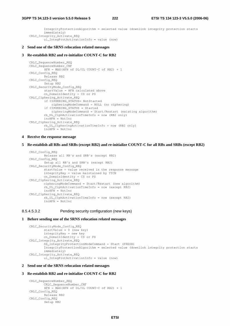
ETSI
ETSI TS 134 123-3 V5.5.0 (2006-06) 2223GPP TS 34.123-3 version 5.5.0 Release 5
IntegrityProtectionAlgorithm = selected value (downlink integrity protection starts immediately)
CRLC_Integrity_Activate_REQ ul_IntegProtActivationInfo = value (now)
2 Send one of the SRNS relocation related messages
3 Re-establish RB2 and re-initialize COUNT-C for RB2
CRLC_SequenceNumber_REQ CRLC_SequenceNumber_CNF HFN = MAX(HFN of DL/UL COUNT-C of RB2) + 1 CRLC_Config_REQ Release RB2 CRLC_Config_REQ Setup RB2 CRLC_SecurityMode_Config_REQ startValue = HFN calculated above cn_DomainIdentity = CS or PS CRLC_Ciphering_Activate_REQ if CIPHERING_STATUS= NotStarted cipheringModeCommand = NULL (no ciphering) if CIPHERING_STATUS = Started cipheringModeCommand = Start/Restart (existing algorithm) rb_DL_CiphActivationTimeInfo = now (RB2 only) incHFN = NotInc CRLC_Ciphering_Activate_REQ rb_UL_CipheringActivationTimeInfo = now (RB2 only) incHFN = NotInc
4 Receive the response message
5 Re-establish all RBs and SRBs (except RB2) and re-initialize COUNT-C for all RBs and SRBs (except RB2)
CRLC_Config_REQ Release all RB's and SRB's (except RB2) CRLC_Config_REQ Setup all RB's and SRB's (except RB2) CRLC_SecurityMode_Config_REQ startValue = value received in the response message integrityKey = value maintained by TTCN cn_DomainIdentity = CS or PS CRLC_Ciphering_Activate_REQ cipheringModeCommand = Start/Restart (new algorithm) rb_DL_CiphActivationTimeInfo = now (except RB2) incHFN = NotInc CRLC_Ciphering_Activate_REQ rb_UL_CiphActivationTimeInfo = now (except RB2) incHFN = NotInc
8.5.4.5.3.2 Pending security configuration (new keys)
1 Before sending one of the SRNS relocation related messages
CRLC_SecurityMode_Config_REQ startValue = 0 (new key) integrityKey = new key cn_DomainIdentity = CS or PS CRLC_Integrity_Activate_REQ SS_IntegrityProtectionModeCommand = Start (FRESH) IntegrityProtectionAlgorithm = selected value (downlink integrity protection starts
immediately) CRLC_Integrity_Activate_REQ ul_IntegProtActivationInfo = value (now)
2 Send one of the SRNS relocation related messages
3 Re-establish RB2 and re-initialize COUNT-C for RB2
CRLC_SequenceNumber_REQ CRLC_SequenceNumber_CNF HFN = MAX(HFN of DL/UL COUNT-C of RB2) + 1 CRLC_Config_REQ Release RB2 CRLC_Config_REQ Setup RB2

ETSI
ETSI TS 134 123-3 V5.5.0 (2006-06) 2233GPP TS 34.123-3 version 5.5.0 Release 5
CRLC_SecurityMode_Config_REQ startValue = HFN calculated above cn_DomainIdentity = CS or PS CRLC_Ciphering_Activate_REQ cipheringModeCommand = NULL (no ciphering status change) rb_DL_CiphActivationTimeInfo = now (RB2 only) incHFN = NotInc CRLC_Ciphering_Activate_REQ rb_UL_CipheringActivationTimeInfo = now (RB2 only) incHFN = NotInc
4 Receive the response message
5 Re-establish all RBs and SRBs (except RB2) and re-initialize COUNT-C for all RBs and SRBs (except RB2)
CRLC_Config_REQ Release all RB's and SRB's (except RB2) CRLC_Config_REQ Setup all RB's and SRB's (except RB2) CRLC_SecurityMode_Config_REQ startValue = 0 integrityKey = new key cn_DomainIdentity = CS or PS CRLC_Ciphering_Activate _REQ cipheringModeCommand = Start/Restart (new algorithm) rb_DL_CiphActivationTimeInfo = now (except RB2) incHFN = NotInc CRLC_Ciphering_Activate_REQ rb_UL_CiphActivationTimeInfo = now (except RB2) incHFN = NotInc
6 Re-initialize COUNT-I for all RBs and SRBs (except RB2)
CRLC_SecurityMode_Config_REQ startValue = 0 (new key) integrityKey = new key cn_DomainIdentity = CS or PS CRLC_Integrity_Activate_REQ IntegrityProtectionModeCommand = Start (FRESH) IntegrityProtectionAlgorithm = selected value (downlink integrity protection starts
immediately) CRLC_Integrity_Activate_REQ ul_IntegProtActivationInfo = value (now)
8.5.4.5.3.3 Pending security configuration (no new key)
1 Before sending one of the SRNS relocation related messages
CRLC_SecurityMode_Config_REQ startValue = OMIT (no COUNT-I re-initialization) integrityKey = OMIT or value maintained by TTCN (no key change) cn_DomainIdentity = CS or PS CRLC_Integrity_Activate_REQ SS_IntegrityProtectionModeCommand = Start (FRESH) IntegrityProtectionAlgorithm = selected value (downlink integrity protection starts
immediately) CRLC_Integrity_Activate_REQ ul_IntegProtActivationInfo = value (now)
2 Send one of the SRNS relocation related messages
3 Re-establish RB2 and re-initialize COUNT-C for RB2
CRLC_SequenceNumber_REQ CRLC_SequenceNumber_CNF HFN = MAX(HFN of DL/UL COUNT-C of RB2) + 1 CRLC_Config_REQ Release RB2 CRLC_Config_REQ Setup RB2 CRLC_SecurityMode_Config_REQ startValue = HFN calculated above n_DomainIdentity = CS or PS CRLC_Ciphering_Activate_REQ if CIPHERING_STATUS= NotStarted cipheringModeCommand = NULL (no ciphering)

ETSI
ETSI TS 134 123-3 V5.5.0 (2006-06) 2243GPP TS 34.123-3 version 5.5.0 Release 5
if CIPHERING_STATUS = Started cipheringModeCommand = Start/Restart (existing algorithm) rb_DL_CiphActivationTimeInfo = now (RB2 only) incHFN = NotInc CRLC_Ciphering_Activate_REQ rb_UL_CipheringActivationTimeInfo = now (RB2 only) incHFN = NotInc
4 Receive the response message
5 Re-establish all RBs and SRBs (except RB2) and re-initialize COUNT-C for all RBs and SRBs (except RB2)
CRLC_Config_REQ Release all RB's and SRB's (except RB2) CRLC_Config_REQ Setup all RB's and SRB's (except RB2) CRLC_SecurityMode_Config_REQ startValue = value received in the response message integrityKey = value maintained by TTCN cn_DomainIdentity = CS or PS CRLC_ Ciphering_Activate _REQ cipheringModeCommand = Start/Restart (new algorithm) rb_DL_CiphActivationTimeInfo = now (except RB2) CRLC_ Ciphering_Activate _REQ rb_UL_CiphActivationTimeInfo = now (except RB2)
6 Re-initialize COUNT-I for all RBs and SRBs (except RB2)
CRLC_SecurityMode_Config_REQ startValue = value received in the response message integrityKey = value maintained by TTCN cn_DomainIdentity = CS or PS CRLC_Integrity_Activate_REQ IntegrityProtectionModeCommand = Start (FRESH) IntegrityProtectionAlgorithm = selected value (downlink integrity protection starts
immediately) CRLC_Integrity_Activate_REQ ul_IntegProtActivationInfo = value (now)
8.5.4.6 CELL/URA update
8.5.4.6.1 RLC re-establish (RB2, RB3, RB4)
"RLC re-establish (RB2, RB3, RB4)" in CELL UPDATE CONFIRM message is set to TRUE CIPHERING_STATUS = Started for the CN domain concerned
1. After sending CELL UPDATE CONFIRM message, re-establish the RB2, RB3 and RB4 (if established)
CRLC_SecurityMode_Config_REQ startValue = value received from CELL UPDATE message cipheringKey = value maintained by TTCN cn_DomainIdentity = CS or PS CRLC_Ciphering_Activate_REQ (CN domain concerned) cipheringModeCommand = Start/Restart (existing algorithm) rb_DL_CiphActivationTimeInfo = now (RB2, RB3, RB4) incHFN = NotInc CRLC_Ciphering_Activate_REQ (CN domain concerned) rb_UL_CipheringActivationTimeInfo = now (RB2, RB3, RB4) incHFN = NotInc
8.5.4.6.2 RLC re-establish (RAB)
"RLC re-establish (RB5 and upwards)" in CELL UPDATE CONFIRM message is set to TRUE CIPHERING_STATUS = Started for the CN domain concerned
1. After sending CELL UPDATE CONFIRM message, re-establish the RAB
CRLC_SecurityMode_Config_REQ startValue = value received from CELL UPDATE message cipheringKey = value maintained by TTCN cn_DomainIdentity = CS or PS CRLC_Ciphering_Activate_REQ (CN domain concerned) cipheringModeCommand = Start/Restart (existing algorithm) rb_DL_CiphActivationTimeInfo = now (RB5 and upwards)

ETSI
ETSI TS 134 123-3 V5.5.0 (2006-06) 2253GPP TS 34.123-3 version 5.5.0 Release 5
incHFN = NotInc CRLC_Ciphering_Activate_REQ (CN domain concerned) rb_UL_CipheringActivationTimeInfo = now (RB5 and upwards) incHFN = NotInc
8.5.4.7 Inter RAT handover to UTRAN
8.5.4.7.1 ciphering has not been activated
ciphering has not been started in the radio access technology from which inter RAT handover is performed. TM mode radio bearer will be established in the UTRAN.
1. Sending HANDOVER TO UTRAN COMMAND in a RAT different from UTRAN
2. After receiving HANDOVER TO UTRAN COMPLETE message
CMAC_SecurityMode_Config_REQ startValue = value received in HANDOVER TO UTRAN COMPLETE message cn_DomainIdentity = CS or PS CMAC_Ciphering_Activate_REQ (CN domain concerned) incHFN = NotInc cipheringModeCommand = NULL activationTimeForDPCH = now CRLC_SecurityMode_Config_REQ startValue = value received in HANDOVER TO UTRAN COMPLETE cn_DomainIdentity = CS or PS CRLC_Ciphering_Activate_REQ (CN domain concerned) cipheringModeCommand = NULL rb_DL_CiphActivationTimeInfo = now (RB1, RB2, RB3, RB4) incHFN = Inc CRLC_Ciphering_Activate_REQ (CN domain concerned) rb_UL_CipheringActivationTimeInfo = now (RB1, RB2, RB3, RB4) incHFN = Inc
8.5.4.7.2 ciphering has been activated
ciphering has been started in the radio access technology from which inter RAT handover is performed. TM mode radio bearer will be established in the UTRAN.
1. Before sending HANDOVER TO UTRAN COMMAND
CRLC_SecurityMode_Config_REQ startValue = "START" value included in the IE "UE security information" in the variable "INTER_RAT_HANDOVER_INFO_TRANSFERRED" cipheringKey = value generated in authentication procedure in GRAN cn_DomainIdentity = CS or PS CRLC_Ciphering_Activate_REQ (CN domain concerned) cipheringModeCommand = Start/Restart (algorithm in HANDOVER TO UTRAN COMMAND) rb_DL_CiphActivationTimeInfo = now (RB1, RB2, RB3, RB4) incHFN = NotInc CRLC_Ciphering_Activate_REQ (CN domain concerned) rb_UL_CipheringActivationTimeInfo = now (RB1, RB2, RB3, RB4) incHFN = NotInc CMAC_SecurityMode_Config_REQ startValue = "START" value included in the IE "UE security information" in the variable "INTER_RAT_HANDOVER_INFO_TRANSFERRED" cipheringKey = value generated in authentication procedure in GRAN cn_DomainIdentity = CS or PS CMAC_Ciphering_Activate_REQ (CN domain concerned) incHFN = NotInc cipheringModeCommand = Start/Restart (algorithm in HANDOVER TO UTRAN COMMAND) activationTimeForDPCH = now
2. Sending HANDOVER TO UTRAN COMMAND in a RAT different from UTRAN
3. After receiving HANDOVER TO UTRAN COMPLETE message
CMAC_SecurityMode_Config_REQ startValue = value received in the response message cipheringKey = value maintained by TTCN cn_DomainIdentity = CS or PS CMAC_Ciphering_Activate_REQ (CN domain concerned) cipheringModeCommand = Start/Restart (algorithm) in HANDOVER TO UTRAN COMMAND) activationTimeForDPCH = value in "COUNT-C activation time" incHFN = IncByOne_IncPerCFN_Cycle
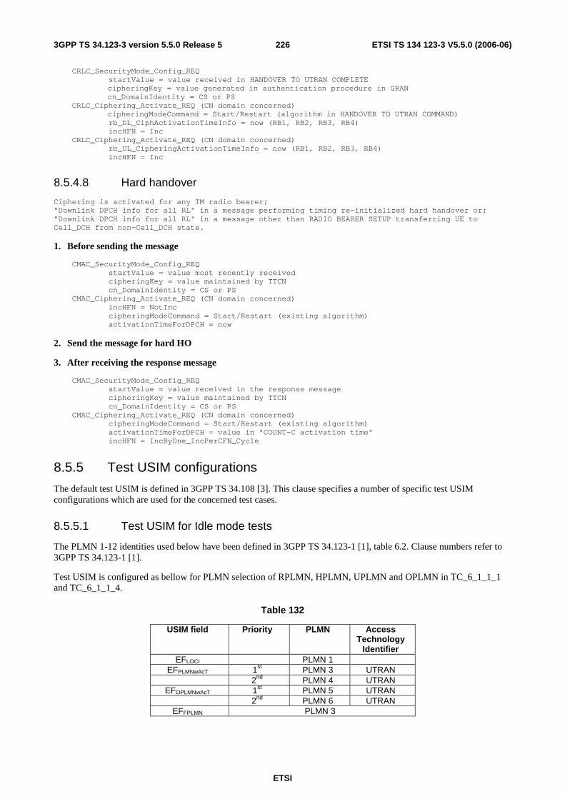
ETSI
ETSI TS 134 123-3 V5.5.0 (2006-06) 2263GPP TS 34.123-3 version 5.5.0 Release 5
CRLC_SecurityMode_Config_REQ startValue = value received in HANDOVER TO UTRAN COMPLETE cipheringKey = value generated in authentication procedure in GRAN cn_DomainIdentity = CS or PS CRLC_Ciphering_Activate_REQ (CN domain concerned) cipheringModeCommand = Start/Restart (algorithm in HANDOVER TO UTRAN COMMAND) rb_DL_CiphActivationTimeInfo = now (RB1, RB2, RB3, RB4) incHFN = Inc CRLC_Ciphering_Activate_REQ (CN domain concerned) rb_UL_CipheringActivationTimeInfo = now (RB1, RB2, RB3, RB4) incHFN = Inc
8.5.4.8 Hard handover
Ciphering is activated for any TM radio bearer; "Downlink DPCH info for all RL" in a message performing timing re-initialized hard handover or; "Downlink DPCH info for all RL" in a message other than RADIO BEARER SETUP transferring UE to Cell_DCH from non-Cell_DCH state.
1. Before sending the message
CMAC_SecurityMode_Config_REQ startValue = value most recently received cipheringKey = value maintained by TTCN cn_DomainIdentity = CS or PS CMAC_Ciphering_Activate_REQ (CN domain concerned) incHFN = NotInc cipheringModeCommand = Start/Restart (existing algorithm) activationTimeForDPCH = now
2. Send the message for hard HO
3. After receiving the response message
CMAC_SecurityMode_Config_REQ startValue = value received in the response message cipheringKey = value maintained by TTCN cn_DomainIdentity = CS or PS CMAC_Ciphering_Activate_REQ (CN domain concerned) cipheringModeCommand = Start/Restart (existing algorithm) activationTimeForDPCH = value in "COUNT-C activation time" incHFN = IncByOne_IncPerCFN_Cycle
8.5.5 Test USIM configurations
The default test USIM is defined in 3GPP TS 34.108 [3]. This clause specifies a number of specific test USIM configurations which are used for the concerned test cases.
8.5.5.1 Test USIM for Idle mode tests
The PLMN 1-12 identities used below have been defined in 3GPP TS 34.123-1 [1], table 6.2. Clause numbers refer to 3GPP TS 34.123-1 [1].
Test USIM is configured as bellow for PLMN selection of RPLMN, HPLMN, UPLMN and OPLMN in TC_6_1_1_1 and TC_6_1_1_4.
Table 132
USIM field Priority PLMN Access Technology
Identifier EFLOCI PLMN 1
EFPLMNwAcT 1st PLMN 3 UTRAN 2nd PLMN 4 UTRAN
EFOPLMNwAcT 1st PLMN 5 UTRAN 2nd PLMN 6 UTRAN
EFFPLMN PLMN 3

ETSI
ETSI TS 134 123-3 V5.5.0 (2006-06) 2273GPP TS 34.123-3 version 5.5.0 Release 5
Test USIM is configured as bellow for PLMN selection of other PLMN with access technology combinations in TC_6_1_1_2.
Table 133
USIM field Priority PLMN Access Technology
Identifier EFLOCI PLMN 6
EFFPLMN PLMN 10
Test USIM is configured as below for automatic PLMN selection of other PLMN with access technology combinations in TC_6_1_1_5.
Table 113a
USIM field Priority PLMN Access Technology
Identifier EFLOCI PLMN 6
Test USIM is configured as bellow for manual PLMN selection independent of RF level and preferred PLMN in TC_6_1_1_3.
Table 134
USIM field Priority PLMN Access Technology
Identifier EFLOCI
EFPLMNwAcT 1st PLMN 3 UTRAN
Test USIM is configured as below for emergency calls in TC_6_1_2_6.
Table 114a
USIM field Priority PLMN EFLOCI PLMN1
EFFPLMN PLMN 3
Test USIMs are configured as bellow for Selection of the correct PLMN and associated RAT in TC_6_2_1_1. Two test USIMs are needed for the test.
Table 135: USIM A
USIM field Priority PLMN Access Technology Identifier
EFLOCI EFHPLMNwAcT 1st GSM EFHPLMNwAcT 2nd UTRAN
Table 136: USIM B
USIM field Priority PLMN Access Technology Identifier
EFLOCI 1st UTRAN EFHPLMNwAcT 2nd
GSM
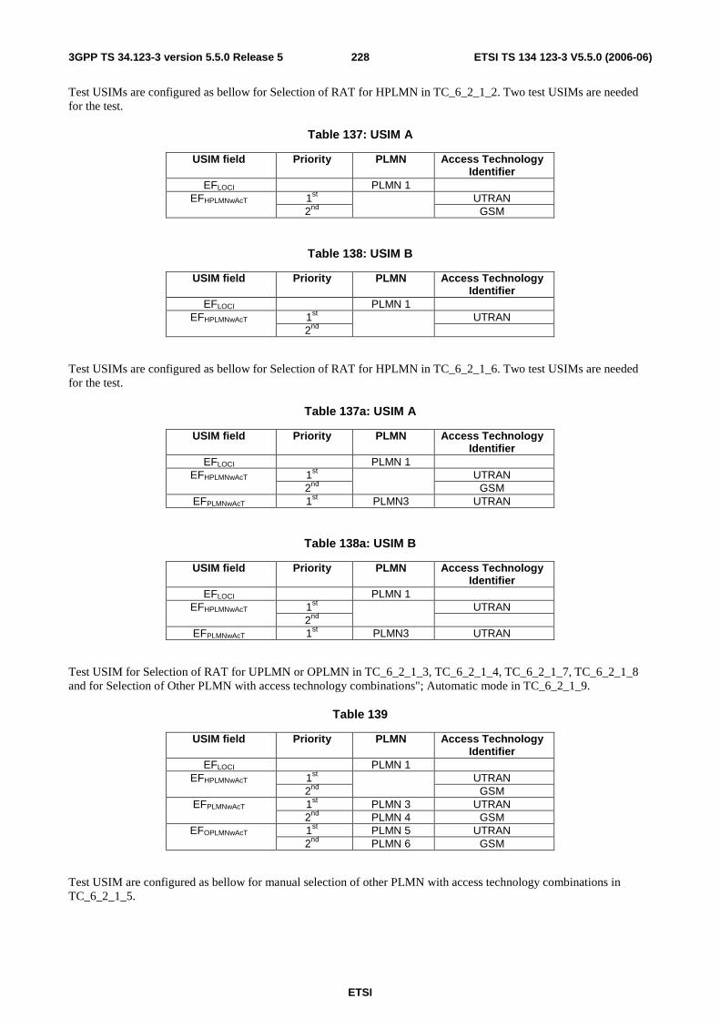
ETSI
ETSI TS 134 123-3 V5.5.0 (2006-06) 2283GPP TS 34.123-3 version 5.5.0 Release 5
Test USIMs are configured as bellow for Selection of RAT for HPLMN in TC_6_2_1_2. Two test USIMs are needed for the test.
Table 137: USIM A
USIM field Priority PLMN Access Technology Identifier
EFLOCI PLMN 1 1st UTRAN EFHPLMNwAcT 2nd
GSM
Table 138: USIM B
USIM field Priority PLMN Access Technology Identifier
EFLOCI PLMN 1 1st UTRAN EFHPLMNwAcT 2nd
Test USIMs are configured as bellow for Selection of RAT for HPLMN in TC_6_2_1_6. Two test USIMs are needed for the test.
Table 137a: USIM A
USIM field Priority PLMN Access Technology Identifier
EFLOCI PLMN 1 1st UTRAN EFHPLMNwAcT 2nd
GSM
EFPLMNwAcT 1st PLMN3 UTRAN
Table 138a: USIM B
USIM field Priority PLMN Access Technology Identifier
EFLOCI PLMN 1 1st UTRAN EFHPLMNwAcT 2nd
EFPLMNwAcT 1st PLMN3 UTRAN
Test USIM for Selection of RAT for UPLMN or OPLMN in TC_6_2_1_3, TC_6_2_1_4, TC_6_2_1_7, TC_6_2_1_8 and for Selection of Other PLMN with access technology combinations"; Automatic mode in TC_6_2_1_9.
Table 139
USIM field Priority PLMN Access Technology Identifier
EFLOCI PLMN 1 1st UTRAN EFHPLMNwAcT 2nd
GSM
1st PLMN 3 UTRAN EFPLMNwAcT 2nd PLMN 4 GSM 1st PLMN 5 UTRAN EFOPLMNwAcT 2nd PLMN 6 GSM
Test USIM are configured as bellow for manual selection of other PLMN with access technology combinations in TC_6_2_1_5.

ETSI
ETSI TS 134 123-3 V5.5.0 (2006-06) 2293GPP TS 34.123-3 version 5.5.0 Release 5
Table 140
USIM field Priority PLMN Access Technology
Identifier EFLOCI PLMN 7
PLMN 8 EFFPLMN PLMN 9
Test USIM for cell reselection if cell becomes barred or for cell reselection timings requires that the USIM does not contain any preferred RAT. This specific test USIM applies to TC_6_2_2_1, TC_6_2_2_2 and TC_6_2_2_3.
8.6 Downlink power setting in SS Refer to 3GPP TS 34.108 [3] clause 6.1.5.

ETSI
ETSI TS 134 123-3 V5.5.0 (2006-06) 2303GPP TS 34.123-3 version 5.5.0 Release 5
8.7 Test suite operation definitions
8.7.1 Test suite operation definitions in the module BasicM
Table 141: TSO definitions in BasicM
TSO Name Description o_AuthRspChk Type of the result: BOOLEAN
Parameters: p_AuthRsp : AuthRsp p_AuthRspExt : AuthRspExt p_K : BITSTRING p_RAND : BITSTRING p_Ext : BOOLEAN Description Checks the input parameter p_AuthRsp and p_AuthRspExt, both received in an Authentication Response, according to the authentication algorithm defined in the following procedure. The extension, p_AuthRspExt, is optional. Its presence is indicated by p_Ext. Returns TRUE if the Authentication Response contained in parameters p_AuthRsp and eventually p_AuthRspExt is correct, FALSE otherwise. The value of tcv_Auth_n indicates whether the AuthRspExt has been provided by the UE or not (n=31, or 31 < n < 128). See 3GPP TS 34.108 [3] clause 8.1.2. If not the parameter p_AuthRspExt is not to be used. Algorithm (without the knowledge of tcv_Auth_n): ========================================= if NOT p_Ext EvaluateAuthRsp else EvaluateAuthRspAndAuthRspExt EvaluateAuthRsp: ============== resultbitstring = o_BitstringXOR(XRES, AuthRsp) if resultbitstring is all 0s then there is a match. EvaluateAuthRspAndAuthRspExt: ============================ XREShigh = o_BitstringXtract(XRES, 32, 32, 0) /* XRES divides into 2 parts: the higher part of 32 bits related to AuthRsp and the lower part related to AuthRspExt \*/ /* SourceLength of 32 is only to ensure usage of the procedure \*/ resultbitstring = o_BitstringXOR(XREShigh, AuthRsp) if resultbitstring is all 0s then there is a match for the first 32 bits:EvaluateAuthRspExt else Authentication failed. EvaluateAuthRspExt: ================= /* As AuthRespExt may not be octet aligned the last octet indicated in AuthRspExt is not used for checking \*/ if (AuthRspExt.iel = 1) then Authentication passed /* there was only 1 possibly incomplete octet which is not used \*/ else { AuthRspExthigh = o_BitstringXtract(AuthRspExt.authRsp, ((AuthRspExt.iel -1)* 8), (AuthRspExt.iel -1)* 8, 0) /* extract (AuthRspExt.iel -1)* 8 bits starting from bit 0 \*/ XRESlow = o_BitstringXtract(XRES, ((AuthRspExt.iel -1)* 8 + 32), (AuthRspExt.iel -1)* 8, 32) /* extract (AuthRspExt.iel -1)* 8 bits starting from bit 32 \*/ resultbitstring = o_BitstringXOR(XRESlow, AuthRspExthigh, (AuthRspExt.iel -1)* 8) if resultbitstring is all 0s then there is a match for the bits following the first 32 bits else Authentication failed
o_BitstringChange Type of the result: BITSTRING Parameters: P_Str: BITSTRING p_Len: INTEGER p_Offset: INTEGER
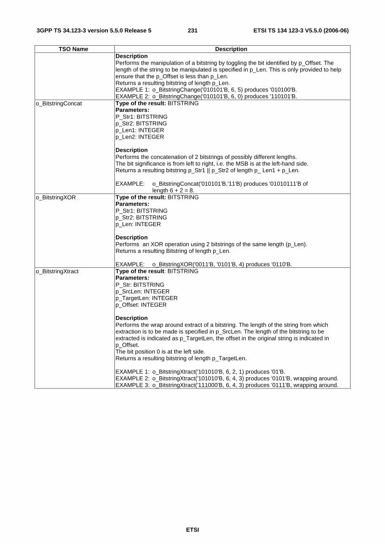
ETSI
ETSI TS 134 123-3 V5.5.0 (2006-06) 2313GPP TS 34.123-3 version 5.5.0 Release 5
TSO Name Description Description Performs the manipulation of a bitstring by toggling the bit identified by p_Offset. The length of the string to be manipulated is specified in p_Len. This is only provided to help ensure that the p_Offset is less than p_Len. Returns a resulting bitstring of length p_Len. EXAMPLE 1: o_BitstringChange('010101'B, 6, 5) produces '010100'B. EXAMPLE 2: o_BitstringChange('010101'B, 6, 0) produces '110101'B.
o_BitstringConcat Type of the result: BITSTRING Parameters: P_Str1: BITSTRING p_Str2: BITSTRING p_Len1: INTEGER p_Len2: INTEGER Description Performs the concatenation of 2 bitstrings of possibly different lengths. The bit significance is from left to right, i.e. the MSB is at the left-hand side. Returns a resulting bitstring p_Str1 || p_Str2 of length p_ Len1 + p_Len. EXAMPLE: o_BitstringConcat('010101'B,'11'B) produces '01010111'B of length 6 + 2 = 8.
o_BitstringXOR Type of the result: BITSTRING Parameters: P_Str1: BITSTRING p_Str2: BITSTRING p_Len: INTEGER Description Performs an XOR operation using 2 bitstrings of the same length (p_Len). Returns a resulting Bitstring of length p_Len. EXAMPLE: o_BitstringXOR('0011'B, '0101'B, 4) produces '0110'B.
o_BitstringXtract Type of the result: BITSTRING Parameters: P_Str: BITSTRING p_SrcLen: INTEGER p_TargetLen: INTEGER p_Offset: INTEGER Description Performs the wrap around extract of a bitstring. The length of the string from which extraction is to be made is specified in p_SrcLen. The length of the bitstring to be extracted is indicated as p_TargetLen, the offset in the original string is indicated in p_Offset. The bit position 0 is at the left side. Returns a resulting bitstring of length p_TargetLen. EXAMPLE 1: o_BitstringXtract('101010'B, 6, 2, 1) produces '01'B. EXAMPLE 2: o_BitstringXtract('101010'B, 6, 4, 3) produces '0101'B, wrapping around. EXAMPLE 3: o_BitstringXtract('111000'B, 6, 4, 3) produces '0111'B, wrapping around.

ETSI
ETSI TS 134 123-3 V5.5.0 (2006-06) 2323GPP TS 34.123-3 version 5.5.0 Release 5
TSO Name Description o_BMC_DrxScheduling Type of the result: BMC_ResultOfSchedulingLevel2
Parameters: p_BMC_CBS_Message1 : BMCCBSMESSAGE p_BMC_CBS_Message2 : BMCCBSMESSAGE p_BMC_CB_RepPeriod : INTEGER p_BMC_NoOfBroadcast_Req : INTEGER p_Offset : BMC_DRX_Offset Description This TSO shall calculate all BMC CBS schedule Messages for the CBS messages as described in 3GPP TS 34.123-1, clause 7.4.3.1. The TSO has to precalculate the CTCH Block SETs needed, i.e. it shall have all necessary knowledge (RLC segmentation, MAC handling, if needed) to predict the CTCH with BMC contents for the given input to be sent. The TSO shall consider the BMC CBS Scheduling Level2 as described in 3GPP TS 25.324 [20], 3GPP TR 25.925 [44] and the description of BMC test architecture and test method in the present document, clause 6.8. The TSO calculates the BMC CBS Schedule messages to predict its next BlockSet to be sent. In addition, a DRX scheduling Bitmap is created for each CTCH allocated TTI aligned to the pre-calculated offset in between 2 CTCH Block Sets. The principle of DRX shall be followed by this TSO. I.e. BMC Messages shall be sent blockwise (CTCH Block Set) with predicted offset in between 2 Block Sets. The TSO shall consider the following aspects to calculate the DRX Selection Bitmap and to create the BMC CBS Schedule messages:
1. The first CTCH Block Set consists of the first BMC CBS Schedule message predicting the offset, length and content of the following Block Set where the BMC CBS Message1 shall be send as new message.
2. The BMC CBS Message1 shall be repeated for p_BMC_CB_RepPeriod multiplied by p_BMC_NoOfBroadcast_Req times before the BMC CBS Message2 is broadcasted.
3. The BMC CBS Schedule Messages shall be the last message of a CTCH Block Set, i.e. on the end of a Block Set.
4. If no further repetition of BMC CBS Messages is needed, no further BMC CBS Schedule message shall be created.
output parameter: DrxSelectionBitmap: The TSO creates a Bitmap as Octetstring for scheduled CTCH allocated TTI as described in 3GPP TS 34.123-3: clause 6.8.2 BMC test method and architecture. CBS_Schedule_Message01, CBS_Schedule_Message02, CBS_Schedule_Message03:Considering the given BMC PDUs BMC_DRX_Offset and BMCCBSMESSAGE to be sent, the BMC Schedule messages have to be created according the given parameter.
o_CheckStringStartWith Type of the result: BOOLEAN Parameters: p_SourceString: IA5String p_StartString : IA5String Description o_CheckStringStartWith returns TRUE if the p_sourceString start with the p_StartString. Otherwise it returns FALSE. EXAMPLE: o_CheckStringStartWith ("+CLCC:1,0,0,2,0;", "+CLCC:1,0,0")=TRUE */.
o_ComputeSM_ContentsSpec
Type of the result: OCTETSTRING Parameters: p_NumOfChars: INTEGER p_Text: IA5String Description This operation provides a short message's contents with a specified number of characters 'p_NumOfChars', each represented by 7 bits. 'p_Text' is used as contents of the short

ETSI
ETSI TS 134 123-3 V5.5.0 (2006-06) 2333GPP TS 34.123-3 version 5.5.0 Release 5
TSO Name Description message. If 'p_Text' contains less than 'p_NumOfChars' characters, 'p_Text' is repeated until the short message reaches the 'p_NumOfChars' characters long. The bits are arranged acc. to 3GPP TS 23.038 [34], clause 6.1.2.1.1. max. 160 characters, i.e. 140 octets.
o_ConcatStrg Type of the result: IA5String Parameters: P_String1: IA5String p_String2: IA5String Description o_ConcatString concatenates 'p_String1' and 'p_String2' and returns the resulting string. EXAMPLE: o_ConcatString ( "AT+CBST=0" , ",0") = "AT+CBST=0,0"
o_ConvertIMSI Type of the result: IMSI_GSM_MAP Parameters: P_Imsi : HEXSTRING The input parameter `p_Imsi` is a BCD string (subset of HEXSTRING), the result is of type IMSI_GSM_MAP.
o_ConvertTMSI Type of the result: TMSI_GSM_MAP Parameters: p_Tmsi : OCTETSTRING Description The input parameter 'p_Tmsi' is an OCTETSTRING; the result is of type TMSI_GSM_MAP.
o_ConvertPTMSI Type of the result: P_TMSI_GSM_MAP Parameters: p_PTMSI : OCTETSTRING Description The input parameter `PTMSI` is a OCTETSTRING, the result is of type P_TMSI_GSM_MAP.
o_ConvtPLMN Type of the result: TMSI_GSM_MAP Parameters: OCTETSTRING p_MCC, p_MNC : HEXSTRING Description the functions of o_ConvtPLMN are as following:
1. The least significant HEX of p_MNC is removed from p_MNC and inserted into p_MCC in the position left to the third HEX to form a new p_MCC of 4 HEXs, then swap the first HEX (left most, most significant Hex) with the second HEX of the new p_MCC.
2. Swap the first Hex with the second HEX of the remaining part of p_MNC and append it to the new p_MCC formed in Step1 above.
EXAMPLE 1: o_ConvtPLMN('123'H, '456'H) = '216354'O. EXAMPLE 2: o_ConvtPLMN ('234'H, '01F'H) = '32F410'O.
o_FirstDigit Type of the result: B4 Parameters: p_BCDdigits : HEXSTRING Description The input parameter p_BCDdigits shall be a BCD string (subset of HEXSTRING), the result is a BITSTRING[4] of a binary representation of one BCD digit. The function of the o_FirstDigit is to return the first (most significant) digit of the input parameter 'p_BCDdigits'. EXAMPLE 1: o_FirstDigit('12345') = '0001'B. EXAMPLE 2: o_FirstDigit('012345678') = '0000'B.

ETSI
ETSI TS 134 123-3 V5.5.0 (2006-06) 2343GPP TS 34.123-3 version 5.5.0 Release 5
TSO Name Description o_GetBit Type of the result: BITSTRING
Parameters: p_Source: BITSTRING p_DataLength: INTEGER Description o_GetBit returns the BITSTRING of length p_DataLength extracted from p_Source. The extraction shall start in the bit position 0 (at the left).
o_GetN_OctetsFromPRBS Type of the result: OCTETSTRING Parameters: p_Start, p_N: INTEGER Description This operation returns N octets from a repeated pseudo random bit sequence, starting with octet position p_Start. The PRBS is the 2047 bit pseudo random test pattern defined in ITU-T Recommendation O.153 [45] for measurements at 64 kbit/s and N x 64 kbit/s o_GetN_OctetsFromPRBS( p_Start, p_N ) generates an OCTETSTRING containing p_N octets starting from octet number p_Start in the PRBS. Requirements p_Start ≥ 0 p_N ≥ 1 Definition Define the 2 047 bit PRBS sequence b(i) as an m-sequence produced by using the following primitive (over GF(2)) generator polynomial of degree 11: X^11 + X^9 + 1 This sequence is defined recursively as: b(i) = 1 , i = 0,1,...,10 b(i) = b(i - 2) + b(i - 11) modulo 2 , i = 11,16,...,2046 The OCTETSTRING, o(j) generated by the present TSO is produced by extracting p_N octets from the repeated sequence b(i) as follows: o(j,k) = b( ( ( n_Start + j ) * 8 + k ) modulo 2047 ) where: j = 0,1,..,p_N - 1 k = 0,1,..7 o(j,k) is the kth bit of the jth octet in o(j), o(j,0) is the MSB of the jth octet in o(j), o(j,7) is the LSB of the jth octet in o(j), Example results: o_GetN_OctetsFromPRBS( 0, 25 ) and o_GetN_OctetsFromPRBS( 2047, 25 ) both return: 'FFE665A5C5CA3452085408ABEECE4B0B813FD337873F2CD1E2'O o_GetN_OctetsFromPRBS( 255, 25 ) and o_GetN_OctetsFromPRBS( 255 + 2047, 25 ) both return '01FFCCCB4B8B9468A410A81157DD9C9617027FA66F0E7E59A3'O
o_GetPI Type of the result: BITSTRING Parameters: p_Imsi : HEXSTRING p_Np: INTEGER Description PI = drx_index mod np The drx_index is calculated as described hereafter: drx_index = (p_Imsi / 8192)) This calculation is defined in TS 25.304 clause 8.3. NOTE: the IMSI is passed as HEXSTRING, the relevant conversion shall be done.
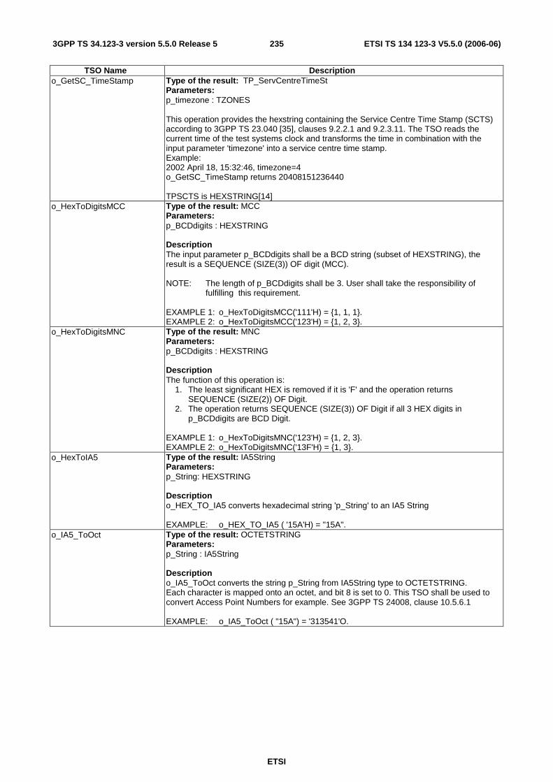
ETSI
ETSI TS 134 123-3 V5.5.0 (2006-06) 2353GPP TS 34.123-3 version 5.5.0 Release 5
TSO Name Description o_GetSC_TimeStamp Type of the result: TP_ServCentreTimeSt
Parameters: p_timezone : TZONES This operation provides the hexstring containing the Service Centre Time Stamp (SCTS) according to 3GPP TS 23.040 [35], clauses 9.2.2.1 and 9.2.3.11. The TSO reads the current time of the test systems clock and transforms the time in combination with the input parameter 'timezone' into a service centre time stamp. Example: 2002 April 18, 15:32:46, timezone=4 o_GetSC_TimeStamp returns 20408151236440 TPSCTS is HEXSTRING[14]
o_HexToDigitsMCC Type of the result: MCC Parameters: p_BCDdigits : HEXSTRING Description The input parameter p_BCDdigits shall be a BCD string (subset of HEXSTRING), the result is a SEQUENCE (SIZE(3)) OF digit (MCC). NOTE: The length of p_BCDdigits shall be 3. User shall take the responsibility of
fulfilling this requirement. EXAMPLE 1: o_HexToDigitsMCC('111'H) = {1, 1, 1}. EXAMPLE 2: o_HexToDigitsMCC('123'H) = {1, 2, 3}.
o_HexToDigitsMNC Type of the result: MNC Parameters: p_BCDdigits : HEXSTRING Description The function of this operation is:
1. The least significant HEX is removed if it is 'F' and the operation returns SEQUENCE (SIZE(2)) OF Digit.
2. The operation returns SEQUENCE (SIZE(3)) OF Digit if all 3 HEX digits in p_BCDdigits are BCD Digit.
EXAMPLE 1: o_HexToDigitsMNC('123'H) = {1, 2, 3}. EXAMPLE 2: o_HexToDigitsMNC('13F'H) = {1, 3}.
o_HexToIA5 Type of the result: IA5String Parameters: p_String: HEXSTRING Description o_HEX_TO_IA5 converts hexadecimal string 'p_String' to an IA5 String EXAMPLE: o_HEX_TO_IA5 ( '15A'H) = "15A".
o_IA5_ToOct Type of the result: OCTETSTRING Parameters: p_String : IA5String Description o_IA5_ToOct converts the string p_String from IA5String type to OCTETSTRING. Each character is mapped onto an octet, and bit 8 is set to 0. This TSO shall be used to convert Access Point Numbers for example. See 3GPP TS 24008, clause 10.5.6.1 EXAMPLE: o_IA5_ToOct ( "15A") = '313541'O.
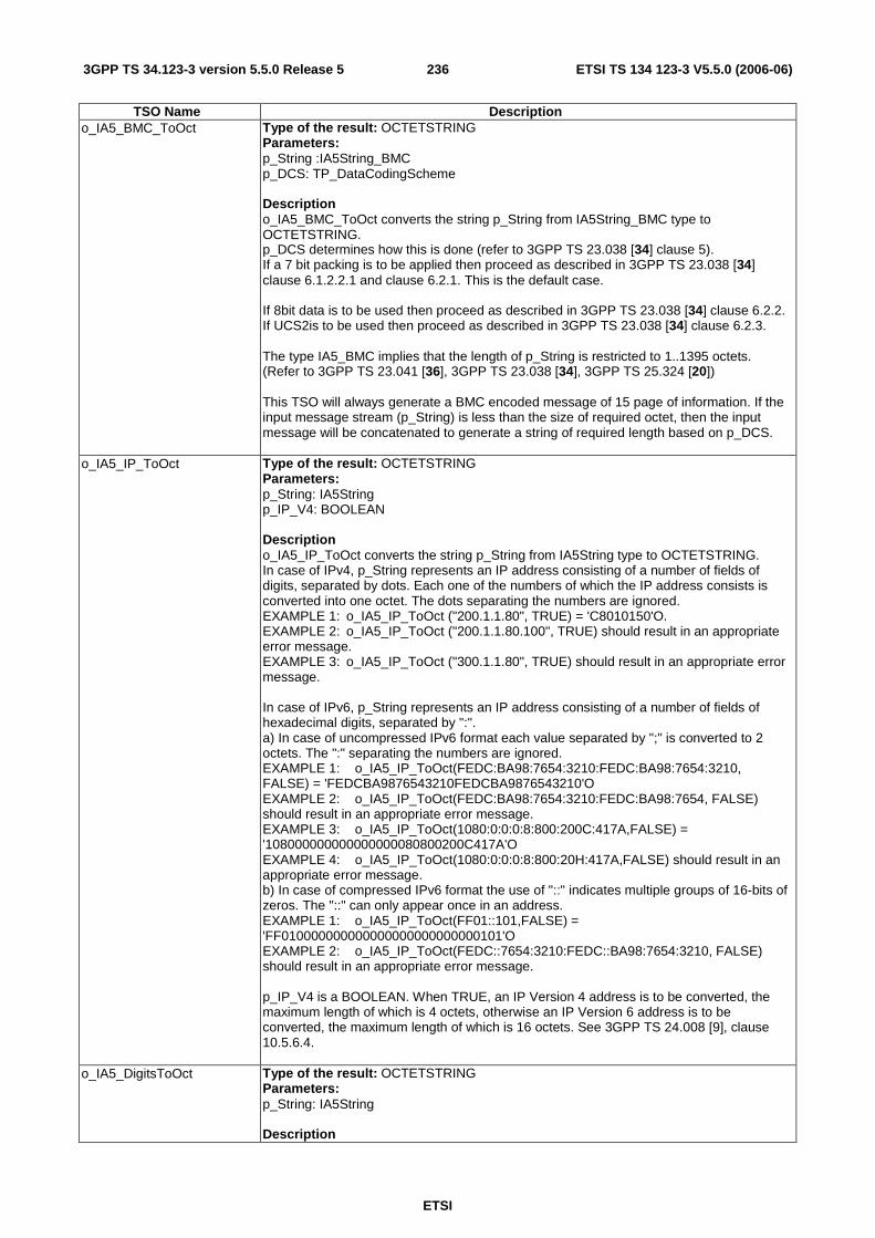
ETSI
ETSI TS 134 123-3 V5.5.0 (2006-06) 2363GPP TS 34.123-3 version 5.5.0 Release 5
TSO Name Description o_IA5_BMC_ToOct Type of the result: OCTETSTRING
Parameters: p_String :IA5String_BMC p_DCS: TP_DataCodingScheme Description o_IA5_BMC_ToOct converts the string p_String from IA5String_BMC type to OCTETSTRING. p_DCS determines how this is done (refer to 3GPP TS 23.038 [34] clause 5). If a 7 bit packing is to be applied then proceed as described in 3GPP TS 23.038 [34] clause 6.1.2.2.1 and clause 6.2.1. This is the default case. If 8bit data is to be used then proceed as described in 3GPP TS 23.038 [34] clause 6.2.2. If UCS2is to be used then proceed as described in 3GPP TS 23.038 [34] clause 6.2.3. The type IA5_BMC implies that the length of p_String is restricted to 1..1395 octets. (Refer to 3GPP TS 23.041 [36], 3GPP TS 23.038 [34], 3GPP TS 25.324 [20]) This TSO will always generate a BMC encoded message of 15 page of information. If the input message stream (p_String) is less than the size of required octet, then the input message will be concatenated to generate a string of required length based on p_DCS.
o_IA5_IP_ToOct Type of the result: OCTETSTRING Parameters: p_String: IA5String p_IP_V4: BOOLEAN Description o_IA5_IP_ToOct converts the string p_String from IA5String type to OCTETSTRING. In case of IPv4, p_String represents an IP address consisting of a number of fields of digits, separated by dots. Each one of the numbers of which the IP address consists is converted into one octet. The dots separating the numbers are ignored. EXAMPLE 1: o_IA5_IP_ToOct ("200.1.1.80", TRUE) = 'C8010150'O. EXAMPLE 2: o_IA5_IP_ToOct ("200.1.1.80.100", TRUE) should result in an appropriate error message. EXAMPLE 3: o_IA5_IP_ToOct ("300.1.1.80", TRUE) should result in an appropriate error message. In case of IPv6, p_String represents an IP address consisting of a number of fields of hexadecimal digits, separated by ":". a) In case of uncompressed IPv6 format each value separated by ";" is converted to 2 octets. The ":" separating the numbers are ignored. EXAMPLE 1: o_IA5_IP_ToOct(FEDC:BA98:7654:3210:FEDC:BA98:7654:3210, FALSE) = 'FEDCBA9876543210FEDCBA9876543210'O EXAMPLE 2: o_IA5_IP_ToOct(FEDC:BA98:7654:3210:FEDC:BA98:7654, FALSE) should result in an appropriate error message. EXAMPLE 3: o_IA5_IP_ToOct(1080:0:0:0:8:800:200C:417A,FALSE) = '108000000000000000080800200C417A'O EXAMPLE 4: o_IA5_IP_ToOct(1080:0:0:0:8:800:20H:417A,FALSE) should result in an appropriate error message. b) In case of compressed IPv6 format the use of "::" indicates multiple groups of 16-bits of zeros. The "::" can only appear once in an address. EXAMPLE 1: o_IA5_IP_ToOct(FF01::101,FALSE) = 'FF010000000000000000000000000101'O EXAMPLE 2: o_IA5_IP_ToOct(FEDC::7654:3210:FEDC::BA98:7654:3210, FALSE) should result in an appropriate error message. p_IP_V4 is a BOOLEAN. When TRUE, an IP Version 4 address is to be converted, the maximum length of which is 4 octets, otherwise an IP Version 6 address is to be converted, the maximum length of which is 16 octets. See 3GPP TS 24.008 [9], clause 10.5.6.4.
o_IA5_DigitsToOct Type of the result: OCTETSTRING Parameters: p_String: IA5String Description
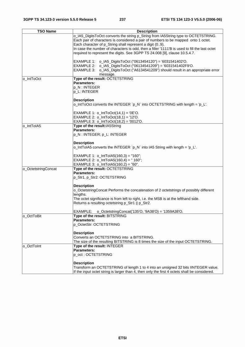
ETSI
ETSI TS 134 123-3 V5.5.0 (2006-06) 2373GPP TS 34.123-3 version 5.5.0 Release 5
TSO Name Description o_IA5_DigitsToOct converts the string p_String from IA5String type to OCTETSTRING. Each pair of characters is considered a pair of numbers to be mapped onto 1 octet. Each character of p_String shall represent a digit (0..9). In case the number of characters is odd, then a filler '1111'B is used to fill the last octet required to represent the digits. See 3GPP TS 24.008 [9], clause 10.5.4.7. EXAMPLE 1: o_IA5_DigitsToOct ("0613454120") = '6031541402'O. EXAMPLE 2: o_IA5_DigitsToOct ("06134541209") = '6031541402F9'O. EXAMPLE 3: o_IA5_DigitsToOct ("A6134541209") should result in an appropriate error
message. o_IntToOct Type of the result: OCTETSTRING
Parameters: p_N : INTEGER p_L: INTEGER Description o_IntToOct converts the INTEGER `p_N` into OCTETSTRING with length = 'p_L'. EXAMPLE 1: o_IntToOct(14,1) = '0E'O. EXAMPLE 2: o_IntToOct(18,1) = '12'O. EXAMPLE 3: o_IntToOct(18,2) = '0012'O.
o_IntToIA5 Type of the result:IA5String Parameters: p_N : INTEGER; p_L: INTEGER Description o_IntToIA5 converts the INTEGER `p_N` into IA5 String with length = 'p_L'. EXAMPLE 1: o_IntToIA5(160,3) = "160"; EXAMPLE 2: o_IntToIA5(160,4) = " 160"; EXAMPLE 3: o_IntToIA5(160,2) = "60".
o_OctetstringConcat Type of the result: OCTETSTRING Parameters: p_Str1, p_Str2: OCTETSTRING Description o_OctetstringConcat Performs the concatenation of 2 octetstrings of possibly different lengths. The octet significance is from left to right, i.e. the MSB is at the lefthand side. Returns a resulting octetstring p_Str1 || p_Str2. EXAMPLE: o_OctetstringConcat('135'O, '9A38'O) = '1359A38'O.
o_OctToBit Type of the result: BITSTRING Parameters: p_OctetStr: OCTETSTRING Description Converts an OCTETSTRING into a BITSTRING. The size of the resulting BITSTRING is 8 times the size of the input OCTETSTRING.
o_OctToInt Type of the result: INTEGER Parameters: p_oct : OCTETSTRING Description Transform an OCTETSTRING of length 1 to 4 into an unsigned 32 bits IINTEGER value. If the input octet string is larger than 4, then only the first 4 octets shall be considered.

ETSI
ETSI TS 134 123-3 V5.5.0 (2006-06) 2383GPP TS 34.123-3 version 5.5.0 Release 5
TSO Name Description o_OeBit Type of the result: BITSTRING
Parameters: p_BCDdigits: HEXSTRING Description The input parameter 'p_BCDdigits' is a BCD string (subset of HEXSTRING), the result is BITSTRING[1]. The function of the o_OeBit is as the follows:
1. It returns '1'B, if the length of the 'p_BCDdigits' is odd. 2. It returns '0'B, if the length of the 'p_BCDdigits' is even.
EXAMPLE 1: o_OeBit('12583') = '1'B. EXAMPLE 2: o_OeBit('87259957') ='0'B.
o_OtherDigits Type of the result: OCTETSTRING Parameters: p_BCDdigits : HEXSTRING Description The input parameter ` p_BCDdigits ` is a BCD string (subset of HEXSTRING), the result is an even string of BCD digits, with eventually a filler 'F'H used. */ The function of the o_OtherDigits is as the follows:
1. If the number of the 'p_BCDdigits' is odd, the operation removes the most significant digit, and then reverses the order of each pair of digits.
2. If the number of the 'p_BCDdigits' is even, first the operation suffixes the `bcddigits` with 'F'H, then removes the most significant digit, and then reverses the order of each pair of digits.
EXAMPLE 1: o_OtherDigi('12345') = '3254', EXAMPLE 2: o_OtherDigi('12345678') ='325476F8'. See o_FirstDigit for the handling of the first digit.
o_RoutingParameterIMSIResponsePaging
Type of the result: RoutingParameter Parameters: p_IMSI : HEXSTRING Description The input parameter p_Imsi is a BCD string (subset of HEXSTRING), the result is of type RoutingParameter. The tso returns the RoutingParameter, which consists of DecimalToBinary [(IMSI div 10) mod 1000]. The bits of the result are numbered from b0 to b9, with bit b0 being the least significant.
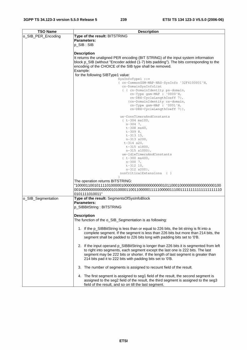
ETSI
ETSI TS 134 123-3 V5.5.0 (2006-06) 2393GPP TS 34.123-3 version 5.5.0 Release 5
TSO Name Description o_SIB_PER_Encoding Type of the result: BITSTRING
Parameters: p_SIB : SIB Description It returns the unaligned PER encoding (BIT STRING) of the input system information block p_SIB (without "Encoder added (1-7) bits padding"). The bits corresponding to the encoding of the CHOICE of the SIB type shall be removed. Example: for the following SIBType1 value: SysInfoType1 ::= { cn-CommonGSM-MAP-NAS-SysInfo '32F4100001'H, cn-DomainSysInfoList { { cn-DomainIdentity ps-domain, cn-Type gsm-MAP : '0000'H, cn-DRX-CycleLengthCoeff 7}, {cn-DomainIdentity cs-domain, cn-Type gsm-MAP : '0001'H, cn-DRX-CycleLengthCoeff 7}}, ue-ConnTimersAndConstants { t-304 ms100, n-304 7, t-308 ms40, t-309 8, t-313 15, n-313 s200, t-314 s20, t-315 s1800, n-315 s1000}, ue-IdleTimersAndConstants { t-300 ms400, n-300 7, t-312 10, n-312 s200}, nonCriticalExtensions { } } The operation returns BITSTRING: "1000011001011110100000100000000000000000001011000100000000000000000100001000000000000000101000011001100000111110000011100111111111111111111100101111010011"
o_SIB_Segmentation Type of the result: SegmentsOfSysInfoBlock Parameters: p_SIBBitString : BITSTRING Description The function of the o_SIB_Segmentation is as following:
1. If the p_SIBBitString is less than or equal to 226 bits, the bit string is fit into a complete segment. If the segment is less than 226 bits but more than 214 bits, the segment shall be padded to 226 bits long with padding bits set to '0'B.
2. If the input operand p_SIBBitString is longer than 226 bits it is segmented from left
to right into segments, each segment except the last one is 222 bits. The last segment may be 222 bits or shorter. If the length of last segment is greater than 214 bits pad it to 222 bits with padding bits set to '0'B.
3. The number of segments is assigned to recount field of the result. 4. The first segment is assigned to seg1 field of the result, the second segment is
assigned to the seg2 field of the result, the third segment is assigned to the seg3 field of the result, and so on till the last segment.

ETSI
ETSI TS 134 123-3 V5.5.0 (2006-06) 2403GPP TS 34.123-3 version 5.5.0 Release 5
TSO Name Description o_SIB_SegmentationFirstSpecial
Type of the result: SegmentsOfSysInfoBlock Parameters: p_SIB_BitString : BITSTRING p_FirstSegLength : INTEGER Description
The function of the o_SIB_Segmentation_FirstShort is as following: 1. If the p_SIB_BitString is less than or equal to p_FirstSegLength bits, the bit string
is fit into one segment. 2. If the input operand p_SIB_BitString is longer than p_FirstSegLength bits it is
segmented from left to right into segments, each segment except the first one and the last one is 222 bits . The first one is p_FirstSegLength long. The last segment may be 222 bits or shorter. If the length of last segment is greater than 214 bits pad it to 222 bits with padding bits set to '0'B.
3. The number of segments is assigned to segCount field of the result. 4. The first segment is assigned to seg1 field of the result, the second segment is assigned to the seg2 field of the result, the third segment is assigned to the seg3 field of the result, and so on till the last segment. 5. The value of parameter p_FirstSegLength shall be less than 197.
o_CheckPDUsAcknowledged
Type of the result: BOOLEAN Parameters: p_NackList: NackList
Contains a list of integers (possibly empty), each of which corresponds to a PDU SN. Negative acknowledgement is expected for each of these PDUs.
p_FSN: INTEGER
Contains an integer representing the first SN expected to be acknowledged. p_LSN: INTEGER
Contains an integer representing the last SN expected to be acknowledged. p_SUFI_List: SuperFields
This parameter contains the received SUFI list to be checked. Description: This TSO is used to check that the given SUFI list contains any combination of SUFIs that fulfils the following requirements:
1. Negatively acknowledges all PDUs whose sequence numbers are in p_NackList. Note that the list may be empty.
2. Positively acknowledges all other PDUs with sequence numbers greater than or
equal to p_FSN, and less than or equal to p_LSN. Output: This TSO returns a BOOLEAN value of TRUE if the SUFI list meets all of the requirements based on the given parameters. Otherwise the TSO returns FALSE.
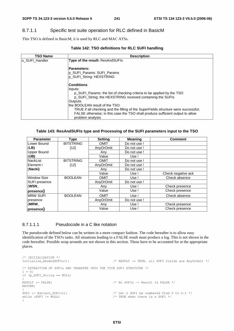
ETSI
ETSI TS 134 123-3 V5.5.0 (2006-06) 2413GPP TS 34.123-3 version 5.5.0 Release 5
8.7.1.1 Specific test suite operation for RLC defined in BasicM
This TSO is defined in BasicM, it is used by RLC and MAC ATSs.
Table 142: TSO definitions for RLC SUFI handling
TSO Name Description o_SUFI_Handler Type of the result: ResAndSUFIs
Parameters: p_SUFI_Params: SUFI_Params p_SUFI_String: HEXSTRING Conditions: Inputs: p_SUFI_Params: the list of checking criteria to be applied by the TSO p_SUFI_String: the HEXSTRING received containing the SUFIs Outputs: the BOOLEAN result of the TSO: TRUE if all checking and the filling of the SuperFields structure were successful; FALSE otherwise; in this case the TSO shall produce sufficient output to allow problem analysis
Table 143: ResAndSUFIs type and Processing of the SUFI parameters input to the TSO
Parameter Type Setting Meaning Comment Lower Bound BITSTRING OMIT Do not use ! (LB) [12] AnyOrOmit Do not use ! Upper Bound Any Do not use ! (UB) Value Use ! NackList BITSTRING OMIT Do not use ! Element i [12] AnyOrOmit Do not use ! (Nacki) Any Do not use ! Value Use ! Check negative ack Window Size BOOLEAN OMIT Use ! Check absence SUFI presence AnyOrOmit Do not use ! (WSN_ Any Use ! Check presence presence) Value Use ! Check presence
MRW SUFI BOOLEAN OMIT Use ! Check absence presence AnyOrOmit Do not use ! (MRW_ Any Use ! Check presence presence) Value Use ! Check presence
8.7.1.1.1 Pseudocode in a C like notation
The pseudocode defined below can be written in a more compact fashion. The code hereafter is to allow easy identification of the TSO's tasks. All situations leading to a FALSE result must produce a log. This is not shown in the code hereafter. Possible wrap arounds are not shown in this section. These have to be accounted for at the appropriate places.
/* INITIALIZATION */ Initialize_ResAndSUFIs(); /* RESULT := TRUE, all SUFI fields are AnyOrOmit */ /* EXTRACTION OF SUFIs AND TRANSFER INTO THE TTCN SUFI STRUCUTRE */ i = 0; if (p_SUFI_String == NULL) { RESULT := FALSE; /* No SUFIs -> Result is FALSE */ RETURN; } SUFI := Extract_SUFI(i); /* Let n SUFI be numbered from 0 to n-1 */ while (SUFI != NULL) /* TRUE when there is a SUFI */ {
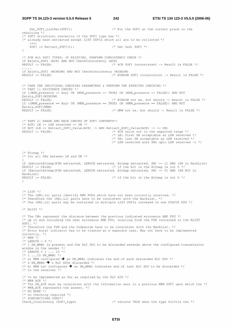
ETSI
ETSI TS 134 123-3 V5.5.0 (2006-06) 2423GPP TS 34.123-3 version 5.5.0 Release 5
Set_SUFI_ListRec(SUFI); /* Put the SUFI at the correct place in the resulting */ /* SUFI structure; overwrite if the SUFI type has */ /* already been extracted except LIST SUFIs which all are to be collected */ i++; SUFI := Extract_SUFI(i); /* Get next SUFI */ } /* FOR ALL SUFI TYPES: IF EXISTING, PERFORM CONSISTENCY CHECK */ if Exists_SUFI (ACK) AND NOT CheckConsistency (ACK) RESULT := FALSE; /* ACK SUFI inconsistent -> Result is FALSE */ ..... if Exists_SUFI (WINDOW) AND NOT CheckConsistency (WINDOW) RESULT := FALSE; /* WINDOW SUFI inconsistent -> Result is FALSE */ /* TAKE THE INDIVIDUAL CHECKING PARAMETERS & PERFORM THE EXPECTED CHECKING */ /* PART 1: EXISTENCE CHECKS */ if ((WSN_presence == Any) OR (WSN_presence == TRUE) OR (WSN_presence == FALSE)) AND NOT Exists_SUFI(WINDOW) RESULT := FALSE; /* WINDOW not ex. but should -> Result is FALSE */ if ((MRW_presence == Any) OR (MRW_presence == TRUE) OR (MRW_presence == FALSE)) AND NOT Exists_SUFI(MRW) RESULT := FALSE; /* MRW not ex. but should -> Result is FALSE */ /* PART 2: RANGE AND NACK CHECKS OF SUFI CONTENTS*/ /* ACK: LB <= LSN received <= UB */ if NOT (LB <= Extract_SUFI_Value(ACK) -1 AND Extract_SUFI_Value(ACK) -1 <= UB) RESULT := FALSE; /* ACK value not in the expected range */ /* LB: first SN acceptable as LSN received */ /* UB: last SN acceptable as LSN received */ /* LSN received acks SNs upto LSN received -1 */ /* Bitmap */ /* for all SNs between LB and UB */ { if (ExtractBitmap(FSN extracted, LENGTH extracted, Bitmap extracted, SN) == 1) AND (SN in NackList) RESULT := FALSE; /* if the bit in the Bitmap is not 0 */ if (ExtractBitmap(FSN extracted, LENGTH extracted, Bitmap extracted, SN) == 0) AND (SN NOT in NackList) RESULT := FALSE; /* if the bit in the Bitmap is not 0 */ } /* LIST */ /* The (SNi,Li) pairs identify AMD PDUs which have not been correctly received. */ /* Therefore the (SNi,Li) pairs have to be consistent with the NackList. */ /* The (SNi,Li) pairs may be contained in multiple LIST SUFIs conveyed in one STATUS PDU */ /* RLIST */ /* The CWs represent the distance between the previous indicated erroneous AMD PDU */ /* up to and including the next erroneous AMD PDU, starting from the FSN contained in the RLIST SUFI. */ /* Therefore the FSN and the Codewords have to be consistent with the NackList. */ /* Error burst indicator has to be treated as a separate case. May not have to be implemented currently. */ /* MRW */ /* LENGTH = 0 */ /* 1 SN_MRWi is present and the RLC SDU to be discarded extends above the configured transmission window in the sender */ /* LENGTH = 1 ... 15 */ /* 1 ...15 SN_MRWi */ /* a) MRW configured � an SN_MRWi indicates the end of each discarded RLC SDU */ /* n SN_MRWs � n RLC SDUs discarded */ /* b) MRW not configured � an SN_MRWi indicates end of last RLC SDU to be discarded */ /* in the receiver */ /* To be implemented as far as required by the RLC ATS */ /* MRW ACK */ /* The SN_ACK must be consistent with the information sent in a previous MRW SUFI upon which the */ /* MRW_ACK represents the answer. */ /* NO MORE */ /* no checking required */ /* SUBFUNCTIONS USED*/ Check_Consistency (SUFI_type) /* returns TRUE when the type fulfils the */
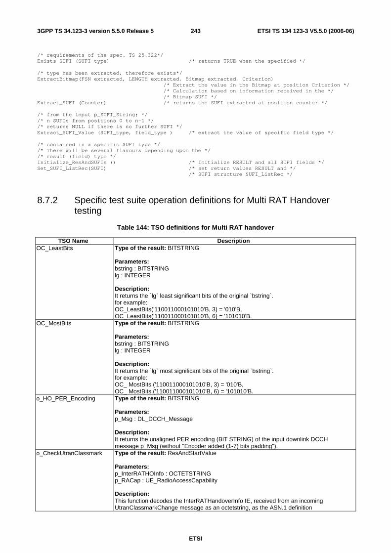
ETSI
ETSI TS 134 123-3 V5.5.0 (2006-06) 2433GPP TS 34.123-3 version 5.5.0 Release 5
/* requirements of the spec. TS 25.322*/ Exists_SUFI (SUFI_type) /* returns TRUE when the specified */ /* type has been extracted, therefore exists*/ ExtractBitmap(FSN extracted, LENGTH extracted, Bitmap extracted, Criterion) /* Extract the value in the Bitmap at position Criterion */ /* Calculation based on information received in the */ /* Bitmap SUFI */ Extract_SUFI (Counter) /* returns the SUFI extracted at position counter */ /* from the input p_SUFI_String; */ /* n SUFIs from positions 0 to n-1 */ /* returns NULL if there is no further SUFI */ Extract_SUFI_Value (SUFI_type, field_type ) /* extract the value of specific field type */ /* contained in a specific SUFI type */ /* There will be several flavours depending upon the */ /* result (field) type */ Initialize_ResAndSUFIs () /* Initialize RESULT and all SUFI fields */ Set_SUFI_ListRec(SUFI) /* set return values RESULT and */ /* SUFI structure SUFI_ListRec */
8.7.2 Specific test suite operation definitions for Multi RAT Handover testing
Table 144: TSO definitions for Multi RAT handover
TSO Name Description OC_LeastBits Type of the result: BITSTRING
Parameters: bstring : BITSTRING lg : INTEGER Description: It returns the `lg` least significant bits of the original `bstring`. for example: OC_LeastBits('110011000101010'B, 3) = '010'B, OC_LeastBits('110011000101010'B, 6) = '101010'B.
OC_MostBits Type of the result: BITSTRING Parameters: bstring : BITSTRING lg : INTEGER Description: It returns the `lg` most significant bits of the original `bstring`. for example: OC_ MostBits ('110011000101010'B, 3) = '010'B, OC_ MostBits ('110011000101010'B, 6) = '101010'B.
o_HO_PER_Encoding Type of the result: BITSTRING Parameters: p_Msg : DL_DCCH_Message Description: It returns the unaligned PER encoding (BIT STRING) of the input downlink DCCH message p_Msg (without "Encoder added (1-7) bits padding").
o_CheckUtranClassmark Type of the result: ResAndStartValue Parameters: p_InterRATHOInfo : OCTETSTRING p_RACap : UE_RadioAccessCapability Description: This function decodes the InterRATHandoverInfo IE, received from an incoming UtranClassmarkChange message as an octetstring, as the ASN.1 definition
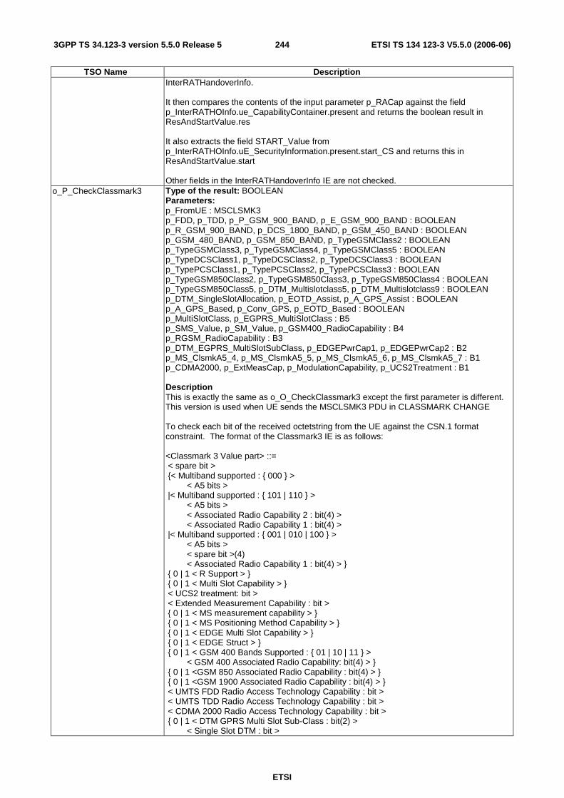
ETSI
ETSI TS 134 123-3 V5.5.0 (2006-06) 2443GPP TS 34.123-3 version 5.5.0 Release 5
TSO Name Description InterRATHandoverInfo. It then compares the contents of the input parameter p_RACap against the field p_InterRATHOInfo.ue_CapabilityContainer.present and returns the boolean result in ResAndStartValue.res It also extracts the field START_Value from p_InterRATHOInfo.uE_SecurityInformation.present.start_CS and returns this in ResAndStartValue.start Other fields in the InterRATHandoverInfo IE are not checked.
o_P_CheckClassmark3 Type of the result: BOOLEAN Parameters: p_FromUE : MSCLSMK3 p_FDD, p_TDD, p_P_GSM_900_BAND, p_E_GSM_900_BAND : BOOLEAN p_R_GSM_900_BAND, p_DCS_1800_BAND, p_GSM_450_BAND : BOOLEAN p_GSM_480_BAND, p_GSM_850_BAND, p_TypeGSMClass2 : BOOLEAN p_TypeGSMClass3, p_TypeGSMClass4, p_TypeGSMClass5 : BOOLEAN p_TypeDCSClass1, p_TypeDCSClass2, p_TypeDCSClass3 : BOOLEAN p_TypePCSClass1, p_TypePCSClass2, p_TypePCSClass3 : BOOLEAN p_TypeGSM850Class2, p_TypeGSM850Class3, p_TypeGSM850Class4 : BOOLEAN p_TypeGSM850Class5, p_DTM_Multislotclass5, p_DTM_Multislotclass9 : BOOLEAN p_DTM_SingleSlotAllocation, p_EOTD_Assist, p_A_GPS_Assist : BOOLEAN p_A_GPS_Based, p_Conv_GPS, p_EOTD_Based : BOOLEAN p_MultiSlotClass, p_EGPRS_MultiSlotClass : B5 p_SMS_Value, p_SM_Value, p_GSM400_RadioCapability : B4 p_RGSM_RadioCapability : B3 p_DTM_EGPRS_MultiSlotSubClass, p_EDGEPwrCap1, p_EDGEPwrCap2 : B2 p_MS_ClsmkA5_4, p_MS_ClsmkA5_5, p_MS_ClsmkA5_6, p_MS_ClsmkA5_7 : B1 p_CDMA2000, p_ExtMeasCap, p_ModulationCapability, p_UCS2Treatment : B1 Description This is exactly the same as o_O_CheckClassmark3 except the first parameter is different. This version is used when UE sends the MSCLSMK3 PDU in CLASSMARK CHANGE To check each bit of the received octetstring from the UE against the CSN.1 format constraint. The format of the Classmark3 IE is as follows: <Classmark 3 Value part> ::= < spare bit > {< Multiband supported : { 000 } > < A5 bits > |< Multiband supported : { 101 | 110 } > < A5 bits > < Associated Radio Capability 2 : bit(4) > < Associated Radio Capability 1 : bit(4) > |< Multiband supported : { 001 | 010 | 100 } > < A5 bits > < spare bit >(4) < Associated Radio Capability 1 : bit(4) > } { 0 | 1 < R Support > } { 0 | 1 < Multi Slot Capability > } < UCS2 treatment: bit > < Extended Measurement Capability : bit > { 0 | 1 < MS measurement capability > } { 0 | 1 < MS Positioning Method Capability > } { 0 | 1 < EDGE Multi Slot Capability > } { 0 | 1 < EDGE Struct > } { 0 | 1 < GSM 400 Bands Supported : { 01 | 10 | 11 } > < GSM 400 Associated Radio Capability: bit(4) > } { 0 | 1 <GSM 850 Associated Radio Capability : bit(4) > } { 0 | 1 <GSM 1900 Associated Radio Capability : bit(4) > } < UMTS FDD Radio Access Technology Capability : bit > < UMTS TDD Radio Access Technology Capability : bit > < CDMA 2000 Radio Access Technology Capability : bit > { 0 | 1 < DTM GPRS Multi Slot Sub-Class : bit(2) > < Single Slot DTM : bit >

ETSI
ETSI TS 134 123-3 V5.5.0 (2006-06) 2453GPP TS 34.123-3 version 5.5.0 Release 5
TSO Name Description { 0 | 1< DTM EGPRS Multi Slot Sub-Class : bit(2) > } } { 0 | 1 < Single Band Support > } < spare bit >** ; < A5 bits > ::= < A5/7 : bit > < A5/6 : bit > < A5/5 : bit > < A5/4 : bit > ; <R Support>::= < R-GSM band Associated Radio Capability : bit(3) > ; < Multi Slot Capability > ::= < Multi Slot Class : bit(5) > ; < MS Measurement capability > ::= < SMS_VALUE : bit (4) > < SM_VALUE : bit (4) > ; < MS Positioning Method Capability > ::= < MS Positioning Method : bit(5) > ; < EDGE Multi Slot Capability > ::= < EDGE Multi Slot Class : bit(5) > ; <EDGE Struct> : := < Modulation Capability : bit > { 0 | 1 < EDGE RF Power Capability 1: bit(2) > } { 0 | 1 < EDGE RF Power Capability 2: bit(2) > } ; < Single Band Support > ::= < GSMBand : bit(4) > ;
o_PacketPagingGroupCalculate
Type of the result: INTEGER Parameters: IMSI : HEXSTRING KC_Conf : INTEGER M : INTEGER N : INTEGER SplitPGCycle : B8 Description: It returns the calculated Packet Paging Group, according to: PAGING_GROUP (0 ... M-1) = ( ( (IMSI mod 1000) div (KC*N) ) * N + (IMSI mod 1000) mod N + Max((m * M) div SPLIT_PG_CYCLE, m)) mod M for m = 0, ... , Min(M, SPLIT_PG_CYCLE) -1 where KC = number of (P)CCCH in the cell = BS_PCC_CHANS for PCCCH or BS_CC_CHANS for CCCH M = number of paging blocks "available" on one (P)CCCH = (12 - BS_PAG_BLKS_RES - BS_PBCCH_BLKS) * 64 for PCCCH (9 - BS_AG_BLKS_RES) * 64 for CCCH not combined (3 - BS_AG_BLKS_RES) * 64 for CCCH + SDCCH combined N=1 for PCCCH (9 - BS_AG_BLKS_RES)*BS_PA_MFRMS for CCCH not combined (3 - BS_AG_BLKS_RES)*BS_PA_MFRMS for CCCH/SDCCH combined SPLIT_PG_CYCLE is an MS specific parameter negotiated at GPRS attach (see 3GPP TS 04.60) IMSI = International Mobile Subscriber Identity, as defined in 3GPP TS 03.03.
o_PagingGroupCalculate Type of the result: INTEGER Parameters: p_IMSI : HEXSTRING p_CCCH_Conf : B_3 p_N : INTEGER Description Calculate the PAGING_GROUP (0 .. N?1) = ((IMSI mod 1000) mod (BS_CC_CHANS x N)) mod N where : N = number of paging blocks "available" on one CCCH = (number of paging blocks "available" in a 51-multiframe on one CCCH) x BS_PA_MFRMS. IMSI = International Mobile Subscriber Identity, as defined in 3GPP TS 23.003 [6]. mod = Modulo.
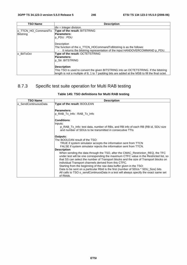
ETSI
ETSI TS 134 123-3 V5.5.0 (2006-06) 2463GPP TS 34.123-3 version 5.5.0 Release 5
TSO Name Description div = Integer division.
o_TTCN_HO_CommandToBitstring
Type of the result: BITSTRING Parameters: p_PDU : PDU Description The function of the o_TTCN_HOCommandToBitstring is as the follows:
- It returns the bitstring representation of the input HANDOVERCOMMAND p_PDU. o_BitToOct Type of the result: OCTETSTRING
Parameters: p_Str: BITSTRING Description This TSO is used to convert the given BITSTRING into an OCTETSTRING. If the bitstring length is not a multiple of 8, 1 to 7 padding bits are added at the MSB to fill the final octet.
8.7.3 Specific test suite operation for Multi RAB testing
Table 145: TSO definitions for Multi RAB testing
TSO Name Description o_SendContinuousData Type of the result: BOOLEAN
Parameters: p_RAB_Tx_Info : RAB_Tx_Info Conditions: Inputs: p_RAB_Tx_Info: test data, number of RBs, and RB info of each RB (RB id, SDU size
and number of SDUs to be transmitted in consecutive TTIs Outputs: The BOOLEAN result of the TSO: TRUE if system simulator accepts the information sent from TTCN FALSE if system simulator rejects the information sent from TTCN. Description When sending the data through the TSO, after the CMAC_Restriction_REQ, the TFC under test will be one corresponding the maximum CTFC value in the Restricted list, so that SS can select the number of Transport blocks and the size of Transport blocks on individual Transport channels derived from this CTFC. Starting from the beginning of the raw data buffer given in the TSO: Data to be sent on a particular RbId is the first (number of SDUs * SDU_Size) bits All calls to TSO o_sendContinuosData in a test will always specify the exact same set of RbIds.
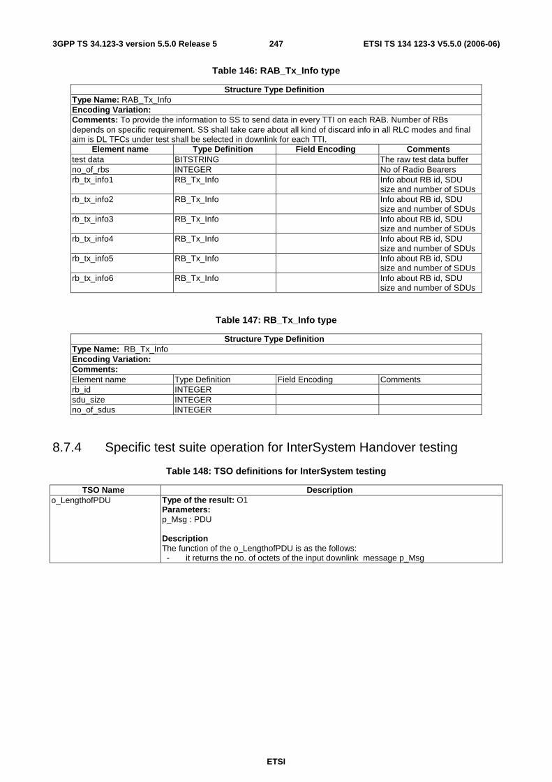
ETSI
ETSI TS 134 123-3 V5.5.0 (2006-06) 2473GPP TS 34.123-3 version 5.5.0 Release 5
Table 146: RAB_Tx_Info type
Structure Type Definition Type Name: RAB_Tx_Info Encoding Variation: Comments: To provide the information to SS to send data in every TTI on each RAB. Number of RBs depends on specific requirement. SS shall take care about all kind of discard info in all RLC modes and final aim is DL TFCs under test shall be selected in downlink for each TTI.
Element name Type Definition Field Encoding Comments test data BITSTRING The raw test data buffer no_of_rbs INTEGER No of Radio Bearers rb_tx_info1 RB_Tx_Info Info about RB id, SDU
size and number of SDUs rb_tx_info2 RB_Tx_Info Info about RB id, SDU
size and number of SDUs rb_tx_info3 RB_Tx_Info Info about RB id, SDU
size and number of SDUs rb_tx_info4 RB_Tx_Info Info about RB id, SDU
size and number of SDUs rb_tx_info5 RB_Tx_Info Info about RB id, SDU
size and number of SDUs rb_tx_info6 RB_Tx_Info Info about RB id, SDU
size and number of SDUs
Table 147: RB_Tx_Info type
Structure Type Definition Type Name: RB_Tx_Info Encoding Variation: Comments: Element name Type Definition Field Encoding Comments rb_id INTEGER sdu_size INTEGER no_of_sdus INTEGER
8.7.4 Specific test suite operation for InterSystem Handover testing
Table 148: TSO definitions for InterSystem testing
TSO Name Description o_LengthofPDU Type of the result: O1
Parameters: p_Msg : PDU Description The function of the o_LengthofPDU is as the follows: - it returns the no. of octets of the input downlink message p_Msg

ETSI
ETSI TS 134 123-3 V5.5.0 (2006-06) 2483GPP TS 34.123-3 version 5.5.0 Release 5
8.7.5 Specific test suite operation for RAB_HS testing
Table 149: TSO definitions for RAB_HS testing
TSO Name Description o_CalculateTestPoint656 Type of the result: HSDPA_TestPoint
Parameters: p_PhyCat:HSDSCH_physical_layer_category p_ModScheme:ModulationScheme p_NumOfPDU: INTEGER Description: TSO implements tables 14.1.3.4.1 for category 1 to 6, 14.1.3.4.2 for category 7 and 8, 14.1.3.4.3 for category 9, 14.1.3.4.4 for Category 10 and 14.1.3.4.5 for category 11 and 12. It accepts UE category(1 to 12), Modulation scheme(qpsk or qam16) and number of MAC-D PDU's( 1 to 70) as input. If a test point is not defined for this combination of input, then returns flag = FALSE noOfChannelisatonCodes =0 tbSizeIndexOnHS_SCCH =0 If a test point is defined for the combination of inputs, it returns, flag = TRUE noOfChannelisatonCodes =value as per relevant table tbSizeIndexOnHS_SCCH =TFRI value as per relevant table example: if input is physical category =1,modScheme=qpsk,Num Of PDU's =5 TSO returns flag = TRUE noOfChannelisatonCodes =5 tbSizeIndexOnHS_SCCH =43 If input is category =1,modScheme=qpsk,Num Of PDU's =10 TSO returns flag = FALSE noOfChannelisatonCodes =0 tbSizeIndexOnHS_SCCH =0
o_CalculateTestPoint336 Type of the result: HSDPA_TestPoint Parameters: p_PhyCat:HSDSCH_physical_layer_category p_ModScheme:ModulationScheme p_NumOfPDU: INTEGER Description: TSO implements tables 14.1.3.3.1 for category 1 to 6, 14.1.3.3.2 for category 7 and 8, 14.1.3.3.3 for category 9, 14.1.3.3.4 for Category 10 and 14.1.3.3.5 for category 11 and 12. It accepts UE category(1 to 12), Modulation scheme(qpsk or qam16) and number of MAC-D PDU's( 1 to 70) as input. If a test point is not defined for this combination of input, then returns flag = FALSE noOfChannelisatonCodes =0 tbSizeIndexOnHS_SCCH =0 If a test point is defined for the combination of inputs, it returns, flag = TRUE noOfChannelisatonCodes =value as per relevant table tbSizeIndexOnHS_SCCH =TFRI value as per relevant table example: if input is physical category =1,modScheme=qpsk,Num Of PDU's =10 TSO returns flag = TRUE noOfChannelisatonCodes =5 tbSizeIndexOnHS_SCCH =45 If input is category =1,modScheme=qpsk,Num Of PDU's =17 TSO returns flag = FALSE noOfChannelisatonCodes =0

ETSI
ETSI TS 134 123-3 V5.5.0 (2006-06) 2493GPP TS 34.123-3 version 5.5.0 Release 5
tbSizeIndexOnHS_SCCH =0
Table 150: HSDPA_TestPoint
Structure Type Definition Type Name: HSDPA_TestPoint Encoding Variation: Comments: To provide the information to SS to send data in every TTI on each RAB. Number of RBs depends on specific requirement. SS shall take care about all kind of discard info in all RLC modes and final aim is DL TFCs under test shall be selected in downlink for each TTI.
Element name Type Definition Field Encoding Comments flag BOOLEAN TRUE if test point is
applicable noOfChannelisatonCodes INTEGER Range 1 to 15
Valid value ifflag =TRUE tbSizeIndexOnHS_SCCH INTEGER
8.7.6 Specific test suite operation for Intersystem HS Testing
Table 151: TSO definitions for ISHO_HS testing
o_TTCN_SysInfoToOctetString
Type of the result: OCTETSTRING Parameters: p_Type: INTEGER p_PDU : PDU Description: The function of the o_TTCN_SysInfoToOctetString is as the follows: - it returns the octetstring representation of the input System Information message p_PDU - the parameter p_Type details the type of SI message. Expected values: 1, 3 and 13

ETSI
ETSI TS 134 123-3 V5.5.0 (2006-06) 2503GPP TS 34.123-3 version 5.5.0 Release 5
8.7.7 Specific test suite operation for A-GPS testing
Table 152: TSO definitions in A-GPS
TSO Name Description o_PositionEstimateToGeoInfo Type of the result: Ext_GeographicalInformation
Parameters: p_PosEst: Description: Converts the position estimate sent by the UE in a MEASUREMENT REPORT message from type Position Estimate to type Ext_GeographicalInformation in order to be included in the FACILITY message sent by the SS in MO-LR UE-Based test cases. The definition of the types is the following: PositionEstimate::= CHOICE { ellipsoidPoint EllipsoidPoint, ellipsoidPointUncertCircle EllipsoidPointUncertCircle, ellipsoidPointUncertEllipse EllipsoidPointUncertEllipse, ellipsoidPointAltitude EllipsoidPointAltitude, ellipsoidPointAltitudeEllipse EllipsoidPointAltitudeEllipsoide } with one of the following options being expected from the UE: EllipsoidPointUncertCircle ::= SEQUENCE { latitudeSign ENUMERATED {north(0), south(1)}, latitude INTEGER (0..8388607 ), longitude INTEGER (-8388608..8388607 ), uncertaintyCode INTEGER (0..127 ) } or EllipsoidPointUncertEllipse ::= SEQUENCE { latitudeSign ENUMERATED {north(0), south(1)}, latitude INTEGER (0..8388607 ), longitude INTEGER (-8388608..8388607 ), uncertaintySemiMajor INTEGER (0..127 ), uncertaintySemiMinor INTEGER (0..127 ), orientationMajorAxis INTEGER (0..89 ), confidence INTEGER (0..100 ) } or EllipsoidPointAltitudeEllipse ::= SEQUENCE { latitudeSign ENUMERATED {north(0), south(1)}, latitude INTEGER (0..8388607 ), longitude INTEGER (-8388608..8388607 ), altitudeDirection ENUMERATED {height(0), depth(1)}, altitude INTEGER (0..32767 ), uncertaintySemiMajor INTEGER (0..127 ), uncertaintySemiMinor INTEGER (0..127 ), orientationMajorAxis INTEGER (0..89 ), uncertaintyAltitude INTEGER (0..127 ), confidence INTEGER (0..100 ) } The definition of the resulting type is:
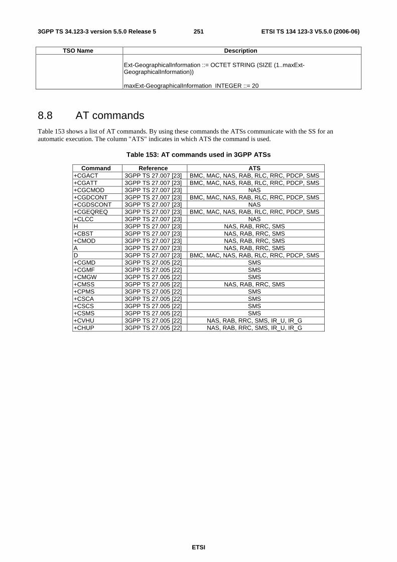
ETSI
ETSI TS 134 123-3 V5.5.0 (2006-06) 2513GPP TS 34.123-3 version 5.5.0 Release 5
TSO Name Description Ext-GeographicalInformation ::= OCTET STRING (SIZE (1..maxExt-GeographicalInformation)) maxExt-GeographicalInformation INTEGER ::= 20
8.8 AT commands Table 153 shows a list of AT commands. By using these commands the ATSs communicate with the SS for an automatic execution. The column "ATS" indicates in which ATS the command is used.
Table 153: AT commands used in 3GPP ATSs
Command Reference ATS +CGACT 3GPP TS 27.007 [23] BMC, MAC, NAS, RAB, RLC, RRC, PDCP, SMS +CGATT 3GPP TS 27.007 [23] BMC, MAC, NAS, RAB, RLC, RRC, PDCP, SMS +CGCMOD 3GPP TS 27.007 [23] NAS +CGDCONT 3GPP TS 27.007 [23] BMC, MAC, NAS, RAB, RLC, RRC, PDCP, SMS +CGDSCONT 3GPP TS 27.007 [23] NAS +CGEQREQ 3GPP TS 27.007 [23] BMC, MAC, NAS, RAB, RLC, RRC, PDCP, SMS +CLCC 3GPP TS 27.007 [23] NAS H 3GPP TS 27.007 [23] NAS, RAB, RRC, SMS +CBST 3GPP TS 27.007 [23] NAS, RAB, RRC, SMS +CMOD 3GPP TS 27.007 [23] NAS, RAB, RRC, SMS A 3GPP TS 27.007 [23] NAS, RAB, RRC, SMS D 3GPP TS 27.007 [23] BMC, MAC, NAS, RAB, RLC, RRC, PDCP, SMS +CGMD 3GPP TS 27.005 [22] SMS +CGMF 3GPP TS 27.005 [22] SMS +CMGW 3GPP TS 27.005 [22] SMS +CMSS 3GPP TS 27.005 [22] NAS, RAB, RRC, SMS +CPMS 3GPP TS 27.005 [22] SMS +CSCA 3GPP TS 27.005 [22] SMS +CSCS 3GPP TS 27.005 [22] SMS +CSMS 3GPP TS 27.005 [22] SMS +CVHU 3GPP TS 27.005 [22] NAS, RAB, RRC, SMS, IR_U, IR_G +CHUP 3GPP TS 27.005 [22] NAS, RAB, RRC, SMS, IR_U, IR_G
ETSI
ETSI TS 134 123-3 V5.5.0 (2006-06) 2523GPP TS 34.123-3 version 5.5.0 Release 5
8.8.1 AT command lists in ATSs
8.8.1.1 AT commands in IR_U ATS:
Command Syntax in TTCN Comments CBST AT+CBST=[<speed>[,<name>[,<ce>]]]<CR>
<speed>=0,7,12,14,15,16,17,39,43,47,48,49,50,51,71,75,79,80,81,82,83,84,115,116,120,121 <name>=0,1,4,5 <ce>=0,1
Select bearer service type, TS 27.007 clause 6.7
CGACT AT+CGACT=1,1<CR> AT+CGACT=0,1<CR>
PDP context activate or deactivate, TS 27.007 clause 10.1.10
CGATT AT+CGATT=1<CR> PS attach or detach, TS 27.007 clause 10.1.9
CGDSCONT AT+CGDSCONT= 1,<CR> AT+ CGDSCONT=1 , 1, "IP", 0,0,<CR>
Establish secondary PDP Context, TS 27.007 clause 10.1.2
CGEQREQ AT+CGEQREQ=1,2,64,64,,,0,320,"1E4","1E5",1,,3<CR> AT+CGEQREQ=1,3,64,64,,,0,320,"1E4","1E5",1,,<CR>
Quality of Service Profile (Requested), TS 27.007 clause 10.1.4
CHUP AT+CHUP<CR> Hang up call, TS 27.007 clause 6.5 CMOD AT+CMOD=0<CR>
AT+CMOD=1<CR> Call mode, TS 27.007 clause 6.4
CMSS AT+CMSS=000<CR> AT+CMSS=001<CR> AT+CMSS=002<CR>
Send Message from Storage, TS 27.005 clause 3.5.2
CVHU AT+CVHU=0<CR> Voice Hang up control, TS 27.007 clause 6.20
8.8.1.2 AT commands in MAC and RLC ATS:
Command Syntax in TTCN Comments CGATT AT+CGATT=1<CR>
PS attach or detach, TS 27.007 clause 10.1.9

ETSI
ETSI TS 134 123-3 V5.5.0 (2006-06) 2533GPP TS 34.123-3 version 5.5.0 Release 5
8.8.1.3 AT commands in NAS ATS:
Command Syntax in TTCN Comments CBST AT+CBST=[<speed>[,<name>[,<ce>]]]<CR>
<speed>=0,7,12,14,15,16,17,39,43,47,48,49,50,51,71,75,79,80,81,82,83,84,115,116,120,121 <name>=0,1,4,5 <ce>=0,1
Select bearer service type, TS 27.007 clause 6.7
CGACT AT+CGACT=1,1<CR> AT+CGACT=0,1<CR>
PDP context activate or deactivate, TS 27.007 clause 10.1.10
CGATT AT+CGATT=1<CR> AT+CGATT=0<CR>
PS attach or detach, TS 27.007 clause 10.1.9
CGDATA AT+CGDATA=PPP,1<CR> Enter data state, TS 27.007 clause 10.1.12
CGDCONT AT+CGDCONT=1,"IP","ABCDEF","200.1.1.80",0,0<CR> AT+CGDCONT=1,"IP","GHIJK","200.1.1.90",0,0<CR>
Define PDP Context, TS 27.007 clause 10.1.1
CGDSCONT AT+CGDSCONT= 1,<CR> AT+ CGDSCONT=1 , 1, "IP", 0,0,<CR>
Establish secondary PDP Context, TS 27.007 clause 10.1.2
CGEQMIN AT+CGEQMIN=1,3,32,32,,,1,320,"1E3","4E3",1,,<CR> AT+CGEQMIN=1,3,64,64,,,1,320,"1E3","4E3",1,,<CR> AT+CGEQMIN=1,2,32, 32, 32, 32, 1, 320, 1E4,6E8,1,,,<CR> AT+CGEQMIN=1,3,32, 32, 32, 32, 1, 320, 1E4,6E8,1,,,<CR> AT+CGEQMIN=1,2,32, 32, 32, 32, 1, 320, 1E3,6E8,1,,,<CR> AT+CGEQMIN=1,3,32, 32, 32, 32, 1, 320, 1E3,6E8,1,,,<CR> AT+CGEQMIN=1,2,64, 64, 64, 64, 1, 320, 1E3,6E8,1,,,<CR> AT+CGEQMIN=1,3,64, 64, 64, 64, 1, 320, 1E3,6E8,1,,,<CR>
Quality of Service Profile (Minimum acceptable), TS 27.007 clause 10.1.4
CGEQREQ AT+CGEQREQ=1,2,64,64,,,0,320,"1E4","1E5",1,,3<CR> AT+CGEQREQ=1,3,64,64,,,0,320,"1E4","1E5",1,,<CR> AT+CGEQREQ=1,2,64, 64, 64, 64, 0, 320, 1E4,6E8,1,,,<CR> AT+CGEQREQ=1,3,64, 64, 64, 64, 0, 320, 1E4,6E8,1,,,<CR>
Quality of Service Profile (Requested), TS 27.007 clause 10.1.4
CHUP AT+CHUP<CR> Hang up call, TS 27.007 clause 6.5
CLCC AT+CLCC<CR> List current calls, TS 27.007 clause 7.18
CMOD AT+CMOD=0<CR> AT+CMOD=1<CR>
Call mode, TS 27.007 clause 6.4
CMSS AT+CMSS=000<CR> AT+CMSS=001<CR> AT+CMSS=002<CR>
Send Message from Storage, TS 27.005 clause 3.5.2
VTS AT+VTS=0,100<CR> AT+VTS=1,50<CR> AT+VTS=2,60<CR> AT+VTS=3,40<CR> AT+VTS=4,50<CR> AT+VTS=5,60<CR> AT+VTS=6,70<CR> AT+VTS=7,80<CR> AT+VTS=8,90<CR> AT+VTS=9,100<CR> AT+VTS=#,110<CR> AT+VTS=\*,120<CR> AT+VTS=A,130<CR> AT+VTS=B,140<CR> AT+VTS=C,150<CR> AT+VTS=D,200<CR>
DTMF and tone generation, TS 27.007 clause C.2.11
CVHU AT+CVHU=0<CR> Voice Hang up control, TS 27.007 clause 6.20

ETSI
ETSI TS 134 123-3 V5.5.0 (2006-06) 2543GPP TS 34.123-3 version 5.5.0 Release 5
8.8.1.4 AT commands in RAB ATS:
Command Syntax in TTCN Comments CBST AT+CBST=[<speed>[,<name>[,<ce>]]]<CR>
<speed>=0,7,12,14,15,16,17,39,43,47,48,49,50,51,71,75,79,80,81,82,83,84,115,116,120,121 <name>=0,1,4,5 <ce>=0,1
Select bearer service type, TS 27.007 clause 6.7
CGACT AT+CGACT=1,1<CR> AT+CGACT=0,1<CR>
PDP context activate or deactivate, TS 27.007 clause 10.1.10
CGATT AT+CGATT=1<CR> PS attach or detach, TS 27.007 clause 10.1.9
CGDCONT AT+CGDCONT=1,"IP","ABCDEF","200.1.1.80",0,0<CR> AT+CGDCONT=1,"IP","GHIJK","200.1.1.90",0,0<CR>
Define PDP Context, TS 27.007 clause 10.1.1
CGDSCONT AT+CGDSCONT= 1,<CR> AT+ CGDSCONT=1 , 1, "IP", 0,0,<CR>
Establish secondary PDP Context, TS 27.007 clause 10.1.2
CGEQREQ AT+CGEQREQ=1,2,64,64,,,0,320,"1E4","1E5",1,,3<CR> AT+CGEQREQ=1,3,64,64,,,0,320,"1E4","1E5",1,,<CR>
Quality of Service Profile (Requested), TS 27.007 clause 10.1.4
CHUP AT+CHUP<CR> Hang up call, TS 27.007 clause 6.5 CMOD AT+CMOD=0<CR>
AT+CMOD=1<CR> Call mode, TS 27.007 clause 6.4
CMSS AT+CMSS=000<CR> AT+CMSS=001<CR> AT+CMSS=002<CR>
Send Message from Storage, TS 27.005 clause 3.5.2
CVHU AT+CVHU=0<CR> Voice Hang up control, TS 27.007 clause 6.20
8.8.1.5 AT commands in RRC ATS:
Command Syntax in TTCN Comments ATA ATA<CR> Answer a call, TS 27.007 clause
6.35 ATD ATD0123456902;<CR>
ATD112;<CR> ATD0123456902<CR>
Originates a call, TS 27.007 clause 6.31
ATH ATH<CR> Hang-up a single mode call, TS 27.007 clause 6.36
CBST AT+CBST=[<speed>[,<name>[,<ce>]]]<CR> <speed>=0,7,12,14,15,16,17,39,43,47,48,49,50,51,71,75,79,80,81,82,83,84,115,116,120,121 <name>=0,1,4,5 <ce>=0,1
Select bearer service type, TS 27.007 clause 6.7
CGACT AT+CGACT=1,1<CR> AT+CGACT=0,1<CR>
PDP context activate or deactivate, TS 27.007 clause 10.1.10
CGATT AT+CGATT=1<CR> PS attach or detach, TS 27.007 clause 10.1.9
CGDCONT AT+CGDCONT=1,"IP","ABCDEF","200.1.1.80",0,0<CR> AT+CGDCONT=1,"IP","GHIJK","200.1.1.90",0,0<CR>
Define PDP Context, TS 27.007 clause 10.1.1
CGDSCONT AT+CGDSCONT= 1,<CR> AT+ CGDSCONT=1 , 1, "IP", 0,0,<CR>
Establish secondary PDP Context, TS 27.007 clause 10.1.2
CGEQREQ AT+CGEQREQ=1,2,64,64,,,0,320,"1E4","1E5",1,,3<CR> AT+CGEQREQ=1,3,64,64,,,0,320,"1E4","1E5",1,,<CR>
Quality of Service Profile (Requested), TS 27.007 clause 10.1.4
CHUP AT+CHUP<CR> Hang up call, TS 27.007 clause 6.5
CMOD AT+CMOD=0<CR> AT+CMOD=1<CR>
Call mode, TS 27.007 clause 6.4
CMSS AT+CMSS=000<CR> AT+CMSS=001<CR> AT+CMSS=002<CR>
Send Message from Storage, TS 27.005 clause 3.5.2
CVHU AT+CVHU=0<CR> Voice Hang up control, TS 27.007 clause 6.20
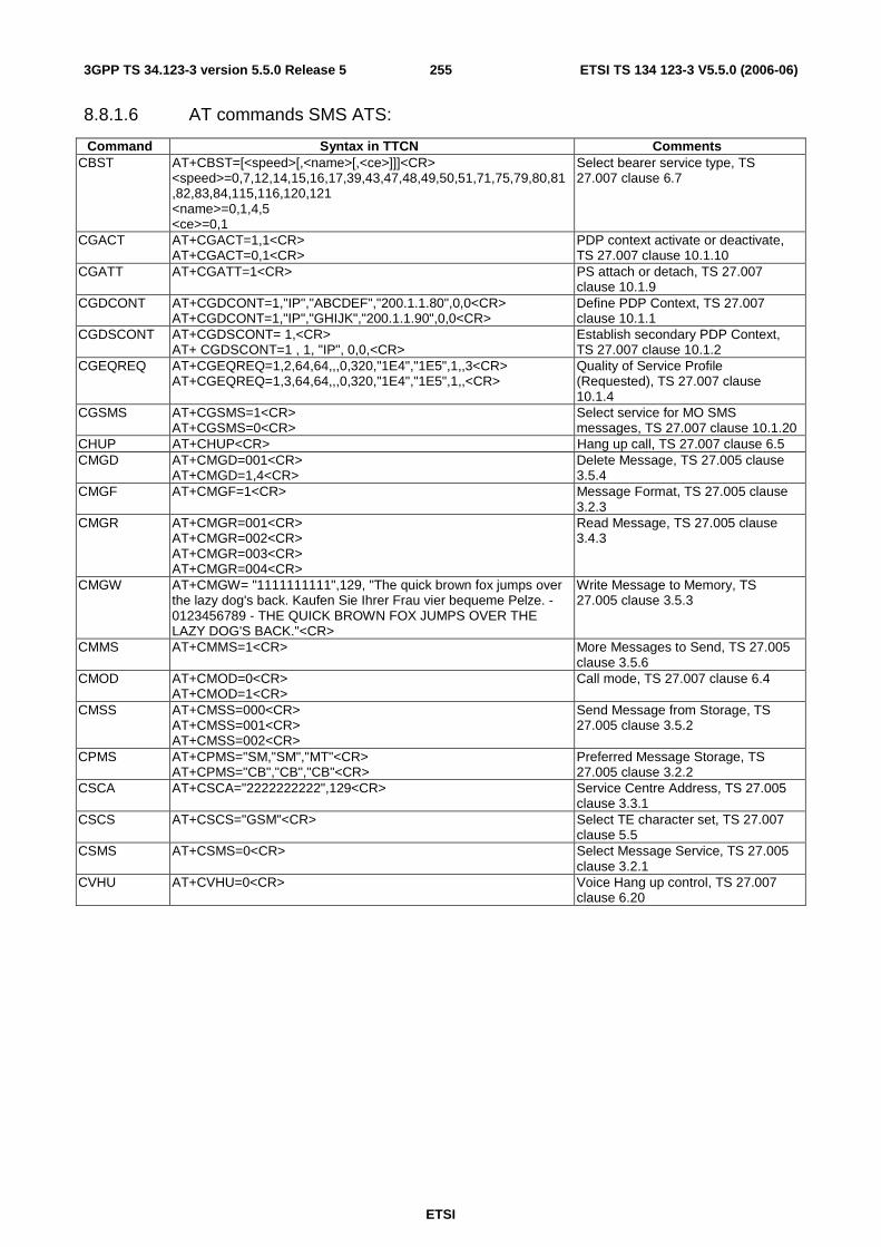
ETSI
ETSI TS 134 123-3 V5.5.0 (2006-06) 2553GPP TS 34.123-3 version 5.5.0 Release 5
8.8.1.6 AT commands SMS ATS:
Command Syntax in TTCN Comments CBST AT+CBST=[<speed>[,<name>[,<ce>]]]<CR>
<speed>=0,7,12,14,15,16,17,39,43,47,48,49,50,51,71,75,79,80,81,82,83,84,115,116,120,121 <name>=0,1,4,5 <ce>=0,1
Select bearer service type, TS 27.007 clause 6.7
CGACT AT+CGACT=1,1<CR> AT+CGACT=0,1<CR>
PDP context activate or deactivate, TS 27.007 clause 10.1.10
CGATT AT+CGATT=1<CR> PS attach or detach, TS 27.007 clause 10.1.9
CGDCONT AT+CGDCONT=1,"IP","ABCDEF","200.1.1.80",0,0<CR> AT+CGDCONT=1,"IP","GHIJK","200.1.1.90",0,0<CR>
Define PDP Context, TS 27.007 clause 10.1.1
CGDSCONT AT+CGDSCONT= 1,<CR> AT+ CGDSCONT=1 , 1, "IP", 0,0,<CR>
Establish secondary PDP Context, TS 27.007 clause 10.1.2
CGEQREQ AT+CGEQREQ=1,2,64,64,,,0,320,"1E4","1E5",1,,3<CR> AT+CGEQREQ=1,3,64,64,,,0,320,"1E4","1E5",1,,<CR>
Quality of Service Profile (Requested), TS 27.007 clause 10.1.4
CGSMS AT+CGSMS=1<CR> AT+CGSMS=0<CR>
Select service for MO SMS messages, TS 27.007 clause 10.1.20
CHUP AT+CHUP<CR> Hang up call, TS 27.007 clause 6.5 CMGD AT+CMGD=001<CR>
AT+CMGD=1,4<CR> Delete Message, TS 27.005 clause 3.5.4
CMGF AT+CMGF=1<CR> Message Format, TS 27.005 clause 3.2.3
CMGR AT+CMGR=001<CR> AT+CMGR=002<CR> AT+CMGR=003<CR> AT+CMGR=004<CR>
Read Message, TS 27.005 clause 3.4.3
CMGW AT+CMGW= "1111111111",129, "The quick brown fox jumps over the lazy dog's back. Kaufen Sie Ihrer Frau vier bequeme Pelze. - 0123456789 - THE QUICK BROWN FOX JUMPS OVER THE LAZY DOG'S BACK."<CR>
Write Message to Memory, TS 27.005 clause 3.5.3
CMMS AT+CMMS=1<CR> More Messages to Send, TS 27.005 clause 3.5.6
CMOD AT+CMOD=0<CR> AT+CMOD=1<CR>
Call mode, TS 27.007 clause 6.4
CMSS AT+CMSS=000<CR> AT+CMSS=001<CR> AT+CMSS=002<CR>
Send Message from Storage, TS 27.005 clause 3.5.2
CPMS AT+CPMS="SM,"SM","MT"<CR> AT+CPMS="CB","CB","CB"<CR>
Preferred Message Storage, TS 27.005 clause 3.2.2
CSCA AT+CSCA="2222222222",129<CR> Service Centre Address, TS 27.005 clause 3.3.1
CSCS AT+CSCS="GSM"<CR> Select TE character set, TS 27.007 clause 5.5
CSMS AT+CSMS=0<CR> Select Message Service, TS 27.005 clause 3.2.1
CVHU AT+CVHU=0<CR> Voice Hang up control, TS 27.007 clause 6.20

ETSI
ETSI TS 134 123-3 V5.5.0 (2006-06) 2563GPP TS 34.123-3 version 5.5.0 Release 5
8.8.1.7 AT commands in HSDPA ATS (Rel-5 or later):
Command Syntax in TTCN Comments CGEQREQ AT+CGEQREQ=[<cid> [,<Traffic class> [,<Maximum bitrate UL>
[,<Maximum bitrate DL> [,<Guaranteed bitrate UL> [,<Guaranteed bitrate DL> [,<Delivery order> [,<Maximum SDU size> [,<SDU error ratio> [,<Residual bit error ratio> [,<Delivery of erroneous SDUs> [,<Transfer delay> [,<Traffic handling priority> ]]]]]]]]]]]]] <CR> <cid> =1 <Traffic class> =2, 3 <Maximum bitrate UL> =64, 384 <Maximum bitrate DL> =896, 1216, 1792, 3648, 7360, 10200, 14300 <Guaranteed bitrate UL> Not used <Guaranteed bitrate DL> Not used <Delivery order> =0 <Maximum SDU size> =320, 640 <SDU error ratio> = '1E4' <Residual bit error ratio> ='1E5' <Delivery of erroneous SDUs> =1 <Transfer delay> Not used <Traffic handling priority> =3
Quality of Service Profile (Requested), TS 27.007 clause 10.1.4
8.8.2 AT Command Handling in TTCN
8.8.2.1 AT Command Interface
The AT Command Interface resides between the UE and the System Simulator (SS). The implementation of AT commands in the UE is optional[3]. It is agreed, however, that it is the responsibility of the SS - not the ATS - to map AT commands onto appropriate MMI commands. This means that the ATSs issue AT commands which have to be mapped appropriately and forwarded to the UE, and vice versa.
The ATSs have been implemented in such a way that AT commands are to be answered immediately. This means that the TTCN expects the answers right away and progresses only afterwards. As a consequence only positive AT responses are assumed.
There is only one exception from the rule of immediate answering: the CGACT command. For this command the TTCN does not expect an immediate AT response. Once the CGACT command has been issued a subsequent UE behaviour is expected. The AT response is issued by the UE only after execution of the AT command, and it will only then be accounted for by the ATSs.
8.8.2.2 AT Command Dialogues
In some cases AT commands trigger a dialogue between the AT command interface and the UE. An example used in the SMS ATS is the CMGW command.
EXAMPLE: AT+CMGW="9501231234" (write message) > This is the message body^Z +CMGW: 7 (index number in storage returned) OK
A special character (^Z) marks the end of the dialogue.
The ATSs generate information to be sent to the UE as one block. If the command mapping function cannot proceed with the dialogue that way, it has to divide the received block into the appropriate pieces prior to forwarding them.
8.8.2.3 AT Response Types
The term 'response type' shall allow a distinction between different types of contents to answer upon an AT command issued by the TTCN.
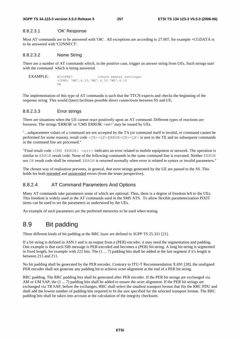
ETSI
ETSI TS 134 123-3 V5.5.0 (2006-06) 2573GPP TS 34.123-3 version 5.5.0 Release 5
8.8.2.3.1 'OK' Response
Most AT commands are to be answered with 'OK'. All exceptions are according to 27.007, for example +CGDATA is to be answered with 'CONNECT'.
8.8.2.3.2 Name String
There are a number of AT commands which, in the positive case, trigger an answer string from UEs. Such strings start with the command which is being answered.
EXAMPLE: AT+CPMS? (check memory settings) +CPMS: "ME",4,10,"ME",4,10,"ME",4,10 OK
The implementation of this type of AT commands is such that the TTCN expects and checks the beginning of the response string. This would (later) facilitate possible direct connections between SS and UE.
8.8.2.3.3 Error strings
There are situations when the UE cannot react positively upon an AT command. Different types of reactions are foreseen. The strings 'ERROR' or 'CMS ERROR: <err>' may be issued by UEs.
"...subparameter values of a command are not accepted by the TA (or command itself is invalid, or command cannot be performed for some reason), result code <CR><LF>ERROR<CR><LF> is sent to the TE and no subsequent commands in the command line are processed."
"Final result code +CMS ERROR: <err> indicates an error related to mobile equipment or network. The operation is similar to ERROR result code. None of the following commands in the same command line is executed. Neither ERROR nor OK result code shall be returned. ERROR is returned normally when error is related to syntax or invalid parameters."
The chosen way of realisation prevents, in general, that error strings generated by the UE are passed to the SS. This holds for both intended and unintended errors (from the tester perspective).
8.8.2.4 AT Command Parameters And Options
Many AT commands take parameters some of which are optional. Thus, there is a degree of freedom left to the UEs. This freedom is widely used in the AT commands used in the SMS ATS. To allow flexible parameterization PIXIT items can be used to set the parameters as understood by the UEs.
An example of such parameters are the preferred memories to be used when testing.
8.9 Bit padding Three different kinds of bit padding at the RRC layer are defined in 3GPP TS 25.331 [21].
If a bit string is defined in ASN.1 and is an output from a (PER) encoder, it may need the segmentation and padding. One example is that each SIB message is PER-encoded and becomes a (PER) bit-string. A long bit-string is segmented in fixed length, for example with 222 bits. The (1 ... 7) padding bits shall be added at the last segment if it's length is between 215 and 211.
No bit padding shall be generated by the PER encoder. Contrary to ITU-T Recommendation X.691 [28], the unaligned PER encoder shall not generate any padding bit to achieve octet alignment at the end of a PER bit string.
RRC padding. The RRC padding bits shall be generated after PER encoder. If the PER bit strings are exchanged via AM or UM SAP, the (1 ... 7) padding bits shall be added to ensure the octet alignment. If the PER bit strings are exchanged via TR SAP, before the exchanges, RRC shall select the smallest transport format that fits the RRC PDU and shall add the lowest number of padding bits required to fit the size specified for the selected transport format. The RRC padding bits shall be taken into account at the calculation of the integrity checksum.
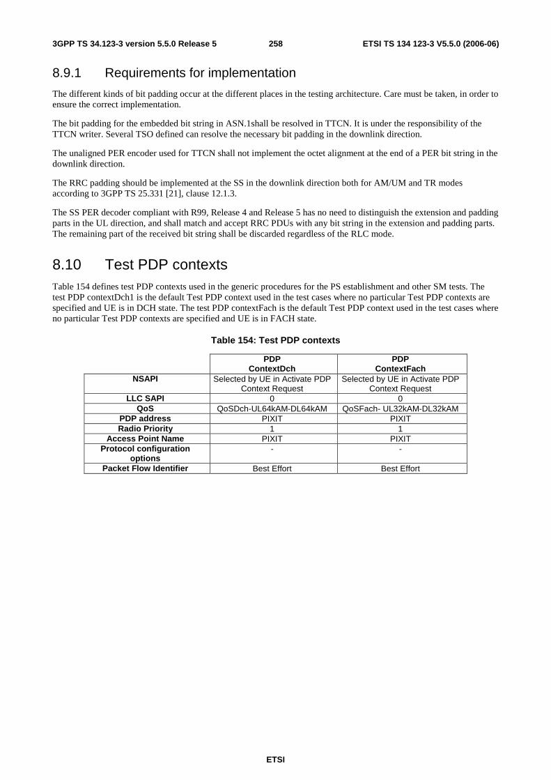
ETSI
ETSI TS 134 123-3 V5.5.0 (2006-06) 2583GPP TS 34.123-3 version 5.5.0 Release 5
8.9.1 Requirements for implementation
The different kinds of bit padding occur at the different places in the testing architecture. Care must be taken, in order to ensure the correct implementation.
The bit padding for the embedded bit string in ASN.1shall be resolved in TTCN. It is under the responsibility of the TTCN writer. Several TSO defined can resolve the necessary bit padding in the downlink direction.
The unaligned PER encoder used for TTCN shall not implement the octet alignment at the end of a PER bit string in the downlink direction.
The RRC padding should be implemented at the SS in the downlink direction both for AM/UM and TR modes according to 3GPP TS 25.331 [21], clause 12.1.3.
The SS PER decoder compliant with R99, Release 4 and Release 5 has no need to distinguish the extension and padding parts in the UL direction, and shall match and accept RRC PDUs with any bit string in the extension and padding parts. The remaining part of the received bit string shall be discarded regardless of the RLC mode.
8.10 Test PDP contexts Table 154 defines test PDP contexts used in the generic procedures for the PS establishment and other SM tests. The test PDP contextDch1 is the default Test PDP context used in the test cases where no particular Test PDP contexts are specified and UE is in DCH state. The test PDP contextFach is the default Test PDP context used in the test cases where no particular Test PDP contexts are specified and UE is in FACH state.
Table 154: Test PDP contexts
PDP ContextDch
PDP ContextFach
NSAPI Selected by UE in Activate PDP Context Request
Selected by UE in Activate PDP Context Request
LLC SAPI 0 0 QoS QoSDch-UL64kAM-DL64kAM QoSFach- UL32kAM-DL32kAM
PDP address PIXIT PIXIT Radio Priority 1 1
Access Point Name PIXIT PIXIT Protocol configuration
options - -
Packet Flow Identifier Best Effort Best Effort
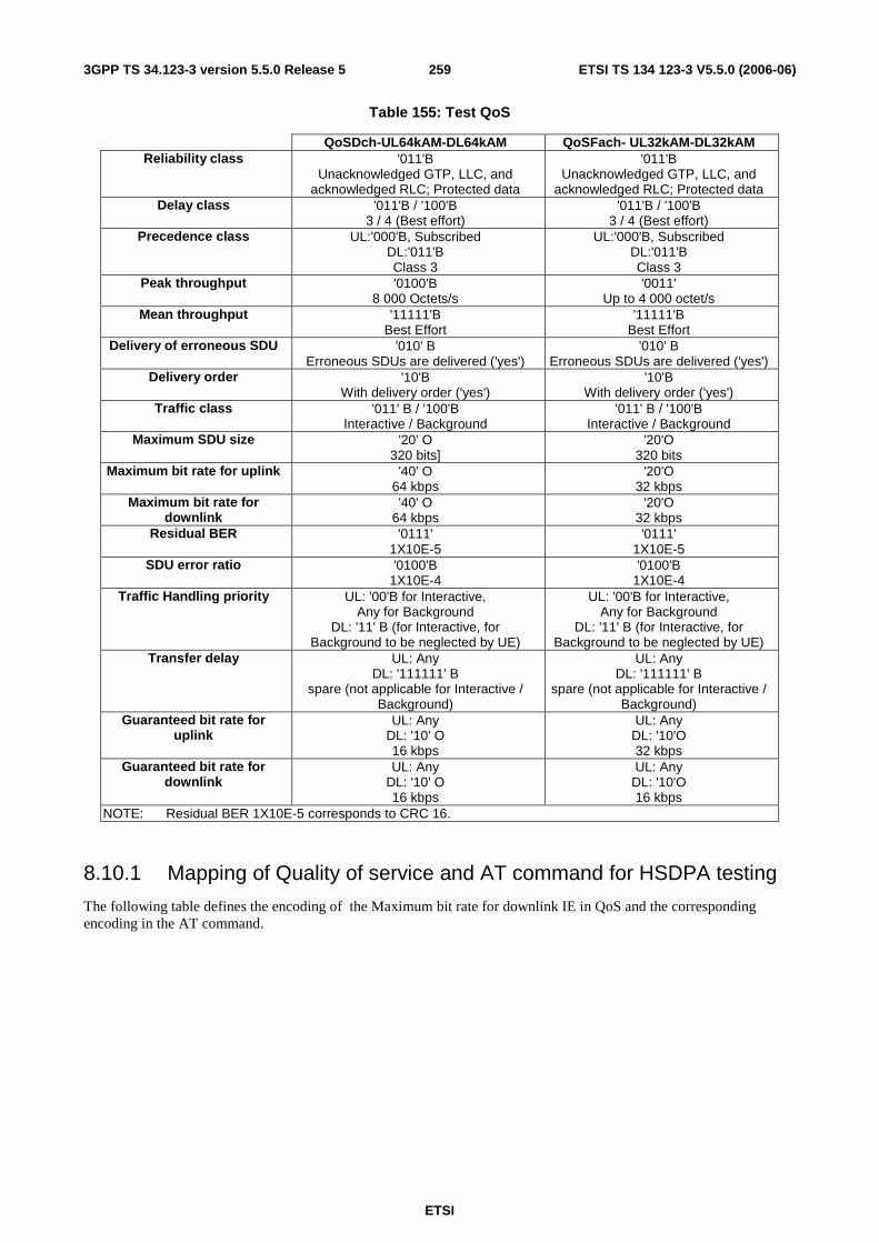
ETSI
ETSI TS 134 123-3 V5.5.0 (2006-06) 2593GPP TS 34.123-3 version 5.5.0 Release 5
Table 155: Test QoS
QoSDch-UL64kAM-DL64kAM QoSFach- UL32kAM-DL32kAM Reliability class '011'B
Unacknowledged GTP, LLC, and acknowledged RLC; Protected data
'011'B Unacknowledged GTP, LLC, and
acknowledged RLC; Protected data Delay class '011'B / '100'B
3 / 4 (Best effort) '011'B / '100'B
3 / 4 (Best effort) Precedence class UL:'000'B, Subscribed
DL:'011'B Class 3
UL:'000'B, Subscribed DL:'011'B Class 3
Peak throughput '0100'B 8 000 Octets/s
'0011' Up to 4 000 octet/s
Mean throughput '11111'B Best Effort
'11111'B Best Effort
Delivery of erroneous SDU '010' B Erroneous SDUs are delivered ('yes')
'010' B Erroneous SDUs are delivered ('yes')
Delivery order '10'B With delivery order ('yes')
'10'B With delivery order ('yes')
Traffic class '011' B / '100'B Interactive / Background
'011' B / '100'B Interactive / Background
Maximum SDU size '20' O 320 bits]
'20'O 320 bits
Maximum bit rate for uplink '40' O 64 kbps
'20'O 32 kbps
Maximum bit rate for downlink
'40' O 64 kbps
'20'O 32 kbps
Residual BER '0111' 1X10E-5
'0111' 1X10E-5
SDU error ratio '0100'B 1X10E-4
'0100'B 1X10E-4
Traffic Handling priority UL: '00'B for Interactive, Any for Background
DL: '11' B (for Interactive, for Background to be neglected by UE)
UL: '00'B for Interactive, Any for Background
DL: '11' B (for Interactive, for Background to be neglected by UE)
Transfer delay UL: Any DL: '111111' B
spare (not applicable for Interactive / Background)
UL: Any DL: '111111' B
spare (not applicable for Interactive / Background)
Guaranteed bit rate for uplink
UL: Any DL: '10' O 16 kbps
UL: Any DL: '10'O 32 kbps
Guaranteed bit rate for downlink
UL: Any DL: '10' O 16 kbps
UL: Any DL: '10'O 16 kbps
NOTE: Residual BER 1X10E-5 corresponds to CRC 16.
8.10.1 Mapping of Quality of service and AT command for HSDPA testing
The following table defines the encoding of the Maximum bit rate for downlink IE in QoS and the corresponding encoding in the AT command.

ETSI
ETSI TS 134 123-3 V5.5.0 (2006-06) 2603GPP TS 34.123-3 version 5.5.0 Release 5
Table 156: Test QoS in HSDPA test cases (Rel-5 or later)
UE HSDPA Category
Max bit rate of each category
(Mbits)
Max bit rate of each category
(kbits)
Max bit rate for downlink IE of QoS
(Octetstring)
Encoding AT command for Max bit rate of QoS
(IA5string) 1 and 2 1.2 1228.8 8A 1216 3, 4, 12 1.8 1843.2 93 1792 5,6 3.6 3686.4 B0 3648 7.8 7.2 7372.8 EA 7360 9 10 10240 FE (octet 9)
10 (octet 15) 10200
10 14 14336 FE (octet 9) 39 (octet 15)
14300
11 0.9 921.6 85 896
8.11 DCH-DSCH Configurations 1. Configure PDSCH physical channel
CPHY_RL_Setup_REQ( physicalChannelIdentity, pDSCHInfo) -- set up the scrambling code and transmission power level for the PDSCH identified by PhysicalChannelIdentity, and establishes the mapping between the spreading factor(and channelization codes) used for the PDSCH and TFCI(field2) transmitted in associated PDCH
2. Configure DSCH transport channels
CPHY_TrCH_Config_REQ( physicalChannelIdentity, dlconnectedTrCHList, dlTFCS) -- set up TFS for each of DSCH's carried by the PDSCH defined in step 1 and TFCS (will be presented in TFCI(field2) of PDCH configured in step 5) for the CCTrCH consisting of these DSCH's
3. Configure MAC entity for DSCH
CMAC_Config_REQ( physicalChannelIdentity, uE_Info, dlconnectedTrCHList, dlTFCS) -- set up TFS, DSCH-RNTI and TFCS (which will be presented in TFCI(field2) of PDCH configured in step 5) for DSCH's, and map logical channel to DSCH transport channel
4. Configure RLC entity for DTCHs
CRLC_Config_REQ( physicalChannelIdentity, rBInfo) -- set up RLC entity on top of DTCH logical channel which is mapped onto DSCH
5. Configure DPCH physical channel
CPHY_RL_Setup_REQ( physicalChannelIdentity, dPCHInfo)
6. Configure DCH transport channels
CPHY_TrCH_Config_REQ( physicalChannelIdentity, dlconnectedTrCHList, dlTFCS) -- set up TFS for each DCH carried by the DPCH defined in step 5 and TFCS (TFCI(field1 and field2)) for the CCTrCH consisting of all DCH's mapped on the DPCH.
7. Configure MAC entity for DCH
CMAC_Config_REQ( physicalChannelIdentity,
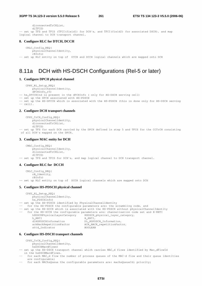
ETSI
ETSI TS 134 123-3 V5.5.0 (2006-06) 2613GPP TS 34.123-3 version 5.5.0 Release 5
dlconnectedTrCHList, dlTFCS) -- set up TFS and TFCS (TFCI(field1) for DCH's, and TFCI(field2) for associated DSCH), and map logical channel to DCH transport channel.
8. Configure RLC for DTCH, DCCH
CRLC_Config_REQ( physicalChannelIdentity, rBInfo) -- set up RLC entity on top of DTCH and DCCH logical channels which are mapped onto DCH
8.11a DCH with HS-DSCH Configurations (Rel-5 or later) 1. Configure DPCH physical channel
CPHY_RL_Setup_REQ( physicalChannelIdentity, dPCHInfo_r5) -- hs_DPCCHInd is present in the dPCHInfo ( only for HS-DSCH serving cell) -- set up the DPCH associated with HS-PDSCH -- set up the HS-DPCCH which is associated with the HS-PDSCH (this is done only for HS-DSCH serving -- cell).
2. Configure DCH transport channels
CPHY_TrCH_Config_REQ( physicalChannelIdentity, dlconnectedTrCHList, dlTFCS) -- set up TFS for each DCH carried by the DPCH defined in step 5 and TFCS for the CCTrCH consisting of all DCH's mapped on the DPCH.
3. Configure MAC entity for DCH
CMAC_Config_REQ( physicalChannelIdentity, dlconnectedTrCHList, dlTFCS) -- set up TFS and TFCS for DCH's, and map logical channel to DCH transport channel.
4. Configure RLC for DCCH
CRLC_Config_REQ( rB_Identity, rBInfo) -- set up RLC entity on top of DCCH logical channels which are mapped onto DCH
5. Configure HS-PDSCH physical channel
CPHY_RL_Setup_REQ( physicalChannelIdentity, hs_PDSCHInfo) -- set up the HS-PDSCH identified by PhysicalChannelIdentity -- for the HS-PDSCH the configurable parameters are: the scrambling code, and -- set up the HS-SCCH which is associated with the HS-PDSCH without physicalChannelIdentity -- for the HS-SCCH the configurable parameters are: channelisation code set and H-RNTI hSDSCHPhysicalLayerCategory HSDSCH_physical_layer_category, h_RNTI H_RNTI, dlHSPDSCHInformation DL_HSPDSCH_Information, ackNackRepetitionFactor ACK_NACK_repetitionFactor, sttd_Indicator BOOLEAN
6. Configure HS-DSCH transport channels
CPHY_TrCH_Config_REQ( physicalChannelIdentity, hsDSCHMacdFlows) -- set up the HS-DSCH transport channel which carries MAC_d flows identified by Mac_dFlowId in the hsDSCHMacdFlows. -- for each MAC_d flow the number of process queues of the MAC-d flow and their queue identities are configurable; -- for each MAChsQueue the configurable parameters are: machsQueueId; priority;
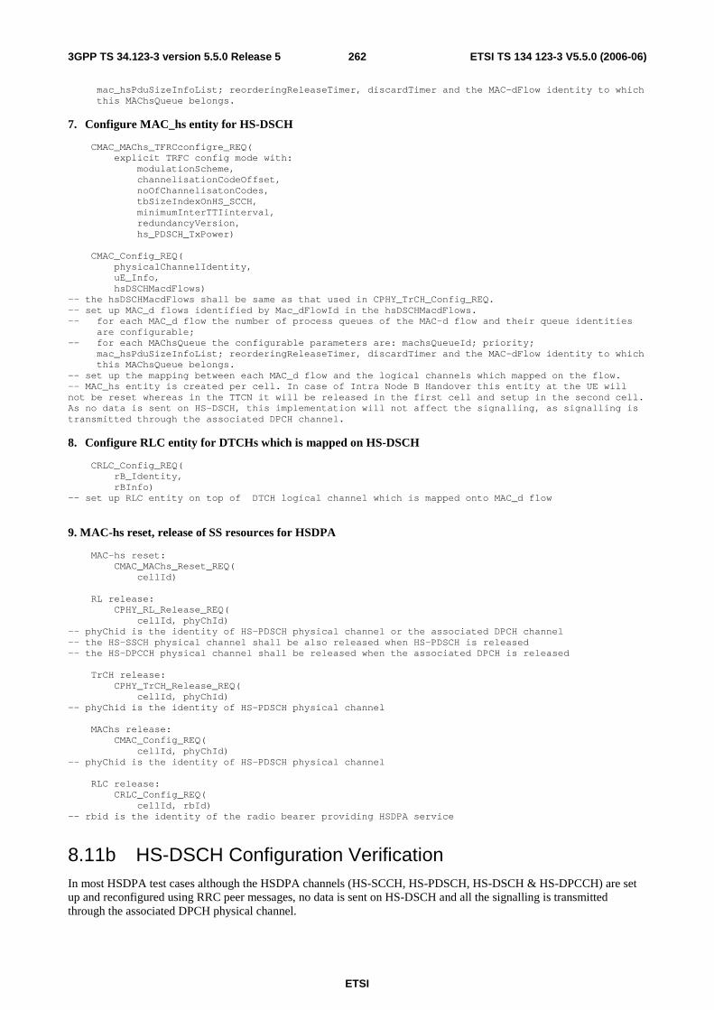
ETSI
ETSI TS 134 123-3 V5.5.0 (2006-06) 2623GPP TS 34.123-3 version 5.5.0 Release 5
mac_hsPduSizeInfoList; reorderingReleaseTimer, discardTimer and the MAC-dFlow identity to which this MAChsQueue belongs.
7. Configure MAC_hs entity for HS-DSCH
CMAC_MAChs_TFRCconfigre_REQ( explicit TRFC config mode with: modulationScheme, channelisationCodeOffset, noOfChannelisatonCodes, tbSizeIndexOnHS_SCCH, minimumInterTTIinterval, redundancyVersion, hs_PDSCH_TxPower) CMAC_Config_REQ( physicalChannelIdentity, uE_Info, hsDSCHMacdFlows) -- the hsDSCHMacdFlows shall be same as that used in CPHY_TrCH_Config_REQ. -- set up MAC_d flows identified by Mac_dFlowId in the hsDSCHMacdFlows. -- for each MAC_d flow the number of process queues of the MAC-d flow and their queue identities are configurable; -- for each MAChsQueue the configurable parameters are: machsQueueId; priority; mac_hsPduSizeInfoList; reorderingReleaseTimer, discardTimer and the MAC-dFlow identity to which this MAChsQueue belongs. -- set up the mapping between each MAC_d flow and the logical channels which mapped on the flow. -- MAC_hs entity is created per cell. In case of Intra Node B Handover this entity at the UE will not be reset whereas in the TTCN it will be released in the first cell and setup in the second cell. As no data is sent on HS-DSCH, this implementation will not affect the signalling, as signalling is transmitted through the associated DPCH channel.
8. Configure RLC entity for DTCHs which is mapped on HS-DSCH
CRLC_Config_REQ( rB_Identity, rBInfo) -- set up RLC entity on top of DTCH logical channel which is mapped onto MAC_d flow
9. MAC-hs reset, release of SS resources for HSDPA
MAC-hs reset: CMAC_MAChs_Reset_REQ( cellId) RL release: CPHY_RL_Release_REQ( cellId, phyChId) -- phyChid is the identity of HS-PDSCH physical channel or the associated DPCH channel -- the HS-SSCH physical channel shall be also released when HS-PDSCH is released -- the HS-DPCCH physical channel shall be released when the associated DPCH is released TrCH release: CPHY_TrCH_Release_REQ( cellId, phyChId) -- phyChid is the identity of HS-PDSCH physical channel MAChs release: CMAC_Config_REQ( cellId, phyChId) -- phyChid is the identity of HS-PDSCH physical channel RLC release: CRLC_Config_REQ( cellId, rbId) -- rbid is the identity of the radio bearer providing HSDPA service
8.11b HS-DSCH Configuration Verification In most HSDPA test cases although the HSDPA channels (HS-SCCH, HS-PDSCH, HS-DSCH & HS-DPCCH) are set up and reconfigured using RRC peer messages, no data is sent on HS-DSCH and all the signalling is transmitted through the associated DPCH physical channel.

ETSI
ETSI TS 134 123-3 V5.5.0 (2006-06) 2633GPP TS 34.123-3 version 5.5.0 Release 5
In order to ensure that the HS-DPCCH channel has been configured, the SS shall, upon request, forward one CQI report to the TTCN.
8.12 Pre- and postambles for GERAN to UTRAN tests
8.12.1 Preamble for GERAN to UTRAN tests
Before running inter-RAT test cases, radio conditions should be such that the mobile has to select the cell of the intended original RAT. The following steps should be used before running GERAN to UTRAN test cases.
1. UTRAN cell is powered OFF. The default radio conditions for a suitable GERAN cell are used for the serving cell, as defined in 3GPP TS 34.108 [3], clause 6.1.7. This step is performed while the UE is still switched OFF.
2. UE is switched ON and performs registration and attach.
3. The UTRAN cell is powered ON with an RF level such that the cell is a suitable neighbour cell, using the RF conditions defined in 3GPP TS 34.108 [3], clause 6.1.5, so that the UE will not re-select the UTRAN cell.
8.12.2 Postamble for GERAN to UTRAN tests
The following procedure is used after inter-RAT handover or cell change order test cases in case the test needs to be performed multiple times in a loop.
8.12.2.1 GERAN to UTRAN handover in CS
The test cases are defined in 3GPP TS 51.010-1 [26], clause 60.

ETSI
ETSI TS 134 123-3 V5.5.0 (2006-06) 2643GPP TS 34.123-3 version 5.5.0 Release 5
Expected sequence
Step Direction Message Comments UE SS
1 <-- SECURITY MODE COMMAND Integrity protection is activated. UTRAN security keys in CS domain derived from GERAN
2 --> SECURITY MODE COMPLETE 3 <-- UTRAN MOBILITY INFORMATION RRC 4 --> UTRAN MOBILITY INFORMATION CONFIRM RRC 5 --> ROUTING AREA UPDATE REQUEST GMM - Update type = 'RA
updating'. Not performed by CS only mobile.
5a <-- SECURITY MODE COMMAND Integrity protection is activated. UTRAN security keys in PS domain derived from GERAN
5b --> SECURITY MODE COMPLETE
6 <-- ROUTING AREA UPDATE ACCEPT GMM - P-TMSI is included 7 --> ROUTING AREA UPDATE COMPLETE 8 The call is terminated. SS
releases the RRC connection. 9 --> RRC CONNECTION REQUEST RRC - establishment cause =
'registration' 10 <-- RRC CONNECTION SETUP RRC 11 --> RRC CONNECTION SETUP COMPLETE RRC 12 --> ROUTING AREA UPDATE REQUEST CS/PS mobiles: GMM - Update
type" = 'combined RA/LA updating' or 'combined RA/LA updating with ISMI Attach' Note: CS only mobiles will perform a normal LAU
13 <-- SECURITY MODE COMMAND Integrity protection is activated. 14 --> SECURITY MODE COMPLETE 15 <-- ROUTING AREA UPDATE ACCEPT P-TMSI is included 16 --> ROUTING AREA UPDATE COMPLETE 17 The SS releases the RRC
connection. 18 UE is powered OFF
Specific message contents
UTRAN MOBILITY INFORMATION message:
Use the same message sub-type found in TS 34.108, clause 9, with the following exceptions:
Information Element Value/remark CN information info - PLMN identity Not present - CN domain related information - CN domain identity PS - CN domain specific NAS system information - GSM-MAP NAS system information 00 00H - CN domain specific DRX cycle length coefficient 7
SECURITY MODE COMMAND message:
Use the same message sub-type found in TS 34.108, clause 9, with the following exceptions:
Information Element Value/remark Ciphering mode info Not present
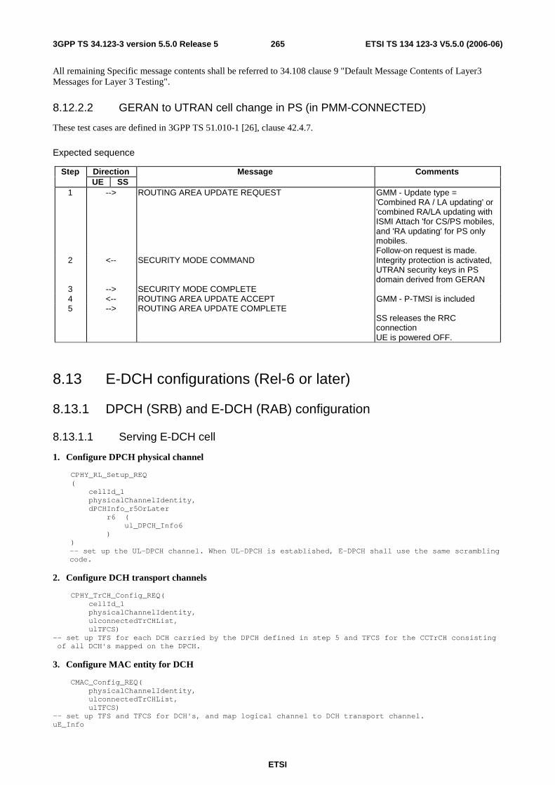
ETSI
ETSI TS 134 123-3 V5.5.0 (2006-06) 2653GPP TS 34.123-3 version 5.5.0 Release 5
All remaining Specific message contents shall be referred to 34.108 clause 9 "Default Message Contents of Layer3 Messages for Layer 3 Testing".
8.12.2.2 GERAN to UTRAN cell change in PS (in PMM-CONNECTED)
These test cases are defined in 3GPP TS 51.010-1 [26], clause 42.4.7.
Expected sequence
Step Direction Message Comments UE SS
1 --> ROUTING AREA UPDATE REQUEST GMM - Update type = 'Combined RA / LA updating' or 'combined RA/LA updating with ISMI Attach 'for CS/PS mobiles, and 'RA updating' for PS only mobiles. Follow-on request is made.
2 <-- SECURITY MODE COMMAND Integrity protection is activated, UTRAN security keys in PS domain derived from GERAN
3 --> SECURITY MODE COMPLETE 4 <-- ROUTING AREA UPDATE ACCEPT GMM - P-TMSI is included 5 --> ROUTING AREA UPDATE COMPLETE SS releases the RRC
connection UE is powered OFF.
8.13 E-DCH configurations (Rel-6 or later)
8.13.1 DPCH (SRB) and E-DCH (RAB) configuration
8.13.1.1 Serving E-DCH cell
1. Configure DPCH physical channel
CPHY_RL_Setup_REQ ( cellId_1 physicalChannelIdentity, dPCHInfo_r5OrLater r6 ( ul_DPCH_Info6 ) )
-- set up the UL-DPCH channel. When UL-DPCH is established, E-DPCH shall use the same scrambling code.
2. Configure DCH transport channels
CPHY_TrCH_Config_REQ( cellId_1 physicalChannelIdentity, ulconnectedTrCHList, ulTFCS) -- set up TFS for each DCH carried by the DPCH defined in step 5 and TFCS for the CCTrCH consisting of all DCH's mapped on the DPCH.
3. Configure MAC entity for DCH
CMAC_Config_REQ( physicalChannelIdentity, ulconnectedTrCHList, ulTFCS) -- set up TFS and TFCS for DCH's, and map logical channel to DCH transport channel. uE_Info
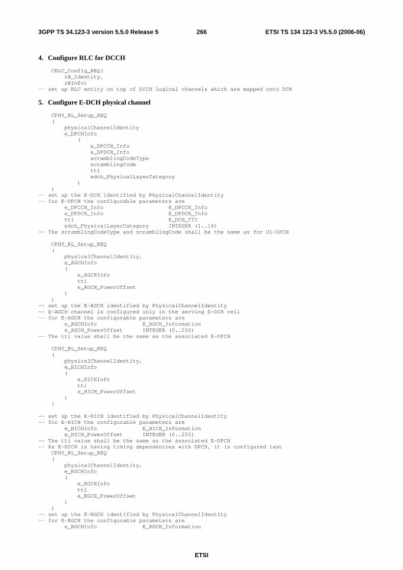
ETSI
ETSI TS 134 123-3 V5.5.0 (2006-06) 2663GPP TS 34.123-3 version 5.5.0 Release 5
4. Configure RLC for DCCH
CRLC_Config_REQ( rB_Identity, rBInfo) -- set up RLC entity on top of DCCH logical channels which are mapped onto DCH
5. Configure E-DCH physical channel
CPHY_RL_Setup_REQ ( physicalChannelIdentity e_DPCHInfo ( e_DPCCH_Info e_DPDCH_Info scramblingCodeType scramblingCode tti edch_PhysicalLayerCategory ) ) -- set up the E-DCH identified by PhysicalChannelIdentity -- for E-DPCH the configurable parameters are e_DPCCH_Info E_DPCCH_Info e_DPDCH_Info E_DPDCH_Info tti E_DCH_TTI edch_PhysicalLayerCategory INTEGER (1..16) -- The scramblingCodeType and scramblingCode shall be the same as for Ul-DPCH CPHY_RL_Setup_REQ ( physicalChannelIdentity, e_AGCHInfo ( e_AGCHInfo tti e_AGCH_PowerOffset ) ) -- set up the E-AGCH identified by PhysicalChannelIdentity -- E-AGCH channel is configured only in the serving E-DCH cell -- for E-AGCH the configurable parameters are e_AGCHInfo E_AGCH_Information e_AGCH_PowerOffset INTEGER (0..255) -- The tti value shall be the same as the associated E-DPCH CPHY_RL_Setup_REQ ( physicalChannelIdentity, e_HICHInfo ( e_HICHInfo tti e_HICH_PowerOffset ) } -- set up the E-HICH identified by PhysicalChannelIdentity -- for E-HICH the configurable parameters are e_HICHInfo E_HICH_Information e_HICH_PowerOffset INTEGER (0..255) -- The tti value shall be the same as the associated E-DPCH -- As E-HICH is having timing dependencies with DPCH, it is configured last CPHY_RL_Setup_REQ ( physicalChannelIdentity, e_RGCHInfo ( e_RGCHInfo tti e_RGCH_PowerOffset ) ) -- set up the E-RGCH identified by PhysicalChannelIdentity -- for E-RGCH the configurable parameters are e_RGCHInfo E_RGCH_Information
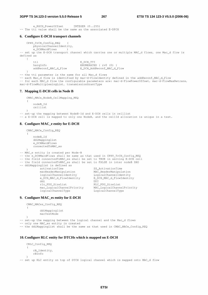
ETSI
ETSI TS 134 123-3 V5.5.0 (2006-06) 2673GPP TS 34.123-3 version 5.5.0 Release 5
e_RGCH_PowerOffset INTEGER (0..255) -- The tti value shall be the same as the associated E-DPCH
6. Configure E-DCH transport channels
CPHY_TrCH_Config_REQ ( physicalChannelIdentity, e_DCHMacdFlows ) -- set up the E-DCH transport channel which carries one or multiple MAC_d flows, one Mac_d flow is defined as { tti E_DCH_TTI harqInfo ENUMERATED { rv0 (0) } addReconf_MAC_d_Flow E_DCH_AddReconf_MAC_d_Flow } -- the tti parameter is the same for all Mac_d flows -- each Mac_d flow is identified by mac-d-FlowIdentity defined in the addReconf_MAC_d_Flow -- for each MAC_d flow the configurable parameters are: mac-d-FlowPowerOffset, mac-d-FlowMaxRetrans, mac-d-FlowMultiplexingList, transmissionGrantType
7. Mapping E-DCH cells in Node B
CMAC_MACe_NodeB_CellMapping_REQ ( nodeB_Id celllist ) -- set-up the mapping between NodeB-Id and E-DCH cells in celllist -- a E-DCH cell is mapped to only one NodeB, and the cellId allocation is unique in a test.
8. Configure MAC_e entity for E-DCH
CMAC_MACe_Config_REQ ( nodeB_Id ddiMappinglist e_DCHMacdFlows connectedToMAC_es ) -- MAC_e entity is created per Node-B -- the e_DCHMacdFlows shall be same as that used in CPHY_TrCH_Config_REQ -- the field connectedToMAC_es shall be set to TRUE in serving E-DCH cell -- the field connectedToMAC_es shall be set to FALSE in inter nodeB SHO -- ddiMappinglist is defined as activationTime SS_ActivationTime macHeaderManipulation MAC_HeaderManipulation logicalChannelIdentity LogicalChannelIdentity e_DCH_MAC_d_FlowIdentity E_DCH_MAC_d_FlowIdentity ddi DDI rlc_PDU_SizeList RLC_PDU_SizeList mac_LogicalChannelPriority MAC_LogicalChannelPriority logicalChannelType LogicalChannelType
9. Configure MAC_es entity for E-DCH
CMAC_MACes_Config_REQ ( ddiMappinglist macTestMode ) -- set-up the mapping between the logical channel and the Mac_d flows -- only one MAC_es entity is created -- the ddiMappinglist shall be the same as that used in CMAC_MACe_Config_REQ
10. Configure RLC entity for DTCHs which is mapped on E-DCH
CRLC_Config_REQ ( rB_Identity, rBInfo ) -- set up RLC entity on top of DTCH logical channel which is mapped onto MAC_d flow

ETSI
ETSI TS 134 123-3 V5.5.0 (2006-06) 2683GPP TS 34.123-3 version 5.5.0 Release 5
8.13.1.2 SHO - addition of E-DCH RL in a serving RL cell (intra node B)
1. Configure E-DCH physical channel
-- E-DPCH is not configured: the cell is under the control of the same nodeB as the initial RL. -- E-AGCH channel is not configured, it is configured only in the serving E-DCH cell CPHY_RL_Setup_REQ ( physicalChannelIdentity, e_HICHInfo ( e_HICHInfo tti e_HICH_PowerOffset ) } -- set up the E-HICH identified by PhysicalChannelIdentity -- for E-HICH the configurable parameters are e_HICHInfo E_HICH_Information e_HICH_PowerOffset INTEGER (0..255) -- The tti value shall be the same as the associated E-DPCH in the serving E-DCH cell CPHY_RL_Setup_REQ ( physicalChannelIdentity, e_RGCHInfo ( e_RGCHInfo tti e_RGCH_PowerOffset ) ) -- set up the E-RGCH identified by PhysicalChannelIdentity -- for E-RGCH the configurable parameters are e_RGCHInfo E_RGCH_Information e_RGCH_PowerOffset INTEGER (0..255) The tti value shall be the same as the associated E-DPCH in the serving E-DCH cell
2. Mapping E-DCH cells in Node B
CMAC_MACe_NodeB_CellMapping_REQ { nodeB_Id celllist } -- set-up the mapping between NodeB-Id and the new E-DCH cell in celllist
8.13.1.3 SHO – addition of E-DCH RL in a non-serving RL cell (inter node B)
1. Configure E-DCH physical channel
CPHY_RL_Setup_REQ ( physicalChannelIdentity, e_DPCHInfo ( e_DPCCH_Info e_DPDCH_Info scramblingCodeType scramblingCode tti edch_PhysicalLayerCategory ) ) -- set up the E-DCH identified by PhysicalChannelIdentity, the same as in the serving E-DCh cell -- for E-DPCH the configurable parameters are e_DPCCH_Info E_DPCCH_Info, e_DPDCH_Info E_DPDCH_Info, edch_PhysicalLayerCategory INTEGER (1..16) -- The scramblingCodeType and scramblingCode shall be the same as for Ul-DPCH -- The tti value shall be the same as the E-DPCH in the serving E-DCH cell -- for E-DPCH, the scramblingCodeType and scramblingCode shall be the same as for Ul_DPCH -- E-AGCH channel is not configured
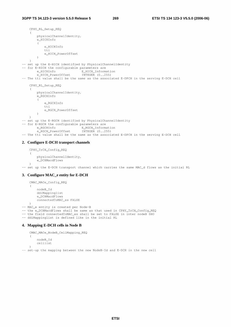
ETSI
ETSI TS 134 123-3 V5.5.0 (2006-06) 2693GPP TS 34.123-3 version 5.5.0 Release 5
CPHY_RL_Setup_REQ ( physicalChannelIdentity, e_HICHInfo ( e_HICHInfo tti e_HICH_PowerOffset ) } -- set up the E-HICH identified by PhysicalChannelIdentity -- for E-HICH the configurable parameters are e_HICHInfo E_HICH_Information e_HICH_PowerOffset INTEGER (0..255) -- The tti value shall be the same as the associated E-DPCH in the serving E-DCH cell CPHY_RL_Setup_REQ ( physicalChannelIdentity, e_RGCHInfo ( e_RGCHInfo tti e_RGCH_PowerOffset ) ) -- set up the E-RGCH identified by PhysicalChannelIdentity -- for E-RGCH the configurable parameters are e_RGCHInfo E_RGCH_Information e_RGCH_PowerOffset INTEGER (0..255) -- The tti value shall be the same as the associated E-DPCH in the serving E-DCH cell
2. Configure E-DCH transport channels
CPHY_TrCH_Config_REQ ( physicalChannelIdentity, e_DCHMacdFlows ) -- set up the E-DCH transport channel which carries the same MAC_d flows as the initial RL
3. Configure MAC_e entity for E-DCH
CMAC_MACe_Config_REQ ( nodeB_Id ddiMappinglist e_DCHMacdFlows connectedToMAC_es FALSE ) -- MAC_e entity is created per Node-B -- the e_DCHMacdFlows shall be same as that used in CPHY_TrCH_Config_REQ -- the field connectedToMAC_es shall be set to FALSE in inter nodeB SHO -- ddiMappinglist is defined like in the initial RL
4. Mapping E-DCH cells in Node B
CMAC_MACe_NodeB_CellMapping_REQ ( nodeB_Id celllist ) -- set-up the mapping between the new NodeB-Id and E-DCH in the new cell
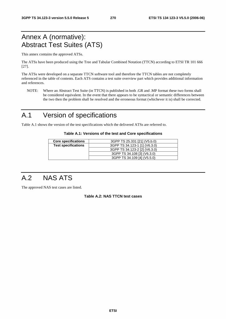
ETSI
ETSI TS 134 123-3 V5.5.0 (2006-06) 2703GPP TS 34.123-3 version 5.5.0 Release 5
Annex A (normative): Abstract Test Suites (ATS) This annex contains the approved ATSs.
The ATSs have been produced using the Tree and Tabular Combined Notation (TTCN) according to ETSI TR 101 666 [27].
The ATSs were developed on a separate TTCN software tool and therefore the TTCN tables are not completely referenced in the table of contents. Each ATS contains a test suite overview part which provides additional information and references.
NOTE: Where an Abstract Test Suite (in TTCN) is published in both .GR and .MP format these two forms shall be considered equivalent. In the event that there appears to be syntactical or semantic differences between the two then the problem shall be resolved and the erroneous format (whichever it is) shall be corrected.
A.1 Version of specifications Table A.1 shows the version of the test specifications which the delivered ATSs are referred to.
Table A.1: Versions of the test and Core specifications
Core specifications 3GPP TS 25.331 [21] (V5.b.0) 3GPP TS 34.123-1 [1] (V6.3.0) 3GPP TS 34.123-2 [2] (V6.3.0) 3GPP TS 34.108 [3] (V6.3.0)
Test specifications
3GPP TS 34.109 [4] (V5.5.0)
A.2 NAS ATS The approved NAS test cases are listed.
Table A.2: NAS TTCN test cases
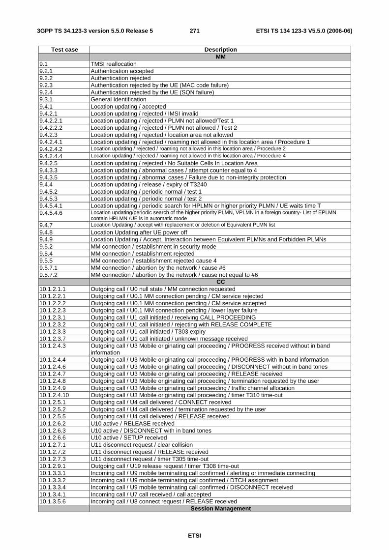
ETSI
ETSI TS 134 123-3 V5.5.0 (2006-06) 2713GPP TS 34.123-3 version 5.5.0 Release 5
Test case Description MM
9.1 TMSI reallocation 9.2.1 Authentication accepted 9.2.2 Authentication rejected 9.2.3 Authentication rejected by the UE (MAC code failure) 9.2.4 Authentication rejected by the UE (SQN failure) 9.3.1 General Identification 9.4.1 Location updating / accepted 9.4.2.1 Location updating / rejected / IMSI invalid 9.4.2.2.1 Location updating / rejected / PLMN not allowed/Test 1 9.4.2.2.2 Location updating / rejected / PLMN not allowed / Test 2 9.4.2.3 Location updating / rejected / location area not allowed 9.4.2.4.1 Location updating / rejected / roaming not allowed in this location area / Procedure 1 9.4.2.4.2 Location updating / rejected / roaming not allowed in this location area / Procedure 2 9.4.2.4.4 Location updating / rejected / roaming not allowed in this location area / Procedure 4
9.4.2.5 Location updating / rejected / No Suitable Cells In Location Area 9.4.3.3 Location updating / abnormal cases / attempt counter equal to 4 9.4.3.5 Location updating / abnormal cases / Failure due to non-integrity protection 9.4.4 Location updating / release / expiry of T3240 9.4.5.2 Location updating / periodic normal / test 1 9.4.5.3 Location updating / periodic normal / test 2 9.4.5.4.1 Location updating / periodic search for HPLMN or higher priority PLMN / UE waits time T 9.4.5.4.6 Location updating/periodic search of the higher priority PLMN, VPLMN in a foreign country- List of EPLMN
contain HPLMN /UE is in automatic mode 9.4.7 Location Updating / accept with replacement or deletion of Equivalent PLMN list 9.4.8 Location Updating after UE power off 9.4.9 Location Updating / Accept, Interaction between Equivalent PLMNs and Forbidden PLMNs 9.5.2 MM connection / establishment in security mode 9.5.4 MM connection / establishment rejected 9.5.5 MM connection / establishment rejected cause 4 9.5.7.1 MM connection / abortion by the network / cause #6 9.5.7.2 MM connection / abortion by the network / cause not equal to #6 CC 10.1.2.1.1 Outgoing call / U0 null state / MM connection requested 10.1.2.2.1 Outgoing call / U0.1 MM connection pending / CM service rejected 10.1.2.2.2 Outgoing call / U0.1 MM connection pending / CM service accepted 10.1.2.2.3 Outgoing call / U0.1 MM connection pending / lower layer failure 10.1.2.3.1 Outgoing call / U1 call initiated / receiving CALL PROCEEDING 10.1.2.3.2 Outgoing call / U1 call initiated / rejecting with RELEASE COMPLETE 10.1.2.3.3 Outgoing call / U1 call initiated / T303 expiry 10.1.2.3.7 Outgoing call / U1 call initiated / unknown message received 10.1.2.4.3 Outgoing call / U3 Mobile originating call proceeding / PROGRESS received without in band
information 10.1.2.4.4 Outgoing call / U3 Mobile originating call proceeding / PROGRESS with in band information 10.1.2.4.6 Outgoing call / U3 Mobile originating call proceeding / DISCONNECT without in band tones 10.1.2.4.7 Outgoing call / U3 Mobile originating call proceeding / RELEASE received 10.1.2.4.8 Outgoing call / U3 Mobile originating call proceeding / termination requested by the user 10.1.2.4.9 Outgoing call / U3 Mobile originating call proceeding / traffic channel allocation 10.1.2.4.10 Outgoing call / U3 Mobile originating call proceeding / timer T310 time-out 10.1.2.5.1 Outgoing call / U4 call delivered / CONNECT received 10.1.2.5.2 Outgoing call / U4 call delivered / termination requested by the user 10.1.2.5.5 Outgoing call / U4 call delivered / RELEASE received 10.1.2.6.2 U10 active / RELEASE received 10.1.2.6.3 U10 active / DISCONNECT with in band tones 10.1.2.6.6 U10 active / SETUP received 10.1.2.7.1 U11 disconnect request / clear collision 10.1.2.7.2 U11 disconnect request / RELEASE received 10.1.2.7.3 U11 disconnect request / timer T305 time-out 10.1.2.9.1 Outgoing call / U19 release request / timer T308 time-out 10.1.3.3.1 Incoming call / U9 mobile terminating call confirmed / alerting or immediate connecting 10.1.3.3.2 Incoming call / U9 mobile terminating call confirmed / DTCH assignment 10.1.3.3.4 Incoming call / U9 mobile terminating call confirmed / DISCONNECT received 10.1.3.4.1 Incoming call / U7 call received / call accepted 10.1.3.5.6 Incoming call / U8 connect request / RELEASE received Session Management
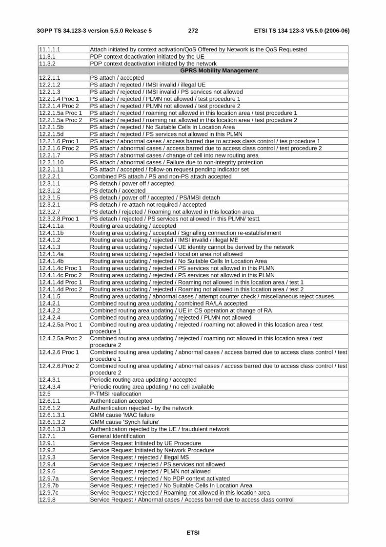
ETSI
ETSI TS 134 123-3 V5.5.0 (2006-06) 2723GPP TS 34.123-3 version 5.5.0 Release 5
11.1.1.1 Attach initiated by context activation/QoS Offered by Network is the QoS Requested 11.3.1 PDP context deactivation initiated by the UE 11.3.2 PDP context deactivation initiated by the network
GPRS Mobility Management 12.2.1.1 PS attach / accepted 12.2.1.2 PS attach / rejected / IMSI invalid / illegal UE 12.2.1.3 PS attach / rejected / IMSI invalid / PS services not allowed 12.2.1.4 Proc 1 PS attach / rejected / PLMN not allowed / test procedure 1 12.2.1.4 Proc 2 PS attach / rejected / PLMN not allowed / test procedure 2 12.2.1.5a Proc 1 PS attach / rejected / roaming not allowed in this location area / test procedure 1 12.2.1.5a Proc 2 PS attach / rejected / roaming not allowed in this location area / test procedure 2 12.2.1.5b PS attach / rejected / No Suitable Cells In Location Area 12.2.1.5d PS attach / rejected / PS services not allowed in this PLMN 12.2.1.6 Proc 1 PS attach / abnormal cases / access barred due to access class control / tes procedure 1 12.2.1.6 Proc 2 PS attach / abnormal cases / access barred due to access class control / test procedure 2 12.2.1.7 PS attach / abnormal cases / change of cell into new routing area 12.2.1.10 PS attach / abnormal cases / Failure due to non-integrity protection 12.2.1.11 PS attach / accepted / follow-on request pending indicator set 12.2.2.1 Combined PS attach / PS and non-PS attach accepted 12.3.1.1 PS detach / power off / accepted 12.3.1.2 PS detach / accepted 12.3.1.5 PS detach / power off / accepted / PS/IMSI detach 12.3.2.1 PS detach / re-attach not required / accepted 12.3.2.7 PS detach / rejected / Roaming not allowed in this location area 12.3.2.8.Proc 1 PS detach / rejected / PS services not allowed in this PLMN/ test1 12.4.1.1a Routing area updating / accepted 12.4.1.1b Routing area updating / accepted / Signalling connection re-establishment 12.4.1.2 Routing area updating / rejected / IMSI invalid / illegal ME 12.4.1.3 Routing area updating / rejected / UE identity cannot be derived by the network 12.4.1.4a Routing area updating / rejected / location area not allowed 12.4.1.4b Routing area updating / rejected / No Suitable Cells In Location Area 12.4.1.4c Proc 1 Routing area updating / rejected / PS services not allowed in this PLMN 12.4.1.4c Proc 2 Routing area updating / rejected / PS services not allowed in this PLMN 12.4.1.4d Proc 1 Routing area updating / rejected / Roaming not allowed in this location area / test 1 12.4.1.4d Proc 2 Routing area updating / rejected / Roaming not allowed in this location area / test 2 12.4.1.5 Routing area updating / abnormal cases / attempt counter check / miscellaneous reject causes 12.4.2.1 Combined routing area updating / combined RA/LA accepted 12.4.2.2 Combined routing area updating / UE in CS operation at change of RA 12.4.2.4 Combined routing area updating / rejected / PLMN not allowed 12.4.2.5a Proc 1 Combined routing area updating / rejected / roaming not allowed in this location area / test
procedure 1 12.4.2.5a.Proc 2 Combined routing area updating / rejected / roaming not allowed in this location area / test
procedure 2 12.4.2.6 Proc 1 Combined routing area updating / abnormal cases / access barred due to access class control / test
procedure 1 12.4.2.6.Proc 2 Combined routing area updating / abnormal cases / access barred due to access class control / test
procedure 2 12.4.3.1 Periodic routing area updating / accepted 12.4.3.4 Periodic routing area updating / no cell available 12.5 P-TMSI reallocation 12.6.1.1 Authentication accepted 12.6.1.2 Authentication rejected - by the network 12.6.1.3.1 GMM cause 'MAC failure 12.6.1.3.2 GMM cause 'Synch failure' 12.6.1.3.3 Authentication rejected by the UE / fraudulent network 12.7.1 General Identification 12.9.1 Service Request Initiated by UE Procedure 12.9.2 Service Request Initiated by Network Procedure 12.9.3 Service Request / rejected / Illegal MS 12.9.4 Service Request / rejected / PS services not allowed 12.9.6 Service Request / rejected / PLMN not allowed 12.9.7a Service Request / rejected / No PDP context activated 12.9.7b Service Request / rejected / No Suitable Cells In Location Area 12.9.7c Service Request / rejected / Roaming not allowed in this location area 12.9.8 Service Request / Abnormal cases / Access barred due to access class control
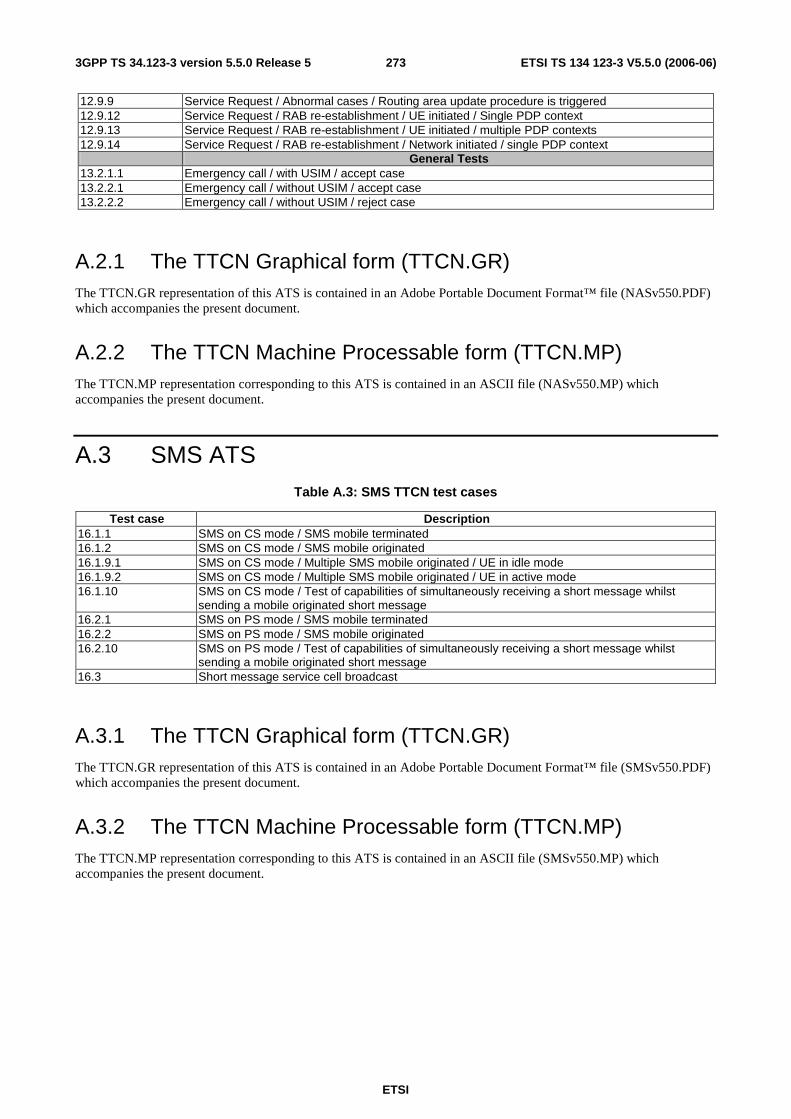
ETSI
ETSI TS 134 123-3 V5.5.0 (2006-06) 2733GPP TS 34.123-3 version 5.5.0 Release 5
12.9.9 Service Request / Abnormal cases / Routing area update procedure is triggered 12.9.12 Service Request / RAB re-establishment / UE initiated / Single PDP context 12.9.13 Service Request / RAB re-establishment / UE initiated / multiple PDP contexts 12.9.14 Service Request / RAB re-establishment / Network initiated / single PDP context
General Tests 13.2.1.1 Emergency call / with USIM / accept case 13.2.2.1 Emergency call / without USIM / accept case 13.2.2.2 Emergency call / without USIM / reject case
A.2.1 The TTCN Graphical form (TTCN.GR) The TTCN.GR representation of this ATS is contained in an Adobe Portable Document Format™ file (NASv550.PDF) which accompanies the present document.
A.2.2 The TTCN Machine Processable form (TTCN.MP) The TTCN.MP representation corresponding to this ATS is contained in an ASCII file (NASv550.MP) which accompanies the present document.
A.3 SMS ATS Table A.3: SMS TTCN test cases
Test case Description 16.1.1 SMS on CS mode / SMS mobile terminated 16.1.2 SMS on CS mode / SMS mobile originated 16.1.9.1 SMS on CS mode / Multiple SMS mobile originated / UE in idle mode 16.1.9.2 SMS on CS mode / Multiple SMS mobile originated / UE in active mode 16.1.10 SMS on CS mode / Test of capabilities of simultaneously receiving a short message whilst
sending a mobile originated short message 16.2.1 SMS on PS mode / SMS mobile terminated 16.2.2 SMS on PS mode / SMS mobile originated 16.2.10 SMS on PS mode / Test of capabilities of simultaneously receiving a short message whilst
sending a mobile originated short message 16.3 Short message service cell broadcast
A.3.1 The TTCN Graphical form (TTCN.GR) The TTCN.GR representation of this ATS is contained in an Adobe Portable Document Format™ file (SMSv550.PDF) which accompanies the present document.
A.3.2 The TTCN Machine Processable form (TTCN.MP) The TTCN.MP representation corresponding to this ATS is contained in an ASCII file (SMSv550.MP) which accompanies the present document.
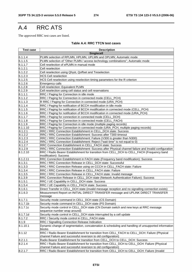
ETSI
ETSI TS 134 123-3 V5.5.0 (2006-06) 2743GPP TS 34.123-3 version 5.5.0 Release 5
A.4 RRC ATS The approved RRC test cases are listed.
Table A.4: RRC TTCN test cases
Test case Description Singlecell
6.1.1.4 PLMN selection of RPLMN, HPLMN, UPLMN and OPLMN; Automatic mode 6.1.1.5 PLMN selection of "Other PLMN / access technology combinations"; Automatic mode 6.1.1.7 Cell reselection of ePLMN in manual mode 6.1.2.1 Cell reselection 6.1.2.2 Cell reselection using Qhyst, Qoffset and Treselection 6.1.2.3 HCS Cell reselection 6.1.2.5 HCS Cell reselection using reselection timing parameters for the R criterion 6.1.2.6 Emergency calls 6.1.2.8 Cell reselection: Equivalent PLMN 6.1.2.9 Cell reselection using cell status and cell reservations 8.1.1.1 RRC / Paging for Connection in idle mode 8.1.1.2 RRC / Paging for Connection in connected mode (CELL_PCH) 8.1.1.3 R RRC / Paging for Connection in connected mode (URA_PCH) 8.1.1.4 RRC / Paging for notification of BCCH modification in idle mode 8.1.1.5 RRC / Paging for notification of BCCH modification in connected mode (CELL_PCH) 8.1.1.6 RRC / Paging for notification of BCCH modification in connected mode (URA_PCH) 8.1.1.7 RRC / Paging for connection in connected mode (CELL_DCH) 8.1.1.8 RRC / Paging for Connection in connected mode (CELL_FACH) 8.1.1.9 RRC / Paging for Connection in idle mode (multiple paging records) 8.1.1.10 RRC / Paging for Connection in connected mode (URA_PCH, multiple paging records) 8.1.2.1 RRC / RRC Connection Establishment in CELL_DCH state: Success 8.1.2.2 RRC / RRC Connection Establishment: Success after T300 timeout 8.1.2.3 RRC / RRC Connection Establishment: Failure (V300 is greater than N300) 8.1.2.4 RRC / RRC Connection Establishment: Reject ("wait time" is not equal to 0) 8.1.2.7 RRC Connection Establishment in CELL_FACH state: Success 8.1.2.9 RRC / RRC Connection Establishment: Success after Physical channel failure and Invalid configuration 8.1.2.10 RRC / Radio Bearer Establishment for transition from CELL_DCH to CELL_FACH (Frequency band
modification): Success 8.1.2.11 RRC Connection Establishment in FACH state (Frequency band modification): Success 8.1.3.1 RRC / RRC Connection Release in CELL_DCH state: Successful 8.1.3.3 RRC / RRC Connection Release using on CCCH in CELL_FACH state: Failure 8.1.3.4 RRC / RRC Connection Release in CELL_FACH state: Failure 8.1.3.5 RRC / RRC Connection Release in CELL_FACH state: Invalid message 8.1.3.9 RRC Connection Release in CELL_DCH state (Network Authentication Failure): Success 8.1.5.1 RRC / UE Capability in CELL_DCH state: Success 8.1.5.4 RRC / UE Capability in CELL_FACH state: Success 8.1.6.1 Direct Transfer in CELL_DCH state (invalid message reception and no signalling connection exists) 8.1.6.3 Measurement Report on INITIAL DIRECT TRANSFER message and UPLINK DIRECT TRANSFER
message 8.1.7.1 Security mode command in CELL_DCH state (CS Domain) 8.1.7.1b Security mode command in CELL_DCH state (PS Domain) 8.1.7.1c Security mode control in CELL_DCH state (CN Domain switch and new keys at RRC message
sequence number wrap around) 8.1.7.1d Security mode control in CELL_DCH state interrupted by a cell update 8.1.7.2 RRC / Security mode control in CELL_FACH state 8.1.9 RRC / Signalling Connection Release Indication 8.1.10.1 Dynamic change of segmentation, concatenation & scheduling and handling of unsupported information
blocks 8.1.12 RRC / Radio Bearer Establishment for transition from CELL_FACH to CELL_DCH: Failure (Physical
channel Failure and successful reversion to old configuration) 8.2.1.1 Radio Bearer Establishment for transition from CELL_DCH to CELL_DCH: Success 8.2.1.4 RRC / Radio Bearer Establishment for transition from CELL_DCH to CELL_DCH: Failure (Physical
channel Failure and successful reversion to old configuration) 8.2.1.7 RRC / Radio Bearer Establishment for transition from CELL_DCH to CELL_DCH: Failure (Invalid
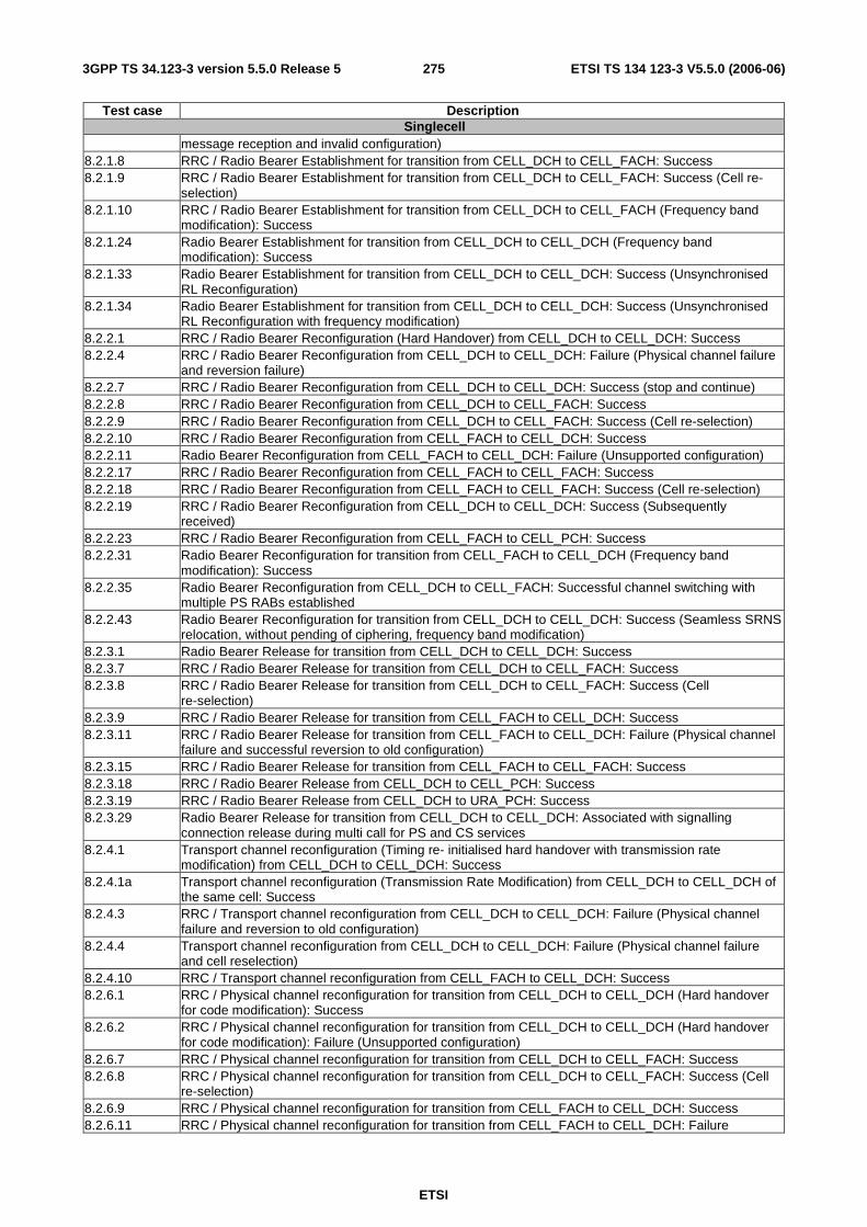
ETSI
ETSI TS 134 123-3 V5.5.0 (2006-06) 2753GPP TS 34.123-3 version 5.5.0 Release 5
Test case Description Singlecell
message reception and invalid configuration) 8.2.1.8 RRC / Radio Bearer Establishment for transition from CELL_DCH to CELL_FACH: Success 8.2.1.9 RRC / Radio Bearer Establishment for transition from CELL_DCH to CELL_FACH: Success (Cell re-
selection) 8.2.1.10 RRC / Radio Bearer Establishment for transition from CELL_DCH to CELL_FACH (Frequency band
modification): Success 8.2.1.24 Radio Bearer Establishment for transition from CELL_DCH to CELL_DCH (Frequency band
modification): Success 8.2.1.33 Radio Bearer Establishment for transition from CELL_DCH to CELL_DCH: Success (Unsynchronised
RL Reconfiguration) 8.2.1.34 Radio Bearer Establishment for transition from CELL_DCH to CELL_DCH: Success (Unsynchronised
RL Reconfiguration with frequency modification) 8.2.2.1 RRC / Radio Bearer Reconfiguration (Hard Handover) from CELL_DCH to CELL_DCH: Success 8.2.2.4 RRC / Radio Bearer Reconfiguration from CELL_DCH to CELL_DCH: Failure (Physical channel failure
and reversion failure) 8.2.2.7 RRC / Radio Bearer Reconfiguration from CELL_DCH to CELL_DCH: Success (stop and continue) 8.2.2.8 RRC / Radio Bearer Reconfiguration from CELL_DCH to CELL_FACH: Success 8.2.2.9 RRC / Radio Bearer Reconfiguration from CELL_DCH to CELL_FACH: Success (Cell re-selection) 8.2.2.10 RRC / Radio Bearer Reconfiguration from CELL_FACH to CELL_DCH: Success 8.2.2.11 Radio Bearer Reconfiguration from CELL_FACH to CELL_DCH: Failure (Unsupported configuration) 8.2.2.17 RRC / Radio Bearer Reconfiguration from CELL_FACH to CELL_FACH: Success 8.2.2.18 RRC / Radio Bearer Reconfiguration from CELL_FACH to CELL_FACH: Success (Cell re-selection) 8.2.2.19 RRC / Radio Bearer Reconfiguration from CELL_DCH to CELL_DCH: Success (Subsequently
received) 8.2.2.23 RRC / Radio Bearer Reconfiguration from CELL_FACH to CELL_PCH: Success 8.2.2.31 Radio Bearer Reconfiguration for transition from CELL_FACH to CELL_DCH (Frequency band
modification): Success 8.2.2.35 Radio Bearer Reconfiguration from CELL_DCH to CELL_FACH: Successful channel switching with
multiple PS RABs established 8.2.2.43 Radio Bearer Reconfiguration for transition from CELL_DCH to CELL_DCH: Success (Seamless SRNS
relocation, without pending of ciphering, frequency band modification) 8.2.3.1 Radio Bearer Release for transition from CELL_DCH to CELL_DCH: Success 8.2.3.7 RRC / Radio Bearer Release for transition from CELL_DCH to CELL_FACH: Success 8.2.3.8 RRC / Radio Bearer Release for transition from CELL_DCH to CELL_FACH: Success (Cell
re-selection) 8.2.3.9 RRC / Radio Bearer Release for transition from CELL_FACH to CELL_DCH: Success 8.2.3.11 RRC / Radio Bearer Release for transition from CELL_FACH to CELL_DCH: Failure (Physical channel
failure and successful reversion to old configuration) 8.2.3.15 RRC / Radio Bearer Release for transition from CELL_FACH to CELL_FACH: Success 8.2.3.18 RRC / Radio Bearer Release from CELL_DCH to CELL_PCH: Success 8.2.3.19 RRC / Radio Bearer Release from CELL_DCH to URA_PCH: Success 8.2.3.29 Radio Bearer Release for transition from CELL_DCH to CELL_DCH: Associated with signalling
connection release during multi call for PS and CS services 8.2.4.1 Transport channel reconfiguration (Timing re- initialised hard handover with transmission rate
modification) from CELL_DCH to CELL_DCH: Success 8.2.4.1a Transport channel reconfiguration (Transmission Rate Modification) from CELL_DCH to CELL_DCH of
the same cell: Success 8.2.4.3 RRC / Transport channel reconfiguration from CELL_DCH to CELL_DCH: Failure (Physical channel
failure and reversion to old configuration) 8.2.4.4 Transport channel reconfiguration from CELL_DCH to CELL_DCH: Failure (Physical channel failure
and cell reselection) 8.2.4.10 RRC / Transport channel reconfiguration from CELL_FACH to CELL_DCH: Success 8.2.6.1 RRC / Physical channel reconfiguration for transition from CELL_DCH to CELL_DCH (Hard handover
for code modification): Success 8.2.6.2 RRC / Physical channel reconfiguration for transition from CELL_DCH to CELL_DCH (Hard handover
for code modification): Failure (Unsupported configuration) 8.2.6.7 RRC / Physical channel reconfiguration for transition from CELL_DCH to CELL_FACH: Success 8.2.6.8 RRC / Physical channel reconfiguration for transition from CELL_DCH to CELL_FACH: Success (Cell
re-selection) 8.2.6.9 RRC / Physical channel reconfiguration for transition from CELL_FACH to CELL_DCH: Success 8.2.6.11 RRC / Physical channel reconfiguration for transition from CELL_FACH to CELL_DCH: Failure
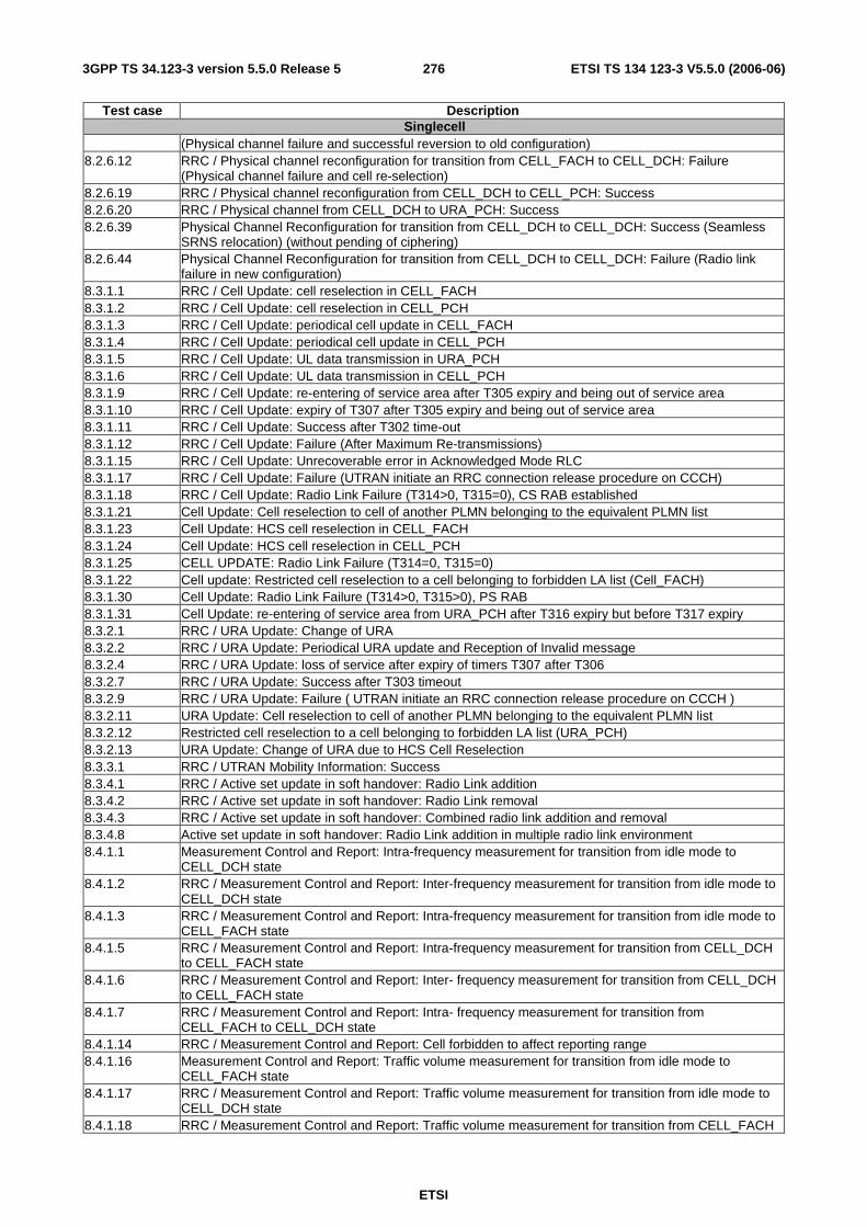
ETSI
ETSI TS 134 123-3 V5.5.0 (2006-06) 2763GPP TS 34.123-3 version 5.5.0 Release 5
Test case Description Singlecell
(Physical channel failure and successful reversion to old configuration) 8.2.6.12 RRC / Physical channel reconfiguration for transition from CELL_FACH to CELL_DCH: Failure
(Physical channel failure and cell re-selection) 8.2.6.19 RRC / Physical channel reconfiguration from CELL_DCH to CELL_PCH: Success 8.2.6.20 RRC / Physical channel from CELL_DCH to URA_PCH: Success 8.2.6.39 Physical Channel Reconfiguration for transition from CELL_DCH to CELL_DCH: Success (Seamless
SRNS relocation) (without pending of ciphering) 8.2.6.44 Physical Channel Reconfiguration for transition from CELL_DCH to CELL_DCH: Failure (Radio link
failure in new configuration) 8.3.1.1 RRC / Cell Update: cell reselection in CELL_FACH 8.3.1.2 RRC / Cell Update: cell reselection in CELL_PCH 8.3.1.3 RRC / Cell Update: periodical cell update in CELL_FACH 8.3.1.4 RRC / Cell Update: periodical cell update in CELL_PCH 8.3.1.5 RRC / Cell Update: UL data transmission in URA_PCH 8.3.1.6 RRC / Cell Update: UL data transmission in CELL_PCH 8.3.1.9 RRC / Cell Update: re-entering of service area after T305 expiry and being out of service area 8.3.1.10 RRC / Cell Update: expiry of T307 after T305 expiry and being out of service area 8.3.1.11 RRC / Cell Update: Success after T302 time-out 8.3.1.12 RRC / Cell Update: Failure (After Maximum Re-transmissions) 8.3.1.15 RRC / Cell Update: Unrecoverable error in Acknowledged Mode RLC 8.3.1.17 RRC / Cell Update: Failure (UTRAN initiate an RRC connection release procedure on CCCH) 8.3.1.18 RRC / Cell Update: Radio Link Failure (T314>0, T315=0), CS RAB established 8.3.1.21 Cell Update: Cell reselection to cell of another PLMN belonging to the equivalent PLMN list 8.3.1.23 Cell Update: HCS cell reselection in CELL_FACH 8.3.1.24 Cell Update: HCS cell reselection in CELL_PCH 8.3.1.25 CELL UPDATE: Radio Link Failure (T314=0, T315=0) 8.3.1.22 Cell update: Restricted cell reselection to a cell belonging to forbidden LA list (Cell_FACH) 8.3.1.30 Cell Update: Radio Link Failure (T314>0, T315>0), PS RAB 8.3.1.31 Cell Update: re-entering of service area from URA_PCH after T316 expiry but before T317 expiry 8.3.2.1 RRC / URA Update: Change of URA 8.3.2.2 RRC / URA Update: Periodical URA update and Reception of Invalid message 8.3.2.4 RRC / URA Update: loss of service after expiry of timers T307 after T306 8.3.2.7 RRC / URA Update: Success after T303 timeout 8.3.2.9 RRC / URA Update: Failure ( UTRAN initiate an RRC connection release procedure on CCCH ) 8.3.2.11 URA Update: Cell reselection to cell of another PLMN belonging to the equivalent PLMN list 8.3.2.12 Restricted cell reselection to a cell belonging to forbidden LA list (URA_PCH) 8.3.2.13 URA Update: Change of URA due to HCS Cell Reselection 8.3.3.1 RRC / UTRAN Mobility Information: Success 8.3.4.1 RRC / Active set update in soft handover: Radio Link addition 8.3.4.2 RRC / Active set update in soft handover: Radio Link removal 8.3.4.3 RRC / Active set update in soft handover: Combined radio link addition and removal 8.3.4.8 Active set update in soft handover: Radio Link addition in multiple radio link environment 8.4.1.1 Measurement Control and Report: Intra-frequency measurement for transition from idle mode to
CELL_DCH state 8.4.1.2 RRC / Measurement Control and Report: Inter-frequency measurement for transition from idle mode to
CELL_DCH state 8.4.1.3 RRC / Measurement Control and Report: Intra-frequency measurement for transition from idle mode to
CELL_FACH state 8.4.1.5 RRC / Measurement Control and Report: Intra-frequency measurement for transition from CELL_DCH
to CELL_FACH state 8.4.1.6 RRC / Measurement Control and Report: Inter- frequency measurement for transition from CELL_DCH
to CELL_FACH state 8.4.1.7 RRC / Measurement Control and Report: Intra- frequency measurement for transition from
CELL_FACH to CELL_DCH state 8.4.1.14 RRC / Measurement Control and Report: Cell forbidden to affect reporting range 8.4.1.16 Measurement Control and Report: Traffic volume measurement for transition from idle mode to
CELL_FACH state 8.4.1.17 RRC / Measurement Control and Report: Traffic volume measurement for transition from idle mode to
CELL_DCH state 8.4.1.18 RRC / Measurement Control and Report: Traffic volume measurement for transition from CELL_FACH

ETSI
ETSI TS 134 123-3 V5.5.0 (2006-06) 2773GPP TS 34.123-3 version 5.5.0 Release 5
Test case Description Singlecell
state to CELL_DCH state 8.4.1.19 RRC / Measurement Control and Report: Traffic volume measurement for transition from CELL_DCH to
CELL_FACH state 8.4.1.23 RRC / Measurement Control and Report: Intra-frequency measurement for events 1C and 1D 8.4.1.24 RRC / Measurement Control and Report: Inter-frequency measurement for event 2A 8.4.1.25 RRC / Measurement Control and Report: Inter-frequency measurement for events 2B and 2E 8.4.1.26 RRC / Measurement Control and Report: Inter-frequency measurement for events 2D and 2F 8.4.1.27 RRC / Measurement Control and Report: UE internal measurement for events 6A and 6B 8.4.1.29 RRC / Measurement Control and Report: Event based Traffic Volume measurement in CELL_FACH
state 8.4.1.30 RRC / Measurement Control and Report: Event based Traffic Volume measurement in CELL_DCH
state 8.4.1.37 Measurement Control and Report: UE internal measurement, event 6c 8.4.1.38 Measurement Control and Report: UE internal measurement, event 6d 8.4.1.41 Measurement Control and Report: Additional Measurements list
A.4.1 The TTCN Graphical form (TTCN.GR) The TTCN.GR representation of this ATS is contained in an Adobe Portable Document Format™ file (RRCv550.PDF) which accompanies the present document.
A.4.2 The TTCN Machine Processable form (TTCN.MP) The TTCN.MP representation corresponding to this ATS is contained in an ASCII file (RRCv550.MP) which accompanies the present document.
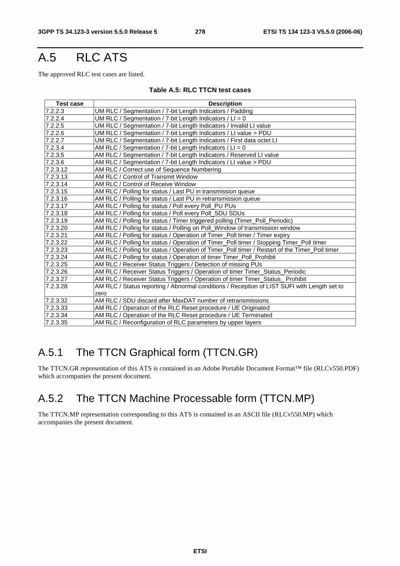
ETSI
ETSI TS 134 123-3 V5.5.0 (2006-06) 2783GPP TS 34.123-3 version 5.5.0 Release 5
A.5 RLC ATS The approved RLC test cases are listed.
Table A.5: RLC TTCN test cases
Test case Description 7.2.2.3 UM RLC / Segmentation / 7-bit Length Indicators / Padding 7.2.2.4 UM RLC / Segmentation / 7-bit Length Indicators / LI = 0 7.2.2.5 UM RLC / Segmentation / 7-bit Length Indicators / Invalid LI value 7.2.2.6 UM RLC / Segmentation / 7-bit Length Indicators / LI value > PDU 7.2.2.7 UM RLC / Segmentation / 7-bit Length Indicators / First data octet LI 7.2.3.4 AM RLC / Segmentation / 7-bit Length Indicators / LI = 0 7.2.3.5 AM RLC / Segmentation / 7-bit Length Indicators / Reserved LI value 7.2.3.6 AM RLC / Segmentation / 7-bit Length Indicators / LI value > PDU 7.2.3.12 AM RLC / Correct use of Sequence Numbering 7.2.3.13 AM RLC / Control of Transmit Window 7.2.3.14 AM RLC / Control of Receive Window 7.2.3.15 AM RLC / Polling for status / Last PU in transmission queue 7.2.3.16 AM RLC / Polling for status / Last PU in retransmission queue 7.2.3.17 AM RLC / Polling for status / Poll every Poll_PU PUs 7.2.3.18 AM RLC / Polling for status / Poll every Poll_SDU SDUs 7.2.3.19 AM RLC / Polling for status / Timer triggered polling (Timer_Poll_Periodic) 7.2.3.20 AM RLC / Polling for status / Polling on Poll_Window of transmission window 7.2.3.21 AM RLC / Polling for status / Operation of Timer_Poll timer / Timer expiry 7.2.3.22 AM RLC / Polling for status / Operation of Timer_Poll timer / Stopping Timer_Poll timer 7.2.3.23 AM RLC / Polling for status / Operation of Timer_Poll timer / Restart of the Timer_Poll timer 7.2.3.24 AM RLC / Polling for status / Operation of timer Timer_Poll_Prohibit 7.2.3.25 AM RLC / Receiver Status Triggers / Detection of missing PUs 7.2.3.26 AM RLC / Receiver Status Triggers / Operation of timer Timer_Status_Periodic 7.2.3.27 AM RLC / Receiver Status Triggers / Operation of timer Timer_Status_ Prohibit 7.2.3.28 AM RLC / Status reporting / Abnormal conditions / Reception of LIST SUFI with Length set to
zero 7.2.3.32 AM RLC / SDU discard after MaxDAT number of retransmissions 7.2.3.33 AM RLC / Operation of the RLC Reset procedure / UE Originated 7.2.3.34 AM RLC / Operation of the RLC Reset procedure / UE Terminated 7.2.3.35 AM RLC / Reconfiguration of RLC parameters by upper layers
A.5.1 The TTCN Graphical form (TTCN.GR) The TTCN.GR representation of this ATS is contained in an Adobe Portable Document Format™ file (RLCv550.PDF) which accompanies the present document.
A.5.2 The TTCN Machine Processable form (TTCN.MP) The TTCN.MP representation corresponding to this ATS is contained in an ASCII file (RLCv550.MP) which accompanies the present document.

ETSI
ETSI TS 134 123-3 V5.5.0 (2006-06) 2793GPP TS 34.123-3 version 5.5.0 Release 5
A.6 MAC ATS Table A.6: MAC TTCN test cases
Test case Description 7.1.1.1 CCCH mapped to RACH/FACH / Invalid TCTF 7.1.1.2 DTCH or DCCH mapped to RACH/FACH / Invalid TCTF 7.1.1.3 DTCH or DCCH mapped to RACH/FACH / Invalid C/T Field 7.1.1.4 DTCH or DCCH mapped to RACH/FACH / Invalid UE ID Type Field 7.1.1.5 DTCH or DCCH mapped to RACH/FACH / Incorrect UE ID 7.1.1.8 DTCH or DCCH mapped to DCH / Invalid C/T Field 7.1.2.3.1 Correct Selection of RACH parameters (FDD) 7.1.2.4a Access Service class selection for RACH transmission 7.1.3.1 Priority handling between data flows of one UE
A.6.1 The TTCN Graphical form (TTCN.GR) The TTCN.GR representation of this ATS is contained in an Adobe Portable Document Format™ file (MACv550.PDF) which accompanies the present document.
A.6.2 The TTCN Machine Processable form (TTCN.MP) The TTCN.MP representation corresponding to this ATS is contained in an ASCII file (MACv550.MP) which accompanies the present document.
A.7 BMC ATS Table A.7: BMC TTCN test cases
Test case Description - -
A.7.1 The TTCN Graphical form (TTCN.GR) The TTCN.GR representation of this ATS is contained in an Adobe Portable Document Format™ file (BMC.PDF) which accompanies the present document.
A.7.2 The TTCN Machine Processable form (TTCN.MP) The TTCN.MP representation corresponding to this ATS is contained in an ASCII file (BMC.MP) which accompanies the present document.
A.8 PDCP ATS Table A.8: PDCP TTCN test cases
Test case Description - -
ETSI
ETSI TS 134 123-3 V5.5.0 (2006-06) 2803GPP TS 34.123-3 version 5.5.0 Release 5
A.8.1 The TTCN Graphical form (TTCN.GR) The TTCN.GR representation of this ATS is contained in an Adobe Portable Document Format™ file (PDCP.PDF) which accompanies the present document.
A.8.2 The TTCN Machine Processable form (TTCN.MP) The TTCN.MP representation corresponding to this ATS is contained in an ASCII file (PDCP.MP) which accompanies the present document.
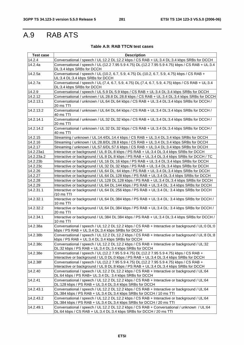
ETSI
ETSI TS 134 123-3 V5.5.0 (2006-06) 2813GPP TS 34.123-3 version 5.5.0 Release 5
A.9 RAB ATS Table A.9: RAB TTCN test cases
Test case Description 14.2.4 Conversational / speech / UL:12.2 DL:12.2 kbps / CS RAB + UL:3.4 DL:3.4 kbps SRBs for DCCH 14.2.4a Conversational / speech / UL:(12.2 7.95 5.9 4.75) DL:(12.2 7.95 5.9 4.75) kbps / CS RAB + UL:3.4
DL:3.4 kbps SRBs for DCCH 14.2.5a Conversational / speech / UL:(10.2, 6.7, 5.9, 4.75) DL:(10.2, 6.7, 5.9, 4.75) kbps / CS RAB +
UL:3.4 DL:3.4 kbps SRBs for DCCH 14.2.7a Conversational / speech / UL:(7.4, 6.7, 5.9, 4.75) DL:(7.4, 6.7, 5.9, 4.75) kbps / CS RAB + UL:3.4
DL:3.4 kbps SRBs for DCCH 14.2.9 Conversational / speech / UL:5.9 DL:5.9 kbps / CS RAB + UL:3.4 DL:3.4 kbps SRBs for DCCH 14.2.12 Conversational / unknown / UL:28.8 DL:28.8 kbps / CS RAB + UL:3.4 DL:3.4 kbps SRBs for DCCH 14.2.13.1 Conversational / unknown / UL:64 DL:64 kbps / CS RAB + UL:3.4 DL:3.4 kbps SRBs for DCCH /
20 ms TTI 14.2.13.2 Conversational / unknown / UL:64 DL:64 kbps / CS RAB + UL:3.4 DL:3.4 kbps SRBs for DCCH /
40 ms TTI 14.2.14.1 Conversational / unknown / UL:32 DL:32 kbps / CS RAB + UL:3.4 DL:3.4 kbps SRBs for DCCH /
20 ms TTI 14.2.14.2 Conversational / unknown / UL:32 DL:32 kbps / CS RAB + UL:3.4 DL:3.4 kbps SRBs for DCCH /
40 ms TTI 14.2.15 Streaming / unknown / UL:14.4/DL:14.4 kbps / CS RAB + UL:3.4 DL:3.4 kbps SRBs for DCCH 14.2.16 Streaming / unknown / UL:28.8/DL:28.8 kbps / CS RAB + UL:3.4 DL:3.4 kbps SRBs for DCCH 14.2.17 Streaming / unknown / UL:57.6/DL:57.6 kbps / CS RAB + UL:3.4 DL:3.4 kbps SRBs for DCCH 14.2.23a1 Interactive or background / UL:8 DL:8 kbps / PS RAB + UL:3.4 DL:3.4 kbps SRBs for DCCH 14.2.23a.2 Interactive or background / UL:8 DL:8 kbps / PS RAB + UL:3.4 DL:3.4 kbps SRBs for DCCH / TC 14.2.23b Interactive or background / UL:16 DL:16 kbps / PS RAB + UL:3.4 DL:3.4 kbps SRBs for DCCH 14.2.23c Interactive or background / UL:32 DL:32 kbps / PS RAB + UL:3.4 DL:3.4 kbps SRBs for DCCH 14.2.26 Interactive or background / UL:64 DL: 64 kbps / PS RAB + UL:3.4 DL:3.4 kbps SRBs for DCCH 14.2.27 Interactive or background / UL:64 DL:128 kbps / PS RAB + UL:3.4 DL:3.4 kbps SRBs for DCCH 14.2.28 Interactive or background / UL:128 DL:128 kbps / PS RAB + UL:3.4 DL:3.4 kbps SRBs for DCCH 14.2.29 Interactive or background / UL:64 DL:144 kbps / PS RAB + UL:3.4 DL: 3.4 kbps SRBs for DCCH 14.2.31.1 Interactive or background / UL:64 DL:256 kbps / PS RAB + UL:3.4 DL: 3.4 kbps SRBs for DCCH
/10 ms TTI 14.2.32.1 Interactive or background / UL:64 DL:384 kbps / PS RAB + UL:3.4 DL: 3.4 kbps SRBs for DCCH /
10 ms TTI 14.2.32.2 Interactive or background / UL:64 DL:384 kbps / PS RAB + UL:3.4 DL: 3.4 kbps SRBs for DCCH /
20 ms TTI 14.2.34.1 Interactive or background / UL:384 DL:384 kbps / PS RAB + UL:3.4 DL:3.4 kbps SRBs for DCCH /
10 ms TTI 14.2.38a Conversational / speech / UL:12.2 DL:12.2 kbps / CS RAB + Interactive or background / UL:0 DL:0
kbps / PS RAB + UL:3.4 DL:3.4 kbps SRBs for DCCH 14.2.38b Conversational / speech / UL:12.2 DL:12.2 kbps / CS RAB + Interactive or background / UL:8 DL:8
kbps / PS RAB + UL:3.4 DL:3.4 kbps SRBs for DCCH 14.2.38c Conversational / speech / UL:12.2 DL:12.2 kbps / CS RAB + Interactive or background / UL:32
DL:32 kbps / PS RAB + UL:3.4 DL:3.4 kbps SRBs for DCCH 14.2.38e Conversational / speech / UL:(12.2 7.95 5.9 4.75) DL:(12.2 7.95 5.9 4.75) kbps / CS RAB +
Interactive or background / UL:0 DL:0 kbps / PS RAB + UL:3.4 DL:3.4 kbps SRBs for DCCH 14.2.38f Conversational / speech / UL:(12.2 7.95 5.9 4.75) DL:(12.2 7.95 5.9 4.75) kbps / CS RAB +
Interactive or background / UL:8 DL:8 kbps / PS RAB + UL:3.4 DL:3.4 kbps SRBs for DCCH 14.2.40 Conversational / speech / UL:12.2 DL:12.2 kbps / CS RAB + Interactive or background / UL:64
DL:64 kbps / PS RAB+ UL:3.4 DL: 3.4 kbps SRBs for DCCH 14.2.41 Conversational / speech / UL:12.2 DL:12.2 kbps / CS RAB + Interactive or background / UL:64
DL:128 kbps / PS RAB + UL:3.4 DL:3.4 kbps SRBs for DCCH 14.2.43.1 Conversational / speech / UL:12.2 DL:12.2 kbps / CS RAB + Interactive or background / UL:64
DL:384 kbps / PS RAB + UL:3.4 DL:3.4 kbps SRBs for DCCH / 10 ms TTI 14.2.43.2 Conversational / speech / UL:12.2 DL:12.2 kbps / CS RAB + Interactive or background / UL:64
DL:384 kbps / PS RAB + UL:3.4 DL:3.4 kbps SRBs for DCCH / 20 ms TTI 14.2.49.1 Conversational / speech / UL:12.2 DL:12.2 kbps / CS RAB + Conversational / unknown / UL:64
DL:64 kbps / CS RAB + UL:3.4 DL:3.4 kbps SRBs for DCCH / 20 ms TTI
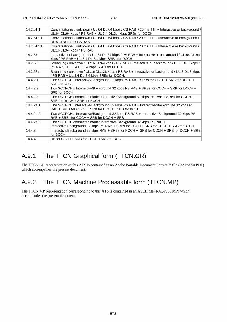
ETSI
ETSI TS 134 123-3 V5.5.0 (2006-06) 2823GPP TS 34.123-3 version 5.5.0 Release 5
14.2.51.1 Conversational / unknown / UL:64 DL:64 kbps / CS RAB / 20 ms TTI + Interactive or background / UL:64 DL:64 kbps / PS RAB + UL:3.4 DL:3.4 kbps SRBs for DCCH
14.2.51a.1 Conversational / unknown / UL:64 DL:64 kbps / CS RAB / 20 ms TTI + Interactive or background / UL:8 DL:8 kbps / PS RAB
14.2.51b.1 Conversational / unknown / UL:64 DL:64 kbps / CS RAB / 20 ms TTI + Interactive or background / UL:16 DL:64 kbps / PS RAB
14.2.57 Interactive or background / UL:64 DL:64 kbps / PS RAB + Interactive or background / UL:64 DL:64 kbps / PS RAB + UL:3.4 DL:3.4 kbps SRBs for DCCH
14.2.58 Streaming / unknown / UL:16 DL:64 kbps / PS RAB + Interactive or background / UL:8 DL:8 kbps / PS RAB + UL:3.4 DL:3.4 kbps SRBs for DCCH.
14.2.58a Streaming / unknown / UL:16 DL:128 kbps / PS RAB + Interactive or background / UL:8 DL:8 kbps / PS RAB + UL:3.4 DL:3.4 kbps SRBs for DCCH.
14.4.2.1 One SCCPCH: Interactive/Background 32 kbps PS RAB + SRBs for CCCH + SRB for DCCH + SRB for BCCH
14.4.2.2 Two SCCPCHs: Interactive/Background 32 kbps PS RAB + SRBs for CCCH + SRB for DCCH + SRB for BCCH
14.4.2.3 One SCCPCH/connected mode: Interactive/Background 32 kbps PS RAB + SRBs for CCCH + SRB for DCCH + SRB for BCCH
14.4.2a.1 One SCCPCH: Interactive/Background 32 kbps PS RAB + Interactive/Background 32 kbps PS RAB + SRBs for CCCH + SRB for DCCH + SRB for BCCH
14.4.2a.2 Two SCCPCHs: Interactive/Background 32 kbps PS RAB + Interactive/Background 32 kbps PS RAB + SRBs for CCCH + SRB for DCCH + SRB
14.4.2a.3 One SCCPCH/connected mode: Interactive/Background 32 kbps PS RAB + Interactive/Background 32 kbps PS RAB + SRBs for CCCH + SRB for DCCH + SRB for BCCH
14.4.3 Interactive/Background 32 kbps RAB + SRBs for PCCH + SRB for CCCH + SRB for DCCH + SRB for BCCH
14.4.4 RB for CTCH + SRB for CCCH +SRB for BCCH
A.9.1 The TTCN Graphical form (TTCN.GR) The TTCN.GR representation of this ATS is contained in an Adobe Portable Document Format™ file (RABv550.PDF) which accompanies the present document.
A.9.2 The TTCN Machine Processable form (TTCN.MP) The TTCN.MP representation corresponding to this ATS is contained in an ASCII file (RABv550.MP) which accompanies the present document.

ETSI
ETSI TS 134 123-3 V5.5.0 (2006-06) 2833GPP TS 34.123-3 version 5.5.0 Release 5
A.10 IR_U ATS Table A.10: InterRat TTCN test cases
Test case Description 6.2.1.1 Selection of the correct PLMN and associated RAT 6.2.1.6 Selection of RAT for HPLMN; Automatic mode 6.2.1.7 Selection of RAT for UPLMN; Automatic mode 6.2.1.8 Selection of RAT for OPLMN; Automatic mode 6.2.1.9 Selection of "Other PLMN / access technology combinations"; Automatic mode 6.2.2.1 Cell reselection if cell becomes barred or S<0; UTRAN to GSM 6.2.2.2 Cell reselection if cell becomes barred or C1<0; GSM to; UTRAN 6.2.2.3 Cell reselection timings; GSM to UTRAN 8.1.2.12 RRC Connection Establishment: Reject with interRATInfo is set to GSM 8.1.2.13 RRC Connection Establishment: Reject with InterRATInfo is set to GSM and selection to the
designated system fails 8.3.7.1 Inter system handover from UTRAN/To GSM/Speech/Success 8.3.7.2 Inter system handover from UTRAN/To GSM/Data/Same data rate/Success 8.3.7.3 Inter system handover from UTRAN/To GSM/Data/Data rate down grading/Success 8.3.7.4 Inter system handover from UTRAN/To GSM/Speech/Establishment/Success 8.3.7.5 Inter system handover from UTRAN/To GSM/Speech/Failure 8.3.7.7 Inter system handover from UTRAN/To GSM/Speech/Failure (L1 Synchronization) 8.3.7.9 Inter system handover from UTRAN/To GSM/Speech/Failure (Unsupported configuration) 8.3.7.12 Inter system handover from UTRAN/To GSM/Speech/Failure (Physical channel Failure and
Reversion Failure) 8.3.7.13 Inter system handover from UTRAN/To GSM/ success / call under establishment 8.3.7.16 Inter system handover from UTRAN/To GSM/Simultaneous CS and PS domain
services/Success/TBF Establishment Success 8.3.9.1 Cell reselection if cell becomes barred or S<0; UTRAN to GPRS (CELL_FACH) 8.3.9.3 Cell reselection fails if S<0; UTRAN to GPRS (CELL_FACH) 8.3.9.5 Cell Reselection with RAU - Qoffset value modification; UTRAN to GPRS (CELL_FACH) 8.3.11.1 Cell change order from UTRAN/To GPRS/CELL_DCH/Success 8.3.11.4 Cell change order from UTRAN/To GPRS/CELL_DCH/Failure (Physical channel & Reversion
Failure) 8.4.1.31 RRC / Measurement Control and Report: Inter-RAT measurement in CELL_DCH state 8.4.1.33 Measurement Control and Report: Inter-RAT measurement, event 3a 8.4.1.34 Measurement Control and Report: Inter-RAT measurement, event 3b 8.4.1.35 Measurement Control and Report: Inter-RAT measurement, event 3c 8.4.1.36 Measurement Control and Report: Inter-RAT measurement, event 3d 8.4.1.40 Measurement Control and Report: Inter-RAT measurement event 3C in CELL_DCH state using
sparse compressed mode pattern 8.4.1.48 Measurement Control and Report: Combined Inter-frequency measurement for event 2b and
Inter-RAT measurement, event 3a (FDD) 12.8 GMM READY timer handling
A.10.1 The TTCN Graphical form (TTCN.GR) The TTCN.GR representation of this ATS is contained in an Adobe Portable Document Format™ file (IR_Uv550.PDF) which accompanies the present document.
A.10.2 The TTCN Machine Processable form (TTCN.MP) The TTCN.MP representation corresponding to this ATS is contained in an ASCII file (IR_Uv550.MP) which accompanies the present document.
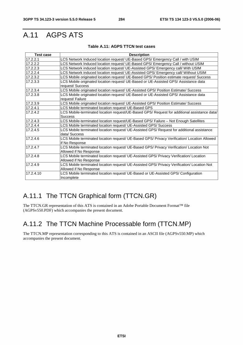
ETSI
ETSI TS 134 123-3 V5.5.0 (2006-06) 2843GPP TS 34.123-3 version 5.5.0 Release 5
A.11 AGPS ATS Table A.11: AGPS TTCN test cases
Test case Description 17.2.2.1 LCS Network Induced location request/ UE-Based GPS/ Emergency Call / with USIM 17.2.2.2 LCS Network Induced location request/ UE-Based GPS/ Emergency Call / without USIM 17.2.2.3 LCS Network induced location request/ UE-Assisted GPS/ Emergency call/ With USIM 17.2.2.4 LCS Network induced location request/ UE-Assisted GPS/ Emergency call/ Without USIM 17.2.3.2 LCS Mobile originated location request/ UE-Based GPS/ Position estimate request/ Success 17.2.3.3 LCS Mobile originated location request/ UE-Based or UE-Assisted GPS/ Assistance data
request/ Success 17.2.3.4 LCS Mobile originated location request/ UE-Assisted GPS/ Position Estimate/ Success 17.2.3.8 LCS Mobile originated location request/ UE-Based or UE-Assisted GPS/ Assistance data
request/ Failure 17.2.3.9 LCS Mobile originated location request/ UE-Assisted GPS/ Position Estimate/ Success 17.2.4.1 LCS Mobile terminated location request/ UE-Based GPS 17.2.4.2 LCS Mobile-terminated location request/UE-Based GPS/ Request for additional assistance data/
Success 17.2.4.3 LCS Mobile-terminated location request/UE-Based GPS/ Failure – Not Enough Satellites 17.2.4.4 LCS Mobile terminated location request/ UE-Assisted GPS/ Success 17.2.4.5 LCS Mobile terminated location request/ UE-Assisted GPS/ Request for additional assistance
data/ Success 17.2.4.6 LCS Mobile terminated location request/ UE-Based GPS/ Privacy Verification/ Location Allowed
if No Response 17.2.4.7 LCS Mobile terminated location request/ UE-Based GPS/ Privacy Verification/ Location Not
Allowed if No Response 17.2.4.8 LCS Mobile terminated location request/ UE-Assisted GPS/ Privacy Verification/ Location
Allowed if No Response 17.2.4.9 LCS Mobile terminated location request/ UE-Assisted GPS/ Privacy Verification/ Location Not
Allowed if No Response 17.2.4.10 LCS Mobile terminated location request/ UE-Based or UE-Assisted GPS/ Configuration
Incomplete
A.11.1 The TTCN Graphical form (TTCN.GR) The TTCN.GR representation of this ATS is contained in an Adobe Portable Document Format™ file (AGPSv550.PDF) which accompanies the present document.
A.11.2 The TTCN Machine Processable form (TTCN.MP) The TTCN.MP representation corresponding to this ATS is contained in an ASCII file (AGPSv550.MP) which accompanies the present document.
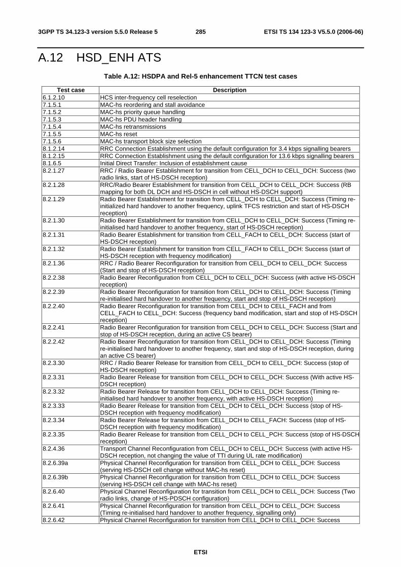
ETSI
ETSI TS 134 123-3 V5.5.0 (2006-06) 2853GPP TS 34.123-3 version 5.5.0 Release 5
A.12 HSD_ENH ATS Table A.12: HSDPA and Rel-5 enhancement TTCN test cases
Test case Description 6.1.2.10 HCS inter-frequency cell reselection 7.1.5.1 MAC-hs reordering and stall avoidance 7.1.5.2 MAC-hs priority queue handling 7.1.5.3 MAC-hs PDU header handling 7.1.5.4 MAC-hs retransmissions 7.1.5.5 MAC-hs reset 7.1.5.6 MAC-hs transport block size selection 8.1.2.14 RRC Connection Establishment using the default configuration for 3.4 kbps signalling bearers 8.1.2.15 RRC Connection Establishment using the default configuration for 13.6 kbps signalling bearers 8.1.6.5 Initial Direct Transfer: Inclusion of establishment cause 8.2.1.27 RRC / Radio Bearer Establishment for transition from CELL_DCH to CELL_DCH: Success (two
radio links, start of HS-DSCH reception) 8.2.1.28 RRC/Radio Bearer Establishment for transition from CELL_DCH to CELL_DCH: Success (RB
mapping for both DL DCH and HS-DSCH in cell without HS-DSCH support) 8.2.1.29 Radio Bearer Establishment for transition from CELL_DCH to CELL_DCH: Success (Timing re-
initialized hard handover to another frequency, uplink TFCS restriction and start of HS-DSCH reception)
8.2.1.30 Radio Bearer Establishment for transition from CELL_DCH to CELL_DCH: Success (Timing re-initialised hard handover to another frequency, start of HS-DSCH reception)
8.2.1.31 Radio Bearer Establishment for transition from CELL_FACH to CELL_DCH: Success (start of HS-DSCH reception)
8.2.1.32 Radio Bearer Establishment for transition from CELL_FACH to CELL_DCH: Success (start of HS-DSCH reception with frequency modification)
8.2.1.36 RRC / Radio Bearer Reconfiguration for transition from CELL_DCH to CELL_DCH: Success (Start and stop of HS-DSCH reception)
8.2.2.38 Radio Bearer Reconfiguration from CELL_DCH to CELL_DCH: Success (with active HS-DSCH reception)
8.2.2.39 Radio Bearer Reconfiguration for transition from CELL_DCH to CELL_DCH: Success (Timing re-initialised hard handover to another frequency, start and stop of HS-DSCH reception)
8.2.2.40 Radio Bearer Reconfiguration for transition from CELL_DCH to CELL_FACH and from CELL_FACH to CELL_DCH: Success (frequency band modification, start and stop of HS-DSCH reception)
8.2.2.41 Radio Bearer Reconfiguration for transition from CELL_DCH to CELL_DCH: Success (Start and stop of HS-DSCH reception, during an active CS bearer)
8.2.2.42 Radio Bearer Reconfiguration for transition from CELL_DCH to CELL_DCH: Success (Timing re-initialised hard handover to another frequency, start and stop of HS-DSCH reception, during an active CS bearer)
8.2.3.30 RRC / Radio Bearer Release for transition from CELL_DCH to CELL_DCH: Success (stop of HS-DSCH reception)
8.2.3.31 Radio Bearer Release for transition from CELL_DCH to CELL_DCH: Success (With active HS-DSCH reception)
8.2.3.32 Radio Bearer Release for transition from CELL_DCH to CELL_DCH: Success (Timing re-initialised hard handover to another frequency, with active HS-DSCH reception)
8.2.3.33 Radio Bearer Release for transition from CELL_DCH to CELL_DCH: Success (stop of HS-DSCH reception with frequency modification)
8.2.3.34 Radio Bearer Release for transition from CELL_DCH to CELL_FACH: Success (stop of HS-DSCH reception with frequency modification)
8.2.3.35 Radio Bearer Release for transition from CELL_DCH to CELL_PCH: Success (stop of HS-DSCH reception)
8.2.4.36 Transport Channel Reconfiguration from CELL_DCH to CELL_DCH: Success (with active HS-DSCH reception, not changing the value of TTI during UL rate modification)
8.2.6.39a Physical Channel Reconfiguration for transition from CELL_DCH to CELL_DCH: Success (serving HS-DSCH cell change without MAC-hs reset)
8.2.6.39b Physical Channel Reconfiguration for transition from CELL_DCH to CELL_DCH: Success (serving HS-DSCH cell change with MAC-hs reset)
8.2.6.40 Physical Channel Reconfiguration for transition from CELL_DCH to CELL_DCH: Success (Two radio links, change of HS-PDSCH configuration)
8.2.6.41 Physical Channel Reconfiguration for transition from CELL_DCH to CELL_DCH: Success (Timing re-initialised hard handover to another frequency, signalling only)
8.2.6.42 Physical Channel Reconfiguration for transition from CELL_DCH to CELL_DCH: Success
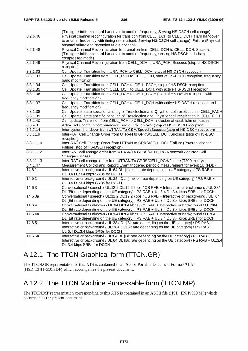
ETSI
ETSI TS 134 123-3 V5.5.0 (2006-06) 2863GPP TS 34.123-3 version 5.5.0 Release 5
(Timing re-initialized hard handover to another frequency, Serving HS-DSCH cell change) 8.2.6.46 Physical channel reconfiguration for transition from CELL_DCH to CELL_DCH (Hard handover
to another frequency with timing re-initialised. Serving HS-DSCH cell change): Failure (Physical channel failure and reversion to old channel)
8.2.6.48 Physical Channel Reconfiguration for transition from CELL_DCH to CELL_DCH: Success (Timing re-initialized hard handover to another frequency, serving HS-DSCH cell change, compressed mode)
8.2.6.49 Physical Channel Reconfiguration from CELL_DCH to URA_PCH: Success (stop of HS-DSCH reception)
8.3.1.32 Cell Update: Transition from URA_PCH to CELL_DCH, start of HS-DSCH reception 8.3.1.33 Cell Update: Transition from CELL_PCH to CELL_DCH, start of HS-DSCH reception, frequency
band modification 8.3.1.34 Cell Update: Transition from CELL_DCH to CELL_FACH, stop of HS-DSCH reception 8.3.1.35 Cell Update: Transition from CELL_DCH to CELL_DCH, with active HS-DSCH reception 8.3.1.36 Cell Update: Transition from CELL_DCH to CELL_FACH (stop of HS-DSCH reception with
frequency modification) 8.3.1.37 Cell Update: Transition from CELL_DCH to CELL_DCH (with active HS-DSCH reception and
frequency modification) 8.3.1.38 Cell Update: state specific handling of Treselection and Qhyst for cell reselection in CELL_FACH8.3.1.39 Cell Update: state specific handling of Treselection and Qhyst for cell reselection in CELL_PCH 8.3.1.40 Cell update: Transition from CELL_PCH to CELL_DCH, inclusion of establishment cause 8.3.4.9 Active set update in soft handover: Radio Link removal (stop of HS-PDSCH reception) 8.3.7.14 Inter system handover from UTRAN/To GSM/Speech/Success (stop of HS-DSCH reception) 8.3.11.9 Inter-RAT Cell Change Order from UTRAN to GPRS/CELL_DCH/Success (stop of HS-DSCH
reception) 8.3.11.10 Inter-RAT Cell Change Order from UTRAN to GPRS/CELL_DCH/Failure (Physical channel
Failure, stop of HS-DSCH reception) 8.3.11.12 Inter-RAT cell change order from UTRAN/To GPRS/CELL_DCH/Network Assisted Cell
Change/Success 8.3.11.13 Inter-RAT cell change order from UTRAN/To GPRS/CELL_DCH/Failure (T309 expiry) 8.4.1.47 Measurement Control and Report: Event triggered periodic measurement for event 1B (FDD) 14.6.1 Interactive or background / UL:64 DL: [max bit rate depending on UE category] / PS RAB +
UL:3.4 DL:3.4 kbps SRBs for DCCH 14.6.2 Interactive or background / UL:384 DL: [max bit rate depending on UE category] / PS RAB +
UL:3.4 DL:3.4 kbps SRBs for DCCH 14.6.3 Conversational / speech / UL:12.2 DL:12.2 kbps / CS RAB + Interactive or background / UL:384
DL:[Bit rate depending on the UE category] / PS RAB + UL:3.4 DL:3.4 kbps SRBs for DCCH 14.6.3a Conversational / speech / UL:12.2 DL:12.2 kbps / CS RAB + Interactive or background / UL: 64
DL:[Bit rate depending on the UE category] / PS RAB + UL:3.4 DL:3.4 kbps SRBs for DCCH 14.6.4 Conversational / unknown / UL:64 DL:64 kbps / CS RAB + Interactive or background / UL:384
DL:[Bit rate depending on the UE category] / PS RAB + UL:3.4 DL:3.4 kbps SRBs for DCCH 14.6.4a Conversational / unknown / UL:64 DL:64 kbps / CS RAB + Interactive or background / UL:64
DL:[Bit rate depending on the UE category] / PS RAB + UL:3.4 DL:3.4 kbps SRBs for DCCH 14.6.5 Interactive or background / UL:384 DL:[Bit rate depending on the UE category] / PS RAB +
Interactive or background / UL:384 DL:[Bit rate depending on the UE category] / PS RAB + UL:3.4 DL:3.4 kbps SRBs for DCCH
14.6.5a Interactive or background / UL:64 DL:[Bit rate depending on the UE category] / PS RAB + Interactive or background / UL:64 DL:[Bit rate depending on the UE category] / PS RAB + UL:3.4 DL:3.4 kbps SRBs for DCCH
A.12.1 The TTCN Graphical form (TTCN.GR) The TTCN.GR representation of this ATS is contained in an Adobe Portable Document Format™ file (HSD_ENHv550.PDF) which accompanies the present document.
A.12.2 The TTCN Machine Processable form (TTCN.MP) The TTCN.MP representation corresponding to this ATS is contained in an ASCII file (HSD_ENHv550.MP) which accompanies the present document.
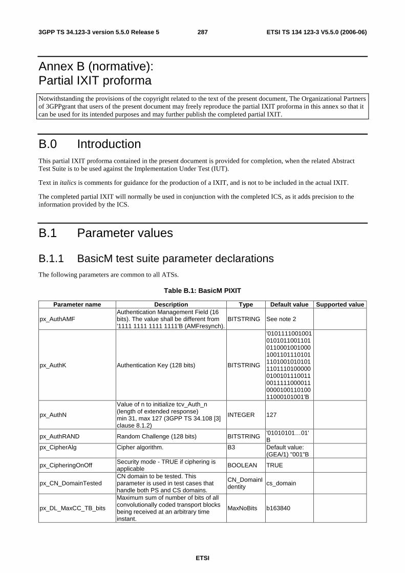
ETSI
ETSI TS 134 123-3 V5.5.0 (2006-06) 2873GPP TS 34.123-3 version 5.5.0 Release 5
Annex B (normative): Partial IXIT proforma Notwithstanding the provisions of the copyright related to the text of the present document, The Organizational Partners of 3GPPgrant that users of the present document may freely reproduce the partial IXIT proforma in this annex so that it can be used for its intended purposes and may further publish the completed partial IXIT.
B.0 Introduction This partial IXIT proforma contained in the present document is provided for completion, when the related Abstract Test Suite is to be used against the Implementation Under Test (IUT).
Text in italics is comments for guidance for the production of a IXIT, and is not to be included in the actual IXIT.
The completed partial IXIT will normally be used in conjunction with the completed ICS, as it adds precision to the information provided by the ICS.
B.1 Parameter values
B.1.1 BasicM test suite parameter declarations The following parameters are common to all ATSs.
Table B.1: BasicM PIXIT
Parameter name Description Type Default value Supported value
px_AuthAMF Authentication Management Field (16 bits). The value shall be different from '1111 1111 1111 1111'B (AMFresynch).
BITSTRING See note 2
px_AuthK Authentication Key (128 bits) BITSTRING
'01011110010010101011001101011000100100010011011101011101001010101110111010000001001011100110011111000011000010011010011000101001'B
px_AuthN
Value of n to initialize tcv_Auth_n (length of extended response) min 31, max 127 (3GPP TS 34.108 [3] clause 8.1.2)
INTEGER 127
px_AuthRAND Random Challenge (128 bits) BITSTRING '01010101…01'B
px_CipherAlg Cipher algorithm. B3 Default value: (GEA/1) "001"B
px_CipheringOnOff Security mode - TRUE if ciphering is applicable BOOLEAN TRUE
px_CN_DomainTested CN domain to be tested. This parameter is used in test cases that handle both PS and CS domains.
CN_DomainIdentity cs_domain
px_DL_MaxCC_TB_bits
Maximum sum of number of bits of all convolutionally coded transport blocks being received at an arbitrary time instant.
MaxNoBits b163840
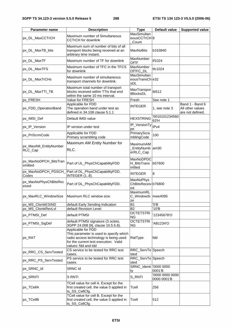
ETSI
ETSI TS 134 123-3 V5.5.0 (2006-06) 2883GPP TS 34.123-3 version 5.5.0 Release 5
Parameter name Description Type Default value Supported value
px_DL_MaxCCTrCH Maximum number of Simultaneous CCTrCH for downlink
MaxSimultaneousCCTrCH_Count
8
px_DL_MaxTB_bits Maximum sum of number of bits of all transport blocks being received at an arbitrary time instant.
MaxNoBits b163840
px_DL_MaxTF Maximum number of TF for downlink MaxNumberOfTF tf1024
px_DL_MaxTFS Maximum number of TFC in the TFCS for downlink
MaxNumberOfTFC_DL
tfc1024
px_DL_MaxTrCHs Maximum number of simultaneous transport channels for downlink.
MaxSimultaneousTransChsDL
e32
px_DL_MaxTTI_TB Maximum total number of transport blocks received within TTIs that end within the same 10 ms interval.
MaxTransportBlocksDL tb512
px_FRESH Value for FRESH Fresh See note 1
px_FDD_OperationBand Applicable for FDD The operation band under test as defined in 34.108 clause 5.1.1
INTEGER 1, see note 3
Band 1 - Band 6 All other values are not defined.
px_IMSI_Def Default IMSI value HEXSTRING '001010123456063'H
px_IP_Version IP version under test IP_VersionType IPv4
px_PriScrmCode Applicable for FDD Primary scrambling code
PrimaryScramblingCode
100
px_MaxAM_EntityNumberRLC_Cap
Maximum AM Entity Number for
RLC.
MaximumAM_EntityNumberRLC_Cap
am30
px_MaxNoDPCH_BitsTransmitted Part of UL_PhysChCapabilityFDD
MaxNoDPDCH_BitsTransmitted
b57600
px_MaxNoDPCH_PDSCH_Codes
Part of DL_PhysChCapabilityFDD. INTEGER (1..8). INTEGER 8
px_MaxNoPhysChBitsReceived
Part of DL_PhysChCapabilityFDD. MaxNoPhysChBitsReceived
b76800
px_MaxRLC_WindowSize Maximum RLC window size. MaximumRLC_WindowSize
mws4095
px_MS_ClsmkESIND default Early Sending Indication B1 '0'B px_MS_ClsmkRevLvl default Revision Level B2 '10'B
px_PTMSI_Def default PTMSI OCTETSTRING '12345678'O
px_PTMSI_SigDef default PTMSI signature (3 octets, 3GPP 24.008 [9], clause 10.5.5.8).
OCTETSTRING 'AB1234'O
px_RAT
Applicable for FDD This parameter is used to specify which radio access technology is being used for the current test execution. Valid values: fdd and tdd
RatType fdd
px_RRC_CS_ServTested CS service to be tested for RRC test cases.
RRC_ServTested
Speech
px_RRC_PS_ServTested PS service to be tested for RRC test cases.
RRC_ServTested
Speech
px_SRNC_Id SRNC Id SRNC_Identity
'0000 0000 0001'B
px_SRNTI S RNTI S_RNTI '0000 0000 0000 0000 0001'B
px_TCellA TCell value for cell A. Except for the first created cell, the value 0 applied in ts_SS_CellCfg.
Tcell 256
px_TCellB TCell value for cell B. Except for the first created cell, the value 0 applied in ts_SS_CellCfg.
Tcell 512

ETSI
ETSI TS 134 123-3 V5.5.0 (2006-06) 2893GPP TS 34.123-3 version 5.5.0 Release 5
Parameter name Description Type Default value Supported value
px_TCellC TCell value for cell C. Except the first created cell, the value 0 applied in ts_SS_CellCfg.
Tcell 1536
px_TCellD TCell value for cell D. Except the first created cell, the value 0 applied in ts_SS_CellCfg.
Tcell 321
px_TCellE TCell value for cell E. Except the first created cell, the value 0 applied in ts_SS_CellCfg.
Tcell 833
px_TCellF TCell value for cell F. Except the first created cell, the value 0 applied in ts_SS_CellCfg.
Tcell 6577
px_TCellG TCell value for cell G. Except the first created cell, the value 0 applied in ts_SS_CellCfg.
Tcell 7253
px_TCellH TCell value for cell H. Except the first created cell, the value 0 applied in ts_SS_CellCfg.
Tcell 4351
px_TimerDequeuePCO Additional time for dequeueing PCO INTEGER 5000 (ms)
px_TMSI_Def Default TMSI OCTETSTRING '12345678'O
px_TotalRLC_AM_BufferSize Total RLC AM buffer size.
TotalRLC_AM_BufferSize
NA
px_UARFCN_D_Mid Applicable for FDD Mid Range downlink UARFCN value INTEGER 10700
px_UARFCN_D_Low Applicable for FDD Low Range downlink UARFCN value INTEGER 10563
px_UARFCN_D_High Applicable for FDD High Range downlink UARFCN value
INTEGER 10837
px_UE_OpModeDef
Default UE operation mode (either opModeA or opModeC). (For most UEs this corresponds class-A or class-C, and can not be changed by the user)
UE_OperationMode opModeA
px_UE_PositioningNetworkAssistedGPS_Sup
UE positioning capability: supports the network assisted GPS
NetworkAssistedGPS_Supported
networkBased
px_UE_PowerClass UE_PowerClass value. UE_PowerClass 1
px_UL_MaxCC_TB_bits
Maximum sum of number of bits of all convolutionally coded transport blocks being transmitted at an arbitrary time instant.
MaxNoBits b163840
px_UL_MaxTB_bits Maximum sum of number of bits of all transport blocks being transmitted at an arbitrary time instant.
MaxNoBits b163840
px_UL_MaxTF Maximum number of TF for uplink. MaxNumberOfTF tf1024
px_UL_MaxTFS Maximum number of TFC in the TFCS for uplink.
MaxNumberOfTFC_DL
tfc1024
px_UL_MaxTrCHs Maximum number of simultaneous transport channels for uplink.
MaxSimultaneousTransChsUL
e32
px_UL_MaxTTI_TB Maximum total number of transport blocks transmitted within TTIs that start at the same time.
MaxTransportBlocksUL tb512
px_UL_ScramblingCode Applicable for FDD UL scrambling code value to be used by UE.
UL_ScramblingCode 0
px_UTRAN_GERAN
This parameter is used to specify for which environment region the system information blocks are broadcast in the test execution. Valid values: "UTRAN only" and "UTRAN and GERAN".
Region
"UTRAN and GERAN"

ETSI
ETSI TS 134 123-3 V5.5.0 (2006-06) 2903GPP TS 34.123-3 version 5.5.0 Release 5
Parameter name Description Type Default value Supported value NOTE 1: No default value can be proposed (Manufacturer defined value). NOTE 2: No default value can be proposed, because not enough information is available in 3GPP TS 34.109 [4]
clause 8.1.2. NOTE 3: This value shall be set in synchronisation with the values that are being set for the 6 other pixits viz:
px_UARFCN_D_High,px_UARFCN_U_High, px_UARFCN_D_Mid,px_UARFCN_L_Mid, px_UARFCN_D_Low, px_UARFCN_U_Low
B.1.2 L3M test suite parameters declarations The following parameters are commonly used in the RRC and NAS ATSs.
Table B.2: L3M PIXIT
Parameter name Description Type Default value Supported value
px_BcapDataCompression Data compression supported (used in the Bearer Capability) B1 '0'B
px_BcapFNUR
Fixed Network User rate supported: '00001'B: FNUR 9.6 kbit/s '00010'B: FNUR 14.4 kbit/s '00011'B: FNUR 19.2 kbit/s '00100'B: FNUR 28.8 kbit/s '00101'B: FNUR 38.4 kbit/s '00110'B: FNUR 48.0 kbit/s '00111'B: FNUR 56.0 kbit/s '01000'B: FNUR 64.0 kbit/s '01001'B: FNUR 33.6 kbit/s '01010'B: FNUR 32.0 kbit/s
B5 '00001'B
px_BcapITC
Information transfer capability supported (used for the generation of the Bearer Capability) 0 - UDI 1 - RDI 2 - 31 kHz Audio 3 - Other
ItcInt 2
px_BcapModemType Modem type supported (used in the Bearer Capability) B5 '00110'B
px_BcapNumberDataBits Number of data bits supported (used in the Bearer Capability)
B1 '1'B
px_BcapNumberStopBits Number of Stops bits supported (used in the Bearer Capability) B1 '1'B
px_BcapOtherModemType Other modem type supported (used in the Bearer Capability) B2 '10'B
px_BcapParity Parity supported (used in the Bearer Capability)
B3 '011'B
px_BcapSACP Signalling access protocol supported (used in the Bearer Capability) B3 '001'B
px_BcapSyncAsync Synchronous '0'B or Asynchronous '1'B mode supported by IUT B1 '1'B
px_BcapUeFlowControl
UE flow control. 0-outband, 1-inband, 2-no flow control. 3- X.25 4- X.75 Default: 0, outband flow control
FlowControl 0
px_CC_CallDiallingDigits Dialling digits used to initiate a CC MO call (used with the AT dial D command).
IA5String "0123456902"
px_CC_Serv
Service selected for Mobile Originated calls and Mobile Terminated calls. The possible values are ("Telephony", "EmergencyCall", "31kHz", "V110", "V120", "PIAFS", "FTM", "X31", "BTM", "MmediaCall")
Services "31kHz"

ETSI
ETSI TS 134 123-3 V5.5.0 (2006-06) 2913GPP TS 34.123-3 version 5.5.0 Release 5
Parameter name Description Type Default value Supported value
px_DeltaSS_DelayTime Tdelta value (refer to 34.108 clause 4.2.3) in ms. INTEGER 55ms
px_EmergencyCallNumber Emergency Number used by UE to initiate an emergency call
EmergencyNumber
"112"
px_IMEI_Def Default IMEI value HEXSTRING See note 1 px_IMEISV_Def Default IMEISV value HEXSTRING See note 1
px_IMSI_Diff Different IMSI from the IMSI stored in the USIM HEXSTRING '0010106543210
63'H
px_SupportOpModeC
TRUE if UE supports operation mode C, i.e. UE offers PS services only (see 3GPP 23.060 clause 4.1 and 3GPP 24.008)
BOOLEAN TRUE
px_NwOrgPDP_Support
This indicates if the UE implementation supports network originated PDP Context. TRUE indicates, supported FALSE indicate, not supported
BOOLEAN FALSE
px_PDP_IP_AddrInfoDCH A string parameter that identifies the MT in the address space applicable to the PDP for DCH.
IA5String "200.1.1.80"
px_PDP_IP_AddrInfoFACH
A string parameter that identifies the MT in the address space applicable to the PDP for FACH.
IA5String "200.1.1.90"
px_PTMSI_2 Second PTMSI used for testing. OCTETSTRING '09876543'O
px_PTMSI_Sig2 Second PTMSI signature used for testing.
OCTETSTRING 'AB1234'O
px_TMSI_2 Second TMSI value for testing OCTETSTRING '09876543'O
px_SMS_IndexOffset SMS index offset for the numbering of short messages, value range: (0,1) INTEGER 0
NOTE 1: No default value can be proposed (Manufacturer defined value).
B.1.3 NAS test suite parameters declarations The following parameters are commonly used in the NAS ATS.
Table B.3: NAS PIXIT
Parameter name Description Type Default value Supported value
px_AuthRAND_2 A second Random Challenge (128 bits)
BITSTRING '1010101…10'B
px_AutocallingBlacklistNumber
Number of B-party numbers that can be stored in the list of blacklisted numbers
INTEGER 20
px_AutocallingCause1or2 Cause value of category 1 or 2 to be used in TC_17_1_3 INTEGER 18
px_AutocallingNumber Called number to be used for auto calling
IA5String "0613454120"
px_AutocallingRepeatCat1or2
Number of repeat attempt done for the category 1 or 2 to be used in TC_17_1_3
INTEGER 10
px_CC_ServNotSupp
Not supported service selected for Mobile Originated calls and Mobile Terminated calls. The possible values are ("Telephony", "EmergencyCall", "31kHz", "V110", "V120", "PIAFS", "FTM", "X31", "BTM", "MmediaCall")
Services "BTM"
px_DTMF_BasicCharSet TRUE if DMTF Chars 0-9, *, # supported BOOLEAN TRUE
px_DTMF_OtherCharSet TRUE if DMTF Chars A, B, C, D supported BOOLEAN TRUE

ETSI
ETSI TS 134 123-3 V5.5.0 (2006-06) 2923GPP TS 34.123-3 version 5.5.0 Release 5
Parameter name Description Type Default value Supported value
px_DTMF_ToneInd TRUE if UE support DTMF tone indication BOOLEAN TRUE
px_PTMSI_Sig3 Second PTMSI signature used for testing
OCTETSTRING
'AB1239'O
px_UuInfo User-user information for TC 10_3 OCTETSTRING '01020304'O
px_Uupd User-user protocol discriminator for TC 10_3 B8 '00000100'B
px_VTS_AT_CommandSupp
TRUE if the AT command +VTS is supported
BOOLEAN TRUE
B.1.4 SMS test suite parameters declarations These parameters are used in the SMS ATS.
Table B.4: SMS PIXIT
Parameter name Description Type Default value Supported value
px_BMC_CB_RepPeriod01 CB repetition period for CB message 1
INTEGER 2
px_BMC_CB_RepPeriod02 CB repetition period for CB message 2 INTEGER 2
px_BMC_NoOfBC_Req01 No of broadcasts requested for CB message 1 INTEGER 2
px_BMC_NoOfBC_Req02 No of broadcasts requested for CB message 2
INTEGER 2
px_MaxCP_DataRetx max. number of CP data retransmissions for SMS INTEGER 3
px_SMS_CB_Data01 Contents of the first Cell Broadcast Message sent will be converted to an OCTETSTRING
IA5String "First Cell Broadcast Message"
px_SMS_CB_Data02 Contents of the second Cell Broadcast Message sent will be converted to an OCTETSTRING
IA5String "Second Cell Broadcast Message"
px_SMS_CB_MsgId01 Message Id to be used for the first Cell Broadcast Message sent B16 '0000000000000
001'B
px_SMS_CB_MsgId02 Message Id to be used for the second Cell Broadcast Message sent B16 '0000000000000
010'B
px_SMS_MsgFrmt SMS Message Format <mode> of TS 27.005 cl. 3.2.3 IA5String "0"
px_SMS_PrefMem1 SMS Preferred Memory 1 <mem1> of TS 27.005 cl. 3.1
IA5String "SM"
px_SMS_PrefMem2 SMS Preferred Memory 2 <mem2> of TS 27.005 cl. 3.1 IA5String "SM"
px_SMS_PrefMem3 SMS Preferred Memory 3 <mem3> of TS 27.005 cl. 3.1 IA5String "MT"
px_SMS_Service SMS Service <service> of TS 27.005 cl. 3.2.1
IA5String "0"
px_TC1M Value for timer TC1M, to be declared by the manufacturer INTEGER 10000
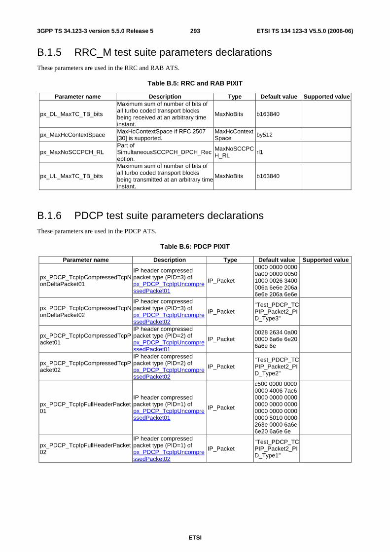
ETSI
ETSI TS 134 123-3 V5.5.0 (2006-06) 2933GPP TS 34.123-3 version 5.5.0 Release 5
B.1.5 RRC_M test suite parameters declarations These parameters are used in the RRC and RAB ATS.
Table B.5: RRC and RAB PIXIT
Parameter name Description Type Default value Supported value
px_DL_MaxTC_TB_bits
Maximum sum of number of bits of all turbo coded transport blocks being received at an arbitrary time instant.
MaxNoBits b163840
px_MaxHcContextSpace MaxHcContextSpace if RFC 2507 [30] is supported.
MaxHcContextSpace by512
px_MaxNoSCCPCH_RL Part of SimultaneousSCCPCH_DPCH_Reception.
MaxNoSCCPCH_RL rl1
px_UL_MaxTC_TB_bits
Maximum sum of number of bits of all turbo coded transport blocks being transmitted at an arbitrary time instant.
MaxNoBits b163840
B.1.6 PDCP test suite parameters declarations These parameters are used in the PDCP ATS.
Table B.6: PDCP PIXIT
Parameter name Description Type Default value Supported value
px_PDCP_TcpIpCompressedTcpNonDeltaPacket01
IP header compressed packet type (PID=3) of px_PDCP_TcpIpUncompressedPacket01
IP_Packet
0000 0000 0000 0a00 0000 0050 1000 0026 3400 006a 6e6e 206a 6e6e 206a 6e6e
px_PDCP_TcpIpCompressedTcpNonDeltaPacket02
IP header compressed packet type (PID=3) of px_PDCP_TcpIpUncompressedPacket02
IP_Packet "Test_PDCP_TCPIP_Packet2_PID_Type3"
px_PDCP_TcpIpCompressedTcpPacket01
IP header compressed packet type (PID=2) of px_PDCP_TcpIpUncompressedPacket01
IP_Packet 0028 2634 0a00 0000 6a6e 6e20 6a6e 6e
px_PDCP_TcpIpCompressedTcpPacket02
IP header compressed packet type (PID=2) of px_PDCP_TcpIpUncompressedPacket02
IP_Packet "Test_PDCP_TCPIP_Packet2_PID_Type2"
px_PDCP_TcpIpFullHeaderPacket01
IP header compressed packet type (PID=1) of px_PDCP_TcpIpUncompressedPacket01
IP_Packet
c500 0000 0000 0000 4006 7ac6 0000 0000 0000 0000 0000 0000 0000 0000 0000 0000 5010 0000 263e 0000 6a6e 6e20 6a6e 6e
px_PDCP_TcpIpFullHeaderPacket02
IP header compressed packet type (PID=1) of px_PDCP_TcpIpUncompressedPacket02
IP_Packet "Test_PDCP_TCPIP_Packet2_PID_Type1"

ETSI
ETSI TS 134 123-3 V5.5.0 (2006-06) 2943GPP TS 34.123-3 version 5.5.0 Release 5
Parameter name Description Type Default value Supported value
px_PDCP_TcpIpUncompressedPacket01
uncompressed TCP/IP Packet01 IP_Packet
4500 0033 0000 0000 4006 7ac6 0000 0000 0000 0000 0000 0000 0000 0000 0000 0000 5010 0000 263e 0000 6a6e 6e20 6a6e 6e
px_PDCP_TcpIpUncompressedPacket02
uncompressed TCP/IP Packet02 IP_Packet "Test_PDCP_TC
PIP_Packet2"
px_PDCP_UdpIpCompressedTcpNonTcpPacket01
IP header compressed packet type (PID=4) of px_PDCP_UdpIpUncompressedPacket01
IP_Packet 0001 0000 763c 6a6e 6e20 6a6e 6e20 6a6e 6e
px_PDCP_UdpIpCompressedTcpNonTcpPacket02
IP header compressed packet type (PID=4) of px_PDCP_UdpIpUncompressedPacket02
IP_Packet "Test_PDCP_UDPIP_Packet2_PID_Type4"
px_PDCP_UdpIpFullHeaderPacket01
IP header compressed packet type (PID=1) of px_PDCP_UdpIpUncompressedPacket01
IP_Packet
8500 0100 0000 0000 4011 7ac7 0000 0000 0000 0000 0000 0000 0013 763c 6a6e 6e20 6a6e 6e20 6a6e 6e
px_PDCP_UdpIpFullHeaderPacket02
IP header compressed packet type (PID=1) of px_PDCP_UdpIpUncompressedPacket02
IP_Packet "Test_PDCP_UDPIP_Packet2_PID_Type1"
px_PDCP_UdpIpUncompressedPacket01
uncompressed UDP/IP Packet01 IP_Packet
4500 0027 0000 0000 4011 7ac7 0000 0000 0000 0000 0000 0000 0013 763c 6a6e 6e20 6a6e 6e20 6a6e 6e
px_PDCP_UdpIpUncompressedPacket02
uncompressed UDP/IP Packet02 IP_Packet "Test_PDCP_U
DPIP_Packet2"
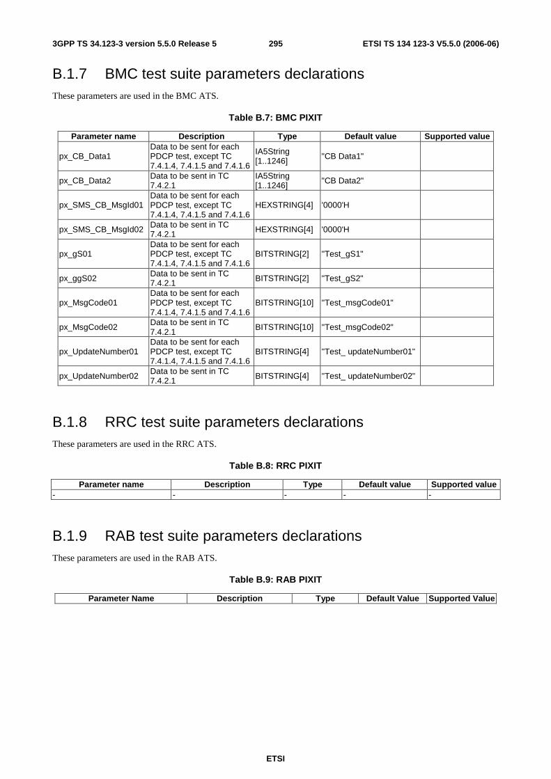
ETSI
ETSI TS 134 123-3 V5.5.0 (2006-06) 2953GPP TS 34.123-3 version 5.5.0 Release 5
B.1.7 BMC test suite parameters declarations These parameters are used in the BMC ATS.
Table B.7: BMC PIXIT
Parameter name Description Type Default value Supported value
px_CB_Data1 Data to be sent for each PDCP test, except TC 7.4.1.4, 7.4.1.5 and 7.4.1.6
IA5String [1..1246] "CB Data1"
px_CB_Data2 Data to be sent in TC 7.4.2.1
IA5String [1..1246] "CB Data2"
px_SMS_CB_MsgId01 Data to be sent for each PDCP test, except TC 7.4.1.4, 7.4.1.5 and 7.4.1.6
HEXSTRING[4] '0000'H
px_SMS_CB_MsgId02 Data to be sent in TC 7.4.2.1 HEXSTRING[4] '0000'H
px_gS01 Data to be sent for each PDCP test, except TC 7.4.1.4, 7.4.1.5 and 7.4.1.6
BITSTRING[2] "Test_gS1"
px_ggS02 Data to be sent in TC 7.4.2.1 BITSTRING[2] "Test_gS2"
px_MsgCode01 Data to be sent for each PDCP test, except TC 7.4.1.4, 7.4.1.5 and 7.4.1.6
BITSTRING[10] "Test_msgCode01"
px_MsgCode02 Data to be sent in TC 7.4.2.1
BITSTRING[10] "Test_msgCode02"
px_UpdateNumber01 Data to be sent for each PDCP test, except TC 7.4.1.4, 7.4.1.5 and 7.4.1.6
BITSTRING[4] "Test_ updateNumber01"
px_UpdateNumber02 Data to be sent in TC 7.4.2.1 BITSTRING[4] "Test_ updateNumber02"
B.1.8 RRC test suite parameters declarations These parameters are used in the RRC ATS.
Table B.8: RRC PIXIT
Parameter name Description Type Default value Supported value - - - - -
B.1.9 RAB test suite parameters declarations These parameters are used in the RAB ATS.
Table B.9: RAB PIXIT
Parameter Name Description Type Default Value Supported Value

ETSI
ETSI TS 134 123-3 V5.5.0 (2006-06) 2963GPP TS 34.123-3 version 5.5.0 Release 5
px_CB_Data1 the operator shall define CBS data as IA5String together with the CB message ID used for transmitting this CB data, which is indicated by the UE after reception in a clear way according to the capabilities stored on the SIM. Furthermore, the operator shall describe the indication on the UE side (e.g. certain CBS traffic information)
IA5String_BMC the CB data range is 1..1246 Octets which refers to a IA5String of 1..1246
px_DSCH_RNTI DSCH RNTI DSCH_RNTI '0000 0000 0000 0010'B
px_SMS_CB_MsgId01 the operator shall define the CB Message ID for the CB data1 used for transmitting this CB data, different to CB-Data 2 IXIT
MsgIdType '000'H
px_gS01 used in the Serial No. of the CB_Data01 given as PIXIT, which differentiates between CBS messages from the same source and type
B2 '00'B
px_MsgCode01 used in the Serial No. of the CB_Data01 given as PIXIT, which is the Geographical Scope indicates the area over which the msg code is unique
MsgCodeType '0000000000'B
px_UpdateNumber01 used in the Serial No. of the CB_Data01 given as PIXIT, which indicates a change of the message content of the same CBS message
B4 '0000'B
px_PowerDSCH transmission power level of DSCH
DL_TxPower
B.1.10 RLC and MAC test suite parameters declarations These parameters are used in the MAC ATS.
Table B.10: RLC & MAC PIXIT
Parameter Name Description Type Default Value Supported Value px_NumOfSegInPagResOrServReq
This Pixit is used in MAC test cases 7.1.1.2, 7.1.1.3, 7.1.1.4, 7.1.1.5 and 7.1.1.8 This indicates the number of RLC segments the Paging Response (CS Domain) or Service Request (PS domain) will be segmented in.
INTEGER 2
px_RLC_SDU_buffering Is used in RLC TC 7.2.3.13, indicating the way to handle RLC SDU data for UL transmission when the transmission window is full
BOOLEAN(TRUE for buffering, FALSE for discard)
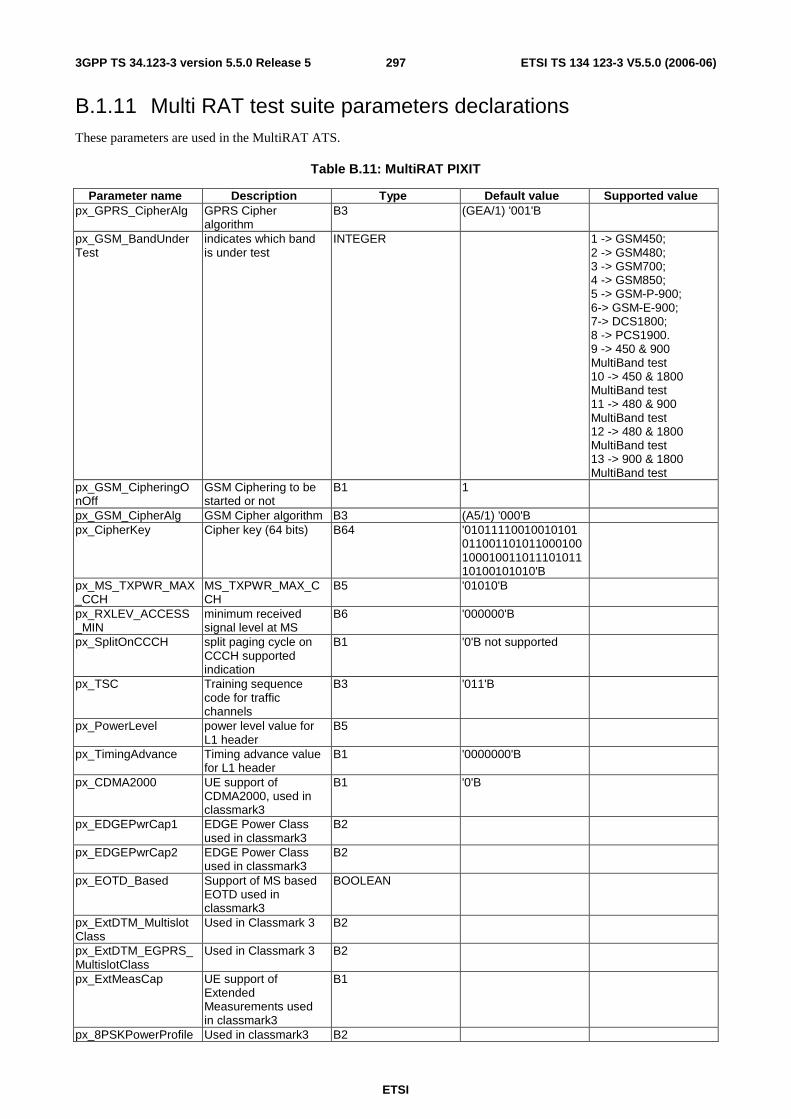
ETSI
ETSI TS 134 123-3 V5.5.0 (2006-06) 2973GPP TS 34.123-3 version 5.5.0 Release 5
B.1.11 Multi RAT test suite parameters declarations These parameters are used in the MultiRAT ATS.
Table B.11: MultiRAT PIXIT
Parameter name Description Type Default value Supported value px_GPRS_CipherAlg GPRS Cipher
algorithm B3 (GEA/1) '001'B
px_GSM_BandUnderTest
indicates which band is under test
INTEGER 1 -> GSM450; 2 -> GSM480; 3 -> GSM700; 4 -> GSM850; 5 -> GSM-P-900; 6-> GSM-E-900; 7-> DCS1800; 8 -> PCS1900. 9 -> 450 & 900 MultiBand test 10 -> 450 & 1800 MultiBand test 11 -> 480 & 900 MultiBand test 12 -> 480 & 1800 MultiBand test 13 -> 900 & 1800 MultiBand test
px_GSM_CipheringOnOff
GSM Ciphering to be started or not
B1 1
px_GSM_CipherAlg GSM Cipher algorithm B3 (A5/1) '000'B px_CipherKey Cipher key (64 bits) B64 '01011110010010101
01100110101100010010001001101110101110100101010'B
px_MS_TXPWR_MAX_CCH
MS_TXPWR_MAX_CCH
B5 '01010'B
px_RXLEV_ACCESS_MIN
minimum received signal level at MS
B6 '000000'B
px_SplitOnCCCH split paging cycle on CCCH supported indication
B1 '0'B not supported
px_TSC Training sequence code for traffic channels
B3 '011'B
px_PowerLevel power level value for L1 header
B5
px_TimingAdvance Timing advance value for L1 header
B1 '0000000'B
px_CDMA2000 UE support of CDMA2000, used in classmark3
B1 '0'B
px_EDGEPwrCap1 EDGE Power Class used in classmark3
B2
px_EDGEPwrCap2 EDGE Power Class used in classmark3
B2
px_EOTD_Based Support of MS based EOTD used in classmark3
BOOLEAN
px_ExtDTM_MultislotClass
Used in Classmark 3 B2
px_ExtDTM_EGPRS_MultislotClass
Used in Classmark 3 B2
px_ExtMeasCap UE support of Extended Measurements used in classmark3
B1
px_8PSKPowerProfile Used in classmark3 B2
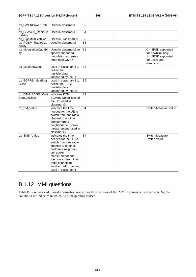
ETSI
ETSI TS 134 123-3 V5.5.0 (2006-06) 2983GPP TS 34.123-3 version 5.5.0 Release 5
px_GMSKPowerProfile
Used in classmark3 B2
px_GSM400_RadioCapability
Used in classmark3 B4
px_HighMultiSlotCap Used in Classmark 3 B2 px_RGSM_RadioCapability
Used in classmark3 B3
px_ModulationCapability
Used in classmark3 to specify supported modulation schemes other than GMSK
B1 0 = 8PSK supported for downlink only, 1 = 8PSK supported for uplink and downlink
px_MultiSlotClass used in classmark3 to define the multislotclass supported by the UE
B5
px_EGPRS_MultiSlotClass
used in classmark3 to define the EDGE multislotclass supported by the UE
B5
px_DTM_EDGE_MultiSlotSubClass
indicates DTM EGPRS capabilities of the UE, used in classmark3
B2
px_SM_Value indicates the time needed for the UE to switch from one radio channel to another and perform a neighbour cell power measurement, used in classmark3
B4 Switch-Measure Value
px_SMS_Value indicates the time needed for the UE to switch from one radio channel to another, perform a neighbour cell power measurement and then switch from that radio channel to another radio channel, used in classmark3
B4 Switch-Measure-Switch Value
B.1.12 MMI questions Table B.12 requests additional information needed for the execution of the MMI commands used in the ATSs, the column 'ATS' indicates in which ATS the question is used.
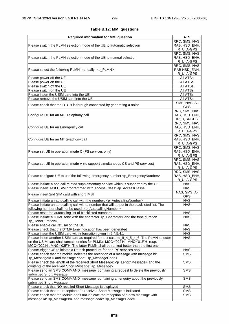
ETSI
ETSI TS 134 123-3 V5.5.0 (2006-06) 2993GPP TS 34.123-3 version 5.5.0 Release 5
Table B.12: MMI questions
Required information for MMI question ATS
Please switch the PLMN selection mode of the UE to automatic selection RRC, SMS, NAS, RAB, HSD_ENH,
IR_U, A-GPS
Please switch the PLMN selection mode of the UE to manual selection RRC, SMS, NAS, RAB, HSD_ENH,
IR_U, A-GPS
Please select the following PLMN manually: <p_PLMN> RRC, SMS, NAS, RAB HSD_ENH,
IR_U, A-GPS Please power off the UE All ATSs Please power on the UE All ATSs Please switch off the UE All ATSs Please switch on the UE All ATSs Please insert the USIM card into the UE All ATSs Please remove the USIM card into the UE All ATSs
Please check that the DTCH is through connected by generating a noise SMS, NAS, A-GPS
Configure UE for an MO Telephony call RRC, SMS, NAS, RAB, HSD_ENH,
IR_U, A-GPS
Configure UE for an Emergency call RRC, SMS, NAS, RAB, HSD_ENH,
IR_U, A-GPS
Configure UE for an MT telephony call RRC, SMS, NAS, RAB, HSD_ENH,
IR_U, A-GPS
Please set UE in operation mode C (PS services only) RRC, SMS, NAS, RAB, HSD_ENH,
IR_U, A-GPS
Please set UE in operation mode A (to support simultaneous CS and PS services) RRC, SMS, NAS, RAB, HSD_ENH,
IR_U, A-GPS
Please configure UE to use the following emergency number <p_EmergencyNumber> RRC, SMS, NAS, RAB, HSD_ENH,
IR_U, A-GPS Please initiate a non call related supplementary service which is supported by the UE NAS Please insert Test USIM programmed with Access Class: <p_AccessClass> NAS
Please insert 2nd SIM card with short IMSI NAS, SMS, A-GPS
Please initiate an autocalling call with the number: <p_AutocallingNumber> NAS Please initiate an autocalling call with a number that will be put in the blacklisted list. The following number shall not be used: <p_AutocallingNumber>
NAS
Please reset the autocalling list of blacklisted numbers NAS Please initiate a DTMF tone with the character <p_Character> and the tone duration <p_ToneDuration>
NAS
Please enable call refusal on the UE NAS Please check that the DTMF tone indication has been generated NAS Please insert the USIM card with information given in 9.4.5.4.1 NAS Please insert another USIM card as required for test case tc_9_4_5_4_6. The PLMN selector on the USIM card shall contain entries for PLMNs MCC='022'H , MNC='01F'H resp. MCC='022'H , MNC='03F'H. The latter PLMN shall be ranked better than the first one
NAS
Please trigger UE to initiate a Detach procedure for non-PS services only NAS Please check that the mobile indicates the reception of a message with message id: <p_MessageId > and message code: <p_MessageCode>
SMS
Please check the length of the received Short Message: <p_LengthMessage> and the contents of the received Short Message: <p_Message>
SMS
Please send an SMS COMMAND message containing a request to delete the previously submitted Short Message
SMS
Please send an SMS COMMAND message containing an enquiry about the previously submitted Short Message
SMS
Please check that NO recalled Short Message is displayed SMS Please check that the reception of a received Short Message is indicated SMS Please check that the Mobile does not indicate the reception of a new message with message id: <p_MessageId> and message code: <p_MessageCode>
SMS

ETSI
ETSI TS 134 123-3 V5.5.0 (2006-06) 3003GPP TS 34.123-3 version 5.5.0 Release 5
Please check that NO reception of a received Short Message of type 0 is indicated SMS Please insert the USIM card of type B into the UE MAC Please insert the USIM card, with information given in 6.1.1.4 RRC Please check that the UE display the registered PLMN as PLMN <p_PLMN> RRC Please insert the USIM card, with information given in 6.1.2.6 RRC Please insert the USIM card, with Type A EFACC RRC Please insert the USIM card, with Type B EFACC RRC Please trigger UE to send three SNDCP PDUs of 500 bytes each on SAPI 11 IR_G Please trigger PDP Context Activation Type 2 in UE IR_G Please trigger MO-LR for position estimate AGPS Please trigger MO-LR for assistance data AGPS Please trigger MO-LR for transfer to 3rd party AGPS Please check that the UE displays the correct information about the LCS client AGPS Please accept the location request within 20 s AGPS Please deny the location request within 20 s AGPS Please do not reply to the location request AGPS Please check that the UE notifies the user of the location request AGPS If the UE does not support the RESET command defined in 34.109, please ensure that the UE has no assistance data stored before running this test case
AGPS
Please trigger UE to send 10 kbytes of data on SAPI 3 IR_G Please trigger UE to send 1 kbyte of data on SAPI 3 IR_G
B.1.13 A-GPS test suite parameters declarations These parameters are used in the A-GPS ATS.
Table B.13: A-GPS PIXIT
Parameter Name Description Type Default Value Supported Value
px_GpsScenario
Pre-defined GPS scenario to be loaded by the upper tester in the Satellite Simulator. See 34.108, 10.7. Minimum value:0, Maximum value: 31
GpsScenarioType 0
px_GeoInfo
Geographical information to be sent as Location Estimate in FACILITY message from the System Simulator.
Ext_GeographicalInformation
9032B9D66360B600323C3C006544
px_LcsClientAddress LCS Client external address ISDN_AddressString
0791534850020200
px_LcsClientName LCS Client name NameString 4551494348
B.1.14 HSD_ENH test suite parameters declarations These parameters are used in the HSD_ENH ATS.
Table B.14: HSD_ENH PIXIT
Parameter Name Description Type Default Value Supported Value px_GERANIu_RadioAccessCapability
MS GERAN Iu mode Radio Access Capability BITSTRING
px_RAB_HS_Exec64_384Supp Set to TRUE if 384kbps is supported and if tests on 64kbps shall be executed
BOOLEAN TRUE

ETSI
ETSI TS 134 123-3 V5.5.0 (2006-06) 3013GPP TS 34.123-3 version 5.5.0 Release 5
Annex C (informative): Additional information to IXIT Notwithstanding the provisions of the copyright related to the text of the present document, The Organizational Partners of 3GPP grant that users of the present document may freely reproduce the IXIT proforma in this annex so that it can be used for its intended purposes and may further publish the completed IXIT.
Additional information may be provided when completing the IXIT questions listed in annex A.
C.1 Identification Summary Table C.1 is completed by the test laboratory. The item "Contract References" is optional.
Table C.1: Identification Summary
IXIT Reference Number Test Laboratory Name Date of Issue Issued to (name of client) Contract References
C.2 Abstract Test Suite Summary In table C.2 the test laboratory provides the version number of the protocol specification and the version number of ATS which are used in the conformance testing.
Table C.2: ATS Summary
Protocol Specification 3GPP TS 25.331 Version of Protocol Specification Test Specification in prose 3GPP TS 34.123-1 Version of TSS & TP Specification ATS Specification 3GPP TS 34.123-3 Version of ATS Specification Abstract Test Method Distributed Test Method
C.3 Test Laboratory
C.3.1 Test Laboratory Identification The test laboratory provides the following information.
ETSI
ETSI TS 134 123-3 V5.5.0 (2006-06) 3023GPP TS 34.123-3 version 5.5.0 Release 5
Table C.3: Test Laboratory Identification
Name of Test Laboratory Postal Address
Office address
e-mail address Telephone Number FAX Number
C.3.2 Accreditation status of the test service The test laboratory provides the following information.
Table C.4: Accreditation status of the test service
Accreditation status Accreditation Reference
C.3.3 Manager of Test Laboratory The test laboratory provides the information about the manager of test laboratory in table C.5.
Table C.5: Manager of Test Laboratory
Name of Manager of Test Laboratory e-mail address Telephone Number FAX Number E-mail Address
C.3.4 Contact person of Test Laboratory The test laboratory provides the information about the contact person of test laboratory in table C.6.
Table C.6: Contact person of Test Laboratory
Name of Contact of Test Laboratory e-mail address Telephone Number FAX Number E-mail Address
C.3.5 Means of Testing In table C.7, the test laboratory provides a statement of conformance of the Means Of Testing (MOT) to the reference standardized ATS, and identifies all restrictions for the test execution required by the MOT beyond those stated in the reference standardized ATS.
ETSI
ETSI TS 134 123-3 V5.5.0 (2006-06) 3033GPP TS 34.123-3 version 5.5.0 Release 5
Table C.7: Means of Testing
Means of Testing
C.3.6 Instructions for Completion In table C.8, the test laboratory provides any specific instructions necessary for completion and return of the proforma from the client.
Table C.8: Instruction for Completion
Instructions for Completion

ETSI
ETSI TS 134 123-3 V5.5.0 (2006-06) 3043GPP TS 34.123-3 version 5.5.0 Release 5
C.4 Client
C.4.1 Client Identification The client provides the identification in table C.9.
Table C.9: Client Identification
Name of Client Postal Address Office Address Telephone Number FAX Number
C.4.2 Client Test Manager In table C.10 the client provides information about the test manager.
Table C.10: Client Test Manager
Name of Client Test Manager Telephone Number FAX Number E-mail Address
C.4.3 Client Contact person In table C.11 the client provides information about the test contact person.
Table C.11: Client Contact person
Name of Client contact person Telephone Number FAX Number E-mail Address
C.4.4 Test Facilities Required In table C.12, the client records the particular facilities required for testing, if a range of facilities is provided by the test laboratory.
ETSI
ETSI TS 134 123-3 V5.5.0 (2006-06) 3053GPP TS 34.123-3 version 5.5.0 Release 5
Table C.12: Test Facilities Required
Test Facilities Required
C.5 System Under Test
C.5.1 SUT Information The client provides information about the SUT in table C.13.
Table C.13: SUT Information
System Name System Version SCS Reference Machine Configuration Operating System Identification IUT Identification ICS Reference for the IUT
C.5.2 Limitations of the SUT In table C.14, the client provides information explaining if any of the abstract tests cannot be executed.
ETSI
ETSI TS 134 123-3 V5.5.0 (2006-06) 3063GPP TS 34.123-3 version 5.5.0 Release 5
Table C.14: Limitation of the SUT
Limitations of the SUT
C.5.3 Environmental Conditions In table C.15 the client provides information about any tighter environmental conditions for the correct operation of the SUT.
Table C.15: Environmental Conditions
Environmental Conditions

ETSI
ETSI TS 134 123-3 V5.5.0 (2006-06) 3073GPP TS 34.123-3 version 5.5.0 Release 5
C.6 Ancillary Protocols This clause is completed by the client in conjunction with the test laboratory.
In the following tables, the client identifies relevant information concerning each ancillary protocol in the SUT other than the IUT itself. One table for one ancillary protocol.
Based on the MOT the test laboratory should create question proforma for each ancillary protocol in the blank space following each table. The information required is dependent on the MOT and the SUT, and covers all the addressing, parameter values, timer values and facilities (relevant to ENs) as defined by the ICS for the ancillary protocol.
C.6.1 Ancillary Protocols 1
Table C.16: Ancillary Protocol 1
Protocol Name Version number ICS Reference (optional) IXIT Reference (optional) PCTR Reference (optional)
C.6.2 Ancillary Protocols 2
Table C.17: Ancillary Protocol 2
Protocol Name Version number ICS Reference (optional) IXIT Reference (optional) PCTR Reference (optional)
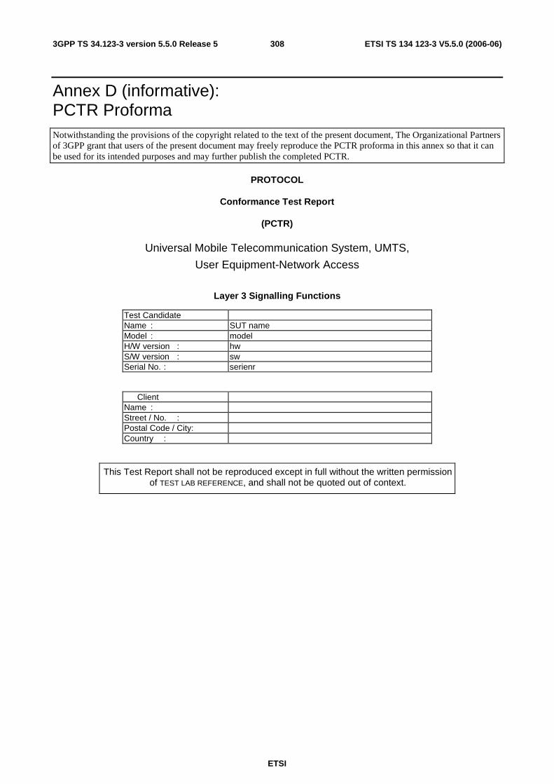
ETSI
ETSI TS 134 123-3 V5.5.0 (2006-06) 3083GPP TS 34.123-3 version 5.5.0 Release 5
Annex D (informative): PCTR Proforma Notwithstanding the provisions of the copyright related to the text of the present document, The Organizational Partners of 3GPP grant that users of the present document may freely reproduce the PCTR proforma in this annex so that it can be used for its intended purposes and may further publish the completed PCTR.
PROTOCOL
Conformance Test Report
(PCTR)
Universal Mobile Telecommunication System, UMTS,
User Equipment-Network Access
Layer 3 Signalling Functions
Test Candidate Name : SUT name Model : model H/W version : hw S/W version : sw Serial No. : serienr
Client Name : Street / No. : Postal Code / City: Country :
This Test Report shall not be reproduced except in full without the written permission of TEST LAB REFERENCE, and shall not be quoted out of context.

ETSI
ETSI TS 134 123-3 V5.5.0 (2006-06) 3093GPP TS 34.123-3 version 5.5.0 Release 5
Annex E (informative): TTCN style guide for 3GPP ATS
E.1 Introduction This annex provides a set of coding standards and development guidelines for use in the development of TTCN abstract test suites for ensuring that user equipment for the 3GPP standard conforms to the relevant core specifications.
The following items are assumed to exist, but their specification is outside the scope of this annex.
- A complete unambiguous prose detailing all test cases to be implemented.
- A complete unambiguous set of core specifications.
- A complete unambiguous detailed description of all the messages that are to be sent.
- A tool or human process that can convert Test Suite Operation Definitions to physical processes within the test system or unit under test.
- An abstracted or generic application programmers interface to all hardware components in the system.
- A tool for the translation and/or compilation of ISO/IEC 9646 [41] series TTCN to run on a test platform.
It is recognized within the context of the 3GPP User Terminal that some of these items are not yet stabilized.
The structure of the present annex maps directly to the guidelines provided in ETR 141 [37]. Rules are repeated in the present annex for convenience, with additional information specific to 3GPP test suite development provided where relevant. For more detailed information or examples about the rules, see ETR 141 [37].
In the present annex, the terms 'should' and 'shall' are frequently used. For the purpose of this annex, the following definitions apply:
- Shall means that the rule must be adhered to for all ATS development. If a rule expressed in terms of 'shall' is not followed, either the ATS must be updated so that the rule is followed, or the rule in the coding conventions must be updated to resolve the difference.
- Should means that the rule is a guideline. If a rule expressed in terms of 'should' is broken, a brief comment should be provided describing why the guideline does not apply.
E.2 ETR 141 rules and applicability RULE 1: Statement of naming conventions
Naming conventions should be explicitly stated. Naming conventions should not exist only for a single ATS, and the reader of an ATS should not be forced to "derive" the rules implicitly. The naming conventions should be part of the ATS conventions contained in the ATS specification document.
Names used in the present annex are comprised of a prefix part and a name body part. Conventions for deriving prefixes and name bodies are described after Rule 3 in the present annex.

ETSI
ETSI TS 134 123-3 V5.5.0 (2006-06) 3103GPP TS 34.123-3 version 5.5.0 Release 5
RULE 2: Coverage of naming conventions Naming conventions stated should, as a minimum, cover the following TTCN objects: - test suite parameters/constants/variables; - test case variables; - formal parameters; - timers; - PDU/ASP/structured types; - PDU/ASP/structured types constraints; - test suite operations; - aliases; - test case/test step identifiers.
RULE 3: General properties of naming conventions a) Protocol standard aligned When there is a relationship between objects defined in the ATS and objects defined in the protocol standard, e.g. PDU types, the same names should be used in the ATS if this does not conflict with the character set for TTCN identifiers or with other rules. In case of a conflict, similar names should be used. b) Distinguishing The naming conventions should be defined in such a way, that objects of different types appearing in the same context, e.g. as constraint values, can be easily distinguished. c) Structured When objects of a given type allow a grouping or structuring into different classes, the names of these objects should reflect the structuring, i.e. the names should be composed of 2 or more parts, indicating the particular structure elements. d) Self-explaining The names should be such that the reader can understand the meaning (type/value/contents) of an object in a given context. When suffixes composed of digits are used, it is normally useful to have some rule expressed explaining the meaning of the digits. e) Consistent The rules stated should be used consistently throughout the document, there should be no exceptions. f) Appropriate name length Following the above rules extensively may occasionally lead to very long names, especially when structuring is used. The names should still be easily readable. When TTCN graphical form (TTCN.GR) is used, very long names are very inconvenient. NOTE: Also, test tools may not be able to implement very long identifier names, which is an important aspect in this
context.
E.2.1 Multiple words are separated by upper case letters at the start of each word
Many names consist of more words, and it shall be easy to distinguish the different words building up the same name. For all TTCN Object classes this is done using the case of the letters.
This rule is mandatory for all names appearing in the body of a dynamic behaviour table, and is recommended for all other TTCN object classes.
Generally every word a name consists of shall start with an upper case letter and the rest of this word shall be in lower case letters.
- E.g.: "channel" + "description" -> "ChannelDescription".
This rule also applies if a word starts after another upper case letter.
- E.g.:. "px" + "Cell" + "A" + "Cell" + "Id" -> px_CellACellId.
This rule also applies if the name has a prefix, which is always lower case.
- E.g.: A test case variable "sequence" + "number" -> tcv_SequenceNumber.
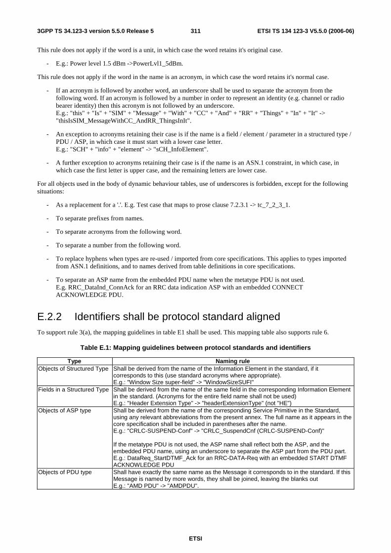
ETSI
ETSI TS 134 123-3 V5.5.0 (2006-06) 3113GPP TS 34.123-3 version 5.5.0 Release 5
This rule does not apply if the word is a unit, in which case the word retains it's original case.
- E.g.: Power level 1.5 dBm ->PowerLvl1_5dBm.
This rule does not apply if the word in the name is an acronym, in which case the word retains it's normal case.
- If an acronym is followed by another word, an underscore shall be used to separate the acronym from the following word. If an acronym is followed by a number in order to represent an identity (e.g. channel or radio bearer identity) then this acronym is not followed by an underscore. E.g.: "this" + "Is" + "SIM" + "Message" + "With" + "CC" + "And" + "RR" + "Things" + "In" + "It" -> "thisIsSIM_MessageWithCC_AndRR_ThingsInIt".
- An exception to acronyms retaining their case is if the name is a field / element / parameter in a structured type / PDU / ASP, in which case it must start with a lower case letter. E.g.: "SCH" + "info" + "element" -> "sCH_InfoElement".
- A further exception to acronyms retaining their case is if the name is an ASN.1 constraint, in which case, in which case the first letter is upper case, and the remaining letters are lower case.
For all objects used in the body of dynamic behaviour tables, use of underscores is forbidden, except for the following situations:
- As a replacement for a '.'. E.g. Test case that maps to prose clause 7.2.3.1 -> tc_7_2_3_1.
- To separate prefixes from names.
- To separate acronyms from the following word.
- To separate a number from the following word.
- To replace hyphens when types are re-used / imported from core specifications. This applies to types imported from ASN.1 definitions, and to names derived from table definitions in core specifications.
- To separate an ASP name from the embedded PDU name when the metatype PDU is not used. E.g. RRC_DataInd_ConnAck for an RRC data indication ASP with an embedded CONNECT ACKNOWLEDGE PDU.
E.2.2 Identifiers shall be protocol standard aligned To support rule 3(a), the mapping guidelines in table E1 shall be used. This mapping table also supports rule 6.
Table E.1: Mapping guidelines between protocol standards and identifiers
Type Naming rule Objects of Structured Type Shall be derived from the name of the Information Element in the standard, if it
corresponds to this (use standard acronyms where appropriate). E.g.: "Window Size super-field" -> "WindowSizeSUFI"
Fields in a Structured Type Shall be derived from the name of the same field in the corresponding Information Element in the standard. (Acronyms for the entire field name shall not be used) E.g.: "Header Extension Type" -> "headerExtensionType" (not "HE")
Objects of ASP type Shall be derived from the name of the corresponding Service Primitive in the Standard, using any relevant abbreviations from the present annex. The full name as it appears in the core specification shall be included in parentheses after the name. E.g.: "CRLC-SUSPEND-Conf" -> "CRLC_SuspendCnf (CRLC-SUSPEND-Conf)" If the metatype PDU is not used, the ASP name shall reflect both the ASP, and the embedded PDU name, using an underscore to separate the ASP part from the PDU part. E.g.: DataReq_StartDTMF_Ack for an RRC-DATA-Req with an embedded START DTMF ACKNOWLEDGE PDU
Objects of PDU type Shall have exactly the same name as the Message it corresponds to in the standard. If this Message is named by more words, they shall be joined, leaving the blanks out E.g.: "AMD PDU" -> "AMDPDU".

ETSI
ETSI TS 134 123-3 V5.5.0 (2006-06) 3123GPP TS 34.123-3 version 5.5.0 Release 5
E.2.3 Identifiers shall be distinguishing (use of prefixes) To support rules 2, 3(b), 4, and 5, the prefixes shown in table E2 shall be used for TTCN objects. Prefixes are separated from the name by an underscore to improve readability by clearly separating the prefix from the name. This convention will also support searching operations. For example, a search for all uses of PIXIT parameters in the test suite is possible by searching for 'px_'.
The optional <protocol> part shall be included in the name when the object is closely related to the protocol (e.g. PICS, some PIXIT parameters), it is necessary to be unambiguous or improves comprehension significantly (e.g. no need to think about protocol stacks on all used interfaces during reading). The optional <protocol> part shall be used for types defined in common modules.
Table E.2: Prefixes used for TTCN objects
TTCN object Case of first character
Prefix Comment
Test Suite Upper - TTCN Module Upper - Simple Type Upper [<protocol>_] Note 8 Structured Type Upper [<protocol>_] Note 8 Element in Structured Type Lower - ASN.1 Type Upper [<protocol>_] Note 8 Element in ASN.1 Type Lower - Test Suite Operation Upper o_[<protocol>_] Notes 1 and 8 TSO Procedural Definition Upper o_[<protocol>_] Notes 1 and 8 Formal Parameter to TSO or TSOP Upper p_ Test Suite Parameter (PICS) Upper pc_[<protocol>_] Note 8 Test Suite Parameter (PIXIT) Upper px_[<protocol>_] Note 8 Test Case Selection Expression Upper [<protocol>_] Note 8 Test Suite Constant Upper tsc_[<protocol>_] Note 8 Test Suite Variable Upper tsv_[<protocol>_] Note 8 Test Case Variable Upper tcv_[<protocol>_] Note 8 PCO Type Upper - PCO Upper - Note 2 CP Upper cp_ Note 2 Timer Upper t_[<protocol>_] Note 8 Test Component Upper mtc_[<protocol>_] or ptc_[<protocol>_] Notes 3 and 8 Test Component Configuration Upper - ASP Type Upper [<protocol>_] Notes 4 and 8 Parameters within ASP Type Lower - Note 4 PDU Type Upper [<protocol>_] Notes 4 and 8
TTCN object Case of first character
Prefix Comment
Fields within PDU Type Lower - Note 4 Encoding Definition Upper enc_ Encoding Variation Upper var_ Invalid Field Encoding Variation Upper inv_ CM Type Upper cm_ Field within CM Type Lower - Alias Upper a_ ASP constraint Upper ca[b|d][s|r|w]_[<protocol>_] Notes 5 and 8 PDU constraints Upper c[b|d][s|r|w]_[<protocol>|AA|108] Notes 5, 8 and 10 Constraint (other types) Upper c[b|d][s|r|w]_[<protocol>_] Notes 5 and 8 Formal Parameter for a Constraint Upper p_ Test Case Group Upper <protocol>/ Note 8 Test Step Group Upper Test Case Upper tc_ Note 6 Test Step Upper (ts_|pr_|po_)<CN domain>_<protocol>_ Notes 7, 8 and 9 Local tree Upper lt_ Defaults Upper <protocol>_ Note 8 NOTE 1: Coding rules are not specified for test suite operation procedural definitions at this stage. These rules will be
defined when the need arises NOTE 2: A prefix is not used for PCO declarations, but is used for CP declarations. This is because PCOs and CPs
will only be used in send and receive statements, and PCOs will be used more frequently than CPs. Since a PCO name or a CP name will be used on most behaviour lines, PCO names should be as short as possible
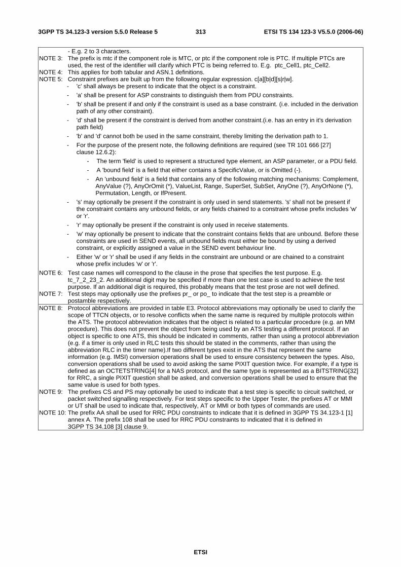
ETSI
ETSI TS 134 123-3 V5.5.0 (2006-06) 3133GPP TS 34.123-3 version 5.5.0 Release 5
- E.g. 2 to 3 characters. NOTE 3: The prefix is mtc if the component role is MTC, or ptc if the component role is PTC. If multiple PTCs are
used, the rest of the identifier will clarify which PTC is being referred to. E.g. ptc_Cell1, ptc_Cell2. NOTE 4: This applies for both tabular and ASN.1 definitions. NOTE 5: Constraint prefixes are built up from the following regular expression. c[a][b|d][s|r|w].
- 'c' shall always be present to indicate that the object is a constraint.
- 'a' shall be present for ASP constraints to distinguish them from PDU constraints.
- 'b' shall be present if and only if the constraint is used as a base constraint. (i.e. included in the derivation path of any other constraint).
- 'd' shall be present if the constraint is derived from another constraint.(i.e. has an entry in it's derivation path field)
- 'b' and 'd' cannot both be used in the same constraint, thereby limiting the derivation path to 1.
- For the purpose of the present note, the following definitions are required (see TR 101 666 [27] clause 12.6.2):
- The term 'field' is used to represent a structured type element, an ASP parameter, or a PDU field.
- A 'bound field' is a field that either contains a SpecificValue, or is Omitted (-).
- An 'unbound field' is a field that contains any of the following matching mechanisms: Complement, AnyValue (?), AnyOrOmit (*), ValueList, Range, SuperSet, SubSet, AnyOne (?), AnyOrNone (*), Permutation, Length, or IfPresent.
- 's' may optionally be present if the constraint is only used in send statements. 's' shall not be present if the constraint contains any unbound fields, or any fields chained to a constraint whose prefix includes 'w' or 'r'.
- 'r' may optionally be present if the constraint is only used in receive statements.
- 'w' may optionally be present to indicate that the constraint contains fields that are unbound. Before these constraints are used in SEND events, all unbound fields must either be bound by using a derived constraint, or explicitly assigned a value in the SEND event behaviour line.
- Either 'w' or 'r' shall be used if any fields in the constraint are unbound or are chained to a constraint whose prefix includes 'w' or 'r'.
NOTE 6: Test case names will correspond to the clause in the prose that specifies the test purpose. E.g. tc_7_2_23_2. An additional digit may be specified if more than one test case is used to achieve the test purpose. If an additional digit is required, this probably means that the test prose are not well defined.
NOTE 7: Test steps may optionally use the prefixes pr_ or po_ to indicate that the test step is a preamble or postamble respectively.
NOTE 8: Protocol abbreviations are provided in table E3. Protocol abbreviations may optionally be used to clarify the scope of TTCN objects, or to resolve conflicts when the same name is required by multiple protocols within the ATS. The protocol abbreviation indicates that the object is related to a particular procedure (e.g. an MM procedure). This does not prevent the object from being used by an ATS testing a different protocol. If an object is specific to one ATS, this should be indicated in comments, rather than using a protocol abbreviation (e.g. if a timer is only used in RLC tests this should be stated in the comments, rather than using the abbreviation RLC in the timer name).If two different types exist in the ATS that represent the same information (e.g. IMSI) conversion operations shall be used to ensure consistency between the types. Also, conversion operations shall be used to avoid asking the same PIXIT question twice. For example, if a type is defined as an OCTETSTRING[4] for a NAS protocol, and the same type is represented as a BITSTRING[32] for RRC, a single PIXIT question shall be asked, and conversion operations shall be used to ensure that the same value is used for both types.
NOTE 9: The prefixes CS and PS may optionally be used to indicate that a test step is specific to circuit switched, or packet switched signalling respectively. For test steps specific to the Upper Tester, the prefixes AT or MMI or UT shall be used to indicate that, respectively, AT or MMI or both types of commands are used.
NOTE 10: The prefix AA shall be used for RRC PDU constraints to indicate that it is defined in 3GPP TS 34.123-1 [1] annex A. The prefix 108 shall be used for RRC PDU constraints to indicated that it is defined in 3GPP TS 34.108 [3] clause 9.
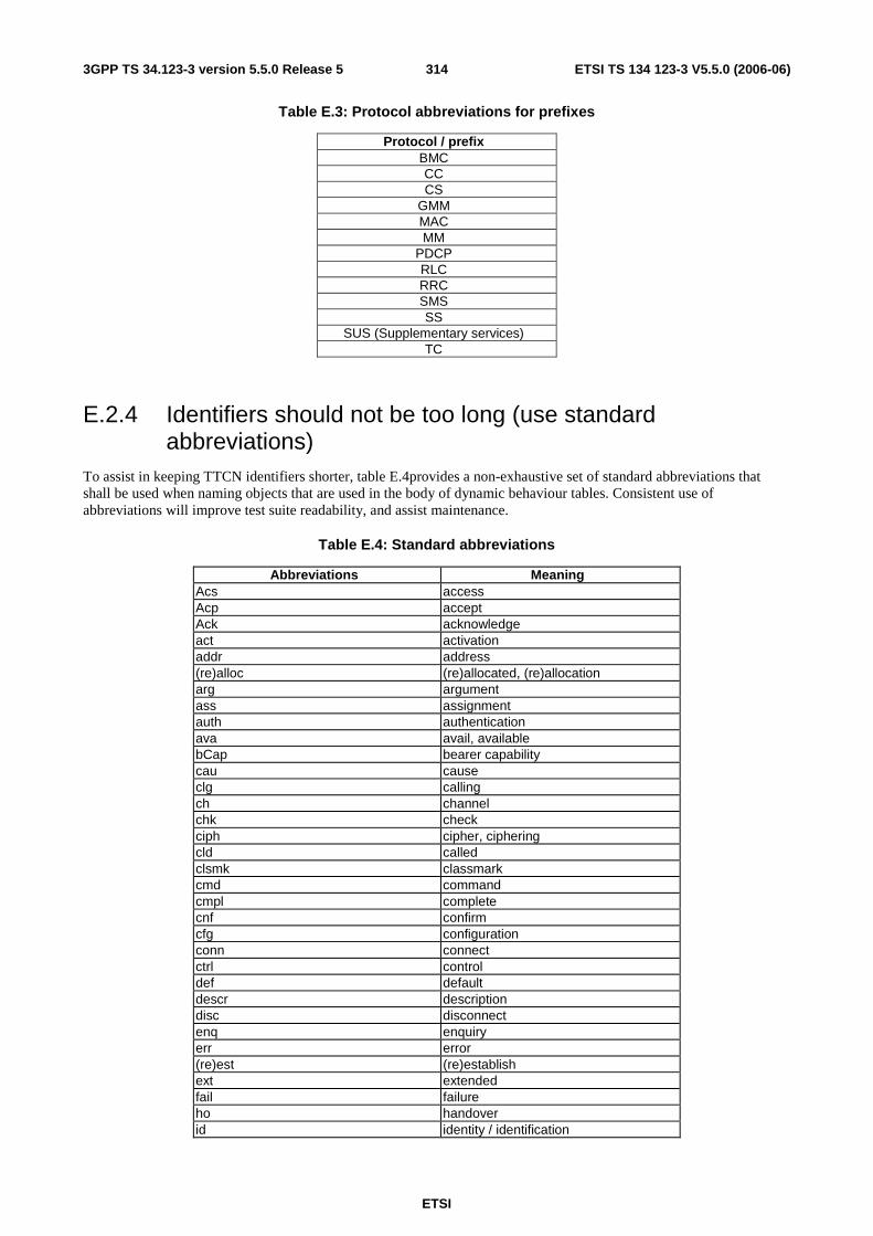
ETSI
ETSI TS 134 123-3 V5.5.0 (2006-06) 3143GPP TS 34.123-3 version 5.5.0 Release 5
Table E.3: Protocol abbreviations for prefixes
Protocol / prefix BMC CC CS
GMM MAC MM
PDCP RLC RRC SMS SS
SUS (Supplementary services) TC
E.2.4 Identifiers should not be too long (use standard abbreviations)
To assist in keeping TTCN identifiers shorter, table E.4provides a non-exhaustive set of standard abbreviations that shall be used when naming objects that are used in the body of dynamic behaviour tables. Consistent use of abbreviations will improve test suite readability, and assist maintenance.
Table E.4: Standard abbreviations
Abbreviations Meaning Acs access Acp accept Ack acknowledge act activation addr address (re)alloc (re)allocated, (re)allocation arg argument ass assignment auth authentication ava avail, available bCap bearer capability cau cause clg calling ch channel chk check ciph cipher, ciphering cld called clsmk classmark cmd command cmpl complete cnf confirm cfg configuration conn connect ctrl control def default descr description disc disconnect enq enquiry err error (re)est (re)establish ext extended fail failure ho handover id identity / identification
ETSI
ETSI TS 134 123-3 V5.5.0 (2006-06) 3153GPP TS 34.123-3 version 5.5.0 Release 5
Abbreviations Meaning ie information element iel information element length ind indication info information init initialize lvl level loc location locUpd location update max maximum mgmt management min minimum misc miscellaneous mod modification ms mobile station msg message mt mobile terminal neigh neighbour ntw network num number orig origin/-al pag page/-ing params parameters perm permission phy physical qual quality rand random ref reference reg register rej reject rel release req request rsp response rx receiver sel selection seq sequence serv service st state sysInfo system information sync synchronization sys system tx transmitter
RULE 4: Specific naming rules for test suite parameters/constants/variables test case variables and formal parameters
a) The name should reflect the purpose/objective the object is used for. b) If the type is not a predefined one, it is useful that the name reflects the type, too. c) It could be useful, that the individual naming conventions are not the same for all object classes this rule applies to.
e.g. use upper case letters for test suite parameters/constants, and use one of the other possibilities presented in ETR 141 [37] example 1 for other object classes.
See also ETR 141 [37] clauses 5.1 to 5.4 for further discussion on naming test suite parameters.
RULE 5: Specific naming rule for timers If the timer is not defined in the protocol to be tested, the name should reflect the objective of the timer used for testing. NOTE: There is no need to indicate the object type "timer" in the name, since timers only occur together with timer
operations
ETSI
ETSI TS 134 123-3 V5.5.0 (2006-06) 3163GPP TS 34.123-3 version 5.5.0 Release 5
RULE 6: Specific naming rule for PDU/ASP/structured types As far as applicable, derivation rules or mapping tables should be used to relate the names of the types to the corresponding objects in the protocol or service definition. NOTE: There may be types, e.g. erroneous PDU types, that do not relate to an object in the protocol or service
definition.
Whenever names of types are derived from ASN.1 type definitions provided in the core specifications, the names shall remain the same as the ASN.1 specifications, and references shall be provided in the comment fields.
RULE 7: Specific naming rule for PDU/ASP/structured types constraints Rules should be stated to derive the names from the names of the corresponding type definitions. It is often possible to use the type name plus an appropriate suffix reflecting the specific constraint value. In case of lengthy names, useful abbreviations or a defined numbering scheme can be chosen.
Constraint names begin with the appropriate prefix, followed by the first letter of each word in the type, followed by words describing the peculiarity of the constraint. E.g. Type = RadioBearerSetupPDU, constraint name could be cb_RBSP_GenericUM_DTCH.
RULE 8: Specific naming rule for test suite operations The name should reflect the operation being performed. i.e. the name should indicate an activity, not a status. This can be achieved e.g. by using appropriate prefixes like "check", "verify", etc.
RULE 9: Specific naming rule for aliases The name should reflect that aspect of its expansion, that is important in the situation where the alias is used. Derivation rules should be provided to derive the alias name from its macro expansion or from the name of an embedded ASP / PDU.
See also ETR 141 [37] clauses 6.3.6 and 9 for further guidelines on naming aliases.
RULE 10: Specific naming rule for test steps The name should reflect the objective of the test step.
RULE 11: Selecting the ASN.1 format for type definitions a) If the protocol standard uses ASN.1 to specify the PDUs, the ATS specifier should also use ASN.1. b) If the protocol standard does not use ASN.1, check carefully whether features of ASN.1 that the tabular format of type
definition does not present are necessary in the ATS, or could ease the design and understanding of the definitions as a whole. Check especially whether fields or parameters have to be specified, the order of appearance of which, in a received ASP/PDU, cannot be predicted. If any of these conditions apply, use ASN.1 for type and ASP/PDU type declarations.
c) Use the option of "ASN.1 ASP/PDU type Definitions by Reference" whenever applicable. d) Example 14 shows a compatibility problem that could occur, when ASN.1 type declarations as well as tabular type
declarations are used in an ATS. Use the ATS Conventions to describe how this compatibility problem is handled in the ATS, i.e. whether in expressions and assignments entities defined in ASN.1 are only related to entities defined in ASN.1 or not.
Names of ASN.1 objects shall be kept the same as the core specifications in this case, even where the names are at odds with the naming conventions adopted for other TTCN objects.
ETSI
ETSI TS 134 123-3 V5.5.0 (2006-06) 3173GPP TS 34.123-3 version 5.5.0 Release 5
RULE 12: Further guidelines on type definitions a) Use simple type or ASN.1 type definitions whenever an object of a base type with given characteristics (length,
range, etc.) will be referenced more often than once. b) Use the optional length indication in the field type or parameter type column of structured type and ASP/PDU type
definitions whenever the base standard/profile restricts the length. NOTE 1: This can often be achieved by references to simple types. c) Map the applicable ASPs/PDUs from the service/protocol standard to corresponding ASP/PDU type definitions in the
ATS. NOTE 2: It may happen that not all ASPs/PDUs of a service/protocol standard are applicable to a particular ATS for the
related protocol. It may also happen that additional ASP/PDU type declarations are necessary, e.g. to create syntactical errors.
d) Map the structure of ASPs/PDUs in the service/protocol standard to a corresponding structure in the ATS. NOTE 3: This mapping is not always one-to-one, e.g. because a field in the PDU definition of the protocol standard is
always absent under the specific conditions of an ATS. But it should normally not happen, that a structured element in the protocol standard is expanded using the "<-" macro expansion, so that the individual fields are still referenced, but the structure is lost in the ATS.
RULE 13: Specification of test suite operations a) Use a test suite operation only if it cannot be substituted by other TTCN constructs. b) Write down the rationale/objective of the test suite operation.
Reference standards if applicable. c) Classify and simplify algorithm.
Split test suite operation if too complex. d) Choose an appropriate specification language depending on the rationale/objective:
- predicates for Boolean tests; - abstract data types for manipulation of ASN.1 objects; - programming languages for simple calculation.
e) Check/proof the test suite operation: - is the notation used known/explained; - are all alternative paths fully specified; - is the test suite operation returning a value in all circumstances; - are error situations covered (empty input variables, etc.).
f) State some evident examples.
E.2.5 Test suite operations must not use global data All information required by test suite operations must be passed as formal parameters. This includes test suite variables, test case variables, test suite parameters, and constraints.
RULE 14: General aspects of specifying constraints a) Develop a design concept for the complete constraints part, particularly with respect to the "conflicting" features as
indicated in items i) to iv) and including naming conventions (see ETR 141 [37] clause 6). b) Make extensive use of the different optional "Comment" fields in the constraint declaration tables to highlight the
peculiarity of each constraint.
RULE 15: Relation between base constraints and modified constraints a) Define different base constraints for the send- and receive direction of a PDU (when applicable). b) Use modified constraints preferably when only a small number of fields or parameter values are altered with respect
to a given base. NOTE 1: For SEND events the creation of a further modified constraint can sometimes be avoided, if an assignment is
made in the SEND statement line, thus overwriting a particular constraint value. c) Design the relation between base constraints and modified constraints always in connection with parameterization of
constraints (see the two subsequent subclauses). NOTE 2: Additional parameters in a constraint, introduced to avoid the declaration of further base/modified constraints
can reduce the amount of constraints needed in an ATS, but then the constraint reference is getting more and more unreadable.
d) When modified constraints are used, keep the length of the derivation path small. The length of the derivation path (resulting from the number of dots in it) is a kind of nesting level, and it is known from experience that a length greater than 2 is normally difficult to overview and maintain.
ETSI
ETSI TS 134 123-3 V5.5.0 (2006-06) 3183GPP TS 34.123-3 version 5.5.0 Release 5
Modified constraints should not have a derivation path longer than 1. A modified constraint should not alter more than 5 values with respect to a given base constraint. If a constraint is used as a base constraint, it must have the prefix 'cb', to warn test suite maintainers / developers that any changes to this constraint may cause side effects.
Note that if an existing constraint without the 'cb' prefix is to be used as a base constraint, either a new, identical constraint with an 'cb' prefix must be created, or the existing constraint must be renamed to include the 'cb' prefix in all places it is referenced in the test suite.
RULE 16: Static and dynamic chaining a) Make a careful evaluation of which embedded PDUs are needed in ASPs/PDUs, in which (profile) environment the
ATS may operate and which kind of parameterization for other parameters/fields is needed, to find an appropriate balance between the use of static and/or dynamic chaining in a particular ATS.
b) When the ATS is used in different profile environments and the types and values of embedded PDUs cannot be predicted, dynamic chaining is normally the better choice.
c) When static chaining is used, chose the name of the ASP/PDU constraint such that it reflects the peculiar value of the embedded PDU (see also the clause on naming conventions in ETR 141 [37]).
RULE 17: Parameterization of constraints a) Make a careful overall evaluation of which field/parameter values are needed in ASPs and PDUs to find an
appropriate balance between the aim of a comparably small number of constraint declarations and readable and understandable constraint references.
b) Keep the number of formal parameters small. Keep in mind, that the number of formal parameters in structured/ASN.1 types Constraints will add up to the total number of ASP/PDU constraints. A clear border for the number of formal parameters cannot be stated, but it is known from experience that a number bigger than 5 normally cannot be handled very well.
Constraints should not be passed more than five parameters. Instead, more constraints should be defined. Related parameters can be grouped in new structured types to reduce the number of parameters that must be passed to constraints.
NOTE 1: The value five has been selected based on the recommendation in ETR 141 [37] rule 17. If more parameters are required, we can update this rule, or use more than 5 parameters, and provide documentation indicating why more parameters are required.
A constraint should not be passed parameters to that are not processed in that constraint. If for example a parameter is to be passed from a PDU constraint to a structured type constraint then the PDU constraint should be made specific and not have that parameter passed. The reason for this is that no editors as yet can trace through this mechanism and it becomes very difficult in a complex suite to see exactly what is being passed.
For example:
PduA ::= SEQUENCE { infoElement1 InformationElementType1, infoElement2 INTEGER } InformationElementType1 ::= SEQUENCE { field1 INTEGER, field2 INTEGER } cb_PATypical( p_Field1: INTEGER; p_Field2: INTEGER ) ::= { infoElement1 c_IET1Typical( p_Field1 ), infoElement2 pField2 } c_IET1Typical( p_Field1: INTEGER ) ::= { field1 p_Field1, field2 5 }
In the example constraint cb_PATypical, passing p_Field1 through to a nested constraint is not allowed, but the use of p_Field2 is acceptable.

ETSI
ETSI TS 134 123-3 V5.5.0 (2006-06) 3193GPP TS 34.123-3 version 5.5.0 Release 5
RULE 18: Constraint values a) Use comments to highlight the peculiarity of the value, especially when the value is a literal, whose meaning is not
apparent. b) Use test suite constants instead of literals, when appropriate.
Normally not all literals can be defined as Test Suite Constants, but a rule by thumb is: if a literal value of a given type occurs more than once (as a constraint value or more generally in an expression), then it is useful to define it as a Test Suite Constant, letting the name reflect the value.
c) Use the length attribute when possible and when the length is not implicit in the value itself or given by the type definition (e.g. for strings containing "*").
RULE 19: Verdict assignment in relation to the test body Make sure that verdict assignment within a default tree is in relation to the test body. If an unsuccessful event arising in the test body is handled by the default tree, then assign a preliminary result "(FAIL)" within the corresponding behaviour line of the default tree. If the position of the unsuccessful event is not in the test body, assign a preliminary result "(INCONCLUSIVE)". If the behaviour line handling the unsuccessful event is a leaf of the default tree, assign a final verdict instead.
RULE 20: Test body entry marker The entry of the test body should be marked.
RULE 21: State variable For realizing test purposes dependent on protocol states, use a variable to reflect the current state of the IUT.
RULE 22: State checking event sequences Combine event sequences used for checking a state of the IUT within test steps.
RULE 23: Easy adaptation of test steps to test cases For easy adaptation of a test step to test case needs, parameterize the constraints used within a test step.
Test steps may be parameterized, but with no more than five parameters. See also ETR 141 [37] clause12.2 and rule 28. Related parameters can be grouped in new structured types to reduce the number of parameters that must be passed to constraints.
NOTE 2: Again, the value five has been selected based on the recommendation in ETR 141 [37] rule 17. If more parameters are required, we can update this rule, or use more than 5 parameters, and provide documentation indicating why more parameters are required.
RULE 24: Minimizing complexity of test steps Minimize the complexity of test steps either by restricting the objective of a test step to atomic confirmed service primitives or by separating event sequences, which build different "logical" units into different test steps.
RULE 25: Nesting level of test steps Keep the nesting level of test steps to a minimum.
RULE 26: Recursive tree attachment Avoid recursive tree attachment. Where possible, use loops instead of recursive tree attachments.
RULE 27: Verdict assignment within test steps If verdicts are assigned within a test step, guarantee at least the partial (i.e. not general) re-use of the test step.
RULE 28: Parameterized test steps Use parameterized test steps to ensure re-use of test steps within test cases for different needs.

ETSI
ETSI TS 134 123-3 V5.5.0 (2006-06) 3203GPP TS 34.123-3 version 5.5.0 Release 5
RULE 29: Combining statements in a sequence of alternatives If there is no Boolean expression included in an alternative sequence, a statement of type UCS (unconditional statement) should never be followed by a statement of type UCS or CS (conditional statement) within a sequence of alternatives.
RULE 30: Using relational expressions as alternatives a) A relational expression should never restrict the value range of a preceding relational expression in the same
alternative sequence using the same variable. b) The value range of a relational expression should be different from the whole value range of all preceding relational
expressions in the same alternative sequence using the same variable.
RULE 31: Loop termination Do not use conditions for terminating loops, which depend only on the behaviour of the IUT.
RULE 32: Avoiding deadlocks a) Make sure that each alternative sequence of receive events contains an OTHERWISE statement (without any
qualifier) for each PCO. b) Make sure that each alternative sequence of receive events contains at least one TIMEOUT event (implying that a
corresponding timer was started).
A set of alternatives using qualifiers shall always include an alternative containing the qualifier [ TRUE ], to provide a default behaviour if none of the qualifiers match.
For example:
[ tcv_Value = 1 ] AM ! ASP_ForValue1 ... [ tcv_Value = 2 ] AM ! ASP_ForValue2 ... [ TRUE ] AM ! ASP_ForOtherValues ...
RULE 33: Straightforward specification of test cases a) Use only event sequences leading to the test body within a preamble. b) Handle all event sequences not leading to the test body within the default tree of the test case/step. c) If the very same event sequence can be used to transfer the IUT from each possible state to the idle state, then
realize this event sequence as a postamble.
RULE 34: Test component configuration declaration Avoid recursive test component configuration declarations.
RULE 35: Default trees with RETURN statement Special care should be taken by using a RETURN statement within a default tree in order to avoid an endless loop resulting from the expansion of the default tree.
E.3 3GPP ATS implementation guidelines This clause provides a set of guidelines that must be followed during ATS development. In general, these guidelines are intended to prevent developers from making common errors, or discuss considerations that must be taken into account before using specific features of the TTCN language.

ETSI
ETSI TS 134 123-3 V5.5.0 (2006-06) 3213GPP TS 34.123-3 version 5.5.0 Release 5
E.3.1 Test case groups shall reflect the TSS&TP document Test groups shall be used to organize the test cases in the same way as the test purposes are structured in the prose specification.
The general structure of the test groups should be in the following format.
<protocol>/<group>/<subgroup>
E.g. RLC/UM/Segmentation/LengthIndicator7bit/
E.3.2 Test case names correspond to the clause number in the prose
Test case names are derived directly from the clause number in the prose specification. Decimal points between digits in the clause number are replaced with underscores. E.g. the test case name for the test purpose specified in clause 7.2.3.2 of 3GPP TS 34.123-1 [1] is tc_7_2_3_2. If more than one test case is required to achieve a test purpose, an additional digit may be added. See also ETR 141 [37] clause 6.3.7.
E.3.3 Use standard template for test case and test step header Table E.5 illustrates how the Test Case dynamic behaviour header fields should be used.
Table E.5: Template for TTCN test case table header
Field Contents Test Case Name: tc_NUMBER_OF_TESTCASE
The number of the test case, which is used in the name of the test case, is the number it has in the prose specification. e.g.: "tc_26_13_1_3_1"
Group: Is automatically filled and cannot be changed Purpose: This is taken directly from the prose specifications. Configuration: As required if concurrent TTCN is being used. Default The appropriate default Comments: First line contains:
Specification: The names and clauses of relevant core specifications. Next line contains: Status: OK / NOT OK (+explanation if not ok) / Version number / Validated / Reviewed, etc. E.g.: Status: OK Rest of lines give comments as: What has to be done before running this test? E.g.: 1. Generic setup procedure must be completed before running this test. Any special information about what might be needed for the testing system, like specific requirements for the testing system, specific hacks, certain settings, etc. This field should be short (if long description is needed it must be put into Detailed Comments)
Selection Ref: The appropriate test case selection expression. Description: Optional. Max 4 lines. If available, this should be the title of the prose clause. Note 1 Nr Label Behaviour Description Constraints Ref Verdict Comments 1 Note 3 Note 3 Note 2 Detailed Comments Contains detailed information about test steps + additional information Note 2 NOTE 1: The description field in the test case / step header is used to generate the test suite overview, and should only
include a brief overview of the test case / step with a maximum of 4 lines. For a more detailed description of the test case / step algorithm / parameters etc, the comments or detailed comments fields should be used.
NOTE 2: The comments field for each behaviour line should usually consist of a number that is a reference to a specific numbered comment in the detailed comments field. If this extra level of indirection reduces readability, brief comments can be used in the comments field for each behaviour line.
NOTE 3: If entries in the behaviour description or constraints reference column contain lists with more than one element, carriage returns should be used between list elements to prevent the line from becoming too long.
Table E.6 illustrates how the Test Case dynamic behaviour header fields should be used.

ETSI
ETSI TS 134 123-3 V5.5.0 (2006-06) 3223GPP TS 34.123-3 version 5.5.0 Release 5
Table E.6: Template for TTCN test step table header
Test Step Name ts_TestStepName( p_Param1: Param1Type; p_Param2: Param2Type ) Group Is automatically filled and cannot be changed Objective The objective of the test case. Provides a brief summary of the functionality of the test step. Default The appropriate default Comments A detailed description of the test step, including the relevant items from the following
categories: Algorithm A detailed description of the algorithm / principles used within the test step Parameters: A description of each of the parameters passed to the test step, including the purpose of the parameter, valid values, restrictions etc. Preconditions The required state of the UE and / or SS before using this test step, including test steps that should be executed before using the present test step, and a description of all test case variables that must contain appropriate values before using this test step. Postcondidions The expected state of the UE and / or SS after using this test step, including a description of all test case variables that will be modified by this test step. NOTE: It is too difficult to maintain the list of variables required / affected by nested test
steps, so it is the users responsibility to check which variables are required / affected by nested test steps.
Description Optional. Max 4 lines. Note 1 Nr Label Behaviour Description Constraints Ref Verdict Comments 1 Note 3 Note 3 Note 2 Detailed Comments Contains detailed information about test steps + additional information Note 2 NOTE 1: The description field in the test case / step header is used to generate the test suite overview, and should
only include a brief overview of the test case / step with a maximum of 4 lines. For a more detailed description of the test case / step algorithm / parameters etc, the comments or detailed comments fields should be used.
NOTE 2: The comments field for each behaviour line should usually consist of a number that is a reference to a specific numbered comment in the detailed comments field. If this extra level of indirection reduces readability, brief comments can be used in the comments field for each behaviour line.
NOTE 3: If entries in the behaviour description or constraints reference column contain lists with more than one element, carriage returns should be used between list elements to prevent the line from becoming too long.
E.3.4 Do not use identical tags in nested CHOICE constructions A nested CHOICE requires tags in the different alternative type lists to differ (see ISO/IEC 8824 [29], clause 24.4, example 3, INCORRECT). "The tag shall be considered to be variable, ... becomes equal to the tag of the "Type" ... from which the value was taken".
EXAMPLE: components are defined in a nested CHOICE construction, but no distinguishing tags are used to make the difference between component types, i.e. tags for different types turn out to be identical.
Component ::= CHOICE { gSMLocationRegistration_Components GSMLocationRegistration_Components, gSMLocationCancellation_Components GSMLoactionCancellation_Components, ... } GSMLocationRegistration_Components ::= CHOICE { gSMLocationRegistration_InvokeCpt [1] IMPLICIT GSMLocationRegistration_InvokeCpt, gSMLocationRegistration_RRCpt [2] IMPLICIT GSMLocationRegistration_RRCpt, gSMLocationRegistration_RECpt [3] IMPLICIT GSMLocationRegistration_RECpt, gSMLocationRegistration_RejectCpt [4] IMPLICIT RejectComponent }

ETSI
ETSI TS 134 123-3 V5.5.0 (2006-06) 3233GPP TS 34.123-3 version 5.5.0 Release 5
GSMLocationCancellation_Components ::= CHOICE { gSMLocationCancellation_InvokeCpt [1] IMPLICIT GSMLocationCancellation_InvokeCpt, gSMLocationCancellation_RejectCpt [4] IMPLICIT RejectComponent }
gSMLocationRegistrationInvokeCpt and gSMLocationCancellation_InvokeCpt have the same tag and can therefore not distinguished anymore. Note that ITEX 3.5 does not report this error.
E.3.5 Incorrect usage of enumerations Enumerations may contain distinct integers only (see ISO/IEC 8824 [29], clause 15.1).
EXAMPLE: TypeOfNumber containing a NamedValueList in which there are non-distinct values.
TypeOfNumber ::= ENUMERATED { ....., internationalnumber (1), level2RegionalNumber (1), nationalNumber (2), level1RegionalNumber (2), ...... }
E.3.6 Structured type as OCTETSTRING should not be used "It is required to declare all fields of the PDUs that are defined in the relevant protocol standard, …" TR 101 101 [38] TTCN specification clause 11.15.1.
EXAMPLE 1: The ISDN Bearer Capability Information Element (BCAP) contents is defined as OCTETSTRING.
EXAMPLE 2: Usage of data type BITSTRING [7..15] as data type of the Call Reference (= 7 bits or =15 bits, but not 8 bits for example) does not correspond to the specification !!).
E.3.7 Wildcards in PDU constraints for structured types should not be used
Contrary to popular belief, TR 101 666 [27] does not support the use of wildcards for TTCN ASP parameters, or TTCN PDU fields whose type is structured. It is not clearly stated if wildcards are permitted for TTCN structured type elements whose type is structured but it is assumed that they are not permitted because the semantics for this are not clearly specified.
Note that this does not apply to ASN.1 Type definitions, ASPs, or PDUs.
Most tools do support wildcards for TTCN ASP parameters / TTCN PDU fields / TTCN structured type elements whose type is structured, but there is ambiguity between implementations since the semantics are not clearly specified in the core specification.
This feature is commonly used by TTCN developers, and is present in many existing test suites, including the 3GPP test suite, and in constraints that are being re-used from GERAN tests.
One problem with values '?' and '*' in constraints where they are used to indicate values of structured types, is that they would allow any combinations of values - even incorrect ones - which is not admissible according to the specifications. It is to be kept in mind that in tabular form each field is optional! It would be better to create and use an "any"-constraint which would deal with all the fields in detail (mandatory, IF PRESENT, etc.).
For the purpose of the present annex, the following rules shall apply:
1. '?' shall not be used to indicate values of TTCN ASP parameters / TTCN PDU fields / TTCN structured type elements whose type is structured. Known TTCN implementations differ significantly in their implementation of this feature.
2. '*' shall not be used for TTCN PDU fields, or TTCN ASP parameters whose type is structured (i.e. at the top level).
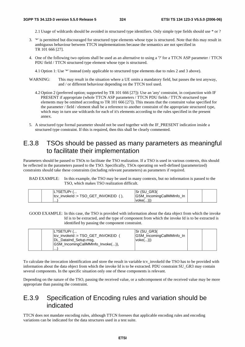
ETSI
ETSI TS 134 123-3 V5.5.0 (2006-06) 3243GPP TS 34.123-3 version 5.5.0 Release 5
2.1 Usage of wildcards should be avoided in structured type identifiers. Only simple type fields should use * or ?
3. '*' is permitted but discouraged for structured type elements whose type is structured. Note that this may result in ambiguous behaviour between TTCN implementations because the semantics are not specified in TR 101 666 [27].
4. One of the following two options shall be used as an alternative to using a '?' for a TTCN ASP parameter / TTCN PDU field / TTCN structured type element whose type is structured.
4.1 Option 1: Use '*' instead (only applicable to structured type elements due to rules 2 and 3 above).
WARNING: This may result in the situation where a UE omits a mandatory field, but passes the test anyway, and / or different behaviour depending on the TTCN tool used.
4.2 Option 2 (preferred option; supported by TR 101 666 [27]): Use an 'any' constraint, in conjunction with IF PRESENT if appropriate (whole TTCN ASP parameters / TTCN PDU fields / TTCN structured type elements may be omitted according to TR 101 666 [27]). This means that the constraint value specified for the parameter / field / element shall be a reference to another constraint of the appropriate structured type, which may in turn use wildcards for each of it's elements according to the rules specified in the present annex.
5. A structured type formal parameter should not be used together with the IF_PRESENT indication inside a structured type constraint. If this is required, then this shall be clearly commented.
E.3.8 TSOs should be passed as many parameters as meaningful to facilitate their implementation
Parameters should be passed to TSOs to facilitate the TSO realization. If a TSO is used in various contexts, this should be reflected in the parameters passed to the TSO. Specifically, TSOs operating on well-defined (parameterized) constraints should take these constraints (including relevant parameters) as parameters if required.
BAD EXAMPLE: In this example, the TSO may be used in many contexts, but no information is passed to the TSO, which makes TSO realization difficult.
L?SETUPr (... tcv_invokeId := TSO_GET_INVOKEID ( ), ...)
Sr (SU_GR3( GSM_IncomingCallMMInfo_Invoke(...)))
GOOD EXAMPLE: In this case, the TSO is provided with information about the data object from which the invoke Id is to be extracted, and the type of component from which the invoke Id is to be extracted is identified by passing the component constraint.
L?SETUPr (... tcv_invokeId := TSO_GET_INVOKEID ( DL_DataInd_Setup.msg, GSM_IncomingCallMMInfo_Invoke(...)), ...)
Sr (SU_GR3( GSM_IncomingCallMMInfo_Invoke(...)))
To calculate the invocation identification and store the result in variable tcv_invokeId the TSO has to be provided with information about the data object from which the invoke Id is to be extracted. PDU constraint SU_GR3 may contain several components. In the specific situation only one of these components is relevant.
Depending on the nature of the TSO, passing the received value, or a subcomponent of the received value may be more appropriate than passing the constraint.
E.3.9 Specification of Encoding rules and variation should be indicated
TTCN does not mandate encoding rules, although TTCN foresees that applicable encoding rules and encoding variations can be indicated for the data structures used in a test suite.

ETSI
ETSI TS 134 123-3 V5.5.0 (2006-06) 3253GPP TS 34.123-3 version 5.5.0 Release 5
There are standards defining encoding rules, e.g. the ITU-T Recommendation X.680 [39] series. However, the type of encoding called "Direct Encoding" - a bit-by-bit-mapping from the data definitions onto the data stream to be transmitted - is not defined anywhere. It therefore needs a "home".
TTCN should therefore define which encoding rules may legally be used by TTCN test suite specifiers. All the encoding rules defined in the ITU-T Recommendation X.680 [39] series should be contained in this repertoire. Additionally an encoding rule called Direct Encoding is needed in particular for tabular TTCN.
ITU-T Recommendation X.680 [39] allows to encode data objects using different length forms (short, long, indefinite). These could be used alternatively as encoding variations. Another encoding variation could be the "minimum encoding", accepting any of the length forms in reception, and using the shortest of the available forms in sending. The variation actually used has to be described somewhere (in the ATS).
E.3.10 Use of global data should be limited The Phase 2 ATS became extremely complex due to the global definition of data. Data should be defined locally where possible if the language allows, alternatively the names of global constraints could be given prefixes to indicate their use.
E.3.11 Limit ATS scope to a single layer / sub-layer Separate ATSs should be produced to test each Layer and perhaps sub Layer. By doing this preambles and common areas particular to one sub Layer can be confined to one test suite and parallel development of test suites can be facilitated.
E.3.12 Place system information in specially designed data structures
System Information data could be stored in specially defined data structures, use of these structures to build PDUs may help to ensure that a consistent set of data is transmitted in all the channels in a cell.
E.3.13 Place channel configuration in specially designed data structures
Likewise the configuration of a 'channel' could be stored in similar structures. This data can then be used to configure the test system and to build Assignment messages to the UE under test. This may help avoid the situation where the TTCN creates one channel and unintentionally commands the mobile to a different, non-existent, channel.
E.3.14 PICS / PIXIT parameters It is desirable to limit the scope of PICS / PIXIT parameters.
A default value shall be provided in the PIXIT document for all PIXIT parameters.
PICS / PIXIT parameters shall not include structured types. If a structured parameter is required, several parameters shall be used, one for each simple element within the type, and a constraint shall be created to combine the simple parameters into a structured type.
For example, to use the following structured type as a parameter.
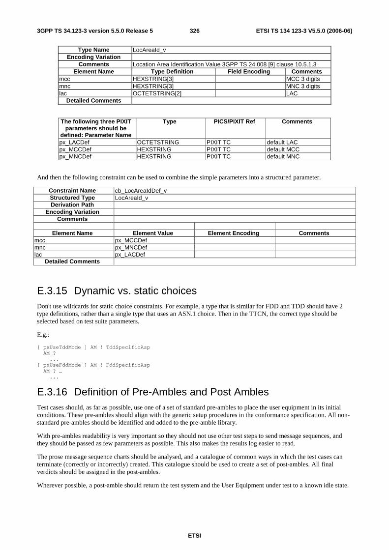
ETSI
ETSI TS 134 123-3 V5.5.0 (2006-06) 3263GPP TS 34.123-3 version 5.5.0 Release 5
Type Name LocAreaId_v Encoding Variation
Comments Location Area Identification Value 3GPP TS 24.008 [9] clause 10.5.1.3 Element Name Type Definition Field Encoding Comments
mcc HEXSTRING[3] MCC 3 digits mnc HEXSTRING[3] MNC 3 digits lac OCTETSTRING[2] LAC
Detailed Comments
The following three PIXIT parameters should be
defined: Parameter Name
Type PICS/PIXIT Ref Comments
px_LACDef OCTETSTRING PIXIT TC default LAC px_MCCDef HEXSTRING PIXIT TC default MCC px_MNCDef HEXSTRING PIXIT TC default MNC
And then the following constraint can be used to combine the simple parameters into a structured parameter.
Constraint Name cb_LocAreaIdDef_v Structured Type LocAreaId_v Derivation Path
Encoding Variation Comments
Element Name Element Value Element Encoding Comments
mcc px_MCCDef mnc px_MNCDef lac px_LACDef
Detailed Comments
E.3.15 Dynamic vs. static choices Don't use wildcards for static choice constraints. For example, a type that is similar for FDD and TDD should have 2 type definitions, rather than a single type that uses an ASN.1 choice. Then in the TTCN, the correct type should be selected based on test suite parameters.
E.g.:
[ pxUseTddMode ] AM ! TddSpecificAsp AM ? ... [ pxUseFddMode ] AM ! FddSpecificAsp AM ? … ...
E.3.16 Definition of Pre-Ambles and Post Ambles Test cases should, as far as possible, use one of a set of standard pre-ambles to place the user equipment in its initial conditions. These pre-ambles should align with the generic setup procedures in the conformance specification. All non-standard pre-ambles should be identified and added to the pre-amble library.
With pre-ambles readability is very important so they should not use other test steps to send message sequences, and they should be passed as few parameters as possible. This also makes the results log easier to read.
The prose message sequence charts should be analysed, and a catalogue of common ways in which the test cases can terminate (correctly or incorrectly) created. This catalogue should be used to create a set of post-ambles. All final verdicts should be assigned in the post-ambles.
Wherever possible, a post-amble should return the test system and the User Equipment under test to a known idle state.

ETSI
ETSI TS 134 123-3 V5.5.0 (2006-06) 3273GPP TS 34.123-3 version 5.5.0 Release 5
E.3.17 Use test steps to encapsulate AT and MMI commands When the same AT or MMI command is to be used more than once within a test suite, the command should be placed within a test step, to ensure that the same information is provided consistently. The main intention of this guideline is to ensure that MMI commands provided to the user are consistent, and can be changed easily if required.
For example, a test step similar to the one illustrated in table E.7 should be created and attached so that the same information is provided to the user each time the test step is used, and the string to be sent only exists in one place within the test suite.
Table E.7: Example test step to encapsulate AT / MMI commandsDefault behaviour
Test Step Name ts_AT_MMI_Example Group Objective Send an MMI command instructing the user to insert the USIM card into the UE. Default
Comments Encapsulate an AT / MMI command within a test step to ensure that the same information is used consistently, and the information only exists in one place within the test suite.
Description Nr Label Behaviour Description Constraints Ref Verdict Comments 1 Ut ! MMI_CmdReq ca_MMICmdReq ( " Please insert the USIM card into
the UE ")
2 Ut ? MMI_CmdCnf ca_MMICmdCnf
Defaults are test steps that are executed when ever a receive event occurs that is not expected. Not expected means that it does not match any of the defined ASP constraints at that point in the test case. The default behaviour used in test case is defined in the test case declaration. They can be defined to stop the test case by calling a standard post-amble or receive the event as OTHERWISE and RETURN back to step where the unexpected event occurred.
A strategy for dealing with unexpected behaviour involving consistent use of defaults should be developed, and applied to test cases wherever possible.
If during a test case or test step it is necessary to change the default behaviour, the ACTIVATE statement may be used.
E.3.18 Use system failure guard timers A timer should be set at the beginning of each test case to guard against system failure. Behaviour on expiry of this timer should be consistent for all test cases.
E.3.19 Mapping between prose specification and individual test cases
The ATS should map one-to-one between test cases and tests as described in 3GPP TS 34.123-1 [1]. A method for ensuring that the two specifications track each other needs to be defined.
E.3.20 Verdict assignment
E.3.20.1 General
Final verdicts shall only be used to indicate test case errors, or when unexpected UE behaviour occurs such that it not sensible to continue the test. When a test case reaches a leaf node, the test case ends, and the current preliminary verdict is assigned. At least one preliminary verdict shall be assigned for every test case. If a test case terminates and no final or preliminary verdicts have been assigned, the current value of the predefined variable R will be 'none', and a test case error is recorded instead of a final verdict.
ETSI
ETSI TS 134 123-3 V5.5.0 (2006-06) 3283GPP TS 34.123-3 version 5.5.0 Release 5
Labels shall be used for every line in which a verdict is posted to improve the traceability of the conformance log produced when the test case is executed. These labels should be kept short, since they appear in the dynamic behaviour tables.
All test suites shall make use of a global boolean variable, defined in the common module, called tcv_TestBody. tcv_TestBody is updated within each test case to indicate if the test body is currently being executed. tcv_TestBody is referenced in defaults and test steps to assign a preliminary inconclusive verdict when unexpected events occur outside of the test body, or a preliminary failure verdict when unexpected events occur within the test body.
The initial value in the declaration of the test case variable tcv_TestBody shall be FALSE. The variable will be bound to this value when the ATS is initialized, and will be re-bound to this value after termination of each test case, ready for execution of the next test case.
E.3.20.2 Test cases
A line similar to line 3 in table E.8 shall be used in all test cases to set tcv_TestBody to TRUE. This line shall have the label TBS to indicate the Test Body Start point.
A line similar to line 6 in table E.8 shall be used in all test cases to set tcv_TestBody to FALSE. This line shall have the label TBE[N] to indicate the Test Body End point. A number N (with one or more digits) may optionally be appended to the label to distinguish between multiple test body end points. If the number of possible test sequences makes management of the tcv_TestBody variable too difficult, the variable can be set to TRUE at the beginning of the test. In this case, a comment shall be added to the test case noting that tcv_TestBody is not updated, so verdicts assigned within preambles and postambles will be treated as if they are part of the test body.
Within the test body, preliminary verdicts shall be used to indicate the result of the test purpose. Each behaviour line within the test body containing a preliminary verdict shall have a label of the form TBXN, where X is one of P, F, I for pass, fail, and inconclusive respectively, and N is a number (with one or more digits) used to distinguish multiple TBPs, TBFs, or TBIs in the same test case.
If an unexpected event occurs corresponding to a test case error, a final inconclusive verdict shall be assigned, and the behaviour line shall have a label ERRN, where N is a number used to distinguish multiple ERRs, and ERR indicates that a test case error has occurred. An example of this is provided in the test step clause.
Table E.8 contains an example test case illustrating these concepts.
In case of a failure event of a time consumed test case (longer than 30 minutes), the test case can be stopped by using a final verdict after the execution of the postamble.

ETSI
ETSI TS 134 123-3 V5.5.0 (2006-06) 3293GPP TS 34.123-3 version 5.5.0 Release 5
Table E.8: Example test case illustrating use of verdicts, labels and tcv_TestBody test case variable
Nr Label Behaviour Description Constraints Ref Verdict Comments 1 +ts_Preambles 2 TBS ( tcv_TestBody := TRUE ) 1 3 L ! Stimulus cs_Stimulus1 4 +lt_Response 5 TBE (tcv_TestBody := FALSE ) (P) 2 6 +ts_Postambles lt_Response 7 TBP1 L ? Response cr_ValidResponse1 (P) 3 8 TBP2 L ? Response cr_ValidResponse2 (P) 3 9 TBF1 L ? Response cr_InvalidResponse (F) 4 10 TBI1 L ? Response cr_OtherResponse (I) 5 Detailed comments 1. The behaviour line setting tcv_TestBody to TRUE shall have the label TBS.
2. The behaviour line setting tcv_TestBody to FALSE shall have the label TBE, and can optionally be used to assign a verdict indicating that the test purpose has passed or failed (i.e. if the final behaviour statement in the test body is a tree attachment).
3. The label TBPN is used to indicate that the test purpose has been achieved via the Nth possible valid UE behaviour.
4. The label TBFN is used to indicate that the test purpose has not been achieved, due to the Nth possible failure cause.
5. The label TBIN is used to indicate that the test result is inconclusive for the Nth possible unexpected / unknown event.
E.3.20.3 Test steps
To promote re-use, test steps shall only assign preliminary verdicts (I) and (F). (P) verdicts shall be managed at the test case level in general, but may be used sparingly within test steps. ETR 141 [37] clause 12.4 recommends that a preliminary pass verdict should be assigned at the leaf of each passing event sequence of the test step. If a test step includes an alternative for unexpected / invalid behaviour, then either a preliminary inconclusive verdict shall be assigned if tcv_TestBody is FALSE, or a preliminary failure verdict shall be assigned if tcv_TestBody is TRUE.
Each behaviour line within the test step containing a preliminary verdict shall have a label of the form TSXN, where X is one of P, F or I for pass, fail, and inconclusive respectively, and N is a number (with one or more digits) used to distinguish multiple TSPs, TSFs, or TSIs in the same test step.
If an unexpected event occurs corresponding to a test case error, a final inconclusive verdict shall be assigned, and the behaviour line shall have a label ERRN, where N is a number used to distinguish multiple ERRs, and ERR indicates that a test case error has occurred.
Table E.9 contains an example test step illustrating these concepts.
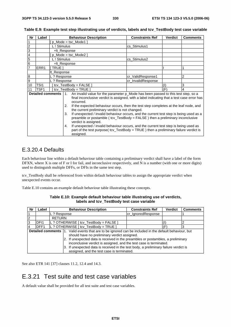
ETSI
ETSI TS 134 123-3 V5.5.0 (2006-06) 3303GPP TS 34.123-3 version 5.5.0 Release 5
Table E.9: Example test step illustrating use of verdicts, labels and tcv_TestBody test case variable
Nr Label Behaviour Description Constraints Ref Verdict Comments 1 [ p_Mode = tsc_Mode1 ] 2 L ! Stimulus cs_Stimulus1 3 +lt_Response 4 [ p_Mode = tsc_Mode2 ] 5 L ! Stimulus cs_Stimulus2 6 +lt_Response 7 ERR1 [ TRUE ] I 1 lt_Response 8 L ? Response cr_ValidResponse1 2 9 L ? Response cr_InvalidResponse 10 TSI1 [ tcv_TestBody = FALSE ] (I) 3 11 TSF1 [ tcv_TestBody = TRUE ] (F) 4 Detailed comments 1. An invalid value for the parameter p_Mode has been passed to this test step, so a
final inconclusive verdict is assigned, with a label indicating that a test case error has occurred.
2. If the expected behaviour occurs, then the test step completes at the leaf node, and the current preliminary verdict is not changed.
3. If unexpected / invalid behaviour occurs, and the current test step is being used as a preamble or postamble ( tcv_TestBody = FALSE ) then a preliminary inconclusive verdict is assigned.
4. If unexpected / invalid behaviour occurs, and the current test step is being used as part of the test purpose( tcv_TestBody = TRUE ) then a preliminary failure verdict is assigned.
E.3.20.4 Defaults
Each behaviour line within a default behaviour table containing a preliminary verdict shall have a label of the form DFXN, where X is one of F or I for fail, and inconclusive respectively, and N is a number (with one or more digits) used to distinguish multiple DFFs, or DFIs in the same test step.
tcv_TestBody shall be referenced from within default behaviour tables to assign the appropriate verdict when unexpected events occur.
Table E.10 contains an example default behaviour table illustrating these concepts.
Table E.10: Example default behaviour table illustrating use of verdicts, labels and tcv_TestBody test case variable
Nr Label Behaviour Description Constraints Ref Verdict Comments 1 L ? Response cr_IgnoredResponse 1 2 RETURN 3 DFI1 L ? OTHERWISE [ tcv_TestBody = FALSE ] (I) 2 4 DFF1 L ? OTHERWISE [ tcv_TestBody = TRUE ] (F) 3 Detailed comments 1. Valid events that are to be ignored can be included in the default behaviour, but
should have no preliminary verdict assigned. 2. If unexpected data is received in the preambles or postambles, a preliminary
inconclusive verdict is assigned, and the test case is terminated. 3. If unexpected data is received in the test body, a preliminary failure verdict is
assigned, and the test case is terminated.
See also ETR 141 [37] clauses 11.2, 12.4 and 14.3.
E.3.21 Test suite and test case variables A default value shall be provided for all test suite and test case variables.

ETSI
ETSI TS 134 123-3 V5.5.0 (2006-06) 3313GPP TS 34.123-3 version 5.5.0 Release 5
E.3.22 Use of macros is forbidden The use of macros is forbidden, to support migration to TTCN3.
E.3.23 Support for future Radio Access Technologies To allow existing test cases to be updated in future to support other radio access technologies, test suites shall make use of a PIXIT parameter px_RAT of type RatType as shown in the following example.
Test Case Name tc_RAT_Example1 Nr Label Behaviour Description Constraints Ref Verdict Comments
1 START t_Guard( 300 ) 2 [ px_RAT = fdd ] 3 PCO ! FDD_PDU c_FDD_PDU1 FDD specific behaviour 4 TBP1 PCO ? COMMON_PDU c_COMMON_PDU1 (P) 5 [ px_RAT = tdd ] 6 PCO ! TDD_PDU c_TDD_PDU1 TDD specific behaviour 7 TBP2 PCO ? COMMON_PDU c_COMMON_PDU1 (P) 8 [ px_RAT = other_rat ] I Tests for this RAT not implemented yet
9 TCE1 [ TRUE ] I Unexpected px_RAT value Detailed Comments
In general, alternatives should be used to separate behaviour specific for each RAT, and common behaviour should be re-used as much as possible. A final inconclusive verdict shall be used for any alternatives that have not been implemented yet.
Local trees may be used as shown in the following example to improve re-use of common behaviour.
Test Case Name tc_RAT_Example2
Nr Label Behaviour Description Constraints Ref Verdict Comments 1 START t_Guard( 300 ) 2 +lt_RAT_SpecificPart 3 TBP1 PCO ? COMMON_PDU c_COMMON_PDU1 (P) Common behaviour lt_RAT_SpecificPart 4 [ px_RAT = fdd ] 5 PCO ! FDD_PDU c_FDD_PDU1 FDD specific behaviour 6 [ px_RAT = tdd ] 7 PCO ! TDD_PDU c_TDD_PDU1 TDD specific behaviour 8 TCE1 [ TRUE ] (I) Unexpected px_RAT value Detailed Comments
E.3.24 Managing multiple representations of the same information When the same information is represented using multiple types within the same test suite, it is necessary to manage conversions between the types, and ensure that the information remains consistent across all of the representations.
For example, IMSI is represented as 'SEQUENCE (SIZE (6..15)) OF Digit' in the RRC ASN.1 definitions, as a HEXSTRING for input as a PIXIT parameter, and as an information element defined in TTCN tabular format for MM.
E.3.24.1 Predefined types
Conversion operations are not required to convert the following TTCN predefined types to their counterparts in ASN.1.
a) INTEGER predefined type.
b) BOOLEAN predefined type.

ETSI
ETSI TS 134 123-3 V5.5.0 (2006-06) 3323GPP TS 34.123-3 version 5.5.0 Release 5
c) BITSTRING predefined type.
d) HEXSTRING predefined type.
e) OCTETSTRING predefined type.
f) OBJECTIDENTIFIER predefined type.
g) R_TYPE predefined type.
h) CharacterString predefined types.
Therefore it is valid to pass a value of type BIT STRING (ASN.1) as a formal parameter of type BITSTRING (TTCN predefined).
E.3.24.2 Simple types
TR 101 666 [27] clause 11.2.1 states:
- "TTCN is a weakly typed language, in that values of any two types which have the same base type are considered to be type compatible (e.g. for the purposes of performing assignments or parameter passing)".
When simple types have restrictions, it is the TTCN author's responsibility to ensure that the restrictions are compatible. The TTCN compiler provides some assistance with this, but the extent of the checking is compiler specific.
E.3.24.3 Structured types
For conversion between more complex representations, test suite operations will generally be required. If the mapping is simple enough, it may be possible to perform the conversion using a test step, which takes the common representation as a parameter, and stores the required representation in a test case variable. This may avoid the need for an extra test suite operation.
E.3.24.4 Conversion responsibility
Two design approaches are possible for deciding where the responsibility of conversion lies: Calling party conversion and called party conversion.
The appropriate option should be selected on a case-by-case basis with the following restrictions:
- If one representation of the information is a PIXIT parameter, and this information must be passed to a test step, the called party conversion option shall be used, and the formal parameter to the test step shall always have the same type as the PIXIT parameter.
- If a test step provides multiple alternatives for different radio access technologies, which require different representations of the same information, the called party conversion convention shall be used. In this case a technology independent representation of the information shall be passed as a parameter, and the test step shall perform the conversion to the appropriate type depending on which RAT is being used.
E.3.24.5 Option 1: Calling party conversions
For this approach, each test step provides an interface based on its internal representation. It is the responsibility of the test case / step attaching the test step to perform the conversion before the attachment.
E.3.24.5.1 Advantages
- The number of calls to conversion operations is minimized.
- The complexity of the attached test steps is reduced because fewer conversions are required than for the called party conversion approach.
ETSI
ETSI TS 134 123-3 V5.5.0 (2006-06) 3333GPP TS 34.123-3 version 5.5.0 Release 5
E.3.24.5.2 Disadvantages
- Different types are used to transfer the same information across the test step interfaces.
- The complexity of the attaching test steps / cases may be increased because conversions are required before attaching a test step.
- The attaching test steps / cases are responsible for ensuring that multiple representations contain consistent information.
E.3.24.6 Option 2: Called party conversions
In this case, the same representation is used wherever the information must be used as a formal parameter value to a test step, and it is the responsibility of the test step to perform any conversions required.
E.3.24.6.1 Advantages
- The complexity in the attaching test case / step is reduced, which will often improve readability.
- The test step interfaces are cleaner, because the same representation is always passed as a formal parameter.
- Internal representations may be hidden within test steps so that calling parties do not need to have any knowledge of them.
E.3.24.6.2 Disadvantages
- Conversion operations may be called more times than necessary, for example if the same test step is attached twice within one test case.
E.3.25 Assignment using constraint According to TR 101 666 [27], the Right Hand Side (RHS) of an assignment shall not contain any unbound variables. The matching symbols, AnyValue or AnyOrOmit, in both tabular and ASN.1 constraints shall not be assigned to a test case variable, independent of the type of the test case variable.
E.3.26 Guidelines for use of timers when tolerances are applicable Timed events within the test suite should implement the timer tolerances specified in 3GPP TS 34.108 [3], clause 4.2.3. It is the TTCN author's responsibility to ensure that appropriate tolerance checks and tolerance values are being used.
NOTE: Tolerances are not applicable to guard timers as described in clause E.3.18 of the present document.
E.3.26.1 Specific situations
The present clause provides recommendations for how to implement timers with tolerances for the following situations:
a) The timed event must occur before a given time.
b) The timed event must occur after a given time.
c) The timed event must occur between two given times.
NOTE: A specific case of this situation is when the desired event occurs at a specific time, plus or minus a tolerance.
E.3.26.2 Example situations
The examples below assume:
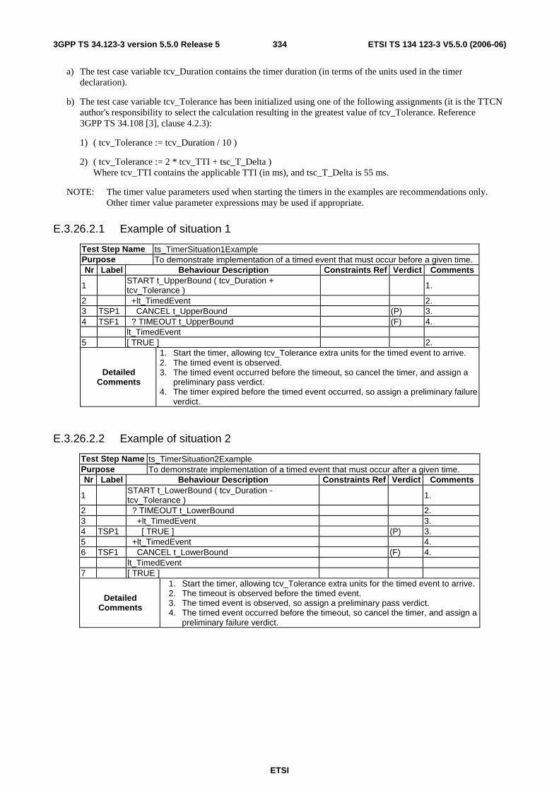
ETSI
ETSI TS 134 123-3 V5.5.0 (2006-06) 3343GPP TS 34.123-3 version 5.5.0 Release 5
a) The test case variable tcv_Duration contains the timer duration (in terms of the units used in the timer declaration).
b) The test case variable tcv_Tolerance has been initialized using one of the following assignments (it is the TTCN author's responsibility to select the calculation resulting in the greatest value of tcv_Tolerance. Reference 3GPP TS 34.108 [3], clause 4.2.3):
1) ( tcv_Tolerance := tcv_Duration / 10 )
2) ( tcv_Tolerance := 2 * tcv_TTI + tsc_T_Delta ) Where tcv_TTI contains the applicable TTI (in ms), and tsc_T_Delta is 55 ms.
NOTE: The timer value parameters used when starting the timers in the examples are recommendations only. Other timer value parameter expressions may be used if appropriate.
E.3.26.2.1 Example of situation 1
Test Step Name ts_TimerSituation1Example Purpose To demonstrate implementation of a timed event that must occur before a given time. Nr Label Behaviour Description Constraints Ref Verdict Comments
1 START t_UpperBound ( tcv_Duration + tcv_Tolerance ) 1.
2 +lt_TimedEvent 2. 3 TSP1 CANCEL t_UpperBound (P) 3. 4 TSF1 ? TIMEOUT t_UpperBound (F) 4. lt_TimedEvent 5 [ TRUE ] 2.
Detailed Comments
1. Start the timer, allowing tcv_Tolerance extra units for the timed event to arrive. 2. The timed event is observed. 3. The timed event occurred before the timeout, so cancel the timer, and assign a
preliminary pass verdict. 4. The timer expired before the timed event occurred, so assign a preliminary failure
verdict.
E.3.26.2.2 Example of situation 2
Test Step Name ts_TimerSituation2Example Purpose To demonstrate implementation of a timed event that must occur after a given time. Nr Label Behaviour Description Constraints Ref Verdict Comments
1 START t_LowerBound ( tcv_Duration - tcv_Tolerance ) 1.
2 ? TIMEOUT t_LowerBound 2. 3 +lt_TimedEvent 3. 4 TSP1 [ TRUE ] (P) 3. 5 +lt_TimedEvent 4. 6 TSF1 CANCEL t_LowerBound (F) 4. lt_TimedEvent 7 [ TRUE ]
Detailed Comments
1. Start the timer, allowing tcv_Tolerance extra units for the timed event to arrive. 2. The timeout is observed before the timed event. 3. The timed event is observed, so assign a preliminary pass verdict. 4. The timed event occurred before the timeout, so cancel the timer, and assign a
preliminary failure verdict.

ETSI
ETSI TS 134 123-3 V5.5.0 (2006-06) 3353GPP TS 34.123-3 version 5.5.0 Release 5
E.3.26.2.3 Example of situation 3
Test Step Name ts_TimerSituation3Example
Purpose To demonstrate implementation of a timed event that must occur between two given times.
Nr Label Behaviour Description Constraints Ref
Verdict Comments
1
START t_UpperBound ( tcv_Duration + tcv_Tolerance ), START t_LowerBound ( tcv_Duration - tcv_Tolerance )
1.
2 ? TIMEOUT t_LowerBound 2. 3 +lt_TimedEvent 3 4 TSP1 CANCEL t_UpperBound (P) 3. 5 TSF1 ? TIMEOUT t_UpperBound (F) 4. 6 +lt_TimedEvent 5.
7 TSF2 CANCEL t_LowerBound , CANCEL t_UpperBound (F)
lt_TimedEvent 8 [ TRUE ]
Detailed Comments
1. Start the upper and lower bound timers, allowing tcv_Tolerance extra units each side of the expected time for the timed event to arrive.
2. The lower bound timeout is observed before the timed event. 3. The timed event is observed, so cancel the upper bound timer, and a
preliminary pass verdict is assigned. 4. The upper bound timer expired before the timed event occurred, so a
preliminary failure verdict is assigned. 5. The timed event occurred before the lower bound timer expired, so a
preliminary failure verdict is assigned.

ETSI
ETSI TS 134 123-3 V5.5.0 (2006-06) 3363GPP TS 34.123-3 version 5.5.0 Release 5
Annex F (void): Void Void.
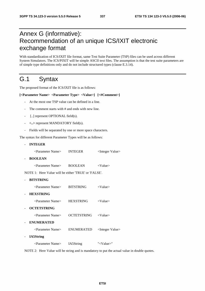
ETSI
ETSI TS 134 123-3 V5.5.0 (2006-06) 3373GPP TS 34.123-3 version 5.5.0 Release 5
Annex G (informative): Recommendation of an unique ICS/IXIT electronic exchange format With standardization of ICS/IXIT file format, same Test Suite Parameter (TSP) files can be used across different System Simulators. The ICS/PIXIT will be simple ASCII text files. The assumption is that the test suite parameters are of simple type definitions only and do not include structured types (clause E.3.14).
G.1 Syntax The proposed format of the ICS/IXIT file is as follows:
[<Parameter Name> <Parameter Type> <Value>] [<#Comment>]
- At the most one TSP value can be defined in a line.
- The comment starts with # and ends with new line.
- [..] represent OPTIONAL field(s).
- <..> represent MANDATORY field(s).
- Fields will be separated by one or more space characters.
The syntax for different Parameter Types will be as follows:
- INTEGER
<Parameter Name> INTEGER <Integer Value>
- BOOLEAN
<Parameter Name> BOOLEAN <Value>
NOTE 1: Here Value will be either 'TRUE' or 'FALSE'.
- BITSTRING
<Parameter Name> BITSTRING <Value>
- HEXSTRING
<Parameter Name> HEXSTRING <Value>
- OCTETSTRING
<Parameter Name> OCTETSTRING <Value>
- ENUMERATED
<Parameter Name> ENUMERATED <Integer Value>
- IA5String
<Parameter Name> IA5String "<Value>"
NOTE 2: Here Value will be string and is mandatory to put the actual value in double quotes.

ETSI
ETSI TS 134 123-3 V5.5.0 (2006-06) 3383GPP TS 34.123-3 version 5.5.0 Release 5
G.2 Examples This clause gives an example of ICS/IXIT file format.
# TSP file version 1.0.0
px_CS BOOLEAN TRUE # TRUE if Circuit Switched is applicable
px_PTMSI_Def OCTETSTRING 12345678 #Default PTMSI
px_RAT ENUMERATED 0 #px_RAT is of Type RatType and is of Type of ENUMERATED {fdd(0), tdd(1)}.
px_Region IA5String "Europe" #px_Region is of Type Region and is of Type IA5String ("Europe", Japan").
px_PriScrmCodeA INTEGER 100 #px_PriScrmCodeA is of Type PrimaryScramblingCode and is of Type INTEGER (0..511).
px_SRNC_Id BITSTRING 000000000001 #px_SRNC_Id is of Type SRNC_Identity and is of Type BIT STRING (SIZE(12)).
px_IMSI_Def HEXSTRING 001010123456063 #Default IMSI
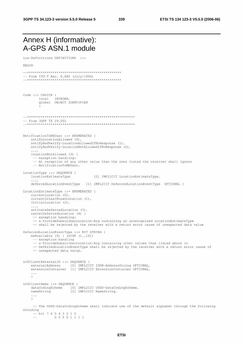
ETSI
ETSI TS 134 123-3 V5.5.0 (2006-06) 3393GPP TS 34.123-3 version 5.5.0 Release 5
Annex H (informative): A-GPS ASN.1 module Lcs-Definitions DEFINITIONS ::= BEGIN --************************************************ -- From ITU-T Rec. X.880 (July/1994) --************************************************ Code ::= CHOICE { local INTEGER, global OBJECT IDENTIFIER } --******************************************************* -- From 3GPP TS 29.002 --******************************************************* NotificationToMSUser ::= ENUMERATED { notifyLocationAllowed (0), notifyAndVerify-LocationAllowedIfNoResponse (1), notifyAndVerify-LocationNotAllowedIfNoResponse (2), ..., locationNotAllowed (3) } -- exception handling: -- At reception of any other value than the ones listed the receiver shall ignore -- NotificationToMSUser. LocationType ::= SEQUENCE { locationEstimateType [0] IMPLICIT LocationEstimateType, ..., deferredLocationEventType [1] IMPLICIT DeferredLocationEventType OPTIONAL } LocationEstimateType ::= ENUMERATED { currentLocation (0), currentOrLastKnownLocation (1), initialLocation (2), ..., activateDeferredLocation (3), cancelDeferredLocation (4) } -- exception handling: -- a ProvideSubscriberLocation-Arg containing an unrecognized LocationEstimateType -- shall be rejected by the receiver with a return error cause of unexpected data value DeferredLocationEventType ::= BIT STRING { msAvailable (0) } (SIZE (1..16)) -- exception handling -- a ProvideSubscriberLocation-Arg containing other values than listed above in -- DeferredLocationEventType shall be rejected by the receiver with a return error cause of -- unexpected data value. LCSClientExternalID ::= SEQUENCE { externalAddress [0] IMPLICIT ISDN-AddressString OPTIONAL, extensionContainer [1] IMPLICIT ExtensionContainer OPTIONAL, ... } LCSClientName ::= SEQUENCE { dataCodingScheme [0] IMPLICIT USSD-DataCodingScheme, nameString [2] IMPLICIT NameString, ... } -- The USSD-DataCodingScheme shall indicate use of the default alphabet through the following encoding -- bit 7 6 5 4 3 2 1 0 -- 0 0 0 0 1 1 1 1
ETSI
ETSI TS 134 123-3 V5.5.0 (2006-06) 3403GPP TS 34.123-3 version 5.5.0 Release 5
NameString ::= USSD-String (SIZE (1..maxNameStringLength)) maxNameStringLength INTEGER ::= 63 USSD-DataCodingScheme ::= OCTET STRING (SIZE (1)) -- The structure of the USSD-DataCodingScheme is defined by the Cell -- Broadcast Data Coding Scheme as described in TS 3GPP TS 23.038 [54] LCSRequestorID ::= SEQUENCE { dataCodingScheme [0] IMPLICIT USSD-DataCodingScheme, requestorIDString [1] IMPLICIT RequestorIDString, ... } RequestorIDString ::= USSD-String (SIZE (1..maxRequestorIDStringLength)) maxRequestorIDStringLength INTEGER ::= 63 LCSCodeword ::= SEQUENCE { dataCodingScheme [0] IMPLICIT USSD-DataCodingScheme, lcsCodewordString [1] IMPLICIT LCSCodewordString, ... } LCSCodewordString ::= USSD-String (SIZE (1..maxLCSCodewordStringLength)) maxLCSCodewordStringLength INTEGER ::= 20 LCSServiceTypeID ::= INTEGER (0..127) -- the integer values 0-63 are reserved for Standard LCS service types -- the integer values 64-127 are reserved for Non Standard LCS service types USSD-String ::= OCTET STRING (SIZE (1..maxUSSD-StringLength)) -- The structure of the contents of the USSD-String is dependent -- on the USSD-DataCodingScheme as described in TS 3GPP TS 23.038 [25]. maxUSSD-StringLength INTEGER ::= 160 ISDN-AddressString ::= AddressString (SIZE (1..maxISDN-AddressLength)) -- This type is used to represent ISDN numbers. maxISDN-AddressLength INTEGER ::= 9 AddressString ::= OCTET STRING (SIZE (1..maxAddressLength)) -- This type is used to represent a number for addressing purposes. It is -- composed of -- a) one octet for nature of address, and numbering plan indicator. -- b) digits of an address encoded as TBCD-String. -- a) The first octet includes a one bit extension indicator, a -- 3 bits nature of address indicator and a 4 bits numbering -- plan indicator, encoded as follows: -- bit 8: 1 (no extension) -- bits 765: nature of address indicator -- 000 unknown -- 001 international number -- 010 national significant number -- 011 network specific number -- 100 subscriber number -- 101 reserved -- 110 abbreviated number -- 111 reserved for extension -- bits 4321: numbering plan indicator -- 0000 unknown -- 0001 ISDN/Telephony Numbering Plan (Rec ITU-T E.164) -- 0010 spare -- 0011 data numbering plan (ITU-T Rec X.121) -- 0100 telex numbering plan (ITU-T Rec F.69) -- 0101 spare
ETSI
ETSI TS 134 123-3 V5.5.0 (2006-06) 3413GPP TS 34.123-3 version 5.5.0 Release 5
-- 0110 land mobile numbering plan (ITU-T Rec E.212) -- 0111 spare -- 1000 national numbering plan -- 1001 private numbering plan -- 1111 reserved for extension -- all other values are reserved. -- b) The following octets representing digits of an address -- encoded as a TBCD-STRING. maxAddressLength INTEGER ::= 20 LCS-QoS ::= SEQUENCE { horizontal-accuracy [0] IMPLICIT Horizontal-Accuracy OPTIONAL, verticalCoordinateRequest [1] IMPLICIT NULL OPTIONAL, vertical-accuracy [2] IMPLICIT Vertical-Accuracy OPTIONAL, responseTime [3] IMPLICIT ResponseTime OPTIONAL, extensionContainer [4] IMPLICIT ExtensionContainer OPTIONAL, ... } Horizontal-Accuracy ::= OCTET STRING (SIZE (1)) -- bit 8 = 0 -- bits 7-1 = 7 bit Uncertainty Code defined in 3GPP TS 23.032. The horizontal location -- error should be less than the error indicated by the uncertainty code with 67% -- confidence. Vertical-Accuracy ::= OCTET STRING (SIZE (1)) -- bit 8 = 0 -- bits 7-1 = 7 bit Vertical Uncertainty Code defined in 3GPP TS 23.032. -- The vertical location error should be less than the error indicated -- by the uncertainty code with 67% confidence. ResponseTime ::= SEQUENCE { responseTimeCategory ResponseTimeCategory, ... } -- note: an expandable SEQUENCE simplifies later addition of a numeric response time. ResponseTimeCategory ::= ENUMERATED { lowdelay (0), delaytolerant (1), ... } -- exception handling: -- an unrecognized value shall be treated the same as value 1 (delaytolerant) SupportedGADShapes ::= BIT STRING { ellipsoidPoint (0), ellipsoidPointWithUncertaintyCircle (1), ellipsoidPointWithUncertaintyEllipse (2), polygon (3), ellipsoidPointWithAltitude (4), ellipsoidPointWithAltitudeAndUncertaintyElipsoid (5), ellipsoidArc (6) } (SIZE (7..16)) -- A node shall mark in the BIT STRING all Shapes defined in 3GPP TS 23.032 it supports. -- exception handling: bits 7 to 15 shall be ignored if received. Ext-GeographicalInformation ::= OCTET STRING (SIZE (1..maxExt-GeographicalInformation)) -- Refers to geographical Information defined in 3GPP TS 23.032. -- This is composed of 1 or more octets with an internal structure according to -- 3GPP TS 23.032 -- Octet 1: Type of shape, only the following shapes in 3GPP TS 23.032 are allowed: -- (a) Ellipsoid point with uncertainty circle -- (b) Ellipsoid point with uncertainty ellipse -- (c) Ellipsoid point with altitude and uncertainty ellipsoid -- (d) Ellipsoid Arc -- (e) Ellipsoid Point -- Any other value in octet 1 shall be treated as invalid -- Octets 2 to 8 for case (a) Ellipsoid point with uncertainty circle -- Degrees of Latitude 3 octets -- Degrees of Longitude 3 octets -- Uncertainty code 1 octet -- Octets 2 to 11 for case (b) Ellipsoid point with uncertainty ellipse:

ETSI
ETSI TS 134 123-3 V5.5.0 (2006-06) 3423GPP TS 34.123-3 version 5.5.0 Release 5
-- Degrees of Latitude 3 octets -- Degrees of Longitude 3 octets -- Uncertainty semi-major axis 1 octet -- Uncertainty semi-minor axis 1 octet -- Angle of major axis 1 octet -- Confidence 1 octet -- Octets 2 to 14 for case (c) Ellipsoid point with altitude and uncertainty ellipsoid -- Degrees of Latitude 3 octets -- Degrees of Longitude 3 octets -- Altitude 2 octets -- Uncertainty semi-major axis 1 octet -- Uncertainty semi-minor axis 1 octet -- Angle of major axis 1 octet -- Uncertainty altitude 1 octet -- Confidence 1 octet -- Octets 2 to 13 for case (d) Ellipsoid Arc -- Degrees of Latitude 3 octets -- Degrees of Longitude 3 octets -- Inner radius 2 octets -- Uncertainty radius 1 octet -- Offset angle 1 octet -- Included angle 1 octet -- Confidence 1 octet -- Octets 2 to 7 for case (e) Ellipsoid Point -- Degrees of Latitude 3 octets -- Degrees of Longitude 3 octets -- -- An Ext-GeographicalInformation parameter comprising more than one octet and -- containing any other shape or an incorrect number of octets or coding according -- to 3GPP TS 23.032 shall be treated as invalid data by a receiver. -- -- An Ext-GeographicalInformation parameter comprising one octet shall be discarded -- by the receiver if an Add-GeographicalInformation parameter is received -- in the same message. -- -- An Ext-GeographicalInformation parameter comprising one octet shall be treated as -- invalid data by the receiver if an Add-GeographicalInformation parameter is not -- received in the same message. maxExt-GeographicalInformation INTEGER ::= 20 -- the maximum length allows for further shapes in 3GPP TS 23.032 to be included in later -- versions of 3GPP TS 29.002 Add-GeographicalInformation ::= OCTET STRING (SIZE (1..maxAdd-GeographicalInformation)) -- Refers to geographical Information defined in 3GPP TS 23.032. -- This is composed of 1 or more octets with an internal structure according to -- 3GPP TS 23.032 -- Octet 1: Type of shape, all the shapes defined in 3GPP TS 23.032 are allowed: -- Octets 2 to n (where n is the total number of octets necessary to encode the shape -- according to 3GPP TS 23.032) are used to encode the shape itself in accordance with the -- encoding defined in 3GPP TS 23.032 -- -- An Add-GeographicalInformation parameter, whether valid or invalid, received -- together with a valid Ext-GeographicalInformation parameter in the same message -- shall be discarded. -- -- An Add-GeographicalInformation parameter containing any shape not defined in -- 3GPP TS 23.032 or an incorrect number of octets or coding according to -- 3GPP TS 23.032 shall be treated as invalid data by a receiver if not received -- together with a valid Ext-GeographicalInformation parameter in the same message. maxAdd-GeographicalInformation INTEGER ::= 91 -- the maximum length allows support for all the shapes currently defined in 3GPP TS 23.032 --******************************************************** -- Derived from ITU-T Rec. Q.773 (June/1997) --******************************************************** Component ::= CHOICE { invoke [1] IMPLICIT Invoke, returnResultLast [2] IMPLICIT ReturnResult, returnError [3] IMPLICIT ReturnError, reject [4] IMPLICIT Reject }

ETSI
ETSI TS 134 123-3 V5.5.0 (2006-06) 3433GPP TS 34.123-3 version 5.5.0 Release 5
-- The used part of Q.773 is almost the same as the component portion of TC messages. The only -- difference is that returnResultNotLast is not used. (see 24.080, clause 3.6.1) Invoke ::= SEQUENCE { invokeID InvokeIdType, linkedID [0] IMPLICIT InvokeIdType OPTIONAL, operationCode Code, -- local:116 for lcsNotification -- local:115 for lcs-MOLR parameter InvokeArgument OPTIONAL } ReturnResult ::= SEQUENCE { invokeID InvokeIdType, result SEQUENCE { operationCode Code, -- local:116 for lcsNotification -- local:115 for lcs-MOLR parameter ReturnRes } OPTIONAL } ReturnError ::= SEQUENCE { invokeID InvokeIdType, errorCode Code, -- local:34 for SystemFailure -- local:36 for UnexpectedDataValue -- local:35 for DataMissing -- local:21 for FacilityNotSupported -- local:19 for SS-SubscriptionViolation -- local:54 for PositionMethodFailure parameter ReturnErrPara OPTIONAL } Reject ::= SEQUENCE { invokeID CHOICE { derivable InvokeIdType, not-derivable NULL }, problem CHOICE { generalProblem [0] IMPLICIT GeneralProblem, invokeProblem [1] IMPLICIT InvokeProblem, returnResultProblem [2] IMPLICIT ReturnResultProblem, returnErrorProblem [3] IMPLICIT ReturnErrorProblem } } InvokeIdType ::= INTEGER (-128..127) GeneralProblem ::= INTEGER { unrecognizedComponent (0), mistypedComponent (1), badlyStructuredComponent (2) } InvokeProblem ::= INTEGER {duplicateInvokeID (0), unrecognizedOperation (1), mistypedParameter (2), resourceLimitation (3), initiatingRelease (4), unrecognizedLinkedID (5), linkedResponseUnexpected (6), unexpectedLinkedOperation (7) } ReturnResultProblem ::= INTEGER {unrecognizedInvokeID (0), returnResultUnexpected (1), mistypedParameter (2) } ReturnErrorProblem ::= INTEGER {unrecognizedInvokeID (0), returnErrorUnexpected (1), unrecognizedError (2), unexpectedError (3), mistypedParameter (4) }
ETSI
ETSI TS 134 123-3 V5.5.0 (2006-06) 3443GPP TS 34.123-3 version 5.5.0 Release 5
--***************************************************** --Derived from SS-DataTypes in 3GPP TS 24.080 ver.540 --***************************************************** Components ::= SET OF Component InvokeArgument ::= CHOICE { lcsNotification LocationNotificationArg, lcs-MOLR LCS-MOLRArg } ReturnRes ::= CHOICE { lcsNotifficationRes LocationNotificationRes, lcsMOLRRes LCS-MOLRRes } ReturnErrPara ::= CHOICE { lcsNotifficationErrPara LcsNotificationErrPara, lcs-MOLR-ResErrPara Lcs-MOLR-ErrPara } LocationNotificationArg ::= SEQUENCE { notificationType [0] IMPLICIT NotificationToMSUser, locationType [1] IMPLICIT LocationType, lcsClientExternalID [2] IMPLICIT LCSClientExternalID OPTIONAL, lcsClientName [3] IMPLICIT LCSClientName OPTIONAL, ..., lcsRequestorID [4] IMPLICIT LCSRequestorID OPTIONAL, lcsCodeword [5] IMPLICIT LCSCodeword OPTIONAL, lcsServiceTypeID [6] IMPLICIT LCSServiceTypeID OPTIONAL } -- exception handling: -- At reception of an unrecognised notificationType value the receiver shall reject the -- operation with a return error cause of unexpected data value. -- At reception of an unrecognised locationType value the receiver shall reject the -- operation with a return error cause of unexpected data value. LocationNotificationRes ::= SEQUENCE { verificationResponse [0] IMPLICIT VerificationResponse OPTIONAL, ... } VerificationResponse::= ENUMERATED { permissionDenied (0), permissionGranted (1), ... } -- exception handling: -- an unrecognized value shall be treated the same as value 0 (permissionDenied) LcsNotificationErrPara ::= CHOICE { systemFailure SystemFailureParam, unexpectedDataValue UnexpectedDataParam } -- This is derived from information object "lcs-LocationNotification" LCS-MOLRArg ::= SEQUENCE { molr-Type [0] IMPLICIT MOLR-Type, locationMethod [1] IMPLICIT LocationMethod OPTIONAL, lcs-QoS [2] IMPLICIT LCS-QoS OPTIONAL, lcsClientExternalID [3] IMPLICIT LCSClientExternalID OPTIONAL, mlc-Number [4] IMPLICIT ISDN-AddressString OPTIONAL, gpsAssistanceData [5] IMPLICIT GPSAssistanceData OPTIONAL, ..., supportedGADShapes [6] IMPLICIT SupportedGADShapes OPTIONAL }

ETSI
ETSI TS 134 123-3 V5.5.0 (2006-06) 3453GPP TS 34.123-3 version 5.5.0 Release 5
-- The parameter locationMethod shall be included if and only if the -- molr-Type is set to value deCipheringKeys or assistanceData. -- The parameter gpsAssistanceData shall be included if and only if the -- molr-Type is set to value assistanceData and -- locationMethod is set to value assistedGPS. MOLR-Type ::= ENUMERATED { locationEstimate (0), assistanceData (1), deCipheringKeys (2), ... } -- exception handling: -- an unrecognized value shall be rejected by the receiver with a return error cause of -- unexpected data value. LocationMethod ::= ENUMERATED { msBasedEOTD (0), msAssistedEOTD (1), assistedGPS (2), ..., msBasedOTDOA (3) } -- exception handling: -- When this parameter is received with value msBasedEOTD or msAssistedEOTD and the MS -- is camped on an UMTS Service Area then the receiver shall reject it -- with a return error cause of unexpected data value. -- When this parameter is received with value msBasedOTDOA and the MS -- is camped on a GSM Cell then the receiver shall reject it with -- a return error cause of unexpected data value. -- an unrecognized value shall be rejected by the receiver with -- a return error cause of unexpected data value. GPSAssistanceData ::= OCTET STRING (SIZE (1..38)) -- Octets 1 to 38 are coded in the same way as the octets 3 to 7+2n -- of Requested GPS Data IE in 3GPP TS 49.031. LCS-MOLRRes ::= SEQUENCE { locationEstimate [0] IMPLICIT Ext-GeographicalInformation OPTIONAL, decipheringKeys [1] IMPLICIT DecipheringKeys OPTIONAL, ..., add-LocationEstimate [2] IMPLICIT Add-GeographicalInformation OPTIONAL } -- Parameters locationEstimate or add-LocationEstimate (one but not both) -- shall be included if and only if the -- molr-Type in LocationRequestArg was set to value locationEstimate. -- Parameter add-LocationEstimate shall not be included -- if the supportedGADShapes parameter was not received in the LCS-MOLRArg. -- The locationEstimate and the add-locationEstimate parameters shall not be -- sent if the supportedGADShapes parameter has been received in LCS-MOLRArg -- and the shape encoded in locationEstimate or add-LocationEstimate -- is not marked as supported in supportedGADShapes. -- In such a case LCS-MOLRArg shall be rejected with error -- FacilityNotSupported with additional indication -- shapeOfLocationEstimateNotSupported. -- Parameter decipheringKeys shall be included if and only if the molr-Type -- in LocationRequestArg was set to value deCipheringKeys. DecipheringKeys ::= OCTET STRING (SIZE (15)) -- Octets in DecipheringKeys are coded in the same way as the octets 3 to 17 -- of Deciphering Key IE in 3GPP TS 49.031. I.e. these octets contain -- Current Deciphering Key, Next Deciphering Key and Ciphering Key Flag. Lcs-MOLR-ErrPara ::= CHOICE { systemFailure SystemFailureParam, unexpectedDataValue UnexpectedDataParam, dataMissing DataMissingParam, facilityNotSupported FacilityNotSupParam, ss-SubscriptionViolation SS-SubscriptionViolationParam, positionMethodFailure PositionMethodFailure-Param } -- This is derived from information object "lcs-MOLR"

ETSI
ETSI TS 134 123-3 V5.5.0 (2006-06) 3463GPP TS 34.123-3 version 5.5.0 Release 5
--******************************************************** -- Derived from MAP-Errors 3GPP 29.002 --******************************************************** SystemFailureParam ::= CHOICE { networkResource NetworkResource, -- networkResource must not be used in version 3 extensibleSystemFailureParam ExtensibleSystemFailureParam -- extensibleSystemFailureParam must not be used in version <3 } NetworkResource ::= ENUMERATED { plmn (0), hlr (1), vlr (2), pvlr (3), controllingMSC (4), vmsc (5), eir (6), rss (7)} ExtensibleSystemFailureParam ::= SEQUENCE { networkResource NetworkResource OPTIONAL, extensionContainer ExtensionContainer OPTIONAL } UnexpectedDataParam ::= SEQUENCE { extensionContainer ExtensionContainer OPTIONAL } DataMissingParam ::= SEQUENCE { extensionContainer ExtensionContainer OPTIONAL } FacilityNotSupParam ::= SEQUENCE { extensionContainer ExtensionContainer OPTIONAL, ..., shapeOfLocationEstimateNotSupported [0] IMPLICIT NULL OPTIONAL, neededLcsCapabilityNotSupportedInServingNode [1] IMPLICIT NULL OPTIONAL } SS-SubscriptionViolationParam ::= SEQUENCE { extensionContainer ExtensionContainer OPTIONAL } PositionMethodFailure-Param ::= SEQUENCE { positionMethodFailure-Diagnostic [0] IMPLICIT PositionMethodFailure-Diagnostic OPTIONAL, extensionContainer [1] IMPLICIT ExtensionContainer OPTIONAL, ... } PositionMethodFailure-Diagnostic ::= ENUMERATED { congestion (0), insufficientResources (1), insufficientMeasurementData (2), inconsistentMeasurementData (3), locationProcedureNotCompleted (4), locationProcedureNotSupportedByTargetMS (5), qoSNotAttainable (6), positionMethodNotAvailableInNetwork (7), positionMethodNotAvailableInLocationArea (8), ... } -- exception handling: -- any unrecognized value shall be ignored
ETSI
ETSI TS 134 123-3 V5.5.0 (2006-06) 3473GPP TS 34.123-3 version 5.5.0 Release 5
ExtensionContainer ::= SEQUENCE { privateExtensionList [0] IMPLICIT PrivateExtensionList OPTIONAL, pcs-Extensions [1] IMPLICIT PCS-Extensions OPTIONAL, ... } PrivateExtensionList ::= SEQUENCE SIZE (1..maxNumOfPrivateExtensions) OF PrivateExtension PrivateExtension ::= SEQUENCE { extId OBJECT IDENTIFIER, extType OCTET STRING OPTIONAL} maxNumOfPrivateExtensions INTEGER ::= 10 PCS-Extensions ::= SEQUENCE {...} END
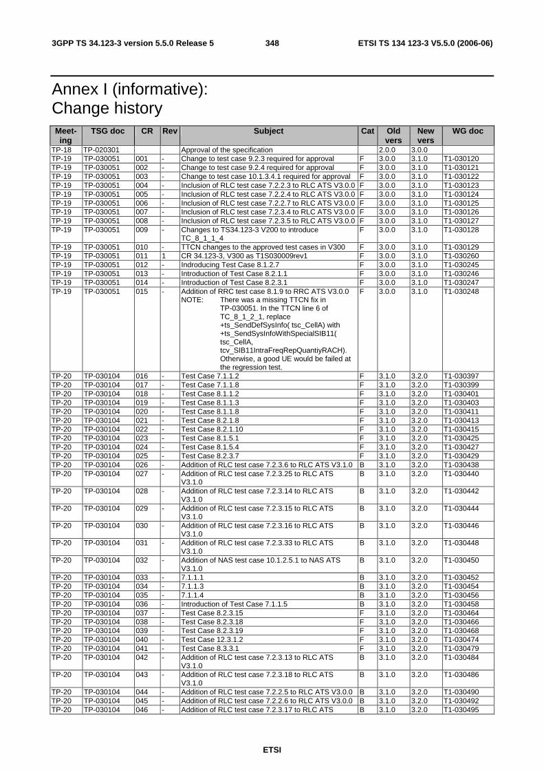
ETSI
ETSI TS 134 123-3 V5.5.0 (2006-06) 3483GPP TS 34.123-3 version 5.5.0 Release 5
Annex I (informative): Change history Meet-ing
TSG doc CR Rev Subject Cat Old vers
New vers
WG doc
TP-18 TP-020301 Approval of the specification 2.0.0 3.0.0 TP-19 TP-030051 001 - Change to test case 9.2.3 required for approval F 3.0.0 3.1.0 T1-030120 TP-19 TP-030051 002 - Change to test case 9.2.4 required for approval F 3.0.0 3.1.0 T1-030121 TP-19 TP-030051 003 - Change to test case 10.1.3.4.1 required for approval F 3.0.0 3.1.0 T1-030122 TP-19 TP-030051 004 - Inclusion of RLC test case 7.2.2.3 to RLC ATS V3.0.0 F 3.0.0 3.1.0 T1-030123 TP-19 TP-030051 005 - Inclusion of RLC test case 7.2.2.4 to RLC ATS V3.0.0 F 3.0.0 3.1.0 T1-030124 TP-19 TP-030051 006 - Inclusion of RLC test case 7.2.2.7 to RLC ATS V3.0.0 F 3.0.0 3.1.0 T1-030125 TP-19 TP-030051 007 - Inclusion of RLC test case 7.2.3.4 to RLC ATS V3.0.0 F 3.0.0 3.1.0 T1-030126 TP-19 TP-030051 008 - Inclusion of RLC test case 7.2.3.5 to RLC ATS V3.0.0 F 3.0.0 3.1.0 T1-030127 TP-19 TP-030051 009 - Changes to TS34.123-3 V200 to introduce
TC_8_1_1_4 F 3.0.0 3.1.0 T1-030128
TP-19 TP-030051 010 - TTCN changes to the approved test cases in V300 F 3.0.0 3.1.0 T1-030129 TP-19 TP-030051 011 1 CR 34.123-3, V300 as T1S030009rev1 F 3.0.0 3.1.0 T1-030260 TP-19 TP-030051 012 - Indroducing Test Case 8.1.2.7 F 3.0.0 3.1.0 T1-030245 TP-19 TP-030051 013 - Introduction of Test Case 8.2.1.1 F 3.0.0 3.1.0 T1-030246 TP-19 TP-030051 014 - Introduction of Test Case 8.2.3.1 F 3.0.0 3.1.0 T1-030247 TP-19 TP-030051 015 - Addition of RRC test case 8.1.9 to RRC ATS V3.0.0
NOTE: There was a missing TTCN fix in TP-030051. In the TTCN line 6 of TC_8_1_2_1, replace +ts_SendDefSysInfo( tsc_CellA) with +ts_SendSysInfoWithSpecialSIB11( tsc_CellA, tcv_SIB11IntraFreqRepQuantiyRACH). Otherwise, a good UE would be failed at the regression test.
F 3.0.0 3.1.0 T1-030248
TP-20 TP-030104 016 - Test Case 7.1.1.2 F 3.1.0 3.2.0 T1-030397 TP-20 TP-030104 017 - Test Case 7.1.1.8 F 3.1.0 3.2.0 T1-030399 TP-20 TP-030104 018 - Test Case 8.1.1.2 F 3.1.0 3.2.0 T1-030401 TP-20 TP-030104 019 - Test Case 8.1.1.3 F 3.1.0 3.2.0 T1-030403 TP-20 TP-030104 020 - Test Case 8.1.1.8 F 3.1.0 3.2.0 T1-030411 TP-20 TP-030104 021 - Test Case 8.2.1.8 F 3.1.0 3.2.0 T1-030413 TP-20 TP-030104 022 - Test Case 8.2.1.10 F 3.1.0 3.2.0 T1-030415 TP-20 TP-030104 023 - Test Case 8.1.5.1 F 3.1.0 3.2.0 T1-030425 TP-20 TP-030104 024 - Test Case 8.1.5.4 F 3.1.0 3.2.0 T1-030427 TP-20 TP-030104 025 - Test Case 8.2.3.7 F 3.1.0 3.2.0 T1-030429 TP-20 TP-030104 026 - Addition of RLC test case 7.2.3.6 to RLC ATS V3.1.0 B 3.1.0 3.2.0 T1-030438 TP-20 TP-030104 027 - Addition of RLC test case 7.2.3.25 to RLC ATS
V3.1.0 B 3.1.0 3.2.0 T1-030440
TP-20 TP-030104 028 - Addition of RLC test case 7.2.3.14 to RLC ATS V3.1.0
B 3.1.0 3.2.0 T1-030442
TP-20 TP-030104 029 - Addition of RLC test case 7.2.3.15 to RLC ATS V3.1.0
B 3.1.0 3.2.0 T1-030444
TP-20 TP-030104 030 - Addition of RLC test case 7.2.3.16 to RLC ATS V3.1.0
B 3.1.0 3.2.0 T1-030446
TP-20 TP-030104 031 - Addition of RLC test case 7.2.3.33 to RLC ATS V3.1.0
B 3.1.0 3.2.0 T1-030448
TP-20 TP-030104 032 - Addition of NAS test case 10.1.2.5.1 to NAS ATS V3.1.0
B 3.1.0 3.2.0 T1-030450
TP-20 TP-030104 033 - 7.1.1.1 B 3.1.0 3.2.0 T1-030452 TP-20 TP-030104 034 - 7.1.1.3 B 3.1.0 3.2.0 T1-030454 TP-20 TP-030104 035 - 7.1.1.4 B 3.1.0 3.2.0 T1-030456 TP-20 TP-030104 036 - Introduction of Test Case 7.1.1.5 B 3.1.0 3.2.0 T1-030458 TP-20 TP-030104 037 - Test Case 8.2.3.15 F 3.1.0 3.2.0 T1-030464 TP-20 TP-030104 038 - Test Case 8.2.3.18 F 3.1.0 3.2.0 T1-030466 TP-20 TP-030104 039 - Test Case 8.2.3.19 F 3.1.0 3.2.0 T1-030468 TP-20 TP-030104 040 - Test Case 12.3.1.2 F 3.1.0 3.2.0 T1-030474 TP-20 TP-030104 041 - Test Case 8.3.3.1 F 3.1.0 3.2.0 T1-030479 TP-20 TP-030104 042 - Addition of RLC test case 7.2.3.13 to RLC ATS
V3.1.0 B 3.1.0 3.2.0 T1-030484
TP-20 TP-030104 043 - Addition of RLC test case 7.2.3.18 to RLC ATS V3.1.0
B 3.1.0 3.2.0 T1-030486
TP-20 TP-030104 044 - Addition of RLC test case 7.2.2.5 to RLC ATS V3.0.0 B 3.1.0 3.2.0 T1-030490 TP-20 TP-030104 045 - Addition of RLC test case 7.2.2.6 to RLC ATS V3.0.0 B 3.1.0 3.2.0 T1-030492 TP-20 TP-030104 046 - Addition of RLC test case 7.2.3.17 to RLC ATS B 3.1.0 3.2.0 T1-030495

ETSI
ETSI TS 134 123-3 V5.5.0 (2006-06) 3493GPP TS 34.123-3 version 5.5.0 Release 5
Meet-ing
TSG doc CR Rev Subject Cat Old vers
New vers
WG doc
V3.0.0 TP-20 TP-030104 047 - Addition of RLC test case 7.2.3.20 to RLC ATS
V3.0.0 B 3.1.0 3.2.0 T1-030496
TP-20 TP-030104 048 - Addition of RLC test case 7.2.3.34 to RLC ATS V3.0.0
B 3.1.0 3.2.0 T1-030498
TP-20 TP-030104 049 - Addition of SM test case 11.1.1.1 to NAS ATS V3.1.0 B 3.1.0 3.2.0 T1-030500 TP-20 TP-030104 050 - Addition of RLC test case 7.2.3.23 to RLC ATS
V3.1.0 B 3.1.0 3.2.0 T1-030535
TP-20 TP-030104 051 - Addition of RLC test case 7.2.3.24 to RLC ATS V3.1.0
B 3.1.0 3.2.0 T1-030537
TP-20 TP-030104 052 - Addition of RLC test case 7.2.3.26 to RLC ATS V3.1.0
B 3.1.0 3.2.0 T1-030539
TP-20 TP-030104 053 - Addition of RLC test case 7.2.3.27 to RLC ATS V3.1.0
B 3.1.0 3.2.0 T1-030541
TP-20 TP-030104 054 - Addition of SM test case 11.3.1 to NAS ATS V3.1.0 B 3.1.0 3.2.0 T1-030576 TP-20 TP-030104 055 - Addition of SM test case 11.3.2 to NAS ATS V3.1.0 B 3.1.0 3.2.0 T1-030577 TP-20 TP-030104 056 - Addition of GMM test case 12.3.1.5 to NAS ATS
V3.1.0 B 3.1.0 3.2.0 T1-030578
TP-20 TP-030104 057 - Addition of GMM test case 12.7 to NAS ATS V3.1.0 B 3.1.0 3.2.0 T1-030580 TP-20 TP-030104 058 - Test Case 8.2.1.9 F 3.1.0 3.2.0 T1-030594 TP-20 TP-030104 059 - Test Case 8.2.3.8 F 3.1.0 3.2.0 T1-030596 TP-20 TP-030104 060 - Test Case 12.3.1.1 F 3.1.0 3.2.0 T1-030614 TP-20 TP-030104 062 - Test Case 12.9.2 F 3.1.0 3.2.0 T1-030626 TP-20 TP-030104 063 - Addition of GMM test case 12.3.2.1 to NAS ATS
V3.1.0 B 3.1.0 3.2.0 T1-030638
TP-20 TP-030104 064 - CR for correction of generic test step in RLC ATS V3.1.0
F 3.1.0 3.2.0 T1-030654
TP-20 TP-030104 065 - ASP Enhancement F 3.1.0 3.2.0 T1-030665 TP-20 TP-030104 066 - Test Case 8.1.2.2 F 3.1.0 3.2.0 T1-030395 TP-20 TP-030104 067 - Test Case 8.1.2.9 F 3.1.0 3.2.0 T1-030396 TP-20 TP-030110 068 - Add new approved test cases in test case list in
Annex A F 3.1.0 3.2.0 --
TP-20 TP-030141 069 - Test Case 8.1.3.3 F 3.1.0 3.2.0 T1-030460 TP-20 - - - Regeneration of RRC and RLC ATS 3.2.0 3.2.1 - TP-21 TP-030194 073 - CR to 34.123-3 R99, Moving baseline from March 02
to March 03 and error corrections F 3.2.1 3.3.0 T1-031242
TP-21 TP-030194 074 - CR to 34.123-3, R99, Update and remove unnecessary PIXIT parameters, so they are aligned with the 3GPP conformance TTCN
F 3.2.1 3.3.0 T1-031278
TP-21 TP-030199 - - Add new approved TTCN test cases in test case list in Annex A
F 3.2.1 3.3.0 -
TP-21 TP-030194 070 - Corrections to Package 1 test cases in RRC ATS v3.2.1 for PS mode
F 3.2.1 3.3.0 T1-031054
TP-21 TP-030194 071 - Corrections to Package 1 test cases in RRC ATS v3.2.1 for Integrity
F 3.2.1 3.3.0 T1-031055
TP-21 TP-030194 072 - Corrections to Package 1 test cases in RRC ATS v3.2.1 for configuration of Radio Bearer -3
F 3.2.1 3.3.0 T1-031140
TP-21 TP-030194 079 - Changes to TS34.123-3 V310 to introduce TC_8_1_1_5
F 3.1.0 3.3.0 T1-030405
TP-21 TP-030194 080 - Changes to TS34.123-3 V310 to introduce TC_8_1_1_6
F 3.1.0 3.3.0 T1-030407
TP-21 TP-030194 084 - Changes to TS34.123-3 V310 to introduce TC_12_2_1_1
F 3.1.0 3.3.0 T1-030423
TP-21 TP-030194 119 - Changes to TS34.123-3 V310 to introduce TC_8_3_4_1
F 3.1.0 3.3.0 T1-030602
TP-21 TP-030194 120 - Changes to TS34.123-3 V310 to introduce TC_8_3_4_2
F 3.1.0 3.3.0 T1-030604
TP-21 TP-030194 121 - Changes to TS34.123-3 V310 to introduce TC_8_3_4_3
F 3.1.0 3.3.0 T1-030606
TP-21 TP-030194 122 - Changes to TS34.123-3 V310 to introduce TC_8_4_1_1
F 3.1.0 3.3.0 T1-030608
TP-21 TP-030194 124 - Changes to TS34.123-3 V310 to introduce TC_12_9_1
F 3.1.0 3.3.0 T1-030624
TP-21 TP-030194 127 - CR to 34.123-3 V310 to introduce test case 7.2.3.19 B 3.1.0 3.3.0 T1-030657 TP-21 TP-030194 128 - CR to 34.123-3 V320 to introduce test case 14.2.13.1 B 3.2.0 3.3.0 T1-030877 TP-21 TP-030194 129 - CR to 34.123-3 V320 to introduce test case 7.2.2.2 B 3.2.0 3.3.0 T1-030879 TP-21 TP-030194 130 - CR to 34.123-3 V320 to introduce test case 7.2.3.2 B 3.2.0 3.3.0 T1-030881 TP-21 TP-030194 131 - Changes to TS34.123-3 V320 to introduce
TC_8_2_3_9 B 3.2.0 3.3.0 T1-030896
TP-21 TP-030194 132 - Changes to TS34.123-3 V320 to introduce TC_7_2_3_21
F 3.2.0 3.3.0 T1-030897
TP-21 TP-030194 133 - Changes to TS34.123-3 V320 to introduce F 3.2.0 3.3.0 T1-030898
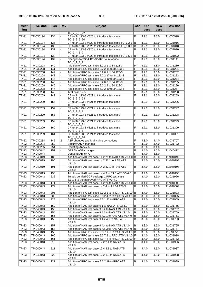
ETSI
ETSI TS 134 123-3 V5.5.0 (2006-06) 3503GPP TS 34.123-3 version 5.5.0 Release 5
Meet-ing
TSG doc CR Rev Subject Cat Old vers
New vers
WG doc
TC_7_2_3_22 TP-21 TP-030194 134 - CR to 34.123-3 V320 to introduce test case
TC_8_2_6_20 F 3.2.1 3.3.0 T1-030928
TP-21 TP-030194 135 - CR to 34.123-3 V320 to introduce test case TC_9.2.1 B 3.2.1 3.3.0 T1-031016 TP-21 TP-030194 136 - CR to 34.123-3 V320 to introduce test case TC_9.3.1 B 3.2.1 3.3.0 T1-031018 TP-21 TP-030194 137 - CR to 34.123-3 V320 to introduce test case
TC_9_4_5_2 B 3.2.1 3.3.0 T1-031020
TP-21 TP-030194 138 - CR to 34.123-3 V320 to introduce test case TC_9.5.2 B 3.2.1 3.3.0 T1-031022 TP-21 TP-030194 139 - Changes to TS34.123-3 V321 to introduce
TC_8_1_1_7 F 3.2.1 3.3.0 T1-031141
TP-21 TP-030208 140 - Addition of RRC test case 8.2.2.1 to 34.123-3 F 3.2.1 3.3.0 T1-031280 TP-21 TP-030208 141 - Addition of RRC test case 8.2.2.11 to 34.123-3 F 3.2.1 3.3.0 T1-031281 TP-21 TP-030208 142 - Addition of RRC test case 8.2.6.1 to 34.123-3 F 3.2.1 3.3.0 T1-031282 TP-21 TP-030208 143 - Addition of RRC test case 8.2.2.17 to 34.123-3 F 3.2.1 3.3.0 T1-031283 TP-21 TP-030208 144 - Addition of RRC test case 8.2.4.10 to 34.123-3 F 3.2.1 3.3.0 T1-031284 TP-21 TP-030208 145 - Addition of RRC test case 8.2.6.7 to 34.123-3 F 3.2.1 3.3.0 T1-031285 TP-21 TP-030208 146 - Addition of RRC test case 8.2.2.8 to 34.123-3 F 3.2.1 3.3.0 T1-031286 TP-21 TP-030208 147 - Addition of RRC test case 8.2.2.10 to 34.123-3 F 3.2.1 3.3.0 T1-031287 TP-21 TP-030208 148 - Test case 12.5 F 3.2.1 3.3.0 T1-031288 TP-21 TP-030209 149 - CR to 34.123-3 V321 to introduce test case
TC_8_2_2_23 F 3.2.1 3.3.0 T1-031289
TP-21 TP-030209 156 - CR to 34.123-3 V321 to introduce test case TC_8_2_6_19
F 3.2.1 3.3.0 T1-031296
TP-21 TP-030209 157 - CR to 34.123-3 V321 to introduce test case TC_8_2_2_7
F 3.2.1 3.3.0 T1-031297
TP-21 TP-030209 158 - CR to 34.123-3 V321 to introduce test case TC_8_2_2_9
F 3.2.1 3.3.0 T1-031298
TP-21 TP-030209 159 - CR to 34.123-3 V321 to introduce test case TC_8_3_1_11
F 3.2.1 3.3.0 T1-031299
TP-21 TP-030209 160 - CR to 34.123-3 V321 to introduce test case TC_8_2_6_8
F 3.2.1 3.3.0 T1-031300
TP-21 TP-030209 161 - CR to 34.123-3 V321 to introduce test case TC_8_4_1_16
F 3.2.1 3.3.0 T1-031301
TP-22 TP-030284 142 2 ASP changes and MMI string corrections F 3.3.0 3.4.0 T1-031707 TP-22 TP-030284 252 - Security ASP changes F 3.3.0 3.4.0 T1-031732 TP-22 TP-030285 251 - Updating Annex A F 3.3.0 3.4.0 - TP-23 TP-040042 151 - GERAN ASP changes F 3.4.0 3.5.0 T1-040412 TP-23 TP-040044 - - Updating Annex A F 3.4.0 3.5.0 - TP-23 TP-040019 189 Addition of RAB test case 14.2.29 to RAB ATS V3.4.0 B 3.4.0 3.5.0 T1s040199 TP-23 TP-040019 190 Addition of RAB test case 14.2.31.1 to RAB ATS
V3.4.0 B 3.4.0 3.5.0 T1s040198
TP-23 TP-040019 191 Addition of RAB test case 14.2.32.1 to RAB ATS V3.4.0
B 3.4.0 3.5.0 T1s040197
TP-23 TP-040019 193 Addition of RAB test case 14.4.3 to RAB ATS V3.4.0 B 3.4.0 3.5.0 T1s040196 TP-23 TP-040043 232 To add verified GCF package 1 RRC test case
8.3.1.3 to the approved RRC ATS V3.4.0 3.4.0 3.5.0 T1-031926
TP-23 TP-040043 171 Addition of RAB test case 14.2.26 to RAB ATS V3.4.0 B 3.4.0 3.5.0 T1s040002 TP-23 TP-040043 172 Addition of RAB test case 14.2.4 to TS 34.123-3,
V3.4.0 B 3.4.0 3.5.0 T1s040004
TP-23 TP-040043 205 Addition of RRC test case 8.3.2.1 to RRC ATS V3.4.0 B 3.4.0 3.5.0 T1-031823 TP-23 TP-040043 206 Addition of RRC test case 8.3.2.4 to RRC ATS V3.4.0 B 3.3.0 3.5.0 T1-031825 TP-23 TP-040043 224 Addition of RRC test case 8.3.1.31 to RRC ATS
V3.4.0 B 3.3.0 3.5.0 T1-031909
TP-23 TP-040043 152 Addition of NAS test case 9.1 to NAS ATS V3.4.0 B 3.3.0 3.5.0 T1-031755 TP-23 TP-040043 153 Addition of NAS test case 9.2.2 to NAS ATS V3.4.0 B 3.3.0 3.5.0 T1-031757 TP-23 TP-040043 154 Addition of NAS test case 9.4.1 to NAS ATS V3.4.0 B 3.3.0 3.5.0 T1-031759 TP-23 TP-040043 155 Addition of NAS test case 9.4.2.1 to NAS ATS V3.4.0 B 3.3.0 3.5.0 T1-031761 TP-23 TP-040043 156 Addition of NAS test case 9.4.2.4.1 to NAS ATS
V3.4.0 B 3.3.0 3.5.0 T1-031763
TP-23 TP-040043 157 Addition of NAS test case 9.4.4 to NAS ATS V3.4.0 B 3.3.0 3.5.0 T1-031765 TP-23 TP-040043 158 Addition of NAS test case 9.4.5.3 to NAS ATS V3.4.0 B 3.3.0 3.5.0 T1-031767 TP-23 TP-040043 159 Addition of RRC test case 8.3.7.1 to RRC ATS V3.4.0 B 3.3.0 3.5.0 T1-031771 TP-23 TP-040043 160 Addition of RRC test case 8.3.7.2 to RRC ATS V3.4.0 F 3.4.0 3.5.0 T1-031918 TP-23 TP-040043 161 Addition of RRC test case 8.3.7.4 to RRC ATS V3.4.0 F 3.4.0 3.5.0 T1-031772 TP-23 TP-040043 210 Addition of NAS test case 12.2.2.1 to NAS ATS
V3.4.0 F 3.4.0 3.5.0 T1-031936
TP-23 TP-040043 211 Addition of NAS test case 12.4.3.1 to NAS ATS V3.4.0
B 3.4.0 3.5.0 T1-031937
TP-23 TP-040043 222 Addition of NAS test case 12.2.1.3 to NAS ATS V3.4.0
B 3.4.0 3.5.0 T1-031938
TP-23 TP-040043 221 Addition of RRC test case 8.2.2.19 to RRC ATS V3.4.0
B 3.4.0 3.5.0 T1-031939

ETSI
ETSI TS 134 123-3 V5.5.0 (2006-06) 3513GPP TS 34.123-3 version 5.5.0 Release 5
Meet-ing
TSG doc CR Rev Subject Cat Old vers
New vers
WG doc
TP-23 TP-040043 220 Addition of RRC test case 8.4.1.17 to RRC ATS V3.4.0
B 3.4.0 3.5.0 T1-031940
TP-23 TP-040043 162 Addition of NAS test case 12.2.1.7 to NAS ATS V3.4.0
B 3.4.0 3.5.0 T1s040029
TP-23 TP-040043 163 Addition of RAB test case 14.2.27 to RAB ATS V3.4.0 B 3.4.0 3.5.0 T1s040033 TP-23 TP-040043 164 Introducing test case 12_6_1_1 to NASv330 B 3.4.0 3.5.0 T1-031745 TP-23 TP-040043 184 Introducing test case 8.3.1.1 to RRCv340 F 3.3.0 3.5.0 T1-031733 TP-23 TP-040043 165 Introducing test case 8.2.4.3 to RRCv330 F 3.4.0 3.5.0 T1-031747 TP-23 TP-040043 166 Introducing test case 8.2.4.4 to RRCv330 F 3.3.0 3.5.0 T1-031749 TP-23 TP-040043 192 Introducing test case 8.3.1.22 to RRCv340 F 3.3.0 3.5.0 T1-031797 TP-23 TP-040043 195 Introducing test case 8.2.2.18 to RRCv340 F 3.4.0 3.5.0 T1-031932 TP-23 TP-040043 234 Introducing test case 12_4_2_1 to NASv340 F 3.4.0 3.5.0 T1-031930 TP-23 TP-040043 233 Introducing test case 8.3.1.4 to RRCv340 F 3.4.0 3.5.0 T1s040087 TP-23 TP-040043 216 Revised CR for Changes to Introducing test case
8.2.6.9 required for approvalto RRCv340 F 3.4.0 3.5.0 T1s040088
TP-23 TP-040043 167 Introduction of Package 2 test case 8.3.1.21 F 3.4.0 3.5.0 T1s040049 TP-23 TP-040043 207 Addition of RRC test case 8.3.2.7 to RRC ATS V3.4.0 F 3.4.0 3.5.0 T1-031827 TP-23 TP-040043 168 Addition of NAS test case 9.4.2.2.1 to NAS ATS
V3.4.0 B 3.3.0 T1s040025
TP-23 TP-040043 169 Addition of NAS test case 9.4.2.2.2 to NAS ATS V3.4.0
B 3.4.0 3.5.0 T1s040027
TP-23 TP-040043 170 Addition of NAS test case 9.4.9 to NAS ATS V3.4.0 B 3.4.0 3.5.0 T1s040014 TP-23 TP-040043 171 Addition of NAS test case 9.4.2.5 to NAS ATS V3.4.0 B 3.4.0 3.5.0 T1s040082 TP-23 TP-040043 172 Correction to RRC Package 1 TC 8.2.1.8 and 8.2.1.9
for the mismatch between Radio Bearer setup and PDP context Activation Accept message
B 3.4.0 3.5.0 T1s040071
TP-23 TP-040043 226 Validation of TMSI status in ATTACH REQUEST message for tc 12.3.1.5
F 3.4.0 3.5.0 T1-031913
TP-23 TP-040043 227 Validation of optional old PTMSI signature in ATTACH REQUEST message for tc 12.2.1.1
F 3.3.0 3.5.0 T1-031914
TP-23 TP-040043 173 Incorrect timer poll value used for SS RLC transmit entity in tcs 8.2.1.8, 8.2.1.9 (Revision of T1-031782)
F 3.3.0 3.5.0 T1-031842
TP-23 TP-040043 174 Correction of Poll bit checking in tc 7.2.3.13 (Revision of T1-031839)
F 3.3.0 3.5.0 T1-031921
TP-23 TP-040043 230 Validation of CS CKSN in paging response in tc 9.2.1 F 3.3.0 3.5.0 T1-031922 TP-23 TP-040043 175 Modification to Radio Bearer Release message in tc
8.2.3.18 and 8.2.3.19 F 3.3.0 3.5.0 T1-031924
TP-23 TP-040043 176 Maximum allowed UL TX power should not be present in tcs 8.2.2.8, 8.2.2.9 and 8.2.2.23
F 3.3.0 3.5.0 T1-031925
TP-23 TP-040043 177 New C-RNTI should not be present in tc 8.2.6.20 F 3.3.0 3.5.0 T1-031787 TP-23 TP-040043 178 Unnecessary waiting time for reconfiguration in tc
8.2.2.23 F 3.3.0 3.5.0 T1-031788
TP-23 TP-040043 179 Modification to validate TI flag and TI value in TCs 11.3.1 and 11.3.2
F 3.3.0 3.5.0 T1-031795
TP-23 TP-040043 180 Change U-RNTI and remove UTRAN DRX cycle length coefficient tc 8.3.3.1
F 3.3.0 3.5.0 T1-031841
TP-23 TP-040043 181 Corrections of Status PDU checking in tc 7.2.3.34 F 3.3.0 3.5.0 T1-031786 TP-23 TP-040043 182 Correction of number of negatively acknowledged
PDUs in tc 7.2.3.16 F 3.3.0 3.5.0 T1-031789
TP-23 TP-040043 183 Correction of sequence number checking and Verdict assessments in tc 7.2.3.17
F 3.3.0 3.5.0 T1-031790
TP-23 TP-040043 184 Poll Bit and Status PDU content checking in tc 7.2.3.14
F 3.3.0 3.5.0 T1-031791
TP-23 TP-040043 185 Additional verdicts assigned in tc 7.2.3.20 F 3.3.0 3.5.0 T1-031792 TP-23 TP-040043 186 SERVICE ACCEPT message NOT to be sent to UE
in GMM idle state in tc 11.3.1 and 11.3.2 F 3.3.0 3.5.0 T1-031794
TP-23 TP-040043 187 Change to performing integrity protection in tc 12.2.1.1
F 3.3.0 3.5.0 T1-031778
TP-23 TP-040043 188 Correction of Poll bit checking in tc 7.2.3.18 F 3.3.0 3.5.0 T1-031781 TP-23 - - Editorial clean-up by ETSI 3.5.0 3.5.1 - TP-23 - - Sections 8.3.28 - 8.3.31 were misplaced 3.5.1 3.5.2 - TP-24 TP-040117 233 Clarification of Section 8.5.1 Authentication: Explicitly
stating that Authentication after IDT is an optional/dependent procedure.
F 3.5.2 3.6.0 T1-040761
TP-24 TP-040117 234 GERAN generic procedures and TTCN encoding rules for CSN.1 specific encoding
F 3.5.2 3.6.0 T1-040940
TP-24 TP-040123 359 Updating Annex A F 3.5.2 3.6.0 - TP-24 TP-040118 255 Addition of MAC test case 7.1.3.1 to MAC ATS V3.5.1 B 3.5.1 3.6.0 T1s040295
TP-24 TP-040118 256 Addition of RAB test case 14.2.49.1 to RAB ATS
V3.5.1 B 3.5.1 3.6.0 T1s040254
TP-24 TP-040118 257 Addition of GCF P1 test case 8.4.1.2 to RRC ATS
V3.5.1 B 3.5.1 3.6.0 T1s040252
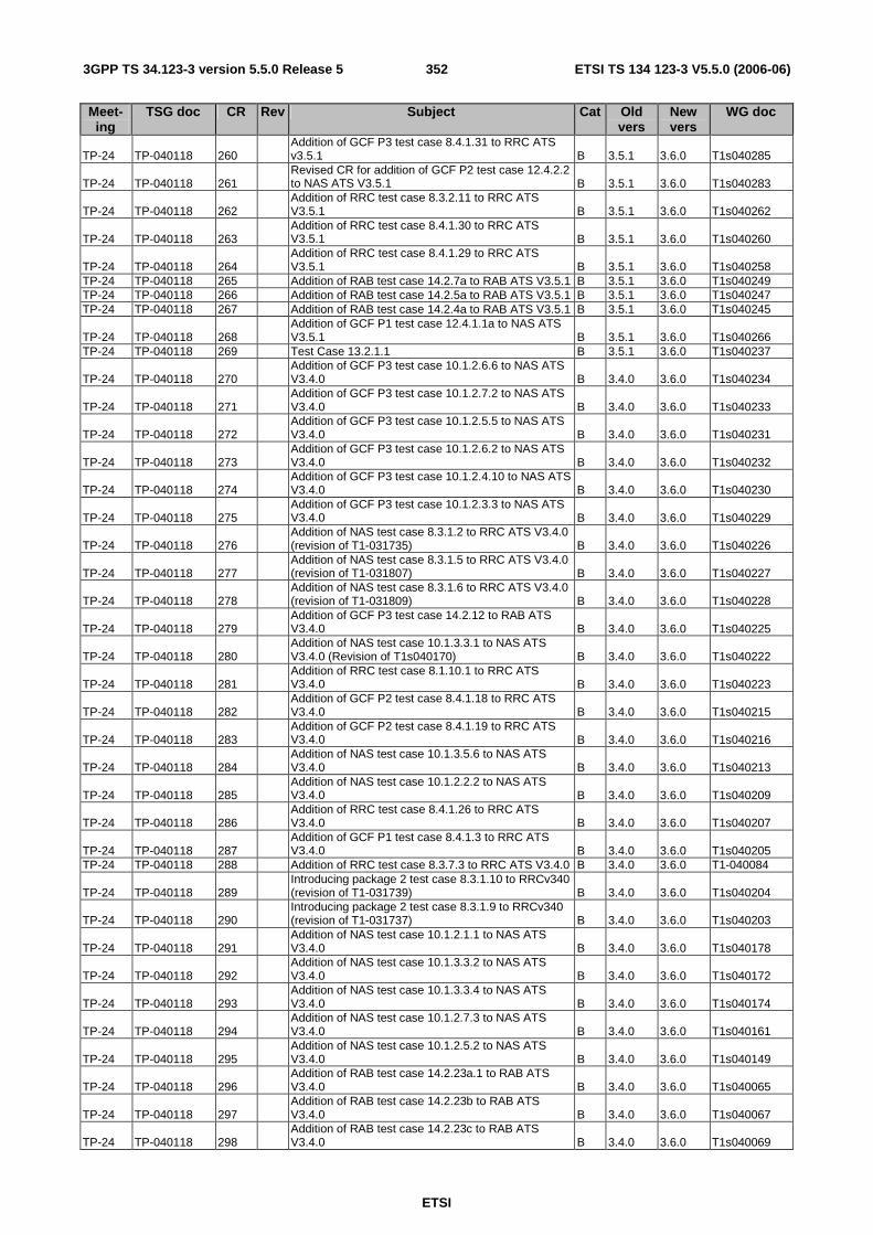
ETSI
ETSI TS 134 123-3 V5.5.0 (2006-06) 3523GPP TS 34.123-3 version 5.5.0 Release 5
Meet-ing
TSG doc CR Rev Subject Cat Old vers
New vers
WG doc
TP-24 TP-040118 260 Addition of GCF P3 test case 8.4.1.31 to RRC ATS
v3.5.1 B 3.5.1 3.6.0 T1s040285
TP-24 TP-040118 261 Revised CR for addition of GCF P2 test case 12.4.2.2
to NAS ATS V3.5.1 B 3.5.1 3.6.0 T1s040283
TP-24 TP-040118 262 Addition of RRC test case 8.3.2.11 to RRC ATS
V3.5.1 B 3.5.1 3.6.0 T1s040262
TP-24 TP-040118 263 Addition of RRC test case 8.4.1.30 to RRC ATS
V3.5.1 B 3.5.1 3.6.0 T1s040260
TP-24 TP-040118 264 Addition of RRC test case 8.4.1.29 to RRC ATS
V3.5.1 B 3.5.1 3.6.0 T1s040258 TP-24 TP-040118 265 Addition of RAB test case 14.2.7a to RAB ATS V3.5.1 B 3.5.1 3.6.0 T1s040249 TP-24 TP-040118 266 Addition of RAB test case 14.2.5a to RAB ATS V3.5.1 B 3.5.1 3.6.0 T1s040247 TP-24 TP-040118 267 Addition of RAB test case 14.2.4a to RAB ATS V3.5.1 B 3.5.1 3.6.0 T1s040245
TP-24 TP-040118 268 Addition of GCF P1 test case 12.4.1.1a to NAS ATS
V3.5.1 B 3.5.1 3.6.0 T1s040266 TP-24 TP-040118 269 Test Case 13.2.1.1 B 3.5.1 3.6.0 T1s040237
TP-24 TP-040118 270 Addition of GCF P3 test case 10.1.2.6.6 to NAS ATS
V3.4.0 B 3.4.0 3.6.0 T1s040234
TP-24 TP-040118 271 Addition of GCF P3 test case 10.1.2.7.2 to NAS ATS
V3.4.0 B 3.4.0 3.6.0 T1s040233
TP-24 TP-040118 272 Addition of GCF P3 test case 10.1.2.5.5 to NAS ATS
V3.4.0 B 3.4.0 3.6.0 T1s040231
TP-24 TP-040118 273 Addition of GCF P3 test case 10.1.2.6.2 to NAS ATS
V3.4.0 B 3.4.0 3.6.0 T1s040232
TP-24 TP-040118 274 Addition of GCF P3 test case 10.1.2.4.10 to NAS ATS
V3.4.0 B 3.4.0 3.6.0 T1s040230
TP-24 TP-040118 275 Addition of GCF P3 test case 10.1.2.3.3 to NAS ATS
V3.4.0 B 3.4.0 3.6.0 T1s040229
TP-24 TP-040118 276 Addition of NAS test case 8.3.1.2 to RRC ATS V3.4.0
(revision of T1-031735) B 3.4.0 3.6.0 T1s040226
TP-24 TP-040118 277 Addition of NAS test case 8.3.1.5 to RRC ATS V3.4.0
(revision of T1-031807) B 3.4.0 3.6.0 T1s040227
TP-24 TP-040118 278 Addition of NAS test case 8.3.1.6 to RRC ATS V3.4.0
(revision of T1-031809) B 3.4.0 3.6.0 T1s040228
TP-24 TP-040118 279 Addition of GCF P3 test case 14.2.12 to RAB ATS
V3.4.0 B 3.4.0 3.6.0 T1s040225
TP-24 TP-040118 280 Addition of NAS test case 10.1.3.3.1 to NAS ATS
V3.4.0 (Revision of T1s040170) B 3.4.0 3.6.0 T1s040222
TP-24 TP-040118 281 Addition of RRC test case 8.1.10.1 to RRC ATS
V3.4.0 B 3.4.0 3.6.0 T1s040223
TP-24 TP-040118 282 Addition of GCF P2 test case 8.4.1.18 to RRC ATS
V3.4.0 B 3.4.0 3.6.0 T1s040215
TP-24 TP-040118 283 Addition of GCF P2 test case 8.4.1.19 to RRC ATS
V3.4.0 B 3.4.0 3.6.0 T1s040216
TP-24 TP-040118 284 Addition of NAS test case 10.1.3.5.6 to NAS ATS
V3.4.0 B 3.4.0 3.6.0 T1s040213
TP-24 TP-040118 285 Addition of NAS test case 10.1.2.2.2 to NAS ATS
V3.4.0 B 3.4.0 3.6.0 T1s040209
TP-24 TP-040118 286 Addition of RRC test case 8.4.1.26 to RRC ATS
V3.4.0 B 3.4.0 3.6.0 T1s040207
TP-24 TP-040118 287 Addition of GCF P1 test case 8.4.1.3 to RRC ATS
V3.4.0 B 3.4.0 3.6.0 T1s040205 TP-24 TP-040118 288 Addition of RRC test case 8.3.7.3 to RRC ATS V3.4.0 B 3.4.0 3.6.0 T1-040084
TP-24 TP-040118 289 Introducing package 2 test case 8.3.1.10 to RRCv340
(revision of T1-031739) B 3.4.0 3.6.0 T1s040204
TP-24 TP-040118 290 Introducing package 2 test case 8.3.1.9 to RRCv340
(revision of T1-031737) B 3.4.0 3.6.0 T1s040203
TP-24 TP-040118 291 Addition of NAS test case 10.1.2.1.1 to NAS ATS
V3.4.0 B 3.4.0 3.6.0 T1s040178
TP-24 TP-040118 292 Addition of NAS test case 10.1.3.3.2 to NAS ATS
V3.4.0 B 3.4.0 3.6.0 T1s040172
TP-24 TP-040118 293 Addition of NAS test case 10.1.3.3.4 to NAS ATS
V3.4.0 B 3.4.0 3.6.0 T1s040174
TP-24 TP-040118 294 Addition of NAS test case 10.1.2.7.3 to NAS ATS
V3.4.0 B 3.4.0 3.6.0 T1s040161
TP-24 TP-040118 295 Addition of NAS test case 10.1.2.5.2 to NAS ATS
V3.4.0 B 3.4.0 3.6.0 T1s040149
TP-24 TP-040118 296 Addition of RAB test case 14.2.23a.1 to RAB ATS
V3.4.0 B 3.4.0 3.6.0 T1s040065
TP-24 TP-040118 297 Addition of RAB test case 14.2.23b to RAB ATS
V3.4.0 B 3.4.0 3.6.0 T1s040067
TP-24 TP-040118 298 Addition of RAB test case 14.2.23c to RAB ATS
V3.4.0 B 3.4.0 3.6.0 T1s040069
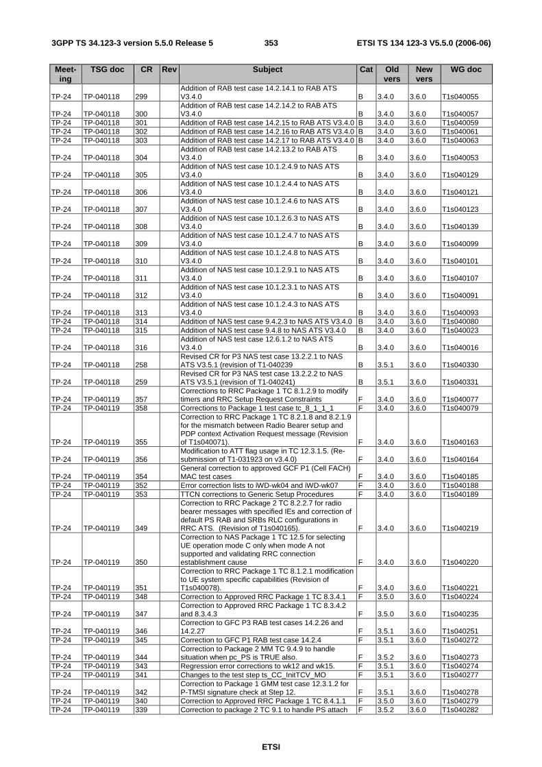
ETSI
ETSI TS 134 123-3 V5.5.0 (2006-06) 3533GPP TS 34.123-3 version 5.5.0 Release 5
Meet-ing
TSG doc CR Rev Subject Cat Old vers
New vers
WG doc
TP-24 TP-040118 299 Addition of RAB test case 14.2.14.1 to RAB ATS
V3.4.0 B 3.4.0 3.6.0 T1s040055
TP-24 TP-040118 300 Addition of RAB test case 14.2.14.2 to RAB ATS
V3.4.0 B 3.4.0 3.6.0 T1s040057 TP-24 TP-040118 301 Addition of RAB test case 14.2.15 to RAB ATS V3.4.0 B 3.4.0 3.6.0 T1s040059 TP-24 TP-040118 302 Addition of RAB test case 14.2.16 to RAB ATS V3.4.0 B 3.4.0 3.6.0 T1s040061 TP-24 TP-040118 303 Addition of RAB test case 14.2.17 to RAB ATS V3.4.0 B 3.4.0 3.6.0 T1s040063
TP-24 TP-040118 304 Addition of RAB test case 14.2.13.2 to RAB ATS
V3.4.0 B 3.4.0 3.6.0 T1s040053
TP-24 TP-040118 305 Addition of NAS test case 10.1.2.4.9 to NAS ATS
V3.4.0 B 3.4.0 3.6.0 T1s040129
TP-24 TP-040118 306 Addition of NAS test case 10.1.2.4.4 to NAS ATS
V3.4.0 B 3.4.0 3.6.0 T1s040121
TP-24 TP-040118 307 Addition of NAS test case 10.1.2.4.6 to NAS ATS
V3.4.0 B 3.4.0 3.6.0 T1s040123
TP-24 TP-040118 308 Addition of NAS test case 10.1.2.6.3 to NAS ATS
V3.4.0 B 3.4.0 3.6.0 T1s040139
TP-24 TP-040118 309 Addition of NAS test case 10.1.2.4.7 to NAS ATS
V3.4.0 B 3.4.0 3.6.0 T1s040099
TP-24 TP-040118 310 Addition of NAS test case 10.1.2.4.8 to NAS ATS
V3.4.0 B 3.4.0 3.6.0 T1s040101
TP-24 TP-040118 311 Addition of NAS test case 10.1.2.9.1 to NAS ATS
V3.4.0 B 3.4.0 3.6.0 T1s040107
TP-24 TP-040118 312 Addition of NAS test case 10.1.2.3.1 to NAS ATS
V3.4.0 B 3.4.0 3.6.0 T1s040091
TP-24 TP-040118 313 Addition of NAS test case 10.1.2.4.3 to NAS ATS
V3.4.0 B 3.4.0 3.6.0 T1s040093 TP-24 TP-040118 314 Addition of NAS test case 9.4.2.3 to NAS ATS V3.4.0 B 3.4.0 3.6.0 T1s040080 TP-24 TP-040118 315 Addition of NAS test case 9.4.8 to NAS ATS V3.4.0 B 3.4.0 3.6.0 T1s040023
TP-24 TP-040118 316 Addition of NAS test case 12.6.1.2 to NAS ATS
V3.4.0 B 3.4.0 3.6.0 T1s040016
TP-24 TP-040118 258 Revised CR for P3 NAS test case 13.2.2.1 to NAS
ATS V3.5.1 (revision of T1-040239 B 3.5.1 3.6.0 T1s040330
TP-24 TP-040118 259 Revised CR for P3 NAS test case 13.2.2.2 to NAS
ATS V3.5.1 (revision of T1-040241) B 3.5.1 3.6.0 T1s040331
TP-24 TP-040119 357 Corrections to RRC Package 1 TC 8.1.2.9 to modify
timers and RRC Setup Request Constraints F 3.4.0 3.6.0 T1s040077 TP-24 TP-040119 358 Corrections to Package 1 test case tc_8_1_1_1 F 3.4.0 3.6.0 T1s040079
TP-24 TP-040119 355
Correction to RRC Package 1 TC 8.2.1.8 and 8.2.1.9 for the mismatch between Radio Bearer setup and PDP context Activation Request message (Revision of T1s040071). F 3.4.0 3.6.0 T1s040163
TP-24 TP-040119 356 Modification to ATT flag usage in TC 12.3.1.5. (Re-
submission of T1-031923 on v3.4.0) F 3.4.0 3.6.0 T1s040164
TP-24 TP-040119 354 General correction to approved GCF P1 (Cell FACH)
MAC test cases F 3.4.0 3.6.0 T1s040185 TP-24 TP-040119 352 Error correction lists to iWD-wk04 and iWD-wk07 F 3.4.0 3.6.0 T1s040188 TP-24 TP-040119 353 TTCN corrections to Generic Setup Procedures F 3.4.0 3.6.0 T1s040189
TP-24 TP-040119 349
Correction to RRC Package 2 TC 8.2.2.7 for radio bearer messages with specified IEs and correction of default PS RAB and SRBs RLC configurations in RRC ATS. (Revision of T1s040165). F 3.4.0 3.6.0 T1s040219
TP-24 TP-040119 350
Correction to NAS Package 1 TC 12.5 for selecting UE operation mode C only when mode A not supported and validating RRC connection establishment cause F 3.4.0 3.6.0 T1s040220
TP-24 TP-040119 351
Correction to RRC Package 1 TC 8.1.2.1 modification to UE system specific capabilities (Revision of T1s040078). F 3.4.0 3.6.0 T1s040221
TP-24 TP-040119 348 Correction to Approved RRC Package 1 TC 8.3.4.1 F 3.5.0 3.6.0 T1s040224
TP-24 TP-040119 347 Correction to Approved RRC Package 1 TC 8.3.4.2
and 8.3.4.3 F 3.5.0 3.6.0 T1s040235
TP-24 TP-040119 346 Correction to GFC P3 RAB test cases 14.2.26 and
14.2.27 F 3.5.1 3.6.0 T1s040251 TP-24 TP-040119 345 Correction to GFC P1 RAB test case 14.2.4 F 3.5.1 3.6.0 T1s040272
TP-24 TP-040119 344 Correction to Package 2 MM TC 9.4.9 to handle
situation when pc_PS is TRUE also. F 3.5.2 3.6.0 T1s040273 TP-24 TP-040119 343 Regression error corrections to wk12 and wk15. F 3.5.1 3.6.0 T1s040274 TP-24 TP-040119 341 Changes to the test step ts_CC_InitTCV_MO F 3.5.1 3.6.0 T1s040277
TP-24 TP-040119 342 Correction to Package 1 GMM test case 12.3.1.2 for
P-TMSI signature check at Step 12. F 3.5.1 3.6.0 T1s040278 TP-24 TP-040119 340 Correction to Approved RRC Package 1 TC 8.4.1.1 F 3.5.0 3.6.0 T1s040279 TP-24 TP-040119 339 Correction to package 2 TC 9.1 to handle PS attach F 3.5.2 3.6.0 T1s040282
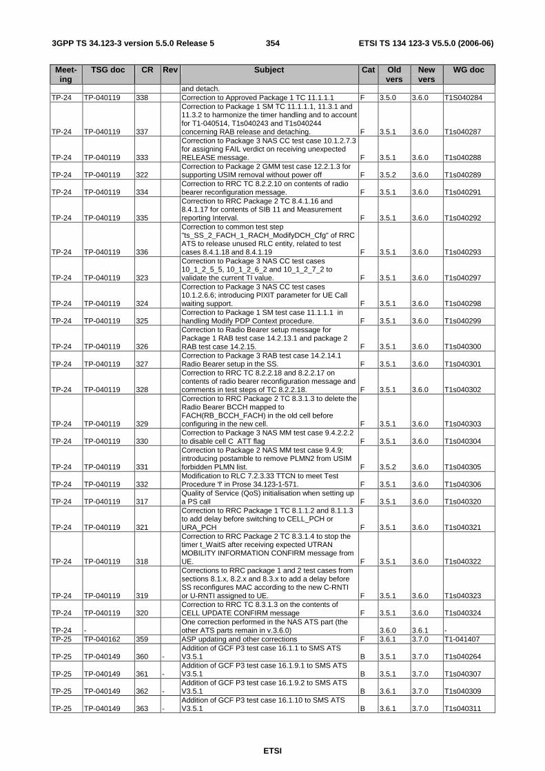
ETSI
ETSI TS 134 123-3 V5.5.0 (2006-06) 3543GPP TS 34.123-3 version 5.5.0 Release 5
Meet-ing
TSG doc CR Rev Subject Cat Old vers
New vers
WG doc
and detach. TP-24 TP-040119 338 Correction to Approved Package 1 TC 11.1.1.1 F 3.5.0 3.6.0 T1S040284
TP-24 TP-040119 337
Correction to Package 1 SM TC 11.1.1.1, 11.3.1 and 11.3.2 to harmonize the timer handling and to account for T1-040514, T1s040243 and T1s040244 concerning RAB release and detaching. F 3.5.1 3.6.0 T1s040287
TP-24 TP-040119 333
Correction to Package 3 NAS CC test case 10.1.2.7.3 for assigning FAIL verdict on receiving unexpected RELEASE message. F 3.5.1 3.6.0 T1s040288
TP-24 TP-040119 322 Correction to Package 2 GMM test case 12.2.1.3 for
supporting USIM removal without power off F 3.5.2 3.6.0 T1s040289
TP-24 TP-040119 334 Correction to RRC TC 8.2.2.10 on contents of radio
bearer reconfiguration message. F 3.5.1 3.6.0 T1s040291
TP-24 TP-040119 335
Correction to RRC Package 2 TC 8.4.1.16 and 8.4.1.17 for contents of SIB 11 and Measurement reporting Interval. F 3.5.1 3.6.0 T1s040292
TP-24 TP-040119 336
Correction to common test step "ts_SS_2_FACH_1_RACH_ModifyDCH_Cfg" of RRC ATS to release unused RLC entity, related to test cases 8.4.1.18 and 8.4.1.19 F 3.5.1 3.6.0 T1s040293
TP-24 TP-040119 323
Correction to Package 3 NAS CC test cases 10_1_2_5_5, 10_1_2_6_2 and 10_1_2_7_2 to validate the current TI value. F 3.5.1 3.6.0 T1s040297
TP-24 TP-040119 324
Correction to Package 3 NAS CC test cases 10.1.2.6.6; introducing PIXIT parameter for UE Call waiting support. F 3.5.1 3.6.0 T1s040298
TP-24 TP-040119 325 Correction to Package 1 SM test case 11.1.1.1 in
handling Modify PDP Context procedure. F 3.5.1 3.6.0 T1s040299
TP-24 TP-040119 326
Correction to Radio Bearer setup message for Package 1 RAB test case 14.2.13.1 and package 2 RAB test case 14.2.15. F 3.5.1 3.6.0 T1s040300
TP-24 TP-040119 327 Correction to Package 3 RAB test case 14.2.14.1
Radio Bearer setup in the SS. F 3.5.1 3.6.0 T1s040301
TP-24 TP-040119 328
Correction to RRC TC 8.2.2.18 and 8.2.2.17 on contents of radio bearer reconfiguration message and comments in test steps of TC 8.2.2.18. F 3.5.1 3.6.0 T1s040302
TP-24 TP-040119 329
Correction to RRC Package 2 TC 8.3.1.3 to delete the Radio Bearer BCCH mapped to FACH(RB_BCCH_FACH) in the old cell before configuring in the new cell. F 3.5.1 3.6.0 T1s040303
TP-24 TP-040119 330 Correction to Package 3 NAS MM test case 9.4.2.2.2
to disable cell C ATT flag F 3.5.1 3.6.0 T1s040304
TP-24 TP-040119 331
Correction to Package 2 NAS MM test case 9.4.9; introducing postamble to remove PLMN2 from USIM forbidden PLMN list. F 3.5.2 3.6.0 T1s040305
TP-24 TP-040119 332 Modification to RLC 7.2.3.33 TTCN to meet Test
Procedure 'f' in Prose 34.123-1-571. F 3.5.1 3.6.0 T1s040306
TP-24 TP-040119 317 Quality of Service (QoS) initialisation when setting up
a PS call F 3.5.1 3.6.0 T1s040320
TP-24 TP-040119 321
Correction to RRC Package 1 TC 8.1.1.2 and 8.1.1.3 to add delay before switching to CELL_PCH or URA_PCH F 3.5.1 3.6.0 T1s040321
TP-24 TP-040119 318
Correction to RRC Package 2 TC 8.3.1.4 to stop the timer t_WaitS after receiving expected UTRAN MOBILITY INFORMATION CONFIRM message from UE. F 3.5.1 3.6.0 T1s040322
TP-24 TP-040119 319
Corrections to RRC package 1 and 2 test cases from sections 8.1.x, 8.2.x and 8.3.x to add a delay before SS reconfigures MAC according to the new C-RNTI or U-RNTI assigned to UE. F 3.5.1 3.6.0 T1s040323
TP-24 TP-040119 320 Correction to RRC TC 8.3.1.3 on the contents of
CELL UPDATE CONFIRM message F 3.5.1 3.6.0 T1s040324
TP-24 - One correction performed in the NAS ATS part (the
other ATS parts remain in v.3.6.0) 3.6.0 3.6.1 - TP-25 TP-040162 359 ASP updating and other corrections F 3.6.1 3.7.0 T1-041407
TP-25 TP-040149 360 - Addition of GCF P3 test case 16.1.1 to SMS ATS V3.5.1 B 3.5.1 3.7.0 T1s040264
TP-25 TP-040149 361 - Addition of GCF P3 test case 16.1.9.1 to SMS ATS V3.5.1 B 3.5.1 3.7.0 T1s040307
TP-25 TP-040149 362 - Addition of GCF P3 test case 16.1.9.2 to SMS ATS V3.5.1 B 3.6.1 3.7.0 T1s040309
TP-25 TP-040149 363 - Addition of GCF P3 test case 16.1.10 to SMS ATS V3.5.1 B 3.6.1 3.7.0 T1s040311
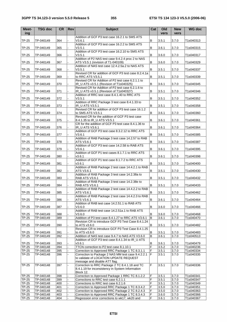
ETSI
ETSI TS 134 123-3 V5.5.0 (2006-06) 3553GPP TS 34.123-3 version 5.5.0 Release 5
Meet-ing
TSG doc CR Rev Subject Cat Old vers
New vers
WG doc
TP-25 TP-040149 364 - Addition of GCF P3 test case 16.2.1 to SMS ATS V3.6.1 B 3.5.1 3.7.0 T1s040313
TP-25 TP-040149 365 - Addition of GCF P3 test case 16.2.2 to SMS ATS V3.5.1 B 3.6.1 3.7.0 T1s040315
TP-25 TP-040149 366 - Addition of GCF P3 test case 16.2.10 to SMS ATS V3.5.1 B 3.6.0 3.7.0 T1s040317
TP-25 TP-040149 367 - Addition of P2 NAS test case 9.4.2.4 proc 2 to NAS ATS V3.5.1 (revision of T1-040109) B 3.6.0 3.7.0 T1s040329
TP-25 TP-040149 368 - Addition of NAS test case 12.4.2.5a.2 to NAS ATS V3.5.1 B 3.5.1 3.7.0 T1s040337
TP-25 TP-040149 369 - Revised CR for addition of GCF P3 test case 8.2.4.1a to RRC ATS V3.5.1 B 3.5.1 3.7.0 T1s040339
TP-25 TP-040149 370 - Revised CR for Addition of P2 test case 6.2.1.1 to IR_U ATS v3.5.1 (Revision of T1s040325) B 3.6.1 3.7.0 T1s040345
TP-25 TP-040149 371 - Revised CR for Addition of P2 test case 6.2.1.6 to IR_U ATS v3.5.1 (Revision of T1s040327) B 3.5.1 3.7.0 T1s040346
TP-25 TP-040149 372 - Addition of RRC test case 8.4.1.40 to RRC ATS V3.5.1 B 3.5.1 3.7.0 T1s040352
TP-25 TP-040149 373 - Addition of RRC Package 3 test case 8.4.1.33 to IR_U ATS V3.5.1 B 3.5.1 3.7.0 T1s040358
TP-25 TP-040149 374 - Revised CR for addition of GCF P3 test case 16.1.2 to SMS ATS V3.5.1 B 3.6.1 3.7.0 T1s040360
TP-25 TP-040149 375 - Revised CR for the addition of GCF P3 test case 8.4.1.35 to IR_U ATS V3.5.1 B 3.6.1 3.7.0 T1s040361
TP-25 TP-040149 376 - CR for the addition of GCF P3 test case 8.4.1.36 to IR_U ATS V3.6.1 B 3.6.1 3.7.0 T1s040364
TP-25 TP-040149 377 - Addition of GCF P3 test case 8.3.2.12 to RRC ATS V3.6.1 B 3.6.1 3.7.0 T1s040385
TP-25 TP-040149 378 - Addition of RAB Package 3 test case 14.2.57 to RAB ATS V3.6.1 B 3.6.1 3.7.0 T1s040387
TP-25 TP-040149 379 - Addition of GCF P3 test case 14.2.58 to RAB ATS V3.6.1 B 3.6.1 3.7.0 T1s040395
TP-25 TP-040149 380 - Addition of GCF P1 test cases 8.1.7.1 to RRC ATS v3.6.1 B 3.6.1 3.7.0 T1s040398
TP-25 TP-040149 381 - Addition of GCF P1 test case 8.1.7.2 to RRC ATS v3.6.1 B 3.5.1 3.7.0 T1s040400
TP-25 TP-040149 382 - Addition of RAB Package 2 test case 14.4.2.1 to RAB ATS V3.6.1 B 3.5.1 3.7.0 T1s040430
TP-25 TP-040149 383 - Addition of RAB Package 3 test case 14.2.38a to RAB ATS V3.6.1 B 3.5.1 3.7.0 T1s040432
TP-25 TP-040149 384 - Addition of RAB Package 3 test case 14.2.38e to RAB ATS V3.6.1 B 3.5.1 3.7.0 T1s040433
TP-25 TP-040149 385 - Addition of RAB Package 2 test case 14.4.2.2 to RAB ATS V3.6.1 B 3.5.1 3.7.0 T1s040462
TP-25 TP-040149 386 - Addition of RAB Package 2 test case 14.4.2.3 to RAB ATS V3.6.1 B 3.6.1 3.7.0 T1s040464
TP-25 TP-040149 387 - Addition of RAB test case 14.2.51.1 to RAB ATS V3.6.0 B 3.6.0 3.7.0 T1s040466
TP-25 TP-040149 388 - Addition of RAB test case 14.2.51a.1 to RAB ATS V3.6.0 B 3.6.0 3.7.0 T1s040468
TP-25 TP-040149 389 - Addition of P3 test case 8.4.1.27 to RRC ATS V3.6.1 B 3.6.1 3.7.0 T1s040470
TP-25 TP-040149 390 - Revision CR to introduce GCF P3 Test Case 8.4.1.24 to ATS v3.6.0 B 3.5.1 3.7.0 T1s040482
TP-25 TP-040149 391 - Revision CR to introduce GCF P3 Test Case 8.4.1.25 to ATS v3.6.0 B 3.5.1 3.7.0 T1s040483
TP-25 TP-040149 392 - Addition of NAS test case 9.4.7 to NAS ATS V3.6.0 B 3.6.1 3.7.0 T1s040513
TP-25 TP-040149 393 - Addition of GCF P3 test case 8.4.1.34 to IR_U ATS v3.6.1 B 3.6.1 3.7.0 T1s040479
TP-25 TP-040148 394 - TTCN correction to P2 test case 8.1.10.1 F 3.5.2 3.7.0 T1s040236 TP-25 TP-040148 395 - Correction to Approved RRC Package 1 TC 8.3.1.1 F 3.5.1 3.7.0 T1s040334 TP-25 TP-040148 396 - Correction to Package 2 NAS MM test case 9.4.2.2.1
to validate of LOCATION UPDATE REQUEST message and disable ATT flag.
F 3.5.1 3.7.0 T1s040335
TP-25 TP-040148 397 - Correction to RRC Package 2 TC 8.4.1.18 and TC 8.4.1.19 for inconsistency in System Information Block 12.
F 3.5.1 3.7.0 T1s040336
TP-25 TP-040148 398 - Correction to Approved Package 1 RRC TC 8.1.2.2 F 3.5.1 3.7.0 T1s040341 TP-25 TP-040148 399 - Corrections to RRC test case 6.2.1.1 F 3.5.1 3.7.0 T1s040347 TP-25 TP-040148 400 - Corrections to RRC test case 6.2.1.6 F 3.5.1 3.7.0 T1s040349 TP-25 TP-040148 401 - Correction to Approved RRC Package 1 TC 8.3.4.2 F 3.5.0 3.7.0 T1s040351 TP-25 TP-040148 402 - Correction to Approved RRC Package 2 TC 8.2.4.3 F 3.5.0 3.7.0 T1s040363 TP-25 TP-040148 403 - Correction to Approved RRC Package 1 TC 8.3.4.3 F 3.6.0 3.7.0 T1s040366 TP-25 TP-040148 404 - Regression error corrections to wk17, wk20 and F 3.6.1 3.7.0 T1s040367
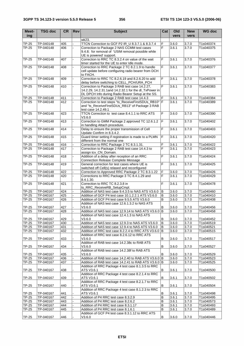
ETSI
ETSI TS 134 123-3 V5.5.0 (2006-06) 3563GPP TS 34.123-3 version 5.5.0 Release 5
Meet-ing
TSG doc CR Rev Subject Cat Old vers
New vers
WG doc
wk23. TP-25 TP-040148 405 - TTCN Correction to GCF P2 IR_U 8.3.7.1 & 8.3.7.4 F 3.6.0 3.7.0 T1s040374 TP-25 TP-040148 406 - Correction to Package 2 NAS CCMM test cases
9.4.8; for removal of 'USIM removal possible while UE is powered' support.
F 3.6.1 3.7.0 T1s040375
TP-25 TP-040148 407 - Correction to RRC TC 8.3.2.4 on value of the wait timer started for the UE to enter Idle mode.
F 3.6.1 3.7.0 T1s040376
TP-25 TP-040148 408 - Correction to RRC Package 2 TC 8.2.1.9 to handle cell update before configuring radio bearer from DCH to FACH.
F 3.6.1 3.7.0 T1s040377
TP-25 TP-040148 409 - Correction to RRC TC 8.2.6.19 and 8.2.6.20 to add delay before switching to CELL_PCH/URA_PCH
F 3.6.1 3.7.0 T1s040378
TP-25 TP-040148 410 - Correction to Package 3 RAB test case 14.2.27, 14.2.29, 14.2.31.1and 14.2.32.1 for the dl_TxPower in DL DPCH Info during Radio Bearer Setup at the SS.
F 3.6.1 3.7.0 T1s040383
TP-25 TP-040148 411 - Correction to Package 2 RAB test case 14.4.3 F 3.6.1 3.7.0 T1s040384 TP-25 TP-040148 412 - Correction to test steps "ts_ReceiveFirstSDUs_RB10"
and "ts_ReceiveFirstSDUs_RB13" of Package 3 RAB test case 14.2.49.1
F 3.6.1 3.7.0 T1s040389
TP-25 TP-040148 423 - TTCN Correction to test case 8.4.1.1 to RRC ATS V3.6.0
F 3.6.0 3.7.0 T1s040390
TP-25 TP-040148 413 - Correction to GMM Package 2 approved TC 12.6.1.2 in handling Attach procedure.
F 3.6.1 3.7.0 T1s040402
TP-25 TP-040148 414 - Delay to ensure the proper transmission of Cell Update Confirm in 8.3.4.2.
F 3.6.1 3.7.0 T1s040403
TP-25 TP-040148 415 - Guard timer setting if registration is made to a PLMN different from the normal one
F 3.6.1 3.7.0 T1s040420
TP-25 TP-040148 416 - Correction to RRC Package 2 TC 8.3.1.31. F 3.6.1 3.7.0 T1s040422 TP-25 TP-040148 417 - Correction to Package 2 RAB test case 14.4.3 to
assign tcv_CN_Domain. F 3.6.1 3.7.0 T1s040423
TP-25 TP-040148 418 - Addition of a delay after reception of an RRC Connection Release Complete Message
F 3.6.1 3.7.0 T1s040424
TP-25 TP-040148 419 - General correction for test cases where UE is switched off Cell(s) relased and reconfigured
F 3.6.1 3.7.0 T1s040425
TP-25 TP-040148 422 - Correction to Approved RRC Package 2 TC 8.3.1.22 F 3.6.0 3.7.0 T1s040426 TP-25 TP-040148 420 - Corrections to RRC Package 3 TC 8.4.1.29 and
8.4.1.30. F 3.6.1 3.7.0 T1s040429
TP-25 TP-040148 421 - Correction to RRC TC 8.2.3.8 in ts_RRC_ReceiveRB_SetupCmpl.
F 3.6.1 3.7.0 T1s040478
TP-25 TP-040167 424 - Addition of NAS test case 9.4.3.5 to NAS ATS V3.6.0 B 3.6.0 3.7.0 T1s040460 TP-25 TP-040167 425 - Addition of GCF P4 test case 10.1.2.2.1 ATS V3.6.0 B 3.6.0 3.7.0 T1s040410 TP-25 TP-040167 426 - Addition of GCF P4 test case 9.5.5 ATS V3.6.0 B 3.6.0 3.7.0 T1s040408
TP-25 TP-040167 427 - Addition of NAS test case 12.6.1.3.2 to NAS ATS V3.6.0 B 3.6.0 3.7.0 T1s040456
TP-25 TP-040167 428 - Addition of NAS test case 12.9.14 to NAS ATS V3.6.0 B 3.6.0 3.7.0 T1s040458
TP-25 TP-040167 429 - Addition of NAS test case 12.4.1.3 to NAS ATS V3.6.0 B 3.6.0 3.7.0 T1s040452
TP-25 TP-040167 430 - Addition of NAS test case 12.9.3 to NAS ATS V3.6.0 B 3.6.0 3.7.0 T1s040519 TP-25 TP-040167 431 - Addition of NAS test case 12.9.4 to NAS ATS V3.6.0 B 3.6.0 3.7.0 T1s040521 TP-25 TP-040167 432 - Addition of RRC test case 8.2.2.4 to RRC ATS V3.6.0 B 3.6.0 3.7.0 T1s040515
TP-25 TP-040167 433 - Addition of RRC test case 8.2.6.12 to RRC ATS V3.6.0 B 3.6.0 3.7.0 T1s040517
TP-25 TP-040167 434 - Addition of RAB test case 14.2.38c to RAB ATS V3.6.0 B 3.6.0 3.7.0 T1s040527
TP-25 TP-040167 435 - Addition of RAB test case 14.2.38f to RAB ATS V3.6.0 B 3.6.0 3.7.0 T1s040529
TP-25 TP-040167 436 - Addition of RAB test case 14.2.40 to RAB ATS V3.6.0 B 3.6.0 3.7.0 T1s040523 TP-25 TP-040167 437 - Addition of RAB test case 14.2.41 to RAB ATS V3.6.0 B 3.6.0 3.7.0 T1s040525
TP-25 TP-040167 438 - Addition of RRC Package 4 test case 8.1.3.5 to RRC ATS V3.6.1 B 3.6.1 3.7.0 T1s040500
TP-25 TP-040167 439 - Addition of RRC Package 4 test case 8.2.1.4 to RRC ATS V3.6.1 B 3.6.1 3.7.0 T1s040502
TP-25 TP-040167 440 - Addition of RRC Package 4 test case 8.2.1.7 to RRC ATS V3.6.1 B 3.6.1 3.7.0 T1s040504
TP-25 TP-040167 441 - Addition of RRC Package 4 test case 8.1.2.3 to RRC ATS V3.6.1 B 3.6.1 3.7.0 T1s040498
TP-25 TP-040167 442 - Addition of P4 RRC test case 8.3.2.9 B 3.6.1 3.7.0 T1s040495 TP-25 TP-040167 443 - Addition of P4 RRC test case 8.2.6.2 B 3.6.1 3.7.0 T1s040573 TP-25 TP-040167 444 - Addition of P4 RRC test case 8.3.1.17 B 3.6.1 3.7.0 T1s040493 TP-25 TP-040167 445 - Addition of P4 RRC test case 8.1.6.1 B 3.6.1 3.7.0 T1s040489
TP-25 TP-040167 446 - Addition of GCF P4 test case 8.3.1.12 to RRC ATS V3.6.0 B 3.6.0 3.7.0 T1s040446
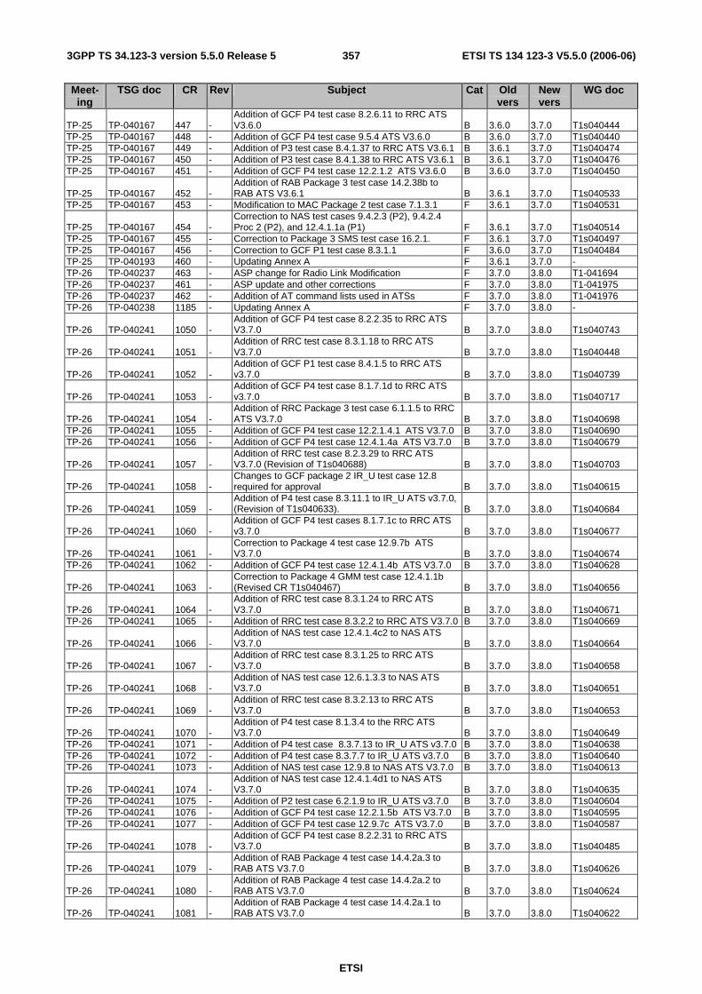
ETSI
ETSI TS 134 123-3 V5.5.0 (2006-06) 3573GPP TS 34.123-3 version 5.5.0 Release 5
Meet-ing
TSG doc CR Rev Subject Cat Old vers
New vers
WG doc
TP-25 TP-040167 447 - Addition of GCF P4 test case 8.2.6.11 to RRC ATS V3.6.0 B 3.6.0 3.7.0 T1s040444
TP-25 TP-040167 448 - Addition of GCF P4 test case 9.5.4 ATS V3.6.0 B 3.6.0 3.7.0 T1s040440 TP-25 TP-040167 449 - Addition of P3 test case 8.4.1.37 to RRC ATS V3.6.1 B 3.6.1 3.7.0 T1s040474 TP-25 TP-040167 450 - Addition of P3 test case 8.4.1.38 to RRC ATS V3.6.1 B 3.6.1 3.7.0 T1s040476 TP-25 TP-040167 451 - Addition of GCF P4 test case 12.2.1.2 ATS V3.6.0 B 3.6.0 3.7.0 T1s040450
TP-25 TP-040167 452 - Addition of RAB Package 3 test case 14.2.38b to RAB ATS V3.6.1 B 3.6.1 3.7.0 T1s040533
TP-25 TP-040167 453 - Modification to MAC Package 2 test case 7.1.3.1 F 3.6.1 3.7.0 T1s040531
TP-25 TP-040167 454 - Correction to NAS test cases 9.4.2.3 (P2), 9.4.2.4 Proc 2 (P2), and 12.4.1.1a (P1) F 3.6.1 3.7.0 T1s040514
TP-25 TP-040167 455 - Correction to Package 3 SMS test case 16.2.1. F 3.6.1 3.7.0 T1s040497 TP-25 TP-040167 456 - Correction to GCF P1 test case 8.3.1.1 F 3.6.0 3.7.0 T1s040484 TP-25 TP-040193 460 - Updating Annex A F 3.6.1 3.7.0 - TP-26 TP-040237 463 - ASP change for Radio Link Modification F 3.7.0 3.8.0 T1-041694 TP-26 TP-040237 461 - ASP update and other corrections F 3.7.0 3.8.0 T1-041975 TP-26 TP-040237 462 - Addition of AT command lists used in ATSs F 3.7.0 3.8.0 T1-041976 TP-26 TP-040238 1185 - Updating Annex A F 3.7.0 3.8.0 -
TP-26 TP-040241 1050 - Addition of GCF P4 test case 8.2.2.35 to RRC ATS V3.7.0 B 3.7.0 3.8.0 T1s040743
TP-26 TP-040241 1051 - Addition of RRC test case 8.3.1.18 to RRC ATS V3.7.0 B 3.7.0 3.8.0 T1s040448
TP-26 TP-040241 1052 - Addition of GCF P1 test case 8.4.1.5 to RRC ATS v3.7.0 B 3.7.0 3.8.0 T1s040739
TP-26 TP-040241 1053 - Addition of GCF P4 test case 8.1.7.1d to RRC ATS v3.7.0 B 3.7.0 3.8.0 T1s040717
TP-26 TP-040241 1054 - Addition of RRC Package 3 test case 6.1.1.5 to RRC ATS V3.7.0 B 3.7.0 3.8.0 T1s040698
TP-26 TP-040241 1055 - Addition of GCF P4 test case 12.2.1.4.1 ATS V3.7.0 B 3.7.0 3.8.0 T1s040690 TP-26 TP-040241 1056 - Addition of GCF P4 test case 12.4.1.4a ATS V3.7.0 B 3.7.0 3.8.0 T1s040679
TP-26 TP-040241 1057 - Addition of RRC test case 8.2.3.29 to RRC ATS V3.7.0 (Revision of T1s040688) B 3.7.0 3.8.0 T1s040703
TP-26 TP-040241 1058 - Changes to GCF package 2 IR_U test case 12.8 required for approval B 3.7.0 3.8.0 T1s040615
TP-26 TP-040241 1059 - Addition of P4 test case 8.3.11.1 to IR_U ATS v3.7.0, (Revision of T1s040633). B 3.7.0 3.8.0 T1s040684
TP-26 TP-040241 1060 - Addition of GCF P4 test cases 8.1.7.1c to RRC ATS v3.7.0 B 3.7.0 3.8.0 T1s040677
TP-26 TP-040241 1061 - Correction to Package 4 test case 12.9.7b ATS V3.7.0 B 3.7.0 3.8.0 T1s040674
TP-26 TP-040241 1062 - Addition of GCF P4 test case 12.4.1.4b ATS V3.7.0 B 3.7.0 3.8.0 T1s040628
TP-26 TP-040241 1063 - Correction to Package 4 GMM test case 12.4.1.1b (Revised CR T1s040467) B 3.7.0 3.8.0 T1s040656
TP-26 TP-040241 1064 - Addition of RRC test case 8.3.1.24 to RRC ATS V3.7.0 B 3.7.0 3.8.0 T1s040671
TP-26 TP-040241 1065 - Addition of RRC test case 8.3.2.2 to RRC ATS V3.7.0 B 3.7.0 3.8.0 T1s040669
TP-26 TP-040241 1066 - Addition of NAS test case 12.4.1.4c2 to NAS ATS V3.7.0 B 3.7.0 3.8.0 T1s040664
TP-26 TP-040241 1067 - Addition of RRC test case 8.3.1.25 to RRC ATS V3.7.0 B 3.7.0 3.8.0 T1s040658
TP-26 TP-040241 1068 - Addition of NAS test case 12.6.1.3.3 to NAS ATS V3.7.0 B 3.7.0 3.8.0 T1s040651
TP-26 TP-040241 1069 - Addition of RRC test case 8.3.2.13 to RRC ATS V3.7.0 B 3.7.0 3.8.0 T1s040653
TP-26 TP-040241 1070 - Addition of P4 test case 8.1.3.4 to the RRC ATS V3.7.0 B 3.7.0 3.8.0 T1s040649
TP-26 TP-040241 1071 - Addition of P4 test case 8.3.7.13 to IR_U ATS v3.7.0 B 3.7.0 3.8.0 T1s040638 TP-26 TP-040241 1072 - Addition of P4 test case 8.3.7.7 to IR_U ATS v3.7.0 B 3.7.0 3.8.0 T1s040640 TP-26 TP-040241 1073 - Addition of NAS test case 12.9.8 to NAS ATS V3.7.0 B 3.7.0 3.8.0 T1s040613
TP-26 TP-040241 1074 - Addition of NAS test case 12.4.1.4d1 to NAS ATS V3.7.0 B 3.7.0 3.8.0 T1s040635
TP-26 TP-040241 1075 - Addition of P2 test case 6.2.1.9 to IR_U ATS v3.7.0 B 3.7.0 3.8.0 T1s040604 TP-26 TP-040241 1076 - Addition of GCF P4 test case 12.2.1.5b ATS V3.7.0 B 3.7.0 3.8.0 T1s040595 TP-26 TP-040241 1077 - Addition of GCF P4 test case 12.9.7c ATS V3.7.0 B 3.7.0 3.8.0 T1s040587
TP-26 TP-040241 1078 - Addition of GCF P4 test case 8.2.2.31 to RRC ATS V3.7.0 B 3.7.0 3.8.0 T1s040485
TP-26 TP-040241 1079 - Addition of RAB Package 4 test case 14.4.2a.3 to RAB ATS V3.7.0 B 3.7.0 3.8.0 T1s040626
TP-26 TP-040241 1080 - Addition of RAB Package 4 test case 14.4.2a.2 to RAB ATS V3.7.0 B 3.7.0 3.8.0 T1s040624
TP-26 TP-040241 1081 - Addition of RAB Package 4 test case 14.4.2a.1 to RAB ATS V3.7.0 B 3.7.0 3.8.0 T1s040622

ETSI
ETSI TS 134 123-3 V5.5.0 (2006-06) 3583GPP TS 34.123-3 version 5.5.0 Release 5
Meet-ing
TSG doc CR Rev Subject Cat Old vers
New vers
WG doc
TP-26 TP-040241 1082 - Addition of RRC Package 4 test case 8.2.3.11 to RRC ATS V3.7.0 B 3.7.0 3.8.0 T1s040620
TP-26 TP-040241 1083 - Addition of NAS test case 12.4.3.4 to NAS ATS V3.7.0 B 3.7.0 3.8.0 T1s040609
TP-26 TP-040241 1084 - Addition of NAS test case 12.9.6 to NAS ATS V3.7.0 B 3.7.0 3.8.0 T1s040607
TP-26 TP-040241 1085 - Changes to GCF package 4 IR_U test case 8.3.7.9 required for approval. B 3.7.0 3.8.0 T1s040552
TP-26 TP-040241 1086 - Changes to GCF package 4 IR_U test case 8.3.7.5 required for approval. B 3.7.0 3.8.0 T1s040548
TP-26 TP-040241 1087 - Addition of GCF P4 test case 12.4.1.2 ATS V3.6.0 B 3.7.0 3.8.0 T1s040585 TP-26 TP-040241 1088 - Addition of GCF P4 test case 10.1.2.2.3 ATS V3.6.0 B 3.7.0 3.8.0 T1s040412 TP-26 TP-040241 1089 - Addition of GCF P4 test case 9.5.7.1 ATS V3.6.0 B 3.7.0 3.8.0 T1s040404
TP-26 TP-040241 1090 - Addition of GCF P4 test cases 8.1.12 to RRC ATS v3.6.1 B 3.7.0 3.8.0 T1s040602
TP-26 TP-040241 1091 - Addition of GCF P4 test cases 8.1.7.1b to RRC ATS v3.6.1 B 3.7.0 3.8.0 T1s040600
TP-26 TP-040241 1092 - Addition of GCF P4 test case 12.2.1.6.2 ATS V3.6.0 B 3.7.0 3.8.0 T1s040436 TP-26 TP-040241 1093 - Addition of GCF P4 test case 12.2.1.5a.1 ATS V3.6.0 B 3.7.0 3.8.0 T1s040434
TP-26 TP-040241 1094 - Addition of GCF P4 test case 8.3.1.15 to RRC ATS V3.6.0 B 3.7.0 3.8.0 T1s040487
TP-26 TP-040241 1095 - Addition of GCF P4 test case 8.1.2.4 ATS V3.6.0 B 3.7.0 3.8.0 T1s040442
TP-26 TP-040241 1096 - Addition of NAS test case 12.4.1.4d2 to NAS ATS V3.6.0 B 3.7.0 3.8.0 T1s040579
TP-26 TP-040241 1097 - Addition of GCF P3 test case 6.1.1.7 ATS V3.6.0 B 3.7.0 3.8.0 T1s040427 TP-26 TP-040241 1098 - Addition of GCF P3 test case 12.4.2.5a.1 ATS V3.6.0 B 3.7.0 3.8.0 T1s040472
TP-26 TP-040241 1099 - Re-submission of GCF package 2 IR_U test case 6.2.2.1 for approval. B 3.7.0 3.8.0 T1s040534
TP-26 TP-040241 1100 - Addition of RAB test case 14.2.51b.1 to RAB ATS V3.6.0 B 3.7.0 3.8.0 T1s040570
TP-26 TP-040241 1101 - Addition of RRC test case 10.1.2.3.7 to RRC ATS V3.6.1 B 3.7.0 3.8.0 T1s040508
TP-26 TP-040241 1102 - Addition of RRC test case 10.1.2.7.1 to RRC ATS V3.6.1 B 3.7.0 3.8.0 T1s040510
TP-26 TP-040241 1103 - Addition of RRC test case 10.1.2.3.2 to RRC ATS V3.6.1 B 3.7.0 3.8.0 T1s040506
TP-26 TP-040241 1104 - Addition of NAS Package 4 test case 12.2.1.6 Proc1 to NAS ATS V3.6.1 B 3.7.0 3.8.0 T1s040565
TP-26 TP-040241 1105 - Addition of NAS Package 4 test case 12.2.1.4 proc2 to NAS ATS V3.6.1 B 3.7.0 3.8.0 T1s040561
TP-26 TP-040241 1106 - Addition of NAS Package 4 test case 12.2.1.5a Proc2 to NAS ATS V3.6.1 B 3.7.0 3.8.0 T1s040563
TP-26 TP-040241 1107 - Addition of NAS Package 4 test case 12.2.1.10 to NAS ATS V3.6.1 B 3.7.0 3.8.0 T1s040559
TP-26 TP-040241 1108 - Addition of RAB test case 14.2.23a2 to RAB ATS V3.6.0 B 3.7.0 3.8.0 T1s040556
TP-26 TP-040241 1109 - Addition of NAS test case 12.6.1.3.1 to NAS ATS V3.6.0 B 3.7.0 3.8.0 T1s040454
TP-26 TP-040241 1110 - Addition of GCF P2 RRC 8.4.1.7 - Revision of T1s040381 B 3.7.0 3.8.0 T1s040766
TP-26 TP-040242 1111 - Correction to RRC P3 TC 8.4.1.37 F 3.7.0 3.8.0 T1s040735 TP-26 TP-040242 1112 - Correction to RRC P2 TC 8.3.1.31 for the timer value
before step 5. F 3.7.0 3.8.0 T1s040736
TP-26 TP-040242 1113 - Correction to approved GCF P4 test cases 8.1.7.1c F 3.7.0 3.8.0 T1s040734 TP-26 TP-040242 1114 - Correction to approved package 4 NAS Test case
tc_12_6_1_3_2 F 3.7.0 3.8.0 T1s040737
TP-26 TP-040242 1115 - Corrections to RRC Package 1 TC 8.4.1.1. F 3.7.0 3.8.0 T1s040738 TP-26 TP-040242 1116 - Correction to the RRC default message handler on
Dc SAP for Deactivate PDP Context Request message in RRC ATS.
F 3.7.0 3.8.0 T1s040731
TP-26 TP-040242 1117 - Correction to TTCN for MultiRAB test cases. F 3.7.0 3.8.0 T1s040732 TP-26 TP-040242 1118 - Correction to approved package 4 NAS Test case
tc_12_6_1_3_1 F 3.7.0 3.8.0 T1s040733
TP-26 TP-040242 1119 - Summary of regression errors in the wk45 ATS. F 3.7.0 3.8.0 T1s040723 TP-26 TP-040242 1120 - Correction to RRC P4 TC 8.1.7.1b for comments in
test steps. F 3.7.0 3.8.0 T1s040711
TP-26 TP-040242 1121 - Correction to GCF P3 NAS test Cases 13.2.1.1, 13.2.2.1 and 13.2.2.2
F 3.7.0 3.8.0 T1s040712
TP-26 TP-040242 1122 - Correction to GCF P4 NAS test Case 12.2.1.6.2 F 3.7.0 3.8.0 T1s040713 TP-26 TP-040242 1123 - Correction to RAB test case 14.4.2.3 and 14.4.2a.3. F 3.7.0 3.8.0 T1s040714 TP-26 TP-040242 1124 - Correction to RRC Package 2 TC 8.3.1.3. F 3.7.0 3.8.0 T1s040722 TP-26 TP-040242 1125 - Correction to AT Command used for GCF P1 NAS
test Case 10.1.2.5.1 F 3.7.0 3.8.0 T1s040724
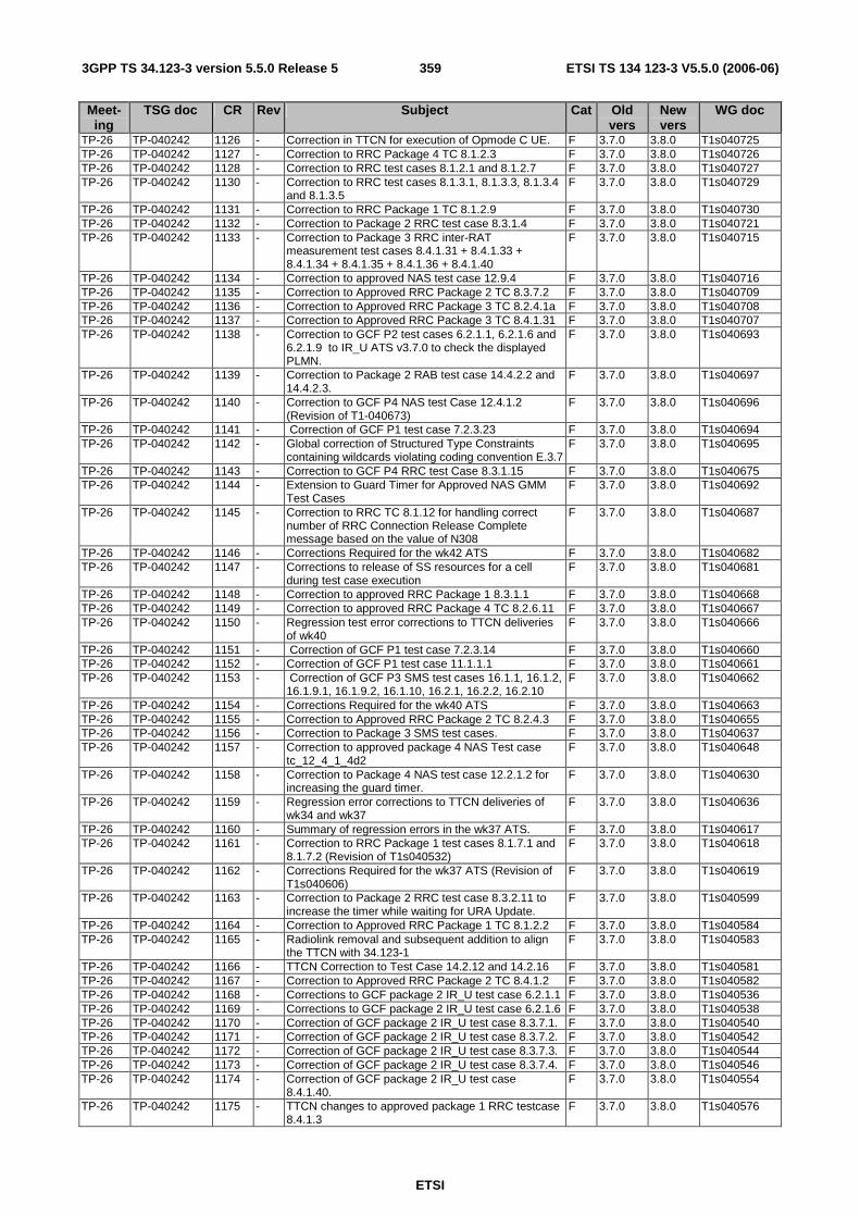
ETSI
ETSI TS 134 123-3 V5.5.0 (2006-06) 3593GPP TS 34.123-3 version 5.5.0 Release 5
Meet-ing
TSG doc CR Rev Subject Cat Old vers
New vers
WG doc
TP-26 TP-040242 1126 - Correction in TTCN for execution of Opmode C UE. F 3.7.0 3.8.0 T1s040725 TP-26 TP-040242 1127 - Correction to RRC Package 4 TC 8.1.2.3 F 3.7.0 3.8.0 T1s040726 TP-26 TP-040242 1128 - Correction to RRC test cases 8.1.2.1 and 8.1.2.7 F 3.7.0 3.8.0 T1s040727 TP-26 TP-040242 1130 - Correction to RRC test cases 8.1.3.1, 8.1.3.3, 8.1.3.4
and 8.1.3.5 F 3.7.0 3.8.0 T1s040729
TP-26 TP-040242 1131 - Correction to RRC Package 1 TC 8.1.2.9 F 3.7.0 3.8.0 T1s040730 TP-26 TP-040242 1132 - Correction to Package 2 RRC test case 8.3.1.4 F 3.7.0 3.8.0 T1s040721 TP-26 TP-040242 1133 - Correction to Package 3 RRC inter-RAT
measurement test cases 8.4.1.31 + 8.4.1.33 + 8.4.1.34 + 8.4.1.35 + 8.4.1.36 + 8.4.1.40
F 3.7.0 3.8.0 T1s040715
TP-26 TP-040242 1134 - Correction to approved NAS test case 12.9.4 F 3.7.0 3.8.0 T1s040716 TP-26 TP-040242 1135 - Correction to Approved RRC Package 2 TC 8.3.7.2 F 3.7.0 3.8.0 T1s040709 TP-26 TP-040242 1136 - Correction to Approved RRC Package 3 TC 8.2.4.1a F 3.7.0 3.8.0 T1s040708 TP-26 TP-040242 1137 - Correction to Approved RRC Package 3 TC 8.4.1.31 F 3.7.0 3.8.0 T1s040707 TP-26 TP-040242 1138 - Correction to GCF P2 test cases 6.2.1.1, 6.2.1.6 and
6.2.1.9 to IR_U ATS v3.7.0 to check the displayed PLMN.
F 3.7.0 3.8.0 T1s040693
TP-26 TP-040242 1139 - Correction to Package 2 RAB test case 14.4.2.2 and 14.4.2.3.
F 3.7.0 3.8.0 T1s040697
TP-26 TP-040242 1140 - Correction to GCF P4 NAS test Case 12.4.1.2 (Revision of T1-040673)
F 3.7.0 3.8.0 T1s040696
TP-26 TP-040242 1141 - Correction of GCF P1 test case 7.2.3.23 F 3.7.0 3.8.0 T1s040694 TP-26 TP-040242 1142 - Global correction of Structured Type Constraints
containing wildcards violating coding convention E.3.7 F 3.7.0 3.8.0 T1s040695
TP-26 TP-040242 1143 - Correction to GCF P4 RRC test Case 8.3.1.15 F 3.7.0 3.8.0 T1s040675 TP-26 TP-040242 1144 - Extension to Guard Timer for Approved NAS GMM
Test Cases F 3.7.0 3.8.0 T1s040692
TP-26 TP-040242 1145 - Correction to RRC TC 8.1.12 for handling correct number of RRC Connection Release Complete message based on the value of N308
F 3.7.0 3.8.0 T1s040687
TP-26 TP-040242 1146 - Corrections Required for the wk42 ATS F 3.7.0 3.8.0 T1s040682 TP-26 TP-040242 1147 - Corrections to release of SS resources for a cell
during test case execution F 3.7.0 3.8.0 T1s040681
TP-26 TP-040242 1148 - Correction to approved RRC Package 1 8.3.1.1 F 3.7.0 3.8.0 T1s040668 TP-26 TP-040242 1149 - Correction to approved RRC Package 4 TC 8.2.6.11 F 3.7.0 3.8.0 T1s040667 TP-26 TP-040242 1150 - Regression test error corrections to TTCN deliveries
of wk40 F 3.7.0 3.8.0 T1s040666
TP-26 TP-040242 1151 - Correction of GCF P1 test case 7.2.3.14 F 3.7.0 3.8.0 T1s040660 TP-26 TP-040242 1152 - Correction of GCF P1 test case 11.1.1.1 F 3.7.0 3.8.0 T1s040661 TP-26 TP-040242 1153 - Correction of GCF P3 SMS test cases 16.1.1, 16.1.2,
16.1.9.1, 16.1.9.2, 16.1.10, 16.2.1, 16.2.2, 16.2.10 F 3.7.0 3.8.0 T1s040662
TP-26 TP-040242 1154 - Corrections Required for the wk40 ATS F 3.7.0 3.8.0 T1s040663 TP-26 TP-040242 1155 - Correction to Approved RRC Package 2 TC 8.2.4.3 F 3.7.0 3.8.0 T1s040655 TP-26 TP-040242 1156 - Correction to Package 3 SMS test cases. F 3.7.0 3.8.0 T1s040637 TP-26 TP-040242 1157 - Correction to approved package 4 NAS Test case
tc_12_4_1_4d2 F 3.7.0 3.8.0 T1s040648
TP-26 TP-040242 1158 - Correction to Package 4 NAS test case 12.2.1.2 for increasing the guard timer.
F 3.7.0 3.8.0 T1s040630
TP-26 TP-040242 1159 - Regression error corrections to TTCN deliveries of wk34 and wk37
F 3.7.0 3.8.0 T1s040636
TP-26 TP-040242 1160 - Summary of regression errors in the wk37 ATS. F 3.7.0 3.8.0 T1s040617 TP-26 TP-040242 1161 - Correction to RRC Package 1 test cases 8.1.7.1 and
8.1.7.2 (Revision of T1s040532) F 3.7.0 3.8.0 T1s040618
TP-26 TP-040242 1162 - Corrections Required for the wk37 ATS (Revision of T1s040606)
F 3.7.0 3.8.0 T1s040619
TP-26 TP-040242 1163 - Correction to Package 2 RRC test case 8.3.2.11 to increase the timer while waiting for URA Update.
F 3.7.0 3.8.0 T1s040599
TP-26 TP-040242 1164 - Correction to Approved RRC Package 1 TC 8.1.2.2 F 3.7.0 3.8.0 T1s040584 TP-26 TP-040242 1165 - Radiolink removal and subsequent addition to align
the TTCN with 34.123-1 F 3.7.0 3.8.0 T1s040583
TP-26 TP-040242 1166 - TTCN Correction to Test Case 14.2.12 and 14.2.16 F 3.7.0 3.8.0 T1s040581 TP-26 TP-040242 1167 - Correction to Approved RRC Package 2 TC 8.4.1.2 F 3.7.0 3.8.0 T1s040582 TP-26 TP-040242 1168 - Corrections to GCF package 2 IR_U test case 6.2.1.1 F 3.7.0 3.8.0 T1s040536 TP-26 TP-040242 1169 - Corrections to GCF package 2 IR_U test case 6.2.1.6 F 3.7.0 3.8.0 T1s040538 TP-26 TP-040242 1170 - Correction of GCF package 2 IR_U test case 8.3.7.1. F 3.7.0 3.8.0 T1s040540 TP-26 TP-040242 1171 - Correction of GCF package 2 IR_U test case 8.3.7.2. F 3.7.0 3.8.0 T1s040542 TP-26 TP-040242 1172 - Correction of GCF package 2 IR_U test case 8.3.7.3. F 3.7.0 3.8.0 T1s040544 TP-26 TP-040242 1173 - Correction of GCF package 2 IR_U test case 8.3.7.4. F 3.7.0 3.8.0 T1s040546 TP-26 TP-040242 1174 - Correction of GCF package 2 IR_U test case
8.4.1.40. F 3.7.0 3.8.0 T1s040554
TP-26 TP-040242 1175 - TTCN changes to approved package 1 RRC testcase 8.4.1.3
F 3.7.0 3.8.0 T1s040576
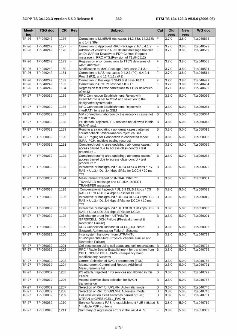
ETSI
ETSI TS 134 123-3 V5.5.0 (2006-06) 3603GPP TS 34.123-3 version 5.5.0 Release 5
Meet-ing
TSG doc CR Rev Subject Cat Old vers
New vers
WG doc
TP-26 TP-040242 1176 - Correction to MultiRAB test cases 14.2.38a, 14.2.38b and 14.2.38e
F 3.7.0 3.8.0 T1s040575
TP-26 TP-040242 1177 - Correction to Approved RRC Package 2 TC 8.4.1.2 F 3.7.0 3.8.0 T1s040572 TP-26 TP-040242 1178 - Addition of verdicts in RRC default message handler
on Dc SAP for Deactivate PDP Context Request message in RRC ATS.(Revision of T1s040512)
F 3.7.0 3.8.0 T1s040569
TP-26 TP-040242 1179 - Regression error corrections to TTCN deliveries of wk26 and wk31
F 3.7.0 3.8.0 T1s040558
TP-26 TP-040242 1180 - Modification to MAC Package 2 test case 7.1.3.1 F 3.7.0 3.8.0 T1s040531 TP-26 TP-040242 1181 - Correction to NAS test cases 9.4.2.3 (P2), 9.4.2.4
Proc 2 (P2), and 12.4.1.1a (P1) F 3.7.0 3.8.0 T1s040514
TP-26 TP-040242 1182 - Correction to Package 3 SMS test case 16.2.1. F 3.7.0 3.8.0 T1s040497 TP-26 TP-040242 1183 - Correction to GCF P1 test case 8.3.1.1 F 3.7.0 3.8.0 T1s040484 TP-26 TP-040242 1184 - Regression test error corrections to TTCN deliveries
of wk42 F 3.7.0 3.8.0 T1s040699
TP-27 TP-050039 1185 RRC Connection Establishment: Reject with InterRATInfo is set to GSM and selection to the designated system fails
B 3.8.0 5.0.0 T1s050056
TP-27 TP-050039 1186 RRC Connection Establishment: Reject with interRATInfo is set to GSM
B 3.8.0 5.0.0 T1s050054
TP-27 TP-050039 1187 MM connection / abortion by the network / cause not equal to #6
B 3.8.0 5.0.0 T1s050044
TP-27 TP-050039 1188 PS detach / rejected / PS services not allowed in this PLMN/ test1
B 3.8.0 5.0.0 T1s050046
TP-27 TP-050039 1189 Routing area updating / abnormal cases / attempt counter check / miscellaneous reject causes
B 3.8.0 5.0.0 T1s050018
TP-27 TP-050039 1190 RRC / Paging for Connection in connected mode (URA_PCH, multiple paging records)
B 3.8.0 5.0.0 T1s050038
TP-27 TP-050039 1191 Combined routing area updating / abnormal cases / access barred due to access class control / test procedure 1
B 3.8.0 5.0.0 T1s050036
TP-27 TP-050039 1192 Combined routing area updating / abnormal cases / access barred due to access class control / test procedure 2
B 3.8.0 5.0.0 T1s050034
TP-27 TP-050039 1193 Interactive or background / UL:64 DL:384 kbps / PS RAB + UL:3.4 DL: 3.4 kbps SRBs for DCCH / 20 ms TTI
B 3.8.0 5.0.0 T1s050025
TP-27 TP-050039 1194 Measurement Report on INITIAL DIRECT TRANSFER message and UPLINK DIRECT TRANSFER message
B 3.8.0 5.0.0 T1s050031
TP-27 TP-050039 1195 Conversational / speech / UL:5.9 DL:5.9 kbps / CS RAB + UL:3.4 DL:3.4 kbps SRBs for DCCH
B 3.8.0 5.0.0 T1s050023
TP-27 TP-050039 1196 Interactive or background / UL:384 DL:384 kbps / PS RAB + UL:3.4 DL:3.4 kbps SRBs for DCCH / 10 ms TTI
B 3.8.0 5.0.0 T1s050010
TP-27 TP-050039 1197 Interactive or background / UL:128 DL:128 kbps / PS RAB + UL:3.4 DL:3.4 kbps SRBs for DCCH
B 3.8.0 5.0.0 T1s050008
TP-27 TP-050039 1198 Cell change order from UTRAN/To GPRS/CELL_DCH/Failure (Physical channel & Reversion Failure)
B 3.8.0 5.0.0 T1s050001
TP-27 TP-050039 1199 RRC Connection Release in CELL_DCH state (Network Authentication Failure): Success
B 3.8.0 5.0.0 T1s050006
TP-27 TP-050039 1200 Inter system handover from UTRAN/To GSM/Speech/Failure (Physical channel Failure and Reversion Failure)
B 3.8.0 5.0.0 T1s040798
TP-27 TP-050039 1201 Cell reselection using cell status and cell reservations B 3.8.0 5.0.0 T1s040794 TP-27 TP-050039 1202 RRC / Radio Bearer Establishment for transition from
CELL_DCH to CELL_FACH (Frequency band modification): Success
B 3.8.0 5.0.0 T1s040796
TP-27 TP-050039 1203 Correct Selection of RACH parameters (FDD) B 3.8.0 5.0.0 T1s040755 TP-27 TP-050039 1204 Measurement Control and Report: Additional
Measurements list B 3.8.0 5.0.0 T1s040791
TP-27 TP-050039 1205 PS attach / rejected / PS services not allowed in this PLMN
B 3.8.0 5.0.0 T1s040779
TP-27 TP-050039 1206 Access Service class selection for RACH transmission
B 3.8.0 5.0.0 T1s040757
TP-27 TP-050039 1207 Selection of RAT for UPLMN; Automatic mode B 3.8.0 5.0.0 T1s040746 TP-27 TP-050039 1208 Selection of RAT for OPLMN; Automatic mode B 3.8.0 5.0.0 T1s040748 TP-27 TP-050039 1209 Cell reselection if cell becomes barred or S<0;
UTRAN to GPRS (CELL_FACH) B 3.8.0 5.0.0 T1s040701
TP-27 TP-050039 1210 Service Request / RAB re-establishment / UE initiated / multiple PDP contexts
B 3.8.0 5.0.0 T1s040719
TP-27 TP-050040 1211 Summary of regression errors in the wk04 ATS F 3.8.0 5.0.0 T1s050063
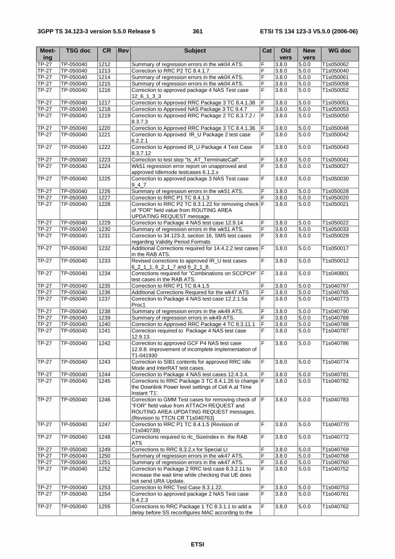
ETSI
ETSI TS 134 123-3 V5.5.0 (2006-06) 3613GPP TS 34.123-3 version 5.5.0 Release 5
Meet-ing
TSG doc CR Rev Subject Cat Old vers
New vers
WG doc
TP-27 TP-050040 1212 Summary of regression errors in the wk04 ATS. F 3.8.0 5.0.0 T1s050062 TP-27 TP-050040 1213 Correction to RRC P2 TC 8.4.1.7 F 3.8.0 5.0.0 T1s050040 TP-27 TP-050040 1214 Summary of regression errors in the wk04 ATS. F 3.8.0 5.0.0 T1s050061 TP-27 TP-050040 1215 Summary of regression errors in the wk04 ATS. F 3.8.0 5.0.0 T1s050058 TP-27 TP-050040 1216 Correction to approved package 4 NAS Test case
12_6_1_3_3 F 3.8.0 5.0.0 T1s050052
TP-27 TP-050040 1217 Correction to Approved RRC Package 3 TC 8.4.1.38 F 3.8.0 5.0.0 T1s050051 TP-27 TP-050040 1218 Correction to Approved NAS Package 3 TC 9.4.7 F 3.8.0 5.0.0 T1s050053 TP-27 TP-050040 1219 Correction to Approved RRC Package 2 TC 8.3.7.2 /
8.3.7.3 F 3.8.0 5.0.0 T1s050050
TP-27 TP-050040 1220 Correction to Approved RRC Package 3 TC 8.4.1.36 F 3.8.0 5.0.0 T1s050048 TP-27 TP-050040 1221 Correction to Approved IR_U Package 2 test case
6.2.2.1 F 3.8.0 5.0.0 T1s050042
TP-27 TP-050040 1222 Correction to Approved IR_U Package 4 Test Case 8.3.7.12
F 3.8.0 5.0.0 T1s050043
TP-27 TP-050040 1223 Correction to test step "ts_AT_TerminateCall". F 3.8.0 5.0.0 T1s050041 TP-27 TP-050040 1224 Wk51 regression error report on unapproved and
approved Idlemode testcases 6.1.2.x F 3.8.0 5.0.0 T1s050027
TP-27 TP-050040 1225 Correction to approved package 3 NAS Test case 9_4_7
F 3.8.0 5.0.0 T1s050030
TP-27 TP-050040 1226 Summary of regression errors in the wk51 ATS. F 3.8.0 5.0.0 T1s050028 TP-27 TP-050040 1227 Correction to RRC P1 TC 8.4.1.3 F 3.8.0 5.0.0 T1s050020 TP-27 TP-050040 1228 Correction to RRC P2 TC 8.3.1.22 for removing check
of "FOR" field value from ROUTING AREA UPDATING REQUEST message.
F 3.8.0 5.0.0 T1s050021
TP-27 TP-050040 1229 Correction to Package 4 NAS test case 12.9.14 F 3.8.0 5.0.0 T1s050022 TP-27 TP-050040 1230 Summary of regression errors in the wk51 ATS. F 3.8.0 5.0.0 T1s050033 TP-27 TP-050040 1231 Correction to 34.123-3, section 16, SMS test cases
regarding Validity Period Formats F 3.8.0 5.0.0 T1s050029
TP-27 TP-050040 1232 Additional Corrections required for 14.4.2.2 test cases in the RAB ATS.
F 3.8.0 5.0.0 T1s050017
TP-27 TP-050040 1233 Revised corrections to approved IR_U test cases 6_2_1_1, 6_2_1_7 and 6_2_1_8.
F 3.8.0 5.0.0 T1s050012
TP-27 TP-050040 1234 Corrections required for "Combinations on SCCPCH" test cases in the RAB ATS.
F 3.8.0 5.0.0 T1s040801
TP-27 TP-050040 1235 Correction to RRC P1 TC 8.4.1.5 F 3.8.0 5.0.0 T1s040797 TP-27 TP-050040 1236 Additional Corrections Required for the wk47 ATS F 3.8.0 5.0.0 T1s040765 TP-27 TP-050040 1237 Correction to Package 4 NAS test case 12.2.1.5a
Proc1 F 3.8.0 5.0.0 T1s040773
TP-27 TP-050040 1238 Summary of regression errors in the wk49 ATS. F 3.8.0 5.0.0 T1s040790 TP-27 TP-050040 1239 Summary of regression errors in wk49 ATS. F 3.8.0 5.0.0 T1s040789 TP-27 TP-050040 1240 Correction to Approved RRC Package 4 TC 8.3.11.1 F 3.8.0 5.0.0 T1s040788 TP-27 TP-050040 1241 Correction required to Package 4 NAS test case
12.9.13. F 3.8.0 5.0.0 T1s040787
TP-27 TP-050040 1242 Correction to approved GCF P4 NAS test case 12.9.8: improvement of incomplete implementation of T1-041930
F 3.8.0 5.0.0 T1s040786
TP-27 TP-050040 1243 Correction to SIB1 contents for approved RRC Idle Mode and InterRAT test cases.
F 3.8.0 5.0.0 T1s040774
TP-27 TP-050040 1244 Correction to Package 4 NAS test cases 12.4.3.4. F 3.8.0 5.0.0 T1s040781 TP-27 TP-050040 1245 Corrections to RRC Package 3 TC 8.4.1.26 to change
the Downlink Power level settings of Cell A at Time Instant 'T1'.
F 3.8.0 5.0.0 T1s040782
TP-27 TP-050040 1246 Correction to GMM Test cases for removing check of "FOR" field value from ATTACH REQUEST and ROUTING AREA UPDATING REQUEST messages. (Revision to TTCN CR T1s040763)
F 3.8.0 5.0.0 T1s040783
TP-27 TP-050040 1247 Correction to RRC P1 TC 8.4.1.5 (Revision of T1s040739)
F 3.8.0 5.0.0 T1s040770
TP-27 TP-050040 1248 Corrections required to rlc_SizeIndex in the RAB ATS
F 3.8.0 5.0.0 T1s040772
TP-27 TP-050040 1249 Corrections to RRC 8.3.2.x for Special LI F 3.8.0 5.0.0 T1s040769 TP-27 TP-050040 1250 Summary of regression errors in the wk47 ATS. F 3.8.0 5.0.0 T1s040768 TP-27 TP-050040 1251 Summary of regression errors in the wk47 ATS. F 3.8.0 5.0.0 T1s040760 TP-27 TP-050040 1252 Correction to Package 2 RRC test case 8.3.2.11 to
increase the wait time while checking that UE does not send URA Update.
F 3.8.0 5.0.0 T1s040752
TP-27 TP-050040 1253 Correction to RRC Test Case 8.3.1.22. F 3.8.0 5.0.0 T1s040753 TP-27 TP-050040 1254 Correction to approved package 2 NAS Test case
9.4.2.3 F 3.8.0 5.0.0 T1s040761
TP-27 TP-050040 1255 Corrections to RRC Package 1 TC 8.3.1.1 to add a delay before SS reconfigures MAC according to the
F 3.8.0 5.0.0 T1s040762
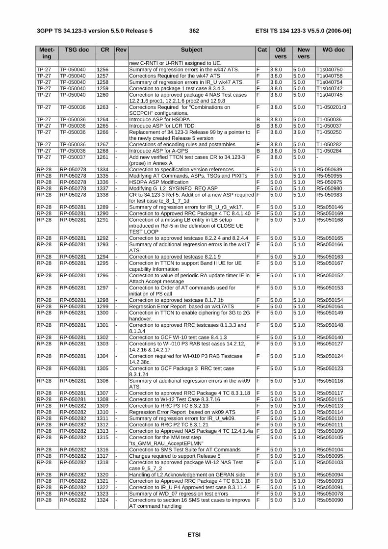
ETSI
ETSI TS 134 123-3 V5.5.0 (2006-06) 3623GPP TS 34.123-3 version 5.5.0 Release 5
Meet-ing
TSG doc CR Rev Subject Cat Old vers
New vers
WG doc
new C-RNTI or U-RNTI assigned to UE. TP-27 TP-050040 1256 Summary of regression errors in the wk47 ATS. F 3.8.0 5.0.0 T1s040750 TP-27 TP-050040 1257 Corrections Required for the wk47 ATS F 3.8.0 5.0.0 T1s040758 TP-27 TP-050040 1258 Summary of regression errors in IR_U wk47 ATS. F 3.8.0 5.0.0 T1s040754 TP-27 TP-050040 1259 Correction to package 1 test case 8.3.4.3. F 3.8.0 5.0.0 T1s040742 TP-27 TP-050040 1260 Correction to approved package 4 NAS Test cases
12.2.1.6 proc1, 12.2.1.6 proc2 and 12.9.8 F 3.8.0 5.0.0 T1s040745
TP-27 TP-050036 1263 - Corrections Required for "Combinations on SCCPCH" configurations.
F 3.8.0 5.0.0 T1-050201r3
TP-27 TP-050036 1264 - Introduce ASP for HSDPA B 3.8.0 5.0.0 T1-050036 TP-27 TP-050036 1265 - Introduce ASP for LCR TDD B 3.8.0 5.0.0 T1-050037 TP-27 TP-050036 1266 - Replacement of 34.123-3 Release 99 by a pointer to
the newly created Release 5 version F 3.8.0 3.9.0 T1-050250
TP-27 TP-050036 1267 - Corrections of encoding rules and postambles F 3.8.0 5.0.0 T1-050282 TP-27 TP-050036 1268 - Introduce ASP for A-GPS B 3.8.0 5.0.0 T1-050284 TP-27 TP-050037 1261 - Add new verified TTCN test cases CR to 34.123-3
(prose) in Annex A F 3.8.0 5.0.0 -
RP-28 RP-050278 1334 - Correction to specification version references F 5.0.0 5.1.0 R5-050639 RP-28 RP-050278 1335 - Modifying AT Commands, ASPs, TSOs and PIXITs F 5.0.0 5.1.0 R5-050955 RP-28 RP-050278 1336 - HSDPA ASP Modification F 5.0.0 5.1.0 R5-050975 RP-28 RP-050278 1337 - Modifying G_L2_SYSINFO_REQ ASP F 5.0.0 5.1.0 R5-050980 RP-28 RP-050278 1338 - CR to 34.123-3 Rel-5: Addition of a new ASP required
for test case tc_8_1_7_1d F 5.0.0 5.1.0 R5-050983
RP-28 RP-050281 1289 - Summary of regression errors for IR_U_r3_wk17. F 5.0.0 5.1.0 R5s050146 RP-28 RP-050281 1290 - Correction to Approved RRC Package 4 TC 8.4.1.40 F 5.0.0 5.1.0 R5s050169 RP-28 RP-050281 1291 - Correction of a missing LB entity in LB setup
introduced in Rel-5 in the definition of CLOSE UE TEST LOOP
F 5.0.0 5.1.0 R5s050168
RP-28 RP-050281 1292 - Correction to approved testcase 8.2.2.4 and 8.2.4.4 F 5.0.0 5.1.0 R5s050165 RP-28 RP-050281 1293 - Summary of additional regression errors in the wk17
ATS. F 5.0.0 5.1.0 R5s050166
RP-28 RP-050281 1294 - Correction to approved testcase 8.2.1.9 F 5.0.0 5.1.0 R5s050163 RP-28 RP-050281 1295 - Correction in TTCN to support Band II UE for UE
capability Information F 5.0.0 5.1.0 R5s050167
RP-28 RP-050281 1296 - Correction to value of periodic RA update timer IE in Attach Accept message
F 5.0.0 5.1.0 R5s050152
RP-28 RP-050281 1297 - Correction to Order of AT commands used for initiation of PS call
F 5.0.0 5.1.0 R5s050153
RP-28 RP-050281 1298 - Correction to approved testcase 8.1.7.1b F 5.0.0 5.1.0 R5s050154 RP-28 RP-050281 1299 - Regression Error Report based on wk17ATS F 5.0.0 5.1.0 R5s050164 RP-28 RP-050281 1300 - Correction in TTCN to enable ciphering for 3G to 2G
handover. F 5.0.0 5.1.0 R5s050149
RP-28 RP-050281 1301 - Correction to approved RRC testcases 8.1.3.3 and 8.1.3.4
F 5.0.0 5.1.0 R5s050148
RP-28 RP-050281 1302 - Correction to GCF WI-10 test case 8.4.1.3 F 5.0.0 5.1.0 R5s050140 RP-28 RP-050281 1303 - Corrections to WI-010 P3 RAB test cases 14.2.12,
14.2.16 & 14.2.17 F 5.0.0 5.1.0 R5s050127
RP-28 RP-050281 1304 - Correction required for WI-010 P3 RAB Testcase 14.2.38c.
F 5.0.0 5.1.0 R5s050124
RP-28 RP-050281 1305 - Correction to GCF Package 3 RRC test case 8.3.1.24
F 5.0.0 5.1.0 R5s050123
RP-28 RP-050281 1306 - Summary of additional regression errors in the wk09 ATS.
F 5.0.0 5.1.0 R5s050116
RP-28 RP-050281 1307 - Correction to approved RRC Package 4 TC 8.3.1.18 F 5.0.0 5.1.0 R5s050117 RP-28 RP-050281 1308 - Correction to WI-12 Test Case 8.3.7.16 F 5.0.0 5.1.0 R5s050115 RP-28 RP-050282 1309 - Correction to RRC P3 TC 8.3.2.13 F 5.0.0 5.1.0 R5s050113 RP-28 RP-050282 1310 - Regression Error Report based on wk09 ATS F 5.0.0 5.1.0 R5s050114 RP-28 RP-050282 1311 - Summary of regression errors for IR_U_wk09. F 5.0.0 5.1.0 R5s050110 RP-28 RP-050282 1312 - Correction to RRC P2 TC 8.3.1.21 F 5.0.0 5.1.0 R5s050111 RP-28 RP-050282 1313 - Correction to Approved NAS Package 4 TC 12.4.1.4a F 5.0.0 5.1.0 R5s050109 RP-28 RP-050282 1315 - Correction for the MM test step
"ts_GMM_RAU_AcceptEPLMN" F 5.0.0 5.1.0 R5s050105
RP-28 RP-050282 1316 - Correction to SMS Test Suite for AT Commands F 5.0.0 5.1.0 R5s050104 RP-28 RP-050282 1317 - Changes required to support Release 5 F 5.0.0 5.1.0 R5s050095 RP-28 RP-050282 1318 - Correction to approved package WI-12 NAS Test
case 9_5_7_2 F 5.0.0 5.1.0 R5s050103
RP-28 RP-050282 1320 - Handling of L2 Acknowledgement on GERAN side. F 5.0.0 5.1.0 R5s050094 RP-28 RP-050282 1321 - Correction to Approved RRC Package 4 TC 8.3.1.18 F 5.0.0 5.1.0 R5s050093 RP-28 RP-050282 1322 - Correction to IR_U P4 Approved test case 8.3.11.4 F 5.0.0 5.1.0 R5s050091 RP-28 RP-050282 1323 - Summary of iWD_07 regression test errors F 5.0.0 5.1.0 R5s050078 RP-28 RP-050282 1324 - Corrections to section 16 SMS test cases to improve
AT command handling F 5.0.0 5.1.0 R5s050090
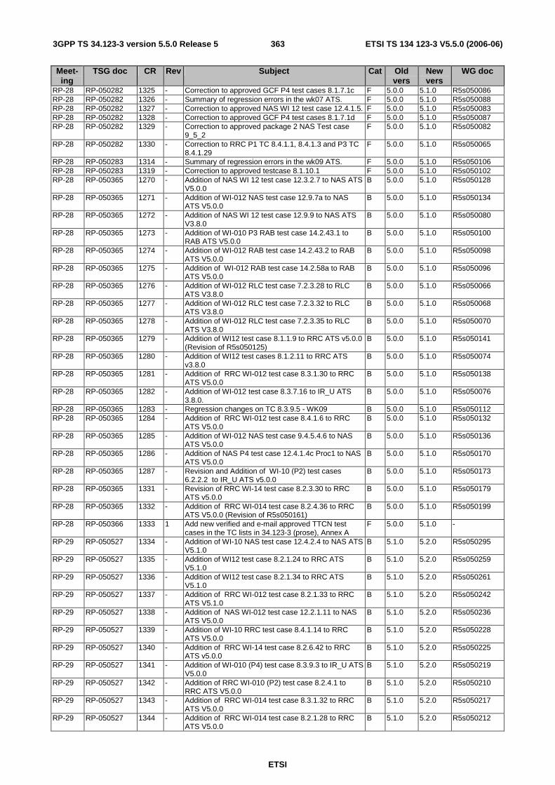
ETSI
ETSI TS 134 123-3 V5.5.0 (2006-06) 3633GPP TS 34.123-3 version 5.5.0 Release 5
Meet-ing
TSG doc CR Rev Subject Cat Old vers
New vers
WG doc
RP-28 RP-050282 1325 - Correction to approved GCF P4 test cases 8.1.7.1c F 5.0.0 5.1.0 R5s050086 RP-28 RP-050282 1326 - Summary of regression errors in the wk07 ATS. F 5.0.0 5.1.0 R5s050088 RP-28 RP-050282 1327 - Correction to approved NAS WI 12 test case 12.4.1.5. F 5.0.0 5.1.0 R5s050083 RP-28 RP-050282 1328 - Correction to approved GCF P4 test cases 8.1.7.1d F 5.0.0 5.1.0 R5s050087 RP-28 RP-050282 1329 - Correction to approved package 2 NAS Test case
9_5_2 F 5.0.0 5.1.0 R5s050082
RP-28 RP-050282 1330 - Correction to RRC P1 TC 8.4.1.1, 8.4.1.3 and P3 TC 8.4.1.29
F 5.0.0 5.1.0 R5s050065
RP-28 RP-050283 1314 - Summary of regression errors in the wk09 ATS. F 5.0.0 5.1.0 R5s050106 RP-28 RP-050283 1319 - Correction to approved testcase 8.1.10.1 F 5.0.0 5.1.0 R5s050102 RP-28 RP-050365 1270 - Addition of NAS WI 12 test case 12.3.2.7 to NAS ATS
V5.0.0 B 5.0.0 5.1.0 R5s050128
RP-28 RP-050365 1271 - Addition of WI-012 NAS test case 12.9.7a to NAS ATS V5.0.0
B 5.0.0 5.1.0 R5s050134
RP-28 RP-050365 1272 - Addition of NAS WI 12 test case 12.9.9 to NAS ATS V3.8.0
B 5.0.0 5.1.0 R5s050080
RP-28 RP-050365 1273 - Addition of WI-010 P3 RAB test case 14.2.43.1 to RAB ATS V5.0.0
B 5.0.0 5.1.0 R5s050100
RP-28 RP-050365 1274 - Addition of WI-012 RAB test case 14.2.43.2 to RAB ATS V5.0.0
B 5.0.0 5.1.0 R5s050098
RP-28 RP-050365 1275 - Addition of WI-012 RAB test case 14.2.58a to RAB ATS V5.0.0
B 5.0.0 5.1.0 R5s050096
RP-28 RP-050365 1276 - Addition of WI-012 RLC test case 7.2.3.28 to RLC ATS V3.8.0
B 5.0.0 5.1.0 R5s050066
RP-28 RP-050365 1277 - Addition of WI-012 RLC test case 7.2.3.32 to RLC ATS V3.8.0
B 5.0.0 5.1.0 R5s050068
RP-28 RP-050365 1278 - Addition of WI-012 RLC test case 7.2.3.35 to RLC ATS V3.8.0
B 5.0.0 5.1.0 R5s050070
RP-28 RP-050365 1279 - Addition of WI12 test case 8.1.1.9 to RRC ATS v5.0.0 (Revision of R5s050125)
B 5.0.0 5.1.0 R5s050141
RP-28 RP-050365 1280 - Addition of WI12 test cases 8.1.2.11 to RRC ATS v3.8.0
B 5.0.0 5.1.0 R5s050074
RP-28 RP-050365 1281 - Addition of RRC WI-012 test case 8.3.1.30 to RRC ATS V5.0.0
B 5.0.0 5.1.0 R5s050138
RP-28 RP-050365 1282 - Addition of WI-012 test case 8.3.7.16 to IR_U ATS 3.8.0.
B 5.0.0 5.1.0 R5s050076
RP-28 RP-050365 1283 - Regression changes on TC 8.3.9.5 - WK09 B 5.0.0 5.1.0 R5s050112 RP-28 RP-050365 1284 - Addition of RRC WI-012 test case 8.4.1.6 to RRC
ATS V5.0.0 B 5.0.0 5.1.0 R5s050132
RP-28 RP-050365 1285 - Addition of WI-012 NAS test case 9.4.5.4.6 to NAS ATS V5.0.0
B 5.0.0 5.1.0 R5s050136
RP-28 RP-050365 1286 - Addition of NAS P4 test case 12.4.1.4c Proc1 to NAS ATS V5.0.0
B 5.0.0 5.1.0 R5s050170
RP-28 RP-050365 1287 - Revision and Addition of WI-10 (P2) test cases 6.2.2.2 to IR_U ATS v5.0.0
B 5.0.0 5.1.0 R5s050173
RP-28 RP-050365 1331 - Revision of RRC WI-14 test case 8.2.3.30 to RRC ATS v5.0.0
B 5.0.0 5.1.0 R5s050179
RP-28 RP-050365 1332 - Addition of RRC WI-014 test case 8.2.4.36 to RRC ATS V5.0.0 (Revision of R5s050161)
B 5.0.0 5.1.0 R5s050199
RP-28 RP-050366 1333 1 Add new verified and e-mail approved TTCN test cases in the TC lists in 34.123-3 (prose), Annex A
F 5.0.0 5.1.0 -
RP-29 RP-050527 1334 - Addition of WI-10 NAS test case 12.4.2.4 to NAS ATS V5.1.0
B 5.1.0 5.2.0 R5s050295
RP-29 RP-050527 1335 - Addition of WI12 test case 8.2.1.24 to RRC ATS V5.1.0
B 5.1.0 5.2.0 R5s050259
RP-29 RP-050527 1336 - Addition of WI12 test case 8.2.1.34 to RRC ATS V5.1.0
B 5.1.0 5.2.0 R5s050261
RP-29 RP-050527 1337 - Addition of RRC WI-012 test case 8.2.1.33 to RRC ATS V5.1.0
B 5.1.0 5.2.0 R5s050242
RP-29 RP-050527 1338 - Addition of NAS WI-012 test case 12.2.1.11 to NAS ATS V5.0.0
B 5.1.0 5.2.0 R5s050236
RP-29 RP-050527 1339 - Addition of WI-10 RRC test case 8.4.1.14 to RRC ATS V5.0.0
B 5.1.0 5.2.0 R5s050228
RP-29 RP-050527 1340 - Addition of RRC WI-14 test case 8.2.6.42 to RRC ATS v5.0.0
B 5.1.0 5.2.0 R5s050225
RP-29 RP-050527 1341 - Addition of WI-010 (P4) test case 8.3.9.3 to IR_U ATS V5.0.0
B 5.1.0 5.2.0 R5s050219
RP-29 RP-050527 1342 - Addition of RRC WI-010 (P2) test case 8.2.4.1 to RRC ATS V5.0.0
B 5.1.0 5.2.0 R5s050210
RP-29 RP-050527 1343 - Addition of RRC WI-014 test case 8.3.1.32 to RRC ATS V5.0.0
B 5.1.0 5.2.0 R5s050217
RP-29 RP-050527 1344 - Addition of RRC WI-014 test case 8.2.1.28 to RRC ATS V5.0.0
B 5.1.0 5.2.0 R5s050212

ETSI
ETSI TS 134 123-3 V5.5.0 (2006-06) 3643GPP TS 34.123-3 version 5.5.0 Release 5
Meet-ing
TSG doc CR Rev Subject Cat Old vers
New vers
WG doc
RP-29 RP-050527 1345 - Addition of RRC WI-14 test case 8.2.1.32 to RRC ATS v5.0.0
B 5.1.0 5.2.0 R5s050206
RP-29 RP-050527 1346 - Addition of RRC WI-14 test case 8.2.1.31 to RRC ATS v5.0.0
B 5.1.0 5.2.0 R5s050204
RP-29 RP-050527 1347 - Addition of RRC WI-014 test case 8.2.2.38 to RRC ATS V5.0.0 (Revision of R5s050157)
B 5.1.0 5.2.0 R5s050197
RP-29 RP-050527 1348 - Addition of WI-010 RRC test case 6.1.2.1 to RRC ATS V5.0.0
B 5.1.0 5.2.0 R5s050189
RP-29 RP-050527 1349 - Addition of RRC WI-14 test case 8.2.1.30 to RRC ATS v5.0.0
B 5.1.0 5.2.0 R5s050184
RP-29 RP-050527 1350 - Addition of RRC WI-10 test case 8.3.1.23 to RRC ATS V5.0.0
B 5.1.0 5.2.0 R5s050175
RP-29 RP-050527 1351 - Addition of RRC WI-14 test case 8.2.1.29 to RRC ATS v5.0.0
B 5.1.0 5.2.0 R5s050182
RP-29 RP-050527 1352 - Addition of WI-014 test case 8.3.1.34 to HS_ENH ATS V5.1.0
B 5.1.0 5.2.0 R5s050347
RP-29 RP-050527 1353 - Addition of WI14 test case 8.3.1.35 to HS_ENH ATS V5.1.0
B 5.1.0 5.2.0 R5s050321
RP-29 RP-050528 1354 - Addition of WI14 test case 8.2.6.40 to HS_ENH ATS V5.1.0
B 5.1.0 5.2.0 R5s050323
RP-29 RP-050528 1355 - Addition of WI-014 MAC test case 7.1.5.4 to HS_ENH ATS V5.1.0
B 5.1.0 5.2.0 R5s050318
RP-29 RP-050528 1356 - Addition of WI14 test case 7.1.5.3 to HS_ENH ATS V5.1.0
B 5.1.0 5.2.0 R5s050315
RP-29 RP-050528 1357 - Revision (of R5s0500248) to introduce test case 8_2_2_40 based on wk31 ATS
B 5.1.0 5.2.0 R5s050339
RP-29 RP-050528 1358 - Revision (of R5s050253) to introduce test case 8_3_1_33 based on wk31 ATS
B 5.1.0 5.2.0 R5s050341
RP-29 RP-050528 1359 - Revision (of R5s050250) to introduce test case 14_6_1 based on wk31 ATS
B 5.1.0 5.2.0 R5s050345
RP-29 RP-050528 1360 - Addition of WI14 test case 7.1.5.5 to HS_ENH ATS V5.1.0 (Revision of R5s050276)
B 5.1.0 5.2.0 R5s050313
RP-29 RP-050528 1361 - Addition of WI14 test case 7.1.5.1 to HS_ENH ATS V5.1.0 (Revision of R5s050257)
B 5.1.0 5.2.0 R5s050311
RP-29 RP-050528 1362 - Addition of WI-014 test case 8.2.1.27 to HS_ENH ATS V5.1.0 (Revision of CR R5s050263)
B 5.1.0 5.2.0 R5s050307
RP-29 RP-050528 1363 - Addition of WI-014 test case 8.2.6.49 to HS_ENH ATS V5.1.0 (Revision of R5s050265)
B 5.1.0 5.2.0 R5s050309
RP-29 RP-050528 1364 - Re-submission of WI-014 test case 8.3.11.9 to HS_ENH ATS V5.1.0. (Revision of R5s050150).
B 5.1.0 5.2.0 R5s050349
RP-29 RP-050528 1365 - Addition of WI-014 test case 8.2.2.36 to HS_ENH ATS V5.1.0 (Revision of CR R5s050267)
B 5.1.0 5.2.0 R5s050360
RP-29 RP-050529 1366 - Correction required in HSDPA constraint cbr_108_RRC_ConnReq_r5
F 5.1.0 5.2.0 R5s050351
RP-29 RP-050529 1367 - Correction to approved WI-010 MM Test Cases 9_4_2_2_1 and 9_4_2_2_2
F 5.1.0 5.2.0 R5s050337
RP-29 RP-050529 1368 - Corrections to test step ts_C4_CheckCellPCH and ts_C4_CheckCellPCH_r5
F 5.1.0 5.2.0 R5s050326
RP-29 RP-050529 1369 - Correction to GCF P1(WI-10) approved RRC test case 8.1.1.2
F 5.1.0 5.2.0 R5s050320
RP-29 RP-050529 1370 - Correction required in HSDPA step ts_RRC_RAB_EstPS_MO_P25
F 5.1.0 5.2.0 R5s050317
RP-29 RP-050529 1371 - Upgrade HSENH ATS to full R5 F 5.1.0 5.2.0 R5s050294 RP-29 RP-050529 1372 - Correction to GCF approved RRC test case 8.3.1.18 F 5.1.0 5.2.0 R5s050293 RP-29 RP-050529 1373 - Correction asn.1 calculated values. F 5.1.0 5.2.0 R5s050255 RP-29 RP-050529 1374 - Corrections to teststep ts_C5_CheckURA_PCH F 5.1.0 5.2.0 R5s050280 RP-29 RP-050529 1375 - Correction to approved testcases 8.3.1.5 and 8.3.1.6 F 5.1.0 5.2.0 R5s050287 RP-29 RP-050529 1376 - Correction to Inter-RAT Test cases F 5.1.0 5.2.0 R5s050288 RP-29 RP-050529 1377 - Correction to the SMS Test Case 16.1.10 and 16.2.10 F 5.1.0 5.2.0 R5s050291 RP-29 RP-050529 1378 - Summary of regression errors in the wk27 ATS. F 5.1.0 5.2.0 R5s050292 RP-29 RP-050529 1379 - Correction to test step ts_CRLC_DL_CipherCfgRB F 5.1.0 5.2.0 R5s050290 RP-29 RP-050529 1380 - Correction to GCF WI-12 approved NAS test case
9.4.5.4.6 F 5.1.0 5.2.0 R5s050281
RP-29 RP-050529 1381 - Correction to GCF WI-10 approved IR_U test case 8.4.1.31
F 5.1.0 5.2.0 R5s050289
RP-29 RP-050529 1382 - Corrections to Approved WI10 test case 9.4.5.2 F 5.1.0 5.2.0 R5s050282 RP-29 RP-050529 1383 - Correction to GCF WI-10 test case 8.4.1.5 F 5.1.0 5.2.0 R5s050234 RP-29 RP-050529 1384 - Correction to the RRC test case 8.4.1.14 F 5.1.0 5.2.0 R5s050278 RP-29 RP-050529 1385 - Corrections to teststep
ts_HO_SS_ReconfDCH_HS_ToFACH used for WI-14 Test Cases
F 5.1.0 5.2.0 R5s050279
RP-29 RP-050530 1386 - Correction to 8_1_x series approved testcases F 5.1.0 5.2.0 R5s050271

ETSI
ETSI TS 134 123-3 V5.5.0 (2006-06) 3653GPP TS 34.123-3 version 5.5.0 Release 5
Meet-ing
TSG doc CR Rev Subject Cat Old vers
New vers
WG doc
RP-29 RP-050530 1387 - Correction to test step ts_RRC_ReceiveRB_SetupCmpl to handle IE 'Start' for the ciphering path
F 5.1.0 5.2.0 R5s050272
RP-29 RP-050530 1388 - Correction to approved Inter-RAT IR_U testcase 8.3.7.13
F 5.1.0 5.2.0 R5s050273
RP-29 RP-050530 1389 - Correction to approved testcase 8.2.4.1 F 5.1.0 5.2.0 R5s050274 RP-29 RP-050530 1390 - Correction required for WI-010 P4 RRC Testcase
6.1.2.9. F 5.1.0 5.2.0 R5s050275
RP-29 RP-050530 1391 - Correction to GCF WI-12 approved RRC test case 8.3.1.30, 8.4.1.6 and NAS test case 12.3.2.7
F 5.1.0 5.2.0 R5s050270
RP-29 RP-050530 1392 - Correction to Approved RRC Package 4 TC 8.4.1.33 F 5.1.0 5.2.0 R5s050269 RP-29 RP-050530 1393 - Guard timer setting needs to be longer in test case
9.4.2.4 Procedure 2. F 5.1.0 5.2.0 R5s050252
RP-29 RP-050530 1394 - Corrections to WI-012 approved testcases 8.2.2.9 & 8.2.6.12
F 5.1.0 5.2.0 R5s050246
RP-29 RP-050530 1395 - Corrections to WI-014 approved testcases 8.2.1.28, 8.2.4.36 & 8.2.1.30
F 5.1.0 5.2.0 R5s050247
RP-29 RP-050530 1396 - Correction in Approved Test Case 12.2.2.1 of NAS_wk07.mp in iWD-TVB2003-03_D05wk07.zip
F 5.1.0 5.2.0 R5s050245
RP-29 RP-050530 1397 - Correction to GCF WI-12 approved RRC test case 8.1.6.3
F 5.1.0 5.2.0 R5s050233
RP-29 RP-050530 1398 - Multiple PICs definitions F 5.1.0 5.2.0 R5s050241 RP-29 RP-050530 1399 - ASN.1 changes required for introduction of band V &
band VI F 5.1.0 5.2.0 R5s050215
RP-29 RP-050530 1400 - Summary of regression errors in the wk21 IR_U and IR_G ATS.
F 5.1.0 5.2.0 R5s050240
RP-29 RP-050530 1401 - Correction to GCF WI-10 and WI-12 IR_U and IR_G test cases
F 5.1.0 5.2.0 R5s050239
RP-29 RP-050530 1402 - Correction to IdleMode P1 TC 6.1.2.1 F 5.1.0 5.2.0 R5s050238 RP-29 RP-050530 1403 - Summary of regression errors in the wk21 IR_U ATS. F 5.1.0 5.2.0 R5s050230 RP-29 RP-050530 1404 - Correction to GCF WI-10 test case 8.3.1.1 F 5.1.0 5.2.0 R5s050224 RP-29 RP-050530 1405 - Correction to approved WI-010 RRC Test case
6_1_2_1 F 5.1.0 5.2.0 R5s050221
RP-29 RP-050531 1406 - Correction to approved WI-010 RRC Test case 6_1_2_9
F 5.1.0 5.2.0 R5s050227
RP-29 RP-050531 1407 - Correction to GCF WI-10 test case 8.2.1.10, 8.3.4.1, 8.3.4.2, 12.4.2.5a Proc 2
F 5.1.0 5.2.0 R5s050144
RP-29 RP-050531 1408 - Correction to WI 12 approved testcase 8.3.1.30 F 5.1.0 5.2.0 R5s050222 RP-29 RP-050531 1409 - Correction to approved testcase 8.2.6.19 and 8.2.6.20 F 5.1.0 5.2.0 R5s050223 RP-29 RP-050531 1410 - Correction to GCF high priority MAC test case
7.1.2.4a F 5.1.0 5.2.0 R5s050214
RP-29 RP-050531 1411 - Correction to approved testcase 14.2.51b.1 F 5.1.0 5.2.0 R5s050209 RP-29 RP-050531 1412 - Correction to approved testcase 8.3.7.12 F 5.1.0 5.2.0 R5s050203 RP-29 RP-050531 1413 - Correction to GCF high priority NAS test case
12.4.1.4b F 5.1.0 5.2.0 R5s050181
RP-29 RP-050531 1414 - Regression Error Report based on wk19ATS F 5.1.0 5.2.0 R5s050202 RP-29 RP-050531 1415 - Summary of regression errors in the wk19 ATS. F 5.1.0 5.2.0 R5s050196 RP-29 RP-050531 1416 - Correction to approved testcase 14.2.58 F 5.1.0 5.2.0 R5s050194 RP-29 RP-050531 1417 - Correction to WI-12 test case 12.9.7a F 5.1.0 5.2.0 R5s050195 RP-29 RP-050531 1418 - Summary of regression errors in the wk19 ATS. F 5.1.0 5.2.0 R5s050186 RP-29 RP-050531 1419 - Correction to IE 'radioPrioTOM8' in Attach Accept
message. F 5.1.0 5.2.0 R5s050193
RP-29 RP-050531 1420 - Correction to softhandover test cases in RRC ATS v5.0.0
F 5.1.0 5.2.0 R5s050191
RP-29 RP-050531 1421 - Correction to RRC and RAB ATS v5.0.0 – regression errors
F 5.1.0 5.2.0 R5s050192
RP-29 RP-050531 1422 - Correction of syntax error in approved test cases F 5.1.0 5.2.0 R5s050178 RP-29 RP-050531 1423 - Correction to the approved IR_U test cases 8.4.1.33,
8.4.1.34, 8.4.1.35, 8.4.1.36 and 8.4.1.40. F 5.1.0 5.2.0 R5s050187
RP-29 RP-050531 1424 - Correction to RRC Package 2 TC 8.4.1.23 F 5.1.0 5.2.0 R5s050188 RP-29 RP-050531 1425 - Correction to RRC P4 TC 8.4.1.41 F 5.1.0 5.2.0 R5s050172 RP-29 RP-050532 1426 - Correction to approved testcase 14.2.38c and 14.2.40 F 5.1.0 5.2.0 R5s050177 RP-29 RP-050532 1427 - Summary of regression errors in the wk31 ATS. F 5.1.0 5.2.0 R5s050354 RP-29 RP-050532 1428 - Corrections to Approved Test case 8_2_1_29 based
on wk31 ATS F 5.1.0 5.2.0 R5s050327
RP-29 RP-050532 1429 - Corrections to Approved test case 8_2_1_30 based on wk31 ATS
F 5.1.0 5.2.0 R5s050329
RP-29 RP-050532 1430 - Corrections to Approved test case 8_2_1_31 based on wk31 ATS
F 5.1.0 5.2.0 R5s050331
RP-29 RP-050532 1431 - Corrections to Approved test case 8_2_1_32 based on wk31 ATS
F 5.1.0 5.2.0 R5s050333
RP-29 RP-050532 1432 - Corrections to Approved test case 8_2_6_42 based F 5.1.0 5.2.0 R5s050335

ETSI
ETSI TS 134 123-3 V5.5.0 (2006-06) 3663GPP TS 34.123-3 version 5.5.0 Release 5
Meet-ing
TSG doc CR Rev Subject Cat Old vers
New vers
WG doc
on wk31 ATS RP-29 RP-050532 1433 - Corrections to Approved test case 8_2_3_30 based
on wk31 ATS F 5.1.0 5.2.0 R5s050343
RP-29 RP-050532 1434 - Corrections to Approved Testcase 8_2_1_28 based on wk31 ATS
F 5.1.0 5.2.0 R5s050297
RP-29 RP-050532 1435 - Corrections to Approved Testcase 8_2_2_38 based on wk31 ATS
F 5.1.0 5.2.0 R5s050299
RP-29 RP-050532 1436 - Corrections to Approved Testcase 8_2_3_30 based on wk31 ATS
F 5.1.0 5.2.0 R5s050301
RP-29 RP-050532 1437 - Corrections to Approved Testcase 8_2_4_36 based on wk31 ATS
F 5.1.0 5.2.0 R5s050303
RP-29 RP-050532 1438 - Corrections to Approved Testcase 8_3_1_32 based on wk31 ATS
F 5.1.0 5.2.0 R5s050305
RP-29 RP-050562 1439 - Add new verified and e-mail agreed TTCN test cases in the TC lists in 34.123-3 (prose), Annex A.
F 5.1.0 5.2.0 -
RP-29 RP-050526 1440 - Clarifying L2 Tests - Update TSOs and PIXITs – New configurations for WI-13/14 TCs
F 5.1.0 5.2.0 R5-051510
RP-30 RP-050713 1441 - CR to 34.123-3: Add new verified and e-mail agreed TTCN test cases in the TC lists in 34.123-3 (prose), Annex A
F 5.2.0 5.3.0 -
RP-30 RP-050766 1442 - Addition of GCF WI-015 AGPS test case 17.2.4.7 to AGPS ATS V5.2.0
B 5.2.0 5.3.0 R5s050480
RP-30 RP-050766 1443 - Addition of GCF WI-015 AGPS test case 17.2.4.6 to AGPS ATS V5.2.0
B 5.2.0 5.3.0 R5s050478
RP-30 RP-050766 1444 - Addition of GCF WI-015 AGPS test case 17.2.4.10 to AGPS ATS V5.2.0
B 5.2.0 5.3.0 R5s050476
RP-30 RP-050766 1445 - Addition of GCF WI-015 AGPS test case 17.2.4.3 to RLC ATS V5.1.0
B 5.2.0 5.3.0 R5s050419
RP-30 RP-050766 1446 - Addition of GCF WI-015 AGPS test case 17.2.4.1 to RLC ATS V5.1.0
B 5.2.0 5.3.0 R5s050410
RP-30 RP-050768 1447 - Addition of GCF WI-14/2 test case 8.2.3.32 to HS_ENH ATS V5.2.0 (Revision of R5s050451)
B 5.2.0 5.3.0 R5s050495
RP-30 RP-050768 1448 - Addition of GCF WI-14/2 test case 8.2.3.34 to HS_ENH ATS V5.2.0
B 5.2.0 5.3.0 R5s050449
RP-30 RP-050768 1449 - Addition of GCF WI-014 test case 8.2.2.41 to HS_ENH ATS V5.2.0 (Revision of R5s050455)
B 5.2.0 5.3.0 R5s050466
RP-30 RP-050768 1450 - Addition of GCF WI-014 RAB test case 14.6.3a to HS_ENH ATS V5.2.0
B 5.2.0 5.3.0 R5s050464
RP-30 RP-050768 1451 - Addition of GCF WI-014 RAB test case 14.6.3 to HS_ENH ATS V5.2.0
B 5.2.0 5.3.0 R5s050462
RP-30 RP-050768 1452 - Addition of GCF WI-014 test case 8.3.4.9 to HS_ENH ATS V5.2.0
B 5.2.0 5.3.0 R5s050457
RP-30 RP-050768 1453 - Addition of GCF WI-014 test case 8.2.3.31 to HS_ENH ATS V5.2.0
B 5.2.0 5.3.0 R5s050444
RP-30 RP-050768 1454 - Addition of GCF WI-014 RAB test case 14.6.2 to HS_ENH ATS V5.1.0
B 5.2.0 5.3.0 R5s050424
RP-30 RP-050768 1455 - Additional Changes to GCF WI-014 test case 8.3.1.37 B 5.2.0 5.3.0 R5s050421 RP-30 RP-050768 1456 - Addition of GCF WI-014 test case 8.3.11.10 to RRC
ATS V5.1.0 B 5.2.0 5.3.0 R5s050412
RP-30 RP-050768 1457 - Addition of GCF WI-014 test case 8.2.3.35 to HS_ENH ATS V5.1.0
B 5.2.0 5.3.0 R5s050407
RP-30 RP-050768 1458 - Addition of GCF WI-14/2 test case 8.2.6.46 to HS_ENH ATS V5.1.0
B 5.2.0 5.3.0 R5s050405
RP-30 RP-050768 1459 - Addition of GCF WI-14/2 test case 8.2.6.41 to HS_ENH ATS V5.1.0
B 5.2.0 5.3.0 R5s050403
RP-30 RP-050768 1460 - Addition of GCF WI-14/2 test case 8.3.1.36 to HS_ENH ATS V5.1.0
B 5.2.0 5.3.0 R5s050385
RP-30 RP-050768 1461 - Addition of RRC GCF WI-14 test case 7.1.5.6 to RRC ATS v5.1.0
B 5.2.0 5.3.0 R5s050379
RP-30 RP-050775 1462 - Addition of BMC GCF WI-10/3 test case 14.4.4 to RAB ATS V5.1.0
B 5.2.0 5.3.0 R5s050401
RP-30 RP-050775 1463 - Revision of R5s050442 - Addition of GCF WI-10 Idle Mode Test Case 6.1.1.4 to RRC ATS 5.2.0
B 5.2.0 5.3.0 R5s050453
RP-30 RP-050775 1464 - Addition of NAS GCF WI-12 test case 9.4.3.3 to NAS ATS V5.1.0
B 5.2.0 5.3.0 R5s050416
RP-30 RP-050775 1465 - Addition of Cell Broadcast GCF WI-12 test case 16.3 to SMS ATS V5.1.0
B 5.2.0 5.3.0 R5s050399
RP-30 RP-050775 1466 - Addition of NAS GCF WI-10 P4 test case 12.9.12 to NAS ATS V5.1.0
B 5.2.0 5.3.0 R5s050395
RP-30 RP-050775 1467 - Addition of NAS GCF WI-12 test case 9.4.2.4 proc 4 to NAS ATS V5.1.0
B 5.2.0 5.3.0 R5s050231
RP-30 RP-050778 1468 - Addition of GCF WI-013 RRC test case 8.1.2.15 to HS_ENH ATS V5.2.0
B 5.2.0 5.3.0 R5s050473

ETSI
ETSI TS 134 123-3 V5.5.0 (2006-06) 3673GPP TS 34.123-3 version 5.5.0 Release 5
Meet-ing
TSG doc CR Rev Subject Cat Old vers
New vers
WG doc
RP-30 RP-050778 1469 - Addition of GCF WI-013 RRC test case 8.1.2.14 to HS_ENH ATS V5.2.0
B 5.2.0 5.3.0 R5s050471
RP-30 RP-050778 1470 - Addition of GCF WI-013 test case 8.3.11.13 to HS_ENH_r5 ATS V5.2.0.
B 5.2.0 5.3.0 R5s050437
RP-30 RP-050778 1471 - Addition of GCF WI-13 RRC test case 8.1.6.5 to HS_ENH ATS V5.2.0
B 5.2.0 5.3.0 R5s050497
RP-30 RP-050778 1472 - Addition of GCF WI-013 RRC test case 8.3.1.40 to HS_ENH ATS V5.2.0
B 5.2.0 5.3.0 R5s050500
RP-30 RP-050768 1473 - Removal of use of deprecated alternative value in RRC Connection Release message (Cell DCH) in HS_ENH suite
F 5.2.0 5.3.0 R5s050487
RP-30 RP-050768 1474 - Removal of use of deprecated alternative value in RRC Connection Setup message (Cell FACH) in HS_ENH suite
F 5.2.0 5.3.0 R5s050489
RP-30 RP-050768 1475 - Correction to GCF WI-14/2 HSDPA RRC test case 8.3.1.37
F 5.2.0 5.3.0 R5s050492
RP-30 RP-050768 1476 - Additional changes required for addition of GCF WI-014 test case 8.3.11.10 to RRC ATS V5.2.0.
F 5.2.0 5.3.0 R5s050460
RP-30 RP-050768 1477 - Correction to GCF WI-14/2 testcase 8.3.1.36 F 5.2.0 5.3.0 R5s050439 RP-30 RP-050768 1478 - Corrections to GCF WI-014/1 test cases 8.3.1.34 F 5.2.0 5.3.0 R5s050427 RP-30 RP-050768 1479 - Correction to RRC HSDPA testcase 8.2.2.40 F 5.2.0 5.3.0 R5s050431 RP-30 RP-050773 1480 - Removal of use of deprecated alternative value in
RRC Connection Release message (Cell DCH) in all GCF WI-10 and WI-12 test suites
F 5.2.0 5.3.0 R5s050488
RP-30 RP-050773 1481 - Correction to GCF WI-12 RRC test case 8.4.1.6 F 5.2.0 5.3.0 R5s050486 RP-30 RP-050773 1482 - Corrections to RLC test cases to add check for the
PIXIT px_CipheringOnOff F 5.2.0 5.3.0 R5s050485
RP-30 RP-050773 1483 - Removal of use of deprecated alternative value in RRC Connection Setup message (Cell FACH) in all GCF WI-10 and WI-12 test suites
F 5.2.0 5.3.0 R5s050490
RP-30 RP-050773 1484 - Correction to the GCF WI-10 NAS test case 12.2.1.2 F 5.2.0 5.3.0 R5s050491 RP-30 RP-050773 1485 - Correction to GCF WI-10 MAC test case 7.1.2.3.1 F 5.2.0 5.3.0 R5s050494 RP-30 RP-050773 1486 - Correction to GCF WI-10 Idle Mode Test Case 6.1.2.1 F 5.2.0 5.3.0 R5s050469 RP-30 RP-050773 1487 - Corrections required to GCF WI-10 approved test
case 8.3.1.18 F 5.2.0 5.3.0 R5s050448
RP-30 RP-050773 1488 - Corrections required to GCF WI-14 approved HSDPA test cases
F 5.2.0 5.3.0 R5s050435
RP-30 RP-050773 1489 - TTCN correction to RRC TC 8.2.4.1 F 5.2.0 5.3.0 R5s050436 RP-30 RP-050773 1490 - Corrections required to GCF W-I10 approved test
case 8.4.1.40 F 5.2.0 5.3.0 R5s050434
RP-30 RP-050773 1491 - Correction to the NAS Test Case 12.9.7a F 5.2.0 5.3.0 R5s050429 RP-30 RP-050773 1492 - Correction to the IR_U Test Case 8.3.7.3 F 5.2.0 5.3.0 R5s050430 RP-30 RP-050773 1493 - Correction to MultiRAB Test Cases F 5.2.0 5.3.0 R5s050432 RP-30 RP-050773 1494 - Correction to GCF WI-10/2 RRC test case 8.3.1.21 F 5.2.0 5.3.0 R5s050426 RP-30 RP-050773 1495 - Summary of regression errors in the wk38 ATS F 5.2.0 5.3.0 R5s050428 RP-30 RP-050773 1496 - Summary of regression errors in wk38 of RRC ATS F 5.2.0 5.3.0 R5s050414 RP-30 RP-050773 1497 - Correction in TTCN for test case 7.2.3.19 F 5.2.0 5.3.0 R5s050415 RP-30 RP-050773 1498 - Regression Error report based on wk36 ATS F 5.2.0 5.3.0 R5s050409 RP-30 RP-050773 1499 - Summary of regression results for wk36 version of
IR_U ATS V5.1.0 F 5.2.0 5.3.0 R5s050384
RP-30 RP-050774 1500 - Corrections required to GCF WI-10 approved test cases 6.2.1.7 and 6.2.1.8
F 5.2.0 5.3.0 R5s050394
RP-30 RP-050774 1501 - Corrections required to GCF WI-10 approved test cases 8.3.7.5, 8.3.7.7 and 8.3.7.12
F 5.2.0 5.3.0 R5s050397
RP-30 RP-050774 1502 - Correction to teststep ts_RRC_NAS_SessionActPS_MO_DCH_ToFACH.
F 5.2.0 5.3.0 R5s050390
RP-30 RP-050774 1503 - Correction to GCF WI-10/4 RRC test case 8.1.3.9 F 5.2.0 5.3.0 R5s050378 RP-30 RP-050774 1504 - Summary of regression errors in the wk36 ATS F 5.2.0 5.3.0 R5s050391 RP-30 RP-050774 1505 - Summary of regression errors in the wk36 IR_U ATS. F 5.2.0 5.3.0 R5s050392 RP-30 RP-050774 1506 - Correction to HS_ENH_wk36 – Regression errors F 5.2.0 5.3.0 R5s050389 RP-30 RP-050774 1507 - Correction to GCF WI-12 RRC test case 8.4.1.6 F 5.2.0 5.3.0 R5s050376 RP-30 RP-050774 1508 - Correction to Inter-RAT IR_U test case 8.3.11.4 F 5.2.0 5.3.0 R5s050377 RP-30 RP-050774 1509 - Correction to generic procedure C.1 (Idle mode
check) F 5.2.0 5.3.0 R5s050375
RP-30 RP-050774 1510 - Summary of regression errors in the wk31 ATS F 5.2.0 5.3.0 R5s050367 RP-30 RP-050774 1511 - Correction to the test case 14.2.43.1 F 5.2.0 5.3.0 R5s050368 RP-30 RP-050774 1512 - Correction to the NAS Test Case 12.9.13 F 5.2.0 5.3.0 R5s050374 RP-30 RP-050774 1513 - Correction to all approved Test Cases using ciphering F 5.2.0 5.3.0 R5s050373 RP-30 RP-050774 1514 - Corrections required for approved GCF WI-10 RRC
test cases 8.3.1.21 and 8.3.2.11 F 5.2.0 5.3.0 R5s050369
RP-30 RP-050774 1515 - Corrections required for approved GCF WI-10 NAS test cases 9.4.2.3 and 9.4.2.5
F 5.2.0 5.3.0 R5s050370

ETSI
ETSI TS 134 123-3 V5.5.0 (2006-06) 3683GPP TS 34.123-3 version 5.5.0 Release 5
Meet-ing
TSG doc CR Rev Subject Cat Old vers
New vers
WG doc
RP-30 RP-050774 1516 - Summary of regression errors in the wk31 ATS Batch 2.
F 5.2.0 5.3.0 R5s050372
RP-30 RP-050774 1517 - Correction to GCF WI-010 test case 6.1.2.1 for manual attach UE
F 5.2.0 5.3.0 R5s050366
RP-30 RP-050774 1518 - Correction to agreed testcase 8.2.6.8 F 5.2.0 5.3.0 R5s050357 RP-30 RP-050774 1519 - Correction to agreed IR_U_wk31 MRAT testcases
8.3.9.1 and 8.3.9.5 F 5.2.0 5.3.0 R5s050358
RP-30 RP-050775 1520 - Correction to P1 NAS Test Case 11.3.1 for AT command confirmation
F 5.2.0 5.3.0 R5s050359
RP-30 RP-050775 1521 - Correction of the NAS Test Case 12.9.14 F 5.2.0 5.3.0 R5s050362 RP-30 RP-050775 1522 - Correction to the test step
ts_RRC_ReceiveRB_RelCmpl F 5.2.0 5.3.0 R5s050363
RP-30 RP-050775 1523 - Corrections required for QOS constraint in R99 ATS F 5.2.0 5.3.0 R5s050364 RP-30 RP-050775 1524 - Corrections required for QOS constraint in
HSDPA/Rel-5 enhancement ATS F 5.2.0 5.3.0 R5s050365
RP-30 RP-050775 1525 - Summary of regression errors in the wk42 ATS. F 5.2.0 5.3.0 R5s050499 RP-30 RP-050775 1526 - Correction to Approved RRC TC 8.3.11.1 F 5.2.0 5.3.0 R5s050459 RP-30 RP-050769 1527 - Update PIXIT and TSO, clarifications of a TSO and
an AT / MMI commands in 34.123-3 F 5.2.0 5.3.0 R5-052110
RP-30 RP-050775 1528 - Correction to iWD_wk38 IR_U ATS F 5.2.0 5.3.0 R5s050470 RP-31 RP-060158 1529 - Addition of GCF WI-015 AGPS test case 17.2.2.1 to
AGPS ATS V5.2.0 B 5.3.0 5.4.0 R5s050561
RP-31 RP-060158 1530 - Addition of GCF WI-015 AGPS test case 17.2.2.2 to AGPS ATS V5.2.0
B 5.3.0 5.4.0 R5s050563
RP-31 RP-060158 1531 - Addition of GCF WI-015 AGPS test case 17.2.2.3 to AGPS ATS V5.2.0
B 5.3.0 5.4.0 R5s050565
RP-31 RP-060158 1532 - Addition of GCF WI-015 AGPS test case 17.2.2.4 to AGPS ATS V5.2.0
B 5.3.0 5.4.0 R5s050587
RP-31 RP-060158 1533 - Addition of GCF WI-015 AGPS test case 17.2.3.2 to AGPS ATS V5.2.0
B 5.3.0 5.4.0 R5s050567
RP-31 RP-060158 1534 - Addition of GCF WI-015 AGPS test case 17.2.3.3 to AGPS ATS V5.2.0
B 5.3.0 5.4.0 R5s050589
RP-31 RP-060158 1535 - Addition of GCF WI-015 AGPS test case 17.2.3.4 to AGPS ATS V5.2.0
B 5.3.0 5.4.0 R5s050591
RP-31 RP-060158 1536 - Addition of GCF WI-015 AGPS test case 17.2.3.8 to AGPS ATS V5.2.0
B 5.3.0 5.4.0 R5s050593
RP-31 RP-060158 1537 - Addition of GCF WI-015 AGPS test case 17.2.3.9 to AGPS ATS V5.2.0
B 5.3.0 5.4.0 R5s050569
RP-31 RP-060158 1538 - Addition of GCF WI-015 AGPS test case 17.2.4.2 to AGPS ATS V5.2.0
B 5.3.0 5.4.0 R5s050595
RP-31 RP-060158 1539 - Addition of GCF WI-015 AGPS test case 17.2.4.4 to AGPS ATS V5.2.0
B 5.3.0 5.4.0 R5s050572
RP-31 RP-060158 1540 - Addition of GCF WI-015 AGPS test case 17.2.4.5 to AGPS ATS V5.2.0
B 5.3.0 5.4.0 R5s050574
RP-31 RP-060158 1541 - Addition of GCF WI-015 AGPS test case 17.2.4.8 to AGPS ATS V5.2.0
B 5.3.0 5.4.0 R5s050576
RP-31 RP-060158 1542 - Addition of GCF WI-015 AGPS test case 17.2.4.9 to AGPS ATS V5.2.0
B 5.3.0 5.4.0 R5s050578
RP-31 RP-060148 1543 - Addition of GCF WI-014 RAB test case 14.6.4 to HS_ENH ATS V5.3.0
B 5.3.0 5.4.0 R5s050604
RP-31 RP-060148 1544 - Addition of GCF WI-014 RAB test case 14.6.4a to HS_ENH ATS V5.3.0
B 5.3.0 5.4.0 R5s050606
RP-31 RP-060148 1545 - Addition of GCF WI-014 RAB test case 14.6.5 to HS_ENH ATS V5.3.0
B 5.3.0 5.4.0 R5s050608
RP-31 RP-060148 1546 - Addition of GCF WI-014 RAB test case 14.6.5a to HS_ENH ATS V5.3.0
B 5.3.0 5.4.0 R5s050610
RP-31 RP-060148 1547 - Addition of GCF WI-014/1 test case 7.1.5.2 to HS_ENH ATS V5.2.0
B 5.3.0 5.4.0 R5s050534
RP-31 RP-060148 1548 - Addition of RRC GCF WI-14 test case 8.2.2.39 to RRC ATS v5.2.0
B 5.3.0 5.4.0 R5s050510
RP-31 RP-060148 1549 - Addition of GCF WI-014 test case 8.2.2.42 to HS_ENH ATS V5.2.0
B 5.3.0 5.4.0 R5s050536
RP-31 RP-060148 1550 - Addition of GCF WI-014/2 test case 8.2.3.33 to HS_ENH ATS V5.2.0
B 5.3.0 5.4.0 R5s050540
RP-31 RP-060148 1551 - Addition of GCF WI-014 RRC test case 8.2.6.39a to HS_ENH ATS V5.2.0
B 5.3.0 5.4.0 R5s050516
RP-31 RP-060148 1552 - Addition of GCF WI-014 RRC test case 8.2.6.39b to HS_ENH ATS V5.3.0
B 5.3.0 5.4.0 R5s050598
RP-31 RP-060148 1553 - Addition of GCF WI 14/2 test case 8.3.7.14 to HS_ENH ATS V5.3.0
B 5.3.0 5.4.0 R5s050618
RP-31 RP-060158 1554 - Addition of GCF WI-10/1 test case 6.1.2.2 to RRC ATS v5.2.0
B 5.3.0 5.4.0 R5s050556
RP-31 RP-060158 1555 - Addition of RRC GCF WI-10 test case 6.1.2.3 to RRC B 5.3.0 5.4.0 R5s050614
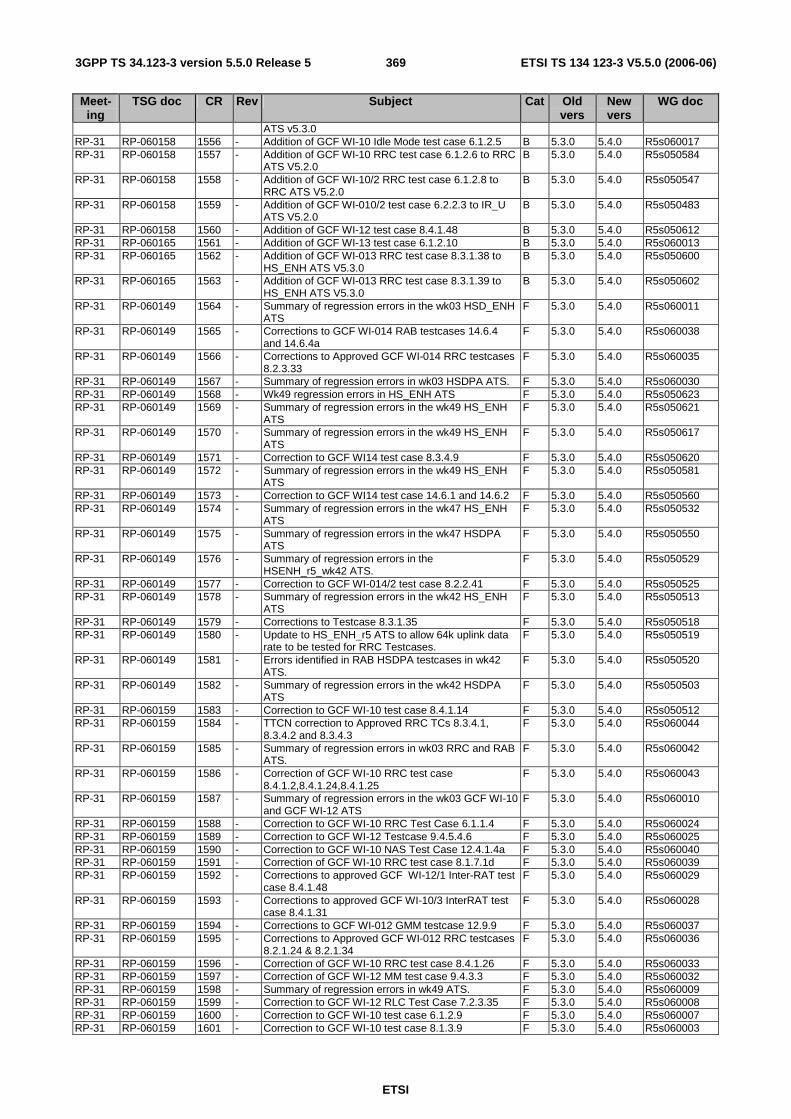
ETSI
ETSI TS 134 123-3 V5.5.0 (2006-06) 3693GPP TS 34.123-3 version 5.5.0 Release 5
Meet-ing
TSG doc CR Rev Subject Cat Old vers
New vers
WG doc
ATS v5.3.0 RP-31 RP-060158 1556 - Addition of GCF WI-10 Idle Mode test case 6.1.2.5 B 5.3.0 5.4.0 R5s060017 RP-31 RP-060158 1557 - Addition of GCF WI-10 RRC test case 6.1.2.6 to RRC
ATS V5.2.0 B 5.3.0 5.4.0 R5s050584
RP-31 RP-060158 1558 - Addition of GCF WI-10/2 RRC test case 6.1.2.8 to RRC ATS V5.2.0
B 5.3.0 5.4.0 R5s050547
RP-31 RP-060158 1559 - Addition of GCF WI-010/2 test case 6.2.2.3 to IR_U ATS V5.2.0
B 5.3.0 5.4.0 R5s050483
RP-31 RP-060158 1560 - Addition of GCF WI-12 test case 8.4.1.48 B 5.3.0 5.4.0 R5s050612 RP-31 RP-060165 1561 - Addition of GCF WI-13 test case 6.1.2.10 B 5.3.0 5.4.0 R5s060013 RP-31 RP-060165 1562 - Addition of GCF WI-013 RRC test case 8.3.1.38 to
HS_ENH ATS V5.3.0 B 5.3.0 5.4.0 R5s050600
RP-31 RP-060165 1563 - Addition of GCF WI-013 RRC test case 8.3.1.39 to HS_ENH ATS V5.3.0
B 5.3.0 5.4.0 R5s050602
RP-31 RP-060149 1564 - Summary of regression errors in the wk03 HSD_ENH ATS
F 5.3.0 5.4.0 R5s060011
RP-31 RP-060149 1565 - Corrections to GCF WI-014 RAB testcases 14.6.4 and 14.6.4a
F 5.3.0 5.4.0 R5s060038
RP-31 RP-060149 1566 - Corrections to Approved GCF WI-014 RRC testcases 8.2.3.33
F 5.3.0 5.4.0 R5s060035
RP-31 RP-060149 1567 - Summary of regression errors in wk03 HSDPA ATS. F 5.3.0 5.4.0 R5s060030 RP-31 RP-060149 1568 - Wk49 regression errors in HS_ENH ATS F 5.3.0 5.4.0 R5s050623 RP-31 RP-060149 1569 - Summary of regression errors in the wk49 HS_ENH
ATS F 5.3.0 5.4.0 R5s050621
RP-31 RP-060149 1570 - Summary of regression errors in the wk49 HS_ENH ATS
F 5.3.0 5.4.0 R5s050617
RP-31 RP-060149 1571 - Correction to GCF WI14 test case 8.3.4.9 F 5.3.0 5.4.0 R5s050620 RP-31 RP-060149 1572 - Summary of regression errors in the wk49 HS_ENH
ATS F 5.3.0 5.4.0 R5s050581
RP-31 RP-060149 1573 - Correction to GCF WI14 test case 14.6.1 and 14.6.2 F 5.3.0 5.4.0 R5s050560 RP-31 RP-060149 1574 - Summary of regression errors in the wk47 HS_ENH
ATS F 5.3.0 5.4.0 R5s050532
RP-31 RP-060149 1575 - Summary of regression errors in the wk47 HSDPA ATS
F 5.3.0 5.4.0 R5s050550
RP-31 RP-060149 1576 - Summary of regression errors in the HSENH_r5_wk42 ATS.
F 5.3.0 5.4.0 R5s050529
RP-31 RP-060149 1577 - Correction to GCF WI-014/2 test case 8.2.2.41 F 5.3.0 5.4.0 R5s050525 RP-31 RP-060149 1578 - Summary of regression errors in the wk42 HS_ENH
ATS F 5.3.0 5.4.0 R5s050513
RP-31 RP-060149 1579 - Corrections to Testcase 8.3.1.35 F 5.3.0 5.4.0 R5s050518 RP-31 RP-060149 1580 - Update to HS_ENH_r5 ATS to allow 64k uplink data
rate to be tested for RRC Testcases. F 5.3.0 5.4.0 R5s050519
RP-31 RP-060149 1581 - Errors identified in RAB HSDPA testcases in wk42 ATS.
F 5.3.0 5.4.0 R5s050520
RP-31 RP-060149 1582 - Summary of regression errors in the wk42 HSDPA ATS
F 5.3.0 5.4.0 R5s050503
RP-31 RP-060159 1583 - Correction to GCF WI-10 test case 8.4.1.14 F 5.3.0 5.4.0 R5s050512 RP-31 RP-060159 1584 - TTCN correction to Approved RRC TCs 8.3.4.1,
8.3.4.2 and 8.3.4.3 F 5.3.0 5.4.0 R5s060044
RP-31 RP-060159 1585 - Summary of regression errors in wk03 RRC and RAB ATS.
F 5.3.0 5.4.0 R5s060042
RP-31 RP-060159 1586 - Correction of GCF WI-10 RRC test case 8.4.1.2,8.4.1.24,8.4.1.25
F 5.3.0 5.4.0 R5s060043
RP-31 RP-060159 1587 - Summary of regression errors in the wk03 GCF WI-10 and GCF WI-12 ATS
F 5.3.0 5.4.0 R5s060010
RP-31 RP-060159 1588 - Correction to GCF WI-10 RRC Test Case 6.1.1.4 F 5.3.0 5.4.0 R5s060024 RP-31 RP-060159 1589 - Correction to GCF WI-12 Testcase 9.4.5.4.6 F 5.3.0 5.4.0 R5s060025 RP-31 RP-060159 1590 - Correction to GCF WI-10 NAS Test Case 12.4.1.4a F 5.3.0 5.4.0 R5s060040 RP-31 RP-060159 1591 - Correction of GCF WI-10 RRC test case 8.1.7.1d F 5.3.0 5.4.0 R5s060039 RP-31 RP-060159 1592 - Corrections to approved GCF WI-12/1 Inter-RAT test
case 8.4.1.48 F 5.3.0 5.4.0 R5s060029
RP-31 RP-060159 1593 - Corrections to approved GCF WI-10/3 InterRAT test case 8.4.1.31
F 5.3.0 5.4.0 R5s060028
RP-31 RP-060159 1594 - Corrections to GCF WI-012 GMM testcase 12.9.9 F 5.3.0 5.4.0 R5s060037 RP-31 RP-060159 1595 - Corrections to Approved GCF WI-012 RRC testcases
8.2.1.24 & 8.2.1.34 F 5.3.0 5.4.0 R5s060036
RP-31 RP-060159 1596 - Correction of GCF WI-10 RRC test case 8.4.1.26 F 5.3.0 5.4.0 R5s060033 RP-31 RP-060159 1597 - Correction of GCF WI-12 MM test case 9.4.3.3 F 5.3.0 5.4.0 R5s060032 RP-31 RP-060159 1598 - Summary of regression errors in wk49 ATS. F 5.3.0 5.4.0 R5s060009 RP-31 RP-060159 1599 - Correction to GCF WI-12 RLC Test Case 7.2.3.35 F 5.3.0 5.4.0 R5s060008 RP-31 RP-060159 1600 - Correction to GCF WI-10 test case 6.1.2.9 F 5.3.0 5.4.0 R5s060007 RP-31 RP-060159 1601 - Correction to GCF WI-10 test case 8.1.3.9 F 5.3.0 5.4.0 R5s060003
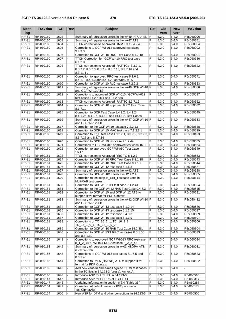
ETSI
ETSI TS 134 123-3 V5.5.0 (2006-06) 3703GPP TS 34.123-3 version 5.5.0 Release 5
Meet-ing
TSG doc CR Rev Subject Cat Old vers
New vers
WG doc
RP-31 RP-060159 1602 - Summary of regression errors in the wk49 IR_U ATS. F 5.3.0 5.4.0 R5s060006 RP-31 RP-060160 1603 - Summary of regression errors in the wk47 ATS. F 5.3.0 5.4.0 R5s050551 RP-31 RP-060160 1604 - TTCN correction to Approved GMM TC 12.4.2.4 F 5.3.0 5.4.0 R5s060004 RP-31 RP-060160 1605 - Corrections to GCF WI-012 approved testcases
9.4.3.3 F 5.3.0 5.4.0 R5s060002
RP-31 RP-060160 1606 - Correction to GCF WI-10 RRC Test Case 8.1.7.1c F 5.3.0 5.4.0 R5s060001 RP-31 RP-060160 1607 - TTCN Correction for GCF WI-10 RRC test case
6.1.2.8 F 5.3.0 5.4.0 R5s050586
RP-31 RP-060160 1608 - TTCN correction to Approved IRAT TCs 8.3.7.1, 8.3.7.2, 8.3.7.3, 8.3.7.4, 8.3.7.13, 8.3.7.16 and 8.3.11.1 .
F 5.3.0 5.4.0 R5s050622
RP-31 RP-060160 1609 - Correction to approved RRC test cases 8.1.6.3, 8.4.1.1, 8.4.1.3 and 8.4.1.29 on Wk49 ATS
F 5.3.0 5.4.0 R5s050571
RP-31 RP-060160 1610 - Correction to GCF WI 10 RLC testcase 7.2.2.2 F 5.3.0 5.4.0 R5s050583 RP-31 RP-060160 1611 - Summary of regression errors in the wk49 GCF WI-10
and GCF WI-12 ATS F 5.3.0 5.4.0 R5s050580
RP-31 RP-060160 1612 - Corrections to approved GCF WI-010 / GCF WI-012 test cases 14.2.51b.1 and 14.2.58a
F 5.3.0 5.4.0 R5s050597
RP-31 RP-060160 1613 - TTCN correction to Approved IRAT TC 8.3.7.16 F 5.3.0 5.4.0 R5s050552 RP-31 RP-060160 1614 - Correction to GCF WI-10 approved RRC Test Case
8.1.7.1d F 5.3.0 5.4.0 R5s050582
RP-31 RP-060160 1615 - Correction to GCF Test Case 8.4.1.2, 8.4.1.24, 8.4.1.25, 8.4.1.6, 8.4.1.8 and HSDPA Test Cases
F 5.3.0 5.4.0 R5s050545
RP-31 RP-060160 1616 - Summary of regression errors in the wk47 GCF WI-10 and GCF WI-12 ATS
F 5.3.0 5.4.0 R5s050533
RP-31 RP-060160 1617 - Correction to the GCF WI 10 testcase 7.2.3.13 F 5.3.0 5.4.0 R5s050538 RP-31 RP-060160 1618 - Correction to GCF WI 10 MAC test case 7.1.2.3.1 F 5.3.0 5.4.0 R5s050539 RP-31 RP-060160 1619 - Correction to IR_U test cases 8.3.7.1, 8.3.7.2, 8.3.7.3,
8.3.7.12 and 8.3.7.16 F 5.3.0 5.4.0 R5s050493
RP-31 RP-060160 1620 - Correction to GCF WI 10 test case 7.1.2.4a F 5.3.0 5.4.0 R5s050555 RP-31 RP-060160 1621 - Corrections to GCF WI-012 approved test case 16.3 F 5.3.0 5.4.0 R5s050554 RP-31 RP-060160 1622 - Correction to approved GCF WI-010 Test Case
16.1.1 F 5.3.0 5.4.0 R5s050549
RP-31 RP-060161 1623 - TTCN correction to Approved RRC TC 8.1.2.7 F 5.3.0 5.4.0 R5s050553 RP-31 RP-060161 1624 - Correction to GCF WI-10 RRC Test Case 8.3.1.18 F 5.3.0 5.4.0 R5s050543 RP-31 RP-060161 1625 - Correction to GCF WI-10 RRC Test Case 8.1.1.9 F 5.3.0 5.4.0 R5s050544 RP-31 RP-060161 1626 - Correction to GCF WI-12 test case 8.1.6.3 F 5.3.0 5.4.0 R5s050531 RP-31 RP-060161 1627 - Summary of regression errors in the wk42 ATS. F 5.3.0 5.4.0 R5s050528 RP-31 RP-060161 1628 - Correction to GCF WI-10/3 Testcase 12.4.2.4 F 5.3.0 5.4.0 R5s050505 RP-31 RP-060161 1629 - Correction to test step ts_Exit_Testcase used in
MultiRAB test cases F 5.3.0 5.4.0 R5s050514
RP-31 RP-060161 1630 - Correction to GCF WI-010/1 test case 7.1.2.4a F 5.3.0 5.4.0 R5s050524 RP-31 RP-060161 1631 - Correction to the GCF WI 12 NAS Test Case 9.4.3.3 F 5.3.0 5.4.0 R5s050515 RP-31 RP-060161 1632 - Correction to GCF WI 10 and GCF WI 12 ATS to
support IPv6 format for PDP Context F 5.3.0 5.4.0 R5s050521
RP-31 RP-060161 1633 - Summary of regression errors in the wk42 GCF WI-10 and GCF WI-12 ATS
F 5.3.0 5.4.0 R5s050482
RP-31 RP-060161 1634 - Correction to GCF WI-13 test case 8.1.2.14 F 5.3.0 5.4.0 R5s050526 RP-31 RP-060161 1635 - Correction to GCF WI-13 test case 8.1.2.15 F 5.3.0 5.4.0 R5s050527 RP-31 RP-060161 1636 - Correction to GCF WI-12 test case 9.4.3.3 F 5.3.0 5.4.0 R5s050509 RP-31 RP-060161 1637 - Correction to GCF WI-10 test case 8.1.3.9 F 5.3.0 5.4.0 R5s050507 RP-31 RP-060161 1638 - Corrections of TC_16_2_1, TC_16_2_2,
TC_16_1_9_1, TC_16_1_9_2 F 5.3.0 5.4.0 R5s050506
RP-31 RP-060161 1639 - Correction to GCF WI-10 RAB Test Case 14.2.38c F 5.3.0 5.4.0 R5s050504 RP-31 RP-060165 1640 - Correction to GCF WI 13/1 RRC testcases 8.3.1.38
and 8.3.1.39 F 5.3.0 5.4.0 R5s060023
RP-31 RP-060165 1641 - Corrections to Approved GCF WI-013 RRC testcase 8_1_2_14 & WI-014 RRC testcase 8_2_2_42
F 5.3.0 5.4.0 R5s060034
RP-31 RP-060165 1642 - Summary of regression errors in wk03 HSDPA ATS (GCF WI-13).
F 5.3.0 5.4.0 R5s060031
RP-31 RP-060165 1643 - Corrections to GCF WI-013 test cases 8.1.6.5 and 8.3.1.40
F 5.3.0 5.4.0 R5s050523
RP-31 RP-060165 1644 - Correction to Rel-5 (HSENH) ATS to support IPv6 format for PDP Context.
F 5.3.0 5.4.0 R5s050522
RP-31 RP-060162 1645 - Add new verified and e-mail agreed TTCN test cases in the TC lists in 34.123-3 (prose), Annex A
F 5.3.0 5.4.0 -
RP-31 RP-060166 1646 - Introduce ASP for HSUPA in 34.123-3 B 5.3.0 5.4.0 R5-060560 RP-31 RP-060147 1647 - Introduce ASP for HSDPA of LCR TDD B 5.3.0 5.4.0 R5-060317 RP-31 RP-060147 1648 - Updating Information in section 8.2.4 (Table 35 ) F 5.3.0 5.4.0 R5-060287 RP-31 RP-060154 1649 - Correction of default value for IXIT parameter
"px_CipherAlg". F 5.3.0 5.4.0 R5-060178
RP-31 RP-060154 1650 - New ASP for DTM and other corrections in 34.123-3 F 5.3.0 5.4.0 R5-060505
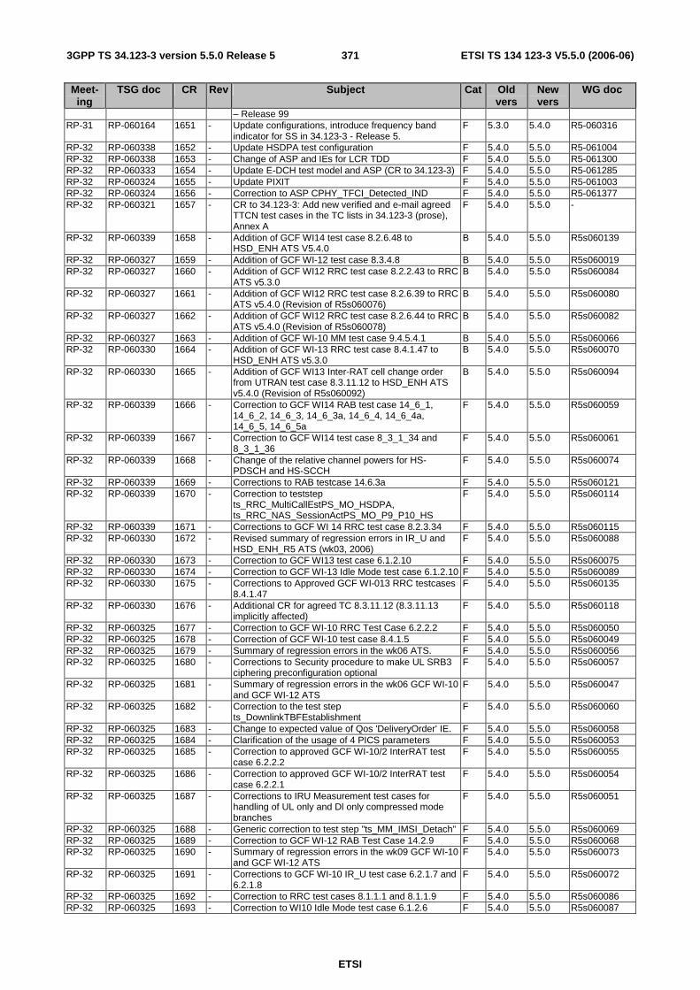
ETSI
ETSI TS 134 123-3 V5.5.0 (2006-06) 3713GPP TS 34.123-3 version 5.5.0 Release 5
Meet-ing
TSG doc CR Rev Subject Cat Old vers
New vers
WG doc
– Release 99 RP-31 RP-060164 1651 - Update configurations, introduce frequency band
indicator for SS in 34.123-3 - Release 5. F 5.3.0 5.4.0 R5-060316
RP-32 RP-060338 1652 - Update HSDPA test configuration F 5.4.0 5.5.0 R5-061004 RP-32 RP-060338 1653 - Change of ASP and IEs for LCR TDD F 5.4.0 5.5.0 R5-061300 RP-32 RP-060333 1654 - Update E-DCH test model and ASP (CR to 34.123-3) F 5.4.0 5.5.0 R5-061285 RP-32 RP-060324 1655 - Update PIXIT F 5.4.0 5.5.0 R5-061003 RP-32 RP-060324 1656 - Correction to ASP CPHY_TFCI_Detected_IND F 5.4.0 5.5.0 R5-061377 RP-32 RP-060321 1657 - CR to 34.123-3: Add new verified and e-mail agreed
TTCN test cases in the TC lists in 34.123-3 (prose), Annex A
F 5.4.0 5.5.0 -
RP-32 RP-060339 1658 - Addition of GCF WI14 test case 8.2.6.48 to HSD_ENH ATS V5.4.0
B 5.4.0 5.5.0 R5s060139
RP-32 RP-060327 1659 - Addition of GCF WI-12 test case 8.3.4.8 B 5.4.0 5.5.0 R5s060019 RP-32 RP-060327 1660 - Addition of GCF WI12 RRC test case 8.2.2.43 to RRC
ATS v5.3.0 B 5.4.0 5.5.0 R5s060084
RP-32 RP-060327 1661 - Addition of GCF WI12 RRC test case 8.2.6.39 to RRC ATS v5.4.0 (Revision of R5s060076)
B 5.4.0 5.5.0 R5s060080
RP-32 RP-060327 1662 - Addition of GCF WI12 RRC test case 8.2.6.44 to RRC ATS v5.4.0 (Revision of R5s060078)
B 5.4.0 5.5.0 R5s060082
RP-32 RP-060327 1663 - Addition of GCF WI-10 MM test case 9.4.5.4.1 B 5.4.0 5.5.0 R5s060066 RP-32 RP-060330 1664 - Addition of GCF WI-13 RRC test case 8.4.1.47 to
HSD_ENH ATS v5.3.0 B 5.4.0 5.5.0 R5s060070
RP-32 RP-060330 1665 - Addition of GCF WI13 Inter-RAT cell change order from UTRAN test case 8.3.11.12 to HSD_ENH ATS v5.4.0 (Revision of R5s060092)
B 5.4.0 5.5.0 R5s060094
RP-32 RP-060339 1666 - Correction to GCF WI14 RAB test case 14_6_1, 14_6_2, 14_6_3, 14_6_3a, 14_6_4, 14_6_4a, 14_6_5, 14_6_5a
F 5.4.0 5.5.0 R5s060059
RP-32 RP-060339 1667 - Correction to GCF WI14 test case 8_3_1_34 and 8_3_1_36
F 5.4.0 5.5.0 R5s060061
RP-32 RP-060339 1668 - Change of the relative channel powers for HS-PDSCH and HS-SCCH
F 5.4.0 5.5.0 R5s060074
RP-32 RP-060339 1669 - Corrections to RAB testcase 14.6.3a F 5.4.0 5.5.0 R5s060121 RP-32 RP-060339 1670 - Correction to teststep
ts_RRC_MultiCallEstPS_MO_HSDPA, ts_RRC_NAS_SessionActPS_MO_P9_P10_HS
F 5.4.0 5.5.0 R5s060114
RP-32 RP-060339 1671 - Corrections to GCF WI 14 RRC test case 8.2.3.34 F 5.4.0 5.5.0 R5s060115 RP-32 RP-060330 1672 - Revised summary of regression errors in IR_U and
HSD_ENH_R5 ATS (wk03, 2006) F 5.4.0 5.5.0 R5s060088
RP-32 RP-060330 1673 - Correction to GCF WI13 test case 6.1.2.10 F 5.4.0 5.5.0 R5s060075 RP-32 RP-060330 1674 - Correction to GCF WI-13 Idle Mode test case 6.1.2.10 F 5.4.0 5.5.0 R5s060089 RP-32 RP-060330 1675 - Corrections to Approved GCF WI-013 RRC testcases
8.4.1.47 F 5.4.0 5.5.0 R5s060135
RP-32 RP-060330 1676 - Additional CR for agreed TC 8.3.11.12 (8.3.11.13 implicitly affected)
F 5.4.0 5.5.0 R5s060118
RP-32 RP-060325 1677 - Correction to GCF WI-10 RRC Test Case 6.2.2.2 F 5.4.0 5.5.0 R5s060050 RP-32 RP-060325 1678 - Correction of GCF WI-10 test case 8.4.1.5 F 5.4.0 5.5.0 R5s060049 RP-32 RP-060325 1679 - Summary of regression errors in the wk06 ATS. F 5.4.0 5.5.0 R5s060056 RP-32 RP-060325 1680 - Corrections to Security procedure to make UL SRB3
ciphering preconfiguration optional F 5.4.0 5.5.0 R5s060057
RP-32 RP-060325 1681 - Summary of regression errors in the wk06 GCF WI-10 and GCF WI-12 ATS
F 5.4.0 5.5.0 R5s060047
RP-32 RP-060325 1682 - Correction to the test step ts_DownlinkTBFEstablishment
F 5.4.0 5.5.0 R5s060060
RP-32 RP-060325 1683 - Change to expected value of Qos 'DeliveryOrder' IE. F 5.4.0 5.5.0 R5s060058 RP-32 RP-060325 1684 - Clarification of the usage of 4 PICS parameters F 5.4.0 5.5.0 R5s060053 RP-32 RP-060325 1685 - Correction to approved GCF WI-10/2 InterRAT test
case 6.2.2.2 F 5.4.0 5.5.0 R5s060055
RP-32 RP-060325 1686 - Correction to approved GCF WI-10/2 InterRAT test case 6.2.2.1
F 5.4.0 5.5.0 R5s060054
RP-32 RP-060325 1687 - Corrections to IRU Measurement test cases for handling of UL only and Dl only compressed mode branches
F 5.4.0 5.5.0 R5s060051
RP-32 RP-060325 1688 - Generic correction to test step "ts_MM_IMSI_Detach" F 5.4.0 5.5.0 R5s060069 RP-32 RP-060325 1689 - Correction to GCF WI-12 RAB Test Case 14.2.9 F 5.4.0 5.5.0 R5s060068 RP-32 RP-060325 1690 - Summary of regression errors in the wk09 GCF WI-10
and GCF WI-12 ATS F 5.4.0 5.5.0 R5s060073
RP-32 RP-060325 1691 - Corrections to GCF WI-10 IR_U test case 6.2.1.7 and 6.2.1.8
F 5.4.0 5.5.0 R5s060072
RP-32 RP-060325 1692 - Correction to RRC test cases 8.1.1.1 and 8.1.1.9 F 5.4.0 5.5.0 R5s060086 RP-32 RP-060325 1693 - Correction to WI10 Idle Mode test case 6.1.2.6 F 5.4.0 5.5.0 R5s060087

ETSI
ETSI TS 134 123-3 V5.5.0 (2006-06) 3723GPP TS 34.123-3 version 5.5.0 Release 5
Meet-ing
TSG doc CR Rev Subject Cat Old vers
New vers
WG doc
RP-32 RP-060325 1694 - Correction to the IR_U test case 6.2.2.3 F 5.4.0 5.5.0 R5s060091 RP-32 RP-060325 1695 - Correction to SM GCF WI 10 test case 11.3.1 F 5.4.0 5.5.0 R5s060090 RP-32 RP-060325 1696 - Correction to GCF WI-12 Testcase 9.4.3.3 F 5.4.0 5.5.0 R5s060101 RP-32 RP-060326 1697 - Correction to GCF WI-12 Testcase 9.4.5.4.6 F 5.4.0 5.5.0 R5s060102 RP-32 RP-060326 1698 - Correction to GCF WI-10 Testcase 8.1.7.1c F 5.4.0 5.5.0 R5s060103 RP-32 RP-060326 1699 - Correction to GCF WI-15 Test Cases F 5.4.0 5.5.0 R5s060104 RP-32 RP-060326 1700 - TTCN correction to Approved RRC TCs 8.3.4.1,
8.3.4.2 and 8.3.4.3 F 5.4.0 5.5.0 R5s060096
RP-32 RP-060326 1701 - TTCN correction to Approved RRC TC 8.4.1.14 F 5.4.0 5.5.0 R5s060095 RP-32 RP-060326 1702 - Correction of approved IR_U test case 8.3.11.1. F 5.4.0 5.5.0 R5s060097 RP-32 RP-060326 1703 - Correction of approved HSD_ENH_R5 test cases
8.3.11.9, 8.3.11.13 and of 8.3.11.12 (under approval). F 5.4.0 5.5.0 R5s060098
RP-32 RP-060326 1704 - Correction to GCF WI-10 GMM test case 12.4.2.4 F 5.4.0 5.5.0 R5s060110 RP-32 RP-060326 1705 - Correction in TTCN for RLC Test cases 7.2.3.21,
7.2.3.22 and 7.2.3.24 F 5.4.0 5.5.0 R5s060109
RP-32 RP-060326 1706 - Correction to RRC GCF WI 12 test case 8.3.1.30 F 5.4.0 5.5.0 R5s060106 RP-32 RP-060326 1707 - Corrections to RAB testcase 14.2.41 F 5.4.0 5.5.0 R5s060120 RP-32 RP-060326 1708 - Correction to GCF WI-10 RRC Test Case 8.1.1.9 F 5.4.0 5.5.0 R5s060119 RP-32 RP-060326 1709 - Correction to the constraints used for the Radio
Bearer Reconfiguration Message F 5.4.0 5.5.0 R5s060113
RP-32 RP-060326 1710 - Correction to RRC test cases 8.3.1.21 and 8.3.2.11 F 5.4.0 5.5.0 R5s060112 RP-32 RP-060326 1711 - Summary of regression errors in the wk11 ATS. F 5.4.0 5.5.0 R5s060111 RP-32 RP-060326 1712 - Corrections to TTCN test cases due to the review of
34.123-2 and, related, the implementation of test case selection expressions in the TTCN.
F 5.4.0 5.5.0 R5s060116
RP-32 RP-060326 1713 - Empty all PCOs when TC begins F 5.4.0 5.5.0 R5s060064 RP-32 RP-060326 1714 - Correction to QOS parameters for UMTS only
mobiles F 5.4.0 5.5.0 R5s060041
RP-32 RP-060326 1715 - Correction to GCF Test Case 8.4.1.25 F 5.4.0 5.5.0 R5s060141 RP-32 RP-060326 1716 - Correction to GCF WI-10 Testcase 7.2.3.21 F 5.4.0 5.5.0 R5s060126 RP-32 RP-060327 1717 - Correction to GCF WI-12 Testcase 9.4.3.3 F 5.4.0 5.5.0 R5s060127 RP-32 RP-060327 1718 - Correction to GCF WI-10 IR-U Test Case 6.2.2.3 F 5.4.0 5.5.0 R5s060128 RP-32 RP-060327 1719 - Correction to the RRC test case 6.1.2.8 F 5.4.0 5.5.0 R5s060123 RP-32 RP-060327 1720 - Correction to GCF WI-12 NAS Test Case 9.4.3.3 F 5.4.0 5.5.0 R5s060122 RP-32 RP-060327 1721 - Correction to GCF WI-10 SMS Test Case 16.x F 5.4.0 5.5.0 R5s060136 RP-32 RP-060327 1722 - Correction to the IR_U test case 8.3.11.1 F 5.4.0 5.5.0 R5s060130 RP-32 RP-060327 1723 - Correction to the approved IR_U test cases 8.3.7.1
and 8.3.7.3 F 5.4.0 5.5.0 R5s060131
RP-32 RP-060327 1724 - Correction to the GCF WI-12 test case 8.4.1.48 F 5.4.0 5.5.0 R5s060134 RP-32 RP-060327 1725 - Correction to the common security teststeps to add
the default test step F 5.4.0 5.5.0 R5s060133
RP-32 RP-060327 1726 - Correction to Cell Broadcast test case 16.3 F 5.4.0 5.5.0 R5s060125 RP-32 RP-060327 1727 - Correction to the RRC test case 8.1.1.9 F 5.4.0 5.5.0 R5s060124 RP-32 RP-060327 1728 - Correction to the RRC compressed mode testcases F 5.4.0 5.5.0 R5s060132 RP-32 RP-060327 1729 - Correction of erroneous determination of OP-Mode in
multiple ATSs F 5.4.0 5.5.0 R5s060117
ETSI
ETSI TS 134 123-3 V5.5.0 (2006-06) 3733GPP TS 34.123-3 version 5.5.0 Release 5
History
Document history
V5.0.0 March 2005 Publication
V5.1.0 June 2005 Publication
V5.2.0 October 2005 Publication
V5.3.0 December 2005 Publication
V5.4.0 March 2006 Publication
V5.5.0 June 2006 Publication