TS 129 303 - V8.0.0 - Universal Mobile Telecommunications ... · PDF fileUniversal Mobile...
27
ETSI TS 129 303 V8.0.0 (2009-01) Technical Specification Universal Mobile Telecommunications System (UMTS); LTE; Domain Name System Procedures (3GPP TS 29.303 version 8.0.0 Release 8)
Transcript of TS 129 303 - V8.0.0 - Universal Mobile Telecommunications ... · PDF fileUniversal Mobile...

ETSI TS 129 303 V8.0.0 (2009-01)
Technical Specification
Universal Mobile Telecommunications System (UMTS);LTE;
Domain Name System Procedures (3GPP TS 29.303 version 8.0.0 Release 8)

ETSI
ETSI TS 129 303 V8.0.0 (2009-01) 1 3GPP TS 29.303 version 8.0.0 Release 8
Reference DTS/TSGC-0429303v800
Keywords LTE, UMTS
ETSI
650 Route des Lucioles F-06921 Sophia Antipolis Cedex - FRANCE
Tel.: +33 4 92 94 42 00 Fax: +33 4 93 65 47 16
Siret N° 348 623 562 00017 - NAF 742 C
Association à but non lucratif enregistrée à la Sous-Préfecture de Grasse (06) N° 7803/88
Important notice
Individual copies of the present document can be downloaded from: http://www.etsi.org
The present document may be made available in more than one electronic version or in print. In any case of existing or perceived difference in contents between such versions, the reference version is the Portable Document Format (PDF).
In case of dispute, the reference shall be the printing on ETSI printers of the PDF version kept on a specific network drive within ETSI Secretariat.
Users of the present document should be aware that the document may be subject to revision or change of status. Information on the current status of this and other ETSI documents is available at
http://portal.etsi.org/tb/status/status.asp
If you find errors in the present document, please send your comment to one of the following services: http://portal.etsi.org/chaircor/ETSI_support.asp
Copyright Notification
No part may be reproduced except as authorized by written permission. The copyright and the foregoing restriction extend to reproduction in all media.
© European Telecommunications Standards Institute 2009.
All rights reserved.
DECTTM, PLUGTESTSTM, UMTSTM, TIPHONTM, the TIPHON logo and the ETSI logo are Trade Marks of ETSI registered for the benefit of its Members.
3GPPTM is a Trade Mark of ETSI registered for the benefit of its Members and of the 3GPP Organizational Partners. LTE™ is a Trade Mark of ETSI currently being registered
for the benefit of its Members and of the 3GPP Organizational Partners. GSM® and the GSM logo are Trade Marks registered and owned by the GSM Association.

ETSI
ETSI TS 129 303 V8.0.0 (2009-01) 2 3GPP TS 29.303 version 8.0.0 Release 8
Intellectual Property Rights IPRs essential or potentially essential to the present document may have been declared to ETSI. The information pertaining to these essential IPRs, if any, is publicly available for ETSI members and non-members, and can be found in ETSI SR 000 314: "Intellectual Property Rights (IPRs); Essential, or potentially Essential, IPRs notified to ETSI in respect of ETSI standards", which is available from the ETSI Secretariat. Latest updates are available on the ETSI Web server (http://webapp.etsi.org/IPR/home.asp).
Pursuant to the ETSI IPR Policy, no investigation, including IPR searches, has been carried out by ETSI. No guarantee can be given as to the existence of other IPRs not referenced in ETSI SR 000 314 (or the updates on the ETSI Web server) which are, or may be, or may become, essential to the present document.
Foreword This Technical Specification (TS) has been produced by ETSI 3rd Generation Partnership Project (3GPP).
The present document may refer to technical specifications or reports using their 3GPP identities, UMTS identities or GSM identities. These should be interpreted as being references to the corresponding ETSI deliverables.
The cross reference between GSM, UMTS, 3GPP and ETSI identities can be found under http://webapp.etsi.org/key/queryform.asp.

ETSI
ETSI TS 129 303 V8.0.0 (2009-01) 3 3GPP TS 29.303 version 8.0.0 Release 8
Contents
Intellectual Property Rights ................................................................................................................................2
Foreword.............................................................................................................................................................2
Foreword.............................................................................................................................................................5
1 Scope ........................................................................................................................................................6
2 References ................................................................................................................................................6
3 Definitions, symbols and abbreviations ...................................................................................................6 3.1 Definitions..........................................................................................................................................................6 3.2 Abbreviations .....................................................................................................................................................7
4 General DNS Based Node Selection Description ....................................................................................7 4.1 Resource Records ...............................................................................................................................................7 4.1.1 A and AAAA ................................................................................................................................................7 4.1.2 NAPTR .........................................................................................................................................................7 4.1.3 SRV ..............................................................................................................................................................7 4.2 Selecting Domain Names ...................................................................................................................................8 4.3 Identifying Nodes, Services and Protocols.........................................................................................................8 4.3.1 IETF RFC 3958 Service and Protocol service names for 3GPP ...................................................................8 4.3.2 Identification of node names.........................................................................................................................8 4.3.3 Services from node names ............................................................................................................................9 4.3.3.1 General ....................................................................................................................................................9 4.3.3.2 Procedure ................................................................................................................................................9 4.3.3.3 Services of a PGW from PGW node name ...........................................................................................10 4.3.3.4 Services of a MME from MME node name (or GUTI).........................................................................10 4.3.3.5 Services of an SGSN from a P-TMSI ...................................................................................................10
5 Procedures for EPC Node Discovery and Selection...............................................................................11 5.1 Procedures for Discovering and Selecting a PGW ...........................................................................................11 5.1.1 Discovering a PGW for a 3GPP Access .....................................................................................................11 5.1.1.1 General ..................................................................................................................................................11 5.1.1.2 Discovering a PGW for a 3GPP Access - S8/Gp roaming case ............................................................11 5.1.1.3 Discovering a PGW for a 3GPP Access - S5/Gn intra-operator existing PDN.....................................12 5.1.1.4 Discovering a PGW for a 3GPP Access - S5/Gn intra-operator initial attach.......................................12 5.1.2 Discovering a PGW for a non-3GPP Access with Network Based Mobility Management........................13 5.1.2.1 Discovering a PGW for a non-3GPP Access – S2a/S2b initial attach for roaming and non-
roaming .................................................................................................................................................13 5.1.2.2 Discovering a PGW for a non-3GPP Access – S2a/S2b initial attach and chained S2a/S2b with
GTP or PMIPv6 based S8 .....................................................................................................................13 5.2 Procedures for Discovering and Selecting a SGW ...........................................................................................13 5.2.1 General........................................................................................................................................................13 5.2.2 SGW Selection during TAU with SGW change - 3GPP roaming case ......................................................14 5.2.3 SGW Selection during TAU with SGW change - non-roaming case .........................................................14 5.3 Procedures for Discovering and Selecting a PGW and SGW ..........................................................................15 5.4 Procedures for Discovering and Selecting an MME ........................................................................................15 5.5 Procedures for Discovering and Selecting an SGSN........................................................................................16 5.5.1 General........................................................................................................................................................16 5.5.2 SGSN initial target selection based on RAI................................................................................................16 5.5.3 SGSN initial target selection based on RNC-ID (UTRAN target)..............................................................17
Annex A (Informative): Examples.........................................................................................................18
Annex B (Normative): DNS procedures clarifications ......................................................................19
B.1 DNS RFC procedures general clarifications ..........................................................................................19
B.2 DNS procedures 3GPP clarifications on S-NAPTR...............................................................................19

ETSI
ETSI TS 129 303 V8.0.0 (2009-01) 4 3GPP TS 29.303 version 8.0.0 Release 8
Annex C (Informative): DNS Pseudo-Code..........................................................................................20
C.1 S-NAPTR procedure base pseudo-code .................................................................................................20
C.2 S-NAPTR procedure - no topon.............................................................................................................21
C.3 S-NAPTR procedure candidate list ........................................................................................................22
C.4 S-NAPTR procedure pseudo-code with topon.......................................................................................23
Annex D (Informative): Change history ...............................................................................................25
History ..............................................................................................................................................................26

ETSI
ETSI TS 129 303 V8.0.0 (2009-01) 5 3GPP TS 29.303 version 8.0.0 Release 8
Foreword This Technical Specification has been produced by the 3rd Generation Partnership Project (3GPP).
The contents of the present document are subject to continuing work within the TSG and may change following formal TSG approval. Should the TSG modify the contents of the present document, it will be re-released by the TSG with an identifying change of release date and an increase in version number as follows:
Version x.y.z
where:
x the first digit:
1 presented to TSG for information;
2 presented to TSG for approval;
3 or greater indicates TSG approved document under change control.
y the second digit is incremented for all changes of substance, i.e. technical enhancements, corrections, updates, etc.
z the third digit is incremented when editorial only changes have been incorporated in the document.

ETSI
ETSI TS 129 303 V8.0.0 (2009-01) 6 3GPP TS 29.303 version 8.0.0 Release 8
1 Scope The present document describes Domain Name System (DNS) Procedures for the Evolved Packet System. This document covers the Evolved Packet Core gateway node selection using DNS (e.g. SGW and PGW nodes) excluding all User Equipment (UE) initiated DNS-based discovery and selection procedures.
2 References The following documents contain provisions which, through reference in this text, constitute provisions of the present document.
• References are either specific (identified by date of publication, edition number, version number, etc.) or non-specific.
• For a specific reference, subsequent revisions do not apply.
• For a non-specific reference, the latest version applies. In the case of a reference to a 3GPP document (including a GSM document), a non-specific reference implicitly refers to the latest version of that document in the same Release as the present document.
[1] 3GPP TR 21.905: "Vocabulary for 3GPP Specifications".
[2] IETF RFC 1034:"DOMAIN NAMES - CONCEPTS AND FACILITIES".
[3] IETF RFC 1035:"DOMAIN NAMES - IMPLEMENTATION AND SPECIFICATION".
[4] 3GPP TS 23.003: "Numbering, addressing and identification".
[5] GSMA PRD IR.67 – "DNS Guidelines for Operators" Version 2.1.0.
[6] IETF RFC 3596: "DNS Extensions to Support IP Version 6".
[7] IETF RFC 3403: " Dynamic Delegation Discovery System (DDDS) Part Three: The Domain Name System (DNS) Database".
[8] IETF RFC 2782: "A DNS RR for specifying the location of services (DNS SRV)".
[9] IETF RFC 3958: "Domain-Based Application Service Location Using SRV RRs and the Dynamic Delegation Discovery Service (DDDS)".
[10] IETF RFC 3401: "Dynamic Delegation Discovery System (DDDS) Part One: The Comprehensive DDDS".
[11] 3GPP TS 23.401: "GPRS enhancements for E-UTRAN access ".
[12] 3GPP TS 25.413: "UTRAN Iu interface RANAP signalling".
[13] IETF RFC 2671: "Extension Mechanisms for DNS (EDNS0)".
[14] IETF RFC 3402: "Dynamic Delegation Discovery System (DDDS) Part Two: The Algorithm".
3 Definitions, symbols and abbreviations
3.1 Definitions For the purposes of the present document, the terms and definitions given in 3GPP TR 21.905 [1] and the following apply. A term defined in the present document takes precedence over the definition of the same term, if any, in 3GPP TR 21.905 [1].

ETSI
ETSI TS 129 303 V8.0.0 (2009-01) 7 3GPP TS 29.303 version 8.0.0 Release 8
Domain Name System as defined in IETF RFC 1034 [2], IETF RFC 1035[3], and as used in 3GPP in 3GPP TS 23.003 [4] and GSMA PRD IR.67 [5]
3.2 Abbreviations For the purposes of the present document, the abbreviations given in 3GPP TR 21.905[1] and the following apply. An abbreviation defined in the present document takes precedence over the definition of the same abbreviation, if any, in 3GPP TR 21.905 [1].
DNS Domain Name System DDDS Dynamic Delegation Discovery Service FQDN Fully Qualified Domain Name GUTI Globally Unique Temporary Identity PGW PDN Gateway SGW Serving Gateway TAI Tracking Area Identity TAU Tracking Area Update
4 General DNS Based Node Selection Description
4.1 Resource Records
4.1.1 A and AAAA
The A resource record is used to define IPv4 host address corresponding to fully qualified name of the host as defined in IETF RFC 1035 [3]. The AAAA resource record is used to define IPv6 host address corresponding to fully qualified name of the host as defined in IETF RFC 3596 [6].
It should be noted that in DNS A or AAAA record names, in general, represent a host and its "equivalent" interface. Host names, in general, cannot be used as node names. A node may need to have more than one host name for the simple reason that it can have multiple interfaces for different purposes.
4.1.2 NAPTR
The NAPTR resource record is defined in IETF RFC 3403 [7] and is a powerful tool that allows DNS to be used to lookup services for a wide variety of resource names, which are not in domain name syntax. NAPTR would be used by a client program to rewrite a string into a domain name. The rewrite process is controlled by flags that provide information on how to communicate with the host at the domain name that was the result of the rewrite. If DNS returns multiple NAPTR resource records those can be prioritized using embedded order and preference values defined by the DNS administrator.
The S-NAPTR procedure i.e., the "Straightforward-NAPTR" procedure, is defined in IETF RFC 3958 [9] and describes a Dynamic Delegation Discovery System (DDDS) [10] application procedures on how to resolve a domain name, application service name, and application protocol dynamically to target server and port by using both NAPTR and SRV (see IETF RFC 2782 [8]) resource records. The S-NAPTR also simplifies the use of NAPTR by limiting the NAPTR flags only to "a", "s" and "". Furthermore, only NAPTR "replacement" expressions are allowed, not "regular expressions", during the rewrite process. The changes compared to IETF RFC 3403 [7] NAPTR usage are procedural and are limited only to the resolver. The S-NAPTR use of the NAPTR resource record is exactly the same as defined in IETF RFC 3403 [7] from the DNS server and DNS infrastructure point of view. Additional information on S-NAPTR usage is provided in Annex B and Annex C.
4.1.3 SRV
The SRV resource record is defined in IETF RFC 2782 [8] and allows DNS administrators to use pool of servers for a single domain, to move services from host to host, and to designate some hosts as primary servers for a service from a
ETSI
ETSI TS 129 303 V8.0.0 (2009-01) 8 3GPP TS 29.303 version 8.0.0 Release 8
pool of hosts. A resolver can ask for a specific service/protocol combination for a specific domain name and get back a Fully Qualified Domain Names (FQDN) of any available servers.
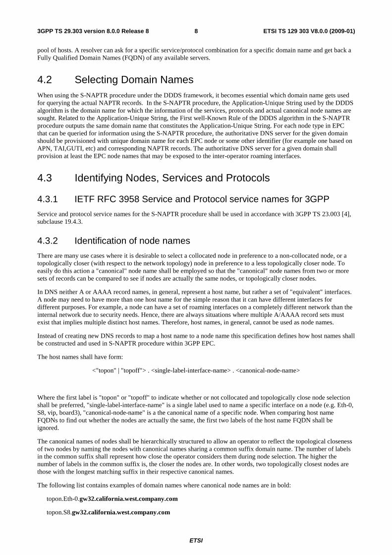
4.2 Selecting Domain Names When using the S-NAPTR procedure under the DDDS framework, it becomes essential which domain name gets used for querying the actual NAPTR records. In the S-NAPTR procedure, the Application-Unique String used by the DDDS algorithm is the domain name for which the information of the services, protocols and actual canonical node names are sought. Related to the Application-Unique String, the First well-Known Rule of the DDDS algorithm in the S-NAPTR procedure outputs the same domain name that constitutes the Application-Unique String. For each node type in EPC that can be queried for information using the S-NAPTR procedure, the authoritative DNS server for the given domain should be provisioned with unique domain name for each EPC node or some other identifier (for example one based on APN, TAI,GUTI, etc) and corresponding NAPTR records. The authoritative DNS server for a given domain shall provision at least the EPC node names that may be exposed to the inter-operator roaming interfaces.
4.3 Identifying Nodes, Services and Protocols
4.3.1 IETF RFC 3958 Service and Protocol service names for 3GPP
Service and protocol service names for the S-NAPTR procedure shall be used in accordance with 3GPP TS 23.003 [4], subclause 19.4.3.
4.3.2 Identification of node names
There are many use cases where it is desirable to select a collocated node in preference to a non-collocated node, or a topologically closer (with respect to the network topology) node in preference to a less topologically closer node. To easily do this action a "canonical" node name shall be employed so that the "canonical" node names from two or more sets of records can be compared to see if nodes are actually the same nodes, or topologically closer nodes.
In DNS neither A or AAAA record names, in general, represent a host name, but rather a set of "equivalent" interfaces. A node may need to have more than one host name for the simple reason that it can have different interfaces for different purposes. For example, a node can have a set of roaming interfaces on a completely different network than the internal network due to security needs. Hence, there are always situations where multiple A/AAAA record sets must exist that implies multiple distinct host names. Therefore, host names, in general, cannot be used as node names.
Instead of creating new DNS records to map a host name to a node name this specification defines how host names shall be constructed and used in S-NAPTR procedure within 3GPP EPC.
The host names shall have form:
<"topon" | "topoff"> . <single-label-interface-name> . <canonical-node-name>
Where the first label is "topon" or "topoff" to indicate whether or not collocated and topologically close node selection shall be preferred, "single-label-interface-name" is a single label used to name a specific interface on a node (e.g. Eth-0, S8, vip, board3), "canonical-node-name" is a the canonical name of a specific node. When comparing host name FQDNs to find out whether the nodes are actually the same, the first two labels of the host name FQDN shall be ignored.
The canonical names of nodes shall be hierarchically structured to allow an operator to reflect the topological closeness of two nodes by naming the nodes with canonical names sharing a common suffix domain name. The number of labels in the common suffix shall represent how close the operator considers them during node selection. The higher the number of labels in the common suffix is, the closer the nodes are. In other words, two topologically closest nodes are those with the longest matching suffix in their respective canonical names.
The following list contains examples of domain names where canonical node names are in bold:
topon.Eth-0.gw32.california.west.company.com
topon.S8.gw32.california.west.company.com

ETSI
ETSI TS 129 303 V8.0.0 (2009-01) 9 3GPP TS 29.303 version 8.0.0 Release 8
topon.vip.sgw3.oregon.west.company.com
topon.board3.pgw1.cluster1.net27.operator.com
topon.S5.gw4.cluster1.net27.operator.com
topon.board3.pgw1.cluster2.net27.operator.com
In the examples above, "Eth-0.gw32.california.west.company.com" and "S8.gw32.california.west.company.com" are two different interfaces on the same node, "gw32.california.west.company.com". On the other hand, "gw4.cluster1.net27.operator.com" is topologically closer to "pgw1.cluster1.net27.operator.com" (they are both connected to the "cluster1.net27.operator.com" subnetwork) than to "pgw1.cluster2.net27.operator.com" (only connected to the wider "net.27.operator.com" subnetwork.)
Interface names and node names do NOT identify a function in the procedures here. The interface is part of the natural hierarchy within a node and the host name is already returned with the existing DNS records. The approach here is believed to be simpler and more logical to maintain than additional DNS records.
The topologically aware naming restriction shall be placed only on all targets pointing to A/AAAA record sets from the S-NAPTR procedure. This restriction shall NOT apply to any other records the operator may be using.
A NAPTR with flag "a" will have a replacement target pointing to the A/AAAA record directly, thus the topologically aware naming restriction applies to the NAPTR record with a flag "a". For the flag "s" case the topologically aware naming restriction applies to the targets in the SRV record, and not the NAPTR record replacement target. For the empty flag "" case the topologically aware naming does not apply restriction. After successfully completing the S-NAPTR procedure the operator is free to add another layer of indirection using a CNAME record.
Topological matching with "topon" shall have higher importance in ordering which DNS records are used than the S-NAPTR ordering. Approximately, collocated sets of nodes have highest importance, then sets of nodes with the most labels in their common suffix, then second most number of labels and so on. Additional clarifications on how S-NAPTR is employed in the context of 3GPP EPC node usage and specifically how topological matching using the "topon" label interacts with S-NAPTR ordering is provided in Annex C.4.
4.3.3 Services from node names
4.3.3.1 General
There are potential use cases where a node has a logical name of a peer or other identifier but does not have the protocols it supports. The NAPTR record for any of the services can be provisioned at the nodes logical name. The node logical name here equals to the domain name under which NAPTR records are provisioned. This allows any peer to discover the available services of any other peer based on node"s logical name.
4.3.3.2 Procedure
These procedures are employed when any core network node has the FQDN of an entity and needs to find one or more services at that entity.
NOTE: There are three likely sources of the entity name. O&M provisioned, 3GPP specified based on some other identifier (such as GUTI, TAC, IMSI, MISDN etc.), or the canonical node name obtained from the S-NAPTR. Note that a node can have more than one name but there should be only one canonical name. (CNAME records can be used to create aliases for the canonical name)
The S-NAPTR procedure requires that DNS NAPTR records shall be consistently provisioned as described in IETF RFC 3958 [9]. This means a NAPTR record for each protocol using "a" flag and the service field populated with the service and proto value may be provisioned. If a more sophisticated load balancing or non standard ports are desired, NAPTR with "s" flag for each protocol and the corresponding SRV records with relative weighting for each interface need to be provisioned. NAPTR records with empty "" flag records may also be used.
A DNS resolver that intends to use the S-NAPTR procedure shall use the FQDN of the node as the Application-Unique String. If all protocols are desired, then the resolver simply runs the S-NAPTR procedure as if all protocols match.
The S-NAPTR procedure logically outputs a list of host names each with a service, protocol, port and a list of IPv4 and IPv6 addresses. This list can be obtained one host name at a time, in a procedure similar to Annex C.2, or a complete

ETSI
ETSI TS 129 303 V8.0.0 (2009-01) 103GPP TS 29.303 version 8.0.0 Release 8
ordered list of all nodes, in a procedure similar to Annex C.3. Such a complete list obtained from an S-NAPTR procedure is referred here as a candidate list.
4.3.3.3 Services of a PGW from PGW node name
An UE with both a 3GPP access capability and non-3GPP access capability can roam in and out of the 3GPP network while maintaining the same PDN connection.
To support roaming the HSS (or AAA) server can have a FQDN of a particular PGW node. One reason for using a FQDN instead of an IP address is that a PGW can be multihomed (i.e. more than one IP address). A possible use case is when the PGW interface needs to be changed between PMIP � GTP. Even if each interface type only uses one IP address, the different interfaces can still use different IP addresses. For Example, roaming and non-roaming interfaces are likely to be separated from each other using firewall or other mechanisms.
To resolve the allowed PMIPv6 interfaces the S-NAPTR procedure shall be used with the "Service Parameters" of
"x-3gpp-pgw:x-s5-pmip" , "x-3gpp-pgw:x-s8-pmip" etc.
as defined in subclause 19.4.3 of 3GPP TS 23.003 [4], and the Application-Unique String set to the FQDN of the node. For example, an operator might provision a PGW name at:
gw1.pgw.nodes.epc.mnc<MNC>.mcc<MCC>.3gppnetwork.org
Similarly for the GTP interfaces the S-NAPTR procedure shall use "Service Parameters" of
"x-3gpp-pgw:x-s5-gtp" , "x-3gpp-pgw:x-s8-gtp" etc.
as defined in subclause 19.4.3 of 3GPP TS 23.003 [4], and the Application-Unique String set to the FQDN of the specific PGW node. It is also possible to leave "Service Parameters" unspecified in the S-NAPTR procedure in order to identify all interfaces for all supported protocols.
The S-NAPTR procedure logically outputs a list of host names each with a service, protocol, port and a list of IPv4 and IPv6 addresses. This is a "candidate" list of services and interfaces of that PGW (see Annex C.2 for a more detailed description of a candidate list).
4.3.3.4 Services of a MME from MME node name (or GUTI)
There are procedures where the old MME must be contacted by the new MME. The MME node FQDN shall be constructed as defined in subclause 19.4.2.4 of 3GPP TS 23.003 [4].
Operators should provision NAPTR records under that FQDN for all interfaces for the MME, if DNS is used for resolving MME addresses.
So to find all services of an MME based on the GUTI the S-NAPTR procedure shall be prefixedwith "Service Parameters" of
" x-3gpp-mme:x-s10 ", "x-3gpp-mme:x-s11", etc.
and set the Application-Unique String to the FQDN as defined in subclause 19.4.2.4 of 3GPP TS 23.003 [4], with the initial query targeted at the fully qualified domain name of the node to find the s10, s11, etc. interfaces (or all protocols can be done at once to identify all interfaces).
4.3.3.5 Services of an SGSN from a P-TMSI
There are procedures where the source SGSN must be contacted by the target MME or a target Release-8 SGSN.
During a mobility procedure towards a new core network node, a UE served by a SGSN has a previously assigned P-TMSI by the source SGSN. A pre-Release-8 UE will provide the P-TMSI. A Release-8 UE will map P-TMSI to a derived GUTI using the procedure described in Annex H of 3GPP TS 23.401 [11]. That P-TMSI will be delivered to the target node when using the Gn/Gp interfaces and the GUTI will be delivered when using S3/S4.
The target Release-8 core network node extracts the source's NRI, RAC, LAC, MNC and MCC from the P-TMSI (or GUTI based on the procedure described in Annex H of 3GPP TS 23.401 [11]).

ETSI
ETSI TS 129 303 V8.0.0 (2009-01) 113GPP TS 29.303 version 8.0.0 Release 8
The S-NAPTR procedure for finding the old SGSN services and interfaces from the P-TMSI is started with "Service Parameters" of
"x-3gpp-sgsn:x-gn", "x-3gpp-sgsn:x-gp", "x-3gpp-sgsn:x-s3", "x-3gpp-sgsn:x-s4"
as defined in 3GPP TS 23.003 [4] and setting the Application-Unique String to the FQDN based on NRI, RAC, LAC, MNC and MCC as defined in 3GPP TS 23.003 [4]:
nri-sgsn<NRI>.rac<RAC>.lac<LAC>.rac.epc.mnc<MNC>.mcc<MCC>.3gppnetwork.org
Editor's Note: New sections within section 19.4 of 3GPP TS 23.003 will be added in a later CR to define a FQDN of proposed form. The FQDN can then be removed from the present document as the reference would suffice.
NOTE 1: In the event a valid NRI is not available then the first label "nri-sgsn<NRI>" shall be excluded from FQDN.
NOTE 2: Service Parameters are limited to those supported by the node doing the search.
The S-NAPTR procedure returns either one SRV record set or one A/AAAA record set.
Operators will provision NAPTR records that FQDN for all valid interfaces of a Release-8 SGSN.
For a pre-Release-8 target node i.e. a UE moving from eUTRAN to pre-Release-8 UTRAN/GERAN the UE will provide a derived P-TMSI based on a GUTI (See Annex H of 3GPP TS 23.401 [11]). As a result the source MME or Release-8 SGSN looks like a pre-Release-8 SGSN to a pre-Release-8 target node. For pre-Release-8 compatibility operators would continue to provision A/AAAA records as described in Annex C.1 of 3GPP TS 23.003 [4] for the corresponding Gn/Gp interfaces regardless of whether the source SGSN is pre-Release-8 or not.
NOTE 3: Gn/Gp interfaces are provisioned redundantly for both ".gprs" and ".3gppnetwork.org" top level domains during the transition to Release-8 to allow a gradual forward migration to 3ggpnetwork.org while still supporting existing pre-Release-8 usage.
5 Procedures for EPC Node Discovery and Selection
5.1 Procedures for Discovering and Selecting a PGW
5.1.1 Discovering a PGW for a 3GPP Access
5.1.1.1 General
The procedures here give a list of possible PGWs and their interfaces that serve a particular APN. This is very similar to the existing function that resolves the GGSN IP address based on an APN.
However, the Release-8 behaviour includes more functionally than pre-Release-8 systems since the PGW now can support more than one protocol and there is sometimes a desire to have the PGW and SGW collocated or topologically close to each other (with respect to the network topology), if possible. New DNS records are required to distinguish between different protocols and interfaces and assist in the more complicated selections.
The authoritative DNS server responsible for the "apn.epc.mnc<MNC>.mcc<MCC>.3gppnetwork.org" domain shall provision NAPTR records for the given APN and corresponding PGWs under the FQDN:
<APN-NI>.apn.epc.mnc<MNC>.mcc<MCC>.3gppnetwork.org
5.1.1.2 Discovering a PGW for a 3GPP Access - S8/Gp roaming case
Assuming the SGW is in the visiting network and the APN to be selected is in the home network then the S-NAPTR procedure shall use "Service Parameters" of
"x-3gpp-pgw:x-s8-gtp", "x-3gpp-pgw:x-s8-pmip", "x-3gpp-ggsn:x-gp"

ETSI
ETSI TS 129 303 V8.0.0 (2009-01) 123GPP TS 29.303 version 8.0.0 Release 8
as defined in subclause 19.4.3 of 3GPP TS 23.003 [4], and set the Application-Unique String to the APN FQDN as defined in subclause 19.4.2.2 of 3GPP TS 23.003 [4].
The S-NAPTR procedure logically outputs a list of host names each with a service, protocol, port and a list of IPv4 and IPv6 addresses. This is a "candidate" list of PGW for that APN (see Annex C.2 for a more detailed description of a candidate list).
The above procedure shall be used by the MME to select the PGW.
NOTE 1: The GGSN records would be used if there was no PGW for that APN.
The PGW and SGW cannot be collocated in this case since the SGW and PGW are in different operator networks. Furthermore, topological matching by DNS host names shall not be done since the host names are under different operators' control.
The DNS procedure is actually easier than the non-roaming case since the host name of the SGW interface used does not influence the PGW selection.
In the above procedure after the PGW has been contacted, the selected PGW node name, selected IP address, port (if non standard) and selected protocol type (GTP vs. PMIP) shall be stored in the MME on a PDN basis.
NOTE 2: In this release of 3GPP only standard ports are used.
3GPP TS 23.401 [11] currently indicates only one of PMIP or GTP will be used based on roaming agreements so the above query would actually not require both gtp and pmip. The operator could use the order field in the NAPTR records to accomplish an optional fallback to the other protocol type.
5.1.1.3 Discovering a PGW for a 3GPP Access - S5/Gn intra-operator existing PDN
Assuming the SGW is already selected and fixed by having an existing PDN connection and a UE attempts to create a new PDN connection for a different APN in the users home network, then the MME shall perform the following procedure:
The S-NAPTR procedure shall use "Service Parameters" of
"x-3gpp-pgw:x-s5-gtp", "x-3gpp-pgw:x-s5-pmip", "x-3gpp-ggsn:x-gn"
as defined in subclause 19.4.3 of 3GPP TS 23.003 [4], and set the Application-Unique String to the APN FQDN as defined in subclause 19.4.2.2 of 3GPP TS 23.003 [4].
The S-NAPTR procedure logically outputs a list of host names each with a service, protocol, port and a list of IPv4 and IPv6 addresses. This is a "candidate" list of PGW for that APN (see Annex C.2 for a more detailed description of a candidate list).
If the existing SGW hostname has "topoff" then the "candidate" list of PGW would be used in the order given to try to contact a PGW.
If the existing SGW hostname has "topon" the two candidate lists shall be used in the procedure in Annex C.4 with the PGW as "A" and the SGW as "B". Annex C.4 results in a list of PGW to try in order.
Once a PGW is successfully contacted the selected PGW host name, PGW IP address used, port (if non-standard) and selected protocol type (GTP vs PMIP) shall be stored in the MME on a PDN basis.
NOTE 1: In this release of 3GPP only standard ports are used.
NOTE 2: The GGSN records would be used if there was no PGW for that APN.
5.1.1.4 Discovering a PGW for a 3GPP Access - S5/Gn intra-operator initial attach
During the initial attach and PDN connection creation using the 3GPP access both PGW and SGW need to be selected. The discovery and selection procedures are the same as for the PGW and the SGW discovery and selection procedure described in subclause 5.3.

ETSI
ETSI TS 129 303 V8.0.0 (2009-01) 133GPP TS 29.303 version 8.0.0 Release 8
5.1.2 Discovering a PGW for a non-3GPP Access with Network Based Mobility Management
5.1.2.1 Discovering a PGW for a non-3GPP Access – S2a/S2b initial attach for roaming and non-roaming
The MAG functionality within the trusted non-3GPP IP access or the e-PDG shall use the S-NAPTR procedure with "Service Parameters" of
"x-3gpp-pgw:x-s2a-pmip", "x-3gpp-pgw:x-s2b-pmip", "x-3gpp-pgw:x-s2a-mipv4"
and the FQDN
<APN-NI>.apn.epc.mnc<MNC>.mcc<MCC>.3gppnetwork.org
The S-NAPTR procedure returns either an SRV record set or an A/AAAA record set.
There is no requirement for selection for a collocated PGW/SGW in this procedure. In the above procedure the selected PGW node name, port and selected type (PMIPv6, MIPv4) shall be stored in the MAG on a PDN basis.
5.1.2.2 Discovering a PGW for a non-3GPP Access – S2a/S2b initial attach and chained S2a/S2b with GTP or PMIPv6 based S8
The MAG functionality within the trusted non-3GPP IP access or the e-PDG shall use the S-NAPTR procedure with the "Service Parameters" of
"x-3gpp-pgw:x-s2a-pmip", "x-3gpp-pgw:x-s2b-pmip"
and the FQDN
<APN-NI>.apn.epc.mnc<MNC>.mcc<MCC>.3gppnetwork.org
The S-NAPTR procedure returns either an SRV record set or an A/AAAA record set.
The MAG selects a PGW based on the protocol type (GTP v/s PMIPv6) supported over the S5/ S8 interface based on information received over STa and SWm interfaces.
The PGW and SGW cannot be collocated in this case since the SGW and PGW are in different operator networks.
The DNS records are then used to contact the PGW node (using the statistical weights in the SRV record set and random selection within the A/AAAA record sets but respecting the collocated records being first in the selection process and using the same protocol used by the existing PDN connection).
The DNS output data shall be "saved" here and the S-NAPTR procedure is "frozen" for later use in case of failures.
5.2 Procedures for Discovering and Selecting a SGW
5.2.1 General
These procedures are employed when an SGW needs to be selected by an EPC core node and a PGW has already been selected. In particular for the tracking area update procedure with SGW change.
Editor's Note: It is FFS how the SGW selection can be done in the case of Routing Area Update with MME interaction and with SGW change. A very similar approach based on RAC could be used, but there might be other requirements as the proximity to the SGSN.
The SGW is selected based on the target cell where the UE has moved into. The MME has the new target eNodeB cell ID (eCID) available which includes the TAI. The MME shall construct the TAI FQDN as defined in subclause 19.4.2.3 of 3GPP TS 23.003 [4].
The S-NAPTR procedure for finding a candidate set of SGW nodes shall use the TAI FQDN as the Application-Unique String.

ETSI
ETSI TS 129 303 V8.0.0 (2009-01) 143GPP TS 29.303 version 8.0.0 Release 8
For the purposes of this document the NAPTR record-set at that location will be called the TAI NAPTR record-set.
The S-NAPTR procedure returns either one SRV record set or one A record set and/or one AAAA record set.
To facilitate possible future use in the SGW Load Re-balancing procedure the provisioning of DNS records shall adhere to two constraints to allow identification of an SGW service area.
Constraint 1: If the operator has more than one SGW service area the TAI NAPTR records above shall be flag "" and point to the SGW service area record with a name of the operators choosing in the replacement string of the record. Hence, the TAI based record above shall point to the SGW service area records(s).
Constraint 2: If the operator has one SGW service area he is free to either follow constraint 1 or to not use flag "" in the TAI NAPTR record location, avoiding one query.
S-GW selection when SGW that acts as a local anchor for non-3GPP access in the case of S8-S2a/b chained roaming is outside the scope of this specification.
5.2.2 SGW Selection during TAU with SGW change - 3GPP roaming case
For the roaming case the type of protocol (PMIP vs. GTP) is chosen based on a roaming agreement according to 3GPP TS 23.401 [11]. The MME shall therefore use the S-NAPTR procedure with "Service Parameters" of
"x-3gpp-sgw:x-s8-gtp" or "x-3gpp-sgw:x-s8-pmip"
as defined in subclause 19.4.3 of 3GPP TS 23.003 [4], based on the roaming agreement using GTPv2 or PMIPv6 respectively and set the Application-Unique String to the TAI FQDN as defined in subclause 19.4.2.3 of 3GPP TS 23.003 [4].
The S-NAPTR procedure returns either one SRV record set, or one A record set and/or one AAAA record set at a time. The records are then used to contact the node using the priority and statistical weights in the SRV record set as per IETF RFC 2782 [8] and random selection within the A/AAAA record set.
If the first choice protocol (PMIP or GTP) fails the second choice MAY be tried subject to the operators' roaming agreements.
Once an SGW is successfully contacted the selected SGW host name, selected SGW IP address, selected port (if non-standard) and selected protocol type (GTP vs. PMIP) shall be stored in the MME on a PDN basis.
5.2.3 SGW Selection during TAU with SGW change - non-roaming case
This differs from the 3GPP roaming case in 5.2.2 primarily in that the PGW and the SGW are in the same network. Hence, there is a need to be able of selecting a SGW collocated with the PGW or a topologically close SGW. The current PGW's node name should previously have been stored in the MME when the default bearer was established and is therefore available for comparison.
For the non-roaming case the S-NAPTR procedure shall be initiated with "Service Parameters" of
"x-3gpp-sgw:x-s5-gtp" and/or "x-3gpp-sgw:x-s5-pmip"
as defined in subclause 19.4.3 of 3GPP TS 23.003 [4], and set the Application-Unique String to the TAI FQDN as defined in subclause 19.4.2.3 of 3GPP TS 23.003 [4].
The S-NAPTR procedure logically outputs a list of host names each with a service, protocol, port and a list of IPv4 and IPv6 addresses. This is a "candidate" list of SGW for that TAI (see Annex C.2 for a more detailed description of a candidate list).
If the existing PGW hostname has "topoff" then the "candidate" list of SGW would be used in the order given to try to contact a SGW.
If the existing SGW hostname has "topon" the two candidate lists shall be used in the procedure in Annex C.4 with the SGW as "A" and the PGW as "B". Annex C.4 results in a list of SGW to try in order.
Once an SGW is successfully contacted the selected SGW host name, SGW IP address used, port (if non-standard) and selected type (GTP vs PMIP) shall be stored in the MME on a PDN basis.

ETSI
ETSI TS 129 303 V8.0.0 (2009-01) 153GPP TS 29.303 version 8.0.0 Release 8
NOTE: In this release of 3GPP only standard ports are used.
5.3 Procedures for Discovering and Selecting a PGW and SGW This scenario applies to the UE initial attach case, where the MME has not yet assigned a PGW or a SGW to the UE. During the attach procedures, the MME shall select the SGW and the PGW.
The selected SGW shall serve the UE's cell. During the attach procedure the MME receives the eNodeB cell ID, which has the TAI value.
The S-NAPTR procedure to obtain a list of "candidate" SGW shall be used with "Service Parameters" of
"x-3gpp-sgw:x-s5-gtp", "x-3gpp-sgw:x-s5-pmip"
as defined in subclause 19.4.3 of 3GPP TS 23.003 [4], and set the Application-Unique String set to the TAI FQDN as defined in subclause 19.4.2.3 of 3GPP TS 23.003 [4].
The S-NAPTR procedure logically outputs a list of host names each coupled with a service, a protocol, a port, and a list of IPv4 and IPv6 addresses. This is the "candidate" list of SGWs for a specific TAI (see Annex C.2 for a detailed description of the candidate list).
The list of "candidate" PGW is obtained as follows:
The S-NAPTR procedure to get the list of "candidate" PGW shall use "Service Parameters" of
"x-3gpp-pgw:x-s5-gtp", "x-3gpp-pgw:x-s5-pmip"
as defined in subclause 19.4.3 of 3GPP TS 23.003 [4], and the Application-Unique String set to the APN FQDN as defined in subclause 19.4.2.2 of 3GPP TS 23.003 [4].
The S-NAPTR procedure logically outputs a list of host names each coupled with a service, a protocol, a port, and a list of IPv4 and IPv6 addresses. This is the "candidate" list of PGWs for a specific APN (see Annex C.2 for a detailed description of a candidate list). The two candidate lists shall be used in the procedure described in Annex C.4 with the SGW as an "A" node type and the PGW as a "B" node type in the procedure.
The procedure described in Annex C.4 results in a selection of a SGW and a PGW along with the protocol, the IP address and the port. In the case of a failure to contact the SGW or the PGW, the required gateway reselection procedures are described in Annex C.4.
NOTE: The MME sends a GTPv2 Create Session Request to the SGW over the S11 with the IPv4/IPv6 address of the PGW. After the SGW has been successfully contacted over the S11, the SGW can try to contact the PGW over S5/S8.
Once the SGW has successfully been contacted, the selected SGW host name, the used SGW IP address, the port number and the selected protocol type shall be stored in the MME per PDN.
Once the PGW has successfully been contacted, the selected PGW host name, the used PGW IP address, the port number and the selected protocol type shall be stored in the MME per PDN.
5.4 Procedures for Discovering and Selecting an MME These procedures can be used as part of the 'Inter eNodeB handover with MME relocation' procedure to select an MME.
The MME is selected based on the target cell where the UE has just moved into. The MME has the new target eNodeB cell ID (eCID) available which includes the TAI. The TAI includes the TAC, the MNC and the MCC.
Editors Note: S1-MME message format is not finalized, and it might not include the cell ID in its final form but only the eNodeB identifier of the TAC. In that case the eNodeB ID would replace the TAC ID below.
The S-NAPTR procedure for finding a cansdidate set of MME nodes is always started at the TAI FQDN as defined in subclause 19.4.2.3 of 3GPP TS 23.003 [4]. The S-NAPTR procedure for finding a candidate set of MME nodes is started with "Service Parameters" of
"x-3gpp-mme:x-s10"
ETSI
ETSI TS 129 303 V8.0.0 (2009-01) 163GPP TS 29.303 version 8.0.0 Release 8
as defined in subclause 19.4.3 of 3GPP TS 23.003 [4].
The S-NAPTR procedure logically outputs a list of host names each with a service, protocol, port and a list of IPv4 and IPv6 addresses. This is a "candidate" list of MME for that TAI (see Annex C.2 for a more detailed description of a candidate list).
Topological closeness shall not be used for the MME selection so the MME candidate list would be used in the order given to try to contact a MME.
NOTE: If an operator does not use the "a" and "s" flags in the TAI NAPTR records (i.e. they use the "" flag) it is strongly recommended that the TAI NAPTR records point directly to NAPTR records at mmegi<MMEGI>.mme.epc.mnc<mnc>. mcc<mcc>.3gppnetwork.org (i.e. an MME pool )
5.5 Procedures for Discovering and Selecting an SGSN
5.5.1 General
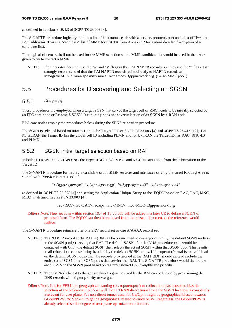
These procedures are employed when a target SGSN that serves the target cell or RNC needs to be initially selected by an EPC core node or Release-8 SGSN. It explicitly does not cover selection of an SGSN by a RAN node.
EPC core nodes employ the procedures below during the SRNS relocation procedure.
The SGSN is selected based on information in the Target ID (see 3GPP TS 23.003 [4] and 3GPP TS 25.413 [12]). For PS GERAN the Target ID has the global cell ID including PLMN and for U-TRAN the Target ID has RAC, RNC-ID and PLMN.
5.5.2 SGSN initial target selection based on RAI
In both U-TRAN and GERAN cases the target RAC, LAC, MNC, and MCC are available from the information in the Target ID.
The S-NAPTR procedure for finding a candidate set of SGSN services and interfaces serving the target Routing Area is started with "Service Parameters" of
"x-3gpp-sgsn:x-gn", "x-3gpp-sgsn:x-gp", "x-3gpp-sgsn:x-s3", "x-3gpp-sgsn:x-s4"
as defined in 3GPP TS 23.003 [4] and setting the Application-Unique String to the FQDN based on RAC, LAC, MNC, MCC as defined in 3GPP TS 23.003 [4]:
rac<RAC>.lac<LAC>.rac.epc.mnc<MNC>. mcc<MCC>.3gppnetwork.org
Editor's Note: New sections within section 19.4 of TS 23.003 will be added in a later CR to define a FQDN of proposed form. The FQDN can then be removed from the present document as the reference would suffice.
The S-NAPTR procedure returns either one SRV record set or one A/AAAA record set.
NOTE 1: The NAPTR record at the RAI FQDN can be provisioned to correspond to only the default SGSN node(s) in the SGSN pool(s) serving that RAI. The default SGSN after the DNS procedure exits would be contacted with GTP, the default SGSN then selects the actual SGSN within that SGSN pool. This results in all relocation requests being handled by the default SGSN nodes. If the operator's goal is to avoid load on the default SGSN nodes then the records provisioned at the RAI FQDN should instead include the entire set of SGSN in all SGSN pools that service that RAI. The S-NAPTR procedure would then return each SGSN in the SGSN pool based on the provisioned DNS weights and priority.
NOTE 2: The SGSN(s) closest to the geographical region covered by the RAI can be biased by provisioning the DNS records with higher priority or weights.
Editor's Note: It is for FFS if the geographical naming (i.e. topon/topoff) or collocation bias is used to bias the selection of the Release-8 SGSN as well. For UTRAN direct tunnel case the SGSN location is completely irrelevant for user plane. For non-direct tunnel case, for Gn/Gp it might be geographical biased towards GGSN/PGW, for S3/S4 it might be geographical biased towards SGW. Regardless, the GGSN/PGW is already selected so the degree of user plane optimization is limited.

ETSI
ETSI TS 129 303 V8.0.0 (2009-01) 173GPP TS 29.303 version 8.0.0 Release 8
NOTE 3: Service parameters are limited to those supported by the node doing the search.
For the case when a UE is moving from a pre-Release-8 UTRAN/GERAN to a Release-8 target SGSN the pre-Release-8 source node will not be able to use the .3ggpnetwork.org based records. As a result the target Release 8 SGSN (or MME) looks like a pre-Release 8 SGSN to a pre-Release-8 source node. For pre-Release 8 compatibility operators would continue to provision A/AAAA records as per Annex C.1 of 3GPP TS 23.003 [4] for the corresponding Gn/Gp interfaces regardless of whether the target SGSN is pre-Release-8 or not.
5.5.3 SGSN initial target selection based on RNC-ID (UTRAN target)
Editor's Note: The finer granularity this procedure allows only applies to UTRAN and only when different RNC-IDs have the same RAI values. It is for FFS if this procedure is worth the added complexity and provisioning required in comparison to the RAI based selection of the previous subsection which applies to UTRAN and GERAN.
This procedure is used only for a UTRAN target in the SRNS procedure.
In UTRAN case the target RNC-ID, MNC, and MCC are available from the information in the Target ID.
The S-NAPTR procedure for finding a candidate set of SGSN services and interfaces serving the target RNC is started with "Service Parameters" of
"x-3gpp-sgsn:x-gn", "x-3gpp-sgsn:x-gp", "x-3gpp-sgsn:x-s3", "x-3gpp-sgsn:x-s4"
as defined in 3GPP TS 23.003 [4] and setting the Application-Unique String to the RNC-ID FQDN based on RNC-ID,MNC,MCC as defined in 3GPP TS 23.003 [4]:
rnc<RNC-ID>.rnc.epc.mnc<MNC>.mcc<MCC>.3gppnetwork.org
Editor's Note: New sections within section 19.4 of TS 23.003 will be added in a later CR to define a FQDN of proposed form. The FQDN can then be removed from the present document as the reference would suffice.
The S-NAPTR procedure returns either one SRV record set or one A/AAAA record set.
NOTE 1: The NAPTR record at the RNC-ID FQDN can be provisioned to correspond to only the default SGSN node(s) in the SGSN pool(s) serving that RNC. The default SGSN after the DNS procedure exits would be contacted with GTP, the default SGSN then selects the actual SGSN within that SGSN pool. This results in all relocation requests being handled by the default SGSN nodes. If the operator's goal is to avoid load on the default SGSN nodes then the records provisioned at the RNC-ID FQDN should instead include the entire set of SGSN in all SGSN pools that service that RNC. The S-NAPTR procedure would then return each SGSN in the SGSN pool based on the provisioned DNS weights and priority.
NOTE 2: The SGSN(s) closest to the geographical region serving the RNC can be biased by provisioning the DNS records with higher priority or weights.
Editor's Note: It is for FFS if the geographical naming (i.e. topon/topoff) or collocation bias is used to bias the selection of the Release-8 SGSN. Conclusions should be the same as that for the RAI based SGSN selection.
NOTE 3: Service parameters are limited to those supported by the node doing the search.
For the case when a UE is moving from a pre-Release-8 UTRAN/GERAN to a Release-8 target SGSN the pre-Release-8 source node will not be able to use the .3ggpnetwork.org based records. As a result the target Release-8 SGSN (or MME) looks like a pre-Release-8 SGSN to a pre-Release-8 source node. For pre-Release 8 compatibility operators would continue to provision A/AAAA records as per Annex C.3 of 3GPP TS 23.003 [4] for the corresponding Gn/Gp interfaces regardless of whether the target SGSN is pre-Release-8 or not.

ETSI
ETSI TS 129 303 V8.0.0 (2009-01) 183GPP TS 29.303 version 8.0.0 Release 8
Annex A (Informative): Examples
Editor"s note: This annex will contain examples of various EPC node discovery and selection procedures.

ETSI
ETSI TS 129 303 V8.0.0 (2009-01) 193GPP TS 29.303 version 8.0.0 Release 8
Annex B (Normative): DNS procedures clarifications
B.1 DNS RFC procedures general clarifications This sub-clause clarifies DNS resolver use of the S-NAPTR procedures in EPC core network nodes.
NOTE: The only EPC core network nodes identified explicitly at this time that employ S-NAPTR procedures are the MME and Release 8 SGSN.
DNS resolvers in EPC core network nodes shall support recursive queries and responses over UDP transport as specified in IETF RFC 1035 [3]. The EPC core network nodes may assume the existence of a local caching DNS server (see GSMA PRD IR.67 [5]) and hence may not need to do iterative queries as specified in IETF RFC 1035 [3]. However, the final deployment decision of local caching DNS servers is up to the operators. It is recommended that the EPC core network nodes support DNS queries and responses over TCP transport up to the 65535 byte maximum. Support of IETF RFC 2671 [13] (EDNS0) is recommended, in order to allow DNS response packets sizes over 512 octets when using UDP transport.
It is recommended that resolvers in EPC core network nodes cache frequently used DNS queries in order to lower load on DNS infrastructure.
EPC core network nodes shall support SRV records as specified in IETF RFC 2782 [8]. However, in the 3GPP scope the ordering of SRV records of the same priority SHALL use the algorithm described in IETF RFC 2782 [8] page 4 instead of the the "SHOULD" requirement in the IETF RFC. This is a 3GPP specific requirement to strengthen the described algorithm and actually allow predictable behavior of the IETF RFC 2782 [8] based load balancing.
B.2 DNS procedures 3GPP clarifications on S-NAPTR IETF RFC 3958 [9] S-NAPTR procedures are unmodified with an exception of the following clarifications on the topological closeness and multi-protocol support:
1) For topological closeness the "topon" label matching of subclause 4.3.2 of the present document takes precedence over NAPTR ordering but NAPTR ordering is still used when matching label lengths are equal. Therefore, a full list of "candidate" records is needed as sketched in Appendix A.2 of IETF RFC 3958 [9], which in turn requires "backtracking" as described by IETF RFC 3958 [9] section 2.2.4.
2) IETF RFC 3958 [9] has an ambiguity for S-NAPTR with multiple protocols in last paragraph of section 2.2.5 "It MAY choose to run simultaneous DDDS resolutions for more than one protocol, in which case the requirements above apply for each protocol independently. That is, do not switch protocols mid- resolution." The term " simultaneous DDDS resolutions" and "apply for each protocol independently" are not defined and can have different meanings. To resolve that ambiguity in S-NAPTR, the present document formally defines "Service description meeting the client requirement" from IETF RFC 3402 [14] section 3.3 step 4 as a NAPTR record with one or more of the 3GPP desired service and protocol field pair(s) and such that all ancestor NAPTR records in the current path to this point also include the identified service and protocol in the DDDS procedure. The present document uses that as the definition of "simultaneous DDDS resolutions". See subclause C.1 for more practical information on this point.
Items 1) and 2) impact the ordering of DNS records and in which they are returned by the S-NAPTR procedure. Items 1) and 2) also involve areas where the IETF RFC 3958 [9] only provides a sketch of the procedures needed and implicitly relies on IETF RFC 3402 [14] for details. To clarify these points as well as to guide implementations informative pseudo-code is provided in subclauses C.1, C.2 and C.3.
ETSI
ETSI TS 129 303 V8.0.0 (2009-01) 203GPP TS 29.303 version 8.0.0 Release 8
Annex C (Informative): DNS Pseudo-Code
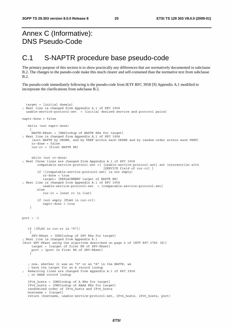
C.1 S-NAPTR procedure base pseudo-code The primary purpose of this section is to show practically any differences that are normatively documented in subclause B.2. The changes to the pseudo-code make this much clearer and self-contained than the normative text from subclause B.2.
The pseudo-code immediately following is the pseudo-code from IETF RFC 3958 [9] Appendix A.1 modified to incorporate the clarifications from subclause B.2.
target = [initial domain] ; Next line is changed from Appendix A.1 of RFC 3958 usable-service-protocol-set = [initial desired service and protocol pairs] naptr-done = false while (not naptr-done) { NAPTR-RRset = [DNSlookup of NAPTR RRs for target] ; Next line is changed from Appendix A.1 of RFC 3958 [sort NAPTR by ORDER, and by PREF within each ORDER and by random order within each PREF] rr-done = false cur-rr = [first NAPTR RR] while (not rr-done) ; Next three lines are changed from Appendix A.1 of RFC 3958 compatable-service-protocol-set =[ [usable-service-protocol-set] set intersection with [SERVICE field of cur-rr] ] if ([compatable-service-protocol-set] is not empty) rr-done = true target= [REPLACEMENT target of NAPTR RR] ; Next line is changed from Appendix A.1 of RFC 3958 usable-service-protocol-set = [compatable-service-protocol-set] else cur-rr = [next rr in list] if (not empty [FLAG in cur-rr]) naptr-done = true } port = -1 if ([FLAG in cur-rr is "S"]) { SRV-RRset = [DNSlookup of SRV RRs for target] ; Next line is changed from Appendix A.1 [Sort SRV RRset using the algorithm described on page 4 of IETF RFC 2782 [8]] target = [target of first RR of SRV-RRset] port = [port in first RR of SRV-RRset] } ; now, whether it was an "S" or an "A" in the NAPTR, we ; have the target for an A record lookup ; Remaining lines are changed from Appendix A.1 of RFC 3958 ; or AAAA record lookup IPv4_hosts = [DNSlookup of A RRs for target] IPv6_hosts = [DNSlookup of AAAA RRs for target] randomized order of IPv4_hosts and IPv6_hosts hostname = [target] return (hostname, usable-service-protocol-set, IPv4_hosts, IPv6_hosts, port)

ETSI
ETSI TS 129 303 V8.0.0 (2009-01) 213GPP TS 29.303 version 8.0.0 Release 8
The significant differences in the above Pseudo-Code and the IETF RFC 3958 [9] Pseudo-Code are :
A) [Sort SRV RRset using the algorithm described on page 4 of IETF RFC 2782 [8]] which was changed from [sort SRV-RRset based on PREF] The Pseudo-Code in IETF RFC 3958 [9] simply has an error. There isn't even a PREF in a SRV record. Again see page 4 of IETF RFC 2782 [8] for the proper procedure.
B) IETF RFC 3958 [9] Appendix A.1 starts with "Assuming the client supports 1 protocol for a particular application" so the pseudo-code obviously was designed for one protocol at a time. The lines with usable-service-protocol-set and compatable-service-protocol-set above are the most important change to support multiple service/protocol combinations and are really the primary reason for providing the above Pseudo-Code.
There are two possible ways to interpret the last paragraph of section 2.2.5 of IETF RFC 3958 [9] when a list of multiple services/protocols is desired. One is the above interpretation using "set intersection" which allows multiple services/protocols. The other is to run the above procedure for one service and protocol at a time from the "desired service_and_protocol_set" and get a separate list for each service and protocol. In both approaches the relative ordering within a particular service and protocol is identical. If the proper interpretation of IETF RFC 3958 [9] is one service and protocol at a time, then the IETF RFC 3958 [9] does not define order between different service or protocols. Thus 3GPP is free to order between different 3GPP service and protocol types so long as the order within a service and protocol is respected. The above method does respect the order within a service and protocol therefore it is valid in either interpretation of section 2.2.5 of IETF RFC 3958 [9] and also valid in IETF RFC 3402 [14]).
The remaining changes in Pseudo-Code above are minor and mostly intended to show that the S-NAPTR procedure logically outputs following:
(hostname, usable-service-protocol-set, IPv4_hosts, IPv6_hosts, port)
where the returned hostname is the FQDN of the topologically aware node name with topon/topoff and interface information.
In the 3GPP scope, a full implementation of RFC 3958 SHALL implement "backtracking" as described by IETF RFC 3958 [9] section 2.2.4 as required in subclause B.2.
For simplicity of the presentation in this Annex we assume a full IETF RFC 3958 [9] implementation with a call back interface as described in Appendix A.2 of the IETF RFC 3958 [9].
procedure S_NAPTR_to_callback(targetFQDN, desired_service_and_protocol_set, call_back_function)
where the call_back_function has interface
call_back_function (hostname, usable_service_and_protocol_set, port, IPv4_list,IP6_list)
The call_back_function returns "stop" if it does not want more records otherwise it returns "looking" and will be called with the next record.
C.2 S-NAPTR procedure - no topon If topological closeness is not used or all node names are prefixed with "topoff", then the first interface that can be successfully connected to would be sufficient to be returned from the S-NAPTR procedure.The following pseudo-code shows how the procedure works.
/* * The Callback function called from the S-NAPTR procedure * for each FQDN the S-NAPTR procedure finds.. */ procedure try_to_connect (hostname, service_and_protocol_set, port, IP4_list, IP6_list) Begin procedure // Comment does procedure as outlined in C.1 Use 3GPP procedures to try to connect in turn to all combinations
ETSI
ETSI TS 129 303 V8.0.0 (2009-01) 223GPP TS 29.303 version 8.0.0 Release 8
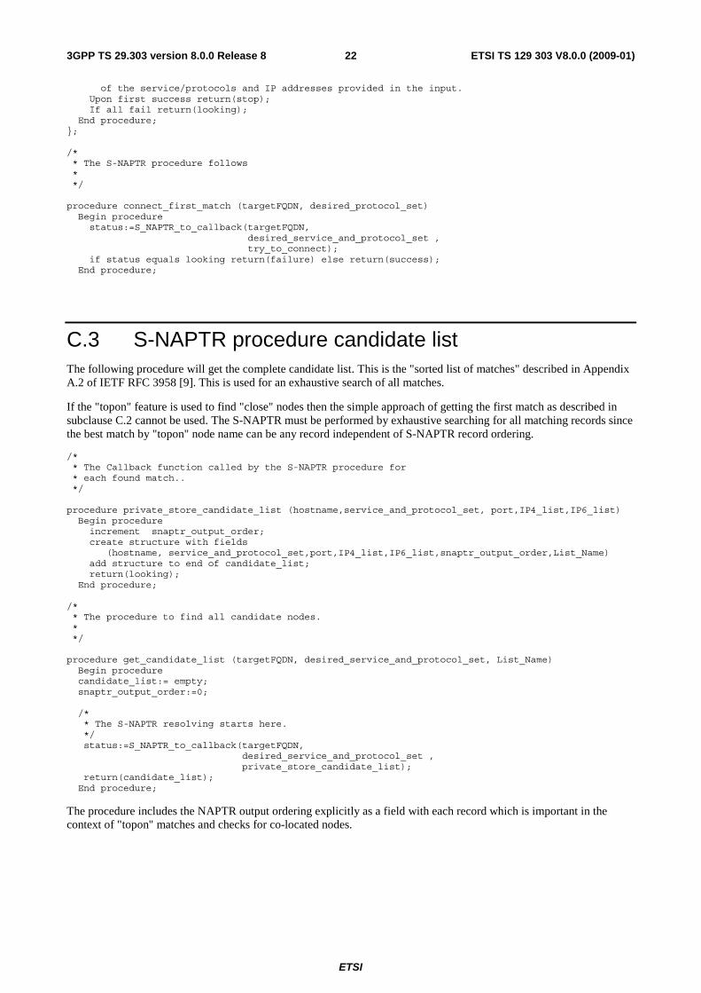
of the service/protocols and IP addresses provided in the input. Upon first success return(stop); If all fail return(looking); End procedure; }; /* * The S-NAPTR procedure follows * */ procedure connect_first_match (targetFQDN, desired_protocol_set) Begin procedure status:=S_NAPTR_to_callback(targetFQDN, desired_service_and_protocol_set , try_to_connect); if status equals looking return(failure) else return(success); End procedure;
C.3 S-NAPTR procedure candidate list The following procedure will get the complete candidate list. This is the "sorted list of matches" described in Appendix A.2 of IETF RFC 3958 [9]. This is used for an exhaustive search of all matches.
If the "topon" feature is used to find "close" nodes then the simple approach of getting the first match as described in subclause C.2 cannot be used. The S-NAPTR must be performed by exhaustive searching for all matching records since the best match by "topon" node name can be any record independent of S-NAPTR record ordering.
/* * The Callback function called by the S-NAPTR procedure for * each found match.. */ procedure private_store_candidate_list (hostname,service_and_protocol_set, port,IP4_list,IP6_list) Begin procedure increment snaptr_output_order; create structure with fields (hostname, service_and_protocol_set,port,IP4_list,IP6_list,snaptr_output_order,List_Name) add structure to end of candidate_list; return(looking); End procedure; /* * The procedure to find all candidate nodes. * */ procedure get_candidate_list (targetFQDN, desired_service_and_protocol_set, List_Name) Begin procedure candidate_list:= empty; snaptr_output_order:=0; /* * The S-NAPTR resolving starts here. */ status:=S_NAPTR_to_callback(targetFQDN, desired_service_and_protocol_set , private_store_candidate_list); return(candidate_list); End procedure;
The procedure includes the NAPTR output ordering explicitly as a field with each record which is important in the context of "topon" matches and checks for co-located nodes.

ETSI
ETSI TS 129 303 V8.0.0 (2009-01) 233GPP TS 29.303 version 8.0.0 Release 8
C.4 S-NAPTR procedure pseudo-code with topon Topological ordering takes precedence over S-NAPTR ordering. However, S-NAPTR ordering is used for ordering nodes with equivalent topological distances. Pseudo code below is informative and shows how to implement the ordering of record selection.
Assume two distinct types of nodes "A" and "B" are being checked for closeness and the best record pair is needed. First step, which is documented in each case in the main text of this document is to get two candidate lists using a procedure such as that outlined in subclause C.3.
candidate_list_A:= get_candidates (targetFQDN_A,desired_service_and_protocol_set_A, "A"); candidate_list_B:= get_candidates (targetFQDN_B,desired_service_and_protocol_set_B, "B");
As an example take the selection of a PGW and SGW by an MME during a UE initial attach procedure. Both a PGW and SGW need to be selected and if "topon" is used in both lists the selected pair is to be as close as possible (collocated being the closest).
Sometimes one list in the procedure is not found by DNS (or was found previously) because the node was already selected. In that case, one of the candidate lists can be just one node.
For example, an UE with an existing PDN connection adds a new PDN connection to a different APN, which may result in a different PGW but needs to continue using the current SGW. Here one of the two candidate lists would just be the data for the current SGW node (i.e., its node name and whether it supports GTPv2 and/or PMIPv6 for S5/S8).
procedure topo_matching (candidate_list_A,candidate_list_B) Begin procedure paired_sets_list:=empty; from number_labels_to_match:= maximum number_of_DNS labels down to 0 do Begin do if number_labels_to_match equals 0 then Begin if total_list:= candidate_list_A and candidate_list B else total_list:= get all records from candidate_list_A and candidate_list_ with "topon" as first label and hostname has at least (number_labels_to_match+2) labels // Comment: Add 2 since the first two labels are not part of the node name End If; // Comment: Below suffix is a hostname chopped off to include only the last number_labels_to_match Foreach unique suffix from total_list do Begin foreach Foreach servce and protocol do Begin foreach full_match_list:= get all records from total_list with service and protocol and suffix contained in end of the hostname If there is at least one "A" record and one "B" record in full_match_list then Begin If degree:=number_labels create structure with fields (degree, suffix,service_and_protocol,full_match_list) add that structure to paired_sets_list End If // do same for colocated nodes treating it as very high degree full_match_list:= get all records from total_list with service and protocol and suffix matching hostname excluding first two labels If there is at least one "A" record and one "B" record in full match_list then Begin If degree:=256 create structure with field (degree, suffix,service_and_protocol,full_match_list) add that structure to paired_sets_list End If End foreach End foreach End do sort paired_sets by degree return (paired_sets_list) End Procedure;

ETSI
ETSI TS 129 303 V8.0.0 (2009-01) 243GPP TS 29.303 version 8.0.0 Release 8
NOTE 1: Matching co-located nodes get a degree of 256, which is above any normal match. Also the above procedure is specific to this document and is not a part of S-NAPTR.
NOTE 2: Order from S-NAPTR is from one S-NAPTR procedure. There is no meaningful order obtained from S-NAPTR between records from two different S-NAPTR procedures. So one node type will be selected "logically first" based on other criteria outside S-NAPTR information.
The above procedure simply creates a list of records which are sorted by decreasing degree of matching in DNS labels. It also gives the list of paired nodes with the same suffix and compatible service which is needed by the 3GPP application.
Since highest degree is preferred over S-NAPTR ordering with "topon" labels the selection is done by degree starting with the highest degree obtaining only the possible "A" and "B" nodes at that degree. A sublist of the paired_sets_list containing the highest degree is taken from paired_sets_list denoted as degree_sublist. Assume the "A" node is to be selected "logically first". Sort the "A" parts of degree_sublist in increasing "snaptr_output_order". For the records in that order try to connect to the node with the service and protocol in the record using 3GPP procedures. On failure proceed with the next record. When that degree_sublist is exhausted then degree-1 is tried and so on until an "A" node is selected. Once an "A" node is chosen, the procedure has also a selected degree, suffix and service.
NOTE 3: The remaining part of this procedure is not needed if the "B" node was already pre-selected outside the present procedure.
Taking the degree_sublist used to select the "A" node create a new sublist from only records with the same service, same protocol and suffix. Remove the "A" node records from that sublist. Sort this new sublist by increasing "snaptr_output_order" (see subclause C.3). Using the records in that order try to connect to the "B" nodes with the service and protocol in the record. On a failure proceed with the next record. When that list is exhausted the procedure continues in next paragraph.
NOTE 4: The suffix of the "A" node that was selected influences which "B" nodes are closest to it. We can't easily and simply reuse the above structure for that reason and it is easier to "reset" the procedure..
A new candidate_list_A is created consisting only of the selected "A" node A and service_and_protocol. The procedure "topo_matching " is run again giving a new paired_sets_list. The "A" node records are removed from the new paired_sets_list leaving only "B" nodes. Sort the records in paired_sets_list in decreasing order of degree and within degree in increasing "snaptr_output_order" (see subclause C.3). Using the records in that order try to connect to the "B" nodes with the service in the record. On failure go to next record.
NOTE 5: Failing to actually contact a node should result in the failing node(s) to be removed from consideration for a period of time. Such removal is not detailed above. Also a reasonable implementation would give up after some maximum number of failed attempts.

ETSI
ETSI TS 129 303 V8.0.0 (2009-01) 253GPP TS 29.303 version 8.0.0 Release 8
Annex D (Informative): Change history
Change history Date TSG # TSG Doc. CR Rev Subject/Comment Old New 2008-12 CT#42 CP-080714 V2.0.0 approved in CT#42 2.0.0 8.0.0

ETSI
ETSI TS 129 303 V8.0.0 (2009-01) 263GPP TS 29.303 version 8.0.0 Release 8
History
Document history
V8.0.0 January 2009 Publication