TS 126 260 - V15.0.0 - 5G; Objective test methodologies ... · Audio is a key component of an...
24
ETSI TS 126 260 V15.0.0 (2018-10) 5G; Objective test methodologies for the evaluation of immersive audio systems (3GPP TS 26.260 version 15.0.0 Release 15) TECHNICAL SPECIFICATION
Transcript of TS 126 260 - V15.0.0 - 5G; Objective test methodologies ... · Audio is a key component of an...

ETSI TS 126 260 V15.0.0 (2018-10)
5G; Objective test methodologies for the evaluation of immersive
audio systems (3GPP TS 26.260 version 15.0.0 Release 15)
TECHNICAL SPECIFICATION

ETSI
ETSI TS 126 260 V15.0.0 (2018-10)13GPP TS 26.260 version 15.0.0 Release 15
Reference RTS/TSGS-0426260vf00
Keywords 5G
ETSI
650 Route des Lucioles F-06921 Sophia Antipolis Cedex - FRANCE
Tel.: +33 4 92 94 42 00 Fax: +33 4 93 65 47 16
Siret N° 348 623 562 00017 - NAF 742 C
Association à but non lucratif enregistrée à la Sous-Préfecture de Grasse (06) N° 7803/88
Important notice
The present document can be downloaded from: http://www.etsi.org/standards-search
The present document may be made available in electronic versions and/or in print. The content of any electronic and/or print versions of the present document shall not be modified without the prior written authorization of ETSI. In case of any
existing or perceived difference in contents between such versions and/or in print, the only prevailing document is the print of the Portable Document Format (PDF) version kept on a specific network drive within ETSI Secretariat.
Users of the present document should be aware that the document may be subject to revision or change of status. Information on the current status of this and other ETSI documents is available at
https://portal.etsi.org/TB/ETSIDeliverableStatus.aspx
If you find errors in the present document, please send your comment to one of the following services: https://portal.etsi.org/People/CommiteeSupportStaff.aspx
Copyright Notification
No part may be reproduced or utilized in any form or by any means, electronic or mechanical, including photocopying and microfilm except as authorized by written permission of ETSI.
The content of the PDF version shall not be modified without the written authorization of ETSI. The copyright and the foregoing restriction extend to reproduction in all media.
© ETSI 2018.
All rights reserved.
DECTTM, PLUGTESTSTM, UMTSTM and the ETSI logo are trademarks of ETSI registered for the benefit of its Members. 3GPPTM and LTETM are trademarks of ETSI registered for the benefit of its Members and
of the 3GPP Organizational Partners. oneM2M logo is protected for the benefit of its Members.
GSM® and the GSM logo are trademarks registered and owned by the GSM Association.

ETSI
ETSI TS 126 260 V15.0.0 (2018-10)23GPP TS 26.260 version 15.0.0 Release 15
Intellectual Property Rights Essential patents
IPRs essential or potentially essential to normative deliverables may have been declared to ETSI. The information pertaining to these essential IPRs, if any, is publicly available for ETSI members and non-members, and can be found in ETSI SR 000 314: "Intellectual Property Rights (IPRs); Essential, or potentially Essential, IPRs notified to ETSI in respect of ETSI standards", which is available from the ETSI Secretariat. Latest updates are available on the ETSI Web server (https://ipr.etsi.org/).
Pursuant to the ETSI IPR Policy, no investigation, including IPR searches, has been carried out by ETSI. No guarantee can be given as to the existence of other IPRs not referenced in ETSI SR 000 314 (or the updates on the ETSI Web server) which are, or may be, or may become, essential to the present document.
Trademarks
The present document may include trademarks and/or tradenames which are asserted and/or registered by their owners. ETSI claims no ownership of these except for any which are indicated as being the property of ETSI, and conveys no right to use or reproduce any trademark and/or tradename. Mention of those trademarks in the present document does not constitute an endorsement by ETSI of products, services or organizations associated with those trademarks.
Foreword This Technical Specification (TS) has been produced by ETSI 3rd Generation Partnership Project (3GPP).
The present document may refer to technical specifications or reports using their 3GPP identities, UMTS identities or GSM identities. These should be interpreted as being references to the corresponding ETSI deliverables.
The cross reference between GSM, UMTS, 3GPP and ETSI identities can be found under http://webapp.etsi.org/key/queryform.asp.
Modal verbs terminology In the present document "shall", "shall not", "should", "should not", "may", "need not", "will", "will not", "can" and "cannot" are to be interpreted as described in clause 3.2 of the ETSI Drafting Rules (Verbal forms for the expression of provisions).
"must" and "must not" are NOT allowed in ETSI deliverables except when used in direct citation.

ETSI
ETSI TS 126 260 V15.0.0 (2018-10)33GPP TS 26.260 version 15.0.0 Release 15
Contents Intellectual Property Rights ................................................................................................................................ 2
Foreword ............................................................................................................................................................. 2
Modal verbs terminology .................................................................................................................................... 2
Foreword ............................................................................................................................................................. 4
Introduction ........................................................................................................................................................ 4
1 Scope ........................................................................................................................................................ 5
2 References ................................................................................................................................................ 5
3 Definitions, symbols and abbreviations ................................................................................................... 5
3.1 Definitions .......................................................................................................................................................... 5
3.2 Symbols .............................................................................................................................................................. 5
3.3 Abbreviations ..................................................................................................................................................... 6
4 Objective Test Methodologies for Immersive Audio Systems ................................................................. 6
4.1 Objective Test Methodologies for Assessment of Immersive Audio Systems in the Sending Direction ........... 6
4.1.1 Diffuse-field Send Frequency Response for Scene-based Audio ................................................................. 6
4.1.1.1 Introduction ............................................................................................................................................. 6
4.1.1.2 Definition ................................................................................................................................................ 6
4.1.1.3 Test method with periphonic array .......................................................................................................... 7
4.1.1.3.1 Test Conditions .................................................................................................................................. 7
4.1.1.3.2 Measurement ..................................................................................................................................... 8
4.1.1.4 Test method with loudspeaker array and turn table ................................................................................. 9
4.1.1.4.1 Test Conditions .................................................................................................................................. 9
4.1.1.4.2 Measurement ..................................................................................................................................... 9
4.1.2 Directional response measurement for scene-based audio .......................................................................... 10
4.1.2.1 Definition .............................................................................................................................................. 10
4.1.2.2 Test conditions ...................................................................................................................................... 10
4.1.2.3 Measurement ......................................................................................................................................... 10
4.2 Objective Test Methodologies for Assessment of Immersive Audio Systems in the Receiving Direction ...... 10
4.2.1 Headset Binaural Diffuse-field Receive frequency response for Scene-based audio ................................. 10
4.2.1.1 Introduction ........................................................................................................................................... 10
4.2.1.2 Definition .............................................................................................................................................. 10
4.2.1.3 Test Conditions ..................................................................................................................................... 11
4.2.1.4 Measurement ......................................................................................................................................... 11
4.2.2 Nominal System Sensitivity in Receive Direction for Channel-based audio .............................................. 11
4.2.2.1 Introduction ........................................................................................................................................... 11
4.2.2.2 Definition .............................................................................................................................................. 12
4.2.2.3 Test Conditions ..................................................................................................................................... 12
4.2.2.4 Measurement ......................................................................................................................................... 12
4.2.3 Motion to Sound Latency in Dynamic Binaural Rendering Systems ......................................................... 12
4.2.3.1 Introduction ........................................................................................................................................... 12
4.2.3.2 Requirements ........................................................................................................................................ 12
4.2.3.3 Calibration ............................................................................................................................................. 14
4.2.3.4 Evaluation Environment ........................................................................................................................ 14
4.2.3.5 Data acquisition ..................................................................................................................................... 14
4.2.3.6 Data Analysis ........................................................................................................................................ 14
Annex A (normative): Order dependent directions .......................................................................... 17
Annex B (informative): Change history ............................................................................................... 22
History .............................................................................................................................................................. 23
ETSI
ETSI TS 126 260 V15.0.0 (2018-10)43GPP TS 26.260 version 15.0.0 Release 15
Foreword This Technical Specification has been produced by the 3rd Generation Partnership Project (3GPP).
The contents of the present document are subject to continuing work within the TSG and may change following formal TSG approval. Should the TSG modify the contents of the present document, it will be re-released by the TSG with an identifying change of release date and an increase in version number as follows:
Version x.y.z
where:
x the first digit:
1 presented to TSG for information;
2 presented to TSG for approval;
3 or greater indicates TSG approved document under change control.
y the second digit is incremented for all changes of substance, i.e. technical enhancements, corrections, updates, etc.
z the third digit is incremented when editorial only changes have been incorporated in the document.
Introduction Audio is a key component of an immersive multimedia experience and 3GPP systems are expected to deliver immersive audio with a high Quality of Experience. However, industry agreed methods to assess the Quality of Experience for immersive audio are relatively few and the present document seeks to address this gap by providing objective test methods for the assessment of immersive audio.

ETSI
ETSI TS 126 260 V15.0.0 (2018-10)53GPP TS 26.260 version 15.0.0 Release 15
1 Scope The present document specifies objective test methodologies for 3GPP immersive audio systems including channel based, object based, scene-based and hybrids of these formats. The subjective evaluation methods described in the present document are applicable to audio capture, coding, transmission and rendering as indicated in their corresponding clauses.
2 References The following documents contain provisions which, through reference in this text, constitute provisions of the present document.
- References are either specific (identified by date of publication, edition number, version number, etc.) or non-specific.
- For a specific reference, subsequent revisions do not apply.
- For a non-specific reference, the latest version applies. In the case of a reference to a 3GPP document (including a GSM document), a non-specific reference implicitly refers to the latest version of that document in the same Release as the present document.
[1] 3GPP TR 21.905: "Vocabulary for 3GPP Specifications".
[2] J. Fliege und U. Maier: "A two-stage approach for computing cubature formulae for the sphere," Dortmund University, 1999.
[3] ISO 3745 - Annex A: "Acoustics - Determination of sound power levels and sound energy levels of noise sources using sound pressure -- Precision methods for anechoic rooms and hemi-anechoic rooms - Annex A: General procedures for qualification of anechoic and hemi-anechoic rooms".
[4] ISO 1996 Acoustics: "Description, measurement and assessment of environmental noise".
[5] ANSI S1.4: "Specifications for Sound Level Meters".
[6] ISO 3: "Preferred numbers – Series of preferred numbers".
3 Definitions, symbols and abbreviations
3.1 Definitions For the purposes of the present document, the terms and definitions given in 3GPP TR 21.905 [1] and the following apply. A term defined in the present document takes precedence over the definition of the same term, if any, in 3GPP TR 21.905 [1].
example: text used to clarify abstract rules by applying them literally.
3.2 Symbols For the purposes of the present document, the following symbols apply:
LAeq the sound level in decibels equivalent to the total A-weighted sound energy measured over a stated period of time.

ETSI
ETSI TS 126 260 V15.0.0 (2018-10)63GPP TS 26.260 version 15.0.0 Release 15
3.3 Abbreviations For the purposes of the present document, the abbreviations given in 3GPP TR 21.905 [1] and the following apply. An abbreviation defined in the present document takes precedence over the definition of the same abbreviation, if any, in 3GPP TR 21.905 [1].
4 Objective Test Methodologies for Immersive Audio Systems
4.1 Objective Test Methodologies for Assessment of Immersive Audio Systems in the Sending Direction
4.1.1 Diffuse-field Send Frequency Response for Scene-based Audio
4.1.1.1 Introduction
This test is applicable to UEs capturing scene-based audio (e.g. First and Higher Order Ambisonics).
NOTE: Currently, the test method uses a periphonic loudspeaker array for generation of a diffuse-field. Additional loudspeaker setups for the derivation of the diffuse sound field are under consideration.
General test conditions
Free-field propagation conditions
- The test environment shall contain a free-field volume, wherein free-field sound propagation conditions shall be observed.
- The free-field sound propagation conditions shall be observed down to a frequency of 200 Hz or less.
- Qualification of the free-field volume shall be performed using the method and limits for deviation from ideal free-field conditions described in [3].
Test environment noise floor
Within the free-field volume, the equivalent continuous sound level of the test environment in each 1/3rd octave band, Leq(f), shall be less than the limits of the NR10 curve, following the noise rating determination procedures in [4].
4.1.1.2 Definition
The Diffuse-field Send Frequency Response for Scene-based Audio is defined as the transfer function, ����, between:
�����, the estimated sound pressure magnitude spectrum obtained from a diffuse-field scene-based audio capture and reference synthesis at the geometric center of a free-field volume; and
�)����, the sound pressure magnitude spectrum obtained from a diffuse-field microphone recording the same diffuse field at the origin of a spherical coordinate system.
Figure 1 describes a typical block diagram for the scene-based audio sending direction with measurement points when using a periphonic loudspeaker array.

ETSI
ETSI TS 126 260 V15.0.0 (2018-10)73GPP TS 26.260 version 15.0.0 Release 15
Figure 1: Scene-based audio capture block diagram for sending direction measurements
Definition of Equivalent Spatial Domain
The equivalent spatial domain representation, w(t), of a Nth order Ambisonics soundfield representation c(t) is obtained by rendering c(t) to K virtual loudspeaker signals wj (t), 1 ≤ j ≤ K, with K = (N+1)2. The respective virtual loudspeaker positions are expressed by means of a spherical coordinate system, where each position lies on the unit sphere, i.e., a radius of 1. Hence, the positions can be equivalently expressed by order-dependent directions Ωj
(N)=(θj(N), φ j
(N)), 1 ≤ j ≤ K, where θj
(N) and φ j(N) denote the inclinations and azimuths, respectively. These directions are defined according to [2]
and reproduced in Annex B for convenience.
The rendering of ���� into the equivalent spatial domain can be formulated as a matrix multiplication:
w(t) = (Ψ(N,N))-1 ⋅c(t),
where �⋅���(⋅)-1 denotes the inversion.
The matrix Ψ(N,N) of order N with respect to the order-dependent directions Ωj(N) is defined by:
Ψ(N,N) := [S1(N) S2
(N) … SK(N)],
with:
�j(N) := [S0
0(Ωj(N)) S-1
-1(Ωj(N)) S-1
0(Ωj(N)) S-1
1(Ωj(N)) S-1
1(Ωj(N)) … SN
N(Ωj(N))]T ,
where Snm(⋅) represents the real valued spherical harmonics of the order n and degree m.
The matrix Ψ(N,N) is invertible so that the HOA representation ����c(t) can be converted back from the equivalent spatial domain by:
c(t) = Ψ(N,N)·w(t)
4.1.1.3 Test method with periphonic array
4.1.1.3.1 Test Conditions
Periphonic loudspeaker array
a) A periphonic loudspeaker array shall be placed within the free-field volume with the geometric center of the periphonic loudspeaker array coinciding with the geometric center of the free-field volume.
b) The periphonic loudspeaker array shall have a radius greater or equal than 1 meter.
ETSI
ETSI TS 126 260 V15.0.0 (2018-10)83GPP TS 26.260 version 15.0.0 Release 15
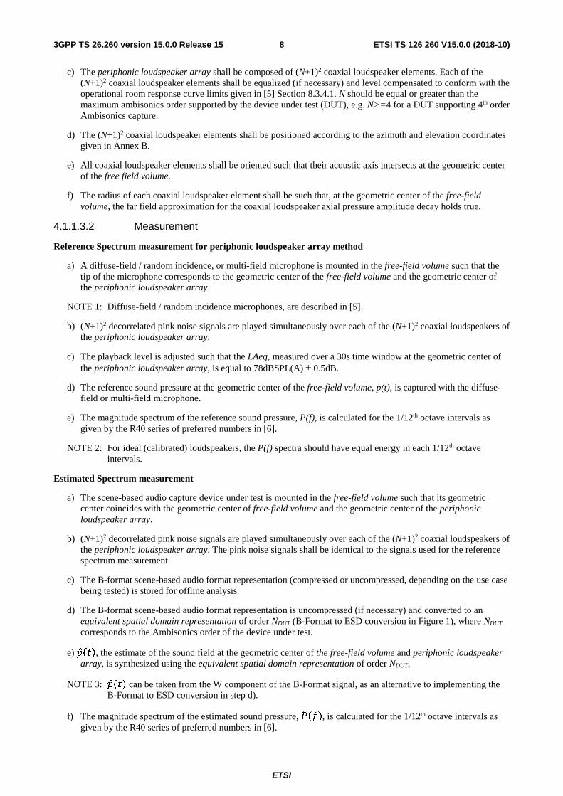
c) The periphonic loudspeaker array shall be composed of (N+1)2 coaxial loudspeaker elements. Each of the (N+1)2 coaxial loudspeaker elements shall be equalized (if necessary) and level compensated to conform with the operational room response curve limits given in [5] Section 8.3.4.1. N should be equal or greater than the maximum ambisonics order supported by the device under test (DUT), e.g. N>=4 for a DUT supporting 4th order Ambisonics capture.
d) The (N+1)2 coaxial loudspeaker elements shall be positioned according to the azimuth and elevation coordinates given in Annex B.
e) All coaxial loudspeaker elements shall be oriented such that their acoustic axis intersects at the geometric center of the free field volume.
f) The radius of each coaxial loudspeaker element shall be such that, at the geometric center of the free-field volume, the far field approximation for the coaxial loudspeaker axial pressure amplitude decay holds true.
4.1.1.3.2 Measurement
Reference Spectrum measurement for periphonic loudspeaker array method
a) A diffuse-field / random incidence, or multi-field microphone is mounted in the free-field volume such that the tip of the microphone corresponds to the geometric center of the free-field volume and the geometric center of the periphonic loudspeaker array.
NOTE 1: Diffuse-field / random incidence microphones, are described in [5].
b) (N+1)2 decorrelated pink noise signals are played simultaneously over each of the (N+1)2 coaxial loudspeakers of the periphonic loudspeaker array.
c) The playback level is adjusted such that the LAeq, measured over a 30s time window at the geometric center of the periphonic loudspeaker array, is equal to 78dBSPL(A) ± 0.5dB.
d) The reference sound pressure at the geometric center of the free-field volume, p(t), is captured with the diffuse-field or multi-field microphone.
e) The magnitude spectrum of the reference sound pressure, P(f), is calculated for the 1/12th octave intervals as given by the R40 series of preferred numbers in [6].
NOTE 2: For ideal (calibrated) loudspeakers, the P(f) spectra should have equal energy in each 1/12th octave intervals.
Estimated Spectrum measurement
a) The scene-based audio capture device under test is mounted in the free-field volume such that its geometric center coincides with the geometric center of free-field volume and the geometric center of the periphonic loudspeaker array.
b) (N+1)2 decorrelated pink noise signals are played simultaneously over each of the (N+1)2 coaxial loudspeakers of the periphonic loudspeaker array. The pink noise signals shall be identical to the signals used for the reference spectrum measurement.
c) The B-format scene-based audio format representation (compressed or uncompressed, depending on the use case being tested) is stored for offline analysis.
d) The B-format scene-based audio format representation is uncompressed (if necessary) and converted to an equivalent spatial domain representation of order NDUT (B-Format to ESD conversion in Figure 1), where NDUT corresponds to the Ambisonics order of the device under test.
e) �̂��, the estimate of the sound field at the geometric center of the free-field volume and periphonic loudspeaker array, is synthesized using the equivalent spatial domain representation of order NDUT.
NOTE 3: �̂�� can be taken from the W component of the B-Format signal, as an alternative to implementing the B-Format to ESD conversion in step d).
f) The magnitude spectrum of the estimated sound pressure, �����, is calculated for the 1/12th octave intervals as given by the R40 series of preferred numbers in [6].

ETSI
ETSI TS 126 260 V15.0.0 (2018-10)93GPP TS 26.260 version 15.0.0 Release 15
Calculation of send frequency response for scene-based audio
The send frequency response for scene-based audio, G(f), is calculated as ���� =�����
����.
4.1.1.4 Test method with loudspeaker array and turn table
4.1.1.4.1 Test Conditions
Loudspeaker array
a) A calibrated loudspeaker array shall be placed within the free-field volume.
b) The loudspeaker array shall comprise one or several semi-arcs having a radius greater or equal than 1 meter.
c) The loudspeaker array shall be composed of N+1 loudspeaker elements.
d) Each loudspeaker in the array shall be calibrated with a frequency response of [at least 100 Hz-20,000 Hz] and minimum phase response.
e) The coordinates of the loudspeaker elements are defined according to a Gaussian spherical grid of order N.
Turn table
a) A turn table with a resolution of [0.5°] shall be used. The rotation axis of the turn table and the vertical axis of the semi-arcs shall be aligned The turn table shall be adjusted in height so that the device under test is positioned at the geometric center of the loudspeaker array.
b) For measurement, an azimuth step of 180/(N+1) degrees shall be used.
4.1.1.4.2 Measurement
Reference Spectrum measurement
a) A diffuse-field / random incidence, or multi-field microphone is mounted in the free-field volume such that the tip of the microphone corresponds to the geometric center of the free-field volume and the geometric center of the loudspeaker array.
NOTE 1: Diffuse-field / random incidence microphones, are described in [5].
Repeat steps b-c) with an azimuth angular resolution of 180/(N+1) degrees:
b) An exponential sweep sine signal is played over each of the N+1 loudspeakers of the loudspeaker array.
c) The impulse response at the geometric center of the loudspeaker array is measured for each loudspeaker position.
d) The magnitude spectrum of the reference sound pressure, P(f), is calculated for the 1/12th octave intervals as given by the R40 series of preferred numbers in [6].
NOTE 2: For ideal (calibrated) loudspeakers, the P(f) spectra should have equal energy in each 1/12th octave intervals.
Estimated Spectrum measurement
a) The scene-based audio capture device under test is mounted in the free-field volume such that its geometric center coincides with the geometric center of free-field volume and the geometric center of the loudspeaker array.
b) Repeat steps b-c) with an azimuth angular resolution of 180/(N+1) degrees::
c) An exponential sweep sine signal is played over each of the N+1 loudspeakers of the loudspeaker array. The sweep signals shall be identical to the signals used for the reference spectrum measurement.
d) The impulse response at the geometric center of the loudspeaker array is measured for each loudspeaker position.

ETSI
ETSI TS 126 260 V15.0.0 (2018-10)103GPP TS 26.260 version 15.0.0 Release 15
e) The magnitude spectrum of the estimated sound pressure, �����, is calculated for the 1/12th octave intervals as given by the R40 series of preferred numbers in [6].
Calculation of send frequency response for scene-based audio
The send frequency response for scene-based audio, G(f), is calculated as ���� =�����
����.
4.1.2 Directional response measurement for scene-based audio
4.1.2.1 Definition
The directional response for scene-based audio is defined as the transfer function, represented as an impulse response, h(θi, φi), between a device under test and a loudspeaker located at an equal distance r and L predefined directions, (θi, φi), i=1,...,L.
4.1.2.2 Test conditions
Free-field propagation conditions
- The test environment shall contain a free-field volume, wherein free-field sound propagation conditions shall be observed.
- The free-field sound propagation conditions shall be observed down to a frequency of 200Hz.
Test environment noise floor
The equivalent continuous sound level of the test environment in each 1/3rd octave band, Leq(f), shall be less than the limits of the NR10 curve, following the noise rating determination procedures in [4].
Loudspeaker array
A real or simulated loudspeaker array comprising L loudspeakers located be a set of predefined directions (θi, φi), i=1,...,L, from the geometric center of the loudspeaker array shall be used.
4.1.2.3 Measurement
For each loudspeaker position (θi, φi), i=1,...,L , the following procedure shall be used:
a) An exponential sweep sine test signal is played over the loudspeaker.
NOTE: The impact of codec on the exponential sweep sine test signal needs to be verified before performing the measurements. An activation signal may be needed.
b) The impulse response h(θi, φi) at the geometric center of the loudspeaker array is measured.
4.2 Objective Test Methodologies for Assessment of Immersive Audio Systems in the Receiving Direction
4.2.1 Headset Binaural Diffuse-field Receive frequency response for Scene-based audio
4.2.1.1 Introduction
This test is applicable to UEs rendering scene-based audio (e.g. First and Higher Order Ambisonics) over a binaural headset.
4.2.1.2 Definition
The Headset Binaural Diffuse-field Receive Frequency Response for Scene-based Audio (for left and right ears) is defined as the transfer function, GL,R (f), between:

ETSI
ETSI TS 126 260 V15.0.0 (2018-10)113GPP TS 26.260 version 15.0.0 Release 15
a) PL,R(f), the binaurally recorded sound pressure magnitude spectra, obtained when a diffuse field signal in the equivalent spatial domain representation, w(t), is played on the DUT; and
b) Pref L,R(f), the reference sound pressure magnitude spectra, obtained by direct convolution of the diffuse field signal in the equivalent spatial domain representation, w(t) with its corresponding set of HRTFs.
4.2.1.3 Test Conditions
Test environment noise floor
The equivalent continuous sound level of the test environment in each 1/3rd octave band, Leq(f), shall be less than the limits of the NR10 curve, following the noise rating determination procedures in [4].
The set of HRTFs used by the UE shall be documented and available to the test lab.
4.2.1.4 Measurement
Reference sound pressure magnitude spectra
The reference sound pressure magnitude spectra are derived offline. The reference sound pressure magnitude spectra for the left and right ears, Pref L,R (f) is the frequency domain representation of the convolution between the set of equivalent spatial domain signals, w(t), with its corresponding set head related transfer functions h L,R(t), for each direction j in an equivalent spatial domain of order NDUT , i.e.:
��� ,���� = ℱ( ���� ∗ ℎ� ,�(�))
( �����)�
���
The signals wj(t), for 1 ≤ j ≤ (NDUT +1)2, are uncorrelated pink noise signals of 30s length.
Binaurally recorded sound pressure magnitude spectra
The binaurally recorded sound pressure magnitude spectra is obtained as follows:
a) The binaural headset is placed on a HATS.
b) The DUT shall be configured such that the set of HRTFs used for binaural rendering correspond to the HATS used for testing.
c) The DUT volume control (if any) is adjusted for its nominal setting.
d) The binaural time-domain signals are recorded with HATS.
e) The binaurally recorded sound pressure magnitude spectra, PL,R(f) is obtained by taking the Fourier transform of the binaurally recorded time-domain signals.
Calculation of headset binaural diffuse-field receive frequency response for scene-based audio
The headset binaural diffuse-field frequency response for scene-based audio, G(f), is calculated for each supported Ambisonics order NDUT as:
���� =�,� (�)
��� ,� (�)
4.2.2 Nominal System Sensitivity in Receive Direction for Channel-based audio
4.2.2.1 Introduction
This test is applicable to UEs rendering channel-based audio (e.g. 7.1.4) over a binaural headset.

ETSI
ETSI TS 126 260 V15.0.0 (2018-10)123GPP TS 26.260 version 15.0.0 Release 15
4.2.2.2 Definition
The nominal system sensitivity in receive direction for channel-based audio is defined as the ratio between the sound pressure level (in dBSPL(A)) produced by the DUT on HATS and the root mean square of the digital test signal (in dBFS).
4.2.2.3 Test Conditions
Test environment noise floor
The equivalent continuous sound level of the test environment in each 1/3rd octave band, Leq(f), shall be less than the limits of the NR10 curve, following the noise rating determination procedures in [4].
The specific HATS used for the recording shall be described in the test report. The set of HRTFs used by the UE shall be documented and available to the test lab.
4.2.2.4 Measurement
For each audio channel supported by the DUT, a pink noise signal with -18 dBFS RMS level is played, with the signals played only one channel at a time.
The LAeq (in dBSPL(A)) is measured continuously for a period of 30 s for each of the left and right ears.
The sensitivity Gi L,R is expressed as the ratio of the recorded sound pressure levels at the left and right ears and the root mean square digital level of the pink noise test signal, i.e. -18 dBFS.
�� ,� = ��� − 18
4.2.3 Motion to Sound Latency in Dynamic Binaural Rendering Systems
4.2.3.1 Introduction
Motion to Sound latency is the time difference between the event of a change in head rotation and when the immersive audio signal is finally compensated for the head motion. The method in this specification is intended to verify that the overall motion-to-sound latency that a user experiences upon rotating their head is within acceptable limits.
The method allows full measurement of motion to sound, i.e. including both the latency of the head tracking sensor as well as the audio playback. This includes all components of a real setup and therefore contains all possible causes of additional latency that a user may experience.
The method also provides a latency value for the isolated audio processing of the binaural renderer without the aforementioned external hardware, assuming that the binaural renderer can process audio data as an audio processing plugin that can be evaluated in isolation.
NOTE: This method requires synchronized playback of two renderer instances and may not be suitable for the measurements of UEs where such synchronization is not possible.
4.2.3.2 Requirements
The following will be required:
Software:
- Audio processing software to run and record output of two renderers simultaneously
- Head tracker software
Hardware:
- Host machine for audio processing
- Head tracker hardware
- Stereo audio recording interface
- Stereo audio playback interface

ETSI
ETSI TS 126 260 V15.0.0 (2018-10)133GPP TS 26.260 version 15.0.0 Release 15
- Mechanical setup to rotate the head tracking sensor in a precise and reproducible way
An exemplary hardware setup can be seen below in Figure 2, the method however can also be implemented using different systems under test and accompanying equipment:
Figure 2: Hardware Overview (Setup in Position 1 on the left, Position 2 on the right)
The audio processing environment uses two parallel signal chains, each containing its own instance of the same binaural renderer being tested. The test is concerned only with yaw angles, so values of pitch and roll should be set to zero at the beginning of the test and can be ignored thereafter.
Figure 3: Generic Audio Processing Environment
The initial conditions are that Rendering Chain 1 (RC1) has a static yaw head rotation angle of 0 degrees and RC2 uses the physical rotation of the head tracker to get its yaw value. A white noise signal is virtually placed directly in front of the listener (0 degrees azimuth, elevation), meaning that rotation of the arm directly affects how the white noise source is rendered.

ETSI
ETSI TS 126 260 V15.0.0 (2018-10)143GPP TS 26.260 version 15.0.0 Release 15
4.2.3.3 Calibration
The first step is to calibrate the final position of the rotating arm (Position 2 / P2). The rotating arm is moved manually and requires only a limited range of motion - from some small rotation away from the table (Position 1 / P1), 20 to 30 degrees will be ample, through until contact with the table (P2). The arm should be placed at P2 and set up so that this position also corresponds to 0 degrees yaw.
4.2.3.4 Evaluation Environment
An object within the evaluation environment, e.g. using Max/MSP, should be created to set the value of yaw to exactly 0 degrees once the real value of yaw (received from the head tracker) is <0.2 degrees.
NOTE: This tolerance value was chosen to be as small as possible while ensuring that it does not bounce (dependent on the accuracy of the tracking system)
This object should be designed to latch to zero once the actual value is under the tolerance threshold, so that any small accidental rebound of the rotating arm does not affect the yaw angle fed to the renderer - it artificially remains at exactly 0, which is important to ensure that both rendering chains have exactly the same head rotation when the arm is in its final position (P2). The output from the evaluation environment is captured by the recording audio interface, which therefore includes any latency introduced by playback.
4.2.3.5 Data acquisition
A test run begins by starting to record on the recording audio interface. The rotating arm is set to Position 1, then the audio processing set running and starts feeding the input source to both renderer instances. A microphone is positioned near the contact point at the table. This mono room microphone will be recorded synchronously with the output from the evaluation environment, with its purpose being to log the point of contact of the arm with the table, which should be done with a good amount speed and vigour so that the microphone picks up a loud knock at the table. Shortly after this (one or two seconds for example), with the test run now complete, playback and recording can be stopped.
Some milliseconds after the collision, the latest yaw value detected by the tracking system will have been passed into the evaluation environment (tTracking). With the target yaw value now reached (latched to zero in Max), both rendering chains will have the identical values of head rotation and therefore, after some further short delay, the output of both renderer instances will be identical.
4.2.3.6 Data Analysis
The overall motion-to-sound latency (tM2S) is taken as the time from the moment of collision until the point at which the two output signals are identical.
To easily visually inspect when this point occurs, one output channel of one signal chain (e.g. RC1-left) is subtracted from the same output channel of the complementary signal chain (RC2-left).
NOTE 1: This could be done manually in audio editor software after processing, but this would require recording at least three channels synchronously (one from each renderer chain, and one of the room microphone). Instead, the subtraction of signals can be done within Max/MSP, meaning only the output of this operation (one channel) and the room microphone can conveniently be recorded with a stereo audio interface. In addition to the stereo WAVE file recorded by a separate audio application, the Max/MSP application also writes to a separate mono WAVE file once it detects that it is in the final tolerated yaw position (latched on). This mono WAVE contains only the subtracted signals as described above, from which the tMspProc time can also be measured.
Evaluation is performed offline in audio editor software. The tMspProc time is measured from the start of the file until the point at which consecutive zero samples begin. This value encompasses any motion-to-sound latency caused by the tested renderer chain as well as any other latency caused by Virtual Studio Technology (VST) plugin framework buffering. The tMspProc time shall be measured from the audio frame boundary at which the latched-on yaw value is activated and applied within that audio frame.
NOTE 2: Since the yaw rotation update rate of the tracker is typically in the range of a few milliseconds, there is a framing mismatch when compared to the audio framing, but this mismatch will not be incorporated in the tMspProc value but rather only in the tM2S measurement.

ETSI
ETSI TS 126 260 V15.0.0 (2018-10)153GPP TS 26.260 version 15.0.0 Release 15
An example measurement of the tMspProc is displayed in Figure 4. For tM2S this is measured by selecting the duration between the visible collision peak in the microphone channel and the point at which the other channel reduces to silence. Figure 5 shows an example measurement for the motion-to-sound latency.
Figure 4: tMspProc latency measurement

ETSI
ETSI TS 126 260 V15.0.0 (2018-10)163GPP TS 26.260 version 15.0.0 Release 15
Figure 5: Motion-to-sound (tM2S) latency measurement
In Figure 5 the room recording is on the top, subtracted renderer output is on the bottom. Marked region is the time passed since the arm hits the table (recorded knock) and when the subtracted binaural renderer output reaches silence.
NOTE 3: Unlike the tMspProc measurement, the tM2S measurement is taken from signals recorded from hardware audio interfaces, hence it is not possible to look for continuous silence since the resulting file will always contain some noise added by the digital-to-analog and analog-to-digital converters. For this reason, it is important to ensure a high signal-to-noise ratio in the signal provided to audio interfaces, to make it easier to inspect where the cancellation occurs.

ETSI
ETSI TS 126 260 V15.0.0 (2018-10)173GPP TS 26.260 version 15.0.0 Release 15
Annex A (normative): Order dependent directions The following tables order-dependent directions �
( )= (��( )
,��
( )), 1 ≤ � ≤ �, where ��( ) and ��
( ) denote the inclinations and azimuths in radians, respectively.

ETSI
ETSI TS 126 260 V15.0.0 (2018-10)183GPP TS 26.260 version 15.0.0 Release 15
Index � ��(���) ��
(���)
1 0 0
2 1.910633 0 3 1.910633 2.094395
4 1.910633 -2.0944
Index � ��(���) ��
(���)
1 0 0
2 2.361073 0
3 1.207589 -1.95668 4 1.207589 1.956682
5 2.415178 -1.95668
6 1.561039 -3.14159
7 2.415178 1.956681 8 1.325668 0.687124
9 1.325667 -0.68712
Index � ��(���) ��
(���)
1 0 0 2 0.854098 0 3 2.031969 1.119907 4 2.605106 -0.25283 5 1.078622 1.155586 6 1.736608 2.040481 7 2.031968 -1.38118 8 1.736609 0.270692 9 1.56888 -2.20417
10 0.917087 2.297267 11 0.917087 -2.80293 12 1.763476 3.010956 13 2.649852 2.154919 14 1.568881 -0.63529 15 0.953962 -1.41973 16 2.458122 -2.46809

ETSI
ETSI TS 126 260 V15.0.0 (2018-10)193GPP TS 26.260 version 15.0.0 Release 15
Index � ��(���) ��
(���)
1 0 0 2 0.823218 0 3 1.73912 -2.00759 4 0.724297 1.927637 5 1.336281 -1.41208 6 0.871631 -2.10001 7 1.263705 2.512927 8 1.440147 1.667633 9 2.248313 1.442383
10 1.433953 -0.60062 11 2.888065 0.329968 12 2.003914 -1.18621 13 1.80266 2.983332 14 1.396554 -2.69222 15 2.170781 0.507602 16 1.952805 2.208977 17 1.58019 0.952319 18 2.584609 -1.71565 19 0.874597 0.934402 20 2.172935 -0.38654 21 2.612717 2.675958 22 2.193907 -2.62842 23 1.51674 0.165012 24 0.715307 -1.02504 25 0.762553 -3.13121

ETSI
ETSI TS 126 260 V15.0.0 (2018-10)203GPP TS 26.260 version 15.0.0 Release 15
Index � ��(���) ��
(���)
1 0 0 2 2.024896 0 3 1.247057 -1.19666 4 2.746177 0.184066 5 0.623575 0.124282 6 1.764494 -2.84022 7 1.070515 -1.84701 8 2.234325 0.698758 9 2.184128 2.280239 10 2.158839 -2.28482 11 0.624151 -2.37569 12 1.237485 2.883411 13 0.603422 -1.18504 14 1.133942 -2.76846 15 1.060655 0.763488 16 1.634607 -0.46491 17 1.52253 -2.27504 18 1.719188 1.762138 19 0.625061 2.804486 20 1.696573 -1.69175 21 1.812314 -1.0321 22 1.63462 0.509415 23 2.811188 -1.95737 24 1.028624 -0.567 25 1.527149 2.319619 26 1.861841 2.853233 27 2.411897 -3.07101 28 2.784687 2.113132 29 2.277422 -1.50877 30 2.345421 -0.65404 31 2.278241 1.464227 32 0.579954 1.373127 33 1.69346 1.112751 34 0.972182 2.113949 35 1.264106 0.057137 36 1.188862 1.457925

ETSI
ETSI TS 126 260 V15.0.0 (2018-10)213GPP TS 26.260 version 15.0.0 Release 15
Index � ��(��) ��
(��)
1 0 0 2 0.850652 0 3 1.879161 3.024454 4 1.502365 2.080642 5 2.066473 -2.21373 6 1.589575 -2.03598 7 1.144753 1.678014 8 1.830538 0.964363 9 1.391476 -3.03552
10 1.820414 -2.70206 11 0.496613 0.581055 12 2.351968 -2.80103 13 1.112947 0.550136 14 1.046845 -1.98436 15 1.577042 -0.51212 16 2.359303 -1.1411 17 1.342615 -2.48765 18 1.988906 -1.62282 19 2.083484 -0.57506 20 0.998656 2.286204 21 2.438372 -0.08741 22 2.195595 0.547028 23 2.017483 1.878965 24 2.360463 2.746717 25 0.523033 -0.76025 26 1.323604 -1.01978 27 0.850653 1.162107 28 1.652615 1.507148 29 1.344756 1.062706 30 0.861708 -2.68135 31 1.819892 -1.08377 32 0.996837 2.91352 33 0.501675 2.939099 34 1.435415 -1.53966 35 1.6283 0.473238 36 2.546165 -1.95522 37 2.236832 1.294994 38 2.717718 0.887936 39 1.927866 2.427548 40 1.370154 -0.01608 41 2.53588 1.97199 42 0.88913 -1.35341 43 1.458362 2.651183 44 1.042321 -0.57647 45 0.567169 1.857517 46 2.84677 -0.77916 47 0.519694 -2.01121 48 2.885875 3.087768 49 1.89749 -0.00446

ETSI
ETSI TS 126 260 V15.0.0 (2018-10)223GPP TS 26.260 version 15.0.0 Release 15
Annex B (informative): Change history
Change history Date Meeting TDoc CR Rev Cat Subject/Comment New
version 09-2018 SA-81 SP-180644 Presented to TSG SA#81 for approval 1.0.0 09-2018 SA-81 Approved at TSG SA#81 15.0.0

ETSI
ETSI TS 126 260 V15.0.0 (2018-10)233GPP TS 26.260 version 15.0.0 Release 15
History
Document history
V15.0.0 October 2018 Publication