TR 105 174-4 - V1.1.1 - Access, Terminals, Transmission and ...
ETSI TS 105 174-4-1 V1.2.1 (2015-09)
Access, Terminals, Transmission and Multiplexing (ATTM); Broadband Deployment and Energy Management;
Part 4: Access Networks; Sub-part 1: Fixed access networks (excluding cable)
TECHNICAL SPECIFICATION
ETSI
ETSI TS 105 174-4-1 V1.2.1 (2015-09) 2
Reference RTS/ATTM-02031
Keywords access, cable, optical, site engineering
ETSI
650 Route des Lucioles F-06921 Sophia Antipolis Cedex - FRANCE
Tel.: +33 4 92 94 42 00 Fax: +33 4 93 65 47 16
Siret N° 348 623 562 00017 - NAF 742 C
Association à but non lucratif enregistrée à la Sous-Préfecture de Grasse (06) N° 7803/88
Important notice
The present document can be downloaded from: http://www.etsi.org/standards-search
The present document may be made available in electronic versions and/or in print. The content of any electronic and/or print versions of the present document shall not be modified without the prior written authorization of ETSI. In case of any
existing or perceived difference in contents between such versions and/or in print, the only prevailing document is the print of the Portable Document Format (PDF) version kept on a specific network drive within ETSI Secretariat.
Users of the present document should be aware that the document may be subject to revision or change of status. Information on the current status of this and other ETSI documents is available at
http://portal.etsi.org/tb/status/status.asp
If you find errors in the present document, please send your comment to one of the following services: https://portal.etsi.org/People/CommiteeSupportStaff.aspx
Copyright Notification
No part may be reproduced or utilized in any form or by any means, electronic or mechanical, including photocopying and microfilm except as authorized by written permission of ETSI.
The content of the PDF version shall not be modified without the written authorization of ETSI. The copyright and the foregoing restriction extend to reproduction in all media.
© European Telecommunications Standards Institute 2015.
All rights reserved.
DECTTM, PLUGTESTSTM, UMTSTM and the ETSI logo are Trade Marks of ETSI registered for the benefit of its Members. 3GPPTM and LTE™ are Trade Marks of ETSI registered for the benefit of its Members and
of the 3GPP Organizational Partners. GSM® and the GSM logo are Trade Marks registered and owned by the GSM Association.
ETSI
ETSI TS 105 174-4-1 V1.2.1 (2015-09) 3
Contents Intellectual Property Rights ................................................................................................................................ 4
Foreword ............................................................................................................................................................. 4
Modal verbs terminology .................................................................................................................................... 4
Introduction ........................................................................................................................................................ 4
1 Scope ........................................................................................................................................................ 6
2 References ................................................................................................................................................ 6
2.1 Normative references ......................................................................................................................................... 6
2.2 Informative references ........................................................................................................................................ 6
3 Definitions, symbols and abbreviations ................................................................................................... 8
3.1 Definitions .......................................................................................................................................................... 8
3.2 Symbols .............................................................................................................................................................. 9
3.3 Abbreviations ..................................................................................................................................................... 9
4 Overview of access network solutions ................................................................................................... 11
4.1 Customer access point ...................................................................................................................................... 11
4.2 Principal access technologies ........................................................................................................................... 11
4.2.1 Introduction................................................................................................................................................. 11
4.2.2 Metallic Loop .............................................................................................................................................. 12
4.2.3 Other metallic-based solutions .................................................................................................................... 12
4.2.4 Optical Fibre ............................................................................................................................................... 12
4.2.4.1 General discussion ................................................................................................................................ 12
4.2.4.2 Fibre To The Cabinet (FTTCab) ........................................................................................................... 13
4.2.4.3 Fibre To The distribution point (FTTdp) .............................................................................................. 14
4.2.4.4 Fibre to the Building (FTTB) ................................................................................................................ 15
4.2.4.5 Fibre to the Home (FTTH) .................................................................................................................... 15
4.2.5 Other access technologies ........................................................................................................................... 15
4.3 Up to 400 VDC versus AC ............................................................................................................................... 15
5 Energy efficiency standards and metrics ................................................................................................ 16
5.1 Review of activities outside ETSI .................................................................................................................... 16
5.1.1 Broadband Code of Conduct ....................................................................................................................... 16
5.2 Monitoring of energy management .................................................................................................................. 16
5.2.1 Generalities ................................................................................................................................................. 16
5.2.2 Objective Key Performance Indicators ....................................................................................................... 17
5.2.2.1 Definitions ............................................................................................................................................. 17
5.2.2.2 Energy consumption in FAN sites ........................................................................................................ 17
5.2.3 Global KPI .................................................................................................................................................. 17
5.2.3.1 DCEM in a site ........................................................................................................................................ 17
5.2.3.2 Global KPI (KPIDCEM) for a group of ICT sites .................................................................................... 18
Annex A (informative): Relationship between KPI(s) ......................................................................... 20
Annex B (informative): Factors impacting energy efficiency ............................................................. 21
Annex C (informative): Bibliography ................................................................................................... 22
History .............................................................................................................................................................. 23

ETSI
ETSI TS 105 174-4-1 V1.2.1 (2015-09) 4
Intellectual Property Rights IPRs essential or potentially essential to the present document may have been declared to ETSI. The information pertaining to these essential IPRs, if any, is publicly available for ETSI members and non-members, and can be found in ETSI SR 000 314: "Intellectual Property Rights (IPRs); Essential, or potentially Essential, IPRs notified to ETSI in respect of ETSI standards", which is available from the ETSI Secretariat. Latest updates are available on the ETSI Web server (http://ipr.etsi.org).
Pursuant to the ETSI IPR Policy, no investigation, including IPR searches, has been carried out by ETSI. No guarantee can be given as to the existence of other IPRs not referenced in ETSI SR 000 314 (or the updates on the ETSI Web server) which are, or may be, or may become, essential to the present document.
Foreword This Technical Specification (TS) has been produced by ETSI Technical Committee Access, Terminals, Transmission and Multiplexing (ATTM).
The present document is part 4, sub-part 1 of a multi-part deliverable. Full details of the entire series can be found in part 1 [i.10].
Modal verbs terminology In the present document "shall", "shall not", "should", "should not", "may", "need not", "will", "will not", "can" and "cannot" are to be interpreted as described in clause 3.2 of the ETSI Drafting Rules (Verbal forms for the expression of provisions).
"must" and "must not" are NOT allowed in ETSI deliverables except when used in direct citation.
Introduction The increasing interaction between the different elements of the Information Communication Technology (ICT) sector (hardware, middleware, software, services, etc.) supports the concept of convergence in which:
• a variety of multi-service packages can be delivered over a common infrastructure;
• a variety of infrastructures is able to deliver these packages;
• a single multi-service-package may be delivered over several different infrastructures.
As a result of this convergence, the development of new services, applications and content there is an increasing demand for bandwidth, reliability, quality and performance. The consequent increase in the demand for energy which implications for cost and, in some cases, availability. It is therefore important to maximize the energy efficiency of network equipment at all levels.
New technologies and infrastructure strategies are expected to enable operators to decrease the energy consumption, for a given level of service, of their existing and future infrastructures thus decreasing their costs. This requires a common understanding among market participants that only standards can produce.
The present document is Part 4, sub-part 1 of a multi-part set which has been produced by ETSI Technical Committee Access, Terminals, Transmission and Multiplexing (ATTM) in close collaboration with CENELEC via the Co-ordination Group on Installations and Cabling (CGIC). The document set offers a contribution to the required standardization process by establishing an initial basis for work on ICT networks and transmission engineering, with active collaboration from a number of other ETSI and CENELEC Technical Bodies. When complete, the document set contains information that has been jointly evolved to present developments in installations and transmission implementation, and describing their progress towards energy efficiency in next generation networks (NGN).

ETSI
ETSI TS 105 174-4-1 V1.2.1 (2015-09) 5
The present document analyses the work on Fixed Access Networks whilst details of each of the other parts of the document set can be found in Part 1 [i.10]. Clearly the energy efficiencies of Operator Sites, Data Centres, the Core Networks and Customer Network Infrastructures are also important in maximizing the end-to-end energy efficiency of broadband communications and these issues are covered in other parts of the document set. However, Access Networks differ from the other network components in that they are likely to include a very large number of locations each consuming a relatively low amount of energy. Not only do such small installations tend to be inefficient in their power utilization but when multiplied by their number, their total energy usage becomes considerable. Thus any energy saving which can be achieved becomes significant when the number of sites is taken into account.
ETSI
ETSI TS 105 174-4-1 V1.2.1 (2015-09) 6
1 Scope The present document details measures which may be taken to improve the energy efficiency of access networks for broadband deployment. The present document:
• identifies the standardization bodies working on diverse aspects of the access networks infrastructures interfaces, cabling, installation, operation, etc.;
• outlines some of the principal access network topographies and their differences in respect of energy consumption;
• provides strategic analysis of energy consumption trends within access networks.
This enables the proper implementation of services, applications and content on an energy efficient infrastructure, though it is not the goal of the present document to provide detailed standardized solutions for network architecture.
2 References
2.1 Normative references References are either specific (identified by date of publication and/or edition number or version number) or non-specific. For specific references, only the cited version applies. For non-specific references, the latest version of the reference document (including any amendments) applies.
Referenced documents which are not found to be publicly available in the expected location might be found at http://docbox.etsi.org/Reference.
NOTE: While any hyperlinks included in this clause were valid at the time of publication, ETSI cannot guarantee their long term validity.
The following referenced documents are necessary for the application of the present document.
Not applicable.
2.2 Informative references References are either specific (identified by date of publication and/or edition number or version number) or non-specific. For specific references, only the cited version applies. For non-specific references, the latest version of the reference document (including any amendments) applies.
NOTE: While any hyperlinks included in this clause were valid at the time of publication, ETSI cannot guarantee their long term validity.
The following referenced documents are not necessary for the application of the present document but they assist the user with regard to a particular subject area.
[i.1] "EC Code of Conduct on Energy Consumption of Broadband Equipment" V5.
[i.2] Recommendation ITU-T G.984.1 (03/2008): "Gigabit-capable passive optical networks (GPON): General characteristics".
[i.3] Recommendation ITU-T G.984.2 (03/2008): "Gigabit-capable passive optical networks (GPON): Physical Media Dependent (PMD) layer specification".
[i.4] Recommendation ITU-T G.984.3 (04/2012): "Gigabit-capable passive optical networks (GPON): Transmission convergence layer specification".
[i.5] Recommendation ITU-T G.984.5 (10/2009): "Enhancement band for gigabit capable optical access networks".
[i.6] Recommendation ITU-T G.984.6 (05/2012): "Gigabit-capable passive optical networks (GPON): Reach extension".
ETSI
ETSI TS 105 174-4-1 V1.2.1 (2015-09) 7
[i.7] Recommendation ITU-T G.992.1 (03/2003): "Asymmetric digital subscriber line (ADSL) transceivers - Annex A: Specific requirements for an ADSL system operating in the frequency band above POTS".
[i.8] Recommendation ITU-T G.992.3 (06/2008): "Asymmetric digital subscriber line transceivers 2 (ADSL2) - Annex J: All digital mode ADSL with improved spectral compatibility with ADSL over ISDN".
[i.9] Recommendation ITU-T G.992.5 (01/2009): "Asymmetric digital subscriber line (ADSL) transceivers - Extended bandwidth ADSL2 (ADSL2plus)".
[i.10] ETSI TS 105 174-1: "Access, Terminals, Transmission and Multiplexing (ATTM); Broadband Deployment and Energy Management; Part 1: Overview, common and generic aspects".
[i.11] Recommendation ITU-T G.987.1 (04/2012): "10 Gigabit-capable passive optical networks (XG-PON): General requirements".
[i.12] Recommendation ITU-T G.987.2 (02/2012): "10-Gigabit-capable passive optical networks (XG-PON): Physical media dependent (PMD) layer specification".
[i.13] Recommendation ITU-T G.987.3 (06/2012): "10-Gigabit-capable passive optical networks (XG-PON): Transmission convergence (TC) layer specification".
[i.14] Recommendation ITU-T G.987.4 (06/2012): "10-Gigabit-capable passive optical networks (XG-PON): Reach Extension".
[i.15] Recommendation ITU-T G.989.1 (03/2013): "40-Gigabit-capable passive optical networks (NG-PON2): General requirements".
[i.16] Recommendation ITU-T G.985 (01/2009): "100 Mbit/s point-to-point Ethernet based optical access system".
[i.17] Recommendation ITU-T G.986 (01/2009): "1 Gbit/s point-to-point Ethernet-based optical access system".
[i.18] ETSI GS OEU 012: "Operational energy Efficiency for Users (OEU); Technical Global KPIs for Fixed Access Networks".
[i.19] ETSI EN 300 132 series: "Environmental Engineering (EE); Power supply interface at the input to telecommunications and datacom (ICT) equipment".
[i.20] ETSI EN 300 132-3-1: "Environmental Engineering (EE); Power supply interface at the input to telecommunications and datacom (ICT) equipment; Part 3: Operated by rectified current source, alternating current source or direct current source up to 400 V; Sub-part 1: Direct current source up to 400 V".
[i.21] ETSI TS 105 174-2: "Access, Terminals, Transmission and Multiplexing (ATTM); Broadband Deployment and Energy Management Part 2: ICT sites".
[i.22] IEEE 802.3-2012 - "IEEE Standard for Ethernet".
[i.23] IEEE 802.11-2012 - "IEEE Standard for Information technology--Telecommunications and information exchange between systems Local and metropolitan area networks--Specific requirements Part 11: Wireless LAN Medium Access Control (MAC) and Physical Layer (PHY) Specifications".
[i.24] ETSI ES 205 200-3: "Access, Terminals, Transmission and Multiplexing (ATTM); Energy management; Global KPIs; Operational infrastructures; Part 3: Global KPIs of ICT Sites".

ETSI
ETSI TS 105 174-4-1 V1.2.1 (2015-09) 8
3 Definitions, symbols and abbreviations
3.1 Definitions For the purposes of the present document, the following terms and definitions apply:
access circuit: telecommunications circuit connecting the operator site to the subscriber's premises
access network: part of the network that is deemed to include the last active component at the relevant operator site and the first active element at the subscriber's premises
access point: termination point on a telecommunications network allowing access by nomadic devices to obtain telecommunications services to which they have subscribed elsewhere
active element: network component that requires externally supplied electric power to enable it to perform its network function
community network: communications network, usually wireless, established by and for a local community often to compensate for lack of publicly available access to relevant facilities
customer: person or entity using a telecommunications service and who may or may not be the subscriber
Digital Access Carrier System (DACS): 0+2 pair gain system providing two separate telephone lines over one copper pair using digital technology
Digital Subscribers Line (xDSL): access circuit over which information is carried in a digital format and where the upstream and downstream transmission rates may be the symmetrical (SDSL) or asymmetrical (ADSL)
energy consumption: measure of the energy consumed by the operation of the electronic devices necessary to provide a specific communications service
enterprise network: network established by a large company or similar enterprise to serve its internal telecommunications needs with connectivity to one or more public networks
Ethernet: frame-based local area networking technology standardized as IEEE 802.3 [i.22]
fibre to the cabinet: optical fibre distribution network providing connectivity from the network operator's site to a shared distribution node close to the end-user's premises
firewall: security measure designed to prevent unauthorized electronic access to a networked computer system
flexibility point: device in the access network where access circuits can be configured to their intended destination by cross connecting metallic pairs
home network: network that supports and distributes within the home, those services to which a customer subscribes
intrusion detection system: mechanism by which any attempt by an unauthorized user or terminal to gain access to a communications network is detected
meshed network: communications network, usually wireless, in which every node has connectivity with a number of other nodes thus enabling a variety of possible communication paths between nodes
network gateway: device which will enable the interconnecting of two networks which inherently use different and incompatible protocols
packet: information block identified by a label at layer 3 of the OSI reference model
peripheral: peripheral is a device attached to a host computer whose primary functionality is dependent upon the host, and which expands the host's capabilities, but is not part of the core architecture of the system
point-to-multi-point: communications link operating between a network operator's site and a number of other locations
point-to-point: communications link operating between two, usually fixed, locations
service: provision of a defined functionality in a computer systems or telecommunications environment

ETSI
ETSI TS 105 174-4-1 V1.2.1 (2015-09) 9
sub-loop: secondary access circuit from a street cabinet or similar access node used to deliver one or more services to a customer
subscriber: person or entity responsible for paying for a telecommunications service
Subscribers Loop Carrier (SLC): equipment providing multiple telephone circuits over one or two standard subscriber's telephone lines (see also DACS)
triple play (telecommunications): provision of cable TV, telephony and broadband data as a combined service offering, possibly using a single bearer medium
Watt (W): unit of power, the rate at which work is done; in electrical terms it is the product of the supply voltage (volts) and the current passed (amps)
Watt-hour (Wh): unit of energy used or work done; the product of the rate at which work is done and the time for which it done
NOTE: The terms "Watt" and "Watt-hour" are frequently confused.
WiFi: technology defined by the IEEE 802.11 standards [i.23]
3.2 Symbols For the purposes of the present document, the following symbols apply:
DCG Data Centre Gauge
DCP Data Centre Performance
ECDC Total of energy consumptions by a data centre over a year
ECFEN Consumption of locally generated electricity based on fossil energy
ECHE Total of energy consumptions by equipment processing data, for purposes of calculating, storing
or transporting, over a year ECREN Consumption of locally generated electricity based on renewable sources
ECREUSE Total of energy consumption from reused energy
EER Energy Efficiency Ratio expressed as thermal kWh extracted by one electrical kWh KPIDCEM Global KPI for data centre energy management
KPIEC Objective KPI for "Energy Consumption"
KPIREN Objective KPI for "Renewable Energy"
KPIREUSE Objective KPI for "Energy Reuse"
KPITE Objective KPI for "Task Efficiency"
WREN Mitigation factor for KPIREN
WREUSE Mitigation factor for KPIREUSE
3.3 Abbreviations For the purposes of the present document, the following abbreviations apply:
AC Alternative Current ADSL Asymmetrical Digital Subscribers Line
NOTE: See Recommendation ITU-T G.992.1 [i.7].
ADSL2 Second generation ADSL with extended upstream bandwidth
NOTE: See Recommendation ITU-T G.992.3 [i.8].
ADSL2+ Second generation ADSL with extended downstream bandwidth
NOTE: See Recommendation ITU-T G.992.5 [i.9].
BEF Building Entrance Facility CATV Cable Television
ETSI
ETSI TS 105 174-4-1 V1.2.1 (2015-09) 10
CGIC Co-ordination Group on Installations and Cabling CO Central Office CPE Customer Premises Equipment DACS Digital Access Carrier System
NOTE: See also SLC.
DC Data Centre DCEM Dataprocessing and Communication Energy Management DPU Distribution Point unit
NOTE: ONU for FTTdp architectures.
DSL Digital Subscriber Line EC European Commission EE Environmental Engineering EMC Electro Magnetic Compatibility ENTI External Network Test Interface FAN Fixed Access Node FDM Frequency Division Multiplex FTTB Fibre To The Building FTTC Fibre To The Curb FTTCab Fibre To The Cabinet FTTdp Fibre To The distribution point FTTD Fibre To The Door FTTH Fibre To The Home GPON Gigabit Passive Optical Network HD Home Distribution HEF Home Entrance Facility HFC Hybrid Fibre Coaxial ICT Information and Communications Technology IEEE Institution of Electrical and Electronics Engineers (USA) ISDN Integrated Services Digital Network ISG Industry Specification Group ITU International Telecommunications Union ITU-T ITU's Telecommunication standardization sector KPI Key Performance Indicator KPIEC Key Performance Indicator Energy Consumption KPIECG Key Performance Indicator total consumption of energy by the Group LT Line Termination NGN Next Generation Network NTP Network Termination Point OIE Operator Independent Equipment OLT Optical Line Terminal ONT Optical Network Termination for single user residential users (FTTH) ONU Optical Network Unit for collective or in case of secondary transmission (e.g.: DSL) OSE Operator Specific Equipment PON Passive Optical Network POTS Plain Old Telephone Service PUE Power Usage Effectiveness RPF Reverse Power Feeding SDSL Symmetric Digital Subscriber Line SLC Subscribers Line Carrier (system)
NOTE: See also DACS.
TDM Time Division Multiplex UPS Uninterruptible Power Supply VAC Voltage in an Alternating Current VDC Voltage in a Direct Current VDSL Very high-speed Digital Subscriber Line VHBB Very High BroadBand W Watt

ETSI
ETSI TS 105 174-4-1 V1.2.1 (2015-09) 11
WDM Wavelength Division Multiplex Wh Watt hour xDSL Digital Subscriber Line (generic title) XG-PON 10 Gigabit Passive Optical Network
4 Overview of access network solutions
4.1 Customer access point For the purposes of the present document, the access network is deemed to include the last active component at the relevant operator site and the first active element at the subscriber's premises. The connection between the operator's access network and the home distributor as shown in figure 1 (or the equivalent in non-generic cabling) is provided by network access cabling and some type of network telecommunication equipment.
Figure 1: Network access cabling and equipment
The access network normally includes a Network Termination Point (NTP) at the customer's premises. In the case of a broadband connection this typically comprises a passive interface (ENTI) and an optional item of apparatus. The apparatus may either be specific to the network operator (OSE) such as CATV modems or FTTH modems.
Some OSE may have functionality beyond that which is strictly necessary to provide adequate service termination. For example, a DSL or cable modem may have an inbuilt router or WiFi terminal. When determining the energy efficiency in these cases, it has to be determined how to identify what proportion of the total power requirement of the device should be taken into account for the purposes of the calculation.
4.2 Principal access technologies
4.2.1 Introduction
Clause 4.2 examines the principal access network topologies used for the delivery of NGN services and describes them in sufficient detail to define their typical power requirements. It should be appreciated that each of the topographies to be described has a number of variants.
ENTIOIE
Distribution
ENTIOSE
Distribution
Access network
Network access cabling in EN 50173-x standards
Service interface
Service interface
ETSI
ETSI TS 105 174-4-1 V1.2.1 (2015-09) 12
4.2.2 Metallic Loop
The traditional access network or local distribution network has comprised a copper based network with each subscriber or in some cases, each service, having a dedicated copper twisted pair from the operator site ("telephone exchange") to the customer's premises. Such connections are normally made via a number of "flexibility points" in the copper plant allowing the pairs to be routed appropriately; discussion of this is outside the scope of the present document. Some networks incorporate conductors made from other metals (typically aluminium or bronze) but these are very much in the minority as pair gains systems or regenerating technologies are and as such will not be further discussed.
This passive plant was originally conceived for voice telephony and has remained virtually unchanged apart from improvements having been made in its physical construction and the materials used. The network is essentially passive, power normally being required only to feed the customer POTS terminal. Its application has been extended to include multiple channel telephony (for example, ISDN2 and DACS based services); although these are not seen as major revenue making services, they are expected to exist for a considerable time, thus necessitating the continued existence of the metallic network.
These networks have been and are expected to continue to be used for broadband services using xDSL in support of the NGN. These have typically operated up to approximately 8 Mbit/s using older DSL technology, this being principally dependent upon the line length, but up to a few tens of Mbit/s using ADSL2+ and VDSL2, though only relatively short subscriber lines can support the enhanced download speeds recommended by ITU-T as the equipment capability, thus limiting the overall gain of the more advanced DSL technologies. Lines carrying xDSL services usually serve a single terminal or a small home or enterprise network for a single subscriber. G.Fast technologies are now developed in ITU-T to reach up to 1 000 Mbit/s over short distances on existing twisted pairs. For such technology, hybrid architecture combining optical and copper at the distribution point (aka FTTdp) is considered.
4.2.3 Other metallic-based solutions
There are several variants of the copper based local access network, some based on similar copper and others on coaxial cable. These are mostly suited to short access circuits and are more frequently used in customer networks especially by cable operating companies.
Coaxial copper cables are sometimes being used in the access network for circuits serving business premises requiring substantial communications capacity and/or a resilient network connection. Such connections have typically carried multi-channel TDM or FDM systems or Ethernet-based services and were usually arranged on a "point-to-point" basis, duplicated when resilience was required.
Such metallic solutions are now considered as drop technologies in hybrid architectures (aka FTTdp) to play a part in NGN access networks, either with twisted pairs or coaxial cables. For example, coaxial cables are frequently used for this application in CATV networks using a variety of Hybrid Fibre Coaxial (HFC) architectures.
4.2.4 Optical Fibre
4.2.4.1 General discussion
Optical fibre is undoubtedly the medium of choice for NGN broadband transmission. It is inherently stable with no EMC sensitivity and has a very wide transmission bandwidth with low signal loss. Hence it is capable of carrying prodigious amounts of data over long distances without intermediate active (power consuming) equipment. It is essentially a transparent conduit for information flow and can support a wide range of protocols, dependent only on the connected terminal equipment.
Optical fibres may be employed in pairs (go and return) with each optical fibre also being capable of illumination at a number of discrete wavelengths or frequencies ("colours") using Wavelength Division Multiplexing (WDM). Alternatively, a single optical fibre may be used, with different go and return wavelengths (called Diplex or WDM), though this may limit the total bandwidth carried on that optical fibre. Each wavelength can carry different traffic types independently of the others within some global restrictions. Each wavelength can also carry numerous independent communications channels multiplexed together in one of a number of different ways, currently dominated by TDM/TDMA.

ETSI
ETSI TS 105 174-4-1 V1.2.1 (2015-09) 13
Optical fibre systems can both be deployed in point-to-point as outlined in Recommendations ITU-T G.985 [i.16] and G.986 [i.17] or point-to-multi-point configurations. The former provides a dedicated fibre connection between each port of the access network operator's site system and a single location, a single living unit, a building, at curb sites, distribution points or street cabinet. A point-to-multi-point configuration provides connectivity between each port of the access network operator's site system and a number of living units, at building sites, curb sites, distribution points or street cabinets, using achromatic passive optical splitting techniques or wavelength dependant ones to separate the relevant traffic for each of the terminations.
A Passive Optical Network (PON) is a point-to-multi-point architecture in which passive (unpowered) optical splitters are used to enable a single optical fibre to serve multiple premises. A PON consists of an Optical Line Terminal (OLT) at the operator site and a number of Optical Network Units (ONUs) near or within customer premises. A PON configuration greatly reduces the amount of optical fibre and active ports in the operator site equipment, thus the power consumption, compared with point-to-point architectures. Systems using WDM and capable of carrying 2,5 Gbit/s and up to 40 Gbit/s are described in Recommendations ITU-T: G-PON in Recommendation ITU-T G.984 series [i.2], [i.3], [i.4], [i.5] and [i.6] XG-PON1 in Recommendation ITU-T G.987 series [i.11], [i.12], [i.13] and [i.14] and NG-PON2 in Recommendation ITU-T G.989 series [i.15], respectively.
From the energy prospective the variants to be investigated are differentiated by the number of users accommodated, the ONU location in the network and its powering scheme. Hence gross differentiation is given in table 1.
Table 1: VHBB Technologies
Technologies Number of users Indoor/Outdoor User/operator powered FTTCab Hundreds Indoor In remote CO Operator
FTTC Tens Outdoor Operator FTTB Tens Indoor Operator FTTdp Up to 24 Indoor/Outdoor End users reverse or
remote powered FTTD One Indoor/Outdoor End user reverse FTTH One Indoor End user
FTT Wireless/Antenna One termination outdoor Operator
4.2.4.2 Fibre To The Cabinet (FTTCab)
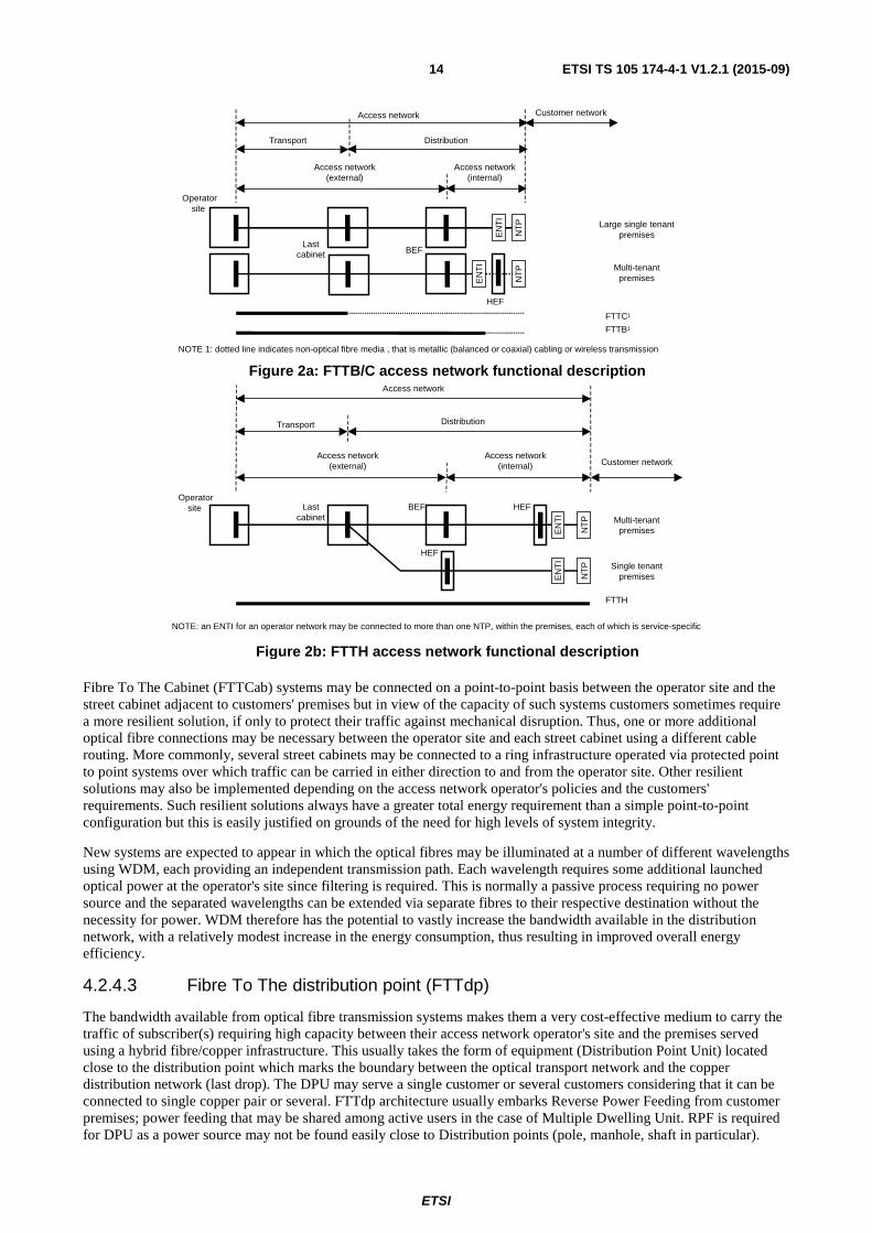
The bandwidth available from optical fibre transmission systems makes them ideal as a shared medium to carry the traffic of a very large number of customers between the operator's site and the customer premises. As a shared medium, it becomes necessary to separate those traffic streams for delivery to their respective customers without being dependent on any one subscriber's facilities (accommodation, power, etc.), in accommodation provided by the access network operator. This usually takes the form of an equipment cabinet located in the street and maintained by the network operator (described as the last cabinet in figures 2a and 2b) which marks the boundary between the transport and distribution parts of the access network. The distribution of the individual customer services comprises secondary transmission systems or sub-loops.
ETSI
ETSI TS 105 174-4-1 V1.2.1 (2015-09) 14
Fibre To The Cabinet (FTTCab) systems may be connected on a point-to-point basis between the operator site and the street cabinet adjacent to customers' premises but in view of the capacity of such systems customers sometimes require a more resilient solution, if only to protect their traffic against mechanical disruption. Thus, one or more additional optical fibre connections may be necessary between the operator site and each street cabinet using a different cable routing. More commonly, several street cabinets may be connected to a ring infrastructure operated via protected point to point systems over which traffic can be carried in either direction to and from the operator site. Other resilient solutions may also be implemented depending on the access network operator's policies and the customers' requirements. Such resilient solutions always have a greater total energy requirement than a simple point-to-point configuration but this is easily justified on grounds of the need for high levels of system integrity.
New systems are expected to appear in which the optical fibres may be illuminated at a number of different wavelengths using WDM, each providing an independent transmission path. Each wavelength requires some additional launched optical power at the operator's site since filtering is required. This is normally a passive process requiring no power source and the separated wavelengths can be extended via separate fibres to their respective destination without the necessity for power. WDM therefore has the potential to vastly increase the bandwidth available in the distribution network, with a relatively modest increase in the energy consumption, thus resulting in improved overall energy efficiency.
4.2.4.3 Fibre To The distribution point (FTTdp)
The bandwidth available from optical fibre transmission systems makes them a very cost-effective medium to carry the traffic of subscriber(s) requiring high capacity between their access network operator's site and the premises served using a hybrid fibre/copper infrastructure. This usually takes the form of equipment (Distribution Point Unit) located close to the distribution point which marks the boundary between the optical transport network and the copper distribution network (last drop). The DPU may serve a single customer or several customers considering that it can be connected to single copper pair or several. FTTdp architecture usually embarks Reverse Power Feeding from customer premises; power feeding that may be shared among active users in the case of Multiple Dwelling Unit. RPF is required for DPU as a power source may not be found easily close to Distribution points (pole, manhole, shaft in particular).
NOTE: an ENTI for an operator network may be connected to more than one NTP, within the premises, each of which is service-specific
FTTH
Transport Distribution
Access network
Customer networkAccess network
(internal)Access network
(external)
NT
P
EN
TI
NT
P
EN
TI
BEFLast
cabinet
NOTE 1: dotted line indicates non-optical fibre media , that is metallic (balanced or coaxial) cabling or wireless transmission
NT
P
EN
TI
Customer networkAccess network
Access network(internal)
Access network(external)
Transport Distribution
FTTC1
FTTB1
EN
TI
HEF
NT
PHEFBEF
HEF
Lastcabinet
Operatorsite
Operatorsite
Multi-tenantpremises
Single tenantpremises
Large single tenantpremises
Multi-tenantpremises
Figure 2b: FTTH access network functional description
Figure 2a: FTTB/C access network functional description

ETSI
ETSI TS 105 174-4-1 V1.2.1 (2015-09) 15
As transmission techniques over copper are able to offer a very high bit rate over short distance, the copper distribution point is an adequate location for DPU as final drop cable are less than a few hundred metres long. Consequently, very high bit rate traffic can reach customer premises without fibre installation inside customer premises. Several copper drop pairs may leave the distribution point to reach several customer premises with sometimes a partial common path between some copper pairs. To prevent impact on bit rate due to coupling between copper drop cables sharing partially a same path, DPU may embed a vectoring function.
From an energy consumption point of view, DPU is limited to a few customer (1 to 8) considering power restrictions associated to RPF that currently limits total power launched from a single customer to the DPU to 15 W. Resiliency is not requested at this time on fibre transport network or on copper distribution network as this increases power consumption that DPU cannot afford.
4.2.4.4 Fibre to the Building (FTTB)
The bandwidth available from optical fibre transmission systems makes them a very cost-effective medium to carry the traffic of subscribers requiring high capacity between their access network operator's site and the premises served.
However, where the building accommodates multiple domestic or small commercial organizations, the service delivered to individual subscribers within the building is restricted by the transmission medium between the FTTB interface and the subscriber. There is generally no requirement for resilient solutions between individual subscribers and the operator's site since although certain subscribers may have significant demands for high data throughput there is no lifeline quality required for those residential "best effort" services.
Where the building accommodates more demanding commercial entities it may be necessary to provide a resilient solution to ensure service continuity. Thus, in a similar manner to that noted for the FTTCab case outlined in clause 4.2.4.2, two or more optical fibre connections may be needed to such premises using different cable routings. These diverse routings may even be connected to different operator sites, and possibly even to different operator networks where extreme reliability is a business necessity. Other resilient solutions may also be implemented depending on the access network operator's policies and the customer's particular requirements. Any such resilient solutions invariably have a greater total energy requirement than the single attachment configuration, and depending on the protection scheme may go up to twice the figure applicable in an unprotected access network or even higher if such requirement remains low.
4.2.4.5 Fibre to the Home (FTTH)
The bandwidth available from optical fibre transmission systems makes Fibre a very cost-effective medium to carry the traffic of subscribers requiring considerable capacity between their access network operator's site and the individual subscribers served.
There is generally no requirement for resilient solutions between the subscriber and the operator site since although certain subscribers may have significant demands for data throughput, primarily for entertainment purposes, the criticality of those services is comparatively low.
4.2.5 Other access technologies
A number of other telecommunications access technologies are available including power line transmission systems, point to point laser-based links and satellite access systems, Each of these suffers from one or more of a variety of disadvantages (low bandwidth, poor reliability, high cost, etc.) and whilst they are all valuable in certain niche markets, none is generally suitable for high-bandwidth, high-reliability, low-cost, mass-market communications systems.
Such applications are not expected to be significant consumers of energy in the access network and thus are not discussed further in the present document.
4.3 Up to 400 VDC versus AC The increase of service and of energy density of the telecommunications and datacom (ICT) equipment has led to more equipment in the same existing premises and higher power consumption.
The telecom equipment are commonly powered in 48 VDC and the servers in AC, e.g. three phases 400 VAC distribution and 230 VAC single phase at 50 Hz in Europe.
ETSI
ETSI TS 105 174-4-1 V1.2.1 (2015-09) 16
Therefore, the A3 power interface voltage ranges proposed in ETSI EN 300 132 series [i.19] have been defined with consideration to the:
• Need to unify the power supply to all telecommunications and datacom (ICT) Equipment.
• Reduction of the power losses as well as copper cross-section area in the power distribution wires.
• Need to maintain a highly reliable power source for telecommunications and datacom.
ETSI EN 300 132-3-1 [i.20] defines the requirements for the up to 400 VDC power interface at the input of the telecommunications and datacom (ICT) equipment fed from the site power plant, and includes requirements relating to its stability and measurement.
The up to 400 VDC power feeding solution for ICT sites and other building using the up to 400 VDC power interface, are well adapted to renewable energy or distributed sources or new micro-grids (see ETSI TS 105 174-2 [i.21], clause 10.2.3), most of them being more complex in AC than in DC. The DC allows great simplification by avoiding frequency synchronization.
Many documents, studies, and standards suggest that direct DC can generate some savings from 5 % to 15 % depending on several conditions. Such as generation of AC equipment, load of the site, etc.
Technically, telecom equipment from main vendors could accept direct up to 400 VDC voltage range defined in ETSI EN 300 132-3-1 [i.20] and such equipment progressively gets available.
In the meantime, the solution proposed by energy vendors is using very high efficiency DC interface converters A3/A from up to 400 VDC range to -48 VDC range as defined in ETSI EN 300 132 series [i.19]. The benefit is a strong reduction of copper use in the distribution (typically a factor 10 in mass), while reducing losses from 1 % or 2 %, which is compensating the losses in the converters of about 1 % or 2 % also. The cost saving of copper is so big that it can pay the over cost of these converters even when they are redundant.
5 Energy efficiency standards and metrics
5.1 Review of activities outside ETSI
5.1.1 Broadband Code of Conduct
The Broadband Code of Conduct [i.1] provides the power consumption objectives of the Fixed Access Nodes according to the technology (DSL, PON or POTS). The Broadband Code of Conduct [i.1] sets out the basic principles to be followed by all parties involved in broadband equipment, in respect of energy efficient equipment.
5.2 Monitoring of energy management
5.2.1 Generalities
ETSI ES 205 200-3 [i.24] has been developed by ETSI ATTM with the support of ETSI ISG OEU members (ICT world Users) in order to define the most efficient tools.
ETSI ES 205 200-3 [i.24] defines the so-called Global Key Performance Indicators (Global KPIs), it shall enable the monitoring of ICT sites energy management.
ETSI ES 205 200-3 [i.24] proposes a single Global KPI (DCEM), Data processing and Communication Energy
Management, which combines four Objective KPIs. The energy management efficiency of ICT sites of the whole industry shall be benchmarked by these Global KPIs.
ETSI
ETSI TS 105 174-4-1 V1.2.1 (2015-09) 17
5.2.2 Objective Key Performance Indicators
5.2.2.1 Definitions
The Objective KPIs described in ETSI GS OEU 012 [i.18] relate to specific elements of energy management for operational infrastructures under the control of operators as follows:
• energy consumption (KPIEC): the total consumption of energy by an operational infrastructure;
• task efficiency (KPITE): a measure of the work done for a given amount of energy consumed (closer to former
PUE);
• energy re-use (KPIREUSE): is the yearly energy reuse rate transfer or conversion of energy produced by the
operational infrastructure to do other work;
• renewable energy (KPIREN): is the yearly use rate of energy coming from dedicated generation systems using
resources that are naturally replenished.
The set of Objective KPIs are used to define a Global KPI (KPIDCEM) that allows benchmarking the energy
management efficiency of ICT sites depending on their gauge.
5.2.2.2 Energy consumption in FAN sites
As given in ETSI GS OEU 012 [i.18]:
KPIEC = ECDC
And
HE
DCTE EC
ECKPI =
5.2.3 Global KPI
5.2.3.1 DCEM in a site
The Global operational KPI reflects the overall performance of the operational infrastructures against wider energy management targets.
KPIDCEM is composed of two values, DCG and DCP, where:
• DCG defines the energy consumption gauge of the DC;
• DCP defines the performance of the DC for the relevant gauge.
Table 2: Default Gauges (DCG)
DCG KPIEC range
XXS KPIEC ≤ 0,04 GWh
XS 0,04 GWh < KPIEC ≤ 0,2 GWh
S 0,2 GWh < KPIEC ≤ 1 GWh
M 1 GWh < KPIEC ≤ 5 GWh
L 5 GWh < KPIEC ≤ 25 GWh
XL 25 GWh < KPIEC ≤ 100 GWh
XXL KPIEC > 100 GWh

ETSI
ETSI TS 105 174-4-1 V1.2.1 (2015-09) 18
Table 3: Default Classes of DCP
DC commissioning date
since 2005 (see note)
before 2005 (see note)
DCP DCP Class ≥ < ≥ <
A 0,70 1,00 B 0,70 1,00 1,00 1,40 C 1,00 1,30 1,40 1,70 D 1,30 1,50 1,70 1,90 E 1,50 1,70 1,90 2,10 F 1,70 1,90 2,10 2,30 G 1,90 2,10 2,30 2,50 H 2,10 2,40 2,50 2,70 I 2,40 2,70
NOTE: Year of Kyoto Protocol entering into force.
The following formula applies to the calculation of DCP for all the gauges:
( ) ( )RENRENREUSEREUSETEP KPIWKPIWKPIDC ×−××−×= 11
Where:
WREUSE = Mitigation factor for KPIREUSE (the value may vary depending on the gauge within the range
0 to 1, the default value is 0,5). WREN = Mitigation factor for KPIREN (the value may vary depending on the gauge within the range
0 to 1, the default value is 0,5).
The Global KPIDCEM is presented as a combination of the two values, DCG and DCP, in the following form: Gauge
(see table 2), Class (see table 3), e.g. M, C.
All measurement points and processes of all KPI(s) for sites are described in ETSI GS OEU 012 [i.18].
5.2.3.2 Global KPI (KPIDCEM) for a group of ICT sites
The set of Objective KPIs as defined in clause 5.2 are used to define a Global KPI (KPIDCEM) for a group of sites. That
allows benchmarking the energy management efficiency of a group of Broadband fixed access sites depending on its gauge.
DCEM is composed of two values: Energy consumption Gauge and Class. The Gauge depends on the global energy
consumption by all the fixed access sites in the group and the Class is a weighted average of all classes.
For a Group of Broadband fixed access sites: = for site i.
KPIECG is the total consumption of energy by the group of sites.
The default number of DCG gauges is seven as shown in table 4 and can be adapted by the user of the KPIDCEM.
Table 4: Default Gauges (DCG)
DCG KPIECG range
XXS KPIEC ≤ 0,4 GWh
XS 0,4 GWh < KPIEC ≤ 2 GWh
S 2 GWh < KPIEC ≤ 10 GWh
M 10 GWh < KPIEC ≤ 50 GWh
L 50 GWh < KPIEC ≤ 250 GWh
XL 250 GWh < KPIEC ≤ 1 000 GWh
XXL KPIEC > 1 000 GWh
∑=
=n
iECECG iKPIKPI
1
)( ECKPI

ETSI
ETSI TS 105 174-4-1 V1.2.1 (2015-09) 19
The class associated with a group of fixed access sites is a weighted average of all sites classes and the DCp is the same
as the table 3.
Where:
• n = the number of sites in the group of fixed access sites.
• NumClass (i) = class number for the site (i) which takes the values between A to I (see table 3).
)(
)(*)(
1
1
iKPI
iKPIiNumClassNumClassG
n
i
EC
EC
n
i
∑
∑
=
==

ETSI
ETSI TS 105 174-4-1 V1.2.1 (2015-09) 20
Annex A (informative): Relationship between KPI(s) Operational Global and Objective KPIs are fundamentally different from the Technical KPIs applied to products and systems at the design and engineering stages. The former are used to monitor and drive user behaviour whereas the latter are substantial indications of potential operational performance.
Technical KPIs can be applied to the clause 5 by assessing energy consumption for a number of specific operating conditions and also across a combination of such operating conditions. Assuming those operating conditions reflect the probable operating environment for the component, sub-assembly or product, a customer may make valued judgements in relation to the appropriateness of the Technical KPI.
It is therefore important to support, but differentiate, the role of the Technical KPIs from the Objective and Global operational KPIs.
Figure A.1: The relationship of energy-related Technical, Objective and Global KPIs
More complex products may contain hardware and/or software which automatically reduce energy consumption under specific operating conditions by putting certain functions into "idle" states if not required.
Components
Sub-assemblies
Products
Systems
Energy consumption
Task efficiency
TECHNICAL KPI
TECHNICAL KPI
PR
OD
UC
T A
ND
SY
YS
TE
MC
AP
AB
ILIT
Y
Energy consumption
Task efficiency
OBJECTIVE KPI
OBJECTIVE KPI
INS
TA
LLA
TIO
N, C
ON
FIG
UR
AT
ION
AN
D O
PE
RA
TIO
N
FO
R E
XT
EN
DE
D P
ER
IOD
Energy re-use
Renewablecontribution
OBJECTIVE KPI
OBJECTIVE KPIEnergy
management
GLOBAL KPI
DESIGN AND ENGINEERING
SYSTEM OPERATION
ETSI
ETSI TS 105 174-4-1 V1.2.1 (2015-09) 21
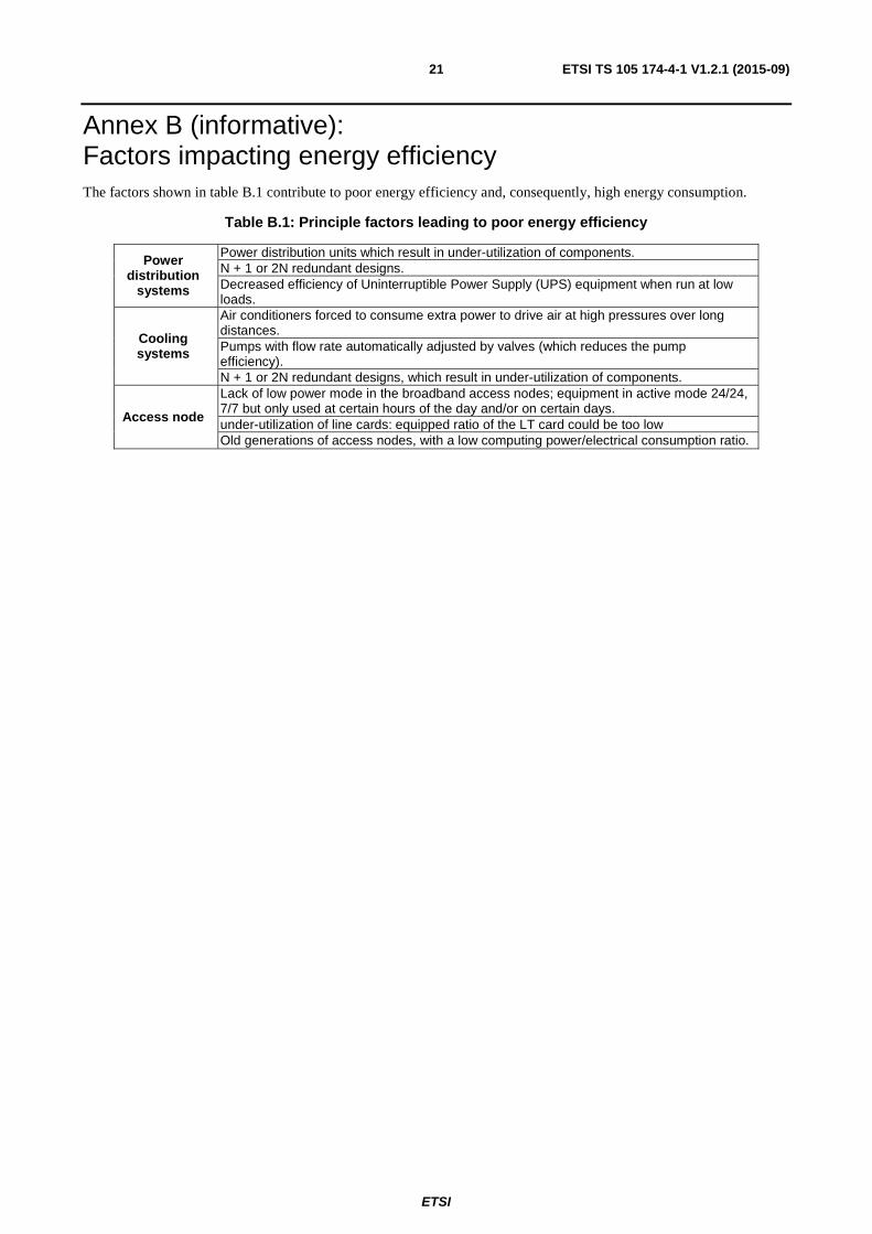
Annex B (informative): Factors impacting energy efficiency The factors shown in table B.1 contribute to poor energy efficiency and, consequently, high energy consumption.
Table B.1: Principle factors leading to poor energy efficiency
Power distribution
systems
Power distribution units which result in under-utilization of components. N + 1 or 2N redundant designs. Decreased efficiency of Uninterruptible Power Supply (UPS) equipment when run at low loads.
Cooling systems
Air conditioners forced to consume extra power to drive air at high pressures over long distances. Pumps with flow rate automatically adjusted by valves (which reduces the pump efficiency). N + 1 or 2N redundant designs, which result in under-utilization of components.
Access node
Lack of low power mode in the broadband access nodes; equipment in active mode 24/24, 7/7 but only used at certain hours of the day and/or on certain days. under-utilization of line cards: equipped ratio of the LT card could be too low Old generations of access nodes, with a low computing power/electrical consumption ratio.

ETSI
ETSI TS 105 174-4-1 V1.2.1 (2015-09) 22
Annex C (informative): Bibliography ETSI TR 102 530: "Environmental Engineering (EE); The reduction of energy consumption in telecommunications equipment and related infrastructure".
ETSI TS 102 533: "Environmental Engineering (EE); Measurement Methods and limits for Energy Consumption in Broadband Telecommunication Networks Equipment".
Recommendation ITU-T G.983.1 (05/2005): "Broadband optical access systems based on Passive Optical Networks (PON)".
Recommendation ITU-T G.983.2 (01/2007): "ONT management and control interface specification for B-PON".
Recommendation ITU-T G.983.3 (07/2005): "A broadband optical access system with increased service capability by wavelength allocation".
Recommendation ITU-T G.983.4 (01/2005): "A broadband optical access system with increased service capability using dynamic bandwidth assignment".
Recommendation ITU-T G.983.5 (01/2002): "A broadband optical access system with enhanced survivability".
Recommendation ITU-T G.988 (10/2012): "Optical network unit management and control interface specification".
ETSI TS 105 174-5-1: "Access, Terminals, Transmission and Multiplexing (ATTM); Broadband Deployment and Energy Management; Part 5: Customer network infrastructures; Sub-part 1: Homes (single-tenant)".
ETSI ES 205 200-2-2: "Access, Terminals, Transmission and Multiplexing (ATTM); Energy management; Global KPIs; Operational infrastructures; Part 2: Specific requirements; Sub-part 2: Fixed Broadband access networks".

ETSI
ETSI TS 105 174-4-1 V1.2.1 (2015-09) 23
History
Document history
V1.1.1 October 2009 Publication as TR 105 174-4
V1.2.1 September 2015 Publication