
TS 102 402 - V1.1.1 - Satellite Earth Station and systems ... TS 102 402 V1.1.1 (2005-05) Technical...
34
ETSI TS 102 402 V1.1.1 (2005-05) Technical Specification Satellite Earth Station and systems (SES); Broadband Satellite Multimedia; Transparent Satellite Star - A (TSS-A); DVB-S and DVB-RCS for transparent satellites; Sub-family 1 (TSS-A1)
-
Upload
phungthuan -
Category
Documents
-
view
228 -
download
0
Transcript of TS 102 402 - V1.1.1 - Satellite Earth Station and systems ... TS 102 402 V1.1.1 (2005-05) Technical...
ETSI TS 102 402 V1.1.1 (2005-05)
Technical Specification
Satellite Earth Station and systems (SES);Broadband Satellite Multimedia;
Transparent Satellite Star - A (TSS-A);DVB-S and DVB-RCS for transparent satellites;
Sub-family 1 (TSS-A1)
ETSI
ETSI TS 102 402 V1.1.1 (2005-05) 2
Reference DTS/SES-00273
Keywords air interface, DVB, architecture, broadband
ETSI
650 Route des Lucioles F-06921 Sophia Antipolis Cedex - FRANCE
Tel.: +33 4 92 94 42 00 Fax: +33 4 93 65 47 16
Siret N° 348 623 562 00017 - NAF 742 C
Association à but non lucratif enregistrée à la Sous-Préfecture de Grasse (06) N° 7803/88
Important notice
Individual copies of the present document can be downloaded from: http://www.etsi.org
The present document may be made available in more than one electronic version or in print. In any case of existing or perceived difference in contents between such versions, the reference version is the Portable Document Format (PDF).
In case of dispute, the reference shall be the printing on ETSI printers of the PDF version kept on a specific network drive within ETSI Secretariat.
Users of the present document should be aware that the document may be subject to revision or change of status. Information on the current status of this and other ETSI documents is available at
http://portal.etsi.org/tb/status/status.asp
If you find errors in the present document, please send your comment to one of the following services: http://portal.etsi.org/chaircor/ETSI_support.asp
Copyright Notification
No part may be reproduced except as authorized by written permission. The copyright and the foregoing restriction extend to reproduction in all media.
© European Telecommunications Standards Institute 2005.
All rights reserved.
DECTTM, PLUGTESTSTM and UMTSTM are Trade Marks of ETSI registered for the benefit of its Members. TIPHONTM and the TIPHON logo are Trade Marks currently being registered by ETSI for the benefit of its Members. 3GPPTM is a Trade Mark of ETSI registered for the benefit of its Members and of the 3GPP Organizational Partners.
ETSI
ETSI TS 102 402 V1.1.1 (2005-05) 3
Contents
Intellectual Property Rights ................................................................................................................................5
Foreword.............................................................................................................................................................5
Introduction ........................................................................................................................................................5
1 Scope ........................................................................................................................................................6
2 References ................................................................................................................................................7
3 Definitions and abbreviations...................................................................................................................8 3.1 Definitions..........................................................................................................................................................8 3.2 Abbreviations .....................................................................................................................................................9
4 Architecture............................................................................................................................................10 4.1 Overall architecture ..........................................................................................................................................10 4.1.1 Star topology...............................................................................................................................................10 4.1.2 Connectivity................................................................................................................................................11 4.1.3 Transparent Satellite ...................................................................................................................................11 4.1.4 Satellite Forward and Return Channels ......................................................................................................11 4.2 Hub station .......................................................................................................................................................11 4.2.1 Overview ....................................................................................................................................................11 4.2.2 Interface to a terrestrial network .................................................................................................................12 4.2.3 Forward Link Sub-system...........................................................................................................................12 4.2.3.1 DVB Gateway .......................................................................................................................................12 4.2.3.2 DVB-S signal format.............................................................................................................................12 4.2.4 Return Link Sub-system .............................................................................................................................13 4.2.5 Network Management System....................................................................................................................13 4.2.6 Network Control Centre..............................................................................................................................13 4.3 Satellite Terminal .............................................................................................................................................13 4.3.1 Overview ....................................................................................................................................................13 4.3.2 Interworking Unit .......................................................................................................................................14 4.3.3 Satellite Terminal Return Link sub-system ................................................................................................14 4.3.3.1 Cell processor........................................................................................................................................14 4.3.3.2 DVB-RCS signal format .......................................................................................................................15 4.3.4 Satellite Terminal Forward Link sub-system..............................................................................................15 4.3.5 Management agent ......................................................................................................................................15 4.3.6 Control Unit ................................................................................................................................................15
5 Internetworking with and within TSS-A1 ..............................................................................................15 5.1 Internetworking ................................................................................................................................................15 5.2 IP scenarios ......................................................................................................................................................16 5.3 Main IP services ...............................................................................................................................................16 5.4 Forwarding on the air interface ........................................................................................................................16 5.4.1 Unicast ........................................................................................................................................................17 5.4.2 Multicast and broadcast ..............................................................................................................................17
6 Profile for DVB-S and DVB-RCS: commonalities to all planes............................................................17 6.1 Satellite Independent Service Access Point......................................................................................................17 6.2 Types of payload ..............................................................................................................................................17 6.3 MAC and Data Link layer ................................................................................................................................19 6.3.1 Forward link................................................................................................................................................19 6.3.1.1 Multi Protocol Encapsulation................................................................................................................19 6.3.1.2 The MPEG2 Transport Stream..............................................................................................................19 6.3.2 Return link: multiple access and superframes.............................................................................................20 6.4 Physical layer ...................................................................................................................................................22 6.4.1 Forward link................................................................................................................................................22 6.4.2 Return link ..................................................................................................................................................22 6.4.2.1 General ..................................................................................................................................................22 6.4.2.2 Return link emission at the STs: burst format .......................................................................................23
ETSI
ETSI TS 102 402 V1.1.1 (2005-05) 4
7 Profile in the Data plane.........................................................................................................................23 7.1 Forward Link: IP over DVB-S .........................................................................................................................23 7.1.1 Useful bit rate .............................................................................................................................................23 7.1.2 Mac and Data link layer..............................................................................................................................23 7.1.2.1 Addressing ............................................................................................................................................23 7.2 Return Link: IP over DVB-RCS.......................................................................................................................23 7.2.1 Useful bit rate .............................................................................................................................................23 7.2.2 Data Link layer: ATM format.....................................................................................................................23 7.2.3 Physical layer: traffic bursts........................................................................................................................24
8 Profile in the Control Plane ....................................................................................................................24 8.1 Signalling on the Forward Link........................................................................................................................24 8.1.1 General Information: Service Information tables .......................................................................................24 8.1.2 Terminal Information Message...................................................................................................................25 8.1.3 Network Clock Reference...........................................................................................................................25 8.2 Signalling on the Return Link ..........................................................................................................................25 8.2.1 Burst types and their format........................................................................................................................25 8.2.2 Capacity requests and capacity categories ..................................................................................................26 8.3 Synchronization................................................................................................................................................26 8.3.1 General........................................................................................................................................................26 8.3.2 Synchronization procedures........................................................................................................................27 8.3.2.1 Overall events sequencing.....................................................................................................................27 8.3.2.2 Logon procedure ...................................................................................................................................28 8.3.2.3 Enhanced coarse synchronization procedure.........................................................................................28
9 Management ...........................................................................................................................................29 9.1 General concepts and features ..........................................................................................................................29 9.2 Specific vs. common functions.........................................................................................................................29 9.3 Protocol ............................................................................................................................................................30 9.4 Management Information Bases.......................................................................................................................30 9.5 ST configuration...............................................................................................................................................31 9.6 Management and Control .................................................................................................................................31
10 Security...................................................................................................................................................31 10.1 Data protection .................................................................................................................................................31 10.1.1 Upper layers mechanisms ...........................................................................................................................31 10.1.2 Forward link: DVB-S Conditional Access..................................................................................................32 10.2 Protection of resource.......................................................................................................................................32 10.3 Miscellaneous...................................................................................................................................................32
Annex A (informative): Bibliography...................................................................................................33
History ..............................................................................................................................................................34
ETSI
ETSI TS 102 402 V1.1.1 (2005-05) 5
Intellectual Property Rights IPRs essential or potentially essential to the present document may have been declared to ETSI. The information pertaining to these essential IPRs, if any, is publicly available for ETSI members and non-members, and can be found in ETSI SR 000 314: "Intellectual Property Rights (IPRs); Essential, or potentially Essential, IPRs notified to ETSI in respect of ETSI standards", which is available from the ETSI Secretariat. Latest updates are available on the ETSI Web server (http://webapp.etsi.org/IPR/home.asp).
Pursuant to the ETSI IPR Policy, no investigation, including IPR searches, has been carried out by ETSI. No guarantee can be given as to the existence of other IPRs not referenced in ETSI SR 000 314 (or the updates on the ETSI Web server) which are, or may be, or may become, essential to the present document.
Foreword This Technical Specification (TS) has been produced by ETSI Technical Committee Satellite Earth Stations and Systems (SES).
Introduction While the DVB-S standard [3] enables broadband services via satellite in one direction, the need for a return channel via satellite has appeared. This was standardized by DVB-RCS standards [2] and [8].
DVB-RCS may be described as a development of VSAT systems which already offer broadband services such as Internet access, multicasting, VPN. DVB-RCS is the easy way to provide interactive broadband over satellite.
A DVB-RCS based network can be configured as a star network, which supports communications in the forward channel from the Hub station to many Terminals, functioning according to DVB-S, and in the return channel from the Terminals to the Hub station.
We envisage here a solution suitable for both the professional and the residential markets.
ETSI
ETSI TS 102 402 V1.1.1 (2005-05) 6
1 Scope The present document has been produced by the ETSI Technical Committee Satellite Earth Station and Systems (TC SES) Broadband Satellite Multimedia (BSM) working group. It defines BSM air interface subfamily Transparent Satellite Star - A1 (TSS-A1) using DVB-RCS and DVB-S with transparent satellite so support interworking with IP multimedia and services.
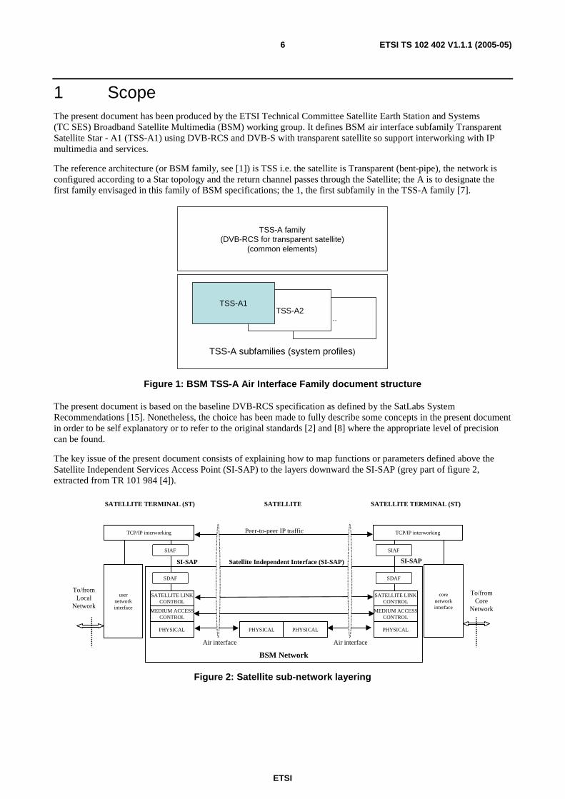
The reference architecture (or BSM family, see [1]) is TSS i.e. the satellite is Transparent (bent-pipe), the network is configured according to a Star topology and the return channel passes through the Satellite; the A is to designate the first family envisaged in this family of BSM specifications; the 1, the first subfamily in the TSS-A family [7].
TSS-A subfamilies (system profiles)
..TSS-A2
TSS-A1
TSS-A family(DVB-RCS for transparent satellite)
(common elements)
Figure 1: BSM TSS-A Air Interface Family document structure
The present document is based on the baseline DVB-RCS specification as defined by the SatLabs System Recommendations [15]. Nonetheless, the choice has been made to fully describe some concepts in the present document in order to be self explanatory or to refer to the original standards [2] and [8] where the appropriate level of precision can be found.
The key issue of the present document consists of explaining how to map functions or parameters defined above the Satellite Independent Services Access Point (SI-SAP) to the layers downward the SI-SAP (grey part of figure 2, extracted from TR 101 984 [4]).
BSM Network
MEDIUM ACCESSCONTROL
SATELLITE LINKCONTROL
TCP/IP interworking
corenetworkinterface
PHYSICAL
MEDIUM ACCESSCONTROL
SATELLITE LINKCONTROL
TCP/IP interworking
usernetworkinterface
PHYSICAL PHYSICAL PHYSICAL
To/fromCore
Network
To/fromLocal
Network
Air interfaceAir interface
SATELLITE
SI-SAP
SATELLITE TERMINAL (ST) SATELLITE TERMINAL (ST)
SI-SAPSatellite Independent Interface (SI-SAP)
Peer-to-peer IP traffic
SDAF SDAF
SIAF SIAF
Figure 2: Satellite sub-network layering

ETSI
ETSI TS 102 402 V1.1.1 (2005-05) 7
2 References The following documents contain provisions which, through reference in this text, constitute provisions of the present document.
• References are either specific (identified by date of publication and/or edition number or version number) or non-specific.
• For a specific reference, subsequent revisions do not apply.
• For a non-specific reference, the latest version applies.
Referenced documents which are not found to be publicly available in the expected location might be found at http://docbox.etsi.org/Reference.
[1] ETSI TR 102 187: "Satellite Earth Stations and Systems (SES); Broadband Satellite Multimedia; Overview of BSM families".
[2] ETSI EN 301 790: "Digital Video Broadcasting (DVB); Interaction channel for satellite distribution systems".
[3] ETSI EN 300 421: "Digital Video Broadcasting (DVB); Framing Structure, Channel Coding and Modulation for 11/12 GHz Satellite Services".
[4] ETSI TR 101 984: "Satellite Earth Stations and Systems (SES); Broadband Satellite Multimedia; Services and Architectures".
[5] ETSI TR 101 985: "Satellite Earth Stations and Systems (SES); Broadband Satellite Multimedia; IP over satellite".
[6] ETSI EN 301 192 (V1.2.1): "Digital Video Broadcasting (DVB); DVB specification for data broadcasting".
[7] ETSI EN 102 352: "Satellite Earth Stations and Systems (SES); Broadband Satellite Multimedia; Transparent Satellite Star -A (TSS-A) DVB-S/DVB-RCS for transparent satellites".
[8] ETSI TR 101 790: "Digital Video Broadcasting (DVB); Interaction channel for satellite distribution systems; Guidelines for the use of EN 301 790".
[9] ETSI EN 300 468: "Digital Video Broadcasting (DVB); Specification for Service Information (SI) in DVB systems".
[10] ISO/IEC 13818-1: "Information Technology - Generic coding of moving pictures and associated audio information: Systems".
[11] IETF RFC 1901: "Introduction to Community-based SNMPv2".
[12] IETF RFC 1213: "Management Information Base for Network Management of TCP/IP-based internets: MIB-II".
[13] IETF RFC 1155: "Structure and identification of management information for TCP/IP-based Internets".
[14] ETSI TR 101 202 (V1.2.1): "Digital Video Broadcasting; Implementation Guidelines for Data Broadcasting".
[15] SatLabs System Recommendations.
NOTE: http://satlabs.org
[16] IETF RFC 2684: "Multiprotocol Encapsulation over ATM Adaptation Layer 5".
[17] ETSI TR 102 287: "Satellite Earth Stations and Systems (SES); Broadband Satellite Multimedia (BSM); IP Interworking over satellite; Security aspects".

ETSI
ETSI TS 102 402 V1.1.1 (2005-05) 8
[18] ETSI ETR 289: "Digital Video Broadcasting (DVB); Support for use of scrambling and Conditional Access (CA) within digital broadcasting systems".
[19] IETF RFC 1112: "Host extensions for IP multicasting".
[20] IETF RFC 2401: "Security Architecture for the Internet Protocol".
3 Definitions and abbreviations
3.1 Definitions For the purposes of the present document, the terms and definitions given in EN 301 790 [2], TR 101 790 [8], SatLabs System Recommendations [15] and the following apply:
bearer service: telecommunication service that provides the capability of transmission of signals between access points
broadcast: communication capability which denotes unidirectional distribution to an unspecified number of access points connected to the network
control plane: plane which performs the call control and connection control functions, and deals with the signalling necessary to set up, supervise and release calls and connections
data piping: mode for conveying data over protocols of the DVB family where discrete pieces of data are delivered using containers (MPEG2 packetized elementary streams) to the destination without any control information
data streaming: mode for conveying data over protocols of the DVB family where the data takes the form of a continuous stream which may be Asynchronous (i.e. without timing, as for Internet packet data), Synchronous (i.e. tied to a fixed rate transmission clock, as for emulation of a synchronous communication link) or Synchronized (i.e. tied via time stamps to the decoder clock and hence to other PES packets, as for the display of TV captions)
Digital Video Broadcasting Return Channel Satellite (DVB-RCS): protocol for an interaction (or return) channel in satellite links
Digital Video Broadcasting via Satellite (DVB-S): protocol for broadcasting TV signals and by extension data over satellite
management plane: Plane which provides two types of functions, namely layer management and plane management functions
multicast: communication capability which denotes unidirectional distribution from a single source access point to a number of specified destination access points
Quality of Service (QoS): measure of the parameters of a network that influence perceived quality of communications, including the delay, jitter, bandwidth, and packet loss that packets sent by the application experience when being transferred by the network
Transmission Control Protocol (TCP): protocol above IP which provides a reliable, connection oriented, end-to end transport service between hosts
transparent (or bent pipe) satellite: satellite which converts the frequency of incoming signals and amplifies them, the desired carriers as well as the undesired noise, without any additional processing
turbo coding: the most recent and a high performance error correction coding scheme which has proven to be the most efficient in most cases
user plane: Plane which has a layered structure and provides for user information flow transfer, along with associated controls (e.g. flow control, recovery from errors, etc.)
VSAT systems: satellite networks designed to offer broadband services to companies by the means of small dishes
ETSI
ETSI TS 102 402 V1.1.1 (2005-05) 9
3.2 Abbreviations For the purposes of the present document, the following abbreviations apply:
AAA Authorization Authentication Accounting AAL5 ATM Adaptation Layer version 5 ACQ ACQuisition ATM Asynchronous Transfer Mode AVBDC Absolute Volume Based Dynamic Capacity BSM Broadband Satellite Multimedia CA Conditional Access CRA Continuous Rate Assignment CSC Common Signalling Channel DAMA Demand Assigned Multiple Access DSP Digital Signal Processing DVB-RCS Digital Video Broadcasting Return Channel by Satellite DVB-S Digital Video Broadcasting via Satellite FCA Free Capacity Assignment FLSS Forward Link Sub-system GPS Global Positioning System IP Internet Protocol ISP Internet Service Provider LAN Local Area Network MAC Medium Access Control MF-TDMA MultiFrequency Time Division Multiple Access MIB Management Information Base MMT Multicast Mapping Table MPEG2-TS MPEG2 Transport Stream NAT Network Address Translation NCC Network Control Centre NCR Network Clock Reference NMS Network Management System OAM Operation Administration Maintenance PID Programme IDentifier PSI Program Service Information QoS Quality of Service RBDC Rate Based Dynamic Capacity RF Radio Frequency RLSS Return Link Sub-system SAC Satellite Access Control SI Service Information SI-SAP Satellite Independent-Services Access Point SNMP Simple Network Management Protocol SYNC SYNChronization TBTP Terminal Bursts Time Plan TCP Transmission Control Protocol TIM Terminal Information Message TRF TRaFic TSS Transparent Satellite Star VBDC Volume Based Dynamic Capacity VPN Virtually Private Network VSAT Very Small Aperture Satellite Terminal
ETSI
ETSI TS 102 402 V1.1.1 (2005-05) 10
4 Architecture
4.1 Overall architecture
4.1.1 Star topology
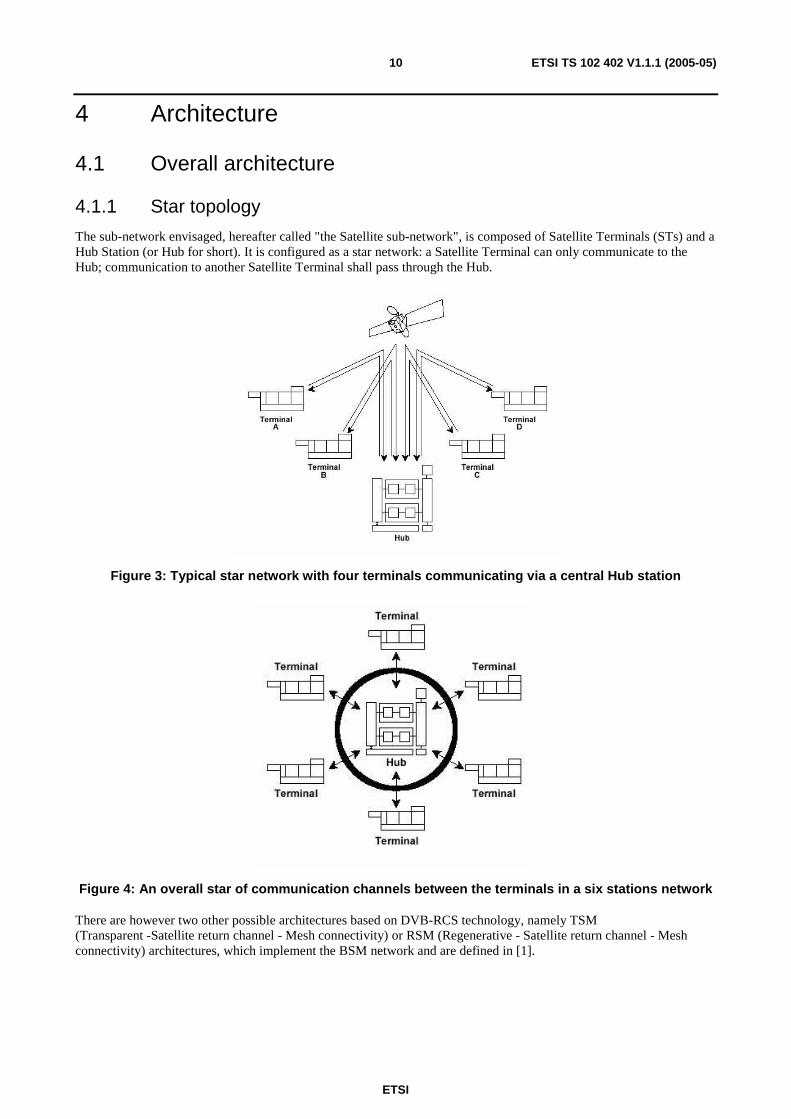
The sub-network envisaged, hereafter called "the Satellite sub-network", is composed of Satellite Terminals (STs) and a Hub Station (or Hub for short). It is configured as a star network: a Satellite Terminal can only communicate to the Hub; communication to another Satellite Terminal shall pass through the Hub.
Figure 3: Typical star network with four terminals communicating via a central Hub station
Figure 4: An overall star of communication channels between the terminals in a six stations network
There are however two other possible architectures based on DVB-RCS technology, namely TSM (Transparent -Satellite return channel - Mesh connectivity) or RSM (Regenerative - Satellite return channel - Mesh connectivity) architectures, which implement the BSM network and are defined in [1].
ETSI
ETSI TS 102 402 V1.1.1 (2005-05) 11
4.1.2 Connectivity
The Satellite sub-network shall be able to be connected to terrestrial backbones at the hub.
The STs shall be able to be connected to a local network of Ethernet type. This local network should not be connected to a network other than the Satellite sub-network; see clause 5.2.
4.1.3 Transparent Satellite
It is assumed that the Satellite sub-network uses a Transparent Satellite.
4.1.4 Satellite Forward and Return Channels
A bi-directional channel shall be established between the Hub and the Satellite Terminals for interaction purposes. It is formed by:
• a Return (or Interaction) Channel, from the Satellite Terminals to the Hub, which shall be used to make requests to a service provider, to answer questions or to transfer data;
• a Forward Channel, from the Hub to the Satellite Terminals, which shall be used to provide content from a service provider to the Satellite Terminals and any other required communication for the interactive service provision.
Forward and Return channels are used in the User, Control and Management Planes.
The Forward Channels shall be compliant with the DVB-S standard [3]; the Return Channels with DVB-RCS standard [15].
4.2 Hub station
4.2.1 Overview
Where the Satellite sub-network is connected to a terrestrial backbone, the Hub should be the only interface between them; see clause 5.2.
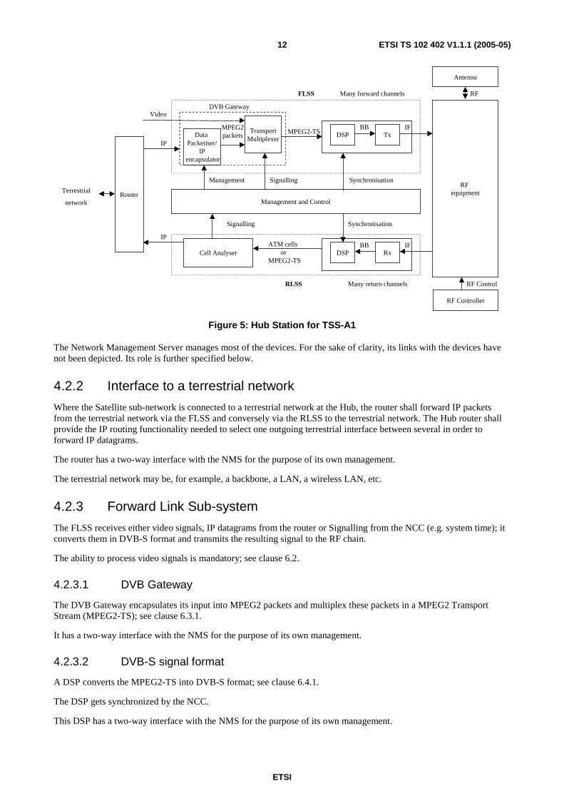
The Hub is composed of:
• a router, routing IP streams coming either from a terrestrial network if any or from the Satellite sub-network;
• a Forward Link Sub-system (FLSS) which processes the signal intended for the Forward Link;
• a Return Link Sub-system (RLSS) which processes the signal coming from the Return Link;
• an RF equipment for conversion from the Intermediate Frequency to the Radio Frequency on the Forward Link and the reverse conversion on the Return Link;
• the Network Control Centre (NCC);
• the Network Management System (NMS) responsible for central (including the STs) and local (i.e. Hub specific) management functions.
ETSI
ETSI TS 102 402 V1.1.1 (2005-05) 12
Terrestrial
network
Cell Analyser
Router
IPATM cells
or MPEG2-TS
DSP RxBB IF
RLSS
Synchronisation
Synchronisation
RF equipment
RF Controller
RF Control
Antenna
RF
Many return channels
Data Packetiser/
IP encapsulator
Signalling
Video
IP
TransportMultiplexer
MPEG2packets
DVB Gateway
DSP TxBB IF
MPEG2-TS
FLSS Many forward channels
Signalling
Management and Control
Management
Figure 5: Hub Station for TSS-A1
The Network Management Server manages most of the devices. For the sake of clarity, its links with the devices have not been depicted. Its role is further specified below.
4.2.2 Interface to a terrestrial network
Where the Satellite sub-network is connected to a terrestrial network at the Hub, the router shall forward IP packets from the terrestrial network via the FLSS and conversely via the RLSS to the terrestrial network. The Hub router shall provide the IP routing functionality needed to select one outgoing terrestrial interface between several in order to forward IP datagrams.
The router has a two-way interface with the NMS for the purpose of its own management.
The terrestrial network may be, for example, a backbone, a LAN, a wireless LAN, etc.
4.2.3 Forward Link Sub-system
The FLSS receives either video signals, IP datagrams from the router or Signalling from the NCC (e.g. system time); it converts them in DVB-S format and transmits the resulting signal to the RF chain.
The ability to process video signals is mandatory; see clause 6.2.
4.2.3.1 DVB Gateway
The DVB Gateway encapsulates its input into MPEG2 packets and multiplex these packets in a MPEG2 Transport Stream (MPEG2-TS); see clause 6.3.1.
It has a two-way interface with the NMS for the purpose of its own management.
4.2.3.2 DVB-S signal format
A DSP converts the MPEG2-TS into DVB-S format; see clause 6.4.1.
The DSP gets synchronized by the NCC.
This DSP has a two-way interface with the NMS for the purpose of its own management.
ETSI
ETSI TS 102 402 V1.1.1 (2005-05) 13
4.2.4 Return Link Sub-system
The RLSS processes the signals coming from the RF chain and sent by the STs; these signals shall conform to the DVB-RCS norm; see clause 6.4.2.
It performs demodulation and decoding of the DVB-RCS signals by means of a DSP; then it extracts IP datagrams that it transmits to the router, or signalling e.g. capacity requests that it transmits to the NCC.
The devices on the RLSS (DSP, ATM Cells analyser) have a two-way interface with the NMS for the purpose of their own management.
4.2.5 Network Management System
The NMS performs the management functions for the Hub equipment and the STs.
The NMS provides means to configure, supervise, monitor, and collect performance data of:
• the Hub's sub-systems;
• the STs.
The NMS plays an essential role in commercial operations of the Satellite sub-network. It shall manage the profiles of the STs and the status of their subscription (e.g. capacity consumed) thus enabling authentication and access to the satellite capacity. (These functions must not be confused with the AAA functions of ISPs).
More details are given in clause 9.
4.2.6 Network Control Centre
The NCC controls the connection of STs to the satellite sub-network (authentication); it allocates satellite resources based on the profiles of the STs collected by the NMS, the requirements of the STs and satellite capacity available. It processes a number of tables describing this allocation and broadcasts them. It accounts for the resource consumed by STs.
It is responsible for system synchronization; it broadcasts a system time reference; it synchronizes the DSPs of the FLSS and RLSS respectively.
The NCC has a two-way interface with the NMS for the purpose of its own management.
More details are given in clause 8.
4.3 Satellite Terminal
4.3.1 Overview
In TSS-A1, the ST shall be of type A as defined in [2], clause 8.1.1.
The ST functional architecture is similar to that of the Hub; see clause 4.2.1.
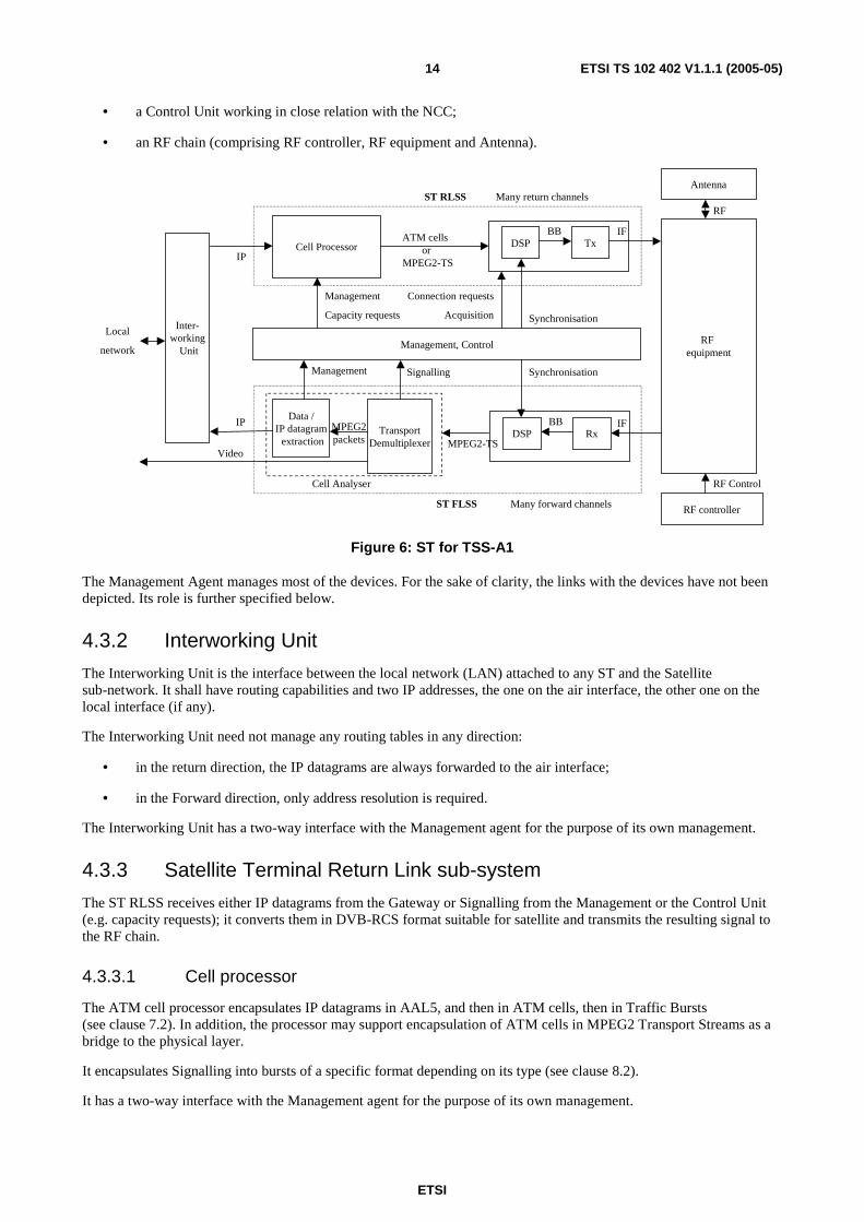
A ST is formed with:
• a Interworking Unit between the local network if any and the Satellite sub-network;
• a Satellite Terminal Return Link Sub-System (ST RLSS) which processes the signal to be transmitted to the Satellite;
• a Satellite Terminal Forward Link Sub-System (ST FLSS) which processes the signal received from the Satellite;
• a Management agent working in close relation with the NMS and in charge of managing local devices;
ETSI
ETSI TS 102 402 V1.1.1 (2005-05) 14
• a Control Unit working in close relation with the NCC;
• an RF chain (comprising RF controller, RF equipment and Antenna).
Cell Processor
Inter-working
Unit
IPData /
IP datagram extraction
Video
IP
Local
network
TransportDemultiplexer
Cell Analyser
ATM cells or
MPEG2-TS
DSP TxBB IF
DSP RxBB IF
MPEG2-TS
ST RLSS
ST FLSS
Synchronisation
RF equipment
RF controller
RF Control
Antenna
RFMany return channels
Many forward channels
Signalling Synchronisation
MPEG2packets
Management, Control
Management
Capacity requests
Connection requests
Acquisition
Management
Figure 6: ST for TSS-A1
The Management Agent manages most of the devices. For the sake of clarity, the links with the devices have not been depicted. Its role is further specified below.
4.3.2 Interworking Unit
The Interworking Unit is the interface between the local network (LAN) attached to any ST and the Satellite sub-network. It shall have routing capabilities and two IP addresses, the one on the air interface, the other one on the local interface (if any).
The Interworking Unit need not manage any routing tables in any direction:
• in the return direction, the IP datagrams are always forwarded to the air interface;
• in the Forward direction, only address resolution is required.
The Interworking Unit has a two-way interface with the Management agent for the purpose of its own management.
4.3.3 Satellite Terminal Return Link sub-system
The ST RLSS receives either IP datagrams from the Gateway or Signalling from the Management or the Control Unit (e.g. capacity requests); it converts them in DVB-RCS format suitable for satellite and transmits the resulting signal to the RF chain.
4.3.3.1 Cell processor
The ATM cell processor encapsulates IP datagrams in AAL5, and then in ATM cells, then in Traffic Bursts (see clause 7.2). In addition, the processor may support encapsulation of ATM cells in MPEG2 Transport Streams as a bridge to the physical layer.
It encapsulates Signalling into bursts of a specific format depending on its type (see clause 8.2).
It has a two-way interface with the Management agent for the purpose of its own management.
ETSI
ETSI TS 102 402 V1.1.1 (2005-05) 15
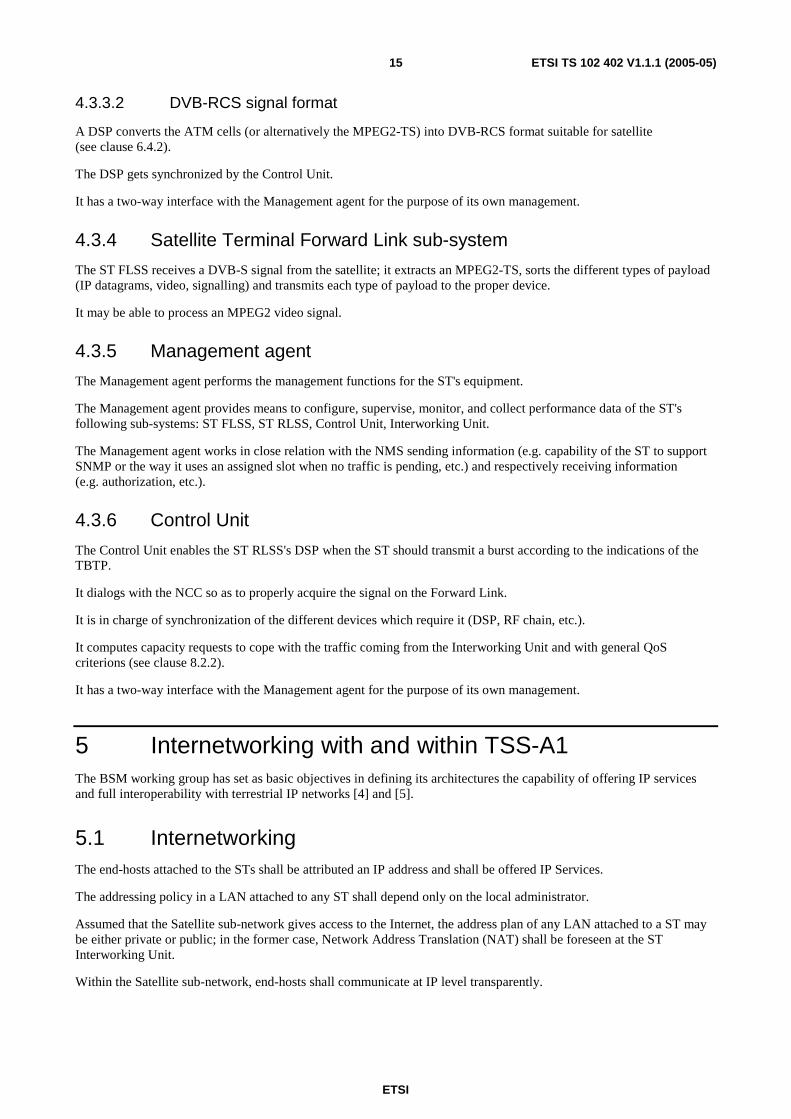
4.3.3.2 DVB-RCS signal format
A DSP converts the ATM cells (or alternatively the MPEG2-TS) into DVB-RCS format suitable for satellite (see clause 6.4.2).
The DSP gets synchronized by the Control Unit.
It has a two-way interface with the Management agent for the purpose of its own management.
4.3.4 Satellite Terminal Forward Link sub-system
The ST FLSS receives a DVB-S signal from the satellite; it extracts an MPEG2-TS, sorts the different types of payload (IP datagrams, video, signalling) and transmits each type of payload to the proper device.
It may be able to process an MPEG2 video signal.
4.3.5 Management agent
The Management agent performs the management functions for the ST's equipment.
The Management agent provides means to configure, supervise, monitor, and collect performance data of the ST's following sub-systems: ST FLSS, ST RLSS, Control Unit, Interworking Unit.
The Management agent works in close relation with the NMS sending information (e.g. capability of the ST to support SNMP or the way it uses an assigned slot when no traffic is pending, etc.) and respectively receiving information (e.g. authorization, etc.).
4.3.6 Control Unit
The Control Unit enables the ST RLSS's DSP when the ST should transmit a burst according to the indications of the TBTP.
It dialogs with the NCC so as to properly acquire the signal on the Forward Link.
It is in charge of synchronization of the different devices which require it (DSP, RF chain, etc.).
It computes capacity requests to cope with the traffic coming from the Interworking Unit and with general QoS criterions (see clause 8.2.2).
It has a two-way interface with the Management agent for the purpose of its own management.
5 Internetworking with and within TSS-A1 The BSM working group has set as basic objectives in defining its architectures the capability of offering IP services and full interoperability with terrestrial IP networks [4] and [5].
5.1 Internetworking The end-hosts attached to the STs shall be attributed an IP address and shall be offered IP Services.
The addressing policy in a LAN attached to any ST shall depend only on the local administrator.
Assumed that the Satellite sub-network gives access to the Internet, the address plan of any LAN attached to a ST may be either private or public; in the former case, Network Address Translation (NAT) shall be foreseen at the ST Interworking Unit.
Within the Satellite sub-network, end-hosts shall communicate at IP level transparently.
ETSI
ETSI TS 102 402 V1.1.1 (2005-05) 16
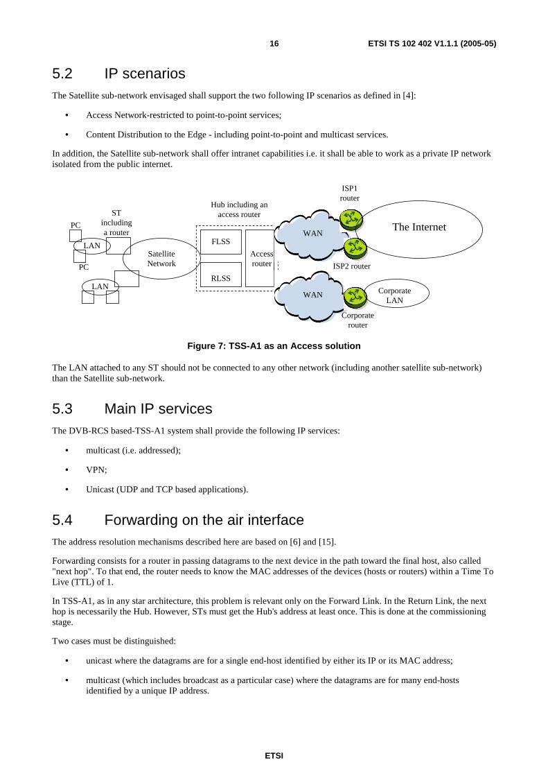
5.2 IP scenarios The Satellite sub-network envisaged shall support the two following IP scenarios as defined in [4]:
• Access Network-restricted to point-to-point services;
• Content Distribution to the Edge - including point-to-point and multicast services.
In addition, the Satellite sub-network shall offer intranet capabilities i.e. it shall be able to work as a private IP network isolated from the public internet.
Hub including anaccess router
FLSS
RLSS
Accessrouter
STincludinga router
SatelliteNetwork
LAN
PC
LAN
PC
WAN
WAN
The Internet
ISP1router
ISP2 router
Corporaterouter
CorporateLAN
Figure 7: TSS-A1 as an Access solution
The LAN attached to any ST should not be connected to any other network (including another satellite sub-network) than the Satellite sub-network.
5.3 Main IP services The DVB-RCS based-TSS-A1 system shall provide the following IP services:
• multicast (i.e. addressed);
• VPN;
• Unicast (UDP and TCP based applications).
5.4 Forwarding on the air interface The address resolution mechanisms described here are based on [6] and [15].
Forwarding consists for a router in passing datagrams to the next device in the path toward the final host, also called "next hop". To that end, the router needs to know the MAC addresses of the devices (hosts or routers) within a Time To Live (TTL) of 1.
In TSS-A1, as in any star architecture, this problem is relevant only on the Forward Link. In the Return Link, the next hop is necessarily the Hub. However, STs must get the Hub's address at least once. This is done at the commissioning stage.
Two cases must be distinguished:
• unicast where the datagrams are for a single end-host identified by either its IP or its MAC address;
• multicast (which includes broadcast as a particular case) where the datagrams are for many end-hosts identified by a unique IP address.

ETSI
ETSI TS 102 402 V1.1.1 (2005-05) 17
5.4.1 Unicast
In the Forward Link, the MAC address of any ST is the MAC address of its DVB-S receiver. It shall be stored at the Hub in some data structure at the commissioning of the ST. As for the ST's IP address, if it is static, it shall also be stored at the commissioning stage; if it is dynamic there must be some mechanism (e.g. DHCP with the server on the Hub side) to associate an IP address with the ST's MAC address; this mechanism is in charge of storing address pairs.
Subsequently, the DVB Gateway shall detect IP streams, encapsulate them in MPE packets and fill in the MAC field of the packets with the ST's MAC address. If MPE packets do not have the right MAC address, they are silently discarded by the receiver.
The PID shall not be used to uniquely identify any ST (see clause 6.3.1.2).
5.4.2 Multicast and broadcast
TSS-A1 provides the multicast capability on the Forward Link.
NOTE: Direct transmission of IP multicast (i.e. with class D or E destination addresses) is not supported on the Return Link. It is however feasible by encapsulating the multicast stream in a unicast stream and transmitting it over the Return Link to the hub; and the hub then retransmits the multicast stream over the Forward Link. This mechanism is described in [8], clause I.6.
TSS-A1 shall support static multicast: i.e. where only a given set of multicast addresses can be accepted on the Satellite sub-network.
IPv4 multicast addresses shall be converted to MPE MAC addresses according to the principles set forth in [19] for conversion of IP addresses into Ethernet addresses. This method consists basically of replacing the 23 lower bits of the Ethernet multicast address "01-00-5E-00-00-00" (in hexadecimal notation) by the 23 low-order bits of the IP multicast address.
It is to be noticed that multicast streams can be recognized at MPE level thanks to the higher bits of the MAC address.
Multicast MPE addresses are mapped to a given set of PIDs that shall be reserved for specifying multicast traffic. All multicast streams passing on the Satellite Forward Link at a given time share the same set of PIDs, irrespective from their source. The mapping is not necessarily one-to-one. It is the responsibility of the Satellite sub-network operator and it is actually made by the NCC. The NCC shall inform the STs of the current mapping by broadcasting Multicast Mapping Tables (MMTs), as required in [15].
At the reception, a first selection of streams occurs in the Cell Analyser thanks to the PID. The ST Interworking Unit shall rely on IGMP to forward (respectively discard) the multicast stream to the attached LAN.
6 Profile for DVB-S and DVB-RCS: commonalities to all planes
6.1 Satellite Independent Service Access Point In order for interoperability with terrestrial networks to be ensured, the payload shall comply with standard, widely used formats such as IP for data. The point where adaptation to the satellite link begins (in general, by means of some encapsulation mechanism), is called the Satellite Independent Services Access Point (SI-SAP, [4]).
6.2 Types of payload This clause addresses the types of payload carried by MPEG2 packets on the Forward link respectively ATM cells on the Return Link.
ETSI
ETSI TS 102 402 V1.1.1 (2005-05) 18
The payload may consist of:
• video including audio or subtitles; this option exists on the Forward Link only;
• control information and commands;
• IP datagrams;
• miscellaneous.
Management information and commands are a particular case of IP datagrams (see clause 9).
Unless otherwise specified, these payloads exist on both the Forward and the Return Links.
It should be stressed that TSS-A1 shall be able to be used concurrently for video (if this option is available) and multimedia.
It is recommended to restrict to the three first types of payload.
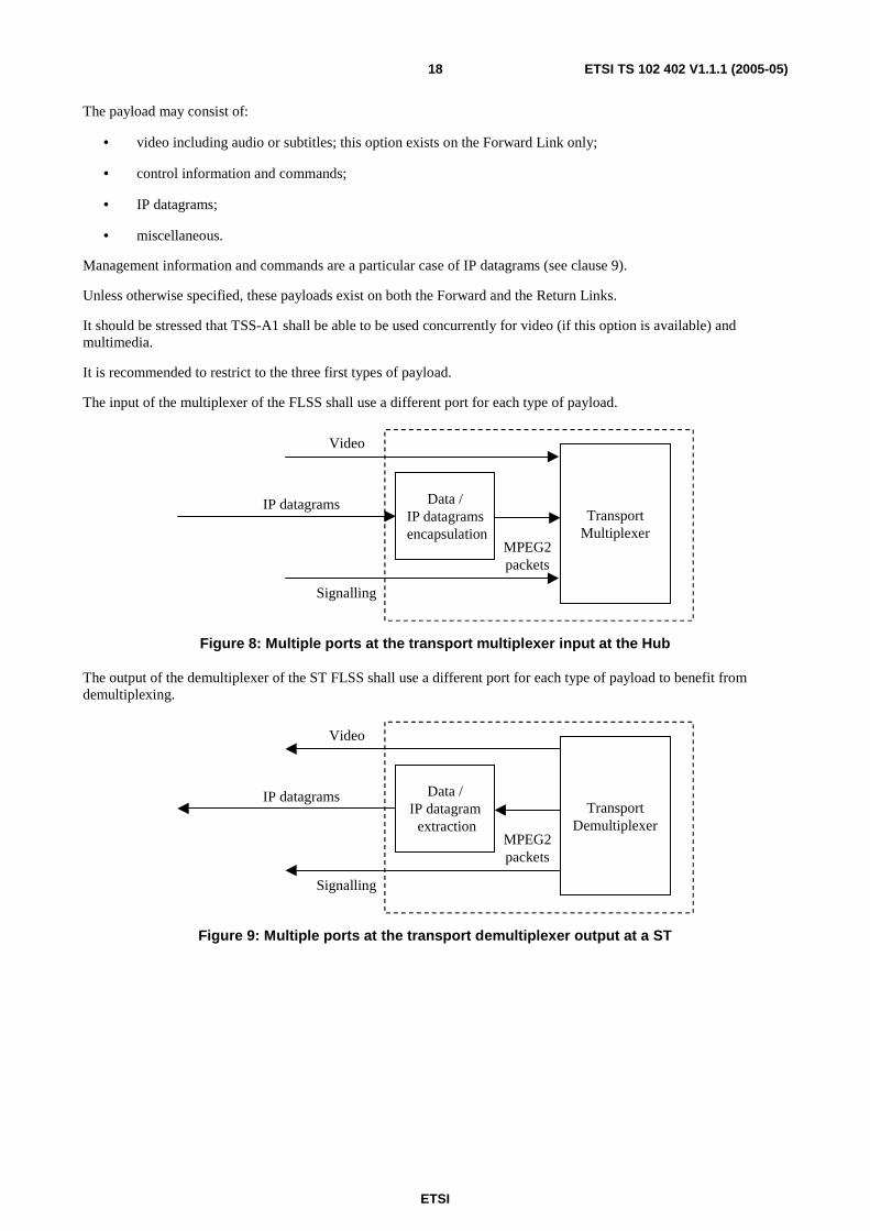
The input of the multiplexer of the FLSS shall use a different port for each type of payload.
Data /IP datagrams
encapsulation
Video
TransportMultiplexer
MPEG2packets
Signalling
IP datagrams
Figure 8: Multiple ports at the transport multiplexer input at the Hub
The output of the demultiplexer of the ST FLSS shall use a different port for each type of payload to benefit from demultiplexing.
Data /IP datagram extraction
Video
TransportDemultiplexer
MPEG2packets
Signalling
IP datagrams
Figure 9: Multiple ports at the transport demultiplexer output at a ST
ETSI
ETSI TS 102 402 V1.1.1 (2005-05) 19
6.3 MAC and Data Link layer
6.3.1 Forward link
6.3.1.1 Multi Protocol Encapsulation
The MultiProtocol Encapsulation (MPE) [7], [14] provides a mechanism for transporting data network protocols on top of the MPEG2-TS in DVB networks by emulating a LAN. It has been optimized for carriage of the Internet Protocol, but can be used for transportation of any other network protocol by using the LLC/SNAP encapsulation. It covers unicast, multicast and broadcast.
The encapsulation allows secure transmission of data by supporting encryption of the packets.
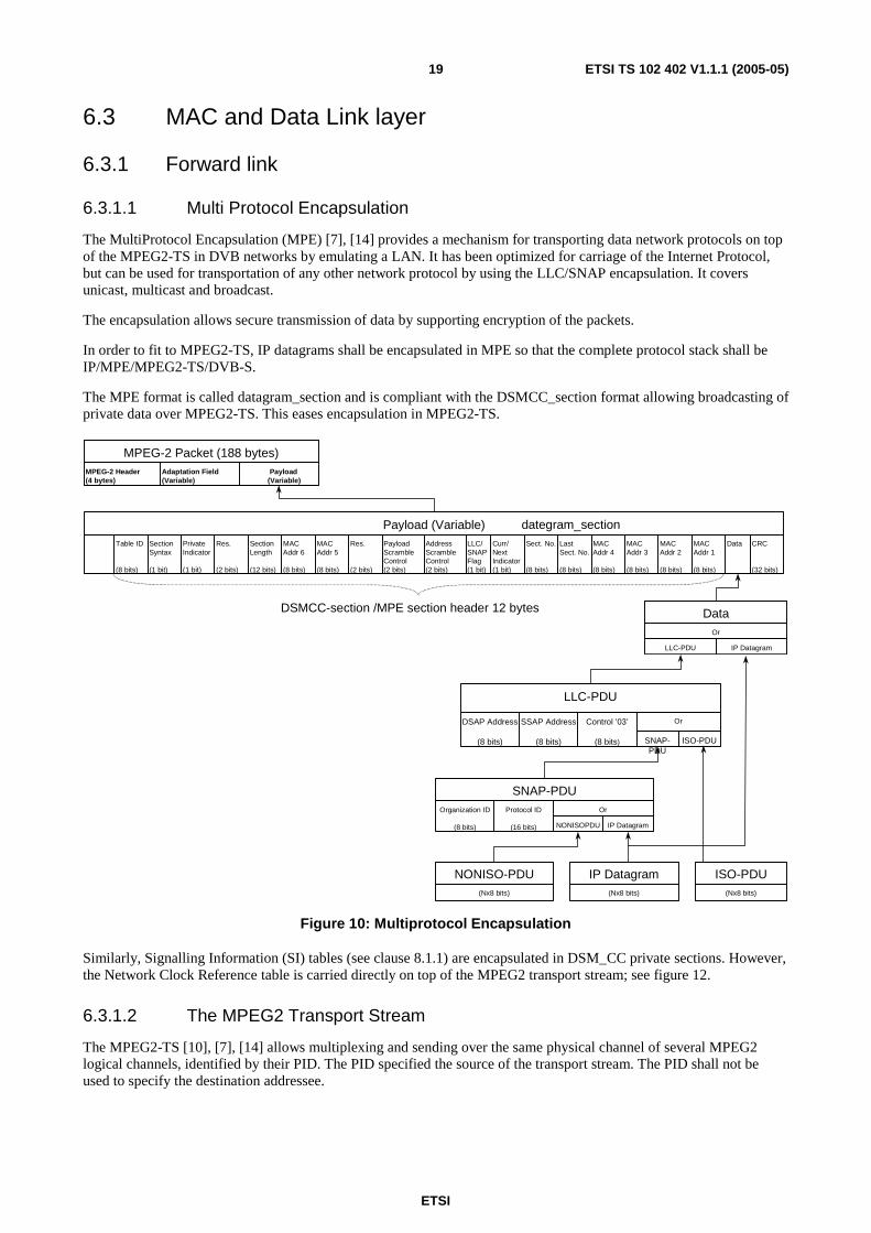
In order to fit to MPEG2-TS, IP datagrams shall be encapsulated in MPE so that the complete protocol stack shall be IP/MPE/MPEG2-TS/DVB-S.
The MPE format is called datagram_section and is compliant with the DSMCC_section format allowing broadcasting of private data over MPEG2-TS. This eases encapsulation in MPEG2-TS.
Payload (Variable)
Adaptation Field(Variable)
MPEG-2 Header(4 bytes)
MPEG-2 Packet (188 bytes)
CRC
(32 bits)
DataMACAddr 1
(8 bits)
MACAddr 2
(8 bits)
MACAddr 3
(8 bits)
MACAddr 4
(8 bits)
LastSect. No.
(8 bits)
Sect. No.
(8 bits)
Curr/NextIndicator(1 bit)
LLC/SNAPFlag(1 bit)
AddressScrambleControl(2 bits)
PayloadScrambleControl(2 bits)
Res.
(2 bits)
MACAddr 5
(8 bits)
MACAddr 6
(8 bits)
SectionLength
(12 bits)
Res.
(2 bits)
PrivateIndicator
(1 bit)
SectionSyntax
(1 bit)
Table ID
(8 bits)
PointerField
(8 bits)
Payload (Variable)
Or
IP DatagramLLC-PDU
Data
ISO-PDUSNAP-PDU
OrControl ’03’
(8 bits)
SSAP Address
(8 bits)
DSAP Address
(8 bits)
LLC-PDU
IP DatagramNONISOPDU
OrProtocol ID
(16 bits)
Organization ID
(8 bits)
SNAP-PDU
(Nx8 bits)
IP Datagram(Nx8 bits)
ISO-PDU(Nx8 bits)
NONISO-PDU
DSMCC-section /MPE section header 12 bytes
dategram_section
Figure 10: Multiprotocol Encapsulation
Similarly, Signalling Information (SI) tables (see clause 8.1.1) are encapsulated in DSM_CC private sections. However, the Network Clock Reference table is carried directly on top of the MPEG2 transport stream; see figure 12.
6.3.1.2 The MPEG2 Transport Stream
The MPEG2-TS [10], [7], [14] allows multiplexing and sending over the same physical channel of several MPEG2 logical channels, identified by their PID. The PID specified the source of the transport stream. The PID shall not be used to specify the destination addressee.
ETSI
ETSI TS 102 402 V1.1.1 (2005-05) 20
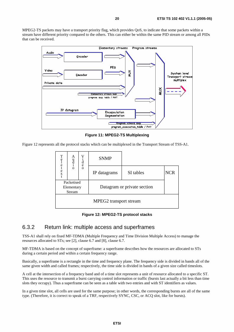
MPEG2-TS packets may have a transport priority flag, which provides QoS, to indicate that some packets within a stream have different priority compared to the others. This can either be within the same PID stream or among all PIDs that can be received.
MUX
MUX
IP datagramEncapsulationSegmentation
Encoder
Encoder
Audio
Video
Private data
PES
System levelTransport stream
multiplex
Elementary stream map
program_map_table / PMT
Elementary streams Program streams
program_association_table / PAT
Program stream map
Figure 11: MPEG2-TS Multiplexing
Figure 12 represents all the protocol stacks which can be multiplexed in the Transport Stream of TSS-A1.
SNMP
IP datagrams SI tables NCR
Datagram or private sectionPacketisedElementary
Stream
Teletext
Audio
Video
MPEG2 transport stream
Figure 12: MPEG2-TS protocol stacks
6.3.2 Return link: multiple access and superframes
TSS-A1 shall rely on fixed MF-TDMA (Multiple Frequency and Time Division Multiple Access) to manage the resources allocated to STs; see [2], clause 6.7 and [8], clause 6.7.
MF-TDMA is based on the concept of superframe: a superframe describes how the resources are allocated to STs during a certain period and within a certain frequency range.
Basically, a superframe is a rectangle in the time and frequency plane. The frequency side is divided in bands all of the same given width and called frames; respectively, the time side is divided in bands of a given size called timeslots.
A cell at the intersection of a frequency band and of a time slot represents a unit of resource allocated to a specific ST. This uses the resource to transmit a burst carrying control information or traffic (bursts last actually a bit less than time slots they occupy). Thus a superframe can be seen as a table with two entries and with ST identifiers as values.
In a given time slot, all cells are used for the same purpose; in other words, the corresponding bursts are all of the same type. (Therefore, it is correct to speak of a TRF, respectively SYNC, CSC, or ACQ slot, like for bursts).
ETSI
ETSI TS 102 402 V1.1.1 (2005-05) 21
Traffic slots shall be all of the same duration sized to carry one or two ATM cells as per [15]. The fixed size of cells conveying traffic characterizes fixed MF-TDMA.
Typical values for superframe and slots duration are as follows:
• CSC and ACQ slots have the same duration as TRF slots; SYNC slots have half the duration of TRF slots; SYNC slots come by pair so that the total time of time slots fit to the frame duration;
• the superframe total duration should be 26,5 ms; the total bandwidth is up to the Satellite sub-network Operator.
NOTE: Other values of superframe duration may be used.
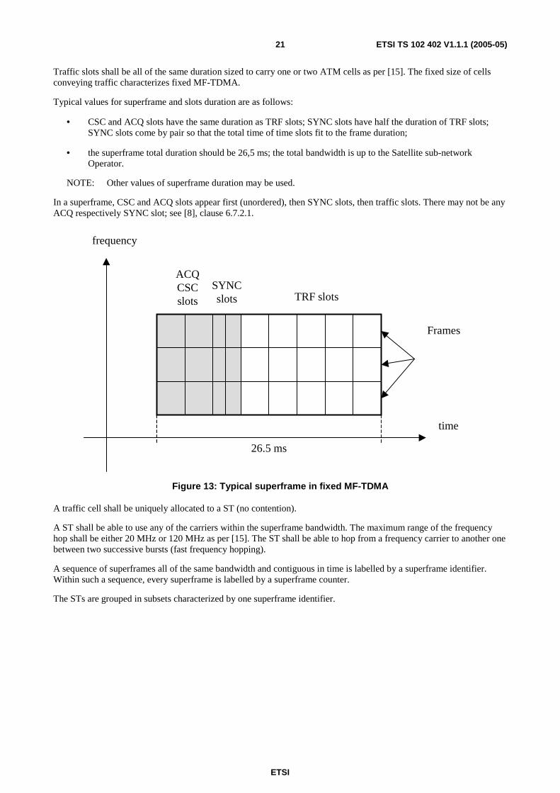
In a superframe, CSC and ACQ slots appear first (unordered), then SYNC slots, then traffic slots. There may not be any ACQ respectively SYNC slot; see [8], clause 6.7.2.1.
time
frequency
ACQCSCslots
Frames
SYNCslots TRF slots
26.5 ms
Figure 13: Typical superframe in fixed MF-TDMA
A traffic cell shall be uniquely allocated to a ST (no contention).
A ST shall be able to use any of the carriers within the superframe bandwidth. The maximum range of the frequency hop shall be either 20 MHz or 120 MHz as per [15]. The ST shall be able to hop from a frequency carrier to another one between two successive bursts (fast frequency hopping).
A sequence of superframes all of the same bandwidth and contiguous in time is labelled by a superframe identifier. Within such a sequence, every superframe is labelled by a superframe counter.
The STs are grouped in subsets characterized by one superframe identifier.

ETSI
ETSI TS 102 402 V1.1.1 (2005-05) 22
Superframe Identifier 3
Superframe Identifier 2
Superframe Identifier 1
Figure 14: Typical usage of Superframe Identifiers
The NCC periodically (every frame duration) computes superframes and transmits a number of tables to STs to indicate them the superframe identifier and counter, the superframe composition (types of time slots), the distribution of resource to STs and the coding parameters which are subject to change from one superframe to the other. The set of tables used are described in clause 8.1.
6.4 Physical layer
6.4.1 Forward link
The signal shall comply with DVB-S norm as defined in [3]. This reference fully specifies the processes of randomization, outer coding, interleaving, inner coding, puncturing, baseband shaping and finally modulation leaving little room for option; however when options are possible (e.g. as for the coding rate) all these shall be available in TSS-A1.
6.4.2 Return link
6.4.2.1 General
The signal shall comply with DVB-RCS norm as defined in [2], clause 6 and [8], clause 6. Which options shall be retained in TSS-A1 is defined below.
ETSI
ETSI TS 102 402 V1.1.1 (2005-05) 23
6.4.2.2 Return link emission at the STs: burst format
Bursts shall start with a preamble for detection. They may be followed by a guard time to decrease transmitted power and compensate for timing errors. See [2], clause 6.2.
Burst shall be encoded save bursts of the ACQ type (see clause 8.2.1). Following SatLabs System Recommendations [15], TSS-A1 shall support turbo coding with default parameters defined in [2], clause 6.4.4.
In addition, TSS-A1 may support:
• a combination of outer coding with a Reed-Solomon code and inner coding with a convolutional code;
• detection by means of Cyclic Redundancy Check.
The codes to be used are further specified in [2], clause 6.4 and the recommendations for using or bypassing some stages in the coding process in [8], clause 6.4.
7 Profile in the Data plane By definition, the data plane is the set of specifications pertaining to the transport of IP datagrams. The transport of Video (and associated payloads) is not addressed in further detail in the present document.
7.1 Forward Link: IP over DVB-S
7.1.1 Useful bit rate
The bit rate shall be configurable. The recommended range is from 1 Mbps to 50 Mbps or greater.
7.1.2 Mac and Data link layer
7.1.2.1 Addressing
The MAC address of the ST shall be located in the datagram_section. It is 48-bit long and split in two parts. The locations of the MAC address segments are specified in [6].
The MAC address may be scrambled; scrambling is controlled by means of two bits, "00" indicating that there is no scrambling. Scrambling is fully specified in [6].
In the Cell Analyser at the ST, MPE packets shall be either silently discarded if their MAC address is not that of the ST or else disassembled and transmitted to the Gateway.
7.2 Return Link: IP over DVB-RCS
7.2.1 Useful bit rate
The bit rate shall be configurable. The recommended range is 256 kbps to 2 Mbps or greater.
7.2.2 Data Link layer: ATM format
IP datagrams shall be encapsulated in ATM cells by means of the ATM Adaptation Layer 5 (AAL5), according to the specifications of [16]; the resulting protocol stack is IP/AAL5/ATM. The point in AAL5 is that it allows data to fit to a fixed ATM cell format by stuffing and thus avoids segmentation and reassembly of ATM cells. The length of ATM cells shall be 53 bytes.
An ST shall thus establish Virtual Circuits (VCs) with the Hub. The encapsulation mechanism shall be VC based multiplexing. It allows multiplexing of several VCs hence of the different types of data stream formats (not only IP datagrams) the VCs may carry.

ETSI
ETSI TS 102 402 V1.1.1 (2005-05) 24
7.2.3 Physical layer: traffic bursts
TSS-A1 shall use Traffic (TRF) bursts for carrying useful data on the return link. A TRF burst contains exactly one or two 53 bytes long ATM cell as a payload. A Satellite Access Control (SAC) field is appended to the beginning of the ATM cell(s) to transport MAC messages. The SAC field shall be two bytes long; for a two cells payload, it is recommended that TSS-A1 also support a 5 bytes length as per [15]. Beside, TRF bursts meet the general specifications of clause 6.4.2.2.
ATM cell53 bytes
2 bytes
SAC field
Encoded DataPreamble
ATM TRF burst
Figure 15: Insertion of an ATM cell in a TRF burst
8 Profile in the Control Plane The Control Plane is the set of specifications pertaining to signalling and associated functions: synchronization, link establishment, resources requests and allocations.
8.1 Signalling on the Forward Link
8.1.1 General Information: Service Information tables
The Service Information (SI) in MPEG2 provides information which enables automatic configuration of the receiver and to demultiplex and decode the various streams in the multiplex. SI data are structured in tables encapsulated in DSM_CC private sections, according to MPE, and inserted in the payload of MPEG2 packets (see clause 6.3.1). Private sections carrying SI tables are characterized by a specific PID. General concepts on SI can be found in [9].
The SI tables TSS-A1 uses can be classified in two categories:
• Program Service Information (PSI) tables: the Program Association Table (PAT) and the Program Map Table (PMT); these tables enable to demultiplex the forward link signal and to reconstruct each individual stream (see [9]);
• tables specific to DVB-RCS [2], clause 8.3: Superframe Composition Table (SCT), Time slot Composition Table (TCT), Satellite Position Table (SPT), Frame Composition Table (FCT), Terminal Burst Time Plan (TBTP), Correction Message Table (CMT).
ETSI
ETSI TS 102 402 V1.1.1 (2005-05) 25
8.1.2 Terminal Information Message
The TIM message is sent by the NCC either to an individual ST addressed by its MAC address (unicast message) or broadcast to all STs using a reserved broadcast MAC address and contains static or quasi static information about the forward link such as configuration.
This message may also be used to facilitate the handing over of an ST to a different group or network group or network or to switch a group of STs to a different forward link signalling service on another MPEG2-TS for example. This message is sent in a DSM_CC private data section.
8.1.3 Network Clock Reference
The NCR carries the information required for system synchronization; see clause 8.3.1. The NCR is distributed with a specific PID within the MPEG2 Transport Stream that carries the forward link. The concept of NCR is equivalent to the concept of PCR in [10] and its distribution follows the same mechanism.
8.2 Signalling on the Return Link
8.2.1 Burst types and their format
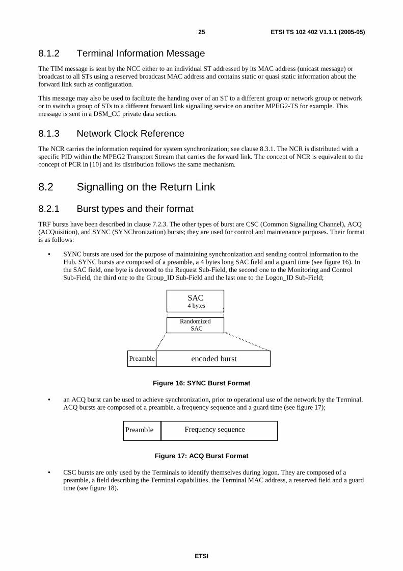
TRF bursts have been described in clause 7.2.3. The other types of burst are CSC (Common Signalling Channel), ACQ (ACQuisition), and SYNC (SYNChronization) bursts; they are used for control and maintenance purposes. Their format is as follows:
• SYNC bursts are used for the purpose of maintaining synchronization and sending control information to the Hub. SYNC bursts are composed of a preamble, a 4 bytes long SAC field and a guard time (see figure 16). In the SAC field, one byte is devoted to the Request Sub-Field, the second one to the Monitoring and Control Sub-Field, the third one to the Group_ID Sub-Field and the last one to the Logon_ID Sub-Field;
SAC
encoded burstPreamble
RandomizedSAC
4 bytes
Figure 16: SYNC Burst Format
• an ACQ burst can be used to achieve synchronization, prior to operational use of the network by the Terminal. ACQ bursts are composed of a preamble, a frequency sequence and a guard time (see figure 17);
Frequency sequencePreamble
Figure 17: ACQ Burst Format
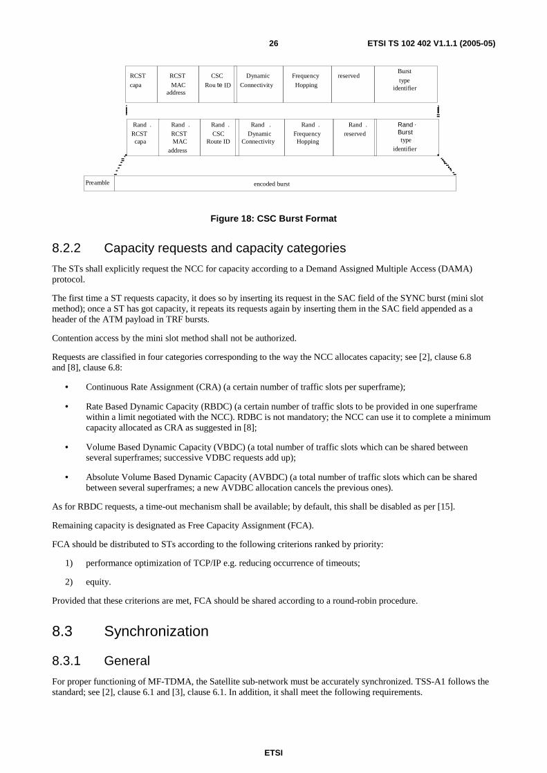
• CSC bursts are only used by the Terminals to identify themselves during logon. They are composed of a preamble, a field describing the Terminal capabilities, the Terminal MAC address, a reserved field and a guard time (see figure 18).
ETSI
ETSI TS 102 402 V1.1.1 (2005-05) 26
encoded burstPreamble
Rand .RCSTcapa
Rand .RCSTMAC
address
RCST
capa
RCST
MACaddress
Rand .reserved
reservedBurst
typeidentifier
.Bursttype
identifier
Rand .CSC
Route ID
CSC
Rou te ID
Rand .Dynamic
Connectivity
Dynamic
Connectivity
Rand .FrequencyHopping
Frequency
Hopping
Rand
Figure 18: CSC Burst Format
8.2.2 Capacity requests and capacity categories
The STs shall explicitly request the NCC for capacity according to a Demand Assigned Multiple Access (DAMA) protocol.
The first time a ST requests capacity, it does so by inserting its request in the SAC field of the SYNC burst (mini slot method); once a ST has got capacity, it repeats its requests again by inserting them in the SAC field appended as a header of the ATM payload in TRF bursts.
Contention access by the mini slot method shall not be authorized.
Requests are classified in four categories corresponding to the way the NCC allocates capacity; see [2], clause 6.8 and [8], clause 6.8:
• Continuous Rate Assignment (CRA) (a certain number of traffic slots per superframe);
• Rate Based Dynamic Capacity (RBDC) (a certain number of traffic slots to be provided in one superframe within a limit negotiated with the NCC). RDBC is not mandatory; the NCC can use it to complete a minimum capacity allocated as CRA as suggested in [8];
• Volume Based Dynamic Capacity (VBDC) (a total number of traffic slots which can be shared between several superframes; successive VDBC requests add up);
• Absolute Volume Based Dynamic Capacity (AVBDC) (a total number of traffic slots which can be shared between several superframes; a new AVDBC allocation cancels the previous ones).
As for RBDC requests, a time-out mechanism shall be available; by default, this shall be disabled as per [15].
Remaining capacity is designated as Free Capacity Assignment (FCA).
FCA should be distributed to STs according to the following criterions ranked by priority:
1) performance optimization of TCP/IP e.g. reducing occurrence of timeouts;
2) equity.
Provided that these criterions are met, FCA should be shared according to a round-robin procedure.
8.3 Synchronization
8.3.1 General
For proper functioning of MF-TDMA, the Satellite sub-network must be accurately synchronized. TSS-A1 follows the standard; see [2], clause 6.1 and [3], clause 6.1. In addition, it shall meet the following requirements.
ETSI
ETSI TS 102 402 V1.1.1 (2005-05) 27
The NCC shall provide the Satellite sub-network with a common value for the absolute time, a common symbol clock for symbol emission and a common frequency reference for generating carriers. It shall do so by broadcasting a Network Clock Reference (NCR) (see clause 8.1.3). The NCC may acquire this Reference in various ways such as consulting GPS.
The NCC shall compensate for the Doppler shift introduced on the links between itself and the Satellite.
The NCC shall not compensate for the Doppler shift introduced on the links between the Satellite and the STs; this is left to the STs (see next clause).
Each ST shall correct the NCR by subtracting the expected Forward Link transmission delay. The transmission delay can be interpreted in two different manners depending whether:
• the hub serves as the reference point for the NCR; then the transmission delay equals the time the signal takes to travel on the whole Forward Link from the hub to the ST; or
• the satellite serves as the reference point for the NCR; then the transmission delay equals the time the signal takes to travel from the satellite to the ST on the Forward Link.
As for carrier generation, each ST shall use its own oscillator which shall be tuned by means of the NCR method.
The STs shall retrieve the centre frequency, the start time and the duration of their transmit bursts by examining the TBTP. The actual start time of any transmit burst at a given ST is calculated by subtracting the expected Return Link transmission delay from the start time indicated in the TBTP.
In TSS-A1, due to fixed MF-TDMA, the Superframe Composition is fixed, the Frame Composition is fixed and the duration of the transmit bursts is fixed. Therefore there is no need to use Superframe Composition Tables nor Frame Composition Tables in principle. However the Hub shall retransmit the tables at regular intervals in order to inform newcomers of the current settings and to refresh the relevant items of information (set of frequency carriers to be used, traffic slot duration, etc.). The Time-slot Composition Table remains useful where as it carries information affecting the formatting of the traffic slots.
8.3.2 Synchronization procedures
8.3.2.1 Overall events sequencing
Prior to attempt to enter the Satellite sub-network, a ST shall achieve the Initial synchronization procedure by which it acquires all necessary information from the Hub. The entry is then achieved through the following four phases:
- Logon procedure: the ST requests initial access to the Network and gets initial logon information from the Network (or alternatively the logon request may be rejected by the Network). The ST sends its request in a CSC timeslot using Slotted Aloha random access. Once the login is successful, the ST switches to the MF-TDMA normal access mode; for the remaining of the synchronization procedure, it uses the signalling bursts allocated to it.
- Acquisition coarse synchronization procedure: the ST improves its physical synchronization (frequency, time, and power adjustments).
- Fine synchronization procedure: the ST completes its physical synchronization. The ST is now able to request some capacity by means of the minislot method.
- Synchronization maintenance procedure: the ST maintains its physical synchronization during the entire session.
Unless described below, the procedures are as described in the standard [2], clause 7.
ETSI
ETSI TS 102 402 V1.1.1 (2005-05) 28
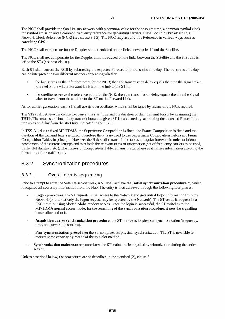
8.3.2.2 Logon procedure
TSS-A1 logon procedure is enhanced with respect to the standard procedure [2], clause 7 by the additional steps shown
in the shaded cells in the flow chart below:
CSC Process
Wait randomisedTinitial
AbnormalLogon ?
Choose CSC slotat random andTransmit logon
message
Replywithin Tto
?
Yes
No
Authenticated?
ACQ/SYNCNo
Yes
Yes
Reason =Busy?
NoYes
No
CSCmaxtries
?
No
Wait Tback_off_n Fault Exit
YesWait randomised
Tresend
Toomany back-off
retries?
YesNo
Figure 19: Logon procedure flowchart
These additional steps are included to handle abnormal logon, user authentication, and CSC repeated retry. The condition of abnormal logon can occur when for example the Forward Link has gone down. After this occurs all the STs in the Satellite sub-network will attempt to log back on. The enhanced procedure automatically regulates the re-entry of the STs by applying a randomized delay.
The step to authenticate the STs is added to explicitly show that this is required before a ST can proceed with the synchronization procedures. The step referred to above as CSC repeated retry is added to allow a ST to automatically, after a randomized delay, restart the login procedure again after it has failed to get in, in its first CSC retry loop.
8.3.2.3 Enhanced coarse synchronization procedure
This clause describes an enhanced coarse synchronization procedure which enables reduction in the login time of about 3 s. Though the standard procedure is compliant with TSS-A1, it is recommended to adopt the enhanced procedure.
At the beginning of the coarse synchronization stage, the ST shall successively:
1) retrieve the burst correction from TIM;
2) correct the burst position;
3) if the burst position is within the range required then the ST shall jump to the fine synchronization stage.
The corresponding flowchart is represented below where the new steps are in the shaded cells.

ETSI
ETSI TS 102 402 V1.1.1 (2005-05) 29
Retrieve SYNC and ACQ slot assignmentsfrom TIM
Ready to startcoarse acquisition
phase
Ready to start FineSynchronisation phase
Max. tries exceeded ormax # ACQs?
Return to start ofInitial Access phase
Receive BurstCorrection
Yes
Reply receivedin time?
No
Yes
Transmit ACQ Burst
Correct BurstPosition
No
Burst correctionneeded ?
Yes
No
Max # ACQs reached?
No
Return to start ofInitial Access phase
Yes
Retrieve Burst Correction from TIM
Correct Burst Position
Burst Correction BeyondLimit Required ?
Yes
No
Figure 20: Enhanced coarse synchronization procedure
9 Management
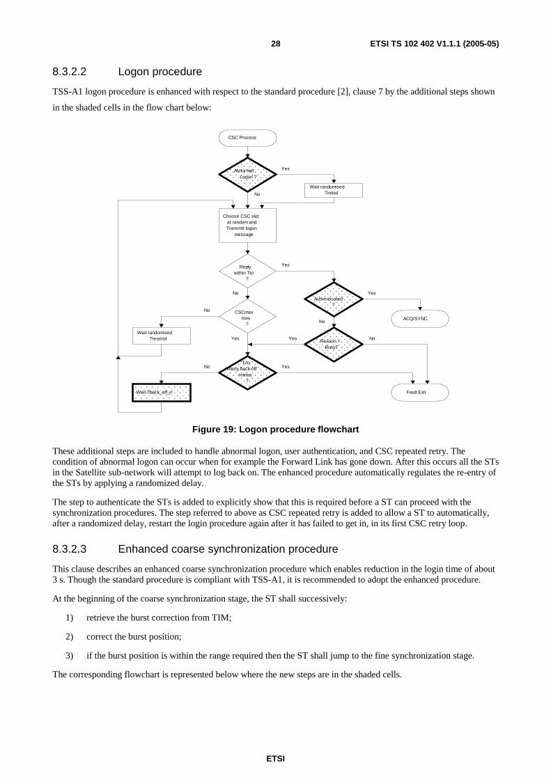
9.1 General concepts and features Management is the set of functions enabling to assess and possibly modify the level of performance of each sub-system of the Hub or each ST. These functions can be separated in five categories: fault management, configuration management, performance management, security management and accounting.
Though management is not mandatory in DVB-RCS Satellite sub-networks in general, TSS-A1 shall offer management functions. TSS-A1 management shall comply with the specifications of [8], clause 8.6.
One of the interest to have an IP based network is the capability to manage the networks according to standards discussed mainly at the IETF: Management Information shall comply with the general principles set forth in [13].
9.2 Specific vs. common functions Some functions are specific to the Hub i.e. they enable managing certain of the Hub's sub-systems; some other are specific to the ST; the remaining ones involve information and sub-systems which can be located either at one end or the other of the Satellite link.
The following figure clarifies the situation.
ETSI
ETSI TS 102 402 V1.1.1 (2005-05) 30
ST Provisioning
Fwd & Rtn pathcapacity config.
SP ResourcesManagement
ST ServicesManagement
ST ProfileManagement
ST Status update
ST Status historiccollection
Alarm & StatusManagement
MAP Management
IPE RedundancySwitch configuration
DVB tables handling
IP Encapsulatorconfiguration
Window Template forSNMP based configuration
Manage the NEembedded software
Apply commandto several equipment
Wizard for complexconfiguration operations
Discover themanaged equipment
MIB Browser
PerformanceManagement
Security &Application utilities
Hub specificST specific
ST managementfunctions
Hub managementfunctions
Common
Figure 21: Repartition of management functions
9.3 Protocol The management logic and the format of the management messages shall comply with Simple Network Management Protocol version 2 (SNMP v2) [11]. SNMP is the most usual way in which network management applications can download respectively upload data from respectively to a MIB.
SNMP is a protocol above IP; then management messages and commands are carried according to the rules pertaining to the transport of IP. However SNMP messages on the Return Link should use different Permanent Virtual Channels (PVCs) than user traffic; moreover, when it is in the Operations, Administration, Maintenance (OAM) active status, a ST is able to send SNMP messages while it is not able to send traffic.
NOTE: While it is an option that STs support SNMP according to [8] and [15], it is mandatory in TSS-A1.
9.4 Management Information Bases The Hub and the STs shall implement two different Management Information Bases (MIB) addressing two different sets of functions and devices whose pattern is defined by the relevant authority:
NOTE 1: While the MIBs are optional in [8] and [15] they are mandatory in TSS-A1.
• MIB-II for TCP/IP functions. The definition of this MIB is under the responsibility of IETF and is described in [12].
• Private Enterprise RCST MIB. The definition of this MIB is under the responsibility of European Broadcasting Union and is described in [8], clause 8.6.
NOTE 2: Additional MIBs may also be used.
The groups and objects of the latter MIB are exhaustively described in [8], annex F.
ETSI
ETSI TS 102 402 V1.1.1 (2005-05) 31
MIBs compliant with these patterns shall be implemented in the Hub and in the STs as well. The set of objects encompassed by the union of these MIBs is referred to as "the MIB" in the following.
9.5 ST configuration A ST with SNMP capability shall have additional states (or statuses) with respect to non SNMP capable STs. The state has one the following values: idle, initialized, hold, OAM active, fully active, fault; see [8], clause 8.6.3. However, in TSS-A1, the hub shall be capable of working with terminals that either differentiate the states OAM active and the fully active or do not differentiate them.
A ST signals its SNMP capability by the SNMP field of the ST Capability field carried in the CSC burst that is sent during logon. An NCC that wants to dialog with a ST either in the OAM Active status or the fully active status for access control shall reply with a TIM that contains a Network Layer Info Descriptor described in [8], clause 8.6.3.
A ST MIB shall be allocated a specific IP address different from the one used for carrying traffic and referred to as the OAM IP address.
9.6 Management and Control As described in [2], clause 8.4.2, SNMP commands ensure interoperability between the NCC and the STs. The NCC obtains the current configuration parameter values from the ST MIB, in order to request transmission characteristics required for the ST. The NCC and the STs exchange SNMP messages, such as installation procedures implementation, software upgrades, authorization or prohibition of transmission, individual/group control and traffic forward link assignments, ST status enquiries, and ST or NCC requests to leave the network.
Maintaining ST profiles up-to-date is the job of the NMS.
10 Security Radio communications are more than any other ones subject to security threats (eavesdropping, jamming). An overview of the threats and of possible countermeasures is made in [17].
The only security requirements in TSS-A1 regard the protection of resource (satellite capacity). Integrity or privacy of data/reserved access are optional.
10.1 Data protection
10.1.1 Upper layers mechanisms
In this clause, it is assumed that the payload of MPEG2 packets in the forward link respectively of the ATM cells in the return link consists in IP datagrams (see clause 6.2).
By upper layers, it is meant layer 3 and above. A typical layer 3 security mechanism is IPSec [20] which can work either in tunnel mode or in transport mode. IPSec requires some adaptations to perform efficiently over satellite; this issue is discussed in [17].
TSS-A1 shall be able to support upper layers security mechanisms. It is up to the Satellite sub-network operator or to the service provider to provide and enable these mechanisms.

ETSI
ETSI TS 102 402 V1.1.1 (2005-05) 32
10.1.2 Forward link: DVB-S Conditional Access
In this clause, it is assumed that the payload of MPEG2 packets consists of video; it is recalled that this is optional (see clause 6.2).
Conditional Access (CA) [10] is a service that allows service providers (chiefly broadcasters) to restrict certain programming products to certain viewers. The CA does this by scrambling [18] the service providers' programs. Consequently, the programs must be decrypted at the receiving end before they can be decoded for viewing. CA offers capabilities such as Pay-Per-View.
CA belongs to the baseline of MPEG2/DVB-S; therefore, as far as it supports video, TSS-A1 shall support CA. It is up to the Satellite sub-network operator or to the service provider to provide and enable this mechanism.
10.2 Protection of resource The NCC shall authenticate the STs. Authentication takes place at logon (see clause 8.3.2.2).
In combination with authentication, the NCC and the NMS account for the resource consumed by any ST for the calculation of which amount of resource it may request. This can be seen as a protection measure.
These functions are performed at level 2 and must not be confused with the AAA functions of ISPs.
Other functions would be desirable: non-repudiation, ciphering (or scrambling) of signalling, etc.
10.3 Miscellaneous TSS-A1 shall provide terminal barring: at any moment the Satellite sub-network Operator can logoff a ST from the network.

ETSI
ETSI TS 102 402 V1.1.1 (2005-05) 33
Annex A (informative): Bibliography
• ETSI EN 301 192 (V1.3.1): "Digital Video Broadcasting (DVB); DVB specification for data broadcasting".
• ETSI TR 100 815: "Digital Video Broadcasting (DVB); Guidelines for the handling of Asynchronous Transfer Mode (ATM) signals in DVB systems".
• ETSI TS 102 292: "Satellite Earth Stations and Systems (SES); Broadband Satellite Multimedia (BSM) services and architectures; Functional architecture for IP interworking with BSM networks".

ETSI
ETSI TS 102 402 V1.1.1 (2005-05) 34
History
Document history
V1.1.1 May 2005 Publication


![TS 102 721-1 - V1.1.1 - Satellite Earth Stations and …...ETSI 7 ETSI TS 102 721-1 V1.1.1 (2011-12) [i.5] ETSI EN 302 574-3: "Satellite Earth Stations and Systems (SES); Harmonized](https://static.fdocuments.in/doc/165x107/5e8cdc186c7edd425f35bb14/ts-102-721-1-v111-satellite-earth-stations-and-etsi-7-etsi-ts-102-721-1.jpg)