TS 100 916 - V07.04.00 - Digital cellular ... 01, 2010 · AT command set for GSM Mobile Equipment...
126
ETSI TS 100 916 V7.4.0 (1999-11) Technical Specification Digital cellular telecommunications system (Phase 2+); AT command set for GSM Mobile Equipment (ME) (GSM 07.07 version 7.4.0 Release 1998) GLOBAL SYSTEM FOR MOBILE COMMUNICATIONS R
Transcript of TS 100 916 - V07.04.00 - Digital cellular ... 01, 2010 · AT command set for GSM Mobile Equipment...

ETSI TS 100 916 V7.4.0 (1999-11)Technical Specification
Digital cellular telecommunications system (Phase 2+);AT command set for GSM Mobile Equipment (ME)
(GSM 07.07 version 7.4.0 Release 1998)
GLOBAL SYSTEM FORMOBILE COMMUNICATIONS
R
ETSI
ETSI TS 100 916 V7.4.0 (1999-11)2(GSM 07.07 version 7.4.0 Release 1998)
ReferenceRTS/SMG-040707Q7R1 (8hc03jc3.PDF)
KeywordsDigital cellular telecommunications system,
Global System for Mobile communications (GSM)
ETSI
Postal addressF-06921 Sophia Antipolis Cedex - FRANCE
Office address650 Route des Lucioles - Sophia Antipolis
Valbonne - FRANCETel.: +33 4 92 94 42 00 Fax: +33 4 93 65 47 16
Siret N° 348 623 562 00017 - NAF 742 CAssociation à but non lucratif enregistrée à laSous-Préfecture de Grasse (06) N° 7803/88
Individual copies of this ETSI deliverablecan be downloaded from
http://www.etsi.orgIf you find errors in the present document, send your
comment to: [email protected]
Important notice
This ETSI deliverable may be made available in more than one electronic version or in print. In any case of existing orperceived difference in contents between such versions, the reference version is the Portable Document Format (PDF).In case of dispute, the reference should be the printing on ETSI printers of the PDF version kept on a specific network
drive within ETSI Secretariat.
Copyright Notification
No part may be reproduced except as authorized by written permission.The copyright and the foregoing restriction extend to reproduction in all media.
© European Telecommunications Standards Institute 1999.All rights reserved.

ETSI
ETSI TS 100 916 V7.4.0 (1999-11)3(GSM 07.07 version 7.4.0 Release 1998)
Contents
Intellectual Property Rights................................................................................................................................7
Foreword.............................................................................................................................................................7
Introduction ........................................................................................................................................................7
1 Scope ........................................................................................................................................................8
2 References ................................................................................................................................................8
3 Abbreviations and definitions ................................................................................................................103.1 Abbreviations ...................................................................................................................................................103.2 Definitions ........................................................................................................................................................11
4 AT command syntax ..............................................................................................................................114.1 Command line ..................................................................................................................................................124.2 Information responses and result codes ............................................................................................................124.3 ITU-T V.25ter [14] TE-TA interface commands .............................................................................................13
5 General commands.................................................................................................................................135.1 Request manufacturer identification +CGMI ...................................................................................................135.2 Request model identification +CGMM ............................................................................................................145.3 Request revision identification +CGMR ..........................................................................................................145.4 Request product serial number identification +CGSN .....................................................................................155.5 Select TE character set +CSCS ........................................................................................................................155.6 Request international mobile subscriber identity +CIMI..................................................................................165.7 Multiplexing mode +CMUX $(MUX MS-TE)$..............................................................................................165.8 ITU-T V.25ter [14] generic TA control commands .........................................................................................185.9 PCCA STD-101 [17] select wireless network +WS46 .....................................................................................185.10 Informative examples .......................................................................................................................................19
6 Call control commands and methods .....................................................................................................206.1 Select type of address +CSTA..........................................................................................................................206.2 ITU-T V.25ter [14] dial command D ...............................................................................................................206.3 Direct dialling from phonebooks ......................................................................................................................216.4 Call mode +CMOD ..........................................................................................................................................226.5 Hangup call +CHUP.........................................................................................................................................226.6 Alternating mode call control method ..............................................................................................................236.7 Select bearer service type +CBST....................................................................................................................256.8 Radio link protocol +CRLP..............................................................................................................................266.9 Service reporting control +CR..........................................................................................................................276.10 Extended error report +CEER ..........................................................................................................................286.11 Cellular result codes +CRC ..............................................................................................................................286.12 HSCSD device parameters +CHSD..................................................................................................................296.13 HSCSD transparent call configuration +CHST ................................................................................................306.14 HSCSD non-transparent call configuration +CHSN.........................................................................................306.15 HSCSD current call parameters +CHSC ..........................................................................................................316.16 HSCSD parameters report +CHSR$(AT R98)$...............................................................................................316.17 HSCSD automatic user initiated upgrading +CHSU$(AT R98)$ ....................................................................326.18 Single numbering scheme +CSNS....................................................................................................................336.19 Voice Hangup Control +CVHU $(AT R97)$ ..................................................................................................336.20 V.120 rate adaption protocol +CV120 .............................................................................................................346.21 ITU-T V.25ter [14] call control commands......................................................................................................366.22 ITU-T V.25ter [14] data compression commands ............................................................................................366.23 Informative examples .......................................................................................................................................36
7 Network service related commands .......................................................................................................377.1 Subscriber number +CNUM.............................................................................................................................377.2 Network registration +CREG ...........................................................................................................................387.3 Operator selection +COPS ...............................................................................................................................39

ETSI
ETSI TS 100 916 V7.4.0 (1999-11)4(GSM 07.07 version 7.4.0 Release 1998)
7.4 Facility lock +CLCK ........................................................................................................................................407.5 Change password +CPWD ...............................................................................................................................427.6 Calling line identification presentation +CLIP .................................................................................................437.7 Calling line identification restriction +CLIR....................................................................................................447.8 Connected line identification presentation +COLP ..........................................................................................447.9 Closed user group +CCUG...............................................................................................................................457.10 Call forwarding number and conditions +CCFC ..............................................................................................467.11 Call waiting +CCWA .......................................................................................................................................477.12 Call related supplementary services +CHLD....................................................................................................497.13 Call deflection +CTFR .....................................................................................................................................497.14 Unstructured supplementary service data +CUSD ...........................................................................................507.15 Advice of Charge +CAOC................................................................................................................................517.16 Supplementary service notifications +CSSN....................................................................................................527.17 List current calls +CLCC..................................................................................................................................537.18 Preferred operator list +CPOL $(AT R97)$ ....................................................................................................557.19 Read operator names +COPN $(AT R97)$ .....................................................................................................557.20 Informative examples .......................................................................................................................................56
8 Mobile Equipment control and status commands ..................................................................................578.1 Phone activity status +CPAS............................................................................................................................588.2 Set phone functionality +CFUN .......................................................................................................................598.3 Enter PIN +CPIN .............................................................................................................................................608.4 Battery charge +CBC .......................................................................................................................................618.5 Signal quality +CSQ.........................................................................................................................................618.6 Mobile Equipment control mode +CMEC........................................................................................................628.7 Keypad control +CKPD ...................................................................................................................................638.8 Display control +CDIS .....................................................................................................................................648.9 Indicator control +CIND ..................................................................................................................................658.10 Mobile Equipment event reporting +CMER ....................................................................................................668.11 Select phonebook memory storage +CPBS ......................................................................................................678.12 Read phonebook entries +CPBR ......................................................................................................................688.13 Find phonebook entries +CPBF .......................................................................................................................698.14 Write phonebook entry +CPBW ......................................................................................................................708.15 Clock +CCLK...................................................................................................................................................708.16 Alarm +CALA..................................................................................................................................................718.17 Generic SIM access +CSIM .............................................................................................................................728.18 Restricted SIM access +CRSM ........................................................................................................................728.19 Secure control command +CSCC.....................................................................................................................738.20 Alert sound mode +CALM $(AT R97)$ ..........................................................................................................748.21 Ringer sound level +CRSL $(AT R97)$ ..........................................................................................................758.22 Vibrator mode +CVIB $(AT R97)$.................................................................................................................758.23 Loudspeaker volume level +CLVL $(AT R97)$ .............................................................................................768.24 Mute control +CMUT $(AT R97)$ .................................................................................................................768.25 Accumulated call meter +CACM $(AT R97)$ ................................................................................................778.26 Accumulated call meter maximum +CAMM $(AT R97)$...............................................................................778.27 Price per unit and currency table +CPUC $(AT R97)$....................................................................................788.28 Call Meter maximum event +CCWE $(AT R98)$...........................................................................................788.29 Power class +CPWC$(AT R98)$ ....................................................................................................................798.30 Set Language +CLAN$(AT R98)$ ..................................................................................................................808.31 Language Event +CLAE$(AT R98)$...............................................................................................................818.32 Set Greeting Text +CSGT$(AT R98)$ ............................................................................................................818.33 Set Voice Mail Number +CSVM$(AT R98)$ .................................................................................................828.34 Ring Melody Playback +CRMP$(AT R98)$ ...................................................................................................838.35 Master Reset +CMAR$(AT R98)$ ..................................................................................................................838.36 List all available AT commands +CLAC$(AT R98)$ .....................................................................................848.37 Informative examples .......................................................................................................................................84
9 Mobile Equipment errors .......................................................................................................................889.1 Report Mobile Equipment error +CMEE .........................................................................................................889.2 Mobile Equipment error result code +CME ERROR.......................................................................................889.2.1 General errors .............................................................................................................................................89

ETSI
ETSI TS 100 916 V7.4.0 (1999-11)5(GSM 07.07 version 7.4.0 Release 1998)
9.2.2 GPRS-related errors....................................................................................................................................909.2.2.1 Errors related to a failure to perform an Attach.....................................................................................909.2.2.2 Errors related to a failure to Activate a Context ....................................................................................919.2.2.3 Other GPRS errors ................................................................................................................................919.3 Informative examples .......................................................................................................................................91
10 Commands for GPRS .............................................................................................................................9110.1 Commands specific to MTs supporting the GPRS ...........................................................................................9210.1.1 Define PDP Context +CGDCONT .............................................................................................................9210.1.2 Quality of Service Profile (Requested) +CGQREQ....................................................................................9410.1.3 Quality of Service Profile (Minimum acceptable) +CGQMIN ...................................................................9510.1.4 GPRS attach or detach +CGATT................................................................................................................9610.1.5 PDP context activate or deactivate +CGACT.............................................................................................9610.1.6 Enter data state +CGDATA........................................................................................................................9810.1.7 Configure local Octet Stream PAD parameters +CGCLOSP .....................................................................9910.1.8 Show PDP address +CGPADDR..............................................................................................................10010.1.9 Automatic response to a network request for PDP context activation +CGAUTO...................................10110.1.10 Manual response to a network request for PDP context activation +CGANS ..........................................10210.1.11 GPRS mobile station class +CGCLASS ...................................................................................................10310.1.12 Configure local triple-X PAD parameters +CGCLPAD ...........................................................................10410.1.13 GPRS event reporting +CGEREP.............................................................................................................10510.1.14 GPRS network registration status +CGREG.............................................................................................10610.1.15 Select service for MO SMS messages +CGSMS......................................................................................10710.2 Modem compatibility commands ...................................................................................................................10810.2.1 MT originated PDP context activation......................................................................................................10810.2.1.1 Request GPRS service 'D' ...................................................................................................................10810.2.2 Network requested PDP context activation...............................................................................................10910.2.2.1 Automatic response to a network request for PDP context activation 'S0' ..........................................10910.2.2.2 Manual acceptance of a network request for PDP context activation 'A' ............................................11010.2.2.3 Manual rejection of a network request for PDP context activation 'H'................................................110
Annex A (normative): Summary of commands from other standards .........................................111
Annex B (normative): Summary of result codes.............................................................................113
Annex C (informative): Commands from TIA IS-101 ......................................................................114
C.1 Introduction ..........................................................................................................................................114
C.2 Commands............................................................................................................................................115C.2.1 Select mode +FCLASS...................................................................................................................................115C.2.2 Buffer threshold setting +VBT .......................................................................................................................115C.2.3 Calling number ID presentation +VCID.........................................................................................................116C.2.4 Receive gain selection +VGR.........................................................................................................................116C.2.5 Transmit gain selection +VGT .......................................................................................................................116C.2.6 Initialise voice parameters +VIP ....................................................................................................................117C.2.7 Inactivity timer +VIT .....................................................................................................................................117C.2.8 Line selection +VLS.......................................................................................................................................117C.2.9 Receive data state +VRX................................................................................................................................119C.2.10 Select compression method +VSM ................................................................................................................119C.2.11 DTMF and tone generation +VTS..................................................................................................................119C.2.12 Tone duration +VTD......................................................................................................................................120C.2.13 Transmit data state +VTX ..............................................................................................................................120

ETSI
ETSI TS 100 916 V7.4.0 (1999-11)6(GSM 07.07 version 7.4.0 Release 1998)
Annex D (informative): Bibliography.................................................................................................121
Annex E (informative): Mobile originated alternating voice/data call example ............................122
Annex F (informative): Mobile terminated voice followed by data call example ..........................123
Annex G (informative): Voice call example .......................................................................................124
Annex H (informative): Change History ............................................................................................125
History ............................................................................................................................................................126

ETSI
ETSI TS 100 916 V7.4.0 (1999-11)7(GSM 07.07 version 7.4.0 Release 1998)
Intellectual Property RightsIPRs essential or potentially essential to the present document may have been declared to ETSI. The informationpertaining to these essential IPRs, if any, is publicly available for ETSI members and non-members, and can be foundin SR 000 314: "Intellectual Property Rights (IPRs); Essential, or potentially Essential, IPRs notified to ETSI in respectof ETSI standards", which is available from the ETSI Secretariat. Latest updates are available on the ETSI Web server(http://www.etsi.org/ipr).
Pursuant to the ETSI IPR Policy, no investigation, including IPR searches, has been carried out by ETSI. No guaranteecan be given as to the existence of other IPRs not referenced in SR 000 314 (or the updates on the ETSI Web server)which are, or may be, or may become, essential to the present document.
ForewordThis Technical Specification (TS) has been produced by the Special Mobile Group (SMG).
The present document specifies the AT command for terminal equipment being used within the digital cellulartelecommunications system.
The contents of the present document is subject to continuing work within SMG and may change following formal SMGapproval. Should SMG modify the contents of the present document, it will be re-released with an identifying change ofrelease date and an increase in version number as follows:
Version 7.x.y
where:
7 indicates Release 1998 of GSM Phase 2+.
x the second digit is incremented for all other types of changes, i.e. technical enhancements, corrections,updates, etc.
y the third digit is incremented when editorial only changes have been incorporated in the specification.
IntroductionThe present document includes some features which are new to this release 98 version GSM 07.07. In order to make iteasier for readers of the present document to find these new features compared to the release 96 version, special markersare used in the text. The following table lists all the new release 97 and release 98 features and the corresponding markerfor each feature.
Feature DesignatorTechnical enhancement and improvement: New AT-commands $(AT R97)$Technical enhancement and improvement: New AT-commands $(AT R98)$Support of Multiplexer according to GSM 07.10 $(MUX MS-TE)$

ETSI
ETSI TS 100 916 V7.4.0 (1999-11)8(GSM 07.07 version 7.4.0 Release 1998)
1 ScopeThe present document specifies a profile of AT commands and recommends that this profile be used for controllingMobile Equipment (ME) functions and GSM network services from a Terminal Equipment (TE) through TerminalAdaptor (TA). The command prefix +C is reserved for Digital Cellular in ITU-T Recommendation V.25ter [14]. Thepresent document has also the syntax details used to construct these extended GSM commands. Commands from ITU-TRecommendation V.25ter [14] and existing digital cellular standards (TIA IS-99 [15] and TIA IS-135 [16]) are usedwhenever applicable. Some of the new commands are defined in such a way that they can be easily applied to ME ofnetworks other than GSM. ITU-T T.31 [11] and T.32 [12] fax AT commands may be used for GSM fax transmissionfrom TE. GSM Short Message Service AT commands are defined in GSM 07.05 [24]. GPRS AT commands are definedin clause 10 of the present document.The present document assumes an abstract architecture comprising a TE (e.g. acomputer) and a ME interfaced by a TA (see figure 1). The span of control of the defined commands should allow tohandle any physical implementation that this abstract architecture may lead to:
- TA, ME and TE as three separate entities;
- TA integrated under the ME cover, and the TE implemented as a separate entity;
- TA integrated under the TE cover, and the ME implemented as a separate entity;
- TA and ME integrated under the TE cover as a single entity.
The commands described in the present document may be observed on the link between the TE and the TA. However,most of the commands retrieve information about the ME, not about the TA.
TE TA MEATcmds
responses
MEcontrol
MEstatus
USER&APPLICATIONS NETWORK
network messages
Figure 1: Setup
Interface between TE and TA is intended to operate over existing serial (ITU-T Recommendation V.24) cables, infraredlink, and all link types with similar behaviour. For correct operation many of the defined commands require eight bitdata and therefore it is recommended that TE-TA link is set to eight bits/ byte mode. (For infrared operationimplementation refer informative references IrDA. For embedding AT commands and data during on-line data staterefer TIA-617/ITU-T V.80.) Interface between TA and ME is dependent on the interface in the ME.
2 ReferencesThe following documents contain provisions which, through reference in this text, constitute provisions of the presentdocument.
• References are either specific (identified by date of publication, edition number, version number, etc.) or non-specific.
• For a specific reference, subsequent revisions do not apply.
• For a non-specific reference, the latest version applies.
• A non-specific reference to an ETS shall also be taken to refer to later versions published as an EN with the samenumber.
• For this Release 1998 document, references to GSM documents are for Release 1998 versions (version 7.x.y).

ETSI
ETSI TS 100 916 V7.4.0 (1999-11)9(GSM 07.07 version 7.4.0 Release 1998)
[1] GSM 02.02: "Digital cellular telecommunication system (Phase 2+); Bearer Services (BS)supported by a GSM Public Land Mobile Network (PLMN)".
[2] GSM 02.03: "Digital cellular telecommunication system (Phase 2+); Teleservices supported by aGSM Public Land Mobile Network (PLMN)".
[3] GSM 02.81: "Digital cellular telecommunication system (Phase 2+); Line identificationsupplementary services - Stage 1".
[4] GSM 02.82: "Digital cellular telecommunication system (Phase 2+); Call Forwarding (CF)supplementary services - Stage 1".
[5] GSM 02.83: "Digital cellular telecommunication system (Phase 2+); Call Waiting (CW) and CallHold (HOLD) supplementary services - Stage 1".
[6] GSM 02.88: "Digital cellular telecommunication system (Phase 2+); Call Barring (CB)supplementary services - Stage 1".
[7] GSM 03.03: "Digital cellular telecommunication system (Phase 2+); Numbering, addressing andidentification".
[8] GSM 04.08: "Digital cellular telecommunication system (Phase 2+); Mobile radio interface layer 3specification".
[9] GSM MoU SE.13, GSM MoU Permanent Reference Document SE.13: "GSM Mobile NetworkCodes and Names".
[10] ITU-T Recommendation E.212: "Identification plan for land mobile stations".
[11] ITU-T Recommendation T.31: "Asynchronous facsimile DCE control, service class 1".
[12] ITU-T Recommendation T.32: "Asynchronous facsimile DCE control, service class 2".
[13] ITU-T Recommendation T.50: "International Reference Alphabet (IRA) (Formerly InternationalAlphabet No. 5 or IA5) - Information technology - 7-bit coded character set for informationexchange".
[14] ITU-T Draft new Recommendation V.25ter: "Serial asynchronous automatic dialling and control".
[15] Telecommunications Industry Association TIA IS-99: "Data Services Option Standard forWideband Spread Spectrum Digital Cellular System".
[16] Telecommunications Industry Association TIA IS-135: "800 MHz Cellular Systems, TDMAServices, Async Data and Fax".
[17] Portable Computer and Communications Association PCCA STD-101 Data Transmission Systemsand Equipment: "Serial Asynchronous Automatic Dialling and Control for Character Mode DCEon Wireless Data Services".
[18] GSM 04.22: "Digital cellular telecommunication system (Phase 2+); Radio Link Protocol (RLP)for data and telematic services on the Mobile Station - Base Station System (MS - BSS) interfaceand the Base Station System - Mobile-services Switching Centre (BSS - MSC) interface".
[19] GSM 02.30: "Digital cellular telecommunication system (Phase 2+); Man Machine Interface(MMI) of the Mobile Station (MS)".
[20] GSM 05.08: "Digital cellular telecommunication system (Phase 2+); Radio subsystem linkcontrol".
[21] GSM 02.85: "Digital cellular telecommunication system (Phase 2+); Closed User Group (CUG)supplementary services - Stage 1".
[22] GSM 02.84: "Digital cellular telecommunication system (Phase 2+); MultiParty (MPTY)supplementary services - Stage 1".

ETSI
ETSI TS 100 916 V7.4.0 (1999-11)10(GSM 07.07 version 7.4.0 Release 1998)
[23] GSM 02.90: "Digital cellular telecommunication system (Phase 2+); Stage 1 description ofUnstructured Supplementary Service Data (USSD)".
[24] GSM 07.05: "Digital cellular telecommunication system (Phase 2+); Use of Data TerminalEquipment - Data Circuit terminating Equipment (DTE - DCE) interface for Short MessageService (SMS) and Cell Broadcast Service (CBS)".
[25] GSM 03.38: "Digital cellular telecommunication system (Phase 2+); Alphabet and languagespecific information".
[26] GSM 02.24: "Digital cellular telecommunication system (Phase 2+); Description of Charge AdviceInformation (CAI)".
[27] GSM 02.86: "Digital cellular telecommunication system (Phase 2+); Advice of Charge (AoC)supplementary services - Stage 1".
[28] GSM 11.11: "Digital cellular telecommunication system (Phase 2+); Specification of theSubscriber Identity Module - Mobile Equipment (SIM-ME) interface".
[29] GSM 02.34: "Digital cellular telecommunication system (Phase 2+); High Speed Circuit SwitchedData (HSCSD) - Stage 1”.
[30] GSM 02.91: “Digital cellular telecommunication system (Phase 2+); Explicit Call Transfer (ECT)supplementary service - Stage 1”.
[31] GSM 02.72: “Digital cellular telecommunication system (Phase 2+); Call Deflection (CD)supplementary service - Stage 1”.
[32] ISO/IEC10646: "Universal Multiple-Octet Coded Character Set (UCS)”; UCS2, 16 bit coding.
[33] GSM 02.22: “Digital cellular telecommunication system (Phase 2+); Personalisation of GSMMobile Equipment (ME) Mobile functionality specification”.
[34] GSM 07.60: "Digital cellular telecommunication system (Phase 2+); General requirements onMobile Stations (MS) supporting General Packet Radio Bearer Service (GPRS)".
[35] CCITT Recommendation V.110: "Support of data terminal equipments (DTEs) with V-Seriesinterfaces by an integrated services digital network".
[36] CCITT Recommendation V.120: "Support by an ISDN of data terminal equipment with V-Seriestype interfaces with provision for statistical multiplexing".
[37] ITU-T Recommendation X.31: "Support of packet mode terminal equipment by an ISDN".
[38] GSM 05.05: “Digital cellular telecommunication system (Phase 2+); Radio transmission andreception”.
[39] GSM 09.61: "Digital cellular telecommunication system (Phase 2+); General Packet Radio Service(GPRS); Interworking between the Public Land Mobile Network (PLMN) supporting GPRS andPacket Data Networks (PDN)".
3 Abbreviations and definitions
3.1 AbbreviationsFor the purposes of the present document, the following abbreviations apply:

ETSI
ETSI TS 100 916 V7.4.0 (1999-11)11(GSM 07.07 version 7.4.0 Release 1998)
AT ATtention; this two-character abbreviation is always used to start a command line to be sent fromTE to TA
BCD Binary Coded DecimalETSI European Telecommunications Standards InstituteHSCSD High Speed Circuit Switched DataIHOSS Internet Hosted Octet Stream ServiceIMEI International Mobile station Equipment IdentityIRA International Reference Alphabet (ITU-T T.50 [13])IrDA Infrared Data AssociationISO International Standards OrganisationITU-T International Telecommunication Union - Telecommunications Standardization SectorME Mobile Equipment, e.g. a GSM phone (equal to MS; Mobile Station)MoU Memorandum of Understanding (GSM operator joint)OSP Octet Stream ProtocolOSP:IHOSS Octet Stream Protocol for Internet Hosted Octet Stream ServicePCCA Portable Computer and Communications AssociationRDI Restricted Digital InformationRLP Radio Link ProtocolSIM Subscriber Identity ModuleTA Terminal Adaptor, e.g. a GSM data card (equal to DCE; Data Circuit terminating Equipment)TE Terminal Equipment, e.g. a computer (equal to DTE; Data Terminal Equipment)TIA Telecommunications Industry AssociationUDI Unrestricted Digital Information
3.2 DefinitionsFor the purposes of the present document, the following syntactical definitions apply (refer also clause 4):
<CR> Carriage return character, which value is specified with command S3.
<LF> Linefeed character, which value is specified with command S4.
<...> Name enclosed in angle brackets is a syntactical element. Brackets themselves do not appear in thecommand line.
[...] Optional subparameter of a command or an optional part of TA information response is enclosed insquare brackets. Brackets themselves do not appear in the command line. When subparameter isnot given in parameter type commands, new value equals to its previous value. In action typecommands, action should be done on the basis of the recommended default setting of thesubparameter.
underline Underlined defined subparameter value is the recommended default setting of this subparameter. Inparameter type commands, this value should be used in factory settings which are configured byV.25ter [14] command &F0. In action type commands, this value should be used whensubparameter is not given.
4 AT command syntaxThis clause summarizes general aspects on AT commands and issues related to them. For further information referITU-T Recommendation V.25ter [14].

ETSI
ETSI TS 100 916 V7.4.0 (1999-11)12(GSM 07.07 version 7.4.0 Release 1998)
4.1 Command lineSee figure 2 for general structure of a command line. Standardized basic commands are found only in V.25ter [14].GSM commands use syntax rules of extended commands. Every extended command has a test command (trailing =?) totest the existence of the command and to give information about the type of its subparameters. Parameter typecommands also have a read command (trailing ?) to check the current values of subparameters. Action type commandsdo not store the values of any of their possible subparameters, and therefore do not have a read command.
ATCMD1 CMD2=12; +CMD1; +CMD2=,,15; +CMD2?; +CMD2=?<CR>
command line prefix
basic command(no + prefix)
subparameter
extended command(prefixed with +)
extended commands aredelimited with semicolon
subparametersmay be omitted
command linetermination character
read command for checkingcurrent subparameter values
test command for checkingpossible subparameter values
Figure 2: Basic structure of a command line
If verbose responses are enabled with command V1 and all commands in a command line has been performedsuccessfully, result code <CR><LF>OK<CR><LF> is sent from the TA to the TE. If numeric responses are enabledwith command V0, result code 0<CR> is sent instead.
If verbose responses are enabled with command V1 and subparameter values of a command are not accepted by the TA(or command itself is invalid, or command cannot be performed for some reason), result code<CR><LF>ERROR<CR><LF> is sent to the TE and no subsequent commands in the command line are processed. Ifnumeric responses are enabled with command V0, result code 4<CR> is sent instead. ERROR (or 4) response may bereplaced by +CME ERROR: <err> (refer clause 9) when command was not processed due to an error related to MEoperation.
4.2 Information responses and result codesThe TA response for the example command line of figure 2 could be as shown in figure 3. Here, verbose responseformat is enabled with command V1. If numeric format V0 would have been used, <CR><LF> headers of informationresponses would have been left out and final result code changed to 0<CR>.
<CR><LF>+CMD2: 3,0,15,"GSM"<CR><LF><CR><LF>+CMD2: (0-3),(0,1),(0-12,15),("GSM","IRA")<CR><LF><CR><LF>OK<CR><LF>
information response to +CMD2?
information response to +CMD2=?
final result code
also string type subparameters possible
shows acceptable ranges of each subparameter
Figure 3: Response to a command line
So called intermediate result codes inform about progress of TA operation (e.g. connection establishment CONNECT),and so called unsolicited result codes indicate occurrence of an event not directly associated with issuance of acommand from TE (e.g. ring indication RING).

ETSI
ETSI TS 100 916 V7.4.0 (1999-11)13(GSM 07.07 version 7.4.0 Release 1998)
4.3 ITU-T V.25ter [14] TE-TA interface commandsTable 1 summarizes V.25ter [14] commands relating to command line and response formatting, and TA-TE interfaceoperation. All are applicable to GSM terminals.
Table 1: V.25ter commands relating to TE-TA interface
Command Section Impl. Use in GSMS3=[<value>] 6.2.1 mand. command line termination character (mandatory default setting IRA 13)S4=[<value>] 6.2.2 mand. response formatting character (recommended default IRA 10)S5=[<value>] 6.2.3 mand. command line editing character (recommended default IRA 8)E[<value>] 6.2.4 mand. command echo (recommended default 1 i.e. TA echoes commands back)Q[<value>] 6.2.5 mand. result code suppression (recommended default 0 i.e. TA transmits result
codes)V[<value>] 6.2.6 mand. TA response format (recommended default 1 i.e. verbose format)X[<value>] 6.2.7 mand. defines CONNECT result code format; values manufacturer specific&C[<value>] 6.2.8 mand. determines how ITU-T V.24 circuit 109 (or equivalent) relates to the
detection of received line signal from remote end (recommended default 1i.e. 109 operation relates to detection of received signal)
&D[<value>] 6.2.9 mand. determines how TA responds when ITU-T V.24 circuit 108/2 (or equivalent)is changed from ON to OFF condition during online data state
+IPR=[<value>] 6.2.10 opt. fixed TE data rate (recommended default 0 i.e. automatic detection)+ICF=[<format>[,<parity>]]
6.2.11 opt. TE-TA character framing (recommended default 3,3 i.e. eight data bits, noparity, 1 stop bit)
+IFC=[<by_te>[,<by_ta>]]
6.2.12 opt. TE-TA local flow control (recommended default 2,2 i.e. TE uses ITU-TV.24 circuit 133 (or equivalent), and TA circuit 106 (or equivalent))
+ILRR=[<value>]
6.2.13 opt. determines whether the used local TE-TA data rate is informed usingintermediate result code +ILRR: <rate> before going online data stateafter call answering or originating
5 General commandsITU-T Recommendation V.25ter [14] includes "Generic DCE Control" commands with the prefix +G. These commandsare for the identification of the TA. Four of those commands are adapted here to be the identification commands of theME. Syntax is otherwise similar but the prefix is +CG. TIA IS-99 [15] uses same commands for base stationidentification.
5.1 Request manufacturer identification +CGMI
Table 2: +CGMI action command syntax
Command Possible response(s)+CGMI <manufacturer>
+CME ERROR: <err>+CGMI=?
Description
Execution command causes the TA to return one or more lines of information text <manufacturer>, determined bythe ME manufacturer, which is intended to permit the user of the TA to identify the manufacturer of the ME to which itis connected to. Typically, the text will consist of a single line containing the name of the manufacturer, butmanufacturers may choose to provide more information if desired. Refer subclause 9.2 for possible <err> values.
Defined values
<manufacturer>: the total number of characters, including line terminators, in the information text shall notexceed 2048 characters.

ETSI
ETSI TS 100 916 V7.4.0 (1999-11)14(GSM 07.07 version 7.4.0 Release 1998)
Text shall not contain the sequence 0<CR> or OK<CR>
Implementation
Optional.
5.2 Request model identification +CGMM
Table 3: +CGMM action command syntax
Command Possible response(s)+CGMM <model>
+CME ERROR: <err>+CGMM=?
Description
Execution command causes the TA to return one or more lines of information text <model>, determined by the MEmanufacturer, which is intended to permit the user of the TA to identify the specific model of the ME to which it isconnected to. Typically, the text will consist of a single line containing the name of the product, but manufacturers maychoose to provide more information if desired. Refer to subclause 9.2 for possible <err> values.
Defined values
<model>: the total number of characters, including line terminators, in the information text shall not exceed 2048characters.
Text shall not contain the sequence 0<CR> or OK<CR>
Implementation
Optional.
5.3 Request revision identification +CGMR
Table 4: +CGMR action command syntax
Command Possible response(s)+CGMR <revision>
+CME ERROR: <err>+CGMR=?
Description
Execution command causes the TA to return one or more lines of information text <revision>, determined by theME manufacturer, which is intended to permit the user of the TA to identify the version, revision level or date, or otherpertinent information of the ME to which it is connected to. Typically, the text will consist of a single line containing theversion of the product, but manufacturers may choose to provide more information if desired. Refer subclause 9.2 forpossible <err> values.
Defined values
<revision>: the total number of characters, including line terminators, in the information text shall not exceed2048 characters.
Text shall not contain the sequence 0<CR> or OK<CR>
Implementation
Optional.

ETSI
ETSI TS 100 916 V7.4.0 (1999-11)15(GSM 07.07 version 7.4.0 Release 1998)
5.4 Request product serial number identification +CGSN
Table 5: +CGSN action command syntax
Command Possible response(s)+CGSN <sn>
+CME ERROR: <err>+CGSN=?
Description
Execution command causes the TA to return one or more lines of information text <sn>, determined by the MEmanufacturer, which is intended to permit the user of the TA to identify the individual ME to which it is connected to.Typically, the text will consist of a single line containing the IMEI (International Mobile station Equipment Identity;refer GSM 03.03 [7]) number of the ME, but manufacturers may choose to provide more information if desired. Refersubclause 9.2 for possible <err> values.
Defined values
<sn>: the total number of characters, including line terminators, in the information text shall not exceed 2048characters.
Text shall not contain the sequence 0<CR> or OK<CR>
Implementation
Optional.
5.5 Select TE character set +CSCS
Table 6: +CSCS parameter command syntax
Command Possible response(s)+CSCS=[<chset>]+CSCS? +CSCS: <chset>+CSCS=? +CSCS: (list of supported <chset>s)
Description
Set command informs TA which character set <chset> is used by the TE. TA is then able to convert character stringscorrectly between TE and ME character sets.
When TA-TE interface is set to 8-bit operation and used TE alphabet is 7-bit, the highest bit shall be set to zero.
NOTE: It is manufacturer specific how the internal alphabet of ME is converted to/from the TE alphabet.
Read command shows current setting and test command displays conversion schemes implemented in the TA.
Defined values
<chset> (conversion schemes not listed here can be defined by manufacturers):
"GSM" GSM default alphabet (GSM 03.38 subclause 6.2.1); this setting causes easily software flow control(XON/XOFF) problems
"HEX" character strings consist only of hexadecimal numbers from 00 to FF; e.g. "032FE6" equals three 8-bitcharacters with decimal values 3, 47 and 230; no conversions to the original ME character set shall bedone.
NOTE: If ME is using GSM default alphabet, its characters shall be padded with 8th bit (zero) before convertingthem to hexadecimal numbers (i.e. no SMS-style packing of 7-bit alphabet).
"IRA" international reference alphabet (ITU-T T.50 [13])

ETSI
ETSI TS 100 916 V7.4.0 (1999-11)16(GSM 07.07 version 7.4.0 Release 1998)
"PCCPxxx" PC character set Code Page xxx
"PCDN" PC Danish/Norwegian character set
"UCS2" 16-bit universal multiple-octet coded character set (ISO/IEC10646 [32]); UCS2 character strings areconverted to hexadecimal numbers from 0000 to FFFF; e.g. "004100620063" equals three 16-bitcharacters with decimal values 65, 98 and 99, $(AT R97)$
"8859-n" ISO 8859 Latin n (1-6) character set
"8859-C" ISO 8859 Latin/Cyrillic character set
"8859-A" ISO 8859 Latin/Arabic character set
"8859-G" ISO 8859 Latin/Greek character set
"8859-H" ISO 8859 Latin/Hebrew character set
Implementation
Mandatory when a command using the setting of this command is implemented.
5.6 Request international mobile subscriber identity +CIMI
Table 7: +CIMI action command syntax
Command Possible response(s)+CIMI <IMSI>
+CME ERROR: <err>+CIMI=?
Description
Execution command causes the TA to return <IMSI>, which is intended to permit the TE to identify the individualSIM which is attached to ME. Refer subclause 9.2 for possible <err> values.
Defined values
<IMSI>: International Mobile Subscriber Identity (string without double quotes)
Implementation
Optional.
5.7 Multiplexing mode +CMUX $(MUX MS-TE)$
Table 8: +CMUX parameter command syntax
Command Possible response(s)+CMUX=<mode>[,<subset>[,<port_speed>[,<N1>[,<T1>[,<N2>[,<T2>[,<T3>[,<k>]]]]]]]]
+CME ERROR: <err>
+CMUX? +CMUX: <mode>,[<subset>],<port_speed>,<N1>,<T1>, <N2>,<T2>,<T3>[,<k>]+CME ERROR: <err>
+CMUX=? +CMUX: (list of supported <mode>s),(list of supported<subset>s),(list of supported <port_speed>s),(list ofsupported <N1>s),(list of supported <T1>s),(list ofsupported <N2>s),(list of supported <T2>s),(list ofsupported <T3>s),(list of supported <k>s)

ETSI
ETSI TS 100 916 V7.4.0 (1999-11)17(GSM 07.07 version 7.4.0 Release 1998)
Description
This command is used to enable/disable the GSM 07.10 multiplexing protocol control channel. Refer to subclause 9.2for possible <err> values. The AT command sets parameters for the Control Channel. If the parameters are left out, thedefault value is used.
Read command returns the current mode and the settings.
Test command returns the supported modes and parameters.
It is recommended that the ME/TA/TE should autobaud to the +CMUX command up to and including an interface speedof 9600 bits/s.
The OK or +CME ERROR: <err> response is returned at the speed of the +CMUX command prior to entering<mode>.
It is recommended that whenever the multiplexer control channel is released the ME/TA/TE should assume an interfacerate of up to and including 9600 bits/s for auto bauding purposes irrespective of any previous higher speed having beenselected.
If a +CMUX command is issued whilst in any multiplexer mode then that +CMUX command shall be ignored and theME/TA shall return an +CME ERROR: <err> response.
Defined values
<operation> (multiplexer Transparency Mechanism)
0 Basic option
1 Advanced option
<subset>:
This parameter defines the way in which the multiplexer control channel is set up. A virtual channel maysubsequently be set up differently but in the absence of any negotiation for the settings of a virtual channel, thevirtual channel shall be set up according to the control channel <subset> setting.
0 UIH frames used only
1 UI frames used only
2 I frames used only
Default value: 0
<port_speed> (transmission rate):
1 9 600 bit/s
2 19 200 bit/s
3 38 400 bit/s
4 57 600 bit/s
5 115 200 bit/s
6 230 400 bits/s
<N1> (maximum frame size):
1- 32768
default Value : 31 (64 if Advanced option is used)
<T1> (acknowledgement timer in units of ten milliseconds):

ETSI
ETSI TS 100 916 V7.4.0 (1999-11)18(GSM 07.07 version 7.4.0 Release 1998)
1-255, where 10 is default (100 ms)
<N2> (maximum number of re-transmissions):
0-100, where 3 is default
<T2> (response timer for the multiplexer control channel in units of ten milliseconds):
2-255, where 30 is default (300 ms)
NOTE: T2 must be longer than T1.
<T3> (wake up response timer in seconds):
1-255, where 10 is default
<k> (window size, for Advanced operation with Error Recovery options):
1-7, where 2 is default
Implementation
Mandatory, if GSM 07.10 supported in the ME/TA.
5.8 ITU-T V.25ter [14] generic TA control commands
Table 9: V.25ter generic TA control commands
Command Section Impl. Use in GSMZ[<value>] 6.1.1 mand. TA sets all parameters to their defaults as specified by a user memory
profile or by the manufacturer, and resets TA&F[<value>] 6.1.2 mand. TA sets all parameters to their defaults as specified by the
manufacturerI[<value>] 6.1.3 opt. request manufacturer specific information about the TA (software
cannot use this command to determine the capabilities of a TA)+GMI 6.1.4 mand. request TA manufacturer identification (may equal to +CGMI)+GMM 6.1.5 mand. request TA model identification (may equal to +CGMM)+GMR 6.1.6 mand. request TA revision identification (may equal to +CGMR)+GSN 6.1.7 opt. request TA serial number identification (may equal to +CGSN)+GOI 6.1.8 opt. request ISO system global object identification of the TA (general
format defined in ITU-T Recommendation X.208; encoding rules inITU-T Recommendation X.209)
+GCAP 6.1.9 mand. request overall capabilities of TA; the response code for a TA buildingon this document shall be +CGSM
+GCI=<T.35> 6.1.10 opt. selects the country of installation for the TA using ITU-TRecommendation T.35 Annex A country codes
5.9 PCCA STD-101 [17] select wireless network +WS46PCCA STD-101 [17] includes a command to select the cellular network (Wireless Data Service; WDS) to operate withthe TA. PCCA calls this as WDS-Side Stack Selection. This command may be used when TA is asked to indicate thenetworks in which it can operate.
Table 10: +WS46 parameter command syntax
Command Possible response(s)+WS46=[<n>]+WS46? <n>+WS46=? (list of supported <n>s)
Description

ETSI
ETSI TS 100 916 V7.4.0 (1999-11)19(GSM 07.07 version 7.4.0 Release 1998)
Set command selects to WDS side stack <n> to be used by the TA. Read command shows current setting and testcommand displays side stacks implemented in the TA.
Defined values
<n>:
12 GSM digital cellular
refer PCCA STD-101 [17] for other values
ImplementationMandatory in PCCA STD-101, but optional for GSM.
5.10 Informative examplesWhen beginning to build a communication link, a general TE application controlling a TA needs to determine the TAand the ME to which it is connected. V.25ter [14] has seven commands for TA identification from which four aremandatory to be implemented in a TA. An example of this command sequence requesting manufacturer (+GMI), model(+GMM), revision (+GMR) and serial number (+GSN) information would be:
AT+GMIManufacturer ABCOKAT+GMMGSM Ultimate Data DeviceOKAT+GMR1.00OKAT+GSN987612345-123OK
The maximum lengths of the information responses are defined to be 2048 characters, but it is recommended that theyare kept as simple as in the example. The serial number command is defined as optional. Another optional command isGlobal Object Identification command (+GOI) which should return the object identifiers of ITU-T RecommendationX.208 as numeric strings delimited by periods. The Complete Capabilities List command (+GCAP) should indicate themajor capability areas of the TA. The support of different areas is presented in the response of +GCAP command. Eacharea may be presented by the selection command name of a specific capability area (e.g. +FCLASS for fax support) orsome other predefined response. For instance, a GSM TA with fax capabilities could respond as follows:
AT+GCAP+GCAP: +CGSM,+FCLASS,+WOK
The first supported area in the response is presented with +CGSM. It is the response text to show that some or all GSMcommands of this TS are supported. Second response text (+FCLASS) informs that some fax or voice capabilities arepresent, and the third text (+W) about the presence of wireless commands as specified by PCCA STD-101 [17].Command +FCLASS=? (refer e.g. ITU-T T.31 [11] and T.32 [12]) should be used to query the supported faxcapabilities and +WS46=? to query the wireless data services available:
AT+FCLASS=?;+WS46=?0,1,2,2.0(12)OK
The TA of this example supports GSM data services, and fax service class 1 (TIA-578-A), 2 (manufacturer specific) and2.0 (ITU-T T.32 [12]/ TIA-592).
This TS defines commands for ME identification which are similar to those for TA identification in V.25ter [14], for anexample:
AT+CGMIMobile Manufacturer XYZOKAT+CGMMGSM Phone 1234OK

ETSI
ETSI TS 100 916 V7.4.0 (1999-11)20(GSM 07.07 version 7.4.0 Release 1998)
AT+CGMR1.00OKAT+CGSN123456121234561OK
Manufacturer, model and version commands work similarly as for TA, except that the serial number query returns theInternational Mobile Station Equipment Identity (IMEI) number. IMEI is fifteen digits long and consists of a typeapproval code, a final assembly code, a serial number and a spare digit (refer GSM 03.03 [7]). When the TA isimplemented inside ME, the responses for both TA and ME queries will most likely follow the responses of MEidentification.
6 Call control commands and methodsThis clause describes the control of GSM calls. Normal data and fax call control is done as in ITU-T RecommendationsV.25ter [14], T.31 [11] and T.32 [12]. For voice call originating, refer subclause "ITU-T V.25ter dial command D".
6.1 Select type of address +CSTA
Table 11: +CSTA parameter command syntax
Command Possible response(s)+CSTA=[<type>]+CSTA? +CSTA: <type>+CSTA=? +CSTA: (list of supported <type>s)
Description
Set command selects the type of number for further dialling commands (D) according to GSM specifications. Testcommand returns values supported by the TA as a compound value.
Defined values
<type>: type of address octet in integer format (refer GSM 04.08 [8] subclause 10.5.4.7); default 145 whendialling string includes international access code character "+", otherwise 129
Implementation
Mandatory when other than default value allowed.
6.2 ITU-T V.25ter [14] dial command DV.25ter [14] dial command D lists characters that may be used in a dialling string for making a call or controllingsupplementary services in accordance with GSM 02.30 [19]. Their use in GSM is listed in this subclause, as well as newdial modifiers applicable only to GSM are introduced. For a ME supporting AT commands only, it is mandatory tosupport the control of supplementary services in accordance with GSM 02.30 through the dial command or through thespecific supplementary service commands (+CCFC, +CLCK, etc.), where GSM 02.30 identifies the supplementaryservices as mandatory.
V.25ter dialling digits
1 2 3 4 5 6 7 8 9 0 * # + A B C (implementation of these characters is mandatory for GSM)
D (implementation of this character is optional for GSM, and it is ignored)
V.25ter modifier characters
, (implementation of this character is mandatory for GSM, but it may be ignored)
T P (implementation of these characters is mandatory for GSM, but they are ignored)

ETSI
ETSI TS 100 916 V7.4.0 (1999-11)21(GSM 07.07 version 7.4.0 Release 1998)
! W @ (implementation of these characters is optional for GSM, and they are ignored)
V.25ter semicolon character
In GSM, when semicolon character is given after dialling digits (or modifiers), a voice call originated to the givenaddress. TA returns to command state immediately (or after possible +COLP result code; refer subclause "Connectedline identification presentation +COLP"). Refer Annex G for a detailed example.
GSM modifier characters
> (refer subclause "Direct dialling from phonebooks")
I or i (override the CLIR supplementary service subscription default value for this call; I = invocation (restrict CLIpresentation) and i = suppression (allow CLI presentation); refer subclause "Calling line identification restriction+CLIR")
G or g (control the CUG supplementary service information for this call; uses index and info values set with command+CCUG; refer subclause "Closed user group +CCUG")
6.3 Direct dialling from phonebooksGSM ME and SIM can contain phonebooks which have a phone number and an alphanumeric field for each phonebookentry location. The use of V.25ter [14] dialling command ensures that direct dialling from ME and SIM phonebook ispossible through ordinary communications software which just gives the phone number field to be filled and then use theD command to originate the call. Available memories may be queried with Select Phonebook Storage test command+CPBS=?, and location range for example with Read Phonebook Entries test command +CPBR=?.
Execute commands
1. D><str>[I][G][;] originate call to phone number which corresponding alphanumeric field is <str> (ifpossible, all available memories should be searched for the correct entry)
2. D>mem<n>[I][G][;] originate call to phone number in memory mem entry location <n> (available memoriesmay be queried with Select Phonebook Storage test command +CPBS=?; mem could bee.g. ME)
3. D><n>[I][G][;] originate call to phone number in entry location <n> (it is manufacturer specific whichmemory storage of ME, SIM and TA is used; command Select Phonebook MemoryStorage +CPBS setting is recommended to be used)
Semicolon character shall be added when voice call is originated. CLIR and CUG per call base modifiers may also bepresent.
Responses
Possible error responses include +CME ERROR: <err> when error is related to ME functionality. Refer subclause 9.2for possible error values. Otherwise TA responses can have values defined by V.25ter [14] and commands ServiceReporting Control +CR and Connected Line Identification Presentation +COLP. Detailed error report of an unsuccessfuloriginated call failed in a GSM network error can be obtained with command Extended Error Report +CEER (ifimplemented).
Defined values
<str>: string type value, which should equal to an alphanumeric field in at least one phonebook entry in thesearched memories; used character set should be the one selected with Select TE Character Set +CSCS
<n>: integer type memory location should be in the range of locations available in the memory used
Implementation
Mandatory when direct dialling is implemented. Also phonebook commands implementation is required.

ETSI
ETSI TS 100 916 V7.4.0 (1999-11)22(GSM 07.07 version 7.4.0 Release 1998)
6.4 Call mode +CMOD
Table 12: +CMOD parameter command syntax
Command Possible response(s)+CMOD=[<mode>]+CMOD? +CMOD: <mode>+CMOD=? +CMOD: (list of supported <mode>s)
Description
Set command selects the call mode of further dialling commands (D) or for next answering command (A). Mode can beeither single or alternating (in this TS, terms "alternating mode" and "alternating call" refer to all GSM bearer andteleservices that incorporate more than one basic service (voice, data, fax) within one call). When single mode isselected the call originating and hangup procedures are similar to procedures specified in ITU-T RecommendationsV.25ter [14], T.31 [11] and T.32 [12]. In GSM there can be voice followed by data (refer GSM 02.02 [1]), alternatingvoice/data (refer GSM 02.02 [1]) and alternating voice/fax calls (refer GSM 02.03 [2]). Refer next two subclauses foralternating call control methods.
Test command returns values supported by the TA as a compound value.
NOTE: +CMOD shall be set to zero after a successfully completed alternating mode call. It shall be set to zero alsoafter a failed answering. The power-up, factory (&F) and user resets (Z) shall also set the value to zero.This reduces the possibility that alternating mode calls are originated or answered accidentally.
Defined values
<mode>:
0 single mode
1 alternating voice/fax (teleservice 61)
2 alternating voice/data (bearer service 61)
3 voice followed by data (bearer service 81)
also all other values below 128 are reserved by this TS
Implementation
Mandatory when alternating mode calls are implemented in the TA.
6.5 Hangup call +CHUP
Table 13: +CHUP action command syntax
Command Possible response(s)+CHUP+CHUP=?
Description
Execution command causes the TA to hangup the current GSM call of the ME.
NOTE: The purpose of this command is not to replace the V.25ter [14] command H, but to give an assuredprocedure to terminate an alternating mode call. Refer next subclause.
Implementation
Mandatory when alternating mode calls implemented in the TA.
ETSI
ETSI TS 100 916 V7.4.0 (1999-11)23(GSM 07.07 version 7.4.0 Release 1998)
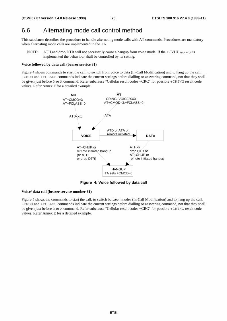
6.6 Alternating mode call control methodThis subclause describes the procedure to handle alternating mode calls with AT commands. Procedures are mandatorywhen alternating mode calls are implemented in the TA.
NOTE: ATH and drop DTR will not necessarily cause a hangup from voice mode. If the +CVHU $(AT R97)$ isimplemented the behaviour shall be controlled by its setting.
Voice followed by data call (bearer service 81)
Figure 4 shows commands to start the call, to switch from voice to data (In-Call Modification) and to hang up the call.+CMOD and +FCLASS commands indicate the current settings before dialling or answering command, not that they shallbe given just before D or A command. Refer subclause "Cellular result codes +CRC" for possible +CRING result codevalues. Refer Annex F for a detailed example.
VOICE DATA
HANGUP
AT+CHUP orremote initiated hangup(or ATHor drop DTR)
ATD or ATA orremote initiated
ATDxxx;
AT+CMOD=3AT+FCLASS=0
TA sets +CMOD=0
+CRING: VOICE/XXXAT+CMOD=3;+FCLASS=0
MTMO
ATH ordrop DTR orAT+CHUP orremote initiated hangup
ATA
Figure 4: Voice followed by data call
Voice/ data call (bearer service number 61)
Figure 5 shows the commands to start the call, to switch between modes (In-Call Modification) and to hang up the call.+CMOD and +FCLASS commands indicate the current settings before dialling or answering command, not that they shallbe given just before D or A command. Refer subclause "Cellular result codes +CRC" for possible +CRING result codevalues. Refer Annex E for a detailed example.

ETSI
ETSI TS 100 916 V7.4.0 (1999-11)24(GSM 07.07 version 7.4.0 Release 1998)
VOICE DATA
HANGUP
AT+CHUP orremote initiated hangup
AT+CHUP orremote initiated hangup(or ATHor drop DTR)
ATD or ATA orremote initiated
ATH or drop DTR orremote initiated
ATDxxxATDxxx;
AT+CMOD=2AT+FCLASS=0
TA sets +CMOD=0
+CRING: ALT VOICE/XXXAT+CMOD=2;+FCLASS=0
+CRING: ALT XXX/VOICEAT+CMOD=2;+FCLASS=0
MT voice first MT data firstMO
ATA ATA
Figure 5: Alternating voice and data call
Voice/ fax call (teleservice number 61)
Figure 6 shows the commands to start the call, to switch between modes (In-Call Modification) and to hang up the call.+CMOD and +FCLASS commands indicate the current settings before dialling or answering command, not that they shallbe given just before D or A command. The parameter "x" of +FCLASS command can be 1, 1.0, 2 or 2.0.
NOTE: The transition from fax mode to voice mode is for further study.
VOICE FAX
HANGUP
ATD orremote initiated
ATDxxxATDxxx;
AT+CMOD=1AT+FCLASS=x
TA sets +CMOD=0
+CRING: ALT VOICE/FAXAT+CMOD=1;+FCLASS=x
+CRING: ALT FAX/VOICEAT+CMOD=1;+FCLASS=x
MT voice first MT fax firstMO
ATA ATA
refer ITU-T T.31 [11] and T.32 [12]for different hangup possibilities(also AT+CHUP shall hangup)
AT+CHUP orremote initiated hangup(or ATHor drop DTR)
Figure 6: Alternating voice and fax call

ETSI
ETSI TS 100 916 V7.4.0 (1999-11)25(GSM 07.07 version 7.4.0 Release 1998)
6.7 Select bearer service type +CBST
Table 14: +CBST parameter command syntax
Command Possible response(s)+CBST=[<speed>[,<name>[,<ce>]]]+CBST? +CBST: <speed>,<name>,<ce>+CBST=? +CBST: (list of supported <speed>s),(list of
supported <name>s),(list of supported <ce>s)
Description
Set command selects the bearer service <name> with data rate <speed>, and the connection element <ce> to be usedwhen data calls are originated (refer GSM 02.02 [1]). Values may also be used during mobile terminated data call setup,especially in case of single numbering scheme calls (refer +CSNS).
Test command returns values supported by the TA as compound values.
Defined values
NOTE: The default values of the subparameters are manufacturer specific since they depend on the purpose of thedevice and data services provided by it. Not all combinations of these subparameters are supported byGSM (refer GSM 02.02 [1]).
<speed>:
0 autobauding (automatic selection of the speed; this setting is possible in case of 3.1 kHz modemand non-transparent service)
1 300 bps (V.21)2 1200 bps (V.22)3 1200/75 bps (V.23)4 2400 bps (V.22bis)5 2400 bps (V.26ter)6 4800 bps (V.32)7 9600 bps (V.32)12 9600 bps (V.34)14 14400 bps (V.34)15 19200 bps (V.34)16 28800 bps (V.34)34 1200 bps (V.120)36 2400 bps (V.120)38 4800 bps (V.120)39 9600 bps (V.120)43 14400 bps (V.120)47 19200 bps (V.120)48 28800 bps (V.120)49 38400 bps (V.120)50 48000 bps (V.120)51 56000 bps (V.120)65 300 bps (V.110)66 1200 bps (V.110)68 2400 bps (V.110 or X.31 flag stuffing)70 4800 bps (V.110 or X.31 flag stuffing)71 9600 bps (V.110 or X.31 flag stuffing)75 14400 bps (V.110 or X.31 flag stuffing)79 19200 bps (V.110 or X.31 flag stuffing)80 28800 bps (V.110 or X.31 flag stuffing)81 38400 bps (V.110 or X.31 flag stuffing)82 48000 bps (V.110 or X.31 flag stuffing)83 56000 bps (V.110 or X.31 flag stuffing)115 56000 bps (bit transparent)116 64000 bps (bit transparent)

ETSI
ETSI TS 100 916 V7.4.0 (1999-11)26(GSM 07.07 version 7.4.0 Release 1998)
also all other values below 128 are reserved by this TS
<name>:
0 data circuit asynchronous (UDI or 3.1 kHz modem)1 data circuit synchronous (UDI or 3.1 kHz modem)2 PAD Access (asynchronous) (UDI)3 Packet Access (synchronous) (UDI)4 data circuit asynchronous (RDI)5 data circuit synchronous (RDI)6 PAD Access (asynchronous) (RDI)7 Packet Access (synchronous) (RDI)
also all other values below 128 are reserved by this TS
<ce>:
0 transparent1 non-transparent2 both, transparent preferred3 both, non-transparent preferred
Implementation
Mandatory when data calls implemented.
6.8 Radio link protocol +CRLP
Table 15: +CRLP parameter command syntax
Command Possible response(s)+CRLP=[<iws>[,<mws>[,<T1>[,<N2>[,<ver>[,<T4>]]]]]]+CRLP? +CRLP: <iws>,<mws>,<T1>,<N2>[,<ver1>[,<T4>]]
[<CR><LF>+CRLP: <iws>,<mws>,<T1>,<N2>[,<ver2>[,<T4>]][...]]
+CRLP=? +CRLP: (list of supported <iws>s),(list of supported <mws>s),(list of supported <T1>s),(list of supported <N2>s)[,<ver1>[,(list of supported <T4>s)]][<CR><LF>+CRLP: (list of supported <iws>s),(list of supported<mws>s),(list of supported <T1>s),(list of supported <N2>s)[,<ver1>[,(list of supported <T4>s)]][...]]
Description
Radio link protocol (RLP) parameters used when non-transparent data calls are originated may be altered with setcommand. Available command subparameters depend on the RLP versions implemented by the device (e.g. <ver> maynot be available if device supports only versions 0 and 1).
NOTE: If radio link protocol is not used, but some other error correcting protocol (for transparent data calls),V.25ter [14] Error Control Selection test command +ES=? may be used to indicate the presence of theprotocol.
Read command returns current settings for each supported RLP version <verx>. Only RLP parameters applicable tothe corresponding <verx> are returned.
Test command returns values supported by the TA as a compound value. If ME/TA supports several RLP versions<verx>, the RLP parameter value ranges for each <verx> are returned in a separate line.
Defined values
<ver>, <verx>: RLP version number in integer format; when version indication is not present it shall equal 0

ETSI
ETSI TS 100 916 V7.4.0 (1999-11)27(GSM 07.07 version 7.4.0 Release 1998)
NOTE: Versions 0 and 1 share the same parameter set. Read and test commands shall return only one line for thisset (where <verx> is not present).
<iws>, <mws>, <T1>, <N2>, <T4>: IWF to MS window size, MS to IWF window size, acknowledgement timerT1, retransmission attempts N2, re-sequencing period T4 in integer format (default values and value rangesdepend on RLP version; refer GSM 04.22 [18]): T1 and T4 are in units of 10 ms.
Implementation
Mandatory when RLP implemented.
6.9 Service reporting control +CR
Table 16: +CR parameter command syntax
Command Possible response(s)+CR=[<mode>]+CR? +CR: <mode>+CR=? +CR: (list of supported <mode>s)
Description
Set command controls whether or not intermediate result code +CR: <serv> is returned from the TA to the TE. Ifenabled, the intermediate result code is transmitted at the point during connect negotiation at which the TA hasdetermined which speed and quality of service will be used, before any error control or data compression reports aretransmitted, and before the intermediate result code CONNECT is transmitted.
NOTE: This command replaces V.25ter [14] command Modulation Reporting Control +MR, which is notappropriate for use in the GSM network. Possible error control (other than radio link protocol) and datacompression reporting can be enabled with V.25ter commands Error Control Reporting +ER and DataCompression Reporting +DR.
Test command returns values supported by the TA as a compound value.
Defined values
<mode>:
0 disables reporting
1 enables reporting
<serv>:
ASYNC asynchronous transparent
SYNC synchronous transparent
REL ASYNC asynchronous non-transparent
REL SYNC synchronous non-transparent
GPRS [<L2P>] GPRS
The optional <L2P> proposes a layer 2 protocol to use between the MT and the TE. It is defined in the Enter GPRSData Mode (+CGDATA) command.
Implementation
Mandatory when data calls implemented.

ETSI
ETSI TS 100 916 V7.4.0 (1999-11)28(GSM 07.07 version 7.4.0 Release 1998)
6.10 Extended error report +CEER
Table 17: +CEER action command syntax
Command Possible response(s)+CEER +CEER: <report>+CEER=?
Description
Execution command causes the TA to return one or more lines of information text <report>, determined by the MEmanufacturer, which should offer the user of the TA an extended report of the reason for
- the failure in the last unsuccessful call setup (originating or answering) or in-call modification,
- the last call release,
- the last unsuccessful GPRS attach or unsuccessful PDP context activation,
- the last GPRS detach or PDP context deactivation.
Typically, the text will consist of a single line containing the cause information given by GSM network in textual format.
Defined values
<report>: the total number of characters, including line terminators, in the information text shall not exceed 2041characters.
Text shall not contain the sequence 0<CR> or OK<CR>
Implementation
Optional.
6.11 Cellular result codes +CRC
Table 18: +CRC parameter command syntax
Command Possible response(s)+CRC=[<mode>]+CRC? +CRC: <mode>+CRC=? +CRC: (list of supported <mode>s)
Description
Set command controls whether or not the extended format of incoming call indication or GPRS network request for PDPcontext activation is used. When enabled, an incoming call is indicated to the TE with unsolicited result code +CRING:<type> instead of the normal RING.
Test command returns values supported by the TA as a compound value.
NOTE: Similar command may be found in TIA IS-99 [15] and TIA IS-135 [16].
Defined values
<mode>:
0 disables extended format
1 enables extended format
<type>:
ASYNC asynchronous transparent

ETSI
ETSI TS 100 916 V7.4.0 (1999-11)29(GSM 07.07 version 7.4.0 Release 1998)
SYNC synchronous transparent
REL ASYNC asynchronous non-transparent
REL SYNC synchronous non-transparent
FAX facsimile (TS 62)
VOICE normal voice (TS 11)
VOICE/XXX voice followed by data (BS 81) (XXX is ASYNC, SYNC, REL ASYNC or REL SYNC)
ALT VOICE/XXX alternating voice/data, voice first (BS 61)
ALT XXX/VOICE alternating voice/data, data first (BS 61)
ALT VOICE/FAX alternating voice/fax, voice first (TS 61)
ALT FAX/VOICE alternating voice/fax, fax first (TS 61)
GPRS <PDP_type>, <PDP_addr>[, <L2P>] GPRS network request for PDP context activation
<PDP_type> and <PDP_addr> are as defined in the Define PDP Context (+CGDCONT) command. The optional<L2P> proposes a layer 2 protocol to use between the MT and the TE. It is defined in the Enter GPRS Data Mode(+CGDATA) command. If the MT is unable to announce to the TE the network's request (for example it is in V.25teronline data state) the MT shall reject the request. No corresponding unsolicited result code shall be issued when the MTreturns to a command state.
Implementation
Mandatory when data or fax circuit mode calls implemented.
6.12 HSCSD device parameters +CHSD
Table 19: +CHSD action command syntax
Command Possible response(s)+CHSD +CHSD: <mclass>,<maxRx>,<maxTx>,<sum>,<codings>
+CME ERROR: <err>+CHSD=?
Description
Execution command returns information about HSCSD features (refer GSM 02.34 [29]) supported by the ME/TA. Refersubclause 9.2 for possible <err> values.
Defined values
<mclass>: integer type; multislot class
<maxRx>: integer type; maximum number of receive timeslots that ME can use
<maxTx>: integer type; maximum number of transmit timeslots that ME can use
<sum>: integer type; total number of receive and transmit timeslots that ME can use at the same time (per TDMAframe). The following applies in a HSCSD call: 1 ≤ (receive slots) + (transmit slots) ≤ <sum>
<codings> is a sum of integers each representing a supported channel coding (e.g. value 5 indicates that 4.8k and9.6k channel codings are supported):
1 4.8k full rate data traffic channel
4 9.6k full rate data traffic channel
8 14.4k full rate data traffic channel

ETSI
ETSI TS 100 916 V7.4.0 (1999-11)30(GSM 07.07 version 7.4.0 Release 1998)
Implementation
Mandatory when HSCSD implemented.
6.13 HSCSD transparent call configuration +CHST
Table 20: +CHST parameter command syntax
Command Possible response(s)+CHST=[<wRx>[,<codings>]]+CHST? +CHST: <wRx>,<codings>+CHST=?
Description
Set command controls parameters for transparent HSCSD calls. Changing them during a call does not affect the currentcall.
Defined values
<wRx>: integer type; wanted amount of receive timeslots. Default value 0 indicates that TA shall calculate a propervalue from currently selected fixed network user rate (<speed> subparameter from +CBST command) and<codings>
<codings>: a sum of integers each representing a channel coding that is accepted for transparent HSCSD calls.Default value 0 indicates that all supported codings are accepted (refer +CHSD command for other values)
Implementation
Mandatory when transparent HSCSD implemented.
6.14 HSCSD non-transparent call configuration +CHSN
Table 21: +CHSN parameter command syntax
Command Possible response(s)+CHSN=[<wAiur>[,<wRx>[,<topRx>[,<codings>]]]]+CHSN? +CHSN: <wAiur>,<wRx>,<topRx>,<codings>+CHSN=? +CHSN: (list of supported <wAiur>s), (list of supported
<wRx>s),(list of supported <topRx>,(list of supported<codings>s)
Description
Set command controls parameters for non-transparent HSCSD calls. Changing <topRx> or <codings> value duringa call does not affect the current call. Changing of <wAiur> or <wRx> affects the current call only if <topRx> wasnon-zero when call was established.
Defined values
<wAiur>: integer type; wanted air interface user rate. Default value 0 indicates that TA shall calculate a propervalue from currently selected fixed network user rate (<speed> subparameter from +CBST command),<codings>, and <wRx> (or <maxRx> from +CHSD command if <wRx>=0). Other values:
1 9600 bps
2 14400 bps
3 19200 bps
4 28800 bps

ETSI
ETSI TS 100 916 V7.4.0 (1999-11)31(GSM 07.07 version 7.4.0 Release 1998)
5 38400 bps
6 43200 bps
7 57600 bps
<wRx>: integer type; wanted amount of receive timeslots. Default value 0 indicates that TA shall calculate a propervalue from currently selected <wAiur> and <codings>
<topRx>: integer type; top value for <wRx> that user is going to request during the next established non-transparent HSCSD call. Default value 0 indicates that user is not going to change <wAiur>/<wRx> during thenext call
<codings>: a sum of integers each representing a channel coding that is accepted for non-transparent HSCSDcalls. Default value 0 indicates that all supported codings are accepted (refer +CHSD command for other values)
Implementation
Mandatory when non-transparent HSCSD implemented.
6.15 HSCSD current call parameters +CHSC
Table 22: +CHSC action command syntax
Command Possible response(s)+CHSC +CHSC: <rx>,<tx>,<aiur>,<coding>+CHSC=?
Description
Execution command returns information about current HSCSD call. If no HSCSD call is active, all parameters returnedshall equal zero. (It is manufacturer specific whether non-zero information is returned in case of an active normal single-slot data call.)
Defined values
<rx>: integer type; number of receive timeslots currently in use
<tx>: integer type; number of transmit timeslots currently in use
<aiur>: integer type; current air interface user rate (in case of transparent service this equals fixed network userrate) (refer +CHSN command for possible values)
<coding>: current channel coding (refer +CHSD command for possible values)
Implementation
Optional.
6.16 HSCSD parameters report +CHSR$(AT R98)$
Table 23: +CHSR action command syntax
Command Possible response(s)+CHSR=[<mode>]+CHSR? +CHSR: <mode>+CHSR=? +CHSR: (list of supported <mode>s)
Description

ETSI
ETSI TS 100 916 V7.4.0 (1999-11)32(GSM 07.07 version 7.4.0 Release 1998)
Enabled command returns intermediate result code +CHSR: <type> from the TA to the TE when an HSCSD call isbeing set up. The result code represents the current (negotiated or renegotiated) HSCSD parameters. If enabled, theintermediate result code is transmitted at the point of the call setup negotiation where the TA has determined what typeof an HSCSD connection will be used. Result code transmission is done after possible service (+CR), error control(+ER), and/or compression (+DR) reporting but before possible TE-TA rate (+ILRR) reporting and before theintermediate result code CONNECT is transmitted. The format of the intermediate result code is:
+CHSR: <rx>,<tx>,<aiur>,<coding>
For the value definitions, refer to +CHSN and +CHSC commands. For instance, for a non-transparent HSCSD call, resultcode ‘+CHSR: 2,2,4,8’ means that the call has two timeslots in both up- and downlink, the air interface user rate is28800 bps, and the used channel coding TCH/F14.4.
Defined values
<mode>:
0 disables reporting
1 enables reporting
Implementation
Mandatory when HSCSD implemented
6.17 HSCSD automatic user initiated upgrading +CHSU$(AT R98)$
Table 24: +CHSU parameter command syntax
Command Possible response(s)+CHSU=<mode>+CHSU? +CHSU: <mode>+CHSU=? +CHSU: (list of supported <mode>s)
Description
Set command controls whether or not automatic user initiated service level upgrading shall be used for non-transparentHSCSD calls. “Automatic” means that, if enabled, the ME/TA shall use the UP bit in the received RLP frames todetermine when to initiate user initiated service level upgrading (i.e. when to modify the +CHSN parameters <wAiur>and/or <wRx> for the current call). Refer to GSM 07.01 for details on the interpretation of the UP bit(s).
NOTE: The validity of the UP bit in the RLP frames depends on the result of the RLP negotiations. The UP bitshall only be used if the result of the RLP negotiations were successful with respect to the UP bit.
Defined values
<mode>:
0 disables use of UP bit for upgrading
1 enables use of UP bit for upgrading
Implementation
Optional

ETSI
ETSI TS 100 916 V7.4.0 (1999-11)33(GSM 07.07 version 7.4.0 Release 1998)
6.18 Single numbering scheme +CSNS
Table 25: +CSNS parameter command syntax
Command Possible response(s)+CSNS=[<mode>]+CSNS? +CSNS: <mode>+CSNS=? +CSNS: (list of supported <mode>s)
Description
Set command selects the bearer or teleservice to be used when mobile terminated single numbering scheme call isestablished. Parameter values set with +CBST command shall be used when <mode> equals to a data service. If +CBSTparameter is set to a value that is not applicable to single numbering calls, ME/TA shall map the value to the closestvalid one. E.g. if user has set <speed>=71, <name>=2 and <ce>=1 (non-transparent asynchronous 9600 bps V.110ISDN connection) for mobile originated calls, ME/TA shall map the values into non-transparent asynchronous 9600 bpsV.32 modem connection when single numbering scheme call is answered.
Test command returns values supported by the TA as compound values.
Defined values
<mode>:
0 voice
1 alternating voice/fax, voice first (TS 61)
2 fax (TS 62)
3 alternating voice/data, voice first (BS 61)
4 data
5 alternating voice/fax, fax first (TS 61)
6 alternating voice/data, data first (BS 61)
7 voice followed by data (BS 81)
Implementation
Optional.
6.19 Voice Hangup Control +CVHU $(AT R97)$
Table 26: +CVHU parameter command syntax
Command Possible response(s)+CVHU=[<mode>]+CVHU? +CVHU:<mode>+CVHU=? +CVHU:(list of supported <mode>s)
Description
Set command selects whether ATH or “drop DTR” shall cause a voice connection to be disconnected or not. By voiceconnection is also meant alternating mode calls that are currently in voice mode. (See section 6.6).
NOTE: When <mode> = 2, this command must be seen in conjunction with the V.25ter [14] command &D. Else&D shall be ignored.
Defined values
<mode>:

ETSI
ETSI TS 100 916 V7.4.0 (1999-11)34(GSM 07.07 version 7.4.0 Release 1998)
0 “Drop DTR” ignored but OK response given. ATH disconnects.
1 “Drop DTR” and ATH ignored but OK response given.
2 “Drop DTR” behaviour according to &D setting. ATH disconnects.
Implementation
Optional
6.20 V.120 rate adaption protocol +CV120
Table 27: +CV120 parameter command syntax
Command Possible response(s)+CV120=[<rah>[,<mfm>[,<mode>[,<llineg>[,<assign>[,<negtype>]]]]]]+CV120? +CV120: <rah>,<mfm>,<mode>,<llineg>,
<assign>,<negtype>+CV120=? +CV120: (list of supported <rah>s),(list of supported
<mfm>s),(list of supported <mode>s),(list of supported<llineg>s),(list of supported <assign>s),(list ofsupported <negtype>s)
Description
Set command sets the values of the V.120 protocol parameters (defined in CCITT V.120) that are carried in the GSMBC and/or LLC information elements.
Read command returns current settings for the V.120 parameters.
Test command returns values supported by the TA as a compound value.
Defined values
<rah>
0 rate adaption header not included
1 rate adaption header included (mandatory for protocol sensitive modes).
<mfm>
0 multiple frame establishment not supported, only UI frames allowed
1 multiple frame establishment supported, both I and UI frames allowed.
<mode>
0 bit transparent mode of operation
1 protocol sensitive mode of operation.
<llineg>
0 no negotiation, LLI = 256 only
1 negotiation allowed. Note - <negtype> indicates the connection over which the negotiation is performed.
<assign>
0 message originator is "default assignee"
1 message originator is "assignor only".

ETSI
ETSI TS 100 916 V7.4.0 (1999-11)35(GSM 07.07 version 7.4.0 Release 1998)
<negtype>
0 negotiation is done using logical link zero
1 negotiation is done with USER INFORMATION messages on a temporary signalling connection.
GSM does not support all the possible modes of V.120 operation. However, in order to accommodate possible futureadditions, the complete set of parameters is included in the command.
The permitted values are: 1, 1 or 0, 1, 0, 0, 0.
A recommended set of default values is: 1, 1, 1, 0, 0, 0.
Implementation
Mandatory, if the ME supports V.120 interworking.

ETSI
ETSI TS 100 916 V7.4.0 (1999-11)36(GSM 07.07 version 7.4.0 Release 1998)
6.21 ITU-T V.25ter [14] call control commands
Table 28: V.25ter call control commands
Command Section Impl. Use in GSMD[<dial_string>][;]
6.3.1 mand. originates a call
T 6.3.2 mand. ignored (select tone dialling)P 6.3.3 mand. ignored (select pulse dialling)A 6.3.5 mand. answer a callH[<value>] 6.3.6 mand. hang-up a single mode call; for alternate mode call refer subclause
"Hangup call +CHUP" (only value equal to zero needed)O[<value>] 6.3.7 mand. returns TA to online data state from online command mode (only value
equal to zero needed)S0=[<value>] 6.3.8 mand. sets the number of call indications (rings) before automatically
answering the call; value equalling zero disables automatic answeringand is the default
S6=[<value>] 6.3.9 mand. ignored (pause before blind dialling)S7=[<value>] 6.3.10 mand. sets number of seconds to wait for completion of call answering or
originating procedure before giving up and disconnectingS8=[<value>] 6.3.11 mand. sets number of seconds to wait when comma dial modifier encountered
in dial string of D command (default is 2 seconds)S10=[<value>] 6.3.12 mand. sets number of tenths of seconds to wait before disconnecting after TA
has indicated the absence of received line signalL[<value>] 6.3.13 mand. ignored (monitor speaker loudness)M[<value>] 6.3.14 mand. ignored (monitor speaker mode)
6.22 ITU-T V.25ter [14] data compression commands
Table 29: V.25ter data compression commands
Command Section Impl. Use in GSM+DS=[<dir>[,<neg>[,<P1>[,<P2>]]]]
6.6.1 mand.whenV.42bis
controls ITU-T Recommendation V.42bis data compressionfunctions; for subparameter defaults in GSM referGSM 04.22 [18]
+DR=[<value>] 6.6.2 mand.whenV.42bis
determines whether the use of V.42bis is informed usingintermediate result code +DR: <type> before going onlinedata state after call answering or originating
6.23 Informative examplesThe alternating mode call handling (voice and fax, or voice and data) and the data call setup commands are defined suchthat the dialling command of V.25ter [14] (D) still always originates a call. The purpose is to support all current TEapplications using the dialling command as default. Fax calls are controlled following the rules of ITU-T T.31 [11] andT.32 [12] standards.
An example where a voice call is originated:
ATD+1 812 555673I; (type of address defaults to 145, CLI presentation is restricted for this call)OK (call setup was successful)
An example where a voice call is attempted from a phonebook:
ATD>"Doe Joe"G; (enable CUG control for this call)+CME ERROR: 22 (entry "Doe Joe" is not found)
Also supplementary services may be controlled using dial command according to GSM 02.30 [19]. An example of callforwarding on no reply for telephony with the adjustment of the no reply condition timer on 25 seconds:
ATD**61*+1812555673*11*25#

ETSI
ETSI TS 100 916 V7.4.0 (1999-11)37(GSM 07.07 version 7.4.0 Release 1998)
OK (modification was successful)
Two new commands are created for controlling the alternating mode calls. First one, Call Mode (+CMOD), selectsbetween single and alternating mode. Because this is a crucial command, it is defined that the value is set back tozero (single mode) after every successfully originated alternating mode call. Also on power-up and factory or userresets, the value is set to zero. The second new command, Hangup Call (+CHUP), is not a replacement of V.25ter [14]command H, but a command which reliably disconnects the call in GSM network. This is defined because the Hcommand is used to switch from fax or data mode to voice mode.
The setting of GSM bearer service (data circuit duplex asynchronous and synchronous, PAD access circuitasynchronous, or data packet duplex synchronous), is done with Select Bearer Service Type (+CBST). It chooses one ofthe four mentioned bearer services, the data rate of the service (or actually the modulation when modem IWFs are used),and enables or disables RLP. Command Radio Link Protocol (+CRLP) is used to set the RLP parameters in the radiopath.
Service Reporting Control command (+CR) is defined similarly as the reporting of modulation, V.18, error control, anddata compression which are V.25ter [14] features used to show information about the type of the established connectionbefore the CONNECT intermediate result code. +CR command has one subparameter which specifies whether theintermediate result code +CR: <serv> is returned or not. The result code should be returned before any V.25ter [14]reporting result codes. An example of setting up an asynchronous 9600 bit/s modem connection with service reporting:
AT+CBST=7,0,1 (asynchronous modem 9600 bit/s and RLP)OKAT+CR=1 (enable reporting)OKATD1234567890+CR: REL ASYNCCONNECT 9600
As GSM network offers more information about the reason of the failure in call originating and answering than normalPSTN, it is useful to add an extra command to return this information to the TE. This information should not be returnedalways after unsuccessful call originating or answering, because many TE applications look for just the regular NOCARRIER, BUSY, NO ANSWER and CONNECT messages. Action command Extended Error Report (+CEER) does nothave any subparameters, and it returns the cause of the latest call setup failure. This information may be the textualpresentation of the GSM network failure code (refer GSM specification 04.08 [8] Annex H), or some other informationdefined by the TA manufacturer.
7 Network service related commandsThis clause describes GSM network related commands, which are not covered in call control clause of this TS.Commands include GSM supplementary service handling, MSISDN query, ME and network facility locking, andnetwork registration information query.
7.1 Subscriber number +CNUM
Table 30: +CNUM action command syntax
Command Possible response(s)+CNUM +CNUM: [<alpha1>],<number1>,<type1>[,<speed>,<service>[,<itc>]]
[<CR><LF>+CNUM: [<alpha2>],<number2>,<type2>[,<speed>,<service>[,<itc>]]
[...]]+CME ERROR: <err>
+CNUM=?
Description
Action command returns the MSISDNs related to the subscriber (this information can be stored in the SIM or in theME). If subscriber has different MSISDN for different services, each MSISDN is returned in a separate line. Refersubclause 9.2 for possible <err> values.
Defined values

ETSI
ETSI TS 100 916 V7.4.0 (1999-11)38(GSM 07.07 version 7.4.0 Release 1998)
<alphax>: optional alphanumeric string associated with <numberx>; used character set should be the oneselected with command Select TE Character Set +CSCS
<numberx>: string type phone number of format specified by <typex>
<typex>: type of address octet in integer format (refer GSM 04.08 [8] subclause 10.5.4.7)
<speed>: as defined in subclause 6.7
<service> (service related to the phone number):
0 asynchronous modem
1 synchronous modem
2 PAD Access (asynchronous)
3 Packet Access (synchronous)
4 voice
5 fax
also all other values below 128 are reserved by this TS
<itc> (information transfer capability):
0 3.1 kHz
1 UDI
Implementation
Optional.
7.2 Network registration +CREG
Table 31: +CREG parameter command syntax
Command Possible response(s)+CREG=[<n>]+CREG? +CREG: <n>,<stat>[,<lac>,<ci>]
+CME ERROR: <err>+CREG=? +CREG: (list of supported <n>s)
Description
Set command controls the presentation of an unsolicited result code +CREG: <stat> when <n>=1 and there is achange in the ME network registration status, or code +CREG: <stat>[,<lac>,<ci>] when <n>=2 and there isa change of the network cell.
Read command returns the status of result code presentation and an integer <stat> which shows whether the networkhas currently indicated the registration of the ME. Location information elements <lac> and <ci> are returned onlywhen <n>=2 and ME is registered in the network. Refer subclause 9.2 for possible <err> values.

ETSI
ETSI TS 100 916 V7.4.0 (1999-11)39(GSM 07.07 version 7.4.0 Release 1998)
Defined values
<n>:
0 disable network registration unsolicited result code
1 enable network registration unsolicited result code +CREG: <stat>
2 enable network registration and location information unsolicited result code +CREG:<stat>[,<lac>,<ci>]
<stat>:
0 not registered, ME is not currently searching a new operator to register to
1 registered, home network
2 not registered, but ME is currently searching a new operator to register to
3 registration denied
4 unknown
5 registered, roaming
<lac>: string type; two byte location area code in hexadecimal format (e.g. "00C3" equals 195 in decimal)
<ci>: string type; two byte cell ID in hexadecimal format
Implementation
Optional.
7.3 Operator selection +COPS
Table 32: +COPS parameter command syntax
Command Possible response(s)+COPS=[<mode>[,<format>[,<oper>]]]
+CME ERROR: <err>
+COPS? +COPS: <mode>[,<format>,<oper>]+CME ERROR: <err>
+COPS=? +COPS: [list of supported (<stat>,long alphanumeric <oper>,short alphanumeric <oper>,numeric <oper>)s][,,(list of supported <mode>s),(list of supported <format>s)]+CME ERROR: <err>
Description
Set command forces an attempt to select and register the GSM network operator. <mode> is used to select whether theselection is done automatically by the ME or is forced by this command to operator <oper> (it shall be given informat <format>). If the selected operator is not available, no other operator shall be selected (except <mode>=4).The selected operator name format shall apply to further read commands (+COPS?) also. <mode>=2 forces an attemptto deregister from the network. The selected mode affects to all further network registration (e.g. after <mode>=2, MEshall be unregistered until <mode>=0 or 1 is selected). Refer subclause 9.2 for possible <err> values. This commandshould be abortable when registration/deregistration attempt is made.
Read command returns the current mode and the currently selected operator. If no operator is selected, <format> and<oper> are omitted.
Test command returns a list of quadruplets, each representing an operator present in the network. Quadruplet consists ofan integer indicating the availability of the operator <stat>, long and short alphanumeric format of the name of theoperator, and numeric format representation of the operator. Any of the formats may be unavailable and should then bean empty field. The list of operators shall be in order: home network, networks referenced in SIM, and other networks.

ETSI
ETSI TS 100 916 V7.4.0 (1999-11)40(GSM 07.07 version 7.4.0 Release 1998)
It is recommended (although optional) that after the operator list TA returns lists of supported <mode>s and<format>s. These lists shall be delimited from the operator list by two commas.
Defined values
<mode>:
0 automatic (<oper> field is ignored)
1 manual (<oper> field shall be present)
2 deregister from network
3 set only <format> (for read command +COPS?), do not attempt registration/deregistration (<oper> field isignored); this value is not applicable in read command response
4 manual/automatic (<oper> field shall be present); if manual selection fails, automatic mode (<mode>=0) isentered
<format>:
0 long format alphanumeric <oper>
1 short format alphanumeric <oper>
2 numeric <oper>
<oper>: string type; <format> indicates if the format is alphanumeric or numeric; long alphanumeric format canbe upto 16 characters long and short format up to 8 characters (refer GSM MoU SE.13 [9]); numeric format isthe GSM Location Area Identification number (refer GSM 04.08 [8] subclause 10.5.1.3) which consists of athree BCD digit country code coded as in ITU-T E.212 Annex A [10], plus a two BCD digit network code, whichis administration specific; returned <oper> shall not be in BCD format, but in IRA characters converted fromBCD; hence the number has structure: (country code digit 3)(country code digit 2)(country code digit 1)(networkcode digit 2)(network code digit 1)
<stat>:
0 unknown
1 available
2 current
3 forbidden
Implementation
Optional.
7.4 Facility lock +CLCK
Table 33: +CLCK action command syntax
Command Possible response(s)+CLCK=<fac>,<mode>[,<passwd>[,<class>]]
+CME ERROR: <err>when <mode>=2 and command successful:+CLCK: <status>[,<class1>[<CR><LF>+CLCK: <status>,<class2>[...]]
+CLCK=? +CLCK: (list of supported <fac>s)+CME ERROR: <err>
Description

ETSI
ETSI TS 100 916 V7.4.0 (1999-11)41(GSM 07.07 version 7.4.0 Release 1998)
Execute command is used to lock, unlock or interrogate a ME or a network facility <fac>. Password is normallyneeded to do such actions. When querying the status of a network service (<mode>=2) the response line for ‘not active’case (<status>=0) should be returned only if service is not active for any <class>. Refer subclause 9.2 for possible<err> values. This command should be abortable when network facilities are set or interrogated.
Call barring facilities are based on GSM supplementary services (refer GSM 02.88 [6]). The interaction of these withother commands based on other GSM supplementary services is described in the GSM standard.
Test command returns facility values supported by the TA as a compound value.
Defined values
<fac> values reserved by this TS:
"CS" CNTRL (lock CoNTRoL surface (e.g. phone keyboard))
"PS" PH-SIM (lock PHone to SIM card) (ME asks password when other than current SIM card inserted; ME mayremember certain amount of previously used cards thus not requiring password when they are inserted)
"PF" lock Phone to the very First inserted SIM card (also referred in this TS as PH-FSIM) (ME asks passwordwhen other than the first SIM card is inserted)
"SC" SIM (lock SIM card) (SIM asks password in ME power-up and when this lock command issued)
"AO" BAOC (Barr All Outgoing Calls) (refer GSM 02.88 [6] clause 1)
"OI" BOIC (Barr Outgoing International Calls) (refer GSM 02.88 [6] clause 1)
"OX" BOIC-exHC (Barr Outgoing International Calls except to Home Country) (refer GSM 02.88 [6] clause 1)
"AI" BAIC (Barr All Incoming Calls) (refer GSM 02.88 [6] clause 2)
"IR" BIC-Roam (Barr Incoming Calls when Roaming outside the home country) (refer GSM 02.88 [6] clause 2)
"NT" barr incoming calls from numbers Not stored to TA memory
"NM" barr incoming calls from numbers Not stored to ME memory
"NS" barr incoming calls from numbers Not stored to SIM memory
"NA" barr incoming calls from numbers Not stored in Any memory
"AB" All Barring services (refer GSM 02.30 [19]) (applicable only for <mode>=0)
"AG" All outGoing barring services (refer GSM 02.30 [19]) (applicable only for <mode>=0)
"AC" All inComing barring services (refer GSM 02.30 [19]) (applicable only for <mode>=0)
"FD" SIM fixed dialling memory feature (if PIN2 authentication has not been done during the current session, PIN2is required as <passwd>)
"PN" Network Personalisation (refer GSM 02.22 [33])
"PU" network sUbset Personalisation (refer GSM 02.22 [33])
"PP" service Provider Personalisation (refer GSM 02.22 [33])
"PC" Corporate Personalisation (refer GSM 02.22 [33])
<mode>:
0 unlock
1 lock
2 query status
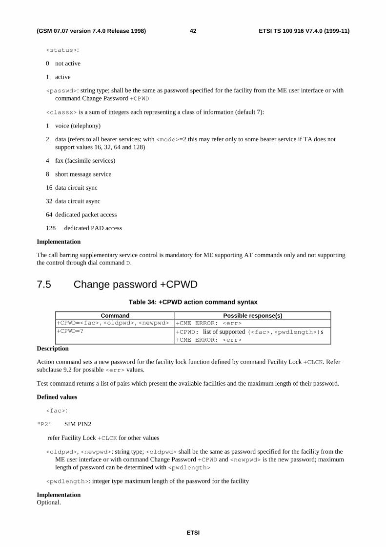
ETSI
ETSI TS 100 916 V7.4.0 (1999-11)42(GSM 07.07 version 7.4.0 Release 1998)
<status>:
0 not active
1 active
<passwd>: string type; shall be the same as password specified for the facility from the ME user interface or withcommand Change Password +CPWD
<classx> is a sum of integers each representing a class of information (default 7):
1 voice (telephony)
2 data (refers to all bearer services; with <mode>=2 this may refer only to some bearer service if TA does notsupport values 16, 32, 64 and 128)
4 fax (facsimile services)
8 short message service
16 data circuit sync
32 data circuit async
64 dedicated packet access
128 dedicated PAD access
Implementation
The call barring supplementary service control is mandatory for ME supporting AT commands only and not supportingthe control through dial command D.
7.5 Change password +CPWD
Table 34: +CPWD action command syntax
Command Possible response(s)+CPWD=<fac>,<oldpwd>,<newpwd> +CME ERROR: <err>+CPWD=? +CPWD: list of supported (<fac>,<pwdlength>)s
+CME ERROR: <err>
Description
Action command sets a new password for the facility lock function defined by command Facility Lock +CLCK. Refersubclause 9.2 for possible <err> values.
Test command returns a list of pairs which present the available facilities and the maximum length of their password.
Defined values
<fac>:
"P2" SIM PIN2
refer Facility Lock +CLCK for other values
<oldpwd>, <newpwd>: string type; <oldpwd> shall be the same as password specified for the facility from theME user interface or with command Change Password +CPWD and <newpwd> is the new password; maximumlength of password can be determined with <pwdlength>
<pwdlength>: integer type maximum length of the password for the facility
ImplementationOptional.

ETSI
ETSI TS 100 916 V7.4.0 (1999-11)43(GSM 07.07 version 7.4.0 Release 1998)
7.6 Calling line identification presentation +CLIP
Table 35: +CLIP parameter command syntax
Command Possible response(s)+CLIP=[<n>]+CLIP? +CLIP: <n>,<m>+CLIP=? +CLIP: (list of supported <n>s)
Description
This command refers to the GSM supplementary service CLIP (Calling Line Identification Presentation) that enables acalled subscriber to get the calling line identity (CLI) of the calling party when receiving a mobile terminated call. Setcommand enables or disables the presentation of the CLI at the TE. It has no effect on the execution of thesupplementary service CLIP in the network.
When the presentation of the CLI at the TE is enabled (and calling subscriber allows), +CLIP:<number>,<type>[,<subaddr>,<satype>[,[<alpha>][,<CLI validity>]]] response is returnedafter every RING (or +CRING: <type>; refer subclause "Cellular result codes +CRC") result code sent from TA toTE. It is manufacturer specific if this response is used when normal voice call is answered.
Read command gives the status of <n>, and also triggers an interrogation of the provision status of the CLIP serviceaccording GSM 02.81 [3] (given in <m>).Test command returns values supported by the TA as a compound value.
Defined values
<n> (parameter sets/shows the result code presentation status in the TA):
0 disable
1 enable
<m> (parameter shows the subscriber CLIP service status in the network):
0 CLIP not provisioned
1 CLIP provisioned
2 unknown (e.g. no network, etc.)
<number>: string type phone number of format specified by <type>
<type>: type of address octet in integer format (refer GSM 04.08 [8] subclause 10.5.4.7)
<subaddr>: string type subaddress of format specified by <satype>
<satype>: type of subaddress octet in integer format (refer GSM 04.08 [8] subclause 10.5.4.8)
<alpha>: optional string type alphanumeric representation of <number> corresponding to the entry found inphonebook; used character set should be the one selected with command Select TE Character Set +CSCS
<CLI validity>:
0 CLI valid
1 CLI has been withheld by the originator.
2 CLI is not available due to interworking problems or limitations of originating network.
Implementation
Optional.

ETSI
ETSI TS 100 916 V7.4.0 (1999-11)44(GSM 07.07 version 7.4.0 Release 1998)
7.7 Calling line identification restriction +CLIR
Table 36: +CLIR parameter command syntax
Command Possible response(s)+CLIR=[<n>]+CLIR? +CLIR: <n>,<m>+CLIR=? +CLIR: (list of supported <n>s)
Description
This command refers to CLIR-service according to GSM 02.81 [3] that allows a calling subscriber to enable or disablethe presentation of the CLI to the called party when originating a call.
Set command overrides the CLIR subscription (default is restricted or allowed) when temporary mode is provisioned asa default adjustment for all following outgoing calls. This adjustment can be revoked by using the opposite command.. Ifthis command is used by a subscriber without provision of CLIR in permanent mode the network will act accordingGSM 02.81 [3].
Read command gives the default adjustment for all outgoing calls (given in <n>), and also triggers an interrogation ofthe provision status of the CLIR service (given in <m>). Test command returns values supported by the TA as acompound value.
NOTE: On a per call base CLIR functionality is explained in subclause "ITU-T V.25ter [14] dial command".
Defined values
<n> (parameter sets the adjustment for outgoing calls):
0 presentation indicator is used according to the subscription of the CLIR service
1 CLIR invocation
2 CLIR suppression
<m> (parameter shows the subscriber CLIR service status in the network):
0 CLIR not provisioned
1 CLIR provisioned in permanent mode
2 unknown (e.g. no network, etc.)
3 CLIR temporary mode presentation restricted
4 CLIR temporary mode presentation allowed
Implementation
Optional.
7.8 Connected line identification presentation +COLP
Table 37: +COLP parameter command syntax
Command Possible response(s)+COLP=[<n>]+COLP? +COLP: <n>,<m>+COLP=? +COLP: (list of supported <n>s)
Description

ETSI
ETSI TS 100 916 V7.4.0 (1999-11)45(GSM 07.07 version 7.4.0 Release 1998)
This command refers to the GSM supplementary service COLP (Connected Line Identification Presentation) thatenables a calling subscriber to get the connected line identity (COL) of the called party after setting up a mobileoriginated call. The command enables or disables the presentation of the COL at the TE. It has no effect on theexecution of the supplementary service COLR in the network.
When enabled (and called subscriber allows), +COLP:<number>,<type>[,<subaddr>,<satype> [,<alpha>]] intermediate result code is returned from TA toTE before any +CR or V.25ter [14] responses. It is manufacturer specific if this response is used when normal voice callis established.
Read command gives the status of <n>, and also triggers an interrogation of the provision status of the COLP serviceaccording GSM 02.81 [3] (given in <m>).
Test command returns values supported by the TA as a compound value.
Defined values
<n> (parameter sets/shows the result code presentation status in the TA):
0 disable
1 enable
<m> (parameter shows the subscriber COLP service status in the network):
0 COLP not provisioned
1 COLP provisioned
2 unknown (e.g. no network, etc.)
<number>, <type>, <subaddr>, <satype>, <alpha>: refer +CLIP
Implementation
Optional.
7.9 Closed user group +CCUG
Table 38: +CCUG parameter command syntax
Command Possible response(s)+CCUG=[<n>[,<index>[,<info>]]]+CCUG? +CCUG: <n>,<index>,<info>+CCUG=?
Description
This command allows control of the Closed User Group supplementary service (refer GSM 02.85 [21]). Set commandenables the served subscriber to select a CUG index, to suppress the Outgoing Access (OA), and to suppress thepreferential CUG.
Set command with <n>=1 enables to control the CUG information on the air interface as a default adjustment for allfollowing outgoing calls. The interaction of this command with other commands based on other GSM supplementaryservices is described in the GSM standard.
NOTE: On a per call base CUG functionality is explained in subclause "ITU-T V.25ter [14] dial command".
Defined values
<n>:
0 disable CUG temporary mode
1 enable CUG temporary mode

ETSI
ETSI TS 100 916 V7.4.0 (1999-11)46(GSM 07.07 version 7.4.0 Release 1998)
<index>:
0...9 CUG index
10 no index (preferred CUG taken from subscriber data)
<info>:
0 no information
1 suppress OA
2 suppress preferential CUG
3 suppress OA and preferential CUG
Implementation
Optional.
7.10 Call forwarding number and conditions +CCFC
Table 39: +CCFC action command syntax
Command Possible response(s)+CCFC=<reason>,<mode>[,<number>[,<type>[,<class>[,<subaddr>[,<satype>[,<time>]]]]]]
+CME ERROR: <err>when <mode>=2 and command successful:+CCFC: <status>,<class1>[,<number>,<type>[,<subaddr>,<satype>[,<time>]]][<CR><LF>+CCFC: <status>,<class2>[,<number>,<type>[,<subaddr>,<satype>[,<time>]]][...]]
+CCFC=? +CCFC: (list of supported <reason>s)
Description
This command allows control of the call forwarding supplementary service according to GSM 02.82 [4]. Registration,erasure, activation, deactivation, and status query are supported. When querying the status of a network service(<mode>=2) the response line for ‘not active’ case (<status>=0) should be returned only if service is not active forany <class>.
Test command returns reason values supported by the TA as a compound value.
Defined values
<reason>:
0 unconditional
1 mobile busy
2 no reply
3 not reachable
4 all call forwarding (refer GSM 02.30 [19])
5 all conditional call forwarding (refer GSM 02.30 [19])
<mode>:
0 disable
1 enable

ETSI
ETSI TS 100 916 V7.4.0 (1999-11)47(GSM 07.07 version 7.4.0 Release 1998)
2 query status
3 registration
4 erasure
<number>: string type phone number of forwarding address in format specified by <type>
<type>: type of address octet in integer format (refer GSM 04.08 [8] subclause 10.5.4.7); default 145 whendialling string includes international access code character "+", otherwise 129
<subaddr>: string type subaddress of format specified by <satype>
<satype>: type of subaddress octet in integer format (refer GSM 04.08 [8] subclause 10.5.4.8); default 128
<classx> is a sum of integers each representing a class of information (default 7):
1 voice (telephony)
2 data (refers to all bearer services; with <mode>=2 this may refer only to some bearer service if TA does notsupport values 16, 32, 64 and 128)
4 fax (facsimile services)
8 short message service
16 data circuit sync
32 data circuit async
64 dedicated packet access
128 dedicated PAD access
<time>:
1...30 when "no reply" is enabled or queried, this gives the time in seconds to wait before call is forwarded, defaultvalue 20
<status>:
0 not active
1 active
Implementation
Mandatory for ME supporting AT commands only and not supporting the control through dial command D.
7.11 Call waiting +CCWA
Table 40: +CCWA parameter command syntax
Command Possible response(s)+CCWA=[<n>[,<mode>[,<class>]]] +CME ERROR: <err>
when <mode>=2 and command successful+CCWA: <status>,<class1>[<CR><LF>+CCWA: <status>,<class2>[...]]
+CCWA? +CCWA: <n>+CCWA=? +CCWA: (list of supported <n>s)
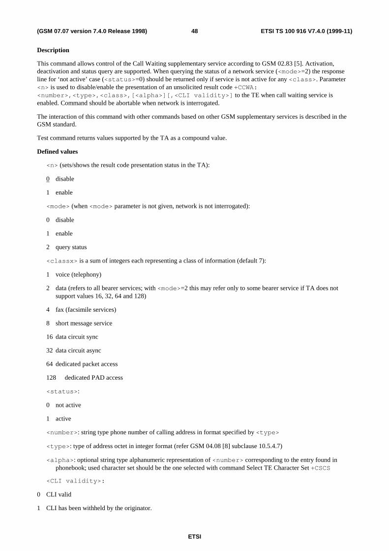
ETSI
ETSI TS 100 916 V7.4.0 (1999-11)48(GSM 07.07 version 7.4.0 Release 1998)
Description
This command allows control of the Call Waiting supplementary service according to GSM 02.83 [5]. Activation,deactivation and status query are supported. When querying the status of a network service (<mode>=2) the responseline for ‘not active’ case (<status>=0) should be returned only if service is not active for any <class>. Parameter<n> is used to disable/enable the presentation of an unsolicited result code +CCWA:<number>,<type>,<class>,[<alpha>][,<CLI validity>] to the TE when call waiting service isenabled. Command should be abortable when network is interrogated.
The interaction of this command with other commands based on other GSM supplementary services is described in theGSM standard.
Test command returns values supported by the TA as a compound value.
Defined values
<n> (sets/shows the result code presentation status in the TA):
0 disable
1 enable
<mode> (when <mode> parameter is not given, network is not interrogated):
0 disable
1 enable
2 query status
<classx> is a sum of integers each representing a class of information (default 7):
1 voice (telephony)
2 data (refers to all bearer services; with <mode>=2 this may refer only to some bearer service if TA does notsupport values 16, 32, 64 and 128)
4 fax (facsimile services)
8 short message service
16 data circuit sync
32 data circuit async
64 dedicated packet access
128 dedicated PAD access
<status>:
0 not active
1 active
<number>: string type phone number of calling address in format specified by <type>
<type>: type of address octet in integer format (refer GSM 04.08 [8] subclause 10.5.4.7)
<alpha>: optional string type alphanumeric representation of <number> corresponding to the entry found inphonebook; used character set should be the one selected with command Select TE Character Set +CSCS
<CLI validity>:
0 CLI valid
1 CLI has been withheld by the originator.
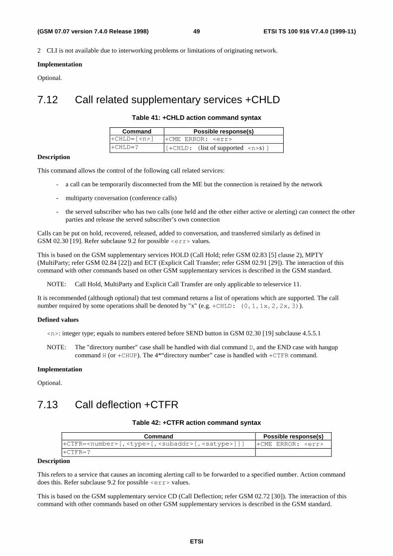
ETSI
ETSI TS 100 916 V7.4.0 (1999-11)49(GSM 07.07 version 7.4.0 Release 1998)
2 CLI is not available due to interworking problems or limitations of originating network.
Implementation
Optional.
7.12 Call related supplementary services +CHLD
Table 41: +CHLD action command syntax
Command Possible response(s)+CHLD=[<n>] +CME ERROR: <err>+CHLD=? [+CHLD: (list of supported <n>s)]
Description
This command allows the control of the following call related services:
- a call can be temporarily disconnected from the ME but the connection is retained by the network
- multiparty conversation (conference calls)
- the served subscriber who has two calls (one held and the other either active or alerting) can connect the otherparties and release the served subscriber’s own connection
Calls can be put on hold, recovered, released, added to conversation, and transferred similarly as defined inGSM 02.30 [19]. Refer subclause 9.2 for possible <err> values.
This is based on the GSM supplementary services HOLD (Call Hold; refer GSM 02.83 [5] clause 2), MPTY(MultiParty; refer GSM 02.84 [22]) and ECT (Explicit Call Transfer; refer GSM 02.91 [29]). The interaction of thiscommand with other commands based on other GSM supplementary services is described in the GSM standard.
NOTE: Call Hold, MultiParty and Explicit Call Transfer are only applicable to teleservice 11.
It is recommended (although optional) that test command returns a list of operations which are supported. The callnumber required by some operations shall be denoted by "x" (e.g. +CHLD: (0,1,1x,2,2x,3)).
Defined values
<n>: integer type; equals to numbers entered before SEND button in GSM 02.30 [19] subclause 4.5.5.1
NOTE: The "directory number" case shall be handled with dial command D, and the END case with hangupcommand H (or +CHUP). The 4*“directory number” case is handled with +CTFR command.
Implementation
Optional.
7.13 Call deflection +CTFR
Table 42: +CTFR action command syntax
Command Possible response(s)+CTFR=<number>[,<type>[,<subaddr>[,<satype>]]] +CME ERROR: <err>+CTFR=?
Description
This refers to a service that causes an incoming alerting call to be forwarded to a specified number. Action commanddoes this. Refer subclause 9.2 for possible <err> values.
This is based on the GSM supplementary service CD (Call Deflection; refer GSM 02.72 [30]). The interaction of thiscommand with other commands based on other GSM supplementary services is described in the GSM standard.

ETSI
ETSI TS 100 916 V7.4.0 (1999-11)50(GSM 07.07 version 7.4.0 Release 1998)
NOTE: Call Deflection is only applicable to teleservice 11.
Defined values
<number>: string type phone number of format specified by <type>
<type>: type of address octet in integer format (refer GSM 04.08 [8] subclause 10.5.4.7); default 145 whendialling string includes international access code character "+", otherwise 129
<subaddr>: string type subaddress of format specified by <satype>
<satype>: type of subaddress octet in integer format (refer GSM 04.08 [8] subclause 10.5.4.8); default 128
Implementation
Optional.
7.14 Unstructured supplementary service data +CUSD
Table 43: +CUSD parameter command syntax
Command Possible response(s)+CUSD=[<n>[,<str>[,<dcs>]]] +CME ERROR: <err>+CUSD? +CUSD: <n>+CUSD=? +CUSD: (list of supported <n>s)
Description
This command allows control of the Unstuctured Supplementary Service Data (USSD) according to GSM 02.90 [23].Both network and mobile initiated operations are supported. Parameter <n> is used to disable/enable the presentation ofan unsolicited result code (USSD response from the network, or network initiated operation) +CUSD:<m>[,<str>,<dcs>] to the TE. In addition, value <n>=2 is used to cancel an ongoing USSD session.
When <str> is given, a mobile initiated USSD-string or a response USSD-string to a network initiated operation issent to the network. The response USSD-string from the network is returned in a subsequent unsolicited +CUSD resultcode.
NOTE: In case of successful mobile initiated operation, TA implemented according to a version prior to 6 of thisstandard, waits the USSD response from the network and sends it to the TE before the final result code.This will block the AT command interface for the period of the operation. Such TA does not support <n>value 2.
The interaction of this command with other commands based on other GSM supplementary services is described in theGSM standard.
Test command returns values supported by the TA as a compound value.
Defined values
<n>:
0 disable the result code presentation in the TA
1 enable the result code presentation in the TA
2 cancel session (not applicable to read command response)
<str>: string type USSD-string (when <str> parameter is not given, network is not interrogated):
- if <dcs> indicates that GSM 03.38 [25] default alphabet is used:
- if TE character set other than "HEX" (refer command Select TE Character Set +CSCS): ME/TAconverts GSM alphabet into current TE character set according to rules of GSM 07.05 [24] Annex A

ETSI
ETSI TS 100 916 V7.4.0 (1999-11)51(GSM 07.07 version 7.4.0 Release 1998)
- if TE character set is "HEX": ME/TA converts each 7-bit character of GSM alphabet into two IRAcharacter long hexadecimal number (e.g. character Π (GSM 23) is presented as 17 (IRA 49 and 55))
- if <dcs> indicates that 8-bit data coding scheme is used: ME/TA converts each 8-bit octet into two IRAcharacter long hexadecimal number (e.g. octet with integer value 42 is presented to TE as two characters2A (IRA 50 and 65))
<dcs>: GSM 03.38 [25] Cell Broadcast Data Coding Scheme in integer format (default 0)
<m>:
0 no further user action required (network initiated USSD-Notify, or no further information needed after mobileinitiated operation)
1 further user action required (network initiated USSD-Request, or further information needed after mobileinitiated operation)
2 USSD terminated by network
3 other local client has responded
4 operation not supported
5 network time out
Implementation
Optional.
7.15 Advice of Charge +CAOC
Table 44: +CAOC parameter command syntax
Command Possible response(s)+CAOC[=<mode>] [+CAOC: <ccm>]
+CME ERROR: <err>+CAOC? +CAOC: <mode>+CAOC=? [+CAOC: (list of supported <mode>s]
Description
This refers to Advice of Charge supplementary service (GSM 02.24 [26] and GSM 02.86 [27]) that enables subscriberto get information about the cost of calls. With <mode>=0, the execute command returns the current call meter valuefrom the ME.
If $(AT R97)$ is supported, the command also includes the possibility to enable an unsolicited event reporting of theCCM information. The unsolicited result code +CCCM: <ccm> is sent when the CCM value changes, but not more thatevery 10 seconds. Deactivation of the unsolicited event reporting is made with the same command.
Refer subclause 9.2 for possible <err> values.
NOTE: Advice of Charge values stored in the SIM (ACM, ACMmax, PUCT) can be accessed with generic orrestricted SIM access command (+CSIM or +CRSM)). If $(AT R97)$ is supported those values can bemore readily accessed with commands +CACM, +CAMM and +CPUC.
If $(AT R97)$ is supported, the Read command indicates whether the unsolicited reporting is activated or not. Readcommand is available when the unsolicited result code is supported.
It is recommended (although optional) that the test command returns the supported mode values.
Defined values
<mode>: $(AT R97)$
0 query CCM value

ETSI
ETSI TS 100 916 V7.4.0 (1999-11)52(GSM 07.07 version 7.4.0 Release 1998)
1 deactivate the unsolicited reporting of CCM value
2 activate the unsolicited reporting of CCM value
<ccm>: string type; three bytes of the current call meter value in hexadecimal format (e.g. "00001E" indicatesdecimal value 30); value is in home units and bytes are similarly coded as ACMmax value in the SIM
Implementation
Optional.
7.16 Supplementary service notifications +CSSN
Table 45: +CSSN parameter command syntax
Command Possible response(s)+CSSN=[<n>[,<m>]]+CSSN? +CSSN: <n>,<m>+CSSN=? +CSSN: (list of supported <n>s),(list of supported <m>s)
Description
This command refers to supplementary service related network initiated notifications. The set command enables/disablesthe presentation of notification result codes from TA to TE.
When <n>=1 and a supplementary service notification is received after a mobile originated call setup, intermediateresult code +CSSI: <code1>[,<index>] is sent to TE before any other MO call setup result codes presented inthis TS or in V.25ter [14]. When several different <code1>s are received from the network, each of them shall have itsown +CSSI result code.
When <m>=1 and a supplementary service notification is received during a mobile terminated call setup or during a call,or when a forward check supplementary service notification is received, unsolicited result code +CSSU:<code2>[,<index>[,<number>,<type>[,<subaddr>,<satype>]]] is sent to TE. In case of MT callsetup, result code is sent after every +CLIP result code (refer command "Calling line identification presentation+CLIP") and when several different <code2>s are received from the network, each of them shall have its own +CSSUresult code.
Test command returns values supported by the TA as a compound value.
Defined values
<n> (parameter sets/shows the +CSSI result code presentation status in the TA):
0 disable
1 enable
<m> (parameter sets/shows the +CSSU result code presentation status in the TA):
0 disable
1 enable
<code1> (it is manufacturer specific, which of these codes are supported):
0 unconditional call forwarding is active
1 some of the conditional call forwardings are active
2 call has been forwarded
3 call is waiting
4 this is a CUG call (also <index> present)

ETSI
ETSI TS 100 916 V7.4.0 (1999-11)53(GSM 07.07 version 7.4.0 Release 1998)
5 outgoing calls are barred
6 incoming calls are barred
7 CLIR suppression rejected
8 call has been deflected
<index>: refer "Closed user group +CCUG"
<code2> (it is manufacturer specific, which of these codes are supported):
0 this is a forwarded call (MT call setup)
1 this is a CUG call (also <index> present) (MT call setup)
2 call has been put on hold (during a voice call)
3 call has been retrieved (during a voice call)
4 multiparty call entered (during a voice call)
5 call on hold has been released (this is not a SS notification) (during a voice call)
6 forward check SS message received (can be received whenever)
7 call is being connected (alerting) with the remote party in alerting state in explicit call transfer operation (during avoice call)
8 call has been connected with the other remote party in explicit call transfer operation (also number andsubaddress parameters may be present) (during a voice call or MT call setup)
9 this is a deflected call (MT call setup)
<number>: string type phone number of format specified by <type>
<type>: type of address octet in integer format (refer GSM 04.08 [8] subclause 10.5.4.7)
<subaddr>: string type subaddress of format specified by <satype>
<satype>: type of subaddress octet in integer format (refer GSM 04.08 [8] subclause 10.5.4.8)
Implementation
Optional.
7.17 List current calls +CLCC
Table 46: +CLCC action command syntax
Command Possible response(s)+CLCC [+CLCC: <id1>,<dir>,<stat>,<mode>,<mpty>[,
<number>,<type>[,<alpha>]][<CR><LF>+CLCC: <id2>,<dir>,<stat>,<mode>,<mpty>[,<number>,<type>[,<alpha>]][...]]]+CME ERROR: <err>
+CLCC=?
Description
Returns list of current calls of ME. If command succeeds but no calls are available, no information response is sent toTE. Refer subclause 9.2 for possible <err> values.
Defined values

ETSI
ETSI TS 100 916 V7.4.0 (1999-11)54(GSM 07.07 version 7.4.0 Release 1998)
<idx>: integer type; call identification number as described in GSM 02.30 [19] subclause 4.5.5.1; this number canbe used in +CHLD command operations
<dir>:
0 mobile originated (MO) call
1 mobile terminated (MT) call
<stat> (state of the call):
0 active
1 held
2 dialing (MO call)
3 alerting (MO call)
4 incoming (MT call)
5 waiting (MT call)
<mode> (bearer/teleservice):
0 voice
1 data
2 fax
3 voice followed by data, voice mode
4 alternating voice/data, voice mode
5 alternating voice/fax, voice mode
6 voice followed by data, data mode
7 alternating voice/data, data mode
8 alternating voice/fax, fax mode
9 unknown
<mpty>:
0 call is not one of multiparty (conference) call parties
1 call is one of multiparty (conference) call parties
<number>: string type phone number in format specified by <type>
<type>: type of address octet in integer format (refer GSM 04.08 [8] subclause 10.5.4.7)
<alpha>: string type alphanumeric representation of <number> corresponding to the entry found in phonebook;used character set should be the one selected with command Select TE Character Set +CSCS
Implementation
Optional. Recommended when +CHLD command is implemented.

ETSI
ETSI TS 100 916 V7.4.0 (1999-11)55(GSM 07.07 version 7.4.0 Release 1998)
7.18 Preferred operator list +CPOL $(AT R97)$
Table 47: +CPOL parameter command syntax
Command Possible response(s)+CPOL=[<index>][,<format>[,<oper>]]
+CME ERROR: <err>
+CPOL? +CPOL: <index1>,<format>,<oper1>[<CR><LF>+CPOL: <index2>,<format>,<oper2>[...]]+CME ERROR: <err>
+CPOL=? +CPOL: (list of supported <index>s),(list of supported<format>s)+CME ERROR: <err>
Description
This command is used to edit the SIM preferred list of networks. Execute command writes an entry in the SIM list ofpreferred operators (EFPLMNsel). If <index> is given but <oper> is left out, entry is deleted. If <oper> is given but<index> is left out, <oper> is put in the next free location. If only <format> is given, the format of the <oper> inthe read command is changed. Refer subclause 9.2 for possible <err> values.
NOTE: ME may also update this list automatically when new networks are selected.
Read command returns all used entries from the SIM list of preferred operators.
Test command returns the whole index range supported by the SIM.
Defined values
<indexn>: integer type; the order number of operator in the SIM preferred operator list
<format>:
0 long format alphanumeric <oper>
1 short format alphanumeric <oper>
2 numeric <oper>
<opern>: string type; <format> indicates if the format is alphanumeric or numeric (see +COPS)
Implementation
Optional.
7.19 Read operator names +COPN $(AT R97)$
Table 48: +COPN action command syntax
Command Possible response(s)+COPN +COPN: <numeric1>,<alpha1>
[<CR><LF>+COPN: <numeric2>,<alpha2>[...]]+CME ERROR: <err>
+COPN=?
Description
Execute command returns the list of operator names from the ME. Each operator code <numericn> that has analphanumeric equivalent <alphan> in the ME memory shall be returned. Refer subclause 9.2 for possible <err>values.
Defined values

ETSI
ETSI TS 100 916 V7.4.0 (1999-11)56(GSM 07.07 version 7.4.0 Release 1998)
<numericn>: string type; operator in numeric format (see +COPS)
<alphan>: string type; operator in long alphanumeric format (see +COPS)
Implementation
Optional.
7.20 Informative examplesThis subclause includes all the GSM supplementary service related commands, additional commands to lock ME andSIM capabilities, and commands to check the network registration status.
An example where MSISDNs of a ME are queried, calls are forwarded to different numbers when mobile is busy (CFB)or when it does not answer (CFNRy). The status of CFNRy is read:
AT+CNUM+CNUM: ,"+358501234567",145,,4 (voice number)OKAT+CCFC=1,1,"931123456" (enable CFB)OKAT+CCFC=2,1,"921654321" (enable CFNRy)OKAT+CCFC=1,2 (query CFNRy)+CCFC: 1,7,"+35821654321",145,,,20 (forward after 20 seconds)OK
An example of Call Waiting (+CCWA), Call Related Supplementary Services (+CHLD), and Connected LineIdentification Presentation (+COLP) usage:
AT+CCWA=1,1;+COLP=1 (enable call waiting and COLP result codes)OKATD9311234567; (originate a voice call)+COLP: "+358311234567",145OK...conversation...+CCWA: "+358317654321",145 (another call is waiting)AT+CHLD=2 (put first call on hold and answer the second one)OK...conversation...AT+CHLD=1 (release the second (active) call and recover the first (held) call)OKATH (release the first call)OK
Call barring supplementary services are combined in one command, Facility Lock (+CLCK), which is also used torestrict ME and SIM functionality Some of the facilities require a password when enabled or disabled. An additionalcommand, Change Password (+CPWD), is defined for changing the password of different barring and restrictionfacilities. An example where locking status of outgoing international calls is interrogated and then barred, and thepassword of the SIM card lock (Personal Identity Number, PIN) is changed:
AT+CLCK="OI",2+CLCK: 0,7OKAT+CLCK="OI",1,"1234"OKAT+CPWD="SC","4321","1234"OK
Operator Selection (+COPS) command is used for querying the status of all GSM operators detected in the area, andswitching between operators.
Following example illustrates a network selection sequence in Finland. Two operators are found, the status of Tele isunknown and Radiolinja is currently selected. Read command shows that automatic selection mode is on and thatRadiolinja is selected. Then an attempt is made to access Tele, but it is denied (shown by +CME ERROR).
AT+COPS=?+COPS: (2,"RADIOLINJA","RL","24405"),(0,"TELE","TELE","24491")OKAT+COPS?+COPS: 0,0,"RADIOLINJA"

ETSI
ETSI TS 100 916 V7.4.0 (1999-11)57(GSM 07.07 version 7.4.0 Release 1998)
OKAT+COPS=1,0,"TELE"+CME ERROR: 3
When a terminal wanders between countries (i.e. networks), an application may follow this e.g. with the followingscenario:
AT+CREG=1 (enable +CREG: <stat> unsolicited result code)OKAT+CREG?+CREG: 1,1 (ME is registered in home PLMN)OKAT+COPS=3,2;+COPS?;+COPS=3,0;+COPS?+COPS: 0,2,"24405" (get the country...+COPS: 0,0,"RADIOLINJA" ...and operator name)OK...user wanders to another PLMN...+CREG: 2 (deregistered, roaming ongoing)+CREG: 5 (registered again, not home PLMN)AT+COPS=3,2;+COPS?;+COPS=3,0;+COPS?+COPS: 0,2,"24001" (get the country...+COPS: 0,0,"TELIA MOBITEL" ...and operator name)OK...user loses connection, no other PLMNs around...+CREG: 0
8 Mobile Equipment control and status commandsThis clause includes commands for ME power, keypad, display and indicator handling. Also commands for selecting,reading and writing of phonebooks, and setting real-time clock facilities are specified. Two commands are specified foraccessing SIM database records in a general way.
Figure 7 illustrates the effect of these commands. Command Phone Activity Status +CPAS indicates the current generalactivity status of the ME. Command Set Phone Functionality +CFUN is used to set the ME to different powerconsumption states. Command Enter PIN +CPIN is used to enter ME passwords which are needed before any otherfunctionality of the ME can be used (e.g. SIM PIN, PUK). Commands Generic SIM Access +CSIM and Restricted SIMAccess +CRSM can be used to access all data in SIM. Commands Battery Charge +CBC and Signal Quality +CSQ aresame as in TIA IS-135 [16] and they are used to query the battery charge of the ME and the current RSSI of the ME.Command Mobile Equipment Control Mode +CMEC is used to select the controlling unit of ME keypad, display andindicators. Controlling commands for the TE are Keypad Emulation +CKPD, Display Control +CDIS and IndicatorControl +CIND. If corresponding event reporting is enabled with command Mobile Equipment Event Reporting+CMER, +CKEV is the result code of a keypad event, +CDEV is the result code of a display event, and +CIEV is theresult code of an indicator event. Phonebook commands are Select Phonebook Memory Storage +CPBS, ReadPhonebook Entries +CPBR, Find Phonebook Entries +CPBF and Write Phonebook Entry +CPBW. Additional commandClock +CCLK can be used to control the real-time clock of the ME if available. Command Alarm +CALA sets possiblealarm clock facilities of the ME.

ETSI
ETSI TS 100 916 V7.4.0 (1999-11)58(GSM 07.07 version 7.4.0 Release 1998)
KEYPAD
ME TA
+CKPD
+CMER
+CKEV
+CIEV
+CDIS
+CIND
DISPLAY
INDICATORS
+CDEV
+CMEC
PHONE-BOOKS
+CPBS
+CPBW
+CPBR, +CPBF
TE
+CFUN
+CPAS
+CCLK, +CALA
+CBC
+CSQ
+CPIN, +CSIM, +CRSMSIMIF,PASSWORDFACILITIES
Figure 7: Mobile equipment control and status commands
8.1 Phone activity status +CPAS
Table 49: +CPAS action command syntax
Command Possible response(s)+CPAS +CPAS: <pas>
+CME ERROR: <err>+CPAS=? +CPAS: (list of supported <pas>s)
+CME ERROR: <err>
Description
Execution command returns the activity status <pas> of the ME. It can be used to interrogate the ME before requestingaction from the phone. Refer subclause 9.2 for possible <err> values.
Test command returns values supported by the ME as a compound value.
Defined values
<pas>:
0 ready (ME allows commands from TA/TE)
1 unavailable (ME does not allow commands from TA/TE)
2 unknown (ME is not guaranteed to respond to instructions)

ETSI
ETSI TS 100 916 V7.4.0 (1999-11)59(GSM 07.07 version 7.4.0 Release 1998)
3 ringing (ME is ready for commands from TA/TE, but the ringer is active)
4 call in progress (ME is ready for commands from TA/TE, but a call is in progress)
5 asleep (ME is unable to process commands from TA/TE because it is in a low functionality state)
also all other values below 128 are reserved by this TS
Implementation
Mandatory when ME can be operated from TE (refer subclause "Mobile Equipment control mode +CMEC").
8.2 Set phone functionality +CFUN
Table 50: +CFUN parameter command syntax
Command Possible response(s)+CFUN=[<fun>[,<rst>]] +CME ERROR: <err>+CFUN? +CFUN: <fun>
+CME ERROR: <err>+CFUN=? +CFUN: (list of supported <fun>s), (list of supported <rst>s)
+CME ERROR: <err>
Description
Set command selects the level of functionality <fun> in the ME. Level "full functionality" is where the highest level ofpower is drawn. "Minimum functionality" is where minimum power is drawn. Level of functionality between these mayalso be specified by manufacturers. When supported by manufacturers, ME resetting with <rst> parameter may beutilized. Refer subclause 9.2 for possible <err> values.
NOTE: It is manufacturer specific does this command affect network registration. Command Operator Selection+COPS is used to force registration/deregistration.
Test command returns values supported by the ME as a compound value.
Defined values
<fun>:
0 minimum functionality
1 full functionality
2 disable phone transmit RF circuits only
3 disable phone receive RF circuits only
4 disable phone both transmit and receive RF circuits
5...127reserved for manufacturers as intermediate states between full and minimum functionality
<rst>:
0 do not reset the ME before setting it to <fun> power level
NOTE: This shall be always default when <rst> is not given.
1 reset the ME before setting it to <fun> power level
Implementation
Optional.
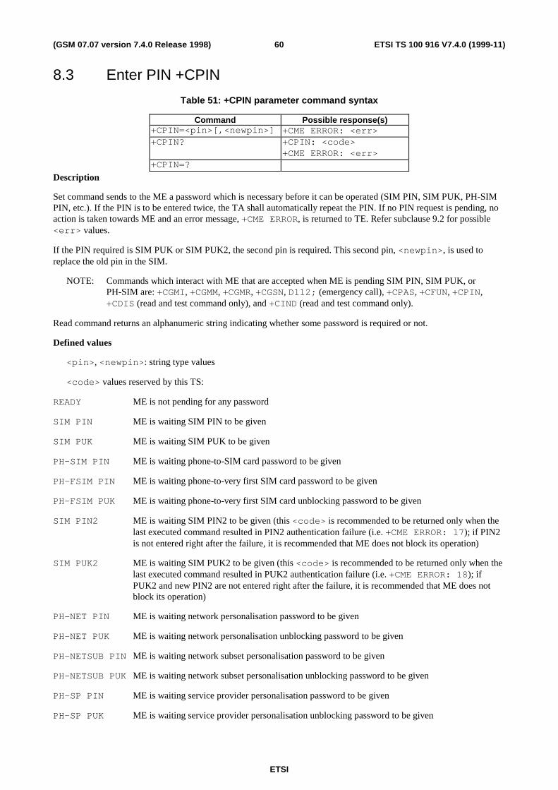
ETSI
ETSI TS 100 916 V7.4.0 (1999-11)60(GSM 07.07 version 7.4.0 Release 1998)
8.3 Enter PIN +CPIN
Table 51: +CPIN parameter command syntax
Command Possible response(s)+CPIN=<pin>[,<newpin>] +CME ERROR: <err>+CPIN? +CPIN: <code>
+CME ERROR: <err>+CPIN=?
Description
Set command sends to the ME a password which is necessary before it can be operated (SIM PIN, SIM PUK, PH-SIMPIN, etc.). If the PIN is to be entered twice, the TA shall automatically repeat the PIN. If no PIN request is pending, noaction is taken towards ME and an error message, +CME ERROR, is returned to TE. Refer subclause 9.2 for possible<err> values.
If the PIN required is SIM PUK or SIM PUK2, the second pin is required. This second pin, <newpin>, is used toreplace the old pin in the SIM.
NOTE: Commands which interact with ME that are accepted when ME is pending SIM PIN, SIM PUK, orPH-SIM are: +CGMI, +CGMM, +CGMR, +CGSN, D112; (emergency call), +CPAS, +CFUN, +CPIN,+CDIS (read and test command only), and +CIND (read and test command only).
Read command returns an alphanumeric string indicating whether some password is required or not.
Defined values
<pin>, <newpin>: string type values
<code> values reserved by this TS:
READY ME is not pending for any password
SIM PIN ME is waiting SIM PIN to be given
SIM PUK ME is waiting SIM PUK to be given
PH-SIM PIN ME is waiting phone-to-SIM card password to be given
PH-FSIM PIN ME is waiting phone-to-very first SIM card password to be given
PH-FSIM PUK ME is waiting phone-to-very first SIM card unblocking password to be given
SIM PIN2 ME is waiting SIM PIN2 to be given (this <code> is recommended to be returned only when thelast executed command resulted in PIN2 authentication failure (i.e. +CME ERROR: 17); if PIN2is not entered right after the failure, it is recommended that ME does not block its operation)
SIM PUK2 ME is waiting SIM PUK2 to be given (this <code> is recommended to be returned only when thelast executed command resulted in PUK2 authentication failure (i.e. +CME ERROR: 18); ifPUK2 and new PIN2 are not entered right after the failure, it is recommended that ME does notblock its operation)
PH-NET PIN ME is waiting network personalisation password to be given
PH-NET PUK ME is waiting network personalisation unblocking password to be given
PH-NETSUB PIN ME is waiting network subset personalisation password to be given
PH-NETSUB PUK ME is waiting network subset personalisation unblocking password to be given
PH-SP PIN ME is waiting service provider personalisation password to be given
PH-SP PUK ME is waiting service provider personalisation unblocking password to be given

ETSI
ETSI TS 100 916 V7.4.0 (1999-11)61(GSM 07.07 version 7.4.0 Release 1998)
PH-CORP PIN ME is waiting corporate personalisation password to be given
PH-CORP PUK ME is waiting corporate personalisation unblocking password to be given
Implementation
Mandatory for ME not supporting the +CKPD command and supporting AT commands only.
8.4 Battery charge +CBC
Table 52: +CBC action command syntax
Command Possible response(s)+CBC +CBC: <bcs>,<bcl>
+CME ERROR: <err>+CBC=? +CBC: (list of supported <bcs>s),(list of supported <bcl>s)
Description
Execution command returns battery connection status <bcs> and battery charge level <bcl> of the ME. Refersubclause 9.2 for possible <err> values.
Test command returns values supported by the TA as compound values.
Defined values
<bcs>:
0 ME is powered by the battery
1 ME has a battery connected, but is not powered by it
2 ME does not have a battery connected
3 Recognized power fault, calls inhibited
<bcl>:
0 battery is exhausted, or ME does not have a battery connected
1...100battery has 1-100 percent of capacity remaining
Implementation
Optional.
8.5 Signal quality +CSQ
Table 53: +CSQ action command syntax
Command Possible response(s)+CSQ +CSQ: <rssi>,<ber>
+CME ERROR: <err>+CSQ=? +CSQ: (list of supported <rssi>s),(list of supported <ber>s)
Description
Execution command returns received signal strength indication <rssi> and channel bit error rate <ber> from the ME.Refer subclause 9.2 for possible <err> values.
Test command returns values supported by the TA as compound values.
Defined values
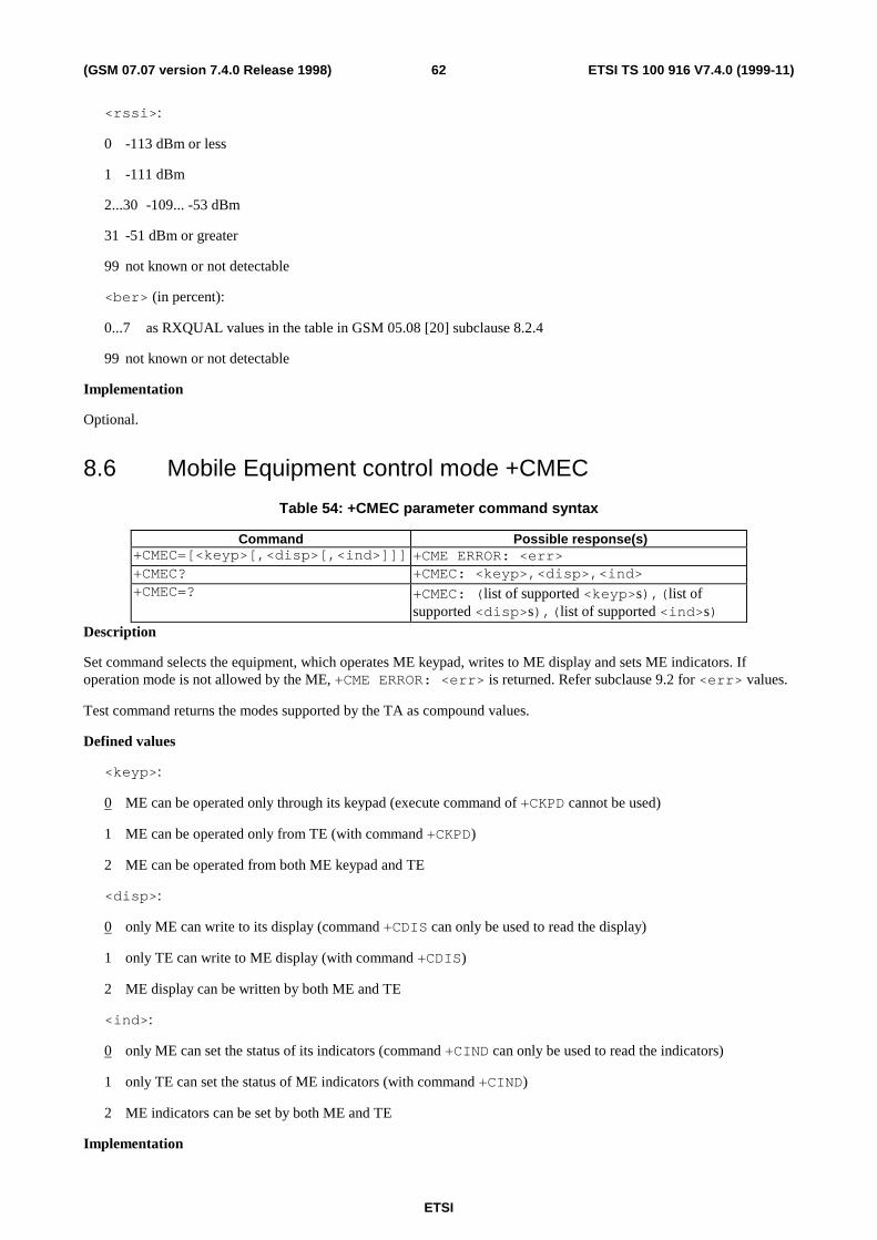
ETSI
ETSI TS 100 916 V7.4.0 (1999-11)62(GSM 07.07 version 7.4.0 Release 1998)
<rssi>:
0 -113 dBm or less
1 -111 dBm
2...30 -109... -53 dBm
31 -51 dBm or greater
99 not known or not detectable
<ber> (in percent):
0...7 as RXQUAL values in the table in GSM 05.08 [20] subclause 8.2.4
99 not known or not detectable
Implementation
Optional.
8.6 Mobile Equipment control mode +CMEC
Table 54: +CMEC parameter command syntax
Command Possible response(s)+CMEC=[<keyp>[,<disp>[,<ind>]]] +CME ERROR: <err>+CMEC? +CMEC: <keyp>,<disp>,<ind>+CMEC=? +CMEC: (list of supported <keyp>s),(list of
supported <disp>s),(list of supported <ind>s)
Description
Set command selects the equipment, which operates ME keypad, writes to ME display and sets ME indicators. Ifoperation mode is not allowed by the ME, +CME ERROR: <err> is returned. Refer subclause 9.2 for <err> values.
Test command returns the modes supported by the TA as compound values.
Defined values
<keyp>:
0 ME can be operated only through its keypad (execute command of +CKPD cannot be used)
1 ME can be operated only from TE (with command +CKPD)
2 ME can be operated from both ME keypad and TE
<disp>:
0 only ME can write to its display (command +CDIS can only be used to read the display)
1 only TE can write to ME display (with command +CDIS)
2 ME display can be written by both ME and TE
<ind>:
0 only ME can set the status of its indicators (command +CIND can only be used to read the indicators)
1 only TE can set the status of ME indicators (with command +CIND)
2 ME indicators can be set by both ME and TE
Implementation

ETSI
ETSI TS 100 916 V7.4.0 (1999-11)63(GSM 07.07 version 7.4.0 Release 1998)
Mandatory when any of keypad, display or indicator commands is implemented.
8.7 Keypad control +CKPD
Table 55: +CKPD action command syntax
Command Possible response(s)+CKPD=<keys>[,<time>[,<pause>]] +CME ERROR: <err>+CKPD=?
Description
Execution command emulates ME keypad by giving each keystroke as a character in a string <keys>. <time>*0.1seconds is the time to stroke each key and <pause>*0.1 seconds is the length of pause between two strokes. Ifemulating fails in an ME error, +CME ERROR: <err> is returned. Refer subclause 9.2 for <err> values. Thiscommand should be accepted (OK returned) before actually starting to press the keys. Thus unsolicited result codes ofkey pressings and display events can be returned (refer subclause "Mobile Equipment event reporting +CMER").
Defined values
<keys>: string of characters representing keys as listed in the following table (based on PCCA STD-101 Annextable I-3). Colon character (IRA 58) followed by one character can be used to indicate a manufacturer specifickey not listed here. All characters from a semicolon character (IRA 59) to the next single semicolon character aretreated as alpha entries and are not converted to key equivalents. All semicolon characters inside alpha entriesshould be duplicated in the TE and stripped to one before entering to the ME. Pause character (IRA 87 or 119)can be used to pause between key pressings for a time specified by <pause>. All IRA values not listed here arereserved.
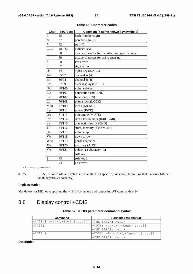
ETSI
ETSI TS 100 916 V7.4.0 (1999-11)64(GSM 07.07 version 7.4.0 Release 1998)
Table 56: Character codes
Char IRA (dec) Comment (+ some known key symbols)# 35 hash (number sign)% 37 percent sign (P)* 42 star (*)0... 9 48... 57 number keys: 58 escape character for manufacturer specific keys; 59 escape character for string entering< 60 left arrow> 62 right arrow@ 64 alpha key (α/ABC)A/a 65/97 channel A (A)B/b 66/98 channel B (B)C/c 67/99 clear display (C/CLR)D/d 68/100 volume downE/e 69/101 connection end (END)F/f 70/102 function (FCN)L/l 76/108 phone lock (LOCK)M/m 77/109 menu (MENU)P/p 80/112 power (PWR)Q/q 81/113 quiet/mute (MUTE)R/r 82/114 recall last number (R/RCL/MR)S/s 83/115 connection start (SEND)T/t 84/116 store/ memory (STO/M/M+)U/u 85/117 volume upV/v 86/118 down arrowW/w 87/119 pause characterX/x 88/120 auxiliary (AUX)Y/y 89/121 delete last character (C)[ 91 soft key 1] 93 soft key 2^ 94 up arrow
<time>, <pause>:
0...255 0... 25.5 seconds (default values are manufacturer specific, but should be so long that a normal ME canhandle keystrokes correctly)
Implementation
Mandatory for ME not supporting the +CPIN command and supporting AT commands only.
8.8 Display control +CDIS
Table 57: +CDIS parameter command syntax
Command Possible response(s)+CDIS=[<text>[,<text>[,...]]] +CME ERROR: <err>+CDIS? +CDIS: <text>[,<text>[,...]]
+CME ERROR: <err>+CDIS=? +CDIS: <length>[,<length>[,...]]
+CME ERROR: <err>
Description

ETSI
ETSI TS 100 916 V7.4.0 (1999-11)65(GSM 07.07 version 7.4.0 Release 1998)
Set command is used to write the contents of ME text type display elements. An element can consist of one character orseveral characters. The order of element parameters <text> should follow the rule: first is the element in upper leftcorner, second is the next element to the right and so on. The last element is the element in lower right corner. Thenumber of elements is ME specific. If ME does not allow writing to its display or ME is not currently reachable, +CMEERROR: <err> is returned. Refer subclause 9.2 for <err> values. If certain element is not writable, setting of itshould be ignored. If element parameter is empty field, element shall remain in the previous value.
NOTE: This command cannot be used to write to a display which sum of element lengths exceed the length of thecommand line buffer of the TA.
Read command returns the contents of ME display elements. If <text> field is empty (not empty string), ME does notallow the reading of corresponding element. If ME is not currently reachable, +CME ERROR: <err> is returned.Refer subclause 9.2 for <err> values.
Test command returns maximum length of each display element. If ME does not offer the length of elements,<length> fields should be empty. If ME is not currently reachable, +CME ERROR: <err> is returned. Refersubclause 9.2 for <err> values.
NOTE: ME manufacturer should offer the order and maximum length of elements.
Defined values
<text>: string type parameter using character set specified by command Select TE Character Set +CSCS
<length>: integer type parameter giving the maximum length of corresponding <text> parameter
Implementation
Optional.
8.9 Indicator control +CIND
Table 58: +CIND parameter command syntax
Command Possible response(s)+CIND=[<ind>[,<ind>[,...]]] +CME ERROR: <err>+CIND? +CIND: <ind>[,<ind>[,...]]
+CME ERROR: <err>+CIND=? +CIND: (<descr>,(list of supported
<ind>s)) [,(<descr>,(list of supported<ind>s))[,...]]+CME ERROR: <err>
Description
Set command is used to set the values of ME indicators. <ind> value 0 means that the indicator is off (or in state whichcan be identified as "off"-state), 1 means that indicator is on (or in a state which is more substantial than "off"-state), 2 ismore substantial than 1, and so on. If the indicator is a simple on/off style element, it has values 0 and 1. The number ofelements is ME specific. If ME does not allow setting of indicators or ME is not currently reachable, +CME ERROR:<err> is returned. Refer subclause 9.2 for <err> values. If certain indicator is not writable, setting of it should beignored. If parameter is empty field, indicator shall remain in the previous value.
Read command returns the status of ME indicators. If ME is not currently reachable, +CME ERROR: <err> isreturned. Refer subclause 9.2 for <err> values.
Test command returns pairs, where string value <descr> is a maximum 16 character description of the indicator andcompound value is the allowed values for the indicator. If ME is not currently reachable, +CME ERROR: <err> isreturned. Refer subclause 9.2 for <err> values.
NOTE: ME manufacturer should offer the description of supported indicators not listed here and their valueranges and default values.
Defined values

ETSI
ETSI TS 100 916 V7.4.0 (1999-11)66(GSM 07.07 version 7.4.0 Release 1998)
<ind>: integer type value, which shall be in range of corresponding <descr>
<descr> values reserved by this TS and their <ind> ranges:
"battchg" battery charge level (0-5)
"signal" signal quality (0-5)
"service" service availability (0-1)
"sounder" sounder activity (0-1)
"message" message received (0-1)
"call" call in progress (0-1)
"vox" transmit activated by voice activity (0-1)
"roam" roaming indicator (0-1)
"smsfull" a short message memory storage in the MT has become full (1), or memory locations are available (0);i.e. the range is (0-1)
Implementation
Optional.
8.10 Mobile Equipment event reporting +CMER
Table 59: +CMER parameter command syntax
Command Possible response(s)+CMER=[<mode>[,<keyp>[,<disp>[,<ind>[,<bfr>]]]]]
+CME ERROR: <err>
+CMER? +CMER: <mode>,<keyp>,<disp>,<ind>,<bfr>+CMER=? +CMER: (list of supported <mode>s),(list of supported
<keyp>s),(list of supported <disp>s),(list of supported<ind>s),(list of supported <bfr>s)
Description
Set command enables or disables sending of unsolicited result codes from TA to TE in the case of key pressings, displaychanges, and indicator state changes. <mode> controls the processing of unsolicited result codes specified within thiscommand. <bfr> controls the effect on buffered codes when <mode> 1, 2 or 3 is entered. If setting is not supported bythe ME, +CME ERROR: <err> is returned. Refer subclause 9.2 for <err> values.
Test command returns the modes supported by the TA as compound values.
Defined values
<mode>:
0 buffer unsolicited result codes in the TA; if TA result code buffer is full, codes can be buffered in some otherplace or the oldest ones can be discarded
1 discard unsolicited result codes when TA-TE link is reserved (e.g. in on-line data mode); otherwise forward themdirectly to the TE
2 buffer unsolicited result codes in the TA when TA-TE link is reserved (e.g. in on-line data mode) and flush themto the TE after reservation; otherwise forward them directly to the TE
3 forward unsolicited result codes directly to the TE; TA-TE link specific inband technique used to embed resultcodes and data when TA is in on-line data mode

ETSI
ETSI TS 100 916 V7.4.0 (1999-11)67(GSM 07.07 version 7.4.0 Release 1998)
<keyp>:
0 no keypad event reporting
1 keypad event reporting using result code +CKEV: <key>,<press>. <key> indicates the key (refer IRAvalues defined in table in subclause "Keypad control +CKPD") and <press> if the key is pressed or released (1for pressing and 0 for releasing). Only those key pressings, which are not caused by +CKPD shall be indicated bythe TA to the TE.
NOTE: When this mode is enabled, corresponding result codes of all keys currently pressed should be flushed tothe TA regardless of <bfr> setting.
2 keypad event reporting using result code +CKEV: <key>,<press>. All key pressings shall be directed fromTA to TE.
NOTE: When this mode is enabled, corresponding result codes of all keys currently pressed should be flushed tothe TA regardless of <bfr> setting.
<disp>:
0 no display event reporting
1 display event reporting using result code +CDEV: <elem>,<text>. <elem> indicates the element ordernumber (as specified for +CDIS) and <text> is the new value of text element. Only those display events, whichare not caused by +CDIS shall be indicated by the TA to the TE. Character set used in <text> is as specifiedby command Select TE Character Set +CSCS
2 display event reporting using result code +CDEV: <elem>,<text>. All display events shall be directed fromTA to TE. Character set used in <text> is as specified by command Select TE Character Set +CSCS
<ind>:
0 no indicator event reporting
1 indicator event reporting using result code +CIEV: <ind>,<value>. <ind> indicates the indicator ordernumber (as specified for +CIND) and <value> is the new value of indicator. Only those indicator events, whichare not caused by +CIND shall be indicated by the TA to the TE
2 indicator event reporting using result code +CIEV: <ind>,<value>. All indicator events shall be directedfrom TA to TE
<bfr>:
0 TA buffer of unsolicited result codes defined within this command is cleared when <mode> 1...3 is entered
1 TA buffer of unsolicited result codes defined within this command is flushed to the TE when <mode> 1...3 isentered (OK response shall be given before flushing the codes)
Implementation
Mandatory when any of the keypad, display, or indicator result codes is implemented.
8.11 Select phonebook memory storage +CPBS
Table 60: +CPBS parameter command syntax
Command Possible response(s)+CPBS=<storage> +CME ERROR: <err>+CPBS? +CPBS: <storage>[,<used>,<total>]
+CME ERROR: <err>+CPBS=? +CPBS: (list of supported <storage>s)
Description

ETSI
ETSI TS 100 916 V7.4.0 (1999-11)68(GSM 07.07 version 7.4.0 Release 1998)
Set command selects phonebook memory storage <storage>, which is used by other phonebook commands. If settingfails in an ME error, +CME ERROR: <err> is returned. Refer subclause 9.2 for <err> values.
Read command returns currently selected memory, and when supported by manufacturer, number of used locations andtotal number of locations in the memory.
Test command returns supported storages as compound value.
Defined values
<storage> values reserved by this TS:
"DC" ME dialled calls list (+CPBW may not be applicable for this storage) $(AT R97)$
"EN" SIM (or ME) emergency number (+CPBW is not be applicable for this storage) $(AT R97)$
"FD" SIM fixdialling-phonebook
"LD" SIM last-dialling-phonebook
"MC" ME missed (unanswered received) calls list (+CPBW may not be applicable for this storage)
"ME" ME phonebook
"MT" combined ME and SIM phonebook
"ON" SIM (or ME) own numbers (MSISDNs) list (reading of this storage may be available through +CNUMalso) $(AT R97)$
"RC" ME received calls list (+CPBW may not be applicable for this storage) $(AT R97)$
"SM" SIM phonebook
"TA" TA phonebook
<used>: integer type value indicating the number of used locations in selected memory
<total>: integer type value indicating the total number of locations in selected memory
Implementation
Mandatory when phonebook read, find or write command, or direct dialling (refer subclause "Direct dialling fromphonebooks") is implemented.
8.12 Read phonebook entries +CPBR
Table 61: +CPBR action command syntax
Command Possible response(s)+CPBR=<index1>[,<index2>]
[+CPBR: <index1>,<number>,<type>,<text>[[...]<CR><LF>+CPBR: <index2>,<number>,<type>,<text>]]+CME ERROR: <err>
+CPBR=? +CPBR: (list of supported <index>s),[<nlength>],[<tlength>]+CME ERROR: <err>
Description
Execution command returns phonebook entries in location number range <index1>... <index2> from the currentphonebook memory storage selected with +CPBS. If <index2> is left out, only location <index1> is returned. Entryfields returned are location number <indexn>, phone number stored there <number> (of format <type>) and text<text> associated with the number. If all queried locations are empty (but available), no information text lines may bereturnedIf listing fails in an ME error, +CME ERROR: <err> is returned. Refer subclause 9.2 for <err> values.

ETSI
ETSI TS 100 916 V7.4.0 (1999-11)69(GSM 07.07 version 7.4.0 Release 1998)
Test command returns location range supported by the current storage as a compound value and the maximum lengths of<number> and <text> fields. In case of SIM storage, the lengths may not be available. If ME is not currentlyreachable, +CME ERROR: <err> is returned. Refer subclause 9.2 for <err> values.
Defined values
<index1>, <index2>, <index>: integer type values in the range of location numbers of phonebook memory
<number>: string type phone number of format <type>
<type>: type of address octet in integer format (refer GSM 04.08 [8] subclause 10.5.4.7)
<text>: string type field of maximum length <tlength>; character set as specified by command Select TECharacter Set +CSCS
<nlength>: integer type value indicating the maximum length of field <number>
<tlength>: integer type value indicating the maximum length of field <text>
Implementation
Optional.
8.13 Find phonebook entries +CPBF
Table 62: +CPBF action command syntax
Command Possible response(s)+CPBF=<findtext> [+CPBF: <index1>,<number>,<type>,<text>[[...]
<CR><LF>+CBPF: <index2>,<number>,<type>,<text>]]+CME ERROR: <err>
+CPBF=? +CPBF: [<nlength>],[<tlength>]+CME ERROR: <err>
Description
Execution command returns phonebook entries (from the current phonebook memory storage selected with +CPBS)which alphanumeric field start with string <findtext>. Entry fields returned are location number <indexn>, phonenumber stored there <number> (of format <type>) and text <text> associated with the number. If listing fails in anME error, +CME ERROR: <err> is returned. Refer subclause 9.2 for <err> values.
Test command returns the maximum lengths of <number> and <text> fields. In case of SIM storage, the lengths maynot be available. If ME is not currently reachable, +CME ERROR: <err> is returned. Refer subclause 9.2 for <err>values.
Defined values
<index1>, <index2>: integer type values in the range of location numbers of phonebook memory
<number>: string type phone number of format <type>
<type>: type of address octet in integer format (refer GSM 04.08 [8] subclause 10.5.4.7)
<findtext>, <text>: string type field of maximum length <tlength>; character set as specified by commandSelect TE Character Set +CSCS
<nlength>: integer type value indicating the maximum length of field <number>
<tlength>: integer type value indicating the maximum length of field <text>
Implementation
Optional.
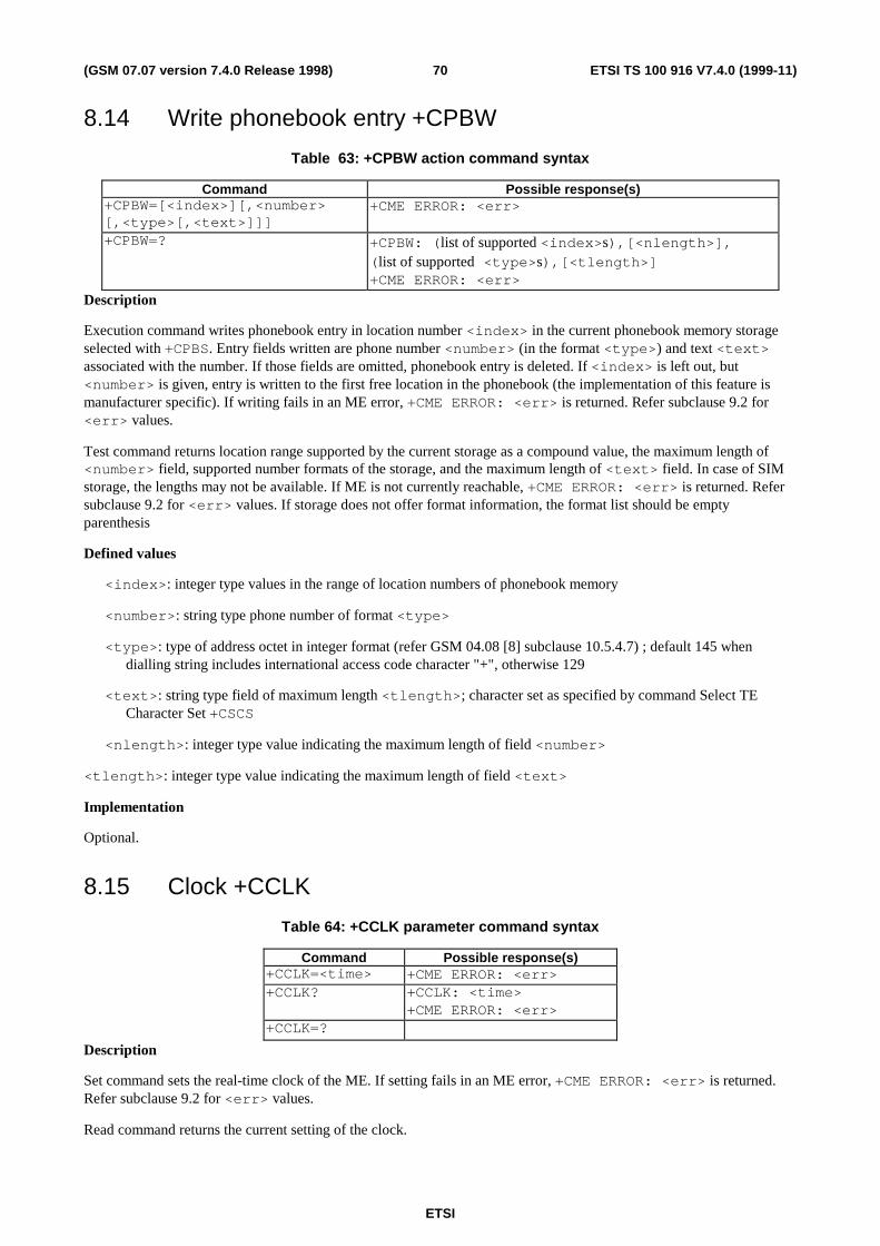
ETSI
ETSI TS 100 916 V7.4.0 (1999-11)70(GSM 07.07 version 7.4.0 Release 1998)
8.14 Write phonebook entry +CPBW
Table 63: +CPBW action command syntax
Command Possible response(s)+CPBW=[<index>][,<number>[,<type>[,<text>]]]
+CME ERROR: <err>
+CPBW=? +CPBW: (list of supported <index>s),[<nlength>],(list of supported <type>s),[<tlength>]+CME ERROR: <err>
Description
Execution command writes phonebook entry in location number <index> in the current phonebook memory storageselected with +CPBS. Entry fields written are phone number <number> (in the format <type>) and text <text>associated with the number. If those fields are omitted, phonebook entry is deleted. If <index> is left out, but<number> is given, entry is written to the first free location in the phonebook (the implementation of this feature ismanufacturer specific). If writing fails in an ME error, +CME ERROR: <err> is returned. Refer subclause 9.2 for<err> values.
Test command returns location range supported by the current storage as a compound value, the maximum length of<number> field, supported number formats of the storage, and the maximum length of <text> field. In case of SIMstorage, the lengths may not be available. If ME is not currently reachable, +CME ERROR: <err> is returned. Refersubclause 9.2 for <err> values. If storage does not offer format information, the format list should be emptyparenthesis
Defined values
<index>: integer type values in the range of location numbers of phonebook memory
<number>: string type phone number of format <type>
<type>: type of address octet in integer format (refer GSM 04.08 [8] subclause 10.5.4.7) ; default 145 whendialling string includes international access code character "+", otherwise 129
<text>: string type field of maximum length <tlength>; character set as specified by command Select TECharacter Set +CSCS
<nlength>: integer type value indicating the maximum length of field <number>
<tlength>: integer type value indicating the maximum length of field <text>
Implementation
Optional.
8.15 Clock +CCLK
Table 64: +CCLK parameter command syntax
Command Possible response(s)+CCLK=<time> +CME ERROR: <err>+CCLK? +CCLK: <time>
+CME ERROR: <err>+CCLK=?
Description
Set command sets the real-time clock of the ME. If setting fails in an ME error, +CME ERROR: <err> is returned.Refer subclause 9.2 for <err> values.
Read command returns the current setting of the clock.
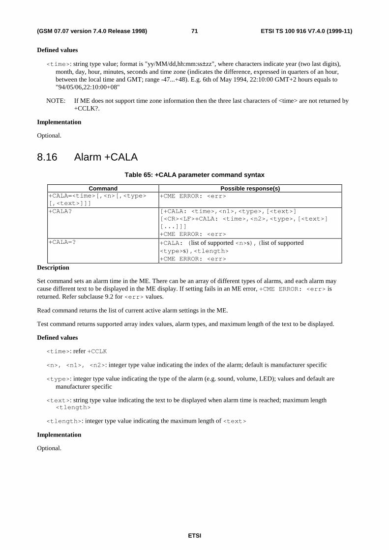
ETSI
ETSI TS 100 916 V7.4.0 (1999-11)71(GSM 07.07 version 7.4.0 Release 1998)
Defined values
<time>: string type value; format is "yy/MM/dd,hh:mm:ss±zz", where characters indicate year (two last digits),month, day, hour, minutes, seconds and time zone (indicates the difference, expressed in quarters of an hour,between the local time and GMT; range -47...+48). E.g. 6th of May 1994, 22:10:00 GMT+2 hours equals to"94/05/06,22:10:00+08"
NOTE: If ME does not support time zone information then the three last characters of <time> are not returned by+CCLK?.
Implementation
Optional.
8.16 Alarm +CALA
Table 65: +CALA parameter command syntax
Command Possible response(s)+CALA=<time>[,<n>[,<type>[,<text>]]]
+CME ERROR: <err>
+CALA? [+CALA: <time>,<n1>,<type>,[<text>][<CR><LF>+CALA: <time>,<n2>,<type>,[<text>][...]]]+CME ERROR: <err>
+CALA=? +CALA: (list of supported <n>s),(list of supported<type>s),<tlength>+CME ERROR: <err>
Description
Set command sets an alarm time in the ME. There can be an array of different types of alarms, and each alarm maycause different text to be displayed in the ME display. If setting fails in an ME error, +CME ERROR: <err> isreturned. Refer subclause 9.2 for <err> values.
Read command returns the list of current active alarm settings in the ME.
Test command returns supported array index values, alarm types, and maximum length of the text to be displayed.
Defined values
<time>: refer +CCLK
<n>, <n1>, <n2>: integer type value indicating the index of the alarm; default is manufacturer specific
<type>: integer type value indicating the type of the alarm (e.g. sound, volume, LED); values and default aremanufacturer specific
<text>: string type value indicating the text to be displayed when alarm time is reached; maximum length<tlength>
<tlength>: integer type value indicating the maximum length of <text>
Implementation
Optional.

ETSI
ETSI TS 100 916 V7.4.0 (1999-11)72(GSM 07.07 version 7.4.0 Release 1998)
8.17 Generic SIM access +CSIM
Table 66: +CSIM action command syntax
Command Possible response(s)+CSIM=<length>,<command> +CSIM: <length>,<response>
+CME ERROR: <err>+CSIM=?
Description
Set command transmits to the ME the <command> it then shall send as it is to the SIM. In the same manner the SIM<response> shall be sent back by the ME to the TA as it is. Refer subclause 9.2 for <err> values.
This command allows a direct control of the SIM by an distant application on the TE. The TE shall then take care ofprocessing SIM information within the frame specified by GSM.
NOTE: Compared to Restricted SIM Access command +CRSM, the definition of +CSIM allows TE to take morecontrol over the SIM-ME interface. The locking and unlocking of the interface may be done by a special<command> value or automatically by TA/ME (by interpreting <command> parameter). In case that TEapplication does not use the unlock command (or does not send a <command> causing automatic unlock)in a certain timeout value, ME may release the locking.
Defined values
<length> : integer type; length of the characters that are sent to TE in <command> or <response> (two timesthe actual length of the command or response)
<command> : command passed on by the ME to the SIM in the format as described in GSM 11.11 [28](hexadecimal character format; refer +CSCS)
<response> : response to the command passed on by the SIM to the ME in the format as described inGSM 11.11 [28] (hexadecimal character format; refer +CSCS)
Implementation
Optional.
8.18 Restricted SIM access +CRSM
Table 67: +CRSM action command syntax
Command Possible response(s)+CRSM=<command>[,<fileid>[,<P1>,<P2>,<P3>[,<data>]]]
+CRSM: <sw1>,<sw2>[,<response>]+CME ERROR: <err>
+CRSM=?
Description
By using this command instead of Generic SIM Access +CSIM TE application has easier but more limited access to theSIM database. Set command transmits to the ME the SIM <command> and its required parameters. ME handlesinternally all SIM-ME interface locking and file selection routines. As response to the command, ME sends the actualSIM information parameters and response data. ME error result code +CME ERROR may be returned when thecommand cannot be passed to the SIM, but failure in the execution of the command in the SIM is reported in <sw1>and <sw2> parameters. Refer to subclause 9.2 for <err> values.
Coordination of command requests to SIM and the ones issued by GSM application inside the ME is implementationdependent. However the TE should be aware of the precedence of the GSM application commands to the TE commands.
Defined values
<command> (command passed on by the ME to the SIM; refer GSM 11.11 [28]):

ETSI
ETSI TS 100 916 V7.4.0 (1999-11)73(GSM 07.07 version 7.4.0 Release 1998)
176 READ BINARY
178 READ RECORD
192 GET RESPONSE
214 UPDATE BINARY
220 UPDATE RECORD
242 STATUS
all other values are reserved
NOTE: The ME internally executes all commands necessary for selecting the desired file, before performing theactual command.
<fileid>: integer type; this is the identifier of a elementary datafile on SIM. Mandatory for every commandexcept STATUS
NOTE: The range of valid file identifiers depends on the actual SIM and is defined in GSM 11.11 [28]. Optionalfiles may not be present at all.
<P1>, <P2>, <P3>: integer type; parameters passed on by the ME to the SIM. These parameters are mandatory forevery command, except GET RESPONSE and STATUS. The values are described in GSM 11.11 [28]
<data>: information which shall be written to the SIM (hexadecimal character format; refer +CSCS)
<sw1>, <sw2>: integer type; information from the SIM about the execution of the actual command. Theseparameters are delivered to the TE in both cases, on successful or failed execution of the command
<response>: response of a successful completion of the command previously issued (hexadecimal characterformat; refer +CSCS). STATUS and GET RESPONSE return data, which gives information about the currentelementary datafield. This information includes the type of file and its size (refer GSM 11.11 [28]). After READBINARY or READ RECORD command the requested data will be returned. <response> is not returned aftera successful UPDATE BINARY or UPDATE RECORD command
Implementation
Optional.
8.19 Secure control command +CSCC
Table 68: +CSCC parameter command syntax
Command Possible response(s)+CSCC=<mode>[,<cmd_set>[,<token>]]
+CSCC: <challenge>+CME ERROR: <err>
+CSCC? +CSCC: <mode>,<cmd_set1>[<CR><LF>+CSCC: <mode>,<cmd_set2>[...]]+CME ERROR: <err>
+CSCC=? +CSCC: (list of supported <mode>s),(list of supported<cmd_set>s)
Description
This command is used to enable/disable access to commands protected by security mechanism. This enables/disablesaccess to command sets designated as “secure” such as programming of ME. Refer subclause 9.2 for possible <err>values.

ETSI
ETSI TS 100 916 V7.4.0 (1999-11)74(GSM 07.07 version 7.4.0 Release 1998)
The TE asks for a <challenge> with <mode>=1 and one specific command set (<cmd_set>), the ME replies withthe <challenge>, which should be inserted into the identification algorithm in both entities (TE and ME). Thealgorithm output <token> is sent to the ME with <mode>=2 to enable the specified command set. <mode>=3 is usedto disable the command set.
The read command returns the status (<mode> 2 or 3) of each supported command set.
Defined values
<mode>:
1 request challenge token to enable access to specified command set
2 enable access to specified command set (<token> required)
3 disable access to specified command set
<cmd_set>, <cmd_set1>, <cmd_set2>:
0 MS code re-programming command set.
other values below 128 are reserved by this TS
<token>: string type; a variable length bit string represented with IRA characters 0 - 9 and A - F, each characterrepresenting a nibble; e.g. bit string “0110 1100 1001 1010” is represented by the IRA string “6C9A”. The length ofthe required bit string varies depending on the value of <cmd_set>.
<challenge>: same format as token
Implementation
Optional.
8.20 Alert sound mode +CALM $(AT R97)$
Table 69: +CALM parameter command syntax
Command Possible response(s)+CALM=<mode> +CME ERROR: <err>+CALM? +CALM: <mode>
+CME ERROR: <err>+CALM=? +CALM: (list of supported <mode>s)
+CME ERROR: <err>
Description
This command is used to select the general alert sound mode of the ME. Refer subclause 9.2 for possible <err>values.
Test command returns supported values as compound value.
Defined values
<mode>:
0 normal mode
1 silent mode (all sounds from ME are prevented)
2… manufacturer specific
Implementation
Optional.

ETSI
ETSI TS 100 916 V7.4.0 (1999-11)75(GSM 07.07 version 7.4.0 Release 1998)
8.21 Ringer sound level +CRSL $(AT R97)$
Table 70: +CRSL parameter command syntax
Command Possible response(s)+CRSL=<level> +CME ERROR: <err>+CRSL? +CRSL: <level>
+CME ERROR: <err>+CRSL=? +CRSL: (list of supported <level>s)
+CME ERROR: <err>
Description
This command is used to select the incoming call ringer sound level of the ME. Refer subclause 9.2 for possible<err> values.
Test command returns supported values as compound value.
Defined values
<level>: integer type value with manufacturer specific range (smallest value represents the lowest sound level)
Implementation
Optional.
8.22 Vibrator mode +CVIB $(AT R97)$
Table 71: +CVIB parameter command syntax
Command Possible response(s)+CVIB=<mode> +CME ERROR: <err>+CVIB? +CVIB: <mode>
+CME ERROR: <err>+CVIB=? +CVIB: (list of supported <mode>s)
+CME ERROR: <err>
Description
This command is used to enable and disable the vibrator alert feature of the ME. It is manufacturer specific how thisinteracts with +CALM command. Refer subclause 9.2 for possible <err> values.
Test command returns supported values as compound value.
Defined values
<mode>:
0 disable
1 enable
...15 reserved by this TS
16… manufacturer specific
Implementation
Optional.

ETSI
ETSI TS 100 916 V7.4.0 (1999-11)76(GSM 07.07 version 7.4.0 Release 1998)
8.23 Loudspeaker volume level +CLVL $(AT R97)$
Table 72: +CLVL parameter command syntax
Command Possible response(s)+CLVL=<level> +CME ERROR: <err>+CLVL? +CLVL: <level>
+CME ERROR: <err>+CLVL=? +CLVL: (list of supported <level>s)
+CME ERROR: <err>
Description
This command is used to select the volume of the internal loudspeaker of the ME. Refer subclause 9.2 for possible<err> values.
Test command returns supported values as compound value.
Defined values
<level>: integer type value with manufacturer specific range (smallest value represents the lowest sound level)
Implementation
Optional.
8.24 Mute control +CMUT $(AT R97)$
Table 73: +CMUT parameter command syntax
Command Possible response(s)+CMUT=<n> +CME ERROR: <err>+CMUT? +CMUT: <n>
+CME ERROR: <err>+CMUT=? +CMUT: (list of supported <n>s)
Description
This command is used to enable and disable the uplink voice muting during a voice call. Refer subclause 9.2 for possible<err> values.
Test command returns supported values as compound value.
Defined values
<n>:
0 mute off
1 mute on
Implementation
Optional.

ETSI
ETSI TS 100 916 V7.4.0 (1999-11)77(GSM 07.07 version 7.4.0 Release 1998)
8.25 Accumulated call meter +CACM $(AT R97)$
Table 74: +CACM parameter command syntax
Command Possible response(s)+CACM=[<passwd>] +CME ERROR: <err>+CACM? +CACM: <acm>
+CME ERROR: <err>+CACM=?
Description
Set command resets the Advice of Charge related accumulated call meter value in SIM file EFACM. ACM contains thetotal number of home units for both the current and preceding calls. SIM PIN2 is usually required to reset the value. Ifsetting fails in an ME error, +CME ERROR: <err> is returned. Refer subclause 9.2 for <err> values.
Read command returns the current value of ACM.
Defined values
<passwd>: string type; SIM PIN2
<acm>: string type; accumulated call meter value similarly coded as <ccm> under +CAOC
Implementation
Optional.
8.26 Accumulated call meter maximum +CAMM $(AT R97)$
Table 75: +CAMM parameter command syntax
Command Possible response(s)+CAMM=[<acmmax>[,<passwd>]] +CME ERROR: <err>+CAMM? +CAMM: <acmmax>
+CME ERROR: <err>+CAMM=?
Description
Set command sets the Advice of Charge related accumulated call meter maximum value in SIM file EFACMmax. ACMmaxcontains the maximum number of home units allowed to be consumed by the subscriber. When ACM (refer +CACM)reaches ACMmax calls are prohibited (see also GSM 02.24 [26]). SIM PIN2 is usually required to set the value. Ifsetting fails in an ME error, +CME ERROR: <err> is returned. Refer subclause 9.2 for <err> values.
Read command returns the current value of ACMmax.
Defined values
<acmmax>: string type; accumulated call meter maximum value similarly coded as <ccm> under +CAOC; valuezero disables ACMmax feature
<passwd>: string type; SIM PIN2
Implementation
Optional.

ETSI
ETSI TS 100 916 V7.4.0 (1999-11)78(GSM 07.07 version 7.4.0 Release 1998)
8.27 Price per unit and currency table +CPUC $(AT R97)$
Table 76: +CPUC parameter command syntax
Command Possible response(s)+CPUC=<currency>,<ppu>[,<passwd>] +CME ERROR: <err>+CPUC? +CPUC: <currency>,<ppu>
+CME ERROR: <err>+CPUC=?
Description
Set command sets the parameters of Advice of Charge related price per unit and currency table in SIM file EFPUCT.PUCT information can be used to convert the home units (as used in +CAOC, +CACM and +CAMM) into currency units.SIM PIN2 is usually required to set the parameters. If setting fails in an ME error, +CME ERROR: <err> is returned.Refer subclause 9.2 for <err> values.
Read command returns the current parameters of PUCT.
Defined values
<currency>: string type; three-character currency code (e.g. “GBP”, “DEM”); character set as specified bycommand Select TE Character Set +CSCS
<ppu>: string type; price per unit; dot is used as a decimal separator (e.g. “2.66”)
<passwd>: string type; SIM PIN2
Implementation
Optional.
8.28 Call Meter maximum event +CCWE $(AT R98)$
Table 77: +CCWE parameter command syntax
Command Possible response(s)+CCWE=<mode> +CME ERROR: <err>+CCWE? +CCWE: <mode>
+CME ERROR: <err>+CCWE=? +CCWE: (list of supported
<mode>s)+CME ERROR: <err>
Description
Shortly before the ACM (Accumulated Call Meter) maximum value is reached, an unsolicited result code +CCWV willbe sent, if enabled by this command. The warning is issued approximately when 30 seconds call time remains. It is alsoissued when starting a call if less than 30 s call time remains. If setting fails in an ME error, +CME ERROR: <err> isreturned. Refer subclause 9.2 for <err> values.
Read command returns the current setting.
Test command returns supported settings.
Defined values
<mode>:
0 Disable the call meter warning event
1 Enable the call meter warning event
Implementation

ETSI
ETSI TS 100 916 V7.4.0 (1999-11)79(GSM 07.07 version 7.4.0 Release 1998)
Optional.
8.29 Power class +CPWC$(AT R98)$
Table 78: +CPWC parameter command syntax
Command Possible response(s)+CPWC=[<class>[,<band>]] +CME ERROR: <err>+CPWC? +CPWC:
<curr_class1>,<def_class1>,<band1>[,<curr_class2>,<def_class2>,<band2>[...]]+CME ERROR: <err>
+CPWC=? +CPWC: list of supported (<band>,(list of<class>s)) pairs+CME ERROR: <err>
Description
This command is used to set the preferred ME power class for each GSM frequency band supported. The interaction ofthis setting with the selected bearer service (+CBST and HSCSD commands) is manufacturer specific (for example,selecting a multislot operation might reduce the power class automatically). If setting fails in an ME error, +CMEERROR: <err> is returned. Refer subclause 9.2 for <err> values.
Read command returns the currently selected output power class and default output power class for each supportedfrequency band (as defined by ME manufacturer). Parameter <band1> and its associated power class parameters referto the currently used frequency band. For example, +CPWC: 2,1,1,5,4,0 in case of a dual-band ME currentlyusing band GSM1800, for which the power class is currently set to 2, the default being class 1, and for which thecurrently set power class value for GSM900 is class 5 the default being class 4.
Test command returns supported bands and their power classes. For example,
+CPWC: (0,(0,4,5)),(1,(0-2)) in case of a dual-band handheld ME.
Defined values
<class>, <curr_classn>s, <def_classn>s:
0 default (not applicable to <curr_class>s or <def_classn>s)
1… MS output power class as in GSM 05.05 [38]
<band>, <bandn>s:
0 GSM900
1 GSM1800
2 reserved for GSM1900
Implementation
Optional.

ETSI
ETSI TS 100 916 V7.4.0 (1999-11)80(GSM 07.07 version 7.4.0 Release 1998)
8.30 Set Language +CLAN$(AT R98)$
Table 79: +CLAN parameter command syntax
Command Possible response(s)+CLAN=<code> +CME ERROR: <err>+CLAN? +CLAN: <code>
+CME ERROR: <err>+CLAN=? +CLAN:(list of supported <code>s)
+CME ERROR: <err>
Description
This command sets the language in the ME. The set-command must confirm the selected language with the MMI-module in the ME. If setting fails, a ME error, +CME ERROR: <err> is returned. Refer subclause 9.2 for <err> values.
The <code>-parameter is a two-letter abbreviation of the language. The language codes, as defined in ISO 639, consistsof two characters, e.g. “sv”, “en” etc.
The complete set of language codes to be used are manufacturer specific and should all be possible to use with thecommand. Some examples are described under <code>. For a complete list see ISO 639.
The read command gives the current language as output. If the language has been set to “AUTO”, the read commandreturns the current language set from the SIM-card. Hence, the “AUTO”-code is never returned by the read-command.
Test command returns supported <code>s.
Defined values
<code>: (not all language codes are present in this list)
“AUTO” Read language from SIM. “Auto” is not returned by the read-command.
“sw” Swedish
“fi” Finnish
“da” Danish
“no” Norwegian
“de” German
“fr” French
“es” Spanish
“it” Italian
“en” English
Implementation
Optional.

ETSI
ETSI TS 100 916 V7.4.0 (1999-11)81(GSM 07.07 version 7.4.0 Release 1998)
8.31 Language Event +CLAE$(AT R98)$
Table 80: +CLAE parameter command syntax
Command Possible response(s)+CLAE=<mode> +CME ERROR: <err>+CLAE? +CLAE: <mode>
+CME ERROR: <err>+CLAE=? +CLAE: (list of supported <mode>s)
+CME ERROR: <err>
Description
This command is used to enable/disable unsolicited result code +CLAV: <code>. If <mode>=1, +CLAV: <code > issent from the ME when the language in the ME is changed. If setting fails, a ME error, +CME ERROR: <err> isreturned. Refer subclause 9.2 for <err> values.
Read command returns the current status for <mode>.
Test command returns supported <mode>s.
Defined values
<mode>:
0 Disable unsolicited result code +CLAE
1 Enable unsolicited result code +CLAE
<code>: For description see +CLAN.
Implementation
Optional.
8.32 Set Greeting Text +CSGT$(AT R98)$
Table 81: +CSGT parameter command syntax
Command Possible response(s)+CSGT=<mode>[,<text>] +CME ERROR: <err>+CSGT? +CSGT: <text>, <mode>
+CME ERROR: <err>+CSGT=? +CSGT:(list of supported <mode>s),
<ltext>+CME ERROR: <err>
Description
This command sets and activates the greeting text in the ME. The greeting text is shown in the ME display when the MEis turned on. The command can also be used to deactivate a text. If setting fails in an ME error, +CME ERROR: <err> isreturned. Refer subclause 9.2 for <err> values.
The read command queries the current <text> and the status of the <mode> parameter
Test command returns supported <mode>s and the maximum number of characters in <text>. For example,
+CSGT: (0-1),20
Defined values
<text>: string type; A free text that shall be displayed. The text can not include <CR>
<mode>:

ETSI
ETSI TS 100 916 V7.4.0 (1999-11)82(GSM 07.07 version 7.4.0 Release 1998)
0 Turn off greeting text.
1 Turn on greeting text
Implementation
Optional.
8.33 Set Voice Mail Number +CSVM$(AT R98)$
Table 82: +CSVM parameter command syntax
Command Possible response(s)+CSVM=<mode>[,<number>[,<type>]]
+CME ERROR: <err>
+CSVM? +CSVM:<mode>,<number>,<type>+CME ERROR: <err>
+CSVM=? +CSVM: (list of supported<mode>s), (list of supported<type>s)+CME ERROR: <err>
Description
The number to the voice mail server is set with this command. The parameters <number> and <type> can be left out ifthe parameter <mode> is set to 0. If setting fails, an ME error, +CME ERROR: <err> is returned. Refer subclause 9.2for <err> values.
Read command returns the currently selected voice mail number and the status (i.e. enabled/disabled).
Test command returns supported <mode>s and <type>s.
Defined values
<mode>:
0 Disable the voice mail number.
1 Enable the voice mail number.
<number>: string type; Character string <0..9,+>
<type>: integer type; Type of address octet. (refer GSM 04.08 section 10.5.4.7)
129 ISDN / telephony numbering plan, national / international unknown
145 ISDN / telephony numbering plan, international number
161 ISDN / telephony numbering plan, national number
128 - 255 Other values refer GSM 04.08 section 10.5.4.7
<type>: type of address octet in integer format (refer GSM 04.08 [8] subclause 10.5.4.7); default 145 when diallingstring includes international access code character "+", otherwise 129
Implementation
Optional.

ETSI
ETSI TS 100 916 V7.4.0 (1999-11)83(GSM 07.07 version 7.4.0 Release 1998)
8.34 Ring Melody Playback +CRMP$(AT R98)$
Table 83: +CRMP action command syntax
Command Possible response(s)+CRMP=<call type>[,<volume>[,<type>,<index>]]
+CME ERROR: <err>
+CRMP=? +CRMP: (list of supported <calltype>s),(list of supported<volume>s),(<type0>),(list ofsupported <index>s)[<CR><LF>+CRMP: (list of supported <calltype>s),(list of supported<volume>s),(<type1>),(list ofsupported <index>s)
+CME ERROR: <err>
Description
Execution command causes the ME to playback a specific ring type. The default values for the optional parameters arethe current selected in the ME.
Test command returns the available ring melodies.
Defined values:
<call type>: integer type; manufacturer specific
<volume>: integer type value with manufacturer specific range (smallest value represents the lowest sound level)
<type>:
0 Manufacturer defined
1 User defined
<index>: integer type;
Implementation
Optional.
8.35 Master Reset +CMAR$(AT R98)$
Table 84: +CMAR action command syntax
Command Possible response(s)+CMAR=<phone lock code> +CME ERROR: <err>+CMAR=? +CME ERROR: <err>
Description
This command requests the ME to reset user data. The user data in the phone will be reset to default values. If settingfails, a ME error, +CME ERROR: <err>, is returned. Refer subclause 9.2 for <err> values.
If the ME is locked and this command is used, then the ME will be unlocked after the master reset.
Test command returns OK

ETSI
ETSI TS 100 916 V7.4.0 (1999-11)84(GSM 07.07 version 7.4.0 Release 1998)
Defined values
<phone lock code > string type; Security code (Phone Lock code) must be verified before performing themaster reset.
Implementation
Optional.
8.36 List all available AT commands +CLAC$(AT R98)$
Table 85: +C action command syntax
Command Possible response(s)+CLAC <AT Command1> [<CR> <LF> <AT
Command2>[…]]+CME ERROR: <err>
+CLAC=? +CME ERROR: <err>
Description
Execution command causes the ME to return one or more lines of AT Commands.
Note: This command only returns the AT commands that are available for the user.
Defined values
<AT Command >:
Defines the AT command including the prefix AT. Text shall not contain the sequence 0<CR> or OK<CR>
Implementation
Optional.
8.37 Informative examplesPhone Activity Status (+CPAS) is a general command used to detect the presence of the ME, if there is an incoming call,or if there is a call in progress. This command should be used before trying to operate the ME from the TE. Note that theactivity status may change at any time after the execution of +CPAS, and hence the returned value may be obsolete.Detachment of the ME from the TA is indicated with a special final result code that indicates all errors related to theoperation of the ME. Result code is +CME ERROR: <err>, where <err> is an integer or verbose value giving usefulinformation about the reason for the command failure (refer subclause "Mobile Equipment error result code +CMEERROR").
Set Phone Functionality (+CFUN) can be used to reset the ME or set the power consumption level of the ME bydisabling certain parts of the ME (e.g. the transmit and receive RF circuits). Mobile Equipment Control Mode (+CMEC)is a command which manages access sharing between the ME and the TE to operate the user interface of the ME. It hasthree subparameters which describe the access to keypad, display and indicators. Each subparameter has values forrestricting the operation of the corresponding user interface part only to the ME or only to the TE, or to give the accessfor both of them.

ETSI
ETSI TS 100 916 V7.4.0 (1999-11)85(GSM 07.07 version 7.4.0 Release 1998)
Keypad Control command (+CKPD) is used to operate the keypad of the ME. Here lies the problem of different keypadtypes between manufacturers, and also between their ME models. The keypresses are sent to the ME as a string typesubparameter of this command. Each character in that string represents a key which will be logically pressed. A specialcharacter (colon) followed by any character can be used by manufacturers (or TE application programmers) to representa key which is not defined in this profile. An escape character (semicolon) for direct string entering is also defined. Alltext between single semicolon characters is treated as an alphanumeric entry and is not converted to keypressings. Allsemicolon characters inside the text shall be duplicated in the TE and stripped back to one before entering them to theME. Command has also optional second and third parameters which can be used to alter the time to strike each key, andthe pause to wait between keystrokes (in tenths of a second). A special pause character (W or w) may be added in thestring type subparameter for an extra pause of the same length as given by the third subparameter. In the followingexample alphanumeric mode is entered and a person predefined in the ME phonebook, "Ilkka", is called; each key isstruck for half a second and pauses between strokes are a tenth of a second:
AT+CKPD="@:Ilkka:S",5,1OK
Display Control command (+CDIS) is used both for writing to the display text fields and for reading the current statusof the fields. Mobile equipment usually have a character set of their own, so the TA shall be able to do a conversionbetween the TE and the ME character sets. TE can have several character sets and the TA must be informed of thecharacter set in use before starting to write or read the display. Character set is set with general command Select TECharacter Set +CSCS. The +CDIS=? query command is a way to get information about the length of the fields. In thefollowing example an ME is first queried about the supported conversions and the lengths of the fields. The responseshows there are three ten character long and two six character long fields. Then the TE character set is set to be IRA andthe current status of the display is read. The last command writes the text "Hello, I'm writing to display" in the threefields, and keeps the contents of the two other fields same (the last two commas could also be left out).
AT+CSCS=?;+CDIS=?+CSCS: ("IRA","PCCP850","8859-1")+CDIS: 10,10,10,6,6OKAT+CSCS="IRA"OKAT+CDIS?+CDIS: "RADIOLINJA","","","Menu","Memory"OKAT+CDIS="IRA","Hello, I'm","writing to","display",,OK
The writing is possible only when it is permitted by the Mobile Equipment Control Mode command (and by themanufacturer). If a certain field is not writable (but is readable), writing to it should be ignored. The order of the textfields should be determined by manufacturers and follow the rule: first field is in the upper left corner, second in the nextfield to the right, and so on, until to the last field in the lower right corner.
Indicators can be handled with Indicator Control command (+CIND). Its query command returns a short description(abbreviation) of the purpose of the indicators and the supported values for each indicator. The setting and reading isdone similarly as with Display Control command. In the following example the indicators of a phone are queried, theircurrent value is read, and the value of message indicator is tried to set (but it is forbidden):.
AT+CIND=?+CIND: ("memory",(0-2)),("call",(0,1)),("data",(0,1)),("roam",(0,1)),("alpha",(0,1)),("message",(0,1)),("index1",(0-11)),("index2",(0-11)),("index3",(0-11)),("signal",(0-5)),("service",(0,1)),("sel1",(0,1)),("sel2",(0,1)),("sel3",(0,1)),("battchg",(0-5))OKAT+CIND?+CIND: 1,0,0,0,0,1,0,0,0,3,1,0,0,0,5OKAT+CIND=,,,,,0+CME ERROR: 10
The subparameter order in the command is defined by the query command order, not by the actual display order. Thezero value of an indicator means that it is off (or in state which can be identified as "off"-state), value one means that theindicator is on (or in a state which is more substantial than "off"-state), value two is more substantial than one, and soon.

ETSI
ETSI TS 100 916 V7.4.0 (1999-11)86(GSM 07.07 version 7.4.0 Release 1998)
To this point, only operating through the TE is covered. But when ME can be operated also through its keypad, or thereare changes in the status of the display elements, the information about these actions shall be given to the TE also. Thiscan be solved only with unsolicited result codes which return keypad, display text and indicator events. Each eventgroup has a result code of its own: +CKEV returns the key code and if the key pressed (1) or released (0), +CDEV returnsthe display text field running number (as specified by command +CDIS) and the new status of the field, and +CIEVreturns the running number of the indicator (refer +CIND) and the new value of it. In the following example number key1 is pressed, updated on the display, released, and signal strength changes its state to five:
+CKEV: 49,1+CDEV: 1,"1"+CKEV: 49,0+CIND: 10,5
Mobile Equipment Event Reporting command (+CMER) has been specified for the purpose of controlling the sending ofthese unsolicited result codes to the TE. Four ways are provided to handle the buffering of the result codes (seefigure 8). The first is to buffer them always. The second possibility is to discard them when in on-line data mode andotherwise forward them directly to the TE. The third possibility is to buffer them in data mode and otherwise forwardthem to the TE. The last possibility is to send them always to the TE (some inband technique - e.g. V.80 - shall be usedin data mode to send the result codes within the data). This is the first subparameter of +CMER command. Next threesubparameters are used to enable or disable each of the keypad, text field and indicator result codes. Sending codes canbe enabled either so that only events generated from the ME user interface are returned, or so that also events caused byKeypad, Display and Indicator Control commands are returned. The fifth subparameter controls the flushing of thebuffer when the value of the first subparameter is changed to a value from one to three.
COMMANDMODE
DATAMODE
Buffer
TE
ME
TA
MEevents (inband)
0
1
2
3
+CMERfirstsubparameter
Figure 8: Mobile equipment event reporting

ETSI
ETSI TS 100 916 V7.4.0 (1999-11)87(GSM 07.07 version 7.4.0 Release 1998)
An example of complete setup of the TA where TE takes the control of keypad, but does not want to write to display norcontrol the indicators (in the start ME is powered off):
AT+CMEE=2;+CREG=1 (use verbose <err> values; report registration)OKAT+CPAS (query ME status)+CPAS: 5 (ME is asleep)OKAT+CFUN=1 (set ME to full functionality state)+CME ERROR: SIM PIN required (SIM requests PIN)AT+CPIN="1234"+CME ERROR: incorrect password (user entered wrong PIN)AT+CPIN="4321"OK (correct PIN)AT+COPS=0,0 (ask for automatic operator selection and registration)OK+CREG: 1 (registered in the network)AT+COPS?+COPS: 0,0,"RADIOLINJA" (get the operator name)OKAT+CMEC=1,0,0 (take over the keypad, leave display to ME)OKAT+CDIS=?;+CIND=? (query display text and indicator formats)+CDIS: 10,10,10,6,6+CIND: ("memory",(0-2)),("call",(0,1)),("data",(0,1)),("roam",(0,1)),("alpha",(0,1)),("message",(0,1)),("index1",(0-11)),("index2",(0-11)),("index3",(0-11)),("signal",(0-5)),("service",(0,1)),("sel1",(0,1)),("sel2",(0,1)),("sel3",(0,1)),("battchg",(0-5))OKAT+CSCS="IRA" (set TE character set for display text results)OKAT+CMER=1,0,2,2,0 (return display text and indicator result codes whenOK in command state, in data mode discard them)AT+CDIS?;+CIND? (read current state of display texts and indicators)+CDIS: "",""," 12345","Menu","Memory" (user had pressed number buttons before+CIND: 1,0,0,0,0,1,0,0,0,3,1,0,0,0,5 TE took control with +CMEC)OKAT+CKPD="C",20 (clear main display text '12345' by holding theOK 'clear' button down two seconds)+CDEV: 3,"1234" (first only one character deleted)+CDEV: 3,"" (while holding continues, whole display is cleared)+CDEV: 1,"RADIOLINJA" (operator name comes to the display)
The start of the previous example could go as follows when ME has already been powered on but is waiting for the PIN:
AT+CMEE=2;+CREG=1 (use verbose <err> values; report registration)OKAT+CPAS (query ME status)+CPAS: 0 (ME is ready to receive commands)OKAT+CPIN? (is ME asking passwords?)+CPIN: SIM PIN (yes, SIM PIN required)AT+CPIN="4321"OK (correct PIN)
One of the most regular operations done through the ME user interface is phonebook control. To lessen the workload ofthe TE, some direct commands for phonebook reading and writing are practical. Command Select Phonebook MemoryStorage +CPBS query version returns supported phonebook memories, read version returns current settings, and setversion selects the memory. For GSM, the normal storages are SIM, ME and TA.
Read Phonebook Entries (+CPBR) can be used to read either one or many phonebook locations at the same time. Aregular phonebook entry consists of three elements: memory index number, the phone number and its alphanumericequivalent given by the user. Query version of this returns supported index values of the selected memory, and themaximum lengths of the number and alphanumeric elements. The query version of the Write Phonebook Entry command(+CPBW) is similar, but the action version sets or clears an entry in the phonebook. Find Phonebook Entries (+CPBF)may be used to search alphanumeric entries starting with specific string. An example where the whole phonebook of theME is read, index number four is cleared, and number three is written:

ETSI
ETSI TS 100 916 V7.4.0 (1999-11)88(GSM 07.07 version 7.4.0 Release 1998)
AT+CPBS=?+CPBS: ("ME","SM") (ME and SIM have phonebooks)OKAT+CPBS="ME" (select ME memory)OKAT+CPBR=? (read index range and element lengths)+CPBR: (1-99),30,30OKAT+CPBR=1,99 (read all entries but only the ones set are returned)+CPBR: 1,"931123456",129,"Ilkka"+CPBR: 2,"9501234567",129,""+CPBR: 4,"901234567",129,"Hesari"OKAT+CPBW=4;+CPBW=3,"921123456",,"TS" (clear index 4 and write index 3)OK
9 Mobile Equipment errors
9.1 Report Mobile Equipment error +CMEE
Table 86: +CMEE parameter command syntax
Command Possible response(s)+CMEE=[<n>]
+CMEE? +CMEE: <n>+CMEE=? +CMEE: (list of supported <n>s)
Description
Set command disables or enables the use of result code +CME ERROR: <err> as an indication of an error relating tothe functionality of the ME. When enabled, ME related errors cause +CME ERROR: <err> final result code insteadof the regular ERROR final result code. ERROR is returned normally when error is related to syntax, invalid parameters,or TA functionality.
Test command returns values supported by the TA as a compound value.
Defined values
<n>:
0 disable +CME ERROR: <err> result code and use ERROR instead
1 enable +CME ERROR: <err> result code and use numeric <err> values (refer next subclause)
2 enable +CME ERROR: <err> result code and use verbose <err> values (refer next subclause)
Implementation
Mandatory for <n> values 0 and 1.
9.2 Mobile Equipment error result code +CME ERRORThe operation of +CME ERROR: <err> result code is similar to the regular ERROR result code: if +CME ERROR:<err> is the result code for any of the commands in a command line, none of the following commands in the samecommand line is executed (neither ERROR nor OK result code shall be returned as a result of a completed command lineexecution). The format of <err> can be either numeric or verbose. This is set with command +CMEE (refer previoussubclause).
NOTE: ITU-T V.25ter [14] command V does not affect the format of this result code.
<err> values (numeric format followed by verbose format):

ETSI
ETSI TS 100 916 V7.4.0 (1999-11)89(GSM 07.07 version 7.4.0 Release 1998)
9.2.1 General errors
0 phone failure
1 no connection to phone
2 phone-adaptor link reserved
3 operation not allowed
4 operation not supported
5 PH-SIM PIN required
6 PH-FSIM PIN required
7 PH-FSIM PUK required
10 SIM not inserted
11 SIM PIN required
12 SIM PUK required
13 SIM failure
14 SIM busy
15 SIM wrong
16 incorrect password
17 SIM PIN2 required
18 SIM PUK2 required
20 memory full
21 invalid index
22 not found
23 memory failure
24 text string too long
25 invalid characters in text string
26 dial string too long
27 invalid characters in dial string
30 no network service
31 network timeout
32 network not allowed - emergency calls only
40 network personalisation PIN required
41 network personalisation PUK required
42 network subset personalisation PIN required
43 network subset personalisation PUK required
44 service provider personalisation PIN required
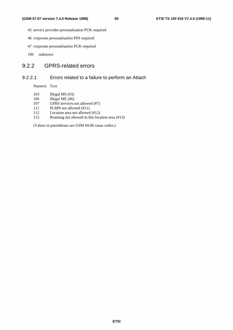
ETSI
ETSI TS 100 916 V7.4.0 (1999-11)90(GSM 07.07 version 7.4.0 Release 1998)
45 service provider personalisation PUK required
46 corporate personalisation PIN required
47 corporate personalisation PUK required
100 unknown
9.2.2 GPRS-related errors
9.2.2.1 Errors related to a failure to perform an Attach
Numeric Text
103 Illegal MS (#3)106 Illegal ME (#6)107 GPRS services not allowed (#7)111 PLMN not allowed (#11)112 Location area not allowed (#12)113 Roaming not allowed in this location area (#13)
(Values in parentheses are GSM 04.08 cause codes.)

ETSI
ETSI TS 100 916 V7.4.0 (1999-11)91(GSM 07.07 version 7.4.0 Release 1998)
9.2.2.2 Errors related to a failure to Activate a Context
Numeric Text
132 service option not supported (#32)133 requested service option not subscribed (#33)134 service option temporarily out of order (#34)149 PDP authentication failure
(Values in parentheses are GSM 04.08 cause codes.)
9.2.2.3 Other GPRS errors
Numeric Text
150 invalid mobile class
148 unspecified GPRS error
Other values in the range 101 - 150 are reserved for use by GPRS
Also all other values below 256 are reserved
ImplementationMandatory for numeric format codes applicable to implemented command set.
9.3 Informative examplesAn example of TA responses with all three +CMEE values when ME manufacturer identification is requested but ME isnot connected to the TA:
AT+CMEE=0 (+CME ERROR shall not be used)OKAT+CGMIERRORAT+CMEE=1 (use numeric <err>)OKAT+CGMI+CME ERROR: 1AT+CMEE=2 (use verbose <err>)OKAT+CGMI+CME ERROR: no connection to phone
10 Commands for GPRSThis clause defines commands that a TE may use to control a GPRS MT. Other aspects of a GPRS MT are described inGSM 07.60 [34].
It is anticipated that GPRS MTs will vary widely in functionality. At one extreme, a class A MT might support multiplePDP types as well as circuit switched data, and use multiple external networks and QoS profiles. At the other extreme aclass C MT might support only a single PDP type using a single external network, and rely on the HLR to contain thePDP context definition.
A comprehensive set of GPRS-specifc commands is defined in clause 10.1 to provide the flexibility needed by the morecomplex MT. The commands are designed to be expandable to accommodate new PDP types and interface protocols,merely by defining new values for many of the parameters. Multiple contexts may be activated if the interface link-layerprotocol is able to support them. The commands use the extended information and error message capabilities describedin this specification.
For MTs of intermediate complexity, most commands have simplified forms where certain parameters may be omitted.
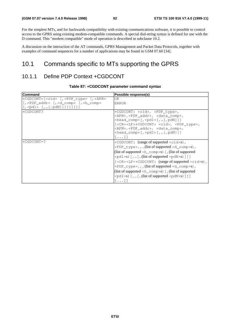
ETSI
ETSI TS 100 916 V7.4.0 (1999-11)92(GSM 07.07 version 7.4.0 Release 1998)
For the simplest MTs, and for backwards compatibility with existing communications software, it is possible to controlaccess to the GPRS using existing modem-compatible commands. A special dial-string syntax is defined for use with theD command. This "modem compatible" mode of operation is described in subclause 10.2.
A discussion on the interaction of the AT commands, GPRS Management and Packet Data Protocols, together withexamples of command sequences for a number of applications may be found in GSM 07.60 [34].
10.1 Commands specific to MTs supporting the GPRS
10.1.1 Define PDP Context +CGDCONT
Table 87: +CGDCONT parameter command syntax
Command Possible response(s)+CGDCONT=[<cid> [,<PDP_type> [,<APN>[,<PDP_addr> [,<d_comp> [,<h_comp>[,<pd1> [,…[,pdN]]]]]]]]]
OKERROR
+CGDCONT? +CGDCONT: <cid>, <PDP_type>,<APN>,<PDP_addr>, <data_comp>,<head_comp>[,<pd1>[,…[,pdN]]][<CR><LF>+CGDCONT: <cid>, <PDP_type>,<APN>,<PDP_addr>, <data_comp>,<head_comp>[,<pd1>[,…[,pdN]]][...]]
+CGDCONT=? +CGDCONT: (range of supported <cid>s),<PDP_type>,,,(list of supported <d_comp>s),(list of supported <h_comp>s)[,(list of supported<pd1>s)[,…[,(list of supported <pdN>s)]]][<CR><LF>+CGDCONT: (range of supported <cid>s),<PDP_type>,,,(list of supported <d_comp>s),(list of supported <h_comp>s)[,(list of supported<pd1>s)[,…[,(list of supported <pdN>s)]]][...]]

ETSI
ETSI TS 100 916 V7.4.0 (1999-11)93(GSM 07.07 version 7.4.0 Release 1998)
Description
The set command specifies PDP context parameter values for a PDP context identified by the (local) contextidentification parameter, <cid>. The number of PDP contexts that may be in a defined state at the same time is givenby the range returned by the test command.
A special form of the set command, +CGDCONT= <cid> causes the values for context number <cid> to becomeundefined.
The read command returns the current settings for each defined context.
The test command returns values supported as a compound value. If the MT supports several PDP types,<PDP_type>, the parameter value ranges for each <PDP_type> are returned on a separate line.
Defined values
<cid>: (PDP Context Identifier) a numeric parameter which specifies a particular PDP context definition. Theparameter is local to the TE-MT interface and is used in other PDP context-related commands. The range ofpermitted values (minimum value = 1) is returned by the test form of the command.
<PDP_type>: (Packet Data Protocol type) a string parameter which specifies the type of packet data protocol
X25 ITU-T/CCITT X.25 layer 3IP Internet Protocol (IETF STD 5)OSPIH Internet Hosted Octet Stream ProtocolPPP Point to Point Protocol (IETF STD 51)
<APN>: (Access Point Name) a string parameter which is a logical name that is used to select the GGSN or theexternal packet data network.
If the value is null or omitted, then the subscription value will be requested.
<PDP_address>: a string parameter that identifies the MT in the address space applicable to the PDP.
If the value is null or omitted, then a value may be provided by the TE during the PDP startup procedure or,failing that, a dynamic address will be requested.
The read form of the command will continue to return the null string even if an address has been allocated duringthe PDP startup procedure. The allocated address may be read using the +CGPADDR command.
<d_comp>: a numeric parameter that controls PDP data compression0 - off (default if value is omitted)1 - onOther values are reserved.
<h_comp>: a numeric parameter that controls PDP header compression0 - off (default if value is omitted)1 - onOther values are reserved.
NOTE. At present only one data compression algorithm (V.42bis) is provided in SNDCP. If and when otheralgorithms become available, a command will be provided to select one or more of these.
<pd1>, … <pdN>: zero to N string parameters whose meanings are specific to the <PDP_type>
For PDP type OSP:IHOSS the following parameters are defined:<pd1> = <host> the fully formed domain name extended hostname of the Internet host<pd2> = <port > the TCP or UDP port on the Internet host<pd3> = <protocol> the protocol to be used over IP on the Internet - "TCP" or "UDP
Implementation
Mandatory unless only a single subscribed context is supported.
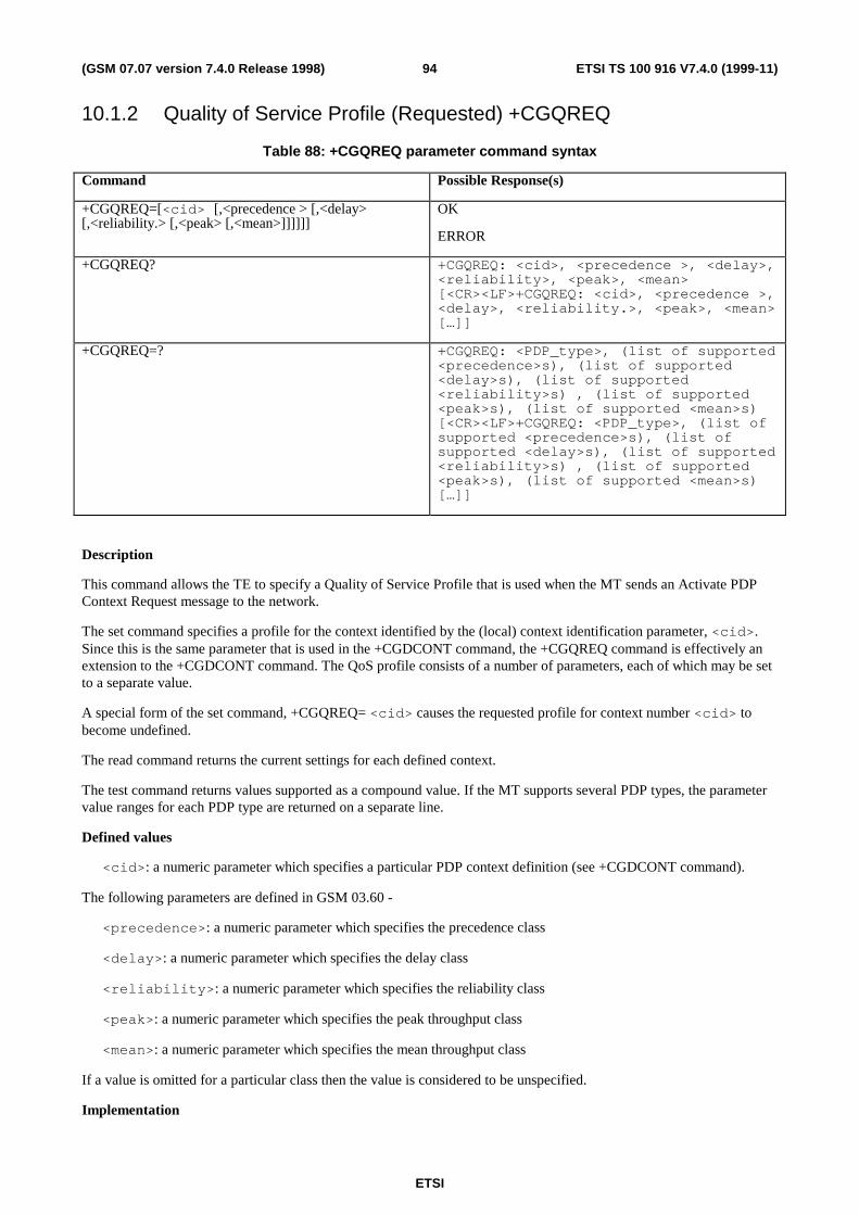
ETSI
ETSI TS 100 916 V7.4.0 (1999-11)94(GSM 07.07 version 7.4.0 Release 1998)
10.1.2 Quality of Service Profile (Requested) +CGQREQ
Table 88: +CGQREQ parameter command syntax
Command Possible Response(s)
+CGQREQ=[<cid> [,<precedence > [,<delay>[,<reliability.> [,<peak> [,<mean>]]]]]]
OK
ERROR
+CGQREQ? +CGQREQ: <cid>, <precedence >, <delay>,<reliability>, <peak>, <mean>[<CR><LF>+CGQREQ: <cid>, <precedence >,<delay>, <reliability.>, <peak>, <mean>[…]]
+CGQREQ=? +CGQREQ: <PDP_type>, (list of supported<precedence>s), (list of supported<delay>s), (list of supported<reliability>s) , (list of supported<peak>s), (list of supported <mean>s)[<CR><LF>+CGQREQ: <PDP_type>, (list ofsupported <precedence>s), (list ofsupported <delay>s), (list of supported<reliability>s) , (list of supported<peak>s), (list of supported <mean>s)[…]]
Description
This command allows the TE to specify a Quality of Service Profile that is used when the MT sends an Activate PDPContext Request message to the network.
The set command specifies a profile for the context identified by the (local) context identification parameter, <cid>.Since this is the same parameter that is used in the +CGDCONT command, the +CGQREQ command is effectively anextension to the +CGDCONT command. The QoS profile consists of a number of parameters, each of which may be setto a separate value.
A special form of the set command, +CGQREQ= <cid> causes the requested profile for context number <cid> tobecome undefined.
The read command returns the current settings for each defined context.
The test command returns values supported as a compound value. If the MT supports several PDP types, the parametervalue ranges for each PDP type are returned on a separate line.
Defined values
<cid>: a numeric parameter which specifies a particular PDP context definition (see +CGDCONT command).
The following parameters are defined in GSM 03.60 -
<precedence>: a numeric parameter which specifies the precedence class
<delay>: a numeric parameter which specifies the delay class
<reliability>: a numeric parameter which specifies the reliability class
<peak>: a numeric parameter which specifies the peak throughput class
<mean>: a numeric parameter which specifies the mean throughput class
If a value is omitted for a particular class then the value is considered to be unspecified.
Implementation

ETSI
ETSI TS 100 916 V7.4.0 (1999-11)95(GSM 07.07 version 7.4.0 Release 1998)
Optional. If the command is not implemented then all the values are considered to be unspecified.
10.1.3 Quality of Service Profile (Minimum acceptable) +CGQMIN
Table 89: +CGQMIN parameter command syntax
Command Possible Response(s)
+CGQMIN=[<cid> [,<precedence > [,<delay>[,<reliability.> [,<peak> [,<mean>]]]]]]
OK
ERROR
+CGQMIN? +CGQMIN: <cid>, <precedence >, <delay>,<reliability>, <peak>, <mean>[<CR><LF>+CGQMIN: <cid>, <precedence >,<delay>, <reliability.>, <peak>, <mean>[…]]
+CGQMIN=? +CGQMIN: <PDP_type>, (list of supported<precedence>s), (list of supported<delay>s), (list of supported<reliability>s) , (list of supported<peak>s), (list of supported <mean>s)[<CR><LF>+CGQMIN: <PDP_type>, (list ofsupported <precedence>s), (list ofsupported <delay>s), (list of supported<reliability>s) , (list of supported<peak>s), (list of supported <mean>s)[…]]
Description
This command allows the TE to specify a minimum acceptable profile which is checked by the MT against thenegotiated profile returned in the Activate PDP Context Accept message.
The set command specifies a profile for the context identified by the (local) context identification parameter, <cid>.Since this is the same parameter that is used in the +CGDCONT command, the +CGQMIN command is effectively anextension to the +CGDCONT command. The QoS profile consists of a number of parameters, each of which may be setto a separate value.
A special form of the set command, +CGQMIN= <cid> causes the minimum acceptable profile for context number<cid> to become undefined. In this case no check is made against the negotiated profile.
The read command returns the current settings for each defined context.
The test command returns values supported as a compound value. If the MT supports several PDP types, the parametervalue ranges for each PDP type are returned on a separate line.
Defined values
<cid>: a numeric parameter which specifies a particular PDP context definition (see +CGDCONT command).
The following parameters are defined in GSM 03.60 -
<precedence>: a numeric parameter which specifies the precedence class
<delay>: a numeric parameter which specifies the delay class
<reliability>: a numeric parameter which specifies the reliability class
<peak>: a numeric parameter which specifies the peak throughput class
<mean>: a numeric parameter which specifies the mean throughput class
If a value is omitted for a particular class then this class is not checked.

ETSI
ETSI TS 100 916 V7.4.0 (1999-11)96(GSM 07.07 version 7.4.0 Release 1998)
Implementation
Optional. If the command is not implemented then no check is made against the negotiated profile.
10.1.4 GPRS attach or detach +CGATT
Table 90: CGATT action command syntax
Command Possible Response(s)
+CGATT= [<state>] OKERROR
+CGATT? +CGATT: <state>
+CGATT=? +CGATT: (list of supported <state>s)
Description
The execution command is used to attach the MT to, or detach the MT from, the GPRS service. After the command hascompleted, the MT remains in V.25ter command state. If the MT is already in the requested state, the command isignored and the OK response is returned. If the requested state cannot be achieved, an ERROR or +CME ERRORresponse is returned. Extended error responses are enabled by the +CMEE command.
Any active PDP contexts will be automatically deactivated when the attachment state changes to detached.
The read command returns the current GPRS service state.
The test command is used for requesting information on the supported GPRS service states.
NOTE: This command has the characteristics of both the V.25ter action and parameter commands. Hence it hasthe read form in addition to the execution/set and test forms.
Defined Values
<state>: indicates the state of GPRS attachment0 - detached1 - attachedOther values are reserved and will result in an ERROR response to the execution command.
Implementation
Optional.
10.1.5 PDP context activate or deactivate +CGACT
Table 91: CGACT action command syntax
Command Possible Response(s)
+CGACT=[<state> [,<cid>[,<cid>[,…]]]] OKERROR
+CGACT? +CGACT: <cid>, <state>[<CR><LF>+CGACT: <cid>, <state>[...]]
+CGACT=? +CGACT: (list of supported <state>s)
Description

ETSI
ETSI TS 100 916 V7.4.0 (1999-11)97(GSM 07.07 version 7.4.0 Release 1998)
The execution command is used to activate or deactivate the specified PDP context (s). After the command hascompleted, the MT remains in V.25ter command state. If any PDP context is already in the requested state, the state forthat context remains unchanged. If the requested state for any specified context cannot be achieved, an ERROR or+CME ERROR response is returned. Extended error responses are enabled by the +CMEE command. If the MT is notGPRS attached when the activation form of the command is executed, the MT first performs a GPRS attach and themattempts to activate the specified contexts. If the attach fails then the MT responds with ERROR or, if extended errorresponses are enabled, with the appropriate failure-to-attach error message.
If no <cid>s are specified the activation form of the command activates all defined contexts.
If no <cid>s are specified the deactivation form of the command deactivates all active contexts.
The read command returns the current activation states for all the defined PDP contexts.
The test command is used for requesting information on the supported PDP context activation states.
NOTE. This command has the characteristics of both the V.25ter action and parameter commands. Hence it hasthe read form in addition to the execution/set and test forms.
Defined Values
<state>: indicates the state of PDP context activation0 - deactivated1 - activatedOther values are reserved and will result in an ERROR response to the execution command.
<cid>: a numeric parameter which specifies a particular PDP context definition (see +CGDCONTcommand).+CGDCONT
Implementation
Optional.

ETSI
ETSI TS 100 916 V7.4.0 (1999-11)98(GSM 07.07 version 7.4.0 Release 1998)
10.1.6 Enter data state +CGDATA
Table 92: +CGDATA action command syntax
Command Possible Response(s)
+CGDATA=[<L2P> ,[<cid> [,<cid> [,…]]]] CONNECTERROR
+CGDATA=? +CGDATA: (list of supported <L2P>s)
Description
The execution command causes the MT to perform whatever actions are necessary to establish communication betweenthe TE and the network using one or more GPRS PDP types. This may include performing a GPRS attach and one ormore PDP context activations. If the <L2P> parameter value is unacceptable to the MT, the MT shall return an ERRORor +CME ERROR response. Otherwise, the MT issues the intermediate result code CONNECT and enters V.25teronline data state.
Commands following +CGDATA command in the AT command line shall not be processed by the MT.
The detailed behaviour after the online data state has been entered is dependent on the PDP type. It is described brieflyin GSM 07.60 and in more detail in GSM 09.61 and the specifications for the relevant PDPs. GPRS attachment andPDP context activation procedures may take place prior to or during the PDP startup if they have not already beenperformed using the +CGATT and +CGACT commands.
If context activation takes place during the PDP startup, one or more <cid>s may be specified in order to provide theinformation needed for the context activation request(s).
During each PDP startup procedure the MT may have access to some or all of the following information -
The MT may have a priori knowledge, for example, it may implement only one PDP type.
The command may have provided an <L2P> parameter value.
The TE may provide a PDP type and/or PDP address to the MT during in the PDP startup procedure.
If any of this information is in conflict, the command will fail.
Any PDP type and/or PDP address present in the above information shall be compared with the PDP type and/or PDPaddress in any context definitions specified in the command in the order in which their <cid>s appear. For a contextdefinition to match -
The PDP type must match exactly.
The PDP addresses are considered to match if they are identical or if either or both addresses are unspecified. Forexample, a PPP NCP request specifying PDP type = IP and no PDP address would cause the MT to searchthrough the specified context definitions for one with PDP type = IP and any PDP address.
The context shall be activated using the matched value for PDP type and a static PDP address if available, together withthe other information found in the PDP context definition. If a static PDP address is not available then a dynamicaddress is requested.
If no <cid> is given or if there is no matching context definition, the MT shall attempt to activate the context withwhatever information is available to the MT. The other context parameters shall be set to their default values.
If the activation is successful, data transfer may proceed.
After data transfer is complete, and the layer 2 protocol termination procedure has completed successfully, the V.25tercommand state is re-entered and the MT returns the final result code OK.
In the event of an erroneous termination or a failure to start up, the V.25ter command state is re-entered and the MTreturns the final result code NO CARRIER or, if enabled, +CME ERROR. Attach, activate and other errors may bereported.

ETSI
ETSI TS 100 916 V7.4.0 (1999-11)99(GSM 07.07 version 7.4.0 Release 1998)
The test command is used for requesting information on the supported layer 2 protocols.
This command may be used in both normal and modem compatibility modes.
Defined Values
<L2P>: a string parameter that indicates the layer 2 protocol to be used between the TE and MTNULL none, for PDP type OSP:IHOSSPPP Point-to-point protocol for a PDP such as IPPAD character stream for X.25 character (triple X PAD) modeX25 X.25 L2 (LAPB) for X.25 packet modeM-xxxx manufacturer-specific protocol (xxxx is an alphanumeric string)
If the value is omitted, the layer 2 protocol is unspecified. Other values are reserved and will result in an ERRORresponse.
<cid>: a numeric parameter which specifies a particular PDP context definition (see +CGDCONT command).
Implementation
Optional if the D (dial) command can be used to specify GPRS operation.
10.1.7 Configure local Octet Stream PAD parameters +CGCLOSP
Table 93: CGCLOSP parameter command syntax
Command Possible Response(s)
+CGCLOSP=[<parm>, <value>] OK
ERROR
+CGCLOSP? +CGCLOSP: <parm>, <value>[<CR><LF>+CGCLOSP: <parm>, <value>>[...]]
+CGCLOSP=? +CGCLOSP: <parm>, (list of supported<value>s)[<CR><LF>+CGCLOSP: <parm>, (list ofsupported <value>s)[...]]
Description
The set command sets the value of a specified OSP PAD parameter in the local PAD. The set of parameters to besupported is listed in the OSP protocol specification.
Setting the maximum sizes for the local Packet Assembly and Disassembly buffers will cause corresponding values forthe GGSN relay buffers to be negotiated.
The read command returns, one per line, the value of each of the supported parameters.
The test command returns, one per line, the permitted range of values for each of the supported parameters.
Defined values
<parm>: a numeric parameter which specifies the PAD parameter to be configured
<value>: a numeric parameter which specifies the value to which PAD parameter is to be set
If <value> is omitted for a particular parameter then <parm> is set to the OSP-defined default, if any.
Implementation
Optional.
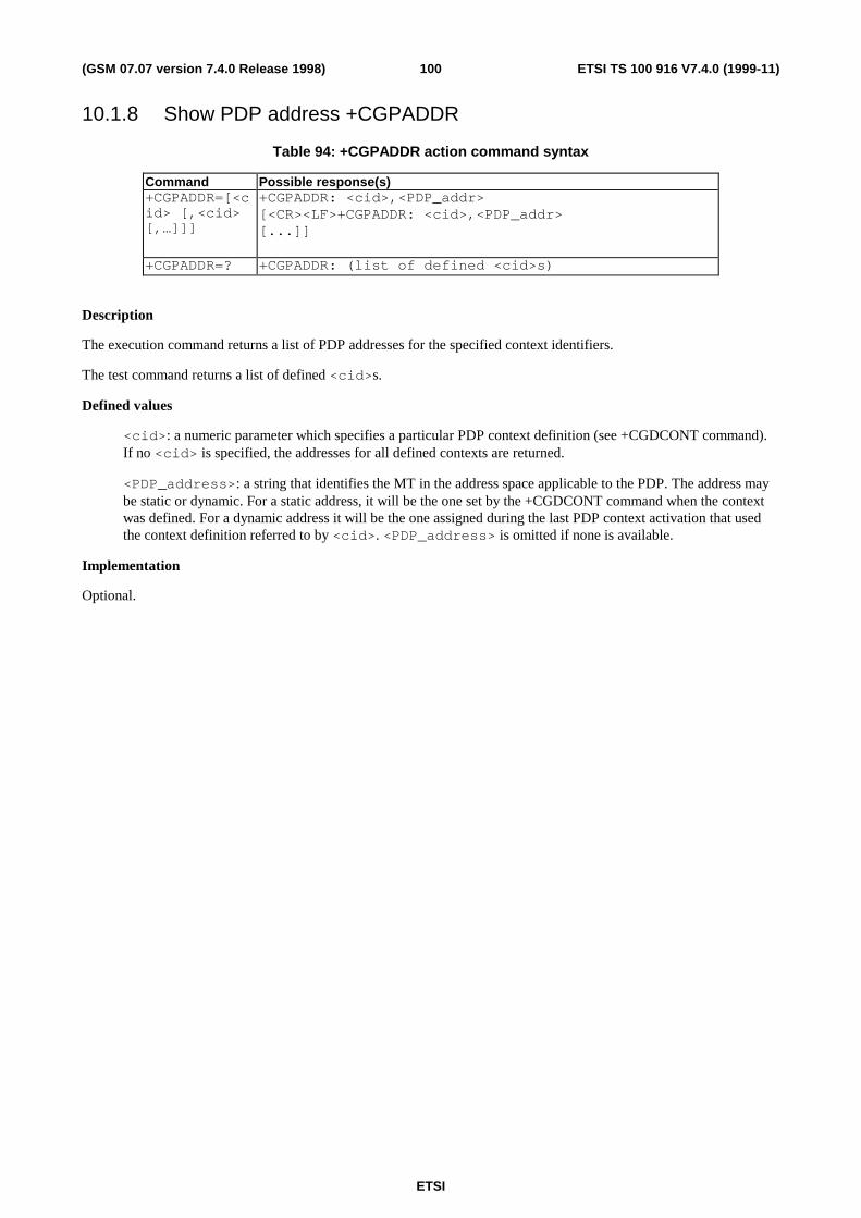
ETSI
ETSI TS 100 916 V7.4.0 (1999-11)100(GSM 07.07 version 7.4.0 Release 1998)
10.1.8 Show PDP address +CGPADDR
Table 94: +CGPADDR action command syntax
Command Possible response(s)+CGPADDR=[<cid> [,<cid>[,…]]]
+CGPADDR: <cid>,<PDP_addr>[<CR><LF>+CGPADDR: <cid>,<PDP_addr>[...]]
+CGPADDR=? +CGPADDR: (list of defined <cid>s)
Description
The execution command returns a list of PDP addresses for the specified context identifiers.
The test command returns a list of defined <cid>s.
Defined values
<cid>: a numeric parameter which specifies a particular PDP context definition (see +CGDCONT command).If no <cid> is specified, the addresses for all defined contexts are returned.
<PDP_address>: a string that identifies the MT in the address space applicable to the PDP. The address maybe static or dynamic. For a static address, it will be the one set by the +CGDCONT command when the contextwas defined. For a dynamic address it will be the one assigned during the last PDP context activation that usedthe context definition referred to by <cid>. <PDP_address> is omitted if none is available.
Implementation
Optional.

ETSI
ETSI TS 100 916 V7.4.0 (1999-11)101(GSM 07.07 version 7.4.0 Release 1998)
10.1.9 Automatic response to a network request for PDP context activation+CGAUTO
Table 95: CGAUTO parameter command syntax
Command Possible response(s)+CGAUTO=[<n>] OK
ERROR+CGAUTO? +CGAUTO: <n>+CGAUTO=? +CGAUTO: (list of supported <n>s)
Description
The set command disables or enables an automatic positive response (auto-answer) to the receipt of a Request PDPContext Activation message from the network. It also provides control over the use of the V.25ter basic commands 'S0','A and 'H' for handling network requests for PDP context activation. The setting does not affect the issuing of theunsolicited result code RING or +CRING.
The test command returns the values of <n> supported by the MT as a compound value.
When the +CGAUTO=0 command is received, the MT shall not perform a GPRS detach if it is attached. Subsequently,when the MT announces a network request for PDP context activation by issuing the unsolicited result code RING or+CRING, the TE may manually accept or reject the request by issuing the +CGANS command or may simply ignore thenetwork request.
When the +CGAUTO=1 command is received, the MT shall attempt to perform a GPRS attach if it is not alreadyattached. Failure will result in ERROR or, if enabled, +CME ERROR being returned to the TE. Subsequently, when theMT announces a network request for PDP context activation by issuing the unsolicited result code RING or +CRING tothe TE, this is followed by the intermediate result code CONNECT. The MT then enters V.25ter online data state andfollows the same procedure as it would after having received a +CGANS=1 with no <L2P> or <cid> values specified.
Defined values
<n>:
0 turn off automatic response for GPRS only1 turn on automatic response for GPRS only2 modem compatibility mode, GPRS only3 modem compatibility mode, GPRS and circuit switched calls (default)
For <n> = 0 GPRS network requests are manually accepted or rejected by the +CGANS command.
For <n> = 1 GPRS network requests are automatically accepted according to the description above.
For <n> = 2, automatic acceptance of GPRS network requests is controlled by the 'S0' command. Manual control usesthe 'A' and 'H' commands, respectively, to accept and reject GPRS requests. (+CGANS may also be used.) Incomingcircuit switched calls can be neither manually nor automatically answered.
For <n> = 3, automatic acceptance of both GPRS network requests and incoming circuit switched calls is controlled bythe 'S0' command. Manual control uses the 'A' and 'H' commands, respectively, to accept and reject GPRS requests.(+CGANS may also be used.) Circuit switched calls are handled as described elsewhere in this specification.
Implementation
Optional. If not implemented, the MT shall behave according to the case of <n> = 3.

ETSI
ETSI TS 100 916 V7.4.0 (1999-11)102(GSM 07.07 version 7.4.0 Release 1998)
10.1.10 Manual response to a network request for PDP context activation+CGANS
Table 96: CGANS action command syntax
Command Possible response(s)+CGANS=[<response>,[<L2P> ,[<cid>]]]
OKERROR
+CGANS=? +CGANS: (list of supported<response>s), (list of supported<L2P>s)
Description
The execution command requests the MT to respond to a network request for GPRS PDP context activation which hasbeen signalled to the TE by the RING or +CRING: unsolicited result code. The <response> parameter allows the TEto accept or reject the request.
If <response> is 0, the request is rejected and the MT returns OK to the TE.
If <response> is 1, the following procedure is followed by the MT.
Commands following the +CGANS command in the AT command line shall not be processed by the MT.
If the <L2P> parameter value is unacceptable to the MT, the MT shall return an ERROR or +CME ERROR response.Otherwise, the MT issues the intermediate result code CONNECT and enters V.25ter online data state.
The detailed behaviour after the online data state has been entered is dependent on the PDP type. It is described brieflyin GSM 07.60 and in more detail in GSM 09.61 and the specifications for the relevant PDPs. PDP context activationprocedures shall take place prior to or during the PDP startup.
One or more <cid>s may be specified in order to provide the values needed for the context activation request.
During the PDP startup procedure the MT has the PDP type and the PDP address provided by the network in theRequest PDP Context Activation message. The MT may also have some or all of the following information -
The MT may have a priori knowledge, for example, it may implement only one PDP type.
The command may have provided an <L2P> parameter value.
The TE may provide one or both of PDP type and PDP address to the MT in the PDP startup.
If any of this information is in conflict, the command will fail.
If one or more <cid> is given then an attempt shall be made to identify an appropriate context definition by matching thePDP type and PDP address in the network request with the PDP type and PDP address in each of the specified contextdefinitions (in the order in which their <cid>s appear in the command) as follows -
The PDP type must match exactly.
The PDP addresses are considered to match if they are identical or if the address in the context definition isunspecified.
The context shall be activated using the values for PDP type and PDP address provided by the network, together withthe other information found in the PDP context definition. An APN may or may not re required, depending on theapplication.
If no <cid> is given or if there is no matching context definition, the MT will attempt to activate the context using thevalues for PDP type and PDP address provided by the network, together with any other relevant information known tothe MT. The other context parameters will be set to their default values.
If the activation is successful, data transfer may proceed.

ETSI
ETSI TS 100 916 V7.4.0 (1999-11)103(GSM 07.07 version 7.4.0 Release 1998)
After data transfer is complete, and the layer 2 protocol termination procedure has completed successfully, the V.25tercommand state is re-entered and the MT returns the final result code OK
In the event of an erroneous termination or a failure to startup, the V.25ter command state is re-entered and the MTreturns the final result code NO CARRIER or, if enabled, +CME ERROR. Attach, activate and other errors may bereported. It is also an error to issue the +CGANS command when there is no outstanding network request.
NOTE: This is not the same as if the MT issues a +CGDATA (or +CGACT) command after receiving a +CRINGunsolicited result code. A +CGDATA (or +CGACT) does not command the MT to acknowledge thenetwork request but rather to make a new request for context activation. The network request would beignored.
The test command returns the values of <response> and <L2P> supported by the MT as compound values.
This command may be used in both normal and modem compatibility modes.
Defined values
<response>: is a numeric parameter which specifies how the request should be responded to.
0 reject the request1 accept and request that the PDP context be activated
If <response> is omitted it is assumed to be 0. Other values are reserved and will result in the ERROR response.
<L2P>: a string parameter which indicates the layer 2 protocol to be used (see +CGDATA command).
<cid>: a numeric parameter which specifies a particular PDP context definition (see +CGDCONT command).
Implementation
Optional.
10.1.11 GPRS mobile station class +CGCLASS
Table 97: CGCLASS parameter command syntax
Command Possible Response(s)
+CGCLASS= [<class>] OKERROR
+CGCLASS? +CGCLASS: <class>
+CGCLASS=? +CGCLASS: (list of supported <class>s)
Description
The set command is used to set the MT to operate according to the specified GPRS mobile class. If the requested class isnot supported, an ERROR or +CME ERROR response is returned. Extended error responses are enabled by the +CMEEcommand.
The read command returns the current GPRS mobile class.
The test command is used for requesting information on the supported GPRS mobile classes.

ETSI
ETSI TS 100 916 V7.4.0 (1999-11)104(GSM 07.07 version 7.4.0 Release 1998)
Defined Values
<class>: a string parameter which indicates the GPRS mobile class (in descending order of functionality)A class A (highest)B class BC class C in GPRS and circuit switched alternate modeCG class C in GPRS only modeCC class C in circuit switched only mode (lowest)
Other values are reserved and will result in an ERROR response to the set command.
If the MT is GPRS attached when the set command is issued with a <class> = CC specified, a detach request shall besent to the network.
Implementation
Optional.
10.1.12 Configure local triple-X PAD parameters +CGCLPAD
Table 98: CGCLPAD parameter command syntax
Command Possible Response(s)
+CGCLPAD=[<parm>, <value>] OK
ERROR
+CGCLPAD? +CGCLPAD: <parm>, <value>[<CR><LF>+CGCLPAD: <parm>, <value>>[…]]
+CGCLPAD=? +CGCLPAD: <parm>, (list of supported<value>s)[<CR><LF>+CGCLPAD: <parm>, (list ofsupported <value>s)[…]]
Description
The set command sets the value of a specified X.3 PAD parameter in the local PAD. A minimum set of parameters to besupported is listed in GSM 07.60.
The read command returns, one per line, the value of each of the supported parameters.
The test command returns, one per line, the permitted range of values for each of the supported parameters.
Defined values
<parm>: a numeric parameter which specifies the X.3 parameter to be configured
<value>: a numeric parameter which specifies the value to which the X.3 parameter is to be set
If <value> is omitted for a particular class then <parm> is set to the X.3-defined default, if any.
Implementation
Optional.

ETSI
ETSI TS 100 916 V7.4.0 (1999-11)105(GSM 07.07 version 7.4.0 Release 1998)
10.1.13 GPRS event reporting +CGEREP
Table 99: CGEREP parameter command syntax
Command Possible response(s)+CGEREP=[<mode>[,<bfr>]] OK
ERROR+CGEREP? +CGEREP: <mode>,<bfr>+CGEREP=? +CGEREP: (list of supported <mode>s),(list of supported
<bfr>s)
Description
Set command enables or disables sending of unsolicited result codes, +CGEV: XXX from MT to TE in the case ofcertain events occurring in the GPRS MT or the network. <mode> controls the processing of unsolicited result codesspecified within this command. <bfr> controls the effect on buffered codes when <mode> 1 or 2 is entered. If asetting is not supported by the MT, ERROR or +CME ERROR: is returned.
Read command returns the current mode and buffer settings
Test command returns the modes and buffer settings supported by the MT as compound values.
Defined values
<mode>:
0 buffer unsolicited result codes in the MT; if MT result code buffer is full, the oldest ones can be discarded. Nocodes are forwarded to the TE.
1 discard unsolicited result codes when MT-TE link is reserved (e.g. in on-line data mode); otherwise forward themdirectly to the TE
2 buffer unsolicited result codes in the MT when MT-TE link is reserved (e.g. in on-line data mode) and flush themto the TE when MT-TE link becomes available; otherwise forward them directly to the TE
<bfr>:
0 MT buffer of unsolicited result codes defined within this command is cleared when <mode> 1 or 2 is entered
1 MT buffer of unsolicited result codes defined within this command is flushed to the TE when <mode> 1 or 2 isentered (OK response shall be given before flushing the codes)
Defined events
The following unsolicited result codes and the corresponding events are defined -
+CGEV: REJECT <PDP_type>, <PDP_addr>
A network request for PDP context activation occurred when the MT was unable to report it to the TE with a+CRING unsolicited result code and was automatically rejected.
+CGEV: NW REACT <PDP_type>, <PDP_addr>, [<cid>]
The network has requested a context reactivation. The <cid> that was used to reactivate the context is providedif known to the MT.
+CGEV: NW DEACT <PDP_type>, <PDP_addr>, [<cid>]
The network has forced a context deactivation. The <cid> that was used to activate the context is provided ifknown to the MT.

ETSI
ETSI TS 100 916 V7.4.0 (1999-11)106(GSM 07.07 version 7.4.0 Release 1998)
+CGEV: ME DEACT <PDP_type>, <PDP_addr>, [<cid>]
The mobile equipment has forced a context deactivation. The <cid> that was used to activate the context isprovided if known to the MT.
+CGEV: NW DETACH
The network has forced a GPRS detach. This implies that all active contexts have been deactivated. These are notreported separately.
+CGEV: ME DETACH
The mobile equipment has forced a GPRS detach. This implies that all active contexts have been deactivated.These are not reported separately.
+CGEV: NW CLASS <class>
The network has forced a change of MS class. The highest available class is reported (see +CGCLASS).
+CGEV: ME CLASS <class>
The mobile equipment has forced a change of MS class. The highest available class is reported (see+CGCLASS).
Implementation
Optional.
10.1.14 GPRS network registration status +CGREG
Table 100: CGREG parameter command syntax
Command Possible response(s)+CGREG=[<n>]+CGREG? +CGREG: <n>,<stat>[,<lac>,<ci>]
+CME ERROR: <err>+CGREG=? +CGREG: (list of supported <n>s)
Description
The set command controls the presentation of an unsolicited result code +CGREG: <stat> when <n>=1 and there isa change in the MT's GPRS network registration status, or code +CGREG: <stat>[,<lac>,<ci>] when <n>=2and there is a change of the network cell.
NOTE. If the GPRS MT also supports circuit mode services, the +CREG command and +CREG: result codeapply to the registration status and location information for those services.
The read command returns the status of result code presentation and an integer <stat> which shows whether thenetwork has currently indicated the registration of the MT. Location information elements <lac> and <ci> arereturned only when <n>=2 and MT is registered in the network.

ETSI
ETSI TS 100 916 V7.4.0 (1999-11)107(GSM 07.07 version 7.4.0 Release 1998)
Defined values
<n>:
0 disable network registration unsolicited result code
1 enable network registration unsolicited result code +CGREG: <stat>
2 enable network registration and location information unsolicited result code +CGREG:<stat>[,<lac>,<ci>]
<stat>:
0 not registered, ME is not currently searching a new operator to register to
1 registered, home network
2 not registered, but ME is currently searching a new operator to register to
3 registration denied
4 unknown
5 registered, roaming
<lac>: string type; two byte location area code in hexadecimal format (e.g. "00C3" equals 195 in decimal)
<ci>: string type; two byte cell ID in hexadecimal format
Implementation
Optional.
10.1.15 Select service for MO SMS messages +CGSMS
Table 101: CGSMS parameter command syntax
Command Possible Response(s)
+CGSMS= [<service>] OKERROR
+CGSMS? +CGSMS: <service>
+CGSMS=? +CGSMS: (list of currently available <service>s)
Description
The set command is used to specify the service or service preference that the MT will use to send MO SMS messages.
The read command returns the currently selected service or service preference.
The test command is used for requesting information on the currently available services and service preferences.
Defined Values
<service>: a numeric parameter which indicates the service or service preference to be used0 GPRS1 circuit switched2 GPRS preferred (use circuit switched if GPRS not available)3 circuit switched preferred (use GPRS if circuit switched not available)

ETSI
ETSI TS 100 916 V7.4.0 (1999-11)108(GSM 07.07 version 7.4.0 Release 1998)
Other values are reserved and will result in an ERROR response to the set command.
Implementation
Optional.
10.2 Modem compatibility commandsThis subclause describes how existing AT commands, designed for use with a modem, may be used to control a GPRSMT. This is to provide backwards compatibility with existing communications software. For new applications it isrecommended that the GPRS-specific commands, described in previous subclauses, be used.
10.2.1 MT originated PDP context activation
In this mode of operation, the MT behaves like an originating modem and accepts the normal V.25ter commandsassociated with placing and clearing a call. If GPRS-specific configuration commands are required, they may be sent tothe MT as part of the modem initialisation commands.
10.2.1.1 Request GPRS service 'D'
Table 102: D command syntax
Command Possible Response(s)
D*<GPRS_SC>[*[<called_address>][*[<L2P>][*[<cid>]]]]#
CONNECTERROR
Description
This command causes the MT to perform whatever actions are necessary to establish communication between the TEand the external PDN.
The V.25ter 'D' (Dial) command causes the MT to enter the V.25ter online data state and, with the TE, to start thespecified layer 2 protocol. The MT shall return CONNECT to confirm acceptance of the command prior to entering theV.25ter online data state. No further commands may follow on the AT command line.
The detailed behaviour after the online data state has been entered is dependent on the PDP type. It is described brieflyin clauses 8 (for X.25) and 9 (for IP) of GSM 07.60. GPRS attachment and PDP context activation procedures may takeplace prior to or during the PDP startup if they have not already been performed using the +CGATT and +CGACTcommands.
When the layer 2 protocol has terminated, either as a result of an orderly shut down of the PDP or an error, the MT shallenter V.25ter command state and return the NO CARRIER final result code.
If <called address> is supported and provided, the MT shall automatically set up a virtual call to the specifiedaddress after the PDP context has been activated.
If <L2P> and <cid> are supported, their usage shall be the same as in the +CGDATA command. The +CGDCONT,+CGQREQ, etc. commands may then be used in the modem initialisation AT command string to set values for for PDPtype, APN, QoS etc..
If <L2P> is not supported or is supported but omitted, the MT shall use a layer 2 protocol appropriate to the PDP type.
If <cid> is not supported or is supported but omitted, the MT shall attempt to activate the context using:
(a) any information provided by the TE during the PDP startup procedure, e.g. the TE may provide a PDP typeand/or PDP address to the MT,
or, (b) a priori knowledge, e.g. the MT may implement only one PDP type,

ETSI
ETSI TS 100 916 V7.4.0 (1999-11)109(GSM 07.07 version 7.4.0 Release 1998)
or, (c) using the 'Empty PDP type' (GSM 04.08). (No PDP address or APN shall be sent in this case and only onePDP context subscription record shall be present in the HLR for this subscriber.)
This command may be used in both normal and modem compatibility modes.
NOTE. The dial string conforms to the syntax specified in GSM 02.30.
Defined Values
<GPRS_SC>: (GPRS Service Code) a digit string (value 99) which identifies a request to use the GPRS
<called_address>: a string that identifies thecalled party in the address space applicable to the PDP. Forcommunications software that does not support arbitrary characters in the dial string, a numeric equivalent maybe used. Also, the character comma ',' may be used as a substitute for the character period '.'.For PDP type OSP:IHOSS, the following syntax may be used for <called_address>:
[<host>][@[<port>][@[<protocol>]]]where <host>, <port> and <protocol> are defined in the +CGDCONT description. For communications softwarethat does not support arbitrary characters in the dial string, a numeric equivalent to the hostname may be used.However, this should be avoided if at all possible.
<L2P>: a string which indicates the layer 2 protocol to be used (see +CGDATA command). For communicationssoftware that does not support arbitrary characters in the dial string, the following numeric equivalents shall beused:0 NULL1 PPP2 PAD3 X259yyyy M-xxxxOther values are reserved and will result in an ERROR response to the set command.
NOTE. V.250 (and certain communications software) does not permit arbitrary characters in the dial string. The<L2P> and <called_address> strings are therefore specified as containing digits (0-9) only.
<cid>: a digit string which specifies a particular PDP context definition (see +CGDCONT command).
Implementation
Optional if the +CGDATA command is supported. If the D command is provided, then support for<called_address>, <L2P> and <cid> are optional. If they are not supported but values are provided by the TE,the values shall be ignored and this shall not constitute an error.
10.2.2 Network requested PDP context activation
In this mode of operation, the MT behaves like an answering modem and accepts the normal V.25ter commandsassociated with answering a call. If GPRS-specific configuration commands are required, they may be sent to the MT aspart of the modem initialisation commands.
The +CGAUTO command is used to select modem compatibility mode.
10.2.2.1 Automatic response to a network request for PDP context activation 'S0'
The V.25ter 'S0=n' (Automatic answer) command may be used to turn off (n=0) and on (n>0) the automatic response toa network request for a PDP context activation.
When the 'S0=n' (n>0) command is received, the MT shall attempt to perform a GPRS attach if it is not alreadyattached. Failure will result in ERROR being returned to the TE. Subsequently, the MT will announce a networkrequest for PDP context activation by issuing the unsolicited result code RING to the TE, followed by the intermediateresult code CONNECT. The MT then enters V.25ter online data state and follows the same procedure as it would afterhaving received a +CGANS=1 with no <L2P> or <cid> values specified.
NOTE. The 'S0=n' (n=0) command does not perform an automatic GPRS detach.
Implementation

ETSI
ETSI TS 100 916 V7.4.0 (1999-11)110(GSM 07.07 version 7.4.0 Release 1998)
Optional.
10.2.2.2 Manual acceptance of a network request for PDP context activation 'A'
The V.25ter 'A' (Answer) command may be used to accept a network request for a PDP context activation announced bythe unsolicited result code RING. The MT responds with CONNECT, enters V.25ter online data state and follows thesame procedure as it would after having received a +CGANS=1 with no <L2P> or <cid> values specified. It is an errorto issue the 'A' command when there is no outstanding network request.
Implementation
Optional.
10.2.2.3 Manual rejection of a network request for PDP context activation 'H'
The V.25ter 'H' or 'H0' (On-hook) command may be used to reject a network request for PDP context activationannounced by the unsolicited result code RING. The MT responds with OK. It is an error to issue the 'H' commandwhen there is no outstanding network request.
NOTE: This is an extension to the usage of the 'H' command that is described in ITU-T V.25ter.
Implementation
Optional.

ETSI
ETSI TS 100 916 V7.4.0 (1999-11)111(GSM 07.07 version 7.4.0 Release 1998)
Annex A (normative):Summary of commands from other standardsSummary of ITU-T Recommendation V.25ter [14] commands applicable to GSM:
Table A.1: V.25ter commands applicable to GSM
Name V.25tersection
Description Subclauses in thisTS
&C 6.2.8 Circuit 109 (Received line signal detector) Behaviour 4.3.&D 6.2.9 Circuit 108 (Data terminal ready) Behaviour 4.3.&F 6.1.2 Set to Factory-defined Configuration 5.8./ 3.+DR 6.6.2 Data Compression Reporting 6.20.+DS 6.6.1 Data Compression 6.20.+GCAP 6.1.9 Request Complete Capabilities List 5.8.+GCI 6.1.10 Country of Installation 5.8.+GMI 6.14 Request Manufacturer Identification 5.8./ 5.1.+GMM 6.1.5 Request Model Identification 5.8./ 5.2.+GMR 6.1.6 Request Revision Identification 5.8./ 5.3.+GOI 6.1.8 Request Global Object Identification 5.8.+GSN 6.1.7 Request Product Serial Number Identification 5.8./ 5.4.+ICF 6.2.11 DTE-DCE Character Framing 4.3.+IFC 6.2.12 DTE-DCE Local Flow Control 4.3.+ILRR 6.2.13 DTE-DCE Local Rate Reporting 4.3.+IPR 6.2.10 Fixed DTE Rate 4.3.A 6.3.5 Answer 6.19./ 6.6.D 6.3.1 Dial 6.1.-6.4./ 6.6.E 6.2.4 Command Echo 4.3.H 6.3.6 Hook Control 6.19./ 6.5./ 6.6.I 6.1.3 Request Identification Information 5.8.L 6.3.13 Monitor Speaker Loudness 6.19.M 6.3.14 Monitor Speaker Mode 6.19.O 6.3.7 Return to Online Data State 6.19.P 6.3.3 Select Pulse Dialling 6.19.Q 6.2.5 Result Code Suppression 4.3.S0 6.3.8 Automatic Answer 6.19.S10 6.3.12 Automatic Disconnect Delay 6.19.S3 6.2.1 Command Line Termination Character 4.3.S4 6.2.2 Response Formatting Character 4.3.S5 6.2.3 Command Line Editing Character 4.3.S6 6.3.9 Pause Before Blind Dialling 6.19.S7 6.3.10 Connection Completion Timeout 6.19.S8 6.3.11 Comma Dial Modifier Time 6.19.T 6.3.2 Select Tone Dialling 6.19.V 6.2.6 DCE Response Format 4.3./ 3./ 4.1./ 4.2.X 6.2.7 Result Code Selection and Call Progress Monitoring Control 4.3.Z 6.1.1 Reset To Default Configuration 5.8.
The use of ITU-T Recommendation V.42 error control protocol is not specified for GSM, but if a manufacturer choosesto implement it over transparent data service, +E prefixed commands of V.25ter [14] shall be used.
ITU-T T.31 [11] and T.32 [12] may be used as facsimile TA-TE protocols without deletions or additions to thecommand set.

ETSI
ETSI TS 100 916 V7.4.0 (1999-11)112(GSM 07.07 version 7.4.0 Release 1998)
TIA IS-99 [15] commands referenced in this TS:
Table A.2: TIA IS-99 commands in this TS
Command IS-99section
Description Subclause inthis TS
+CBC 5.6.5 Battery Charge 8.4.+CGMI 5.6.10 Request Manufacturer Identification 5.1.+CGMM 5.6.10 Request Model Identification 5.2.+CGMR 5.6.10 Request Revision Identification 5.3.+CGSN 5.6.10 Request Product Serial Number Identification 5.4.+CRC 5.6.7 Cellular Result Codes 6.11.
TIA IS-135 [16] commands referenced in this TS:
Table A.3: TIA IS-135 commands in this TS
Command IS-135section
Description Subclause inthis TS
+CBC 4.1.24 Battery Charge 8.4.+CRC 4.1.29 Cellular Result Codes 6.11.+CSQ 4.1.31 Signal Quality 8.5.
PCCA STD-101[17] commands referenced in this TS:
Table A.4: PCCA STD-101 commands in this TS
Command STD-101section
Description Subclause inthis TS
+WS46 5.2.4.6 WDS-side Stack Selection 5.9.

ETSI
ETSI TS 100 916 V7.4.0 (1999-11)113(GSM 07.07 version 7.4.0 Release 1998)
Annex B (normative):Summary of result codesV.25ter [14] result codes which can be used in GSM and codes defined in this TS:
Table B.1: Result codes
Verbose result code(V.25ter command V1 set)
Numeric(V0 set)
Type Description
+CCCM: <ccm> as verbose unsolicited refer subclause 7.15 $(AT R97)$+CCWA: <number>,<type>,<class>[,<alpha>]
as verbose unsolicited refer subclause 7.11
+CCWV as verbose unsolicited refer subclause 8.28+CDEV: <elem>,<text> as verbose unsolicited refer subclause 8.10+CIEV: <ind>,<value> as verbose unsolicited refer subclause 8.10+CKEV: <key>,<press> as verbose unsolicited refer subclause 8.10+CLAV: <code> as verbose unsolicited refer subclause 8.+CLIP: <number>,<type>[,<subaddr>,<satype>[,<alpha>]]
as verbose unsolicited refer subclause 7.6
+CME ERROR: <err> as verbose final refer subclause 9.2+COLP: <number>,<type>[,<subaddr>,<satype>[,<alpha>]]
as verbose intermediate refer subclause 7.8
+CR: <type> as verbose intermediate refer subclause 6.8+CREG: <stat>[,<lac>,<ci>]
as verbose unsolicited refer subclause 7.2
+CRING: <type> as verbose unsolicited refer subclause 6.11+CSSI: <code1>[,<index>]
as verbose intermediate refer subclause 7.16
+CSSU: <code2>[,<index>[,<number>,<type>[,<subaddr>,<satype>]]]
as verbose unsolicited refer subclause 7.16
+CUSD: <m>[,<str>,<dcs>] as verbose unsolicited refer subclause 7.14+DR: <type> as verbose intermediate refer subclause 6.13+ILRR: <rate> as verbose intermediate refer subclause 4.3BUSY 6 final busy signal detectedCONNECT 1 intermediate connection has been establishedCONNECT <text> manufacturer
specificintermediate as CONNECT but manufacturer specific
<text> gives additional information (e.g.connection data rate)
ERROR 4 final command not acceptedNO ANSWER 7 final connection completion timeoutNO CARRIER 3 final connection terminatedNO DIALTONE 5 final no dialtone detectedOK 0 final acknowledges execution of a command lineRING 2 unsolicited incoming call signal from network
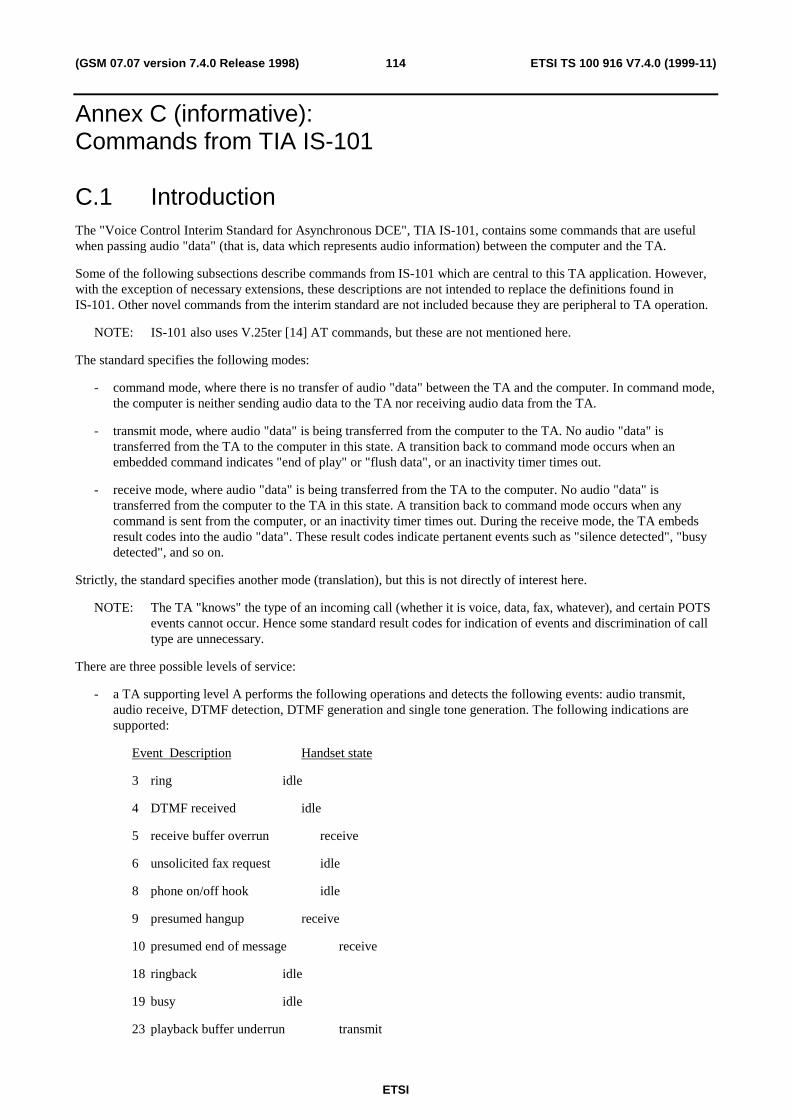
ETSI
ETSI TS 100 916 V7.4.0 (1999-11)114(GSM 07.07 version 7.4.0 Release 1998)
Annex C (informative):Commands from TIA IS-101
C.1 IntroductionThe "Voice Control Interim Standard for Asynchronous DCE", TIA IS-101, contains some commands that are usefulwhen passing audio "data" (that is, data which represents audio information) between the computer and the TA.
Some of the following subsections describe commands from IS-101 which are central to this TA application. However,with the exception of necessary extensions, these descriptions are not intended to replace the definitions found inIS-101. Other novel commands from the interim standard are not included because they are peripheral to TA operation.
NOTE: IS-101 also uses V.25ter [14] AT commands, but these are not mentioned here.
The standard specifies the following modes:
- command mode, where there is no transfer of audio "data" between the TA and the computer. In command mode,the computer is neither sending audio data to the TA nor receiving audio data from the TA.
- transmit mode, where audio "data" is being transferred from the computer to the TA. No audio "data" istransferred from the TA to the computer in this state. A transition back to command mode occurs when anembedded command indicates "end of play" or "flush data", or an inactivity timer times out.
- receive mode, where audio "data" is being transferred from the TA to the computer. No audio "data" istransferred from the computer to the TA in this state. A transition back to command mode occurs when anycommand is sent from the computer, or an inactivity timer times out. During the receive mode, the TA embedsresult codes into the audio "data". These result codes indicate pertanent events such as "silence detected", "busydetected", and so on.
Strictly, the standard specifies another mode (translation), but this is not directly of interest here.
NOTE: The TA "knows" the type of an incoming call (whether it is voice, data, fax, whatever), and certain POTSevents cannot occur. Hence some standard result codes for indication of events and discrimination of calltype are unnecessary.
There are three possible levels of service:
- a TA supporting level A performs the following operations and detects the following events: audio transmit,audio receive, DTMF detection, DTMF generation and single tone generation. The following indications aresupported:
Event Description Handset state
3 ring idle
4 DTMF received idle
5 receive buffer overrun receive
6 unsolicited fax request idle
8 phone on/off hook idle
9 presumed hangup receive
10 presumed end of message receive
18 ringback idle
19 busy idle
23 playback buffer underrun transmit

ETSI
ETSI TS 100 916 V7.4.0 (1999-11)115(GSM 07.07 version 7.4.0 Release 1998)
25 fax or data request acknowledged idle
- a TA supporting level B performs the operations and events of level A, and also supports DTMF detection whilein the transmit state.
- a TA supporting level C performs the operations and events of level B, and also supports double DTMF tonegeneration.
Since DTMF detection and generation cannot be guaranteed over current digital networks, it follows that none of thethree levels of service can be supported.
C.2 Commands
C.2.1 Select mode +FCLASSThis command puts the TA into a particular mode of operation (data, fax, voice etc.). This causes the TA to processinformation in a manner suitable for that type of information (rather than for other types of information). The values andmeanings of parameter <n> are specified in the following table.
<n> Mode
0 data
1 fax class 1 (TIA-578-A)
1.0 fax class 1 (ITU-T T.31 [11])
2 fax (manufacturer specific)
2.0 fax class 2 (ITU-T T.32 [12] and TIA-592)
3...7 reserved for other fax modes
8 voice
9...15 reserved for other voice modes
16..79 reserved
80 VoiceView (Radish)
81..255 reserved
Table C.1: +FCLASS
Command Return+FCLASS=<n>+FCLASS? <n>+FCLASS=? (list of supported <n>s)
Voice mode is of particular interest here, and has an additional result code +VCON. Specifically, +VCON indicates thatthe TA is entering the voice command mode and there is a voice connection to at least one audio input or output. Thispresupposes that some mechanism has previously initiated a connection to that audio I/O.
C.2.2 Buffer threshold setting +VBTThis refers to integers <lo> and <hi> that indicate levels within the TA transmit buffer at which flow control isasserted and deasserted. The buffer is used for averaging out the irregular timing of data from the computer, so that thedata becomes synchronous and may be sent to some audio device.

ETSI
ETSI TS 100 916 V7.4.0 (1999-11)116(GSM 07.07 version 7.4.0 Release 1998)
Table C.2: +VBT
Command Return+VBT=<lo>,<hi>+VBT? <lo>,<hi>+VBT=? (list of supported <lo>s),(list of supported <hi>s),(buffer size)
C.2.3 Calling number ID presentation +VCIDThe command refers to an integer that allows a called party to enable or disable (<n>=0) the reporting of the ID ofcalling parties, and specifies the method of presentation of the ID. This is basically the same as GSM supplementaryservice CLIP (Calling Line Identification Presentation). The presentation may be either formatted (<n>=1) orunformatted (<n>=2):
- Formatted presentation : data items are reported in the form of <tag>=<value> pairs.
<tag> <value>
DATE MMDD (month, day)
TIME HHMM (hour, minute)
NMBR calling number or P or O (P = number is private, O = number is unavailable)
NAME subscription listing name
MESG data from other (unknown) tags
- Unformatted presentation : here the data is presented in ASCII hex as printable numbers.
Table C.3: +VCID
Command Return+VCID=<n>+VCID? <n>+VCID=? (0-2)
C.2.4 Receive gain selection +VGRThis refers to the amplification by the TA of audio samples sent from the TA to the computer. The command operateson an integer <n>, range 0...255. Values larger than 128 indicate a larger gain than nominal. Values less than 128indicate a smaller gain than nominal. The entire range of 0...255 does not have to be provided. A value of zero impliesthe use of automatic gain control by the TA.
Table C.4: +VGR
Command Return+VGR=<n>+VGR? <n>+VGR=? (list of supported <n>s)
C.2.5 Transmit gain selection +VGTThis refers to the amplification by the TA of audio samples sent from the computer to the TA. The command operateson an integer <n>, range 0...255. Values larger than 128 indicate a larger gain than nominal. Values less than 128indicate a smaller gain than nominal. The entire range of 0...255 does not have to be provided. A value of zero impliesthe uses of automatic gain control by the TA.

ETSI
ETSI TS 100 916 V7.4.0 (1999-11)117(GSM 07.07 version 7.4.0 Release 1998)
Table C.5: +VGT
Command Return+VGT=<n>+VGT? <n>+VGT=? (list of supported <n>s)
C.2.6 Initialise voice parameters +VIPThis recalls manufacturer determined settings <n> of voice parameters. The command is write only. The effect of thecommand is manufacturer specific.
Table C.6: +VIP
Command Return+VIP=<n>+VIP=? (list of supported <n>s)
C.2.7 Inactivity timer +VITThis refers to the value of the inactivity timer in the TA. It is used to monitor activity on the connection between thecomputer and the TA when the computer is in "transmit" mode and sending audio data to the TA. When the connectionhas been inactive for the time set by this command, the TA leaves "transmit" mode and reverts to command mode. Aninteger <n> different than zero implies a time of <n>/10 seconds. A value of zero disables the timer.
Table C.7: +VIT
Command Return+VIT=<n>
+VIT? <n>+VIT=? (list of supported <n>s)
C.2.8 Line selection +VLSThis determines the selection of sources and destinations of audio samples. An integer is used to label a particularcombination of sources and destinations. The integer is defined in an entry in IS-101 which assumes as a model a TA, alocal phone and a phone line. Two additional "manufacturer specific" configurations (16,17) are defined.
- label=0: this is the idle state - the phone is not connected to the radio network and no audio paths are used.
- label=1: the phone is connected to the radio network and no audio paths involving the internal microphone orinternal loudspeaker are selected. This allows the computer to transmit audio data over the radio transmitter byselecting "transmit mode":
Table C.8: +VLS label 1a
loudspeaker computer i/p transmit stagemicrophone -->computer o/p --> *receiver stage -->
This also allows the computer to receive audio data from the radio receiver by selecting "receive mode":
Table C.9: +VLS label 1b
loudspeaker computer i/p transmit stagemicrophone -->computer o/p -->receiver stage --> *
- label=4: the phone is not connected to the radio network but there is an audio path to the internal speaker. Thisallows the computer to play sound by selecting "transmit mode".

ETSI
ETSI TS 100 916 V7.4.0 (1999-11)118(GSM 07.07 version 7.4.0 Release 1998)
Table C.10: +VLS label 4
loudspeaker computer i/p transmit stagemicrophone -->computer o/p --> *receiver stage -->
- label=6: the phone is not connected to the radio network but there is an audio path to the internal microphone.This allows the computer to record sound by selecting "receive mode".
Table C.11: +VLS label 6
loudspeaker computer i/p transmit stagemicrophone --> *computer o/p -->receiver stage -->
- label=7: the phone is connected to the radio network. The internal microphone is connected to the radiotransmitter. The radio receiver is connected to the internal loudspeaker. This allows the computer to enablenormal phone operation (a human holding a conversation) by selecting command mode.
Table C.12: +VLS label 7
loudspeaker computer i/p transmit stagemicrophone --> *computer o/p -->receiver stage --> *
Table C.13: +VLS
Command Return+VLS=<n> +VCON+VLS? <n>+VLS=? complex; refer IS-101
+VCON is returned if an audio path is established or if a connection is made to the radio network.
Manufacturer specific extension (reserved as such by IS-101)
- label=16: the phone is connected to the radio network. There is a path to the internal microphone, which is alsoconnected to the radio transmitter. There is a path to the radio receiver, which is also connected to the internalloudspeaker. This allows the computer to record the sum of transmitted and received audio by selecting "receivemode".
Table C.14: +VLS label 16
loudspeaker computer i/p transmit stagemicrophone --> * *computer o/p -->receiver stage --> * *
- label=17: the phone is connected to the radio system and there is a path to the internal loudspeaker and to theradio transmitter. This allows the computer to simultaneously play sound and send audio over the radio byselecting "transmit mode".
Table C.15: +VLS label 17
loudspeaker computer i/p transmit stagemicrophone -->computer o/p --> * *receiver stage -->

ETSI
ETSI TS 100 916 V7.4.0 (1999-11)119(GSM 07.07 version 7.4.0 Release 1998)
C.2.9 Receive data state +VRXThis action command causes the TA to get audio data from a source determined by the +VLS command, and send it tothe computer. Once the datastream has started, any result codes will be embedded in the data and shielded using thenormal <DLE> methods. The receive process is terminated when the computer sends any command to the TA, or bytime-out of the inactivity timer. The command is write only.
Table C.16: +VRX
Command Return+VRX CONNECT
C.2.10 Select compression method +VSMThis selects the voice compression method <n1>, the voice sampling rate <n2>, the silence compression sensitivity<n3>, and a parameter related to silence expansion <n4>. There are several choices of compression method. IS-101does not specify methods, but here is a list of some usual compression methods:
Name Communications system
GSM/full-rate GSM
GSM/half-rate GSM
ADPCM/G.721 DECT, CT2
ADPCM/G.723 DECT, CT2
ADPCM/G.726 DECT, CT2
ADPCM/G.727 DECT, CT2
SIGNED PCM POTS
Table C.17: +VSM
Command Return+VSM=<n1>,<n2>,<n3>,<n4>
+VSM? <n1>,<n2>,<n3>,<n4>+VSM=? complex; refer IS-101
NOTE: A value of <n3>=0 implies no silence compression sensitivity. A value of <n4>=0 implies no silenceexpansion.
C.2.11 DTMF and tone generation +VTSThis command allows the transmission of DTMF tones and arbitrary tones (see note). These tones may be used (forexample) when announcing the start of a recording period. The command is write only. In this profile of commands, thiscommand does not operate in data or fax modes of operation (+FCLASS=0,1,2-7).
NOTE: D is used only for dialling.
The string parameter of the command consists of combinations of the following separated by commas:
1. <DTMF>. A single ASCII character in the set 0-9, #,*,A-D. This is interpreted as a single ACSII character whoseduration is set by the +VTD command.
NOTE: In GSM this operates only in voice mode.
2. [<tone1>,<tone2>,<duration>]. This is interpreted as a dual tone of frequencies <tone1> and <tone2>,lasting for a time <duration> (in 10 ms multiples).
NOTE: This does not operate in GSM.

ETSI
ETSI TS 100 916 V7.4.0 (1999-11)120(GSM 07.07 version 7.4.0 Release 1998)
3. {<DTMF>,<duration>}. This is interpreted as a DTMF tone of different duration from that mandated by the+VTD command.
NOTE: In GSM this operates only in voice mode.
Table C.18: +VTS
Command Return+VTS=as above+VTS=? (list of supported <tone1>s),(list of supported <tone2>s)
,(list of supported <duration>s)
C.2.12 Tone duration +VTDThis refers to an integer <n> that defines the length of tones emitted as a result of the +VTS command. This does notaffect the D command. A value different than zero causes a tone of duration <n>/10 seconds. The value zero causes a"manufacturer specific" value.
Table C.19: +VTD
Command Return+VTD=<n>+VTD? <n>+VTD=? (list of supported <n>s)
NOTE: In GSM the value of tone duration is preset and cannot be altered.
C.2.13 Transmit data state +VTXThis action command causes the TA to receive audio data from the computer and send it to a destination determined bythe +VLS command. Once the audio datastream has started, commands to the TA shall be embedded in the data stream,and shielded using the normal <DLE> methods. The transmit process is terminated by the use of embedded commandsor by the time-out of an inactivity timer. It is recommended that the TA has a buffer to allow the TA to convertpotentially bursty data from the computer into synchronous data for "transmission". The command is write only.
Table C.20: +VTX
Command Return+VTX CONNECT

ETSI
ETSI TS 100 916 V7.4.0 (1999-11)121(GSM 07.07 version 7.4.0 Release 1998)
Annex D (informative):BibliographyInformative references:
1) IrDA Serial Infrared Physical Layer Specification
IrDA Serial Infrared MAC and Link Protocol
IrDA Serial Infrared Link Access Protocol
2) PCCA STD-101 Annex I: Data Transmission Systems and Equipment - Serial AsynchronousAutomatic Dialling and Control for Character Mode DCE on Wireless Data Services - Annex I:Command Extensions for Analog Cellular Data Modems
3) TIA IS-101 Facsimile Digital Interfaces - Voice Control Interim Standard for Asynchronous DCE
4) TIA-578-A Facsimile Digital Interfaces - Asynchronous Facsimile DCE Control Standard, ServiceClass 1
5) TIA-592 Facsimile Digital Interfaces - Asynchronous Facsimile DCE Control Standard, ServiceClass 2
6) TIA-617 Data Transmission Systems and Equipment - In-Band DCE Control
7) ITU-T Recommendation V.80: In-band DCE control and synchronous data modes forasynchronous DTE
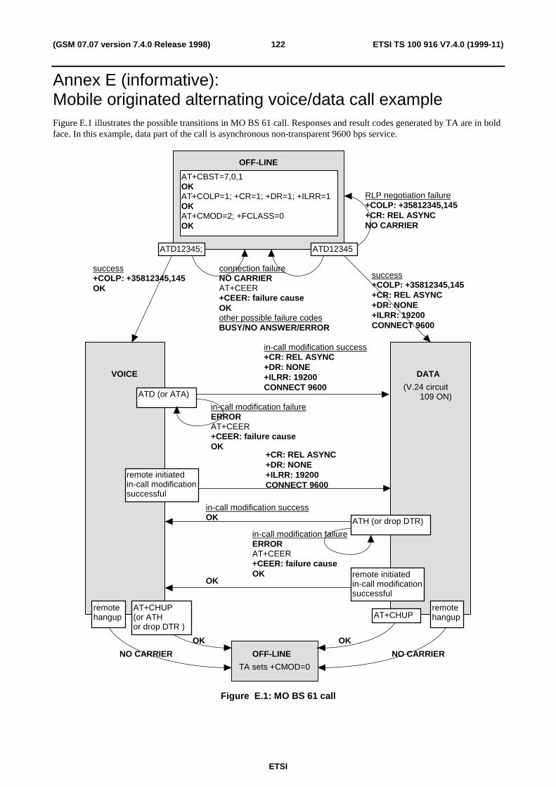
ETSI
ETSI TS 100 916 V7.4.0 (1999-11)122(GSM 07.07 version 7.4.0 Release 1998)
Annex E (informative):Mobile originated alternating voice/data call exampleFigure E.1 illustrates the possible transitions in MO BS 61 call. Responses and result codes generated by TA are in boldface. In this example, data part of the call is asynchronous non-transparent 9600 bps service.
VOICE
ATD (or ATA)
remote initiatedin-call modificationsuccessful
AT+CHUP(or ATHor drop DTR )
remotehangup
DATA
remotehangup
(V.24 circuit109 ON)
OFF-LINE
TA sets +CMOD=0
AT+CBST=7,0,1OKAT+COLP=1; +CR=1; +DR=1; +ILRR=1OKAT+CMOD=2; +FCLASS=0OK
OFF-LINE
success+COLP: +35812345,145OK
connection failureNO CARRIERAT+CEER+CEER: failure causeOKother possible failure codesBUSY/NO ANSWER/ERROR
in-call modification success+CR: REL ASYNC+DR: NONE+ILRR: 19200CONNECT 9600
in-call modification failureERRORAT+CEER+CEER: failure causeOK
+CR: REL ASYNC+DR: NONE+ILRR: 19200CONNECT 9600
AT+CHUP
OK OK
NO CARRIER NO CARRIER
ATD12345; ATD12345
RLP negotiation failure+COLP: +35812345,145+CR: REL ASYNCNO CARRIER
success+COLP: +35812345,145+CR: REL ASYNC+DR: NONE+ILRR: 19200CONNECT 9600
ATH (or drop DTR)
in-call modification successOK
remote initiatedin-call modificationsuccessful
in-call modification failureERRORAT+CEER+CEER: failure causeOK
OK
Figure E.1: MO BS 61 call

ETSI
ETSI TS 100 916 V7.4.0 (1999-11)123(GSM 07.07 version 7.4.0 Release 1998)
Annex F (informative):Mobile terminated voice followed by data call exampleFigure F.1 illustrates the possible transitions in MT BS 81 call. Responses and result codes generated by TA are in boldface. In this example, data part of the call is asynchronous non-transparent 9600 bps service.
VOICE
ATD (or ATA)
remote initiatedin-call modificationsuccessful
AT+CHUP(or ATHor drop DTR)
remotehangup
DATA
remotehangup
(V.24 circuit109 ON)
OFF-LINE
TA sets +CMOD=0
AT+CLIP=1; +CR=1; +DR=1; +ILRR=1; +CRC=1OK
+CRING: VOICE/REL ASYNC
+CLIP: +35812345,145
AT+CMOD=3; +FCLASS=0; A
OFF-LINE
successOK
connection failureNO CARRIERAT+CEER+CEER: failure causeOKgeneral failureERROR
in-call modification success+CR: REL ASYNC+DR: NONE+ILRR: 19200CONNECT 9600
in-call modification failureERRORAT+CEER+CEER: failure causeOK
+CR: REL ASYNC+DR: NONE+ILRR: 19200CONNECT 9600
ATH(or AT+CHUPor drop DTR)
OK OK
NO CARRIERNO CARRIER
Figure F.1: MT BS 81 call

ETSI
ETSI TS 100 916 V7.4.0 (1999-11)124(GSM 07.07 version 7.4.0 Release 1998)
Annex G (informative):Voice call exampleFigure G.1 illustrates the possible transitions in both MT and MO TS 11 calls. Responses and result codes generated byTA are in bold face.
VOICE call active
AT+CHUP(or ATHor drop DTR)
remotehangup
AT+CLIP=1; +CRC=1OK
+CRING: VOICE
+CLIP: +35812345,145
ATA
MT
successOK
connection failureNO CARRIERAT+CEER+CEER: failure causeOKremote busyBUSYgeneral failureERROR
OKNO CARRIER
AT+COLP=1OKATD12345;
MO with COLP
AT+COLP=0OKATD12345;
MO without COLP
connection failureNO CARRIERAT+CEER+CEER: failure causeOK
success+COLP: +35812345,145OK
(remote ring orother networkgenerated tones)
general failureERROR
call setup startedOK
connection failureNO CARRIERAT+CEER+CEER: failure causeOK
(no indicationon successfulcall setup)
Figure G.1: TS 11 calls

ETSI
ETSI TS 100 916 V7.4.0 (1999-11)125(GSM 07.07 version 7.4.0 Release 1998)
Annex H (informative):Change HistorySMG# TDoc CR R
EV
PHASE
CAT
SUBJECT WORKITEM
NEW_VERS
S20 612/96 A021 2+ B Restricted SIM access command TEI 5.1.0S20 612/96 A022 2+ C Per call CLI restriction correction TEI 5.1.0S20 612/96 A023 2+ B +COPS=? enhancement TEI 5.1.0S20 612/96 A024 2+ B +CHLD=? enhancement TEI 5.1.0s21 060/97 A025 2+ B Current call list 5.2.0s21 060/97 A026 2+ B ECT and CD support ECT, CD 5.2.0s21 060/97 A027 2+ B Extended Error codes 5.2.0s21 056/97 A028 2+ B HSCSD support HSCSD 5.2.0s21 060/97 A029 2+ B New AT IMSI command 5.2.0s21 060/97 A030 2+ B New AT Security command 5.2.0s21 060/97 A031 2+ B Single numbering scheme 5.2.0s22 415/97 A032 R97 B IrDA Telecom spec requirements 5.3.0s22 415/97 A033 2+ F Facility lock enhancements 5.3.0s22 415/97 A034 2+ F Editorial corrections 5.3.0s22 536/97 A035 R97 B Modification of AT+CAOC 5.3.0s23 97-699 A036 R96 F Deletion of codepoint for V.32bis (electronic only) 14.4 kbit/s 5.4.0s23 97-701 A037 R96 B TCH/F14.4 channel coding in HSCSD commands 14.4 kbit/s 5.4.0s23 97-702 A038 R97 B ME ringer, loudspeaker and microphone control 5.4.0s23 97-702 A039 R96 F V.120 Interworking V.120/RDI 5.4.0s23 97-702 A040 R97 B Advice of charge information from SIM 5.4.0s23 97-706 A041 R97 D Amendment in the scope Reference to 07.07 GPRS GPRS 5.4.0s23 97-702 A042 R97 B ATH and drop DTR for voice mode 5.4.0s23 97-702 A043 R97 B Preferred network list 5.4.0s24 97-922 A044 R96 D Update of alternating call figures 07.07 5.5.0s24 97-922 A045 R96 F V.120/RDI correction V.120/RDI 5.5.0s24 97-922 A047 R96 A AT+CPIN or AT+CKPD must be mandatory in some cases (phase
2+)07.07 5.5.0
s24 97-1031 A048 R97 B MUX 07.10 AT commands MUX MS-TE 5.5.0s25 98-0100 A049 R97 F AT command for MUX MS-TE alignment with 07.10 6.0.0s25 98-0100 A050 R96 A Supplementary Service control phase 2+ 5.6.0s26 98-0292 A052 R97 F GSM AT command support for GPRS GPRS 6.1.0s26 98-0293 A053 R97 F USSD command improvement TEI 6.1.0s26 98-0293 A055 R98 B New AT command ME power class control +CPWC TEI 7.0.0s27 98-0735 A065 R98 F Amendment to CR+ command GPRS 7.1.0s27 98-0737 A064 R98 F Corrections to +CR and +CREG commands TEI 7.1.0s27 98-0737 A059 R98 F Power Class +CPWC TEI 7.1.0s27 98-0736 A058 R98 B Addition of command +CHSR TEI 7.1.0s28 P-99-060 A066 R98 B Improvement of user -initiated service level upgrading HCSCD 7.2.0s28 P-99-060 A068 R98 B New command (+CCWE) used to disable/enable call meter
warning event (+CCWV)TEI 7.2.0
s28 P-99-060 A069 R98 B New AT command for handling the language setting in the ME TEI 7.2.0s28 P-99-060 A070 R98 B New AT command for enabling/disabling and changing the
greeting text (+CSGT)TEI 7.2.0
s28 P-99-060 A071 R98 B New AT command for handling voice mail numbers (+CSVM) TEI 7.2.0s28 P-99-060 A072 R98 B New AT command to playback the ring melodies in the ME
(+CRMP)TEI 7.2.0
s28 P-99-060 A073 R98 B New AT command to list all available AT commands (+CLAC) TEI 7.2.0s28 P-99-060 A067 R98 B New AT command for resetting all user data in the ME to default
values (+CMAR)TEI 7.2.0
s29 P-99-482 A081 R98 B Additional result codes for +CLIP +CCWA TEI 7.3.0s29 P-99-482 A076 R98 A Syntax error in +CHSN command TEI 7.3.0s29 P-99-482 A078 R98 D Moving AT commands to 07.07 for 07.60 handover to SMG3 /
3GPP TSG CN WG3GPRS 7.3.0
s30 P-99-675 A083 R98 A AT command - Request GPRS service 'D' GPRS 7.4.0
ETSI
ETSI TS 100 916 V7.4.0 (1999-11)126(GSM 07.07 version 7.4.0 Release 1998)
History
Document history
V7.3.0 July 1999 Publication
V7.4.0 November 1999 Publication


![SPECIFICATION & INSTALLATION GUIDE52 gsm to 450 gsm (Plain, Fine, Color Specific, Coated-G, Coated-M) 81 gsm to 350 gsm (Textured) 70 gsm to 100 gsm (Envelopes) ... Envelope Seam [1]](https://static.fdocuments.in/doc/165x107/5ebee13946efcd7097328efd/specification-installation-52-gsm-to-450-gsm-plain-fine-color-specific.jpg)