Trusted CS300 Bridge Module - Rockwell Automation
35
PD-8162 Trusted Rockwell Automation Publication PD-8162 Issue 4 Trusted CS300 Bridge Module Product Overview The CS300 Bridge Module presents a new opportunity to combine the CS300 Input / Output (I/O) structure with the latest processing and communications features of Trusted ® . Combining the two products will enable CS300 users to benefit from features such as 3-3-2-0 Processor fault tolerance, IEC 61131 programming suite, Ethernet networks, OPC, Ethernet peer to peer and remote diagnostics. The CS300 Bridge Module replaces the CS300 ICCB in the CS300 Primary chassis. Any system using the CS300 Bridge Module and Trusted Triple Modular Redundancy (TMR) Processor can also include Trusted Expanders and I/O modules forming a Hybrid system. To the Trusted TMR Processor, the Trusted and CS300 chassis appear in the same system map. All systems using Trusted TMR Processors can be seamlessly integrated together. Features: • TMR fault tolerant (3-3-2-0) operation • Dedicated hardware and software test regimes which provide very fast fault recognition and response times • Automatic fault handling without nuisance alarming • Hot replacement, self-configuration. • Interfaces to Trusted TMR Expander Bus • Front panel indicators that show module health data transmission status • Certified as non-interfering for use in IEC 61508 SIL 3 systems • Retains DIN 19250/AK6 certification of the original CS300 system
Transcript of Trusted CS300 Bridge Module - Rockwell Automation

PD-8162 Trusted
Rockwell Automation Publication PD-8162 Issue 4
Trusted CS300 Bridge Module
Product Overview
The CS300 Bridge Module presents a new opportunity to combine the CS300 Input / Output (I/O) structure with the latest processing and communications features of Trusted®.
Combining the two products will enable CS300 users to benefit from features such as 3-3-2-0 Processor fault tolerance, IEC 61131 programming suite, Ethernet networks, OPC, Ethernet peer to peer and remote diagnostics. The CS300 Bridge Module replaces the CS300 ICCB in the CS300 Primary chassis.
Any system using the CS300 Bridge Module and Trusted Triple Modular Redundancy (TMR) Processor can also include Trusted Expanders and I/O modules forming a Hybrid system. To the Trusted TMR Processor, the Trusted and CS300 chassis appear in the same system map. All systems using Trusted TMR Processors can be seamlessly integrated together.
Features:
• TMR fault tolerant (3-3-2-0) operation
• Dedicated hardware and software test regimes which provide very fast fault recognition and response times
• Automatic fault handling without nuisance alarming
• Hot replacement, self-configuration.
• Interfaces to Trusted TMR Expander Bus
• Front panel indicators that show module health data transmission status
• Certified as non-interfering for use in IEC 61508 SIL 3 systems
• Retains DIN 19250/AK6 certification of the original CS300 system

Trusted PD-8162
Rockwell Automation Publication PD-8162 Issue 4
Page intentionally left blank

Trusted CS300 Bridge Module PREFACE
Rockwell Automation Publication PD-8162 Issue 4 i
PREFACE
In no event will Rockwell Automation be responsible or liable for indirect or consequential damages resulting from the use or application of this equipment. The examples given in this manual are included solely for illustrative purposes. Because of the many variables and requirements related to any particular installation, Rockwell Automation does not assume responsibility or reliability for actual use based on the examples and diagrams.
No patent liability is assumed by Rockwell Automation, with respect to use of information, circuits, equipment, or software described in this manual.
All trademarks are acknowledged.
DISCLAIMER
It is not intended that the information in this publication covers every possible detail about the construction, operation, or maintenance of a control system installation. You should also refer to your own local (or supplied) system safety manual, installation and operator/maintenance manuals.
REVISION AND UPDATING POLICY
This document is based on information available at the time of its publication. The document contents are subject to change from time to time. The latest versions of the manuals are available at the Rockwell Automation Literature Library under "Product Information" information "Critical Process Control & Safety Systems".
TRUSTED RELEASE
This technical manual applies to Trusted Release: 3.6.1.
LATEST PRODUCT INFORMATION
For the latest information about this product review the Product Notifications and Technical Notes issued by technical support. Product Notifications and product support are available at the Rockwell Automation Support Center at http://rockwellautomation.custhelp.com
At the Search Knowledgebase tab select the option "By Product" then scroll down and select the Trusted product.
Some of the Answer ID’s in the Knowledge Base require a TechConnect Support Contract. For more information about TechConnect Support Contract Access Level and Features please click on the following link:
https://rockwellautomation.custhelp.com/app/answers/detail/a_id/50871
This will get you to the login page where you must enter your login details.

PREFACE Trusted CS300 Bridge Module
ii Issue 4 Rockwell Automation Publication PD-8162
IMPORTANT A login is required to access the link. If you do not have an account then you can create one using the "Sign Up" link at the top right of the web page.
DOCUMENTATION FEEDBACK
Your comments help us to write better user documentation. If you discover an error, or have a suggestion on how to make this publication better, send your comment to our technical support group at http://rockwellautomation.custhelp.com

Trusted CS300 Bridge Module PREFACE
Rockwell Automation Publication PD-8162 Issue 4 iii
SCOPE
This manual specifies the maintenance requirements and describes the procedures to assist troubleshooting and maintenance of a Trusted system.
WHO SHOULD USE THIS MANUAL
This manual is for plant maintenance personnel who are experienced in the operation and maintenance of electronic equipment and are trained to work with safety systems.
SYMBOLS
In this manual we will use these notices to tell you about safety considerations.
SHOCK HAZARD: Identifies an electrical shock hazard. If a warning label is fitted, it can be on or inside the equipment.
WARNING: Identifies information about practices or circumstances that can cause an explosion in a hazardous environment, which can cause injury or death, property damage or economic loss.
ATTENTION: Identifies information about practices or circumstances that can cause injury or death.
CAUTION: Identifies information about practices or circumstances that can cause property damage or economic loss.
BURN HAZARD: Identifies where a surface can reach dangerous temperatures. If a warning label is fitted, it can be on or inside the equipment.
This symbol identifies items which must be thought about and put in place when designing and assembling a Trusted controller for use in a Safety Instrumented Function (SIF). It appears extensively in the Trusted Safety Manual.
IMPORTANT Identifies information that is critical for successful application and understanding of the product.
NOTE Provides key information about the product or service.
TIP Tips give helpful information about using or setting up the equipment.

PREFACE Trusted CS300 Bridge Module
iv Issue 4 Rockwell Automation Publication PD-8162
WARNINGS AND CAUTIONS
WARNING: EXPLOSION RISK
Do not connect or disconnect equipment while the circuit is live or unless the area is known to be free of ignitable concentrations or equivalent
AVERTISSEMENT - RISQUE D’EXPLOSION
Ne pas connecter ou déconnecter l’équipement alors qu’il est sous tension, sauf si l’environnement est exempt de concentrations inflammables ou équivalente
MAINTENANCE
Maintenance must be carried out only by qualified personnel. Failure to follow these instructions may result in personal injury.
CAUTION: RADIO FREQUENCY INTERFERENCE
Most electronic equipment is influenced by Radio Frequency Interference. Caution should be exercised with regard to the use of portable communications equipment around such equipment. Signs should be posted in the vicinity of the equipment cautioning against the use of portable communications equipment.
CAUTION:
The module PCBs contains static sensitive components. Static handling precautions must be observed. DO NOT touch exposed connector pins or attempt to dismantle a module.

Trusted CS300 Bridge Module PREFACE
Rockwell Automation Publication PD-8162 Issue 4 v
ISSUE RECORD
Issue Date Comments
1 Apr 2008 First Issue
2 Feb 2010 TC-322 details
3 Jul 2015 Converted document to Rockwell branding layout
Clarified certification status and corrected Operating Humidity range
4 Jun 2016 Correction of Operating Temperature specification, typographical errors and updated to incorporate IEEE standards.

PREFACE Trusted CS300 Bridge Module
vi Issue 4 Rockwell Automation Publication PD-8162
Page intentionally left blank

Trusted CS300 Bridge Module Table of Contents
Rockwell Automation Publication PD-8162 Issue 4 1
Table of Contents
1. Description ............................................................................................................ 3
1.1. Overview .................................................................................................................................... 3 1.2. Power Distribution ..................................................................................................................... 4 1.3. Communication Buses ................................................................................................................ 4
1.3.1. The Trusted to CS300 Primary Chassis ............................................................................... 4 1.3.2. Inter-Module Link (IML) ..................................................................................................... 4
1.4. Function ..................................................................................................................................... 4
2. Installation ............................................................................................................ 5
2.1. Module ....................................................................................................................................... 5 2.2. TC-322-02 Interface Cable Assembly ......................................................................................... 6 2.3. Module Configuration ................................................................................................................ 8
3. Application ............................................................................................................ 9
3.1. System Configuration ................................................................................................................. 9 3.2. Board Definitions ..................................................................................................................... 14
3.2.1. Module – 8162 (Bridge Module) ...................................................................................... 14 3.2.2. Module – bic (Bus Interface Controller) ........................................................................... 15 3.2.3. Module – pi632 / pi732 (Analogue Input Module) .......................................................... 16 3.2.4. Module – pi641 / pi741 (Analogue Output Module) ....................................................... 17 3.2.5. Module – pi616_5 / pi616_9 / pi716 / pi717 (Digital Input Module) ............................... 19 3.2.6. Module – pi626 / pi726 (Digital Output Module) ............................................................ 20 3.2.7. Module – dmx_m (De-Multiplexed Display Driver).......................................................... 21 3.2.8. Module – dmx_o (De-Multiplexed Display Driver Card) .................................................. 22
4. Operation ............................................................................................................ 23
4.1. Front Panel Indicators and Controls ........................................................................................ 24 4.1.1. Tx & Rx Indicators ............................................................................................................. 24 4.1.2. Health Indicator ................................................................................................................ 24 4.1.3. On-Line Indicator and Switch ........................................................................................... 24
5. Fault Finding and Maintenance ............................................................................. 25
6. Specifications ....................................................................................................... 27

Table of Contents Trusted CS300 Bridge Module
2 Issue 4 Rockwell Automation Publication PD-8162
Page intentionally left blank

Trusted CS300 Bridge Module 1. Description
Rockwell Automation Publication PD-8162 Issue 4 3
1. Description
1.1. Overview
The CS300 Bridge Module enables connection between a CS300 I/O sub system and the Trusted TMR Processor. Three CS300 Bridge modules replace the three ICCB modules in a CS300 primary chassis.
The certification of the original CS300 system to DIN 19250/AK6 will be maintained for applications migrated to the Trusted Controller in accordance with this manual, the Trusted TMR System Safety Manual and the guidance in NAMUR 126.
The Bridge module has a fast serial ("Hotlink") interface that transfers command and response packets between the two product families via the Trusted Expander Bus. The module uses a Field Programmable Gate Array (FPGA) for decoding instructions from the Trusted TMR processor, accessing the specified CS300 I/O module and returning any data requested.
Command data received by the three Bridge modules and responses to the Trusted TMR Processor are synchronized in accordance with the Lock Step operational characteristics of the Trusted Expander Bus. For this reason, the three bridge modules share their data and arrange their response packets in the same order for simultaneous transmission. The clock signal received from the Expander Bus is used to ensure that data from all three Bridge modules is transmitted on the same clock edge.
The Trusted TMR processor stores and executes the application program, scans and updates the CS300 I/O modules and detects system faults. Each of the three slices of the TMR Processor executes the application program independently, but in lock-step synchronization with the other two.
All CS300 I/O actions are executed by polling only. This means that all CS300 I/O modules are supported, with the exception of Serial I/O modules (which generate interrupts). All communications to workstations and DCS systems are enabled through the Trusted Communications Interfaces.
FCR A
FCR A Trusted Expander Interface Module
hotlink receiver FPGA
(C)
(B)
Bridge Module (A)
Bridge Module (B)
Bridge Module (C)
hotlink transmitter
CS300 Backplane
Expansion Bus (TC-322-02 Cable) (TC-324-02 Board)
Inter Module Link
(A)
Trusted™ Main Chassis
CS300 Main Chassis
to CS300 I/O Modules
Figure 1 Block Diagram showing interface between Trusted system and CS300 I/O

1. Description Trusted CS300 Bridge Module
4 Issue 4 Rockwell Automation Publication PD-8162
1.2. Power Distribution
Each of the Bridge modules is powered from triple redundant PSUs (situated in a separate chassis) that support the main I/O chassis with 5 V, 12 V & ±20 Vdc supplies and up to three CS300 extension chassis with 12 V and ±20 Vdc only.
1.3. Communication Buses
1.3.1. The Trusted to CS300 Primary Chassis
Communication between the Trusted Expander Interface Module and the CS300 Primary Chassis is via one of a possible four or seven triplicated two-way interface cables. A single backplane connector card routes the individual links in the cable to the three Bridge modules. Data voting is provided at the Expander Module Interface to ensure that cable faults are detected.
The link handles the following triplicated signals:
• Data - Serial bi-directional bus.
• Control - Bus clocks, module-enables and bus direction control.
• Slot - Indicating the CS300 I/O slot position to the Bridge.
• Expander Chassis ID - 4 bit Trusted chassis address code.
1.3.2. Inter-Module Link (IML)
When returning data for Trusted Read requests, I/O Module data received by each Bridge module is shared with the other two using the serial IML via the backplane. The three sets of data are then arranged sequentially into the response packet for Trusted. The IML is not used during Write requests.
1.4. Function
When an I/O access is to be performed, the Trusted TMR Processor issues a command packet to an Expander Interface Module. The Expander Interface decodes the chassis address and transmits the packet through an Expander bus to receivers in the 8162 Bridge modules.
For short distances of a few metres, a twisted-pair copper cable is used, whilst on longer runs the copper cable is connected to three T8312 fibre optic units at each end of three pairs (Tx and Rx) of fibre optic cable. The Bridge modules, receiving the command signals, decode the packet.
The Bridge modules then implement the read or write access on the CS300 I/O module selected and return a response packet via the serial expander bus. The packet will contain both data and diagnostic information.

Trusted CS300 Bridge Module 2. Installation
Rockwell Automation Publication PD-8162 Issue 4 5
2. Installation
2.1. Module
Each of the three Bridge modules replaces one of the CS300 ICCB modules. Figure 2 shows the module. The replacement must be carried out with the system offline.
The modules consist of a single Printed Circuit Board (PCB) assembly.
Figure 2 8162 Bridge Module

2. Installation Trusted CS300 Bridge Module
6 Issue 4 Rockwell Automation Publication PD-8162
2.2. TC-322-02 Interface Cable Assembly
The interface cable connects from the Trusted Interface Adapter T8312 to an identical 12 way socket on the interface cable connector card.
Figure 3 TC-322-02 Interface Cable Assembly
Figure 4 CS300 Main Chassis Rear View
Figure 4 shows the interface cable connector card (top left) fitted to the rear of the CS300 controller chassis which is connected to the Trusted Expander Interface adapter via the TC322-02 interface cable (braided cable at top left).
Connectors J1-3 on the TC-324-02 card plug into the three 26-way headers on the CS300 backplane. The expander cable TC-322-02 from the Trusted Expander Interface plugs into 12-way socket J4.

Trusted CS300 Bridge Module 2. Installation
Rockwell Automation Publication PD-8162 Issue 4 7
Figure 5 Trusted Controller Chassis Rear View
Figure 5 shows a four socket version of the T8312 Expander Interface Adapter with a TC-301-01 cable attached, which connects to a Trusted expander chassis. The Expander Interface Adapter has four or seven connections available to individual Trusted Expander chassis or to the CS300 controller chassis using the TC-322-02 Interface Cable Assembly.

2. Installation Trusted CS300 Bridge Module
8 Issue 4 Rockwell Automation Publication PD-8162
2.3. Module Configuration
Figure 6 CS300 Chassis Backplane
The Bridge module requires minimum configuration, namely the setting of three sets of jumpers 0 to 3 to define the chassis address to Trusted. These are situated on the CS300 chassis backplane as shown here.
The four backplane jumpers 0,1,2,3 (A,B,C) represent the binary address bits 1,2,4 & 8 respectively. A fitted jumper signals a binary digit ‘1’. The address is set to between 2 and 8. On the first CS300 chassis (containing the CS300 Bridge Modules), fit jumper 1 (A,B,C) to represent Trusted address '2'. The jumpers on all three sets must be set to the same address. Leave the jumpers as they were on the other CS300 chassis. It is usual to attach the chassis with address 2 to the first Expander Interface Adapter socket, for both Trusted chassis and CS300 chassis. This makes the software configuration easier.

Trusted CS300 Bridge Module 3. Application
Rockwell Automation Publication PD-8162 Issue 4 9
3. Application
All CS300 I/O modules are configured using the IEC 61131 application Toolset provided with Trusted. This configuration requires entries in the System Configuration (System.INI) for the chassis and modules and their hardware operational parameters, and also in the workbench I/O connection table, for software settings and data connection.
3.1. System Configuration
All Trusted systems need a system configuration file, specifying the chassis and modules in the system. For Trusted /CS300 hybrid systems, a T8311 Expander Interface is required in the Trusted controller chassis, as for Trusted only systems. An example with Expander Interfaces in slots 1 and 2 (companion slots) and communications interfaces in slots 7 and 8 is shown below. For details of the System Configuration Tool please refer to product description PD-T8082.
Figure 7 Trusted Processor Chassis with Expander Interface
The CS300 chassis are attached to the Expander Interface as if they were Trusted expander chassis, but the various chassis options for Triguard and CS300 are provided on the ‘Insert New Chassis’ dialog. Right-click on the background of the configurator window to insert a new chassis.

3. Application Trusted CS300 Bridge Module
10 Issue 4 Rockwell Automation Publication PD-8162
Figure 8 Insert New Chassis
The first chassis to be created is a CS300 8162. This includes the bridge modules in place of the CS300 processors. Choose typeCS300 8162 and select a logical chassis number. This chassis number will define the switch configuration described in Section 2.3.
Figure 9 CS300 Main Chassis
The chassis should then be allocated to the Trusted Expander Interface module. Left-click on the left or right end of the CS300 8162 chassis to open the Chassis Connection dialog. Select the slot number of the left-hand Expander Interface module.

Trusted CS300 Bridge Module 3. Application
Rockwell Automation Publication PD-8162 Issue 4 11
Figure 10 Chassis Connection
On closing this dialog, the CS300 8162 chassis should have a blue flash symbol on the left. The right hand side shows the chassis address as:
< Trusted expander Interface slot> - <Expander socket number> - <CS300 chassis number>
Figure 11 Connected Chassis
Left-click on the left or right end of the CS300 8162 chassis to open the Chassis Connection dialog again. The ‘Jumper Config’ button now demonstrates how to set the backplane jumpers.

3. Application Trusted CS300 Bridge Module
12 Issue 4 Rockwell Automation Publication PD-8162
Figure 12 Jumper Setting
This chassis then links into the extension chassis BIC, which is linked to the main CS300 8162 chassis by ribbon cables.
To add a BIC chassis, right click again on the background and select CS300 BIC. The switch settings on these chassis should not be changed from their old configuration in the CS300 system. Select the 8162 chassis to connect the new chassis to (Parent 8162 Chassis Number), and enter the chassis number as configured on the chassis address switches on the BIC chassis (Triguard Chassis Number). Closing this window and left-clicking on the chassis ends will show the Jumper Config button, which will confirm the switch settings that have been selected.
Figure 13 BIC Chassis Addressing
The chassis will now show its address on the right end as:
< Trusted expander Interface slot> - <Expander socket number> - <CS300 chassis number>
e.g. 1-2-2 in the above example.

Trusted CS300 Bridge Module 3. Application
Rockwell Automation Publication PD-8162 Issue 4 13
Having added all the chassis in the system, the next step is to insert modules. For each module, right-click on the appropriate chassis slot. Select the module from the list.
Figure 14 CS300 Modules
On left-clicking the module, the module options are displayed.
Figure 15 Module Options
If the module has been allocated a Hot Repair partner slot, so that the partner module can take over on failure, then check the Hot Repair Module option. The configurator will automatically allocate the next appropriate slot, but this may be edited. There is no need to insert a module for the hot repair slot; the configurator will add this automatically There is also no need to edit the options for the hot repair module. The hot repair partnership is set up using the interlinking ribbon cable between the modules.

3. Application Trusted CS300 Bridge Module
14 Issue 4 Rockwell Automation Publication PD-8162
The ‘Mode’ is included for PI727 modules which can be set to 3-2-1 or 3-2-0 operation.
For output modules, an input module may be configured to monitor the outputs as a diagnostic feedback. Where this is required, check the Enable Monitor option and select the chassis and slot of the input module. For analogue output modules, also select the monitor channel.
With monitoring enabled, it is possible to add Line Fault Detection (LFD) testing. Complete testing is only possible with two online output cards (in a hot repair configuration).
To allow the system to run with a module absent, check ‘Simulate’.
Ensure that the options selected are as configured in the original application.
3.2. Board Definitions
There are no restrictions in the order of the boards set out in the connection table except in cases where TM117-DMX (64-Channel De-Multiplexed Driver) termination cards are configured in the system. These have to be defined before any CS300I/O modules are specified. The DMX cards are driven from the Trusted processor module’s serial ports.
It is also general convention to specify the Trusted main processor at the head of the connection table.
In a true hybrid system including Trusted I/O modules, conventions for entering the various board definitions have to be referred to in the associated Product Description.
3.2.1. Module – 8162 (Bridge Module)
DESCRIPTION
This definition provides module status for a 8162 primary chassis expansion interface module that provides an expansion bridge from Trusted to CS300 systems.
The logical module accounts for the 3 physical modules FCR-A, FCR-B and FCR-C.
OEM PARAMETERS
OEM parameter Valid numbers Description
CHASSIS 2-29 Logical chassis number allocated to the primary CS300 chassis in which the 8162 modules are placed.
SLOT 16 Logical slot within the Primary CS300 chassis by which the Trusted system identifies the 8162 module. This cannot be configured.
PHYSICAL MODULE
RACK 1: [STATUS] - 6 BOOL Inputs
Variable 1: TRUE = Logical module responding
Variable 2: TRUE = FCR-A faulted or not responding
Variable 3: TRUE = FCR-B faulted or not responding
Variable 4: TRUE = FCR-C faulted or not responding

Trusted CS300 Bridge Module 3. Application
Rockwell Automation Publication PD-8162 Issue 4 15
RACK 2: [INFO] - 12 ANALOGUE Inputs
Word 1: FCR-A fault code (see note 1)
Word 2: FCR-B fault code (see note 1)
Word 3: FCR-C fault code (see note 1)
Word 4: FCR-A hot-link error count
Word 5: FCR-B hot-link error count
Word 6: FCR-C hot-link error count
Word 7: FCR-A IML own-link error count
Word 8: FCR-A IML down-link error count
Word 9: FCR-A IML up-link error count
Word 10: FCR-B IML own-link error count
Word 11: FCR-B IML down-link error count
Word 12: FCR-B IML up-link error count
Word 13: FCR-C IML own-link error count
Word 14: FCR-C IML down-link error count
Word 15: FCR-C IML up-link error count
Note 1 - Fault Codes 0 : No fault 1 : Local backplane fault 2 : Local expansion bus fault 3 : Common fault (applies to both local backplane and expansion buses)
3.2.2. Module – bic (Bus Interface Controller)
DESCRIPTION
This definition provides module status for a PI 651/751 Bus Interface Controller that provides expansion interface for secondary chassis in the CS300 system.
The logical module accounts for the 3 physical modules FCR-A, FCR-B and FCR-C.
OEM PARAMETERS:
OEM parameter Valid numbers Description
CHASSIS 2-29 Logical chassis number allocated to the local secondary CS300 chassis in which the BIC modules are placed.
SLOT 16 Logical slot within the local secondary CS300 chassis by which the Trusted system identifies the BIC module. This cannot be configured.

3. Application Trusted CS300 Bridge Module
16 Issue 4 Rockwell Automation Publication PD-8162
PHYSICAL MODULE:
RACK 1: [STATUS] - 10 BOOL Inputs
Variable 1: FALSE (Not used)
Variable 2: TRUE = FCR-A faulted
Variable 3: TRUE = FCR-B faulted
Variable 4: TRUE = FCR-C faulted
Note: The status of BIC FCR's can only be determined by the discrepancy status of accesses performed to I/O modules within the chassis of the BIC. If no such modules exist or if no BIC FCR's are fitted then no faults can be reported.
3.2.3. Module – pi632 / pi732 (Analogue Input Module)
DESCRIPTION
This definition will open a single PI632 or PI732.
OEM PARAMETERS
OEM parameter Valid numbers Description
CHASSIS 2-29 Logical chassis and slot number where the CIO_AI is located.
SLOT 1-15
PHYSICAL MODULE:
RACK 1: (AI)
16 INTEGER inputs
RACK 2: (DIAG)
2 INTEGER inputs
Word 1 Diagnostic bits
bit 0 Slice A
=1 slice is not responding or there is an error
=0 slice is responding
bit 1 Slice B
=1 slice is not responding or there is an error
=0 slice is responding
bit 2 Slice C
=1 slice is not responding or there is an error
=0 slice is responding

Trusted CS300 Bridge Module 3. Application
Rockwell Automation Publication PD-8162 Issue 4 17
bit 3 Module offline or missing
=1 offline or missing
=0 online
bit 4 Single slot hot repair
=1 in progress
=0 not in progress
bit 5 Discrepancy errors
=1 faults detected
=0 no faults detected
Word 2 Slot number of active module
RACK 3: (FAULTS)
1 INTEGER inputs
Word 1 Discrepancy errors, channels 1-16 (bit 0 = channel 1)
3.2.4. Module – pi641 / pi741 (Analogue Output Module)
DESCRIPTION
This definition will open a single PI641 or PI741.
OEM PARAMETERS
OEM parameter Valid numbers Description
CHASSIS 2-29 Logical chassis and slot number where the CIO_AO is located.
SLOT 1-15
PHYSICAL MODULE:
RACK 1: (AO)
4 INTEGER outputs
RACK 2: (DIAG)
2 INTEGER inputs
Word 1 Diagnostic bits
bit 0 Slice A
=1 slice is not responding or there is an error
=0 slice is responding
bit 1 Slice B
=1 slice is not responding or there is an error

3. Application Trusted CS300 Bridge Module
18 Issue 4 Rockwell Automation Publication PD-8162
=0 slice is responding
bit 2 Slice C
=1 slice is not responding or there is an error
=0 slice is responding
bit 3 Module offline or missing
=1 offline or missing
=0 online
bit 4 Single slot hot repair
=1 in progress
=0 not in progress
bit 5 Discrepancy errors
=1 faults detected
=0 no faults detected
Word 2 Slot number of active module
RACK 3: (FAULTS)
2 INTEGER inputs
Word 1 Discrepancy errors, channels 1-4 (bit 0 = channel 1)
Word 2 LFD errors, channels 1-4 (bit 0 = channel 1)
RACK 4: (CALIB)
4 BOOLEAN outputs (one per channel) which determine if the AO output data is taken from RACK 1 (AO) or from RACKs 5-7 (CALIB_x).
=0, output data taken from RACK 1 (AO)
=1, output data taken from RACKs 5-7 (CALIB_x)
RACK 5: (CALIB_A)
4 INTEGER outputs
Output data used for Slice A on the AO module. Only used if the corresponding Boolean output in RACK 4 (CALIB) is TRUE.
RACK 6: (CALIB_B)
4 INTEGER outputs
Output data used for Slice B on the AO module. Only used if the corresponding boolean output in RACK 4 (CALIB) is TRUE.
RACK 7: (CALIB_C)
4 INTEGER outputs

Trusted CS300 Bridge Module 3. Application
Rockwell Automation Publication PD-8162 Issue 4 19
Output data used for Slice C on the AO module. Only used if the corresponding boolean output in RACK 4 (CALIB) is TRUE.
Notes: Discrepancy errors will only be checked if the AO module has a configured AI monitor module. Discrepancy errors indicate a difference between the output value on an AO and the voted input value on the AI monitor. LFD errors will only be checked if the AO module has a configured AI monitor module and LFD testing is enabled on that AO module. The calibration racks (4-7) can be used to aid calibration of the D/A converters on the AO modules. They allow different values to be sent to each slice's D/A converter, allowing each to be calibrated individually.
3.2.5. Module – pi616_5 / pi616_9 / pi716 / pi717 (Digital Input Module)
DESCRIPTION
This definition will open a single PI616 type 5 or PI616 type 9 or PI716 or PI717.
OEM PARAMETERS
OEM parameter Valid numbers Description
CHASSIS 2-29 Logical chassis and slot number where the module is located.
SLOT 1-15
PHYSICAL MODULE:
RACK 1: (DI)
32 BOOLEAN inputs
RACK 2: (DIAG)
2 INTEGER inputs
Word 1 Diagnostic bits
bit 0 Slice A
=1 slice is not responding or there is an error
=0 slice is responding
bit 1 Slice B
=1 slice is not responding or there is an error
=0 slice is responding
bit 2 Slice C
=1 slice is not responding or there is an error
=0 slice is responding
bit 3 Module offline or missing
=1 offline or missing
3. Application Trusted CS300 Bridge Module
20 Issue 4 Rockwell Automation Publication PD-8162
=0 online
bit 4 Single slot hot repair
=1 in progress
=0 not in progress
bit 5 Discrepancy errors
=1 faults detected
=0 no faults detected
Word 2 Slot number of active module
RACK 3: (FAULTS)
2 INTEGER inputs
Word 1 Discrepancy errors, channels 1-16 (bit 0 = channel 1)
Word 2 Discrepancy errors, channels 17-32 (bit 0 = channel 17)
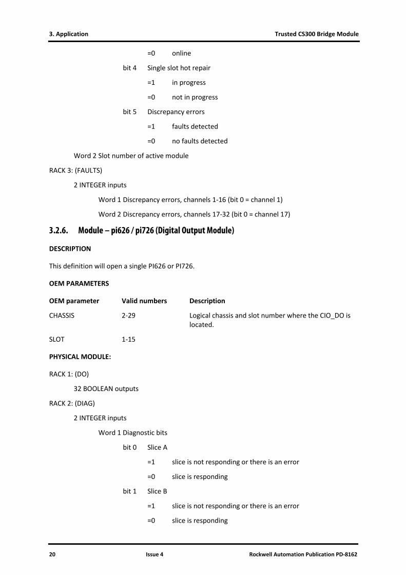
3.2.6. Module – pi626 / pi726 (Digital Output Module)
DESCRIPTION
This definition will open a single PI626 or PI726.
OEM PARAMETERS
OEM parameter Valid numbers Description
CHASSIS 2-29 Logical chassis and slot number where the CIO_DO is located.
SLOT 1-15
PHYSICAL MODULE:
RACK 1: (DO)
32 BOOLEAN outputs
RACK 2: (DIAG)
2 INTEGER inputs
Word 1 Diagnostic bits
bit 0 Slice A
=1 slice is not responding or there is an error
=0 slice is responding
bit 1 Slice B
=1 slice is not responding or there is an error
=0 slice is responding

Trusted CS300 Bridge Module 3. Application
Rockwell Automation Publication PD-8162 Issue 4 21
bit 2 Slice C
=1 slice is not responding or there is an error
=0 slice is responding
bit 3 Module offline or missing
=1 offline or missing
=0 online
bit 4 Single slot hot repair
=1 in progress
=0 not in progress
bit 5 Discrepancy errors
=1 faults detected
=0 no faults detected
bit 6 LFD faults
=1 faults detected
=0 no faults detected
Word 2 Slot number of active module
RACK 3: (FAULTS)
4 INTEGER inputs
Word 1 Discrepancy errors, channels 1-16 (bit 0 = channel 1)
Word 2 Discrepancy errors, channels 17-32 (bit 0 = channel 17)
Word 3 LFD errors, channels 1-16 (bit 0 = channel 1)
Word 4 LFD errors, channels 17-32 (bit 0 = channel 17)
Notes: Discrepancy errors will only be checked if the DO module has a configured DI monitor module. Discrepancy errors indicate a difference between the output value on a DO and the voted input value on the DI monitor.
3.2.7. Module – dmx_m (De-Multiplexed Display Driver)
DESCRIPTION
This definition will open a single TM117-DMX Master.
OEM PARAMETERS
OEM parameter Valid numbers Description
PORT_A 1-3 MP serial port number for the DMX chain primary link

3. Application Trusted CS300 Bridge Module
22 Issue 4 Rockwell Automation Publication PD-8162
PORT_B 0 or 2/3 MP serial port number for the DMX chain secondary link (=0 disables the secondary link)
PHYSICAL MODULE:
RACK 1: (DMX)
1 BOOLEAN output
not used
Notes: The dmx_m module must be defined before the dmx_o modules.
3.2.8. Module – dmx_o (De-Multiplexed Display Driver Card)
DESCRIPTION
This definition will open a single TM117-DMX output card.
OEM PARAMETERS
OEM parameter Valid numbers Description
DMX_BOARD_ID 1-64 DMX board ID
PHYSICAL MODULE:
RACK 1: (DMX)
64 INTEGER outputs
Valid values:
0 = Off
1 = Slow flash on/off
2 = Fast flash on/off
3 = On (steady)
4+ = Invalid (will result in output being off)
Notes: The dmx_m module must be defined before the dmx_o modules.

Trusted CS300 Bridge Module 4. Operation
Rockwell Automation Publication PD-8162 Issue 4 23
4. Operation
Figure 16 Front Panel Layout

4. Operation Trusted CS300 Bridge Module
24 Issue 4 Rockwell Automation Publication PD-8162
4.1. Front Panel Indicators and Controls
4.1.1. Tx & Rx Indicators
Flashing amber Light Emitting Diodes (LEDs) indicate active transmit and receive communications on the Expander Bus.
4.1.2. Health Indicator
A steady green Light Emitting Diode (LED) indicates a fault-free Bridge module; an extinguished LED indicates a fault.
4.1.3. On-Line Indicator and Switch
Raising and releasing the on/off-line switch momentarily takes the module off-line, which is mirrored by the steady On/Off state of the amber On-Line LED. Repeating the action brings the module back on-line.
Prior to hot-swapping the module for repair, it should be taken off-line using this feature to ensure a clean exit from the system. The replacement module is then placed on-line using the switch.

Trusted CS300 Bridge Module 5. Fault Finding and Maintenance
Rockwell Automation Publication PD-8162 Issue 4 25
5. Fault Finding and Maintenance
The Trusted TMR Processor provides fault monitoring, self-test and diagnostics functions.
Fault Detection within a Trusted / CS300 system can be categorized into four regions:
• Trusted TMR Processor and Expander Hardware
• CS300 Bridge Hardware
• CS300 I/O Hardware
• User Application
Using current Trusted methods for detection of faults, the TMR Processor can monitor for failures up to the Expander section. The Main Processor (MP) is also able to separate Bridge hardware faults from CS300 I/O module faults. The CS300 I/O modules carry out on-board diagnostic tests which are relayed back to the TMR Processor via the Bridge module.
The user application can also be programmed to read error flags in the I/O module fault registers to annunciate the detection of module faults. Second faults that leave the system unable to confirm healthy operation will result in the TMR Processor stopping all communication with the 8162 bridge modules, ensuring that critical outputs go to a safe state when the internal watchdogs time out.
5. Fault Finding and Maintenance Trusted CS300 Bridge Module
26 Issue 4 Rockwell Automation Publication PD-8162
Page intentionally left blank

Trusted CS300 Bridge Module 6. Specifications
Rockwell Automation Publication PD-8162 Issue 4 27
6. Specifications
Supply Voltage 5.4 Vdc ±5 %
Heat Dissipation 3 Wmax
Operating Temperature (convection cooling) 0 °C to +60 °C (+32 °F to +140 °F)
Storage Temperature -25 °C to +70 ºC (-13 °F to +158 °F)
Relative Humidity range (operating, storage and transport)
10 % – 95 %, non-condensing
Vibration 10 to 500 Hz peak to peak 1 g
Shock Operating:11 ms, ½ sine wave 15 g
Environmental Specifications Refer to Document 552517
Height: 290 mm (11.4 in)
Width: 37 mm (1.5 in)
Depth: 370 mm (14.6 in)
Weight (approx.) 760 g (1.7 lb)