Trusses - site.iugaza.edu.pssite.iugaza.edu.ps/marafa/files/Chapter-3-2019.pdfStability For plane...
87
Chapter 3 Chapter 3 Trusses Trusses
Transcript of Trusses - site.iugaza.edu.pssite.iugaza.edu.ps/marafa/files/Chapter-3-2019.pdfStability For plane...

Chapter 3Chapter 3
TrussesTrusses

Trusses in Building

Trusses Types for Building
Structural Analysis IDr. Mohammed Arafa


6 Chapter 2 Dr. Mohammed Arafa


Truss Bridge

Truss Bridge

Truss Bridge Types


Assumptions for Design
All members are connected at both ends by smooth
frictionless pins.
All loads are applied at joints (member weight is
negligible)
Centroids of all joint members coincide at the joint.
All members are straight.
All load conditions satisfy Hookeís law.

Classification of coplanar TrussSimple Truss

Compound Truss

Stability of Compound Truss

Complex Truss

Determinacy
For plane truss
If b+r = 2j statically determinate
If b+r > 2j statically indeterminate
Where
b = number of bars
r = number of external support reaction
j = number of joints

Stability
For plane truss
If b+r < 2j unstable
The truss can be statically determinate or indeterminate (b+r >=2j)
but unstable in the following cases:
External Stability: truss is externally unstable if all of its
reactions are concurrent or parallel
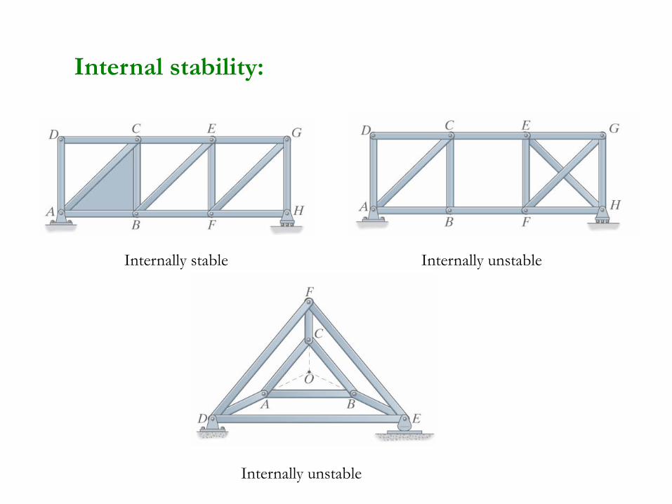
Internal stability:
Internally stable Internally unstable
Internally unstable

Classify each of the truss as stable , unstable,
statically determinate or indeterminate.
Stable & edeterminat Statically
22)11(22
22
11 3 19
j
rb
jrb
Stable & ateindetermin Statically
18)9(22
19
9 4 15
j
rb
jrb
Structural Analysis IDr. Mohammed Arafa

Stable & edeterminat Statically
12)6(22
12
6 3 9
j
rb
jrb
Unstable
16)8(22
15
8 3 12
j
rb
jrb
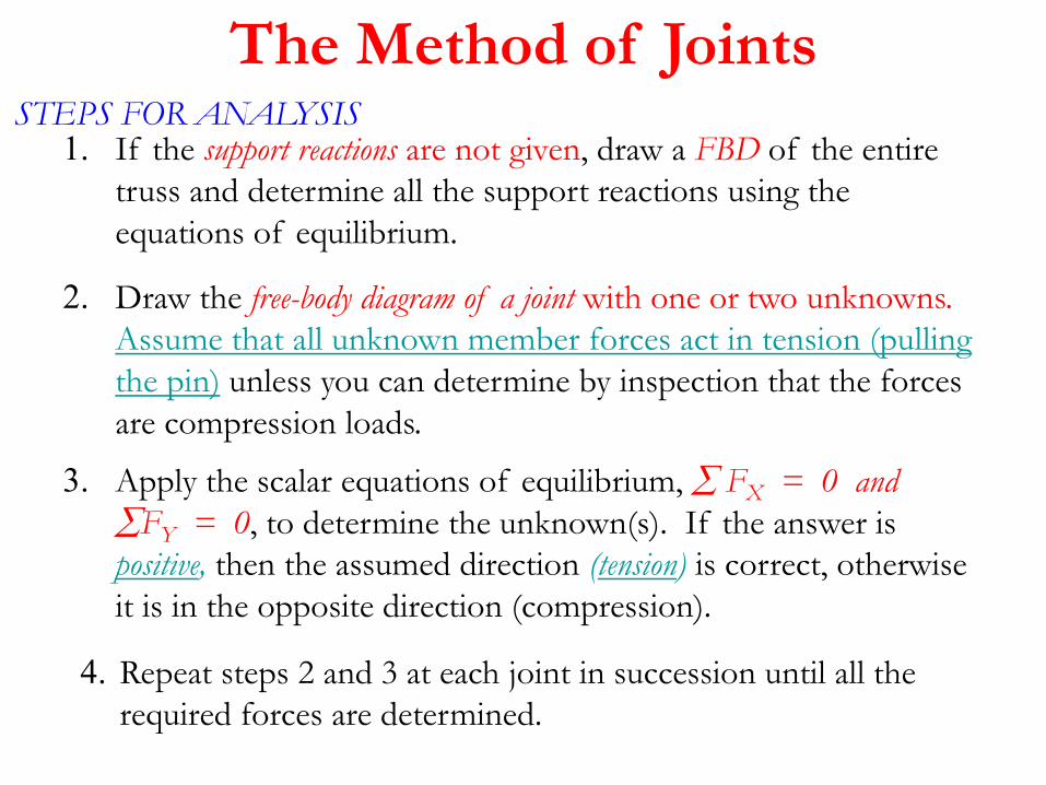
STEPS FOR ANALYSIS1. If the support reactions are not given, draw a FBD of the entire
truss and determine all the support reactions using the
equations of equilibrium.
2. Draw the free-body diagram of a joint with one or two unknowns.
Assume that all unknown member forces act in tension (pulling
the pin) unless you can determine by inspection that the forces
are compression loads.
3. Apply the scalar equations of equilibrium, FX = 0 and
FY = 0, to determine the unknown(s). If the answer is
positive, then the assumed direction (tension) is correct, otherwise
it is in the opposite direction (compression).
4. Repeat steps 2 and 3 at each joint in succession until all the
required forces are determined.
The Method of Joints

The Method of Joints
Structural Analysis IDr. Mohammed Arafa
Example 1

Example 2Solve the following truss

Example 2Solve the following truss

0;
4 sin 30 0 8 C
0;
8cos30 0 6.93 T
y
AG AG
x
AB AB
F
F F KN
F
F F KN

0;
sin 30 3cos30 0 3.0 C
0;
8 3sin 30 3cos30 0 5.0 C
y
GB GB
x
GF GF
F
F F kN
F
F F kN
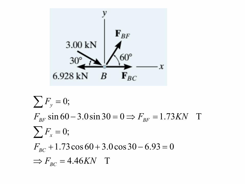
0;
sin 60 3.0sin 30 0 1.73 T
0;
1.73cos 60 3.0cos30 6.93 0
4.46 T
y
BF BF
x
BC
BC
F
F F KN
F
F
F KN

ProblemDetermine the force in each member

Zero Force Member
1- If a joint has only two non-colinear members and there is no
external load or support reaction at that joint, then those two
members are zero-force members

Zero Force Member2- If three members form a truss joint for which two of the
members are collinear and there is no external load or reaction at that
joint, then the third non-collinear member is a zero force member.

Example 3Find Zero force member of the following truss

Method of Section

The Method of Section

1. Decide how you need to “cut” the truss. This is based on:
a) where you need to determine forces, and, b) where the total
number of unknowns does not exceed three (in general).
2. Decide which side of the cut truss will be easier to work with
(minimize the number of reactions you have to find).
3. If required, determine the necessary support reactions by
drawing the FBD of the entire truss and applying the E. of E.
The Method of SectionSTEPS FOR ANALYSIS

4. Draw the FBD of the selected part of the cut truss. We need to
indicate the unknown forces at the cut members. Initially we
assume all the members are in tension, as we did when using the
method of joints. Upon solving, if the answer is positive, the
member is in tension as per our assumption. If the answer is
negative, the member must be in compression. (Please note that you
can also assume forces to be either tension or compression by inspection as was
done in the previous example above.)
5. Apply the equations of equilibrium (EofE) to the selected cut
section of the truss to solve for the unknown member forces.
Please note that in most cases it is possible to write one equation
to solve for one unknown directly.

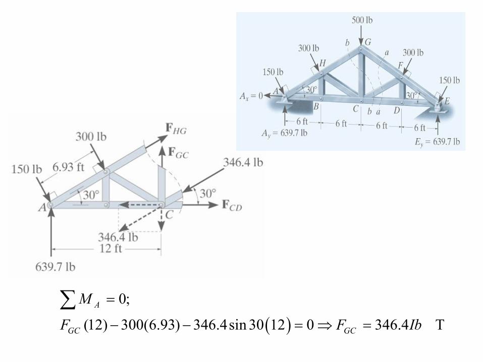
Example 4Solve the CF & GC members in the truss

C 4.3460)93.6(300)12(30sin
;0
IbFF
M
CFCF
E
0;
(12) 300(6.93) 346.4sin 30 12 0 346.4 T
A
GC GC
M
F F Ib

Determine the force in members GJ and CO of
the roof truss shown.
Example 5

Example 5
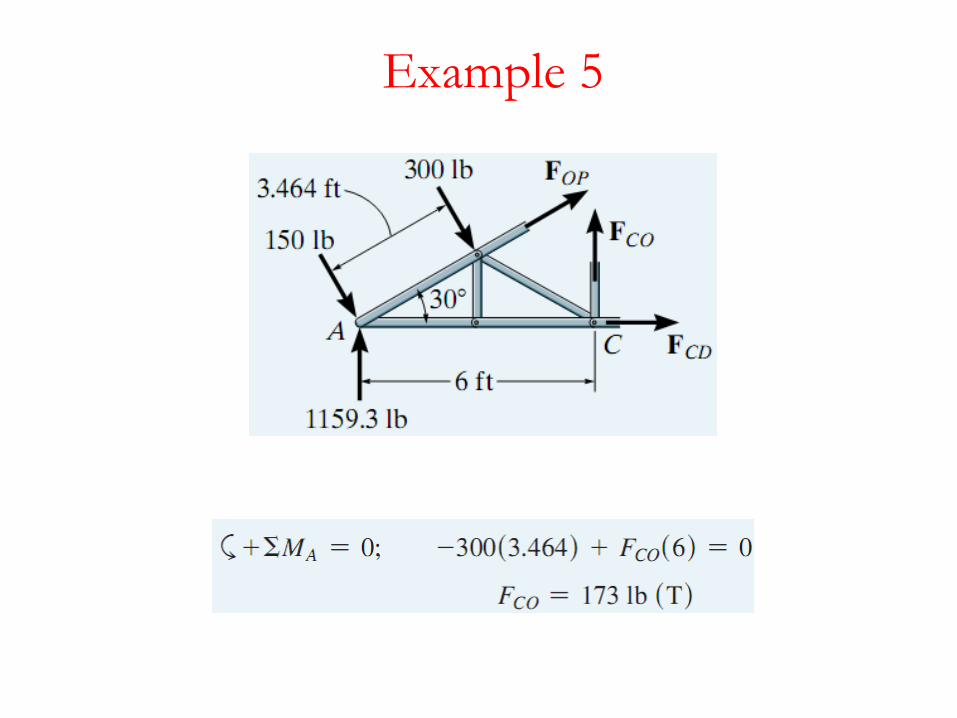
Example 5

Example 6Solve the GF & GD members in the truss

C 8.10)6(2)3(7)6(3.56sin0
C 83.70)3(7)3(6.26cos0
kNFFM
kNFFM
GFGDo
GFGFD

Example 7Solve the ED & EB members in the truss


Example 8Solve the BC & MC members in the K-truss

T 21750)20()15(29000 IbFFM BCBCL
TIbFF MBy 12000 BJoint At
TIbFFF MLMLy 29001200120029000
part cutting totalFor the

TIbF
CIbF
FFF
FFF
MC
MK
MKMCy
MKMCx
1532
1532
0120029000
00
MJoint At
13
2
13
2
13
3
13
3

Problem 2Solve All members

Problem 3Solve All members

Problem 4Solve members CH , CI

Example 1 Compound TrussSolve the truss

C 46.30)60sin4()2(4)4(50 kNFFM HGHGC

F
& FF
& FF
& FF
& FF
JC
BJBC
IBIJ
HJHI
AIAB
JJoint
BJoint
IJoint
HJoint
AJoint

Example 2 Compound Truss


Example 3 Compound TrussSolve the truss

F
& FF
EB
ABAE
BJoint
AJoint
AGAF
AE
& FF
F
AJoint
SolveAfter

Complex Truss
iii xsSS '
Force in members
?
0'
x
xsSS ECECEC

1
1
Complex Trusses
+=
X x
S´EC + x sEC = 0
x =S´EC
sEC
P
A
B
C
DF
Er + b = 2j,
3 9 2(6)
•Determinate
•Stable
F´ECP
A
B
C
DF
E
= FAD
SAD
sEC
A
B
C
DF
E
Si = S´i + x si

Member
AB
AC
AF
FE
BE
ED
FC
EC
'iS is ixsiS
iii xsSS '
?
0'
x
xsSS ECECEC

Example 1 Complex Truss


Example 2


P
b + r < 3j
b + r = 3j
Statically indeterminate -Check stability
• Determinacy and Stability
Space Truss
Unstable truss
b + r > 3j
Statically determinate -Check stability

•x, y, z, Force Components
Space Truss
222 zyxl
)(l
xFFx
)(l
yFFy
)(l
zFFz
222
zyx FFFF

x
y
z
y
z
x
y
z
x
z
x
y
x
y
z
Fy
Fz
Fz
Fx
Fx
Fz
Fy
short link
y
x
z
roller
z
x
yslotted roller
constrained
in a cylinder
y
z
x ball-and -socket
Support Reactions

Zero Force Member1- If all but one of the members connected to a joint lie on the
same plane, and provided no external load act on the joint, then
the member not lying in the plane of the other members must
subjected to zero force.
SFz = 0 , FD = 0

Zero Force Member2- If it has been determined that all but two of several members
connected at a joint support zero force, then the two remaining
members must also support zero force, provided they don’t lie a
long the same line and no external load act on the joint.
SFz = 0 , FB = 0
SFy = 0 , FD = 0
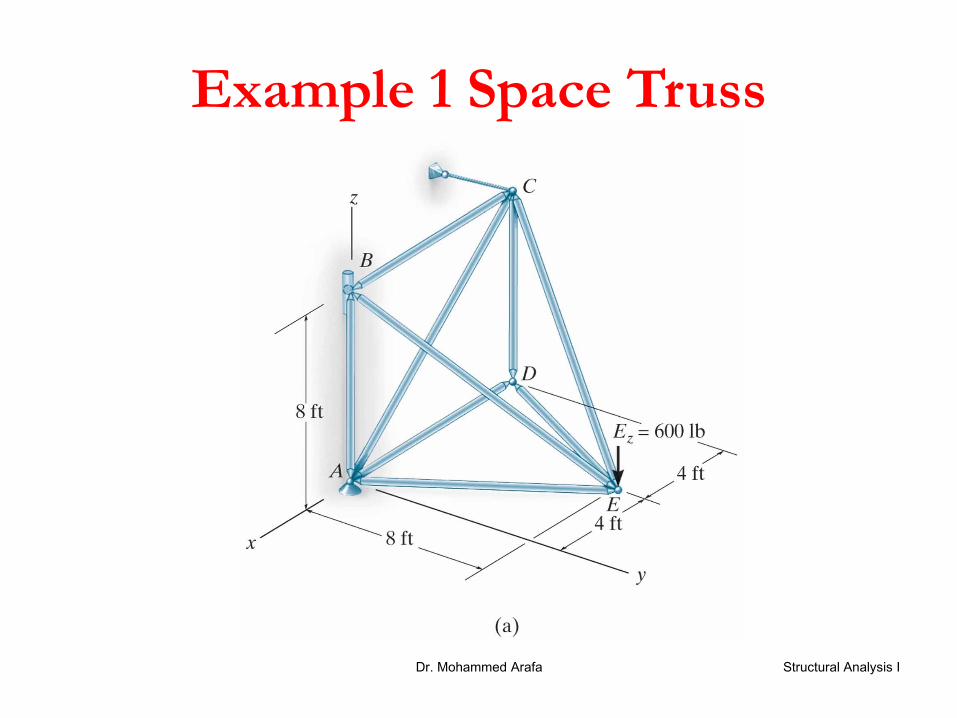
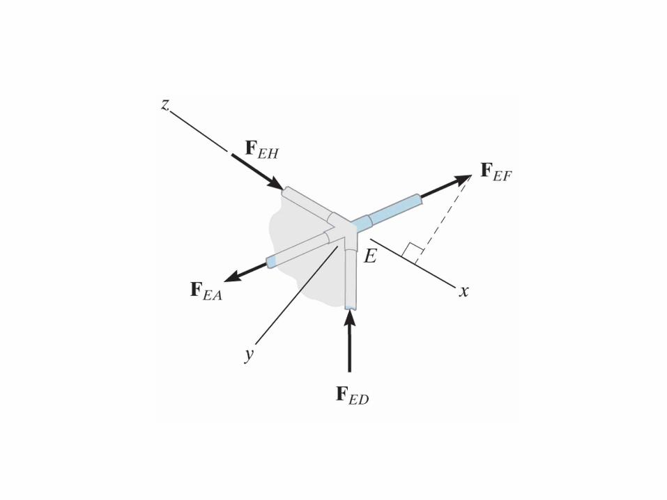
Example 1 Space Truss
Structural Analysis IDr. Mohammed Arafa


Example 2 Space Truss


Copyright © 2009 Pearson Prentice Hall Inc.