Truss Works
23
4/2/14 Trussworks web.mit.edu/emech/dontindex-build/java/trussworks/html/intro.html#Tutorial 1/23 1. Introduction 2. Demo of a sample problem Problem Statement Set Units Build Model Compute Save structure 3. Functions Available Fi l e New Open Overlay Save Download from Server Overlay from Server Save to Server New StructureXML Edit StructureXML View StructureXML Exit Graphics Pan Zoom Grid Scale View Node Numbers Ortho Snap to Grid 1. Introduction Trussworks allows users to easily create and analyze 3D Structures using the Direct Stiffness Method. It models truss structures that can carry axial loads loads. The click and drag interface lets you input two-dimensional structures, but the program can take in and perform calculations for three-dimensional structures as well using a text based XML input (see Section 4). Also included is a database of steel cross-sections and their corresponding geometric properties developed by a colleague and adapted for the programs, as well as material properties of the most commonly used engineering materials. The program is intended to be free to use, the primary target audience being undergraduate engineering students and faculty. The program, and source code, as well as the documentation, can all be downloaded free of cost. The authors' intend this to be an "open source" product, available for modification and expansion to suit any user's needs. While there is no limit to the number of nodes and members that might be modeled, it is not intended to function as industrial strength programs for structural engineering professionals - but it may be of use to the latter in preliminary design. Trussworks can be run both as an application on a users local machine, or as an applet on any web-browser. Back to Top 2. Demo of a sample problem Problem Statement Using Trussworks, model the structure shown in Figure 2.1 . All members are made of carbon steel, and use the W130x24 cross-section. Report the deflections at node 1, the reactions and node 0, and the member forces in member 0-1.
-
Upload
robsten-edbells -
Category
Documents
-
view
230 -
download
1
Transcript of Truss Works
4/2/14 Trussworks
web.mit.edu/emech/dontindex-build/java/trussworks/html/intro.html#Tutorial 1/23
1. Introduction
2. Demo of asampleproblem
Problem
Statement
Set Units
Build Model
Compute
Save structure
3. FunctionsAvailable
File
New
Open
Overlay
Save
Download
from Server
Overlay from
Server
Save to Server
New
StructureXML
Edit
StructureXML
View
StructureXML
Exit
Graphics
Pan
Zoom
Grid
Scale
View Node
Numbers
Ortho
Snap to Grid
1. Introduction
Trussworks allows users to easily create and analyze 3D Structures using the DirectStiffness Method. It models truss structures that can carry axial loads loads. The click
and drag interface lets you input two-dimensional structures, but the program can take in
and perform calculations for three-dimensional structures as well using a text based
XML input (see Section 4). Also included is a database of steel cross-sections and
their corresponding geometric properties developed by a colleague and adapted for the
programs, as well as material properties of the most commonly used engineering
materials.
The program is intended to be free to use, the primary target audience beingundergraduate engineering students and faculty. The program, and source code, as well
as the documentation, can all be downloaded free of cost. The authors' intend this to bean "open source" product, available for modification and expansion to suit any user'sneeds. While there is no limit to the number of nodes and members that might be
modeled, it is not intended to function as industrial strength programs for structural
engineering professionals - but it may be of use to the latter in preliminary design.
Trussworks can be run both as an application on a users local machine, or as an applet
on any web-browser.
Back to Top
2. Demo of a sample problem
Problem Statement
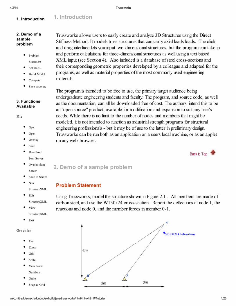
Using Trussworks, model the structure shown in Figure 2.1 . All members are made of
carbon steel, and use the W130x24 cross-section. Report the deflections at node 1, the
reactions and node 0, and the member forces in member 0-1.
4/2/14 Trussworks
web.mit.edu/emech/dontindex-build/java/trussworks/html/intro.html#Tutorial 2/23
Function
Add Member
Enter Member
Properties
Constrain
Node
Load Node
Edit Node
Coordinates
Remove
Member
Remove
Constraints
Unload Node
Compute
View Stiffness
Matrix
Member
Forces
Reactions
View
Displaced
Structure
Text Output
4.StructureXML
Benefits of
using XML
About
StructureXML
Figure 2.1 - Sample truss to be modeled
Back to Top
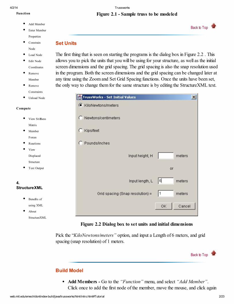
Set Units
The first thing that is seen on starting the programs is the dialog box in Figure 2.2 . This
allows you to pick the units that you will be using for your structure, as well as the initial
screen dimensions and the grid spacing. The grid spacing is also the snap resolution used
in the program. Both the screen dimensions and the grid spacing can be changed later atany time using the Zoom and Set Grid Spacing functions. Once the units have been set,
the only way to change them for the same structure is by editing the StructureXML text.
Figure 2.2 Dialog box to set units and initial dimensions
Pick the “KiloNewtons/meters” option, and input a Length of 6 meters, and gridspacing (snap resolution) of 1 meters.
Back to Top
Build Model
Add Members - Go to the “Function” menu, and select “Add Member”. Click once to add the first node of the member, move the mouse, and click again
4/2/14 Trussworks
web.mit.edu/emech/dontindex-build/java/trussworks/html/intro.html#Tutorial 3/23
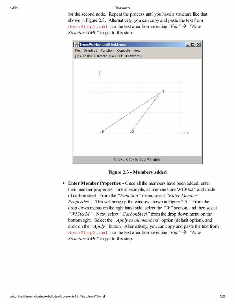
for the second node. Repeat the process until you have a structure like that
shown in Figure 2.3. Alternatively, you can copy and paste the text fromdemoStep1.xml into the text area from selecting "File" à "New
StructureXML" to get to this step.
Figure 2.3 - Members added
Enter Member Properties - Once all the members have been added, enter
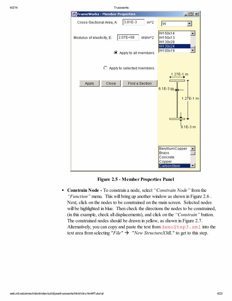
their member properties. In this example, all members are W130x24 and madeof carbon steel. From the “Function” menu, select “Enter Member
Properties”. This will bring up the window shown in Figure 2.5 . From thedrop down menus on the right hand side, select the “W” section, and then select
“W130x24”. Next, select “CarbonSteel” from the drop down menu on thebottom right. Select the “Apply to all members” option (default option), and
click on the “Apply” button. Alternatively, you can copy and paste the text from
demoStep2.xml into the text area from selecting "File" à "NewStructureXML" to get to this step.
4/2/14 Trussworks
web.mit.edu/emech/dontindex-build/java/trussworks/html/intro.html#Tutorial 4/23
Figure 2.5 - Member Properties Panel
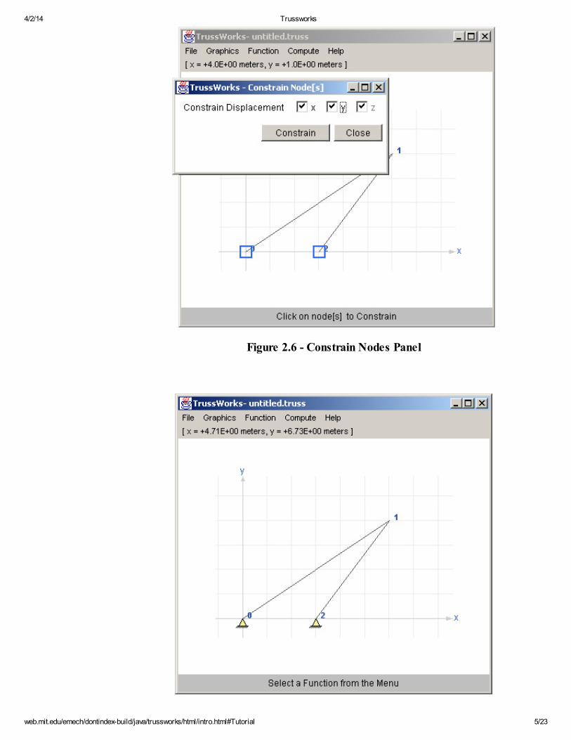
Constrain Node - To constrain a node, select “Constrain Node” from the“Function” menu. This will bring up another window as shown in Figure 2.6 .
Next, click on the nodes to be constrained on the main screen. Selected nodes
will be highlighted in blue. Then check the directions the nodes to be constrained,
(in this example, check all displacements), and click on the “Constrain” button. The constrained nodes should be drawn in yellow, as shown in Figure 2.7.
Alternatively, you can copy and paste the text from demoStep3.xml into the
text area from selecting "File" à "New StructureXML" to get to this step.
4/2/14 Trussworks
web.mit.edu/emech/dontindex-build/java/trussworks/html/intro.html#Tutorial 5/23
Figure 2.6 - Constrain Nodes Panel
4/2/14 Trussworks
web.mit.edu/emech/dontindex-build/java/trussworks/html/intro.html#Tutorial 6/23
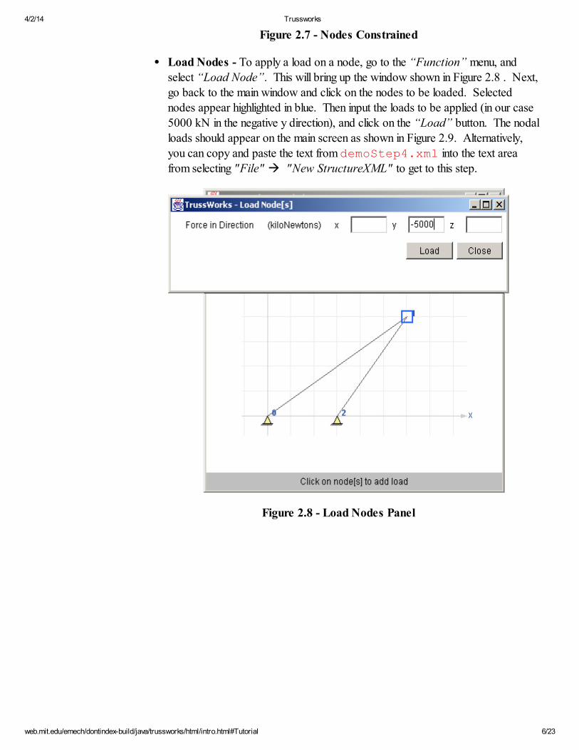
Figure 2.7 - Nodes Constrained
Load Nodes - To apply a load on a node, go to the “Function” menu, andselect “Load Node”. This will bring up the window shown in Figure 2.8 . Next,
go back to the main window and click on the nodes to be loaded. Selected
nodes appear highlighted in blue. Then input the loads to be applied (in our case
5000 kN in the negative y direction), and click on the “Load” button. The nodalloads should appear on the main screen as shown in Figure 2.9. Alternatively,
you can copy and paste the text from demoStep4.xml into the text area
from selecting "File" à "New StructureXML" to get to this step.
Figure 2.8 - Load Nodes Panel
4/2/14 Trussworks
web.mit.edu/emech/dontindex-build/java/trussworks/html/intro.html#Tutorial 7/23
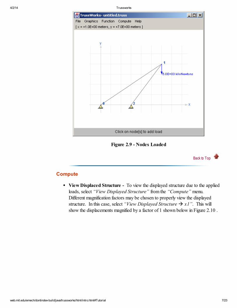
Figure 2.9 - Nodes Loaded
Back to Top
Compute
View Displaced Structure - To view the displayed structure due to the applied
loads, select “View Displayed Structure” from the “Compute” menu.
Different magnification factors may be chosen to properly view the displayed
structure. In this case, select “View Displayed Structure à x1”. This willshow the displacements magnified by a factor of 1 shown below in Figure 2.10 .
4/2/14 Trussworks
web.mit.edu/emech/dontindex-build/java/trussworks/html/intro.html#Tutorial 8/23
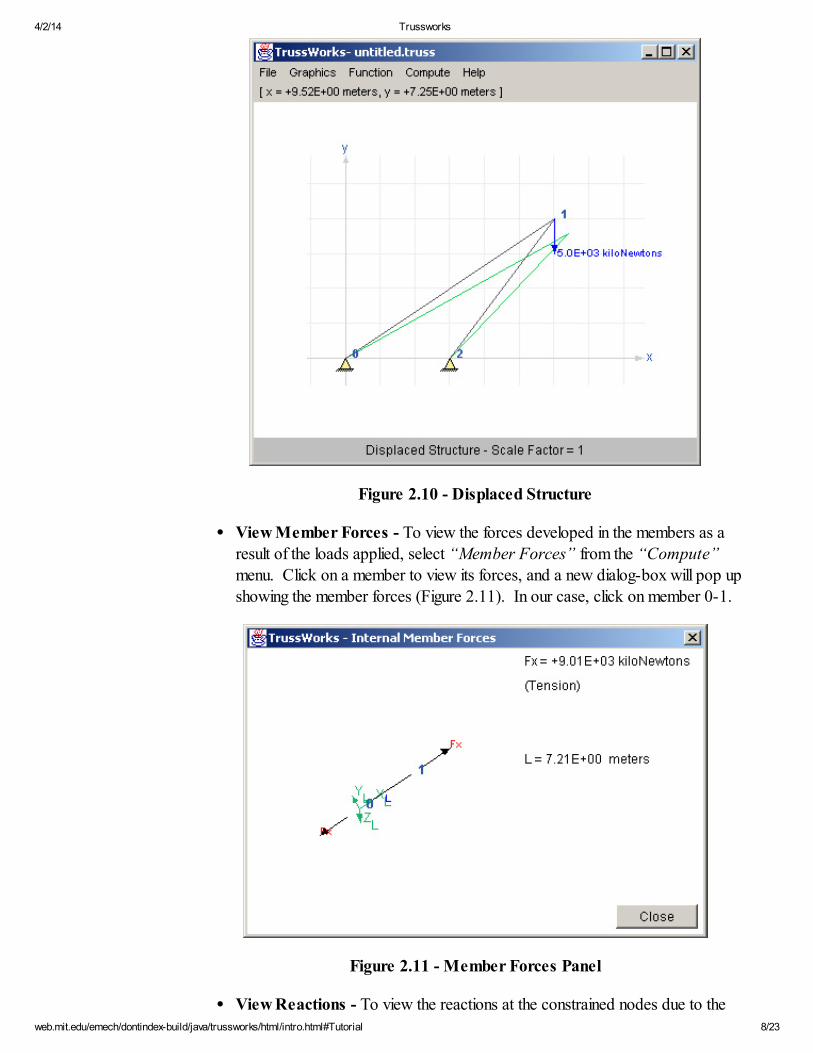
Figure 2.10 - Displaced Structure
View Member Forces - To view the forces developed in the members as a
result of the loads applied, select “Member Forces” from the “Compute”
menu. Click on a member to view its forces, and a new dialog-box will pop up
showing the member forces (Figure 2.11). In our case, click on member 0-1.
Figure 2.11 - Member Forces Panel
View Reactions - To view the reactions at the constrained nodes due to the
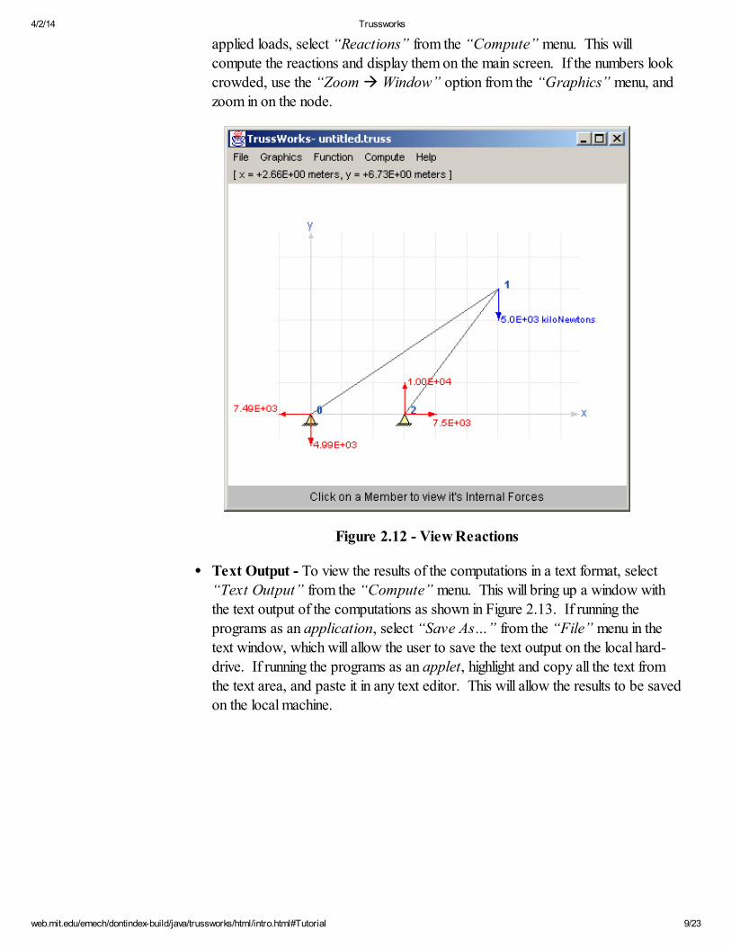
4/2/14 Trussworks
web.mit.edu/emech/dontindex-build/java/trussworks/html/intro.html#Tutorial 9/23
applied loads, select “Reactions” from the “Compute” menu. This will
compute the reactions and display them on the main screen. If the numbers look
crowded, use the “Zoom à Window” option from the “Graphics” menu, and
zoom in on the node.
Figure 2.12 - View Reactions
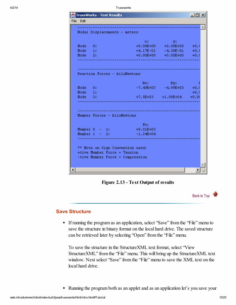
Text Output - To view the results of the computations in a text format, select
“Text Output” from the “Compute” menu. This will bring up a window with
the text output of the computations as shown in Figure 2.13. If running the
programs as an application, select “Save As…” from the “File” menu in the
text window, which will allow the user to save the text output on the local hard-
drive. If running the programs as an applet, highlight and copy all the text fromthe text area, and paste it in any text editor. This will allow the results to be saved
on the local machine.
4/2/14 Trussworks
web.mit.edu/emech/dontindex-build/java/trussworks/html/intro.html#Tutorial 10/23
Figure 2.13 - Text Output of results
Back to Top
Save Structure
If running the program as an application, select “Save” from the “File” menu to
save the structure in binary format on the local hard drive. The saved structure
can be retrieved later by selecting “Open” from the “File” menu.
To save the structure in the StructureXML text format, select “View
StructureXML” from the “File” menu. This will bring up the StructureXML text
window. Next select “Save” from the “File” menu to save the XML text on the
local hard drive.
Running the program both as an applet and as an application let’s you save your
4/2/14 Trussworks
web.mit.edu/emech/dontindex-build/java/trussworks/html/intro.html#Tutorial 11/23
structure to the server over the Internet. Select “Save to Server” from the “File”
menu. This will upload the structure in binary format to the server running the
applet. The file can later be retrieved by selecting “Download from Server”.
To save the structure in the StructureXML format when running as an applet,
select “View StructureXML” from the “File” menu. This will bring up the
StructureXML text window. Next, select “Select All”, followed by “Copy” from
the “Edit” menu and paste the copied text to any text editor and save it on thelocal hard drive. To retrieve a structure from the XML later, open the XML text
using any text editor, copy the StructureXML, and paste it on the text window
from the “New StructureXML” option in the “File” menu and hit the “OK”
button.
Back to Top
3. Functions Available
The functionalities available in Trussworks can be broken into four main groups, which
are simply the menu items that are present in the program.
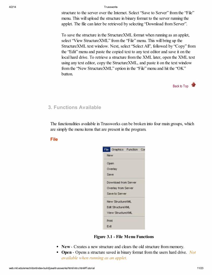
File
Figure 3.1 - File Menu Functions
New - Creates a new structure and clears the old structure from memory.
Open - Opens a structure saved in binary format from the users hard drive. Not
available when running as an applet.
4/2/14 Trussworks
web.mit.edu/emech/dontindex-build/java/trussworks/html/intro.html#Tutorial 12/23
Overlay - Overlays another structure saved in binary format from the users hard
drive onto the existing structure. The program increments the node numbers of the
second structure with the number of nodes present in the first structure. Not
available when running as an applet.
This would allow, for example, different users to work on different parts of a
structure. Once the parts have been created and saved, they can all be overlaid to
form the whole structure.Save - Saves structure in binary format on users hard drive. Not available
when running as an applet.Download from Server - Downloads structure saved in binary format in a
server over the Internet using TCP. Applets can only download structuresfrom a server that has the same host name as the web server from which itoriginated.
Overlay from Server - Overlays another structure saved in binary format bydownloading the second structure from a server over the Internet using TCP.
Applets can only overlay structures from a server that has the same hostname as the web server from which it originated.
Save to Server - Saves structure in binary format to a server over the Internetusing TCP. Applets can only save structures to a server that has the samehost name as the web server from which it originated.
New StructureXML - Starts a new StructureXML document (see Section 4). If running the programs as an application, then File à Open opens a dialog box
that lets the user open a text (XML) document from their hard drive. Usersrunning the program as an applet can copy a StructureXML text from a
local file, and paste it on the textarea.Edit StructureXML - Lets the user edit their structure as a text (XML) file.View StructureXML - Lets the user view their structure in the StructureXML
format. If running as an application, File à Save lets the user save thestructureXML document in their hard drive. Applet users who want to save the
StructureXML text must highlight all the text in the textarea, copy it, andthen paste it on a text editor to save it on their hard drive.
Exit - Closes the program and clears the structure from memory.
Back to Top
Graphics
4/2/14 Trussworks
web.mit.edu/emech/dontindex-build/java/trussworks/html/intro.html#Tutorial 13/23
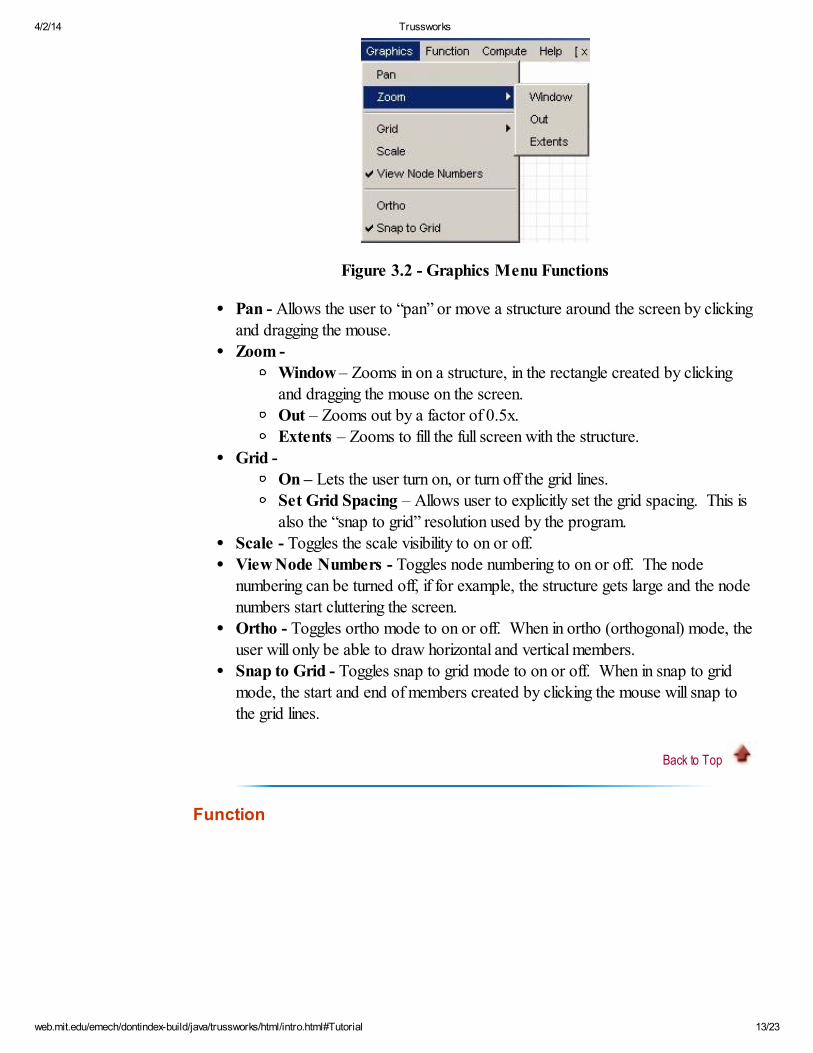
Figure 3.2 - Graphics Menu Functions
Pan - Allows the user to “pan” or move a structure around the screen by clicking
and dragging the mouse.Zoom -
Window – Zooms in on a structure, in the rectangle created by clickingand dragging the mouse on the screen.
Out – Zooms out by a factor of 0.5x. Extents – Zooms to fill the full screen with the structure.
Grid -
On – Lets the user turn on, or turn off the grid lines.Set Grid Spacing – Allows user to explicitly set the grid spacing. This is
also the “snap to grid” resolution used by the program.Scale - Toggles the scale visibility to on or off.
View Node Numbers - Toggles node numbering to on or off. The nodenumbering can be turned off, if for example, the structure gets large and the nodenumbers start cluttering the screen.
Ortho - Toggles ortho mode to on or off. When in ortho (orthogonal) mode, theuser will only be able to draw horizontal and vertical members.
Snap to Grid - Toggles snap to grid mode to on or off. When in snap to gridmode, the start and end of members created by clicking the mouse will snap to
the grid lines.
Back to Top
Function
4/2/14 Trussworks
web.mit.edu/emech/dontindex-build/java/trussworks/html/intro.html#Tutorial 14/23
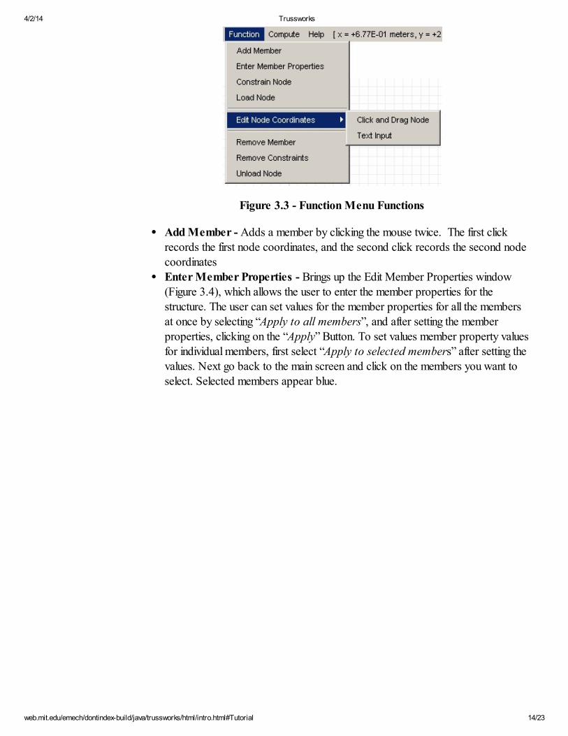
Figure 3.3 - Function Menu Functions
Add Member - Adds a member by clicking the mouse twice. The first clickrecords the first node coordinates, and the second click records the second nodecoordinates
Enter Member Properties - Brings up the Edit Member Properties window(Figure 3.4), which allows the user to enter the member properties for the
structure. The user can set values for the member properties for all the membersat once by selecting “Apply to all members”, and after setting the member
properties, clicking on the “Apply” Button. To set values member property valuesfor individual members, first select “Apply to selected members” after setting thevalues. Next go back to the main screen and click on the members you want to
select. Selected members appear blue.
4/2/14 Trussworks
web.mit.edu/emech/dontindex-build/java/trussworks/html/intro.html#Tutorial 15/23
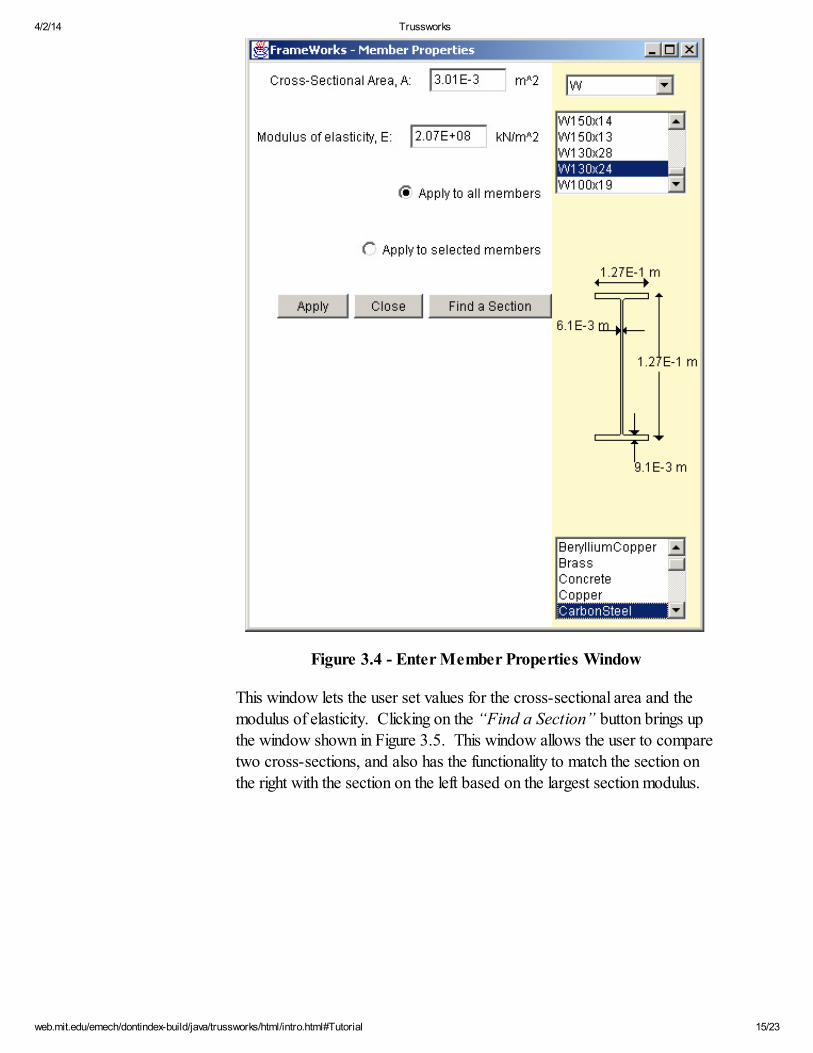
Figure 3.4 - Enter Member Properties Window
This window lets the user set values for the cross-sectional area and themodulus of elasticity. Clicking on the “Find a Section” button brings up
the window shown in Figure 3.5. This window allows the user to comparetwo cross-sections, and also has the functionality to match the section onthe right with the section on the left based on the largest section modulus.
4/2/14 Trussworks
web.mit.edu/emech/dontindex-build/java/trussworks/html/intro.html#Tutorial 16/23
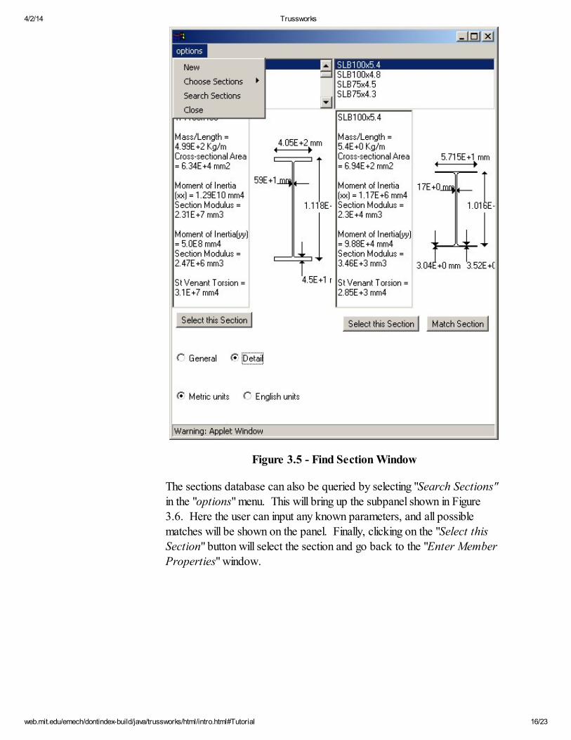
Figure 3.5 - Find Section Window
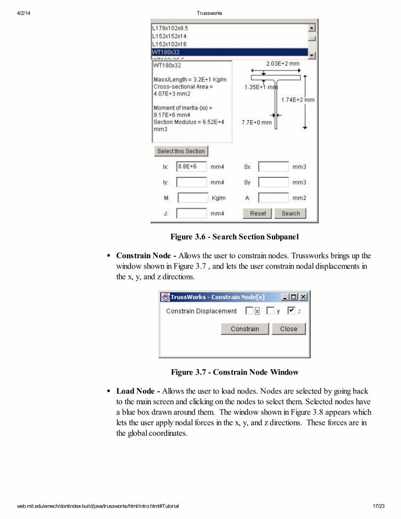
The sections database can also be queried by selecting "Search Sections"in the "options" menu. This will bring up the subpanel shown in Figure3.6. Here the user can input any known parameters, and all possible
matches will be shown on the panel. Finally, clicking on the "Select thisSection" button will select the section and go back to the "Enter Member
Properties" window.
4/2/14 Trussworks
web.mit.edu/emech/dontindex-build/java/trussworks/html/intro.html#Tutorial 17/23
Figure 3.6 - Search Section Subpanel
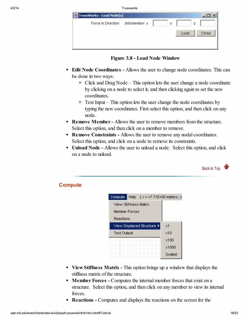
Constrain Node - Allows the user to constrain nodes. Trussworks brings up the
window shown in Figure 3.7 , and lets the user constrain nodal displacements inthe x, y, and z directions.
Figure 3.7 - Constrain Node Window
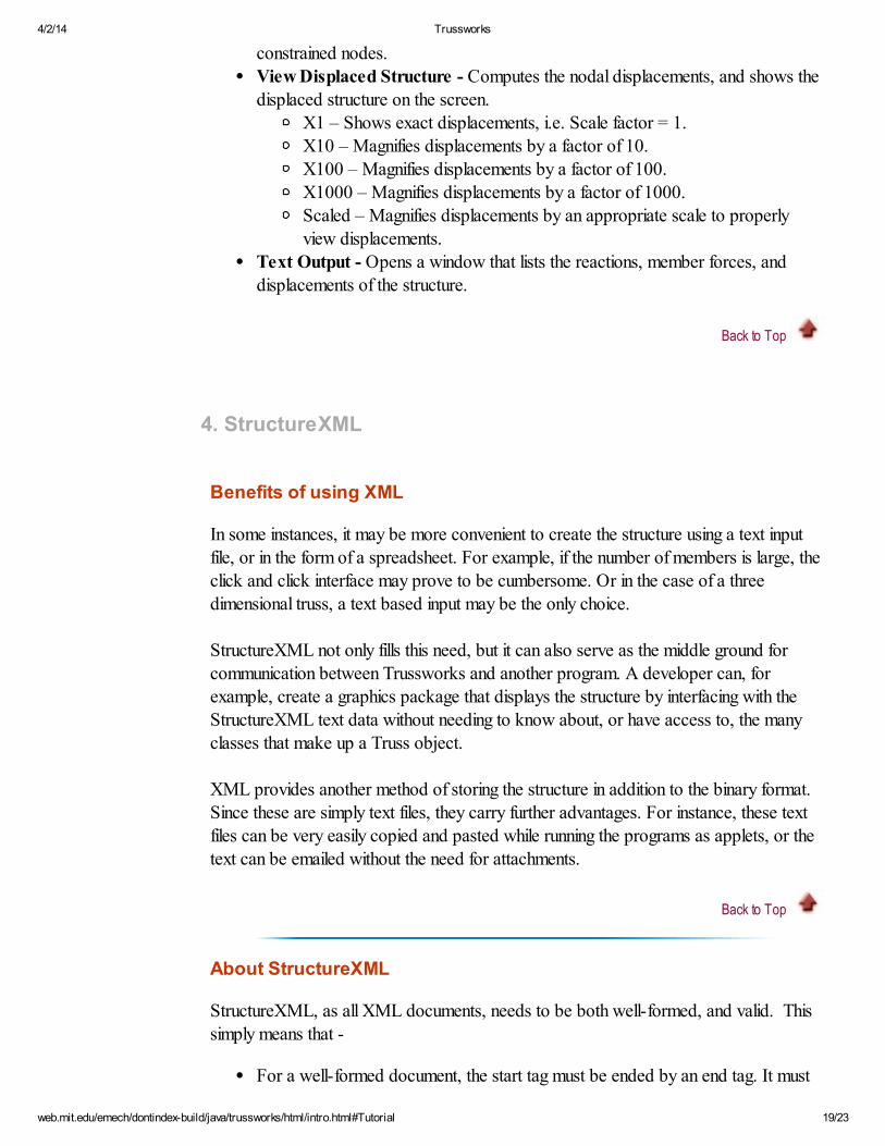
Load Node - Allows the user to load nodes. Nodes are selected by going backto the main screen and clicking on the nodes to select them. Selected nodes have
a blue box drawn around them. The window shown in Figure 3.8 appears whichlets the user apply nodal forces in the x, y, and z directions. These forces are inthe global coordinates.
4/2/14 Trussworks
web.mit.edu/emech/dontindex-build/java/trussworks/html/intro.html#Tutorial 18/23
Figure 3.8 - Load Node Window
Edit Node Coordinates - Allows the user to change node coordinates. This canbe done in two ways:
Click and Drag Node – This option lets the user change a node coordinateby clicking on a node to select it, and then clicking again to set the newcoordinates.
Text Input – This option lets the user change the node coordinates bytyping the new coordinates. First select this option, and then click on any
node.Remove Member - Allows the user to remove members from the structure.
Select this option, and then click on a member to remove.Remove Constraints - Allows the user to remove any nodal coordinates. Select this option, and click on a node to remove its constraints.
Unload Node - Allows the user to unload a node. Select this option, and clickon a node to unload.
Back to Top
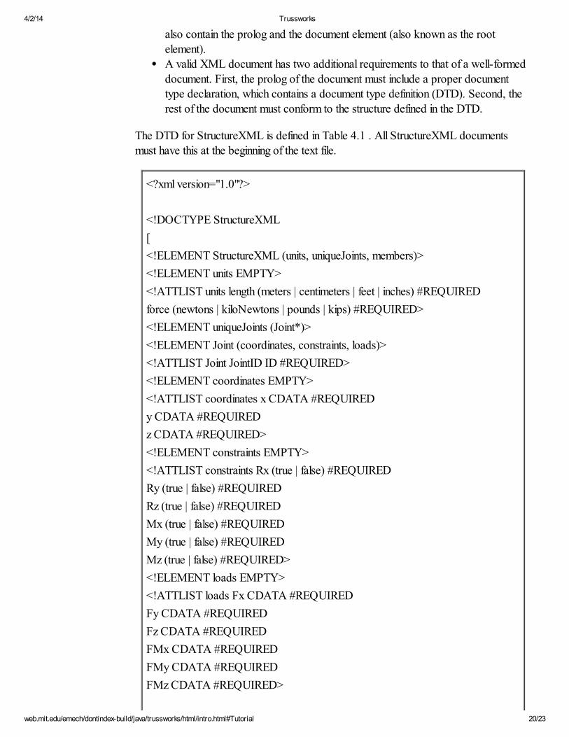
Compute
View Stiffness Matrix - This option brings up a window that displays thestiffness matrix of the structure.
Member Forces - Computes the internal member forces that exist on astructure. Select this option, and then click on any member to view its internalforces.
Reactions - Computes and displays the reactions on the screen for the
4/2/14 Trussworks
web.mit.edu/emech/dontindex-build/java/trussworks/html/intro.html#Tutorial 19/23
constrained nodes.View Displaced Structure - Computes the nodal displacements, and shows the
displaced structure on the screen. X1 – Shows exact displacements, i.e. Scale factor = 1. X10 – Magnifies displacements by a factor of 10.
X100 – Magnifies displacements by a factor of 100. X1000 – Magnifies displacements by a factor of 1000.
Scaled – Magnifies displacements by an appropriate scale to properlyview displacements.
Text Output - Opens a window that lists the reactions, member forces, anddisplacements of the structure.
Back to Top
4. StructureXML
Benefits of using XML
In some instances, it may be more convenient to create the structure using a text input
file, or in the form of a spreadsheet. For example, if the number of members is large, theclick and click interface may prove to be cumbersome. Or in the case of a threedimensional truss, a text based input may be the only choice.
StructureXML not only fills this need, but it can also serve as the middle ground for
communication between Trussworks and another program. A developer can, forexample, create a graphics package that displays the structure by interfacing with the
StructureXML text data without needing to know about, or have access to, the manyclasses that make up a Truss object.
XML provides another method of storing the structure in addition to the binary format.Since these are simply text files, they carry further advantages. For instance, these text
files can be very easily copied and pasted while running the programs as applets, or thetext can be emailed without the need for attachments.
Back to Top
About StructureXML
StructureXML, as all XML documents, needs to be both well-formed, and valid. This
simply means that -
For a well-formed document, the start tag must be ended by an end tag. It must
4/2/14 Trussworks
web.mit.edu/emech/dontindex-build/java/trussworks/html/intro.html#Tutorial 20/23
also contain the prolog and the document element (also known as the root
element).A valid XML document has two additional requirements to that of a well-formeddocument. First, the prolog of the document must include a proper document
type declaration, which contains a document type definition (DTD). Second, therest of the document must conform to the structure defined in the DTD.
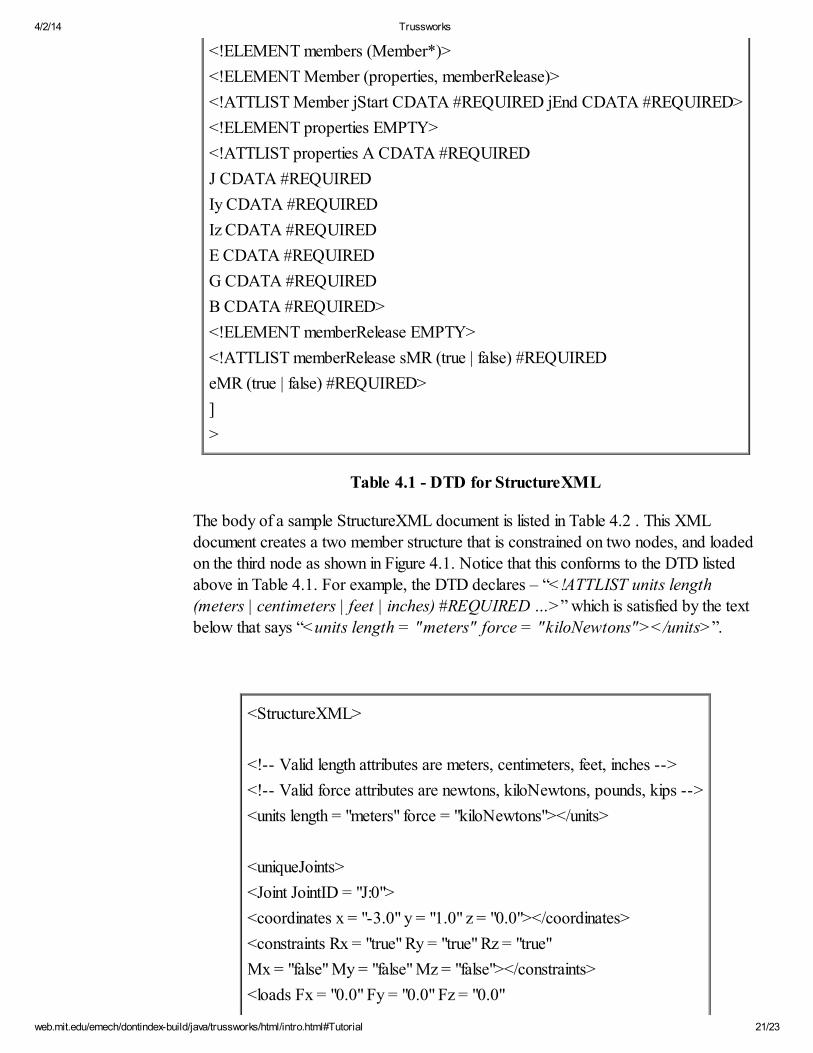
The DTD for StructureXML is defined in Table 4.1 . All StructureXML documentsmust have this at the beginning of the text file.
<?xml version="1.0"?>
<!DOCTYPE StructureXML
[
<!ELEMENT StructureXML (units, uniqueJoints, members)>
<!ELEMENT units EMPTY>
<!ATTLIST units length (meters | centimeters | feet | inches) #REQUIRED
force (newtons | kiloNewtons | pounds | kips) #REQUIRED>
<!ELEMENT uniqueJoints (Joint*)>
<!ELEMENT Joint (coordinates, constraints, loads)>
<!ATTLIST Joint JointID ID #REQUIRED>
<!ELEMENT coordinates EMPTY>
<!ATTLIST coordinates x CDATA #REQUIRED
y CDATA #REQUIRED
z CDATA #REQUIRED>
<!ELEMENT constraints EMPTY>
<!ATTLIST constraints Rx (true | false) #REQUIRED
Ry (true | false) #REQUIRED
Rz (true | false) #REQUIRED
Mx (true | false) #REQUIRED
My (true | false) #REQUIRED
Mz (true | false) #REQUIRED>
<!ELEMENT loads EMPTY>
<!ATTLIST loads Fx CDATA #REQUIRED
Fy CDATA #REQUIRED
Fz CDATA #REQUIRED
FMx CDATA #REQUIRED
FMy CDATA #REQUIRED
FMz CDATA #REQUIRED>
4/2/14 Trussworks
web.mit.edu/emech/dontindex-build/java/trussworks/html/intro.html#Tutorial 21/23
<!ELEMENT members (Member*)>
<!ELEMENT Member (properties, memberRelease)>
<!ATTLIST Member jStart CDATA #REQUIRED jEnd CDATA #REQUIRED>
<!ELEMENT properties EMPTY>
<!ATTLIST properties A CDATA #REQUIRED
J CDATA #REQUIRED
Iy CDATA #REQUIRED
Iz CDATA #REQUIRED
E CDATA #REQUIRED
G CDATA #REQUIRED
B CDATA #REQUIRED>
<!ELEMENT memberRelease EMPTY>
<!ATTLIST memberRelease sMR (true | false) #REQUIRED
eMR (true | false) #REQUIRED>
]
>
Table 4.1 - DTD for StructureXML
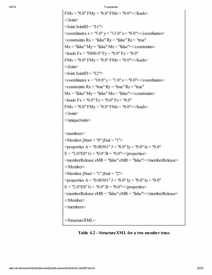
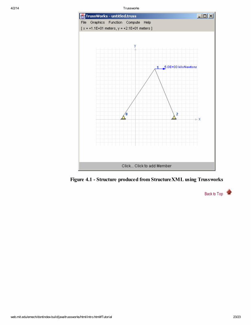
The body of a sample StructureXML document is listed in Table 4.2 . This XML
document creates a two member structure that is constrained on two nodes, and loadedon the third node as shown in Figure 4.1. Notice that this conforms to the DTD listed
above in Table 4.1. For example, the DTD declares – “<!ATTLIST units length(meters | centimeters | feet | inches) #REQUIRED …>” which is satisfied by the text
below that says “<units length = "meters" force = "kiloNewtons"></units>”.
<StructureXML>
<!-- Valid length attributes are meters, centimeters, feet, inches -->
<!-- Valid force attributes are newtons, kiloNewtons, pounds, kips -->
<units length = "meters" force = "kiloNewtons"></units>
<uniqueJoints>
<Joint JointID = "J:0">
<coordinates x = "-3.0" y = "1.0" z = "0.0"></coordinates>
<constraints Rx = "true" Ry = "true" Rz = "true"
Mx = "false" My = "false" Mz = "false"></constraints>
<loads Fx = "0.0" Fy = "0.0" Fz = "0.0"
4/2/14 Trussworks
web.mit.edu/emech/dontindex-build/java/trussworks/html/intro.html#Tutorial 22/23
FMx = "0.0" FMy = "0.0" FMz = "0.0"></loads>
</Joint>
<Joint JointID = "J:1">
<coordinates x = "5.0" y = "13.0" z = "0.0"></coordinates>
<constraints Rx = "false" Ry = "false" Rz = "true"
Mx = "false" My = "false" Mz = "false"></constraints>
<loads Fx = "5000.0" Fy = "0.0" Fz = "0.0"
FMx = "0.0" FMy = "0.0" FMz = "0.0"></loads>
</Joint>
<Joint JointID = "J:2">
<coordinates x = "10.0" y = "1.0" z = "0.0"></coordinates>
<constraints Rx = "true" Ry = "true" Rz = "true"
Mx = "false" My = "false" Mz = "false"></constraints>
<loads Fx = "0.0" Fy = "0.0" Fz = "0.0"
FMx = "0.0" FMy = "0.0" FMz = "0.0"></loads>
</Joint>
</uniqueJoints>
<members>
<Member jStart = "0" jEnd = "1">
<properties A = "0.00301" J = "0.0" Iy = "0.0" Iz = "0.0"
E = "2.07E8" G = "0.0" B = "0.0"></properties>
<memberRelease sMR = "false" eMR = "false"></memberRelease>
</Member>
<Member jStart = "1" jEnd = "2">
<properties A = "0.00301" J = "0.0" Iy = "0.0" Iz = "0.0"
E = "2.07E8" G = "0.0" B = "0.0"></properties>
<memberRelease sMR = "false" eMR = "false"></memberRelease>
</Member>
</members>
</StructureXML>
Table 4.2 - StructureXML for a two member truss
4/2/14 Trussworks
web.mit.edu/emech/dontindex-build/java/trussworks/html/intro.html#Tutorial 23/23
Figure 4.1 - Structure produced from StructureXML using Trussworks
Back to Top