TruSine 4500 - Inverter Charger, Power Inverter, … · TruSine 4500 4.5 kW Inverter/Charger System...
30
Owner’s Manual TruSine 4.5 kW Inverter Page 1 Owner’s Manual TruSine 4500 4.5 kW Inverter/Charger System 4.5 kW Power Inverter Models TSC24-4500 TSC24-4500D Owner’s Manual D98771 Rev B
Transcript of TruSine 4500 - Inverter Charger, Power Inverter, … · TruSine 4500 4.5 kW Inverter/Charger System...

Owner’s Manual
TruSine 4.5 kW Inverter Page 1 Owner’s Manual
TruSine 45004.5 kW Inverter/Charger System
4.5 kW Power Inverter
Models TSC24-4500 TSC24-4500D
Owner’s Manual D98771 Rev B

TruSine 4500
TruSine 4.5 kW Inverter Page 2 Owners Manual
Notes

Table of Contents
TruSine 4.5 kW Inverter Page 3 Owner’s Manual
Table of Contents
1 SYSTEM FEATURES AND SPECIFICATIONS.................................................................................... 4
1.1 GENERAL DESCRIPTION .................................................................................................................... 41.2 SYSTEM FEATURES ........................................................................................................................... 41.3 SPECIFICATIONS ............................................................................................................................... 6
2 DESCRIPTION OF OPERATION.......................................................................................................... 7
2.1 INVERTER ......................................................................................................................................... 72.2 BATTERY CHARGER .......................................................................................................................... 72.3 AUTOMATIC TRANSFER SWITCH WITH SOLAR MODE............................................................................ 92.4 GEN START .................................................................................................................................... 10
3 TSR-2 REMOTE CONTROL PANEL (OPTIONAL)............................................................................ 10
3.1 GENERAL DESCRIPTION .................................................................................................................. 103.2 ADJUSTABLE FACTORY SETPOINTS FOR THE TRUSINE 4500 ............................................................. 113.3 OPERATION .................................................................................................................................... 113.4 MENU MAP ..................................................................................................................................... 13
4 FRONT PANEL WIRING IDENTIFICATION ....................................................................................... 18
4.1 AC INPUT & OUTPUT WIRING .......................................................................................................... 184.2 DC (BATTERY) WIRING................................................................................................................... 184.3 SYSTEM ON INDICATOR .................................................................................................................. 184.4 BATTERY TEMPERATURE SENSOR PORT .......................................................................................... 184.5 V-NET PORT / TSR-2 REMOTE CONTROL PORT.............................................................................. 184.6 SERIAL INTERFACE PORT ................................................................................................................ 184.7 INVERTER OUTPUT CIRCUIT BREAKER ............................................................................................. 184.8 SYSTEM ON/OFF SWITCH .............................................................................................................. 194.9 REMOTE SIGNAL CONTACTS ............................................................................................................ 19
5 INSTALLATION................................................................................................................................... 19
5.1 BASIC GUIDELINES.......................................................................................................................... 195.2 DC WIRING .................................................................................................................................... 195.3 AC WIRING .................................................................................................................................... 215.4 TSR-2 TRUSINE REMOTE CONTROL PANEL INSTALLATION ............................................................... 225.5 SYSTEM START-UP AND TESTING ..................................................................................................... 22
6 GENERAL INFORMATION SECTION................................................................................................ 23
6.1 GENERIC INVERTER DESCRIPTION.................................................................................................... 236.2 INVERTER SIZING ............................................................................................................................ 236.3 DC POWER CONSUMPTION ............................................................................................................. 246.4 BATTERY TERMINOLOGY AND RATINGS ............................................................................................ 256.5 SIZING THE INVERTER BATTERY ....................................................................................................... 266.6 BATTERY AND CHARGING SYSTEM CONSIDERATIONS ........................................................................ 266.7 BATTERY CHARGING GUIDELINES .................................................................................................... 27
7 MAINTENANCE & TROUBLESHOOTING......................................................................................... 27
7.1 PREVENTATIVE MAINTENANCE ......................................................................................................... 27
8 WARRANTY ........................................................................................................................................ 29

System Features and Specifications
TruSine 4.5 kW Inverter Page 4 Owners Manual
Introduction
Thank you for purchasing a Vanner TruSine inverter system. We are confident that you will be satisfied with itsperformance and its many features. With proper installation and care, you can look forward to years of servicefrom this high performance product.
This document will describe the operation, technical specifications and installation procedures for the TruSineInverter/Charger System. If you require additional information please contact your dealer, or contact usdirectly at the location shown on the cover of this manual.
1 System Features and Specifications
1.1 General Description
The TruSine system consists of a 4500 watt DC to AC true sine wave inverter, a 100 amp 24 volt batterycharger, an automatic AC transfer switch, and a microprocessor based controller with data communicationscapability. A key feature of this system is the optional TSR-2 TruSine Remote Control Panel operator’sinterface which utilizes a high speed “data highway” to connect one or more TSR-2 units to the inverter.
INVERTER
CHARGER
MICROPROCESSORCO NTROLLER
AUTOMATICAC
TRANSFERSW ITCH
TRUSINE INVERTER /CHARGER SYSTEM
BATTERY
AC Output ToAC Loads
AC Input UtilityPow er Generator
TSR-2 TSR-2TSR-2 RemoteControl Panel
V-NET Data Bus
Figure 1 - System Diagram
1.2 System Features
• InverterThe inverter consists of two sine wave inverters built into one unit. A “low power“ high efficiency 70 wattinverter supplies power for the small loads. The “high power” 4,500 watt main inverter supplies powerwhen AC loads over 70 watts are applied. Designed for maximum efficiency this system conserves batterypower when only small loads are present. To further conserve battery power the Load Demand featureallows the inverter to ‘go to sleep’ if AC loads fall below a selected value. Load Demand may be disabled ifvery small AC loads must be operated.The inverter develops up to 4,500 watts of continuous power. Using TruSine® technology, a very highquality pure sine wave is produced. Total harmonic distortion (THD) is less than 2.0 percent.

System Features and Specificatiions
TruSine 4.5 kW Inverter Page 5 Owner’s Manual
• Battery Charger with Automatic Power ManagementA high efficiency 100 amp multi-stage battery charger allows fully automatic charging of flooded and gellead acid battery banks. The efficient 0.85PF, compared to typical 0.59PF on triac type chargers, allowsfull charger output from a 30 amp aux AC source. The system’s Bulk - Absorption - Float charge cyclequickly charges and maintains the charge on the battery bank. An Equalization charge cycle is providedfor flooded lead acid battery maintenance.Automatic Power Management (APM) monitors the Aux AC Input amps and will reduce the batterycharger output as needed to keep the Aux AC Input amps below the preset APM Limit.
• Automatic AC Power Transfer Switch with Solar ModeAn automatic AC transfer switch provides system output power sourced from the Aux AC Input (generatoror utility) or sourced from the battery, via the inverter. Solar Mode allows the inverter to operate on batterypower while shore power is present.
• Gen StartThe Gen Start feature provides a start/stop signal to control a generator used for recharging the batteries.The start/stop signal consists of a contact closure to start the generator based on battery voltage and stopthe generator based on battery charging amps.
• System ControlThe TruSine contains a System ON/OFF Switch to turn the system ON and OFF. A controlmicroprocessor provides a variety of protection interlocks, system fault detection/reporting/recovery,storage of system data parameters, and high speed data communications to the optional TSR-2 RemoteControl Panel. System protection functions include over load, over temperature, and high and low batteryvoltage. Use the ON/OFF Switch to reset the system after shutdown for a system fault. The optional TSR-2 Remote Control Panel provides a system status display and allows detailed control of individual systemfunctions.
• TSR-2 TruSine Remote Control Panel (Optional)
The optional TSR-2 Remote Control Panel / Programming Panel is anoperator interface which connects to the TruSine Inverter/Charger via a 6-conductor data bus and allows system operation near the inverter or fromremote areas. Multiple TSR-2 Remotes may be connected for optimumflexibility. The TSR-2 contains an alphanumeric LCD display and functionalkeypad making it easy to use. System status messages are displayed, faultsare reported, system functions may be enabled/disabled or turned ON/OFF,system setpoints may be examined and changed.
Figure 2: TSR-1 and TSR-2 Control Panels
Earlier production TSR Remotes, the TSR-1, are identical to the TSR-2 except contain early software usedwith TruSine inverter/charger model TSC24-4000D. The TSR-1 will work with TruSine 4500 models but cannotaccess the GenStart and other new features of the TruSine 4500. The TSR-1 may be upgraded to TSR-2status by changing software to part number A88769-A or newer. TSR-2 software is displayed upon startup andalso is identified in the General Information Menu step 52. TSR-1 software is identified in the System Infomenu.

System Features and Specifications
TruSine 4.5 kW Inverter Page 6 Owners Manual
1.3 SpecificationsModel TSC24-4500 Model TSC24-4500D
AC OUTPUTVoltage (RMS) 120 VAC ± 3% adjustable 120/240 VAC ± 3% adjustableFrequency 60 Hz ± 0.5% 60 Hz ± 0.5%AC Waveform Sine Wave Sine WaveTotal Harmonic Distortion (THD) Less than 2.0% Less than 2.0%Power Factor Allowed -1 to 1 -1 to 1Continuous Output Rating @ 25ºC L1 to Neutral 4500 watts (37.5 amps) 2,250 watts (18.8 amps) L2 to Neutral N/A 2,250 watts (18.8 amps) L1 to L2 N/A 4,500 watts (18.8 amps)Surge Capacity @ 25ºC (3 sec.) 10,000 watts 10,000 wattsDC INPUT:Operating Range (24 Volt Nominal) 21 to 34 Volts 21 to 34 VoltsNo Load, Inverter ON 1.8 amps 1.8 ampsNo Load, Search Mode 0.46 amps 0.46 ampsFull power 210 amps 210 ampsINVERTER EFFICIENCY 15 watts 62.8% 63.1% 30 watts 72.6% 71.2% 60 watts 62.6% 75.2% 100 watts 72.3% 71.7% 400 watts 88.5% 88.3%1100 watts 91.3% 92.2%1500 watts 90.6% 90.7%2000 watts 89.4% 89.50%3200 watts 86.2% 86.7%3900 watts 83.7% 84.1%4600 watts 79.7% 82.5%AC INPUTVoltage (adjustable) 120 Volts nominal ± 10% 120/240 Volts ± 10%, 3wire 1ØFrequency 60 Hz ± 12.5% (52.5 to 67.5) 60 Hz ± 12.5% (52.5 to 67.5)AC TRANSFER SWITCHPower Rating 30 amps @ 120 VAC 30 amps @ 240 VACTransfer Time Less than 40 milliseconds Less than 40 millisecondsBATTERY CHARGERCharger Output Current maximum 100 amps 100 ampsAC Input Current maximum 30 amps (0.85PF @ rated output) 15 amps per leg (same)SYSTEMAmbient Operating Temperature -40 to+40°C (-40 to+104°F) -40 to+40°C (-40 to+104°F)Cooling Exhaust Fan Thermostatically controlled Thermostatically controlledMounting Wall or Shelf Wall or ShelfDimensions (wall mtd position) 17.5”H x 19”W x 8.5”D 17.5”H x 19”W x 8.5”DWeight 83 pounds 83 poundsTSR-2 Remote DC power draw 0.11 amps 0.11 amps

Description of Operation
TruSine 4.5 kW Inverter Page 7 Owner’s Manual
2 DESCRIPTION OF OPERATION
2.1 Inverter
The System ON/OFF Switch, located on the front panel, allows the user to turn the system ON and OFF and toreset the system after a fault. The inverter will always begin operation in the large inverter “high power” mode. Ifthe AC load is less than 70 watts the inverter will automatically switch to the “low power” high efficiency smallinverter after 5 seconds. The optional TSR-2 Remote Control Panel allows the inverter to be disabled (turnedOFF) while allowing the other system functions (charger, transfer switch) to continue to operate.
The Inverter AC Output Circuit Breaker is a 2 pole, 20 amp breaker marked “O/I” located below the SystemON/OFF Switch. The breaker protects the Inverter AC output and Battery Charger AC input against a severeoverload. This breaker does not protect AC Passthrough Power. If the breaker trips during inverter operation,the system must be reset. Do this by turning the System ON/OFF Switch OFF and back ON. Do not use theAC Output Circuit Breaker as an ON/OFF switch.
Protective Interlocks
Auto-restart After shutting down for any of the following fault conditions the inverter will try to restartitself every 5 minutes. The inverter will restart if the fault condition is no longer present.
Manual restart Manually restart the system by resetting the inverter after the fault conditions is removed.Reset the inverter by turning the System ON/OFF Switch OFF and then ON.
Low Battery The inverter continually monitors battery voltage. If battery voltage falls below the LowBattery Shutdown setpoint the inverter will shut OFF. Auto-restart will restart the inverterafter battery voltage rises above the Low Battery Warning setpoint.
High Battery The inverter will shut OFF if battery voltage rises above the High Battery setpoint.
Over Temperature The inverter will shut OFF if internal temperature sensors detect a high temperaturecondition that would damage the inverter.While operating in Solar Mode a high temp shutdown will transfer back to shore power untilthe over-temperature condition clears.
Over Load - If a short circuit or an overload is applied to the inverter’s output the inverter will shut down.
Additional details regarding protective interlocks are found in the Alarm Menu in section 3.
Load DemandThe TruSine Inverter’s Load Demand Mode is an energy-saving feature. Load Demand allows the inverter to goto sleep when the AC load is below the ‘Enter Load Demand’ (watts) setpoint for 5 seconds. While in LoadDemand (asleep) the inverter produces only pulses of AC which are used to search for an AC load. When theinverter senses an AC load greater than the ‘Exit Load Demand’ (watts) setpoint, the inverter will turn fully ON.The Load Demand feature significantly reduces the DC amps drawn from the battery while the AC load is belowthe Load Demand enter and exit setpoints.
The inverter will not enter Load Demand from the High Power mode. The inverter will only enter Load Demandfrom the 70 watt small inverter Low Power mode.
The ‘Enter Load Demand’ and ‘Exit Load Demand’ setpoint values may be adjusted to suit the AC loads byusing the optional TSR-2 Remote Control. The Load Demand feature may be turned OFF by selecting LoadDemand enabled/DISABLED. This is recommended if very small AC loads under 5 watts, such as clocks orLCD displays, must be operated.
2.2 Battery Charger
The battery charger’s advanced design incorporates an automatic, multi-stage charger. This design enables

Descriptions of Operation
TruSine 4.5 kW Inverter Page 8 Owners Manual
the unit to automatically charge batteries which maintains the battery’s integrity and reduces the likelihood ofpremature battery failure. The battery charger is designed to be used with lead-acid type batteries includingsealed and gel types, but not for nickel-cadmium (Ni-Cad) or nickel-iron types.
Battery Charging Sequence
Stage 1: Bulk Charge StageThe charger always starts in the Bulk ChargeStage each time shore power becomes presentand/or each time the charger is turned ON. InBulk Charge the system charges at the ‘BulkCharge Amps’ setpoint until battery voltage risesto the ‘Bulk Charge Voltage’ setpoint. Then thevoltage is held at that setpoint until chargingamps have fallen to 5 amps above the ‘BatteryAbsorption Amps’ setpoint. This ends the BulkCharge Stage and begins the AbsorptionCharge Stage. The charger will not enter theBulk Stage again until shore power is reapplied,or until the charger or the system is turned ON again.
Stage 2: Absorption Charge StageThe Absorption Charge Stage provides a controlled “overcharging” of the battery which is necessary to bringthe battery up to full charge. The battery is charged at the ‘Absorption Charge Amps’ until one of following threeconditions occur which signals the end of the Absorption Stage;
Time: The Absorption Maximum Time setpoint is reachedTime: The Absorption Charge Stage has reached ½ of the duration of the Bulk Charge Stage.Voltage: Battery voltage reaches the ‘Absorption Voltage’ setpoint
Stage 2A Equalize Charge CycleWhen Equalize Mode is ENABLED, one Equalize Charge Cycle will follow the Absorption Charge Stage. TheEqualize Cycle will last for the ‘Equalize Time’ setpoint. Equalize Mode will automatically switch to DISABLED atthe end of the Equalize Charge Cycle. During the Equalize Cycle the battery is charged at the ‘AbsorptionCharge Amps’ setpoint and the Equalize Voltage setpoint.
The Equalize Charge Cycle provides a deliberate overcharging of the battery to remove sulfate whichaccumulates on the battery plates through normal use. Equalizing returns battery cells to equal performancelevels which improves battery performance and extends battery life. Consult the battery manufacturer for theirrecommendation regarding equalize voltages how often the Equalize Cycle should be performed.
CAUTIONDo not equalize sealed (valve regulated lead acid or gel) batteries! Consult battery manufacturer forequalizing guidelines. Do not equalize more often than approximately once a month. Check battery fluids afterequalizing is complete, as gassing will occur. Use Equalize Mode only while batteries are well ventilated!
Stage 3: Float Charge Stage - Maintenance ModeIn the Float Stage the charging voltage is reduced to the ‘Float Charge Voltage’ setpoint and charging current islimited to the ‘Absorption Charge Amps’ setpoint. The charger will remain in the Float Stage until shore power isreapplied, or until the charger or system is turned OFF and then ON again.
Charging Setpoints
The TruSine’s battery charger factory setpoints are for wet batteries. Do not use the factory setpoints for gelbatteries. If gel batteries are used, consult the battery manufacturer for charging recommendations. Setpointsfor typical gel batteries are listed and may be used if specific recommendations are not available from the gelbattery manufacturer.
Caution: Do not operate DC loads, such as DC lights, pumps, etc., during battery charging. The loads maycause overcharging by preventing the charging stages from reaching their ‘trigger points’ or may cause thebattery to run down even though the charger is ON.
VOLTAGE
CURRENT
TIM EBULK ABSO RPTION
O PTION ALEQ UALIZE FLO AT
TRIG G ER PO IN T

Description of Operation
TruSine 4.5 kW Inverter Page 9 Owner’s Manual
Battery Charger Factory Setpoints (Factory Setpoints are for wet batteries, 4 size 8-D minimum.)All Charging Setpoints arePassword Protected in theTSR-2 Remote Control
Guideline SetpointRange
Factory Setpoint(for Wet Battery)
Typical setpointfor
Gel BatteryBulk Charge Volts 26.0 - 32.0 28.4 VDC 28.1 VDCBulk Charge Amps 20% C Rate 0 - 100 100 Amps 20% C RateAbsorption Charge Volts 28.0 - 34.0 30.0 VDC 28.2 VDCAbsorption Charge Amps 5% C Rate
minimum10 - 50 50 Amps 5% C Rate
minimumAbsorption Maximum Time 10 - 255 10 Minutes 10 minutesFloat Charge Volts 26.0 - 30.0 26.4 VDC 27.2 VDCEqualize Volts Wet only 26.0 - 34.0 31.0 VDC Not usedEqualize Maximum Time Wet only 5 - 30 15 Minutes Not usedBattery ‘C Rate’ is equal to battery Amp Hour capacity.
Automatic Power Management (APM)
A key feature of the battery charger operation is Automatic Power Management (APM). This feature monitorsthe Aux AC input amps and will reduce the battery charger output as necessary to keep the Aux AC input ampsunder the APM setpoint. The APM circuit will not limit power to the passthrough AC loads. If the passthroughAC loads exceed the APM setpoint the battery charger output will be reduced to zero.
Adjust the “APM Limit” setpoint to match the circuit breaker at the Aux AC source. This will reduce the chanceof tripping the source’s circuit breaker due to battery charging.
On model TSC24-4500D (240VAC) the APM feature monitors L1 and L2. APM decisions are based on theheavier loaded line.
Example: With the APM Limit on a TSR24-4500D set at 15 amps, L1 loaded to 15 amps and L2 has noload, then the APM will allow no power to go to charging. If the load on L1 is reduced to 10 amps thenthe charger will be allowed to use 5 amps.
2.3 Automatic Transfer Switch with Solar Mode
The Automatic Transfer Switch consists of electro-mechanical relays controlled by circuits which monitor AuxAC input voltage, Aux AC Input frequency and battery voltage.
In the normal mode of operation, Solar Mode OFF, the Automatic Transfer Switch will automatically accept ‘in-tolerance’ Aux AC input power whenever it is available within tolerance for the ‘AC Line Stabilization’ time delay.The Aux AC input power will be used to operate the battery charger and to passthrough to operate AC loads.Upon loss of ‘in-tolerance’ Aux AC input power, the transfer switch will automatically transfer the AC loads backto inverter power. Transfer time is approximately 40 milliseconds (0.040 seconds). The 0.040 second transfertime allows all but the most sensitive loads to transfer from inverter power to shore power and back withoutinterruption.
The Transfer Switch will function properly as long as the System ON/OFF switch is ON even while the Inverteris disabled, while the Battery Charger is disabled or while the batteries are disconnected from the system.
The Transfer Switch switches both hot and neutral. For safety purposes the inverter output neutral is connectedto the inverter chassis ground only when the system is in inverter mode. This is a requirement of the NationalElectric Code for all systems of this type that neutral should be connected to ground only at the source of ACpower, which is the inverter when in inverter mode. When Aux AC input (shore power, or generator) isavailable, the Transfer Switch system breaks the connection between neutral and inverter chassis ground. Theneutral-to-ground connection for passthrough power is then expected to be provided by the Aux AC inputsource. This transfer scheme presents no problems for a properly installed system. The installer should verifythat all AC circuits connected to the inverter AC output are an insulated neutral type as required by the NationalElectrical Code (NEC) article 551.
Solar Mode
Turn Solar Mode ON in applications where it is preferred to operate on battery power while ‘in tolerance’ AuxAC input (shore power) is avaliable. With Solar Mode ON, the inverter will operate on battery power while AuxAC input is available until battery voltage falls below the Low Battery Warning setpoint. Then the system will

Descriptions of Operation
TruSine 4.5 kW Inverter Page 10 Owners Manual
accept Aux AC input, the batteries will be Bulk charged and the system will switch to inverter again.
2.4 Gen Start
The Gen Start feature is designed for use in installations having a generator to provide Aux AC input power forbattery charging. The Gen Start feature provides a contact closure to signal the generator to start when batteryvoltage falls below the ‘Gen Start Volts’ setpoint. The Gen Start contacts open when bulk charging amps fallbelow the ‘Gen Stop Amps’ setpoint. Bulk charging amps are sampled every 4 minutes, therefore the minumumgenerator ON time is 4 minutes. The contacts are NEC Class 2, rated 2 amps at 12 or 24 VDC.
Gen Stop Amps should be set higher than the Absorption Charge Amps setpoint.
Caution: The battery charging process will be affected if 24VDC loads are being powered during batterycharging. The increased charger output, required to power those loads, may keep the charger from reachingthe ‘Gen Stop Amps’ setpoint.
3 TSR-2 Remote Control Panel (optional)
3.1 General DescriptionThe TSR-2 TruSine Remote Control Panel is an optionaldisplay/keypad module that allows the installer to adjust thesystem operation factory setpoints and allows the user tomonitor and control in detail the TruSine Inverter/Chargeroperation. The TSR-2 connects to the inverter at the V-NETPort. One or more control panels may be installed to providethe necessary level of system control and flexibility. TheTruSine Inverter/Charger System setpoints will not changeafter removal of the TSR-2 Remote.
TSR-2 Control Panel
The TSR-2 TruSine Remote Control Panel contains a 32 character (two 16 character lines) liquid crystal display(LCD), a red Alarm LED indicator, and a functional keypad. A menu scheme is used to allow the operator toselect and control system functions, and to display information. In the event of a system fault the Alarm LED willilluminate and a fault message will be displayed. The TSR-2 Remote connects to the inverter’s V-Net Port via a6 conductor modular data communication cable. The unit is supplied with a 25’ long cable with a 6-pin RJ-11connector at each end.
Early production TSR-1 Remotes, used with earlier model Vanner inverter/chargers, are identical to the TSR-2but will need the software upgraded to A88769-A to access the GenStart and other new features in the TruSine4500 Inverter/Charger. TSR-2 software is identified in the General Information Menu step 52. TSR-1 software isidentified in System Information step 53 for theTSC24-4000D.

TSR-1 Remote Control
TruSine 4.5 kW Inverter Page 11 Owner’s Manual
3.2 Adjustable Factory Setpoints for the TruSine 4500
The following chart lists the Factory Setpoints for all System functions which may be adjusted,Enabled/Disabled, or turned ON/OFF using the optional TSR-2 Remote Control. (Software A88769-A)Inverter/Charger Model TSC24-4500 TSC24-4500DNon-Password ProtectedFunction
Adj.Range
FactorySetpoint
AdjustmentRange
FactorySetpoint
Inverter Same Same Enabled/Disabled EnabledLoad Demand Same Same Enabled/Disabled EnabledEnter Load Demand Same Same 0 – 70 20 WattsExit Load Demand Same Same 0 – 255 40 WattsCharger Same Same Enabled/Disabled EnabledEqualize Cycle Same Same Enabled/Disabled DisabledB
asic
Con
trol
APM Limit Amps Same 30 Amps 0 – 60 30 AmpsPassword ProtectedFunctionInverter Output Voltage 110 - 125 120 VAC 110 – 125 120 VAC /phaseLow Battery Warning Voltage Same Same 20.0 - 25.0 22.0 VDCLow Bat. Shutdown Voltage Same Same 20.0 - 22.0 21.0 VDC
Inve
rter
High Bat. Shutdown Voltage Same Same 25.0 - 34.0 34.0 VDCBulk Charge Voltage Same Same 26.0 - 32.0 28.4 VDCBulk Charge Amps Same Same 0 – 100 100 AmpsAbsorption Charge Voltage Same Same 28.0 - 34.0 30.0 VDCAbsorption Charge Amps Same Same 10 – 50 50 AmpsAbsorption Maximum Time Same Same 10 – 255 10 MinutesFloat Charge Voltage Same Same 26.0 - 30.0 26.4 VDCEqualize Voltage Same Same 26.0 - 34.0 31.0 VDCEqualize Maximum Time Same Same 5 – 30 15 MinutesBattery Temp Compensation Same Same On - OFF OFFBattery Temp Coefficient Same Same 0 – 25.5 4.0 mV/ºC/Cell
Bat
tery
Cha
rger
Battery Temp Shut Down Same Same 0 – 255 50ºCGen Start Mode Same Same ON/OFF ONGen Start Batt Voltage Same Same 20.0 - 25.0 22.0 VDC
Gen
Gen Stop Charging Amps same Same 0 – 50 10 AmpsAC Line Stabilization Time Same Same 10 – 120 10 seconds
Tra
nsS
witc
h
Solar Mode Same Same ON/OFF OFF
(address) Look for inverters? Yes - No NoInverter Address (*see Note) Same Same 1 – 10 1I D
Remote Address Same Same 1 – 10 1*Note - Inverter Address, Step 92, applies only to systems having multiple inverters and multiple TSR-2Remotes. Do not change Inverter Address from 1 in a single inverter system. The TSR-2 will immediately stopresponding if Inverter Address is changed. Use Demo Mode to change Step 92 ‘Inverter Address’ back to 1.
3.3 Operation
The TSR-2 Remote Control Panel contains: a Menu button; an Escape button; a two-line display; four controlbuttons located at the corners of the two-line display; and an Alarm indicator light. The two-line display willcontain information that will instruct the operator to take action based on display characters at each “corner” ofthe display. For example, if the display has an ‘up arrow’ in the left position of the upper display line, press theupper left control button to step up in the menu sequence. Likewise, a ‘down arrow’ would instruct you to pressthe corresponding control button to move down in the menu sequence. For data values, press the controlbutton corresponding a displayed +(plus sign) or – (minus sign) to increase or decrease the data value. Systemfunctions are turned ON or OFF by selecting ‘ENABLED’ or ‘DISABLED’ from the display. Capital lettersindicate the selected status.

TSR-2 Remote Control
TruSine 4.5 kW Inverter Page 12 Owners Manual
The TSR-2 Remote uses a menu approach to select desired system functions. When menu commandmessages are shown on the display, the operator may select the desired function by pressing thecorresponding control button. Press the ESC (Escape) button at any time to step back one level. Press theMENU button at any time to return to the Main Menu.
The MAIN MENU and all submenus are structured as follows:
MAIN MENUBASIC CONTROLMONITOR
AUTOSCAN (display)MANUAL SCAN (display)
GENERAL INFO (display)ADVANCED CONTROL
ADVANCED CONTROLCOMMUNICATIONS
The MAIN MENU is made up of the following two displays. Select the arrows to scroll up or down.
BSCONTROL ALARMSMONITOR ↓
GENERAL INFO ↑ADV CONTROL
Select the BSCONTROL (BASIC CONTROL) submenu from the first display by pressing the upper left ControlButton. The TSR-2 will then display the BASIC CONTROL submenu which is Step 10. The following figureshows Step 10 and describes how the buttons on the TSR-2 work while Step 10 is displayed.
Step 10 from the Control Menu
INVERTER
ENABLED d isabled
MENUESC
PUSH TO SCROLL UP
PUSH TO ENABLE
PUSH TO GO BACKONE MENU LEVEL
PUSH TO RETURNTO MAIN MENU
PUSH TO DISABLE
PUSH TO SCROLL DOWN
(SHOWN ENABLED)
Adjustable Contrast ControlThe TSR-2 Display has an adjustable contrast control. To increase intensity: hold down the lower left controlbutton and press the upper right control button repeatedly until the desired level is obtained. To decreaseintensity: hold down the lower left control button and press the lower right control button repeatedly until thedesired contrast level is obtained.
Demo ModeUse Demo Mode to become familiar with the TSR-2 menu sequences. The TSR-2 is placed in Demo Mode byconnecting the Data Cable while both the Escape button and the Menu button are held down. DiscontinueDemo Mode by disconnecting the data cable.If someone accidentally changes the Inverter Address, Step 92, the TSR-2 immediately will stop responding.Use Demo Mode to reset Step 92 ‘Inverter Address’ to 1. The Communication Addresses are the only settingsselected in Demo Mode which carry back to normal operation.
Placing changes into effectThe only changes which go into effect without resetting the system are ‘enabling or disabling’ the inverter and

TSR-1 Remote Control
TruSine 4.5 kW Inverter Page 13 Owner’s Manual
the charger. Changes to other system functions or setpoints will not go into effect until the system is reset.Reset the system by turning the System ON/OFF Switch, located on the front of the inverter, OFF for 5 secondsand then back ON. When changing setpoint values you must leave that screen before resetting the system.
The system also can be reset via the TSR-2. When changing inverter functions, disable/enable the inverter toreset the inverter. When changing charger functions, disable/enable the charger to reset the charger. Resetboth if in doubt.
PasswordAcceptance of factory setpoints or adustments to setpoints should be made only by qualified personnel. Ifcertain setpoints are incorrect then system performance degradation or external equipment damage couldoccur; i.e. battery damage due to improper charging, etc. The most sensitive system adjustments are located inthe Advanced Control Menu which is password protected. The password for gaining access to the AdvancedControl Menu consists of pressing the four Control Buttons in the following sequence: upper left, lower right,lower left, upper right.
3.4 Menu Map
Initial Display (Push any button to enter main menu.) TSR-2A88769-A
MAIN MENU:
Ref.Step Display Function Action1 BSCONTROL Selects the BASIC CONTROL submenu Go to Step 102 MONITOR Selects the MONITOR display submenu Go to Step 203 ALARMS Selects the ALARMS display submenu Go to Step 1004 ↓ Down Arrow Scrolls down in the menu Go to Step 55 GENERAL INFO Selects the GENERAL INFO display submenu Go to Step 506 ADV CONTROL Selects the ADVANCED CONTROL submenus Go to Step 607 ↑ Up Arrow Scrolls up in the menu Go to Step 1
BASIC CONTROL Menu:
10 ↑ Inverter ↓ Allows inverter to operate automatically Controls inverterENABLED disabled (ENABLED) or turns inverter OFF (DISABLED).
11 ↑ Load Demand ↓ Allows Load Demand to operate automatically Controls inverterENABLED disabled or turns Load Demand OFF (DISABLED).
12 ↑ Enter Load Dmd ↓ Selects the size of the AC load at which the Controls inverter + XX Watts - inverter goes into Load Demand (asleep)
13 ↑ Exit Load Dmd ↓ Selects the size of the AC load at which the Controls inverter + XX Watts - inverter turns fully ON (wakes up)
14 ↑Charger ↓ Allows charger to operate automatically Controls ChargerENABLED disabled or turns the charger OFF (DISABLED)
15 ↑ Equalize Cycle ↓ Allows Equalize Cycle to operate automatically Controls ChargerENABLED disabled or turns the Equalize Cycle OFF (DISABLED)
16 ↑ APM Limit ↓ Sets Automatic Power Management Amps Controls Charger + XX Amps AC -

TSR-2 Remote Control
TruSine 4.5 kW Inverter Page 14 Owners Manual
MONITOR Menu:20 AUTOSCAN System status display Go to Step 30
21 MANUAL SCAN System status display Go to Step 40
AUTOSCAN Menu:
30 Press ESC to quit. Go to 31
31 Inverter/Charger/System Displays inverter status message Go to 32SYSTEM STATUS
32 APM Limit Displays APM setpoint Go to 33XX Amps AC
33 Aux AC Input Displays if Aux AC Input is within voltage Go to 34 ERROR and frequency tolerance
34 System AC Volts Displays Aux AC input volts or Go to 35 XXX VAC inverter AC output volts
35 System AC Amps Displays Aux AC input amps or Go to 36 XXX Amps AC inverter AC output amps
36 Battery Volts Displays battery voltage Go to 37 XX.XX VDC
37 Battery Status Displays if battery is within operating range Go to 38 GOOD (within high and low battery setpoints)
38 Batt Temperature Displays battery temperature if optional Go to 31 XXX º C battery temperature sensor is installed
MANUAL SCAN Menu:
40 Inverter/Charger/System Displays inverter status message Go to 41SYSTEM OFF↓
41 APM Limit Displays APM setpoint Go to 42↑ XX Amps AC ↓
42 Aux AC Input Displays if Aux AC Input is within voltage Go to 43↑ ERROR↓ and frequency tolerance
43 System AC Volts Displays Aux AC input volts or Go to 44↑ XXX VAC ↓ inverter AC output volts
44 System AC Amps Displays Aux AC input amps or Go to 45↑ XXX Amps AC ↓ inverter AC output amps
45 Battery Volts Displays battery voltage Go to 46↑ XX.XX VDC ↓
46 Battery Status Displays if battery is within operating range Go to 47↑ GOOD ↓ (between high and low battery setpoints)
47 Batt Temperature Displays battery temperature if optional Go to 40

TSR-1 Remote Control
TruSine 4.5 kW Inverter Page 15 Owner’s Manual
↑ XXX º C ↓ battery temperature sensor is installed
GENERAL INFORMATION Menu:
Press right control buttons to scroll up. Press left control buttons to scroll down.
50 ↑ INVERTER SW (↓ )(↑ ) REV. 1.13 ↓
51 (↑ )Model: (↓ )(↑ ) TSC24-4500(D) (↓ )
52 (↑ ) TSR-2 (↓ )(↑ ) A88769-A (↓ )
53 (↑ )VANNER POWER GRP(↓ )(↑ )4282 REYNOLDS DR (↓ )
54 (↑ )HILLIARD, OHIO (↓ )(↑ )43026-1297, USA (↓ )
55 (↑ )PH: 614-771-2718 (↓ )(↑ )FAX: 614-771-4904 (↓ )
56 (↑ )http:// (↓ )(↑ )www.vanner.com (↓ )
57 (↑ )mail to:pwrsales (↓ )(↑ )@vanner.com (↓ )
ADVANCED CONTROL Menus:60 Password Use control buttons to enter password: If correct go to
XXXX upper left, lower right, lower left, upper right. Step 61 if notGo to Step 6
61 ADVANCED CONTROL Selects ADVANCED CONTROL submenu Go to Step 70
62 COMMUNICATIONS Selects the COMMUNICATIONS submenu Go to Step 90
ADVANCED CONTROL Menu:
70 ↑ InverterOutput ↓ Adjusts inverter AC output voltage setpoint Go to Step 71 + XXX VAC - and the ±10% range for Aux AC input voltage
71 ↑ LowBatt Warn ↓ Adjusts inverter Low Battery Warning Go to Step 72 + XX.XX VDC - DC Volts setpoint
72 ↑ LowBatt ShutDn ↓ Adjusts inverter Low Battery Shutdown Go to Step 73 + XX.XX VDC - DC Volts setpoint
73 ↑ HighBat ShutDn ↓ Adjusts inverter High Battery Shutdown Go to Step 74 + XX.XX VDC - DC Volts setpoint
74 ↑ BulkChrg Volts ↓ Adjusts Bulk Charge DC Volts setpoint Go to Step 75 + XX.XX VDC -
75 ↑ Bulk Chrg Amps ↓ Adjusts Bulk Charge DC Amps setpoint Go to Step 76

TSR-2 Remote Control
TruSine 4.5 kW Inverter Page 16 Owners Manual
+ XX ADC -
76 ↑ AbsorpChrgVolt ↓ Adjusts Absorption Charge DC Volts setpoint Go to Step 77 + XX.XX VDC -
77 ↑AbsorpChrgAmps↓ Adjusts Absorption Charge DC Amps setpoint Go to Step 78 + XX ADC -
78 ↑ Absorp MaxTime ↓ Adjusts Absorption Charge maximum time Go to Step 79 + XXX minutes - duration setpoint
79 ↑ FloatChrgVolts ↓ Adjusts Float Charge DC Volts setpoint Go to Step 80 + XX.XX VDC -
80 ↑ Equalize Volts ↓ Adjusts Equalize Cycle DC Volts setpoint Go to Step 81 + XX.XX VDC -
81 ↑ EqualizMaxTime ↓ Adjusts Equalize Cycle maximum time Go to Step 82 + XX minutes - duration setpoint
82 ↑ Batt Temp Comp ↓ Turns ON/OFF Battery Temperature Go to Step 83ON off Compensation for Battery Charger
83 ↑ Batt Temp Coef ↓ Adjusts Battery Temperature Compensation Go to Step 84 + XX.XmV/ºC/Cell - Coeficient
84 ↑ BattTempShutDn ↓ Adjusts battery charger High Battery Temperature Go to Step 85 + XXºC - shutdown setpoint
85 ↑ Gen Start Mode ↓ Allows Gen Start to operate automatically (ON) Go to Step 86on OFF or turns Gen Start OFF.
86 ↑ GenStart Volts ↓ Adjusts battery voltage setpoint at which the Go to Step 87 + XX.XX VDC - Gen Start contacts close
87 ↑ Gen Stop Amps ↓ Adjusts Bulk Charging amps setpoint at which Go to Step 88 + XX ADC - the Gen Start contacts open
88 ↑ Aux AC Delay ↓ Sets time delay after Aux AC input power Go to Step 89 + XXX Seconds - is present until AC transfer occurs
89 ↑ Solar Mode ↓ Allows inverter to operate in Solar Mode or Go to Step 70on OFF turns Solar Mode OFF (DISABLED)
COMMMUNICATIONS Menu Used only for multiple inverter and/or multiple TSR-2 applications.
90 Look for Inverters? Starts automatic Remote configuration. If yes, go to yes NO The default setting is NO. Step 91, If no
go to Step 9291 Remote Addr: 1 Displays the addresses of the Remote(s) and
Inverter Addr: 1 the Inverter(s)
92 ↑ Inverter Addr: ↓ The Address of the system’s first inverter is 1. Go to Step 93 + 1 - Do not change. See Demo Mode if changed.
93 ↑ Remote Addr: ↓ Sets the Remote address number. Go to Step 90 + 1 - The remote address will match the inverter(s).

TSR-1 Remote Control
TruSine 4.5 kW Inverter Page 17 Owner’s Manual
ALARM Menu:
100 ALARM If system faults exist the ALARM LED will be Go to next step(message) ↓ ON and Alarm message(s) will be displayed.
101 Getting Alarms (↓ )from Inverter... Press lower right control button to scroll through Alarm Messages.
Alarm Message Displayed Description of Problem
1. AC Input ERROR There is no Aux AC input voltage or the Aux AC input is out of voltage orfrequency tolerance limits.
2. Battery High Battery voltage is above High Battery Shutdown setpoint (will shut downsystem).
3. Battery Low Battery voltage is below Low Battery Warning setpoint and soon will reachLow Battery Shutdown setpoint.
4. Current Limit Inverter AC output amps are at the Maximum Current allowed. The ACvoltage will be fall if load increases. Overload Shutdown will occur ifvoltage falls below tolerance for 3 seconds.
5. Overload Inverter has shut down due to overload. High AC load caused inverteroutput voltage to fall below tolerance for three seconds.
6. Hardware Fault Internal circuit failure or power brick high temperature (will shut downsystem.
7. Overheat 1) High internal temperature (transformer, triac plate or power brick). System shutdown will occur. 2) AC output circuit breaker tripped.

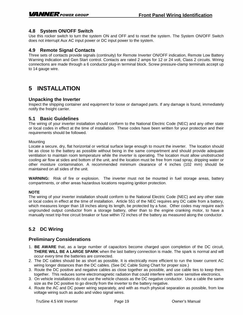
Front Panel Wiring Identification
TruSine 4.5 kW Inverter Page 18 Owners Manual
4 Front Panel Wiring Identification
PO W ER O N
C HA SSISG R O UN D
PO W ER
O F F / O NA C O U TPU T
C IR CU IT B R EAK ER
B AT T. B AT T.TEM PB AT TER Y
SEN SO R
V-N ETPO RT
SER IA LPO RT
IN V. O N
LO W BA T T.
4.5 kW Power Inverter
G E N STA RT
FO R C O N NEC T IO N T OC LA SS 2 C IR C UITS O N LY
A C IN
A C O U T
Front Panel
All field wiring enters the TruSine housing through the front panel. This is the bottom surface when the unit isoriented in the wall mounted position.
4.1 AC Input & Output WiringThe AC wiring compartment is located on the left side of the unit. The compartment contains a removableaccess cover and two cable clamps for the AC input and AC output wiring. Inside the compartment is a terminalstrip for making AC input and AC output connections.
NOTEThe AC output voltage and the required Aux AC input voltage of Model TSC24-4500 is 120 VAC, 60Hz.
The AC output voltage and the required Aux AC input voltage of Model TSC24-4500D is 120/240 VAC,60Hz, single phase, 3 wire. L1 and L2 are 180 degrees out of phase and cannot be tied together. The unitmay be damaged if the AC input power is not 180 degrees out of phase. Examples of unacceptable powerare two phases from a three phase generator or power from two separate 120 volt generators.
4.2 DC (Battery) WiringA DC wiring compartment is located behind the wiring panel on the right side of the unit. The compartmentcontains a removable access cover and two cable clamps for the battery positive and battery negative cables.The inverter’s battery cable terminal lugs can accommodate cable sizes up to 250 MCM.
4.3 System ON IndicatorThe light emitting diode (LED) indicates that the System ON/OFF Switch is ON.
4.4 Battery Temperature Sensor PortThis is an RJ-11 (4-wire) jack for optional Battery Temperature Sensor.
4.5 V-NET Port / TSR-2 Remote Control PortThis is an RJ-11 (6-Wire) jack for communications with the optional TSR-2 Remote Control / Operator InterfacePanel.
4.6 Serial Interface PortThis is an RJ-11 (6-Wire) jack for RS-232 serial communications.
4.7 Inverter Output Circuit BreakerThis 20-Amp circuit breaker provides over current protection for Inverter AC output and the Battery Charger ACinput. This breaker does not protect the Aux AC passthrough power.
Front Panel Wiring Identification
TruSine 4.5 kW Inverter Page 19 Owner’s Manual
4.8 System ON/OFF SwitchUse this rocker switch to turn the system ON and OFF and to reset the system. The System ON/OFF Switchdoes not interrupt Aux AC input power or DC input power to the system.
4.9 Remote Signal ContactsThree sets of contacts provide signals (continuity) for Remote Inverter ON/OFF indication, Remote Low BatteryWarning indication and Gen Start control. Contacts are rated 2 amps for 12 or 24 volt, Class 2 circuits. Wiringconnections are made through a 6 conductor plug-in terminal block. Screw pressure-clamp terminals accept upto 14 gauge wire.
5 INSTALLATION
Unpacking the InverterInspect the shipping container and equipment for loose or damaged parts. If any damage is found, immediatelynotify the freight carrier.
5.1 Basic GuidelinesThe wiring of your inverter installation should conform to the National Electric Code (NEC) and any other stateor local codes in effect at the time of installation. These codes have been written for your protection and theirrequirements should be followed.
MountingLocate a secure, dry, flat horizontal or vertical surface large enough to mount the inverter. The location shouldbe as close to the battery as possible without being in the same compartment and should provide adequateventilation to maintain room temperature while the inverter is operating. The location must allow unobstructedcooling air flow at sides and bottom of the unit, and the location must be free from road spray, dripping water orother moisture contamination. A recommended minimum clearance of 4 inches (102 mm) should bemaintained on all sides of the unit.
WARNING: Risk of fire or explosion. The inverter must not be mounted in fuel storage areas, batterycompartments, or other areas hazardous locations requiring ignition protection.
NOTEThe wiring of your inverter installation should conform to the National Electric Code (NEC) and any other stateor local codes in effect at the time of installation. Article 551 of the NEC requires any DC cable from a battery,which measures longer than 18 inches along its length, be protected by a fuse. Other codes may require eachungrounded output conductor from a storage battery, other than to the engine cranking motor, to have amanually reset trip-free circuit breaker or fuse within 72 inches of the battery as measured along the conductor.
5.2 DC Wiring
Preliminary Considerations
1. BE AWARE that, as a large number of capacitors become charged upon completion of the DC circuit,THERE WILL BE A LARGE SPARK when the last battery connection is made. The spark is normal and willoccur every time the batteries are connected.
2. The DC cables should be as short as possible. It is electrically more efficient to run the lower current ACwiring longer distances than the DC cables. (See DC Cable Sizing Chart for proper size.)
3. Route the DC positive and negative cables as close together as possible, and use cable ties to keep themtogether. This reduces some electromagnetic radiation that could interfere with some sensitive electronics.
3. On vehicle installations do not use the vehicle chassis as the DC negative conductor. Use a cable the samesize as the DC positive to go directly from the inverter to the battery negative.
4. Route the AC and DC power wiring separately, and with as much physical separation as possible, from lowvoltage wiring such as audio and video signal wires.

Installation
TruSine 4.5 kW Inverter Page 20 Owners Manual
5. DC power input cables which pass through steel or other ferrous metal walls need to pass through the samehole. If two holes are required, cut a slot connecting the two holes to prevent a transformer effect.
6. Do not allow wire fragments or metal shavings to fall into the DC wiring compartment or to enter the inverterin any way. Severe inverter damage will result which is not covered by the warranty.
7. Do not connect the inverter to the battery at this time. Final battery connections will be made after allinstallation issues have been inspected.
8. WARNING: A poorly made high current connection may result in risk of fire and personal injury.9. WARNING: Be sure of the polarity of the DC input wiring. Reverse polarity may severely damage your
inverter and is not covered under warranty. Risk of fire or explosion of batteries may occur due to very highcurrents.
10.A DC fuse is required to properly protect the inverter.11.The table below shows the recommended minimum cable size which should be used. Wire sizing charts
published in the NEC may allow a greater amp capacity than we recommend. We have sized the cable for amaximum voltage drop to maintain better performance of your inverter installation. The inverter’s DC cableterminal lugs can accommodate cable sizes up to 250 MCM.
TruSine 4500 DC Cable and Fuse Sizing Chart
Model Number TSC24-4500 and TSC24-4500DDistance from battery to inverter in feet(Length of cable is 2 times the distance.)
Cable Size4/0 16
250MCM 19 Fuse Bussmann ANL500 Vanner 03646 Fuse Holder Bussmann 4164 Vanner 03637
DC Wiring Installation
The DC input terminals are located in the field wiring compartment located at the front right side of the unit andaccessed from the top. The connections are compression terminals which require a stripped cable and aretightened by an Allen wrench. The positive and negative cables enter the compartment through separate strainreliefs located at the right front of the unit.
WARNINGNever make electrical connections "live". Make the connections to the inverter first and the battery last. Makecertain the ON/OFF control switch on front of inverter is in the OFF position before connecting to the battery.
NOTESevere damage to the inverter will result, which is not covered under warranty, if wire fragments or other metalparticles enter the inverter through the DC wiring compartment.ProcedureStep 1: Turn the inverter OFF and disconnect all AC and DC power to the wiring harness. Make sure power
to the inverter wiring is disconnected. Verify that the inverter is turned OFF (the Inverter ON-OFFswitch is in the OFF position).
Step 2: Select a location for the unit. An ideal installation location has the following characteristics:• Close to the battery (usually within six feet).• Protected from the weather.• Well ventilated.
Step 3: Route DC input cables. Route the negative and positive DC input cables from the inverter to thebattery. If required, protect cables where they contact hard, sharp edges.
Step 4: Install the in-line fuse. Install the in-line fuse in the red, positive DC input cable between the batteryand inverter, within 18 in. of the battery or DC wiring bus system.
Step 6: Connect the inverter to the battery.A) Remove the cover plate on the DC cable compartment exposing the positive and negative Allen head
terminal lugs.B) Remove the two Allen screws from the terminal lugs.C) Strip the positive and negative DC cable ends 3/4 in.

Installation
TruSine 4.5 kW Inverter Page 21 Owner’s Manual
D) Insert the black, negative (-) cable end through the strain relief and into the negative terminal lug. Besure that all cable strands are completely in the lug.
E) Insert the Allen screw into the negative terminal block and tighten to 275 inch-pound.F) Insert the red, positive (+) cable end through the strain relief and into the positive terminal lug. Be
sure that all cable strands are completely in the lug.G) Insert the Allen screw into the positive terminal block and tighten to 275 inch-pounds.H) Tighten the two cable clamps.I) Inspect the DC cable compartment to ensure that no foreign particles are present.J) Replace the cover plate over the DC cable compartment.K) Repeat steps E and G every 30 days.
Step 7: Verify Installation. Verify all connections are tight and bright and the cables are secure.
5.3 AC Wiring
Preliminary Considerations
1. Output and Input Voltages The AC output voltage and required Aux AC input voltage of Model TSC24-4500 is 120 VAC, 60Hz.
The AC output voltage and required Aux AC input voltage of Model TSC24-4500D is 120/240 VAC, 60Hz,single phase, 3 wire. L1 and L2 are 180 degrees out of phase and cannot be tied together. The unit maybe damaged if the AC input power is not 180 degrees out of phase. Examples of unacceptable power aretwo phases from a three phase generator or power from two separate 120 volt generators.
2. AC Wire Size To properly size the AC input and output wiring the installer must consider the inverter output capability, theinverter passthrough capability and the battery charger input requirement. The AC input/output terminalstrip is a compression lug style which will accept up to #6 AWG wire. Model TSC24-4500 – The 37.5 amp at 120 volt (4500 watt) inverter output capability requires #8 AWG wireminimum be used for the AC output. The AC transfer switch is rated 30 amps at 120 volts. Use input wire up to #6 AWG sized to suit the AC input source. The AC output wire should be the samesize as the AC input wire but not less than #8 AWG. Model TSC24-4500D – The 18.75 amp at 240 volt (4500 watt) inverter output capability requires #12 AWGwire minimum be used for the AC output. The AC transfer switch is rated 30 amps at 240 volts. Use input wire up to #10 AWG sized to suit the AC input source. The AC output wire should be the samesize as the AC input wire but not less than #12 AWG.
3. The AC Input and Output wiring compartment is accessed from the top left side of the unit. Field wires arebrought in through two cable clamps to the terminal strip identifying the “AC Input” and “AC Output”terminals. Model TSC24-4500 – The 120VAC Input and AC output terminals are labeled L1, N, and G. Model TSC24-4500D – The 240VAC input and AC output terminals are labeled L1, L2, N and G.
4. AC feedback will cause damage to the inverter! The power distribution circuits must be designed to preventAC power from an external source (shore power or a generator) from feeding back into the inverter's ACoutput.
5. The inverter AC output must be wired to a Ground Fault Circuit Interrupter (GFCI) to ensure a safeinstallation. Always maintain an isolated neutral downstream from the GFCI to prevent nuisance tripping.
6. NEC ‘Branch Circuit Rated’ circuit breakers must be installed in all installations having Aux AC input.
7. The CHASSIS BONDING LUG located on the front of the unit has been provided for safety to preventpossible shock hazards. Connect a #8 AWG minimum size wire to this terminal and then to chassis of thevehicle, the installation's grounding system, or to earth ground.Failure to connect the chassis bonding lug to the chassis of the vehicle, the installation's grounding system,or to earth ground may result in a lethal shock hazard.
AC Wiring Procedure
Step 1: Connect the AC output. Remove the cover of the AC wiring compartment to expose the AC

Installation
TruSine 4.5 kW Inverter Page 22 Owners Manual
input/output terminal strip. Identify the lower terminals labeled “AC Output”. Insert the field wiresthrough the lower strain relief into the AC wiring compartment. Tighten the strain relief. Connect thefield wires to the proper AC output terminals.
Step 2: Connect AC Input. Identify the terminal strip’s upper terminals labeled “AC Input”. Insert the fieldwires through the upper strain relief into the AC wiring compartment. Tighten the strain relief.Connect the field wires to the proper AC input terminals. Replace the AC wiring compartment cover.
Step 3: Connect Bonding Lug. Use a #8 AWG or larger copper conductor to connect the chassis bonding lugto the chassis of the vehicle, the installation’s grounding system, or to earth ground.
Step 4: Verify Installation. Verify all connections are tight and secure for maximum performance.
5.4 TSR-2 TruSine Remote Control Panel Installation
Unpacking the Optional TSR-2 TruSine Remote Control Panel
Inspect the shipping container and equipment for loose, damaged, or missing parts. If any damage is found,immediately notify the freight carrier.
Installing the TSR-2 TruSine Remote Control Panel
The TSR-2 TruSine Remote Control Panel may be located near the inverter or at a convenient remote location. The unit is supplied with a 25’ long twisted data cable with a 6-pin RJ-11 connector at each end.
Step 1: Locate a suitable clean dry location for installation. The TSR-2 front panel is 6½ wide x 5¼ high. Theback housing is 5¾ wide x 4½ high x 1¾” deep with cable entry on the right side.
Step 2: Route the data cable from the remote panel mounting area to the inverter.
Step 3: Plug the data cable into the RJ-11 modular jack labeled “V-NET” on the front of the inverter.
Step 4: Plug the data cable into the RJ-11 modular jack on right side of the TSR-2.
Step 5: Mount the TSR-2 Remote Panel using four #8 screws (not included).
5.5 System Start-up and Testing
Step 1: Completely install the TruSine 4500 Inverter/Charger following the system design considerations andinstructions provided previously in this manual.
Step 2: Place the System On/Off switch located on the front of the inverter in the OFF position.
Step 3: Verify that the external GFCI breaker is reset and connect an AC load, such as a 100-Wattlight.
Step 4: Turn ON the battery DC power to the inverter.
Step 5: Turn ON the AC shore power (or generator) to supply the AC input power to the system.
Step 6: Place the System On/Off switch located on the front of the inverter to the ON position.
Step 7: The green Power On LED on the front of the inverter should come ON.
Step 8: The TSR-2 TruSine Remote Control Panel (optional), if used, should display the main menu.
Step 9: The AC output test light should be ON, indicating the presence of shore power and correct operationof the AC transfer switch.
Step 10: Disconnect the AC shore power input. The AC output test light should immediately quickly blink once,indicating the transfer switch transferred the test light from shore power to inverter power.
Step 11: At this point, apply AC loads up to 4,500 watts to verify full-power operation.
Step 12: Apply shore power. After a delay the AC output test light should blink indicating the transfer of theload from inverter power to shore power.
Step 13: Test the battery charger operation:

Installation
TruSine 4.5 kW Inverter Page 23 Owner’s Manual
A) Discharge the battery by placing the AC load on the system and operating the inverter, (remove shorepower input).
B) When the battery charge level is low, the inverter will turn off.
C) Apply shore power and observe the battery charger operation. Connect an ammeter to the DC cablesbetween the inverter and the battery to monitor the current (DC amps), and a volt meter to the battery tomonitor the battery voltage. The battery charger will step through its sequence and stop in the floatmode.
Step 14: The system is now ready for operation.
6 GENERAL INFORMATION SECTION
6.1 Generic Inverter Description
In general, an inverter converts DC electrical power into AC power. This power can be used to operate variousAC-driven appliances. Typical DC power sources include batteries that store electrical energy, powergenerated from a vehicle alternator or renewable energy sources such as photovoltaic (solar) panels.
The most common battery systems are 12 or 24 volt. Some systems, however, operate on higher voltagessuch as 32, 36, 48, or 120 volts. The most common inverter AC output power is 120 volts at a frequency of 60Hz. Some inverters, however, are designed to produce 240 volts, or both 120 and 240 volts at 60 Hz. Becausesome countries use power of different voltage and frequency (e.g., 230 volts at 50 Hz), inverters are availableto conform to these requirements.
The three available inverter types are distinguished by the type of AC output wave form they produce. Thiswave form affects the AC loads they operate. This section provides an overview of these inverter types,including the advantages and disadvantages associated with using each type.
Sine Wave InverterSine wave inverters produce an AC output wave form like power produced by the electric utility companies androtating generators. The sine wave inverter’s wave form is characterized by the highest peak voltage andsmooth voltage transitions (no square wave components). Such inverters are the most costly of the threeinverter types because they contain additional electronics to produce the required wave form. A measure of thesine wave quality is Total Harmonic Distortion (THD), and is expressed in a percentage. The lower the THDthe higher the quality of the sine wave power.
Modified Sine Wave InverterModified sine wave inverters are sometimes called “quasi sine wave inverters” or “modified square waveinverters.” Modified sine wave inverters generally cost more than square wave inverters because they containadditional electronic circuitry to produce true RMS regulated AC output. Modified sine wave inverters havehigher AC peak voltages than square wave inverters, and automatically control the width of the AC output waveform to regulate the output voltage (pulse-width modulation). The shape of the modified sine wave inverter’swave form includes a square wave component. It is stepped in such a way, however, to closely approximatethe true sine wave produced by the electric utility companies. Although this wave form has a higher peakvoltage than do square wave inverters, its peak voltage is not as high as a pure sine wave. Therefore, ACloads containing power supplies might not always operate properly on the modified sine wave inverter.
Square Wave InverterThe square wave inverter is a low cost device that produces a pure square wave AC power output. This ACpower can be an accurate 60 Hz frequency if it is crystal controlled. It does not have the necessary peakvoltage to properly operate many AC appliances that contain electronic power supplies (e.g., computers, TVs,and VCRs). The square wave is appropriate when operating AC loads such as resistive heating devices.
6.2 Inverter Sizing
Output Power Rating - Power output is an important consideration when purchasing an inverter. Power isdefined as the rate that a device produces (or uses) electrical energy. This rate is measured in watts orkilowatts (one kilowatt equals 1,000 watts), or sometimes in voltamps. Voltamps are roughly equal to watts and

General Information
TruSine 4.5 kW Inverter Page 24 Owners Manual
are obtained by multiplying volts times amps produced or used by a device
To properly determine an inverter size (in watts) for your application decide which AC loads you plan to operate. Inverter size is the sum of the wattages of the AC loads that you wish to run at the same time, plus a safetyfactor, say 10 to 20 percent.
Continuous Output Power - Continuous power is defined as the AC power in watts (or voltamps) an inverter canproduce on a continuous basis. The ambient temperature can affect the continuous rating of the inverter, and isnormally specified, e.g., 25° C. or 40°C.
Surge Output Power - Inverter power can also be rated in terms of surge power. Surge power is the short termduration of AC power that the inverter can produce. It is often specified as the watts (or voltamps) that canoperate a resistive load for two or three seconds. Sometimes this is specified in AC amps because the invertermay allow output voltage to drop (which would reduce is wattage). Like continuous power, the surge rating isaffected by ambient temperature.
Note - Regardless of an inverter’s power ratings, an inverter’s AC output capability is only as strong as the DCsource. To achieve optimum performance an inverter must be installed with properly sized cable and have anample DC supply. Recommended cable sizes are listed in the DC Cable and Fuse Chart. The followingsections in this manual will cover the basic information required to properly size the inverter battery and thevehicle alternator. Keep in mind that if information in this manual directly conflicts with instructions from aspecific battery or other equipment manufacturer, Vanner recommends that those manufacturer'srecommendations be followed.
6.3 DC Power Consumption
An inverter takes in DC power, and produces AC power to operate AC loads. In general, we can see a directrelationship between DC input power and AC output power. This allows us to establish the following rule ofthumb:
For 12 volt DC inverters: Output Watts ÷ 10 = DC Input Amps.
For 24 volt DC inverters: Output Watts ÷ 20 = DC Input Amps.
This rule of thumb can be used to estimate the minimum alternator size required for your application. It mayalso be used in calculating the minimum size battery required when operating from an alternator and batterycombination; a photovoltaic panel and battery combination; or when operating from battery alone. The followingexamples should help to clarify the use of this rule of thumb.
Example AWhat is the DC current draw of a 12 volt DC input inverter when it is operating a vacuum cleaner with aname plate rating of 6 amps at 120 volts AC?
The appliance rating is given in amperes, so we must first calculate the power it consumes. Then therule of thumb can be used to find the DC input current of the inverter.
Output power = 120 volts x 6 amps = 720 watts, andDC input current = 720 ÷ 10 = 72 amps DC.
Example BWhat is the DC current draw of a 24 volt DC input inverter when it is operating a toaster with a nameplate rating of 1050 watts at 120 volts AC?
Since the appliance is rated in watts, the rule of thumb can be applied directly:
DC input current = 1050 ÷ 20 = 52.5 amps DC.
This information on estimating the DC input current requirement for an inverter will allow you to size analternator or charging system to supply an inverter for continuous operation. This rule of thumb will be usedlater in the discussions on battery sizing.

General Information
TruSine 4.5 kW Inverter Page 25 Owner’s Manual
6.4 Battery Terminology and Ratings
Batteries used for automotive applications generally are lead-acid storage batteries. They can be separatedinto two categories according to their use: engine cranking batteries and deep cycle batteries. The enginecranking battery is specifically designed to supply hundreds of amps for a short period of time to start anengine. Cranking an engine usually uses a small portion of the battery's total capacity and once the engine isrunning, the battery is quickly recharged by the engine's alternator. The deep cycle battery is specificallydesigned to deliver current for extended periods of time and can be almost totally discharged beforerecharging.
The "deep cycle" lead-acid battery is designed to withstand the deep discharge/recharge cycling that is typicalof most inverter installations. These batteries are available in the "maintenance free" style where the electrolytedoes not need to be checked or replenished and they also are available in the gelled electrolyte style or "GelCells". Deep cycle batteries are generally advertised for use in recreational vehicles or boats and aresometimes referred to as RV or marine batteries.
Battery Council International (BCI) is a voluntary industry organization which has helped to standardize batteryratings. Ratings in use at this date are:
CCA (Cold Cranking Amperes): Rating in amps a battery cold soaked at 0°F or –20°F will carry for 30seconds and maintain a minimum terminal voltage of 7.2.
MCA (Marine Cranking Amperes): Rating in amps a battery cold soaked at 30°F will carry for 30 secondsand maintain a minimum terminal voltage of 7.2.
RC (Reserve Capacity): Rating in minutes a battery will carry a 25 amp load at 80°F and maintain aminimum terminal voltage of 10.5.
AH (Amp Hour): At the “20 Hour Rate”, also called the C Rate, a battery having a 100 AH rating mustcarry a 5 amp load for 20 hours (100AH ÷ 20 hours = 5 amps) and maintain a terminal voltage of10.5 at 80°F. (Two 100AH 12volt batteries connected in series provides 100AH at 24 volts. Two 100AH 12volt batteries connected in parallel provides 200 AH at 12 volts.).
CCA and MCA are used for sizing an engine cranking battery and have no bearing on a battery's cycling ability.RC is a rating given to cranking batteries to provide an idea of how long a vehicle could be driven if the vehiclecharging system were to fail.
The most important and probably least understood battery capacity rating is the ampere-hour. One simplereason the AH rating is misunderstood is that a battery rated at 100 AH cannot always deliver 100 AH. Theunderlying reason is the efficiency with which the battery converts its chemical energy into electric energy. TheAH capacity of a battery is affected in the following ways:
Discharge rate: A battery becomes less efficient as the discharge current increases. For example, a typical100 AH battery is specified to be able to deliver 5 amps for a period of 20 hours. If the discharge current wereincreased to 25 amps, the capacity will be reduced to approximately 75 AH (25 amps x 3 hours = 75 AH).
Operating temperature: A battery becomes less efficient at lower temperatures. Most battery manufacturersspecify the battery AH capacity at 80° F. At a temperature of 32° F, the same battery will have only about 65%of its rated capacity even though it may be fully charged. At a temperature of 0° F, a battery's capacity will bereduced to about 40% of its rated capacity.
Battery age: As a battery is used, the active material on the battery plates will gradually deteriorate and becomeuseless. As the battery gets older, there will be less and less useful material left on the plates and theoperating time will become noticeably shorter. A battery will age faster (loose active material from its platesfaster) if it is deeply discharged regularly, if it is left in a discharged state for extended periods of time, or if it isrepeatedly overcharged.
Series and/or Parallel Connected Batteries: Up to this point we have spoken of the battery as if it were a singlebattery. In some cases this may be true, but in general, the battery may be made up of several individualbatteries electrically connected together to form a "Bank" of batteries. Batteries can be connected in series,parallel, or a combination of series and parallel as long as all of the batteries in the bank are of equal ratings,are from the same manufacturer, and are the same age. Old and new batteries should never be mixed in thesame battery bank. Mixed batteries will result in accelerated battery failure due to the unequal discharge andrecharge rates.
A series connection is where two or more batteries are connected positive (+) to negative (-). The total voltage

General Information
TruSine 4.5 kW Inverter Page 26 Owners Manual
of the battery bank is the sum of the voltage of each battery in the bank. For example, most large customcoaches require a 24 volt battery to crank the large diesel engine. The 24 volts is usually provided byconnecting two 12 volt batteries in series, and sometimes by connecting four 6 volt batteries in series. Theratings of the series connected battery bank remain the same as the individual battery's rating. If the batterybank is made up of two 8D size batteries in series, each with a CCA of 1050 amps, 425 minutes RC, and amp-hour capacity of 200 AH, then these individual battery ratings are also the ratings of the entire 24 volt batterybank.
Parallel connected batteries are batteries which are connected positive to positive and negative to negative.They form a battery bank that has the same voltage as each individual battery. The ratings of a parallelconnected battery bank, in general, are the sum of the individual batteries. For instance, if two 8D batteries areconnected in parallel, and each battery has the ratings given in the paragraph above, then the ratings for thebattery bank become 2100 CCA, 900 minutes RC, and approximately 400 amp-hours. Parallel connectedbatteries should be of the same voltage and rating to achieve optimum battery life and performance.
6.5 Sizing the Inverter Battery
Sizing a battery system for an inverter application can be a very tedious task if all the different variables, suchas discharge rate, depth of discharge, and operating life time are included in the calculations. To simplify thesecalculations and get a reasonably correct battery size, we will assume: 1) A 50% depth of discharge for thepurpose of obtaining a reasonable life time for a reasonable battery system cost, 2) there is no charge currentinto the battery system, 3) the batteries are in a fully charged state at the beginning of the discharge cycle, and4) the DC current draw from the battery does not exceed 1/3 the C rate for any length of time.
Follow the steps listed below to find the AH capacity required for your application.
Step 1: Make a list of each appliance, its power requirement in watts, and the amount of time in hours it willbe operating between charging cycles. Note: If the appliance is rated in amperes (amps) instead ofwatts, multiply the amps by the voltage (120 or 240) to get watts.
Step 2: Calculate the watt-hours required for each appliance by multiplying the power requirement by theoperating time of that appliance.
Step 3: Calculate the total watt-hours needed by adding together the watt-hours of each appliance.
Step 4: Find the amp-hours consumed by dividing the total watt-hours found in step 3 by 10 for 12 volt DCsystems or by 20 for 24 volt DC systems.
Step 5: Multiply the amp-hours consumed by 2 (for 50% depth of discharge) to get the battery amp-hourcapacity desired.
Example 1: Follow Steps 1 through 3 (above)Appliance Power Rating Operating Time Watt-Hours Consumed
TV, VCR, Stereo 225 watts 2.5 hours 563 watt-hoursSmall Refrigerator 300 3.8 1,140Microwave 800 0.3 240
TOTALS 1,943 watt-hours
Step 4: Amp-hours consumed = 1943 watt-hours ÷ 20 = 97.15 amp-hours for 24 a volt system.
Step 5: The minimum battery size for this application is 2 x 97.15 = 194.3 amp-hours.
6.6 Battery and Charging System Considerations
The Battery and DC Charging System is a very important part of your inverter installation responsible to supplyall of the DC power required by the inverter. The system normally consists of the primary charger (enginealternator or photovoltaic array), a secondary charger, if used, the battery, and other equipment which may beused such as battery isolator diodes. The complexity of the system depends on the way the inverter is used. In some cases, such as utility or service vehicles, the system may be as simple as the engine alternator andthe cranking battery which also powers the inverter. In most cases, additional equipment is needed to provideadditional DC power and/or protection. These systems can be grouped into two categories, the single battery

General Information
TruSine 4.5 kW Inverter Page 27 Owner’s Manual
and the dual battery systems.
In the single battery system, there is one battery which is shared for starting the engine and operating theinverter. This is a common practice in a service vehicle where the engine runs all the time and allows thealternator to provide continuous charging for the battery. In this case, the inverter can be connected directly tothe engine cranking battery. The most important detail of this system is the alternator output rating. Thecontinuous output of the alternator needs to be at least as much as the total DC current draw on the system.The total DC current draw must include the inverter, warning lights, radios, engine controls, and any otherdevice connected to the DC system. Care should be used when operating this type of system while the engineis shut off. The inverter will shut itself OFF for low battery but most other DC loads will not. The vehicle batterymay be drained too low to restart the engine.
The dual battery system uses two separate batteries, one for starting the engine and operating the vehicle'ssystems, and one for operating the inverter. The two batteries are usually referred to as the "cranking battery"and the "house or auxiliary battery" respectively. The two separate batteries are usually charged from thesame source, the engine alternator, but are separated by a device called a battery isolator. The battery isolatorallows DC current to flow from the alternator into each battery, but blocks current from flowing from one batteryto the other. This is a must to protect the cranking battery in recreation vehicles, boats and other vehicleswhere the inverter needs to be operated when the engine (therefore the alternator) is not running.
6.7 Battery Charging Guidelines
CAUTIONThe following information on battery charger setup adjustments should be used as guidelines only. Vannerstrongly recommends that you contact the manufacturer of your batteries to obtain the specific chargingsetup values for the type and model of battery you are using. This is due to the fact that battery chargingparameters such as bulk, absorption, float and equalize voltages vary from one manufacturer to another,and that gel cell batteries have different parameters than wet lead acid batteries. An improperly adjustedbattery charger may cause damage to your batteries!
The maximum charging current for a battery is usually equal to 20% of the battery's Amp hour capacity (“C”) forlead acid batteries, and 50% of the battery's C for gel cell batteries. The C rate is numerically equal to theamp-hour capacity for the battery. For example, a 280 amp-hour battery has a C rate of 280 amps, and themaximum charge rate would be 56 amps DC. (Note that this is not the same as the battery's Cold CrankingAmp rating.) You should also take into consideration that if two batteries are connected in parallel their amp-hours add but if batteries are connected in series their amp-hours remain the same.
7 MAINTENANCE & TROUBLESHOOTING
7.1 Preventative Maintenance
There are no user serviceable components inside the TruSine Inverter/charger. For service refer to VannerPower Group or other qualified service personnel.
Maintenance Items:
For continued reliability and safety, a monthly maintenance program should be implemented to include thefollowing:
1. Check to insure that all AC and DC wiring is secure and connections are tight and corrosion free.
2. Check air ventilation openings for dust and other obstructions.
3. Examine receptacle, indicators and switches for cracks and breaks.
Trouble Shooting
Problem: The TSR-2 Remote Control Panel does not respond.
Check: Suspect Step 92 Inverter Address has been changed from 1. Change back to 1 using Demo

General Information
TruSine 4.5 kW Inverter Page 28 Owners Manual
Mode. See TSR-2 Remote Control Panel operation.
Warranty
TruSine 4.5 kW Inverter Page 29 Owner’s Manual
8 Warranty
NORTH AMERICAN LIMITED WARRANTY
Vanner Inc., doing business as The Vanner Power Group, referred to herein as Vanner, warrants that thisproduct is free from defects in materials and workmanship for a period of two (2) years from date of installationor two and one half (2 1/2) years from date of manufacture, whichever is less if and only if the followingrequirements are complied with:
1. The product is installed and checked out properly according to all guidelines, instructions, andcheckout procedures set forth in the product Installation and Operating Manual.
2. The installer records all checkout data required and completes, signs, and returns the warrantyregistration card to Vanner within ten (10) days after installation.
3. The product was purchased after January 1, 2000.
Vanner does not warrant its products against any and all defects when: defect is a result of material orworkmanship not provided by Vanner; normal wear and tear, or defects caused by misuse or use in contrary toinstructions supplied, neglect, accident, reversed polarity, unauthorized repairs and/or replacements.
All warranties of merchantability and fitness for a particular purpose: written or oral, expressed or implied, shallextend only for a period of two (2) years from date of installation or two and one half (2 1/2) years from date ofmanufacture, whichever is first. There are no other warranties that extend beyond those described on the faceof this warranty. Some states do not allow limitation on how long an implied warranty lasts, so the abovelimitations may not apply to you.
Vanner does not undertake responsibility to any purchaser of its product for any undertaking, representation, orwarranty made by any dealers or distributors selling its products beyond those herein expressed unlessexpressed in writing by an officer of Vanner.
Vanner does not assume responsibility for incidental or consequential damages, including, but not limited to,responsibility for loss of use of this product, removal or replacement labor, loss of time, inconvenience,expense for telephone calls, shipping expense, loss or damage to property, or loss of revenue. Some states donot allow the exclusion or limitation of incidental or consequential damages, so these limitations may not applyto you.
Vanner reserves the right to repair, replace, or allow credit for any material returned under this warranty. Anydamage caused by the customer will be charged or deducted from the allowance.
All warranty work will be performed at Vanner’s factory, or authorized repair facility utilizing a valid WarrantyAuthorization Number (WAN) prior to repair. Products shall be delivered to Vanner’s facility, freight prepaid andfully insured. Products repaired under warranty, or replacement parts or products will be returned to NorthAmerican location prepaid via same transportation means and level of service as received, unless directedotherwise. Prepaid freight policy does not apply to locations outside North America.

TruSine 4.5 kW Inverter/Charger System
TruSine 4.5 kW Inverter Page 30 Owners Manual
Vanner Power Group4282 Reynolds DriveHilliard, Ohio 43026
1-800-AC POWER(1-800-227-6937)Tel: 614-771-2718Fax: 614-771-4904
www.vanner.come-mail: [email protected]
Manual Number D98771 Rev BMarch 1, 2000 Printed in USA