trueDGS Angle Beam Probes
4
trueDGS ® Angle Beam Probes Ultrasonic Probes A New Level of DGS Accuracy and Reliability for Single Element Angle Beam Probes and Ultrasonic Phased arrays GE Measurement & Control Solutions GE imagination at work
Transcript of trueDGS Angle Beam Probes

trueDGS® Angle Beam Probes
Ultrasonic Probes
A New Level of DGS Accuracy and Reliability for Single Element Angle
Beam Probes and Ultrasonic Phased arrays
GE
Measurement & Control Solutions
GE imagination at work

New, patent-pending trueDGS technology from the
Inspection Technologies business of GE Measurement &
Control Solutions has allowed the company to develop
and introduce a range of ultrasonic trueDGS angle beam
probes which:
DGS method.
Provide the same accuracy as circular straight beam
probes.
Are available as single elements and phased array
transducers.
Ensure accurate, compliant ultrasonic inspection in
a wide range of applications.
Are accompanied by the associated software.
The DGS method was originally developed for straight
Today’s single element angle beam probes and ultrasonic
Accuracy Using the DGS Technique
to straight beam compression probes because of the
refraction at the material interface. This means that there
can be deviations in DGS evaluations. This often results
workpiece scrap or reworking.
trueDGS and
true
true
10
10
1
10
40
30
20
10
0
1
ƒ->
3m
m
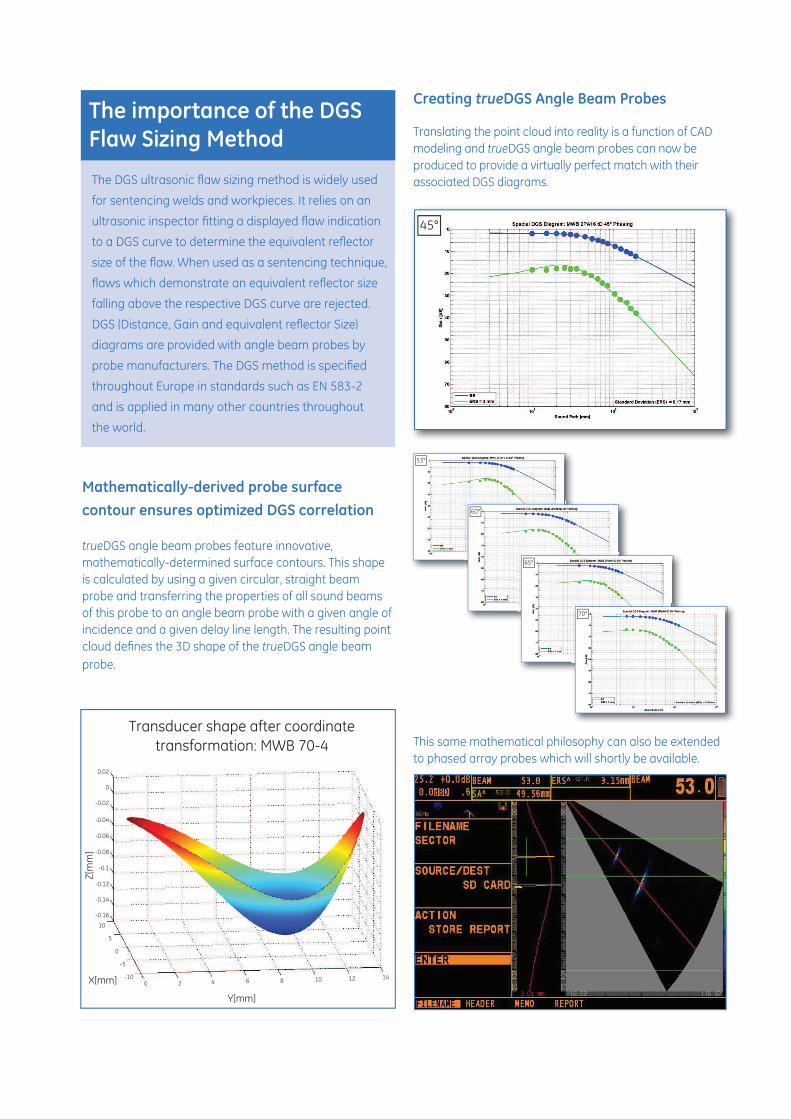
trueDGS angle beam probes feature innovative,
mathematically-determined surface contours. This shape
is calculated by using a given circular, straight beam
probe and transferring the properties of all sound beams
of this probe to an angle beam probe with a given angle of
incidence and a given delay line length. The resulting point
trueDGS angle beam
probe.
true
Translating the point cloud into reality is a function of CAD
modeling and trueDGS angle beam probes can now be
produced to provide a virtually perfect match with their
associated DGS diagrams.
This same mathematical philosophy can also be extended
to phased array probes which will shortly be available.
45°
60°
65°
70°
Transducer shape after coordinate
transformation: MWB 70-4
0.02
0
-0.02
-0.04
-0.06
-0.08
-0.1
-0.12
-0.14
-0.16
10
-100 2 4 6 8 10 12 14
5
-5
0
for sentencing welds and workpieces. It relies on an
falling above the respective DGS curve are rejected.
diagrams are provided with angle beam probes by
and is applied in many other countries throughout
the world.

www.ge-mcs.com
β
MWB 45-2tD 500678 2 45 18 Type 1
MWB 60-2tD 500679 2 60 16 Type 1
MWB 70-2tD 500680 2 70 18 Type 2
MWB 45-4tD 500681 4 45 44 Type 1
MWB 60-4tD 500682 4 60 Type 1
MWB 70-4tD 4 70 Type 2
pitch mm
MWB 2PA16tD 500684 2 16 0.89 45°-70° Type 2
MWB 4PA16tD 500685 4 16 0.98 45°-70° 60 Type 2
A mm B mm C mm
Type 1 20 26
Type 2
trueDGS® Probes
Regional Contact Information
50 Industrial Park RoadLewistown, PA 17044USA Germany
China
AB
C