troximity System - Metrix-Vibration System Opera• ntl 100576 B ... ntly Neva 3300 or 3300 XL 5 mm...
42
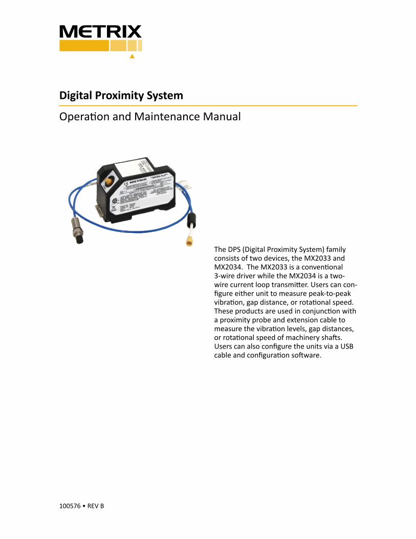
Digital Proximity System Operaon and Maintenance Manual 100576 • REV B The DPS (Digital Proximity System) family consists of two devices, the MX2033 and MX2034. The MX2033 is a convenonal 3-wire driver while the MX2034 is a two- wire current loop transmier. Users can con- figure either unit to measure peak-to-peak vibraon, gap distance, or rotaonal speed. These products are used in conjuncon with a proximity probe and extension cable to measure the vibraon levels, gap distances, or rotaonal speed of machinery shas. Users can also configure the units via a USB cable and configuraon soware.
-
Upload
truongkhue -
Category
Documents
-
view
222 -
download
0
Transcript of troximity System - Metrix-Vibration System Opera• ntl 100576 B ... ntly Neva 3300 or 3300 XL 5 mm...
Digital Proximity System
Opera� on and Maintenance Manual
100576 • REV B
The DPS (Digital Proximity System) family
consists of two devices, the MX2033 and
MX2034. The MX2033 is a conven� onal
3-wire driver while the MX2034 is a two-
wire current loop transmi! er. Users can con-
fi gure either unit to measure peak-to-peak
vibra� on, gap distance, or rota� onal speed.
These products are used in conjunc� on with
a proximity probe and extension cable to
measure the vibra� on levels, gap distances,
or rota� onal speed of machinery sha# s.
Users can also confi gure the units via a USB
cable and confi gura� on so# ware.
Doc# 100576 • REV B (April 2015) Page 2 of 42
TABLE OF CONTENTS
1. General Informa� on . . . . . . . . . . . . . . . . . . . . . . . . . . . . . . . . . . . . . . . . . . . . . . . . . . . . . . . .3
1.1 Safety Terms and Symbols . . . . . . . . . . . . . . . . . . . . . . . . . . . . . . . . . . . . . . . . . . . . . . . . . .3
1.2 General Safety Summary. . . . . . . . . . . . . . . . . . . . . . . . . . . . . . . . . . . . . . . . . . . . . . . . . . . .3
2. Overview . . . . . . . . . . . . . . . . . . . . . . . . . . . . . . . . . . . . . . . . . . . . . . . . . . . . . . . . . . . . . . . . . . . . . . . . . 4
2.1 MX2033 Three-Wire Proximity Driver . . . . . . . . . . . . . . . . . . . . . . . . . . . . . . . . . . . . . . . . . . . . . . 5
2.2 MX2034 Two-Wire Transmi! er . . . . . . . . . . . . . . . . . . . . . . . . . . . . . . . . . . . . . . . . . . . . . . . . . . . . 5
2.3 For more informa" on. . . . . . . . . . . . . . . . . . . . . . . . . . . . . . . . . . . . . . . . . . . . . . . . . . . . . . . . . . . . . 5
3. Confi guring a DPS . . . . . . . . . . . . . . . . . . . . . . . . . . . . . . . . . . . . . . . . . . . . . . . . . . . . . . . . . . . . . . . . . 6
3.1 Equipment Required . . . . . . . . . . . . . . . . . . . . . . . . . . . . . . . . . . . . . . . . . . . . . . . . . . . . . . .6
3.2 So$ ware Installa" on . . . . . . . . . . . . . . . . . . . . . . . . . . . . . . . . . . . . . . . . . . . . . . . . . . . . . . .7
3.3 Connec" ng the DPS to a Computer . . . . . . . . . . . . . . . . . . . . . . . . . . . . . . . . . . . . . . . . . .11
3.3.1 Remove the Base . . . . . . . . . . . . . . . . . . . . . . . . . . . . . . . . . . . . . . . . . . . . . . . . . . . . . . .11
3.3.2 Apply Power . . . . . . . . . . . . . . . . . . . . . . . . . . . . . . . . . . . . . . . . . . . . . . . . . . . . . . . . . . .12
3.4 Launching the DPS Confi gura" on So$ ware . . . . . . . . . . . . . . . . . . . . . . . . . . . . . . . . . . . .12
3.5 Main Screen . . . . . . . . . . . . . . . . . . . . . . . . . . . . . . . . . . . . . . . . . . . . . . . . . . . . . . . . . . . . .13
3.5.1 Command Line Op" ons . . . . . . . . . . . . . . . . . . . . . . . . . . . . . . . . . . . . . . . . . . . . . . . . . .13
3.5.2 Device Informa" on . . . . . . . . . . . . . . . . . . . . . . . . . . . . . . . . . . . . . . . . . . . . . . . . . . . . . .13
3.5.3 Device Communica" on Status . . . . . . . . . . . . . . . . . . . . . . . . . . . . . . . . . . . . . . . . . . . . .14
3.5.4 Confi gurable Device Se& ngs . . . . . . . . . . . . . . . . . . . . . . . . . . . . . . . . . . . . . . . . . . . . . .14
3.5.5 Confi rming the Confi gura" on . . . . . . . . . . . . . . . . . . . . . . . . . . . . . . . . . . . . . . . . . . . . .16
3.5.6 Prin" ng a Label . . . . . . . . . . . . . . . . . . . . . . . . . . . . . . . . . . . . . . . . . . . . . . . . . . . . . . . . .16
3.5.7 Installing the Label . . . . . . . . . . . . . . . . . . . . . . . . . . . . . . . . . . . . . . . . . . . . . . . . . . . . . .18
3.6 Using the MX2034 Buff ered Output . . . . . . . . . . . . . . . . . . . . . . . . . . . . . . . . . . . . . . . . .18
4. Verifi ca� on and Calibra� on . . . . . . . . . . . . . . . . . . . . . . . . . . . . . . . . . . . . . . . . . . . . . . . . .19
4.1 Scale Factor Verifi ca" on . . . . . . . . . . . . . . . . . . . . . . . . . . . . . . . . . . . . . . . . . . . . . . . . . . .20
4.2 Scale Factor Custom Calibra" on . . . . . . . . . . . . . . . . . . . . . . . . . . . . . . . . . . . . . . . . . . . . .24
4.2.1 Current Loop Verifi ca" on (MX2034 only) . . . . . . . . . . . . . . . . . . . . . . . . . . . . . . . . . . . .26
5. Troubleshoo� ng . . . . . . . . . . . . . . . . . . . . . . . . . . . . . . . . . . . . . . . . . . . . . . . . . . . . . . . . . .29
5.1 MX2033 and MX2034 . . . . . . . . . . . . . . . . . . . . . . . . . . . . . . . . . . . . . . . . . . . . . . . . . . . . .29
5.2 MX2034 Only . . . . . . . . . . . . . . . . . . . . . . . . . . . . . . . . . . . . . . . . . . . . . . . . . . . . . . . . . . . .30
6. Performance Graphs . . . . . . . . . . . . . . . . . . . . . . . . . . . . . . . . . . . . . . . . . . . . . . . . . . . . . . .31
6.1 Driver/Transmi! er Temperature Response . . . . . . . . . . . . . . . . . . . . . . . . . . . . . . . . . . . .31
6.1.1 MX2030/BN 3300 5 Meter System . . . . . . . . . . . . . . . . . . . . . . . . . . . . . . . . . . . . . . . . .31
6.1.2 MX2030/BN 3300 9 Meter System . . . . . . . . . . . . . . . . . . . . . . . . . . . . . . . . . . . . . . . . .34
6.1.3 Metrix/BN 7200 5 Meter System . . . . . . . . . . . . . . . . . . . . . . . . . . . . . . . . . . . . . . . . . .36
6.1.4 Metrix/BN 7200 9 Meter System . . . . . . . . . . . . . . . . . . . . . . . . . . . . . . . . . . . . . . . . . .39
6.2 Phase Delay . . . . . . . . . . . . . . . . . . . . . . . . . . . . . . . . . . . . . . . . . . . . . . . . . . . . . . . . . . . . .42
7. Trademarks and Copyrights . . . . . . . . . . . . . . . . . . . . . . . . . . . . . . . . . . . . . . . . . . . . . . . . .43
Doc# 100576 • REV B (April 2015) Page 3 of 42
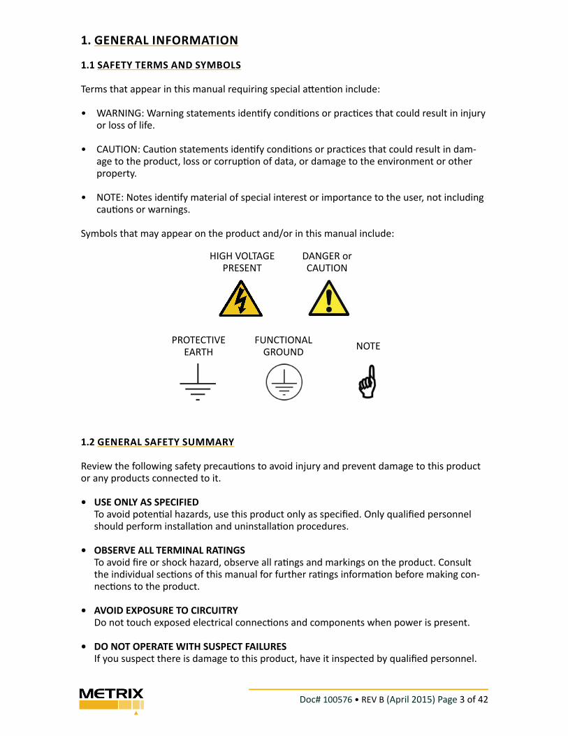
HIGH VOLTAGE PRESENT
PROTECTIVE EARTH
NOTE
DANGER or CAUTION
FUNCTIONAL GROUND
1. GENERAL INFORMATION
1.1 SAFETY TERMS AND SYMBOLS
Terms that appear in this manual requiring special a! en" on include:
• WARNING: Warning statements iden" fy condi" ons or prac" ces that could result in injury or loss of life.
• CAUTION: Cau" on statements iden" fy condi" ons or prac" ces that could result in dam-age to the product, loss or corrup" on of data, or damage to the environment or other property.
• NOTE: Notes iden" fy material of special interest or importance to the user, not including cau" ons or warnings.
Symbols that may appear on the product and/or in this manual include:
1.2 GENERAL SAFETY SUMMARY
Review the following safety precau" ons to avoid injury and prevent damage to this product or any products connected to it.
• USE ONLY AS SPECIFIEDTo avoid poten" al hazards, use this product only as specifi ed. Only qualifi ed personnel should perform installa" on and uninstalla" on procedures.
• OBSERVE ALL TERMINAL RATINGSTo avoid fi re or shock hazard, observe all ra" ngs and markings on the product. Consult the individual sec" ons of this manual for further ra" ngs informa" on before making con-nec" ons to the product.
• AVOID EXPOSURE TO CIRCUITRYDo not touch exposed electrical connec" ons and components when power is present.
• DO NOT OPERATE WITH SUSPECT FAILURESIf you suspect there is damage to this product, have it inspected by qualifi ed personnel.
Doc# 100576 • REV B (April 2015) Page 4 of 42
1.3 RECEIVING, INSPECTING AND HANDLING THE SYSTEM
Metrix ships the probe, extension cable, and driver as separate units that the user intercon-nects at the installa! on site. Carefully remove all equipment from the shipping containers and inspect it for shipping damage. If you see shipping damage, fi le a claim with the carrier
and submit a copy to Metrix Instrument Co. Include part numbers and serial numbers on all
correspondence. If no damage is apparent and the equipment is not going to be used imme-
diately, return the equipment to the shipping containers and reseal un! l ready for use. Store the equipment in an environment that is free from poten! ally damaging condi! ons such as extreme temperature, excessive humidity, or a corrosive atmosphere.
2. OVERVIEW
The Metrix Digital Proximity System module comes in two versions:
• MX2033 – 3-wire proximity driver
• MX2034 – 2-wire, loop powered proximity transmi$ er
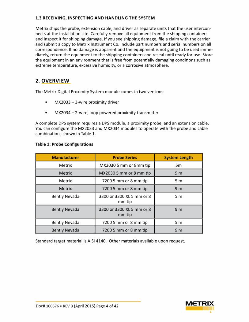
A complete DPS system requires a DPS module, a proximity probe, and an extension cable.
You can confi gure the MX2033 and MX2034 modules to operate with the probe and cable
combina! ons shown in Table 1.
Table 1: Probe Confi gura" ons
Manufacturer Probe Series System Length
Metrix MX2030 5 mm or 8mm ! p 5m
Metrix MX2030 5 mm or 8 mm ! p 9 m
Metrix 7200 5 mm or 8 mm ! p 5 m
Metrix 7200 5 mm or 8 mm ! p 9 m
Bently Nevada 3300 or 3300 XL 5 mm or 8 mm ! p
5 m
Bently Nevada 3300 or 3300 XL 5 mm or 8 mm ! p
9 m
Bently Nevada 7200 5 mm or 8 mm ! p 5 m
Bently Nevada 7200 5 mm or 8 mm ! p 9 m
Standard target material is AISI 4140. Other materials available upon request.
Doc# 100576 • REV B (April 2015) Page 5 of 42
The sec! ons below provide more module informa! on.
2.1 MX2033 THREE�WIRE PROXIMITY DRIVER
The MX2033 signal output is propor! onal to the distance between the probe ! p and the
target material. The signal output follows API Standard 670 and is compa! ble with most
con! nuous vibra! on monitoring systems. The MX2033 uses -24Vdc excita! on and provides
an output scale factor of 7.87 mV/mm (200mV/mil) for 5 mm and 8mm probes.
2.2 MX2034 TWO�WIRE TRANSMITTER
The MX2034 provides an ISA standard 4-20 mA signal propor! onal to vibra! on or axial posi-
! on for direct connec! on to a PLC, DCS, SCADA system, or other instrumenta! on without
requiring a separate monitor system. The MX2034 is powered by +24 Vdc, supplied within
the current loop. The MX2034 is user-programmable to func! on as either a radial vibra! on
transmi" er (where the 4-20 mA signal is propor! onal to peak-peak vibra! on amplitude), or
as an axial posi! on transmi" er (where the 4-20 mA signal is propor! onal to average probe
gap). For convenience when connec! ng to signal analyzers, portable data collectors, and test
instrumenta! on, the raw vibra! on signal is available at a short-circuit protected BNC con-
nector. Refer to sec! on 3.6 of this manual for important informa! on and cau! ons regarding
proper use of this connector.
2.3 FOR MORE INFORMATION
Refer to these documents for more informa! on:
1087015 MX2030 Digital Proximity Transducer System Datasheet
1232961 DPS Hazardous Area Installa! on Manual
100528 DPS Label Kit Manual
Doc# 100576 • REV B (April 2015) Page 6 of 42
3. CONFIGURING A DPS
• This sec! on lists the procedure for confi guring a DPS:
• Installing the DPS Confi gura! on So$ ware
• Connec! ng a DPS to your computer
• Retrieving the confi gura! ons from the DPS
• Changing the DPS confi gura! on for probe/cable type
• Changing the DPS full scale range (MX2034 only)
• Prin! ng DPS labels
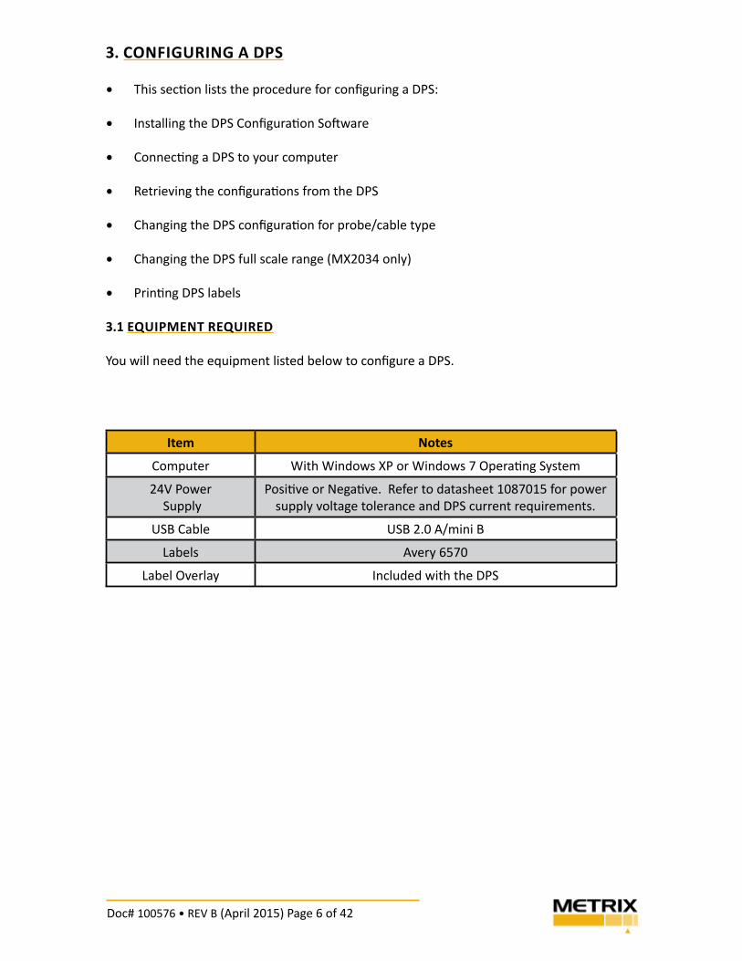
3.1 EQUIPMENT REQUIRED
You will need the equipment listed below to confi gure a DPS.
Item Notes
Computer With Windows XP or Windows 7 Opera! ng System
24V Power
Supply
Posi! ve or Nega! ve. Refer to datasheet 1087015 for power
supply voltage tolerance and DPS current requirements.
USB Cable USB 2.0 A/mini B
Labels Avery 6570
Label Overlay Included with the DPS
Doc# 100576 • REV B (April 2015) Page 7 of 42
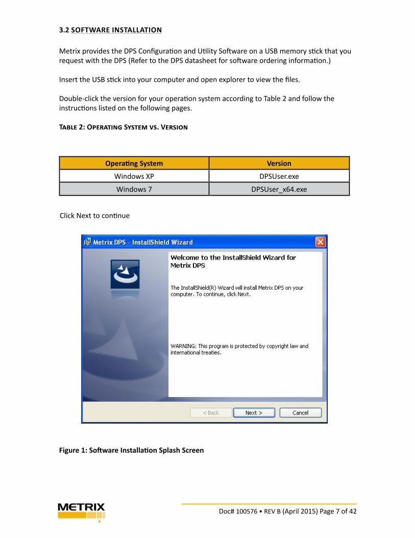
3.2 SOFTWARE INSTALLATION
Metrix provides the DPS Confi gura" on and U" lity So$ ware on a USB memory s" ck that you
request with the DPS (Refer to the DPS datasheet for so$ ware ordering informa" on.)
Insert the USB s" ck into your computer and open explorer to view the fi les.
Double-click the version for your opera" on system according to Table 2 and follow the
instruc" ons listed on the following pages.
T!"#$ 2: O%$&!'()* S+,'$- /,. V$&,(0)
Opera1 ng System Version
Windows XP DPSUser.exe
Windows 7 DPSUser_x64.exe
Click Next to con" nue
Figure 1: So5 ware Installa1 on Splash Screen

Doc# 100576 • REV B (April 2015) Page 8 of 42
Figure 2 shows the end user license agreement. Click ‘Accept” to con! nue
Figure 2: License Agreement
Figure 3: Installa� on Screen
Click Install to begin the installa! on
Doc# 100576 • REV B (April 2015) Page 9 of 42
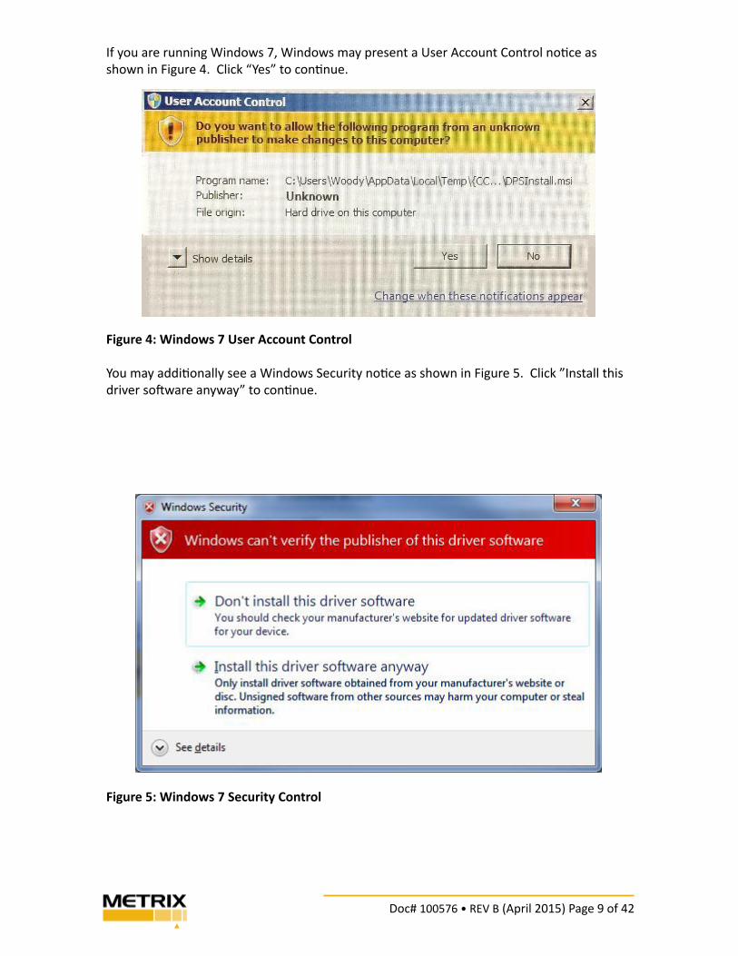
If you are running Windows 7, Windows may present a User Account Control no! ce as
shown in Figure 4. Click “Yes” to con! nue.
Figure 4: Windows 7 User Account Control
You may addi! onally see a Windows Security no! ce as shown in Figure 5. Click ”Install this
driver so" ware anyway” to con! nue.
Figure 5: Windows 7 Security Control
Doc# 100576 • REV B (April 2015) Page 10 of 42
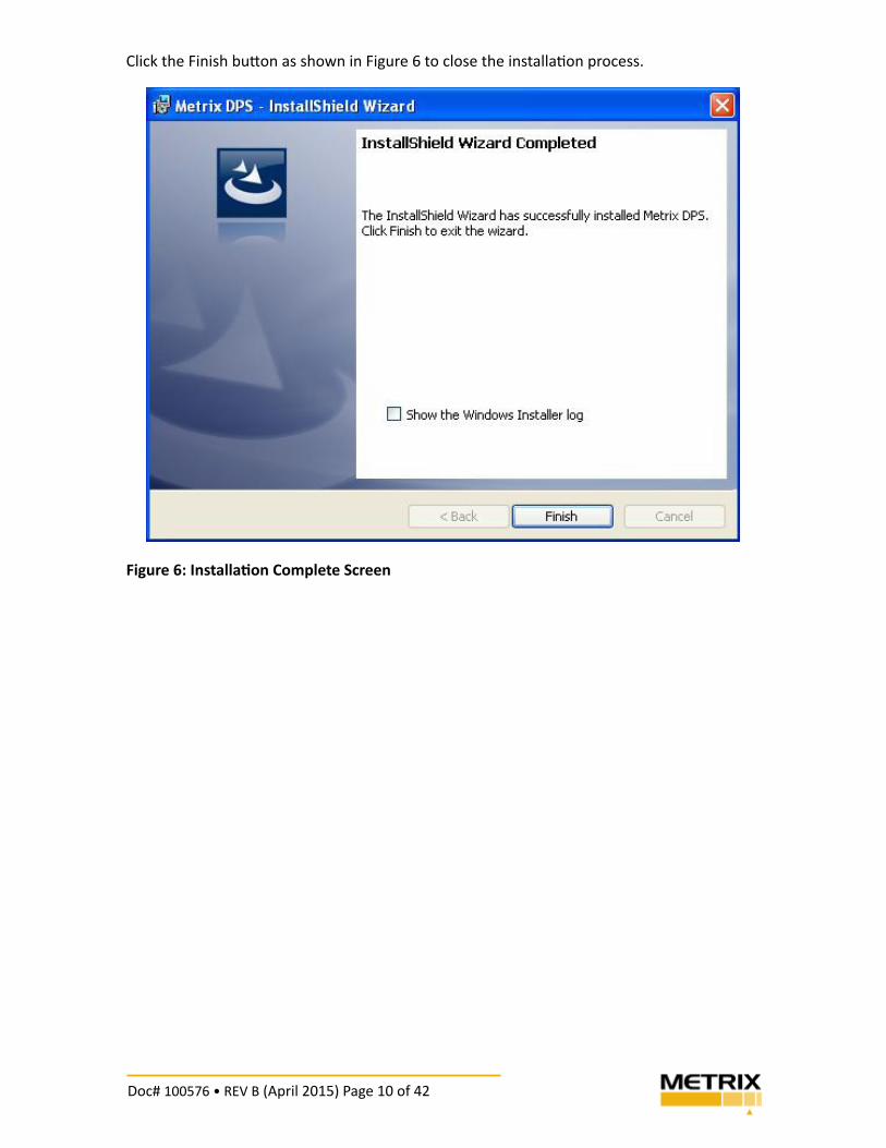
Click the Finish bu! on as shown in Figure 6 to close the installa" on process.
Figure 6: Installa� on Complete Screen
Doc# 100576 • REV B (April 2015) Page 11 of 42
3.3 CONNECTING THE DPS TO A COMPUTER
Follow these steps to access the DPS USB connector for connec! on to a computer.
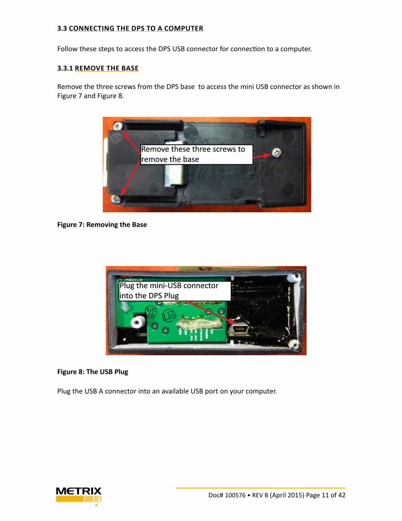
3.3.1 REMOVE THE BASE
Remove the three screws from the DPS base to access the mini USB connector as shown in
Figure 7 and Figure 8.
Figure 7: Removing the Base
Figure 8: The USB Plug
Plug the USB A connector into an available USB port on your computer.
Remove these three screws to
remove the base
Plug the mini-USB connector
into the DPS Plug
Doc# 100576 • REV B (April 2015) Page 12 of 42
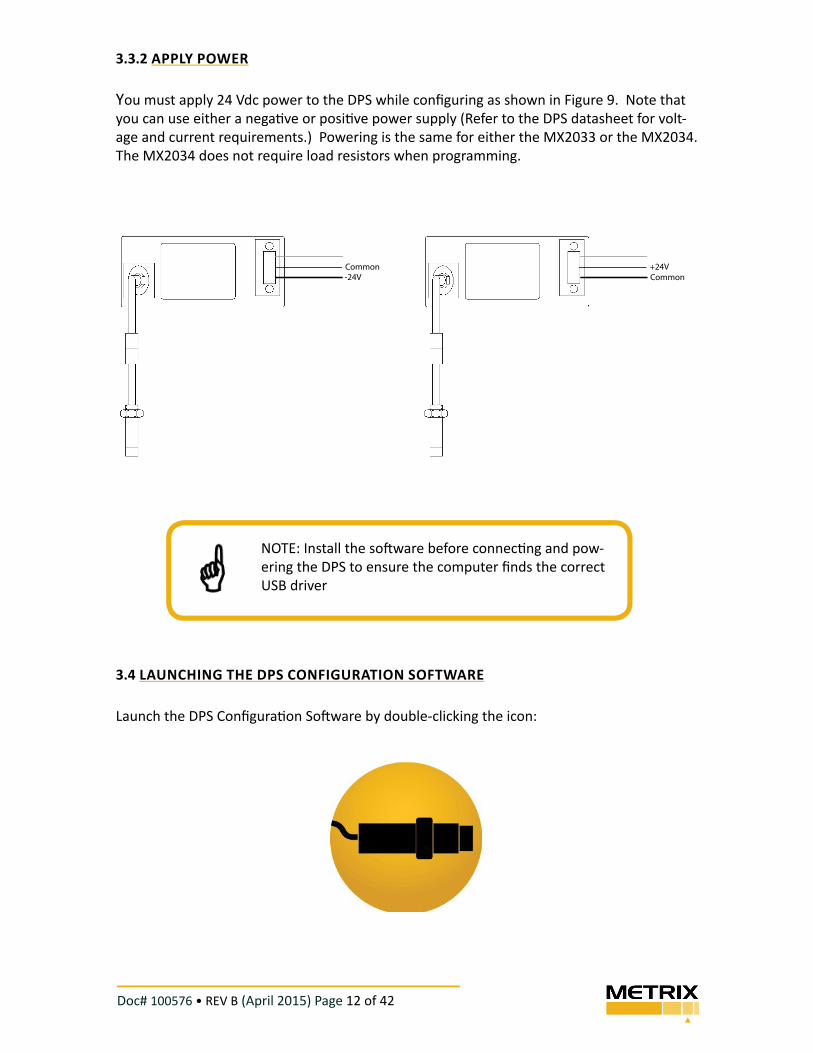
3.3.2 APPLY POWER
You must apply 24 Vdc power to the DPS while confi guring as shown in Figure 9. Note that
you can use either a nega" ve or posi" ve power supply (Refer to the DPS datasheet for volt-
age and current requirements.) Powering is the same for either the MX2033 or the MX2034.
The MX2034 does not require load resistors when programming.
Figure 9: Powering the DPS
3.4 LAUNCHING THE DPS CONFIGURATION SOFTWARE
Launch the DPS Confi gura" on So$ ware by double-clicking the icon:
NOTE: Install the so$ ware before connec" ng and pow-
ering the DPS to ensure the computer fi nds the correct
USB driver
Common
-24V Common
+24V
Doc# 100576 • REV B (April 2015) Page 13 of 42
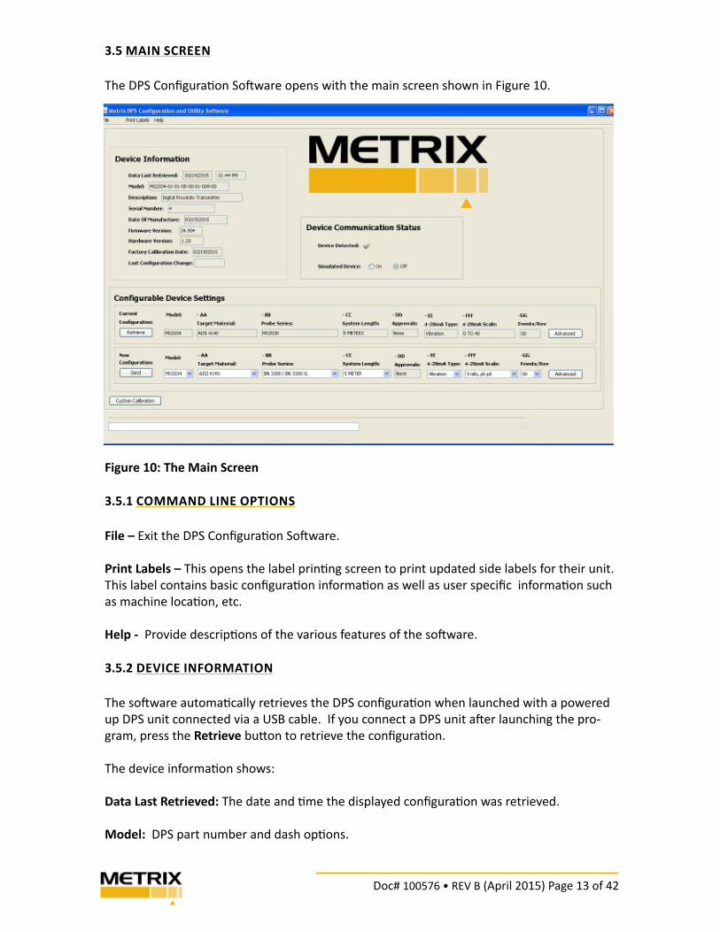
3.5 MAIN SCREEN
The DPS Confi gura" on So$ ware opens with the main screen shown in Figure 10.
Figure 10: The Main Screen
3.5.1 COMMAND LINE OPTIONS
File – Exit the DPS Confi gura" on So$ ware.
Print Labels – This opens the label prin" ng screen to print updated side labels for their unit.
This label contains basic confi gura" on informa" on as well as user specifi c informa" on such
as machine loca" on, etc.
Help - Provide descrip" ons of the various features of the so$ ware.
3.5.2 DEVICE INFORMATION
The so$ ware automa" cally retrieves the DPS confi gura" on when launched with a powered
up DPS unit connected via a USB cable. If you connect a DPS unit a$ er launching the pro-
gram, press the Retrieve bu% on to retrieve the confi gura" on.
The device informa" on shows:
Data Last Retrieved: The date and " me the displayed confi gura" on was retrieved.
Model: DPS part number and dash op" ons.
Doc# 100576 • REV B (April 2015) Page 14 of 42
Descrip� on: Digital Proximity Driver (MX2033) or Digital Proximity Transmi! er (MX2034)
Serial Number: Device serial number
Date of Manufacture: Date the device was manufactured.
Firmware Version: Firmware model and revision number
Hardware Version: Hardware major.minor revision number
Factory Calibra� on Date: Date of the last " me Metrix calibrated the device
Last Confi gura� on Change: Date the confi gura" on was last changed.
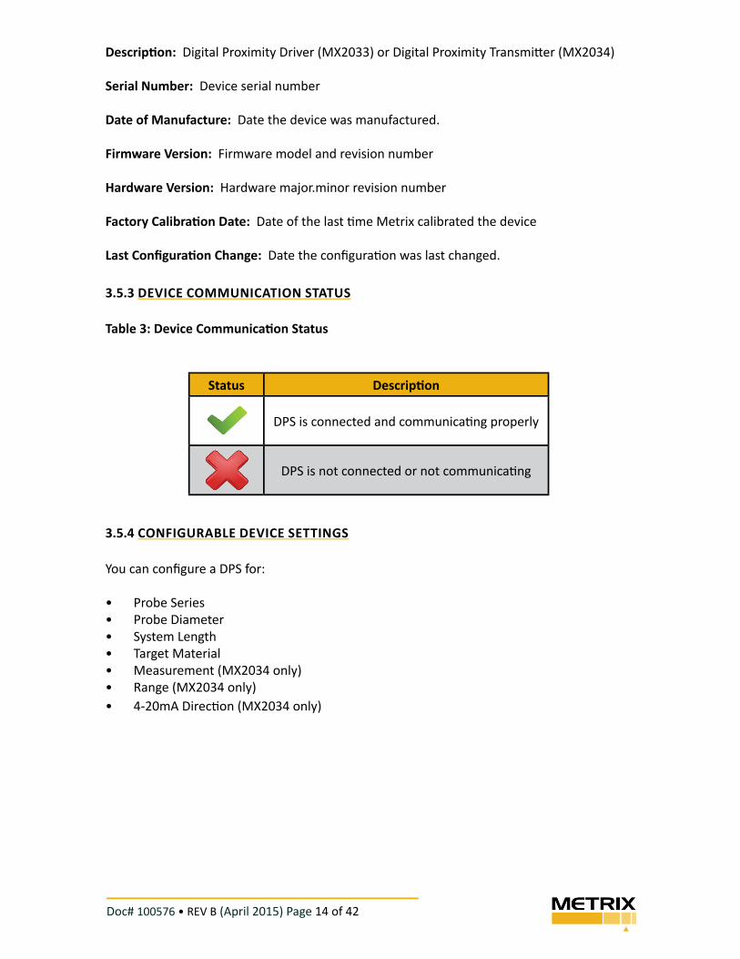
3.5.3 DEVICE COMMUNICATION STATUS
Table 3: Device Communica� on Status
3.5.4 CONFIGURABLE DEVICE SETTINGS
You can confi gure a DPS for:
• Probe Series
• Probe Diameter
• System Length
• Target Material
• Measurement (MX2034 only)
• Range (MX2034 only)
• 4-20mA Direc" on (MX2034 only)
Status Descrip� on
DPS is connected and communica" ng properly
DPS is not connected or not communica" ng
Doc# 100576 • REV B (April 2015) Page 15 of 42
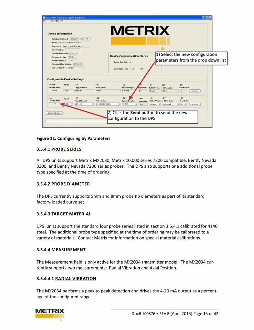
Figure 11: Confi guring by Parameters
3.5.4.1 PROBE SERIES
All DPS units support Metrix MX2030, Metrix 10,000 series 7200 compa! ble, Bently Nevada
3300, and Bently Nevada 7200 series probes. The DPS also supports one addi! onal probe
type specifi ed at the ! me of ordering.
3.5.4.2 PROBE DIAMETER
The DPS currently supports 5mm and 8mm probe ! p diameters as part of its standard
factory-loaded curve set.
3.5.4.3 TARGET MATERIAL
DPS units support the standard four probe series listed in sec! on 3.5.4.1 calibrated for 4140
steel. The addi! onal probe type specifi ed at the ! me of ordering may be calibrated to a
variety of materials. Contact Metrix for informa! on on special material calibra! ons.
3.5.4.4 MEASUREMENT
The Measurement fi eld is only ac! ve for the MX2034 transmi$ er model. The MX2034 cur-
rently supports two measurements: Radial Vibra! on and Axial Posi! on.
3.5.4.4.1 RADIAL VIBRATION
The MX2034 performs a peak to peak detec! on and drives the 4-20 mA output as a percent-
age of the confi gured range.
1) Select the new confi gura! on
parameters from the drop down list
2) Click the Send bu$ on to send the new
confi gura! on to the DPS
Doc# 100576 • REV B (April 2015) Page 16 of 42
3.5.4.4.2 AXIAL POSITION
The MX2034 low pass fi lters the measured signal and outputs the axial posi" on as a percent-
age of the confi gured range.
3.5.4.5 RANGE
The Range choices are diff erent for Radial Vibra" on and Axial Posi" on measurements.
3.5.4.6 4!20mA DIRECTION
The MX2034 allows confi gura" on of upscale or downscale for the 4-20mA output. Upscale
means that for the range selected in 3.5.4.5, 4mA corresponds to bo% om of scale and 20mA
corresponds to top of scale; downscale reverses these conven" ons and means that 20mA
corresponds to bo% om of scale and 4mA corresponds to top of scale.
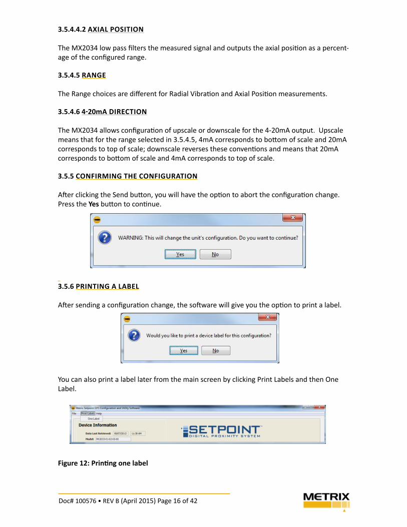
3.5.5 CONFIRMING THE CONFIGURATION
A& er clicking the Send bu% on, you will have the op" on to abort the confi gura" on change.
Press the Yes bu% on to con" nue.
3.5.6 PRINTING A LABEL
A& er sending a confi gura" on change, the so& ware will give you the op" on to print a label.
You can also print a label later from the main screen by clicking Print Labels and then One
Label.
Figure 12: Prin" ng one label
Doc# 100576 • REV B (April 2015) Page 17 of 42
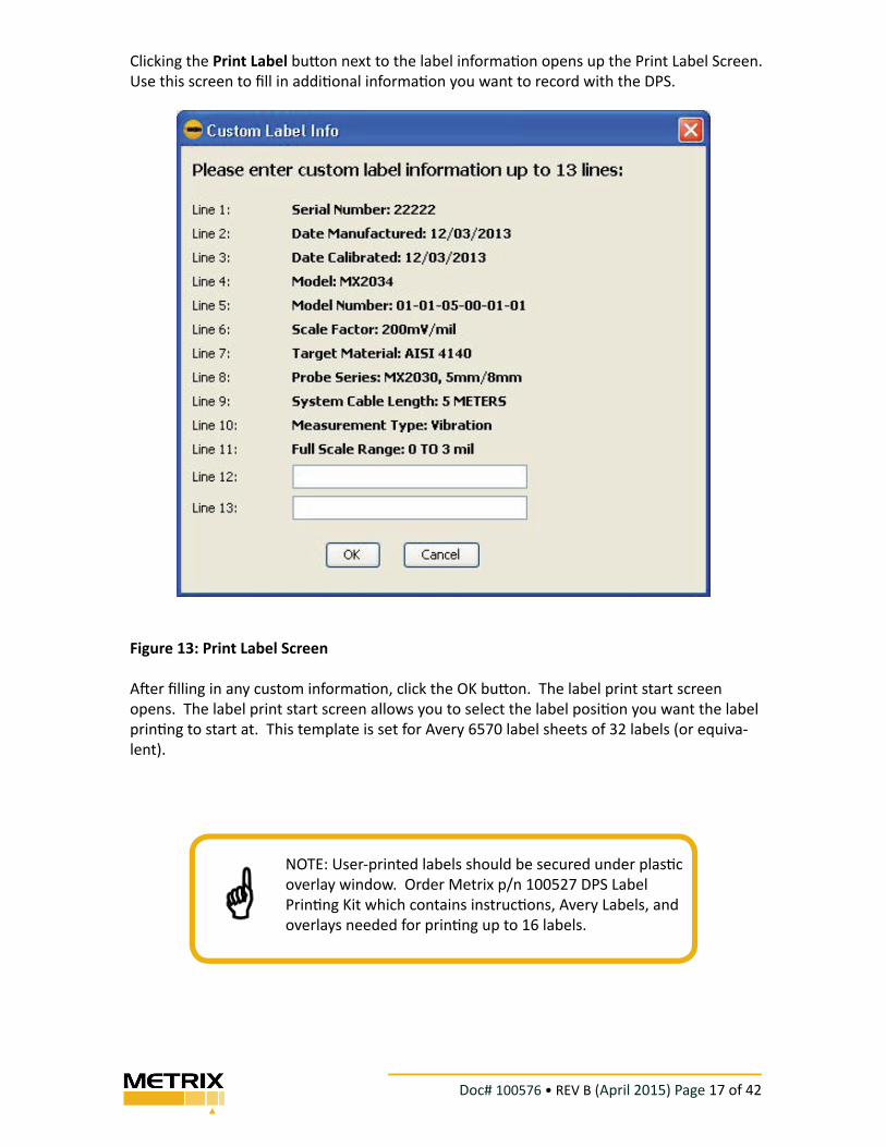
Clicking the Print Label bu! on next to the label informa" on opens up the Print Label Screen.
Use this screen to fi ll in addi" onal informa" on you want to record with the DPS.
Figure 13: Print Label Screen
A% er fi lling in any custom informa" on, click the OK bu! on. The label print start screen
opens. The label print start screen allows you to select the label posi" on you want the label
prin" ng to start at. This template is set for Avery 6570 label sheets of 32 labels (or equiva-
lent).
NOTE: User-printed labels should be secured under plas" c
overlay window. Order Metrix p/n 100527 DPS Label
Prin" ng Kit which contains instruc" ons, Avery Labels, and
overlays needed for prin" ng up to 16 labels.
Doc# 100576 • REV B (April 2015) Page 18 of 42
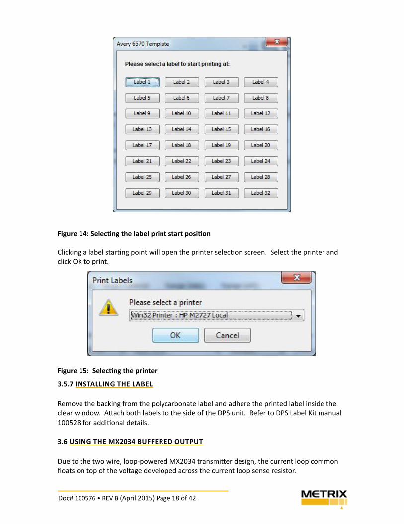
Figure 14: Selec� ng the label print start posi� on
Clicking a label star! ng point will open the printer selec! on screen. Select the printer and
click OK to print.
Figure 15: Selec� ng the printer
3.5.7 INSTALLING THE LABEL
Remove the backing from the polycarbonate label and adhere the printed label inside the
clear window. A" ach both labels to the side of the DPS unit. Refer to DPS Label Kit manual
100528 for addi! onal details.
3.6 USING THE MX2034 BUFFERED OUTPUT
Due to the two wire, loop-powered MX2034 transmi" er design, the current loop common
fl oats on top of the voltage developed across the current loop sense resistor.
Doc# 100576 • REV B (April 2015) Page 19 of 42
The buff ered output common is protected against ground loop currents aff ec" ng the current
loop output with a 10kΩ resistance between the buff ered output common and the loop
common.
Metrix recommends using a ground isolated instrument or signal isolator. The meter, oscil-
loscope or analyzer used to measure the gap voltage or to observe the vibra" on signal
(DYNAMIC OUTPUT) must have an input impedance of one megohm or greater.
The scale factor of the output signal is 200 mV/ mil.
Metrix recommends a maximum cable length of 15 % (5 m) when connec" ng to the buff ered
output due to noise suscep" bility caused by the high input and output impedances.
4. VERIFICATION AND CALIBRATION
This sec" on describes the steps to verify proper DPS opera" on and to custom calibrate your
DPS to your specifi c probe and cable.
CAUTION: When using the MX2034 BNC connector, exer-
cise special care to prevent ground loops that could alter
the 4-20mA output, resul" ng in spurious alarms or ma-
chine trips. Such ground loops can occur when connec" ng
to grounded test equipment or mul" ple input test equip-
ment. Metrix recommends use only with ungrounded test
equipment, such as ba' ery-powered portable meters,
or grounded test equipment with diff eren" al inputs (i.e.,
neither side of input connec" on is " ed to ground). Also,
cable lengths between the BNC connector and test equip-
ment should be kept suitably short (5m or less) to prevent
unwanted noise.
NOTE: The DPS requires the probe and extension cables be
from the confi gured probe series, combine to the confi g-
ured system length, and view the confi gured target mate-
rial in order to meet system range and accuracy
Doc# 100576 • REV B (April 2015) Page 20 of 42
4.1 SCALE FACTOR VERIFICATION
Follow these steps in this sec! on to verify the voltage output scale factor. The basic proce-
dure is:
Obtain the correct target material
Assemble the test instruments and equipment
Electrically zero the probe
Measure the output voltage in fi xed gap increments
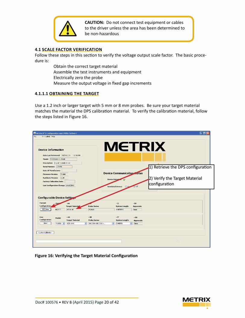
4.1.1.1 OBTAINING THE TARGET
Use a 1.2 inch or larger target with 5 mm or 8 mm probes. Be sure your target material
matches the material the DPS calibra! on material. To verify the calibra! on material, follow
the steps listed in Figure 16.
Figure 16: Verifying the Target Material Confi gura" on
CAUTION: Do not connect test equipment or cables
to the driver unless the area has been determined to
be non-hazardous
1) Retrieve the DPS confi gura! on
2) Verify the Target Material
confi gura! on
Doc# 100576 • REV B (April 2015) Page 21 of 42
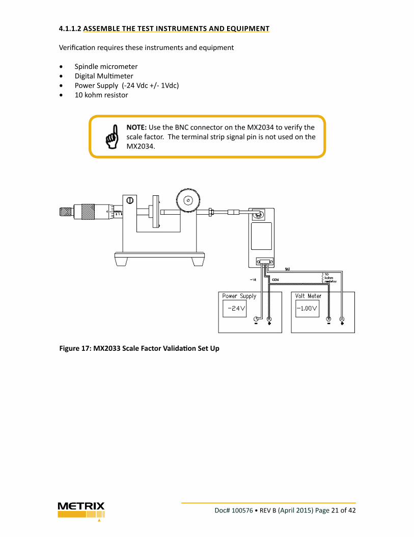
4.1.1.2 ASSEMBLE THE TEST INSTRUMENTS AND EQUIPMENT
Verifi ca" on requires these instruments and equipment
• Spindle micrometer
• Digital Mul" meter
• Power Supply (-24 Vdc +/- 1Vdc)
• 10 kohm resistor
Figure 17: MX2033 Scale Factor Valida! on Set Up
NOTE: Use the BNC connector on the MX2034 to verify the
scale factor. The terminal strip signal pin is not used on the
MX2034.
Doc# 100576 • REV B (April 2015) Page 22 of 42
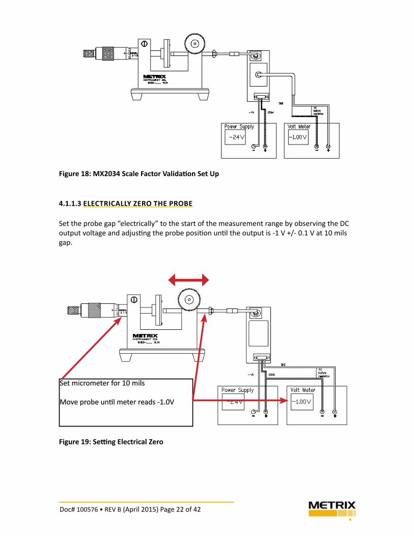
Figure 18: MX2034 Scale Factor Valida� on Set Up
4.1.1.3 ELECTRICALLY ZERO THE PROBE
Set the probe gap “electrically” to the start of the measurement range by observing the DC
output voltage and adjus! ng the probe posi! on un! l the output is -1 V +/- 0.1 V at 10 mils
gap.
Figure 19: Se! ng Electrical Zero
Set micrometer for 10 mils
Move probe un! l meter reads -1.0V
Doc# 100576 • REV B (April 2015) Page 23 of 42
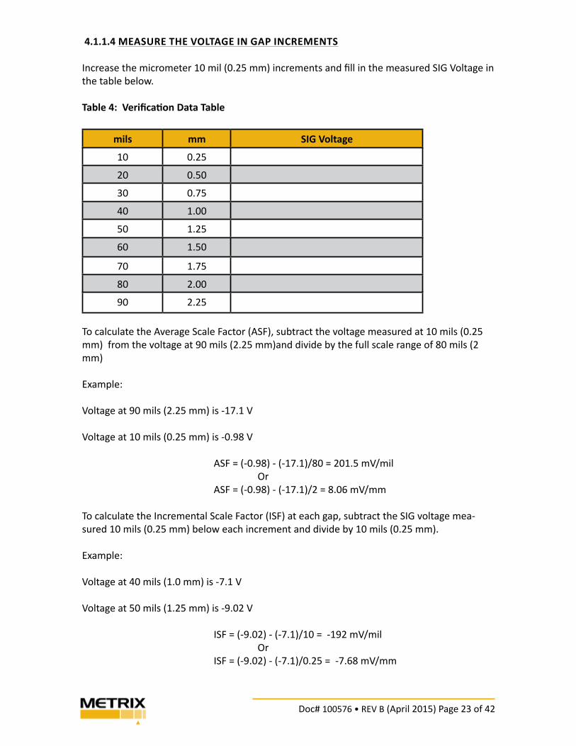
4.1.1.4 MEASURE THE VOLTAGE IN GAP INCREMENTS
Increase the micrometer 10 mil (0.25 mm) increments and fi ll in the measured SIG Voltage in
the table below.
Table 4: Verifi ca" on Data Table
mils mm SIG Voltage
10 0.25
20 0.50
30 0.75
40 1.00
50 1.25
60 1.50
70 1.75
80 2.00
90 2.25
To calculate the Average Scale Factor (ASF), subtract the voltage measured at 10 mils (0.25
mm) from the voltage at 90 mils (2.25 mm)and divide by the full scale range of 80 mils (2
mm)
Example:
Voltage at 90 mils (2.25 mm) is -17.1 V
Voltage at 10 mils (0.25 mm) is -0.98 V
ASF = (-0.98) - (-17.1)/80 = 201.5 mV/mil
Or
ASF = (-0.98) - (-17.1)/2 = 8.06 mV/mm
To calculate the Incremental Scale Factor (ISF) at each gap, subtract the SIG voltage mea-
sured 10 mils (0.25 mm) below each increment and divide by 10 mils (0.25 mm).
Example:
Voltage at 40 mils (1.0 mm) is -7.1 V
Voltage at 50 mils (1.25 mm) is -9.02 V
ISF = (-9.02) - (-7.1)/10 = -192 mV/mil
Or
ISF = (-9.02) - (-7.1)/0.25 = -7.68 mV/mm
Doc# 100576 • REV B (April 2015) Page 24 of 42
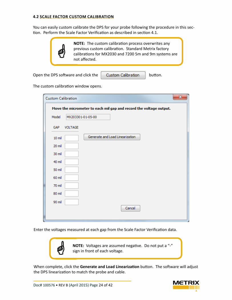
4.2 SCALE FACTOR CUSTOM CALIBRATION
You can easily custom calibrate the DPS for your probe following the procedure in this sec-
! on. Perform the Scale Factor Verifi ca! on as described in sec! on 4.1.
Open the DPS so$ ware and click the bu% on.
The custom calibra! on window opens.
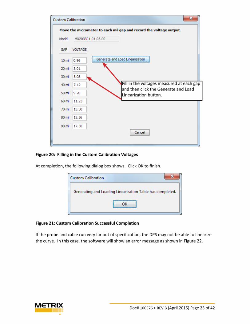
Enter the voltages measured at each gap from the Scale Factor Verifi ca! on data.
When complete, click the Generate and Load Lineariza! on bu% on. The so$ ware will adjust
the DPS lineariza! on to match the probe and cable.
NOTE: The custom calibra! on process overwrites any
previous custom calibra! on. Standard Metrix factory
calibra! ons for MX2030 and 7200 5m and 9m systems are
not aff ected.
plete, click the
NOTE: Voltages are assumed nega! ve. Do not put a “-”
sign in front of each voltage.
Doc# 100576 • REV B (April 2015) Page 25 of 42
Figure 20: Filling in the Custom Calibra� on Voltages
At comple! on, the following dialog box shows. Click OK to fi nish.
Figure 21: Custom Calibra� on Successful Comple� on
If the probe and cable run very far out of specifi ca! on, the DPS may not be able to linearize
the curve. In this case, the so$ ware will show an error message as shown in Figure 22.
Fill in the voltages measured at each gap
and then click the Generate and Load
Lineariza! on bu% on.
Doc# 100576 • REV B (April 2015) Page 26 of 42
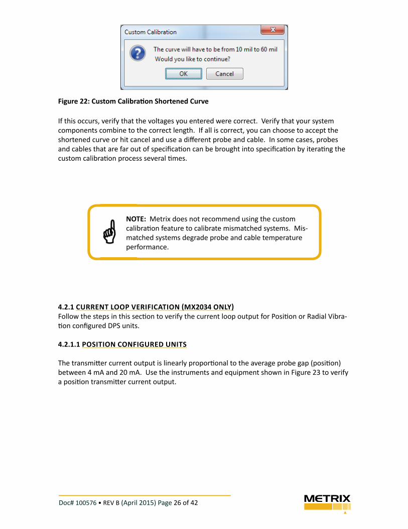
Figure 22: Custom Calibra� on Shortened Curve
If this occurs, verify that the voltages you entered were correct. Verify that your system
components combine to the correct length. If all is correct, you can choose to accept the
shortened curve or hit cancel and use a diff erent probe and cable. In some cases, probes
and cables that are far out of specifi ca$ on can be brought into specifi ca$ on by itera$ ng the
custom calibra$ on process several $ mes.
4.2.1 CURRENT LOOP VERIFICATION !MX2034 ONLY"
Follow the steps in this sec$ on to verify the current loop output for Posi$ on or Radial Vibra-
$ on confi gured DPS units.
4.2.1.1 POSITION CONFIGURED UNITS
The transmi% er current output is linearly propor$ onal to the average probe gap (posi$ on)
between 4 mA and 20 mA. Use the instruments and equipment shown in Figure 23 to verify
a posi$ on transmi% er current output.
NOTE: Metrix does not recommend using the custom
calibra$ on feature to calibrate mismatched systems. Mis-
matched systems degrade probe and cable temperature
performance.
Doc# 100576 • REV B (April 2015) Page 27 of 42
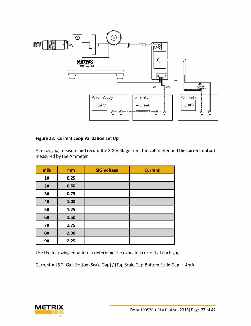
Figure 23: Current Loop Valida� on Set Up
At each gap, measure and record the SIG Voltage from the volt meter and the current output
measured by the Ammeter.
mils mm SIG Voltage Current
10 0.25
20 0.50
30 0.75
40 1.00
50 1.25
60 1.50
70 1.75
80 2.00
90 2.25
Use the following equa! on to determine the expected current at each gap.
Current = 16 * (Gap-Bo" om Scale Gap) / (Top Scale Gap-Bo" om Scale Gap) + 4mA
Doc# 100576 • REV B (April 2015) Page 28 of 42
Example: The confi gured range is 10 to 90 mils and the current gap is 30 mils.
Bo" om Scale Gap = 10 mils
Top Scale Gap = 90 mils
Current = 16 * (30 -10) / (90-10) ) +4mA = 8mA
NOTE: Tolerance is + 0.15 mA.
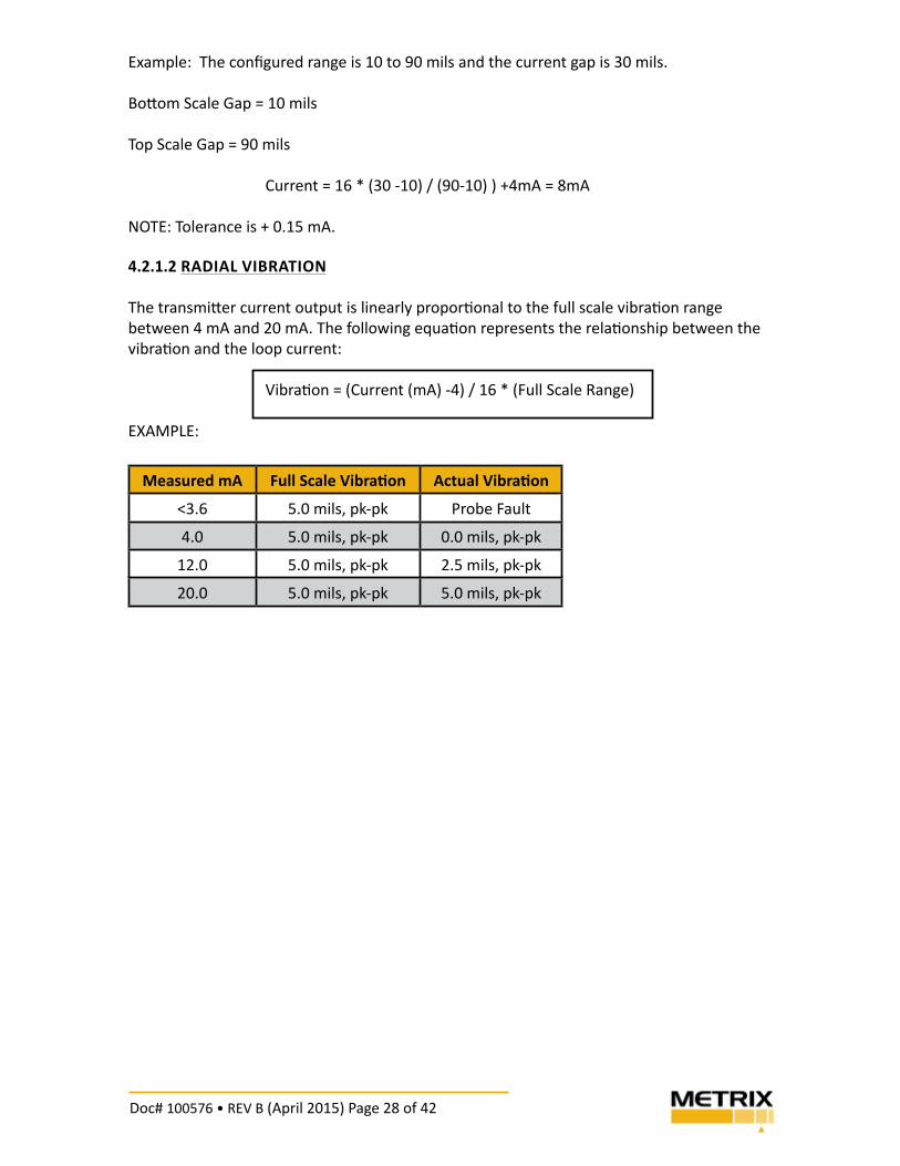
4.2.1.2 RADIAL VIBRATION
The transmi" er current output is linearly propor$ onal to the full scale vibra$ on range
between 4 mA and 20 mA. The following equa$ on represents the rela$ onship between the
vibra$ on and the loop current:
Vibra$ on = (Current (mA) -4) / 16 * (Full Scale Range)
EXAMPLE:
Measured mA Full Scale Vibra! on Actual Vibra! on
<3.6 5.0 mils, pk-pk Probe Fault
4.0 5.0 mils, pk-pk 0.0 mils, pk-pk
12.0 5.0 mils, pk-pk 2.5 mils, pk-pk
20.0 5.0 mils, pk-pk 5.0 mils, pk-pk
Doc# 100576 • REV B (April 2015) Page 29 of 42
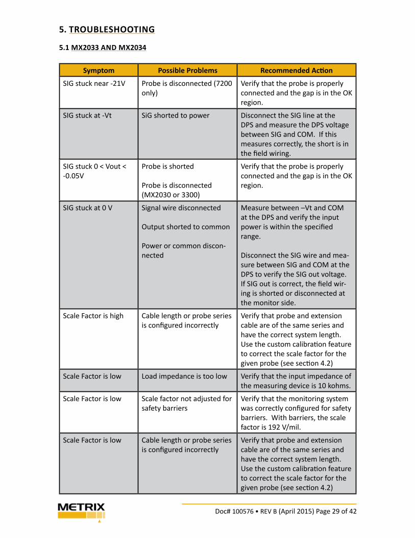
5. TROUBLESHOOTING
5.1 MX2033 AND MX2034
Symptom Possible Problems Recommended Ac! on
SIG stuck near -21V Probe is disconnected (7200
only)
Verify that the probe is properly
connected and the gap is in the OK
region.
SIG stuck at -Vt SiG shorted to power Disconnect the SIG line at the
DPS and measure the DPS voltage
between SIG and COM. If this
measures correctly, the short is in
the fi eld wiring.
SIG stuck 0 < Vout <
-0.05V
Probe is shorted
Probe is disconnected
(MX2030 or 3300)
Verify that the probe is properly
connected and the gap is in the OK
region.
SIG stuck at 0 V Signal wire disconnected
Output shorted to common
Power or common discon-
nected
Measure between –Vt and COM
at the DPS and verify the input
power is within the specifi ed
range.
Disconnect the SIG wire and mea-
sure between SIG and COM at the
DPS to verify the SIG out voltage.
If SIG out is correct, the fi eld wir-
ing is shorted or disconnected at
the monitor side.
Scale Factor is high Cable length or probe series
is confi gured incorrectly
Verify that probe and extension
cable are of the same series and
have the correct system length.
Use the custom calibra" on feature
to correct the scale factor for the
given probe (see sec" on 4.2)
Scale Factor is low Load impedance is too low Verify that the input impedance of
the measuring device is 10 kohms.
Scale Factor is low Scale factor not adjusted for
safety barriers
Verify that the monitoring system
was correctly confi gured for safety
barriers. With barriers, the scale
factor is 192 V/mil.
Scale Factor is low Cable length or probe series
is confi gured incorrectly
Verify that probe and extension
cable are of the same series and
have the correct system length.
Use the custom calibra" on feature
to correct the scale factor for the
given probe (see sec" on 4.2)
Doc# 100576 • REV B (April 2015) Page 30 of 42
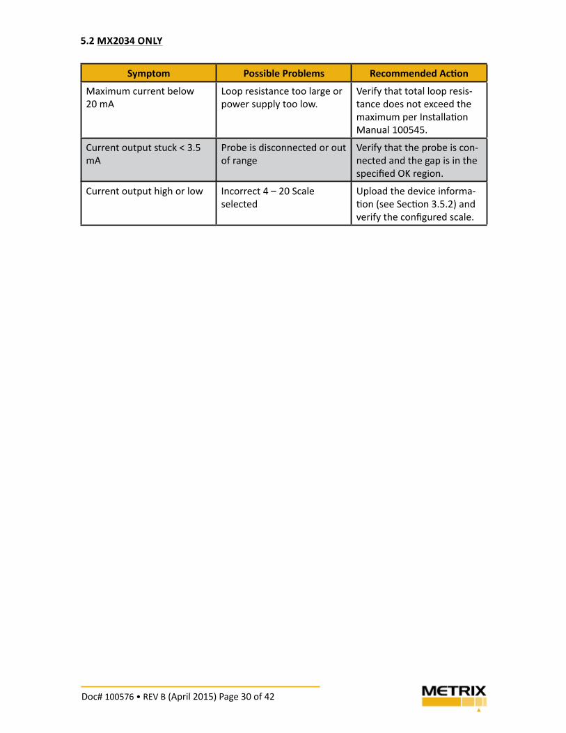
5.2 MX2034 ONLY
Symptom Possible Problems Recommended Ac! on
Maximum current below
20 mA
Loop resistance too large or
power supply too low.
Verify that total loop resis-
tance does not exceed the
maximum per Installa! on
Manual 100545.
Current output stuck < 3.5
mA
Probe is disconnected or out
of range
Verify that the probe is con-
nected and the gap is in the
specifi ed OK region.
Current output high or low Incorrect 4 – 20 Scale
selected
Upload the device informa-
! on (see Sec! on 3.5.2) and
verify the confi gured scale.
Doc# 100576 • REV B (April 2015) Page 31 of 42
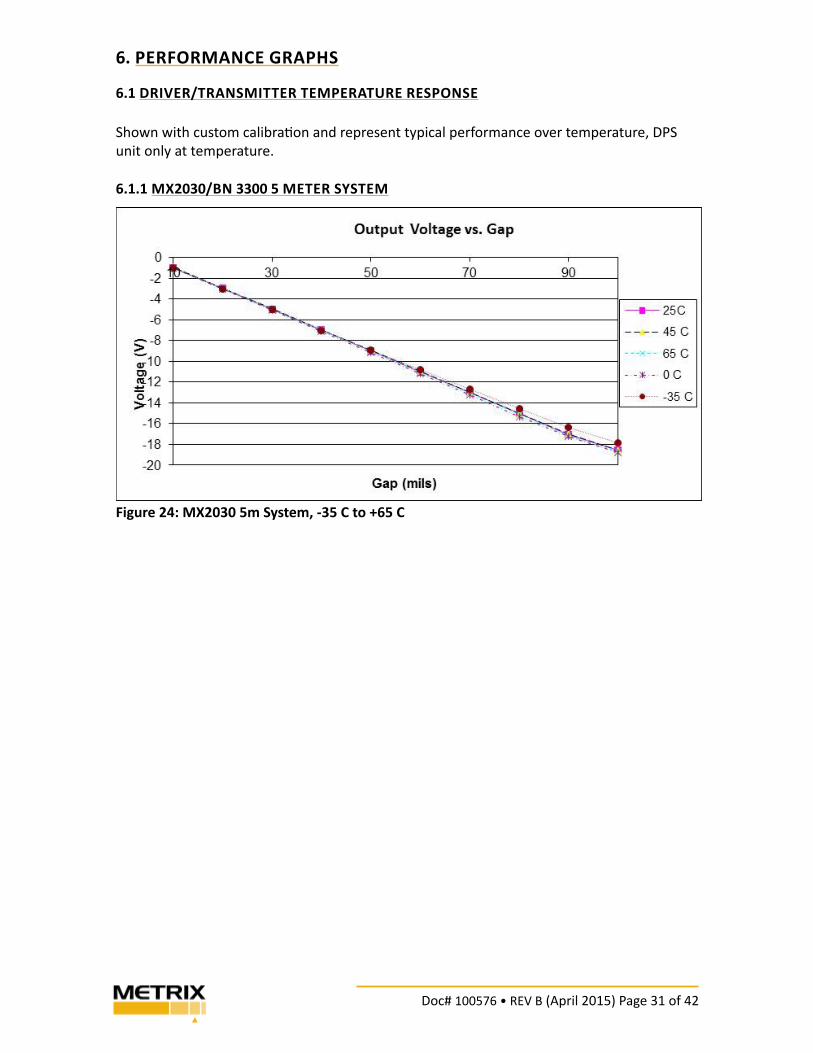
6. PERFORMANCE GRAPHS
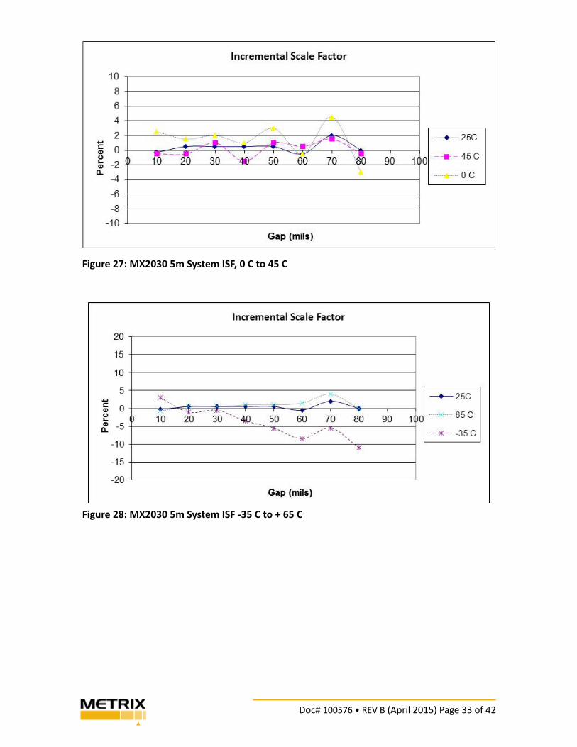
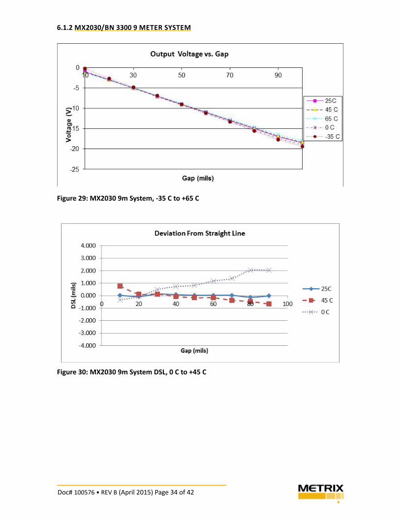
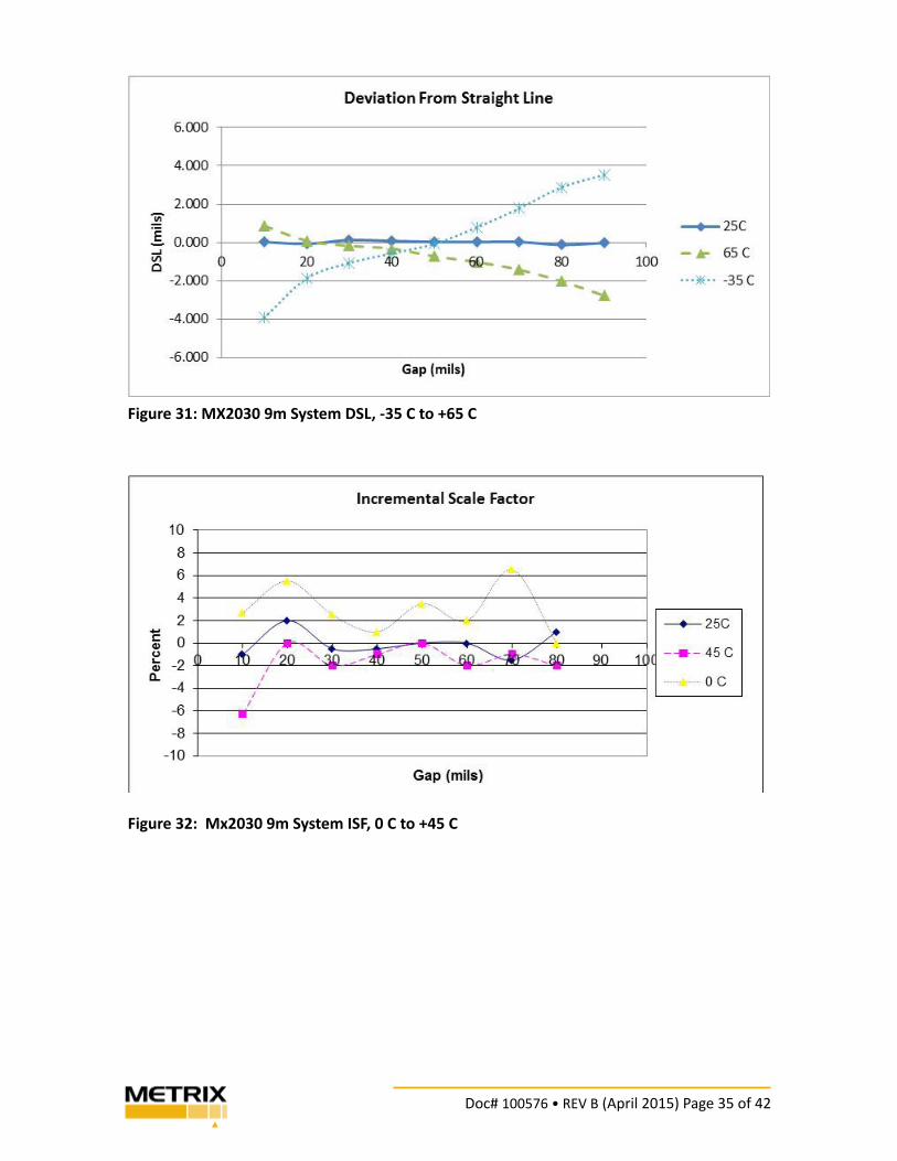
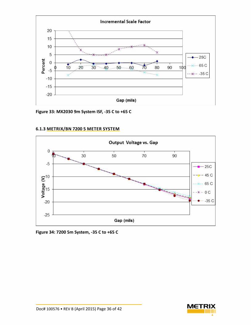
6.1 DRIVER/TRANSMITTER TEMPERATURE RESPONSE
Shown with custom calibra! on and represent typical performance over temperature, DPS
unit only at temperature.
6.1.1 MX2030/BN 3300 5 METER SYSTEM
Figure 24: MX2030 5m System, -35 C to +65 C
Doc# 100576 • REV B (April 2015) Page 32 of 42
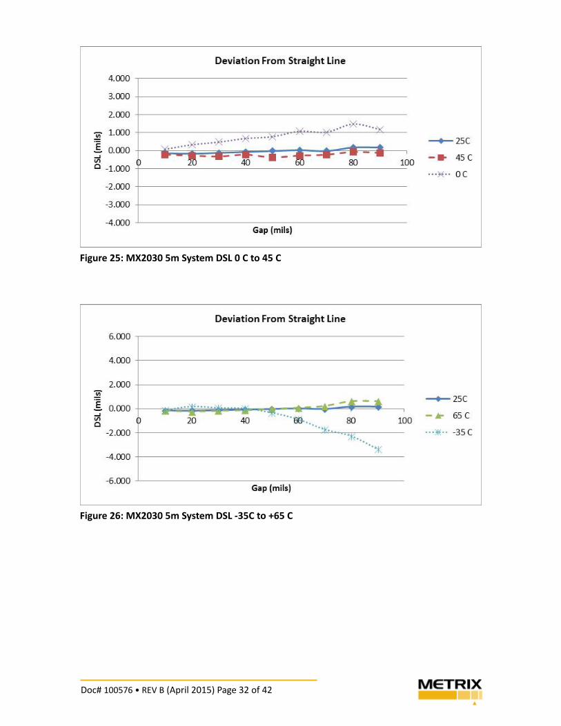
Figure 25: MX2030 5m System DSL 0 C to 45 C
Figure 26: MX2030 5m System DSL -35C to +65 C
Doc# 100576 • REV B (April 2015) Page 33 of 42
Figure 27: MX2030 5m System ISF, 0 C to 45 C
Figure 28: MX2030 5m System ISF -35 C to + 65 C
Doc# 100576 • REV B (April 2015) Page 34 of 42
6.1.2 MX2030/BN 3300 9 METER SYSTEM
Figure 29: MX2030 9m System, -35 C to +65 C
Figure 30: MX2030 9m System DSL, 0 C to +45 C
Doc# 100576 • REV B (April 2015) Page 35 of 42
Figure 31: MX2030 9m System DSL, -35 C to +65 C
Figure 32: Mx2030 9m System ISF, 0 C to +45 C
Doc# 100576 • REV B (April 2015) Page 36 of 42
Figure 33: MX2030 9m System ISF, -35 C to +65 C
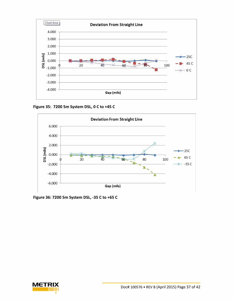
6.1.3 METRIX/BN 7200 5 METER SYSTEM
Figure 34: 7200 5m System, -35 C to +65 C
Doc# 100576 • REV B (April 2015) Page 37 of 42
Figure 35: 7200 5m System DSL, 0 C to +45 C
Figure 36: 7200 5m System DSL, -35 C to +65 C
Doc# 100576 • REV B (April 2015) Page 38 of 42
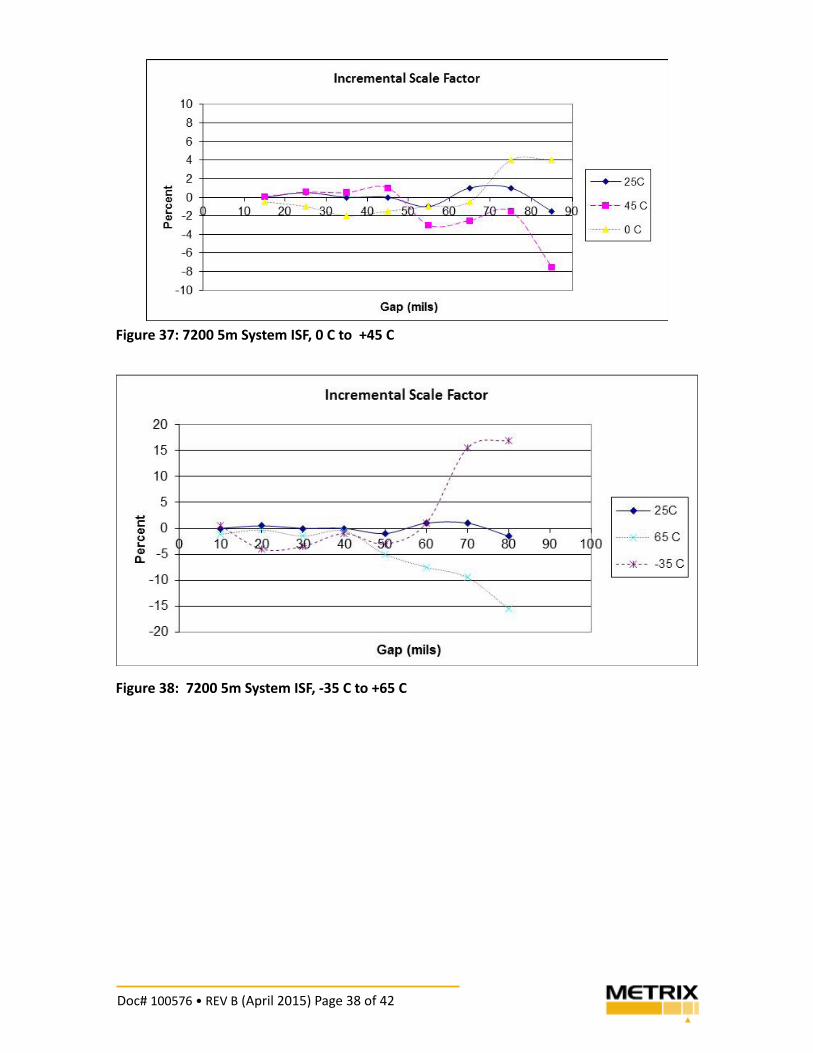
Figure 37: 7200 5m System ISF, 0 C to +45 C
Figure 38: 7200 5m System ISF, -35 C to +65 C
Doc# 100576 • REV B (April 2015) Page 39 of 42
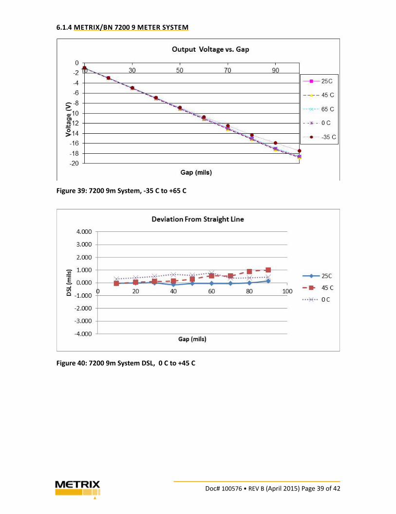
6.1.4 METRIX/BN 7200 9 METER SYSTEM
Figure 39: 7200 9m System, -35 C to +65 C
Figure 40: 7200 9m System DSL, 0 C to +45 C
Doc# 100576 • REV B (April 2015) Page 40 of 42
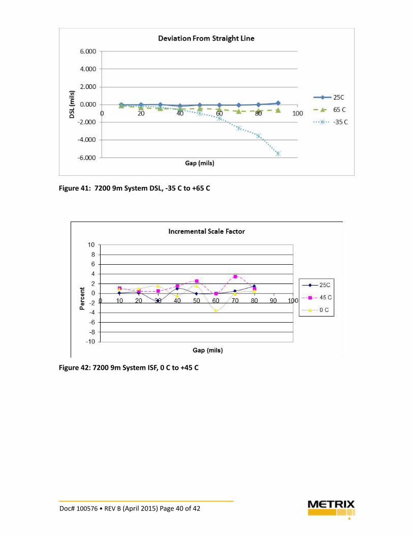
Figure 41: 7200 9m System DSL, -35 C to +65 C
Figure 42: 7200 9m System ISF, 0 C to +45 C
Doc# 100576 • REV B (April 2015) Page 41 of 42
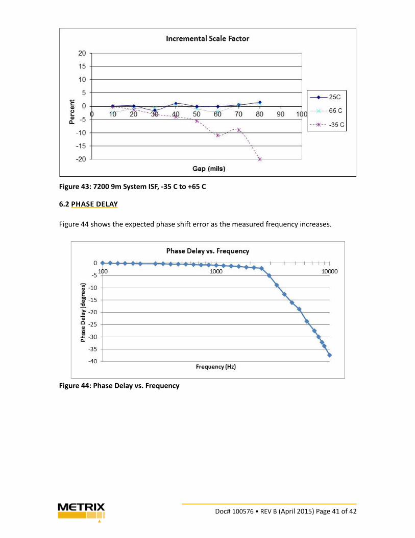
Figure 43: 7200 9m System ISF, -35 C to +65 C
6.2 PHASE DELAY
Figure 44 shows the expected phase shi! error as the measured frequency increases.
Figure 44: Phase Delay vs. Frequency

Doc# 100576 • REV B (April 2015) Page 42 of 42
7. TRADEMARKS AND COPYRIGHTS
All trademarks, service marks, and/or registered trademarks used in this document belong
to Metrix Instrument Company, L.P. except as noted below:
Bently Nevada, RAM, and NSv are marks of the General Electric Company in the United
States and other countries.
Microso! , Excel, Windows, and Outlook and their respec" ve designs are marks of Microso!
Corpora" on in the United States and other countries.
© Copyright 2013, Metrix Instrument Company, L.P. All rights reserved.
info@metrixvibra" on.com
www.metrixvibra" on.com
8824 Fallbrook Dr. Houston, TX 77064, USA
Tel: 1.281.940.1802 • Fax: 1.713.559.9421
A! er Hours (CST) Technical Assistance: 1.713.452.9703