TROVIS 5725-7 Electric Actuator with Process Controller ... · TROVIS 5725-7 Electric Actuator with...
48
Mounting and Operating Instructions EB 5725-7 EN Firmware version 2.03 Edition September 2014 TROVIS 5725-7 Electric Actuator with Process Controller with fail-safe action For heating and cooling applications
Transcript of TROVIS 5725-7 Electric Actuator with Process Controller ... · TROVIS 5725-7 Electric Actuator with...
Mounting and Operating Instructions
EB 5725-7 ENFirmware version 2.03Edition September 2014
TROVIS 5725-7 Electric Actuator with Process Controller with fail-safe action
For heating and cooling applications
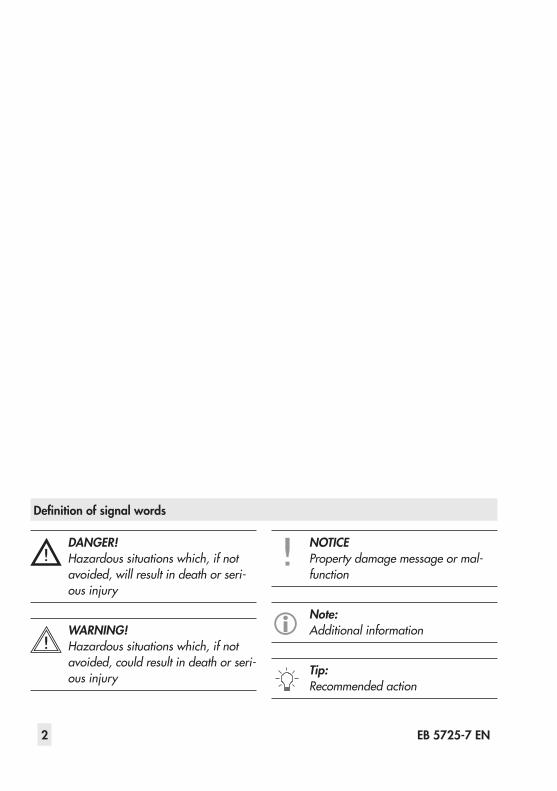
Definition of signal words
DANGER!Hazardous situations which, if not avoided, will result in death or seri-ous injury
WARNING!Hazardous situations which, if not avoided, could result in death or seri-ous injury
NOTICEProperty damage message or mal-function
Note:Additional information
Tip:Recommended action
2 EB 5725-7 EN
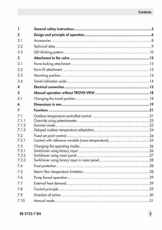
Contents
EB 5725-7 EN 3
1 General safety instructions .............................................................................52 Design and principle of operation ..................................................................62.1 Accessories ...................................................................................................82.2 Technical data ...............................................................................................92.3 LED blinking pattern .....................................................................................103 Attachment to the valve ...............................................................................123.1 Force-locking attachment ..............................................................................123.2 Form-fitattachment ......................................................................................133.3 Mounting position ........................................................................................143.4 Travel indication scale ..................................................................................144 Electrical connection ....................................................................................155 Manual operation without TROVIS-VIEW ......................................................185.1 Changing the travel position .........................................................................186 Dimensions in mm .......................................................................................197 Functions ....................................................................................................217.1 Outdoor-temperature-controlled control .........................................................217.1.1 Override using potentiometer ........................................................................237.1.2 Summer mode .............................................................................................237.1.3 Delayed outdoor temperature adaptation .......................................................247.2 Fixed set point control...................................................................................247.2.1 Control with reference variable (room temperature) .........................................257.3 Changing the operating modes .....................................................................267.3.1 Switchover using binary input .......................................................................267.3.2 Switchover using room panel ........................................................................277.3.3 Switchover using binary input in room panel ..................................................287.4 Frost protection ............................................................................................287.5 Returnflowtemperaturelimitation .................................................................287.6 Pump forced operation .................................................................................297.7 External heat demand ..................................................................................297.8 Control principle ..........................................................................................297.9 Direction of action ........................................................................................307.10 Manual mode ..............................................................................................31
4 EB 5725-7 EN
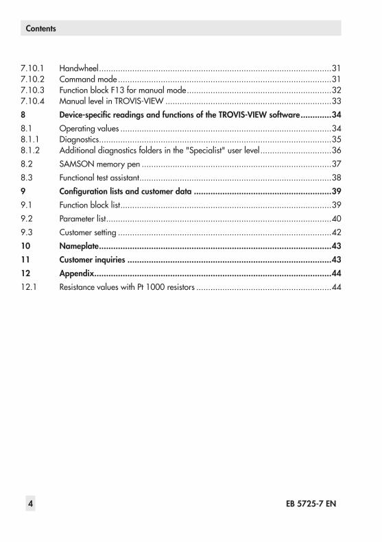
Contents
7.10.1 Handwheel ..................................................................................................317.10.2 Command mode ..........................................................................................317.10.3 Function block F13 for manual mode .............................................................327.10.4 Manual level in TROVIS-VIEW ......................................................................338 Device-specific readings and functions of the TROVIS-VIEW software .............348.1 Operating values .........................................................................................348.1.1 Diagnostics ..................................................................................................358.1.2 Additional diagnostics folders in the "Specialist" user level ..............................368.2 SAMSON memory pen ................................................................................378.3 Functional test assistant .................................................................................389 Configuration lists and customer data ..........................................................399.1 Function block list .........................................................................................399.2 Parameter list ...............................................................................................409.3 Customer setting ..........................................................................................4210 Nameplate ..................................................................................................4311 Customer inquiries ......................................................................................4312 Appendix ....................................................................................................4412.1 Resistance values with Pt 1000 resistors .........................................................44
EB 5725-7 EN 5
General safety instructions
1 General safety instructionsFor your own safety, follow these instructions concerning the mounting, start up, and opera-tion of the device: − The device is to be mounted, started up or operated only by trained and experienced
personnel familiar with the product.According to these mounting and operating instructions, trained personnel refers to indi-viduals who are able to judge the work they are assigned to and recognize possible dan-gers due to their specialized training, their knowledge and experience as well as their knowledge of the applicable standards.
− Any hazards that could be caused in the valve by the process medium and the operating pressure or by moving parts are to be prevented by taking appropriate precautions.
− The device is designed for use in low voltage installations.For wiring and maintenance, you are required to observe the relevant safety regulations.Only use protective equipment that can be protected against unintentional reconnection of the power supply.
− Before wiring the actuator, disconnect it from the power supply.
To avoid damage to any equipment, the following also applies: − Proper shipping and storage are assumed.
Note:Devices with a CE marking fulfill the requirements of the Directives 2004/108/EC and 2006/95/EC.The Declaration of Conformity is available on request.
6 EB 5725-7 EN
Design and principle of operation
2 Design and principle of oper-ation
TheTROVIS 5725-7isacombinationofalinear actuator with fail-safe action and an integrated digital controller.The combination is especially designed for heatingapplicationsaswellasforfixedsetpoint control of heating systems in small to medium-sized buildings. It is particularly suitable for mounting to SAMSON Types 3213,3214,3260,3222,and3226Valves.The digital controllerisconnectedtoaflowsensor on the input side, which can be op-tionallyupgradedbyareturnflow,outdoor
or room sensor.InadditiontothePt 1000input,thedigitalcontroller has a potentiometer input (1000 to 1100 Ωor1000to2000 Ω)tomeasuretheflowtemperature.Thisinputinfluencesthe heating characteristic in the case of out-door-temperature-controlled control and the room temperature set point in the case of fixedsetpointcontrolwithroomtemperatureinfluence.The heating characteristic and set point can bechangedovertheTROVIS-VIEWconfigu-ration software.The actuator contains a reversible synchro-nous motor and a maintenance-free gear.
06
1215
15 126
0
0
6 1215
8 9 1 1.111 1.2
4
3
A AB
B
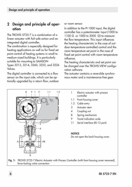
1 Electric actuator with process controller
1.1 Front housing cover1.2 Cable entry3 Actuator stem4 Coupling nut8 Spring mechanism9 Travel indication scale11 Serial interface (RJ-12 port)
NOTICEDo not open the back housing cover.
Fig. 1: TROVIS 5725-7 Electric Actuator with Process Controller (with front housing cover removed), force-locking valve connection
EB 5725-7 EN 7
Design and principle of operation
The force-locking version is connected direct-ly to the valve using a coupling nut (4), whereastheform-fitversionisconnectedtothe valve using a stem connector.The force of the electric motor is transmitted via gearing and crank disk to the actuator stem (3) and, as a result, to the plug stem of the mounted valve.The motor is switched off by torque-depen-dent switches in the end positions or in case of overload.The electric actuator also contains a spring mechanism (8) and an electromagnet. The actuator moves to the fail-safe position when the electromagnet is de-energized. This caus-es the coupling between gear and actuator motor to disengage. The actuator stem is completely extended by the spring mecha-nism. A mounted globe valve is closed (fail-safe position).
NOTICEDo not use the magnet to control the valve position.
Manual override of the actuator stem is pos-sible, after removing the front cover, using a 4 mmAllenkey(seesection 5.1).
TypetestingThe force-locking version of the electric actu-ators with process controller with fail-safe action is tested by the German Technical In-spectorate (TÜV) according to DIN EN 14597.The register number is written on the name-plate.
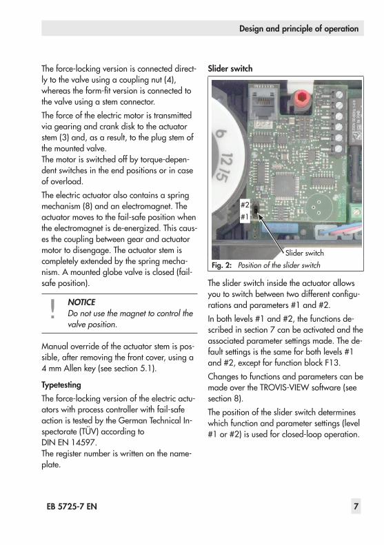
Slider switch
The slider switch inside the actuator allows youtoswitchbetweentwodifferentconfigu-rations and parameters #1 and #2.In both levels #1 and #2, the functions de-scribedinsection 7canbeactivatedandtheassociated parameter settings made. The de-fault settings is the same for both levels #1 and #2, except for function block F13.Changes to functions and parameters can be made over the TROVIS-VIEW software (see section 8).The position of the slider switch determines which function and parameter settings (level #1 or #2) is used for closed-loop operation.
#2#1
Slider switchFig. 2: Position of the slider switch
8 EB 5725-7 EN
Design and principle of operation
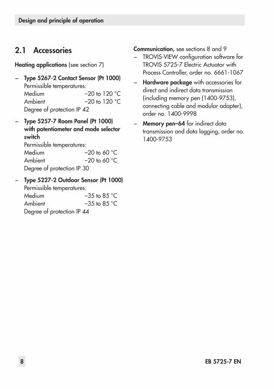
2.1 AccessoriesHeating applications (see section 7)
− Type 5267-2 Contact Sensor (Pt 1000)Permissible temperatures:Medium –20to120 °CAmbient –20to120 °CDegree of protection IP 42
− Type 5257-7 Room Panel (Pt 1000) with potentiometer and mode selector switchPermissible temperatures:Medium –20to60 °CAmbient –20to60 °CDegree of protection IP 30
− Type 5227-2 Outdoor Sensor (Pt 1000)Permissible temperatures:Medium –35to85 °CAmbient –35to85 °CDegree of protection IP 44
Communication,seesections 8and9 − TROVIS-VIEWconfigurationsoftwareforTROVIS 5725-7ElectricActuatorwithProcess Controller, order no. 6661-1067
− Hardware package with accessories for direct and indirect data transmission (including memory pen (1400-9753), connecting cable and modular adapter), order no. 1400-9998
− Memory pen–64 for indirect data transmission and data logging, order no. 1400-9753
EB 5725-7 EN 9
Design and principle of operation
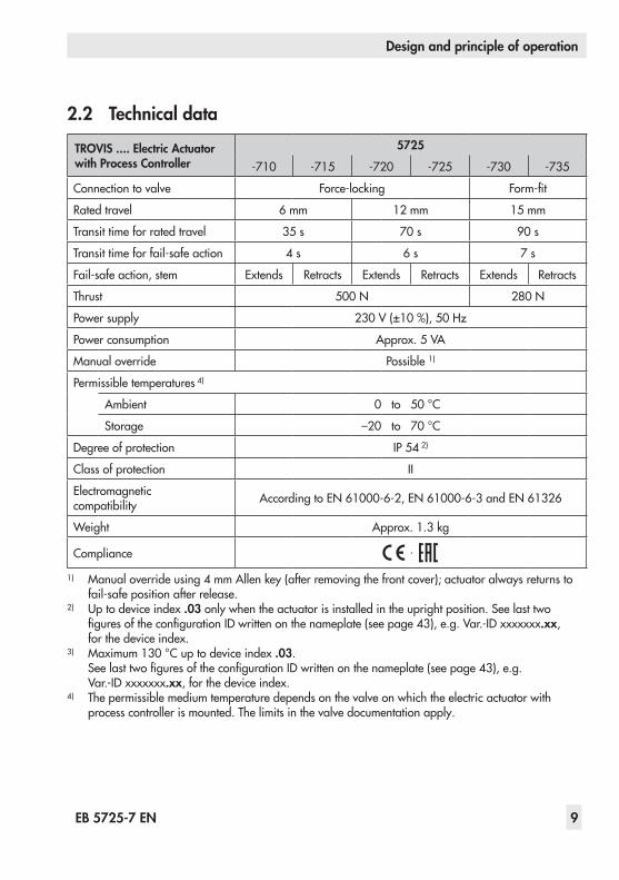
2.2 Technical data
TROVIS .... Electric Actuator with Process Controller
5725
-710 -715 -720 -725 -730 -735
Connection to valve Force-locking Form-fit
Rated travel 6 mm 12 mm 15 mm
Transit time for rated travel 35 s 70 s 90 s
Transit time for fail-safe action 4 s 6 s 7 s
Fail-safe action, stem Extends Retracts Extends Retracts Extends Retracts
Thrust 500 N 280 N
Power supply 230 V(±10 %),50 Hz
Power consumption Approx. 5 VA
Manual override Possible 1)
Permissible temperatures 4)
Ambient 0 to 50 °C
Storage –20 to 70 °C
Degree of protection IP 54 2)
Class of protection II
Electromagnetic compatibility AccordingtoEN 61000-6-2,EN 61000-6-3andEN 61326
Weight Approx.1.3 kg
Compliance ·
1) Manualoverrideusing4 mmAllenkey(afterremovingthefrontcover);actuatoralwaysreturnstofail-safe position after release.
2) Up to device index .03 only when the actuator is installed in the upright position. See last two figuresoftheconfigurationIDwrittenonthenameplate(seepage 43),e.g.Var.-IDxxxxxxx.xx, for the device index.
3) Maximum130 °Cuptodeviceindex.03. SeelasttwofiguresoftheconfigurationIDwrittenonthenameplate(seepage 43),e.g.Var.-ID xxxxxxx.xx, for the device index.
4) The permissible medium temperature depends on the valve on which the electric actuator with process controller is mounted. The limits in the valve documentation apply.

10 EB 5725-7 EN
Design and principle of operation
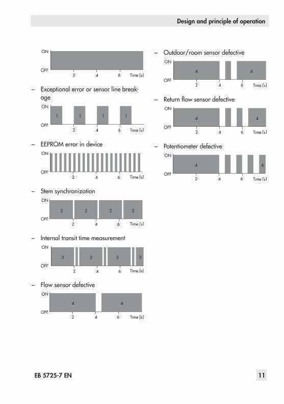
2.3 LED blinking patternThe device has a red and a yellow LED which indicate the operating states of the de-vice.The LEDs are located underneath the front cover on top of the circuit board.
Blinking pattern of the yellow LED
− Device switched off or command modeON
OFFTime [s]
− Device switched on or memory pen action completed.ON
OFFTime [s]
− Activereturnflowtemperaturelimitationor plausibility error in memory pen.ON
OFFTime [s]
− Preparing to read data from memory pen.ON
OFFTime [s]
− Preparing to write data to memory pen.ON
OFFTime [s]
− Preparing data logging.ON
OFFTime [s]
− Data logging in progress.ON
OFFTime [s]
− EEPROM error in memory penON
OFFTime [s]
Blinking pattern of the red LED
− Device switched off, normal operation or command modeON
OFFTime [s]
− Device is starting up or limit switch error
EB 5725-7 EN 11
Design and principle of operation
ON
OFFTime [s]
− Exceptional error or sensor line break-ageON
OFFTime [s]
− EEPROM error in deviceON
OFFTime [s]
− Stem synchronizationON
OFFTime [s]
− Internal transit time measurementON
OFFTime [s]
− Flow sensor defective
OFF
ON
Time [s]
− Outdoor/room sensor defectiveON
OFFTime [s]
− ReturnflowsensordefectiveON
OFFTime [s]
− Potentiometer defectiveON
OFFTime [s]

12 EB 5725-7 EN
Attachment to the valve
3 Attachment to the valveThe actuator is mounted either directly onto the valve (force-locking) or using a stem con-nector(form-fit)dependingonthevalvever-sion used.
3.1 Force-locking attachmentFail-safe action "actuator stem extends"1. Unscrewfrontcoverandplacea4 mm
Allen key on the red actuating shaft.2. Retract the actuator stem: Turn Allen key
counterclockwise only and only as far as the end position which is at the point where the torque-dependent limit contact is activated (switching off the motor).
NOTICETurning the actuator too far will de-stroy it.
3. Hold Allen key in place and fasten valve and actuator together using the coupling nut(tighteningtorque20 Nm).RemoveAllen key and carefully refasten the front cover.
Fail-safe action "actuator stem retracts"Place the actuator on the valve connection and tighten coupling nut (tightening torque 20 Nm).
34
0 0
15
4
16
17
3 Actuator stem
4 Coupling nut
Fig. 3: Force-locking attachment, e.g. to Type 3222 Valve

EB 5725-7 EN 13
Attachment to the valve
3.2 Form-fit attachment1. Place the actuator on the rod-type yoke
(15) and tighten the coupling nut (4) (tighteningtorque20 Nm).
2. Place actuator with rod-type yoke on the valve and tighten the nut (17) (min. tight-eningtorque150 Nm).
3. Pull up the plug stem until it contacts the actuator stem.
4. Position the clamps of the stem connector (16) included in the accessories on the ends of the actuator stem and plug stem and screw tight.
34
0 0
15
4
16
17
4 Coupling nut
15 Yoke
16 Stem connector
17 Nut
Fig. 4: Form-fit attachment, e.g. to Type 3260 Valve, DN 50 and larger

14 EB 5725-7 EN
Attachment to the valve
3.3 Mounting positionThe control valve can be installed in the pipeline in any desired position. However, a suspended mounting position of the actuator isnotpermissible(seeFig. 5).
1) ThedegreeofprotectionIP 54canonlybeachieved up to device index .03 when the actuator is installed in the upright position. SeelasttwofiguresoftheconfigurationIDwrittenonthenameplate(seepage 43),e.g. Var.-ID xxxxxxx.xx, for the device index.
3.4 Travel indication scaleThe travel indication scale has two opposed scales. Which scale is to be used depends onthevalveversion(Fig. 6):
Globe valves and three-way diverting valvesThe driving pin is in position 0 (delivered state).
Three-way mixing valvesRemove scale, turn it and replace it so that the pin is positioned over the appropriate hole (6, 12 or 15) corresponding to the rat-edtravel(6,12or15 mmtravel).
0
06
6
1215
1215
0
15126
Hole for driving pin with three-way mixing valve
Driving pin in position 0, location of scale with globe or three-way diverting valves (de-livered state)
Fig. 6: Travel indication scale
Fig. 5: Mounting position 1)
EB 5725-7 EN 15
Electrical connection
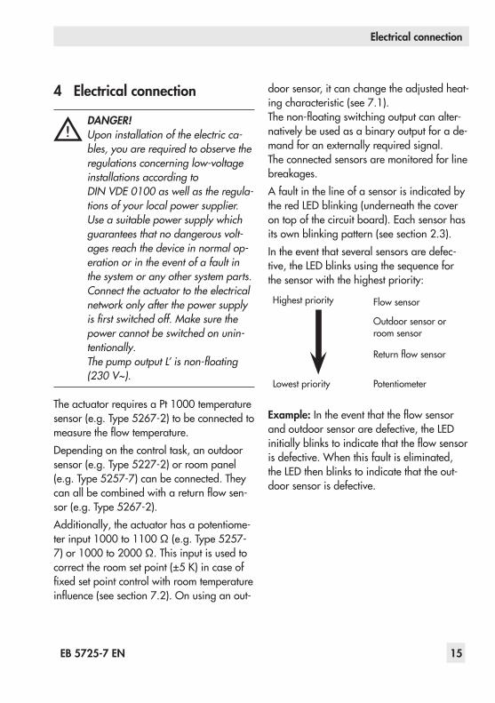
4 Electrical connection
DANGER!Upon installation of the electric ca-bles, you are required to observe the regulations concerning low-voltage installations according to DIN VDE 0100 as well as the regula-tions of your local power supplier.Use a suitable power supply which guarantees that no dangerous volt-ages reach the device in normal op-eration or in the event of a fault in the system or any other system parts.Connect the actuator to the electrical network only after the power supply is first switched off. Make sure the power cannot be switched on unin-tentionally.The pump output L’ is non-floating (230 V~).
TheactuatorrequiresaPt 1000temperaturesensor(e.g.Type 5267-2)tobeconnectedtomeasuretheflowtemperature.Depending on the control task, an outdoor sensor (e.g. Type 5227-2) or room panel (e.g.Type 5257-7) can be connected. They canallbecombinedwithareturnflowsen-sor (e.g. Type 5267-2).Additionally, the actuator has a potentiome-ter input1000to1100 Ω(e.g.Type5257-7)or1000to2000 Ω.Thisinputisusedtocorrecttheroomsetpoint(±5K)incaseoffixedsetpointcontrolwithroomtemperatureinfluence(seesection7.2).Onusinganout-
door sensor, it can change the adjusted heat-ing characteristic (see 7.1).Thenon-floatingswitchingoutputcanalter-natively be used as a binary output for a de-mand for an externally required signal.The connected sensors are monitored for line breakages.A fault in the line of a sensor is indicated by the red LED blinking (underneath the cover on top of the circuit board). Each sensor has itsownblinkingpattern(seesection 2.3).In the event that several sensors are defec-tive, the LED blinks using the sequence for the sensor with the highest priority:
Highest priority Flow sensor
Outdoor sensor or room sensor
Returnflowsensor
Lowest priority Potentiometer
Example:Intheeventthattheflowsensorand outdoor sensor are defective, the LED initiallyblinkstoindicatethattheflowsensoris defective. When this fault is eliminated, the LED then blinks to indicate that the out-door sensor is defective.

16 EB 5725-7 EN
Electrical connection
Perform the electrical connection depending on the application according to one of the followingwiringdiagrams(Fig. 7/Fig. 8).As soon as the actuator is connected to the power supply, the initialization procedure starts.
The actuator stem extends and the red and yellow LEDs are illuminated located under the front cover on top of the circuit board. As soonastheactuatorstemhasreachedthefi-nal position, the red LED is turned off. The yellow LED remains illuminated and indi-cates that the actuator is ready to operate.
Applicationwithflowsensor (VS), returnflowsensor (RüS) and outdoor sensor (AS) and potentiometer functioning as set point adjuster
S3 S4S2S1L' NL
230 V, VS
Pt 1
000
Pt 1
000
Pt 1
000
ASRüS50 Hz
100/
1000
Ω10
00 Ω
NOTICELive wire.
Applicationwithflowsensor(VS),returnflowsensor (RüS) and outdoor sensor (AS) and binary input to switch between operating modes
VS
Pt 1
000
Pt 1
000
Pt 1
000
AS BE1RüS
S3 S4S2S1L' NL
230 V, 50 Hz
NOTICELive wire.
Fig. 7: Electrical connections (part 1)
EB 5725-7 EN 17
Electrical connection
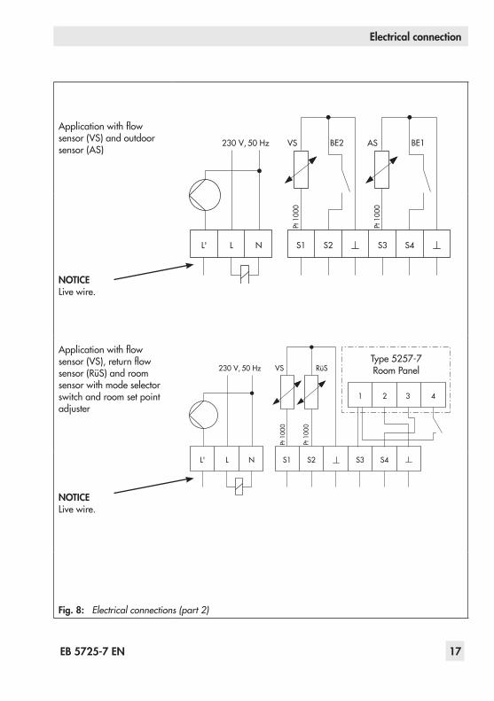
Applicationwithflowsensor (VS) and outdoor sensor (AS)
VS
Pt 1
000
Pt 1
000
AS
S3 S4S2S1L' NL
230 V, 50 Hz BE2 BE1
NOTICELive wire.
Applicationwithflowsensor (VS), returnflowsensor (RüS) and room sensor with mode selector switch and room set point adjuster
1 432
VS
Pt 1
000
Pt 1
000
RüS
S3 S4S2S1L' NL
230 V, 50 Hz
NOTICELive wire.
Fig. 8: Electrical connections (part 2)
Type 5257-7 Room Panel

18 EB 5725-7 EN
Manual operation without TROVIS-VIEW
5 Manual operation without TROVIS-VIEW
5.1 Changing the travel posi-tion
Travel and direction of action can be read off the scale of the travel indicator.
DANGER!Risk of electric shock due to ener-gized device.
1. Unscrewfrontcoverandplacea4 mmAllen key on the red actuating shaft.
2. Turn Allen key counterclockwise only and only as far as the end position which is at the point where the torque-dependent limit switch is activated (switching off the synchronous motor).
NOTICETurning the actuator too far will de-stroy it.
Once the magnet has been released, the spring mechanism pushes the actuator stem back to the fail-safe position.
3. Remove Allen key and carefully refasten the front cover.
Travel indication scale
Handwheel under front cover
Fig. 9: Travel indication scale and handwheel
EB 5725-7 EN 19
Dimensions in mm
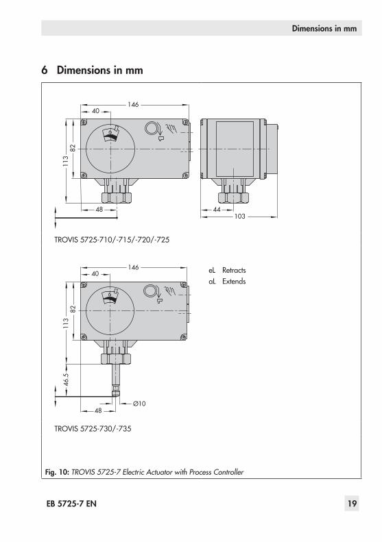
6 Dimensions in mm
146
8211
3
48 44103
40
TROVIS 5725-710/-715/-720/-725
146
8211
346
.5
48Ø10
40 eL RetractsaL Extends
TROVIS 5725-730/-735
Fig. 10: TROVIS 5725-7 Electric Actuator with Process Controller

20 EB 5725-7 EN
Manual operation without TROVIS-VIEW
21
Ø4
5036
756022
28
82 32
20
86
Type 5257-7RoomPanel(Pt 1000)
Continuous day mode (rated operation)Continuous night mode (reduced operation)Off/frost protection
Type 5227-2OutdoorSensor(Pt 1000)Color: RAL 9016
502 32
30
Type 5267-2ContactSensor(Pt 1000)(flowandreturnflowtemperaturemeasurement)
Fig. 11: Accessories for heating control

EB 5725-7 EN 21
Functions
7 FunctionsFunctions and parameters are entered in the TROVIS-VIEW Operator Interface separately for level #1 and level #2 (see section 8).
7.1 Outdoor-temperature-controlled controlWhenoutdoor-temperature-controlledcontrolisused,theflowtemperature(tA) is controlled accordingtotheoutdoortemperature.Theheatingcharacteristicinthecontrollerdefinestheflowtemperaturesetpointasafunctionoftheoutdoortemperature(Fig. 12).Basically,thefollowingruleapplies:adecreaseintheoutdoortemperaturecausestheflowtemperature to increase. By varying the Gradient and Level parameters, the characteristic can be adapted to individual requirements: An increased Gradient causes an increase in flowtemperature,whereasareducedGradientcausesalowerflowtemperature.TheLevel parameter shifts the heating characteristic parallel upwards or downwards.Inreducedoperation,theflowtemperatureisreducedbytheamountsetinFlow temperature set-back in reduced operation.The Max. flow temperature and Min. flow temperatureparameterslimittheflowtemperaturerange. Return flow temperature limitation (see section 7.5) is an exception as it can reduce theflowtemperaturewithoutrestrictiondownto20 °Cflowtemperaturesetpoint.
20
300.2
2.4
2.62.93.2
2.2
2.0
1.8
1.6
1.4
1.21.0
0.8
0.4
0.6
40
50
60
70
80
90
100
110
120
130
tVL [˚C]
-20 [˚C]
tA
-16-12-8-4048121620
tVL Flow temperature
tA Outdoor temperature
Fig. 12: Heating characteristics

22 EB 5725-7 EN
Functions
Functions WE ConfigurationF01 – Control mode 1 F01 - 1F02 – Selecting the reference variable 0 F02 - 0
Parameters WE Value rangeP02 – Flow temperature set-back in reduced operation 15 K 0to50 KP03–Min.flowtemperature 20 °C 0to150 °CP04–Max.flowtemperature 120 °C 0to150 °CP05 – Heating characteristic gradient 1.6 0.2 to 3.2P06 – Heating characteristic level 0 K –30to30 K
Examples for adjusting the characteristic: − Old building, radiator design 90/70: Gradient approx. 1.8 − New building, radiator design 70/55: Gradient approx. 1.4 − New building, radiator design 55/45: Gradient approx. 1.0 − Underfloorheatingdependingonarrangement: Gradientsmallerthan0.5
RüS
UP
VS BE1
VL RL
AS
AS Outdoor sensor UP Circulation pump (heating)RüS Returnflowsensor RL DistrictheatingreturnflowVS Flow sensor VL District heating supply
Fig. 13: Sample application: Outdoor-temperature-controlled flow temperature control with return flow temperature limitation; with binary contact (BI1) to switch between operating modes
EB 5725-7 EN 23
Functions
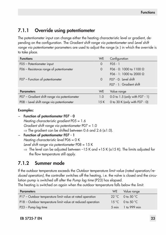
7.1.1 Override using potentiometerThe potentiometer input can change either the heating characteristic level or gradient, de-pendingontheconfiguration.TheGradient shift range via potentiometer and Level shift range via potentiometerparametersareusedtoadjusttherange(±)inwhichtheoverrideisto take place.
Functions WE ConfigurationF05 – Potentiometer input 0 F05 - 1F06 – Resistance range of potentiometer 0 F06 - 0: 1000to1100 Ω
F06 - 1: 1000to2000 ΩF07 – Function of potentiometer
0 F07 - 0: Level shiftF07 - 1: Gradient shift
Parameters WE Value rangeP07 – Gradient shift range via potentiometer 1.0 0.0 to 1.5 (only with F07 - 1)P08 – Level shift range via potentiometer 15 K 0to30 K(onlywithF07-0)
Examples: − Function of potentiometer F07 - 0
Heating characteristic gradient P05 = 1.6Gradient shift range via potentiometer P07 = 1.0⇒Thegradientcanbeshiftedbetween0.6and2.6(±1.0).
− Function of potentiometer F07 - 1Heating characteristic levelP06=0KLevel shift range via potentiometer P08=15K⇒ Thelevelcanbeadjustedbetween–15 Kand+15 K(±15 K).Thelimitsadjustedfor
theflowtemperaturestillapply.
7.1.2 Summer modeIf the outdoor temperature exceeds the Outdoor temperature limit value (rated operation/re-duced operation), the controller switches off the heating, i.e. the valve is closed and the circu-lation pump is switched off after the Pump lag time (P23) has elapsed.The heating is switched on again when the outdoor temperature falls below the limit.
Parameters WE Value rangeP17 – Outdoor temperature limit value at rated operation 22 °C 0to50 °CP18 – Outdoor temperature limit value at reduced operation 15 °C 0to50 °CP23 – Pump lag time 5 min 1to999 min

24 EB 5725-7 EN
Functions
7.1.3 Delayed outdoor temperature adaptationThecalculatedoutdoortemperatureisusedtodeterminetheflowtemperaturesetpoint.Theheat response is delayed when the outdoor temperature either increases or decreases. Iftheoutdoortemperaturevariesby,forexample,12 °Cwithinaveryshortperiodoftime,the calculated outdoor temperature is adapted to the actual outdoor temperature in small steps. Assuming a Delay time of outdoor temperatureof3 °C/h,thelinearadaptationwouldtake t = 12 °C
3 °C/h=4 h.
Note:The delayed outdoor temperature adaptation helps avoid unnecessary overloads of central heating stations in combination with either overheated buildings occurring, for example, due to warm winds, or temporarily insufficient heating due to the outdoor sensor being exposed to direct sunshine.
Functions WE ConfigurationF04 – Delayed outdoor temperature 0 F04 - 1
Parameters WE Value rangeP16 – Delay time for outdoor temperature 3 °C/h 1to6 °C/h
7.2 Fixed set point controlTheflowtemperatureiscontrolledtothefixedvalueinFlowtemperaturesetpoint.Inreducedoperation,theflowsetpointisusedforthecontrolreducedbytheamountinFlow tempera-ture set-back in reduced operation. A connected outdoor sensor does not have any affect on the control.
Functions WE ConfigurationF01 – Control mode 1 F01 - 0
Parameters WE Value rangeP01 – Flow temperature set point 70 °C 0to150 °CP02 – Flow temperature set-back in reduced operation 15 K 0to50 K
Note:The return flow limitation and the potentiometer override are still active when config-ured correspondingly.
EB 5725-7 EN 25
Functions
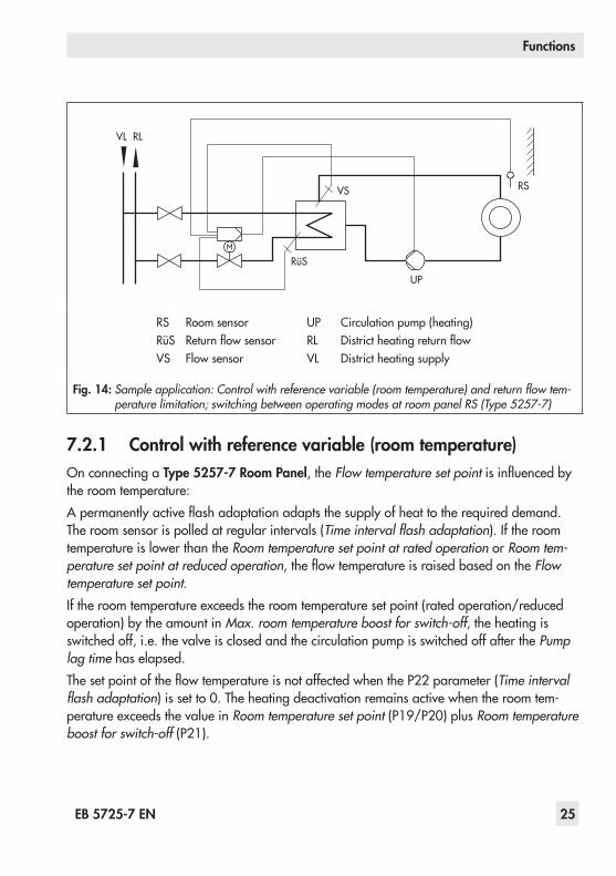
7.2.1 Control with reference variable (room temperature)On connecting a Type 5257-7 Room Panel, the Flow temperature set pointisinfluencedbythe room temperature:Apermanentlyactiveflashadaptation adapts the supply of heat to the required demand. The room sensor is polled at regular intervals (Time interval flash adaptation). If the room temperature is lower than the Room temperature set point at rated operation or Room tem-perature set point at reduced operation,theflowtemperatureisraisedbasedontheFlow temperature set point.If the room temperature exceeds the room temperature set point (rated operation/reduced operation) by the amount in Max. room temperature boost for switch-off, the heating is switched off, i.e. the valve is closed and the circulation pump is switched off after the Pump lag time has elapsed.ThesetpointoftheflowtemperatureisnotaffectedwhentheP22parameter(Time interval flash adaptation) is set to 0. The heating deactivation remains active when the room tem-perature exceeds the value in Room temperature set point (P19/P20) plus Room temperature boost for switch-off (P21).
RüS
UP
VS
VL RL
RS
RS Room sensor UP Circulation pump (heating)RüS Returnflowsensor RL DistrictheatingreturnflowVS Flow sensor VL District heating supply
Fig. 14: Sample application: Control with reference variable (room temperature) and return flow tem-perature limitation; switching between operating modes at room panel RS (Type 5257-7)
26 EB 5725-7 EN
Functions
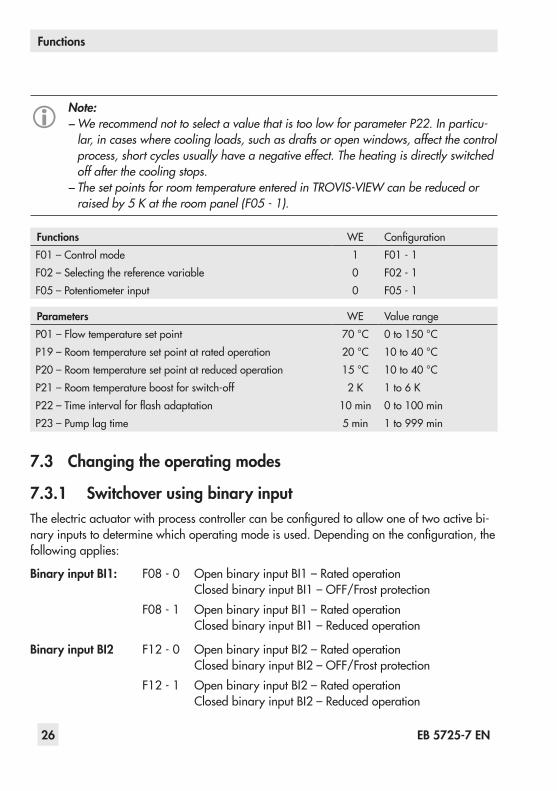
Note: − We recommend not to select a value that is too low for parameter P22. In particu-lar, in cases where cooling loads, such as drafts or open windows, affect the control process, short cycles usually have a negative effect. The heating is directly switched off after the cooling stops. − The set points for room temperature entered in TROVIS-VIEW can be reduced or raised by 5 K at the room panel (F05 - 1).
Functions WE ConfigurationF01 – Control mode 1 F01 - 1F02 – Selecting the reference variable 0 F02 - 1F05 – Potentiometer input 0 F05 - 1
Parameters WE Value rangeP01 – Flow temperature set point 70 °C 0to150 °CP19 – Room temperature set point at rated operation 20 °C 10to40 °CP20 – Room temperature set point at reduced operation 15 °C 10to40 °CP21 – Room temperature boost for switch-off 2 K 1to6 KP22–Timeintervalforflashadaptation 10 min 0to100 minP23 – Pump lag time 5 min 1to999 min
7.3 Changing the operating modes
7.3.1 Switchover using binary inputTheelectricactuatorwithprocesscontrollercanbeconfiguredtoallowoneoftwoactivebi-naryinputstodeterminewhichoperatingmodeisused.Dependingontheconfiguration,thefollowing applies:
Binary input BI1: F08 - 0 Open binary input BI1 – Rated operationClosed binary input BI1 – OFF/Frost protection
F08 - 1 Open binary input BI1 – Rated operationClosed binary input BI1 – Reduced operation
Binary input BI2 F12 - 0 Open binary input BI2 – Rated operationClosed binary input BI2 – OFF/Frost protection
F12 - 1 Open binary input BI2 – Rated operationClosed binary input BI2 – Reduced operation
EB 5725-7 EN 27
Functions
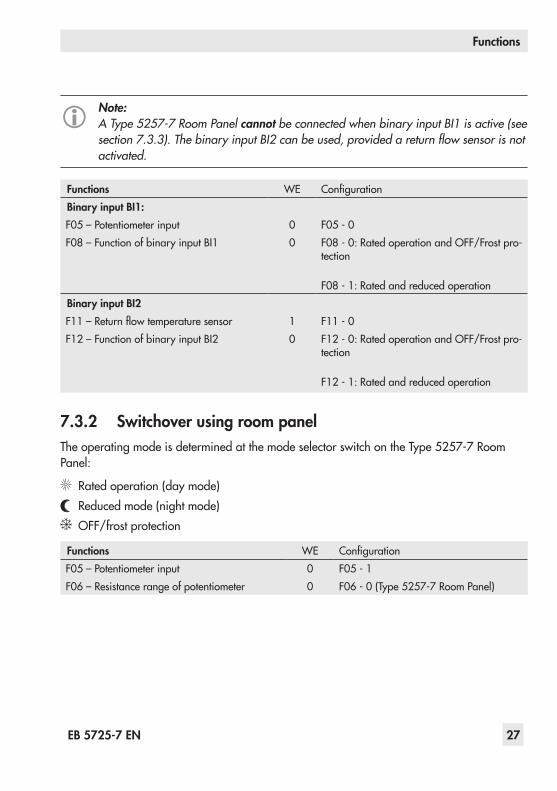
Note:A Type 5257-7 Room Panel cannot be connected when binary input BI1 is active (see section 7.3.3). The binary input BI2 can be used, provided a return flow sensor is not activated.
Functions WE ConfigurationBinary input BI1:F05 – Potentiometer input 0 F05 - 0F08 – Function of binary input BI1 0 F08 - 0: Rated operation and OFF/Frost pro-
tection
F08 - 1: Rated and reduced operationBinary input BI2 F11–Returnflowtemperaturesensor 1 F11 - 0F12 – Function of binary input BI2 0 F12 - 0: Rated operation and OFF/Frost pro-
tection
F12 - 1: Rated and reduced operation
7.3.2 Switchover using room panelTheoperatingmodeisdeterminedatthemodeselectorswitchontheType 5257-7RoomPanel:
Rated operation (day mode)Reduced mode (night mode)OFF/frost protection
Functions WE ConfigurationF05 – Potentiometer input 0 F05 - 1F06 – Resistance range of potentiometer 0 F06 - 0 (Type 5257-7 Room Panel)
28 EB 5725-7 EN
Functions
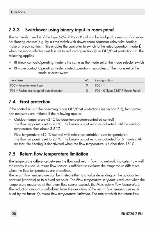
7.3.3 Switchover using binary input in room panelTheterminals1and4oftheType 5257-7RoomPanelcanbebridgedbymeansofanexter-nalfloatingcontact(e.g.byatimeswitchwithdownstreamcontactorrelaywithfloatingmake or break contact). This enables the controller to switch to the rated operation mode when the mode selector switch is set to reduced operation or OFF/Frost protection . The following applies:
− BI break contact Operating mode is the same as the mode set at the mode selector switch − BI make contact Operating mode is rated operation, regardless of the mode set at the
mode selector switch
Functions WE ConfigurationF05 – Potentiometer input 0 F05 - 1F06 – Resistance range of potentiometer 0 F06 - 0 (Type 5257-7 Room Panel)
7.4 Frost protectionIf the controller is in the operating mode OFF/Frost protection (see section 7.3), frost protec-tion measures are initiated if the following applies: − Outdoortemperature<3 °C(outdoor-temperature-controlledcontrol)Theflowsetpointissetto20 °C.Thebinaryoutputremainsactivateduntiltheoutdoortemperaturerisesabove3.5 °C.
− Flowtemperature<15 °C(controlwithreferencevariable(roomtemperature))Theflowsetpointissetto20 °C.Thebinaryoutputremainsactivatedfor5minutes.Af-terthat,theheatingisdeactivatedwhentheflowtemperatureishigherthan15° C.
7.5 Return flow temperature limitationThetemperaturedifferencebetweentheflowandreturnflowinanetworkindicateshowwelltheenergyisused.Areturnflowsensorissufficienttoevaluatethetemperaturedifferencewhentheflowtemperaturesarepredefined.Thereturnflowtemperaturecanbelimitedeithertoavaluedependingontheoutdoortem-perature(variable)ortoafixedsetpoint.TheFlow temperature set point is reduced when the temperaturemeasuredatthereturnflowsensorexceedstheMax. return flow temperature.Thereductionamountiscalculatedfromthedeviationofthereturnflowtemperaturemulti-plied by the factor Kp return flow temperature limitation.Therateatwhichthereturnflow
EB 5725-7 EN 29
Functions
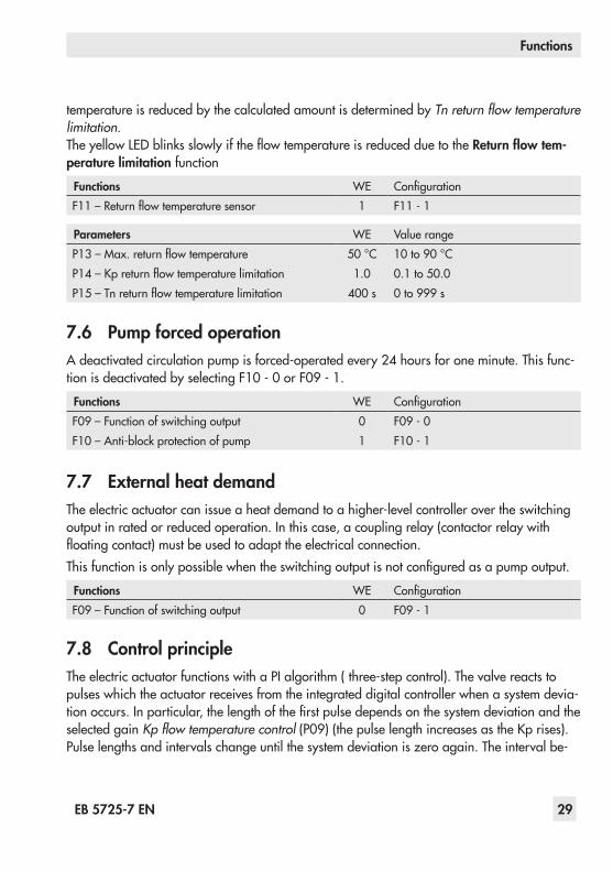
temperature is reduced by the calculated amount is determined by Tn return flow temperature limitation.TheyellowLEDblinksslowlyiftheflowtemperatureisreducedduetotheReturn flow tem-perature limitation function
Functions WE ConfigurationF11–Returnflowtemperaturesensor 1 F11 - 1
Parameters WE Value rangeP13–Max.returnflowtemperature 50 °C 10to90 °CP14–Kpreturnflowtemperaturelimitation 1.0 0.1 to 50.0P15–Tnreturnflowtemperaturelimitation 400 s 0 to 999 s
7.6 Pump forced operationA deactivated circulation pump is forced-operated every 24 hours for one minute. This func-tion is deactivated by selecting F10 - 0 or F09 - 1.
Functions WE ConfigurationF09 – Function of switching output 0 F09 - 0F10 – Anti-block protection of pump 1 F10 - 1
7.7 External heat demandThe electric actuator can issue a heat demand to a higher-level controller over the switching output in rated or reduced operation. In this case, a coupling relay (contactor relay with floatingcontact)mustbeusedtoadapttheelectricalconnection.Thisfunctionisonlypossiblewhentheswitchingoutputisnotconfiguredasapumpoutput.
Functions WE ConfigurationF09 – Function of switching output 0 F09 - 1
7.8 Control principleThe electric actuator functions with a PI algorithm ( three-step control). The valve reacts to pulses which the actuator receives from the integrated digital controller when a system devia-tionoccurs.Inparticular,thelengthofthefirstpulsedependsonthesystemdeviationandtheselected gain Kp flow temperature control(P09)(thepulselengthincreasesastheKprises).Pulse lengths and intervals change until the system deviation is zero again. The interval be-

30 EB 5725-7 EN
Functions
tweenindividualpulsesisinfluencedconsiderablybytheresettimeTn flow temperature con-trol (P10) (the interval time increases as the Tn rises). The valve transit time Ty actuator transit time for valve travel(P11)reflectsthetimethatthevalveneedstomovethroughtherangefrom0to100 %withoutstopping.Thedefaultsettingis35 s.
Travel Transit time6 mm 35 s12 mm 70 s15 mm 90 s
Note:The default setting is based on a travel of 6 mm. The transit time must be adjusted for the required travel range. Alternatively, it can be determined (see section 8.1.2).
The Dead band (P12) determines the reaction in steady state, i.e. the actuator is not active if the controlled variable moves within the dead band.
Parameters WE Value rangeP09–Kpflowtemperaturecontrol 2.0 0.1 to 50.0P10–Tnflowtemperaturecontrol 120 s 0 to 999 sP11 – Ty actuator transit time for valve travel 35 s 10 to 240 sP12 – Dead band (switching range) 2.0 % 0.5to5.0 %
7.9 Direction of actionIncreasing/increasing (F03 - 0) − Actual value < Set point: actuator stem retracts − Actual value < Set point: actuator stem extends
Increasing/decreasing (F03 - 1) − Actual value < Set point: actuator stem extends − Actual value > Set point: actuator stem retracts
Actuator stem extendsWith globe valves: Valve closedFor three-way mixing valves: PortA->ABopen,B->ABclosed(see Fig. 15)For three-way diverting valves: Port AB -> A closed, AB -> B open

EB 5725-7 EN 31
Functions
Actuator stem retractsWith globe valves: Valve openFor three-way mixing valves: PortA->ABclosed,B->ABopen(see Fig. 15)For three-way diverting valves: Port AB -> A open, AB -> B closed
Functions WE ConfigurationF03 – Direction of stem action 0 F03 - 0: Increasing/increasing >>
F03 - 1: Increasing/decreasing <>
7.10 Manual mode
7.10.1 HandwheelSeesection 5.1.
7.10.2 Command modeAmemorypencanbeconfiguredinTROVIS-VIEWtobeacommandpen.Thecommandpen allows the actuator stem to be moved to the open and closed positions.
0
A AB
B
Flow
Return flow
A
B
AB
AB A
B
Flow
Return flow
A AB
B
Flow
Return flow
AB A
B
Flow
Return flow
Mixing valve for:Mixing service Diverting service
Diverting valve for:Mixing service Diverting service
Fig. 15: Type 3226 Three-way Mixing Valve mounted onto TROVIS 5725-7 Electric Actuator with Process Controller
32 EB 5725-7 EN
Functions
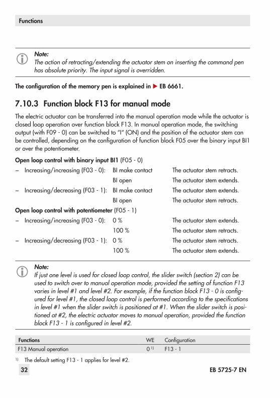
Note:The action of retracting/extending the actuator stem on inserting the command pen has absolute priority. The input signal is overridden.
The configuration of the memory pen is explained in u EB 6661.
7.10.3 Function block F13 for manual modeThe electric actuator can be transferred into the manual operation mode while the actuator is closed loop operation over function block F13. In manual operation mode, the switching output (with F09 - 0) can be switched to “I“ (ON) and the position of the actuator stem can becontrolled,dependingontheconfigurationoffunctionblockF05overthebinaryinputBI1or over the potentiometer.
Open loop control with binary input BI1 (F05 - 0) − Increasing/increasing (F03 - 0): BI make contact The actuator stem retracts.
BI open The actuator stem extends. − Increasing/decreasing (F03 - 1): BI make contact The actuator stem extends.
BI open The actuator stem retracts.Open loop control with potentiometer (F05 - 1) − Increasing/increasing (F03 - 0): 0 % The actuator stem extends.
100 % The actuator stem retracts. − Increasing/decreasing (F03 - 1): 0 % The actuator stem retracts.
100 % The actuator stem extends.
Note:If just one level is used for closed loop control, the slider switch (section 2) can be used to switch over to manual operation mode, provided the setting of function F13 varies in level #1 and level #2. For example, if the function block F13 - 0 is config-ured for level #1, the closed loop control is performed according to the specifications in level #1 when the slider switch is positioned at #1. When the slider switch is posi-tioned at #2, the electric actuator moves to manual operation, provided the function block F13 - 1 is configured in level #2.
Functions WE ConfigurationF13 Manual operation 0 1) F13 - 1
1) The default setting F13 - 1 applies for level #2.
EB 5725-7 EN 33
Functions
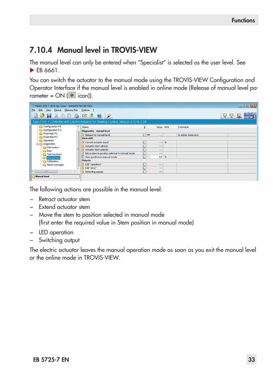
7.10.4 Manual level in TROVIS-VIEWThe manual level can only be entered when “Specialist” is selected as the user level. See u EB 6661.YoucanswitchtheactuatortothemanualmodeusingtheTROVIS-VIEWConfigurationandOperator Interface if the manual level is enabled in online mode (Release of manual level pa-rameter = ON ( icon)).
The following actions are possible in the manual level: − Retract actuator stem − Extend actuator stem − Move the stem to position selected in manual mode (firstentertherequiredvalueinStempositioninmanualmode)
− LED operation − Switching output
The electric actuator leaves the manual operation mode as soon as you exit the manual level or the online mode in TROVIS-VIEW.

34 EB 5725-7 EN
Device-specific readings and functions of the TROVIS-VIEW software
8 Device-specific readings and functions of the TROVIS-VIEW soft-ware
The TROVIS-VIEW software is explained in detail in the Operating Instructions u EB 6661.Select [?] menu in the software to access these instructions or download them from the SAMSON website (www. samson.de).Thissectiondescribesthedevice-specificreadingsandfunctionswhicharenotcoveredintheOperating Instructions u EB 6661.
8.1 Operating valuesOperationvalues(forexample,theflowtemperatureortheswitchingoutputstate)canberead in the Operation values folder in the TROVIS-VIEW software
Note: − The user level is set to “Customer” by default in TROVIS-VIEW. The current user lev-el is displayed on the status bar. When the user level is set to “Specialist”, addition-al data points are displayed in the Operation and Diagnostics folders as well as in the Test functions, Calibration and Status messages subfolders. − Change the user level to “Specialist” by selecting User Level in Device menu. See u EB 6661.
EB 5725-7 EN 35
Device-specific readings and functions of the TROVIS-VIEW software
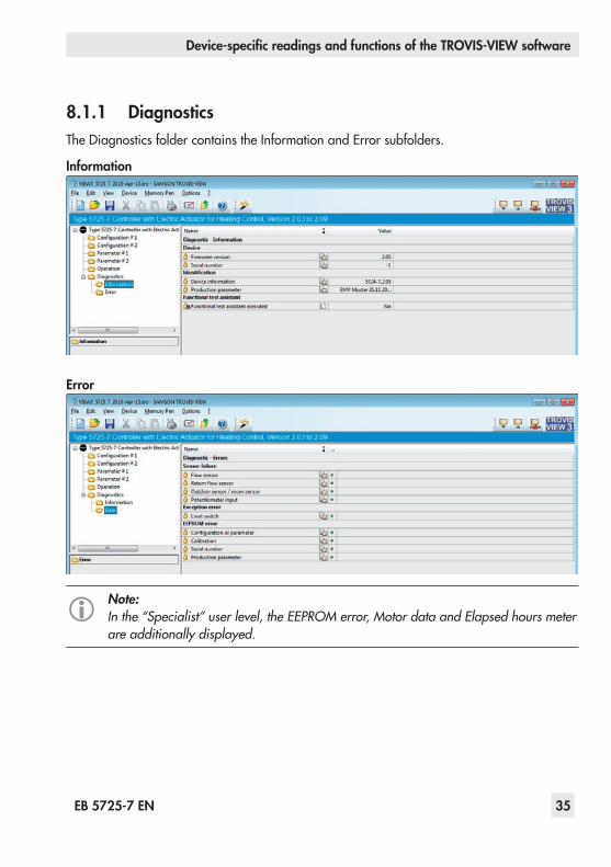
8.1.1 DiagnosticsThe Diagnostics folder contains the Information and Error subfolders.
Information
Error
Note:In the “Specialist” user level, the EEPROM error, Motor data and Elapsed hours meter are additionally displayed.
36 EB 5725-7 EN
Device-specific readings and functions of the TROVIS-VIEW software
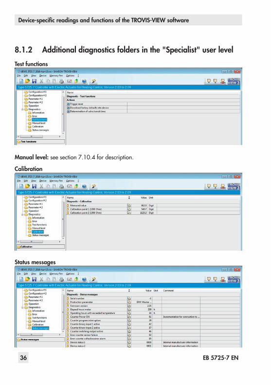
8.1.2 Additional diagnostics folders in the "Specialist" user levelTest functions
Manual level:seesection 7.10.4fordescription.
Calibration
Status messages

EB 5725-7 EN 37
Device-specific readings and functions of the TROVIS-VIEW software
8.2 SAMSON memory penThe SAMSON memory pen serves as a data carrier and is able to load and save data in its non-volatile memory.UsedinconjunctionwiththeTROVIS 5725-7ElectricActuatorwithProcessController,vari-ous functions of the memory pen are available: − Read data from the memory pen − Write data to the memory pen − Command mode (retract actuator stem, extend actuator stem, manual operation using
potentiometer or binary input) − Data logging to save the following data:
• Flow temperature• Returnflowtemperature• Binary input state• Switching output state• Position of the slider switch• Flow temperature set point• Set point reduction• Operating state• Cause for operating status• Remaining time for pump lag• Remaining time until anti-block protection of pump• Limit switch status• Current position of the actuator stem • Current correction value for closed loop control• P component from closed loop control• I component from closed loop control• Temperature inside device
The data are logged until the memory capacity of the memory pen is full.DatainthememorypencanbesavedasadataloggingfileusingtheTROVIS-VIEWsoft-ware.Theconfigurationofthememorypenisexplainedinu EB 6661.

38 EB 5725-7 EN
Device-specific readings and functions of the TROVIS-VIEW software
8.3 Functional test assistantTo establish communication, the serial interface of the computer must be connected to the se-rial interface port of the electric actuator using the SAMSON connecting cable.The functional test is performed with the help of an online wizard.
The following functions can be executed by selecting Functional test in Device menu or by clicking in the device toolbar: − The actuator stem extends. − The actuator stem retracts. − LEDs, pump or switching output can be checked − Measured data are shown.

EB 5725-7 EN 39
Configuration lists and customer data
9 Configuration lists and customer data
9.1 Function block list
Note:There are separate two configuration levels #1 and #2. Both configuration levels con-tain the functions F01 to F13 with the specified default settings and meanings.
The function blocks F01 to F13 have the following listed functions:F = Function block · WE = Default setting · 0 = OFF, 1 = ON
F Function WE Meaning
01 Control mode 1 0 – Fixed set point control →Section 7.21 – Control with reference variable → Section 7.1
02 Selecting the reference variable(only effective when F01 - 1)
0 0 – Outdoor sensor → Section 7.11 – Room sensor → Section 7.2.1
03 Direction of stem action 0 0 – Increasing/increasing >> → Section 7.91 – Increasing/decreasing <> → Section 7.9
04 Delayed outdoor temperature(only effective when F01 - 1 and F02 - 0)
0 0 – Without delay1 – With delay → Section 7.1.3
05 Potentiometer input 0 0 – Inactive, binary input 1 active → Section 7.3.11 – Active →Sections 7.1.1,7.3.2,and7.3.3
06 Resistance range of potentiometer(only effective when F05 - 1)
0 0–Type5257-7RoomPanel(1000-1100 ohm)→ Sections 7.3.2 and 7.3.3
1 – Remote adjuster (1000-2000 ohm) → Section 7.1.1
07 Function of potentiometer(only effective when F02 - 0 and F05 - 1)
0 0 – Heating characteristic level shift →Section 7.1.11 – Gradient shift →Section 7.1.1
08 Function of binary input BI1(only effective when F05 - 0)
0 0 – BI1 short-circuited: OFF with frost protection → Sec-tion 7.3.1
1 – BI1 short-circuited: Reduced operation →Section 7.3.1
09 Function of switching output 0 0 – BO as circulation pump control →Section 7.71 – BO as heat demand →Section 7.7

40 EB 5725-7 EN
Configuration lists and customer data
F Function WE Meaning
10 Anti-block protection of pumps(only effective when F09 - 0)
1 0 – No anti-block protection1–Whenpumpsaredeactivated:switchedonevery24 hfor
1 min.→Section 7.6
11 Returnflowtemperaturesensor
1 0 – Inactive, binary input 2 active →Section 7.3.11–Active,withreturnflowtemperaturelimitation→ Sec-
tion 7.5
12 Function of binary input BI2(only effective when F11 - 0)
0 0 – BI2 short-circuited: OFF with frost protection → Sec-tion 7.3.1
1 – BI2 short-circuited: Reduced operation →Section 7.3.1
13 Manual mode 0 1) 0 – Inactive, closed-loop operation1 – Manual mode (absolute priority)
1) The default setting F13 - 1 applies for level #2.
9.2 Parameter list
Note:There are separate two parameter levels #1 and #2. Both parameter levels contain the functions P01 to P23 with the specified default settings and setting ranges.
The parameters have the setting ranges as listed below.P = Parameter · WE = Default setting
P Parameters WE Adjustment range
01 Flow temperature set point 70 °C 0 to 150 °C
02 Flow temperature set-back in reduced opera-tion 15 K 0 to 50 K
03 Min.flowtemperature 20 °C 0 to 150 °C
04 Max.flowtemperature 120 °C 0 to 150 °C
05 Heating characteristic gradient 1.6 0.2 to 3.2
06 Heating characteristic level 0 K –30 to 30 K
07 Gradient shift range via potentiometer 1.0 0.0 to 1.5
08 Level shift range via potentiometer 15 K 0 to 30 K
09 Kpflowtemperaturecontrol 2.0 0.1 to 50.0

EB 5725-7 EN 41
Configuration lists and customer data
P Parameters WE Adjustment range
10 Tnflowtemperaturecontrol 120 s 0 to 999 s
11 Ty actuator transit time for valve travel 35 s 10 to 240 s
12 Dead band (switching range) 2.0 % 0.5 to 5.0 %
13 Max.returnflowtemperature 50 °C 10 to 90 s
14 Kpreturnflowtemperaturelimitation 1.0 0.1 to 50.0
15 Tnreturnflowtemperaturelimitation 400 s 0 to 999 s
16 Delay time for outdoor temperature 3.0 °C/h 1.0 to 6.0 °C/h
17 Outdoor temperature limit value at rated operation 22 °C 0 to 50 °C
18 Outdoor temperature limit value at reduced operation 15 °C 0 to 50 °C
19 Room temperature set point at rated operation 20 °C 10 to 40 °C
20 Room temperature set point at reduced operation 15 °C 10 to 40 °C
21 Max. room temperature boost for switch-off 2 K 1 to 6 K
22 Timeintervalforflashadaptation 10 min 0 to 100 min
23 Pump lag time 5 min 1 to 999 min

42 EB 5725-7 EN
Configuration lists and customer data
9.3 Customer settingFunction blocks Parameters
Performed setting Performed setting
F WE #1 #2 P WE #1 #2 Adjustment range
01 1 01 70 °C 0 to 150 °C
02 0 02 15 K 0 to 50 K
03 0 03 20 °C 0 to 150 °C
04 0 04 120 °C 0 to 150 °C
05 0 05 1.6 0.2 to 3.2
06 0 06 0 K –30 to 30 K
07 0 07 1.0 0.0 to 1.5
08 0 08 15 K 0 to 30 K
09 0 09 2.0 0.1 to 50.0
10 1 10 120 s 0 to 999 s
11 1 11 35 s 10 to 240 s
12 0 12 2.0 % 0.5 to 5.0 %
13 0 1) 13 50 °C 10 to 90 °C1) The default setting F13 -
1 applies for level #2.14 1.0 0.1 to 50.0
15 400 s 0 to 999 s
16 3.0 °C/h 1.0 to 6.0 °C/h
17 22 °C 0 to 50 °C
18 15 °C 0 to 50 °C
19 20 °C 10 to 40 °C
20 15 °C 10 to 40 °C
21 2 K 1 to 6 K
22 10 min 0 to 100 min
23 5 min 1 to 999 min
EB 5725-7 EN 43
Nameplate
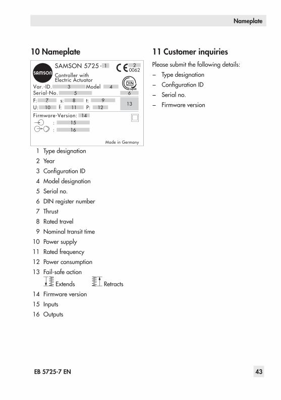
10 NameplateSAMSON 5725 - 1
Controller withElectric Actuator
Var.-ID. Model3 4Serial-No. 5F: 6 s: t:7 8 9U: f: P: 12
Firmware-Version:15:16:
Made in Germany
14
11
6
1310
00622
1 Type designation2 Year3 ConfigurationID4 Model designation5 Serial no.6 DIN register number7 Thrust8 Rated travel9 Nominal transit time
10 Power supply11 Rated frequency12 Power consumption13 Fail-safe action
Extends Retracts14 Firmware version15 Inputs16 Outputs
11 Customer inquiriesPlease submit the following details: − Type designation − ConfigurationID − Serial no. − Firmware version
44 EB 5725-7 EN
Appendix
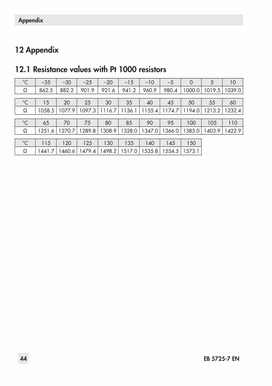
12 Appendix
12.1 Resistance values with Pt 1000 resistors°C –35 –30 –25 –20 –15 –10 –5 0 5 10Ω 862.5 882.2 901.9 921.6 941.2 960.9 980.4 1000.0 1019.5 1039.0
°C 15 20 25 30 35 40 45 50 55 60Ω 1058.5 1077.9 1097.3 1116.7 1136.1 1155.4 1174.7 1194.0 1213.2 1232.4
°C 65 70 75 80 85 90 95 100 105 110Ω 1251.6 1270.7 1289.8 1308.9 1328.0 1347.0 1366.0 1385.0 1403.9 1422.9
°C 115 120 125 130 135 140 145 150Ω 1441.7 1460.6 1479.4 1498.2 1517.0 1535.8 1554.5 1573.1

Index
46 EB 5725-7 EN
IndexAAccessories
Communication ................................ 8Heating applications ............................... 8Actuator stem ..................... 12, 13, 30, 31Anti-block protection ............................ 29Attachment
Force-locking .................................. 12Form-fit .......................................... 13
BBlinking pattern
Red LED ......................................... 10Yellow LED ..................................... 10
CCalibration .......................................... 36Command mode ............................ 31, 37Control
Fixed set point ................................ 24Outdoor temperature controlled ....... 21With reference variable (room tempera-ture) ............................................... 25
Control mode switchoverBinary input ................................... 26Binary input in room panel .............. 28Room panel .................................... 27
Control principle .................................. 29Coupling nut .................................. 12, 13Customer setting ................................... 42
DData logging ....................................... 37Delayed outdoor temperature adaptation 24Design ................................................... 6Diagnostics .......................................... 35Digital controller ..................................... 6Dimensions .......................................... 19Direction of action
Globe valve .............................. 30, 31Three-way diverting valve .......... 30, 31Three-way mixing valve ............. 30, 31
EElectrical connection ............................. 15Error ................................................... 35External demand .................................. 29External heat demand ........................... 29FFixed set point control ........................... 24Flash adaptation .................................. 25Forced pump operation ......................... 29Frost protection .................................... 28Functional test assistant ......................... 38Function block list ................................. 39HHandwheel .......................................... 18Hardware package ................................ 8Heating characteristic ........................... 21
Gradient ........................................ 21Level .............................................. 21
Index
EB 5725-7 EN 47
IInformation .......................................... 35MManual level ........................................ 33Manual mode ...................................... 31Memory pen .................................... 8, 37Mounting position ................................ 14NNameplate .......................................... 43OOperating values ................................. 34Outdoor-temperature-controlled control .. 21
Outdoor temperature adaptation ...... 24Override using potentiometer ........... 23Summer mode ................................ 23
PParameter list ....................................... 40Potentiometer ....................................... 23Potentiometer input ............................... 15Principle of operation ............................. 6RResistance values .................................. 44Returnflowtemperaturelimitation .......... 28Rod-type yoke ...................................... 13SSensor failure ....................................... 15Serial interface ....................................... 6Slider switch .......................................... 7Status messages ................................... 36Summer mode ...................................... 23
TTechnical data ........................................ 9Test ..................................................... 36Three-step control ................................. 29Travel indicator .............................. 14, 18TROVIS-VIEW ................................ 33, 34Type 5227-2 Outdoor Sensor ................ 15
Dimensions ..................................... 20Electrical connection .................. 16, 17
Type 5257-7 Room Panel ...................... 15Dimensions ..................................... 20Electrical connection ........................ 17Permissible temperatures/degree of protection ..................................... 8
Type 5267-2 Contact Sensor ................. 15Dimensions ..................................... 20Electrical connection .................. 16, 17Permissible temperatures/degree of protection ..................................... 8
Typetesting ............................................. 7WWire break .......................................... 15Wiring plans.................................. 16, 17

SAMSON AG · MESS- UND REGELTECHNIKWeismüllerstraße 3 · 60314 Frankfurt am Main, GermanyPhone: +49 69 4009-0 · Fax: +49 69 [email protected] · www.samson.de EB 5725-7 EN 20
18-0
5-17
· En
glish