Troubleshooting VLAN Trunk Protocol (VTP) · PDF file♦ The SAID for VLAN 8 is 100008....
22
Troubleshooting VLAN Trunk Protocol (VTP) Document ID: 98155 Contents Introduction Prerequisites Requirements Components Used Conventions Understand VTP Configure VTP VTP Troubleshooting and Caveats Unable to See VLAN Details in the show run Command Output Catalyst Switches Do Not Exchange VTP Information Catalyst Switch Automatically Changes VTP Mode from Client to Transparent Data Traffic Blocked between VTP Domains CatOS Switch Changes to VTP Transparent Mode, VTP-4-UNSUPPORTEDCFGRCVD: How a Recently Inserted Switch Can Cause Network Problems Recently Added Switch Does Not Get the VLANs From the VTP Server Reset the Configuration Revision Number All Ports Inactive After Power Cycle Trunk Down, which Causes VTP Problems VTP and STP (Logical Spanning Tree Port) The Case of VLAN 1 Troubleshoot VTP Configuration Revision Number Errors That Are Seen in the show vtp statistics Command Output Troubleshoot VTP Configuration Digest Errors That Are Seen in the show vtp statistics Command Output Unable to Change the VTP Mode of a Switch from Server / Transparent OSPF Hellos Blocked in a VTP Domain SW_VLAN-4-VTP_USER_NOTIFICATION Single Switchport Trunk That Allowed the vlan command Appears as Multiple Commands in the show running-config command Output Internal VLAN Usage Related Information Introduction This document provides information on how to troubleshoot VLAN Trunk Protocol (VTP). Prerequisites Requirements There are no specific requirements for this document. Components Used This document is not restricted to specific software and hardware versions.
Transcript of Troubleshooting VLAN Trunk Protocol (VTP) · PDF file♦ The SAID for VLAN 8 is 100008....
Troubleshooting VLAN Trunk Protocol (VTP)
Document ID: 98155
Contents
Introduction Prerequisites Requirements Components Used Conventions Understand VTP Configure VTP VTP Troubleshooting and Caveats Unable to See VLAN Details in the show run Command Output Catalyst Switches Do Not Exchange VTP Information Catalyst Switch Automatically Changes VTP Mode from Client to Transparent Data Traffic Blocked between VTP Domains CatOS Switch Changes to VTP Transparent Mode, VTP−4−UNSUPPORTEDCFGRCVD: How a Recently Inserted Switch Can Cause Network Problems Recently Added Switch Does Not Get the VLANs From the VTP Server Reset the Configuration Revision Number All Ports Inactive After Power Cycle Trunk Down, which Causes VTP Problems
VTP and STP (Logical Spanning Tree Port) The Case of VLAN 1 Troubleshoot VTP Configuration Revision Number Errors That Are Seen in the show vtp statisticsCommand Output Troubleshoot VTP Configuration Digest Errors That Are Seen in the show vtp statistics Command Output Unable to Change the VTP Mode of a Switch from Server / Transparent OSPF Hellos Blocked in a VTP Domain SW_VLAN−4−VTP_USER_NOTIFICATION Single Switchport Trunk That Allowed the vlan command Appears as Multiple Commands in the showrunning−config command Output Internal VLAN Usage Related Information
Introduction
This document provides information on how to troubleshoot VLAN Trunk Protocol (VTP).
Prerequisites
Requirements
There are no specific requirements for this document.
Components Used
This document is not restricted to specific software and hardware versions.

Conventions
Refer to Cisco Technical Tips Conventions for more information on document conventions.
Understand VTP
Refer to Understanding VLAN Trunk Protocol (VTP) for more information on VTP.
Configure VTP
Refer to Configuring VLAN Trunk Protocol (VTP) for information to configure VTP.
VTP Troubleshooting and Caveats
This section discusses some common troubleshooting situations for VTP.
Unable to See VLAN Details in the show run Command Output
Configuration changes in CatOS are written to NVRAM immediately after a change is made. In contrast,Cisco IOS® Software does not save configuration changes to NVRAM unless you issue the copyrunning−config startup−config command. VTP client and server systems require VTP updates from otherVTP servers to be immediately saved in NVRAM without user intervention. The VTP update requirementsare met by the default CatOS operation, but the Cisco IOS update model requires an alternative updateoperation.
For this alteration, a VLAN database was introduced into Cisco IOS Software as a method to immediatelysave VTP updates for VTP clients and servers. In some versions of software, this VLAN database is in theform of a separate file in NVRAM, called the vlan.dat file. You can view VTP/VLAN information that isstored in the vlan.dat file for the VTP client or VTP server if you issue the show vtp status command.
VTP server/client mode switches do not save the entire VTP/VLAN configuration to the startup config file inthe NVRAM when you issue the copy running−config startup−config command on these systems. It savesthe configuration in the vlan.dat file. This does not apply to systems that run as VTP transparent. VTPtransparent systems save the entire VTP/VLAN configuration to the startup config file in NVRAM when youissue the copy running−config startup−config command. For example, if you delete vlan.dat file after theconfiguration of the VTP in server or client mode and reload the switch, it resets the VTP configuration todefault settings. However, if you configure VTP in transparent mode, delete the vlan.dat and reload theswitch. This retains the VTP configuration.
This is an example of a default VTP configuration:
Switch#show vtp statusVTP Version : 2Configuration Revision : 0Maximum VLANs supported locally : 1005Number of existing VLANs : 5VTP Operating Mode : ClientVTP Domain Name : CISCOVTP Pruning Mode : DisabledVTP V2 Mode : DisabledVTP Traps Generation : DisabledMD5 digest : 0xD3 0x78 0x41 0xC8 0x35 0x56 0x89 0x97Configuration last modified by 0.0.0.0 at 0−0−00 00:00:00

You can configure normal−range VLANs (2 through 1000) when the switch is in either VTP server ortransparent mode. However, you can only configure extended−range VLANs (1025 through 4094) in VTPtransparent switches.
In order to display all the VLAN configurations, the VLAN ID, name, and so forth, that are stored inthe binary file, you must issue the show vlan command.
•
You can display the VTP information, the mode, domain, and so forth, with use of the show vtpstatus command.
•
The VLAN information and the VTP information are not displayed in the show running−configcommand output when the switch is in the VTP server/client mode. This is normal behavior of theswitch.
Router#show run | include vlanvlan internal allocation policy ascending
Router#show run | include vtp
•
Switches that are in VTP transparent mode display the VLAN and VTP configurations in the showrunning−config command output because this information is also stored in the configuration text file.
Router#show run | include vlanvlan internal allocation policy ascendingvlan 1 tb−vlan1 1002 tb−vlan2 1003vlan 20−21,50−51 vlan 1002 tb−vlan1 1 tb−vlan2 1003vlan 1003 tb−vlan1 1 tb−vlan2 1002vlan 1004vlan 1005 Router#show run | include vtpvtp domain ciscovtp mode transparent
•
Note: Extended−range VLANs are not supported by 3500XL. The 2900XL and 3500XL can use onlyVLANs in the range of 1 to 1001, and they do not support extended−range VLANs. If you upgrade thesoftware of the switch, it does not bring an enhancement to support the configuration of extended−rangeVLANs.
Catalyst Switches Do Not Exchange VTP Information
VTP allows switches to advertise VLAN information between other members of the same VTP domain. VTPallows a consistent view of the switched network across all switches. There are several reasons why theVLAN information can fail to be exchanged.
Verify these items if switches that run VTP fail to exchange VLAN information:
VTP information only passes through a trunk port. Make sure that all ports that interconnect switchesare configured as trunks and are actually trunking.
Make sure that if EtherChannels are created between two switches, only Layer 2 EtherChannelspropagate VLAN information.
•
Make sure that the VLANs are active in all the devices.• One of the switches must be the VTP server in a VTP domain. All VLAN changes must be done on•

this switch in order to have them propagated to the VTP clients.The VTP domain name must match and it is case sensitive. CISCO and cisco are two different domainnames.
•
Make sure that no password is set between the server and client. If any password is set, make sure thatthe password is the same on both sides.
•
Every switch in the VTP domain must use the same VTP version. VTP V1 and VTP V2 are notcompatible on switches in the same VTP domain. Do not enable VTP V2 unless every switch in theVTP domain supports V2.
Note: VTP V2 is disabled by default on VTP V2−capable switches. When you enable VTP V2 on aswitch, every VTP V2−capable switch in the VTP domain enables V2. You can only configure theversion on switches in VTP server or transparent mode.
•
Switches that operate in transparent mode drop VTP advertisements if they are not in the same VTPdomain.
•
The extended−range VLANs are not propagated. Therefore, you must configure extended−rangeVLANs manually on each network device.
Note: In the future, the Catalyst 6500 Cisco IOS Software switches support VTP Version 3. Thisversion is able to transmit extended−range VLANs. So far, VTP Version 3 is only supported onCatOS. Refer to the Understanding How VTP Version 3 Works section of Configuring VTP for moreinformation on VTP Version 3.
•
The Security Association Identifier (SAID) values must be unique. SAID is a user−configurable,4−byte VLAN identifier. The SAID identifies traffic that belongs to a particular VLAN. The SAIDalso determines to which VLAN each packet is switched. The SAID value is 100,000 plus the VLANnumber. These are two examples:
The SAID for VLAN 8 is 100008.♦ The SAID for VLAN 4050 is 104050.♦
•
The updates from a VTP server do not get updated on a client if the client already has a higher VTPrevision number. Also, the client does not allow these updates to flow to its downstream VTP clientsif the client has a higher revision number than that which the VTP server sends.
•
Catalyst Switch Automatically Changes VTP Mode from Client toTransparent
Some Catalyst Layer 2 and Layer 3 fixed configuration switches change the VTP mode automatically fromclient to transparent with this error message:
%SW_VLAN−6−VTP_MODE_CHANGE: VLAN manager changing device mode from CLIENT to TRANSPARENT.
Either of these two reasons can cause the automatic VTP mode change in these switches:
More VLANs run on the Spanning Tree Protocol (STP) than the switch can support.
Catalyst Layer 2 and Layer 3 fixed configuration switches support a different maximum number ofinstances of STP with the use of per−VLAN spanning tree+ (PVST+). For example, the Catalyst 2940supports four instances of STP in PVST+ mode, while the Catalyst 3750 supports 128 instances ofSTP in PVST+ mode. If more than the maximum number of VLANs is defined in the VTP, theVLANs that remain operate with STP disabled.
If the number of instances of STP that is already in use is greater than the maximum number, you candisable STP on one of the VLANs and enable it on the VLAN where you want STP to run. Issue theno spanning−tree vlan vlan−id global configuration command in order to disable STP on a specific
•

VLAN. Then, issue the spanning−tree vlan vlan−id global configuration command in order toenable STP on the desired VLAN.
Note: Switches that do not run STP still forward the bridge protocol data units (BPDUs) that theyreceive. In this way, the other switches on the VLAN that have a running STP instance can breakloops. Therefore, STP must run on enough switches in order to break all the loops in the network. Forexample, at least one switch on each loop in the VLAN must run STP. You do not need to run STP onall switches in the VLAN. However, if you run STP only on a minimal set of switches, a change tothe network can introduce a loop into the network and can result in a broadcast storm.
Workarounds:
Reduce the number of VLANs that are configured to a number that the switch supports.♦ Configure the IEEE 802.1s Multiple STP (MSTP) on the switch in order to map multipleVLANs to a single STP instance.
♦
Use switches and/or images (Enhanced Image [EI]) which support a greater number ofVLANs.
♦
The switch receives more VLANs from a connected switch than the switch can support.
An automatic VTP mode change also can occur if the switch receives a VLAN configuration databasemessage that contains more than a set number of VLANs. This normally happens in Catalyst Layer 2and Layer 3 fixed configuration switches when they are connected to a VTP domain that has moreVLANs than are supported locally.
Workarounds:
Configure the allowed VLAN list on the trunk port of the connected switch in order to restrictthe number of VLANs that are passed to the client switch.
♦
Enable pruning on the VTP server switch.♦ Use switches and/or images (EI) which support a greater number of VLANs.♦
•
Data Traffic Blocked between VTP Domains
Sometimes it is required to connect to switches that belong to two different VTP domains. For example, thereare two switches called Switch1 and Switch2. Switch1 belongs to VTP domain cisco1 and Switch2 belongs toVTP domain cisco2. When you configure trunk between these two switches with the Dynamic TrunkNegotiation (DTP), the trunk negotiation fails and the trunk between the switches does not form, because theDTP sends the VTP domain name in a DTP packet. Because of this, the data traffic does not pass between theswitches.
Switch1#show vtp statusVTP Version : 2Configuration Revision : 0Maximum VLANs supported locally : 1005Number of existing VLANs : 9VTP Operating Mode : ServerVTP Domain Name : cisco1VTP Pruning Mode : DisabledVTP V2 Mode : DisabledVTP Traps Generation : Disabled
Switch2#show vtp statusVTP Version : 2Configuration Revision : 2Maximum VLANs supported locally : 1005Number of existing VLANs : 42VTP Operating Mode : Server
VTP Domain Name : cisco2VTP Pruning Mode : DisabledVTP V2 Mode : DisabledVTP Traps Generation : Disabled
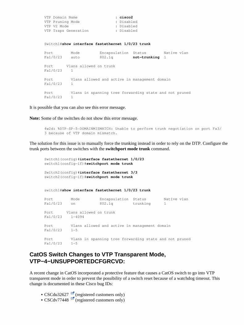
Switch1#show interface fastethernet 1/0/23 trunk
Port Mode Encapsulation Status Native vlanFa1/0/23 auto 802.1q not−trunking 1
Port Vlans allowed on trunkFa1/0/23 1
Port Vlans allowed and active in management domainFa1/0/23 1
Port Vlans in spanning tree forwarding state and not prunedFa1/0/23 1
It is possible that you can also see this error message.
Note: Some of the switches do not show this error message.
4w2d: %DTP−SP−5−DOMAINMISMATCH: Unable to perform trunk negotiation on port Fa3/3 because of VTP domain mismatch.
The solution for this issue is to manually force the trunking instead in order to rely on the DTP. Configure thetrunk ports between the switches with the switchport mode trunk command.
Switch1(config)#interface fastethernet 1/0/23switch1(config−if)#switchport mode trunk
Switch2(config)#interface fastethernet 3/3switch2(config−if)#switchport mode trunk
switch1#show interface fastethernet 1/0/23 trunk
Port Mode Encapsulation Status Native vlanFa1/0/23 on 802.1q trunking 1
Port Vlans allowed on trunkFa1/0/23 1−4094
Port Vlans allowed and active in management domainFa1/0/23 1−5
Port Vlans in spanning tree forwarding state and not prunedFa1/0/23 1−5
CatOS Switch Changes to VTP Transparent Mode,VTP−4−UNSUPPORTEDCFGRCVD:
A recent change in CatOS incorporated a protective feature that causes a CatOS switch to go into VTPtransparent mode in order to prevent the possibility of a switch reset because of a watchdog timeout. Thischange is documented in these Cisco bug IDs:
CSCdu32627 (registered customers only)• CSCdv77448 (registered customers only)•

How Do I Determine If My Switch Might Be Affected?
The watchdog timeout can occur if these two conditions are met:
The Token Ring VLAN (1003) is translated to VLAN 1.• You make a change in VLAN 1.•
Issue the show vlan command on the Catalyst in order to observe the Token Ring VLAN translation. This isan example of show vlan command output:
VLAN Type SAID MTU Parent RingNo BrdgNo Stp BrdgMode Trans1 Trans2−−−− −−−−− −−−−−−−−−− −−−−− −−−−−− −−−−−− −−−−−− −−−− −−−−−−−− −−−−−− −−−−−−1 enet 100001 1500 − − − − − 1003
How Does CatOS Version 6.3(3) Protect My Switch from a Watchdog Timeout?
There is a protective feature in order to prevent a watchdog timeout in this CatOS version. The Catalystswitch switches from VTP server or client to VTP transparent mode.
How Do I Determine If My Switch Has Gone to VTP Transparent Mode in Order to ProtectAgainst a Watchdog Timeout?
Your switch has gone to VTP transparent mode if the logging level for the VTP is raised to 4.
Console> (enable) set logging level vtp 4 default
You see this message when the switchover occurs:
VTP−4−UNSUPPORTEDCFGRCVD:Rcvd VTP advert with unsupported vlan config on trunk mod/port− VTP mode changed to transparent
What Are the Negative Effects When the Switch Goes to VTP Transparent Mode?
If pruning is enabled, the trunks go down.• If the trunks go down and no other ports are in that VLAN, the VLAN interface in the installedMultilayer Switch Feature Card (MSFC) goes down.
•
If these effects occur, and this switch is in the core of your network, your network can be negatively affected.
Where Does the Unsupported VTP Configuration Come From?
Any Cisco IOS Software−based switch, such as the switches in this list, can supply the unsupported VTPconfiguration:
A Catalyst 2900/3500XL• A Cisco IOS Software Catalyst 6500• A Cisco IOS Software−based Catalyst 4000•
These products translate the 1003 VLAN to VLAN 1 by default.
What Is the Solution?
The solution in CatOS−based switches enables the switches to handle this translated information properly.The solution for the Cisco IOS Software−based switches is to remove this default translation and match thebehavior of the CatOS−based switches. These are the integrated fixed versions that are currently available:

Catalyst SwitchFixed Releases
CatOS switches 5.5(14) and later 6.3(6) andlater 7.2(2) and later
Catalyst 4000 (SupervisorEngine III)
Not affectedCatalyst 6500 (SupervisorEngine Cisco IOS Software) Cisco IOS Software Release
12.1(8a)EX and laterCatalyst 2900 and 3500XL Cisco IOS Software Release
12.0(5)WC3 and later
If you cannot upgrade to images that have these fixes integrated, you can modify the configuration in theCisco IOS Software−based switches. Use this procedure if the switch is a VTP server:
goss#vlan data
goss(vlan)#no vlan 1 tb−vlan1 tb−vlan2
Resetting translation bridge VLAN 1 to defaultResetting translation bridge VLAN 2 to default
goss(vlan)#no vlan 1003 tb−vlan1 tb−vlan2
Resetting translation bridge VLAN 1 to defaultResetting translation bridge VLAN 2 to default
goss(vlan)#apply
APPLY completed.
goss(vlan)#exit
APPLY completed.Exiting....
The 1002 VLAN can be translated, but you can also remove it if you include this in your configuration:
goss(vlan)#no vlan 1002 tb−vlan1 tb−vlan2
Resetting translation bridge VLAN 1 to defaultResetting translation bridge VLAN 2 to default
When Exactly Does My Switch Change to VTP Transparent Mode?
Some confusion exists about when this switchover to VTP transparent mode occurs. The scenarios in thissection provide examples of when the switchover can happen.
Example 1
These are the initial conditions:
•

Both the Catalyst 6500 and the Catalyst 3500XL are VTP servers with the same VTPconfiguration revision number.
♦
Both servers have the same VTP domain name and the same VTP password, if the passwordis configured.
♦
The Catalyst 3500XL has the translated Token Ring VLAN.♦ You start the servers while they are disconnected.♦
If you connect these two switches, the Catalyst 6500 goes to VTP transparent mode. Of course, thisalso happens if the Cisco 3500XL has a higher VTP configuration revision number than the Catalyst6500 configuration revision number. Moreover, if the switch to VTP transparent mode occurs whenyou physically connect the two switches, you can reasonably assume that the change would also occurif you booted the Catalyst 6500 for the first time while the switch was already connected.Example 2
These are the initial conditions:
The Catalyst 6500 is a VTP server.♦ The Catalyst 3500XL is a VTP client.♦ The Catalyst 3500XL has a higher VTP configuration revision number than the Catalyst 6500configuration revision number.
♦
Both switches have the same VTP domain and the same VTP password, if the password isconfigured.
♦
The Catalyst 3500XL has the translated Token Ring VLAN.♦ You start the servers while they are disconnected.♦
If you connect these two switches, the Catalyst 6500 goes to VTP transparent mode. In this scenario,if the Catalyst 3500XL has a lower configuration revision number than the Catalyst 6500configuration revision number, the Catalyst 6500 does not switch to VTP transparent mode. If theCatalyst 3500XL has the same configuration revision number, the Catalyst 6500 does not go to VTPtransparent mode. However, the translation is still present in the Catalyst 3500XL.
•
What Is the Quickest Way to Recover After I Notice the Translation in My Network?
Even if you correct the Token Ring VLAN information in one switch, such as the switch that malfunctioned,the information can propagate throughout your network. You can use the show vlan command in order todetermine if this occurred. Therefore, the quickest way to recover is to perform these steps:
Take a Cisco IOS Software−based switch, such as a Catalyst XL that is connected to the network, andchange the switch to a VTP server.
1.
Remove the translated VLANs.2. After you apply the change in the switch, reconnect the switch to the network.
The change should be propagated to all the other VTP servers and clients.
You can use the show vlan command in order to verify that the translation is gone in the network. Atthis point, you should be able to change the affected CatOS 6.3(3) switch back to a VTP server.
Note: The Catalyst XL switches do not support as many VLANs as the Catalyst 6500s support.Ensure that all the VLANs in the Catalyst 6500 exist in the Catalyst XL switch before you reconnectthem. For example, you do not want to connect a Catalyst 3548XL with 254 VLANs and a higherVTP configuration revision number to a Catalyst 6500 that has 500 VLANs configured.
3.
How a Recently Inserted Switch Can Cause Network Problems
This problem occurs when you have a large switched domain that is all in the same VTP domain, and youwant to add one switch in the network.

This switch was previously used in the lab, and a good VTP domain name was entered. The switch wasconfigured as a VTP client and was connected to the rest of the network. Then, you brought the ISL link up tothe rest of the network. In just a few seconds, the whole network was down. How did this happen?
The configuration revision number of the switch that you inserted was higher than the configuration revisionnumber of the VTP domain. Therefore, your recently introduced switch, with almost no configured VLANs,erased all VLANs through the VTP domain.
This occurs whether the switch is a VTP client or a VTP server. A VTP client can erase VLAN informationon a VTP server. You can tell that this has occurred when many of the ports in your network go into inactivestate but continue to be assigned to a nonexistent VLAN.
Solution
Quickly reconfigure all of the VLANs on one of the VTP servers.
What to Remember
Always make sure that the configuration revision number of all switches that you insert into the VTP domainis lower than the configuration revision number of the switches that are already in the VTP domain.
If you have the output of a show tech−support command from your Cisco device, you can use the OutputInterpreter (registered customers only) in order to display potential issues and fixes.
Example
Complete these steps in order to see an example of this problem:
Issue these commands in order to see that clic has 7 VLANs (1, 2, 3, and the defaults), clic is the VTPserver in the domain named test, and port 2/3 is in VLAN 3:
clic (enable) show vlan
1993 May 25 05:09:50 %PAGP−5−PORTTOSTP:Port 2/1 joined bridge port 2/1 lanVLAN Name Status IfIndex Mod/Ports, Vlans−−−− −−−−−−−−−−−−−−−−−−−−−−−−−−−−−−−− −−−−−−−−− −−−−−−− −−−−−−−−−−−−−−−−−−−−−−−−1 default active 65 2/2,2/4−502 VLAN0002 active 703 VLAN0003 active 71 2/31002 fddi−default active 661003 token−ring−default active 691004 fddinet−default active 671005 trnet−default active 68 68
clic (enable) show vtp domain
Domain Name Domain Index VTP Version Local Mode Password−−−−−−−−−−−−−−−−−−−−−−−−−−−−−−−− −−−−−−−−−−−− −−−−−−−−−−− −−−−−−−−−−− −−−−−−−−−−test 1 2 server −
Vlan−count Max−vlan−storage Config Revision Notifications−−−−−−−−−− −−−−−−−−−−−−−−−− −−−−−−−−−−−−−−− −−−−−−−−−−−−−7 1023 0 disabled
Last Updater V2 Mode Pruning PruneEligible on Vlans−−−−−−−−−−−−−−− −−−−−−−− −−−−−−−− −−−−−−−−−−−−−−−−−−−−−−−−−0.0.0.0 disabled disabled 2−1000
clic (enable) show port 2/3
1.

Port Name Status Vlan Level Duplex Speed Type−−−−− −−−−−−−−−−−−−−−−−− −−−−−−−−−− −−−−−−−−−− −−−−−− −−−−−− −−−−− −−−−−−−−−−−− 2/3 connected 3 normal 10 half 10/100BaseTX
Connect bing, which is a lab switch on which VLANs 4, 5, and 6 were created.
Note: The configuration revision number is 3 in this switch.
bing (enable) show vlan
VLAN Name Status IfIndex Mod/Ports, Vlans−−−− −−−−−−−−−−−−−−−−−−−−−−−−−−−−−−−− −−−−−−−−− −−−−−−− −−−−−−−−−−−−−−−−−−−−−−−−1 default active 4 2/1−48 3/1−64 VLAN0004 active 635 VLAN0005 active 646 VLAN0006 active 651002 fddi−default active 51003 token−ring−default active 81004 fddinet−default active 61005 trnet−default active 7
2.
Place bing in the same VTP domain (test).
bing (enable) show vtp domain
Domain Name Domain Index VTP Version Local Mode Password−−−−−−−−−−−−−−−−−−−−−−−−−−−−−−−− −−−−−−−−−−−− −−−−−−−−−−− −−−−−−−−−−− −−−−−−−−−−test 1 2 server −
Vlan−count Max−vlan−storage Config Revision Notifications−−−−−−−−−− −−−−−−−−−−−−−−−− −−−−−−−−−−−−−−− −−−−−−−−−−−−−8 1023 3 disabled
Last Updater V2 Mode Pruning PruneEligible on Vlans−−−−−−−−−−−−−−− −−−−−−−− −−−−−−−− −−−−−−−−−−−−−−−−−−−−−−−−−10.200.8.38 disabled disabled 2−1000
3.
Configure the trunk between the two switches in order to integrate bing in the network.
Bing erased the clic VLAN, and now clic has VLANs 4, 5, and 6. However, clic no longer hasVLANs 2 and 3, and port 2/3 is inactive.
clic (enable) show vtp domain
Domain Name Domain Index VTP Version Local Mode Password−−−−−−−−−−−−−−−−−−−−−−−−−−−−−−−− −−−−−−−−−−−− −−−−−−−−−−− −−−−−−−−−−− −−−−−−−−−−test 1 2 server −
Vlan−count Max−vlan−storage Config Revision Notifications−−−−−−−−−− −−−−−−−−−−−−−−−− −−−−−−−−−−−−−−− −−−−−−−−−−−−−8 1023 3 disabled
Last Updater V2 Mode Pruning PruneEligible on Vlans−−−−−−−−−−−−−−− −−−−−−−− −−−−−−−− −−−−−−−−−−−−−−−−−−−−−−−−−10.200.8.38 disabled disabled 2−1000clic (enable)
clic (enable) show vlan
VLAN Name Status IfIndex Mod/Ports, Vlans−−−− −−−−−−−−−−−−−−−−−−−−−−−−−−−−−−−− −−−−−−−−− −−−−−−− −−−−−−−−−−−−−−−−−−−−−−−−1 default active 65 2/2,2/4−504 VLAN0004 active 725 VLAN0005 active 736 VLAN0006 active 74
4.
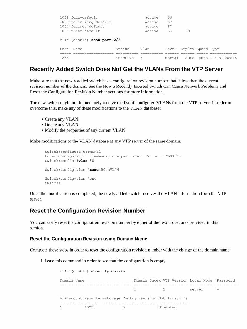
1002 fddi−default active 661003 token−ring−default active 691004 fddinet−default active 671005 trnet−default active 68 68
clic (enable) show port 2/3
Port Name Status Vlan Level Duplex Speed Type−−−−− −−−−−−−−−−−−−−−−−− −−−−−−−−−− −−−−−−−−−− −−−−−− −−−−−− −−−−− −−−−−−−−−−−− 2/3 inactive 3 normal auto auto 10/100BaseTX
Recently Added Switch Does Not Get the VLANs From the VTP Server
Make sure that the newly added switch has a configuration revision number that is less than the currentrevision number of the domain. See the How a Recently Inserted Switch Can Cause Network Problems andReset the Configuration Revision Number sections for more information.
The new switch might not immediately receive the list of configured VLANs from the VTP server. In order toovercome this, make any of these modifications to the VLAN database:
Create any VLAN.• Delete any VLAN.• Modify the properties of any current VLAN.•
Make modifications to the VLAN database at any VTP server of the same domain.
Switch#configure terminalEnter configuration commands, one per line. End with CNTL/Z.Switch(config)#vlan 50
Switch(config−vlan)#name 50thVLAN
Switch(config−vlan)#endSwitch#
Once the modification is completed, the newly added switch receives the VLAN information from the VTPserver.
Reset the Configuration Revision Number
You can easily reset the configuration revision number by either of the two procedures provided in thissection.
Reset the Configuration Revision using Domain Name
Complete these steps in order to reset the configuration revision number with the change of the domain name:
Issue this command in order to see that the configuration is empty:
clic (enable) show vtp domain
Domain Name Domain Index VTP Version Local Mode Password−−−−−−−−−−−−−−−−−−−−−−−−−−−−−−−− −−−−−−−−−−−− −−−−−−−−−−− −−−−−−−−−−− −−−−−−−−−− 1 2 server −
Vlan−count Max−vlan−storage Config Revision Notifications−−−−−−−−−− −−−−−−−−−−−−−−−− −−−−−−−−−−−−−−− −−−−−−−−−−−−−5 1023 0 disabled
1.

Last Updater V2 Mode Pruning PruneEligible on Vlans−−−−−−−−−−−−−−− −−−−−−−− −−−−−−−− −−−−−−−−−−−−−−−−−−−−−−−−−0.0.0.0 disabled disabled 2−1000clic (enable)
Configure the domain name, which is test in this example, and create two VLANs.
The configuration revision number goes up to 2:
clic (enable) set vtp domain test
VTP domain test modified
clic (enable) set vlan 2
Vlan 2 configuration successful
clic (enable) set vlan 3
Vlan 3 configuration successful
clic (enable) show vtp domain
Domain Name Domain Index VTP Version Local Mode Password−−−−−−−−−−−−−−−−−−−−−−−−−−−−−−−− −−−−−−−−−−−− −−−−−−−−−−− −−−−−−−−−−− −−−−−−−−−−test 1 2 server −
Vlan−count Max−vlan−storage Config Revision Notifications−−−−−−−−−− −−−−−−−−−−−−−−−− −−−−−−−−−−−−−−− −−−−−−−−−−−−−7 1023 2 disabled
Last Updater V2 Mode Pruning PruneEligible on Vlans−−−−−−−−−−−−−−− −−−−−−−− −−−−−−−− −−−−−−−−−−−−−−−−−−−−−−−−−0.0.0.0 disabled disabled 2−1000clic (enable)
2.
Change the domain name from test to cisco.
The configuration revision number is back to 0, and all the VLANs are still present:
clic (enable) set vtp domain cisco
VTP domain cisco modified
clic (enable) show vtp domain
Domain Name Domain Index VTP Version Local Mode Password−−−−−−−−−−−−−−−−−−−−−−−−−−−−−−−− −−−−−−−−−−−− −−−−−−−−−−− −−−−−−−−−−− −−−−−−−−−−cisco 1 2 server −
Vlan−count Max−vlan−storage Config Revision Notifications−−−−−−−−−− −−−−−−−−−−−−−−−− −−−−−−−−−−−−−−− −−−−−−−−−−−−−7 1023 0 disabled
Last Updater V2 Mode Pruning PruneEligible on Vlans−−−−−−−−−−−−−−− −−−−−−−− −−−−−−−− −−−−−−−−−−−−−−−−−−−−−−−−−0.0.0.0 disabled disabled 2−1000
3.
Change the VTP domain name from cisco back to test.
The configuration revision is 0. There is no risk that anything can be erased, and all the previouslyconfigured VLANs remain:
clic (enable) set vtp domain test
VTP domain test modified
4.
clic (enable) show vtp domain
Domain Name Domain Index VTP Version Local Mode Password−−−−−−−−−−−−−−−−−−−−−−−−−−−−−−−− −−−−−−−−−−−− −−−−−−−−−−− −−−−−−−−−−− −−−−−−−−−−test 1 2 server −
Vlan−count Max−vlan−storage Config Revision Notifications−−−−−−−−−− −−−−−−−−−−−−−−−− −−−−−−−−−−−−−−− −−−−−−−−−−−−−7 1023 0 disabled
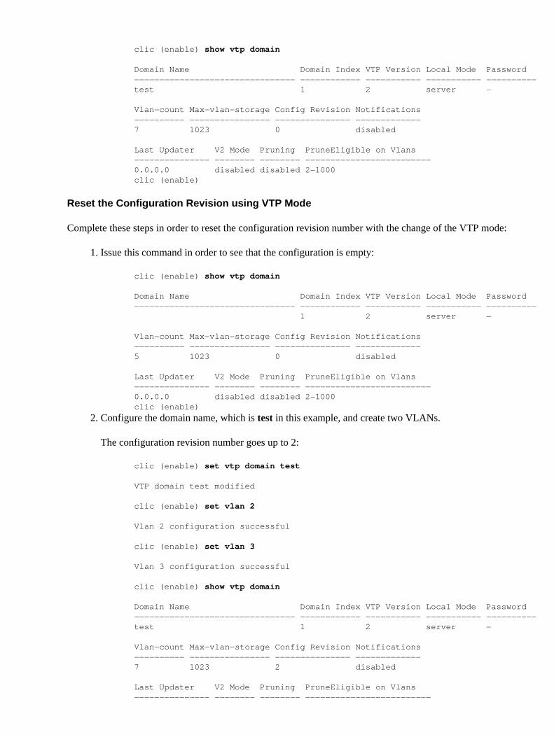
Last Updater V2 Mode Pruning PruneEligible on Vlans−−−−−−−−−−−−−−− −−−−−−−− −−−−−−−− −−−−−−−−−−−−−−−−−−−−−−−−−0.0.0.0 disabled disabled 2−1000clic (enable)
Reset the Configuration Revision using VTP Mode
Complete these steps in order to reset the configuration revision number with the change of the VTP mode:
Issue this command in order to see that the configuration is empty:
clic (enable) show vtp domain
Domain Name Domain Index VTP Version Local Mode Password−−−−−−−−−−−−−−−−−−−−−−−−−−−−−−−− −−−−−−−−−−−− −−−−−−−−−−− −−−−−−−−−−− −−−−−−−−−− 1 2 server −
Vlan−count Max−vlan−storage Config Revision Notifications−−−−−−−−−− −−−−−−−−−−−−−−−− −−−−−−−−−−−−−−− −−−−−−−−−−−−−5 1023 0 disabled
Last Updater V2 Mode Pruning PruneEligible on Vlans−−−−−−−−−−−−−−− −−−−−−−− −−−−−−−− −−−−−−−−−−−−−−−−−−−−−−−−−0.0.0.0 disabled disabled 2−1000clic (enable)
1.
Configure the domain name, which is test in this example, and create two VLANs.
The configuration revision number goes up to 2:
clic (enable) set vtp domain test
VTP domain test modified
clic (enable) set vlan 2
Vlan 2 configuration successful
clic (enable) set vlan 3
Vlan 3 configuration successful
clic (enable) show vtp domain
Domain Name Domain Index VTP Version Local Mode Password−−−−−−−−−−−−−−−−−−−−−−−−−−−−−−−− −−−−−−−−−−−− −−−−−−−−−−− −−−−−−−−−−− −−−−−−−−−−test 1 2 server −
Vlan−count Max−vlan−storage Config Revision Notifications−−−−−−−−−− −−−−−−−−−−−−−−−− −−−−−−−−−−−−−−− −−−−−−−−−−−−−7 1023 2 disabled
Last Updater V2 Mode Pruning PruneEligible on Vlans−−−−−−−−−−−−−−− −−−−−−−− −−−−−−−− −−−−−−−−−−−−−−−−−−−−−−−−−
2.

0.0.0.0 disabled disabled 2−1000clic (enable)
Change the VTP mode from server to transparent.
The configuration revision number is back to 0, and all the VLANs are still present:
clic (enable) set vtp mode transparent
VTP domain test modified
clic (enable) show vtp domain
Domain Name Domain Index VTP Version Local Mode Password−−−−−−−−−−−−−−−−−−−−−−−−−−−−−−−− −−−−−−−−−−−− −−−−−−−−−−− −−−−−−−−−−− −−−−−−−−−−test 1 2 transparent −
Vlan−count Max−vlan−storage Config Revision Notifications−−−−−−−−−− −−−−−−−−−−−−−−−− −−−−−−−−−−−−−−− −−−−−−−−−−−−−7 1023 0 disabled
Last Updater V2 Mode Pruning PruneEligible on Vlans−−−−−−−−−−−−−−− −−−−−−−− −−−−−−−− −−−−−−−−−−−−−−−−−−−−−−−−−0.0.0.0 disabled disabled 2−1000
3.
Change the VTP mode from transparent to server or client.
The configuration revision is 0. There is no risk that anything can be erased, and all the previouslyconfigured VLANs remain:
clic (enable) set vtp mode server
VTP domain test modified
clic (enable) show vtp domain
Domain Name Domain Index VTP Version Local Mode Password−−−−−−−−−−−−−−−−−−−−−−−−−−−−−−−− −−−−−−−−−−−− −−−−−−−−−−− −−−−−−−−−−− −−−−−−−−−−test 1 2 server −
Vlan−count Max−vlan−storage Config Revision Notifications−−−−−−−−−− −−−−−−−−−−−−−−−− −−−−−−−−−−−−−−− −−−−−−−−−−−−−7 1023 0 disabled
Last Updater V2 Mode Pruning PruneEligible on Vlans−−−−−−−−−−−−−−− −−−−−−−− −−−−−−−− −−−−−−−−−−−−−−−−−−−−−−−−−0.0.0.0 disabled disabled 2−1000clic (enable)
4.
All Ports Inactive After Power Cycle
Switch ports move to the inactive state when they are members of VLANs that do not exist in the VLANdatabase. A common issue is that all the ports move to this inactive state after a power cycle. Generally, yousee this when the switch is configured as a VTP client with the uplink trunk port on a VLAN other thanVLAN 1. Because the switch is in VTP client mode, when the switch resets, it loses its VLAN database andcauses the uplink port and any other ports that were not members of VLAN 1 to go into inactive mode.
Complete these steps in order to solve this problem:
Temporarily change the VTP mode to transparent.
switch (enable) set vtp mode transparent
1.

VTP domain austinlab modifiedswitch (enable)
Add the VLAN to which the uplink port is assigned to the VLAN database.
Note: This example assumes that VLAN 3 is the VLAN that is assigned to the uplink port.
switch (enable) set vlan 3
VTP advertisements transmitting temporarily stopped,and will resume after the command finishes.Vlan 3 configuration successfulswitch (enable)
2.
Change the VTP mode back to client after the uplink port begins forwarding.
switch (enable) set vtp mode client
VTP domain austinlab modified
After you complete these steps, VTP should re−populate the VLAN database from the VTP server.The re−population moves all ports that were members of VLANs that the VTP server advertised backinto the active state.
3.
Trunk Down, which Causes VTP Problems
Remember that VTP packets are carried on VLAN 1, but only on trunks (ISL, dot1q, or LAN emulation[LANE]).
If you make VLAN changes during a time when you have a trunk down or when LANE connectivity is downbetween two parts of your network, you can lose your VLAN configuration. When the trunk connectivity isrestored, the two sides of the network resynchronize. Therefore, the switch with the highest configurationrevision number erases the VLAN configuration of the lowest configuration revision switch.
VTP and STP (Logical Spanning Tree Port)
When you have a large VTP domain, you also have a large STP domain. VLAN 1 must span through thewhole VTP domain. Therefore, one unique STP is run for that VLAN in the whole domain.
When VTP is used and a new VLAN is created, the VLAN is propagated through the entire VTP domain. TheVLAN is then created in all switches in the VTP domain. All Cisco switches use PVST, which means that theswitches run a separate STP for each VLAN. This adds to the CPU load of the switch. You must refer to themaximum number of logical ports (for the STP) that are supported on the switch in order to have an idea ofthe number of STPs that you can have on each switch. The number of logical ports is roughly the number ofports that run STP.
Note: A trunk port runs one instance of STP for each active VLAN on the trunk.
You can perform a rapid evaluation of this value for your switch with this formula:
(Number of active VLANs x Number of trunks) + Number of access ports
This number, which is the maximum number of logical ports for STP, varies from switch to switch and isdocumented in the release notes for each product. For example, on a Catalyst 5000 with Supervisor Engine 2,you can have a maximum of 1500 STP instances. Each time you create a new VLAN with VTP, the VLAN ispropagated by default to all switches and is subsequently active on all ports. You might need to pruneunnecessary VLANs from the trunk in order to avoid inflation of the number of logical ports.

Note: Pruning unnecessary VLANs from the trunk can be performed with one of two methods:
Manual pruning of the unnecessary VLAN on the trunk�This is the best method, and it avoids theuse of the spanning tree. Instead, the method runs the pruned VLAN on trunks. The VTP Pruningsection of this document describes manual pruning further.
•
VTP pruning�Avoid this method if the goal is to reduce the number of STP instances. VTP−prunedVLANs on a trunk are still part of the spanning tree. Therefore, VTP−pruned VLANs do not reducethe number of spanning tree port instances.
•
VTP Pruning
VTP pruning increases the available bandwidth. VTP pruning restricts flooded traffic to those trunk links thatthe traffic must use in order to access the appropriate network devices. By default, VTP pruning is disabled.The enablement of VTP pruning on a VTP server enables pruning for the entire management domain. The setvtp pruning enable command prunes VLANs automatically and stops the inefficient flooding of frameswhere the frames are not needed. By default, VLANs 2 through 1000 are pruning eligible. VTP pruning doesnot prune traffic from pruning−ineligible VLANs. VLAN 1 is always pruning ineligible; traffic from VLAN 1cannot be pruned.
Note: Unlike manual VLAN pruning, automatic pruning does not limit the spanning tree diameter.
All devices in the management domain must support VTP pruning in order for VTP pruning to be effective.On devices that do not support VTP pruning, you must manually configure the VLANs that are allowed ontrunks. You can perform manual pruning of the VLAN from the trunk with the clear trunk mod/portcommand and the clear trunk vlan_list command. For example, you can choose to only allow, on each trunk,a core switch to the VLANs that are actually needed. This helps to reduce the load on the CPUs of all switches(core switches and access switches) and avoids the use of STP for those VLANs that extend through the entirenetwork. This pruning limits STP problems in the VLAN.
This is an example:
Topology�The topology is two core switches that are connected to each other, each with 80 trunkconnections to 80 different access switches. With this design, each core switch has 81 trunks, andeach access switch has two uplink trunks. This assumes that access switches have, in addition to thetwo uplinks, two or three trunks that go to a Catalyst 1900. This is a total of four to five trunks peraccess switch.
•
Platform�Core switches are Catalyst 6500s with Supervisor Engine 1A and Policy Feature Card 1(PFC1) that run software release 5.5(7). According to the Release Notes for Catalyst 6000/6500Software Release 5.x, this platform cannot have more than 4000 STP logical ports.
•
Access switches�Access switches are either:
Catalyst 5000 switches with Supervisor Engine 2, which do not support more than 1500 STPlogical ports
♦
Catalyst 5000 switches with Supervisor Engine 1 and 20 MB of DRAM, which do not supportmore than 400 STP logical ports
♦
•
Number of VLANs�Remember to use VTP. A VLAN on the VTP server is created on all switches inthe network. If you have 100 VLANs, the core must handle roughly 100 VLANs x 81 trunks = 8100logical ports, which is above the limit. The access switch must handle 100 VLANs x 5 trunks = 500logical ports. In this case, Catalysts in the core exceed the supported number of logical ports, andaccess switches with Supervisor Engine 1 are also above the limit.
•
Solution�If you assume that only four or five VLANs are actually needed in each access switch, youcan prune all the other VLANs from the trunk on the core layer. For example, if only VLANs 1, 10,11, and 13 are needed on trunk 3/1 that goes to that access switch, the configuration on the core is:
•

Praha> (enable) set trunk 1/1 des
Port(s) 1/1 trunk mode set to desirable.
Praha> (enable) clear trunk 1/1 2−9,12,14−1005
Removing Vlan(s) 2−9,12,14−1005 from allowed list.Port 1/1 allowed vlans modified to 1,10,11,13.
Praha> (enable) clear trunk 1/1 2−9,12,14−1005
Note: Even if you do not exceed the number of allowed logical ports, prune VLANs from a trunk.The reason is that an STP loop in one VLAN only extends where the VLAN is allowed and does notgo through the entire campus. The broadcast in one VLAN does not reach the switch that does notneed the broadcast. In releases that are earlier than software release 5.4, you cannot clear VLAN 1from trunks. In later releases, you can clear VLAN 1 with this command:
Praha> (enable) clear trunk 1/1 1
Default vlan 1 cannot be cleared from module 1.
The Case of VLAN 1 section of this document discusses techniques on how to keep VLAN 1 fromspanning the whole campus.
VLANs are not pruned
If two switches, A and B, are connected with one port of Switch A, which is configured as trunk, and isconnected to an IP phone, then the VTP joins the messages that pass from Switch A to Switch B. Therefore,Switch B is not able to prune the unused VLANS.
This issue can be resolved if you configure the port connected to IP Phone as an access port voice VLAN .
Switch#interface FastEthernet0/1switchport access vlan <vlan number>switchport voice vlan <vlan number>
The Case of VLAN 1
You cannot apply VTP pruning to VLANs that need to exist everywhere and that need to be allowed on allswitches in the campus, in order to be able to carry VTP, Cisco Discovery Protocol [CDP] traffic, and othercontrol traffic. However, there is a way to limit the extent of VLAN 1. The feature is called VLAN 1 disableon trunk. The feature is available on Catalyst 4500/4000, 5500/5000, and 6500/6000 series switches in CatOSsoftware release 5.4(x) and later. The feature allows you to prune VLAN 1 from a trunk, as you do for anyother VLAN. This pruning does not include all the control protocol traffic that is still allowed on the trunk(DTP, PAgP, CDP, VTP, and others). However, the pruning does block all user traffic on that trunk. With thisfeature, you can keep the VLAN from spanning the entire campus. STP loops are limited in extent, even inVLAN 1. Configure VLAN 1 to be disabled, as you would configure other VLANs to be cleared from thetrunk:
Console> (enable) set trunk 2/1 desirable
Port(s) 2/1 trunk mode set to desirable.
Console> (enable) clear trunk 2/1 1
Removing Vlan(s) 1 from allowed list.Port 2/1 allowed vlans modified to 2−1005.
UDLD uses native VLAN in order to talk to the neighbor. So, in a trunk port, the native VLAN must not bepruned in order for UDLD to work properly.
Troubleshoot VTP Configuration Revision Number Errors That Are Seenin the show vtp statistics Command Output
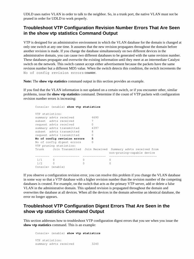
VTP is designed for an administrative environment in which the VLAN database for the domain is changed atonly one switch at any one time. It assumes that the new revision propagates throughout the domain beforeanother revision is made. If you change the database simultaneously on two different devices in theadministrative domain, you can cause two different databases to be generated with the same revision number.These databases propagate and overwrite the existing information until they meet at an intermediate Catalystswitch on the network. This switch cannot accept either advertisement because the packets have the samerevision number but a different MD5 value. When the switch detects this condition, the switch increments theNo of config revision errors counter.
Note: The show vtp statistics command output in this section provides an example.
If you find that the VLAN information is not updated on a certain switch, or if you encounter other, similarproblems, issue the show vtp statistics command. Determine if the count of VTP packets with configurationrevision number errors is increasing:
Console> (enable) show vtp statistics
VTP statistics:summary advts received 4690subset advts received 7request advts received 0summary advts transmitted 4397subset advts transmitted 8request advts transmitted 0No of config revision errors 5No of config digest errors 0VTP pruning statistics:Trunk Join Transmitted Join Received Summary advts received from non−pruning−capable device−−−−−−−− −−−−−−−−−−−−−−− −−−−−−−−−−−−− −−−−−−−−−−−−−−−−−−−−−−−−−−− 1/1 0 0 0 1/2 0 0 0Console> (enable)
If you observe a configuration revision error, you can resolve this problem if you change the VLAN databasein some way so that a VTP database with a higher revision number than the revision number of the competingdatabases is created. For example, on the switch that acts as the primary VTP server, add or delete a falseVLAN in the administrative domain. This updated revision is propagated throughout the domain andoverwrites the database at all devices. When all the devices in the domain advertise an identical database, theerror no longer appears.
Troubleshoot VTP Configuration Digest Errors That Are Seen in theshow vtp statistics Command Output
This section addresses how to troubleshoot VTP configuration digest errors that you see when you issue theshow vtp statistics command. This is an example:
Console> (enable) show vtp statistics
VTP statistics:summary advts received 3240

subset advts received 4request advts received 0summary advts transmitted 3190subset advts transmitted 5request advts transmitted 0No of config revision errors 0 No of config digest errors 2VTP pruning statistics:Trunk Join Transmitted Join Received Summary advts received from non−pruning−capable device−−−−−−−− −−−−−−−−−−−−−−− −−−−−−−−−−−−− −−−−−−−−−−−−−−−−−−−−−−−−−−− 1/1 0 0 0 1/2 0 0 0Console> (enable)
The general purpose of an MD5 value is to verify the integrity of a received packet and to detect any changesto the packet or corruption of the packet during transit. When a switch detects a new revision number that isdifferent from the currently stored value, the switch sends a request message to the VTP server and requeststhe VTP subsets. A subset advertisement contains a list of VLAN information. The switch calculates the MD5value for the subset advertisements and compares the value to the MD5 value of the VTP summaryadvertisement. If the two values are different, the switch increases the No of config digest errorscounter.
A common reason for these digest errors is that the VTP password is not configured consistently on all VTPservers in the VTP domain. Troubleshoot these errors as a misconfiguration or data corruption issue.
When you troubleshoot this problem, ensure that the error counter is not historical. The statistics menu countserrors since the most recent device reset or the VTP statistics reset.
Unable to Change the VTP Mode of a Switch from Server / Transparent
If the switch is a standalone (that is, not connected to the network), and you want to configure the VTP modeas the client, after reboot, the switch comes up either as a VTP server or VTP transparent, dependent upon theVTP mode of the switch before it was configured as the VTP client. The switch does not allow itself to beconfigured as a VTP client when there is no VTP server nearby.
OSPF Hellos Blocked in a VTP Domain
Open Shortest Path First (OSPF) Hellos can get blocked and the adjacency can be dropped if a switch in theVTP domain is changed from the server or client mode to transparent mode. This issue can occur if VTPpruning is enabled in the domain.
Use any of these options in order to resolve the issue:
Hard code the OSPF neighbors.• Disable VTP pruning in the domain.• Revert the VTP mode of the switch to server or client.•
SW_VLAN−4−VTP_USER_NOTIFICATION
This section talks about the commonly occuring variants of this error message:
%SW_VLAN−4−VTP_USER_NOTIFICATION : VTP protocol user notification: [chars]

%SW_VLAN−4−VTP_USER_NOTIFICATION: VTP protocol user notification: Version 1 devicedetected on [int] after grace period has ended
By default, the VLAN Trunking Protocol (VTP) Version on Cisco switches is Version 2 and is compatiblewith Version 1. This message is just a notification that indicates that there is a switch connected on portGig0/10 that runs VTP Version 1. Everything continues to work fine, unless you run IPX, and there is nothingharmful for the switch.
In order to resolve this issue, change the VTP version with these commands.
For Cisco IOS switches, use these commands:
Switch#vlan databaseSwitch(vlan)#vtp v2−mode
For CatOS switches, use this command:
Console> (enable) set vtp version 2 enable
%SW_VLAN−SP−4−VTP_USER_NOTIFICATION: VTP protocol user notification: MD5 digestchecksum mismatch on receipt of equal revision summary on trunk: [int]
In order to know more the cause and to resolve the issue, see the Troubleshoot VTP Configuration DigestErrors That Are Seen in the show vtp statistics Command Output section.
%SW_VLAN−4−VTP_USER_NOTIFICATION: VTP protocol user notification: Error detected inVTP Revision Number for VTP Domain Index [dec]
In order to know more the cause and to resolve the issue, see the Troubleshoot VTP Configuration RevisionNumber Errors That Are Seen in the show vtp statistics Command Output section.
Single Switchport Trunk That Allowed the vlan command Appears asMultiple Commands in the show running−config command Output
When the number of allowed VLANs extends past a certain number of characters, which is the defaultterminal width, the show running−config command wraps the line and adds the switchport trunk allowedvlan add command to the line. This is the way Cisco IOS handles long lists in the switchport trunk allowedvlan command.
Switch#configure terminalSwitch(config)#int fa3/30Switch(config−if)#switchport trunk allowed vlan 14, 105, 110, 115, 120, 125, 130−132, 140, 150, 155, 200, 210, 220, 222, 230, 232, 240, 301−309, 840, 860−862, 870, 880, 881, 884−886, 889, 896, 898, 411, 412, 413, 421
!−−− The previous command should be in a single line. It has been wrapped into three lines for proper formatting.
The output of show running−config looks similar to this:
Switch#show running−config | begin 3/30interface FastEthernet3/30 switchport switchport trunk allowed vlan 14,105,110,115,120,125,130−132,140,150,155,200 switchport trunk allowed vlan add 210,220,222,230,232,240,301−309,411−413,421 switchport trunk allowed vlan add 840,860−862,870,880,881,884−886,889,896,898

!
!−−− rest of output elided
You can also notice that the VLAN list has been order in ascending order and displayed in the output.
Remove VLAN 1 from the allowed list so you can disable VLAN 1 on any individual VLAN trunk port inorder to reduce the risk of spanning−tree loops or storms. When you remove VLAN 1 from a trunk port, theinterface continues to send and receive management traffic, for example, Cisco Discovery Protocol (CDP),Port Aggregation Protocol (PAgP), Link Aggregation Control Protocol (LACP), Dynamic Trunking Protocol(DTP), and VLAN Trunking Protocol (VTP) in VLAN 1.
The no form of the allowed vlan command resets the list to the default list, which allows all VLANs.
Internal VLAN Usage
All packets sent to the EARL must be prefixed by a VLAN ID, because that is the packet format the EARLexpects. Routed ports do not have a visible VLAN ID since one is not explicitly configured, so the switchborrows a VLAN from the pool of 4096 that it has. You can instruct the Catalyst 6500 series switch to start toborrow VLANs from the top, and descend from 4096, or from bottom, and ascend from 1006, with the use theglobal config mode vlan allocation policy command.
Switch(config)#vlan internal allocation policy {ascending | descending}
Thus it is normal behavior for internal VLAN to be utilized with routed or WAN interface.
Related Information
LAN Product Support• LAN Switching Technology Support• Technical Support & Documentation − Cisco Systems•
Contacts & Feedback | Help | Site Map© 2014 − 2015 Cisco Systems, Inc. All rights reserved. Terms & Conditions | Privacy Statement | Cookie Policy | Trademarks ofCisco Systems, Inc.
Updated: Jul 29, 2007 Document ID: 98155