troubleshooting Radiated emissions Using Low-Cost · PDF fileCISPR-22 Telecom Conducted...
12
10 INTERFERENCE TECHNOLOGY EMC DIRECTORY & DESIGN GUIDE 2011 testing & test equipment KENNETH WYATT, SR. Wyatt Technical Services Woodland Park, Colorado USA B ecause time-to-market and budget factors often drive many of today’s high-tech designs, electromagnetic compatibility (EMC) issues often surface at the last moment in the design cycle, poten- tially delaying product introductions. Very often, simple troubleshooting techniques can identify issues early when the cost of implementation is substantially lower and design improvements may be made with less impact on schedules. is article describes a number of simple probing tools and techniques useful in reducing the radiated emissions (RE) of a product that will better prepare it for a successful radiated emission compliance test. INTRODUCTION ere are usually five key threats that com- prise most electromagnetic compatibility (EMC) problems: radiated emissions, elec- trostatic discharge (ESD), susceptibility to RF fields, power disturbances and internal crosstalk. Of these, radiated emissions (RE) can be the most difficult test for a product to pass. Because emissions limits are es- tablished worldwide, products that don’t meet the limits may not be placed on the market. e best way to achieve compliance is through proper product design, but often these design techniques are not taught in universities, nor are these techniques fully understood by many experienced engineers. e result is that EMC is considered “black magic” and many products must be tested repeatedly through a system of trial and er- ror, in order to finally achieve compliance. is is unfortunate, because the emis- sions a product may produce is easily understood if the designer considers that high-frequency currents in circuit loops tend to broadcast these emissions. ese circuit loops may be in the form of printed circuit traces (differential-mode currents) or cables connecting two subsystems (common-mode currents). ere may also be combinations of these phenomenon, as well as poor printed circuit board layout practices. e circuit and system design of a product usually falls within the domain of the electronic engineer. e other con- sideration is the shielding properties of the product, which typically falls within the domain of the mechanical engineer. Ideally, these two must work together as a team to address the whole product in order to be successful in addressing EMC. TROUBLESHOOTING PHILOSOPHY In troubleshooting any radiated emission problem, it’s useful to think of the problem in the form of a “source-path-receptor” model. See Figure 1. Typically, the source of radiated emis- Troubleshooting Radiated Emissions Using Low-Cost Bench-Top Methods Figure 1. Source-path-receptor model.
Transcript of troubleshooting Radiated emissions Using Low-Cost · PDF fileCISPR-22 Telecom Conducted...

10 interference technology emc Directory & Design guiDe 2011
testing & test equipment TroubleshooTing radiaTed emissions
kenneth wyatt, SR.Wyatt technical services Woodland Park, colorado usA
Because time-to-market and budget factors often drive many of today’s high-tech designs, electromagnetic
compatibility (EMC) issues often surface at the last moment in the design cycle, poten-tially delaying product introductions. Very often, simple troubleshooting techniques can identify issues early when the cost of implementation is substantially lower and design improvements may be made with less impact on schedules. This article describes a number of simple probing tools and techniques useful in reducing the radiated emissions (RE) of a product that will better prepare it for a successful radiated emission compliance test.
IntRODUCtIOnThere are usually five key threats that com-prise most electromagnetic compatibility (EMC) problems: radiated emissions, elec-trostatic discharge (ESD), susceptibility to RF fields, power disturbances and internal crosstalk. Of these, radiated emissions (RE) can be the most difficult test for a product
to pass. Because emissions limits are es-tablished worldwide, products that don’t meet the limits may not be placed on the market. The best way to achieve compliance is through proper product design, but often these design techniques are not taught in universities, nor are these techniques fully understood by many experienced engineers. The result is that EMC is considered “black magic” and many products must be tested repeatedly through a system of trial and er-ror, in order to finally achieve compliance.
This is unfortunate, because the emis-sions a product may produce is easily understood if the designer considers that high-frequency currents in circuit loops tend to broadcast these emissions. These circuit loops may be in the form of printed circuit traces (differential-mode currents) or cables connecting two subsystems (common-mode currents). There may also be combinations of these phenomenon, as well as poor printed circuit board layout practices. The circuit and system design of a product usually falls within the domain of the electronic engineer. The other con-sideration is the shielding properties of the product, which typically falls within the domain of the mechanical engineer. Ideally, these two must work together as a team to address the whole product in order to be successful in addressing EMC.
tROUBLeShOOtInG PhILOSOPhyIn troubleshooting any radiated emission problem, it’s useful to think of the problem in the form of a “source-path-receptor” model. See Figure 1.
Typically, the source of radiated emis-
troubleshooting Radiated emissions Using Low-Cost Bench-top Methods
Figure 1. Source-path-receptor model.

Absorbing Clamp30 to 1000 MHz
LISNs10 KHz to 1 GHz, 5 to 350 Amperes
TEM CellsDC to 2000 MHz
EM Injection Clamp10 KHz to 1000 MHz
Injection Probes - Clamp-on,CW and Pulse 10 KHz to 2000 MHz,Internal Diameters from 32 to 66mm,50 to 750 Watts
Providing a complete family of EMC Testing solutions
Applications Mil-Std 461/462, CISPR, FCC, VDE, IEC 1000-4-6, -7, -8, -9, -10, ESD, HIRF, TREOP Bellcore, SAE J15447, RTCA DO-160
CISPR-22 Telecom Conducted Emission Test Accessories
Fischer Custom Communications, Inc.S E R V I N G T H E E M C C O M M U N I T Y S I N C E 1 9 7 1
20603 Earl Street ■ Torrance, California 90503 USA ■ Telephone (310) 303-3300 Fax (310) 371-6268 ■ E-mail sales @fischercc.com ■ www.fischercc.com
IEC 1000-4-8 Test Equipment
Coupling Decoupling Networks150 KHz to 230 MHz / Power lin 15 to 200Amperes, Balanced line / Coaxial /Shielded Multipin / Unshielded Multipin
Monitor Current ProbesSurface & Clamp-on, 1 Hz to 5 GHzInternal Diameters 5 mm to 1 meter
12 interference technology emc Directory & Design guiDe 2011
testing & test equipment TroubleshooTing radiaTed emissions
sions is a high-frequency crystal oscillator or other high-frequency, fast-edged, high-current signal. ASICs, FPGAs and A/D or D/A converters may also generate these high-frequency harmonics. Sources of common-mode currents include simultaneous switching noise (SSN) through com-mon impedances, routing of clock traces over gaps in return planes and unbalanced physical structures or resonances in PC boards or enclosures.
The “path” is the coupling mechanism, or the means, by which the high-frequency energy is coupled to the radiat-ing element (enclosure slot, cable, etc.). This may include conducted, radiated, inductive or capacitive couplings.
The “receptor”, in most cases, is the EMI receiver at the test site with specified emission limits, but in the real world could include interference to radio, television, or commu-nication systems.
By using simple measurement probes, it should be pos-sible to identify the source or sources. Once the sources are identified, the path or coupling mechanism must be identified and fixed. What’s difficult is that there may be multiple sources and coupling mechanisms to identify and fix, before passing results are achieved. In addition, if a fix is improperly installed, the emission can actually get worse! That’s probably why the field of EMC is considered so mysterious.
By using a structured approach, the troubleshooting
phase should go smoothly. Generally, you’ll want to diag-nose the issues first – then try various fixes. Leave these fixes installed as you continue the troubleshooting process. By setting up a simple antenna and EMI receiver or spectrum analyzer a fixed distance away (1 to 3m) from where you’re troubleshooting you can monitor your results real-time. Note, however, a 10 dB drop in emissions at 1m does not necessarily indicate the same drop in the measurement chamber, due to near-field effects.
Identify the sourcesThe first step should always be to identify the likely sources. If you’re failing at 300 or 500 MHz, for example, are these the third or fifth harmonics of a 100 MHz clock oscilla-tor? How about the memory clocking? Generally memory address and data busses are fairly random. The exception would be the A0 or D0 line, which is clocking at a relatively non-random rate. What about clock lines to ASICs or FP-GAs? If you have multiple crystal oscillators, which could be the cause of a particular harmonic, applying freeze spray on one, then the other, can often identify the offending oscillator.
FrequencyThe frequency is key to any radiated emission problem. As a quick rule of thumb, the higher the frequency, the more


14 interference technology emc Directory & Design guiDe 2011
testing & test equipment TroubleshooTing radiaTed emissions
likely the coupling path is radiated. The lower the frequency, the more likely the path is conducted. In fact, the common break frequency during compliance testing is 30 MHz. Below that, we measure conducted emissions (CE) – above that we measure RE. If your product uses a high-frequency crystal
oscillator with fast edge speeds, the harmonic content can be estimated with the formula in Equation 1.
Equation 1. Maximal RE frequency estimate, where f = EMI frequency (Hz) and tr = risetime (seconds).
For example, with 1 nsec logic, the harmonic content may be centered around 300 MHz. Another rule of thumb is that for frequencies below about 300 MHz, the problem is most likely due to common-mode emissions from cables and above that; the problem is most likely radiation from slots or seams in the metal chassis or circuit board radiation.
DimensionsThe dimensions of physical structures are also an important factor in troubleshooting an emissions problem. Recall that the wavelength (m) of a resonant wire at frequency, f, in free space is:
Equation 2. Wavelength of a wire in free space, where c = speed of light in m/s and f = frequency in Hz.
The dimensions of physical structures, like circuit boards, must be reduced by the velocity factor of the board mate-
Figure 2. Examples of DIY antennas for radiated emissions troubleshooting. The “rabbit ears” are resonant from 65 to 200 MHz, while the bowtie works well from 300 to 800 MHz. I installed a television-style balun to better match to 50-ohm coax for the bowtie.
Put us to the testSM
795 Marconi Avenue • Ronkonkoma, NY 11779 TEL: (631) 737-1500 • FAX: (631) 737-1497 • www.retlif.com
Additional Locations in New Hampshire, North Carolina, Pennsylvania & Washington D.C.
On-site, or in one of our three laboratories, Retlif is ready, willing and able to provide EMC/EMI testing and engineering support.
We’re ready…with state of the art equipment in all our labs.We’re willing…with a dedicated, highly trained staff.
We’re able…with in-house engineering support.
Count on Retlif’s testing leadership for EMC and Lightning testing services tonational and international standards.
Trust your equipment and systems to Retlif for shielded Effectiveness testing,EMP, high level radiated susceptibility testing and low noise level emissionstesting. Leading military, aerospace, commercial and industrial companieshave, for over 30 years.
� FULLY ACCREDITED TO OVER 350 EMC TEST METHODS.
8483 Retlif EMC_ITEM ad 2/3/11 2:36 PM Page 1

CPI: Powering your world.
For more information please contact:Communications & Power Industries Canada,Inc.45 River Drive, Georgetown, Ontario,Canada L7G 2J4
For Sales offices worldwide please e-mail: [email protected] look us up on the Web at: www.cpii.com/emc
TWTAs for EMC applications
1.0 -18.0 GHz up to 1000 W CW (10 kW available over select bands)
18.0-40.0 GHz up to 150 W (2.0 kW over select bands)
40.0 – 50.0 GHz up to 80 W
Full Pulsed Amplifier Suites to 8 kW (megawatts pulsed power capability)
Meet the new automotive and military EMC standards with CPI high-powered TWT amplifiers.EMC facilities worldwide depend on CPI amplifiers for superior performance, reliability, and quality. CPI has a proven track record of consistent performance, service, and support. For EMC testing, CPI is the only manufacturer of both the TWT and the amplifier, ensuring quality designs and smooth operation. CW and pulsed amplifiers are available from 1 to 95 GHz, with power levels exceeding 2 kW over selected frequencies.
C
M
Y
CM
MY
CY
CMY
K
CPI_EMC_WORLD_1page.pdf 1 10/1/09 8:45 AM
16 interference technology emc Directory & Design guiDe 2011
testing & test equipment TroubleshooTing radiaTed emissions
rial (example, 4.7 for FR4 circuit boards). However, typical cables, such as USB or video, are approximately 1m long and can be considered as being in free space. Wires or slots may
resonate strongly at multiples of a quarter wavelength. For example, a 1m long cable has a full-wave resonance of 300 MHz, but may also radiate strongly at 150 and 75 MHz. Slots or seams of 8 to 15 cm may resonate in the area of 500 to 800 MHz. As a general rule of thumb, radiating cables or chassis slots of 1/ 20th wavelength or greater, start to become significant radiating elements (or antennas) for RE.
USeFUL tOOLS antennas The antenna you select should ideally be somewhere near resonance for the frequencies of concern, however, it’s not really that critical for troubleshooting purposes. So long as the antenna is fixed in length and fixed in place on the bench, you’ll receive consistent results. During trouble-shooting, it’s more important to know whether the fix is “better” or “worse” or “no change” and as long as the test setup doesn’t change, the results should be believable.
Now, EMC antennas are not inexpensive, as you might imagine, so for general troubleshooting, I tend to use a couple inexpensive television antennas - a pair of “rabbit ears” and a UHF “bowtie” (with TV balun to match 50-ohm coax). See Figure 2. If the workbench is wooden, I’ll extend the antenna to approximate resonance (if possible) and tape it down to the bench with duct tape. If the bench is metal-lic, I’ll find a non-conductive support and position it some distance away from the bench. I usually use a test distance of about a meter, but as long as you can see the product’s harmonics on a spectrum analyzer, you’ll be able to deter-mine your progress. Sometimes I need to insert a low-noise wide-band preamp between antenna and analyzer.
Now, obviously, ambient signals from broadcast radio, television mobile phones and two-way radio services will tend to interfere with observing the product harmonics. You may need to bring the antenna closer or set up the troubleshooting measurement in a basement or building interior away from outside windows. I usually record the known harmonics of concern using an H-field probe or by bringing the measurement antenna in close and then try to characterize them in relation to other nearby ambient signals.
ProbesThere are a variety of useful probes that may be used to troubleshoot RE problems; E-field, H-field and current probes.1 All are easily made in the lab or are available from several manufacturers. An E-field probe may be made by extending the center conductor about 0.5 cm from a sec-tion of semi-rigid coax or high-quality flexible coax; then attaching a coax connector to the other end. Shorting of the probe to circuit traces may be avoided by wrapping insulating tape around the end. A useful H-field probe may be fashioned by looping the center conductor around and soldering it to the shield to form a small loop of 0.5 to 5 cm in diameter - the larger the loop, the more sensitivity. A better
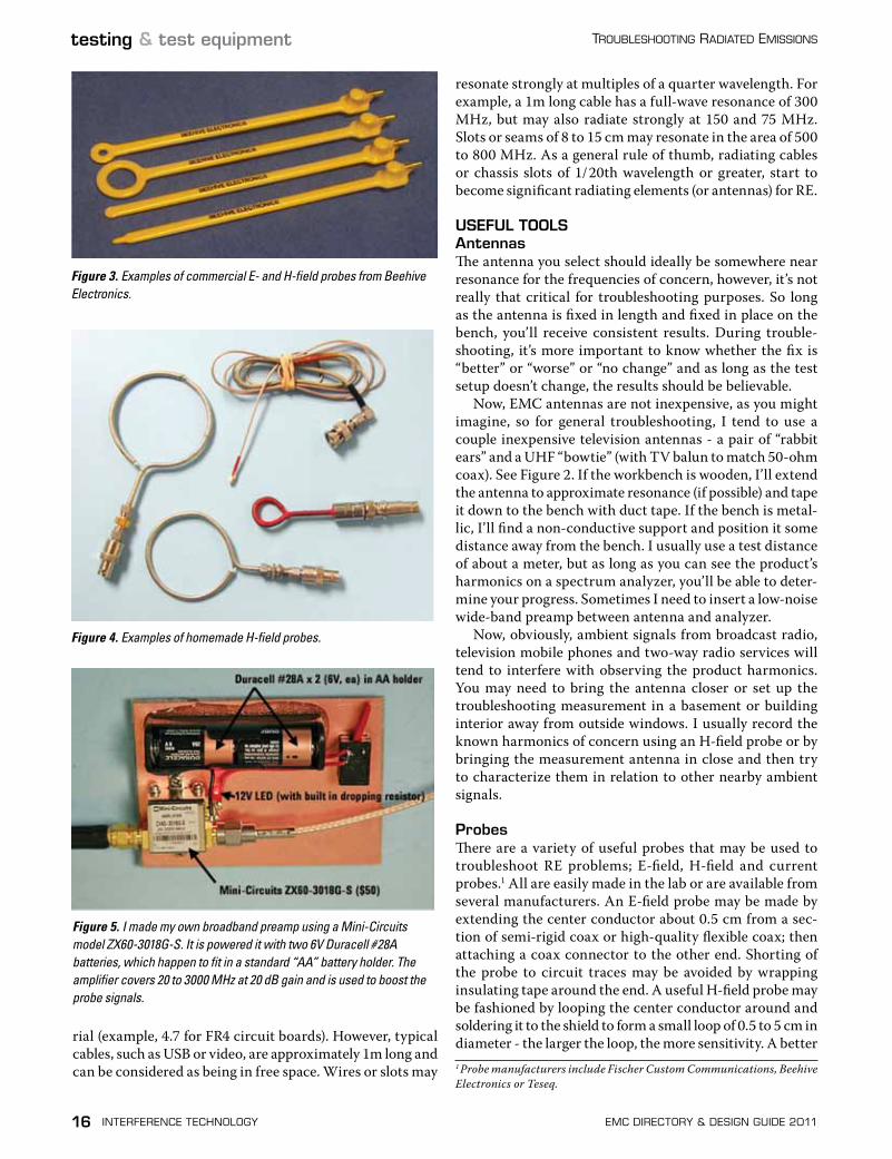
Figure 3. Examples of commercial E- and H-field probes from Beehive Electronics.
Figure 4. Examples of homemade H-field probes.
Figure 5. I made my own broadband preamp using a Mini-Circuits model ZX60-3018G-S. It is powered it with two 6V Duracell #28A batteries, which happen to fit in a standard “AA” battery holder. The amplifier covers 20 to 3000 MHz at 20 dB gain and is used to boost the probe signals.
1 Probe manufacturers include Fischer Custom Communications, Beehive Electronics or Teseq.

903 South Second Street • Ronkonkoma, NY 11779Tel: 631-467-8400 • Fax: 631-467-8558 • E mail: [email protected] • www.ifi.com
Freq Min Pwr Min SatModel Range Out GainNumber (MHz) (Watts) (dB)
M/TCCX/SCCX Series • .01-220 MHzSCCX300 .01-220 300 55SCCX500 .01-220 500 57M404 .01-220 500 57M406 .01-220 1000 60TCCX2000 .01-220 2000 63TCCX2200 .01-220 2200 63TCCX2500 .01-220 2500 64
CMX/SMX Series • .01-1000 MHzSMX301 .01-1000 300/100 55/50SMX302 .01-1000 300/200 55/53SMX303 .01-1000 300/300 55/55SMX501 .01-1000 500/100 57/50SMX502 .01-1000 500/200 57/53SMX503 .01-1000 500/300 57/55CMX10001 .01-1000 1000/100 60/50CMX100010 .01-1000 1000/1000 60/60
Freq Min Pwr Min SatModel Range Out GainNumber (MHz) (Watts) (dB)
SMCC Series • 200-1000 MHz
SMCC350 200-1000 350 55SMCC600 200-1000 600 58SMCC1000 200-1000 1000 60SMCC2000 200-1000 2000 63
SMC Series • 80-1000 MHzSMC250 80-1000 250 54SMC500 80-1000 500 57SMC1000 80-1000 1000 60
SMX-CMX Series • .01-1000 MHzSMX100 .01-1000 100 50SMX200 .01-1000 200 53SMX500 .01-1000 500 57
SVC-SMV Series • 100-1000 MHzSVC500 100-500 500 57SMV500 500-1000 500 57
Solid StateTetrode Tube and
Combination Amplifiers
Microwave Solid Stateand TWT Amplifiers
Solid StateAmplifiers
Freq Min Pwr Min SatModel Range Out GainNumber (GHz) (Watts) (dB)T-200 Series • 200-300 Watts CW 1-21.5 GHz
T251-250 1-2.5 250 54T82-250 2-8 250 54T188-250 7.5-18 250 54T2118-250 18.0-21.7 250 54
T-500 Series • 500 Watts CW 1-18 GHzT251-500 1-2.5 500 57T7525-500 2.5-7.5 500 57T188-500 7.5-18 500 57
MMT Series • 5-150 Watts, 18-40 GHzT2618-40 18-26.5 40 46T4026-40 26.5-40 40 46S/T-50 Series • 40-60 Watts CW 1-18 GHz
S21-50 1-2 50 47T82-50 2-8 50 47T188-50 8-18 50 47
INSTRUMENTS FOR INDUSTRYVisit IFI.com for additional amplifier models and products.
New ad 8.35x10.875 sept 08:New ad 8.35x10.875 1-14-05 9/12/08 2:35 PM Page 1
Booth 804
IFI-1.indd 1 6/16/2010 5:17:13 PM

18 interference technology emc Directory & Design guiDe 2011
testing & test equipment TroubleshooTing radiaTed emissions
H-field probe design uses semi-rigid coax to form the loop (see examples in Figures 3 and 4). Occasionally, I’ll need to amplify the harmonic signals and so use a DIY broadband preamplifier as shown in Figure 5. Beehive Electronics also makes a low-cost amplifier.
tROUBLeShOOtInG StePSLocating internal sourcesConnect your probe to the input of an EMI receiver or spectrum analyzer to display the harmonics as the probe is brought into close contact with the circuit traces or chas-sis slots. Depending on the diameter of your H-field probe, you may need to use a broadband preamplifier between the probe and analyzer.2
Generally, once you are finished mapping out your sources, you should start with the lower harmonics and work upwards. Often, lower-frequency sources will cause significant high-frequency harmonics, depending upon the rise time. By fixing the low-frequency source, you’ll often resolve the high-frequency harmonics, as well. Next, check cables and then the enclosure.
Cables Check your cables next, as they are often the worst offend-ers. Moving a “hot” cable will alter the RE levels. I usually unplug all cables; then try plugging each one in individually to find all that are radiating. Remember that there may be more than one bad cable! Snapping a ferrite choke around the base of the cable will probably help as an interim fix. I’ve found that most cable emissions are very likely due to poor grounding to the enclosure at the I/O connector.
Cable common-mode currents may also be measured directly versus frequency with a current probe.3 Use of cur-rent probes usually works better than antennas, because they tend to pick up fewer ambient signals due to their e-field shield. Clamp the probe around the cable in question and move it back and forth to maximize the readings – then fix it in place while you apply potential fixes.
You can make your own current probe or purchase com-mercial versions. The advantage of commercial versions is that they can open up and snap around a cable. Examples of my DIY probe is shown in Figure 7, while commercial versions are shown in Figure 8.
It is possible to predict whether a particular cable will pass or fail by measuring the CM current at the offending frequency, solving for Ic (Figure 11 and Equation 3 on the next page) and plugging this into Equation 4 to solve for the field level in V/m. The length of the cable is L and the offend-ing harmonic frequency is f. Use a test distance of either 3 or 10m to predict the outcome at those test distances.
Figure 6. Use of simple H-field probes to locate emission sources.
Figure 7. Examples of DIY current probes. These photos were taken prior to installing the E-field shield by wrapping a layer of copper tape over the windings, leaving a small gap around the inside of the probe. 14 turns of Teflon-insulted wire wound around a Würth Electronik #74270097 ferrite core (4W620 material) was used, which is useful from 10 to 1000 MHz.
Figure 8. Examples of commercial current probes.
2 I made my own broadband preamp using a MiniCircuits model ZX60-3018G-S, which covers 20 to 3000 MHz at 18-23 dB gain and 2.7 dB noise figure. It sells for USD 50. 3Commercial current probes are available from Fischer Custom Commu-nications, Teseq or Solar Electronics, as well as many others.

WyaT T
interferencetechnology.com interference technology 19
testing & test equipment
Figure 9. A lack of solid ground can allow CM currents generated inside the product to flow out the I/O cable and radiate – usually causing RE failures. The included graph shows poor margins to the CISPR 11 Class A 3m RE limit (for ISM products, in this case). ITE products, such as PCs and printers have a limit 10 dB lower.
Test setup:Current probe on USB cable. Connection between connector ground shell and chassis enclosure made with screwdriver blade.
Some harmonics dropped by 10-15 dB!
Before After
Looking from 500 to 1000 MHz
Figure 10. Cables should be tested individually. Here, I have a current probe clamped around the cable under test and am monitoring the harmonics with a simple hand-held spectrum analyzer.4 As I ground the connector shell to the chassis with the screwdriver blade, the harmonics are reduced 10 to 15 dB!
Note a lack of good connection between chassis enclosure and connector ground.
LAN conn needs gnd shell.
4 The handheld spectrum analyzer being used for the cable test is made by Thurlby Thander Instruments. It sells for approximately USD 1995 and covers 1 MHz to 2.7 GHz.

20 interference technology emc Directory & Design guiDe 2011
testing & test equipment TroubleshooTing radiaTed emissions
Equation 3. Calculation of Ic given the measured V and Zt (from Figure 11). Next, plug Ic into Equation 4 to calculate the predicted E-field
emission level in V/m. Converting this to dBuV/m will indicate a pass or fail due to the cable being measured.
The equation for calculating the emission level in volts/meter for a CM signal is shown below in Equation 4.
Equation 4. Field level (V/m) due to CM current, where f = frequency (Hz), L = length of the wires (m) and d = the measurement distance (typically 3m or 10m).
Slots & seams Once the cables and associated I/O connectors are ad-dressed, it’s time to probe for radiation leakage through slots or seams in the chassis. Remember, that the length of the slot or seam is important. Any seam with leakage whose effective length is longer than 1/ 20th of a wavelength at the harmonic of concern has the potential to be an effective ra-diator. For example, a slot of 2.5 cm can just start radiating harmonics at 1000 MHz. I use a permanent marking pen to record the areas of leakage and frequencies of concern from every seam/slot on the enclosure.
Once these are marked, I’ll carefully cover over all the openings with copper tape and re-measure the RE levels. Keeping an eye on the RE levels, I’ll start removing the tape piece-by-piece to determine which slots or seams are
Figure 11. Transfer impedance (Zt) graph of a typical current probe (courtesy of Fischer Custom Communications). The x-axis is frequency, while the y-axis is dB . Use this to calculate the value of Ic, given the measured voltage at the probe terminals V(dBuV) and Zt.
WyaT T
interferencetechnology.com interference technology 21
testing & test equipment
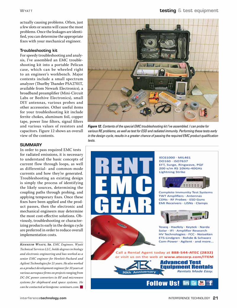
Figure 12. Contents of the special EMC troubleshooting kit I’ve assembled. I can probe for various RE problems, as well as test for ESD and radiated immunity. Performing these tests early in the design cycle, results in a greater chance of passing the required EMC product qualification tests.
actually causing problems. Often, just a few slots or seams will cause the most problems. Once the leakages are identi-fied, you can determine the appropriate fixes with your mechanical engineer.
troubleshooting kitFor speedy troubleshooting and analy-sis, I’ve assembled an EMC trouble-shooting kit into a portable Pelican case, which can be wheeled right to an engineer’s workbench. Major contents include a small spectrum analyzer (Thurlby Thander PSA2701T, available from Newark Electronics), a broadband preamplifier (Mini-Circuit Labs or Beehive Electronics), small DIY antennas, various probes and other accessories. Other useful items for your troubleshooting kit include ferrite chokes, aluminum foil, copper tape, power line filters, signal filters and various values of resistors and capacitors. Figure 12 shows an overall view of the contents.
SUMMaRyIn order to pass required EMC tests for radiated emissions, it is necessary to understand the basic concepts of current f low through loops, as well as differential- and common-mode currents and how they’re generated. Troubleshooting an existing design is simply the process of identifying the likely sources, determining the coupling paths through probing, and applying temporary fixes. Once these fixes have been applied and the prod-uct passes, then the electronic and mechanical engineers may determine the most cost-effective solutions. Ob-viously, troubleshooting or character-izing products early in the design cycle are preferred in order to reduce overall implementation costs.
Kenneth Wyatt, Sr. EMC Engineer, Wyatt Technical Services LLC, holds degrees in biology and electronic engineering and has worked as a senior EMC engineer for Hewlett-Packard and Agilent Technologies for 21 years. He also worked as a product development engineer for 10 years at various aerospace firms on projects ranging from DC-DC power converters to RF and microwave systems for shipboard and space systems. He can be contacted at [email protected]. n