TROUBLESHOOTING GUIDE FOR CNC MACHINES1 TROUBLESHOOTING GUIDE FOR CNC MACHINES DIESEL LOCO...
26
1 TROUBLESHOOTING GUIDE FOR CNC MACHINES DIESEL LOCO MODERNISATION WORKS, PATIALA An ISO 9001, ISO 14001, IS 18001, ISO 50001, 5S & GreenCo Certified Organization
Transcript of TROUBLESHOOTING GUIDE FOR CNC MACHINES1 TROUBLESHOOTING GUIDE FOR CNC MACHINES DIESEL LOCO...

1
TROUBLESHOOTING GUIDE FOR CNC MACHINES
DIESEL LOCO MODERNISATION WORKS, PATIALA An ISO 9001, ISO 14001, IS 18001, ISO 50001, 5S & GreenCo Certified Organization

2
INDEX
S.N Topic Page No. 1 GENERAL TROUBLESHOOTING 03-09
2 TROUBLE SHOOTING FOR THREE PHASE VOLTAGE STABILIZERS 10-11
3 HYDRAULIC SYSTEMS TROUBLE SHOOTING 12-14
4 PREVENTIVE MAINTENANCE SCHEDULE 15-24
5 RESOURCES AND SPARES FOR CNC MACHINES 25-26
3
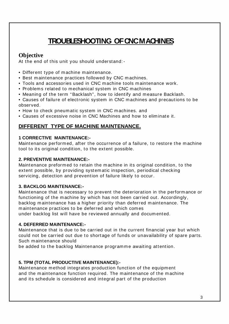
TROUBLESHOOTING OF CNC MACHINES
Objective At the end of this unit you should understand:- • Different type of machine maintenance. • Best maintenance practices followed by CNC machines. • Tools and accessories used in CNC machine tools maintenance work. • Problems related to mechanical system in CNC machines • Meaning of the term “Backlash”, how to identify and measure Backlash. • Causes of failure of electronic system in CNC machines and precautions to be observed. • How to check pneumatic system in CNC machines. and • Causes of excessive noise in CNC Machines and how to eliminate it. DIFFERENT TYPE OF MACHINE MAINTENANCE. 1 CORRECTIVE MAINTENANCE:- Maintenance performed, after the occurrence of a failure, to restore the machine tool to its original condition, to the extent possible. 2. PREVENTIVE MAINTENANCE:- Maintenance preformed to retain the machine in its original condition, to the extent possible, by providing systematic inspection, periodical checking servicing, detection and prevention of failure likely to occur. 3. BACKLOG MAINTENANCE:- Maintenance that is necessary to prevent the deterioration in the performance or functioning of the machine by which has not been carried out. Accordingly, backlog maintenance has a higher priority than deferred maintenance. The maintenance practices to be deferred and which comes under backlog list will have be reviewed annually and documented. 4. DEFERRED MAINTENANCE:- Maintenance that is due to be carried out in the current financial year but which could not be carried out due to shortage of funds or unavailability of spare parts. Such maintenance should be added to the backlog Maintenance programme awaiting attention. 5. TPM (TOTAL PRODUCTIVE MAINTENANCE):- Maintenance method integrates production function of the equipment and the maintenance function required. The maintenance of the machine and its schedule is considered and integral part of the production

4
schedule and the machine tools is maintained with the least disturbance to the production activity. Such maintenance schedules are well planned and leads to overall productivity of the plant and the equipment.
SYSTEM AND SUB SYSTEMS OF CNC MACHINES. Various functions of CNC machines are executed with the help of the following systems and sub systems. 1. Mechanical systems. 2. Electronic Systems (CNC and drives) 3. Work holding systems. 4. Tool clamping systems. 5. Lubrication systems. 6. Coolant systems. 7. Hydraulic systems. 8. Pneumatic systems, and 9. Chip conveying systems. FUNCTIONS OF MECHANICAL SYSTEMS. Primary function of the mechanical systems in CNC machines are similar to conventional machines. CNC Lathe machine consists of the following sub systems. 1. Headstock. 2. Axis assembly. 3. Tool post, and 4. Tailstock CNC milling machine consists of following sub systems. 1. Axis assembly. 2. tool magazine, and 3. Bed BEST MAINTENANCE PRACTICES. Following are some of the best maintenance practices to be adhered to while carrying out maintenance of CNC machines. 1. Execution of maintenance activities as per TPM (Total Productive Maintenance) Chart. 2. “Solving” the “Cause” of the problem and not the “Symptom” 3. Use of “Right” tools, fixtures, equipment and spares. 4. Understanding the accuracy class of bearing, grade of oil and their correct specifications. 5. Understanding the working of the machine tools by studying the manuals, and circle diagram supplied by the machine manufacturers. 6. Use of flow chart/cause and defect diagrams and the breakdown history for
5
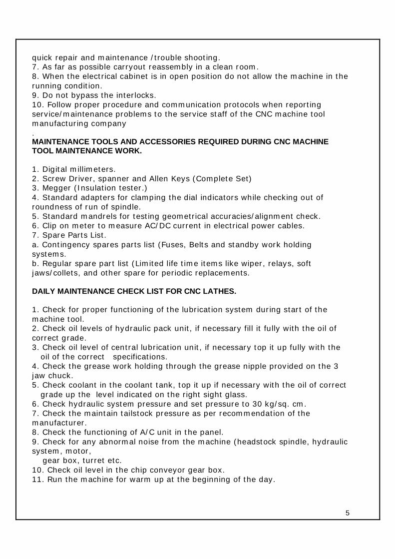
quick repair and maintenance /trouble shooting. 7. As far as possible carryout reassembly in a clean room. 8. When the electrical cabinet is in open position do not allow the machine in the running condition. 9. Do not bypass the interlocks. 10. Follow proper procedure and communication protocols when reporting service/maintenance problems to the service staff of the CNC machine tool manufacturing company . MAINTENANCE TOOLS AND ACCESSORIES REQUIRED DURING CNC MACHINE TOOL MAINTENANCE WORK. 1. Digital millimeters. 2. Screw Driver, spanner and Allen Keys (Complete Set) 3. Megger (Insulation tester.) 4. Standard adapters for clamping the dial indicators while checking out of roundness of run of spindle. 5. Standard mandrels for testing geometrical accuracies/alignment check. 6. Clip on meter to measure AC/DC current in electrical power cables. 7. Spare Parts List. a. Contingency spares parts list (Fuses, Belts and standby work holding systems. b. Regular spare part list (Limited life time items like wiper, relays, soft jaws/collets, and other spare for periodic replacements. DAILY MAINTENANCE CHECK LIST FOR CNC LATHES. 1. Check for proper functioning of the lubrication system during start of the machine tool. 2. Check oil levels of hydraulic pack unit, if necessary fill it fully with the oil of correct grade. 3. Check oil level of central lubrication unit, if necessary top it up fully with the
oil of the correct specifications. 4. Check the grease work holding through the grease nipple provided on the 3 jaw chuck. 5. Check coolant in the coolant tank, top it up if necessary with the oil of correct
grade up the level indicated on the right sight glass. 6. Check hydraulic system pressure and set pressure to 30 kg/sq. cm. 7. Check the maintain tailstock pressure as per recommendation of the manufacturer. 8. Check the functioning of A/C unit in the panel. 9. Check for any abnormal noise from the machine (headstock spindle, hydraulic system, motor, gear box, turret etc. 10. Check oil level in the chip conveyor gear box. 11. Run the machine for warm up at the beginning of the day.

6
CAUSES FOR THE FAILURE OF ELECTRONICS SYSTEMS IN THE MACHINE TOOLS. 1. Dust failing on the electronic components. 2. Corrosive fumes (coming from coolant interacting with the hot chips) 3. Oil/Coolant dripping through cables. 4. Condensation of moisture. 5. Insects. 6. Poor Ventilation. 7. Improper power supply. 8. Improper earthing. 9. Loose connections and bare control wirings. 10. Non conformance to EMI (Electro Magnetic Interference) guidelines. 1) PRECAUTION TO BE OBSERVED. 1. Ensure secure panel and pendant sealing. 2. Maintain gasket in the good condition. 3. Ensure proper orientation and direction of the exhaust fans. 4. Ensure proper sealing at the entry of the cables. 5. Maintain right temperature of the A/C systems. 6. Ensure that no insects and pests come near the machine tool. 7. Ensure periodic cleaning of the filters of A/C Systems. 8. Ensure periodic tightening of cable connections and avoiding bare wires. 9. Ensure Guidelines against EMI (Electro Magnetic Interference) as laid down
by. 2) ENSURE PROPER POWER SUPPLY 1. Ensure proper sequence and connections of isolation transformer, if installed. 2. Ensure proper rating of generators, if used. 3. Ensure that surge suppressor are installed on all switching/inductive devices. 4. Ensure proper rating of protective switchgears as per the recommendation by the manufacturer. 5. Ensure proper rating/cross section of cables as per the recommendation by the manufacturer. 6. Ensure switching sequence as per the recommendation of the manufacturer. 7. Do not mix, neutral and earth lines/wires. ENSURE PROPER EARTHING OF POINTS INDICATED BY THE MACHINE TOOL MANUFACTURER. 1. Do not loop earth wire between the electronic components. 2. Ensure proper cross section of the earth wire at all the points. 3. Ensure the earth resistance at the incoming terminals as less 1 Ohm. 4. In case, one earthing pit caters to more than one machine, form tree
structure. 5. Do not loop earthing between different machines.

7
6. Ensure proper surface, connectors and conductors for connections. 7. Ensure periodic maintenance of earthing pit. COMMON REASONS FOR FAILURE AND PREVENTIVE MAINTENANCE. 1. Ensure prevention of dust and coolant fumes in the control panels and
pendant. 2. Ensure proper setting of axis. 3. Ensure proper selection of motors. 4. Ensure proper bending/overhanging of connection belts. 5. Monitor periodically the vibrations on motors. DEVIATIONS FROM NORMAL PERFORMANCE IN CNC MACHINES. 1. Size variation 2. Taper formation. 3. ovality (out of roundness or run out) 4. Surface finish less than desirable. 5. Decreased tool life. 6. Stalling of machine tool spindle. FACTORS LEADING TO SIZE VARIATION. ASPECTS OF SZIE VARIATION 1. Constant variation from work piece to work piece. 2. Erratic variation from work piece to work piece. 3. Sudden variation and the dimensions remaining constant. 4. Occasional variation. CAUSES OF CONSTANT VARIATION. 1. Defective or improper functioning of encoder and coupling. 2. Slippage/Backlash (Identify and measure the value) 3. Slippage of coupling or belt. 4. Variation in coolant flow. CAUSES OF ERRATIC VARIATION FROM WORK PIECE TO WORK PIECE. • Cutting parameters change. • Present of Backlash. • Malfunctioning of encoder. • Slippage of couplings. • Improper turret clamping. • Wear out of guide ways • Wearout of ball screw bearing. • Wearout of ball screw locking nut. • Coolant flow not uniform. • Not maintaining optimum tailstock pressure.

8
• Belt damage. • Slippage of spindle belt. • Improper selection of coolant/lubricants. • Excessive run out of spindle. WHAT IS BACKLASH? It is a deviation from the actual position to the value displayed on the screen or simply the difference between physical position and the electronic reading. In the case of rotary encoder, position measurement is indirect unlike a linear scale. HOW TO IDENTIFY AND MEASURE BACKLASH ? 1. Mount the dial indicator on turret face and set zero on dial, reverse the axis movement and come back to the same point. The dial will now indicate the difference in value which indicate there is a backlash error. 2. How to compose for the backlash error? a. Check for ball screw preloading end nuts. b. Adjust belt tension. c. Prevent coupling slippage. POSSIBLE DEFECTS IN ENCODER OR COUPLING. 1. encoder coupling is loose. 2. Motor coupling is loose. 3. Encoder or axis belt worn out. ENCODER-FAILURE MODES. 1. Missing pulses (rotary incremental encoder) 2. Loose coupling. 3. Power cables running parallel with control cables. 4. Improper shielding of cables. 5. discontinuities in encoder cables. POSSIBLE DEFECTS IN GUIDE WAYS. 1. Improper flow of lubrication oil. 2. Wipers damaged. 3. Chips or dust entry into guideways. 4. Wearing out of jibs. 5. Wrong selection of lubrication oil. 6. Bellows with cracked openings. PROBLEMS RELATED MECHANICAL SYSTEMS IN THE MACHINE. (A) NOISE DURING SPINDLE RUNNING. Causes are:- 1. Misalignment of spindle belt. 2. Belt rubbing with the mounting bracket of the motor.

9
3. Misalignment of timer belt puller,. 4. Slackness of timer belt. 5. Failure or seizure of spindle bearing. 6. Failure of encoder assembly bearing. 7. Bolts of motors mounting and bolts of brackets are loose. 8. Bell crank lever screw rubbing with spindle. 9. Spindle pulley and motor pulley face run out or misalignment (always ensure that the spindle is run with be balanced tool holders) (B) EXCESSIVE SPINDLE RUN OUT. Causes are:- 1. Improper clamping of the test mandrel. 2. Improper spindle bore 3. Loosening of flange covers. 4. Excessive tensioning of spindle belt. 5. Belt misalignment. 6. Improper tightening of locknut after reconditioning and fitting. 7. Improper pull stud used. 8. Wearing of Collets. 9. Breakage of tool clamping disc springs. 10. Use of wrong tool holders. CHECKING OF PNEUMATIC SYSTEM. 1. Check for oil level in the lubrication unit. 2. Check for the proper air pressure in the regulator. 3. Check for proper air blast during tool changing. 4. Check for the moisture in pneumatic line (moisture in pneumatic lines should be avoided.) 5. Air leakage (this may be due to clogging of filters)
10
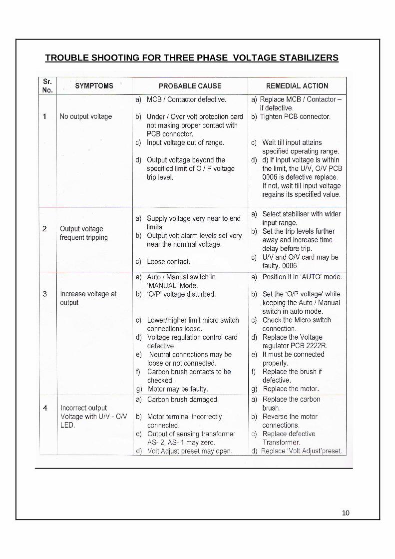
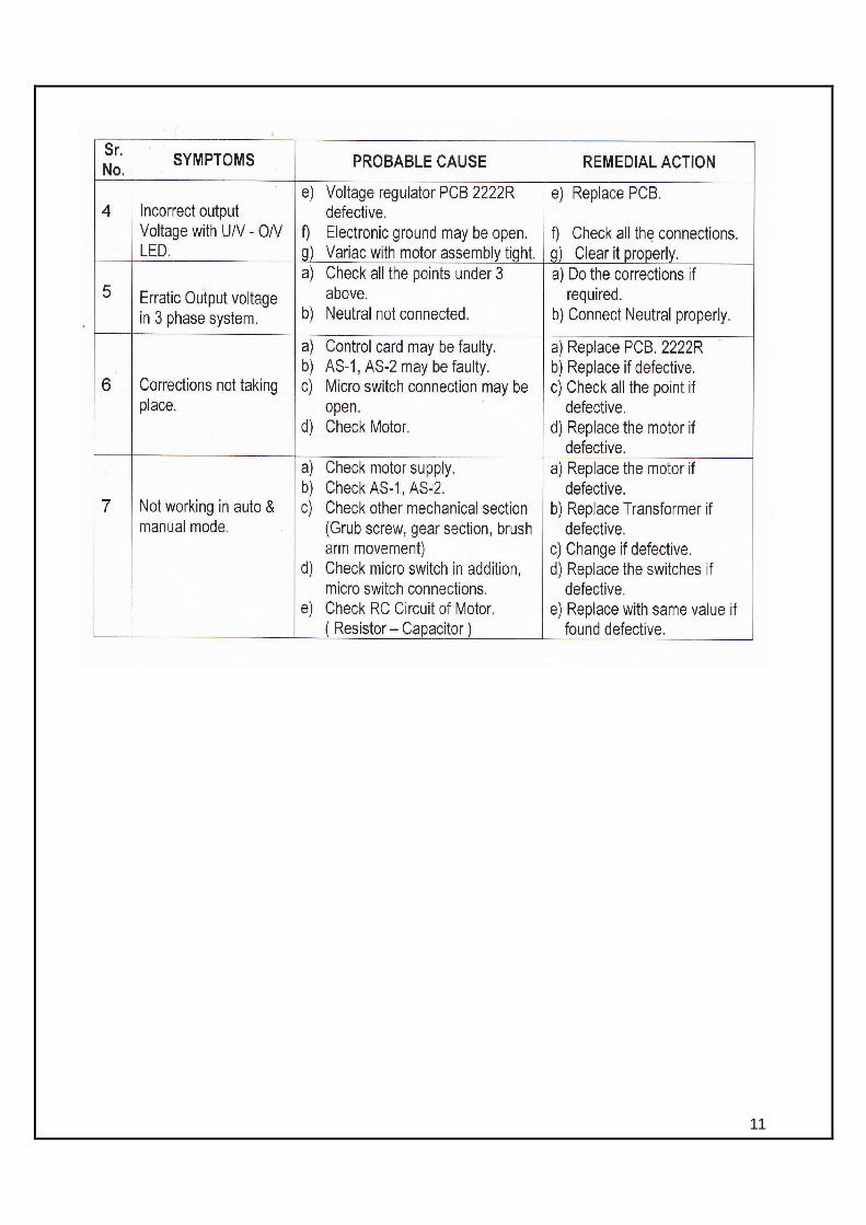
TROUBLE SHOOTING FOR THREE PHASE VOLTAGE STABILIZERS
11
12
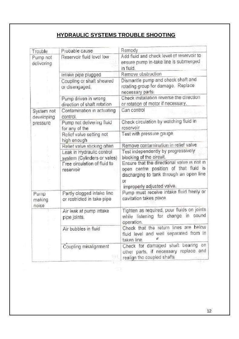
HYDRAULIC SYSTEMS TROUBLE SHOOTING

13

14

15
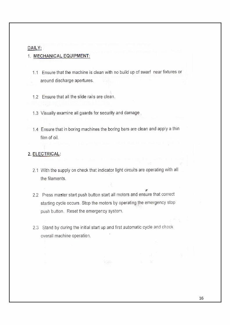
16

17

18
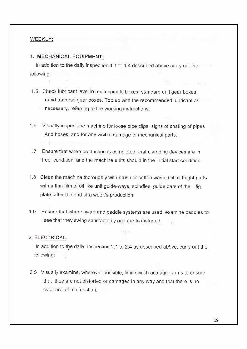
19

20

21

22

23
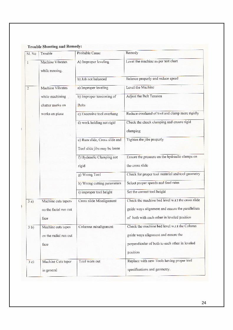
24
25
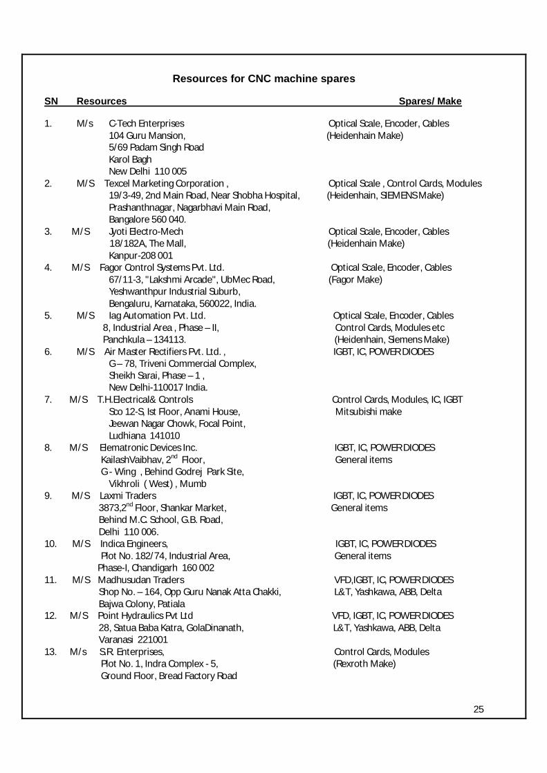
Resources for CNC machine spares
SN Resources Spares/ Make
1. M/s C-Tech Enterprises Optical Scale, Encoder, Cables 104 Guru Mansion, (Heidenhain Make) 5/69 Padam Singh Road Karol Bagh New Delhi 110 005 2. M/S Texcel Marketing Corporation , Optical Scale , Control Cards, Modules 19/3-49, 2nd Main Road, Near Shobha Hospital, (Heidenhain, SIEMENS Make) Prashanthnagar, Nagarbhavi Main Road, Bangalore 560 040. 3. M/S Jyoti Electro-Mech Optical Scale, Encoder, Cables 18/182A, The Mall, (Heidenhain Make) Kanpur-208 001 4. M/S Fagor Control Systems Pvt. Ltd. Optical Scale, Encoder, Cables 67/11-3, "Lakshmi Arcade", UbMec Road, (Fagor Make) Yeshwanthpur Industrial Suburb, Bengaluru, Karnataka, 560022, India. 5. M/S Iag Automation Pvt. Ltd. Optical Scale, Encoder, Cables 8, Industrial Area , Phase – II, Control Cards, Modules etc Panchkula – 134113. (Heidenhain, Siemens Make) 6. M/S Air Master Rectifiers Pvt. Ltd. , IGBT, IC, POWER DIODES G – 78, Triveni Commercial Complex, Sheikh Sarai, Phase – 1 , New Delhi-110017 India. 7. M/S T.H.Electrical& Controls Control Cards, Modules, IC, IGBT Sco 12-S, Ist Floor, Anami House, Mitsubishi make Jeewan Nagar Chowk, Focal Point, Ludhiana 141010 8. M/S Elematronic Devices Inc. IGBT, IC, POWER DIODES KailashVaibhav, 2nd Floor, General items G - Wing , Behind Godrej Park Site, Vikhroli ( West) , Mumb 9. M/S Laxmi Traders IGBT, IC, POWER DIODES 3873,2nd Floor, Shankar Market, General items Behind M.C. School, G.B. Road, Delhi 110 006. 10. M/S Indica Engineers, IGBT, IC, POWER DIODES Plot No. 182/74, Industrial Area, General items Phase-I, Chandigarh 160 002 11. M/S Madhusudan Traders VFD,IGBT, IC, POWER DIODES Shop No. – 164, Opp Guru Nanak Atta Chakki, L&T, Yashkawa, ABB, Delta Bajwa Colony, Patiala 12. M/S Point Hydraulics Pvt Ltd VFD, IGBT, IC, POWER DIODES 28, Satua Baba Katra, GolaDinanath, L&T, Yashkawa, ABB, Delta Varanasi 221001 13. M/s S.R. Enterprises, Control Cards, Modules Plot No. 1, Indra Complex - 5, (Rexroth Make) Ground Floor, Bread Factory Road

26
14. M/S Monika Engineers Power supplies, sensors, switches Rukmani tower, 77-a, Industrial Estate. General Items MillerganjLudhiana 141003. 15. M/S Namarta Trade Links, Power supplies, sensors, switches SCO – 40, Sector – 7C, General Items Madhya Marg, Chandigarh. 16. M/s Indotech Engineers Power supplies, sensors, switches #36, Under Dholewal Flyover. General Items DholewalChowk, Ludhiana 141003. 17. M/s Phoenix Contact India Pvt Ltd. Power supplies, sensors, switches F-26/2, Okhla Industrial Area, Phase – II, General Items New Delhi – 110020. 18. M/S Vishesh Enterprises, VFD,Power supplies, sensors, Plot No. 12/A, ChittaMandir Road, switches Village Gadhauli, Yamunanagar L&T, Yashkawa, ABB, Delta 19. M/s Fanuc India Pvt Limited Control cards, modules # 41A, Electronics City OEM Bangalore 560 100 20. M/S Pepperl + Fuchs(India) Pvt Ltd. Linear position sensors, switches
6th Floor, Block – Ii, Vatika Business Park, OEM Sohna Road, Sector – 49, Gurgaon – 122002
21. M/S GiviMisurePvt Ltd. Optical scales VITC Export Bhavan, Ist Block, OEM Plot No. 488, Kiadb Complex, 14th Cross, Iv Phase, Peenya Industrial Area, Banglore – 560 058. 22. M/S B.I. Enterprise, Switches, sensors, multiple limit switch B-210, Arjun Centre, OEM Govandi Station Road. Govandi (E) Mumbai 400 088 23. M/S Larson & Toubro Limited VFD’s , control cards Sco 32, Sector 26-D, OEM Madhya Marg, Chandigarh 160 019 24. M/S Rockwell Automation India Pvt. Ltd. VFD’s, control cards A-66, Sector – 64 For Allen Bredley Make Noida (U.P.) 20130. India 25. M/S Agromach Spares Corporation VFD’s, control cards 194/D, Gaiwadi Compound, Girgaum Road For Indramat& Rexroth make Mumbai - 400004, Maharashtra, India. 26. M/S Siemens Ltd OEM Plot 78, Sector 18, Jil Building, Tower - B, Gurgaon 122015


![[Special Series] Haas ST-10 Series Lathes - CNC … Maschinen/Haas ST-10.pdf · [Special Series] Haas ST-10 Series Lathes ... ISO standard G-code programming ... CNC control, or use](https://static.fdocuments.in/doc/165x107/5ad8e3b17f8b9a3e578def2a/special-series-haas-st-10-series-lathes-cnc-maschinenhaas-st-10pdfspecial.jpg)