
TROUBLESHOOTING - 16x1p531pcnxjpi9p2ewt95n … · TROUBLESHOOTING: Note: You will have a check...
16
Transcript of TROUBLESHOOTING - 16x1p531pcnxjpi9p2ewt95n … · TROUBLESHOOTING: Note: You will have a check...

2 Turbo Kit - 6.4L Power Stroke • www.hs-motorsports.com
TROUBLESHOOTING:Note: You will have a check engine light and/or other problems unless using this product with a compatible ECM calibration. H&S Motorsports provides compatible calibrations for H&S Performance tuning devices at www.hs-motorsports.com/calibrations. If you are not using an H&S Performance tuning device, it is YOUR responsibility to contact your tuning supplier to verify compatibility.
Please read and understand all installation instructions before proceeding with the installation
If you have any questions during the installation of this product, please email H&S Motorsports support at [email protected]
TABLE OF CONTENTSPARTS LIST .................................................................................................................PG. 2
INSTALLATION ............................................................................................................PG. 3
WARRANTY & DISCLAIMER ........................................................................................PG. 15
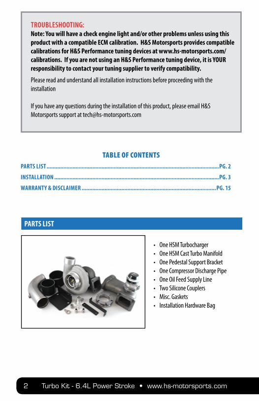
• One HSM Turbocharger• One HSM Cast Turbo Manifold• One Pedestal Support Bracket• One Compressor Discharge Pipe• One Oil Feed Supply Line• Two Silicone Couplers• Misc. Gaskets• Installation Hardware Bag
PARTS LIST

www.hs-motorsports.com • Turbo Kit - 6.4L Power Stroke 3
Disconnect the negative cable connection from both batteries. Locate the radiator drain on the lower driver side of the radiator and drain the cooling system. Remove the air intake system.
Remove the factory turbo oil feed line assembly. Remove the 4 heat shield bolts from the top of the fac-tory turbochargers and remove the heat shield.
INSTALLATION
STEP 1
STEP 2

4 Turbo Kit - 6.4L Power Stroke • www.hs-motorsports.com
Spray a light amount of penetrating oil on the downpipe v-band clamp, turbocharger pedestal bolts, upper up-pipe bolts.
Remove the v-band clamp from the factory downpipe.
Remove the positive battery cable from the driver’s side battery and remove the battery from the vehicle. Disconnect all coolant lines from the main coolant reservoir. Lift the coolant reservoir assembly up and disconnect the vacuum line from the bottom. Remove the coolant reservoir from the vehicle.
STEP 3
STEP 4
STEP 5
www.hs-motorsports.com • Turbo Kit - 6.4L Power Stroke 5
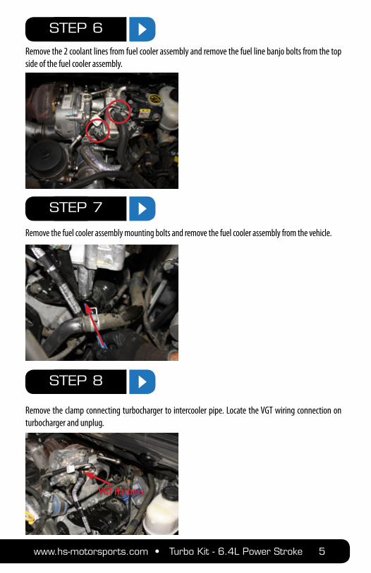
Remove the 2 coolant lines from fuel cooler assembly and remove the fuel line banjo bolts from the top side of the fuel cooler assembly.
Remove the fuel cooler assembly mounting bolts and remove the fuel cooler assembly from the vehicle.
Remove the clamp connecting turbocharger to intercooler pipe. Locate the VGT wiring connection on turbocharger and unplug.
STEP 6
STEP 7
STEP 8
VGT Harness
6 Turbo Kit - 6.4L Power Stroke • www.hs-motorsports.com
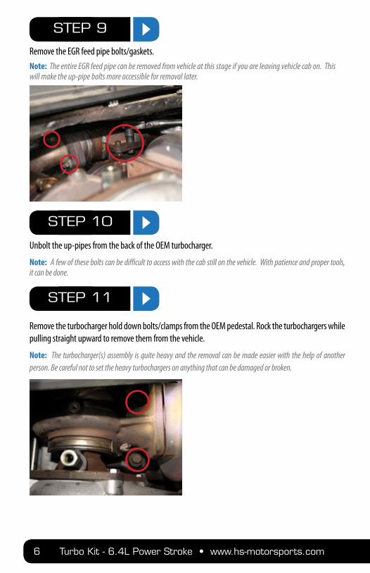
Remove the EGR feed pipe bolts/gaskets. Note: The entire EGR feed pipe can be removed from vehicle at this stage if you are leaving vehicle cab on. This will make the up-pipe bolts more accessible for removal later.
Unbolt the up-pipes from the back of the OEM turbocharger.
Note: A few of these bolts can be difficult to access with the cab still on the vehicle. With patience and proper tools, it can be done.
Remove the turbocharger hold down bolts/clamps from the OEM pedestal. Rock the turbochargers while pulling straight upward to remove them from the vehicle.
Note: The turbocharger(s) assembly is quite heavy and the removal can be made easier with the help of another person. Be careful not to set the heavy turbochargers on anything that can be damaged or broken.
STEP 9
STEP 10
STEP 11
www.hs-motorsports.com • Turbo Kit - 6.4L Power Stroke 7
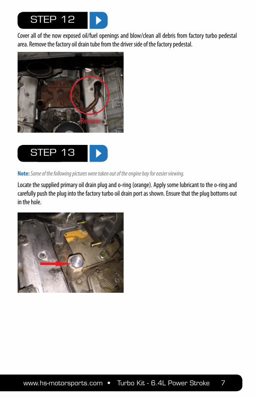
Cover all of the now exposed oil/fuel openings and blow/clean all debris from factory turbo pedestal area. Remove the factory oil drain tube from the driver side of the factory pedestal.
Note: Some of the following pictures were taken out of the engine bay for easier viewing.
Locate the supplied primary oil drain plug and o-ring (orange). Apply some lubricant to the o-ring and carefully push the plug into the factory turbo oil drain port as shown. Ensure that the plug bottoms out in the hole.
STEP 12
STEP 13
Remove
8 Turbo Kit - 6.4L Power Stroke • www.hs-motorsports.com
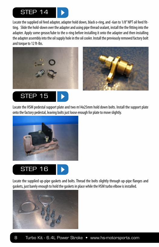
Locate the supplied oil feed adapter, adapter hold down, black o-ring, and -6an to 1/8” NPT oil feed fit-ting. Slide the hold-down over the adapter and using pipe thread sealant, install the the fitting into the adapter. Apply some grease/lube to the o-ring before installing it onto the adapter and then installing the adapter assembly into the oil supply hole in the oil cooler. Install the previously removed factory bolt and torque to 12 ft-lbs.
Locate the HSM pedestal support plate and two m14x25mm hold down bolts. Install the support plate onto the factory pedestal, leaving bolts just loose enough for plate to move slightly.
Locate the supplied up-pipe gaskets and bolts. Thread the bolts slightly through up-pipe flanges and gaskets, just barely enough to hold the gaskets in place while the HSM turbo elbow is installed.
STEP 14
STEP 15
STEP 16
www.hs-motorsports.com • Turbo Kit - 6.4L Power Stroke 9
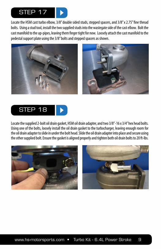
Locate the HSM cast turbo elbow, 3/8” double sided studs, stepped spacers, and 3/8” x 2.75” fine thread bolts. Using a stud tool, install the two supplied studs into the wastegate side of the cast elbow. Bolt the cast manifold to the up-pipes, leaving them finger tight for now. Loosely attach the cast manifold to the pedestal support plate using the 3/8” bolts and stepped spacers as shown.
Locate the supplied 2-bolt oil drain gasket, HSM oil drain adapter, and two 3/8”-16 x 3/4” hex head bolts. Using one of the bolts, loosely install the oil drain gasket to the turbocharger, leaving enough room for the oil drain adapter to slide in under the bolt head. Slide the oil drain adapter into place and secure using the other supplied bolt. Ensure the gasket is aligned properly and tighten both oil drain bolts to 20 ft-lbs.
STEP 17
STEP 18
10 Turbo Kit - 6.4L Power Stroke • www.hs-motorsports.com
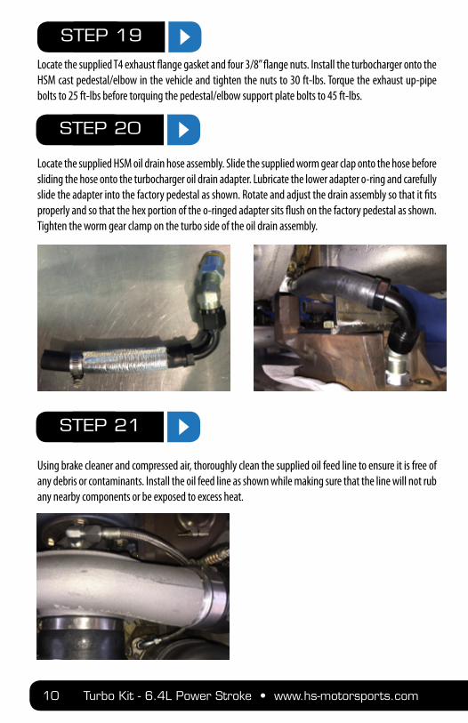
Locate the supplied T4 exhaust flange gasket and four 3/8” flange nuts. Install the turbocharger onto the HSM cast pedestal/elbow in the vehicle and tighten the nuts to 30 ft-lbs. Torque the exhaust up-pipe bolts to 25 ft-lbs before torquing the pedestal/elbow support plate bolts to 45 ft-lbs.
Locate the supplied HSM oil drain hose assembly. Slide the supplied worm gear clap onto the hose before sliding the hose onto the turbocharger oil drain adapter. Lubricate the lower adapter o-ring and carefully slide the adapter into the factory pedestal as shown. Rotate and adjust the drain assembly so that it fits properly and so that the hex portion of the o-ringed adapter sits flush on the factory pedestal as shown. Tighten the worm gear clamp on the turbo side of the oil drain assembly.
Using brake cleaner and compressed air, thoroughly clean the supplied oil feed line to ensure it is free of any debris or contaminants. Install the oil feed line as shown while making sure that the line will not rub any nearby components or be exposed to excess heat.
STEP 19
STEP 20
STEP 21

www.hs-motorsports.com • Turbo Kit - 6.4L Power Stroke 11
If you will not be using an external wastegate, block the wastegate port on the cast elbow using the supplied plug and clamp.
Re-install the EGR feed pipe that was unbolted/removed in step 9. Re-use the factory gaskets/hardware and torque to 20 lb*ft.
Locate the factory fuel cooler assembly that was removed in step 7. Remove the cooler from the alumi-num boost supply tube that was on the factory turbocharger system. Locate the supplied HSM fuel cooler mounting brackets and 5/16”x1” bolts/washers/nuts. Install the fuel cooler assembly with brackets and hardware as shown. Re-install the fuel banjo bolts with supplied sealing washers and re-install the cool-ant lines onto the fuel cooler assembly.
STEP 22
STEP 23
STEP 24

12 Turbo Kit - 6.4L Power Stroke • www.hs-motorsports.com
If performing this installation with the cab ON the vehicle, the factory downpipe will need be cut with a sawzall to allow removal. Cut the downpipe just before the indentation as shown. Remove the bolts from the lower exhaust ball-flange connection and remove the factory down-pipe from the vehicle.
Note: If performing this installation with the cab OFF the vehicle, simply unbolt and remove the factory down-pipe.
Install the supplied upper down-pipe section to the turbocharger using the factory down-pipe clamp. Tighten the clamp just enough that the down-pipe is centered on the turbocharger outlet but can still be moved slightly for final adjustments. Slide the supplied 4” exhaust band clamp onto the supplied lower down-pipe section before sliding the lower down-pipe onto the upper down-pipe. Align the lower ball flange and loosely install the supplied bolts/nuts at the lower connection. Adjust the down-pipe assem-bly so that it is not coming in contact with the fuel line, firewall, transmission, or any other components. After the proper clearance has been achieved, tighten the clamp on the turbocharger, then the ball-flange connection hardware, then the flat band clamp while making sure that the downpipe maintains the correct orientation and does not come in contact with any other components.
STEP 25
STEP 26

www.hs-motorsports.com • Turbo Kit - 6.4L Power Stroke 13
Locate the supplied compressor discharge pipe, 2.5” x 3” adapter coupling, 1/8” pipe plug, and 2 t-bolt clamps. Install the supplied 1/8” pipe plug into the supplied discharge pipe with thread sealant if you do not need a boost reference for a wastegate or other accessories. Install the 2.5” x 3” adapter coupling onto the discharge pipe between the turbocharger outlet and the intercooler piping. Ensure that all in-tercooler piping is adjusted properly and is not rubbing on anything before tigthening the t-bolt clamps.
Re-install factory coolant reservoir/battery tray assembly into the vehicle making sure the vacuum res-ervoir line is plugged in on the bottom of the assembly. Re-install all cooling lines, locking clips and bolts and re-install the driver side battery. Re-fill the cooling system with approved coolant.
Note: Old coolant may be re-used if it is new and clean, this is a decision of the installer.
If you have an OEM intake system, you may need to trim it back and use provided 4” boot and clamps. If you have an aftermarket intake system, some adjustments may be necessary to fit it to the turbocharger. Make any adjustments necessary and install your intake system.
STEP 28
STEP 29
STEP 27

14 Turbo Kit - 6.4L Power Stroke • www.hs-motorsports.com
Re-install battery cables. Go over vehicle and make sure every step was completed and you have tight-ened all hardware to specification.
Start engine and check for leaks. Test drive vehicle and check for leaks.
Enjoy the finest 6.4L turbo system on the planet, and have a nice day.
STEP 32
STEP 31
STEP 30

www.hs-motorsports.com • Turbo Kit - 6.4L Power Stroke 15
WARRANTY & DISCLAIMER All HSM Turbo Systems are considered high performance racing parts, and are intended and developed for non-street-legal, off-highway, closed course racing use ONLY!
Installation of this product on a non-sanctioned race vehicle, on ANY road, public or private, is STRICTLY PROHIBITED in the United States and Canada. This product may cause the vehicle it is installed on to exceed federal emissions limits, and therefore cannot be installed on any vehicle that has been certified or registered for highway use. Removing your emissions equipment, including but not limited to, exhaust gas recirculation(EGR), catalytic converter, or Diesel Particulate Filter(DPF), is against federal regulations set forth by the EPA, when not used for closed-course sanctioned racing. H & S Motorsports, LLC strongly recommends that all emis-sions equipment be left in place at all times on any vehicle that has been registered or certified for highway use. By purchasing or installing this high performance product, you release H & S Motorsports, LLC of any and all liabilities, and assume all responsibility for making sure your vehicle is compliant with all local, state, and federal emissions regulations. By installing this product you agree to these terms and conditions, and also acknowledge that installing a high performance product on your vehicle may void your manufactures warranty. By installing this product, you assume all risks and liabilities, including but not limited to, loss of vehicle warranty, fines, and/or civil penalties. By installing this product, you assume all associated risks and liabilities, and in no way will hold H & S Motorsports, LLC liable for any unlawful use, misuse, or consequential damages.


![· nbr nbr stl tnm ecm ecm fcm fcm ecm fcm ecm ecm ecm stl stl rip nbr nbr ny nbr cm szz szz stip nbr cc cc nbr fpm sng s description screw, i-ih 14) [3103]](https://static.fdocuments.in/doc/165x107/5be3e29109d3f25b628c4d3a/-nbr-nbr-stl-tnm-ecm-ecm-fcm-fcm-ecm-fcm-ecm-ecm-ecm-stl-stl-rip-nbr-nbr-ny-nbr.jpg)