TROUBLE CODE 11 4 - UK Buell Enthusiasts Group Buell X1/sm04c.pdf2001 Buell X1: Fuel System 4-45...
43
2001 Buell X1: Fuel System 4-45 HOME TROUBLE CODE 11 4.17 GENERAL Throttle Position Sensor See Figure 4-40. The throttle position sensor (TP sensor) is supplied 5.0 volts from the ECM (5v REF) and sends a signal back to the ECM (TP sensor signal) which varies according to throttle position. The output signal from the TP sensor varies from: ● 0.5-1.5 volts at idle (closed throttle). ● 3.9-4.9 volts at wide open throttle. A Code 11 will set if the TP sensor signal voltage does not fall within the acceptable range. NOTE If the TP sensor is removed and/or replaced, the sensor must be calibrated using a Scanalyzer. See 4.36 THROTTLE POSITION SENSOR. DIAGNOSTICS DiagnosticTips The Scanalyzer reads throttle position in degrees. TP sensor voltage should increase at a steady rate as throttle is moved from idle to wide open throttle. An open or short to ground in R/W or BK/W wires will also result in a Code 11. Check for the following conditions: ● Poor connection. Inspect ECM harness connector for backed out terminals, improper mating, broken locks improperly formed or damaged terminals, poor terminal- to-wire connection and damaged harness. ● Perform 4.8 WIGGLE TEST to locate intermittents. If connections and harness check out OK, monitor TP sen- sor voltage using a Scanalyzer or DVOM while moving related connectors and wiring harness. If the failure is induced, the TP sensor display will change. ● TP sensor scaling. Observe the TP sensor voltage dis- play while opening the throttle with engine stopped and ignition switch ON. Display should vary from closed throttle TP sensor voltage (when throttle is closed) to greater than 4.0 volts (when throttle is held wide open). As the throttle is slowly moved, the voltage should change gradually without spikes or low voltages being observed. Scanalyzer Notes The Scanalyzer icon appears at those points in the flow chart where the Scanalyzer can be used. Diagnostic Notes The reference numbers below correlate with the circled num- bers on the Code 11 flow charts. 1. Connect BREAKOUT BOX (Part No. HD-42682) to ECM. See 4.7 BREAKOUT BOX. 2. Use HARNESS CONNECTOR TEST KIT (Part No. HD- 41404), black socket probe and patch cord. Figure 4-40. TP Sensor Assembly Figure 4-41. TP Sensor Terminals [88A] 2 6764 1 3 1. Throttle Position Sensor and Harness 2. Screws (2) (metric) 3. Throttle Shaft b0651x4x A (R/W Wire) B (V/Y Wire) C (BK/W Wire)
Transcript of TROUBLE CODE 11 4 - UK Buell Enthusiasts Group Buell X1/sm04c.pdf2001 Buell X1: Fuel System 4-45...
HOME
TROUBLE CODE 11 4.17
GENERAL
Throttle Position Sensor
See Figure 4-40. The throttle position sensor (TP sensor) issupplied 5.0 volts from the ECM (5v REF) and sends a signalback to the ECM (TP sensor signal) which varies according tothrottle position. The output signal from the TP sensor variesfrom:
● 0.5-1.5 volts at idle (closed throttle).
● 3.9-4.9 volts at wide open throttle.
A Code 11 will set if the TP sensor signal voltage does not fallwithin the acceptable range.
NOTEIf the TP sensor is removed and/or replaced, the sensor mustbe calibrated using a Scanalyzer. See 4.36 THROTTLEPOSITION SENSOR.
DIAGNOSTICS
DiagnosticTips
The Scanalyzer reads throttle position in degrees. TP sensorvoltage should increase at a steady rate as throttle is movedfrom idle to wide open throttle. An open or short to ground inR/W or BK/W wires will also result in a Code 11.
Check for the following conditions:
● Poor connection. Inspect ECM harness connector forbacked out terminals, improper mating, broken locksimproperly formed or damaged terminals, poor terminal-to-wire connection and damaged harness.
● Perform 4.8 WIGGLE TEST to locate intermittents. Ifconnections and harness check out OK, monitor TP sen-sor voltage using a Scanalyzer or DVOM while movingrelated connectors and wiring harness. If the failure isinduced, the TP sensor display will change.
● TP sensor scaling. Observe the TP sensor voltage dis-play while opening the throttle with engine stopped andignition switch ON. Display should vary from closedthrottle TP sensor voltage (when throttle is closed) togreater than 4.0 volts (when throttle is held wide open).As the throttle is slowly moved, the voltage shouldchange gradually without spikes or low voltages beingobserved.
Scanalyzer Notes
The Scanalyzer icon appears at those points in the flow chartwhere the Scanalyzer can be used.
Diagnostic NotesThe reference numbers below correlate with the circled num-bers on the Code 11 flow charts.
1. Connect BREAKOUT BOX (Part No. HD-42682) to ECM.See 4.7 BREAKOUT BOX.
2. Use HARNESS CONNECTOR TEST KIT (Part No. HD-41404), black socket probe and patch cord.
Figure 4-40. TP Sensor Assembly
Figure 4-41. TP Sensor Terminals [88A]
2
6764
1
3
1. Throttle Position Sensor and Harness2. Screws (2) (metric)3. Throttle Shaft
b0651x4x
A (R/W Wire)
B (V/Y Wire)
C (BK/W Wire)
2001 Buell X1: Fuel System 4-45
HOME
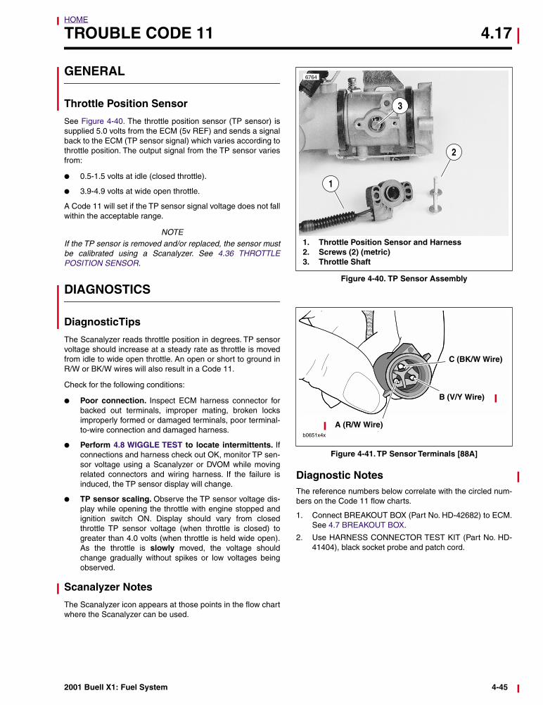
Figure 4-42. Throttle Position Sensor Circuit
CBA
b0526x4x
Throttle Position Sensor
[88]
R/W V/Y
BK
/W
b0527x4x
R/W BK/W
GN/W
Electronic Control Module(ECM)
Connector [10] Connector [11]
Cam PositionSensor
R/W = 5 Volt ReferenceV/Y = TP Sensor SignalBK/W = Sensor Ground
R/W V/Y
GN
/W
BK
/W
A B C[14]
BK/WR/W
GN/W
Table 4-14. Wire Harness Connectors in Figure 4-42.
NO. DESCRIPTION TYPE LOCATION
[11] ECM (gray) 12-place Deutsch under seat
[14] Cam position sensor 3-place Deutsch near starter
[88] TP sensor 3-place Packard behind air cleaner backplate
4-46 2001 Buell X1: Fuel System
HOME
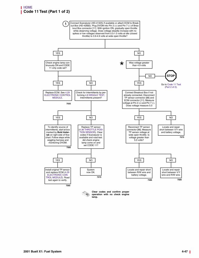
Code 11 Test (Part 1 of 2)
Connect Scanalyzer (HD-41325) if available or attach ECM to Break-out Box (HD-42682). Plug DVOM into Pin 2 (+) and Pin 7 (-) of Brea-
kout Box connector [11]. With ignition ON, gradually open throttle while observing voltage. Does voltage steadily increase with no
spikes or low voltages observed from 0.5-1.5 volts at idle (closed throttle) to 3.9-4.9 volts at wide open throttle?
Was voltage greater than 4.9 volts
NOYES
Check engine lamp con-tinuously ON and CODE
11 only code set?
YES
Replace ECM. See 4.29 ELECTRONIC CONTROL
MODULE.
NO
Check for intermittents by per-forming 4.8 WIGGLE TEST.
Intermittents present?
YES
To identify source of intermittents, start at box marked by Bold Aster-isk on right side of flow
chart. Follow steps while wiggling harness and
monitoring DVOM.
NO
Replace TP sensor (4.36 THROTTLE POSI-TION SENSOR). Clear codes if Scanalyzer is
available and road test. did check engine
lamp come on and set CODE 11?
NO
System now OK.
YES
Install original TP sensor and replace ECM (4.29 ELECTRONIC CON-
TROL MODULE). Road test again to verify.
*YES
Connect Breakout Box if not already connected. Disconnect TP sensor connector [88] and ECM connector [11]. Measure
voltage at Pin 2 (+) and Pin 7 (-). Does voltage measure 5.0
NO
Go to Code 11 Test (Part 2 of 2).
STOP
YES
Reconnect TP sensor connector [88]. Measure
TP sensor voltage at wide open throttle. Is voltage greater than
5.0 volts?
YES
Locate and repair short between R/W wire and
battery voltage.
7555
7560
7565
7570
1
NO
Locate and repair short between V/Y wire
and battery voltage.
NO
Locate and repair short between V/Y wire and R/W wire.
7586 7585
7575
Clear codes and confirm properoperation with no check enginelamp.
2001 Buell X1: Fuel System 4-47
HOME
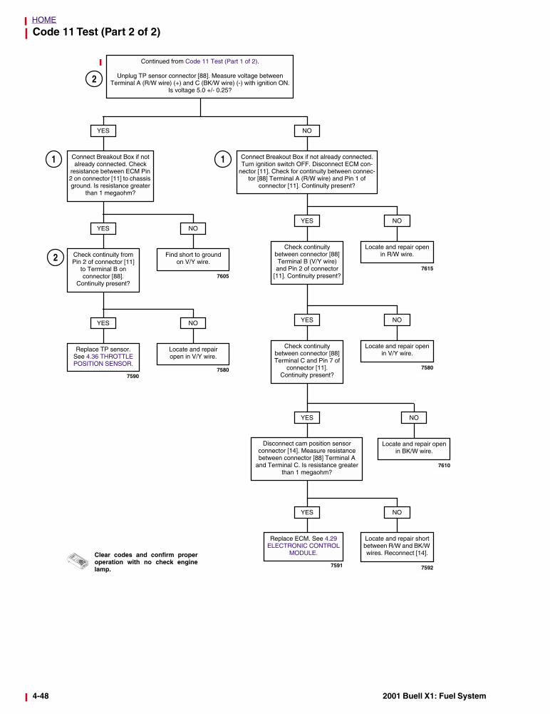
Code 11 Test (Part 2 of 2)
Clear codes and confirm properoperation with no check enginelamp.
Connect Breakout Box if not already connected. Turn ignition switch OFF. Disconnect ECM con-
nector [11]. Check for continuity between connec-tor [88] Terminal A (R/W wire) and Pin 1 of
connector [11]. Continuity present?
NO
Continued from Code 11 Test (Part 1 of 2).
Unplug TP sensor connector [88]. Measure voltage between Terminal A (R/W wire) (+) and C (BK/W wire) (-) with ignition ON.
Is voltage 5.0 +/- 0.25?
YES
Connect Breakout Box if not already connected. Check
resistance between ECM Pin 2 on connector [11] to chassis ground. Is resistance greater
than 1 megaohm?
Find short to groundon V/Y wire.
NO
Check continuity from Pin 2 of connector [11]
to Terminal B on connector [88].
Continuity present?
YES
Locate and repair open in V/Y wire.
NO
Replace TP sensor. See 4.36 THROTTLE POSITION SENSOR.
YES
75907580
7605
Locate and repair open in R/W wire.
NO
Check continuity between connector [88] Terminal B (V/Y wire) and Pin 2 of connector
[11]. Continuity present?
YES
7615
Locate and repair open in V/Y wire.
NO
Check continuity between connector [88] Terminal C and Pin 7 of
connector [11]. Continuity present?
YES
7580
Locate and repair open in BK/W wire.
NO
Disconnect cam position sensor connector [14]. Measure resistance between connector [88] Terminal A
and Terminal C. Is resistance greater than 1 megaohm?
YES
7610
Locate and repair short between R/W and BK/W wires. Reconnect [14].
NO
Replace ECM. See 4.29 ELECTRONIC CONTROL
MODULE.
YES
7592
2
1 1
2
7591
4-48 2001 Buell X1: Fuel System
HOME
TROUBLE CODE 13 4.18
GENERAL
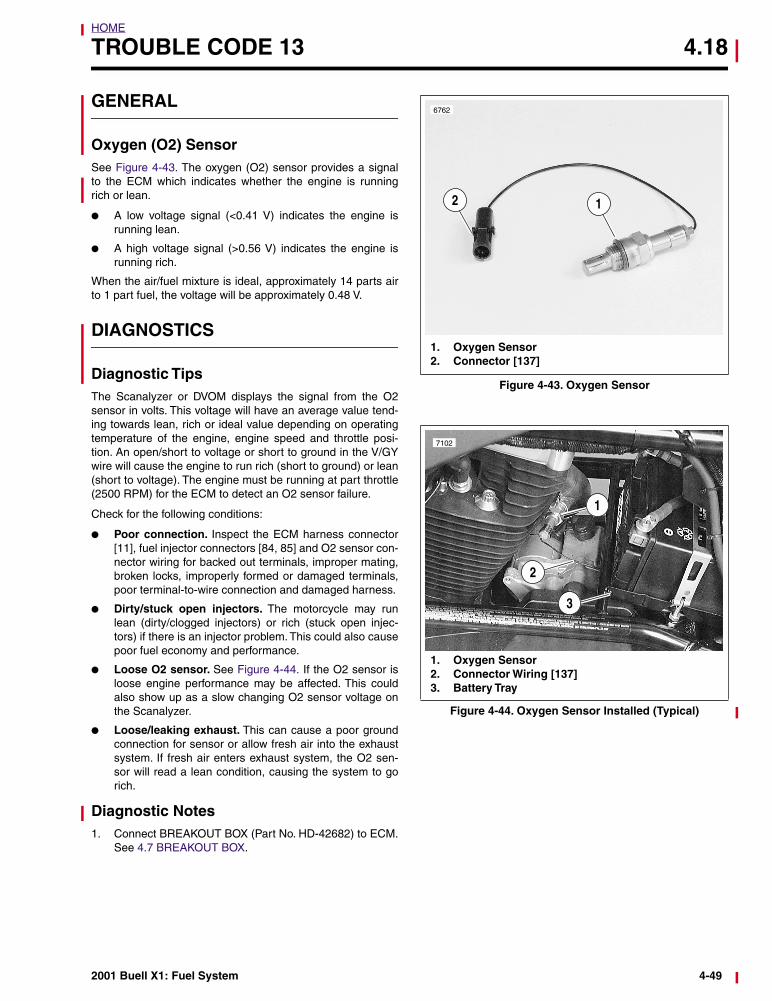
Oxygen (O2) Sensor See Figure 4-43. The oxygen (O2) sensor provides a signalto the ECM which indicates whether the engine is runningrich or lean.
● A low voltage signal (<0.41 V) indicates the engine isrunning lean.
● A high voltage signal (>0.56 V) indicates the engine isrunning rich.
When the air/fuel mixture is ideal, approximately 14 parts airto 1 part fuel, the voltage will be approximately 0.48 V.
DIAGNOSTICS
Diagnostic TipsThe Scanalyzer or DVOM displays the signal from the O2sensor in volts. This voltage will have an average value tend-ing towards lean, rich or ideal value depending on operatingtemperature of the engine, engine speed and throttle posi-tion. An open/short to voltage or short to ground in the V/GYwire will cause the engine to run rich (short to ground) or lean(short to voltage). The engine must be running at part throttle(2500 RPM) for the ECM to detect an O2 sensor failure.
Check for the following conditions:
● Poor connection. Inspect the ECM harness connector[11], fuel injector connectors [84, 85] and O2 sensor con-nector wiring for backed out terminals, improper mating,broken locks, improperly formed or damaged terminals,poor terminal-to-wire connection and damaged harness.
● Dirty/stuck open injectors. The motorcycle may runlean (dirty/clogged injectors) or rich (stuck open injec-tors) if there is an injector problem. This could also causepoor fuel economy and performance.
● Loose O2 sensor. See Figure 4-44. If the O2 sensor isloose engine performance may be affected. This couldalso show up as a slow changing O2 sensor voltage onthe Scanalyzer.
● Loose/leaking exhaust. This can cause a poor groundconnection for sensor or allow fresh air into the exhaustsystem. If fresh air enters exhaust system, the O2 sen-sor will read a lean condition, causing the system to gorich.
Diagnostic Notes1. Connect BREAKOUT BOX (Part No. HD-42682) to ECM.
See 4.7 BREAKOUT BOX.
Figure 4-43. Oxygen Sensor
Figure 4-44. Oxygen Sensor Installed (Typical)
2
6762
1. Oxygen Sensor2. Connector [137]
1
1
7102
2
3
1. Oxygen Sensor2. Connector Wiring [137]3. Battery Tray
2001 Buell X1: Fuel System 4-49
HOME
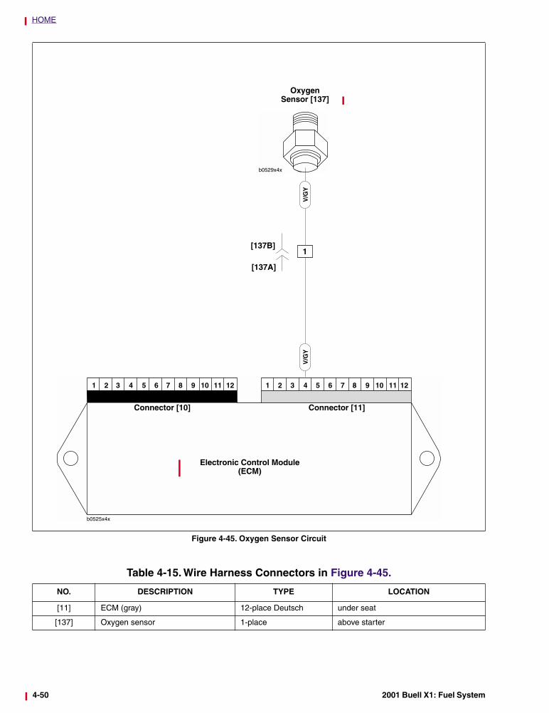
Figure 4-45. Oxygen Sensor Circuit
b0529x4x
OxygenSensor [137]
Electronic Control Module(ECM)
Connector [10] Connector [11]
V/G
YV
/GY
1[137B]
[137A]
Table 4-15. Wire Harness Connectors in Figure 4-45.
NO. DESCRIPTION TYPE LOCATION
[11] ECM (gray) 12-place Deutsch under seat
[137] Oxygen sensor 1-place above starter
4-50 2001 Buell X1: Fuel System
HOME
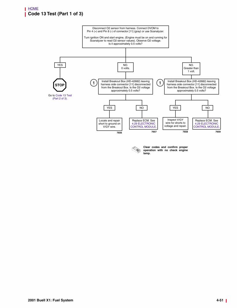
Code 13 Test (Part 1 of 3)
Install Breakout Box (HD-42682) leaving harness side connector [11] disconnected from the Breakout Box. Is the O2 voltage
approximately 0.5 volts?
NO. 0 volts.
NO.Greater than
1 volt.
YES
YES NO
Locate and repair short to ground on
V/GY wire.
Replace ECM. See 4.29 ELECTRONIC
CONTROL MODULE.
Disconnect O2 sensor from harness. Connect DVOM to Pin 4 (+) and Pin 8 (-) of connector [11] (gray) or use Scanalyzer.
Turn ignition ON and start engine. (Engine must be on and running for Scanalyzer to read O2 sensor values). Observe O2 voltage.
Is it approximately 0.5 volts?
Install Breakout Box (HD-42682) leaving harness side connector [11] disconnected from the Breakout Box. Is the O2 voltage
approximately 0.5 volts?
YES NO
Inspect V/GYwire for shorts to
voltage and repair.
Replace ECM. See 4.29 ELECTRONIC
CONTROL MODULE.
Go to Code 13 Test (Part 2 of 3).
STOP
7656 76597658
11
Clear codes and confirm properoperation with no check enginelamp.
7657
2001 Buell X1: Fuel System 4-51
HOME
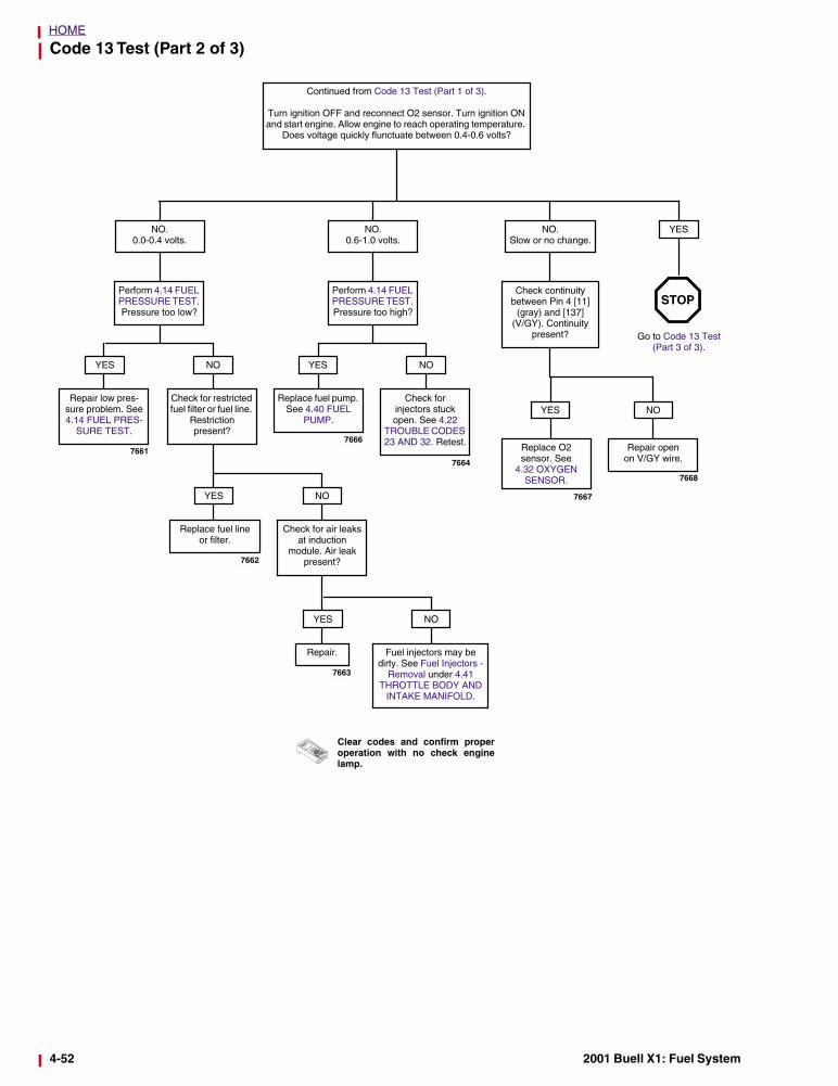
Code 13 Test (Part 2 of 3)
NO. 0.0-0.4 volts.
NO. 0.6-1.0 volts.
NO. Slow or no change.
Check continuity between Pin 4 [11]
(gray) and [137] (V/GY). Continuity
present?
Replace O2 sensor. See
4.32 OXYGEN SENSOR.
YES
Repair open on V/GY wire.
NO
Perform 4.14 FUEL PRESSURE TEST. Pressure too high?
NO
Perform 4.14 FUEL PRESSURE TEST. Pressure too low?
YES
Check for injectors stuck open. See 4.22
TROUBLE CODES 23 AND 32. Retest.
Continued from Code 13 Test (Part 1 of 3).
Turn ignition OFF and reconnect O2 sensor. Turn ignition ON and start engine. Allow engine to reach operating temperature.
Does voltage quickly flunctuate between 0.4-0.6 volts?
NOYES
Check for restricted fuel filter or fuel line.
Restriction present?
NO
Check for air leaks at induction
module. Air leak present?
YES
Replace fuel lineor filter.
NO
Fuel injectors may be dirty. See Fuel Injectors -
Removal under 4.41 THROTTLE BODY AND
INTAKE MANIFOLD.
YES
Repair.
Go to Code 13 Test (Part 3 of 3).
STOP
YES
Repair low pres-sure problem. See 4.14 FUEL PRES-
SURE TEST.
Replace fuel pump. See 4.40 FUEL
PUMP.
76617664
7666
7663
7667
7668
7662
Clear codes and confirm properoperation with no check enginelamp.
4-52 2001 Buell X1: Fuel System
HOME
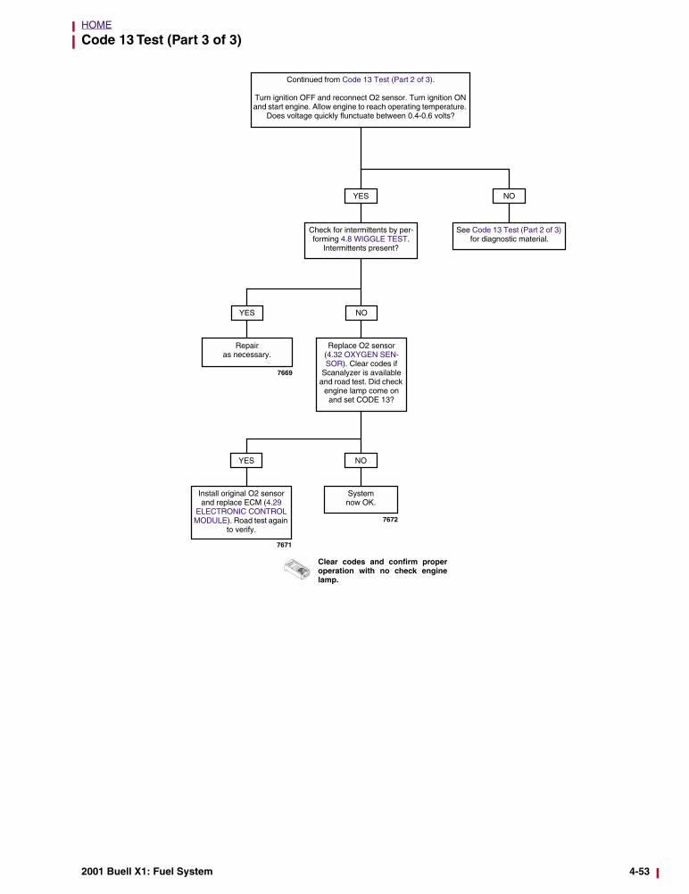
Code 13 Test (Part 3 of 3)
Check for intermittents by per-forming 4.8 WIGGLE TEST.
Intermittents present?
YES
Repair as necessary.
NO
Replace O2 sensor (4.32 OXYGEN SEN-SOR). Clear codes if
Scanalyzer is available and road test. Did check
engine lamp come on and set CODE 13?
NO
System now OK.
YES
Install original O2 sensor and replace ECM (4.29
ELECTRONIC CONTROL MODULE). Road test again
to verify.
YES
See Code 13 Test (Part 2 of 3) for diagnostic material.
NO
Continued from Code 13 Test (Part 2 of 3).
Turn ignition OFF and reconnect O2 sensor. Turn ignition ON and start engine. Allow engine to reach operating temperature.
Does voltage quickly flunctuate between 0.4-0.6 volts?
7669
7672
7671
Clear codes and confirm properoperation with no check enginelamp.
2001 Buell X1: Fuel System 4-53
HOME
TROUBLE CODE 14 4.19
GENERAL
Engine Temperature Sensor
CAUTION
Do not pull on engine temperature sensor wiring. Excessstrain to sensor wiring will cause sensor damage.
The ECM supplies and monitors a 0-5 volt signal to one sideof the engine temperature sensor (ET sensor). The other sideof the ET sensor is connected to ground through the engine.
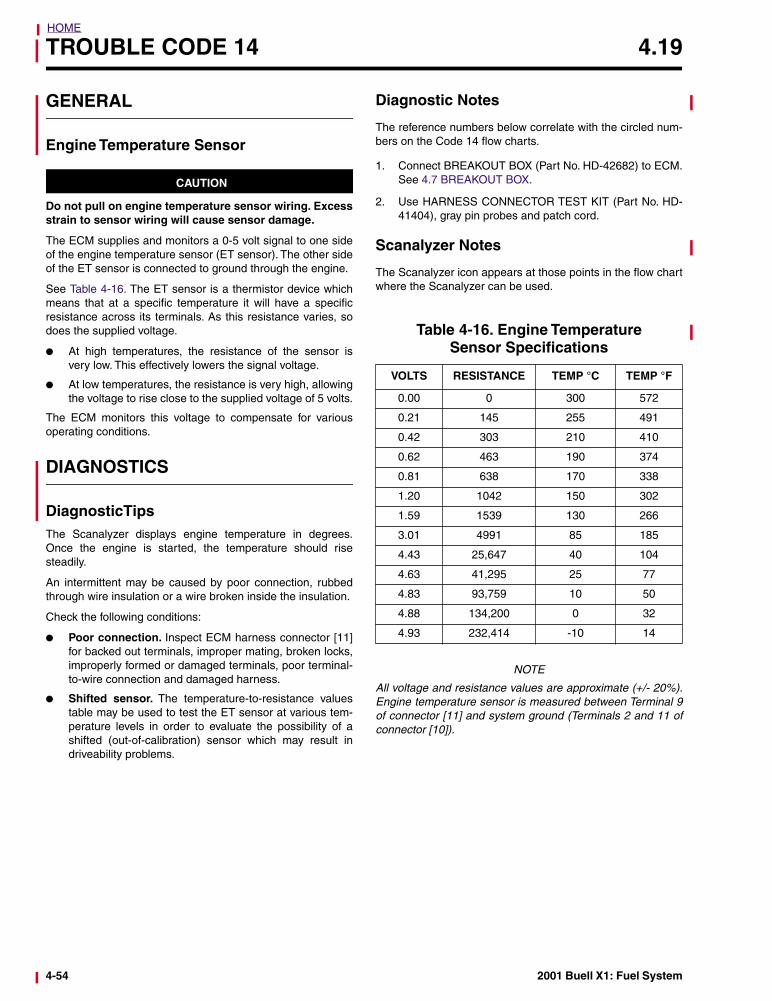
See Table 4-16. The ET sensor is a thermistor device whichmeans that at a specific temperature it will have a specificresistance across its terminals. As this resistance varies, sodoes the supplied voltage.
● At high temperatures, the resistance of the sensor isvery low. This effectively lowers the signal voltage.
● At low temperatures, the resistance is very high, allowingthe voltage to rise close to the supplied voltage of 5 volts.
The ECM monitors this voltage to compensate for variousoperating conditions.
DIAGNOSTICS
DiagnosticTipsThe Scanalyzer displays engine temperature in degrees.Once the engine is started, the temperature should risesteadily.
An intermittent may be caused by poor connection, rubbedthrough wire insulation or a wire broken inside the insulation.
Check the following conditions:
● Poor connection. Inspect ECM harness connector [11]for backed out terminals, improper mating, broken locks,improperly formed or damaged terminals, poor terminal-to-wire connection and damaged harness.
● Shifted sensor. The temperature-to-resistance valuestable may be used to test the ET sensor at various tem-perature levels in order to evaluate the possibility of ashifted (out-of-calibration) sensor which may result indriveability problems.
Diagnostic Notes
The reference numbers below correlate with the circled num-bers on the Code 14 flow charts.
1. Connect BREAKOUT BOX (Part No. HD-42682) to ECM.See 4.7 BREAKOUT BOX.
2. Use HARNESS CONNECTOR TEST KIT (Part No. HD-41404), gray pin probes and patch cord.
Scanalyzer Notes
The Scanalyzer icon appears at those points in the flow chartwhere the Scanalyzer can be used.
NOTE
All voltage and resistance values are approximate (+/- 20%).Engine temperature sensor is measured between Terminal 9of connector [11] and system ground (Terminals 2 and 11 ofconnector [10]).
Table 4-16. Engine TemperatureSensor Specifications
VOLTS RESISTANCE TEMP °C TEMP °F
0.00 0 300 572
0.21 145 255 491
0.42 303 210 410
0.62 463 190 374
0.81 638 170 338
1.20 1042 150 302
1.59 1539 130 266
3.01 4991 85 185
4.43 25,647 40 104
4.63 41,295 25 77
4.83 93,759 10 50
4.88 134,200 0 32
4.93 232,414 -10 14
4-54 2001 Buell X1: Fuel System
HOME
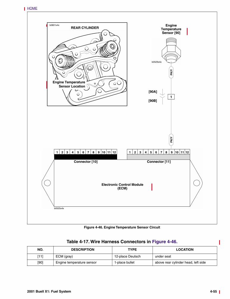
Figure 4-46. Engine Temperature Sensor Circuit
b0529x4x
EngineTemperature Sensor [90]
PK
/Y
Electronic Control Module(ECM)
Connector [10] Connector [11]
PK
/Y
1
Engine TemperatureSensor Location
b0801x4x
[90A]
[90B]
REAR CYLINDER
Table 4-17. Wire Harness Connectors in Figure 4-46.
NO. DESCRIPTION TYPE LOCATION
[11] ECM (gray) 12-place Deutsch under seat
[90] Engine temperature sensor 1-place bullet above rear cylinder head, left side
2001 Buell X1: Fuel System 4-55
HOME
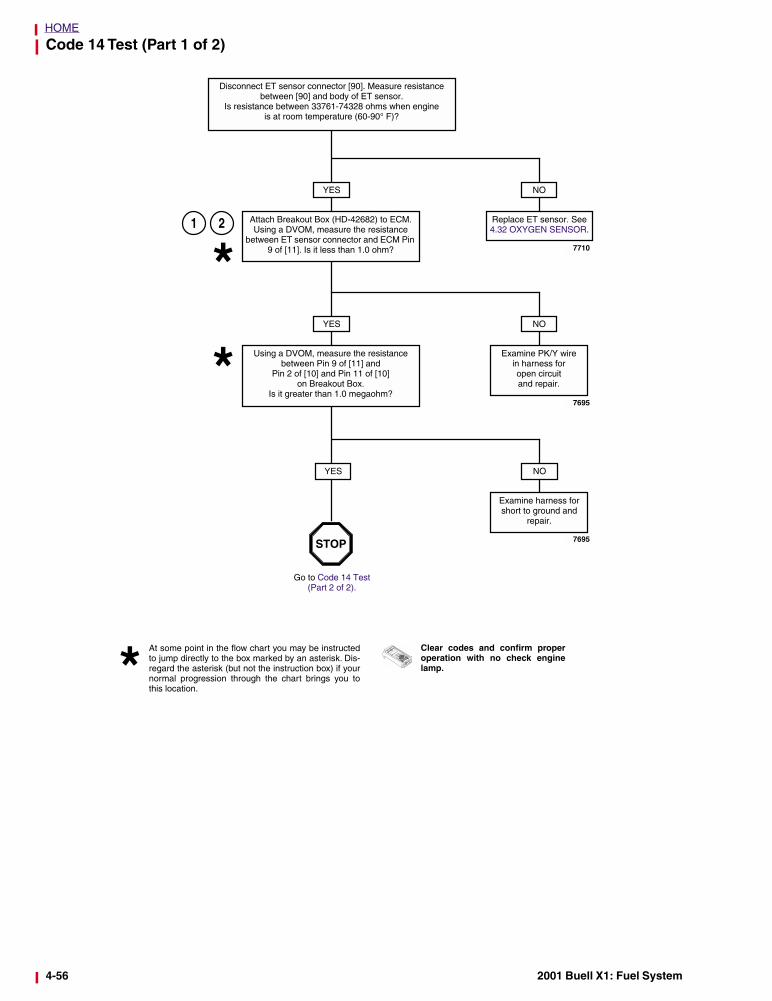
Code 14 Test (Part 1 of 2)
YES
2
Disconnect ET sensor connector [90]. Measure resistance between [90] and body of ET sensor.
Is resistance between 33761-74328 ohms when engineis at room temperature (60-90° F)?
Attach Breakout Box (HD-42682) to ECM. Using a DVOM, measure the resistance
between ET sensor connector and ECM Pin 9 of [11]. Is it less than 1.0 ohm?
NO
Replace ET sensor. See 4.32 OXYGEN SENSOR.
YES
Using a DVOM, measure the resistance between Pin 9 of [11] and
Pin 2 of [10] and Pin 11 of [10] on Breakout Box.
Is it greater than 1.0 megaohm?
NO
Examine PK/Y wire in harness for open circuit and repair.
YES NO
Examine harness for short to ground and
repair.
Clear codes and confirm properoperation with no check enginelamp.
At some point in the flow chart you may be instructedto jump directly to the box marked by an asterisk. Dis-regard the asterisk (but not the instruction box) if yournormal progression through the chart brings you tothis location.
Go to Code 14 Test (Part 2 of 2).
STOP
7710
7695
7695
1
4-56 2001 Buell X1: Fuel System
HOME
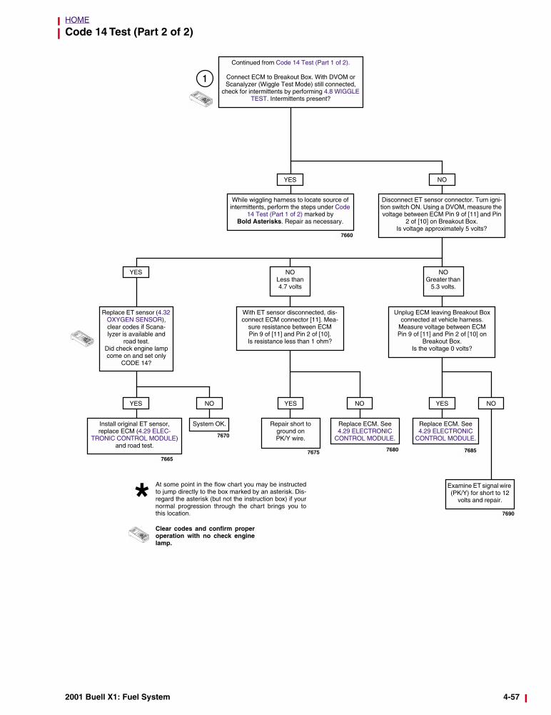
Code 14 Test (Part 2 of 2)
Continued from Code 14 Test (Part 1 of 2).
Connect ECM to Breakout Box. With DVOM or Scanalyzer (Wiggle Test Mode) still connected,
check for intermittents by performing 4.8 WIGGLE TEST. Intermittents present?
YES
While wiggling harness to locate source of intermittents, perform the steps under Code
14 Test (Part 1 of 2) marked by Bold Asterisks. Repair as necessary.
Disconnect ET sensor connector. Turn igni-tion switch ON. Using a DVOM, measure the voltage between ECM Pin 9 of [11] and Pin
2 of [10] on Breakout Box. Is voltage approximately 5 volts?
YES NOLess than 4.7 volts
NOGreater than
5.3 volts.
Replace ET sensor (4.32 OXYGEN SENSOR), clear codes if Scana-lyzer is available and
road test.Did check engine lamp come on and set only
CODE 14?
With ET sensor disconnected, dis-connect ECM connector [11]. Mea-
sure resistance between ECM Pin 9 of [11] and Pin 2 of [10]. Is resistance less than 1 ohm?
Unplug ECM leaving Breakout Box connected at vehicle harness.
Measure voltage between ECM Pin 9 of [11] and Pin 2 of [10] on
Breakout Box. Is the voltage 0 volts?
Install original ET sensor, replace ECM (4.29 ELEC-
TRONIC CONTROL MODULE) and road test.
YES
System OK. Repair short to ground onPK/Y wire.
YES YES
Examine ET signal wire (PK/Y) for short to 12
volts and repair.
NO
NO NO
Clear codes and confirm properoperation with no check enginelamp.
At some point in the flow chart you may be instructedto jump directly to the box marked by an asterisk. Dis-regard the asterisk (but not the instruction box) if yournormal progression through the chart brings you tothis location.
Replace ECM. See 4.29 ELECTRONIC
CONTROL MODULE.
Replace ECM. See 4.29 ELECTRONIC
CONTROL MODULE.
7660
7670
76657675 7680 7685
7690
1
NO
2001 Buell X1: Fuel System 4-57
HOME
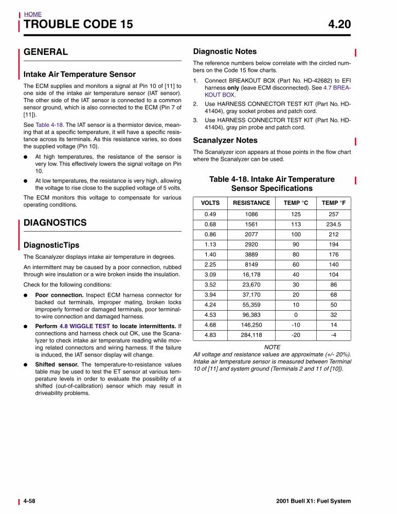
TROUBLE CODE 15 4.20
GENERAL
Intake Air Temperature SensorThe ECM supplies and monitors a signal at Pin 10 of [11] toone side of the intake air temperature sensor (IAT sensor).The other side of the IAT sensor is connected to a commonsensor ground, which is also connected to the ECM (Pin 7 of[11]).
See Table 4-18. The IAT sensor is a thermistor device, mean-ing that at a specific temperature, it will have a specific resis-tance across its terminals. As this resistance varies, so doesthe supplied voltage (Pin 10).
● At high temperatures, the resistance of the sensor isvery low. This effectively lowers the signal voltage on Pin10.
● At low temperatures, the resistance is very high, allowingthe voltage to rise close to the supplied voltage of 5 volts.
The ECM monitors this voltage to compensate for variousoperating conditions.
DIAGNOSTICS
DiagnosticTipsThe Scanalyzer displays intake air temperature in degrees.
An intermittent may be caused by a poor connection, rubbedthrough wire insulation or a wire broken inside the insulation.
Check for the following conditions:
● Poor connection. Inspect ECM harness connector forbacked out terminals, improper mating, broken locksimproperly formed or damaged terminals, poor terminal-to-wire connection and damaged harness.
● Perform 4.8 WIGGLE TEST to locate intermittents. Ifconnections and harness check out OK, use the Scana-lyzer to check intake air temperature reading while mov-ing related connectors and wiring harness. If the failureis induced, the IAT sensor display will change.
● Shifted sensor. The temperature-to-resistance valuestable may be used to test the ET sensor at various tem-perature levels in order to evaluate the possibility of ashifted (out-of-calibration) sensor which may result indriveability problems.
Diagnostic NotesThe reference numbers below correlate with the circled num-bers on the Code 15 flow charts.
1. Connect BREAKOUT BOX (Part No. HD-42682) to EFIharness only (leave ECM disconnected). See 4.7 BREA-KOUT BOX.
2. Use HARNESS CONNECTOR TEST KIT (Part No. HD-41404), gray socket probes and patch cord.
3. Use HARNESS CONNECTOR TEST KIT (Part No. HD-41404), gray pin probe and patch cord.
Scanalyzer NotesThe Scanalyzer icon appears at those points in the flow chartwhere the Scanalyzer can be used.
NOTEAll voltage and resistance values are approximate (+/- 20%).Intake air temperature sensor is measured between Terminal10 of [11] and system ground (Terminals 2 and 11 of [10]).
Table 4-18. Intake Air Temperature Sensor Specifications
VOLTS RESISTANCE TEMP °C TEMP °F
0.49 1086 125 257
0.68 1561 113 234.5
0.86 2077 100 212
1.13 2920 90 194
1.40 3889 80 176
2.25 8149 60 140
3.09 16,178 40 104
3.52 23,670 30 86
3.94 37,170 20 68
4.24 55,359 10 50
4.53 96,383 0 32
4.68 146,250 -10 14
4.83 284,118 -20 -4
4-58 2001 Buell X1: Fuel System
HOME
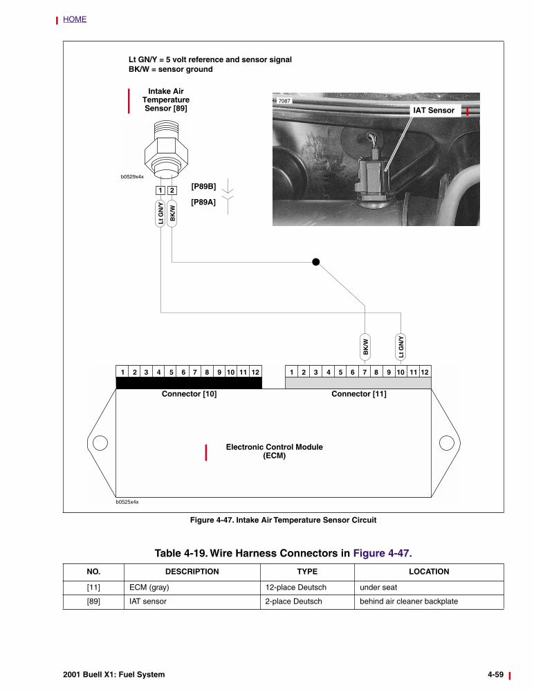
Figure 4-47. Intake Air Temperature Sensor Circuit
b0529x4xB
K/W
Electronic Control Module(ECM)
Connector [10] Connector [11]
Lt G
N/Y
Intake Air Temperature Sensor [89]
Lt GN/Y = 5 volt reference and sensor signalBK/W = sensor ground
1 2
BK
/W
Lt G
N/Y
IAT Sensor7087
[P89B]
[P89A]
Table 4-19. Wire Harness Connectors in Figure 4-47.
NO. DESCRIPTION TYPE LOCATION
[11] ECM (gray) 12-place Deutsch under seat
[89] IAT sensor 2-place Deutsch behind air cleaner backplate
2001 Buell X1: Fuel System 4-59
HOME
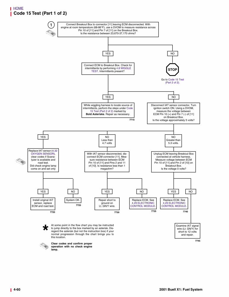
Code 15 Test (Part 1 of 2)
1
Go to Code 15 Test (Part 2 of 2).
Connect Breakout Box to connector [11] leaving ECM disconnected. With engine at room temperature (68-86°F), use a DVOM to measure resistance across
Pin 10 of [11] and Pin 7 of [11] on the Breakout Box. Is the resistance between 23,670-37,170 ohms?
YES
Connect ECM to Breakout Box. Check for intermittents by performing 4.8 WIGGLE
TEST. Intermittents present?
YES
While wiggling harness to locate source of intermittents, perform the steps under Code
15 Test (Part 2 of 2) marked by Bold Asterisks. Repair as necessary.
NO
Disconnect IAT sensor connector. Turn ignition switch ON. Using a DVOM,
measure the voltage between ECM Pin 10 (+) and Pin 7 (-) of [11]
on Breakout Box. Is the voltage approximately 5 volts?
YES NOLess than 4.7 volts
NOGreater than
5.3 volts.
Replace IAT sensor (4.32 OXYGEN SENSOR), clear codes if Scana-lyzer is available and
road test.Did check engine lamp come on and set only
With IAT sensor disconnected, dis-connect ECM connector [11]. Mea-
sure resistance between ECM Pin 10 of [11] and Pins 2 and 11of [10]. Is resistance less than 1
megaohm?
Unplug ECM leaving Breakout Box connected at vehicle harness.
Measure voltage between ECM Pin 10 of [11] and Pin 2 of [10] on
Breakout Box. Is the voltage 0 volts?
Install original IAT sensor, replace
ECM and road test.
YES
System OK.
YES
Examine IAT signal wire (Lt. GN/Y) for short to 12 volts
and repair.
NO NO
Clear codes and confirm properoperation with no check enginelamp.
At some point in the flow chart you may be instructedto jump directly to the box marked by an asterisk. Dis-regard the asterisk (but not the instruction box) if yournormal progression through the chart brings you tothis location.
STOP
Replace ECM. See 4.29 ELECTRONIC
CONTROL MODULE.
Replace ECM. See 4.29 ELECTRONIC
CONTROL MODULE.
Repair short to ground on
Lt. GN/Y wire.
YES
7715
7725
7720 77357730 7740
7745
NO
NO
4-60 2001 Buell X1: Fuel System
HOME
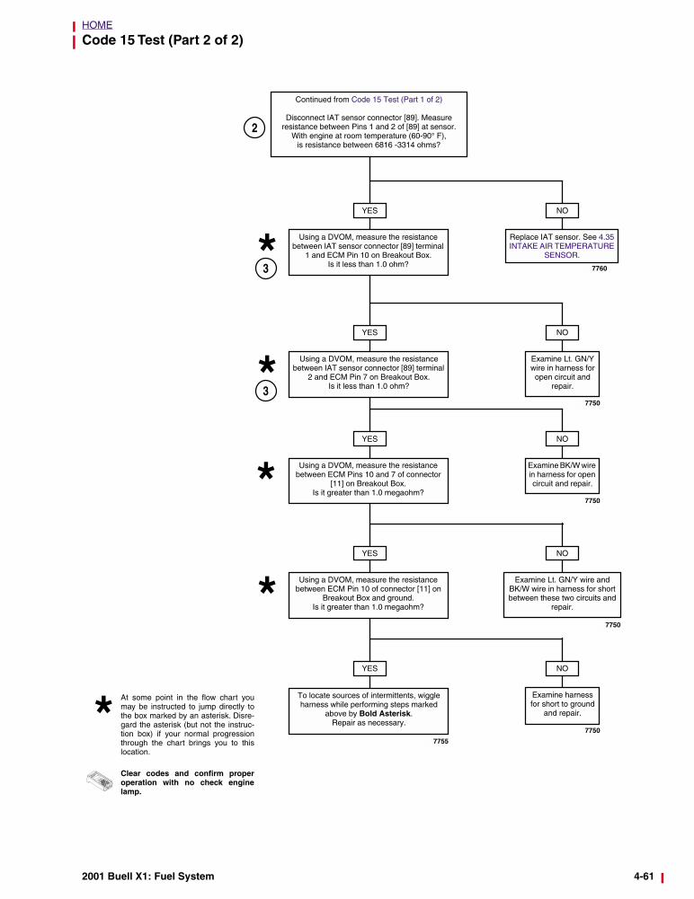
Code 15 Test (Part 2 of 2)
YES
Continued from Code 15 Test (Part 1 of 2)
Disconnect IAT sensor connector [89]. Measure resistance between Pins 1 and 2 of [89] at sensor.
With engine at room temperature (60-90° F), is resistance between 6816 -3314 ohms?
Using a DVOM, measure the resistance between IAT sensor connector [89] terminal
1 and ECM Pin 10 on Breakout Box.Is it less than 1.0 ohm?
NO
Replace IAT sensor. See 4.35 INTAKE AIR TEMPERATURE
SENSOR.
YES
Using a DVOM, measure the resistance between IAT sensor connector [89] terminal
2 and ECM Pin 7 on Breakout Box.Is it less than 1.0 ohm?
NO
Examine Lt. GN/Y wire in harness for open circuit and
repair.
YES
3
Using a DVOM, measure the resistance between ECM Pins 10 and 7 of connector
[11] on Breakout Box.Is it greater than 1.0 megaohm?
NO
Examine BK/W wire in harness for open circuit and repair.
YES
Using a DVOM, measure the resistance between ECM Pin 10 of connector [11] on
Breakout Box and ground.Is it greater than 1.0 megaohm?
NO
Examine Lt. GN/Y wire and BK/W wire in harness for short between these two circuits and
repair.
YES NO
Examine harness for short to ground
and repair.
To locate sources of intermittents, wiggle harness while performing steps marked
above by Bold Asterisk. Repair as necessary.
3
Clear codes and confirm properoperation with no check enginelamp.
At some point in the flow chart youmay be instructed to jump directly tothe box marked by an asterisk. Disre-gard the asterisk (but not the instruc-tion box) if your normal progressionthrough the chart brings you to thislocation.
2
7760
7750
7750
7750
7750
7755
2001 Buell X1: Fuel System 4-61
HOME
TROUBLE CODE 16 4.21
GENERAL
Battery VoltageA Code 16 will set if the ECM sees battery positive voltageless than 6 volts or greater than 18 volts.
● A low voltage condition typically occurs during activationof the starter or generally indicates loose wire connec-tions.
● A high voltage condition is usually caused by a faultyvoltage regulator.
DIAGNOSTICS
Diagnostic NotesThe reference numbers below correlate with the circled num-bers on the Code 16 flow charts.
1. The ECM is monitoring voltage at ECM connector [10](black) Terminal 1. Connect BREAKOUT BOX (Part No.HD-42682) to ECM. See 4.7 BREAKOUT BOX.
2. This checks for voltage drops in the ECM power circuit. Ifa significant voltage drop is not present, condition maybe caused by excessive starter current draw.
Scanalyzer NotesThe Scanalyzer icon appears at those points in the flow chartwhere the Scanalyzer can be used.
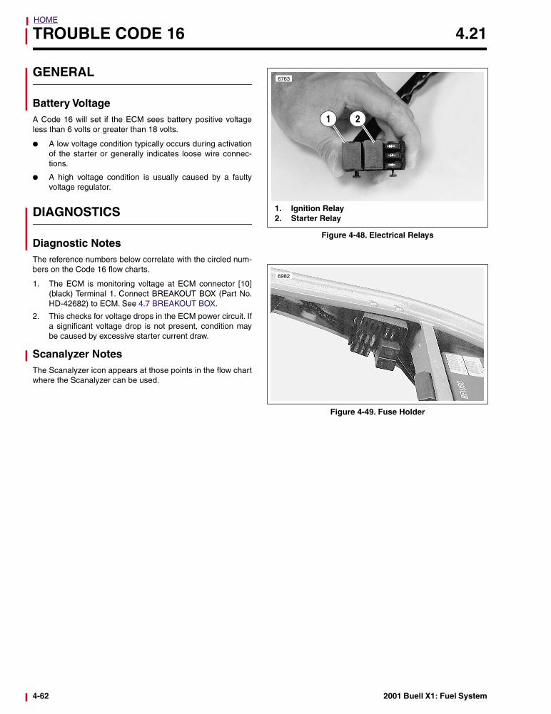
Figure 4-48. Electrical Relays
Figure 4-49. Fuse Holder
6763
1 2
1. Ignition Relay2. Starter Relay
6982
4-62 2001 Buell X1: Fuel System
HOME
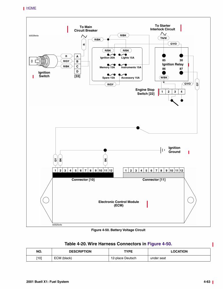
Figure 4-50. Battery Voltage Circuit
Electronic Control Module(ECM)
Connector [10] Connector [11]
BK
BK
IgnitionGround
R
R
R/GY
R/BK
R/GY
R/BK
R/BK
R/BK R/BK
GY/O
Ignition 20A
Memory 15A
Spare 15A
Lights 15A
Instruments 15A
Accessory 15A
Ignition Switch [33]
Engine StopSwitch [22]
TN/W
Ignition Relay
W/BK
GY/O
To Main Circuit Breaker
To Starter Interlock Circuit
GY
GY
Table 4-20. Wire Harness Connectors in Figure 4-50.
NO. DESCRIPTION TYPE LOCATION
[10] ECM (black) 12-place Deutsch under seat
2001 Buell X1: Fuel System 4-63
HOME
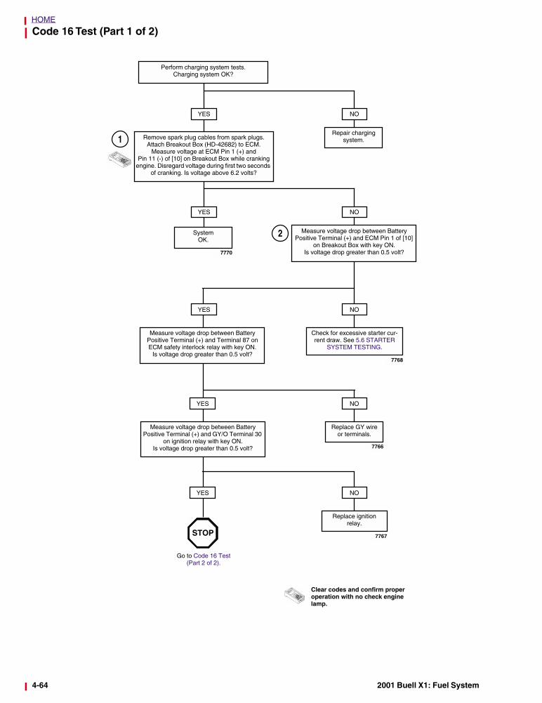
Code 16 Test (Part 1 of 2)
Perform charging system tests. Charging system OK?
YES NO
Repair chargingsystem.Remove spark plug cables from spark plugs.
Attach Breakout Box (HD-42682) to ECM. Measure voltage at ECM Pin 1 (+) and
Pin 11 (-) of [10] on Breakout Box while cranking engine. Disregard voltage during first two seconds
of cranking. Is voltage above 6.2 volts?
YES NO
Measure voltage drop between Battery Positive Terminal (+) and ECM Pin 1 of [10]
on Breakout Box with key ON. Is voltage drop greater than 0.5 volt?
System OK.
YES NO
Check for excessive starter cur-rent draw. See 5.6 STARTER
SYSTEM TESTING.
Measure voltage drop between Battery Positive Terminal (+) and Terminal 87 on ECM safety interlock relay with key ON.
Is voltage drop greater than 0.5 volt?
NO
Replace ignitionrelay.
1
2
Clear codes and confirm proper operation with no check engine lamp.
YES
Measure voltage drop between Battery Positive Terminal (+) and GY/O Terminal 30
on ignition relay with key ON.Is voltage drop greater than 0.5 volt?
YES
Go to Code 16 Test (Part 2 of 2).
STOP
Replace GY wire or terminals.
NO
7770
7768
7766
7767
4-64 2001 Buell X1: Fuel System
HOME
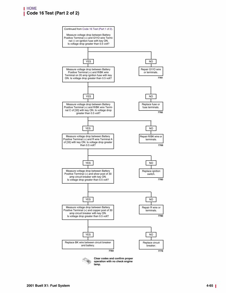
Code 16 Test (Part 2 of 2)
Continued from Code 16 Test (Part 1 of 2).
Measure voltage drop between Battery Positive Terminal (+) and GY/O wire Termi-
nal (-) on ignition fuse with key ON.Is voltage drop greater than 0.5 volt?
NO
Replace fuse or fuse terminals.
YES
Measure voltage drop between Battery Positive Terminal (+) and R wire Terminal A of [33] with key ON. Is voltage drop greater
than 0.5 volt?
YES NO
Replace ignitionswitch.
Clear codes and confirm proper operation with no check engine lamp.
Measure voltage drop between Battery Positive Terminal (+) and silver post of 30
amp circuit breaker with key ON. Is voltage drop greater than 0.5 volt?
YES NO
Repair R wire or terminals.
Measure voltage drop between Battery Positive Terminal (+) and copper post of 30
amp circuit breaker with key ON. Is voltage drop greater than 0.5 volt?
YES NO
Replace circuit breaker.
Replace BK wire between circuit breaker and battery.
7781
YES
Measure voltage drop between Battery Positive Terminal (+) and R/BK wire
Terminal on 20 amp ignition fuse with key ON. Is voltage drop greater than 0.5 volt?
YES
Measure voltage drop between Battery Positive Terminal (+) and R/BK wire Termi-nal C of [33] with key ON. Is voltage drop
greater than 0.5 volt?
NO
Repair GY/O wire or terminals.
NO
Repair R/BK wire or terminals.
7782
7769
7783
7780
77797784
2001 Buell X1: Fuel System 4-65
HOME
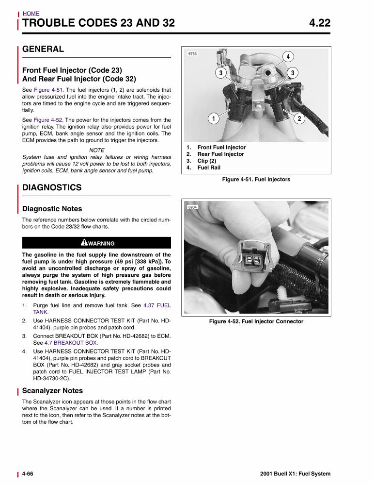
TROUBLE CODES 23 AND 32 4.22
GENERAL
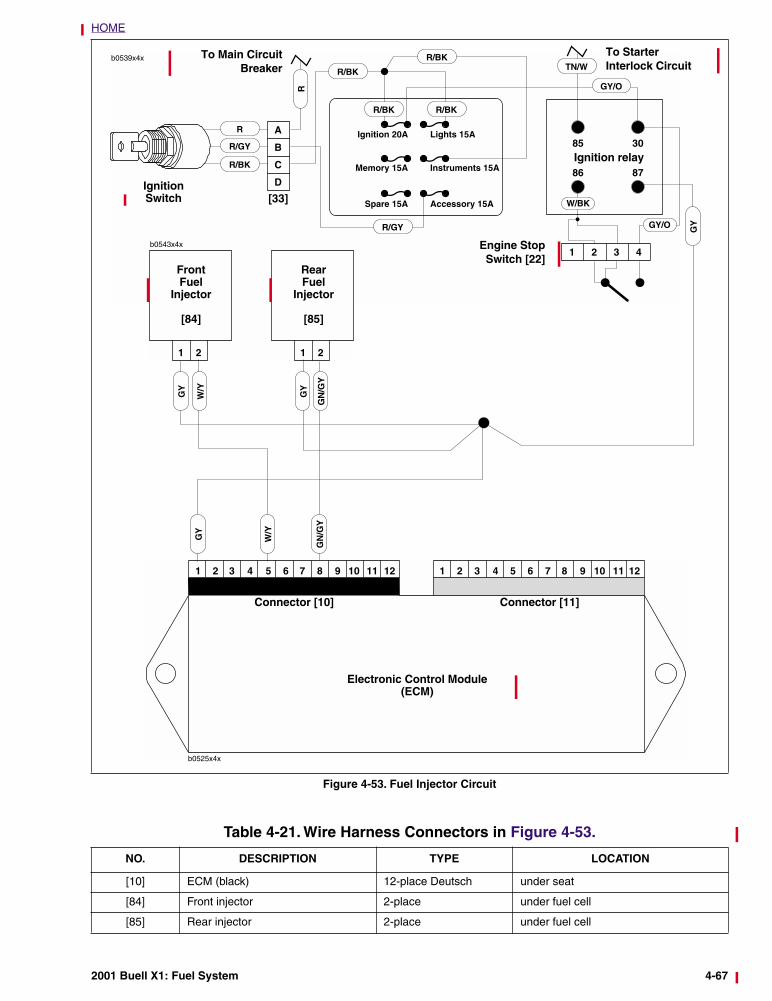
Front Fuel Injector (Code 23)And Rear Fuel Injector (Code 32)See Figure 4-51. The fuel injectors (1, 2) are solenoids thatallow pressurized fuel into the engine intake tract. The injec-tors are timed to the engine cycle and are triggered sequen-tially.
See Figure 4-52. The power for the injectors comes from theignition relay. The ignition relay also provides power for fuelpump, ECM, bank angle sensor and the ignition coils. TheECM provides the path to ground to trigger the injectors.
NOTESystem fuse and ignition relay failures or wiring harnessproblems will cause 12 volt power to be lost to both injectors,ignition coils, ECM, bank angle sensor and fuel pump.
DIAGNOSTICS
Diagnostic NotesThe reference numbers below correlate with the circled num-bers on the Code 23/32 flow charts.
1WARNING1WARNING
The gasoline in the fuel supply line downstream of thefuel pump is under high pressure (49 psi [338 kPa]). Toavoid an uncontrolled discharge or spray of gasoline,always purge the system of high pressure gas beforeremoving fuel tank. Gasoline is extremely flammable andhighly explosive. Inadequate safety precautions couldresult in death or serious injury.
1. Purge fuel line and remove fuel tank. See 4.37 FUELTANK.
2. Use HARNESS CONNECTOR TEST KIT (Part No. HD-41404), purple pin probes and patch cord.
3. Connect BREAKOUT BOX (Part No. HD-42682) to ECM.See 4.7 BREAKOUT BOX.
4. Use HARNESS CONNECTOR TEST KIT (Part No. HD-41404), purple pin probes and patch cord to BREAKOUTBOX (Part No. HD-42682) and gray socket probes andpatch cord to FUEL INJECTOR TEST LAMP (Part No.HD-34730-2C).
Scanalyzer NotesThe Scanalyzer icon appears at those points in the flow chartwhere the Scanalyzer can be used. If a number is printednext to the icon, then refer to the Scanalyzer notes at the bot-tom of the flow chart.
Figure 4-51. Fuel Injectors
Figure 4-52. Fuel Injector Connector
6765
1. Front Fuel Injector2. Rear Fuel Injector3. Clip (2) 4. Fuel Rail
2
3
4
1
3
6934
4-66 2001 Buell X1: Fuel System
HOME
Figure 4-53. Fuel Injector Circuit
R
R
R/GY
R/BK
R/GY
R/BK
R/BK
R/BK R/BK
GY/O
Ignition 20A
Memory 15A
Spare 15A
Lights 15A
Instruments 15A
Accessory 15A
Ignition Switch [33]
Engine StopSwitch [22]
TN/W
Ignition relay
W/BK
GY/O
To Main CircuitBreaker
To Starter Interlock Circuit
Electronic Control Module(ECM)
Connector [10] Connector [11]
GY
b0543x4x
1 2 1 2
RearFuel
Injector
[85]
FrontFuel
Injector
[84]
W/Y
W/Y
GN
/GY
GY
GN
/GY
GY
GY
Table 4-21. Wire Harness Connectors in Figure 4-53.
NO. DESCRIPTION TYPE LOCATION
[10] ECM (black) 12-place Deutsch under seat
[84] Front injector 2-place under fuel cell
[85] Rear injector 2-place under fuel cell
2001 Buell X1: Fuel System 4-67
HOME
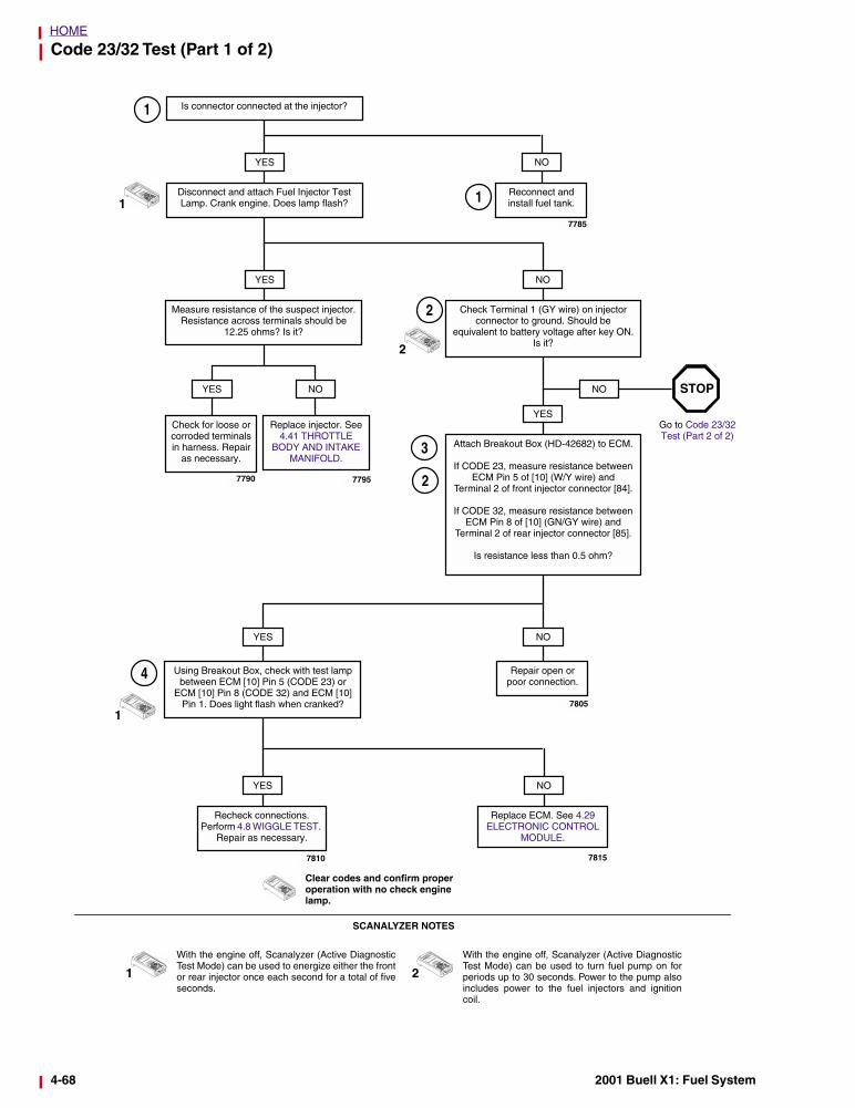
Code 23/32 Test (Part 1 of 2)
Clear codes and confirm proper operation with no check engine lamp.
Is connector connected at the injector?
YES NO
Reconnect and install fuel tank.
YES
Disconnect and attach Fuel Injector Test Lamp. Crank engine. Does lamp flash?
1
1
Measure resistance of the suspect injector. Resistance across terminals should be
12.25 ohms? Is it?
Check Terminal 1 (GY wire) on injector connector to ground. Should be
equivalent to battery voltage after key ON. Is it?
NO
Attach Breakout Box (HD-42682) to ECM.
If CODE 23, measure resistance between ECM Pin 5 of [10] (W/Y wire) and
Terminal 2 of front injector connector [84].
If CODE 32, measure resistance between ECM Pin 8 of [10] (GN/GY wire) and
Terminal 2 of rear injector connector [85].
Is resistance less than 0.5 ohm?
YESCheck for loose or corroded terminals in harness. Repair
as necessary.
Replace injector. See 4.41 THROTTLE
BODY AND INTAKE MANIFOLD.
YES NO NO
Go to Code 23/32 Test (Part 2 of 2)
YES NO
Repair open orpoor connection.
Using Breakout Box, check with test lamp between ECM [10] Pin 5 (CODE 23) or
ECM [10] Pin 8 (CODE 32) and ECM [10] Pin 1. Does light flash when cranked?
YES NO
Recheck connections. Perform 4.8 WIGGLE TEST.
Repair as necessary.
2
2
2
1
4
1
With the engine off, Scanalyzer (Active DiagnosticTest Mode) can be used to energize either the frontor rear injector once each second for a total of fiveseconds.
2
With the engine off, Scanalyzer (Active DiagnosticTest Mode) can be used to turn fuel pump on forperiods up to 30 seconds. Power to the pump alsoincludes power to the fuel injectors and ignitioncoil.
SCANALYZER NOTES
STOP
Replace ECM. See 4.29 ELECTRONIC CONTROL
MODULE.
3
7785
1
7790 7795
7805
78157810
4-68 2001 Buell X1: Fuel System
HOME
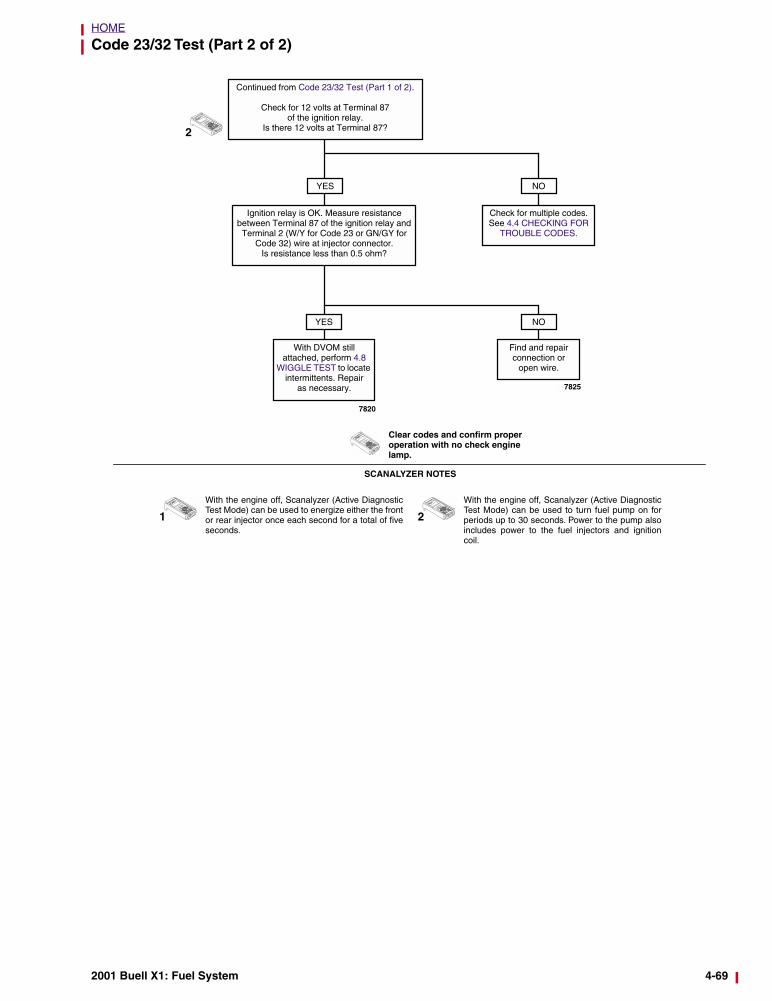
Code 23/32 Test (Part 2 of 2)
Clear codes and confirm proper operation with no check engine lamp.
NO
2
Continued from Code 23/32 Test (Part 1 of 2).
Check for 12 volts at Terminal 87 of the ignition relay.
Is there 12 volts at Terminal 87?
YES
Ignition relay is OK. Measure resistance between Terminal 87 of the ignition relay and Terminal 2 (W/Y for Code 23 or GN/GY for
Code 32) wire at injector connector.Is resistance less than 0.5 ohm?
With DVOM still attached, perform 4.8
WIGGLE TEST to locate intermittents. Repair
as necessary.
Find and repair connection or
open wire.
YES NO
1
With the engine off, Scanalyzer (Active DiagnosticTest Mode) can be used to energize either the frontor rear injector once each second for a total of fiveseconds.
2
With the engine off, Scanalyzer (Active DiagnosticTest Mode) can be used to turn fuel pump on forperiods up to 30 seconds. Power to the pump alsoincludes power to the fuel injectors and ignitioncoil.
SCANALYZER NOTES
Check for multiple codes. See 4.4 CHECKING FOR
TROUBLE CODES.
7825
7820
2001 Buell X1: Fuel System 4-69
HOME
TROUBLE CODES 24 AND 25 4.23
GENERAL
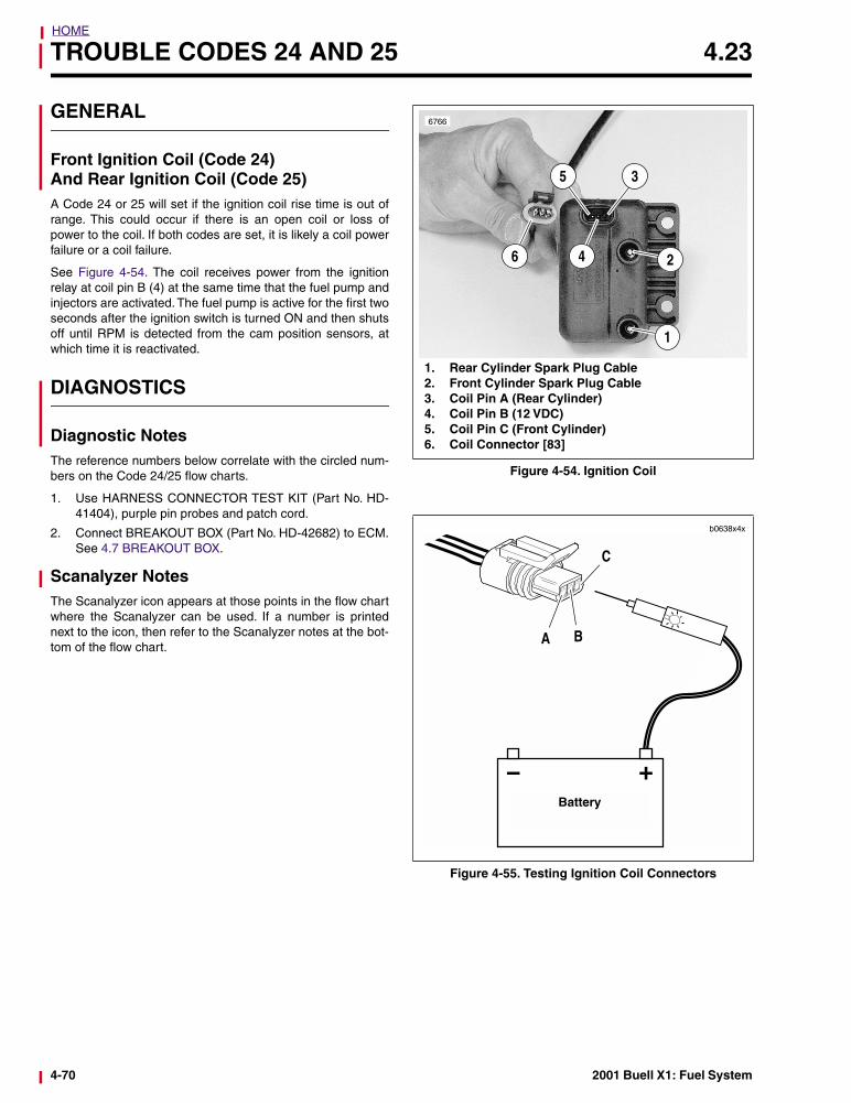
Front Ignition Coil (Code 24)And Rear Ignition Coil (Code 25)A Code 24 or 25 will set if the ignition coil rise time is out ofrange. This could occur if there is an open coil or loss ofpower to the coil. If both codes are set, it is likely a coil powerfailure or a coil failure.
See Figure 4-54. The coil receives power from the ignitionrelay at coil pin B (4) at the same time that the fuel pump andinjectors are activated. The fuel pump is active for the first twoseconds after the ignition switch is turned ON and then shutsoff until RPM is detected from the cam position sensors, atwhich time it is reactivated.
DIAGNOSTICS
Diagnostic NotesThe reference numbers below correlate with the circled num-bers on the Code 24/25 flow charts.
1. Use HARNESS CONNECTOR TEST KIT (Part No. HD-41404), purple pin probes and patch cord.
2. Connect BREAKOUT BOX (Part No. HD-42682) to ECM.See 4.7 BREAKOUT BOX.
Scanalyzer NotesThe Scanalyzer icon appears at those points in the flow chartwhere the Scanalyzer can be used. If a number is printednext to the icon, then refer to the Scanalyzer notes at the bot-tom of the flow chart.
Figure 4-54. Ignition Coil
Figure 4-55. Testing Ignition Coil Connectors
1
6766
2
35
4
1. Rear Cylinder Spark Plug Cable2. Front Cylinder Spark Plug Cable3. Coil Pin A (Rear Cylinder)4. Coil Pin B (12 VDC)5. Coil Pin C (Front Cylinder)6. Coil Connector [83]
6
+
b0638x4x
A B
C
Battery
4-70 2001 Buell X1: Fuel System
HOME
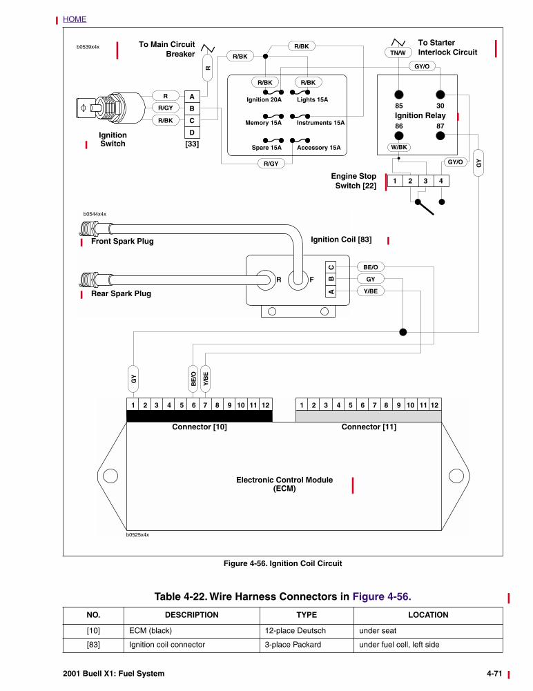
Figure 4-56. Ignition Coil Circuit
b0544x4x
AB
C
FR
Ignition Coil [83]
Electronic Control Module(ECM)
Connector [10] Connector [11]
GY
GY
BE/O
BE
/O
R
R
R/GY
R/BK
R/GY
R/BK
R/BK
R/BK R/BK
GY/O
Ignition 20A
Memory 15A
Spare 15A
Lights 15A
Instruments 15A
Accessory 15A
Ignition Switch [33]
Engine StopSwitch [22]
TN/W
Ignition Relay
W/BK
GY/O
To Main CircuitBreaker
To Starter Interlock Circuit
GY
Front Spark Plug
Rear Spark Plug
Y/B
E
Y/BE
Table 4-22. Wire Harness Connectors in Figure 4-56.
NO. DESCRIPTION TYPE LOCATION
[10] ECM (black) 12-place Deutsch under seat
[83] Ignition coil connector 3-place Packard under fuel cell, left side
2001 Buell X1: Fuel System 4-71
HOME
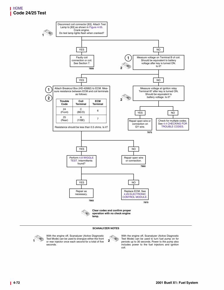
Code 24/25 Test
NO
Measure voltage on Terminal B of coil. Should be equivalent to batteryvoltage after key is turned ON.
Is it?
1
YES
Faulty coilconnection or coil.
See Section 7.
Disconnect coil connector [83]. Attach Test Lamp to [83] as shown in Figure 4-55.
Crank engine. Do test lamp lights flash when cranked?
NOYES
Measure voltage at ignition relay Terminal 87 after key is turned ON.
Should be equivalent to battery voltage. Is it?
YES
Repair open wire or connection on
GY wire.
NO
Check for multiple codes. See 4.4 CHECKING FOR
TROUBLE CODES.
Attach Breakout Box (HD-42682) to ECM. Mea-sure resistance between ECM and coil terminals
as follows:
Resistance should be less than 0.5 ohms. Is it?
Trouble Code
Coil Terminal
ECMTerminal
24 (Front)
C (BE/O) 6
25 (Rear)
A(Y/BE) 7
NO
Repair open wire or connection.
YES
Perform 4.8 WIGGLE TEST. Intermittents
found?
NOYES
Repair as necessary.
2
2
1
1
With the engine off, Scanalyzer (Active DiagnosticTest Mode) can be used to energize either the frontor rear injector once each second for a total of fiveseconds.
2
With the engine off, Scanalyzer (Active DiagnosticTest Mode) can be used to turn fuel pump on forperiods up to 30 seconds. Power to the pump alsoincludes power to the fuel injectors and ignitioncoil.
SCANALYZER NOTES
Clear codes and confirm proper operation with no check engine lamp.
Replace ECM. See 4.29 ELECTRONIC
CONTROL MODULE.
1
2
7856
7875
7860
78707865
4-72 2001 Buell X1: Fuel System
HOME
TROUBLE CODE 33 4.24
GENERAL
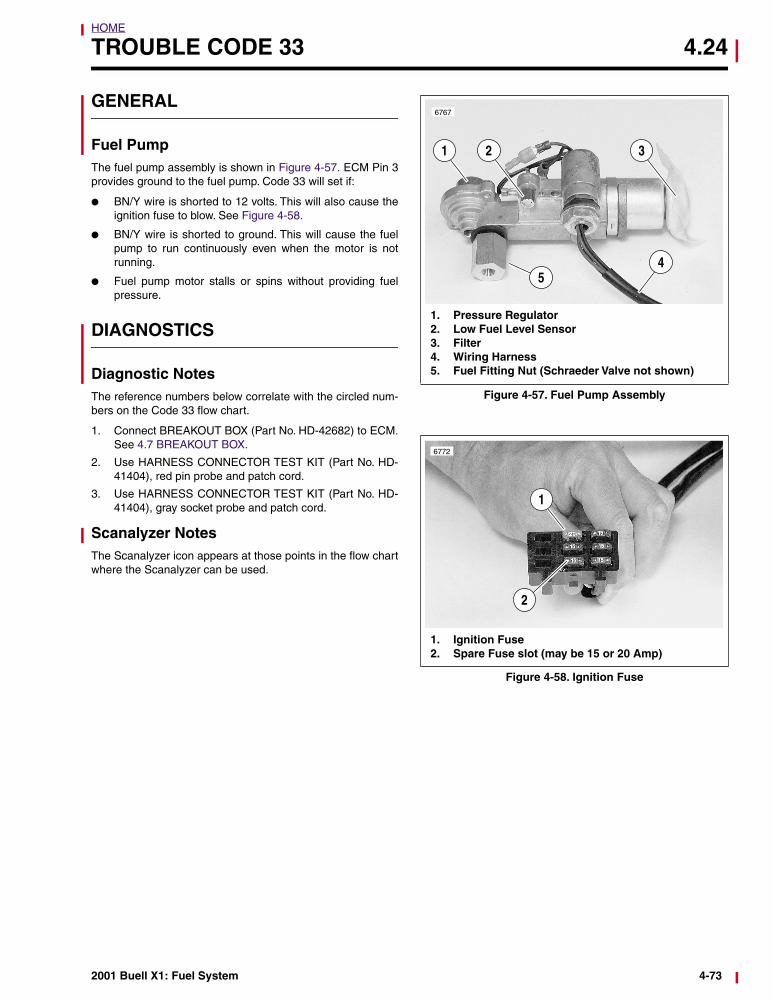
Fuel PumpThe fuel pump assembly is shown in Figure 4-57. ECM Pin 3provides ground to the fuel pump. Code 33 will set if:
● BN/Y wire is shorted to 12 volts. This will also cause theignition fuse to blow. See Figure 4-58.
● BN/Y wire is shorted to ground. This will cause the fuelpump to run continuously even when the motor is notrunning.
● Fuel pump motor stalls or spins without providing fuelpressure.
DIAGNOSTICS
Diagnostic NotesThe reference numbers below correlate with the circled num-bers on the Code 33 flow chart.
1. Connect BREAKOUT BOX (Part No. HD-42682) to ECM.See 4.7 BREAKOUT BOX.
2. Use HARNESS CONNECTOR TEST KIT (Part No. HD-41404), red pin probe and patch cord.
3. Use HARNESS CONNECTOR TEST KIT (Part No. HD-41404), gray socket probe and patch cord.
Scanalyzer NotesThe Scanalyzer icon appears at those points in the flow chartwhere the Scanalyzer can be used.
Figure 4-57. Fuel Pump Assembly
Figure 4-58. Ignition Fuse
5
6767
1 2 3
4
1. Pressure Regulator2. Low Fuel Level Sensor3. Filter4. Wiring Harness5. Fuel Fitting Nut (Schraeder Valve not shown)
1. Ignition Fuse2. Spare Fuse slot (may be 15 or 20 Amp)
1
2
6772
2001 Buell X1: Fuel System 4-73
HOME
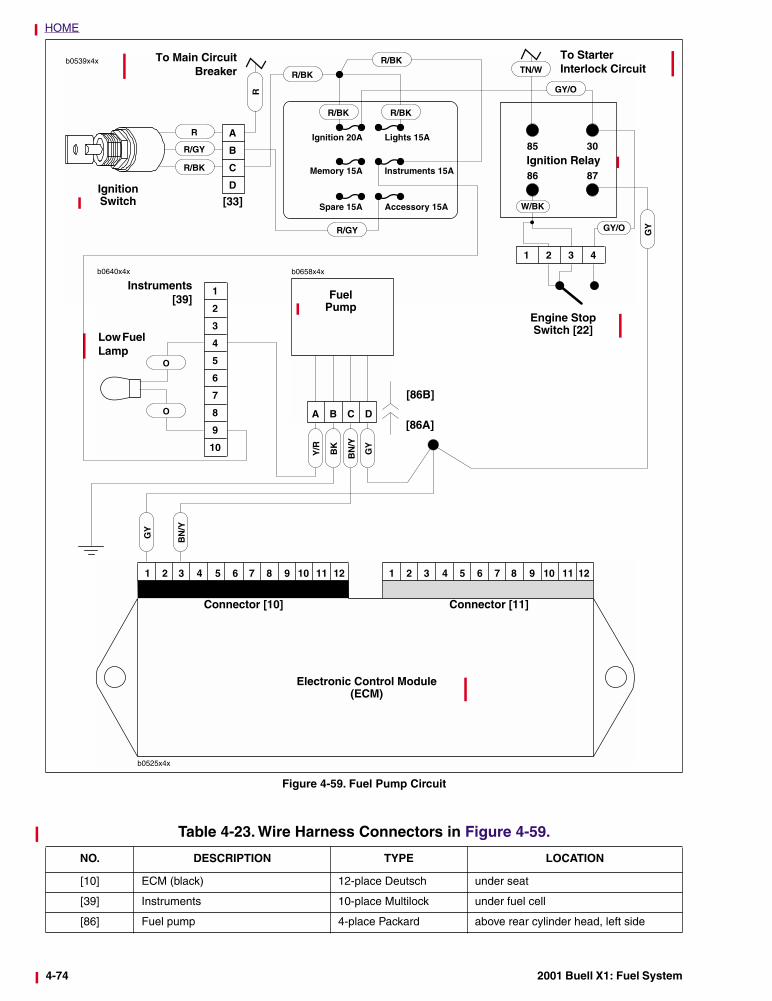
Figure 4-59. Fuel Pump Circuit
b0640x4x
R
R
R/GY
R/BK
R/GY
R/BK
R/BK
R/BK R/BK
GY/O
Ignition 20A
Memory 15A
Spare 15A
Lights 15A
Instruments 15A
Accessory 15A
Ignition Switch [33]
Engine Stop Switch [22]
TN/W
Ignition Relay
W/BK
GY/O
To Main CircuitBreaker
To Starter Interlock Circuit
GY
Low Fuel Lamp
GY
BN
/Y
Electronic Control Module(ECM)
Connector [10] Connector [11]
O
O
Instruments[39]
GY
BN
/Y
BK
Y/R
FuelPump
[86B]
[86A]
Table 4-23. Wire Harness Connectors in Figure 4-59.
NO. DESCRIPTION TYPE LOCATION
[10] ECM (black) 12-place Deutsch under seat
[39] Instruments 10-place Multilock under fuel cell
[86] Fuel pump 4-place Packard above rear cylinder head, left side
4-74 2001 Buell X1: Fuel System
HOME
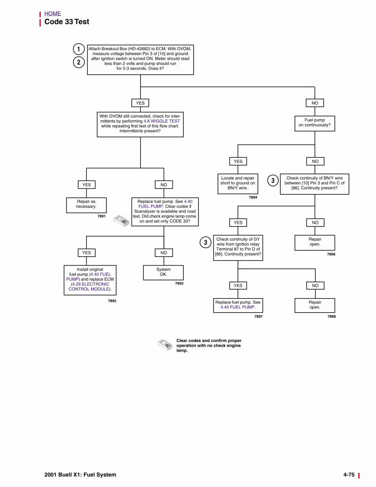
Code 33 Test
YES
With DVOM still connected, check for inter-mittents by performing 4.8 WIGGLE TEST while repeating first test of this flow chart.
Intermittents present?
Attach Breakout Box (HD-42682) to ECM. With DVOM, measure voltage between Pin 3 of [10] and ground
after ignition switch is turned ON. Meter should read less than 2 volts and pump should run
for 2-3 seconds. Does it?
YES NO
Repair as necessary.
Replace fuel pump. See 4.40 FUEL PUMP. Clear codes if
Scanalyzer is available and road test. Did check engine lamp come
on and set only CODE 33?
YES NO
Install original fuel pump (4.40 FUEL
PUMP) and replace ECM (4.29 ELECTRONIC
CONTROL MODULE).
SystemOK.
Fuel pump on continuously?
YES
Locate and repair short to ground on
BN/Y wire.
NO
Check continuity of BN/Y wire between [10] Pin 3 and Pin C of
[86]. Continuity present?
YES
Repairopen.
NO
Check continuity of GY wire from ignition relay Terminal 87 to Pin D of
[86]. Continuity present?
YES
Replace fuel pump. See 4.40 FUEL PUMP.
Repairopen.
NO
Clear codes and confirm proper operation with no check engine lamp.
NO
1
2
3
3
7891
7892
7893
7896
78987897
7894
2001 Buell X1: Fuel System 4-75
HOME
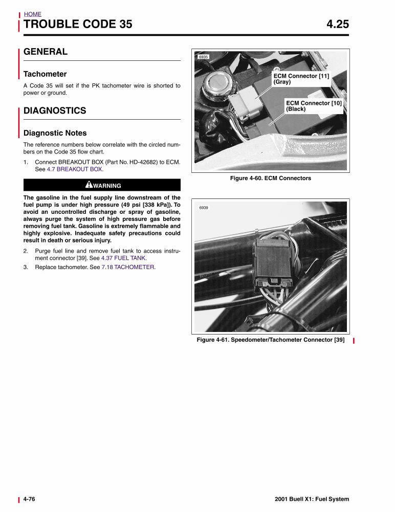
TROUBLE CODE 35 4.25
GENERAL
TachometerA Code 35 will set if the PK tachometer wire is shorted topower or ground.
DIAGNOSTICS
Diagnostic NotesThe reference numbers below correlate with the circled num-bers on the Code 35 flow chart.
1. Connect BREAKOUT BOX (Part No. HD-42682) to ECM.See 4.7 BREAKOUT BOX.
1WARNING1WARNING
The gasoline in the fuel supply line downstream of thefuel pump is under high pressure (49 psi [338 kPa]). Toavoid an uncontrolled discharge or spray of gasoline,always purge the system of high pressure gas beforeremoving fuel tank. Gasoline is extremely flammable andhighly explosive. Inadequate safety precautions couldresult in death or serious injury.
2. Purge fuel line and remove fuel tank to access instru-ment connector [39]. See 4.37 FUEL TANK.
3. Replace tachometer. See 7.18 TACHOMETER.
Figure 4-60. ECM Connectors
Figure 4-61. Speedometer/Tachometer Connector [39]
6935
ECM Connector [10](Black)
ECM Connector [11](Gray)
6939
4-76 2001 Buell X1: Fuel System
HOME
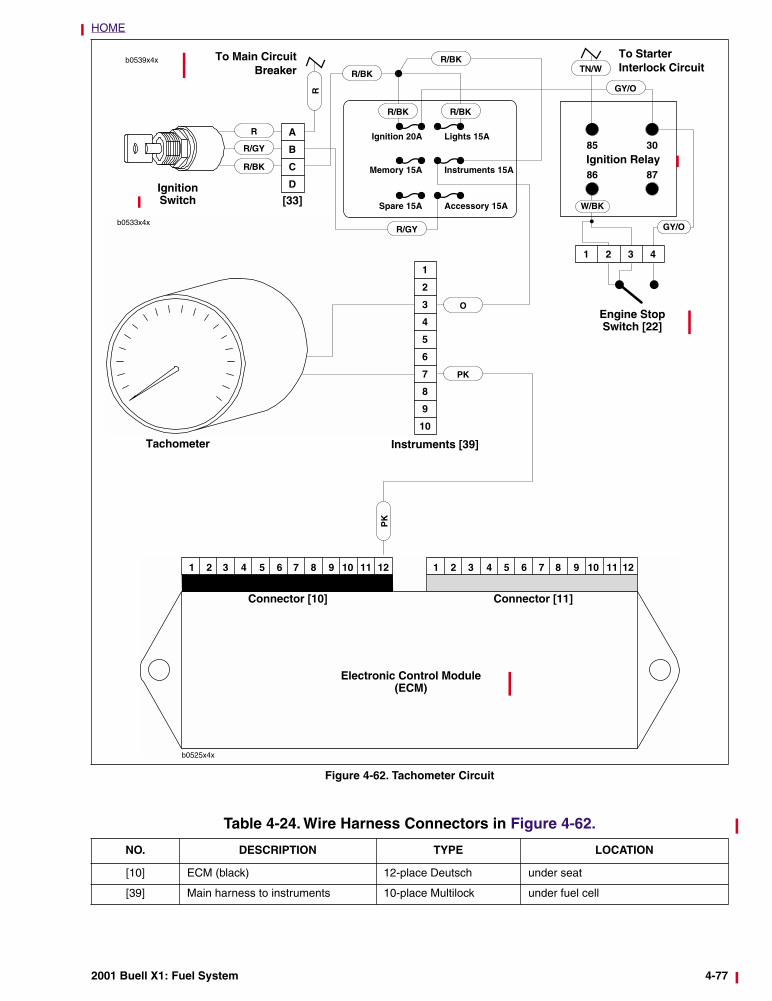
Figure 4-62. Tachometer Circuit
1
2
3
4
5
6
7
8
9
10
b0533x4x
R
R
R/GY
R/BK
R/GY
R/BK
R/BK
R/BK R/BK
GY/O
Ignition 20A
Memory 15A
Spare 15A
Lights 15A
Instruments 15A
Accessory 15A
Ignition Switch [33]
Engine Stop Switch [22]
TN/W
Ignition Relay
W/BK
GY/O
To Main CircuitBreaker
Instruments [39]Tachometer
PKP
K
To Starter Interlock Circuit
O
Electronic Control Module(ECM)
Connector [10] Connector [11]
Table 4-24. Wire Harness Connectors in Figure 4-62.
NO. DESCRIPTION TYPE LOCATION
[10] ECM (black) 12-place Deutsch under seat
[39] Main harness to instruments 10-place Multilock under fuel cell
2001 Buell X1: Fuel System 4-77
HOME
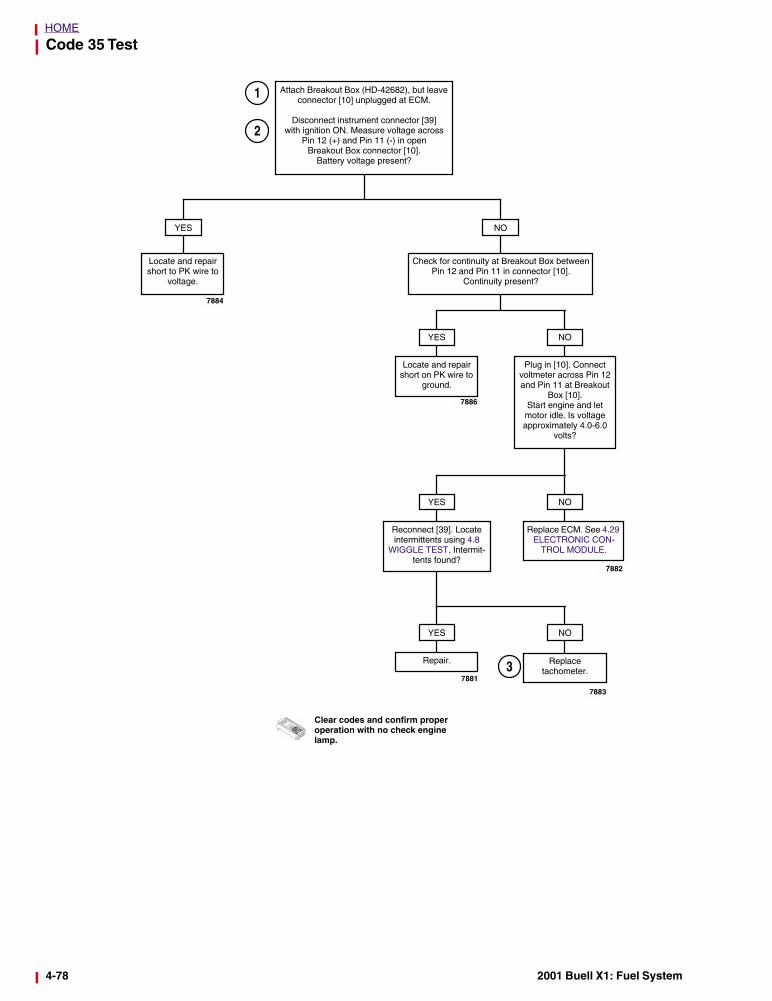
Code 35 Test
Attach Breakout Box (HD-42682), but leave connector [10] unplugged at ECM.
Disconnect instrument connector [39] with ignition ON. Measure voltage across
Pin 12 (+) and Pin 11 (-) in open Breakout Box connector [10].
Battery voltage present?
YES
Locate and repair short to PK wire to
voltage.
NO
Check for continuity at Breakout Box betweenPin 12 and Pin 11 in connector [10].
Continuity present?
Locate and repair short on PK wire to
ground.
YES
Plug in [10]. Connect voltmeter across Pin 12 and Pin 11 at Breakout
Box [10]. Start engine and let motor idle. Is voltage approximately 4.0-6.0
volts?
NO
Clear codes and confirm proper operation with no check engine lamp.
Reconnect [39]. Locate intermittents using 4.8
WIGGLE TEST. Intermit-tents found?
YES
Replace ECM. See 4.29 ELECTRONIC CON-
TROL MODULE.
NO
Repair.
YES NO
Replace tachometer.
1
7884
7886
7883
7882
7881
2
3
4-78 2001 Buell X1: Fuel System
HOME
TROUBLE CODE 44 4.26
GENERAL
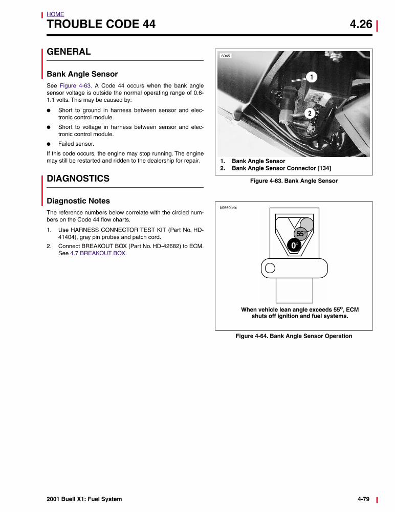
Bank Angle SensorSee Figure 4-63. A Code 44 occurs when the bank anglesensor voltage is outside the normal operating range of 0.6-1.1 volts. This may be caused by:
● Short to ground in harness between sensor and elec-tronic control module.
● Short to voltage in harness between sensor and elec-tronic control module.
● Failed sensor.
If this code occurs, the engine may stop running. The enginemay still be restarted and ridden to the dealership for repair.
DIAGNOSTICS
Diagnostic NotesThe reference numbers below correlate with the circled num-bers on the Code 44 flow charts.
1. Use HARNESS CONNECTOR TEST KIT (Part No. HD-41404), gray pin probes and patch cord.
2. Connect BREAKOUT BOX (Part No. HD-42682) to ECM.See 4.7 BREAKOUT BOX.
Figure 4-63. Bank Angle Sensor
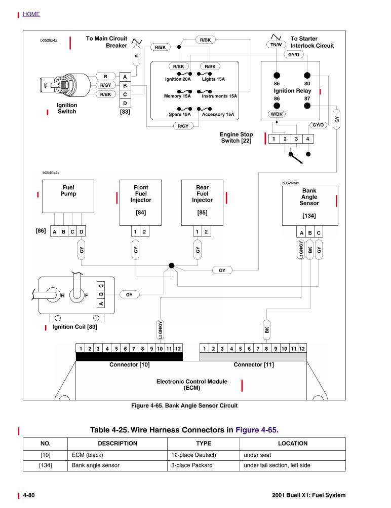
Figure 4-64. Bank Angle Sensor Operation
1
6945
2
1. Bank Angle Sensor2. Bank Angle Sensor Connector [134]
When vehicle lean angle exceeds 55o, ECM shuts off ignition and fuel systems.
b0660a4x
2001 Buell X1: Fuel System 4-79
HOME
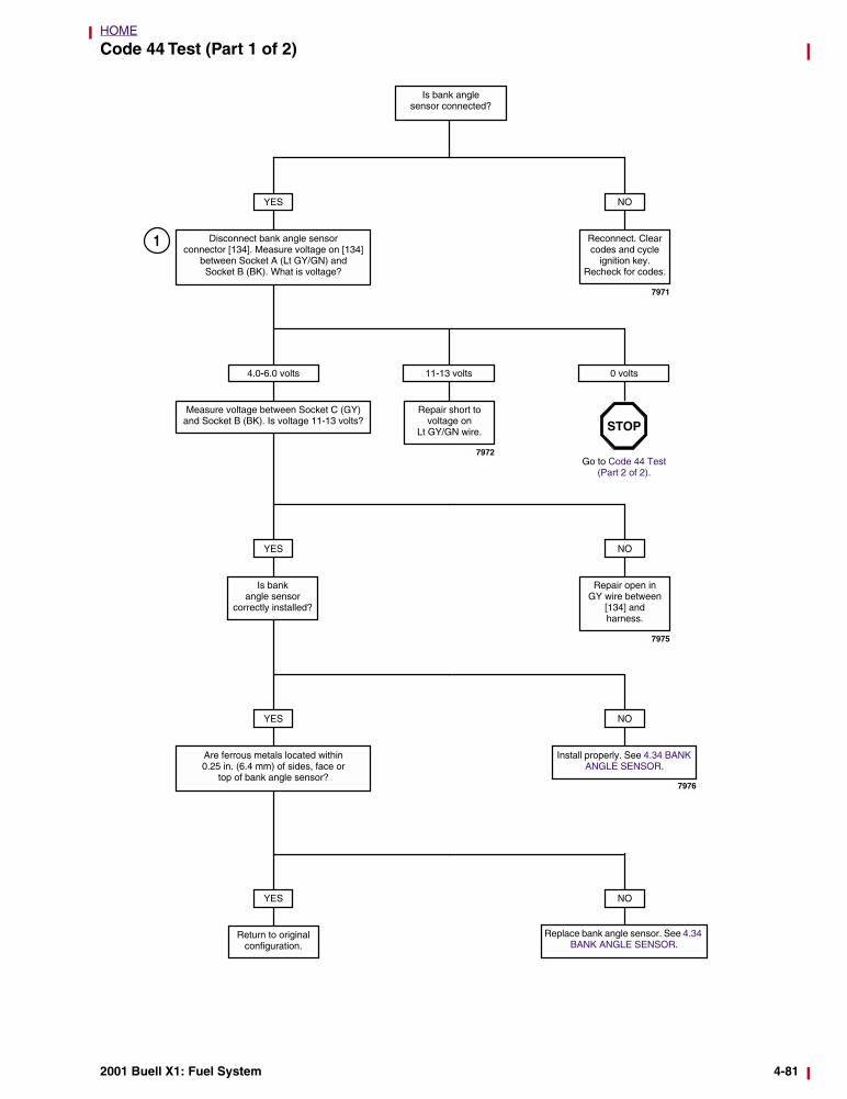
Figure 4-65. Bank Angle Sensor Circuit
b0540x4x
A B C D 1 2
ABFR
C
1 2
Electronic Control Module (ECM)
Connector [10] Connector [11]
RearFuel
Injector
[85]
FrontFuel
Injector
[84]
FuelPump
CBA
b0526x4x
BankAngle
Sensor
[134]
Ignition Coil [83]
GY
Lt G
N/G
Y
BK
GY
GY
Lt G
N/G
Y
BK
GY
GY
R
R
R/GY
R/BK
R/GY
R/BK
R/BK
R/BK R/BK
GY/O
Ignition 20A
Memory 15A
Spare 15A
Lights 15A
Instruments 15A
Accessory 15A
Ignition Switch [33]
Engine Stop Switch [22]
TN/W
Ignition Relay
W/BK
GY/O
To Main CircuitBreaker
To Starter Interlock Circuit
GY
GY
[86]
Table 4-25. Wire Harness Connectors in Figure 4-65.
NO. DESCRIPTION TYPE LOCATION
[10] ECM (black) 12-place Deutsch under seat
[134] Bank angle sensor 3-place Packard under tail section, left side
4-80 2001 Buell X1: Fuel System
HOME
Code 44 Test (Part 1 of 2)
Is bank angle sensor connected?
YES
Disconnect bank angle sensor connector [134]. Measure voltage on [134]
between Socket A (Lt GY/GN) and Socket B (BK). What is voltage?
NO
Reconnect. Clear codes and cycle
ignition key. Recheck for codes.
Repair short to voltage on
Lt GY/GN wire.
4.0-6.0 volts
Measure voltage between Socket C (GY) and Socket B (BK). Is voltage 11-13 volts?
11-13 volts 0 volts
Go to Code 44 Test (Part 2 of 2).
YES
Is bank angle sensor
correctly installed?
NO
Repair open in GY wire between
[134] andharness.
YES
Are ferrous metals located within 0.25 in. (6.4 mm) of sides, face or
top of bank angle sensor?
NO
Install properly. See 4.34 BANK ANGLE SENSOR.
YES
Return to originalconfiguration.
NO
STOP
Replace bank angle sensor. See 4.34 BANK ANGLE SENSOR.
1
7971
7972
7975
7976
2001 Buell X1: Fuel System 4-81
HOME
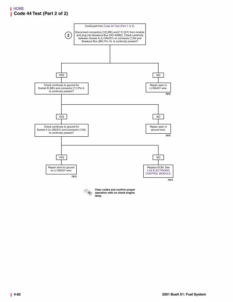
Code 44 Test (Part 2 of 2)
Continued from Code 44 Test (Part 1 of 2).
Disconnect connectors [10] (BK) and [11] (GY) from module and plug into Breakout Box (HD-42682). Check continuity
between Socket A (Lt GN/GY) on connector [134] and Breakout Box (BK) Pin 10. Is continuity present?
NO
Repair open inLt GN/GY wire.
YES
Check continuity to ground for Socket B (BK) and connector [11] Pin 8.
Is continuity present?
NO
Repair open inground wire.
YES
Check continuity to ground for Socket A (Lt GN/GY) and connector [134].
Is continuity present?
NO
Replace ECM. See 4.29 ELECTRONIC
CONTROL MODULE.
YES
Repair short to ground on Lt GN/GY wire.
Clear codes and confirm proper operation with no check engine lamp.
2
7975
7975
7974
7973
4-82 2001 Buell X1: Fuel System

HOME
TROUBLE CODES 52, 53, 54 AND 55 4.27
GENERAL
ECM FailureAll of the following codes indicate a failure which requiresreplacement of the ECM. See 4.29 ELECTRONIC CONTROLMODULE.
● Code 52 - RAM failure.
● Code 53 - ROM failure.
● Code 54 - EE PROM failure.
● Code 55 - Microprocessor failure.
NOTEDealership technicians filing warranty claims should use job/time code 7913 for all Code 52, 53, 54 and 55 ECM replace-ments.
2001 Buell X1: Fuel System 4-83
HOME
TROUBLE CODE 56 4.28
GENERAL
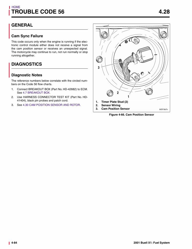
Cam Sync FailureThis code occurs only when the engine is running if the elec-tronic control module either does not receive a signal fromthe cam position sensor or receives an unexpected signal.The motorcycle may continue to run, not run normally or stoprunning altogether.
DIAGNOSTICS
Diagnostic NotesThe reference numbers below correlate with the circled num-bers on the Code 56 flow charts.
1. Connect BREAKOUT BOX (Part No. HD-42682) to ECM.See 4.7 BREAKOUT BOX.
2. Use HARNESS CONNECTOR TEST KIT (Part No. HD-41404), black pin probes and patch cord.
3. See 4.30 CAM POSITION SENSOR AND ROTOR.
Figure 4-66. Cam Position Sensor
11. Timer Plate Stud (2)2. Sensor Wiring3. Cam Position Sensor
2
3
b0313a7x
4-84 2001 Buell X1: Fuel System
HOME
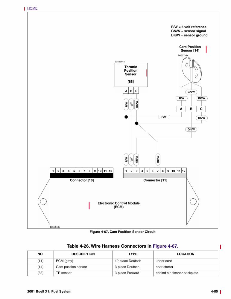
Figure 4-67. Cam Position Sensor Circuit
CBA
b0526x4x
Throttle Position Sensor
[88]
R/W V/Y
BK
/W
b0527x4x
R/W BK/W
GN/W
Cam PositionSensor [14]
R/W = 5 volt referenceGN/W = sensor signalBK/W = sensor ground
Electronic Control Module(ECM)
Connector [10] Connector [11]
A B C
R/W V/Y
GN
/W
BK
/W
BK/W
GN/W
R/W
Table 4-26. Wire Harness Connectors in Figure 4-67.
NO. DESCRIPTION TYPE LOCATION
[11] ECM (gray) 12-place Deutsch under seat
[14] Cam position sensor 3-place Deutsch near starter
[88] TP sensor 3-place Packard behind air cleaner backplate
2001 Buell X1: Fuel System 4-85
HOME
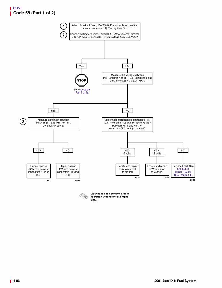
Code 56 (Part 1 of 2)
Attach Breakout Box (HD-42682). Disconnect cam position sensor connector [14]. Turn ignition ON.
Connect voltmeter across Terminal A (R/W wire) and Terminal C (BK/W wire) of connector [14]. Is voltage 4.75-5.25 VDC?
YES NO
Measure the voltage between Pin 1 and Pin 7 on [11] (GY) using Breakout
Box. Is voltage 4.75-5.25 VDC?
Go to Code 56 (Part 2 of 2).
YES NO
Measure continuity between Pin A on [14] and Pin 1 on [11].
Continuity present?
Disconnect harness side connector [11B] (GY) from Breakout Box. Measure voltage
between Pin 1 and Pin 7 of connector [11]. Voltage present?
NO.
Repair open in R/W wire between
connectors [11] and [14].
NO
Repair open inBK/W wire between connectors [11] and
[14].
YES. YES.12 volts
Locate and repairR/W wire short
to voltage.
Locate and repairR/W wire short
to ground.
YES. 5 volts.
STOP
Replace ECM. See 4.29 ELEC-
TRONIC CON-TROL MODULE.
1
2
2
7945 79457970 7955
7965
Clear codes and confirm proper operation with no check engine lamp.
4-86 2001 Buell X1: Fuel System
HOME
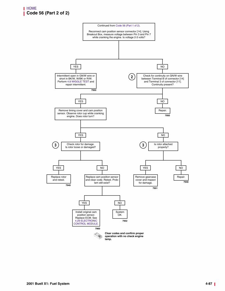
Code 56 (Part 2 of 2)
Continued from Code 56 (Part 1 of 2).
Reconnect cam position sensor connector [14]. Using Breakout Box, measure voltage between Pin 3 and Pin 7
while cranking the engine. Is voltage 2-3 volts?
YES NO
Check for continuity on GN/W wire between Terminal B of connector [14]
and Terminal 3 of connector [11].Continuity present?
Intermittent open in GN/W wire or short in BK/W, W/BK or R/W.
Perform 4.8 WIGGLE TEST and repair intermittent.
YES NO
Repair.Remove timing cover and cam position sensor. Observe rotor cup while cranking
engine. Does rotor turn?
YES
Check rotor for damage. Is rotor loose or damaged?
NO
Is rotor attached properly?
YES
Remove gearcase cover and inspect
for damage.
NO
Repair.
YES
Replace rotorand retest.
NO
Replace cam position sensor and clear code. Retest. Prob-
lem still exist?
Clear codes and confirm proper operation with no check engine lamp.
7950
7950
YES
Install original cam position sensor.
Replace ECM. See 4.29 ELECTRONIC
CONTROL MODULE.
NO
System OK.
7940
7960
7952
7951
7940
2
3 3
2001 Buell X1: Fuel System 4-87