Trooper Scale Instruction Manual - Test Equipment Depot
40
Trooper Scale Instruction Manual 99 Washington Street Melrose, MA 02176 Phone 781-665-1400 Toll Free 1-800-517-8431 Visit us at www.TestEquipmentDepot.com
Transcript of Trooper Scale Instruction Manual - Test Equipment Depot

Trooper ScaleInstruction Manual
99 Washington Street Melrose, MA 02176 Phone 781-665-1400Toll Free 1-800-517-8431
Visit us at www.TestEquipmentDepot.com


Ohaus Corporation, 19A Chapin Road, P.O. Box 2033 Pine Brook, New Jersey, 07058, USA
Declaration of Conformity We, Ohaus Corporation, declare under our sole responsibility that the balance models listed below marked with“CE” - are in conformity with the directives and standards mentioned.Declaración de Conformidad Nosotros, Ohaus Corporation, declaramos bajo responsabilidad exclusiva que los modelos de balanzasindicados a continuación - con el distintivo ,CE’ - están conformes con las directivas y normas citadas.Déclaration de conformité Nous, Ohaus Corporation, déclarons sous notre seule responsabilité, que les types de balance ci-dessous cité- munis de la mention «CE» - sont conformes aux directives et aux normes mentionnées ci-après.
Models/Type Trooper SeriesModelo/Tipo Trooper SeriesModèle/Type Trooper Series
EC Marking: EC Directive Applicable StandardsMarcado EC Directive EC Normas aplicablesMarquage CE Directive CE Normes applicable
73/23/EEC EN60950-1:2001Low VoltageBaja tensiónBasse tension
89/336/EEC EN61326:1997+A1:1998+A2:2001+A3:2003Electromagnetic compatibilityCompatibilidad electromagnéticaCompatibilité électromagnétique
1) Applies only to certified non-automatic weighing instruments Aplicable solamente a instrumentos de pesaje aprobados de funcionamiento no automático S’applique uniquement aux instruments de pesage à fonctionnement non automatique approuvés
Ted XiaPresident
Ohaus CorporationPine Brook, NJ USA
Jean-Yves CheverGeneral Manager
Ohaus EuropeGreifensee, Switzerland
Date CE mark first applied: March 2002
0103M
90/384/EEC EN45501:1992 1)
Non Automatic Weighing InstrumentsPara balanzas no automátäcasBalances à fonctionnement non automatique
For non-automatic weighing instruments used in an Article 1, 2.(a) application, additional metrological marking according to AnnexIV of Council directive 90/384/EEC must be attached to the instrumentPara instrumentos de pesaje no automático usados en una aplicación descrita en el Artículo 1, 2.(a), se debe colocar sobre elinstrumento una marcación metrológica adicional de acuerdo con el Anexo IV de la Directriz del Consejo 90/384/EEC.Pour les instruments de pesage non-automatiques utilisés dans une application Article 1, 2.(a), un repérage métrologiqueadditionnel conforme à l’Annexe IV de la Directive 90/384/EEC du Conseil doit être présent sur l’instrument.
year

Important notice for verified weighing instrumentsWeighing Instruments verified at the place of manufacture bear one of the preceding mark on the packing label andthe green ‘M’ (metrology) sticker on the descriptive plate. They may be put into service immediately.
Weighing Instruments to be verified in two stages have no green ‘M’ (metrology) on the descriptive plate and bear oneof the preceding identification mark on the packing label. The second stage of the initial verification must be carriedout by the approved service organization of the authorized representative within the EC or by the national weight &measures (W+M) authorities.
The first stage of the initial verification has been carried out at the manufacturers work. It comprises all tests according to the adoptedEuropean standard EN 45501:1992, paragraph 8.2.2.
If national regulations limit the validity period of the verification, the user of the weighing instrument must strictly observe the re-verificationperiod and informthe respective W+M authorities.
Notificación importante para instrumentos de pesaje verificadosLos instrumentos de pesaje verificados en el sitio de fabricación llevan una de las marcas precedentes en el rótulo delempaque y la etiqueta de la ‘M’ verde (metrología) en la placa descriptiva. Estos instrumentos se pueden poner enfuncionamiento inmediatamente.
Los instrumentos de pesaje a ser verificados en dos etapas no tienen ninguna ‘M’ verde (metrología) en la placadescriptiva, y presentan una de las marcas de identificación precedentes sobre el rótulo del empaque. La segundaetapa de la verificación inicial debe ser llevada a cabo por la organización de servicio aprobada del representanteautorizado dentro de la CE o por las autoridades nacionales de pesos y medidas.
La primera etapa de la verificación inicial ha sido llevada a cabo en el sitio de fabricación. Ésta comprende todas las pruebasestipuladas por el estándar europeo adoptado: EN 45501:1992, párrafo 8.2.2.
Si las normas nacionales limitan el periodo de validez de la verificación, el usuario del instrumento de pesaje debe seguir estrictamenteel periodo de re-verificación e informar a las correspondientes autoridades de pesos y medidas.
Avis important pour les instruments de pesage vérifiésLes instruments de pesage vérifiés sur le site de fabrication portent l’une des marques précédentes sur l’étiquette del’emballage avec un autocollant M (pour Métrologie) en vert sur la plaque descriptive. Ces instruments peuvent êtreimmédiatement mis en service.
Les instruments de pesage à vérifier en deux étapes ne portent pas d’autocollant M (pour Métrologie) en vert sur laplaque descriptive et portent l’une des marques d’identification précédentes sur l’étiquette de l’emballage. La deuxièmeétape de la vérification initiale doit être exécutée par l’organisation de service homologuée du représentant agréé ausein de la CE ou par les autorités nationales de poids et mesures.
La première étape de la vérification initiale a été exécutée sur le site du fabricant. Elle se compose des tests requis par la normeeuropéenne EN45501:1992, paragraphe 8.2.2.
Si des règlements nationaux limitent la durée de validité de la vérification, il incombe à l’utilisateur dudit instrument de pesage derespecter strictement la période de re-vérification et d’informer les autorités de poids et mesures respectives.

DisposalIn conformance with the European Directive 2002/96 EC on Waste Electrical and Electronic Equipment (WEEE) thisdevice may not be disposed of in domestic waste. This also applies to countries outside the EU, per their specificrequirements.
Please dispose of this product in accordance with local regulations at the collecting point specified for electrical andelectronic equipment.
If you have any questions, please contact the responsible authority or the distributor from which you purchased thisdevice.
Should this device be passed on to other parties (for private or professional use), the content of this regulationmust also be related.
Thank you for your contribution to environmental protection.
Eliminación de residuosDe conformidad con las exigencias de la directiva europea 2002/96 CE sobre residuos de aparatos eléctricos yelectrónicos (RAEE), este equipo no puede eliminarse como basura doméstica. Esta prohibición es asimismoválida para los países que no pertenecen a la UE cuyas normativas nacionales en vigor así lo reflejan.
Elimine este producto, según las disposiciones locales, mediante el sistema de recogida selectiva de aparatoseléctricos y electrónicos.
Si tiene alguna pregunta al respecto, diríjase a las autoridades responsables o al distribuidor que le proporcionó elequipo.
Si transfiere este equipo (por ejemplo, para la continuación de su uso con fines privados, comerciales oindustriales), deberá transferir con él esta disposición.
Muchas gracias por su contribución a la conservación medioambiental.
EliminationEn conformité avec les exigences de la directive européenne 2002/96 CE relative aux déchets d'équipementsélectriques et électroniques (DEEE), cet appareil ne doit pas être éliminé avec les déchets ménagers. Logiquement,ceci est aussi valable pour les pays en dehors de l'UE conformément aux règlementations nationales en vigueur.
Veuillez éliminer cet appareil conformément aux prescriptions locales dans un conteneur séparé pour appareilsélectriques et électroniques.
Pour toute question, adressez-vous aux autorités compétentes ou au revendeur chez qui vous avez acheté cetappareil.
En cas de remise de cet appareil (p. ex. pour une utilisation privée ou artisanale/industrielle), cette prescription doitêtre transmise en substance.
Merci pour votre contribution à la protection de l'environnement.

ISO 9001 RegistrationIn 1994, Ohaus Corporation, USA, was awarded a certificate of registration to ISO 9001 by Bureau Veritus Quality International (BVQI),confirming that the Ohaus quality management system is compliant with the ISO 9001 standard’s requirements. On May 15, 2003, OhausCorporation, USA, was re-registered to the ISO 9001:2000 standard.
Registro ISO 9001En 1994, Bureau Veritus Quality International (BVQI) le otorgó a Ohaus Corporation, EE.UU., un certificado de registro ISO 9001 el cualconfirma que el sistema administrativo de calidad de Ohaus cumple con los requerimientos del estándar ISO 9001. En mayo 15 del 2003,Ohaus Corporation, EE.UU., fue registrada nuevamente al estándar ISO 9001:2000.
Enregistrement ISO 9001En 1994, le Bureau Veritus Quality International (BVQI) a octroyé la certification d’enregistrement ISO 9001 à Ohaus Corporation, États-Unisd’Amérique, confirmant que le système de gestion de la qualité Ohaus était conforme aux conditions normalisées de l’ISO 9001. Le 15 mai2003, Ohaus Corporation, États-Unis d’Amérique, a été ré-enregistrée à la norme ISO 9001:2000.
FCC NoteThis equipment has been tested and found to comply with the limits for a Class A digital device, pursuant to Part 15 of the FCC Rules. Theselimits are designed to provide reasonable protection against harmful interference in a residential installation. This equipment generates, usesand can radiate radio frequency energy and, if not installed and used in accordance with the instructions, may cause harmful interference toradio communications. However, there is no guarantee that interference will not occur in a particular installation. If this equipment doescause harmful interference to radio or television reception, which can be determined by turning the equipment off and on, the user isencouraged to try to correct the interference by one or more of the following measures:
• Reorient or relocate the receiving antenna.• Increase the separation between the equipment and receiver.• Connect the equipment into an outlet on a circuit different from that to which the receiver is connected.• Consult the dealer or an experienced radio/TV technician for help.
Industry Canada NoteThis Class B digital apparatus complies with the Canadian ICES-003.Cet appareil numérique de la classe B est conforme à la norme NMB-003 du Canada.

EN-1Trooper ScaleTrooper ScaleTrooper ScaleTrooper ScaleTrooper Scale
TABLE OF CONTENTS
OVERVIEW OF CONTROLS AND DISPLAY FUNCTIONS ............................................................................ EN-3
1. GETTING TO KNOW YOUR TROOPER SCALE .......................................................................................... EN-4
1.1 Introduction ....................................................................................................................................... EN-4
1.1.1 Features .................................................................................................................................. EN-4
2. INSTALLATION ................................................................................................................................... EN-5
2.1 Unpacking and Checking ..................................................................................................................... EN-5
2.2 Selecting the Location ......................................................................................................................... EN-5
2.3 Connecting Power .............................................................................................................................. EN-5
2.3.1 Battery Installation ..................................................................................................................... EN-5
2.3.2 AC Power ................................................................................................................................. EN-5
2.3.3 Leveling the Scale ...................................................................................................................... EN-6
2.3.4 Stabilization .............................................................................................................................. EN-6
3. OPERATION ....................................................................................................................................... EN-6
3.1 Turning On Scale ................................................................................................................................ EN-7
3.2 Turning Off Scale ................................................................................................................................ EN-7
3.3 Zero Operation ................................................................................................................................... EN-7
3.4 Tare Operation ................................................................................................................................... EN-7
3.5 Gross/Net/Tare Recall Operation ........................................................................................................... EN-8
3.6 Unit Switch Operation .......................................................................................................................... EN-8
3.7 RS232 Commands ............................................................................................................................ EN-9
3.7.1 Output Formats ........................................................................................................................ EN-9
3.8 Printing Data ..................................................................................................................................... EN-9
3.8.1 RS-232 Pin Out ........................................................................................................................ EN-9
4. SETUP ............................................................................................................................................. EN-10
4.1 Setup Protection ............................................................................................................................... EN-10
4.4.1 Control Functions ................................................................................................................... EN-10
4.4.2 Menu Structure ....................................................................................................................... EN-11
4.4.3 Setup Menu ........................................................................................................................... EN-12
4.4.4 Readout Menu........................................................................................................................ EN-14
4.4.5 Print Menu ............................................................................................................................. EN-18
4.4.6 Lockout Switch Menu .............................................................................................................. EN-20

EN-2 Trooper ScaleTrooper ScaleTrooper ScaleTrooper ScaleTrooper Scale
TABLE OF CONTENTS (Cont.)5. CALIBRATION AND SEALING ............................................................................................................. EN-22
5.1 Legal for Trade (LFT) Operation and LFT Sealing ................................................................................... EN-29
6. CARE AND MAINTENANCE ................................................................................................................ EN-30
6.1 Troubleshooting ............................................................................................................................... EN-30
6.2 Error Codes List ................................................................................................................................ EN-32
6.3 Service Information ........................................................................................................................... EN-32
6.4 Accessories ..................................................................................................................................... EN-32
6.5 Technical Data ................................................................................................................................. EN-32
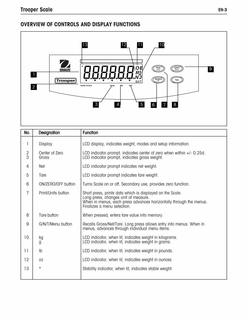
EN-3Trooper Scale
No. Designation No. Designation No. Designation No. Designation No. Designation FunctionFunctionFunctionFunctionFunction
1 Display LCD display, indicates weight, modes and setup information.
2 Center of Zero LCD indicator prompt, indicates center of zero when within +/- 0.25d. 3 Gross LCD indicator prompt, indicates gross weight.
4 Net LCD indicator prompt indicates net weight.
5 Tare LCD indicator prompt indicates tare weight.
6 ON/ZERO/OFF button Turns Scale on or off. Secondary use, provides zero function.
7 Print/Units button Short press, prints data which is displayed on the Scale.Long press, changes unit of measure.When in menus, each press advances horizontally through the menus.Finalizes a menu selection.
8 Tare button When pressed, enters tare value into memory.
9 G/N/T/Menu button Recalls Gross/Net/Tare. Long press allows entry into menus. When inmenus, advances through individual menu items.
10 kg LCD indicator, when lit, indicates weight in kilograms.g LCD indicator, when lit, indicates weight in grams.
11 lb LCD indicator, when lit, indicates weight in pounds.
12 oz LCD indicator, when lit, indicates weight in ounces.
13 * Stability indicator, when lit, indicates stable weight.
OVERVIEW OF CONTROLS AND DISPLAY FUNCTIONS
OE
NJR]BAT
*
1
2
3 4 5 6 8
9
10
7
1113 12
EN-4 Trooper Scale
1. GETTING TO KNOW YOUR TROOPER SCALE
1.1 IntroductionThank you for deciding to purchase a Trooper Scale from Ohaus. The Ohaus Trooper Scale is a rugged, reliable,electronic scale designed for easy operation.
The Trooper Scale operates from AC power and can also be powered by six Alkaline “C” batteries internally. A six digitLCD display is 1.0 inches/2.5 centimeters in height provides easy visibility when working at distances from the Scale.Four buttons mounted on the front panel enable simple set up procedures. A menu lockout switch can be set to lock outvarious functions of the Scale to prevent settings from being changed. An RS232 Interface is built in.
Behind your instrument stands OHAUS, a leading manufacturer of precision Indicators, Scales and Balances. An After-market Department with trained instrument technicians is dedicated to providing you with the fastest service possible inthe event your instrument requires servicing. OHAUS also has a Customer Service Department to answer any inquiriesregarding applications and accessories.
To ensure you make full use of the possibilities offered by your Trooper Scale, please read the manual completely beforeinstallation and operation.
1.1.1 FeaturesMajor features include:
• 6 digits, 7-segments, 25 mm Numeric LCD display
• Durable ABS housing
• 4 membrane switches
• Push-button Tare/Clear
• Flexible unit switching-lb/kg/oz/g
• Enhanced digital filtering
• Overload/Underzero display indication
• RS232 Serial Communication in Ohaus RS-Interface
• Up to 100 hours continuous battery operation
• AC & DC power supply
• Low - BAT warning comes on 20 minutes prior to low power point
• Auto shut off for power saving

EN-5Trooper Scale
2.2 Selecting the LocationThe Scale should be used in an environment which is free from corrosives, vibration or temperature extremes. Thesefactors will affect displayed weight readings. The Scale should be located on a stable level surface and kept away fromvibrating sources such as large machinery. Maximum accuracy will be achieved when the area is clean and vibrationfree.
2. INSTALLATION
2.1 Unpacking and CheckingOpen the package and remove the instrument and the accessories. Check the completeness of the delivery. The follow-ing accessories are part of the standard equipment of your new Scale.
Remove packing material from the instrument.
Check the instrument for transport damage. Immediately inform your Ohaus dealer if you have complaints or parts aremissing. Your Trooper Scale package should contain:
• Trooper Scale• Warranty card• AC power adapter• Instruction Manual• Lead seal for weights and measures sealing
Store all parts of the packaging. This packaging guarantees the best possible protection for the transport of yourinstrument.NOTE: Remove the two shipping screws if present on top of the unit.
2.3 Connecting Power
2.3.1 Battery InstallationRemove battery cover and insert 6 Alkaline C-type batteries into the battery holder making sure that the batteries areproperly orientated (correct polarity).
NOTE: It is recommended that when the Trooper Scale is operated from batteries, the Auto-Off Timer feature be turnedon to extend battery life. When setting up the Scale, refer to Intial Setup, Readout menu, paragraph 4.4.4.
2.3.2 AC PowerConnect the AC power cord from the Scale and plug into a convenient power outlet.
NOTICE: The socket/outlet must be installed near
the equipment and shall be easily accessible.

EN-6 Trooper Scale
2.3.3 Leveling the ScaleExact horizontal positioning and stable installation are prerequisites for repeatable results. To compensate smallirregularities or inclinations at the location, the instrument can be leveled.
For exact horizontal positioning, the Scale is equipped with a level indicator located at the rear.
Adjust the leveling feet until the air bubble in the indicator is centered.
NOTE: The instrument should be leveled each time its location is changed.
2.3.4 StabilizationBefore initially using the Scale, allow time for it to adjust to its new environment. Recommended warm up period isfive (5) minutes.
3. OPERATIONThe Trooper Scale has been factory calibrated and is ready for operation. You can operate the scale at this point usingthe factory default settings. You can check the default menu settings on page 11. All bolded items on the menu are thefactory default settings. The scale will operate in the default mode. If you want to change the settings, continue withSection 4, Setup.
When the Scale is positioned for operation, follow the operational procedure outlined next.
2. INSTALLATION (Cont.)

EN-7Trooper Scale
3. OPERATION (Cont.)
3.4 Tare OperationWhen weighing material or objects that must be held in acontainer, taring stores the container weight in the Indicator’smemory. To store the container weight, proceed as fol-lows:
Place the container on the scale. Sample shown is 2kg.
Press TARE button. Scale is tared andshows Netweight.
3.1 Turning On ScalePress and hold ON/ZERO/OFF button until the LCD dis-play appears, then release ON/ZERO/OFF button. Thedisplay momentarily displays segment check, the soft-ware revision of the Scale and then goes into a weighingmode.
3.2 Turning Off ScaleTo turn the Scale off, press the ON/ZERO/OFF button untilOFF is displayed.
3.3 Zero OperationUsing a shortshortshortshortshort duration press, press ON/ZERO/OFF but-ton to zero the Scale. The display acknowledges by indi-cating the selected measuring unit followed by a zeroeddisplay.
NOTE: Stable cursor must be lit to accept zero operation.
Place item to be weighed on the scale platform. The dis-play indicates a sample of 5kg, gross weight.
Gross
Net
*
Centerof Zero
Gross
*
*
Gross
Gross
Centerof Zero
*
Centerof Zero
*

EN-8 Trooper Scale
3. OPERATION (Cont.)
3.5 Gross/Net/Tare Recall Operation
When a container has been placed on the platform andtared, it's weight is stored in memory. Adding material tothe container is shown as NET weight. The gross weight isa combination of the tared weight and the material. The G/N/T/MENU button allows switching between GROSS, NETand TARE weights.
Repeatedly press (short presses) the G/N/T/MENU but-ton to cycle through Gross, Tare and Net readings. Thesample illustrations indicate a tare weight of 2kg simu-lating a container, a net weight of 8kg which would bethe material in a container and a gross weight of 10kgwhich is the total weight of the container and material.After 3 seconds, display returns to Net weight.
Tare
3.6 Unit Switch OperationTo switch measuring units, proceed as follows:
Press and hold PRINT/UNITS button until displaychanges to selected measuring unit. Depending on whichunits are enabled in the menu, you have a choice of g,lb, kg or oz. The display sample indicates 8kg loadchanged to lbs shown as a net weight because a taredweight of 2kg was used and stored in memory.
Gross
Net
*
*
*
Net
Net
*
*

EN-9Trooper Scale
NOTE: If you hold this button down too long, the displaywill advance to another measuring unit.
3.8.1 RS-232 Pin Out.The table illustrates the pin-out connections on the RS-232 connector.
3.7 RS232 CommandsAll communication is accomplished using standard ASCII format. Characters shown in the following table are acknowl-edged by the Scale. Invalid command response "ES" error indicates the Scale has not recognized the command.Commands sent to the Scale must be terminated with a carriage return (CR) or carriage return-line feed (CRLF). Dataoutput by the Scale is always terminated with a carriage return-line feed (CRLF).
3.7.1 Output Formats
CommandCharacter Description? Print current mode: kg, g, lb., oz.P Same as pressing PRINT button.T Same as pressing TARE button.Z Same as pressing ZERO button.xS Print Stable only. Where x=0 Off, and x=1 OnAS Automatically send data when stable after motion.xxxxS Send at interval. Where xxxx=1 to 3600 seconds.CS Send as fast as possible (continuous print)M Increment to next enabled unit
To turn auto printing, interval printing or continuous printing off, send P to reset normal printing mode.
RS232 USER COMMAND TABLE
3. OPERATION (Cont.)
1 N/C2 Data In (RXD)3 Data Out (TXD)4 N/C5 Ground6, 7, 8, 9 N/C
3.8 Printing DataPrinting data to an external computer or printer requires that the communications parameters in the Print menu, be setfirst. Refer to paragraph 4.4.5 Print Menu for proper set up.
To print data, press PRINT/UNITS button with a short press. The display acknowledges by momentarily blinking off.
Data output can be initiated in one of two ways:1. By pressing the PRINT/Units button, or 2. Sending a print command (“P”) from a computer.
Output FormatsThe output format is as follows:
Weight* Spaces Unit Stable Legend CR LFLength: 9 1 3 1 1 1 1
blank=stable G,N,T "?"= not stable
* Displayed weight sent right justified with lead zero blanking. Nine characters (fixed) include: decimal point (1), weight (7 max), polarity (1) : blank if positive, floating negative (1)

EN-10 Trooper Scale
4. SETUPFor first time setup, step through all menus and set the parameters as desired.
4.1 Setup ProtectionThe Trooper Scale is equipped with menus which permit certain functions to be locked out (not changed) duringoperation. If you intend to lock out changes to the setup selections you make, you will need to access the Lock Switchlocated on the main PC circuit board following the setup procedure.
The Scale has five menus; CAL, SETUP, READ, PRINT and LOCSW which are entered by pressing and holding the G/N/T/MENU button until MENU is displayed, then releasing it. The display then switches to SETUP. To access the rest of themenus, the PRINT/UNITS button is repeatedly pressed until the desired menu is reached.
4.4.1 Control FunctionsDuring setup, only the PRINT/UNITS and G/N/T/MENU buttons are used.
PRINT/UNITS ButtonChange between menus horizontally or change sub-menu parameters.
G/N/T/MENU ButtonPress and hold to enter menu. Enters menu and steps through sub-menus vertically.
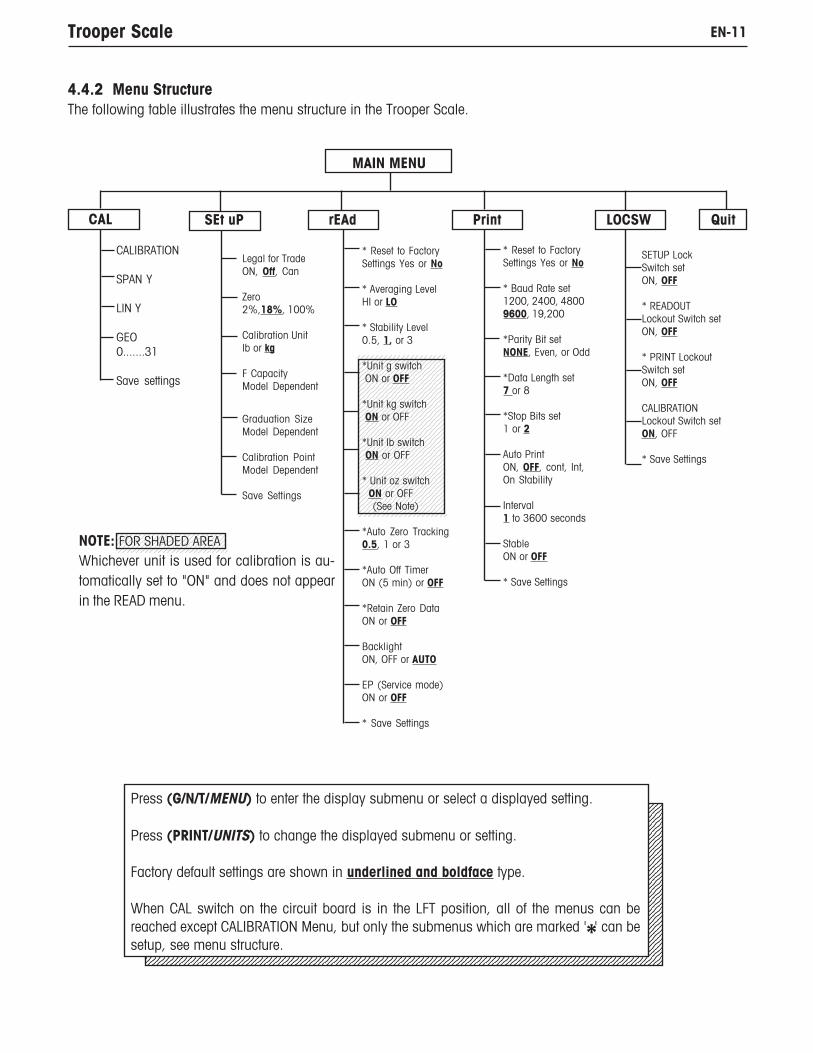
EN-11Trooper Scale
MAIN MENU
CAL SEt uP rEAd Print LOCSW
CALIBRATION
SPAN Y
LIN Y
GEO0.......31
Save settings
Legal for TradeON, Off, Can
Zero2%,18%, 100%
Calibration Unitlb or kg
F CapacityModel Dependent
Graduation SizeModel Dependent
Calibration PointModel Dependent
Save Settings
* Reset to FactorySettings Yes or No
* Averaging LevelHI or LO
* Stability Level0.5, 1, or 3
*Unit g switch ON or OFF
*Unit kg switch ON or OFF
*Unit lb switch ON or OFF
* Unit oz switch ON or OFF (See Note)
*Auto Zero Tracking0.5, 1 or 3
*Auto Off TimerON (5 min) or OFF
*Retain Zero DataON or OFF
BacklightON, OFF or AUTO
EP (Service mode)ON or OFF
* Save Settings
* Reset to FactorySettings Yes or No
* Baud Rate set1200, 2400, 48009600, 19,200
*Parity Bit setNONE, Even, or Odd
*Data Length set7 or 8
*Stop Bits set1 or 2
Auto PrintON, OFF, cont, Int,On Stability
Interval1 to 3600 seconds
StableON or OFF
* Save Settings
SETUP LockSwitch setON, OFF
* READOUTLockout Switch setON, OFF
* PRINT LockoutSwitch setON, OFF
CALIBRATIONLockout Switch setON, OFF
* Save Settings
Press (G/N/T/MENU) to enter the display submenu or select a displayed setting.
Press (PRINT/UNITS) to change the displayed submenu or setting.
Factory default settings are shown in underlined and boldface type.
When CAL switch on the circuit board is in the LFT position, all of the menus can bereached except CALIBRATION Menu, but only the submenus which are marked ' ' can besetup, see menu structure.
Quit
NOTE: FOR SHADED AREA
Whichever unit is used for calibration is au-tomatically set to "ON" and does not appearin the READ menu.
4.4.2 Menu StructureThe following table illustrates the menu structure in the Trooper Scale.
*

EN-12 Trooper Scale
4.4.3 Setup MenuThe Setup Menu is used to set up the Scale for the first time.
ProcedureWith the Scale ON, press and hold the G/N/T/MENUbutton until MENU is displayed. When you release G/N/T/MENU button, SETUP is displayed when the CALIBRA-TION Lock Switch (software) is in the locked position.When the CALIBRATION Lock Switch is locked, the Scalewill not permit calibration.
Press PRINT/UNITS button, SETuP is displayed.
Press G/N/T/MENU button, LFTOFF is displayed. Legalfor trade selections are:
'LFT ON' - LFT is ON'LFTOFF' - LFT is OFF'LFTCAn' - LFT is set for Canada
Press PRINT/UNITS button and select either ON, OFF orCanada.
Press G/N/T/MENU button, 0 18 is displayed. This istheZero 2%, 18% or 100% setting. 2% - zero operationrange is - 2% to + 2%. 18% - zero operating range is -2% to +18%, 100% - zero operation range is -2% to+100%.NOTE: : : : : If LFT is ON, only 2% and 18% are available.
Press PRINT/UNITS button, and select either 2%, 18%or 100%.
Press G/N/T/MENU button, CAL Un kg is displayed.This is the calibration unit setting. Selections are:
'lb' - calibration unit is lb'kg' - calibration unit is kg.
Press PRINT/UNITS button, and select either kg or lb.
NOTE: The Scale is factory calibrated. After changingthe calibration unit, the Scale must be recalibratedbefoe using!
kg

EN-13Trooper Scale
Press G/N/T/MENU button, Gd 0.1 is displayed. This isthe graduation size. For available selections, press PRINT/UNITS button until desired graduation value is reached.
Press G/N/T/MENU button, CP 30 kg is displayed. Thisis the full scale calibration point setting. Default is ap-proximately 2/3 full scale capacity and can be selecteddepending upon the model.
Press PRINT/UNITS button until desired calibration valueis reached.
Press G/N/T/MENU button to end this block, SAVE isdisplayed.
Press G/N/T/MENU button, rEAD is displayed which isthe next menu or press PRINT/UNITS button to return toSetup menu.
4.4.3 Setup Menu (Cont.)
kg
kg

EN-14 Trooper Scale
4.4.4 Readout MenuThe Readout menu is used to adapt the Scale to environmental conditions, set measuring units on/off, auto zerotracking, timer on/off, retain zero data and backlighting. Review all of the settings available before proceeding.
ProcedureTo select any of the items in the Readout menu, proceedas follows: NOTE: If you have entered from the preceedingmenu, disregard the first step.
With the Scale ON, press and hold the G/N/T/MENU but-ton until MENU is displayed. When you releasethe G/N/T/MENU button, CAL is displayed, then press PRINT/UNITS button, until rEAd is displayed.
Press G/N/T/MENU button, rESETn is displayed. This al-lows resetting the readout menu to factory defaults.rESETn = no and does not reset settings. rESETy= yesand will reset the entire readout menu as follows: AL Lo,StAb 1, Un Off g, Un On kg, Un On lb, Un Off oz, AZt 0.5,Aot Off, rZd Off and Backlight Off.
Press PRINT/UNITS button,and select N or Y.
AVERAGING LEVELAveraging level compensates for vibration or excessive aircurrents on the scale platform. During operation, the Scalecontinually takes weight readings from the load cell. Suc-cessive readings are then digitally processed to achieve astabilized display. Using this feature, you specify how muchprocessing you need.
HI and LO settings are available.HI setting:More processing, greater stability andslower stabilization time.
LO setting:Less processing, less stability and fasterstabilization time.
EN-15Trooper Scale
4.4.4 Readout Menu (Cont.)
ProcedureAVERAGING LEVEL (Cont.)
Press G/N/T/MENU button, AL LO is displayed. This isaveraging level settings. Selections are:
'Lo' - Averaging level is low'Hi' - Averaging level is high.
Press PRINT/UNITS button,and select LO or HI.
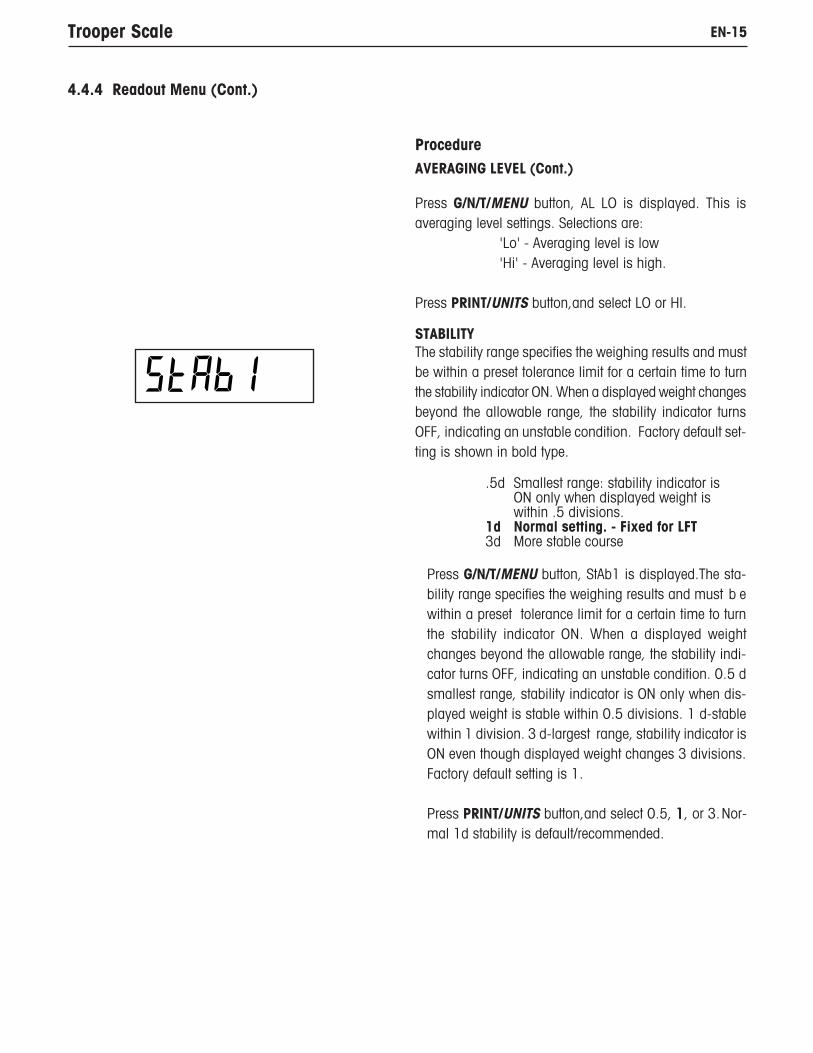
STABILITYThe stability range specifies the weighing results and mustbe within a preset tolerance limit for a certain time to turnthe stability indicator ON. When a displayed weight changesbeyond the allowable range, the stability indicator turnsOFF, indicating an unstable condition. Factory default set-ting is shown in bold type.
.5d Smallest range: stability indicator isON only when displayed weight iswithin .5 divisions.
1d Normal setting. - Fixed for LFT3d More stable course
Press G/N/T/MENU button, StAb1 is displayed.The sta-bility range specifies the weighing results and must b ewithin a preset tolerance limit for a certain time to turnthe stability indicator ON. When a displayed weightchanges beyond the allowable range, the stability indi-cator turns OFF, indicating an unstable condition. 0.5 dsmallest range, stability indicator is ON only when dis-played weight is stable within 0.5 divisions. 1 d-stablewithin 1 division. 3 d-largest range, stability indicator isON even though displayed weight changes 3 divisions.Factory default setting is 1.
Press PRINT/UNITS button,and select 0.5, 11111, or 3.Nor-mal 1d stability is default/recommended.
EN-16 Trooper Scale
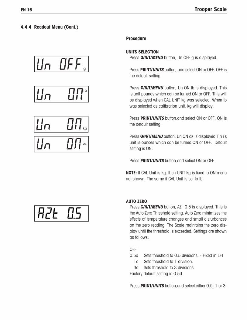
UNITS SELECTIONPress G/N/T/MENU button, Un OFF g is displayed.
Press PRINT/UNITS button, and select ON or OFF. OFF isthe default setting.
Press G/N/T/MENU button, Un ON lb is displayed. Thisis unit pounds which can be turned ON or OFF. This willbe displayed when CAL UNIT kg was selected. When lbwas selected as calibration unit, kg will display.
Press PRINT/UNITS button,and select ON or OFF. ON isthe default setting.
Press G/N/T/MENU button, Un ON oz is displayed.T h i sunit is ounces which can be turned ON or OFF. Defaultsetting is ON.
Press PRINT/UNITS button,and select ON or OFF.
NOTE: If CAL Unit is kg, then UNIT kg is fixed to ON menunot shown. The same if CAL Unit is set to lb.
4.4.4 Readout Menu (Cont.)
Procedure
AUTO ZEROPress G/N/T/MENU button, AZt 0.5 is displayed. This isthe Auto Zero Threshold setting. Auto Zero minimizes theeffects of temperature changes and small disturbanceson the zero reading. The Scale maintains the zero dis-play until the threshold is exceeded. Settings are shownas follows:
OFF0.5d Sets threshold to 0.5 divisions. - Fixed in LFT
1d Sets threshold to 1 division. 3d Sets threshold to 3 divisions.
Factory default setting is 0.5d.
Press PRINT/UNITS button,and select either 0.5, 1 or 3.

EN-17Trooper Scale
AUTO POWER OFFPress G/N/T/MENU button, AOtOFF is displayed. This isthe Auto Off Timer. When set ON, the Scale will shut offautomatically after 5 minutes has elapsed based on thecondition that no button is pressed and the scale plat-form is stable during that period.
Press G/N/T/MENU button,and select ON or OFF.OFF is the default setting.
RETAIN ZERO DATAPress G/N/T/MENU button, Un rZdOFFis displayed. Thisis Retain Zero Data which can be turned on or off.When set On, the Scale stores the current zero point andrestores it on the power-up.
Press PRINT/UNITS button, and select ON or OFF. OFF isthe default setting.
4.4.4 Readout Menu (Cont.)
LCD BACK LIGHTPress G/N/T/MENU button, bLAutOis displayed. You canselect to have the LCD backlight either on contiuously,off or in an automatic mode which turns off the displayin 5 seconds.
Press PRINT/UNITS button, and either select ON, OFF orAuto. Auto is the default setting.
EPThis is service function and is not a user operated com-mand. OFF is the default setting.
SAVEPress G/N/T/MENU button to end this block, SAVE is dis-played. All settings are retained.
Press G/N/T/MENU button, setting are saved and PRINTis displayed which is the next menu or press PRINT/UNITS button to go back to Setup menu without saving.
NOTE: (If initial setup, go to the next paragraph. To exitfrom the Setup, press PRINT/UNITS button to skip toPRINT then to LOCKSW, then QUIT. Press G/N/T/MENUbutton to go back to the weighing mode).

EN-18 Trooper Scale
4.4.5 Print Menu
The Print menu provides data communication settings which can be entered. It contains 9 submenus: Reset, Baud rate,Parity Bit, Data Length, Stop Bits, Auto Print, Interval, Stable and Save.
Procedure
PRINTTo select any of the items in the Print menu, proceed asfollows: NOTE: If you have entered from the preceedingmenu, disregard the first step.
With the Scale ON, press and hold the G/N/T/MENU but-ton until MENU is displayed. When you release the G/N/T/MENU button, CAL is displayed, then press PRINT/UNITS button, until Print is displayed.
RESETPress G/N/T/MENU button, rESEtn is displayed. Thisal-lows resetting the Print menu to factory defaults.rESETn = no does not reset settings. rESETy = yes willreset the entire Print menu as follows:Baud rate =2400, parity =none, data length=7,stop bit=2.
Press PRINT/UNITS button, and select N or Y.
BAUD RATEPress G/N/T/MENU button, bd9600 is displayed.
Press PRINT/UNITS button, and select desired baudrate. Baud rate selections are: 1200, 2400, 4800 9600and 19200. 9600 is the default setting.
PARITYPress G/N/T/MENU button, PAr NO is displayed. This isthe parity bit.
Press PRINT/UNITS button, and select desired parity ofNO=none, Odd=odd, E=even. Default setting is none.
EN-19Trooper Scale
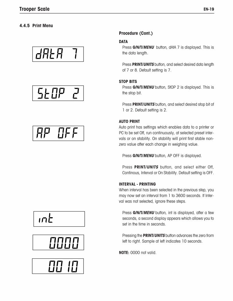
DATAPress G/N/T/MENU button, dAtA 7 is displayed. This isthe data length.
Press PRINT/UNITS button, and select desired data lengthof 7 or 8. Default setting is 7.
STOP BITSPress G/N/T/MENU button, StOP 2 is displayed. This isthe stop bit.
Press PRINT/UNITS button, and select desired stop bit of1 or 2. Default setting is 2.
AUTO PRINTAuto print has settings which enables data to a printer orPC to be set Off, run continuously, at selected preset inter-vals or on stability. On stability will print first stable non-zero value after each change in weighing value.
Press G/N/T/MENU button, AP OFF is displayed.
Press PRINT/UNITS button, and select either Off,Continous, Interval or On Stability. Default setting is OFF.
INTERVAL - PRINTINGWhen interval has been selected in the previous step, youmay now set an interval from 1 to 3600 seconds. If Inter-val was not selected, ignore these steps.
Press G/N/T/MENU button, int is displayed, after a fewseconds, a second display appears which allows you toset in the time in seconds.
Pressing the PRINT/UNITS button advances the zero fromleft to right. Sample at left indicates 10 seconds.
NOTE: 0000 not valid.
4.4.5 Print Menu
Procedure (Cont.)

EN-20 Trooper Scale
INTERVAL - PRINTING (Cont.)Pressing the TARE button increments the digit from 1 to0. When the desired number of seconds have been en-tered, press the G/N/T/MENU button. Stb OFF is displayed.
STABLEWhen set ON, allows only stable weight values to be printed.When set OFF, prints immediate value with an indication ofstability. In LFT, fixed to ON.
With Stb OFF displayed, press PRINT/UNITS button, andselect ON or OFF. Default setting is OFF.
SAVEPress G/N/T/MENU button to end this block, SAVE is dis-played. All settings are retained.
Press G/N/T/MENU button to save settings, LOCSW isdisplayed which is the next menu or press PRINT/UNITSbutton to go back to Read menu without saving.
NOTE: (If initial setup, go to the next paragraph. To exitfrom the Setup, press PRINT/UNITS button to skip toLOCKSW, then QUIT. Press G/N/T/MENU button to go backto the weighing mode).
4.4.5 Print Menu
4.4.6 Lockout Switch MenuLockout Switch menu (LOCSW) is a software controlled option which can lock the settings in the Calibration, Setup,Readout, and Print menus to prevent tampering. When used in conjunction with the Lock Switch on the printed circuitboard, the Calibration, Setup, Readout and Print menus can be read only and not changed by an operator or the switchcan be left in place and the LOCSW menu is used to prevent accidental changes..
ProcedureTo select any of the items in the Lockswitch menu, proceedas follows: NOTE: If you have entered from the preceedingmenu, disregard the first step.

EN-21Trooper Scale
Procedure (Cont.)With the Scale ON, press and hold the G/N/T/MENU but-ton until MENU is displayed. When you release the G/N/T/MENU button, CAL is displayed, then press PRINT/UNITS button, until LOCSW is displayed.
Press G/N/T/MENU button, LSTOFF is displayed. Thispermits locking the Setup menu. OFF is unlocked, ON isread only (locked). This menu is hidden if the CAL jumperis off.
Press PRINT/UNITS button, and select ON or OFF.
Press G/N/T/MENU button, LrdOFF displayed. This per-mits locking the Readout menu. OFF is unlocked, ON isread only (locked).
Press PRINT/UNITS button, and select ON or OFF.
Press G/N/T/MENU button, LPtOFF is displayed. Thispermits locking the Print menu. OFF is unlocked, ON isread only (locked).
Press PRINT/UNITS button, and select ON or OFF.
Press G/N/T/MENU button, LCLOFF is displayed. This per-mits locking the Calibration menu. OFF is un locked, ONis hidden (locked). This menu is hidden if the LFT switchis in the LFT position.
Press PRINT/UNITS button, and select ON or OFF.
Press G/N/T/MENU button to end this block, SAVE isdisplayed.
Press G/N/T/MENU, Quit is displayed.
Press PRINT/UNITS button to go to CAL or press G/N/T/MENU button, Scale returns to a weighing mode.
NOTE: At this point, the Lock Switch must be set in orderto lock out the menus.
Center of Zero
Gross Brutto
4.4.6 Lockout Switch Menu (Cont.)

EN-22 Trooper Scale
5. CALIBRATION AND SEALINGSpan calibration ensures that the Scale reads correctly within specifications. For best results, calibrate at full capacity.Calibration unit can be set to either kg or lb.NOTE: When the Scale is used in Legal for trade applications, the calibration menu is locked out and is notaccessable. This is to prevent unauthorized personnel from changing calibration.
IMPORTANT:Before beginning calibration, make sure masses are available. If you begin calibration and realize calibrationmasses are not available, exit the menu. The Scale will retain previously stored calibration data. Calibration should beperformed as necessary to ensure accurate weighing. You have a choice of either span or linearity calibration. Spancalibration checks zero and full span calibration points. Linearity calibration checks zero, mid span and full spanpoints.
Before calibrating the scale, first determine if a recalibration is really needed. Place the available calibration massesonto the platform. As each mass is added, the scale display should show the correct weight to within +/- 1 scaledivision. If the scale is within the tolerance, there is no need to recalibrate the scale.
If it is determined that the scale must be recalibrated do not continue until you are certain that you have suitablecalibration masses.
If calibration masses are available you must select the correct calibration units (pound masses or kilogram masses)before calibrating the scale. The desired unit can be chosen in the setup menu on page 10.
After the desired calibration unit has been chosen, advance to the LOCSW menu to turn the calibration lock switch off.This software lock is in place to prevent accidental calibration.
ProcedureTURNING CALIBRATION LOCK SWITCH OFFTo turn the software lock off:
Press and hold the G/N/T/MENU button until MENU ap-pears. Release it and SETuP appears. (if already in themain menu, skip to the next step).
Repeatedly press the PRINT/UNITS button until LOCSW isdisplayed.
Repeatedly press the G/N/T/MENU button until LCL ON isdisplayed.
Press the PRINT/UNITS button to scroll through the choicesuntil LCLOFF appears.
Press the G/N/T/MENU button repeatedly until the scalereturns to weighing
Before calibrating, make sure that you have the correctmasses available:
EN-23Trooper Scale
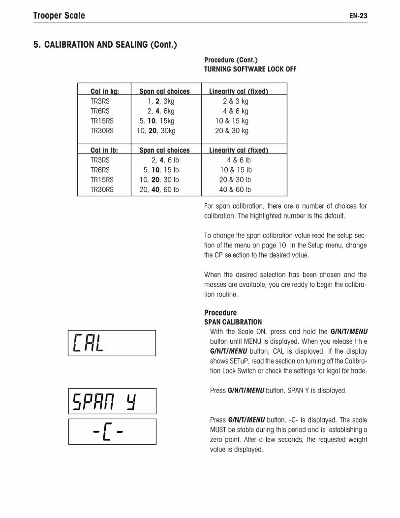
Cal in kg: Span cal choices Linearity cal (fixed)TR3RS 1, 2, 3kg 2 & 3 kgTR6RS 2, 4, 6kg 4 & 6 kgTR15RS 5, 10, 15kg 10 & 15 kgTR30RS 10, 20, 30kg 20 & 30 kg
Cal in lb: Span cal choices Linearity cal (fixed)TR3RS 2, 4, 6 lb 4 & 6 lbTR6RS 5, 10, 15 lb 10 & 15 lbTR15RS 10, 20, 30 lb 20 & 30 lbTR30RS 20, 40, 60 lb 40 & 60 lb
5. CALIBRATION AND SEALING (Cont.)
Procedure (Cont.)TURNING SOFTWARE LOCK OFF
For span calibration, there are a number of choices forcalibration. The highlighted number is the default.
To change the span calibration value read the setup sec-tion of the menu on page 10. In the Setup menu, changethe CP selection to the desired value.
When the desired selection has been chosen and themasses are available, you are ready to begin the calibra-tion routine.
ProcedureSPAN CALIBRATION
With the Scale ON, press and hold the G/N/T/MENUbutton until MENU is displayed. When you release t h eG/N/T/MENU button, CAL is displayed. If the displayshows SETuP, read the section on turning off the Calibra-tion Lock Switch or check the settings for legal for trade.
Press G/N/T/MENU button, SPAN Y is displayed.
Press G/N/T/MENU button, -C- is displayed. The scaleMUST be stable during this period and is establishing azero point. After a few seconds, the requested weightvalue is displayed.

EN-24 Trooper Scale
Place the indicated mass on the platform. Keep the plat-form stable during this period. The sample illustrationindicates a 15kg scale.
If at this point you are uncertain of the process or if thecorrect weights are not available, the calibration routinecan be aborted by pressing the PRINT/UNITS button, orby turning the scale off by pressing and holding the ON/ZERO/OFF button.
Press G/N/T/MENU button, -C- is displayed while theScale stores the reading and then displays the weight ofthe mass.
If the calibration was successful, the calibration mass isdisplayed and the calibration data is saved automati-cally. If unsuccessful, refer to the troubleshooting sec-tion.
Remove calibration masses from platform.
After the calibration routine is complete, check the scaleagain to see if the scale has been accurately calibrated.If so return to the lockout menu and restore the calibra-tion software lock to “ON”:
Gross Brutto
NOTE: If the Scale is to be used for legal for trade applica-tions, it must be calibrated and the LFT Lock Switch mustbe set ON to lock out the menus. Refer to paragraph 5.1for sealing for legal for trade use.
Procedure (Cont.)SPAN CALIBRATION
5. CALIBRATION AND SEALING (Cont.)
*

EN-25Trooper Scale
ProcedureTURNING CALIBRATION LOCK SWITCH ONTo turn the software lock on:
Press and hold the G/N/T/MENU button until MENU ap-pears. Release it and SETuP appears. (if already in themain menu, skip to the next step).
Repeatedly press the PRINT/UNITS button until LOCSWis displayed.
Repeatedly press the G/N/T/MENU button until LCL OFFis displayed.
Press the PRINT/UNITS button to scroll through thechoices until LCLON appears.
Press the G/N/T/MENU button repeatedly until the scalereturns to weighing
The scale is now ready for weighing.
5. CALIBRATION AND SEALING (Cont.)
EN-26 Trooper Scale
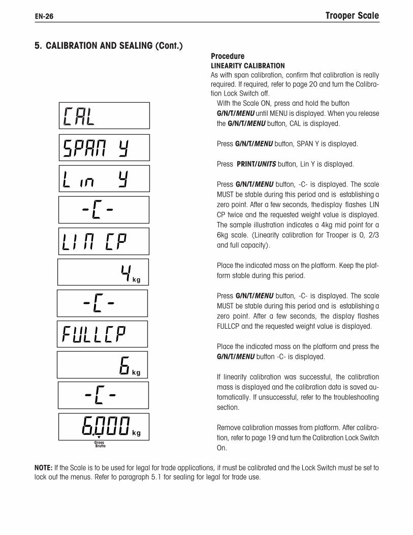
ProcedureLINEARITY CALIBRATIONAs with span calibration, confirm that calibration is reallyrequired. If required, refer to page 20 and turn the Calibra-tion Lock Switch off.
With the Scale ON, press and hold the buttonG/N/T/MENU until MENU is displayed. When you releasethe G/N/T/MENU button, CAL is displayed.
Press G/N/T/MENU button, SPAN Y is displayed.
Press PRINT/UNITS button, Lin Y is displayed.
Press G/N/T/MENU button, -C- is displayed. The scaleMUST be stable during this period and is establishing azero point. After a few seconds, thedisplay flashes LINCP twice and the requested weight value is displayed.The sample illustration indicates a 4kg mid point for a6kg scale. (Linearity calibration for Trooper is 0, 2/3and full capacity).
Place the indicated mass on the platform. Keep the plat-form stable during this period.
Press G/N/T/MENU button, -C- is displayed. The scaleMUST be stable during this period and is establishing azero point. After a few seconds, the display flashesFULLCP and the requested weight value is displayed.
Place the indicated mass on the platform and press theG/N/T/MENU button -C- is displayed.
If linearity calibration was successful, the calibrationmass is displayed and the calibration data is saved au-tomatically. If unsuccessful, refer to the troubleshootingsection.
Remove calibration masses from platform. After calibra-tion, refer to page 19 and turn the Calibration Lock SwitchOn.
Gross Brutto
NOTE: If the Scale is to be used for legal for trade applications, it must be calibrated and the Lock Switch must be set tolock out the menus. Refer to paragraph 5.1 for sealing for legal for trade use.
5. CALIBRATION AND SEALING (Cont.)
kg
kg
kg

EN-27Trooper Scale
GEOGRAPHICAL FACTOR (For Europe Only)
Press the G/N/T/Menu button, gEO 19 is displayed. This is the current geographi-cal adjustment value.
The geo factor includes settings from 0 to 31 and is used to compensate forvarying gravity at different geographical areas (complete geographical adjustmentsettings are listed in the following table).
NOTE:Only an authorized manufacturer’s representative or certified verification
personnel may make these changes.Changing the geographical setting alters the calibration values.
Press the Print/Units button until the desired geographical adjustment value isreached. The factory default setting is gEO 19
SAVEPress the G/N/T/Menu button to end this block, SAVE is displayed.
Press the G/N/T/Menu button to save the geographical factor setting. The nextmenu SEt uP is displayed.
or
Press the Print/Units button to go back to the CAL menu without saving changes tothe geographical setting.
QUITTo exit from the CAL menu, press the Print/Units button to advance to Quit. Thenpress the G/N/T/Menu button to go back to the weighing mode.

EN-28 Trooper Scale
Elevation above sea level in meters0 325 650 975 1300 1625 1950 2275 2600 2925 3250
Geographical latitude in 325 650 975 1300 1625 1950 2275 2600 2925 3250 3575the northern or southern Elevation above sea level in feethemisphere in degrees 0 1060 2130 3200 4260 5330 6400 7460 8530 9600 10660and minutes 1060 2130 3200 4260 5330 6400 7460 8530 9600 10660 117300°0'-5°46’ 5 4 4 3 3 2 2 1 1 0 05°46'-9°52’ 5 5 4 4 3 3 2 2 1 1 09°52'-12°44’ 6 5 5 4 4 3 3 2 2 1 112°44'-15°6’ 6 6 5 5 4 4 3 3 2 2 115°6'-17°10’ 7 6 6 5 5 4 4 3 3 2 217°10'-19°2’ 7 7 6 6 5 5 4 4 3 3 219°2'-20°45’ 8 7 7 6 6 5 5 4 4 3 320°45'-22°22’ 8 8 7 7 6 6 5 5 4 4 322°22'-23°54’ 9 8 8 7 7 6 6 5 5 4 423°54'-25°21’ 9 9 8 8 7 7 6 6 5 5 425°21'-26°45’ 10 9 9 8 8 7 7 6 6 5 526°45'-28°6’ 10 10 9 9 8 8 7 7 6 6 528°6'-29°25’ 11 10 10 9 9 8 8 7 7 6 629°25'-30°41’ 11 11 10 10 9 9 8 8 7 7 630°41'-31°56’ 12 11 11 10 10 9 9 8 8 7 731°56'-33°9’ 12 12 11 11 10 10 9 9 8 8 733°9'-34°21’ 13 12 12 11 11 10 10 9 9 8 834°21' - 35° 31' 13 13 12 12 11 11 10 10 9 9 835°31' - 36° 41' 14 13 13 12 12 11 11 10 10 9 936°41' - 37° 50' 14 14 13 13 12 12 11 11 10 10 937°50' - 38° 58' 15 14 14 13 13 12 12 11 11 10 1038°58' - 40° 5' 15 15 14 14 13 13 12 12 11 11 1040° 5' - 41° 12' 16 15 15 14 14 13 13 12 12 11 1141°12' - 42° 19' 16 16 15 15 14 14 13 13 12 12 1142°19' - 43° 26' 17 16 16 15 15 14 14 13 13 12 1243°26' - 44° 32' 17 17 16 16 15 15 14 14 13 13 1244°32' - 45° 38' 18 17 17 16 16 15 15 14 14 13 1345°38' - 46° 45' 18 18 17 17 16 16 15 15 14 14 1346°45' - 47° 51' 19 18 18 17 17 16 16 15 15 14 1447°51' - 48° 58' 19 19 18 18 17 17 16 16 15 15 1448°58' - 50° 6' 20 19 19 18 18 17 17 16 16 15 1550° 6' - 51° 13' 20 20 19 19 18 18 17 17 16 16 1551°13' - 52° 22' 21 20 20 19 19 18 18 17 17 16 1652°22' - 53° 31' 21 21 20 20 19 19 18 18 17 17 1653°31' - 54° 41' 22 21 21 20 20 19 19 18 18 17 1754°41' - 55° 52' 22 22 21 21 20 20 19 19 18 18 1755°52' - 57° 4' 23 22 22 21 21 20 20 19 19 18 1857° 4' - 58° 17' 23 23 22 22 21 21 20 20 19 19 1858°17' - 59° 32' 24 23 23 22 22 21 21 20 20 19 1959°32' - 60° 49' 24 24 23 23 22 22 21 21 20 20 1960°49' - 62° 9' 25 24 24 23 23 22 22 21 21 20 2062° 9' - 63° 30' 25 25 24 24 23 23 22 22 21 21 2063°30' - 64° 55' 26 25 25 24 24 23 23 22 22 21 2164°55' - 66° 24' 26 26 25 25 24 24 23 23 22 22 2166°24' - 67° 57' 27 26 26 25 25 24 24 23 23 22 2267°57' - 69° 35' 27 27 26 26 25 25 24 24 23 23 2269°35' - 71° 21' 28 27 27 26 26 25 25 24 24 23 2371°21' - 73° 16' 28 28 27 27 26 26 25 25 24 24 2373°16' - 75° 24' 29 28 28 27 27 26 26 25 25 24 2475°24' - 77° 52' 29 29 28 28 27 27 26 26 25 25 2477°52' - 80° 56' 30 29 29 28 28 27 27 26 26 25 2580°56' - 85° 45' 30 30 29 29 28 28 27 27 26 26 2585°45' - 90° 00' 31 30 30 29 29 28 28 27 27 26 26
GEOGRAPHICAL ADJUSTMENT VALUESGEOGRAPHICAL FACTOR (cont.)

EN-29Trooper Scale
PAPER SEALS
5.1 Legal for Trade (LFT) Operation and LFT SealingBefore this product can be used in legal-for-trade or legally controlled applications, it must be inspected in accordancewith local weights and measures or approval agency regulations. It is the responsibility of the purchaser to ensure thatall pertinent legal requirements are met. Please contact your local weights and measures office or authorizedmanufacturer's representative for further details.
Legal for Trade (LFT) operation is possible through a LFT Lock Switch located on the PC board. The Scale must becalibrated prior to performing this procedure.
ProcedureSet up Scale, and calibrate. After this is done, removepower from the Scale.
Turn the scale over in the position as shown and removethe Lock Switch cover plate.
Refer to the illustration at the left and notice the positionof the LFT switch. To lock out the menus, slide the LFTswitch to the position shown.
Replace the Lock Switch cover and housing screw cover.The two screws are cross drilled and can accept a wireseal.
NOTICE: The Trooper Scale has been tested and found tocomply with Class lll requirements of NIST Handbook 44.
After the Scale has been tested and found to comply withlocal applicable regulations by a local weights and mea-sures official, it may be sealed as follows:
LEAD AND WIRE SEALSee illustration atleft. Place wire seal through the holesin the screw and ribs as shown and compress the leadseal in place.
PAPER SEALIf an audit trail or paper seal will be used, place a paperseal over both access covers.
Bottom of Trooper
Sealing the Scale with a Lead Seal
LFT OFF(UNLOCKED)
LFT ON(LOCKED)
Sealing the Scale with a Paper Seal

EN-30 Trooper Scale
6 CARE AND MAINTENANCETo keep the Scale operating properly, the housing should be kept clean and free from foreign material. If necessary, acloth dampened with a mild detergent may be used.
6.1 Troubleshooting
SYMPTOM
Unit will not turn on.
Cannot zero Scale, or will not zerowhen turned on.
Center of Zero display indicator er-ratic or does not appear with noload on scale platform.
REMEDY
Check power cord connections.
Make sure adapter connector isplugged all the way into the Scale.
Check battery connector.
Check orientation of the batteries.
Replace batteries.
Check functions of membraneswitch.
Remove load on scale to less thanentered zero %.
Change allowable zero % in ZEROparameter of Setup menu.
Normal operation when this fea-ture is disabled.
Remove disturbances or reducemotion.
Increase AZT level in readoutmenu.
Increase averaging level in read-out menu.
PROBABLE CAUSE(S)
Adapter not plugged in or properlyconnected.
Batteries dead or not properlyinstalled.
Membrane switch failure.
Load on scale exceeds allowable zero% entered in ZERO parameter of Setupmenu.
Retain Zero Data is enabled in scalemenu.
Scale platform motion or disturbancesexceed center of zero criteria.

EN-31Trooper Scale
6 CARE AND MAINTENANCE (Cont.)
Cannot display weight in desiredweighing unit.
RS232 not working.
Unable to calibrate unit.
Desired unit not set to ON in Readoutmenu.
RS232 communication parameters set upincorrectly.
Improper or loose cable connections.
Software Lockout switch set to ON andLock Switch on the circuit board set toopen position.
Incorrect value for calibration mass.
Enable desired unit in Readoutmenu. See paragraph 4.4.4
Conversion too large (typically ing).
Verify communication param-eters.
Check cable connections.
Set LCL to OFF in the LocSWmenu, and set Lock Switch on thecircuit board to ON position. Re-fer to paragraph 4.4.6.
Use correct calibration mass.
SYMPTOM PROBABLE CAUSE(S) REMEDY
6.1 Troubleshooting (Cont.)

EN-32 Trooper Scale
6.2 Error Codes List
The following list describes the various error codes which can appear on the display.
LoBat Is indicated when batteries are weak. Approximately 20 minutes of operating time remain.
Error 1 Indicates an overload condition.
Error 2 Indicates an underload condition.
Error 7 EEPROM data incorrect.
Error 14 Zero exceeds ZERO% and cannot be zeroed.
Err 21 Calibration data does not match current full scale, Grad and Cal Point settings. Settings mustbe restored or the Scale must be recalibrated using the current settings.
6.3 Service InformationIf the Troubleshooting section does not resolve or describe your problem, you will need to contact an authorized OhausService Agent. For Service assistance in the United States, please call Aftermarket, Ohaus Corporation toll-free at (800)526-0659. An Ohaus Product Service Specialist will be available to help you.
6.4 AccessoriesDescription Ohaus Part No. RS232 Interface Cable/SF42 Printer 80500573 RS232 Interface Cable/PC 25 Pin 80500431 RS232 Interface Cable/PC 9 Pin 80500433 Printer SF42
6.5 Technical DataMaterials ABS Housing Keypad/display overlay polyester
EN-33Trooper Scale
General Specifications Platform Size (w x d) (in/cm) 13.5 X 9" / 34 X 23 Scale Dimensions (w x d x h) (in/cm) 13.5 X 14.5 X 4.5 / 34.3 X 36.8 X 11.4
Shipping Dimensions (w x d x h) (in/cm) 17 X 17 X 8.5 / 42.2 X 42.2 X 21.6 Weight (lb/kg) 8.6 / 3.9 Resolution NTEP 1:3000
Resolution Maximum 6,000 - 7,500 depending on model Stabilization time 1 - 4 seconds depending upon filter selection Keyboard 4 function membrane switches
Weighing units lb, kg, g, oz Display Backlit LCD, 25.4mm, 1" Power AC Adapter or 6 alkaline C-type batteries Typical Battery Life Up to 100 hours Span Calibration 1/3 to full capacity
Linearity Calibration (3-point calibration) All models Auto-zero tracking Off, 0.5, 1, or 3 divisions Construction Stainless steel weighing pan, ABS plastic housing
Protection IP43 Operating Temperature 41°F to 104°F / 5°C to 40°C Storage Temperature -40°F to 140°F / -40°C to 60°C
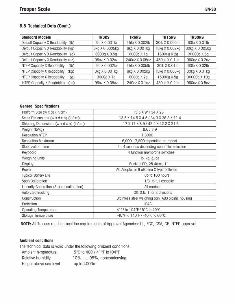
6.5 Technical Data (Cont.)
Standard Models TR3RS TR6RS TR15RS TR30RS Default Capacity X Readability (lb) 6lb X 0.001lb 15lb X 0.002lb 30lb X 0.005lb 60lb X 0.01lb Default Capacity X Readability (kg) 3kg X 0.0005kg 6kg X 0.001kg 15kg X 0.002kg 30kg X 0.005kg
Default Capacity X Readability (g) 3000g X 0.5g 6000g X 1g 15000g X 2g 30000g X 5g Default Capacity X Readability (oz) 96oz X 0.02oz 240oz X 0.05oz 480oz X 0.1oz 960oz X 0.2oz NTEP Capacity X Readability (lb) 6lb X 0.002lb 15lb X 0.005lb 30lb X 0.01lb 60lb X 0.02lb
NTEP Capacity X Readability (kg) 3kg X 0.001kg 6kg X 0.002kg 15kg X 0.005kg 30kg X 0.01kg NTEP Capacity X Readability (g) 3000g X 1g 6000g X 2g 15000g X 5g 30000g X 10g NTEP Capacity X Readability (oz) 96oz X 0.05oz 240oz X 0.1oz 480oz X 0.2oz 960oz X 0.5oz
NOTE: All Trooper models meet the requirements of Approval Agencies: UL, FCC, CSA, CE. NTEP approval.
Ambient conditionsThe technical data is valid under the following ambient conditions: Ambient temperature 5°C to 40C / 41°F to104°F Relative humidity 10%.......95%, noncondensing Height above sea level up to 4000m

EN-34 Trooper Scale
LIMITED WARRANTY
Ohaus products are warranted against defects in materials and workmanship from the date of delivery through theduration of the warranty period. During the warranty period Ohaus will repair, or, at its option, replace any component(s) that proves to be defective at no charge, provided that the product is returned, freight prepaid, to Ohaus.
This warranty does not apply if the product has been damaged by accident or misuse, exposed to radioactive orcorrosive materials, has foreign material penetrating to the inside of the product, or as a result of service or modificationby other than Ohaus. In lieu of a properly returned warranty registration card, the warranty period shall begin on the dateof shipment to the authorized dealer. No other express or implied warranty is given by Ohaus Corporation. OhausCorporation shall not be liable for any consequential damages.
As warranty legislation differs from state to state and country to country, please contact Ohaus or your local Ohausdealer for further details.
Test Equipment Depot - 800.517.8431 - 99 Washington Street Melrose, MA 02176 - TestEquipmentDepot.com