TRNEdit: Editing the Input File and Creating TRNSED...
110
TRNSYS 16 a TRaN sient SY stem S imulation program Volume 7 TRNEdit: Editing the Input File and Creating TRNSED Application Solar Energy Laboratory, Univ. of Wisconsin-Madison http://sel.me.wisc.edu/trnsys TRANSSOLAR Energietechnik GmbH http://www.transsolar.com CSTB – Centre Scientifique et Technique du Bâtiment http://software.cstb.fr TESS – Thermal Energy Systems Specialists http://www.tess-inc.com
Transcript of TRNEdit: Editing the Input File and Creating TRNSED...
TRNSYS 16
a T R a N s i e n t S Y s t e m S i m u l a t i o n p r o g r a m
Volume 7
TRNEdi t : Ed i t ing the Input F i le and Creat ing TRNSED
Appl icat ion
Solar Energy Laboratory, Univ. of Wisconsin-Madisonhttp://sel.me.wisc.edu/trnsys
TRANSSOLAR Energietechnik GmbH http://www.transsolar.com
CSTB – Centre Scientifique et Technique du Bâtimenthttp://software.cstb.fr
TESS – Thermal Energy Systems Specialists http://www.tess-inc.com
TRNSYS 16 – TRNEdit: Editing the Input File and Creating TRNSED Application
2�
About This Manual The information presented in this manual is intended to provide a detailed reference guide on TRNEdit, the TRNSYS Editor, and on how to create stand-alone distributable applications known as TRNSED applications. It also provides information on the TRNSYS input file syntax. This manual is not intended to provide detailed reference information about the TRNSYS simulation software itself or its other utility programs. More details can be found in other parts of the TRNSYS documentation set. The latest version of this manual is always available for registered users on the TRNSYS website (see here below).
Revision history • 2004-09 For TRNSYS 16.00.0000 • 2005-02 For TRNSYS 16.00.0037 • 2006-01 For TRNSYS 16.01.0000 • 2006-06 For TRNSYS 16.01.0002 • 2007-02 For TRNSYS 16.01.0003
Where to find more information Further information about the program and its availability can be obtained from the TRNSYS website or from the TRNSYS coordinator at the Solar Energy Lab:
TRNSYS Coordinator Solar Energy Laboratory, University of Wisconsin-Madison 1500 Engineering Drive, 1303 Engineering Research BuildingMadison, WI 53706 – U.S.A.
Email: [email protected]: +1 (608) 263 1586 Fax: +1 (608) 262 8464
TRNSYS website: http://sel.me.wisc.edu/trnsys
Notice This report was prepared as an account of work partially sponsored by the United States Government. Neither the United States or the United States Department of Energy, nor any of their employees, nor any of their contractors, subcontractors, or employees, including but not limited to the University of Wisconsin Solar Energy Laboratory, makes any warranty, expressed or implied, or assumes any liability or responsibility for the accuracy, completeness or usefulness of any information, apparatus, product or process disclosed, or represents that its use would not infringe privately owned rights.
© 2007 by the Solar Energy Laboratory, University of Wisconsin-Madison
The software described in this document is furnished under a license agreement. This manual and the software may be used or copied only under the terms of the license agreement. Except as permitted by any such license, no part of this manual may be copied or reproduced in any form or by any means without prior written consent from the Solar Energy Laboratory, University of Wisconsin-Madison.
TRNSYS 16 – TRNEdit: Editing the Input File and Creating TRNSED Application
3�
TRNSYS Contributors
S.A. Klein W.A. Beckman J.W. Mitchell
J.A. Duffie N.A. Duffie T.L. Freeman
J.C. Mitchell J.E. Braun B.L. Evans
J.P. Kummer R.E. Urban A. Fiksel
J.W. Thornton N.J. Blair P.M. Williams
D.E. Bradley T.P. McDowell M. Kummert
D.A. Arias
Additional contributors who developed components that have been included in the Standard Library are listed in Volume 5.
Contributors to the building model (Type 56) and its interface (TRNBuild) are listed in Volume 6.
Contributors to the TRNSYS Simulation Studio are listed in Volume 2.

TRNSYS 16 – TRNEdit: Editing the Input File and Creating TRNSED Application
4�
TRNSYS 16 – TRNEdit: Editing the Input File and Creating TRNSED Application
5�
TABLE OF CONTENTS
7. TRNEDIT: EDITING THE INPUT FILE AND CREATING TRNSED APPLICATION 10 7.1. How to use TRNEdit 12
7.1.1. Editing and running TRNSYS Input files 12 7.1.2. Parametric runs 14
7.1.2.1. Preparing the input file 14 Input and output files 14 Identifying the parameters for the study 14
7.1.2.2. Creating the parametric table 15 7.1.2.3. Running the table 15 7.1.2.4. Analyzing the results 16
7.2. Input file syntax 17 7.3. Simulation control statements 19
7.3.1. The VERSION Statement 19 7.3.2. The SIMULATION Statement 19 7.3.3. Convergence Tolerances (TOLERANCES) 19 7.3.4. The LIMITS Statement 20 7.3.5. The NAN_CHECK Statement 21 7.3.6. The OVERWRITE_CHECK Statement 21 7.3.7. The TIME_REPORT Statement 22 7.3.8. The CONSTANTS Statement 22 7.3.9. The EQUATIONS Statement 23
7.3.9.1. Available mathematical functions 24 7.3.9.2. Additional checking functions 26
7.3.10. The Convergence Promotion Statement (ACCELERATE) 26 7.3.11. The Calling Order Specification Statement (LOOP) 28 7.3.12. The Differential Equation Solving Method Statement (DFQ) 30 7.3.13. The Convergence Check Suppression Statement (NOCHECK) 30 7.3.14. The Equation Solving Method Statement (EQSOLVER) 32 7.3.15. The SOLVER Statement 32
7.3.15.1. Solver 0: Successive substitution 33 The ACCELERATE statement 33 Numerical relaxation 33 Implementation of the relaxation in TRNSYS 36
7.3.15.2. Solver 1: Powell's method 36 Backsolving and Discrete variables in TRNSYS 36
7.3.16. The ASSIGN Statement and Logical Unit Numbers 40
TRNSYS 16 – TRNEdit: Editing the Input File and Creating TRNSED Application
6�
7.3.17. The INCLUDE Statement 41 7.3.18. The END Statement 41
7.4. Component Control Statements 42 7.4.1. The UNIT-TYPE Statement 42 7.4.2. The PARAMETERS Statement 43 7.4.3. The INPUTS Statement 44 7.4.4. The DERIVATIVES Statement 46 7.4.5. The TRACE Statement 47 7.4.6. The ETRACE Statement 48 7.4.7. The FORMAT Statement 48
7.5. Listing Control Statements 50 7.5.1. The WIDTH Statement 50 7.5.2. The NOLIST Statement 50 7.5.3. The LIST Statement 51 7.5.4. The MAP Statement 51
7.6. Comment Lines 52 7.7. Control Statement Example 54 7.8. Data Echo and Control Statement Errors 56 7.9. Summary of Input File Syntax 58 7.10. How to create TRNSED applications 60
7.10.1. Starting point: TRNSYS Studio project 60 7.10.2. Editing the TRNSED file in TRNEdit 62 7.10.3. Basic formatting 62 7.10.4. Some common tasks 65
7.10.4.1. Adding an input field 65 7.10.4.2. Reorganizing TRNSED fields 66
7.10.5. Adding pictures and links 67 7.10.5.1. Pictures 67 7.10.5.2. Links 68
7.10.6. Multiple tabs 69 7.10.6.1. Adding multiple tabs 69 7.10.6.2. Links between tabs 69
7.10.7. Adding "hot spots" to pictures 70 7.10.7.1. Defining the map of clickable areas 70 7.10.7.2. Telling TRNSED to use a map with an image 70
7.10.8. Adding a pull-down menu for file selection 71 7.10.9. Adding a pull-down menu for other parameters 72 7.10.10. Mutually exclusive choices: Radio Buttons 74 7.10.11. Non-exclusive options: check boxes 75 7.10.12. Providing help in TRNSED applications 77
TRNSYS 16 – TRNEdit: Editing the Input File and Creating TRNSED Application
7�
7.10.12.1. Text-based help 77 7.10.12.2. Help through external applications 77
7.10.13. Creating the redistributable application 78 7.10.13.1. Preparing the file 78 7.10.13.2. Creating the distributable 79
7.11. TRNSED language reference 82 7.11.1. Declaring the input file as a TRNSED file 83 7.11.2. Format statements 83
7.11.2.1. Background 83 7.11.2.2. Images 83 7.11.2.3. Text formatting 83
Color 84 Font 84 Size 84 Style 84 Align 85 Tab 85
7.11.3. TRNSED Data Entry fields 85 7.11.3.1. Value input fields 85 7.11.3.2. Pull-down menu fields 86
Hidden fields 87 7.11.3.3. TRNSED Assign statements 88
ASSIGN "Open File" Dialog Box Statement 88 ASSIGN File Reference Statement 88
7.11.4. Grouping TRNSED statements 88 7.11.4.1. Multiple Tabs 88 7.11.4.2. Standard TRNSED Groups 89 7.11.4.3. Radio button group: Mutually exclusive options 90 7.11.4.4. Check box group: non-exclusive options 90
7.11.5. Actions when an image is clicked 91 7.11.5.1. Links between tabs 91 7.11.5.2. Links to external applications 91 7.11.5.3. Clickable areas in pictures ("hot spots") 91
7.11.6. Pre- and post-processing actions 92 7.11.7. Providing help in TRNSED 93
7.11.7.1. Help as HTML, PDF, etc. documents 93 7.11.7.2. Text-based help 93
7.11.8. Using TRNSED Index Files (.idx) 93
TRNSYS 16 – TRNEdit: Editing the Input File and Creating TRNSED Application
8�
7.12. TRNEdit menu reference 96 7.12.1. File Menu 96
7.12.1.1. File/New 96 7.12.1.2. File/Open 96 7.12.1.3. File/Save 97 7.12.1.4. File/Save As 97 7.12.1.5. File/Print 97 7.12.1.6. File/Printer Setup 98 7.12.1.7. File/Setup 98
File/Setup/TRNSED 98 File/Setup/Links 99 File/Setup/Fonts 99
7.12.1.8. File/Exit 100 7.12.2. Edit Menu 100 7.12.3. TRNSYS Menu 100
7.12.3.1. TRNSYS/Calculate 100 7.12.3.2. TRNSYS/Run Table (TRNSYS/Stop Table) 100
Run Table 100 Stop Table 101
7.12.3.3. TRNSYS/Compile Module, TRNSYS/Rebuild TRNSYS 101 7.12.4. TRNSED Menu 101
7.12.4.1. TRNSED/Create Distributable 101 .EXE name 102 TRNSED ID only 102 Title and Author 102 Destination Directory 102 Include the following files 102
7.12.5. Parametrics Menu 103 7.12.5.1. Performing parametric studies in TRNSYS 103 7.12.5.2. Parametrics/New Table 103 7.12.5.3. Parametrics/Alter Table 104 7.12.5.4. Parametrics/Insert/Delete Runs 105 7.12.5.5. Parametrics/Insert-Delete Variables 105
7.12.6. Plot Menu 105 7.12.6.1. Plot/New Plot 105 7.12.6.2. Plot/Overlay Plot 106 7.12.6.3. Plot/Modify Plot 106
7.12.7. The Windows Menu 107
TRNSYS 16 – TRNEdit: Editing the Input File and Creating TRNSED Application
9�
7.12.7.1. Windows/Input 107 7.12.7.2. Windows/Other files 107 7.12.7.3. Windows/Listing 107 7.12.7.4. Windows/Log 107 7.12.7.5. Windows/Table 107 7.12.7.6. Windows/Diagram 108 7.12.7.7. Windows/Tile and Windows/Cascade 108
7.12.8. The Help Menu 108 7.12.9. Right-click menu 108
7.13. References 110
TRNSYS 16 – TRNEdit: Editing the Input File and Creating TRNSED Application
10�
7. TRNEDIT: EDITING THE INPUT FILE AND CREATING TRNSED APPLICATION
Introduction This manual contains information on the TRNEdit program, as well as reference information on the TRNSYS Input file syntax (Section 7.1 and after)
TRNEdit evolved from TRNSHELL, a program that was designed to be the centerpiece of the TRNSYS Suite. The TRNSYS Studio has replaced TRNSHELL in that role, but TRNEdit still provides some unique features:
• Text editing of the input files (for advanced users, see section 7.1.1) • Support for parametric runs (see section 7.1.2) • Editing of TRNSED input files and generation of the distributable programs (see section
7.10)
Sections 0 and 7.10 follow a "how to" approach. A full TRNSED language reference is provided in section 0 and section 0 presents the description of all menu entries in TRNEdit.
Note on licensing aspects of TRNSED applications
Redistributable stand-alone applications based on TRNSYS, known as TRNSED Applications, are subject to a special license agreement. The actual license agreement is provided in the license.txt file, in your TRNSYS installation directory.
The basic terms of the agreement is that you have the right to distribute those applications free of charge and that you have to negotiate a contract with the TRNSYS developers if you want to sell those applications. Please contact your TRNSYS Distributor if you have questions about licensing.
Some distributors may not activate the "Create TRNSED" function by default. If it is the case, the "TRNSED/Create distributable" menu item will be disabled in TRNEDit. You should contact your distributor to activate it.

TRNSYS 16 – TRNEdit: Editing the Input File and Creating TRNSED Application
11�
TRNSYS 16 – TRNEdit: Editing the Input File and Creating TRNSED Application
12�
7.1. How to use TRNEdit
7.1.1. Editing and running TRNSYS Input files
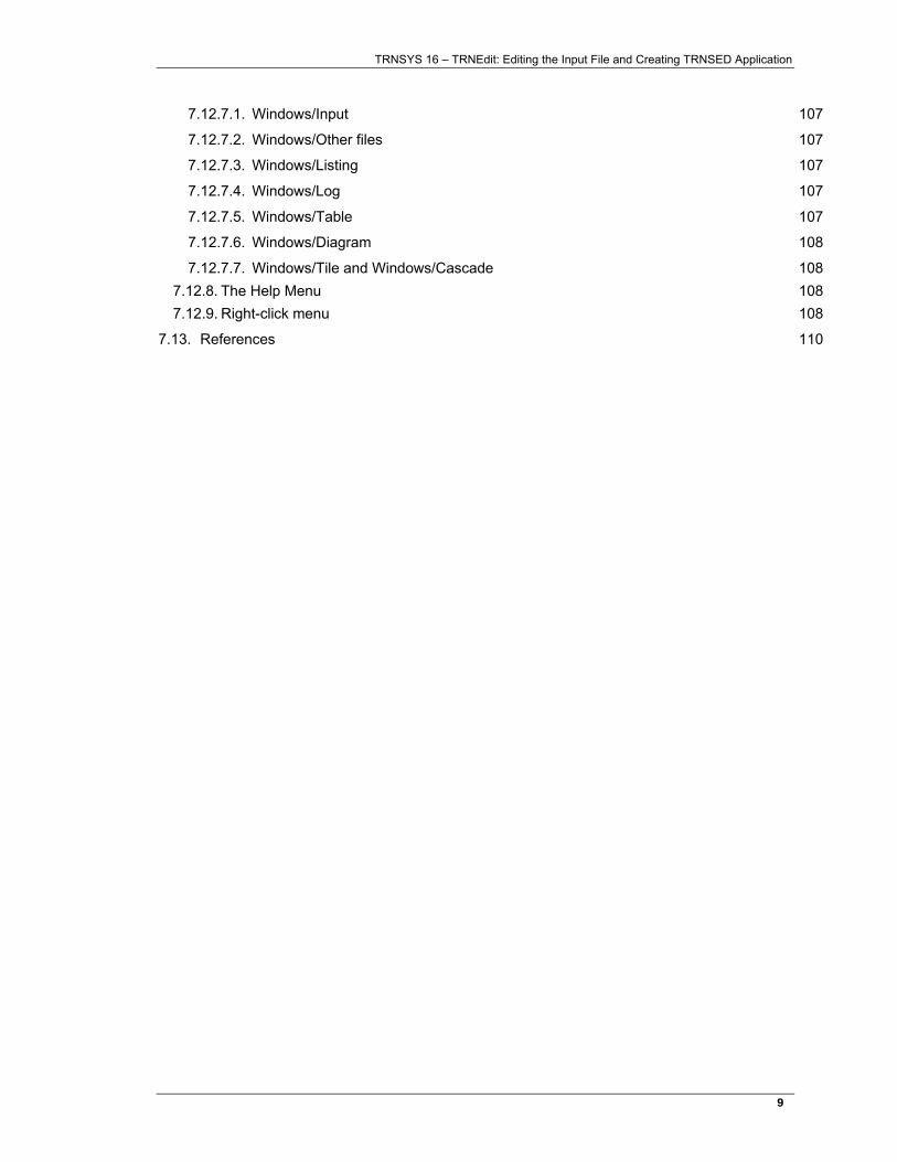
TRNEdit can be used to edit TRNSYS input files (deck files). Launch the program throught the shortcut created by the TRNSYS Setup, and open any input file (standard TRNSYS input files have a .dck extension, TRNSED files have a .trd extension. To open a .dck file, change the filter to display "TRNSYS files" instead of "TRNSED Files".
Figure 7–1: Editing a TRNSYS input file in TRNEdit
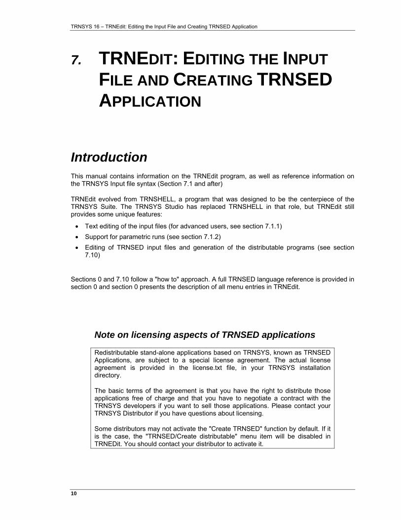
Information on the input file syntax is presented in section 0 and after. Once the input file is ready, the input file can be run using the TRNSYS / Calculate menu or by pressing the F8 key (see Figure 7–2).
After running the simulation, the simulation output files can be accessed through the "Windows" menu. The listing and log files have information on the simulation (notices, warnings, errors) and the "Other files" are the input and output files used in the simulation.
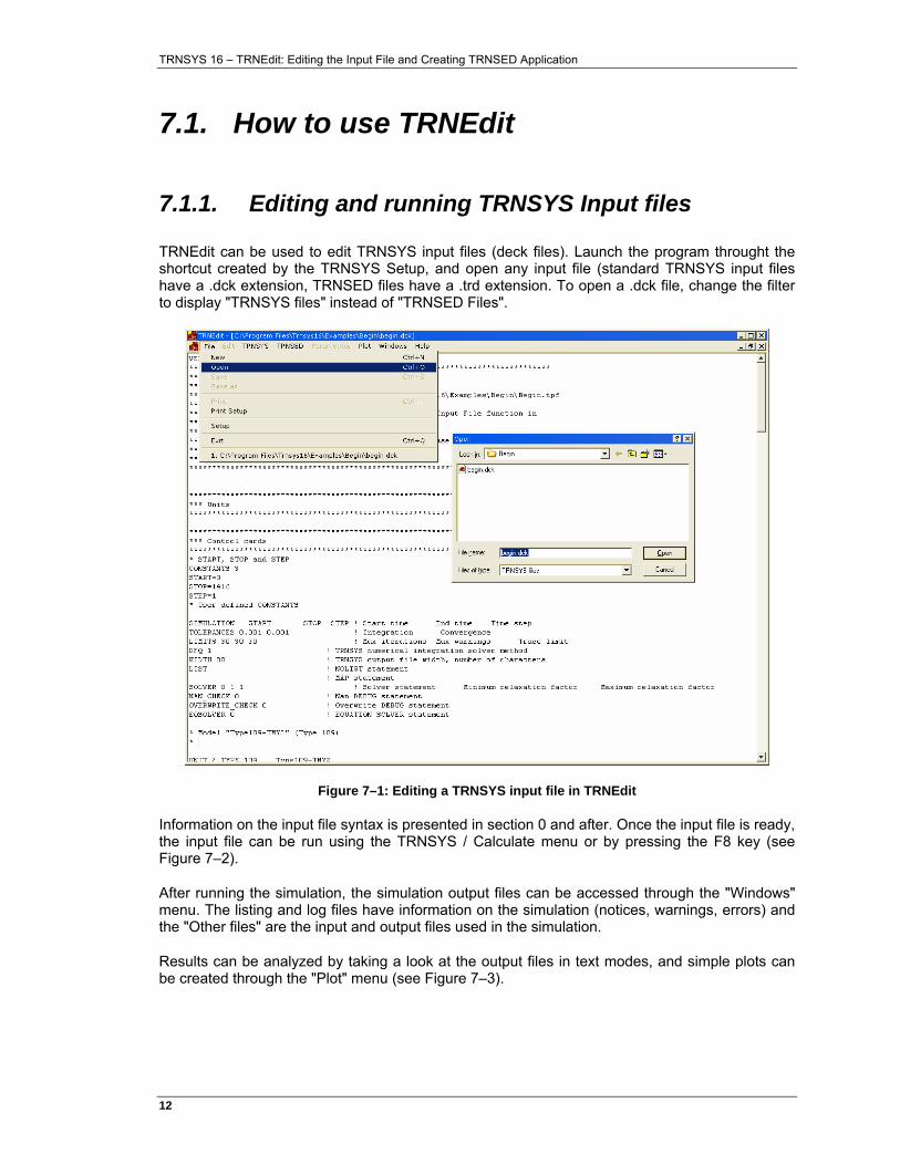
Results can be analyzed by taking a look at the output files in text modes, and simple plots can be created through the "Plot" menu (see Figure 7–3).
TRNSYS 16 – TRNEdit: Editing the Input File and Creating TRNSED Application
13�
Figure 7–2: Running a TRNSYS input file in TRNEdit
Figure 7–3: Analyzing simulation results in TRNEdit
TRNSYS 16 – TRNEdit: Editing the Input File and Creating TRNSED Application
14�
7.1.2. Parametric runs
It is often interesting to run the same TRNSYS simulation with different values of some key parameters. For reference information on Parametric studies in TRNSYS, please see section 7.12.5.
7.1.2.1. Preparing the input file
The input file used in this section is:
\Examples\Parametric Runs\SDHW-ParametricRuns.dck.
It was generated from the TRNSYS Studio project in the same directory, but was then modified to follow the following rules that apply to parametric studies:
INPUT AND OUTPUT FILES
All output files that should be generated for each parametric run must have the same name as the deck file with a different extension (e.g. be assigned to ***.out, ***.ou2, ***.ou3, etc. TRNEdit will automatically append the run number to those files. It will not do this for input/output files that have a different name.
In this example, we are using both features: We always want to use the same weather file, and we will create one summary file (Totals.txt) but the daily results will be printed to a different file for each run. The printer used for Totals.txt is configured to append to the output file and not to print labels (column headers).
IDENTIFYING THE PARAMETERS FOR THE STUDY
The parametric table feature allows to change variables that are declared as CONSTANTS in a TRNSYS input file. The Studio created a deck file with equations, so we need to make a modification: * EQUATIONS "Simulation Parameters" * EQUATIONS 4 AColl = 5.0 DHWDailyLoad = 200 mdCollMax = 40*AColl VStorage = 0.060*AColl ! In m^3 *$UNIT_NAME Simulation Parameters *$LAYER Main *$POSITION 331 136
Becomes: * --- CONSTANTS that come from the "Simulation parameters" block in the Studio CONSTANTS 2 AColl = 5.0 DHWDailyLoad = 200 * --- Other varaibles are left as equations EQUATIONS 2 mdCollMax = 40*AColl VStorage = 0.060*AColl ! In m^3
TRNSYS 16 – TRNEdit: Editing the Input File and Creating TRNSED Application
15�
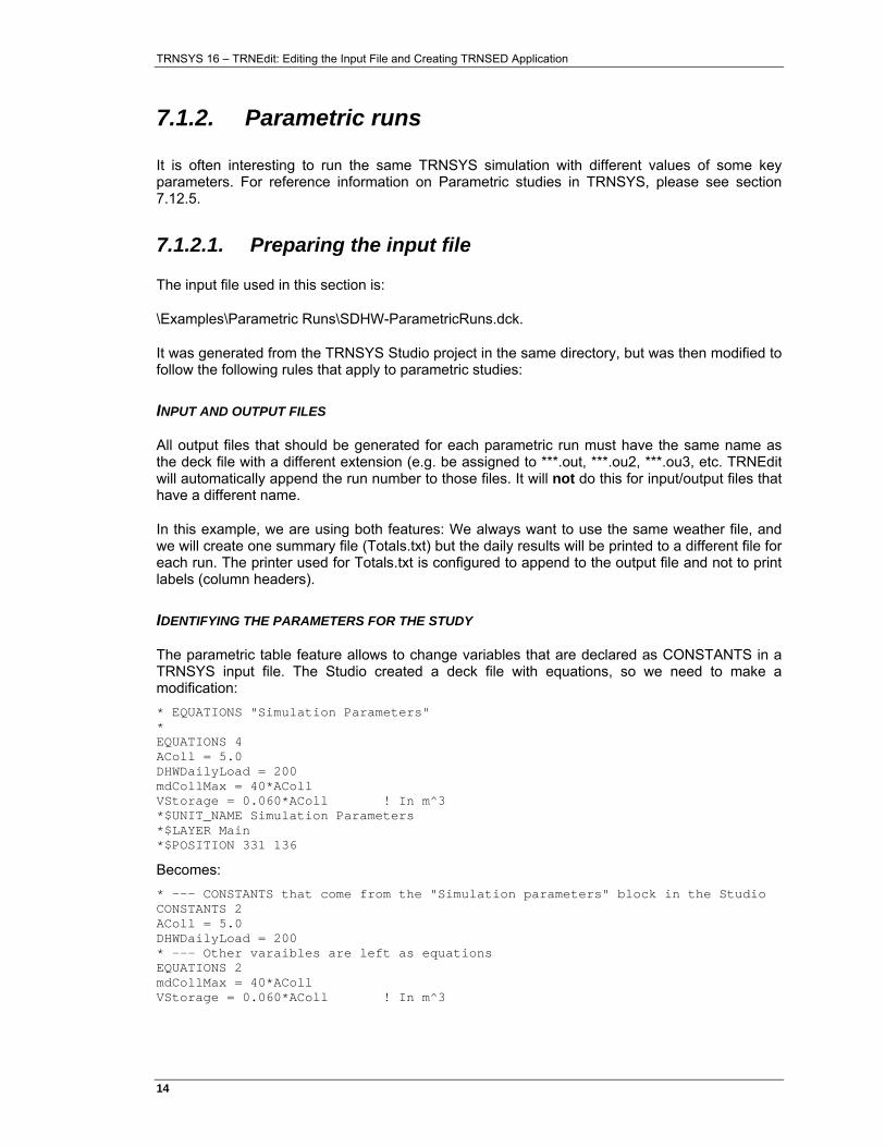
7.1.2.2. Creating the parametric table
The Parametrics / New Table menu will pop-up a window showing all CONSTANTS defined in the input file. You can just add them to the parametric table by selecting them and then clicking on the right array (>). Once the table has been created, values can be filled in as shown in Figure 7–4.
In our case we will study the effect of varying the collector area between 1 and 10 m² (with 5 steps) for two different daily domestic hot water loads, 200 and 300 l/day.
Tables can be saved as .tbl files using the File/Save Menu.
Figure 7–4: Creating a parametric table
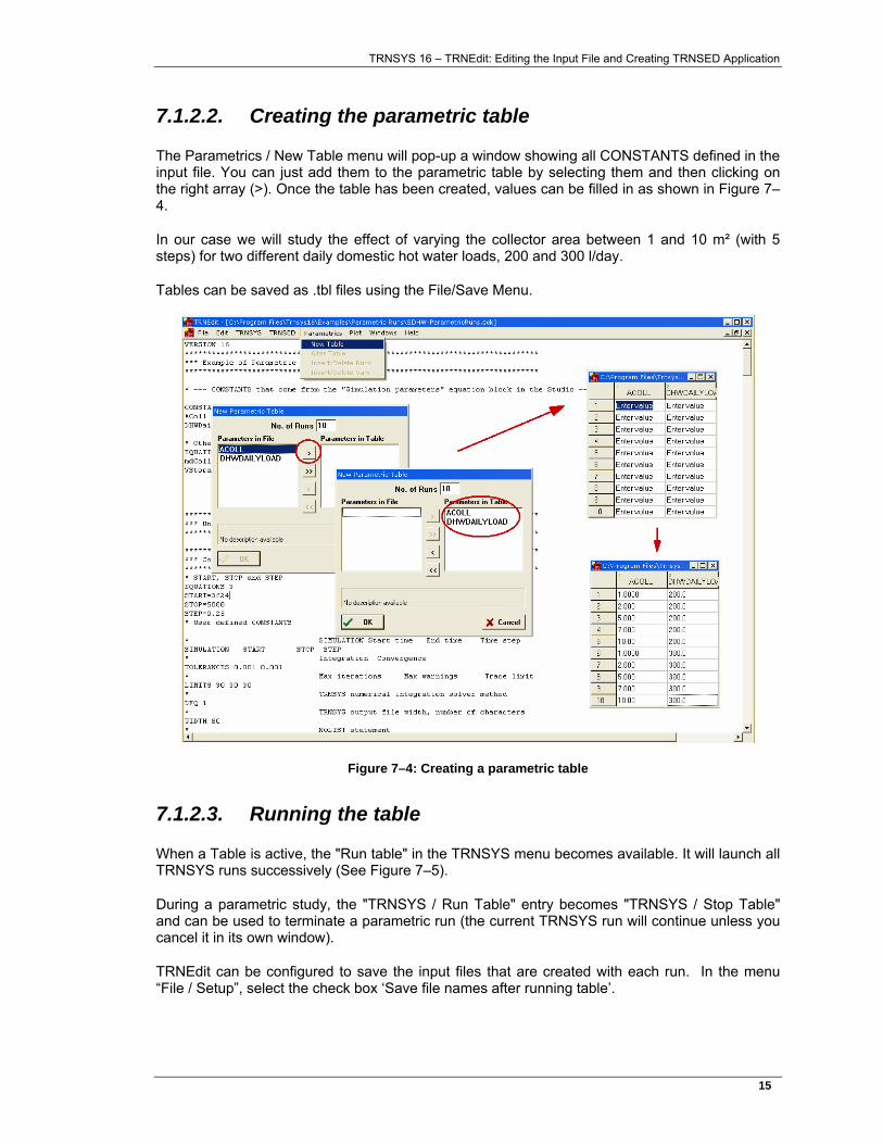
7.1.2.3. Running the table
When a Table is active, the "Run table" in the TRNSYS menu becomes available. It will launch all TRNSYS runs successively (See Figure 7–5).
During a parametric study, the "TRNSYS / Run Table" entry becomes "TRNSYS / Stop Table" and can be used to terminate a parametric run (the current TRNSYS run will continue unless you cancel it in its own window).
TRNEdit can be configured to save the input files that are created with each run. In the menu “File / Setup”, select the check box ‘Save file names after running table’.
TRNSYS 16 – TRNEdit: Editing the Input File and Creating TRNSED Application
16�
Figure 7–5: Running a parametric table
7.1.2.4. Analyzing the results
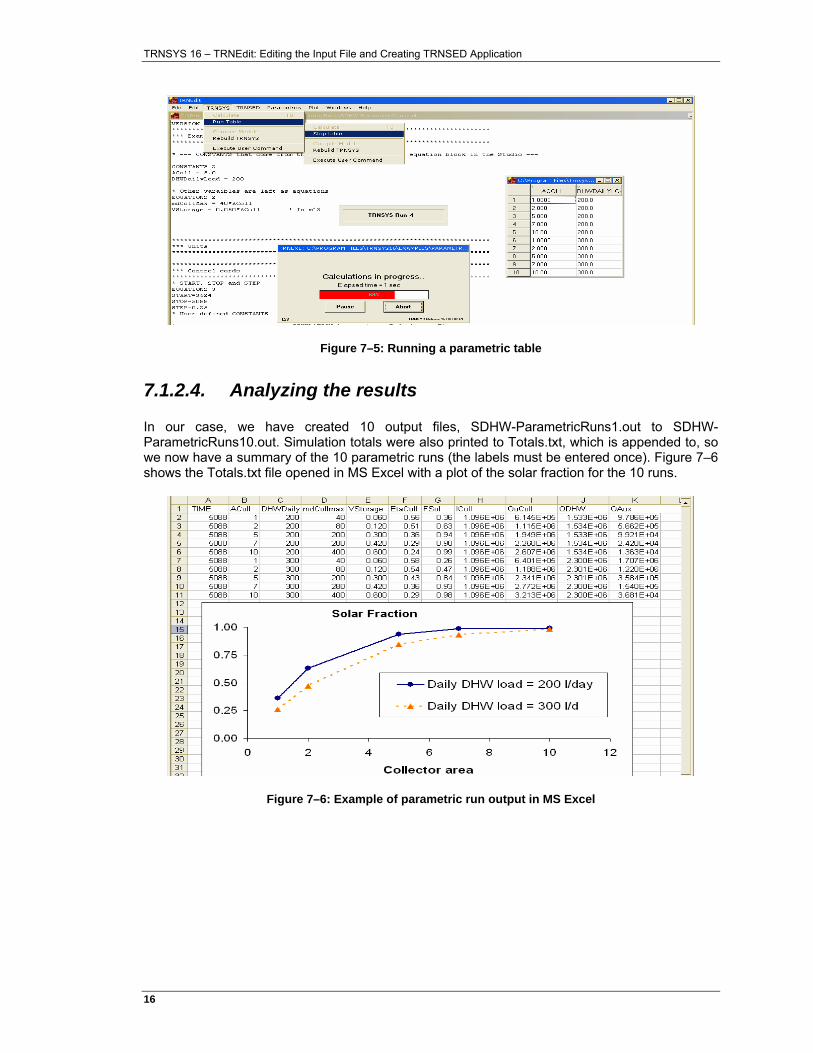
In our case, we have created 10 output files, SDHW-ParametricRuns1.out to SDHW-ParametricRuns10.out. Simulation totals were also printed to Totals.txt, which is appended to, so we now have a summary of the 10 parametric runs (the labels must be entered once). Figure 7–6 shows the Totals.txt file opened in MS Excel with a plot of the solar fraction for the 10 runs.
Figure 7–6: Example of parametric run output in MS Excel
TRNSYS 16 – TRNEdit: Editing the Input File and Creating TRNSED Application
17�
7.2. Input file syntax
TRNSYS control statements fall into three categories, simulation control statements, component control statements, and listing control statements.
• Simulation control statements direct the operation of the TRNSYS system and define such things as simulation length and error tolerances.
• Component control statements define the components in the system to be simulated and their interconnections.
• Listing control statements affect the output of the TRNSYS processor, and the END statement signals the end of the TRNSYS input file. Some control statements must be followed by data that provide the additional information required by TRNSYS.
The format of control statement lines is flexible: they need not start in column one, but at least one blank space or a comma must separate each item on a line. Completely blank lines are ignored.
Lines with '*' in column one will be interpreted as comment lines: printed, but otherwise ignored by TRNSYS. All characters after an exclamation mark (!) are also ignored (see section 7.6).
In the following sections, long versions of each control statement are supplied. However, the TRNSYS processor only requires the first three characters of each control word and ignores subsequent characters until a space or comma is encountered. Thus a three-letter abbreviation of each control word (SIM, TOL, LIM, etc.) is sufficient.

TRNSYS 16 – TRNEdit: Editing the Input File and Creating TRNSED Application
18�
TRNSYS 16 – TRNEdit: Editing the Input File and Creating TRNSED Application
19�
7.3. Simulation control statements
Simulation control statements are used to specify information for a TRNSYS simulation such as its duration and the error tolerances to be used. There are numerous simulation control statements such as VERSION, SIMULATION, and END. Each simulation must have SIMULATION and END statements. The other simulation control statements are optional. Default values are assumed for TOLERANCES, LIMITS, SOLVER, EQSOLVER and DFQ if they are not present. The format and use of each control statement is described in the following sections. With the exception of the CONSTANTS, EQUATIONS, LOOP-REPEAT and ASSIGN statements, only one statement of each type is allowed in a TRNSYS simulation.
7.3.1. The VERSION Statement
Added with TRNSYS version 15, the VERSION statement has the following syntax VERSION xx.x
The idea of the command is that by labeling decks with the TRNSYS version number that they were created under, it is easy to keep TRNSYS backwards compatible. The version number is saved by the TRNSYS kernel and can be acted upon. For example, with the release of TRNSYS version 16, various PARAMETERS have been moved to INPUTS, TRNSYS is able to recognize that the deck being simulated was created with an earlier version and that the PARAMETERS should not be moved.
7.3.2. The SIMULATION Statement
The SIMULATION statement is required for all simulations, and must be placed in the TRNSYS input file prior to the first UNIT-TYPE statement. The simulation statement determines the starting and stopping times of the simulation as well as the time step to be used. The simulation statement has the form:
SIMULATION to tf ∆t
where to is the hour of the year at which the simulation is to begin. tf is the hour of the year at which the simulation is to end.
∆t is the time step to be used (hours).
The value of to must correspond to the hour of the year at which the simulation is to begin. Please note that the release of TRNSYS 16 marked a significant change in the specification of this simulation start time. With TRNSYS version 15 and below, the starting time was specified as the time at the end of the first time step. With TRNSYS 16, the starting time is now specified as the time at the beginning of the first time step.
7.3.3. Convergence Tolerances (TOLERANCES)
The TOLERANCES statement is an optional control statement used to specify the error tolerances to be used during a TRNSYS simulation. The statement has the form:
TRNSYS 16 – TRNEdit: Editing the Input File and Creating TRNSED Application
20�
TOLERANCES εD εA
or
TOLERANCES -ζD -ζA
where
εD is a relative (and ζD is an absolute) error tolerance controlling the integration error.
εA is a relative (and ζA is an absolute) error tolerance controlling the convergence of input and output variables.
Specifying an absolute tolerance indicates that TRNSYS should not converge until all connected outputs are changing by a value of ζA and all integration outputs are changing by a value of ζD. For example, temperatures will converge to within ζA degrees C, energy fluxes will converge to within ζA kJ/hr and humidity ratios will converge to within ζA kgH2O/kgAir. Specifying a relative tolerance indicates that TRNSYS should not move on to the next time step until all connected outputs are changing by less than (100 εA) percent of their absolute value and all integrated outputs are changing by (100εD) percent of their absolute value.
If a TOLERANCES statement is not present in a TRNSYS input file, the following TOLERANCES are assumed:
εD = 0.01 εA = 0.01
The TOLERANCES statement may appear anywhere in the TRNSYS input file.
Example: The error tolerances εD and εA are both to be set to one-tenth of one percent. The TOLERANCES statement is then TOLERANCES 0.001 0.001
The tolerances for the new equation solver (SOLVER=1) are considered differently. The mean standard deviation for all of the equations is calculated and must be less than the specified tolerances to reach convergence.
7.3.4. The LIMITS Statement
The LIMITS statement is an optional control statement used to set limits on the number of iterations that will be performed by TRNSYS during a time step before it is determined that the differential equations and/or algebraic equations are not converging.
The LIMITS statement has the form: LIMITS m n p
where m is the maximum number of iterations which can be performed during a time-
step before a WARNING message is printed out. n is the maximum number of WARNING messages which may be printed before the
simulation terminates in ERROR. p is an optional limit. If any component is called p times in one time
step, then the component will be traced (See Section 2.3.5) for all subsequent calls in the timestep. When p is not specified by the user, TRNSYS sets p equal to m.
TRNSYS 16 – TRNEdit: Editing the Input File and Creating TRNSED Application
21�
If a LIMITS statement is not present in a TRNSYS input file the following LIMITS are assumed: m = 25; n = 10; p = m
Example: LIMITS of 20 warnings and 50 warning messages are desired for a simulation. The LIMITS statement is then: LIMITS 20 50
If the algebraic or differential equations in this simulation have not converged within 20 iterations, a WARNING message is printed. All components that have been called 20 times will be traced just before the message is printed. If 50 WARNINGS are printed, then the simulation terminates with an error message.
7.3.5. The NAN_CHECK Statement
One problem that has plagued TRNSYS simulation debuggers is that in Fortran, the “Not a Number” (NaN) condition can be passed along through numerous subroutines without being flagged as an error. For example, a division by zero results in a variable being set to NaN. This NaN can then be used in subsequent equation, causing them to be set to NaN as well. The problem persists for a time until a Range Check or an Integer Overflow error occurs and actually stops simulation progress. To alleviate the problem, the NAN_CHECK Statement was added as an optional debugging feature in TRNSYS input files. The syntax of the statement is simply: NAN_CHECK n
Where
n is 0 if the NAN_CHECK feature is not desired or 1 if NAN_CHECK feature is desired.
If the NAN_CHECK statement is present, then the TRNSYS kernel checks every output of each component at each iteration and generates a clean error if ever one of those outputs has been set to the FORTRAN NaN condition. Because this checking is rath time consuming, users are not advised to leave NAN_CHECK set in their input files as it causes simulations to run much more slowly.
7.3.6. The OVERWRITE_CHECK Statement
A common error in non standard and user written TRNSYS Type routines is to reserve too little space in the global output array. By default, each Type is accorded 20 spots in the global TRNSYS output array. However, there is no way to prevent the Type from then writing in (for example) the 21st spot; the entire global output array is always accessible. By activating the OVERWRITE_CHECK statement, the TRNSYS kernel checks to make sure that each Type did not write outside its allotted space. As with the NAN_CHECK statement, OVERWRITE_CHECK is a time consuming process and should only be used as a debugging tool when a simulation is ending in error. The syntax of the OVERWRITE_CHECK statement is: OVERWRITE_CHECK n
Where
n is 0 if the OVERWRITE_CHECK feature is not desired or 1 if OVERWRITE _CHECK feature is desired.
TRNSYS 16 – TRNEdit: Editing the Input File and Creating TRNSED Application
22�
7.3.7. The TIME_REPORT Statement
The statement TIME_REPORT turns on or off the internal calculation of the time spent on each unit. If this feature is desired, the listing file will contain this information at the end of the file. The syntax of the TIME_REPORT statement is: TIME_REPORT n
Where
n is 0 if the TIME_REPORT feature is not desired or 1 if TIME_REPORT feature is desired.
7.3.8. The CONSTANTS Statement
The CONSTANTS statement is useful when simulating a number of systems with identical component configurations but with different parameter values, initial input values, or initial values of time dependent variables. The EQUATIONS statement (see Section 7.3.9) is a more powerful version of the CONSTANTS statement, however CONSTANTS has been retained for use with the TRNSED utility.
The CONSTANTS statement has the format CONSTANTS n NAME1 = value1 NAMEi+1 = valuei+1 NAMEn = valuen
where NAMEi and valuei are defined as follows:
• NAMEi is a character string consisting of a letter followed by up to seven additional letters or numbers. If more than eight letters are used, the ninth and succeeding letters are ignored. Thus A2, AIZ and BOY are valid constant names. The string TEMPERATURE is treated as if TEMPERAT was supplied.
• valuei is either a numerical value or a simple arithmetic expression. Values may be numbers, constants that have already been defined, or simple expressions. The CONSTANTS processor recognizes simple expressions built from numbers and previously defined constants using addition, subtraction, multiplication, and division. An example is
CONSTANTS 2 A = 10 FLW = A * 50
The simple expressions are processed much as FORTRAN arithmetic statements are, with one significant exceptions. Expressions are evaluated from left to right with no precedence accorded to any operation over another. This rule must constantly be borne in mind when writing long expressions. Note the value assigned to C in the following examples:
INPUT EFFECT
CONSTANTS 3
A = 1
B = 2
TRNSYS 16 – TRNEdit: Editing the Input File and Creating TRNSED Application
23�
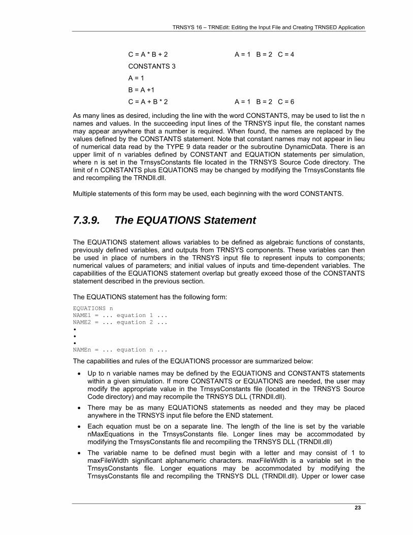
C = A * B + 2 A = 1 B = 2 C = 4
CONSTANTS 3
A = 1
B = A +1
C = A + B * 2 A = 1 B = 2 C = 6
As many lines as desired, including the line with the word CONSTANTS, may be used to list the n names and values. In the succeeding input lines of the TRNSYS input file, the constant names may appear anywhere that a number is required. When found, the names are replaced by the values defined by the CONSTANTS statement. Note that constant names may not appear in lieu of numerical data read by the TYPE 9 data reader or the subroutine DynamicData. There is an upper limit of n variables defined by CONSTANT and EQUATION statements per simulation, where n is set in the TrnsysConstants file located in the TRNSYS Source Code directory. The limit of n CONSTANTS plus EQUATIONS may be changed by modifying the TrnsysConstants file and recompiling the TRNDll.dll.
Multiple statements of this form may be used, each beginning with the word CONSTANTS.
7.3.9. The EQUATIONS Statement
The EQUATIONS statement allows variables to be defined as algebraic functions of constants, previously defined variables, and outputs from TRNSYS components. These variables can then be used in place of numbers in the TRNSYS input file to represent inputs to components; numerical values of parameters; and initial values of inputs and time-dependent variables. The capabilities of the EQUATIONS statement overlap but greatly exceed those of the CONSTANTS statement described in the previous section.
The EQUATIONS statement has the following form: EQUATIONS n NAME1 = ... equation 1 ... NAME2 = ... equation 2 ... • • • NAMEn = ... equation n ...
The capabilities and rules of the EQUATIONS processor are summarized below:
• Up to n variable names may be defined by the EQUATIONS and CONSTANTS statements within a given simulation. If more CONSTANTS or EQUATIONS are needed, the user may modify the appropriate value in the TrnsysConstants file (located in the TRNSYS Source Code directory) and may recompile the TRNSYS DLL (TRNDll.dll).
• There may be as many EQUATIONS statements as needed and they may be placed anywhere in the TRNSYS input file before the END statement.
• Each equation must be on a separate line. The length of the line is set by the variable nMaxEquations in the TrnsysConstants file. Longer lines may be accommodated by modifying the TrnsysConstants file and recompiling the TRNSYS DLL (TRNDll.dll)
• The variable name to be defined must begin with a letter and may consist of 1 to maxFileWidth significant alphanumeric characters. maxFileWidth is a variable set in the TrnsysConstants file. Longer equations may be accommodated by modifying the TrnsysConstants file and recompiling the TRNSYS DLL (TRNDll.dll). Upper or lower case
TRNSYS 16 – TRNEdit: Editing the Input File and Creating TRNSED Application
24�
letters may be used in the input file, but all letters are internally converted to upper case. The variable name must not have been previously defined by either preceding EQUATIONS or by a CONSTANTS statement. Certain names are reserved for built-in functions, such as TIME, sin, max, etc. A list of the available functions appears in item 9 of this list.
• Spaces may appear anywhere in the equation for readability, except within variable names. • The variable being defined must be followed by an equal sign. Only one equal sign may
appear in an equation. • The algebraic expression to the right of the equal sign may involve numerical values,
variable names defined with EQUATIONS or CONSTANTS statements elsewhere in the input file or outputs from TRNSYS components. TRNSYS outputs are referenced by placing the unit and output numbers in square brackets separated by a comma or space. Thus [5,3] refers to the third output of UNIT 5.
• Equations are formulated using exactly the same rules as used in FORTRAN. Parentheses may be used as needed. Either ** or ^ may be used to denote raising to a power.
7.3.9.1. Available mathematical functions
The EQUATIONS processor recognizes the following functions. A colon “:” is used to denote an argument. These function names are reserved and may not be used as variable names.
• AE( : , : , : ) returns 1 if the difference between the first and second arguments is less than the value of the third argument.
• ABS( : ) absolute value of the expression in parenthesis. • ACOS( : ) arc cosine of the expression in parentheses, returned in degrees. • AND( : , : ) returns Boolean AND value of expressions (separated by a comma) in
parentheses. • ASIN( : ) arc sine of the expression in parentheses, returned in degrees. • ATAN( : ) arc tangent of the expression in parentheses, returned in degrees. • COS( : ) cosine of the expression in degrees enclosed in the parentheses. • EQL( : , : ) returns 1 if first expression is equal to second; returns 0 otherwise.
(Expressions separated by a comma.) • EXP( : ) exponential of the expression enclosed in parentheses. • GT( : , : ) returns 1 if first expression in parentheses is greater than second;
returns 0 otherwise. (Expressions separated by a comma.) • INT( : ) integer value of the expression in parentheses. This function will
truncate the real value. To round up, add 0.5 to the expression. • OR( : , : ) returns Boolean OR value of expressions (separated by a comma) in
parentheses. • LN( : ) base e logarithm of the expression enclosed in parentheses. • LOG( : ) base 10 logarithm of the expression enclosed in parentheses. • LT( : , : ) returns 1 if first expression in parentheses is less than second; returns 0
otherwise. (Expressions separated by a comma.) • MAX( : , : ) maximum of the two expressions, separated by a comma, in the
parentheses. • MIN( : , : ) minimum of the two expressions, separated by a comma, in the
parentheses. • MOD( : , : ) modulus, i.e., the remainder of the division of the first expression by the
second expression. A repeating daily function can be generated by
TRNSYS 16 – TRNEdit: Editing the Input File and Creating TRNSED Application
25�
taking the modulus of time with a 24 hour period, e.g., REPEAT = 7+MOD(TIME,24).
• NOT( : ) returns Boolean NOT value of expression in parentheses. • SIN( : ) sine of the expression in degrees enclosed in the parentheses. • TAN( : ) tangent of the expression in degrees enclosed in the parentheses. • The following variables have predefined values and may not be redefined: • CONST indicates 'constant' and may be used interchangeably with [0,0] as the unit and
output numbers specifying a constant INPUT. (See section 7.4.3). • TIME current time in the simulation.
Variable names defined by an EQUATIONS or CONSTANTS statement may be used in place of numerical values or the unit number, output number combinations which follow the INPUTS statement. Variables used as INPUTS are evaluated each time one of their constituent quantities changes. Variables used in place of numerical values for parameters, or initial values of inputs and time-dependent quantities are evaluated once at the start of the simulation and therefore should not refer to TIME or to component outputs. Important: Equations that vary with time should not be used as initial values or as parameters since the equation will be calculated only once at the beginning of the simulation.
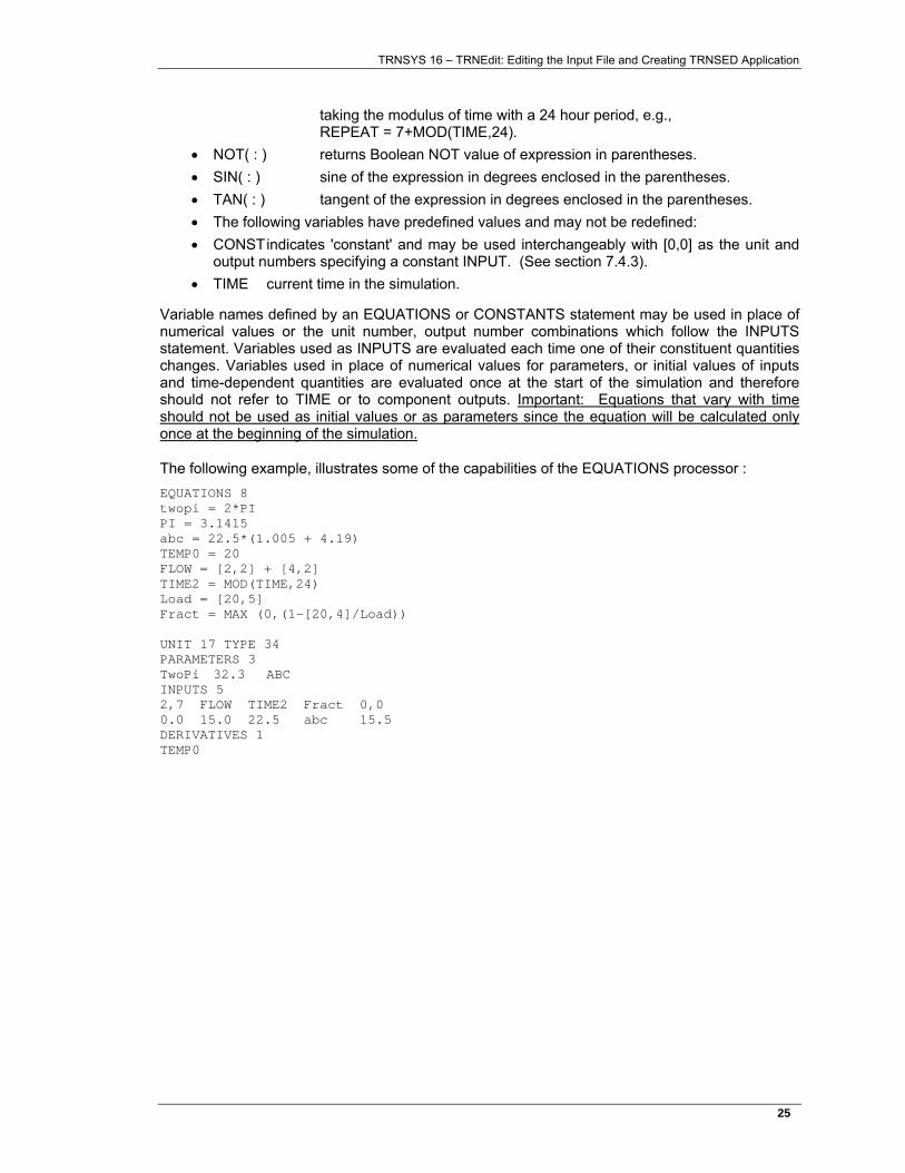
The following example, illustrates some of the capabilities of the EQUATIONS processor : EQUATIONS 8 twopi = 2*PI PI = 3.1415 abc = 22.5*(1.005 + 4.19) TEMP0 = 20 FLOW = [2,2] + [4,2] TIME2 = MOD(TIME,24) Load = [20,5] Fract = MAX (0,(1-[20,4]/Load)) UNIT 17 TYPE 34 PARAMETERS 3 TwoPi 32.3 ABC INPUTS 5 2,7 FLOW TIME2 Fract 0,0 0.0 15.0 22.5 abc 15.5 DERIVATIVES 1 TEMP0
TRNSYS 16 – TRNEdit: Editing the Input File and Creating TRNSED Application
26�
7.3.9.2. Additional checking functions
The following set of functions may be used to provide another level of error checking when users are specifying detailed systems.
EQWARN( , , )
returns 1 if first expression in parentheses is equal to the second. Otherwise, it returns 0 and writes an error message.
GTWARN( , , )
returns 1 if first expression in parentheses is greater than second. Otherwise, it returns 0 and writes an error message.
GEWARN( , , )
returns 1 if first expression in parentheses is greater than or equal to the second; Otherwise, it returns 0 and writes an error message.
NEWARN( , , )
returns 1 if first expression in parentheses is not equal to the second. Otherwise, it returns 0 and writes an error message.
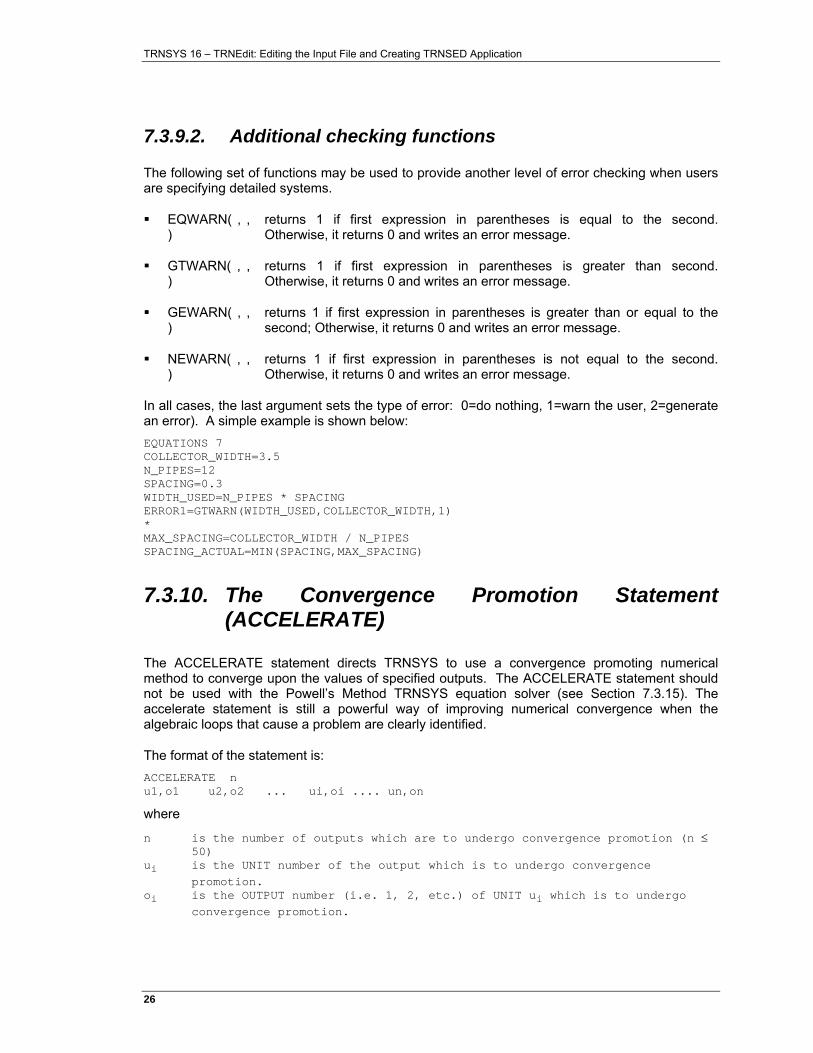
In all cases, the last argument sets the type of error: 0=do nothing, 1=warn the user, 2=generate an error). A simple example is shown below: EQUATIONS 7 COLLECTOR_WIDTH=3.5 N_PIPES=12 SPACING=0.3 WIDTH_USED=N_PIPES * SPACING ERROR1=GTWARN(WIDTH_USED,COLLECTOR_WIDTH,1) * MAX_SPACING=COLLECTOR_WIDTH / N_PIPES SPACING_ACTUAL=MIN(SPACING,MAX_SPACING)
7.3.10. The Convergence Promotion Statement (ACCELERATE)
The ACCELERATE statement directs TRNSYS to use a convergence promoting numerical method to converge upon the values of specified outputs. The ACCELERATE statement should not be used with the Powell’s Method TRNSYS equation solver (see Section 7.3.15). The accelerate statement is still a powerful way of improving numerical convergence when the algebraic loops that cause a problem are clearly identified.
The format of the statement is: ACCELERATE n u1,o1 u2,o2 ... ui,oi .... un,on
where
n is the number of outputs which are to undergo convergence promotion (n ≤ 50)
ui is the UNIT number of the output which is to undergo convergence promotion.
oi is the OUTPUT number (i.e. 1, 2, etc.) of UNIT ui which is to undergo convergence promotion.
TRNSYS 16 – TRNEdit: Editing the Input File and Creating TRNSED Application
27�
Only 1 ACCELERATE statement is allowed: A maximum of 50 outputs to be accelerated may be specified. The ACCELERATE statement may be placed anywhere between the SIMULATION and END statements in the TRNSYS input file.
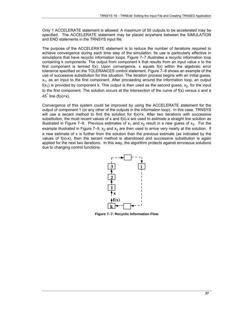
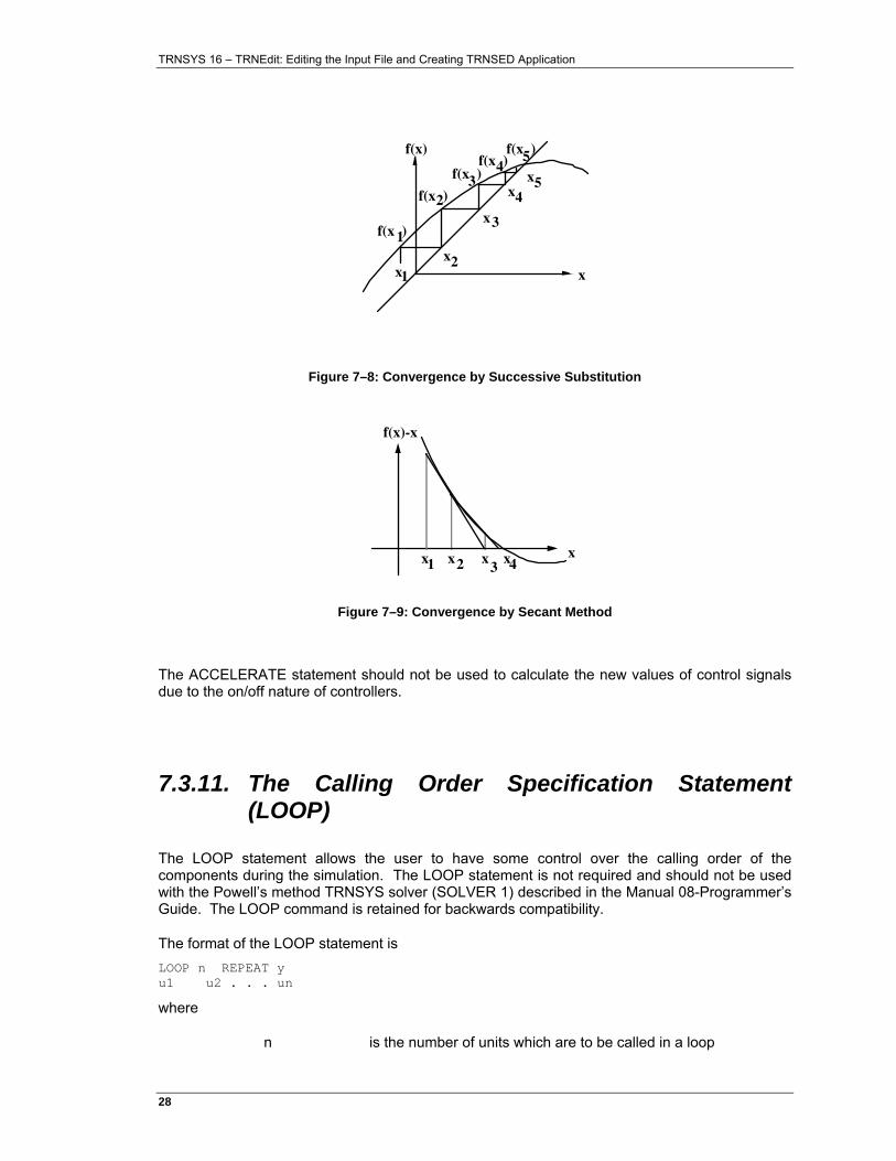
The purpose of the ACCELERATE statement is to reduce the number of iterations required to achieve convergence during each time step of the simulation. Its use is particularly effective in simulations that have recyclic information loops. Figure 7–7 illustrates a recyclic information loop containing k components. The output from component k that results from an input value x to the first component is termed f(x). Upon convergence, x equals f(x) within the algebraic error tolerance specified on the TOLERANCES control statement. Figure 7–8 shows an example of the use of successive substitution for this situation. The iteration process begins with an initial guess, x1, as an input to the first component. After proceeding around the information loop, an output f(x1) is provided by component k. This output is then used as the second guess, x2, for the input to the first component. The solution occurs at the intersection of the curve of f(x) versus x and a 45° line (f(x)=x).
Convergence of this system could be improved by using the ACCELERATE statement for the output of component 1 (or any other of the outputs in the information loop). In this case, TRNSYS will use a secant method to find the solution for f(x)=x. After two iterations with successive substitution, the most recent values of x and f(x)-x are used to estimate a straight line solution as illustrated in Figure 7–9. Previous estimates of x1 and x2 result in a new guess of x3. For the example illustrated in Figure 7–9, x2 and x3 are then used to arrive very nearly at the solution. If a new estimate of x is further from the solution than the previous estimate (as indicated by the values of f(x)-x), then the secant method is abandoned and successive substitution is again applied for the next two iterations. In this way, the algorithm protects against erroneous solutions due to changing control functions.
k
1
2
3 i
xf(x)
Figure 7–7: Recyclic Information Flow
TRNSYS 16 – TRNEdit: Editing the Input File and Creating TRNSED Application
28�
1
2
x1x2
x3
x4x5
f(x )
f(x )
f(x )f(x )
f(x )
34
5
x
f(x)
Figure 7–8: Convergence by Successive Substitution
x1 x2 x3
x4x
f(x)-x
Figure 7–9: Convergence by Secant Method
The ACCELERATE statement should not be used to calculate the new values of control signals due to the on/off nature of controllers.
7.3.11. The Calling Order Specification Statement (LOOP)
The LOOP statement allows the user to have some control over the calling order of the components during the simulation. The LOOP statement is not required and should not be used with the Powell’s method TRNSYS solver (SOLVER 1) described in the Manual 08-Programmer’s Guide. The LOOP command is retained for backwards compatibility.
The format of the LOOP statement is LOOP n REPEAT y u1 u2 . . . un
where
n is the number of units which are to be called in a loop
TRNSYS 16 – TRNEdit: Editing the Input File and Creating TRNSED Application
29�
y is the number of times these units will be called (if convergence is not attained)
ui is the UNIT number for unit i
Up to 10 LOOP statements may appear in the TRNSYS input file and they may be placed anywhere after the SIMULATION statement and before the END statement. A grand total of 250 units may be listed on the 10 statements.
TRNSYS iteratively calls only the component subroutines whose INPUTS have not converged or whose OUTPUTS depend explicitly upon simulation time, as indicated either by the existence of derivatives (INFO(5)>0) or other time function (INFO(9)=1) (See Volume 08, Programmer’s Guide). If a LOOP statement does not appear in the TRNSYS input file, the order in which the units are called is the same as the order in which they appear in the TRNSYS input file with some exceptione (see the role of the INFO array in volume 08, Programmer’s Guide).
The calculation order may be changed to some extent by simply rearranging the order of the components in the input file. The most efficient calculation scheme appears to be one in which the order is the same as the direction of information flow. Although the order in which the units are called should not affect the results of the simulation, it may affect the amount of calculation required. TRNSYS summarizes the number of times each UNIT was called at the end of the simulation output.
In some simulations, particularly those with multiple recyclic information flow loops, it may be advantageous to call some units several times, thereby allowing them to partially converge upon a local solution, before remaining units in the simulation input file are called. Control of this type is possible with the LOOP statement. The LOOP statement indicates to TRNSYS that the n specified units are to be called after the UNIT preceding the LOOP statement in the input file for up to y times.
The operation of the LOOP statement is best explained by a simple example: Consider a TRNSYS input file containing the following UNIT and LOOP statements in the indicated order. UNIT 1 TYPE 12 . . . UNIT 5 TYPE 13 . . . UNIT 2 TYPE 14 . . . LOOP 3 REPEAT 2 1 3 2 UNIT 3 TYPE 36 . . . UNIT 7 TYPE 37 . . .
Without the LOOP statement, TRNSYS checks the inputs to, and if necessary calls, units 1, 5, 2, 3, 7 repeatedly in this order until convergence within the specified tolerance is attained. With the LOOP statement, the calling order during each iteration is: 1, 5, 2, 1, 3, 2, 1, 3, 2, 3, 7. Although
TRNSYS 16 – TRNEdit: Editing the Input File and Creating TRNSED Application
30�
the calling order is changed, TRNSYS will only call a unit if its inputs do not match within tolerance with values from the previous call.
7.3.12. The Differential Equation Solving Method Statement (DFQ)
The optional DFQ card allows the user to select one of three algorithms built into TRNSYS to numerically solve differential equations (see Manual 08-Programmer’s Guide for additional information about solution of differential equations).
The format of the DFQ card is DFQ k
where k is an integer between 1 and 3. If a DFQ card is not present in the TRNSYS input file, DFQ 1 is assumed.
The three numerical integration algorithms are:
1. Modified-Euler method (a 2nd order Runge-Kutta method)
2. Non-self-starting Heun's method (a 2nd order Predictor-Corrector method)
3. Fourth-order Adams method (a 4th order Predictor-Corrector method)
Descriptions of these algorithms can be found in (Chapra and Canale, 1985) and most other numerical methods books.
All three algorithms have been chosen to allow TRNSYS to simultaneously solve the algebraic and differential equations comprising the system model each time step. Although it would appear that higher order methods, such as the 4th order predictor-corrector method, would result in improved accuracy and reduced computation, this is not generally the case in TRNSYS simulations because of the need to simultaneously solve algebraic and differential equations. Experience has shown that Heun's method usually is most efficient, however the modified Euler method is most consistent with the analytical method of solving differential equations used in many components (see Manual 08-Programmer’s Guide for additional information about solution of differential equations).
7.3.13. The Convergence Check Suppression Statement (NOCHECK)
TRNSYS allows up to 20 different INPUTS to be removed from the list of INPUTS to be checked for convergence (see Section 1.9). This is done using the NOCHECK statement, which has the following format: NOCHECK n u1,i1 u2,i2 . . . ui,ii . . . un,in
where
n is the number of inputs which are to bypass the convergence checking (n ≤ 20).
TRNSYS 16 – TRNEdit: Editing the Input File and Creating TRNSED Application
31�
ui is the UNIT number of the input which is to be bypassed in convergence checking.
ii is the INPUT number (i.e. 1, 2, etc.) of UNIT ui which is to be bypassed in convergence checking.
Only 1 NOCHECK statement is allowed and it may be placed anywhere before the END statement.
The NOCHECK statement replaces the convergence check inhibiting feature documented in earlier versions of TRNSYS. Placing a negative sign before a unit, output pair in an input specification will not inhibit convergence checking (and will, in fact, cause an error). The NOCHECK statement must be used instead.
This NOCHECK statement should be used with extreme caution since it inhibits the fundamental error checking functions of the TRNSYS processor and can result in unpredictable and incorrect results if it is applied without a careful analysis of the system's information flow. The following discussion concerns a situation in which this option could be applied with good results.
Certain types of simulations require that components have as inputs both temperatures and energy flows. An example is a house space heating system in which tank or rockbed energy losses are added to the heated space. The house model (TYPE 12 or TYPE 19) would also require as inputs the temperature and mass flow rate of fluid out of the storage unit. Since TRNSYS applies the algebraic convergence test to INPUTS of components, in this case fluid temperature, mass flow rate, and heat losses which are input to the room model will be checked for convergence. If relative convergence test using default tolerances is applied to all inputs, and, for example, the storage unit temperature is around 100 degrees, a variation of less than one degree in storage unit outlet temperature will satisfy the convergence test, since this is less than 1% of the magnitude of the input value. Storage losses may be on the order of 3000 and will have to vary by less than 30 from one call to the next for convergence to be obtained. If the storage fluid flow rate is high, a variation of 1 degree in house inlet temperature may represent a large change in delivered energy. Under these circumstances, default error tolerances will probably result in poor energy balances.
The solution to the energy balance problem is to use absolute error tolerances in the simulation. This could be done by inserting a "TOLERANCES -0.1, -0.1" statement into the simulation input file. With these specified tolerances, the INPUTS to units will have to change by less than 0.1 in magnitude before TRNSYS assumes that algebraic convergence has been obtained. This is a reasonable requirement for the storage fluid temperature input to the house, since it is on the order of 100. However, the storage unit energy losses are much larger and are sensitive to changes in house and storage unit temperature. As a result, iteration may continue far beyond the point required for convergence of the linked temperatures due to the sensitivity of storage losses to slight variations in system temperatures. A situation like this will result in a slow and expensive simulation run.
This leaves a TRNSYS user with two equally undesirable alternatives. The first is to use default (relative) error tolerances and have poor energy balances. The second is to exclude storage unit energy losses from the house model and use absolute error tolerances. Neither alternative will give an accurate picture of system thermal performance. A way around this problem is to use absolute error tolerances to get good energy balances and to prevent TRNSYS from checking the tank loss input of the house model for convergence using the NOCHECK statement.
The NOCHECK statement takes on additional importance when the TRNSYS Powell’s Method solver is employed; especially when backsolving is to be used. When using the Powell’s Method TRNSYS solver, control signals and other specific TRNSYS input types should not be checked. The solver section (7.3.14) provides more information.
TRNSYS 16 – TRNEdit: Editing the Input File and Creating TRNSED Application
32�
7.3.14. The Equation Solving Method Statement (EQSOLVER)
With the release of TRNSYS 16, new methods for solving blocks of EQUATIONS statements were added. For additional information on EQUATIONS statements, please refer to section 7.3.9. The order in which blocks of EQUATIONS are solved is controlled by the EQSOLVER statement. The syntax of the command is as follows: EQSOLVER n
Where n can have any of the following values:
n=0 (default if no value is provided) if a component output or TIME changes, update the block of equations that depend upon those values. Then update components that depend upon the first block of equations. Continue looping until all equations have been updated appropriately. This equation blocking method is most like the method used in TRNSYS version 15 and before.
n=1 if a component output or TIME changes by more than the value set in the TOLERANCES Statement (see Section 7.3.3), update the block of equations that depend upon those values. Then update components that depend upon the first block of equations. Continue looping until all equations have been updated appropriately.
n=2 treat equations as a component and update them only after updating all components.
7.3.15. The SOLVER Statement
TRNSYS is outfitted with two methods for solving the coupled system of algebraic and differential equations that model a given system: the “successive substitution” method and “Powell’s” method.
A SOLVER command has been added to TRNSYS to select the computational scheme. The optional SOLVER card allows the user to select one of two algorithms built into TRNSYS to numerically solve the system of algebraic and differential equations. The format of the SOLVER card is SOLVER k
where k is either the integer 0 or 1. If a SOLVER card is not present in the TRNSYS input file, SOLVER 0 is assumed. If k = 0, the SOLVER statement takes two additional parameters, RFmin and RFmax (see section ): SOLVER 0 RFmin RFmax
The two solution algorithms are:
• 0: Successive Substitution • 1: Powell’s Method (Powell, 1970a and 1070b)
Descriptions of these algorithms can be found in the references and most other numerical methods books. They are briefly described in the next sections.
TRNSYS 16 – TRNEdit: Editing the Input File and Creating TRNSED Application
33�
7.3.15.1. Solver 0: Successive substitution
With successive substitution, the outputs of a given model are substituted for the inputs of the next model in the system. The performance of that next model is recomputed and its outputs are then substituted for the inputs of the next model. This substitution continues at a given time step until all connected outputs have stopped changing (i.e. their change is smaller than the limits fixed by the TOLERANCES statement). At that point the TRNSYS kernel deems that convergence has been reached and proceeds on to simulate the next time step.
Generally speaking, TRNSYS calls all components at least once per time step. Then, the TRNSYS solver keeps track of which components must be called during the same time step: only components for which at least one input has changed beyond the fixed tolerances are called. When all components have converged, or when the maximum number of iterations has been reached (see the LIMITS statement), TRNSYS continues to the next time step.
Note: Some components have a different behavior, depending on their value of INFO(9). For example, printers are not part of the normal iterative process, they are only called after all other components have converged. Please see Volume 08, Programmer's Guide, for more details.
Although relatively simple, the successive substitution computational scheme used in most TRNSYS simulations has proven to be reliable and efficient for simulating systems with energy storage such as solar domestic hot water systems, buildings, and HVAC systems. These systems typically have less than 50 coupled differential equations and 100 simultaneous nearly-linear algebraic equations with few recyclic loops and controller decisions. The limitations of the computational scheme become apparent when TRNSYS is used to solve sets of non-linear algebraic equations without differential equations. Equations of this type occur in systems for which the energy storage is negligible, such as for a photovoltaic array directly coupled to a load or a refrigeration system operating at steady-state conditions. The successive substitution solution method does not efficiently solve non-linear algebraic equations and may, in fact, not be able to find a solution if the equations are highly non-linear. If the algebraic loops that cause the numerical problems are clearly identified, the ACCELERATE statement can be used to solve the problem. In other cases, adding numerical relaxation to solver 0 can improve its robustness and speed, depending on the type of numerical problems which is involved. Both methods are described here below
THE ACCELERATE STATEMENT
An ACCELERATE command was added to TRNSYS version 13 to improve convergence in problems with recyclic information flow. The ACCELERATE (see Section 7.3.10) command allows the user to break a selected INPUT-OUTPUT connection and replace it with a single-variable Newton’s method solution algorithm. Although useful in many circumstances, the ACCELERATE command may be unsatisfactory for two reasons; 1) it requires the user to identify the appropriate INPUT-OUTPUT connection and 2) it implements a single-variable solution method when in many situations, a multiple-variable method is required. Another way in which numerical convergence problems have been handled in past versions is by the user coding convergence-enhancing techniques within the component models. For example, ‘combined-component’ models have been developed for TRNSYS wherein the non-linear equations describing two or more pieces of equipment are solved internally in a single component model. Although ‘combined-component’ models may eliminate numerical problems, they reduce component modularity and require the user to implement solution techniques, thereby defeating the original purpose of TRNSYS.
NUMERICAL RELAXATION
TRNSYS 16 – TRNEdit: Editing the Input File and Creating TRNSED Application
34�
Numerical relaxation has been proven to significantly improve the performance of TRNSYS solver 0 for some classes of problems. The coupling of airflow and temperatures in a building are a typical example of problems that cannot be solved easily using successive substitution, and the implementation of numerical relaxation in the TRNSYS kernel was decided after its successful application in TRNFLOW (Weber et al., 2003).
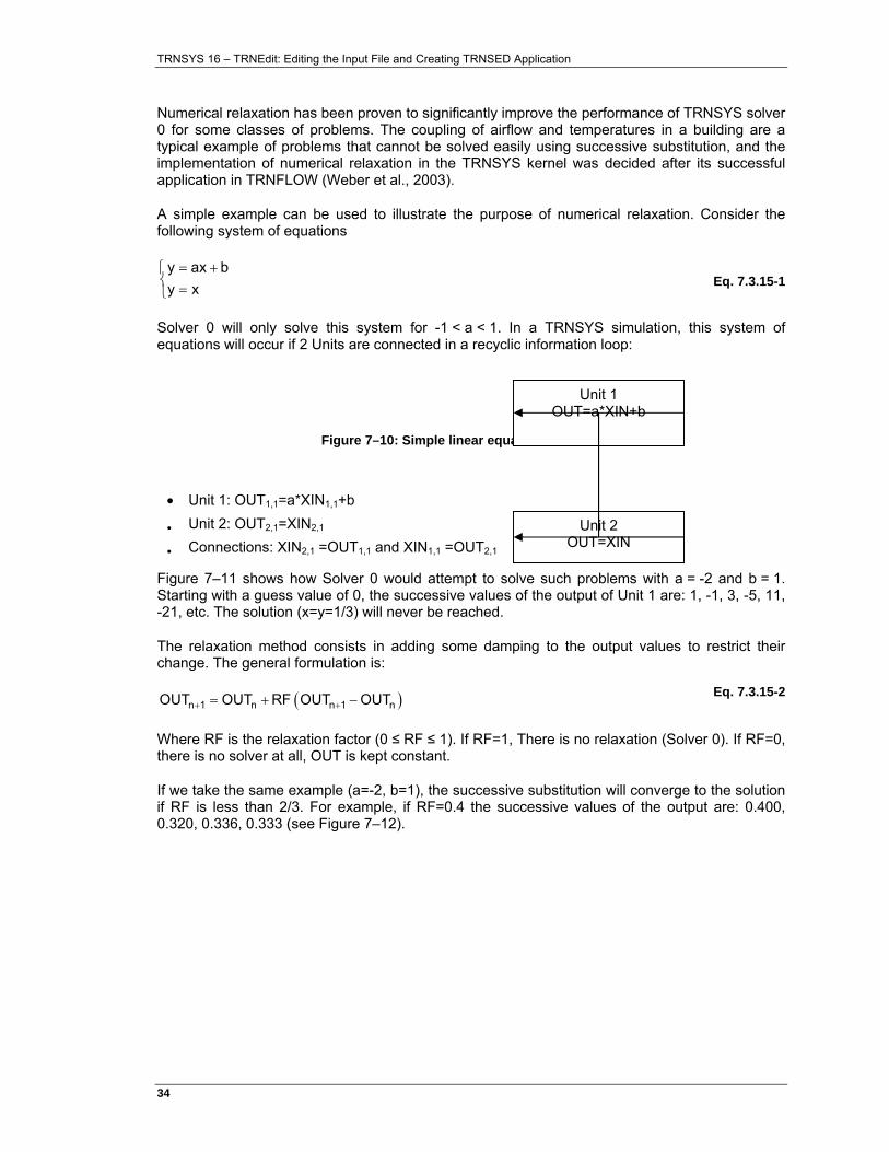
A simple example can be used to illustrate the purpose of numerical relaxation. Consider the following system of equations
= +⎧⎨ =⎩
y ax by x
Eq. 7.3.15-1
Solver 0 will only solve this system for -1 < a < 1. In a TRNSYS simulation, this system of equations will occur if 2 Units are connected in a recyclic information loop:
Figure 7–10: Simple linear equations in TRNSYS
• Unit 1: OUT1,1=a*XIN1,1+b
• Unit 2: OUT2,1=XIN2,1
• Connections: XIN2,1 =OUT1,1 and XIN1,1 =OUT2,1
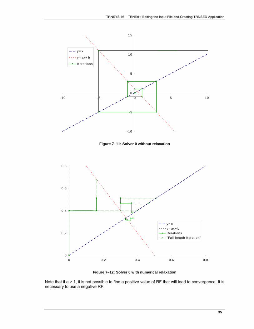
Figure 7–11 shows how Solver 0 would attempt to solve such problems with a = -2 and b = 1. Starting with a guess value of 0, the successive values of the output of Unit 1 are: 1, -1, 3, -5, 11, -21, etc. The solution (x=y=1/3) will never be reached.
The relaxation method consists in adding some damping to the output values to restrict their change. The general formulation is:
( )+ += + −n 1 n n 1 nOUT OUT RF OUT OUT Eq. 7.3.15-2
Where RF is the relaxation factor (0 ≤ RF ≤ 1). If RF=1, There is no relaxation (Solver 0). If RF=0, there is no solver at all, OUT is kept constant.
If we take the same example (a=-2, b=1), the successive substitution will converge to the solution if RF is less than 2/3. For example, if RF=0.4 the successive values of the output are: 0.400, 0.320, 0.336, 0.333 (see Figure 7–12).
Unit 1 OUT=a*XIN+b
Unit 2 OUT=XIN
TRNSYS 16 – TRNEdit: Editing the Input File and Creating TRNSED Application
35�
-10
-5
0
5
10
15
-10 -5 0 5 10
y=x
y=ax+b
Iterations
Figure 7–11: Solver 0 without relaxation
0
0.2
0.4
0.6
0.8
0 0.2 0.4 0.6 0.8
y=xy=ax+bIterations"Full length iteration"
Figure 7–12: Solver 0 with numerical relaxation
Note that if a > 1, it is not possible to find a positive value of RF that will lead to convergence. It is necessary to use a negative RF.
TRNSYS 16 – TRNEdit: Editing the Input File and Creating TRNSED Application
36�
IMPLEMENTATION OF THE RELAXATION IN TRNSYS
The relaxation factor is chosen for each output independently and then the output is modified according to.
The implemented rules to modify the relaxation factor were proposed by EMPA:
( ) ( )( )+ −
+
+
− − <
=
=
⎡ ⎤⎣ ⎦
n 1 n n n 1
nn 1
n 1 n
min max
If OUT OUT OUT OUT 0
RFRF
2Else
RF 1.5 RFIn all cases, RF is restricted to RF ; RF
Eq. 7.3.15-3
In other words, the relaxation factor is reduced (*0.5) when the solution oscillates and it is increased (*1.5) when the solution keeps progressing in the same direction.
7.3.15.2. Solver 1: Powell's method
Two reasons led to the development of Solver 1: the need for backsolving and the oscillations resulting from discrete controller outputs.
Notes:
Backsolving requires all TRNSYS components used in a simulation to comply with certain rules, which is rarely the case. For this reason, this feature should be considered for research applications only.
Discrete-state controllers should also be adapted to use solver 1. An example is given by Type 2, the ON-OFF controller with hysteresis. Users are invited to use Type 2 as a template if they want to develop controllers for solver 1. It is important to note that a mismatch between the selected solver and the one that is expected by the component will lead to unpredictable results (hence the error message generated by Type 2). It is generally recommended to use Solver 0 (without and with numerical relaxation) and to consider reduced time steps and time delays before switching to Solver 1.
BACKSOLVING AND DISCRETE VARIABLES IN TRNSYS
The distinction between INPUTS and OUTPUTS in TRNSYS places a limitation on the generality of the component models. When a model is formulated, a decision must be made as to what are the INPUTS and what are the OUTPUTS. For example, a model may be developed to calculate an energy flow for a given mass flow rate and temperatures. However, in a different application, the energy flow rate may be known and the model must calculate the mass flow rate. The same physical model is used in either situation, but the INPUTS and OUTPUTS are different. Normally, TRNSYS requires different component models (or modes) to handle the change in information flow. However, the Powell’s Method solver, when implemented, is able to backsolve the TRNSYS equations; effectively solving an input for a given output as discussed below.
TRNSYS 16 – TRNEdit: Editing the Input File and Creating TRNSED Application
37�
The equations within any TRNSYS component model can be reduced to the following general form:
( )=& &i i i i iX D X ,X ,U ,t Eq. 7.3.15-4
( )=&i i iX F U ,t Eq. 7.3.15-5
where Ui and Xi are, respectively, the vector of INPUTS and OUTPUTS for the ith module, t is time, and Di and Fi are functions representing the differential and algebraic equations, respectively.
An analogous set of equations can be written for the combined set of equations in all components,
( )=& &X D X,X,U,t Eq. 7.3.15-6
( )=&X F U,t Eq. 7.3.15-7
where U and X are vectors containing the INPUTS and OUTPUTS for all components. Each INPUT in a TRNSYS model is an OUTPUT from another component, an equation, or a specified value. This additional information can be written as a matrix equation:
AU + BX + D = 0 Eq. 7.3.15-8
where A and B are coupling matrixes with element values of 0 and ±1, and D is a vector of boundary conditions. The system of algebraic-differential equations can now be solved to determine U(t) and X(t).
The number of simultaneous non-linear equations resulting from this new computational scheme can become very large. To minimize computational effort, it is necessary to employ methods for decreasing the number of simultaneous equations. Some TRNSYS inputs are always known, either because they are constants or they depend explicitly on time. Moreover, it is possible for all of the inputs in some TRNSYS components to be of this type. In this case, the outputs of these components can be calculated independently of other components. Once the outputs of these components are known, the inputs to which they are connected are now known, possibly allowing additional components to be evaluated independently. This process is repeated until only the components that require simultaneous solution remain. This process is a first step in equation blocking in which a large set of equations is broken into smaller sets that are more easily solved.
The remaining set of equations is solved numerically. There are a number of well-developed numerical methods for these types of systems (Broyden, 1965; Gerald and Wheatley, 1984). In TRNSYS 14 and beyond, differential equations are solved by a backwards differential method (Gear, 1967) so that the combined algebraic and differential systems can be converted to an algebraic system which can be solved at each time step. This method is extremely robust, even for stiff problems. In addition, this method allows use of variable time steps, although TRNSYS does not currently employ variable time steps. Before solving the resulting system of algebraic equations, TRNSYS numerically calculates the Jacobian matrix and permutes it to lower triangular form. This permutation facilitates equation blocking which breaks the original system into smaller sets of equations that can be solved more efficiently (Duff et al., 1986). Each block of equations is solved using Powell's method (Powell, 1970a and 1970b). This method combines Newton's method and steepest descent approach and is one of the more robust and efficient algorithms for solving non-linear equations.
TRNSYS 16 – TRNEdit: Editing the Input File and Creating TRNSED Application
38�
A major advantage of the computational scheme is that the solution method does not care whether INPUTS or OUTPUTS are specified as long as a valid set of simultaneous equations are defined. As a result, TRNSYS has the ability to solve backward problems, i.e problems in which one or more OUTPUTS are specified and the corresponding INPUTS must be determined. An example of a backward solution problem is provided in the Examples section.
Unfortunately, there is also a disadvantage of the Powell’s method computational scheme. Because the alternative solver determines the Jacobian matrix numerically, TRNSYS usually requires more component calls each time step than the scheme used in TRNSYS 13 - provided that TRNSYS 13 is able to solve the problem. The computational scheme in TRNSYS 14 and above is far more robust and is consequently able to solve a greater variety of problems without experiencing computational difficulties. However, because some problems can be more efficiently solved with the successive substitution computational scheme, both computational schemes are made available to the user in TRNSYS version 14 and above. In most cases, users should try to solve their TRNSYS input file using the simpler (and most times quicker) successive substitution method. If problems are encountered, the alternative solver should be employed.
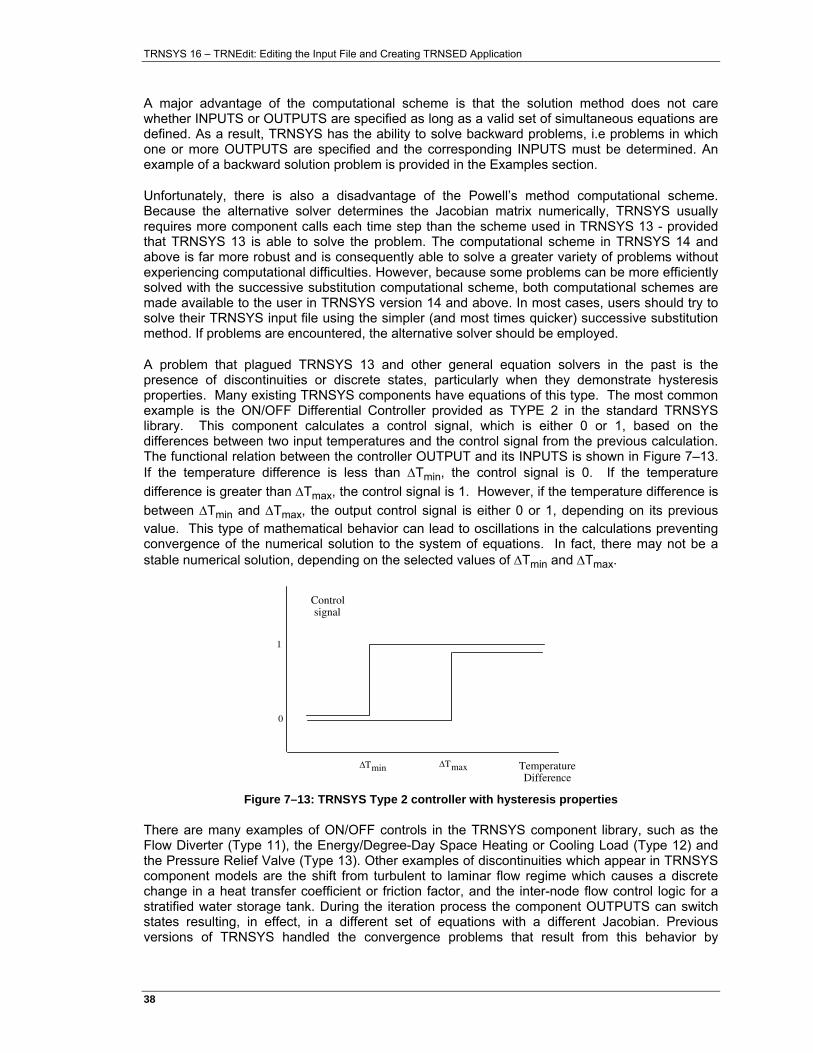
A problem that plagued TRNSYS 13 and other general equation solvers in the past is the presence of discontinuities or discrete states, particularly when they demonstrate hysteresis properties. Many existing TRNSYS components have equations of this type. The most common example is the ON/OFF Differential Controller provided as TYPE 2 in the standard TRNSYS library. This component calculates a control signal, which is either 0 or 1, based on the differences between two input temperatures and the control signal from the previous calculation. The functional relation between the controller OUTPUT and its INPUTS is shown in Figure 7–13. If the temperature difference is less than ∆Tmin, the control signal is 0. If the temperature difference is greater than ∆Tmax, the control signal is 1. However, if the temperature difference is between ∆Tmin and ∆Tmax, the output control signal is either 0 or 1, depending on its previous value. This type of mathematical behavior can lead to oscillations in the calculations preventing convergence of the numerical solution to the system of equations. In fact, there may not be a stable numerical solution, depending on the selected values of ∆Tmin and ∆Tmax.
∆Tmin TemperatureDifference
Controlsignal
1
0
∆Tmax
Figure 7–13: TRNSYS Type 2 controller with hysteresis properties
There are many examples of ON/OFF controls in the TRNSYS component library, such as the Flow Diverter (Type 11), the Energy/Degree-Day Space Heating or Cooling Load (Type 12) and the Pressure Relief Valve (Type 13). Other examples of discontinuities which appear in TRNSYS component models are the shift from turbulent to laminar flow regime which causes a discrete change in a heat transfer coefficient or friction factor, and the inter-node flow control logic for a stratified water storage tank. During the iteration process the component OUTPUTS can switch states resulting, in effect, in a different set of equations with a different Jacobian. Previous versions of TRNSYS handled the convergence problems that result from this behavior by
TRNSYS 16 – TRNEdit: Editing the Input File and Creating TRNSED Application
39�
‘sticking’ the state after a specified number of iterations. For example, the TYPE 2 ON/OFF Differential Controller has a parameters called NSTK which is the number of state changes allowed before the controller state is frozen at its current value. Although freezing the controller state eliminates most convergence problems, it may lead to incorrect results in some cases, particularly in short term simulations.
The Powell’s Method solver in TRNSYS 14 provided a very different approach for handling these problematic discontinuities. The TRNSYS executive program, rather than the component models, directly controls discrete variables. At the start of each time step, the values of all discrete variables are known. TRNSYS forces these values to remain at their current state until a converged solution to the equations is obtained or an iteration limit is encountered. During these calculations, the component models calculate the ‘desired’ value of the discrete variables but they do not actually change the settings. After a converged solution is obtained, or the maximum number of iterations is exceeded, TRNSYS compares the current discrete variable values with the ‘desired’ values. If they do not differ and a converged solution has been obtained, the calculations are completed for the time step. Otherwise, TRNSYS changes the values of the discrete variables to the ‘desired’ setting and repeats this process, taking care to not repeat the calculations with the same set of discrete variables used previously. If a solution is not obtained after all combinations of discrete variables have been tried, TRNSYS issues a warning message and continues on to the next time step. This method of dealing with discrete variables eliminates numerical oscillations between iterations and finds the correct solution to the equations, provided that a solution truly exists. Minor changes in the component models utilizing discrete variables are required to take advantage of this computational scheme. These changes have been made in many of the TRNSYS library components. For these reasons, the Powell’s Method mode of the Type 2 controller should be used when the Powell’s Method TRNSYS equation solver (SOLVER=1). Refer to the TYPE 2 documentation for more details.
To use the backsolving technique described in this section, follow the guidelines listed below:
1. the Powell’s Method TRNSYS equation solver should be used (SOLVER 1)
2. the Powell’s Method control mode should be used (TYPE 2 - MODE 0)
3. initial values should be reasonable and non-zero
4. the input to be solved should be specified as -1,0 in the input file with an initial value equal to the value the input will take if no backwards solution is found.
5. the specified OUTPUT should be set in an equation with the form: EQUATION 1 [5,3] = 65 (set the third output from UNIT 5 to a constant value of 65)
6. the specified OUTPUT can be of any form acceptable to the TRNSYS equation processor ( [5,3] = 65 + MOD(TIME) + 0.5 * [1,1] for example)
7. the NOCHECK statement should be used with the following variables: • all INPUTS to the TYPE 2 controllers (required to eliminate
convergence problems) • all INPUTS which do not need to be checked for convergence at each
iteration. For example flow rates at all components in a flow loop (recommended to reduce the set of equations to be solved)
8. set the differential equation solver to Modified-Euler method (DFQ 1)
Although the backsolving technique is extremely useful, in many cases it can not be employed due to the formulation of many component routines. Due to internal convergence enhancement algorithms, all users writing component routines should consider the backsolving technique during component formulation.
TRNSYS 16 – TRNEdit: Editing the Input File and Creating TRNSED Application
40�
7.3.16. The ASSIGN Statement and Logical Unit Numbers
The ASSIGN statement allows the assignment of files to logical unit numbers from within the TRNSYS input file. The format for this statement is ASSIGN filename lu
where
filename is the full name of the desired file (including path, if necessary); filename must be less than or equal to maxFileWidth characters in length. Spaces are allowed in pathnames as long as the entire path is contained in quotes. Quote marks are not necessary if there are no spaces in the pathname. MaxFileWidth is set in the TrnsysConstants file located in the TRNSYS Source Code directory. maxFileWidth may be modified and a new TRNDll.dll created if necessary. Paths may be relative to the location of the input file.
lu is the logical unit number to which filename is to be assigned
Certain other conventions and “short cuts” apply to ASSIGN statements. First, if the path or file name contains spaces, the entire path must be enclosed in double quote marks. Second, the user may replace everything in the path (excepting the file extension) with the code “***” In this case, the name and location of the input file will be appended on to the user specified file extension. For example:
The input file is located at d:\Trnsys16\MyProjects\SDHWProject\InputFile.dck
The ASSIGN statement: ASSIGN “***.out” 16
Is equivalent to writing: ASSIGN “d:\Trnsys16\MyProjects\SDHWProject\InputFile.out” 16
Third, the code “.\” may be used to append the location of the TRNSYS root directory on to the remainder of a path. For example if TRNSYS is installed on the c: drive under Program Files, the ASSIGN statement: ASSIGN “.\Weather\TMY2\Wisconsin\Madiwon_WI.tm2” 14
Is equivalent to writing: ASSIGN “c:\Program Files\Trnsys16\Weather\TMY2\Wisconsin\Madiwon_WI.tm2” 14
As many ASSIGN statements as allowed in Windows may be used in a TRNSYS input file and they may be placed anywhere before the END statement. The logical unit 6 is ASSIGNED automatically by the TRNSYS 16 kernel and is used for the list file, where information pertinent to a given simulation is written.
TRNSYS uses several logical unit numbers:
LU device or file
4 TRNSYS log file (*.log): Short version of the listing files (see here below) parsed by the simulation studio
TRNSYS 16 – TRNEdit: Editing the Input File and Creating TRNSED Application
41�
5 keyboard
6 TRNSYS listing file (*.lst): listing of input file, error messages, warnings, notices, simulation run statistics and other information.
7 UNITS.LAB
8 ASHRAE.COF (for use with TYPE 19 only)
9 TRNSYS input (Deck) file
Additionally, the user must specify logical unit numbers when configuring output components, TYPE 9, and components that need to read data files. The re-use of the above listed logical unit numbers should be avoided at all costs.
Some components, such as Type56 and TRNFLow, also use hard-coded Logical units. In general, user files should be directed to LUs greater than 30 (which is done automatically by the Simulation Studio).
For better compatibility with the TRNSYS utility program such as TRNEdit and TRNSED, the following convention should be used when ASSIGNing the output, and plot files within the input file (.dck). The output, and plot files should all have the same name as the input file. For example if the input file is called TEST.DCK and located in the \trnsys16\ test\ directory, then the following ASSIGN statements should be used and placed within the input file: ASSIGN \TRNSYS16\TEST\TEST.OUT 31 ASSIGN \TRNSYS16\TEST\TEST.PLT 32
7.3.17. The INCLUDE Statement
In certain situations it is advantageous to have part of the TRNSYS input file (for example, equations passed from another program) in a separate file and include it with an INCLUDE statement into the main file. In this way, it is possible to change items or rewrite the include file without changing the main TRNSYS input file. The syntax is: INCLUDE “c:\Program Files\Trnsys16\file.inc”
When the TRNSYS input file reader reaches this line, it opens the new file (file.inc). TRNSYS reads in any valid TRNSYS statements in this second file, closes the second file and returns to the main TRNSYS input file. TRNSYS continues reading the input file from the point of the INCLUDE statement.
The list file contains all of the statements in this file and the main input file. It is not possible to do recursive INCLUDE statements.
7.3.18. The END Statement
The END statement must be the last line of a TRNSYS input file. It signals the TRNSYS processor that no more control statements follow and that the simulation may begin. The END statement has the simple form: END

TRNSYS 16 – TRNEdit: Editing the Input File and Creating TRNSED Application
42�
7.4. Component Control Statements
A description of a modular system includes all of the information contained in the information flow diagram of the system as well as the number of INPUTS, PARAMETERS and differential equations (DERIVATIVES) employed in each component model, the type of components being used, the values of their PARAMETERS, and the initial values of their INPUTS and time-dependent variables. All of this information is conveyed to TRNSYS through the use of six component control statements, followed by required data.
The control statements are
• UNIT-TYPE • PARAMETERS • INPUTS • DERIVATIVES • TRACE • FORMAT (for certain Types only)
Each component in the system model is identified by its UNIT-TYPE statement. Following each UNIT-TYPE statement are the PARAMETERS, INPUTS and DERIVATIVES control statements (and possibly the FORMAT and TRACE statements); each followed by the supplementary data they require. The next six sections describe in detail the format of each of these control statements.
7.4.1. The UNIT-TYPE Statement
The information about each component in the system begins with a UNIT-TYPE statement, which has the following format. UNIT n TYPE m Comment
where
n is the UNIT number of the component. Allowable UNIT numbers are integers between 1 and n, where n is set in TrnsysConstants.f90 (default = 999).
m is the TYPE number of the component. Allowable TYPE numbers are integers between 1 and 999.
Comment is an optional comment. The comment is reproduced on the output but is otherwise disregarded. Its function is primarily to help the user associate the UNIT and TYPE numbers with a particular component in the system.
Every system component must have and begin with a UNIT-TYPE statement. The UNIT number specified on this statement must be unique. Two UNITS cannot share the same number.
Examples: UNIT 6 TYPE 15 EXAMPLE COMPONENT UNIT 26 TYPE 26 PLOTTER
TRNSYS 16 – TRNEdit: Editing the Input File and Creating TRNSED Application
43�
7.4.2. The PARAMETERS Statement
The PARAMETERS of a component may be specified by the PARAMETERS control statement and supplementary data following it. The PARAMETERS control statement has the following format: PARAMETERS n
where
n is the number of PARAMETERS to follow on the next line(s). Typically this is the number of parameters required by the component, but may be less if more than one PARAMETERS statement is used for a given component.
The next non-comment line in the input file must contain the values of the n PARAMETERS in their proper order. Any format is allowable; a comma or one or more blanks must separate each value. The values may be placed on more than 1 line, if necessary. These lines have the general form: V1, V2, . . . , Vi, . . . , Vn
where
Vi is the value of the ith PARAMETER, or a name defined by a CONSTANTS or EQUATIONS command
The PARAMETERS statement defines the PARAMETERS for the UNIT specified on the previous UNIT-TYPE statement. (INPUTS or DERIVATIVES statements for the given unit may precede the PARAMETERS statement.) Any number of PARAMETERS statements are allowed for each UNIT.
TRNSYS has no provision for default values. All n values of the PARAMETERS must be specified on the supplementary data lines in the order they are expected by the component model. If a component model requires no PARAMETERS, the PARAMETERS control statement and the supplementary data following it should be omitted.
Example: The TYPE 3 pump model requires 4 PARAMETERS: UNIT 1 TYPE 3 PUMP PARAMETERS 4 100. 4.19 100. 0.2
Some component descriptions require a large number of parameters that are logically organized as separate lists. This is the case for the TYPE 19 Zone and TYPE 40 microprocessor components. In this situation, it is advantageous to utilize more than one PARAMETERS statements for one component description. As always, a data line (or lines) containing the number of values specified by the PARAMETERS statement must follow each PARAMETERS statement line. UNIT 1 TYPE 4 TANK PARAMETERS 3 2 .42 4.19 PARAMETERS 3 1000 1.44 -1.69
Internal limits in the TRNSYS code restrict the number of parameters/unit and the number of parameters/simulation. These values, however can be reset in the TrnsysConstants file (located in the TRNSYS Source Code directory. Modification of the values requires recompilation of the TRNSYS DLL in order for the changes to take effect.
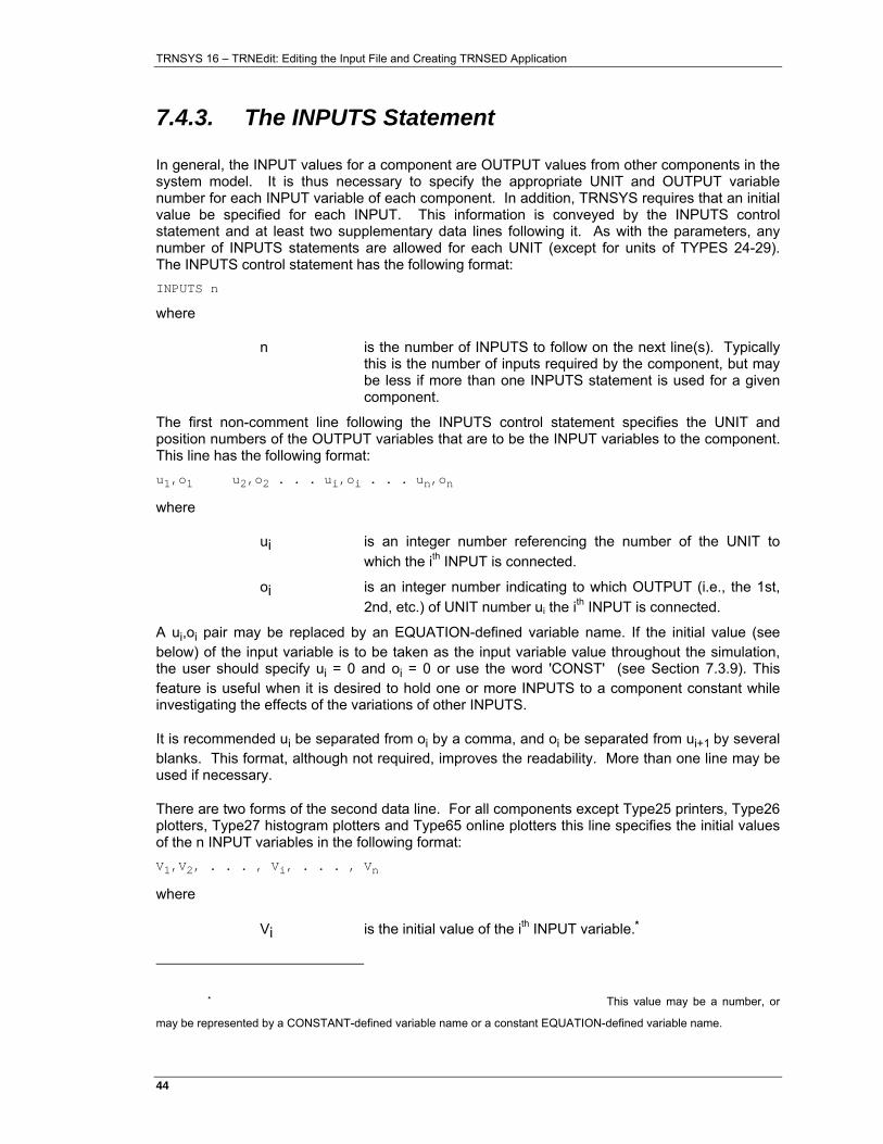
TRNSYS 16 – TRNEdit: Editing the Input File and Creating TRNSED Application
44�
7.4.3. The INPUTS Statement
In general, the INPUT values for a component are OUTPUT values from other components in the system model. It is thus necessary to specify the appropriate UNIT and OUTPUT variable number for each INPUT variable of each component. In addition, TRNSYS requires that an initial value be specified for each INPUT. This information is conveyed by the INPUTS control statement and at least two supplementary data lines following it. As with the parameters, any number of INPUTS statements are allowed for each UNIT (except for units of TYPES 24-29). The INPUTS control statement has the following format: INPUTS n
where
n is the number of INPUTS to follow on the next line(s). Typically this is the number of inputs required by the component, but may be less if more than one INPUTS statement is used for a given component.
The first non-comment line following the INPUTS control statement specifies the UNIT and position numbers of the OUTPUT variables that are to be the INPUT variables to the component. This line has the following format: u1,o1 u2,o2 . . . ui,oi . . . un,on
where
ui is an integer number referencing the number of the UNIT to which the ith INPUT is connected.
oi is an integer number indicating to which OUTPUT (i.e., the 1st, 2nd, etc.) of UNIT number ui the ith INPUT is connected.
A ui,oi pair may be replaced by an EQUATION-defined variable name. If the initial value (see below) of the input variable is to be taken as the input variable value throughout the simulation, the user should specify ui = 0 and oi = 0 or use the word 'CONST' (see Section 7.3.9). This feature is useful when it is desired to hold one or more INPUTS to a component constant while investigating the effects of the variations of other INPUTS.
It is recommended ui be separated from oi by a comma, and oi be separated from ui+1 by several blanks. This format, although not required, improves the readability. More than one line may be used if necessary.
There are two forms of the second data line. For all components except Type25 printers, Type26 plotters, Type27 histogram plotters and Type65 online plotters this line specifies the initial values of the n INPUT variables in the following format: V1,V2, . . . , Vi, . . . , Vn
where
Vi is the initial value of the ith INPUT variable.*
* This value may be a number, or
may be represented by a CONSTANT-defined variable name or a constant EQUATION-defined variable name.
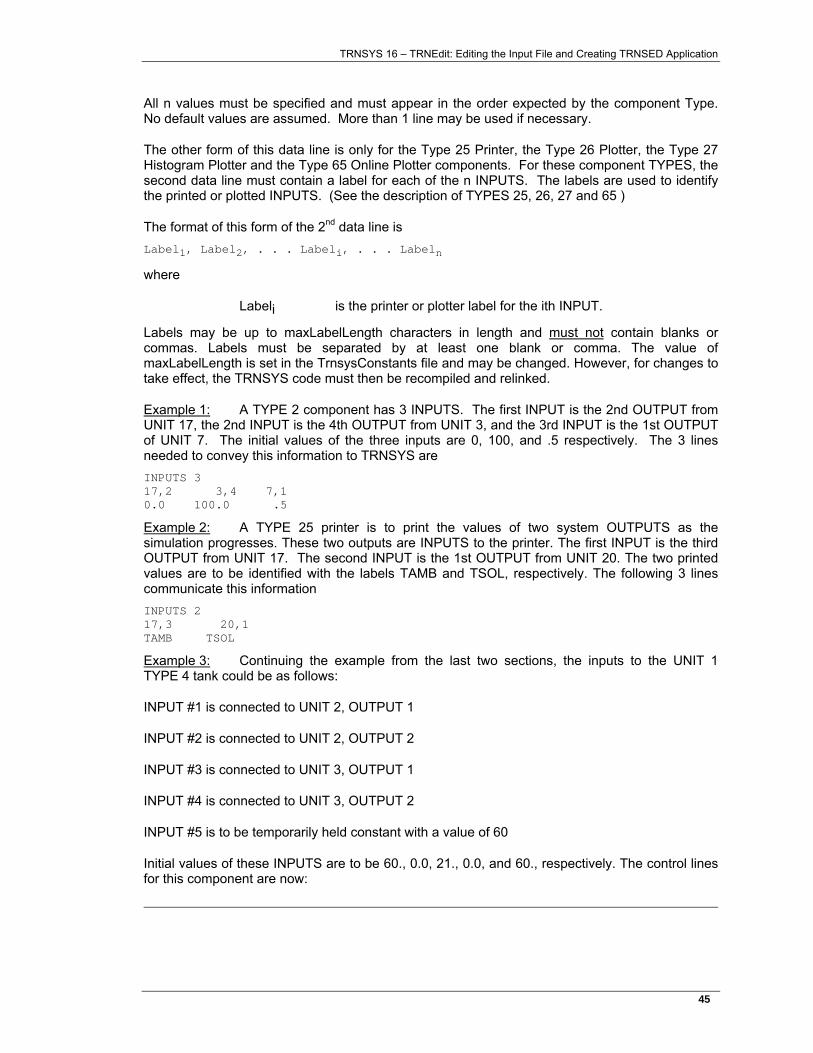
TRNSYS 16 – TRNEdit: Editing the Input File and Creating TRNSED Application
45�
All n values must be specified and must appear in the order expected by the component Type. No default values are assumed. More than 1 line may be used if necessary.
The other form of this data line is only for the Type 25 Printer, the Type 26 Plotter, the Type 27 Histogram Plotter and the Type 65 Online Plotter components. For these component TYPES, the second data line must contain a label for each of the n INPUTS. The labels are used to identify the printed or plotted INPUTS. (See the description of TYPES 25, 26, 27 and 65 )
The format of this form of the 2nd data line is Label1, Label2, . . . Labeli, . . . Labeln
where
Labeli is the printer or plotter label for the ith INPUT.
Labels may be up to maxLabelLength characters in length and must not contain blanks or commas. Labels must be separated by at least one blank or comma. The value of maxLabelLength is set in the TrnsysConstants file and may be changed. However, for changes to take effect, the TRNSYS code must then be recompiled and relinked.
Example 1: A TYPE 2 component has 3 INPUTS. The first INPUT is the 2nd OUTPUT from UNIT 17, the 2nd INPUT is the 4th OUTPUT from UNIT 3, and the 3rd INPUT is the 1st OUTPUT of UNIT 7. The initial values of the three inputs are 0, 100, and .5 respectively. The 3 lines needed to convey this information to TRNSYS are INPUTS 3 17,2 3,4 7,1 0.0 100.0 .5
Example 2: A TYPE 25 printer is to print the values of two system OUTPUTS as the simulation progresses. These two outputs are INPUTS to the printer. The first INPUT is the third OUTPUT from UNIT 17. The second INPUT is the 1st OUTPUT from UNIT 20. The two printed values are to be identified with the labels TAMB and TSOL, respectively. The following 3 lines communicate this information INPUTS 2 17,3 20,1 TAMB TSOL
Example 3: Continuing the example from the last two sections, the inputs to the UNIT 1 TYPE 4 tank could be as follows:
INPUT #1 is connected to UNIT 2, OUTPUT 1
INPUT #2 is connected to UNIT 2, OUTPUT 2
INPUT #3 is connected to UNIT 3, OUTPUT 1
INPUT #4 is connected to UNIT 3, OUTPUT 2
INPUT #5 is to be temporarily held constant with a value of 60
Initial values of these INPUTS are to be 60., 0.0, 21., 0.0, and 60., respectively. The control lines for this component are now:
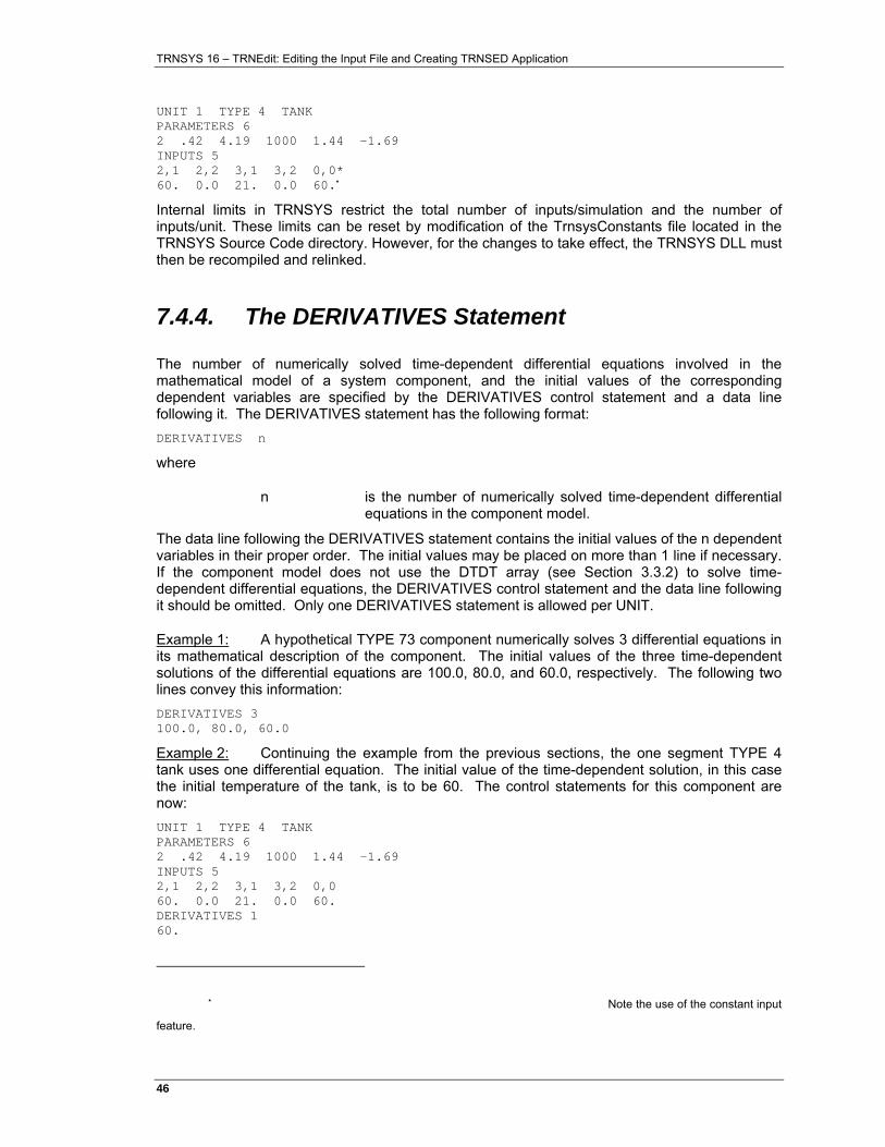
TRNSYS 16 – TRNEdit: Editing the Input File and Creating TRNSED Application
46�
UNIT 1 TYPE 4 TANK PARAMETERS 6 2 .42 4.19 1000 1.44 -1.69 INPUTS 5 2,1 2,2 3,1 3,2 0,0* 60. 0.0 21. 0.0 60.*
Internal limits in TRNSYS restrict the total number of inputs/simulation and the number of inputs/unit. These limits can be reset by modification of the TrnsysConstants file located in the TRNSYS Source Code directory. However, for the changes to take effect, the TRNSYS DLL must then be recompiled and relinked.
7.4.4. The DERIVATIVES Statement
The number of numerically solved time-dependent differential equations involved in the mathematical model of a system component, and the initial values of the corresponding dependent variables are specified by the DERIVATIVES control statement and a data line following it. The DERIVATIVES statement has the following format: DERIVATIVES n
where
n is the number of numerically solved time-dependent differential equations in the component model.
The data line following the DERIVATIVES statement contains the initial values of the n dependent variables in their proper order. The initial values may be placed on more than 1 line if necessary. If the component model does not use the DTDT array (see Section 3.3.2) to solve time-dependent differential equations, the DERIVATIVES control statement and the data line following it should be omitted. Only one DERIVATIVES statement is allowed per UNIT.
Example 1: A hypothetical TYPE 73 component numerically solves 3 differential equations in its mathematical description of the component. The initial values of the three time-dependent solutions of the differential equations are 100.0, 80.0, and 60.0, respectively. The following two lines convey this information: DERIVATIVES 3 100.0, 80.0, 60.0
Example 2: Continuing the example from the previous sections, the one segment TYPE 4 tank uses one differential equation. The initial value of the time-dependent solution, in this case the initial temperature of the tank, is to be 60. The control statements for this component are now: UNIT 1 TYPE 4 TANK PARAMETERS 6 2 .42 4.19 1000 1.44 -1.69 INPUTS 5 2,1 2,2 3,1 3,2 0,0 60. 0.0 21. 0.0 60. DERIVATIVES 1 60.
* Note the use of the constant input
feature.
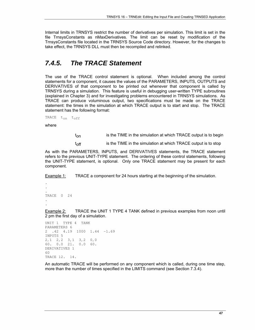
TRNSYS 16 – TRNEdit: Editing the Input File and Creating TRNSED Application
47�
Internal limits in TRNSYS restrict the number of derivatives per simulation. This limit is set in the file TrnsysConstants as nMaxDerivatives. The limit can be reset by modification of the TrnsysConstants file located in the TRNSYS Source Code directory. However, for the changes to take effect, the TRNSYS DLL must then be recompiled and relinked.
7.4.5. The TRACE Statement
The use of the TRACE control statement is optional. When included among the control statements for a component, it causes the values of the PARAMETERS, INPUTS, OUTPUTS and DERIVATIVES of that component to be printed out whenever that component is called by TRNSYS during a simulation. This feature is useful in debugging user-written TYPE subroutines (explained in Chapter 3) and for investigating problems encountered in TRNSYS simulations. As TRACE can produce voluminous output, two specifications must be made on the TRACE statement: the times in the simulation at which TRACE output is to start and stop. The TRACE statement has the following format: TRACE ton toff
where
ton is the TIME in the simulation at which TRACE output is to begin
toff is the TIME in the simulation at which TRACE output is to stop
As with the PARAMETERS, INPUTS, and DERIVATIVES statements, the TRACE statement refers to the previous UNIT-TYPE statement. The ordering of these control statements, following the UNIT-TYPE statement, is optional. Only one TRACE statement may be present for each component.
Example 1: TRACE a component for 24 hours starting at the beginning of the simulation. . . . TRACE 0 24 . .
Example 2: TRACE the UNIT 1 TYPE 4 TANK defined in previous examples from noon until 2 pm the first day of a simulation. UNIT 1 TYPE 4 TANK PARAMETERS 6 2 .42 4.19 1000 1.44 -1.69 INPUTS 5 2,1 2,2 3,1 3,2 0,0 60. 0.0 21. 0.0 60. DERIVATIVES 1 60 TRACE 12. 14.
An automatic TRACE will be performed on any component which is called, during one time step, more than the number of times specified in the LIMITS command (see Section 7.3.4).
TRNSYS 16 – TRNEdit: Editing the Input File and Creating TRNSED Application
48�
7.4.6. The ETRACE Statement
With TRNSYS version 15 and before, the tracing feature (through the TRACE command) was only available for debugging components. With the release of version 16, the ETRACE command was added, allowing users to not only trace the results of components, but also to trace the results of EQUATIONS on an every iteration basis. The format of the ETRACE Statement is: ETRACE TimeOn TimeOff
Where
TimeOn is the hour of the year at which EQUATION tracing should begin.
TimeOff is the hour of the year at which EQUATION tracing should end.
Turning on EQUATION tracing will not only print out the result of EQUATIONS at each time step but will also provide the user with information as to why the equation was called (TIME changed, the INPUTS to the equation changed, etc.)
7.4.7. The FORMAT Statement
An optional FORMAT statement can be used with the TYPE 25 printer and the TYPE 28 Simulation Summarizer to control the format of output which is directed to a file.
The format statement format is simply FORMAT
(valid FORTRAN Format Specification)
The FORTRAN format specification must have an open parenthesis in column 1 and must be no longer than maxFileWidth characters where maxFileWidth is a variable set in the TrnsysConstants file. Modification of the maxFileWidth variable requires recompilation of the TNRSYS DLL (TRNDll.dll). TRNSYS prints only real numbers so the format specifications for numbers must be either F or E formats.
The FORMAT statement only affects output for certain Types such as Type25 and Type28. More specifically, it affects Type 25 for which Lunit>0 (set by a PARAMETER) and Type28 in Output Mode =1; otherwise it is ignored. With the release of TRNSYS 16, and component can have a FORMAT associated with it.

TRNSYS 16 – TRNEdit: Editing the Input File and Creating TRNSED Application
49�
TRNSYS 16 – TRNEdit: Editing the Input File and Creating TRNSED Application
50�
7.5. Listing Control Statements
Listing control statements are used to specify the format of the TRNSYS output listing. They are: WIDTH, NOLIST, LIST, and MAP.
These control statements are all optional and default values are assumed if they are not present in the TRNSYS input file. The format and use of each of these control statements is defined in the next four sections. Only one WIDTH and one MAP card are allowed in a TRNSYS input file.
7.5.1. The WIDTH Statement
Note: This statement is obsolete
The WIDTH statement is an optional control statement is used to set the number of characters to be allowed on a line of TRNSYS output. The format of the WIDTH statement is as follows: WIDTH n
where
n is the number of characters per printed line; n must be between 72 and 132.
The WIDTH specification affects both the output of the TRNSYS processor and the output of the output-producing TRNSYS components. Suggested values of n are as follows: video screen 72 line printer 120 (or 132 if available)
If a WIDTH statement is not included in a TRNSYS input file, the number of printed characters per line is assumed to be 120 (mainframe) or 72 (personal computer).
Example: If a 132 character/line line printer is available, then a WIDTH statement of the following form may be included in the TRNSYS input file. WIDTH 132
7.5.2. The NOLIST Statement
The NOLIST statement is used to turn off the listing of the TRNSYS input file. It has the simple form: NOLIST
The NOLIST control statement affects only the output of the TRNSYS processor. It is useful in reducing TRNSYS output, which can make a simulation run significantly more quickly. The NOLIST statement does not override the printing of ERROR messages. As many NOLIST statements as desired may be placed in a TRNSYS input file. The NOLIST statement may be placed before the SIMULATION statement. It is best not to use the NOLIST statement until the input file has been thoroughly debugged since run time WARNINGS and ERRORS are printed to the list file.
TRNSYS 16 – TRNEdit: Editing the Input File and Creating TRNSED Application
51�
7.5.3. The LIST Statement
The LIST statement is used to turn on the TRNSYS processor listing after it has been turned off by a NOLIST statement. It has the form: LIST
The listing is assumed to be on at the beginning of a TRNSYS input file. As many LIST cards as desired may appear in a TRNSYS input file and may be located anywhere in the input file.
Example: The TRNSYS processor listing is to be turned off at the beginning of the input file, turned on for one set of component control cards and then turned back off for the rest of the input file. The following sequence of control cards is then used: SIMULATION 0 24 .25 NOLIST . . . LIST UNIT 1 TYPE 4 . . . NOLIST . END
7.5.4. The MAP Statement
The MAP statement is an optional control statement that is used to obtain a component output map listing which is particularly useful in debugging component interconnections. The MAP statement has the form: MAP
Recognition of the MAP control statement causes TRNSYS to print each component by its UNIT and TYPE numbers, followed by a list of its connected outputs and the UNIT, TYPE, and INPUT number to which each is connected. This printout occurs only after the EXEC subroutine (part of the TRNSYS kernel routines) has been called and therefore will not appear if the simulation is terminated by errors recognized by the input file processor. A sample map appears as follows:
TRNSYS COMPONENT OUTPUT MAP
UNIT 1 TYPE 9 UNIT/ TYPE/ INPUT
OUTPUT 4 3 1 5
OUTPUT 5 10 16 1
OUTPUT 6 3 1 3
4 12 3
UNIT 10 TYPE 16 UNIT/ TYPE/ INPUT
OUTPUT 1 3 1 4
etc.
TRNSYS 16 – TRNEdit: Editing the Input File and Creating TRNSED Application
52�
7.6. Comment Lines
Comment lines may be included at any location in the TRNSYS input file or data file. A comment line has either of the following two formats: * Comment ! Comment
In the first case (an asterisk) the '*' must appear in column one of the line and any line with a '*' in column one will be interpreted as a comment line. The entire line is printed without modification.
Example: *THIS IS AN EXAMPLE OF A COMMENT LINE *THIS IS ANOTHER ONE *ETC
In the second case, any text appearing after the exclamation point is ignored by the TRNSYS processor. Any text appearing before the exclamation point is processed by the kernel however.
Example: EQUATIONS 1 AA = [5,6]*Efficiency !AA is output six of unit 5 multiplied by the efficiency.

TRNSYS 16 – TRNEdit: Editing the Input File and Creating TRNSED Application
53�
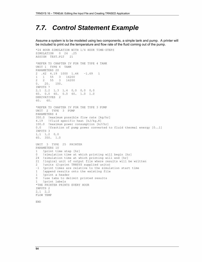
TRNSYS 16 – TRNEdit: Editing the Input File and Creating TRNSED Application
54�
7.7. Control Statement Example
Assume a system is to be modeled using two components, a simple tank and pump. A printer will be included to print out the temperature and flow rate of the fluid coming out of the pump. *24 HOUR SIMULATION WITH 1/4 HOUR TIME-STEPS SIMULATION 0 24 .25 ASSIGN TEST.PLT 21 *REFER TO CHAPTER IV FOR THE TYPE 4 TANK UNIT 1 TYPE 4 TANK PARAMETERS 20 2 .42 4.19 1000 1.44 -1.69 1 1 1 55 3 16200 2 2 55 3 16200 0. 20. 100. INPUTS 7 2,1 2,2 1,3 1,4 0,0 0,0 0,0 60. 0.0 60. 0.0 60. 1.0 1.0 DERIVATIVES 2 60. 60. *REFER TO CHAPTER IV FOR THE TYPE 3 PUMP UNIT 2 TYPE 3 PUMP PARAMETERS 4 350.0 !maximum possible flow rate [kg/hr] 4.19 !fluid specific heat [kJ/kg.K] 100.0 !maximum power consumption [kJ/hr] 0.0 !fraction of pump power converted to fluid thermal energy [0..1] INPUTS 3 1,1 1,2 0,0 60. 350. 1.0 UNIT 3 TYPE 25 PRINTER PARAMETERS 10 1 !print time step [hr] 0 !simulation time at which printing will begin [hr] 24 !simulation time at which printing will end [hr] 21 !logical unit of output file where results will be written 2 !units (2:print TRNSYS supplied units) -1 !print times are relative to the simulation start time 1 !append results onto the existing file 1 !print a header 0 !use tabs to delimit printed results 1 !print labels *THE PRINTER PRINTS EVERY HOUR INPUTS 2 2,1 2,2 FLOW TEMP END

TRNSYS 16 – TRNEdit: Editing the Input File and Creating TRNSED Application
55�
TRNSYS 16 – TRNEdit: Editing the Input File and Creating TRNSED Application
56�
7.8. Data Echo and Control Statement Errors
The information contained for each statement of the TRNSYS input file described in the preceding sections is processed by TRNSYS. Provided there are no errors on the line and that the listing has not been turned off by a NOLIST statement, it is reproduced in a neat format on the output before the simulation begins. With a few exceptions, any errors detected in the input file will terminate the attempted simulation after all the lines in the input file have been processed. TRNSYS is programmed to respond to most input errors with appropriate error messages, however, the error checking facility of TRNSYS is not foolproof.

TRNSYS 16 – TRNEdit: Editing the Input File and Creating TRNSED Application
57�
TRNSYS 16 – TRNEdit: Editing the Input File and Creating TRNSED Application
58�
7.9. Summary of Input File Syntax
A TRNSYS simulation is defined and controlled by a set of control statements and data lines as described in this chapter. A SIMULATION statement must appear in each TRNSYS input file, usually near the beginning of the input file. TOLERANCES, LIMITS, CONSTANTS, EQUATIONS, ACCELERATE, LOOP-REPEAT, DFQ, NOCHECK, EQSOLVER, SOLVER and ASSIGN statements are optional. These control statements are discussed in Section 7.3.
Each component in the system model is identified by a UNIT-TYPE statement, followed by statements that assign values to component parameters, identify sources for all component inputs, and assign initial values to inputs and to time-dependent differential equations (if any). An optional TRACE statement (or ETRACE in the case of EQUATIONS blocks) is available to aid in debugging user-written TYPE subroutines (see Manual 08-Programmer’s Guide) and for investigating problems encountered in TRNSYS simulations. An optional FORMAT statement can be used to specify the format of output from certain components. These component control statements are discussed in Section 7.4
Several optional statements are available which influence the TRNSYS output listing. These are discussed in Section 0. The MAP control statement is particularly useful in debugging component interconnections.
Comment lines and blank lines may also be included in the TRNSYS input file. The control input file must end with an END statement.
The TRNSYS processor requires only the first three characters of each control statement. Thus SIM can be used for SIMULATION, TOL for TOLERANCES, etc.

TRNSYS 16 – TRNEdit: Editing the Input File and Creating TRNSED Application
59�

TRNSYS 16 – TRNEdit: Editing the Input File and Creating TRNSED Application
60�
7.10. How to create TRNSED applications
This section explains how to create a TRNSYS-based redistributable application using the Simulation Studio and TRNEdit / TRNSED.
Please check the note on special licensing aspects of TRNSED applications in the introduction to this document
7.10.1. Starting point: TRNSYS Studio project
Open Examples\TRNSED-Advanced\SDHW-TRNSED (Studio).tpf. This is a slightly modified version of the SDHW example. The modifications are listed here below:
Set "Write TRNSED Commands" to "true" and change the deck file name in Control Cards. The deck filename should say: SDHW-TRNSED (Studio).trd. TRNSED applications must have a .trd extension.
Figure 7–14: Modified Control Cards for TRNSED projects
TRNSED will present a simplified view of the projects, with only some of the parameters available to users. You need to select those parameters by keeping them "unlocked", while you "lock" all other parameters to hide them.
This is done by opening the proformas of all components in the simulation and clicking on the lock icon for the corresponding parameters. It is also possible to lock all parameters of one components by clicking on the lock icon in the upper left corner of each tab. You must lock all fields in the Studio that you don't want users to be able to change. This includes parameters but also initial values for inputs and derivatives, and filenames (see Figure 7–15 for an example).
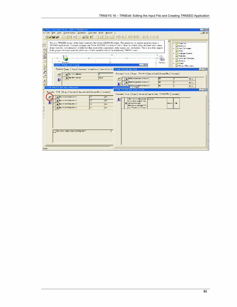
TRNSYS 16 – TRNEdit: Editing the Input File and Creating TRNSED Application
61�
Figure 7–15: Locking parameters, initial input values, file names, derivatives initial values
In this case, we will let users change the weather data file used, the solar collector slope and azimuth (Set in Type 109, the weather data processor), the solar collector area, the tank volume and the setpoints for auxiliary heating and for domestic hot water after the mixing valve. All other input fields should be locked.
Once all the "lock-unlock" settings are correct, you can generate the TRNSYS input file (the TRNSED deck in this case) by using "Calculate / Create input file" or using the "pen" button.
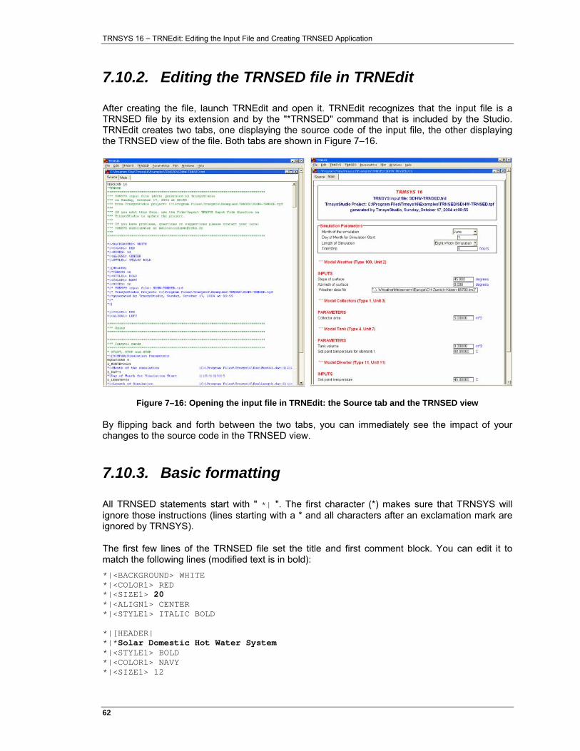
TRNSYS 16 – TRNEdit: Editing the Input File and Creating TRNSED Application
62�
7.10.2. Editing the TRNSED file in TRNEdit
After creating the file, launch TRNEdit and open it. TRNEdit recognizes that the input file is a TRNSED file by its extension and by the "*TRNSED" command that is included by the Studio. TRNEdit creates two tabs, one displaying the source code of the input file, the other displaying the TRNSED view of the file. Both tabs are shown in Figure 7–16.
Figure 7–16: Opening the input file in TRNEdit: the Source tab and the TRNSED view
By flipping back and forth between the two tabs, you can immediately see the impact of your changes to the source code in the TRNSED view.
7.10.3. Basic formatting
All TRNSED statements start with " *| ". The first character (*) makes sure that TRNSYS will ignore those instructions (lines starting with a * and all characters after an exclamation mark are ignored by TRNSYS).
The first few lines of the TRNSED file set the title and first comment block. You can edit it to match the following lines (modified text is in bold): *|<BACKGROUND> WHITE *|<COLOR1> RED *|<SIZE1> 20 *|<ALIGN1> CENTER *|<STYLE1> ITALIC BOLD *|[HEADER| *|*Solar Domestic Hot Water System *|<STYLE1> BOLD *|<COLOR1> NAVY *|<SIZE1> 12
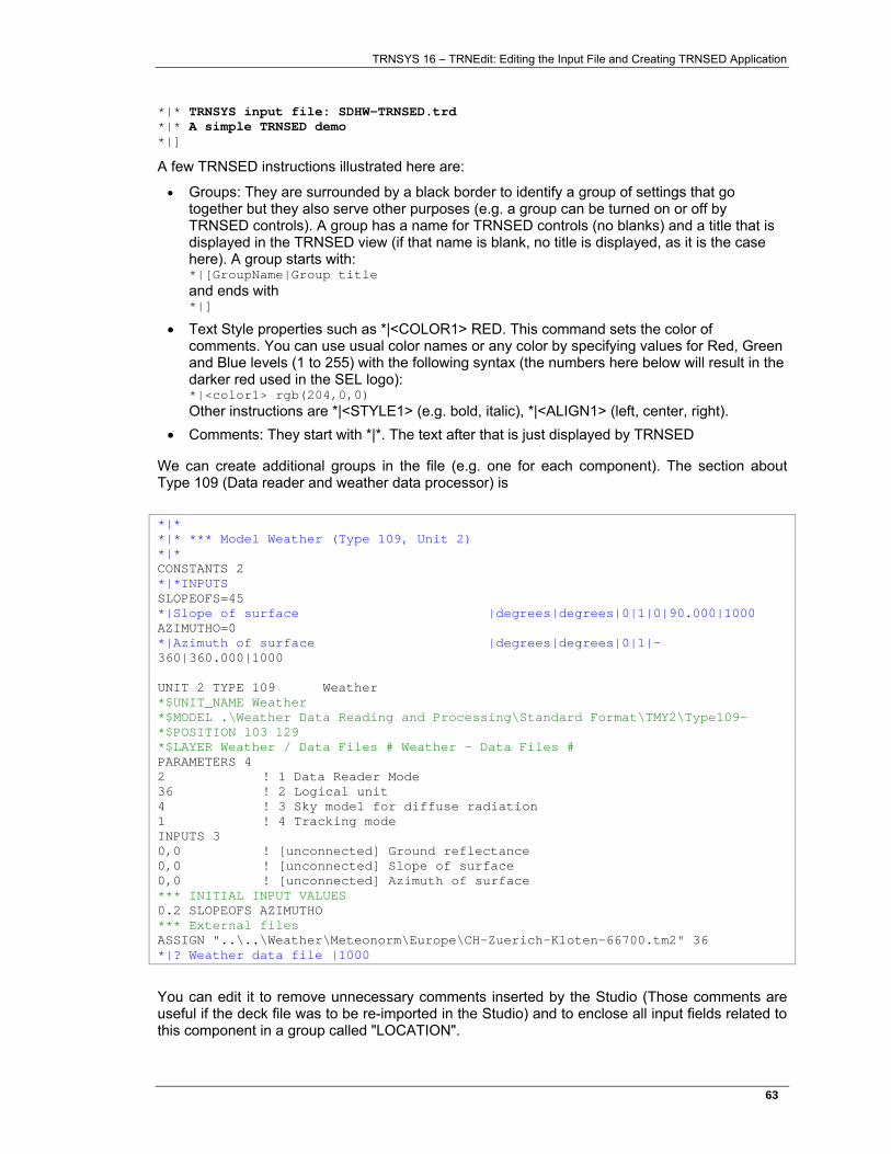
TRNSYS 16 – TRNEdit: Editing the Input File and Creating TRNSED Application
63�
*|* TRNSYS input file: SDHW-TRNSED.trd *|* A simple TRNSED demo *|]
A few TRNSED instructions illustrated here are:
• Groups: They are surrounded by a black border to identify a group of settings that go together but they also serve other purposes (e.g. a group can be turned on or off by TRNSED controls). A group has a name for TRNSED controls (no blanks) and a title that is displayed in the TRNSED view (if that name is blank, no title is displayed, as it is the case here). A group starts with: *|[GroupName|Group title and ends with *|]
• Text Style properties such as *|<COLOR1> RED. This command sets the color of comments. You can use usual color names or any color by specifying values for Red, Green and Blue levels (1 to 255) with the following syntax (the numbers here below will result in the darker red used in the SEL logo): *|<color1> rgb(204,0,0) Other instructions are *|<STYLE1> (e.g. bold, italic), *|<ALIGN1> (left, center, right).
• Comments: They start with *|*. The text after that is just displayed by TRNSED
We can create additional groups in the file (e.g. one for each component). The section about Type 109 (Data reader and weather data processor) is *|* *|* *** Model Weather (Type 109, Unit 2) *|* CONSTANTS 2 *|*INPUTS SLOPEOFS=45 *|Slope of surface |degrees|degrees|0|1|0|90.000|1000 AZIMUTHO=0 *|Azimuth of surface |degrees|degrees|0|1|-360|360.000|1000 UNIT 2 TYPE 109 Weather *$UNIT_NAME Weather *$MODEL .\Weather Data Reading and Processing\Standard Format\TMY2\Type109- *$POSITION 103 129 *$LAYER Weather / Data Files # Weather - Data Files # PARAMETERS 4 2 ! 1 Data Reader Mode 36 ! 2 Logical unit 4 ! 3 Sky model for diffuse radiation 1 ! 4 Tracking mode INPUTS 3 0,0 ! [unconnected] Ground reflectance 0,0 ! [unconnected] Slope of surface 0,0 ! [unconnected] Azimuth of surface *** INITIAL INPUT VALUES 0.2 SLOPEOFS AZIMUTHO *** External files ASSIGN "..\..\Weather\Meteonorm\Europe\CH-Zuerich-Kloten-66700.tm2" 36 *|? Weather data file |1000
You can edit it to remove unnecessary comments inserted by the Studio (Those comments are useful if the deck file was to be re-imported in the Studio) and to enclose all input fields related to this component in a group called "LOCATION".
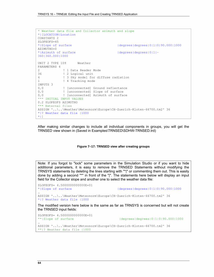
TRNSYS 16 – TRNEdit: Editing the Input File and Creating TRNSED Application
64�
* Weather data file and Collector azimuth and slope *|[LOCATION|Location CONSTANTS 2 SLOPEOFS=45 *|Slope of surface |degrees|degrees|0|1|0|90.000|1000 AZIMUTHO=0 *|Azimuth of surface |degrees|degrees|0|1|-360|360.000|1000 UNIT 2 TYPE 109 Weather PARAMETERS 4 2 ! 1 Data Reader Mode 36 ! 2 Logical unit 4 ! 3 Sky model for diffuse radiation 1 ! 4 Tracking mode INPUTS 3 0,0 ! [unconnected] Ground reflectance 0,0 ! [unconnected] Slope of surface 0,0 ! [unconnected] Azimuth of surface *** INITIAL INPUT VALUES 0.2 SLOPEOFS AZIMUTHO *** External files ASSIGN "..\..\Weather\Meteonorm\Europe\CH-Zuerich-Kloten-66700.tm2" 36 *|? Weather data file |1000 *|]
After making similar changes to include all individual components in groups, you will get the TRNSED view shown in (Saved in Examples\TRNSED\SDHW-TRNSED.trd)
Figure 7–17: TRNSED view after creating groups
Note: If you forgot to "lock" some parameters in the Simulation Studio or if you want to hide additional parameters, it is easy to remove the TRNSED Statements without modifying the TRNSYS statements by deleting the lines starting with "*|" or commenting them out. This is easily done by adding a second "*" in front of the "|". The statements here below will display an input field for the Collector slope and another one to select the weather data file: SLOPEOFS= 4.5000000000000E+01 *|Slope of surface |degrees|degrees|0|1|0|90.000|1000 … ASSIGN "..\..\Weather\Meteonorm\Europe\CH-Zuerich-Kloten-66700.tm2" 36 *|? Weather data file |1000
The modified version here below is the same as far as TRNSYS is concerned but will not create the TRNSED input fields: SLOPEOFS= 4.5000000000000E+01 **|Slope of surface |degrees|degrees|0|1|0|90.000|1000 … ASSIGN "..\..\Weather\Meteonorm\Europe\CH-Zuerich-Kloten-66700.tm2" 36 **|? Weather data file |1000
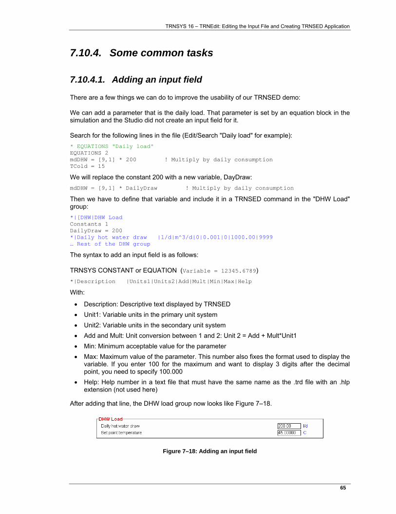
TRNSYS 16 – TRNEdit: Editing the Input File and Creating TRNSED Application
65�
7.10.4. Some common tasks
7.10.4.1. Adding an input field
There are a few things we can do to improve the usability of our TRNSED demo:
We can add a parameter that is the daily load. That parameter is set by an equation block in the simulation and the Studio did not create an input field for it.
Search for the following lines in the file (Edit/Search "Daily load" for example): * EQUATIONS "Daily load" EQUATIONS 2 mdDHW = [9,1] * 200 ! Multiply by daily consumption TCold = 15
We will replace the constant 200 with a new variable, DayDraw: mdDHW = [9,1] * DailyDraw ! Multiply by daily consumption
Then we have to define that variable and include it in a TRNSED command in the "DHW Load" group: *|[DHW|DHW Load Constants 1 DailyDraw = 200 *|Daily hot water draw |l/d|m^3/d|0|0.001|0|1000.00|9999 … Rest of the DHW group
The syntax to add an input field is as follows:
TRNSYS CONSTANT or EQUATION (Variable = 12345.6789) *|Description |Units1|Units2|Add|Mult|Min|Max|Help
With:
• Description: Descriptive text displayed by TRNSED • Unit1: Variable units in the primary unit system • Unit2: Variable units in the secondary unit system • Add and Mult: Unit conversion between 1 and 2: Unit 2 = Add + Mult*Unit1 • Min: Minimum acceptable value for the parameter • Max: Maximum value of the parameter. This number also fixes the format used to display the
variable. If you enter 100 for the maximum and want to display 3 digits after the decimal point, you need to specify 100.000
• Help: Help number in a text file that must have the same name as the .trd file with an .hlp extension (not used here)
After adding that line, the DHW load group now looks like Figure 7–18.
Figure 7–18: Adding an input field
TRNSYS 16 – TRNEdit: Editing the Input File and Creating TRNSED Application
66�
7.10.4.2. Reorganizing TRNSED fields
We could consider removing the "Location" Group. The weather data file choice would move to the "Simulation Parameters" group and the collector slope and azimuth would move to the "Solar collector" group.
Note: When moving TRNSED commands around, it is important to remember that the file has to be run by TRNSYS. It is important to comply with the TRNSYS syntax when modifying a TRNSED input file
The initial view is shown in Figure 7–19
Figure 7–19: Reorganizing the input file (1)
To modify the file:
Move the opening command for the "solar collector" group up and replace the existing opening of the "Location" group with it. Delete the closing statement (*|]) for group "Location". The result is shown in Figure 7–20.
Figure 7–20: Reorganizing the input file (2)
Move the commands that allow users to select the input file up, into the "Simulation Parameters" group. The two lines making the statement are: ASSIGN "..\..\Weather\Meteonorm\Europe\CH-Zuerich-Kloten-66700.tm2" 36 *|? Weather data file |1000
You must move both lines together. Note that TRNSYS will associate the file correctly with the data reader thanks to the logical number unit (36) which is among the parameters of Type 109. Move both lines just above the closing statement for the "SIMPAR" group. It may also be a good
TRNSYS 16 – TRNEdit: Editing the Input File and Creating TRNSED Application
67�
idea to prevent users from changing the simulation time step by adding a "*" in front of the line that defines the input field: "*|Timestep …" becomes "**|Timestep …". The result is shown in .
Figure 7–21: Reorganizing the input file (2)
7.10.5. Adding pictures and links
7.10.5.1. Pictures
We will first add system schematics to the file to make it more user-friendly. TRNSED can use *.bmp and *.jpeg files. The "Examples\TRNSED-Advanced\Images" folder contains "SDHW-Schematics.bmp", which we will use as the main picture. That picture was created from a screen shot of the TRNSYS Studio after hiding the output layer to simplify the schematic.
We will include that picture in the first group. Just add the following line of code before the closing command for the group, after the "*|*A Simple TRNSED Demo" line: *|<img src="Images\SDHW-Schematics.bmp">
The syntax used to add pictures is very close to the HTML syntax (with the additional "*|" code at the beginning of the line). Figure 7–22 shows a screenshot of the main application tab (the only tab so far) after inserting a picture.
TRNSYS 16 – TRNEdit: Editing the Input File and Creating TRNSED Application
68�
Figure 7–22: Screenshot of SDHW-TRNSED-Advanced.trd, main screen
7.10.5.2. Links
You will notice that the picture includes a "question mark icon" that invites user to click for help. TRNSED allows you to associate actions with pictures. In this simple example, we will launch a help file (HTML document) when the user clicks anywhere in the picture.
To associate a link to a file or program with a picture, just add a "href=…" instruction to the "img" tag: *|<img src="Images\SDHW-Schematics.bmp" href="Help\SDHW-Help.html">
You can also display a hint for users when they move the mouse over the picture by adding a "hint" instruction: *|<img src="Images\SDHW-Schematics.bmp" href="Help\SDHW-Help.html" hint="Click for help">
TRNSYS 16 – TRNEdit: Editing the Input File and Creating TRNSED Application
69�
7.10.6. Multiple tabs
7.10.6.1. Adding multiple tabs
Now that we have a picture on the main page, it might be a good idea to distribute the components in different tabs so that the user does not have to scroll down too much to make changes to the configuration.
Tabs are similar to groups in that they require an opening and a closing tag, and they have a name: *|<TabWindow name="Solar Collector"> … All TRNSED commands that should appear in the "solar collector" tab … *|</TabWindow>
In this simple example, we can include each component (each group we created before) in a separate tab. For the "Simulation parameters group, we have: *|<TabWindow name="Simulation parameters"> *|[SIMPAR|Simulation Parameters EQUATIONS 5 I_MONTH=3624 … ASSIGN "..\..\Weather\Meteonorm\Europe\CH-Zuerich-Kloten-66700.tm2" 36 *|? Weather data file |1000 *|] *|</TabWindow>
Note: so far, each tab window has only one group. In general, you can include several groups in a tab. However, Each group can only be part of one tab: the same group cannot span across several tab windows.
7.10.6.2. Links between tabs
The user will be able to navigate between tabs by clicking on their name. Tabs can also be linked by pictures. We will add a "Back" link to the main tab from all other ones. In order to do this, we add a group to the "Simulation Parameters" Tab window: *|<TabWindow name="Simulation parameters"> *|[SIMPAR|Simulation Parameters … *|] *|[SIMPAR-Back| *|<img src="Images\Back.bmp" align="center" href="#Main" hint="back to main"> *|] *|</TabWindow>
And we can do the same for all tabs. The "Solar collector" tab now looks like Figure 7–23.
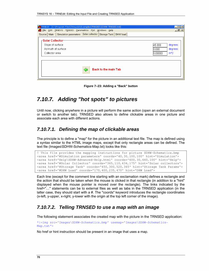
TRNSYS 16 – TRNEdit: Editing the Input File and Creating TRNSED Application
70�
Figure 7–23: Adding a "Back" button
7.10.7. Adding "hot spots" to pictures
Until now, clicking anywhere in a picture will perform the same action (open an external document or switch to another tab). TRNSED also allows to define clickable areas in one picture and associate each area with different actions.
7.10.7.1. Defining the map of clickable areas
The principle is to define a "map" for the picture in an additional text file. The map is defined using a syntax similar to the HTML image maps, except that only rectangle areas can be defined. The text file (Images\SDHW-Schematics-Map.txt) looks like this:
! This file provides the mapping instructions for picture SDHW-Schematics.bmp <area href="#Simulation parameters" coords="40,30,100,100" hint="Simulation"> <area href="Help\SDHW-Advanced-Help.html" coords="600,30,660,100" hint="Help"> <area href="#Solar Collector" coords="365,110,434,175" hint="Solar collectors"> <area href="#Storage Tank" coords="450,300,520,365" hint="Storage Tank Params"> <area href="#DHW Load" coords="170,400,235,470" hint="DHW Load">
Each line (except for the comment line starting with an exclamation mark) defines a rectangle and the action that should be taken when the mouse is clicked in that rectangle (in addition to a "hint" displayed when the mouse pointer is moved over the rectangle). The links indicated by the href="…" statements can be to external files as well as tabs in the TRNSED application (in the latter case, they should start with a #. The "coords" keyword introduces the rectangle coordinates (x-left, y-upper, x-right, y-lower with the origin at the top left corner of the image).
7.10.7.2. Telling TRNSED to use a map with an image
The following statement associates the created map with the picture in the TRNSED application: *|<img src="Images\SDHW-Schematics.bmp" usemap="Images\SDHW-Schematics-Map.txt">
No href or hint instruction should be present in an image that uses a map.
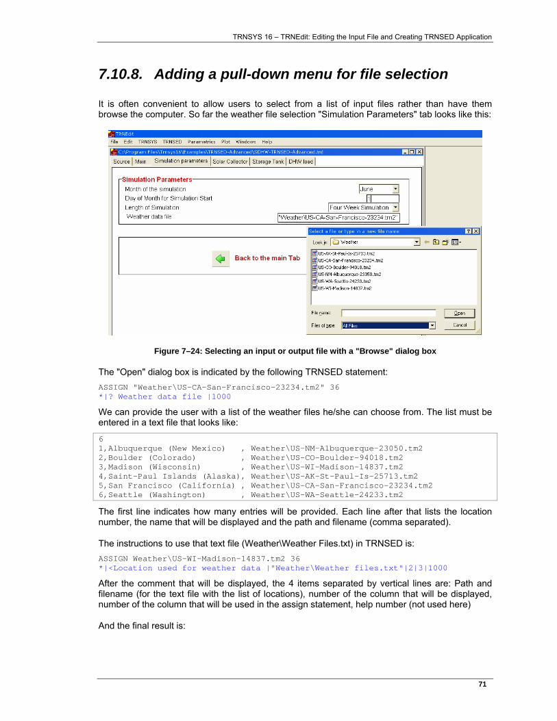
TRNSYS 16 – TRNEdit: Editing the Input File and Creating TRNSED Application
71�
7.10.8. Adding a pull-down menu for file selection
It is often convenient to allow users to select from a list of input files rather than have them browse the computer. So far the weather file selection "Simulation Parameters" tab looks like this:
Figure 7–24: Selecting an input or output file with a "Browse" dialog box
The "Open" dialog box is indicated by the following TRNSED statement: ASSIGN "Weather\US-CA-San-Francisco-23234.tm2" 36 *|? Weather data file |1000
We can provide the user with a list of the weather files he/she can choose from. The list must be entered in a text file that looks like:
6 1,Albuquerque (New Mexico) , Weather\US-NM-Albuquerque-23050.tm2 2,Boulder (Colorado) , Weather\US-CO-Boulder-94018.tm2 3,Madison (Wisconsin) , Weather\US-WI-Madison-14837.tm2 4,Saint-Paul Islands (Alaska), Weather\US-AK-St-Paul-Is-25713.tm2 5,San Francisco (California) , Weather\US-CA-San-Francisco-23234.tm2 6,Seattle (Washington) , Weather\US-WA-Seattle-24233.tm2
The first line indicates how many entries will be provided. Each line after that lists the location number, the name that will be displayed and the path and filename (comma separated).
The instructions to use that text file (Weather\Weather Files.txt) in TRNSED is: ASSIGN Weather\US-WI-Madison-14837.tm2 36 *|<Location used for weather data |"Weather\Weather files.txt"|2|3|1000
After the comment that will be displayed, the 4 items separated by vertical lines are: Path and filename (for the text file with the list of locations), number of the column that will be displayed, number of the column that will be used in the assign statement, help number (not used here)
And the final result is:
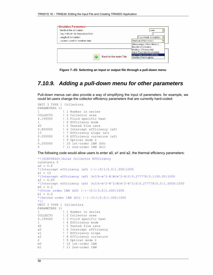
TRNSYS 16 – TRNEdit: Editing the Input File and Creating TRNSED Application
72�
Figure 7–25: Selecting an input or output file through a pull-down menu
7.10.9. Adding a pull-down menu for other parameters
Pull-down menus can also provide a way of simplifying the input of parameters: for example, we could let users change the collector efficiency parameters that are currently hard-coded: UNIT 3 TYPE 1 Collectors PARAMETERS 11 1 ! 1 Number in series COLLECTO ! 2 Collector area 4.190000 ! 3 Fluid specific heat 1 ! 4 Efficiency mode 40 ! 5 Tested flow rate 0.800000 ! 6 Intercept efficiency (a0) 13 ! 7 Efficiency slope (a1) 0.050000 ! 8 Efficiency curvature (a2) 2 ! 9 Optical mode 2 0.200000 ! 10 1st-order IAM (b0) 0 ! 11 2nd-order IAM (b1)
The following code would allow users to enter a0, a1 and a2, the thermal efficiency parameters: *|[ScEffEdit|Solar Collector Efficiency constants 5 a0 = 0.8 *|Intercept efficiency (a0) |-|-|0|1|0.0|1.000|1000 a1 = 13 *|Intercept efficiency (a0) |kJ/h-m^2-K|W/m^2-K|0|0.277778|0.1|50.00|1000 a2 = 0.05 *|Intercept efficiency (a0) |kJ/h-m^2-K^2|W/m^2-K^2|0|0.277778|0.0|1.0000|1000 b0 = 0.2 *|First order IAM (b0) |-|-|0|1|0.0|1.000|1000 b1 = 0.0 *|Second order IAM (b1) |-|-|0|1|0.0|1.000|1000 *|] UNIT 3 TYPE 1 Collectors PARAMETERS 11 1 ! 1 Number in series COLLECTO ! 2 Collector area 4.190000 ! 3 Fluid specific heat 1 ! 4 Efficiency mode 40 ! 5 Tested flow rate a0 ! 6 Intercept efficiency a1 ! 7 Efficiency slope a2 ! 8 Efficiency curvature 2 ! 9 Optical mode 2 b0 ! 10 1st-order IAM b1 ! 11 2nd-order IAM
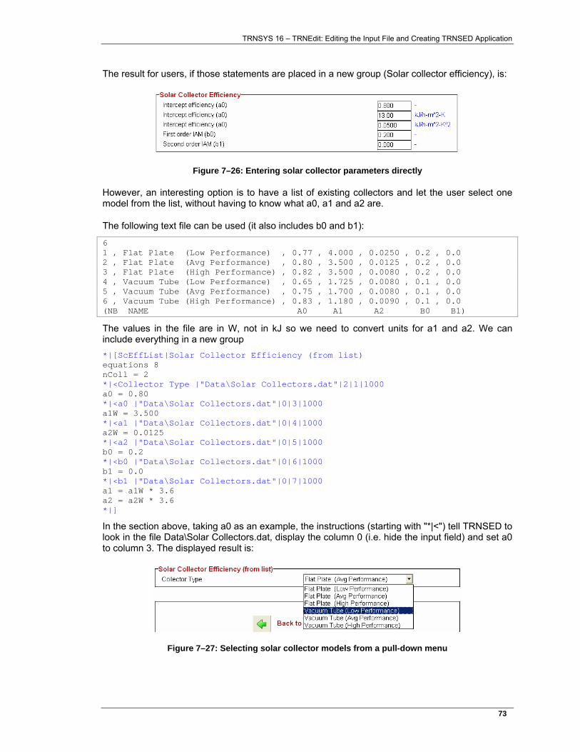
TRNSYS 16 – TRNEdit: Editing the Input File and Creating TRNSED Application
73�
The result for users, if those statements are placed in a new group (Solar collector efficiency), is:
Figure 7–26: Entering solar collector parameters directly
However, an interesting option is to have a list of existing collectors and let the user select one model from the list, without having to know what a0, a1 and a2 are.
The following text file can be used (it also includes b0 and b1):
6 1 , Flat Plate (Low Performance) , 0.77 , 4.000 , 0.0250 , 0.2 , 0.0 2 , Flat Plate (Avg Performance) , 0.80 , 3.500 , 0.0125 , 0.2 , 0.0 3 , Flat Plate (High Performance) , 0.82 , 3.500 , 0.0080 , 0.2 , 0.0 4 , Vacuum Tube (Low Performance) , 0.65 , 1.725 , 0.0080 , 0.1 , 0.0 5 , Vacuum Tube (Avg Performance) , 0.75 , 1.700 , 0.0080 , 0.1 , 0.0 6 , Vacuum Tube (High Performance) , 0.83 , 1.180 , 0.0090 , 0.1 , 0.0 (NB NAME A0 A1 A2 B0 B1)
The values in the file are in W, not in kJ so we need to convert units for a1 and a2. We can include everything in a new group *|[ScEffList|Solar Collector Efficiency (from list) equations 8 nColl = 2 *|<Collector Type |"Data\Solar Collectors.dat"|2|1|1000 a0 = 0.80 *|<a0 |"Data\Solar Collectors.dat"|0|3|1000 a1W = 3.500 *|<a1 |"Data\Solar Collectors.dat"|0|4|1000 a2W = 0.0125 *|<a2 |"Data\Solar Collectors.dat"|0|5|1000 b0 = 0.2 *|<b0 |"Data\Solar Collectors.dat"|0|6|1000 b1 = 0.0 *|<b1 |"Data\Solar Collectors.dat"|0|7|1000 a1 = a1W * 3.6 a2 = a2W * 3.6 *|]
In the section above, taking a0 as an example, the instructions (starting with "*|<") tell TRNSED to look in the file Data\Solar Collectors.dat, display the column 0 (i.e. hide the input field) and set a0 to column 3. The displayed result is:
Figure 7–27: Selecting solar collector models from a pull-down menu
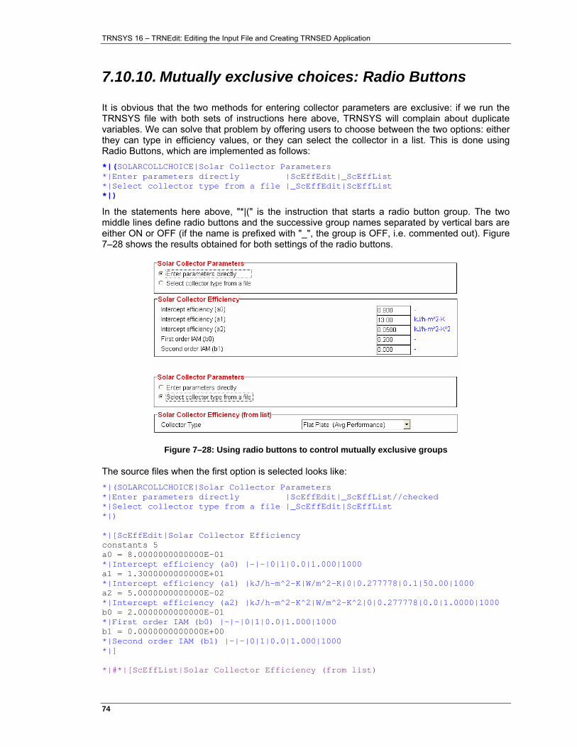
TRNSYS 16 – TRNEdit: Editing the Input File and Creating TRNSED Application
74�
7.10.10. Mutually exclusive choices: Radio Buttons
It is obvious that the two methods for entering collector parameters are exclusive: if we run the TRNSYS file with both sets of instructions here above, TRNSYS will complain about duplicate variables. We can solve that problem by offering users to choose between the two options: either they can type in efficiency values, or they can select the collector in a list. This is done using Radio Buttons, which are implemented as follows: *|(SOLARCOLLCHOICE|Solar Collector Parameters *|Enter parameters directly |ScEffEdit|_ScEffList *|Select collector type from a file |_ScEffEdit|ScEffList *|)
In the statements here above, "*|(" is the instruction that starts a radio button group. The two middle lines define radio buttons and the successive group names separated by vertical bars are either ON or OFF (if the name is prefixed with "_", the group is OFF, i.e. commented out). Figure 7–28 shows the results obtained for both settings of the radio buttons.
Figure 7–28: Using radio buttons to control mutually exclusive groups
The source files when the first option is selected looks like: *|(SOLARCOLLCHOICE|Solar Collector Parameters *|Enter parameters directly |ScEffEdit|_ScEffList//checked *|Select collector type from a file |_ScEffEdit|ScEffList *|) *|[ScEffEdit|Solar Collector Efficiency constants 5 a0 = 8.0000000000000E-01 *|Intercept efficiency (a0) |-|-|0|1|0.0|1.000|1000 a1 = 1.3000000000000E+01 *|Intercept efficiency (a1) |kJ/h-m^2-K|W/m^2-K|0|0.277778|0.1|50.00|1000 a2 = 5.0000000000000E-02 *|Intercept efficiency (a2) |kJ/h-m^2-K^2|W/m^2-K^2|0|0.277778|0.0|1.0000|1000 b0 = 2.0000000000000E-01 *|First order IAM (b0) |-|-|0|1|0.0|1.000|1000 b1 = 0.0000000000000E+00 *|Second order IAM (b1) |-|-|0|1|0.0|1.000|1000 *|] *|#*|[ScEffList|Solar Collector Efficiency (from list)
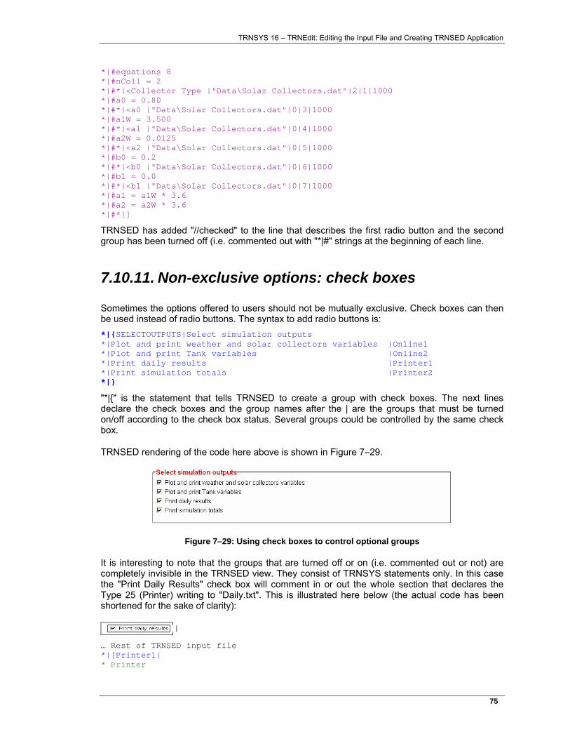
TRNSYS 16 – TRNEdit: Editing the Input File and Creating TRNSED Application
75�
*|#equations 8 *|#nColl = 2 *|#*|<Collector Type |"Data\Solar Collectors.dat"|2|1|1000 *|#a0 = 0.80 *|#*|<a0 |"Data\Solar Collectors.dat"|0|3|1000 *|#a1W = 3.500 *|#*|<a1 |"Data\Solar Collectors.dat"|0|4|1000 *|#a2W = 0.0125 *|#*|<a2 |"Data\Solar Collectors.dat"|0|5|1000 *|#b0 = 0.2 *|#*|<b0 |"Data\Solar Collectors.dat"|0|6|1000 *|#b1 = 0.0 *|#*|<b1 |"Data\Solar Collectors.dat"|0|7|1000 *|#a1 = a1W * 3.6 *|#a2 = a2W * 3.6 *|#*|]
TRNSED has added "//checked" to the line that describes the first radio button and the second group has been turned off (i.e. commented out with "*|#" strings at the beginning of each line.
7.10.11. Non-exclusive options: check boxes
Sometimes the options offered to users should not be mutually exclusive. Check boxes can then be used instead of radio buttons. The syntax to add radio buttons is: *|{SELECTOUTPUTS|Select simulation outputs *|Plot and print weather and solar collectors variables |Online1 *|Plot and print Tank variables |Online2 *|Print daily results |Printer1 *|Print simulation totals |Printer2 *|}
"*|{" is the statement that tells TRNSED to create a group with check boxes. The next lines declare the check boxes and the group names after the | are the groups that must be turned on/off according to the check box status. Several groups could be controlled by the same check box.
TRNSED rendering of the code here above is shown in Figure 7–29.
Figure 7–29: Using check boxes to control optional groups
It is interesting to note that the groups that are turned off or on (i.e. commented out or not) are completely invisible in the TRNSED view. They consist of TRNSYS statements only. In this case the "Print Daily Results" check box will comment in or out the whole section that declares the Type 25 (Printer) writing to "Daily.txt". This is illustrated here below (the actual code has been shortened for the sake of clarity):
… Rest of TRNSED input file *|[Printer1| * Printer
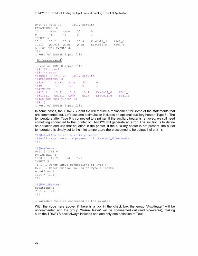
TRNSYS 16 – TRNEdit: Editing the Input File and Creating TRNSED Application
76�
UNIT 15 TYPE 25 Daily Results PARAMETERS 10 24 START STOP 33 0 0 -1 -1 0 1 INPUTS 6 13,1 13,2 13,3 13,4 EtaColl_d FSol_d IColl QuColl QDHW QAux EtaColl_d FSol_d ASSIGN "Daily.txt" 33 *|] … Rest of TRNSED input file
… Rest of TRNSED input file *|#*|[Printer1| *|#* Printer *|#UNIT 15 TYPE 25 Daily Results *|#PARAMETERS 10 *|#24 START STOP 33 0 *|#0 -1 -1 0 1 *|#INPUTS 6 *|#13,1 13,2 13,3 13,4 EtaColl_d FSol_d *|#IColl QuColl QDHW QAux EtaColl_d FSol_d *|#ASSIGN "Daily.txt" 33 *|#*|] … Rest of TRNSED input file
In some cases, the TRNSYS input file will require a replacement for some of the statements that are commented out. Let's assume a simulation includes an optional auxiliary heater (Type 6). The temperature after Type 6 is connected to a printer. If the auxiliary heater is removed, we still need something connected to that printer or TRNSYS will generate an error. The solution is to define an equation and use that equation in the printer. If the auxiliary heater is not present, the outlet temperature is simply set to the inlet temperature (here assumed to be output 1 of unit 1): *|{SelectAux|Select Auxiliary heater *|Auxilixary heater is present |AuxHeater|_NoAuxHeater *|} *|[AuxHeater| UNIT 2 TYPE 6 PARAMETERS 4 1000.0 4.19 0.0 1.0 INPUTS 5 [1,1] … Other Input connections of Type 6 0.0 … Other Initial values of Type 6 inputs equations 1 Tout = [2,1] *|] *|[NoAuxHeater| equations 1 Tout = [1,1] *|] … variable Tout is connected to the printer
With the code here above, if there is a tick in the check box the group "AuxHeater" will be uncommented and the group "NoAuxHeater" will be commented out (and vice-versa), making sure the TRNSYS deck always includes one and only one definition of Tout .
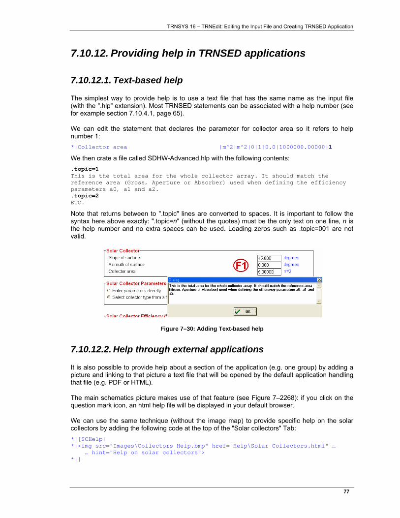
TRNSYS 16 – TRNEdit: Editing the Input File and Creating TRNSED Application
77�
7.10.12. Providing help in TRNSED applications
7.10.12.1. Text-based help
The simplest way to provide help is to use a text file that has the same name as the input file (with the ".hlp" extension). Most TRNSED statements can be associated with a help number (see for example section 7.10.4.1, page 65).
We can edit the statement that declares the parameter for collector area so it refers to help number 1: *|Collector area |m^2|m^2|0|1|0.0|1000000.00000|1
We then crate a file called SDHW-Advanced.hlp with the following contents: .topic=1 This is the total area for the whole collector array. It should match the reference area (Gross, Aperture or Absorber) used when defining the efficiency parameters a0, a1 and a2. .topic=2 ETC.
Note that returns between to ".topic" lines are converted to spaces. It is important to follow the syntax here above exactly: ".topic=n" (without the quotes) must be the only text on one line, n is the help number and no extra spaces can be used. Leading zeros such as .topic=001 are not valid.
Figure 7–30: Adding Text-based help
7.10.12.2. Help through external applications
It is also possible to provide help about a section of the application (e.g. one group) by adding a picture and linking to that picture a text file that will be opened by the default application handling that file (e.g. PDF or HTML).
The main schematics picture makes use of that feature (see Figure 7–2268): if you click on the question mark icon, an html help file will be displayed in your default browser.
We can use the same technique (without the image map) to provide specific help on the solar collectors by adding the following code at the top of the "Solar collectors" Tab: *|[SCHelp| *|<img src="Images\Collectors Help.bmp" href="Help\Solar Collectors.html" … … hint="Help on solar collectors"> *|]
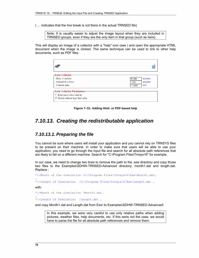
TRNSYS 16 – TRNEdit: Editing the Input File and Creating TRNSED Application
78�
( … indicates that the line break is not there in the actual TRNSED file)
Note: It is usually easier to adjust the image layout when they are included in TRNSED groups, even if they are the only item in that group (such as here).
This will display an image of a collector with a "help" icon (see ) and open the appropriate HTML document when the image is clicked. The same technique can be used to link to other help documents, such as PDF files.
Figure 7–31: Adding Html- or PDF-based help
7.10.13. Creating the redistributable application
7.10.13.1. Preparing the file
You cannot be sure where users will install your application and you cannot rely on TRNSYS files to be present on their machine. In order to make sure that users will be able to use your application, you need to go through the input file and search for all absolute path references that are likely to fail on a different machine. Search for "C:\Program Files\Trnsys16" for example.
In our case, we need to change two lines to remove the path to the .exe directory and copy those two files to the Examples\SDHW-TRNSED-Advanced directory: month1.dat and length.dat. Replace : *|<Month of the simulation |C:\Program Files\Trnsys16\Exe\Month1.dat… … *|<Length of Simulation |C:\Program Files\Trnsys16\Exe\Length.dat …
with: *|<Month of the simulation |Month1.dat… … *|<Length of Simulation |Length.dat …
and copy Month1.dat and Length.dat from Exe\ to Examples\SDHW-TRNSED-Advanced\
In this example, we were very careful to use only relative paths when adding pictures, weather files, help documents, etc. If this were not the case, we would have to parse the file for all absolute path references and remove them.
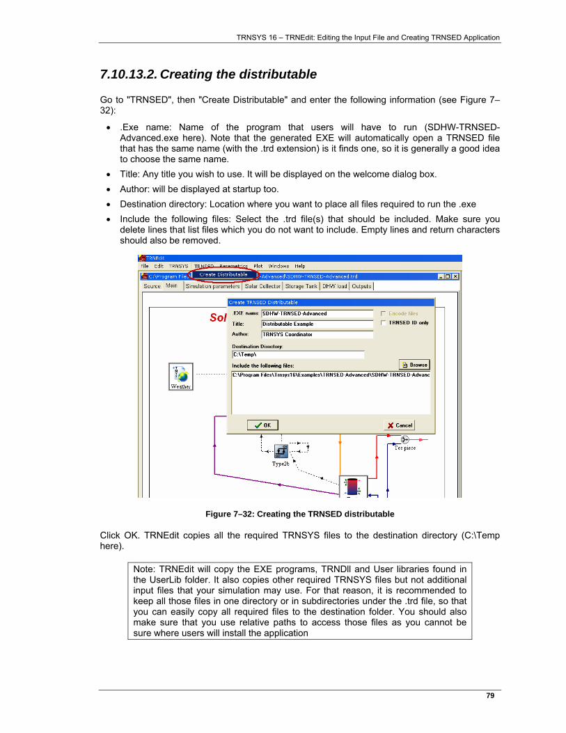
TRNSYS 16 – TRNEdit: Editing the Input File and Creating TRNSED Application
79�
7.10.13.2. Creating the distributable
Go to "TRNSED", then "Create Distributable" and enter the following information (see Figure 7–32):
• .Exe name: Name of the program that users will have to run (SDHW-TRNSED-Advanced.exe here). Note that the generated EXE will automatically open a TRNSED file that has the same name (with the .trd extension) is it finds one, so it is generally a good idea to choose the same name.
• Title: Any title you wish to use. It will be displayed on the welcome dialog box. • Author: will be displayed at startup too. • Destination directory: Location where you want to place all files required to run the .exe • Include the following files: Select the .trd file(s) that should be included. Make sure you
delete lines that list files which you do not want to include. Empty lines and return characters should also be removed.
Figure 7–32: Creating the TRNSED distributable
Click OK. TRNEdit copies all the required TRNSYS files to the destination directory (C:\Temp here).
Note: TRNEdit will copy the EXE programs, TRNDll and User libraries found in the UserLib folder. It also copies other required TRNSYS files but not additional input files that your simulation may use. For that reason, it is recommended to keep all those files in one directory or in subdirectories under the .trd file, so that you can easily copy all required files to the destination folder. You should also make sure that you use relative paths to access those files as you cannot be sure where users will install the application

TRNSYS 16 – TRNEdit: Editing the Input File and Creating TRNSED Application
80�
In our case, we just have to copy all subdirectories within Examples\TRNSED-Advanced\ to make sure that the simulation will find all the required files. Those subdirectories are: Data, Help, Images, Output, Weather.
After doing this, you can launch SDHW-TRNSED-Advanced.exe (or the name you gave to the exe).It is recommended that you test the distributable after moving the destination directory outside "C:\Program Files" and temporarily renaming your "C:\Program Files\Trnsys16" folder, in order to make sure that it is not using any file from your TRNSYS installation. Testing the application on another machine is also recommended.

TRNSYS 16 – TRNEdit: Editing the Input File and Creating TRNSED Application
81�
TRNSYS 16 – TRNEdit: Editing the Input File and Creating TRNSED Application
82�
7.11. TRNSED language reference
This section provides a systematic reference for TRNSED programmers. Few examples are provided and the reader is invited to refer to section 7.10 for more examples.
TRNSED relies on two basic features of the standard TRNSYS input file.
First, any line in a TRNSYS input file that begins with an asterisk (*) is interpreted by the TRNSYS equation solver as a comment. TRNSED can be thought of as a shell, interpreting these “comment” lines.
Second, any numerical value in a TRNSYS input file can be equated to an alpha-numeric name with the EQUATIONS or CONSTANTS statements as described in sections 7.3.8 and 7.3.9. TRNSED reads and changes the information on the EQUATIONS or CONSTANTS statements immediately preceding certain TRNSED command statements, thereby changing the numerical values that TRNSYS uses in the simulation. There are a number of different types of input fields available for inclusion in TRNSED programs including:
• Numerical Value Fields • Pull Down Menus • Radio Buttons • Check Boxes • Application Links through images and clickable areas in images
In addition, the TRNSED language provides means to control the layout of an input file, through font settings, object grouping, images and multiple tabs.
Note: All TRNSED statements are case insensitive
TRNSYS 16 – TRNEdit: Editing the Input File and Creating TRNSED Application
83�
7.11.1. Declaring the input file as a TRNSED file
A TRNSED input file is distinguished from a standard TRNSYS input file by 2 features:
• A .trd extension • A special statement on one of the first 5 lines:
*TRNSED
7.11.2. Format statements
7.11.2.1. Background
It is possible to set the background color of all TRNSED tabs with the instruction: *|<Background> color
where color is one of the following:
• BLACK, RED, BLUE, GREEN, GRAY, PURPLE, AQUA, YELLOW, SILVER, NAVY, FUCHSIA, LIME, WHITE, or DEF (default)
• An RGB value. RGB values are provided as triplets with the intensity of Red, Green and Blue on a scale from 0 to 255. For example (192,192,192) corresponds to the color Silver. The syntax is:
*|<Background> RGB(RedIntensity,GreenIntensity,BlueIntensity)
7.11.2.2. Images
It is possible to insert pictures at any point in the TRNSED input file. Please note, however, that the best graphical results are obtained when pictures are included within Groups (see section 7.10.5.1). The syntax to add an image is: *|<img src="Path to file\file name" align="alignValue">
where Path to file\file name is the full path- and filename of the picture and alignValue is one of the following: left (default), right, center
Only Windows Bitmaps (.bmp) can be used in TRNSED applications. Any image can be saved to a bitmap with simple programs such as MS Paint.
7.11.2.3. Text formatting
TRNSED uses 3 types of text in the input file:
• Text1: simple text. This text is not descriptive text for a certain input field or pull-down menu in the TRNSED window but appears only to present information and organize the display of the window. For example, simple text would be used to provide a title or other comments for the TRNSED display. The default for simple text is RED, BOLD, 12 point, Arial.
• Text2: Descriptive text. This is text associated with the input fields and pull-down menus appearing in the window and describes the meaning of the particular inputs. Descriptive text is that entered in the TRNSED Parameter and File Reference Statements to describe a particular input. The default for descriptive text is BLACK, 12 point, Arial
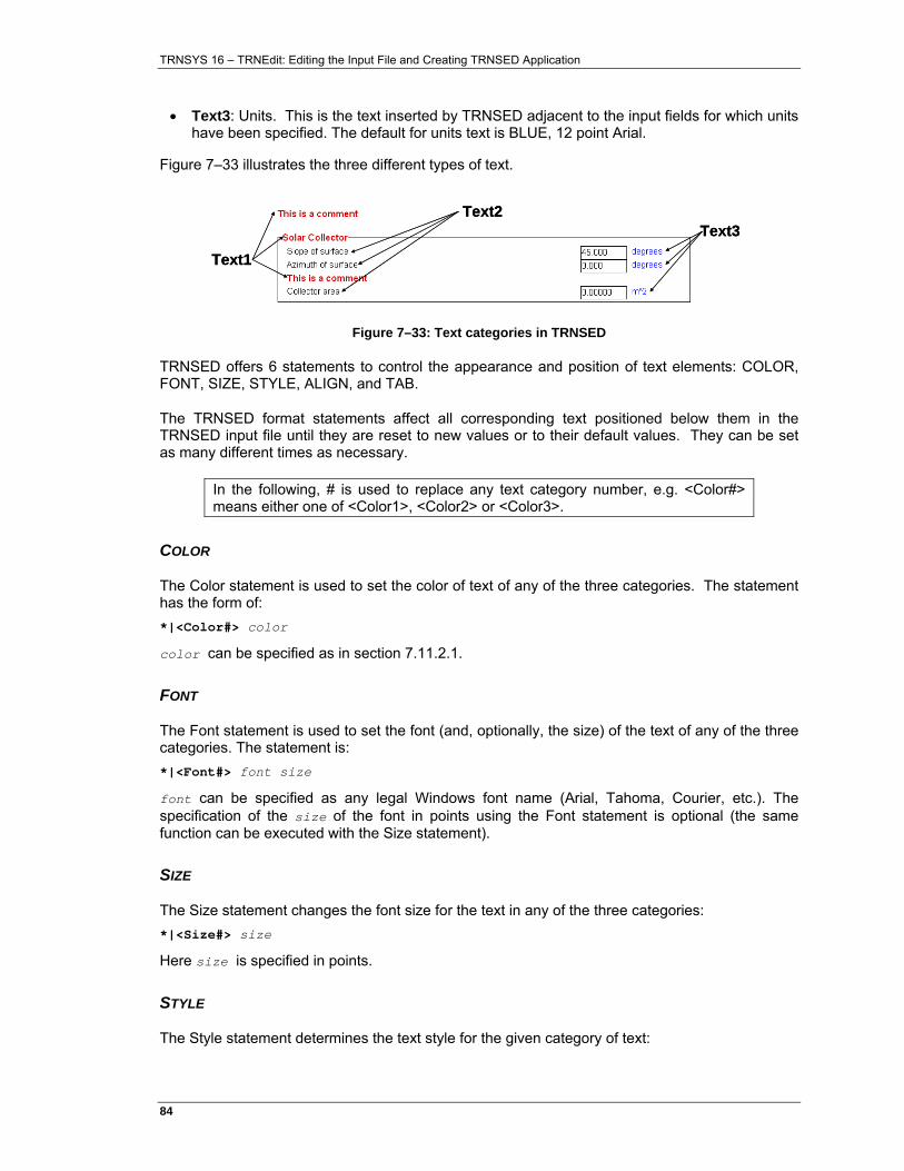
TRNSYS 16 – TRNEdit: Editing the Input File and Creating TRNSED Application
84�
• Text3: Units. This is the text inserted by TRNSED adjacent to the input fields for which units have been specified. The default for units text is BLUE, 12 point Arial.
Figure 7–33 illustrates the three different types of text.
Text1
Text2Text3
Text1
Text2Text3
Figure 7–33: Text categories in TRNSED
TRNSED offers 6 statements to control the appearance and position of text elements: COLOR, FONT, SIZE, STYLE, ALIGN, and TAB.
The TRNSED format statements affect all corresponding text positioned below them in the TRNSED input file until they are reset to new values or to their default values. They can be set as many different times as necessary.
In the following, # is used to replace any text category number, e.g. <Color#> means either one of <Color1>, <Color2> or <Color3>.
COLOR
The Color statement is used to set the color of text of any of the three categories. The statement has the form of: *|<Color#> color
color can be specified as in section 7.11.2.1.
FONT
The Font statement is used to set the font (and, optionally, the size) of the text of any of the three categories. The statement is: *|<Font#> font size
font can be specified as any legal Windows font name (Arial, Tahoma, Courier, etc.). The specification of the size of the font in points using the Font statement is optional (the same function can be executed with the Size statement).
SIZE
The Size statement changes the font size for the text in any of the three categories: *|<Size#> size
Here size is specified in points.
STYLE
The Style statement determines the text style for the given category of text:
TRNSYS 16 – TRNEdit: Editing the Input File and Creating TRNSED Application
85�
*|<Style#> style
Here style can be one or more of the following: Bold, Italic, Underline, None.
ALIGN
The Align statement determines the horizontal alignment of simple text (Text1) in the TRNSED window. The following is the correct form of the Align statement: *|<Align1> align
Here align can be assigned one of the following values: Left, right or center. Left will left-justify the text, Right will right-justify the text, and Center will center the text in the TRNSED window. Align can only be associated with simple text (not descriptive text or units)
TAB
The Tab statement determines the position of descriptive text (Text2) relative to the left side of the TRNSED window. The following is the correct form of the Tab statement: *|<Tab2> tab
Here tab can be specified in inches (in) or centimeters (cm) and is measured from the left side of the TRNSED window. If not specified in inches or centimeters, tab is taken to be measured in pixels. For example, the following statement would cause descriptive text to begin 3 inches from the left side of the TRNSED window: *|<Tab2> 3 in
The following statement will return to the default tab condition for descriptive text: *|<Tab2> def
Tab has an effect on both simple and descriptive text but not on units.
7.11.3. TRNSED Data Entry fields
There are a number of different types of data that TRNSED can read; simple values, items from pull-down menus, filenames, and simulation options (radio buttons and check boxes) to name a few. The next sections will take each type of data and explain the TRNSED syntax necessary for collecting such data.
7.11.3.1. Value input fields
The most fundamental type of TRNSED field is the numerical value field, in which a single value is required. It is the parameter statement which makes it possible for certain CONSTANTS and EQUATIONS statements from the TRNSYS input file to be edited from the user-friendly TRNSED input window.
Consider as an example a simulation of a solar domestic hot water system. Two key PARAMETERS which might be investigated with the simulation include FR(τα) and FRUL, which describe the collector performance. The experienced TRNSYS programmer would ordinarily enter numerical values for these PARAMETERS directly in the input file. As an alternative, these two PARAMETERS might be identified with variable names by placing the following EQUATIONS (or CONSTANTS) statement in the input file (see section 0 for more details):
TRNSYS 16 – TRNEdit: Editing the Input File and Creating TRNSED Application
86�
EQUATIONS 2 EFF = 0.7 FRUL = 14.3
The variable names defined in the CONSTANTS and EQUATIONS statements can be used anywhere in the TRNSYS input file in place of their corresponding numerical values. The use of CONSTANTS or EQUATIONS statements simplifies the process of changing values which might appear multiple times in the simulation input file and also makes the file more readable. TRNSED takes this process one step further by allowing the TRNSED programmer to display selected variables to the TRNSED end-user on a customized input screen.
The TRNSED numerical value field is created by adding a comment line into a TRNSYS deck immediately following the variable that is to be affected by the field. The syntax of the comment line is as follows: *|DescriptiveName|PrimaryUnits|SecondaryUnits|Add|Mult|Min|Max&Format|HelpNo
The first character is an asterisk so that TRNSYS interprets the statement as a comment. The second character is a vertical bar that denotes the line as a TRNSED statement. The remaining fields of the TRNSED statement are delimited by the vertical bar character and have the following interpretations:
• Descriptive Name - The text describing the meaning of the TRNSYS EQUATION or CONSTANT variable name. This field can contain up to 70 characters, including spaces. The text entered will have the format of Text2 and will appear first on the line
• Primary Units - A text string indicating the units that the TRNSYS program expects for this EQUATION or CONSTANT variable. The primary units are displayed when the File/Setup/TRNSED - ‘Primary Units’ button is chosen. The primary units should generally be the units required by the TRNSYS program.
• Secondary Units - A text string indicating a secondary unit system for this EQUATION or CONSTANT. The secondary unit system is displayed when the File/Setup/TRNSED - ‘Secondary Units’ button is chosen. The secondary unit system should be chosen with the end-user in mind.
• Add and Mult - Together, these two fields allow unit conversion between the primary and secondary unit systems. The formula for unit conversion is:
Secondary Unit Value = (Primary Unit Value + Add) * Mult
• Min - The minimum value that can be entered in the input box for the EQUATION or CONSTANT (in the primary unit system).
• Max & Format - The maximum allowable value (in the primary unit system) which TRNSED will accept as input. In addition, the format of this field controls the format of the display in the TRNSED window. If, for example, an input has a maximum value of 100 and the programmer wishes to display one decimal point, this field should be written as 100.0.
• Help No - A number which refers to one or more paragraphs of text information to be displayed in a window when the user requests help on this particular input field. Additional information on providing TRNSED help is presented later in this reference section.
For an example of value input field, see section 7.10.4.1, page 65.
7.11.3.2. Pull-down menu fields
Occasionally, it is convenient to have a TRNSYS input selected from a pull down menu of alternatives. When the user lands on a pull-down menu field, a dialog box appears with a
TRNSYS 16 – TRNEdit: Editing the Input File and Creating TRNSED Application
87�
scrollable list of alternatives from which the user may select. The choice that is left highlighted is set as the input. For an example of pull-down menu, see section 7.10.8, page 71.
The TRNSED syntax for adding a pull-down menu statement is: Variable = anyValue *|<Descriptive Text |FileName|Display Field |Value Field|HelpNo
The fields of the File Reference statement are separated with the vertical bar (|) character. The fields have the following interpretations:
• Variable = anyValue: Equation or constant statement that is located just above the File Reference statement. The value of "Value Field" for the line selected in the pull-down menu will replace anyValue.
• Name - text describing the TRNSYS input or PARAMETER. This is the text that describes the pull down menu, not text in the pull-down menu itself.
• File Name – The name (including path) of the ASCII text file containing the information required by TRNSED to produce a list.
• Display Field - the field number in which the text information that is to appear in the scrollable list is located. Fields are separated by a comma or tab character and begin with field 1. The city names in section 7.10.8 example are found in field 2 in the "Weather files.txt" file. If a 0 is entered in this position, then the item will not be displayed in the TRNSED window but its value will still be selected (see below).
• Value Field - the field number in which the numerical value associated with a selected text option is located. The city numbers are in field 1 for the above example. The Value Field corresponding to a selected text item from the Display Field will be inserted into the appropriate EQUATIONS or CONSTANTS statement in the TRNSYS input file (which must be right above the File Reference statement).
• HelpNo - a number which refers to one or more paragraphs of text information.
The format of the text file is as follows: The first line in this text file is the number of items in the list. Each following line contains two or more fields, separated by tabs or commas. The first input field should just be the line number, e.g.:
2 1 , Flat Plate (Low Performance) , 0.77 , 4.000 , 0.0250 , 0.2 , 0.0 2 , Flat Plate (Avg Performance) , 0.80 , 3.500 , 0.0125 , 0.2 , 0.0
(The number of lines is not limited)
HIDDEN FIELDS
In some cases it is desirable to set multiple EQUATIONS or CONSTANTS values from one menu choice. For an example, see section 7.10.9, page 72. The following TRNSED statements would allow to set PAR1 and PAR2 to the values in fields 1 and 3 of the data file, from one menu selection (assuming the field to be displayed in the pull-down menu is field 2, which matches the example in section 7.10.9): Equations 2 PAR1 = 0.0 *|<Descriptive Text PAR 1|FileName|2|1|HelpNo PAR2 = 0.0 *|<Descriptive Text PAR 2|FileName|0|3|HelpNo
The difference is that in the second input value field, a zero entered in the "Display Field" category indicates that nothing should be displayed. However, the "Value Field" does have entry and so the variable PAR2 would be set to the value in the third field of the data file. When more than one variable is set by a single menu selection, the second and subsequent variables are set
TRNSYS 16 – TRNEdit: Editing the Input File and Creating TRNSED Application
88�
based on TRNSED’s assessment of which line in the data file was selected for the first variable. The programmer should avoid creating pull-down menu data files with multiple lines having the same value in this primary field. For example, if there were more than one line with 1 in the first field, then incorrect values might be used for the subsequent TRNSED variables based on the first selection. As a side note, there is no need to include any descriptive text in fields that are not to be displayed.
7.11.3.3. TRNSED Assign statements
In almost all TRNSYS simulations, a number of files are assigned to logical unit numbers. There are two methods by which a TRNSED user can assign a file to an ASSIGN statement in the TRNSED input file. The two methods work in different situations. Each is described below.
ASSIGN "OPEN FILE" DIALOG BOX STATEMENT
The first method for allowing TRNSED users to access an ASSIGN statement in the input file is to use the ASSIGN "Open File" Dialog Box statement. When the user clicks on the TRNSED display box that contains the filename, the standard Windows "Open File" dialog box appears. The user can then either type in the desired filename or browse the computer file structure to select a filename. The syntax of the ASSIGN Open File Dialog Box statement is: ASSIGN "Path\File name.ext" LU *|? File description|HelpNo
The "?" character in column 3 identifies the ASSIGN Open File Dialog Box statement. File description is a text that will appear in front of the file name and help No has the usual meaning. For an example of Open file dialog box, see section 7.10.8, page 71. The file selected in the open dialog box will replace "Path\File name.ext" and be assigned to logical unit LU.
ASSIGN FILE REFERENCE STATEMENT
The second method is a special adaptation of the pull-down menu field. The user selects a filename (or description of a file) from a list and then this filename is placed into the ASSIGN statement which is just above the File Reference Statement. See section 7.10.8, page 71 for an example of File assignment through a pull-down menu. The ASSIGN File Reference Statement has the following format: ASSIGN "Path\File name.ext" LU *|<Descriptive Text |FileName|Display Field |Value Field|HelpNo
The file provided in "Value Field" for the row selected in the pull-down menu will replace "Path\File name.ext" and be assigned to logical unit LU. The other fields in this File Reference statement have the same meaning as those for the general pull-down menu statement described here above.
7.11.4. Grouping TRNSED statements
7.11.4.1. Multiple Tabs
The most visible new TRNSED feature in TRNSYS 16 is that the input fields can now be distributed across several tabs. See section 7.10.6, page 69, for an example of how multiple tabs are used.
TRNSYS 16 – TRNEdit: Editing the Input File and Creating TRNSED Application
89�
The syntax to create a new tab is: *|<TabWindow name="Tab name"> … TRNSED statements, groups, pertaining to this tab *|</TabWindow>
Tab name is a label that will appear on the tab. It is also used when adding links between tabs (see here below).
Notes:
• Everything that is before the opening statement of the first named tab or after the closing statement of the last tab will be placed in a default tab called "Main". The Main tab is always present.
• Tabs cannot be nested • Standard TRNSED groups (see here below) cannot span across different tabs • It is generally not recommended to have radio buttons and check boxes in one tab
controlling visible TRNSED groups in another tab.
7.11.4.2. Standard TRNSED Groups
Grouped statements appear encircled by a box, are labeled by descriptive text and are controlled as one unit by a TRNSED variable name. This ability makes it possible to include various system design options in a single TRNSED package. Groups are heavily used in the example presented in section 7.10, page 60.
The syntax for grouping a set of statements is as follows: *|[ GroupName | Optional Descriptive Text … TRNSED Statements appearing in Group *|]
GroupName is an internal name used by TRNSED control statements. If no descriptive text is included, the group will just be surrounded by a black line without any title.
Groups may have a different color than the background color. If you follow the group name with a |Background=color option, it will color the group as in the following example:
*|[ GroupName | Optional Descriptive Text | Background=yellow The program will accept the RGB color option as well, e.g.,
*|[ GroupName | Optional Descriptive Text | Background=rgb(104,100,0)
Note:
• Groups cannot be nested (Including with radio buttons and check boxes groups)
TRNSYS 16 – TRNEdit: Editing the Input File and Creating TRNSED Application
90�
7.11.4.3. Radio button group: Mutually exclusive options
Radio buttons can be used to select one alternative out of a list many. The syntax used to create a group of radio buttons is: *|( GroupName | Optional Text *| Descriptive Text for Radio Button 1 |GROUP1|GROUP2|…|_GROUP10 *| Descriptive Text for Radio Button 2 |GROUP1|_GROUP2|…|GROUP10 *| Descriptive Text for Radio Button 3 |_GROUP1|_GROUP2|…|_GROUP10 *|)
The list of group names (GROUP1, GROUP10 etc.) following each radio button description either comments in or comments out the group bearing that name. If an underscore ( _ ) precedes the group name, it will be commented out (and thus be ignored by TRNSYS). Otherwise, it will be commented in. When a group of TRNSED commands is commented out, it will not only be ignored during the TRNSYS simulation but will also disappear from the TRNSED input Window. There is a limit set of ten groups controlled by a single radio button. See section 7.10.10, page 74 for an example of radio buttons.
7.11.4.4. Check box group: non-exclusive options
Check boxes can be used when the user is allowed to choose any combination of options from a list. The syntax used to create a group of check boxes is: *|{ GroupName | Optional Text *| Descriptive Text for Check Box 1 |GROUP1|GROUP2|…|_GROUP10 *| Descriptive Text for Check Box 2 |GROUP1|_GROUP2|…|GROUP10 *| Descriptive Text for Check Box 3 |_GROUP1|_GROUP2|…|_GROUP10 *|}
The list of group names (GROUP1, GROUP10 etc.) following each check box description either comments in or comments out the group bearing that name. If an underscore ( _ ) precedes the group name, it will be commented out (and thus be ignored by TRNSYS). Otherwise, it will be commented in. When a group of TRNSED commands is commented out, it will not only be ignored during the TRNSYS simulation but will also disappear from the TRNSED input Window. There is a limit set of ten groups controlled by a single check box. See section 7.10.11, page 75, for an example of check boxes.
TRNSYS 16 – TRNEdit: Editing the Input File and Creating TRNSED Application
91�
7.11.5. Actions when an image is clicked
Each image defined with the *|<img … > tag in TRNSED can be associated with one or several actions when it is clicked. This is done using an "href" instruction, as described here below.
7.11.5.1. Links between tabs
Clicking on an image can make another tab active (bring it to the front). For an example of this, see section 7.10.6.2, page 69. The syntax is: *|<img src="Path\Image name.bmp" href="#Tab name" hint="descr. Text">
in the "href" instruction, the tab name is preceded with a pound sign (#) which means that "Tab name" is going to be the name of a TRNSED Tab and not a file name (see here below).
The text after "hint" will be displayed when the mouse is moved over the image, as a hint of what will happen if the image is clicked.
7.11.5.2. Links to external applications
Clicking on an image can launch an external application and open a file. For an example of this, see section 7.10.5.2, page 68. The syntax is: *|<img src="Path\Image name.bmp" href="File name.ext" hint="descr. Text">
"File name.ext" is the file that must be opened. TRNSED will launch the default windows application for that file type (and fail if no application is registered to handle such file).
The text after "hint" will be displayed when the mouse is moved over the image, as a hint of what will happen if the image is clicked.
7.11.5.3. Clickable areas in pictures ("hot spots")
With TRNSYS 16, it is now possible to associate several different actions with the same image. For an example of the power of this feature, combined with the multiple tabs, see the application created in section 7.10, page 60 (and more specifically section 7.10.7). Where, in TRNSYS 15, users would have faced a very tall window with many groups, the TRNSYS 16 version of that file presents a much more user-friendly view with short tabs referenced from a main system schematic.
The principle is similar to the HTML "usemap" feature to define clickable areas, except that only rectangles can be defined. In order to associate a map with an image, the following syntax must be used: *|<img src="Path\Img name.bmp" usemap="Path to \Map.txt">
Where "Path to \Map.txt" is the full path to the image map. No "href" or "hint" instruction should be present in an image that uses a map, since those instructions will be in the map itself.
TRNSYS 16 – TRNEdit: Editing the Input File and Creating TRNSED Application
92�
The map itself is defined in a text file that must have the following syntax:
! Optional comments start with an exclamation mark <area href="#Tab name" coords="x-left,y-upper,x-right,y-lower" hint="hint"> … <area href="File name.ext" coords="x-left,y-upper,x-right,y-lower" hint="hint"> …
Each line (except for comment lines starting with an exclamation mark) defines a rectangle and the action that should be taken when the mouse is clicked in that rectangle (in addition to a "hint" displayed when the mouse pointer is moved over the rectangle). The links indicated by the href="…" statements can be to external files as well as tabs in the TRNSED application (in the latter case, they should start with a #.
The "coords" keyword introduces the rectangle coordinates in pixels (the upper left corner is (1,1)):
• x-left is the x-value (value along horizontal axis, left to right is >0) of the left corners • y-upper is the y-value (value along vertical axis, down is >0) of the upper corners • x-right is the x-value (value along horizontal axis, left to right is >0) of the right corners • y-lower is the y-value (value along vertical axis, down is >0) of the lower corners
7.11.6. Pre- and post-processing actions
The TRNSED statements <BEFORE> and <AFTER> allow the TRNSED programmer to specify command line (DOS) statements which will be executed before and after the TRNSED input file is run by TRNSYS, respectively. The syntax for the statements is as follows: *|<BEFORE> statement *|<AFTER> statement
where statement is a command line to be executed. Note that TRNSED will start the program in the directory where the executable (TRNEdit.exe or the executable generated by the "Create distributable" command) is located.
Example: *|<BEFORE> MyPreprocessing.exe ThisInputFile.dck
When running a Parametric Table, TRNEDIT will execute the directives <BEFORE> and <AFTER> before and after EACH TRNSYS run, correspondingly. The statements <BEFORE1> and <AFTER1> will only run ONCE before and after the Parametric Table calculations.
TRNSYS 16 – TRNEdit: Editing the Input File and Creating TRNSED Application
93�
7.11.7. Providing help in TRNSED
7.11.7.1. Help as HTML, PDF, etc. documents
The most flexible way to provide help is TRNSED is by using the ability of images to launch external applications: you can easily open HTML- or PDF- based help files from any image. See section 7.10.12.2, page 77, for an example.
7.11.7.2. Text-based help
Another method to provide help is to use text-based help topics that can be associated to any TRNSED input field. The help information is entered into an external help file with an .hlp extension and a prefix matching that of the TRNSED input file. For example, the help file for the input file called sdhw.trd should be sdhw.hlp. This .hlp file is simply a text file and should reside in the same directory as the corresponding TRNSED input file. To properly implement an .hlp file, follow the steps below:
• Supply a unique help number to each TRNSED Parameter or File Reference statement in the input file. For the example shown below, 2 is the help number.
EFF = 0.7 *|Intercept Efficiency |-|-|0.0|1.0|0.0|1.00|2
• Open the help file for editing. This file should have the same name as the input file but with a .hlp extension.
• Add the desired help text to the .hlp file. The required help entry syntax is that all text must be after a line having the text ".topic=n" where n is the help number. All text information between .topic lines will be displayed as context-sensitive help information.
See section 7.10.12.1, page 77, for an example.
7.11.8. Using TRNSED Index Files (.idx)
As described in Section 7.12.4.1, page 101, a TRNSED-based distributable application can have any name for the .exe program and that .exe program will open a .trd file with the same name if one is present in the same directory. This is the most convenient way to proceed if your TRNSED application is intended to be used with one input file.
If the same application is meant to be used with different input files, you can provide an index to the different input files that are available. That index is located in a file that must have the same name as the executable but an .idx extension.
The contents of the .idx file are: Title Author Institution First Demo description demo1.trd picture1.bmp helptext1.txt Second Demo description demo2.trd picture2.bmp helptext2.txt Third Demo description demo3.trd picture3.bmp helptext3.txt …Etc.
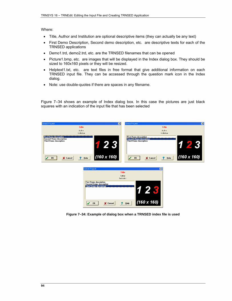
TRNSYS 16 – TRNEdit: Editing the Input File and Creating TRNSED Application
94�
Where:
• Title, Author and Institution are optional descriptive items (they can actually be any text) • First Demo Description, Second demo description, etc. are descriptive texts for each of the
TRNSED applications • Demo1.trd, demo2.trd, etc. are the TRNSED filenames that can be opened • Picture1.bmp, etc. are images that will be displayed in the Index dialog box. They should be
sized to 160x160 pixels or they will be resized. • Helptext1.txt, etc. are text files in free format that give additional information on each
TRNSED input file. They can be accessed through the question mark icon in the Index dialog.
• Note: use double-quotes if there are spaces in any filename.
Figure 7–34 shows an example of Index dialog box. In this case the pictures are just black squares with an indication of the input file that has been selected
Figure 7–34: Example of dialog box when a TRNSED index file is used

TRNSYS 16 – TRNEdit: Editing the Input File and Creating TRNSED Application
95�
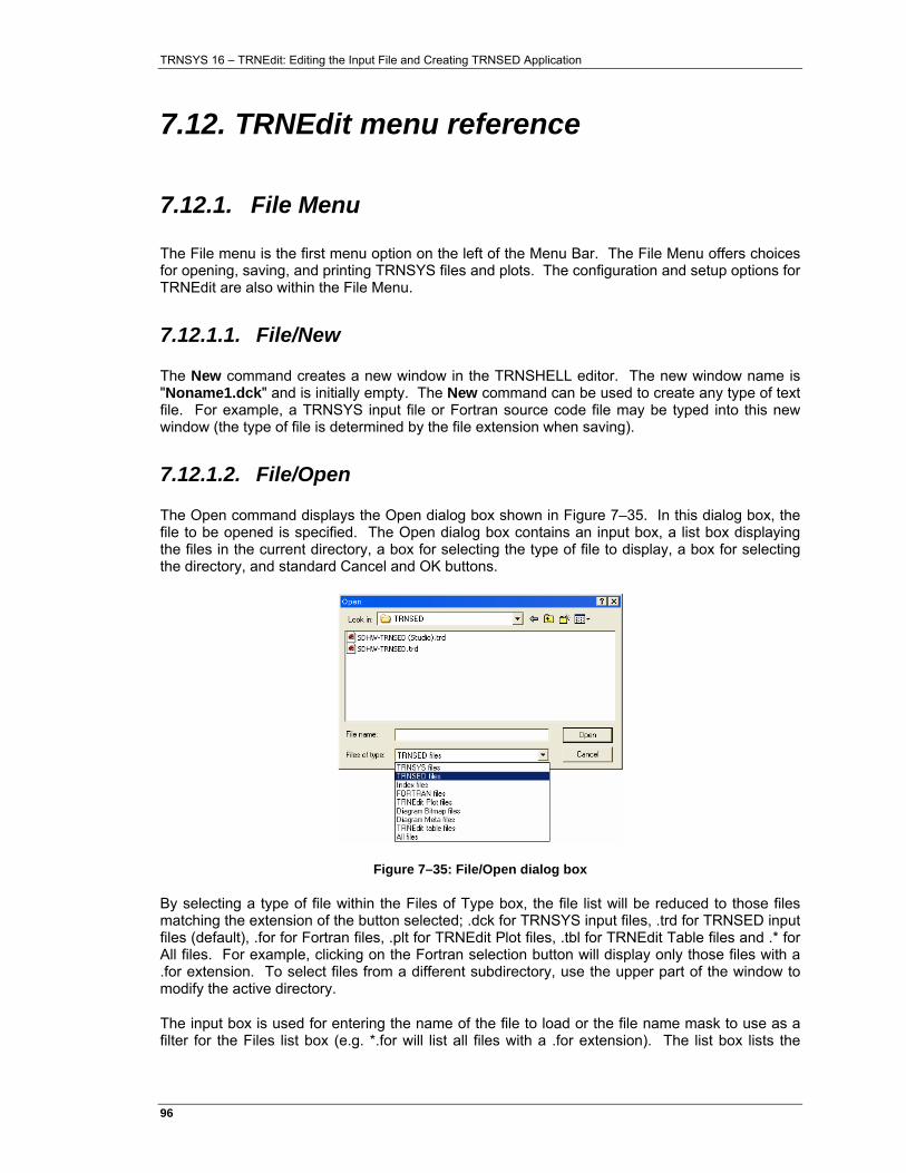
TRNSYS 16 – TRNEdit: Editing the Input File and Creating TRNSED Application
96�
7.12. TRNEdit menu reference
7.12.1. File Menu
The File menu is the first menu option on the left of the Menu Bar. The File Menu offers choices for opening, saving, and printing TRNSYS files and plots. The configuration and setup options for TRNEdit are also within the File Menu.
7.12.1.1. File/New
The New command creates a new window in the TRNSHELL editor. The new window name is "Noname1.dck" and is initially empty. The New command can be used to create any type of text file. For example, a TRNSYS input file or Fortran source code file may be typed into this new window (the type of file is determined by the file extension when saving).
7.12.1.2. File/Open
The Open command displays the Open dialog box shown in Figure 7–35. In this dialog box, the file to be opened is specified. The Open dialog box contains an input box, a list box displaying the files in the current directory, a box for selecting the type of file to display, a box for selecting the directory, and standard Cancel and OK buttons.
Figure 7–35: File/Open dialog box
By selecting a type of file within the Files of Type box, the file list will be reduced to those files matching the extension of the button selected; .dck for TRNSYS input files, .trd for TRNSED input files (default), .for for Fortran files, .plt for TRNEdit Plot files, .tbl for TRNEdit Table files and .* for All files. For example, clicking on the Fortran selection button will display only those files with a .for extension. To select files from a different subdirectory, use the upper part of the window to modify the active directory.
The input box is used for entering the name of the file to load or the file name mask to use as a filter for the Files list box (e.g. *.for will list all files with a .for extension). The list box lists the
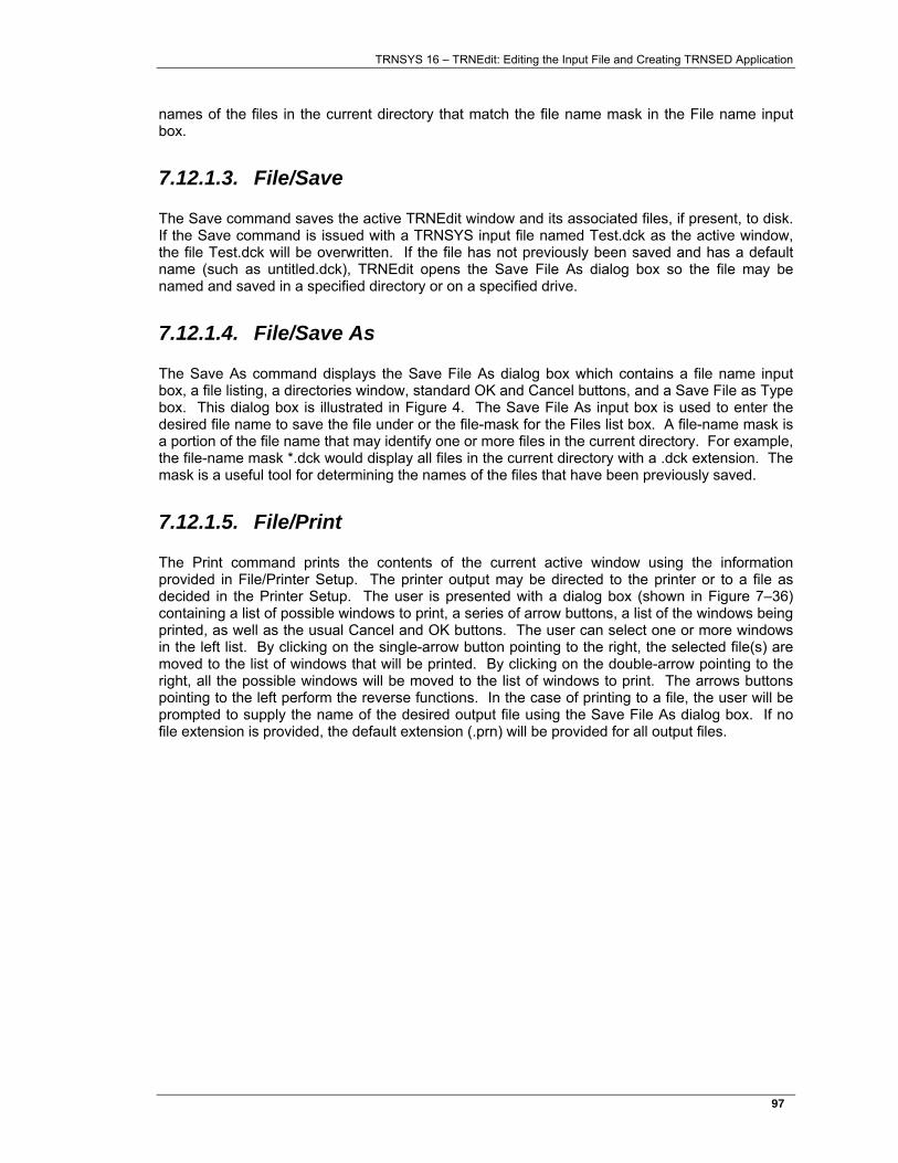
TRNSYS 16 – TRNEdit: Editing the Input File and Creating TRNSED Application
97�
names of the files in the current directory that match the file name mask in the File name input box.
7.12.1.3. File/Save
The Save command saves the active TRNEdit window and its associated files, if present, to disk. If the Save command is issued with a TRNSYS input file named Test.dck as the active window, the file Test.dck will be overwritten. If the file has not previously been saved and has a default name (such as untitled.dck), TRNEdit opens the Save File As dialog box so the file may be named and saved in a specified directory or on a specified drive.
7.12.1.4. File/Save As
The Save As command displays the Save File As dialog box which contains a file name input box, a file listing, a directories window, standard OK and Cancel buttons, and a Save File as Type box. This dialog box is illustrated in Figure 4. The Save File As input box is used to enter the desired file name to save the file under or the file-mask for the Files list box. A file-name mask is a portion of the file name that may identify one or more files in the current directory. For example, the file-name mask *.dck would display all files in the current directory with a .dck extension. The mask is a useful tool for determining the names of the files that have been previously saved.
7.12.1.5. File/Print
The Print command prints the contents of the current active window using the information provided in File/Printer Setup. The printer output may be directed to the printer or to a file as decided in the Printer Setup. The user is presented with a dialog box (shown in Figure 7–36) containing a list of possible windows to print, a series of arrow buttons, a list of the windows being printed, as well as the usual Cancel and OK buttons. The user can select one or more windows in the left list. By clicking on the single-arrow button pointing to the right, the selected file(s) are moved to the list of windows that will be printed. By clicking on the double-arrow pointing to the right, all the possible windows will be moved to the list of windows to print. The arrows buttons pointing to the left perform the reverse functions. In the case of printing to a file, the user will be prompted to supply the name of the desired output file using the Save File As dialog box. If no file extension is provided, the default extension (.prn) will be provided for all output files.
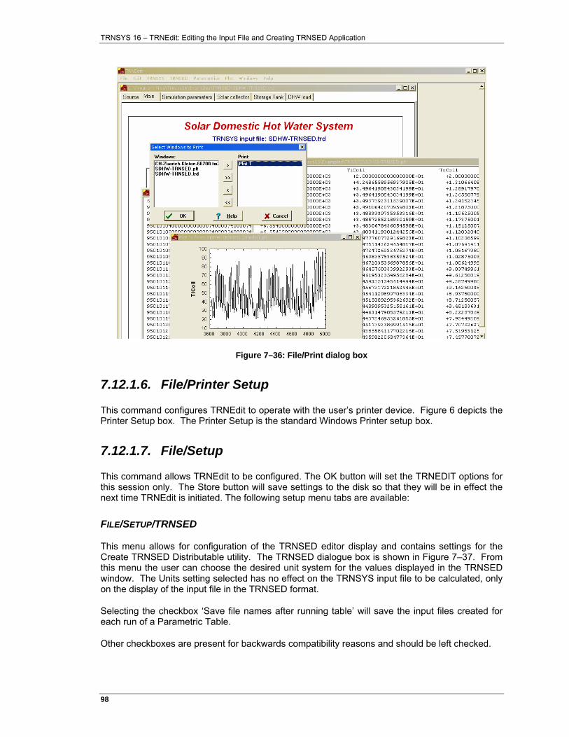
TRNSYS 16 – TRNEdit: Editing the Input File and Creating TRNSED Application
98�
Figure 7–36: File/Print dialog box
7.12.1.6. File/Printer Setup
This command configures TRNEdit to operate with the user’s printer device. Figure 6 depicts the Printer Setup box. The Printer Setup is the standard Windows Printer setup box.
7.12.1.7. File/Setup
This command allows TRNEdit to be configured. The OK button will set the TRNEDIT options for this session only. The Store button will save settings to the disk so that they will be in effect the next time TRNEdit is initiated. The following setup menu tabs are available:
FILE/SETUP/TRNSED
This menu allows for configuration of the TRNSED editor display and contains settings for the Create TRNSED Distributable utility. The TRNSED dialogue box is shown in Figure 7–37. From this menu the user can choose the desired unit system for the values displayed in the TRNSED window. The Units setting selected has no effect on the TRNSYS input file to be calculated, only on the display of the input file in the TRNSED format.
Selecting the checkbox ‘Save file names after running table’ will save the input files created for each run of a Parametric Table.
Other checkboxes are present for backwards compatibility reasons and should be left checked.
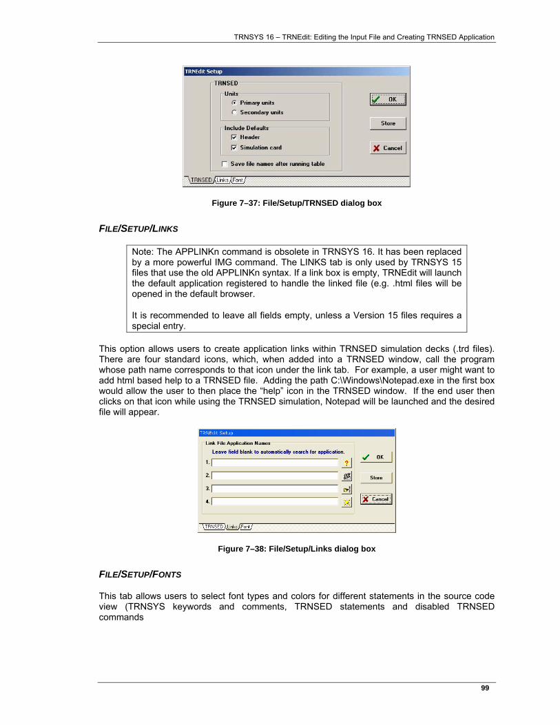
TRNSYS 16 – TRNEdit: Editing the Input File and Creating TRNSED Application
99�
Figure 7–37: File/Setup/TRNSED dialog box
FILE/SETUP/LINKS
Note: The APPLINKn command is obsolete in TRNSYS 16. It has been replaced by a more powerful IMG command. The LINKS tab is only used by TRNSYS 15 files that use the old APPLINKn syntax. If a link box is empty, TRNEdit will launch the default application registered to handle the linked file (e.g. .html files will be opened in the default browser.
It is recommended to leave all fields empty, unless a Version 15 files requires a special entry.
This option allows users to create application links within TRNSED simulation decks (.trd files). There are four standard icons, which, when added into a TRNSED window, call the program whose path name corresponds to that icon under the link tab. For example, a user might want to add html based help to a TRNSED file. Adding the path C:\Windows\Notepad.exe in the first box would allow the user to then place the “help” icon in the TRNSED window. If the end user then clicks on that icon while using the TRNSED simulation, Notepad will be launched and the desired file will appear.
Figure 7–38: File/Setup/Links dialog box
FILE/SETUP/FONTS
This tab allows users to select font types and colors for different statements in the source code view (TRNSYS keywords and comments, TRNSED statements and disabled TRNSED commands
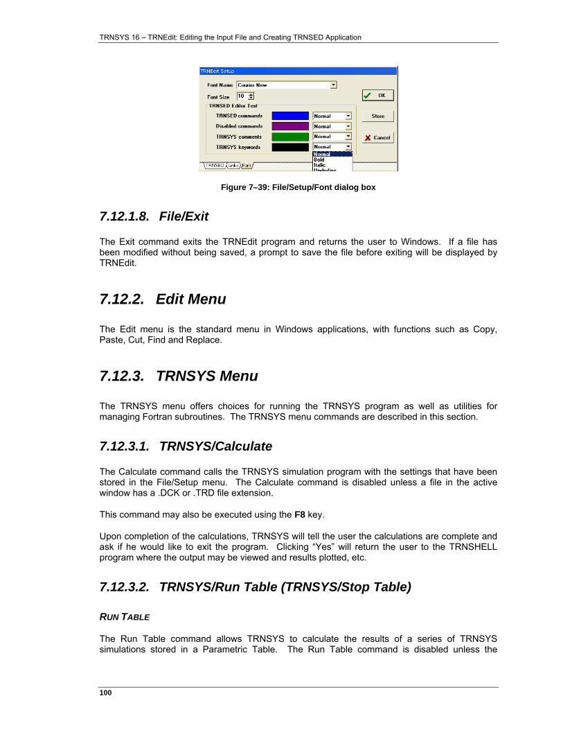
TRNSYS 16 – TRNEdit: Editing the Input File and Creating TRNSED Application
100�
Figure 7–39: File/Setup/Font dialog box
7.12.1.8. File/Exit
The Exit command exits the TRNEdit program and returns the user to Windows. If a file has been modified without being saved, a prompt to save the file before exiting will be displayed by TRNEdit.
7.12.2. Edit Menu
The Edit menu is the standard menu in Windows applications, with functions such as Copy, Paste, Cut, Find and Replace.
7.12.3. TRNSYS Menu
The TRNSYS menu offers choices for running the TRNSYS program as well as utilities for managing Fortran subroutines. The TRNSYS menu commands are described in this section.
7.12.3.1. TRNSYS/Calculate
The Calculate command calls the TRNSYS simulation program with the settings that have been stored in the File/Setup menu. The Calculate command is disabled unless a file in the active window has a .DCK or .TRD file extension.
This command may also be executed using the F8 key.
Upon completion of the calculations, TRNSYS will tell the user the calculations are complete and ask if he would like to exit the program. Clicking “Yes” will return the user to the TRNSHELL program where the output may be viewed and results plotted, etc.
7.12.3.2. TRNSYS/Run Table (TRNSYS/Stop Table)
RUN TABLE
The Run Table command allows TRNSYS to calculate the results of a series of TRNSYS simulations stored in a Parametric Table. The Run Table command is disabled unless the
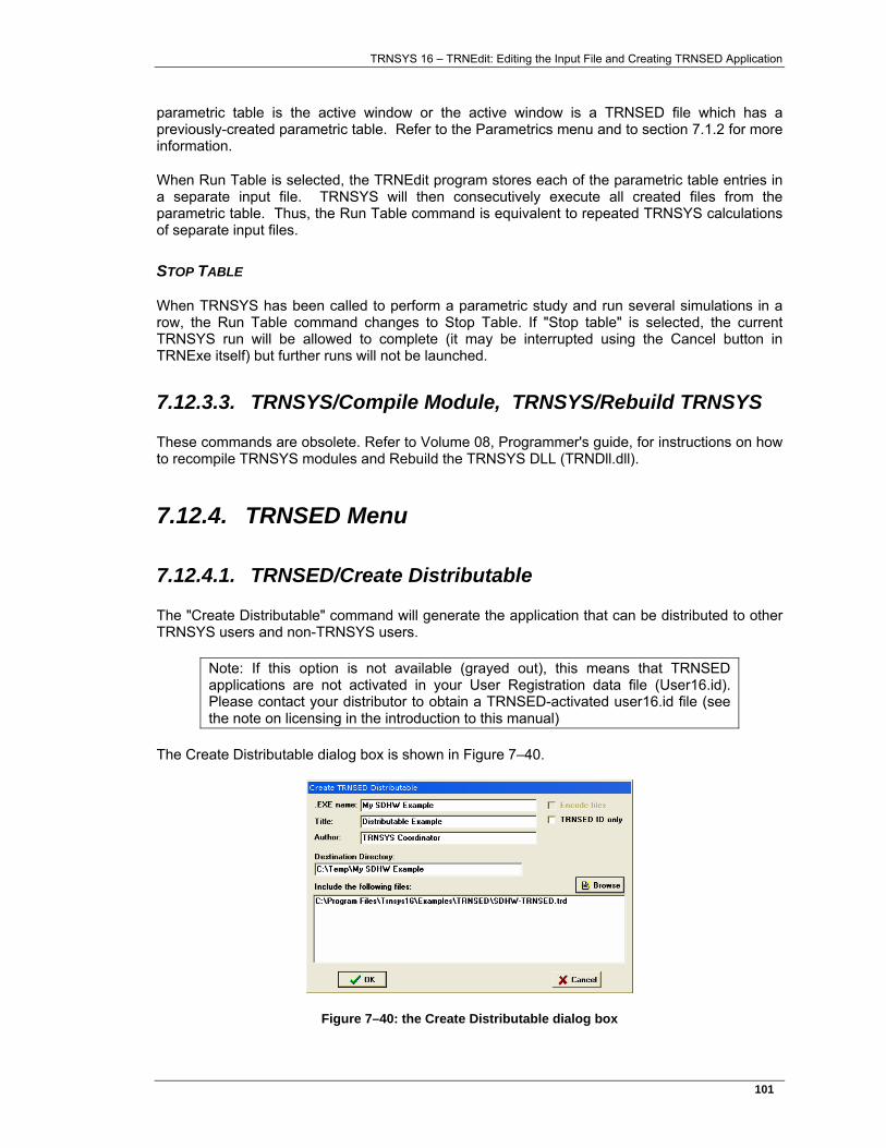
TRNSYS 16 – TRNEdit: Editing the Input File and Creating TRNSED Application
101�
parametric table is the active window or the active window is a TRNSED file which has a previously-created parametric table. Refer to the Parametrics menu and to section 7.1.2 for more information.
When Run Table is selected, the TRNEdit program stores each of the parametric table entries in a separate input file. TRNSYS will then consecutively execute all created files from the parametric table. Thus, the Run Table command is equivalent to repeated TRNSYS calculations of separate input files.
STOP TABLE
When TRNSYS has been called to perform a parametric study and run several simulations in a row, the Run Table command changes to Stop Table. If "Stop table" is selected, the current TRNSYS run will be allowed to complete (it may be interrupted using the Cancel button in TRNExe itself) but further runs will not be launched.
7.12.3.3. TRNSYS/Compile Module, TRNSYS/Rebuild TRNSYS
These commands are obsolete. Refer to Volume 08, Programmer's guide, for instructions on how to recompile TRNSYS modules and Rebuild the TRNSYS DLL (TRNDll.dll).
7.12.4. TRNSED Menu
7.12.4.1. TRNSED/Create Distributable
The "Create Distributable" command will generate the application that can be distributed to other TRNSYS users and non-TRNSYS users.
Note: If this option is not available (grayed out), this means that TRNSED applications are not activated in your User Registration data file (User16.id). Please contact your distributor to obtain a TRNSED-activated user16.id file (see the note on licensing in the introduction to this manual)
The Create Distributable dialog box is shown in Figure 7–40.
Figure 7–40: the Create Distributable dialog box
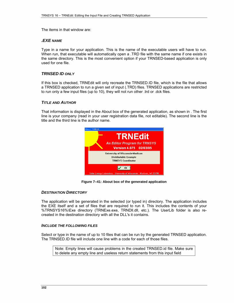
TRNSYS 16 – TRNEdit: Editing the Input File and Creating TRNSED Application
102�
The items in that window are:
.EXE NAME
Type in a name for your application. This is the name of the executable users will have to run. When run, that executable will automatically open a .TRD file with the same name if one exists in the same directory. This is the most convenient option if your TRNSED-based application is only used for one file.
TRNSED ID ONLY
If this box is checked, TRNEdit will only recreate the TRNSED.ID file, which is the file that allows a TRNSED application to run a given set of input (.TRD) files. TRNSED applications are restricted to run only a few input files (up to 10), they will not run other .trd or .dck files.
TITLE AND AUTHOR
That information is displayed in the About box of the generated application, as shown in . The first line is your company (read in your user registration data file, not editable). The second line is the title and the third line is the author name.
Figure 7–41: About box of the generated application
DESTINATION DIRECTORY
The application will be generated in the selected (or typed in) directory. The application includes the EXE itself and a set of files that are required to run it. This includes the contents of your %TRNSYS16%\Exe directory (TRNExe.exe, TRNDll.dll, etc.). The UserLib folder is also re-created in the destination directory with all the DLL's it contains.
INCLUDE THE FOLLOWING FILES
Select or type in the name of up to 10 files that can be run by the generated TRNSED application. The TRNSED.ID file will include one line with a code for each of those files.
Note: Empty lines will cause problems in the created TRNSED.id file. Make sure to delete any empty line and useless return statements from this input field
TRNSYS 16 – TRNEdit: Editing the Input File and Creating TRNSED Application
103�
7.12.5. Parametrics Menu
The Parametrics menu contains commands to set up and modify the data in a parametric table. The parametric table operates in a manner similar to a spreadsheet. The power of the parametric table is that it allows the user to execute repetitive TRNSYS simulations using one input file with different values of system variables.
7.12.5.1. Performing parametric studies in TRNSYS
The parametric table option allows users to choose any variable that is defined in the input file with a CONSTANTS command and add it to a parametric table. Variables that are defined with EQUATIONS commands cannot be inserted into a parametric table. Because of the distinction between CONSTANTS and EQUATIONS, programmers may specify which variables can be selected for inclusion in a parametric table. Neither TRNSYS nor TRNSED care whether a variable was defined using an EQUATIONS or CONSTANTS command, only the Parametrics function does. If a programmer wishes to exclude some of these variables from possible inclusion in a table, the CONSTANTS specification could be replaced with an EQUATIONS specification.
The parametric table works in the following way. If the original input file is named File.dck, N files with the names File1.TMP, File2.TMP, ..., FileN.TMP are created in the current directory, where N is the number of runs in the parametric table. Each file has a different set of values corresponding to the ones specified in the parametric table. Also, the ASSIGN statements for the TRNSYS output file(s), TRNSYS listing file and TRNSYS plot file are corrected according to the new file name. Only ASSIGN statements that use the same filename as the input file (with a different extension) are affected. This includes the automatic filenames such as ***.out. Other Filenames are not affected.
For example, consider an input file named "MyFile.dck" that reads the weather data from "US-CA-San-Francisco-23234.tm2", outputs a set of variables through a printer to "***.out", another set of variables through an online plotter to "***.plt" and finally simulation results to "Totals.txt" through another Type 25 (printer) unit.
If 10 parametric runs are executed, MyFile1.tmp to MyFile10.tmp will be generated with the appropriate values of parameters. All of them will read the weather data from "US-CA-San-Francisco-23234.tm2". All of them will also write to "Totals.txt" (and that printer could be configured to append to the file rather than rewrite it), but each run will generate a different .out and .plt file: MyDeck1.out, MyDeck2.out, etc. and MyDeck1.plt, MyDeck2.plt, etc.
Because of the parametric table naming convention, users should refrain from ending the names of TRNSYS input files with a number. For example, if a user had an input file named FILE11.TRD, the automatically renamed output files from this input file would be deleted if a user ran a 11 row parametric table of an input file named FILE.TRD since the 11th run would be named FILE11.
All cells of the parametric table must be filled before running the table.
7.12.5.2. Parametrics/New Table
The number of runs, which corresponds to the number of rows in the table, is entered in the box at the top of the New Parametric Table dialog window (see Figure 7–4, page 15). The list of variables available to put in the table appears on the left. This list contains the names of all
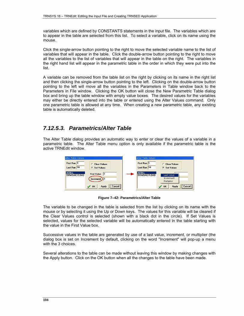
TRNSYS 16 – TRNEdit: Editing the Input File and Creating TRNSED Application
104�
variables which are defined by CONSTANTS statements in the input file. The variables which are to appear in the table are selected from this list. To select a variable, click on its name using the mouse.
Click the single-arrow button pointing to the right to move the selected variable name to the list of variables that will appear in the table. Click the double-arrow button pointing to the right to move all the variables to the list of variables that will appear in the table on the right. The variables in the right hand list will appear in the parametric table in the order in which they were put into the list.
A variable can be removed from the table list on the right by clicking on its name in the right list and then clicking the single-arrow button pointing to the left. Clicking on the double-arrow button pointing to the left will move all the variables in the Parameters in Table window back to the Parameters in File window. Clicking the OK button will close the New Parametric Table dialog box and bring up the table window with empty value boxes. The desired values for the variables may either be directly entered into the table or entered using the Alter Values command. Only one parametric table is allowed at any time. When creating a new parametric table, any existing table is automatically deleted.
7.12.5.3. Parametrics/Alter Table
The Alter Table dialog provides an automatic way to enter or clear the values of a variable in a parametric table. The Alter Table menu option is only available if the parametric table is the active TRNEdit window.
Figure 7–42: Parametrics/Alter Table
The variable to be changed in the table is selected from the list by clicking on its name with the mouse or by selecting it using the Up or Down keys. The values for this variable will be cleared if the Clear Values control is selected (shown with a black dot in the circle). If Set Values is selected, values for the selected variable will be automatically entered in the table starting with the value in the First Value box.
Successive values in the table are generated by use of a last value, increment, or multiplier (the dialog box is set on Increment by default, clicking on the word "Increment" will pop-up a menu with the 3 choices.
Several alterations to the table can be made without leaving this window by making changes with the Apply button. Click on the OK button when all the changes to the table have been made.
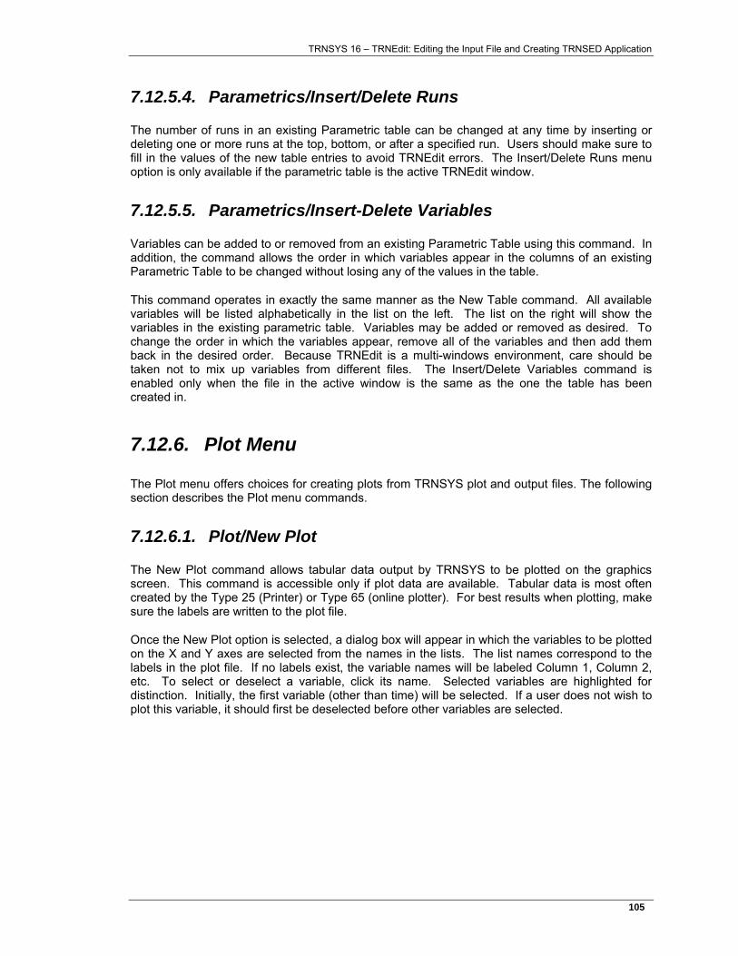
TRNSYS 16 – TRNEdit: Editing the Input File and Creating TRNSED Application
105�
7.12.5.4. Parametrics/Insert/Delete Runs
The number of runs in an existing Parametric table can be changed at any time by inserting or deleting one or more runs at the top, bottom, or after a specified run. Users should make sure to fill in the values of the new table entries to avoid TRNEdit errors. The Insert/Delete Runs menu option is only available if the parametric table is the active TRNEdit window.
7.12.5.5. Parametrics/Insert-Delete Variables
Variables can be added to or removed from an existing Parametric Table using this command. In addition, the command allows the order in which variables appear in the columns of an existing Parametric Table to be changed without losing any of the values in the table.
This command operates in exactly the same manner as the New Table command. All available variables will be listed alphabetically in the list on the left. The list on the right will show the variables in the existing parametric table. Variables may be added or removed as desired. To change the order in which the variables appear, remove all of the variables and then add them back in the desired order. Because TRNEdit is a multi-windows environment, care should be taken not to mix up variables from different files. The Insert/Delete Variables command is enabled only when the file in the active window is the same as the one the table has been created in.
7.12.6. Plot Menu
The Plot menu offers choices for creating plots from TRNSYS plot and output files. The following section describes the Plot menu commands.
7.12.6.1. Plot/New Plot
The New Plot command allows tabular data output by TRNSYS to be plotted on the graphics screen. This command is accessible only if plot data are available. Tabular data is most often created by the Type 25 (Printer) or Type 65 (online plotter). For best results when plotting, make sure the labels are written to the plot file.
Once the New Plot option is selected, a dialog box will appear in which the variables to be plotted on the X and Y axes are selected from the names in the lists. The list names correspond to the labels in the plot file. If no labels exist, the variable names will be labeled Column 1, Column 2, etc. To select or deselect a variable, click its name. Selected variables are highlighted for distinction. Initially, the first variable (other than time) will be selected. If a user does not wish to plot this variable, it should first be deselected before other variables are selected.
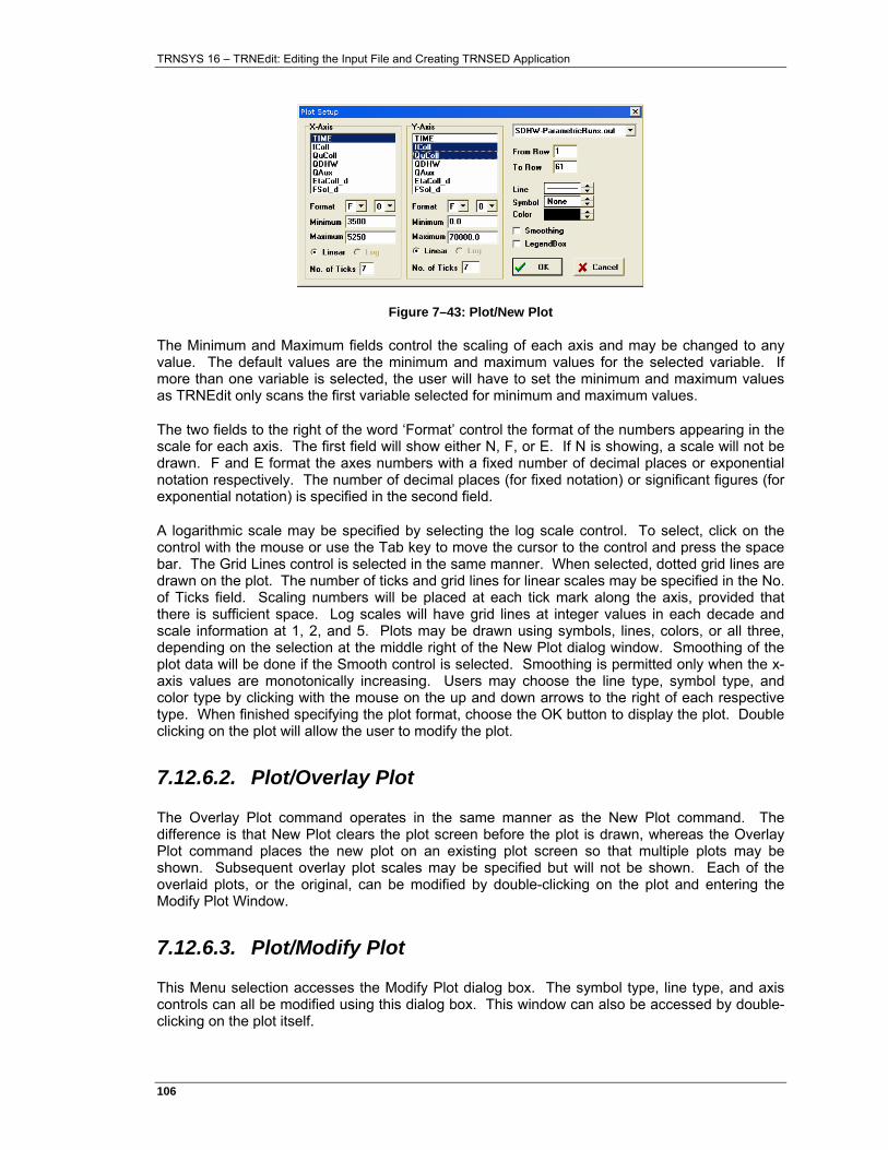
TRNSYS 16 – TRNEdit: Editing the Input File and Creating TRNSED Application
106�
Figure 7–43: Plot/New Plot
The Minimum and Maximum fields control the scaling of each axis and may be changed to any value. The default values are the minimum and maximum values for the selected variable. If more than one variable is selected, the user will have to set the minimum and maximum values as TRNEdit only scans the first variable selected for minimum and maximum values.
The two fields to the right of the word ‘Format’ control the format of the numbers appearing in the scale for each axis. The first field will show either N, F, or E. If N is showing, a scale will not be drawn. F and E format the axes numbers with a fixed number of decimal places or exponential notation respectively. The number of decimal places (for fixed notation) or significant figures (for exponential notation) is specified in the second field.
A logarithmic scale may be specified by selecting the log scale control. To select, click on the control with the mouse or use the Tab key to move the cursor to the control and press the space bar. The Grid Lines control is selected in the same manner. When selected, dotted grid lines are drawn on the plot. The number of ticks and grid lines for linear scales may be specified in the No. of Ticks field. Scaling numbers will be placed at each tick mark along the axis, provided that there is sufficient space. Log scales will have grid lines at integer values in each decade and scale information at 1, 2, and 5. Plots may be drawn using symbols, lines, colors, or all three, depending on the selection at the middle right of the New Plot dialog window. Smoothing of the plot data will be done if the Smooth control is selected. Smoothing is permitted only when the x-axis values are monotonically increasing. Users may choose the line type, symbol type, and color type by clicking with the mouse on the up and down arrows to the right of each respective type. When finished specifying the plot format, choose the OK button to display the plot. Double clicking on the plot will allow the user to modify the plot.
7.12.6.2. Plot/Overlay Plot
The Overlay Plot command operates in the same manner as the New Plot command. The difference is that New Plot clears the plot screen before the plot is drawn, whereas the Overlay Plot command places the new plot on an existing plot screen so that multiple plots may be shown. Subsequent overlay plot scales may be specified but will not be shown. Each of the overlaid plots, or the original, can be modified by double-clicking on the plot and entering the Modify Plot Window.
7.12.6.3. Plot/Modify Plot
This Menu selection accesses the Modify Plot dialog box. The symbol type, line type, and axis controls can all be modified using this dialog box. This window can also be accessed by double-clicking on the plot itself.
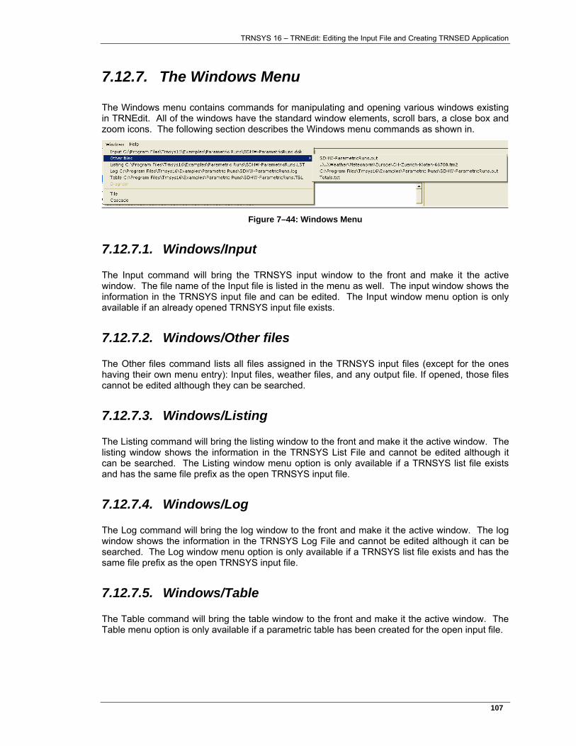
TRNSYS 16 – TRNEdit: Editing the Input File and Creating TRNSED Application
107�
7.12.7. The Windows Menu
The Windows menu contains commands for manipulating and opening various windows existing in TRNEdit. All of the windows have the standard window elements, scroll bars, a close box and zoom icons. The following section describes the Windows menu commands as shown in.
Figure 7–44: Windows Menu
7.12.7.1. Windows/Input
The Input command will bring the TRNSYS input window to the front and make it the active window. The file name of the Input file is listed in the menu as well. The input window shows the information in the TRNSYS input file and can be edited. The Input window menu option is only available if an already opened TRNSYS input file exists.
7.12.7.2. Windows/Other files
The Other files command lists all files assigned in the TRNSYS input files (except for the ones having their own menu entry): Input files, weather files, and any output file. If opened, those files cannot be edited although they can be searched.
7.12.7.3. Windows/Listing
The Listing command will bring the listing window to the front and make it the active window. The listing window shows the information in the TRNSYS List File and cannot be edited although it can be searched. The Listing window menu option is only available if a TRNSYS list file exists and has the same file prefix as the open TRNSYS input file.
7.12.7.4. Windows/Log
The Log command will bring the log window to the front and make it the active window. The log window shows the information in the TRNSYS Log File and cannot be edited although it can be searched. The Log window menu option is only available if a TRNSYS list file exists and has the same file prefix as the open TRNSYS input file.
7.12.7.5. Windows/Table
The Table command will bring the table window to the front and make it the active window. The Table menu option is only available if a parametric table has been created for the open input file.
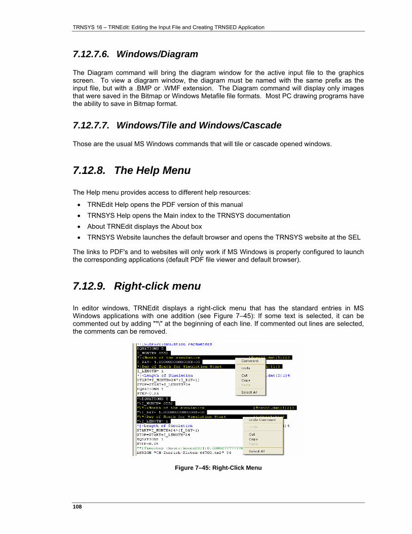
TRNSYS 16 – TRNEdit: Editing the Input File and Creating TRNSED Application
108�
7.12.7.6. Windows/Diagram
The Diagram command will bring the diagram window for the active input file to the graphics screen. To view a diagram window, the diagram must be named with the same prefix as the input file, but with a .BMP or .WMF extension. The Diagram command will display only images that were saved in the Bitmap or Windows Metafile file formats. Most PC drawing programs have the ability to save in Bitmap format.
7.12.7.7. Windows/Tile and Windows/Cascade
Those are the usual MS Windows commands that will tile or cascade opened windows.
7.12.8. The Help Menu
The Help menu provides access to different help resources:
• TRNEdit Help opens the PDF version of this manual • TRNSYS Help opens the Main index to the TRNSYS documentation • About TRNEdit displays the About box • TRNSYS Website launches the default browser and opens the TRNSYS website at the SEL
The links to PDF's and to websites will only work if MS Windows is properly configured to launch the corresponding applications (default PDF file viewer and default browser).
7.12.9. Right-click menu
In editor windows, TRNEdit displays a right-click menu that has the standard entries in MS Windows applications with one addition (see Figure 7–45): If some text is selected, it can be commented out by adding "*\" at the beginning of each line. If commented out lines are selected, the comments can be removed.
Figure 7–45: Right-Click Menu

TRNSYS 16 – TRNEdit: Editing the Input File and Creating TRNSED Application
109�
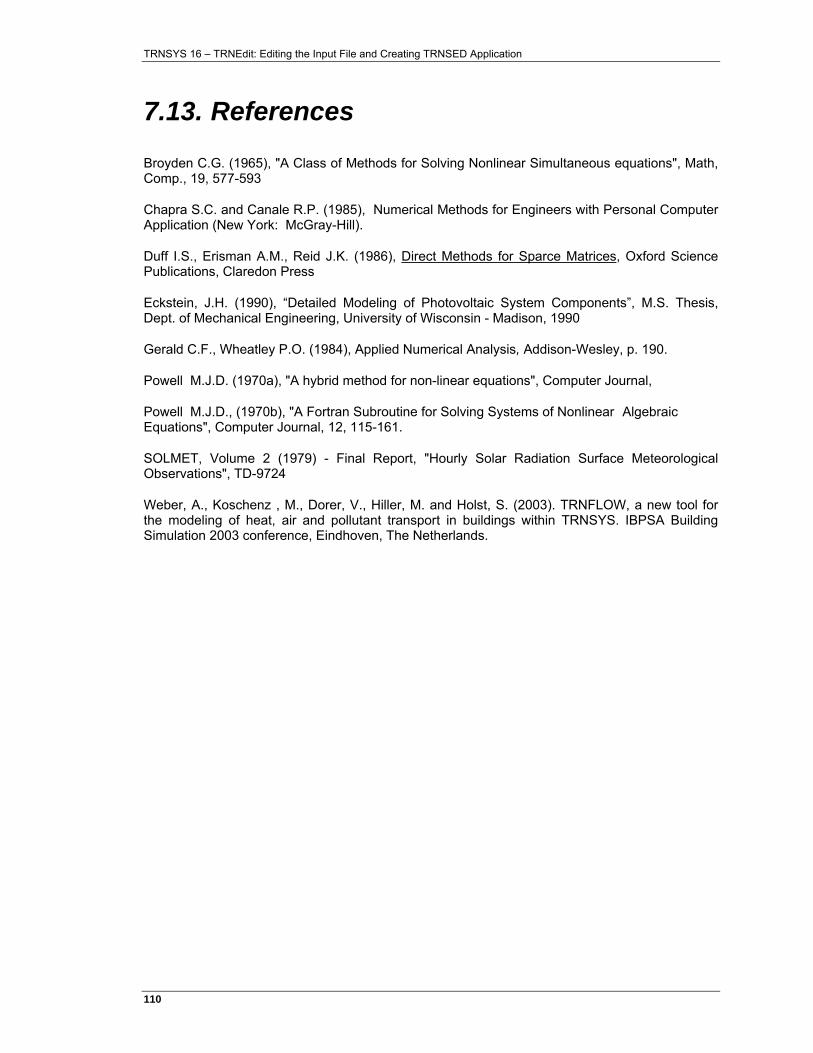
TRNSYS 16 – TRNEdit: Editing the Input File and Creating TRNSED Application
110�
7.13. References
Broyden C.G. (1965), "A Class of Methods for Solving Nonlinear Simultaneous equations", Math, Comp., 19, 577-593
Chapra S.C. and Canale R.P. (1985), Numerical Methods for Engineers with Personal Computer Application (New York: McGray-Hill).
Duff I.S., Erisman A.M., Reid J.K. (1986), Direct Methods for Sparce Matrices, Oxford Science Publications, Claredon Press
Eckstein, J.H. (1990), “Detailed Modeling of Photovoltaic System Components”, M.S. Thesis, Dept. of Mechanical Engineering, University of Wisconsin - Madison, 1990
Gerald C.F., Wheatley P.O. (1984), Applied Numerical Analysis, Addison-Wesley, p. 190.
Powell M.J.D. (1970a), "A hybrid method for non-linear equations", Computer Journal,
Powell M.J.D., (1970b), "A Fortran Subroutine for Solving Systems of Nonlinear Algebraic Equations", Computer Journal, 12, 115-161.
SOLMET, Volume 2 (1979) - Final Report, "Hourly Solar Radiation Surface Meteorological Observations", TD-9724
Weber, A., Koschenz , M., Dorer, V., Hiller, M. and Holst, S. (2003). TRNFLOW, a new tool for the modeling of heat, air and pollutant transport in buildings within TRNSYS. IBPSA Building Simulation 2003 conference, Eindhoven, The Netherlands.