TRM€¦ · TEBT0782 TRM Revision v.45 Exported on 2019-10-18 TEBT0782 TRM Revision: v.45 ... Table...
25
Online version of this document: https://wiki.trenz-electronic.de/display/PD/TEBT0782+TRM TEBT0782 TRM Revision v.45 Exported on 2019-10-18
Transcript of TRM€¦ · TEBT0782 TRM Revision v.45 Exported on 2019-10-18 TEBT0782 TRM Revision: v.45 ... Table...
Online version of this document:
https://wiki.trenz-electronic.de/display/PD/TEBT0782+TRM
TEBT0782 TRM
Revision v.45
Exported on 2019-10-18

TEBT0782 TRM Revision: v.45
Copyright © 2019 Trenz Electronic GmbH 2 of 25 http://www.trenz-electronic.de
1 Table of Contents
1 Table of Contents................................................................................................................................................... 2
2 Table of Figures...................................................................................................................................................... 4
3 Table of Tables ....................................................................................................................................................... 5
4 Overview................................................................................................................................................................. 6
4.1 Key Features........................................................................................................................................................... 6
4.2 Block Diagram ........................................................................................................................................................ 6
4.3 Main Components .................................................................................................................................................. 7
4.4 Initial Delivery State............................................................................................................................................... 8
4.5 Configuration Signals ............................................................................................................................................ 8
5 Signals, Interfaces and Pins................................................................................................................................... 9
5.1 Board to Board (B2B) I/Os ..................................................................................................................................... 9
5.2 XMOD Pin Header ................................................................................................................................................. 10
5.2.1 JTAG/UART to Module SoC/FPGA........................................................................................................................ 10
5.2.2 JTAG/ GPIO to Module CPLD................................................................................................................................ 11
5.3 RJ45 Connectors .................................................................................................................................................. 12
5.4 USB A Stacked Socket.......................................................................................................................................... 12
5.5 SMA Coaxial ......................................................................................................................................................... 13
5.6 Test Points............................................................................................................................................................ 13
6 On-board Peripherals .......................................................................................................................................... 15
6.1 DIP Switch............................................................................................................................................................. 15
7 Power and Power-On Sequence.......................................................................................................................... 16
7.1 Power Supply ....................................................................................................................................................... 16
7.2 Power Consumption ............................................................................................................................................ 16
7.3 Power Distribution Dependencies ...................................................................................................................... 16
7.4 Power-On Sequence ............................................................................................................................................ 17
7.5 Power Rails ........................................................................................................................................................... 17
8 Board to Board Connectors ................................................................................................................................. 18
8.1 Connector Mating height ..................................................................................................................................... 18
8.2 Connector Speed Ratings .................................................................................................................................... 18
8.3 Current Rating ...................................................................................................................................................... 19
8.4 Connector Mechanical Ratings............................................................................................................................ 19
9 Technical Specifications...................................................................................................................................... 20
9.1 Absolute Maximum Ratings ................................................................................................................................. 20
9.2 Recommended Operating Conditions ................................................................................................................ 20
9.3 Physical Dimensions ............................................................................................................................................ 20

TEBT0782 TRM Revision: v.45
Copyright © 2019 Trenz Electronic GmbH 3 of 25 http://www.trenz-electronic.de
10 Currently Offered Variants .................................................................................................................................. 22
11 Revision History ................................................................................................................................................... 23
11.1 Hardware Revision History .................................................................................................................................. 23
11.2 Document Change History................................................................................................................................... 23
12 Disclaimer............................................................................................................................................................. 24
12.1 Data Privacy.......................................................................................................................................................... 24
12.2 Document Warranty............................................................................................................................................. 24
12.3 Limitation of Liability........................................................................................................................................... 24
12.4 Copyright Notice .................................................................................................................................................. 24
12.5 Technology Licenses............................................................................................................................................ 24
12.6 Environmental Protection ................................................................................................................................... 24
12.7 REACH, RoHS and WEEE ...................................................................................................................................... 24

TEBT0782 TRM Revision: v.45
Copyright © 2019 Trenz Electronic GmbH 4 of 25 http://www.trenz-electronic.de
2 Table of FiguresFigure 1: TEBT0782 block diagram.....................................................................................................................................6
Figure 2: TEBT0782 main components ..............................................................................................................................7
Figure 3: Power Distribution .............................................................................................................................................16
Figure 4: Power Sequency.................................................................................................................................................17
Figure 5: Physical Dimension............................................................................................................................................21
Figure 6: Board hardware revision number. ....................................................................................................................23

TEBT0782 TRM Revision: v.45
Copyright © 2019 Trenz Electronic GmbH 5 of 25 http://www.trenz-electronic.de
3 Table of TablesTable 1: Initial delivery state of programmable devices on the module........................................................................ 8
Table 2: Reset process. ..................................................................................................................................................... 8
Table 3: General I/O to B2B connectors information ...................................................................................................... 9
Table 4: JTAG pins connection ....................................................................................................................................... 10
Table 5: CPLD JTAG pins connection ............................................................................................................................. 11
Table 6: XMOD DIP Switch Setting.................................................................................................................................. 11
Table 7: RJ45s Connections to B2B Connectors............................................................................................................ 12
Table 8: Dual Port USB Connections .............................................................................................................................. 13
Table 9: SMAs Connections............................................................................................................................................. 13
Table 10: Test Points Information .................................................................................................................................... 13
Table 11: On board peripherals........................................................................................................................................ 15
Table 12: DIP Switch Connections.................................................................................................................................... 15
Table 13: Power Consumption ......................................................................................................................................... 16
Table 14: Module power rails............................................................................................................................................ 17
Table 15: Connector specifications. ................................................................................................................................. 18
Table 16: Connectors. ....................................................................................................................................................... 18
Table 17: Speed rating. ..................................................................................................................................................... 18
Table 18: PS absolute maximum ratings ......................................................................................................................... 20
Table 19: Recommended operating conditions. ............................................................................................................. 20
Table 20: Trenz Electronic Shop Overview ...................................................................................................................... 22
Table 21: Hardware Revision History ............................................................................................................................... 23
Table 22: Document change history. ............................................................................................................................... 23

TEBT0782 TRM Revision: v.45
Copyright © 2019 Trenz Electronic GmbH 6 of 25 http://www.trenz-electronic.de
••••••••••
4 OverviewThe Trenz Electronic TEBT0782 is a carrier for TE0782, TE0783 and TE0784 module.
Refer to http://trenz.org/tebt0782-info for the current online version of this manual and other available documentation.
4.1 Key Features3 x Samtec ASP-122953-01 160-pin stackable, compatible with TE078x2 mm MC LB2-A Soldered Connector for power supply (12V input)4 SMA connectors for MGT2 x 12 pin headers for XMOD1 x DIP switch for modules CPLD Access2 x RJ45 ConnectorUSB A Stacked Connector Equipped with two TE0790 XMOD FTDI JTAG adaptersVoltage regulatorsDimension: 115 x 115 mm
4.2 Block Diagram
Figure 1: TEBT0782 block diagram
TEBT0782 TRM Revision: v.45
Copyright © 2019 Trenz Electronic GmbH 7 of 25 http://www.trenz-electronic.de
1.2.3.4.5.6.7.8.9.
10.11.12.
4.3 Main Components
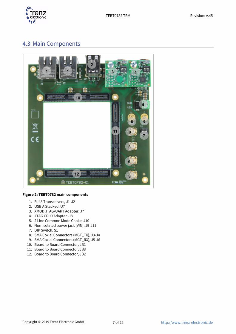
Figure 2: TEBT0782 main components
RJ45 Transceivers, J1-J2USB A Stacked, U7XMOD JTAG/UART Adapter, J7JTAG CPLD Adapter -J82 Line Common Mode Choke, J10Non-isolated power jack (VIN), J9-J11DIP Switch, S1SMA Coxial Connectors (MGT_TX), J3-J4SMA Coxial Connectors (MGT_RX), J5-J6Board to Board Connector, JB1Board to Board Connector, JB3Board to Board Connector, JB2
TEBT0782 TRM Revision: v.45
Copyright © 2019 Trenz Electronic GmbH 8 of 25 http://www.trenz-electronic.de
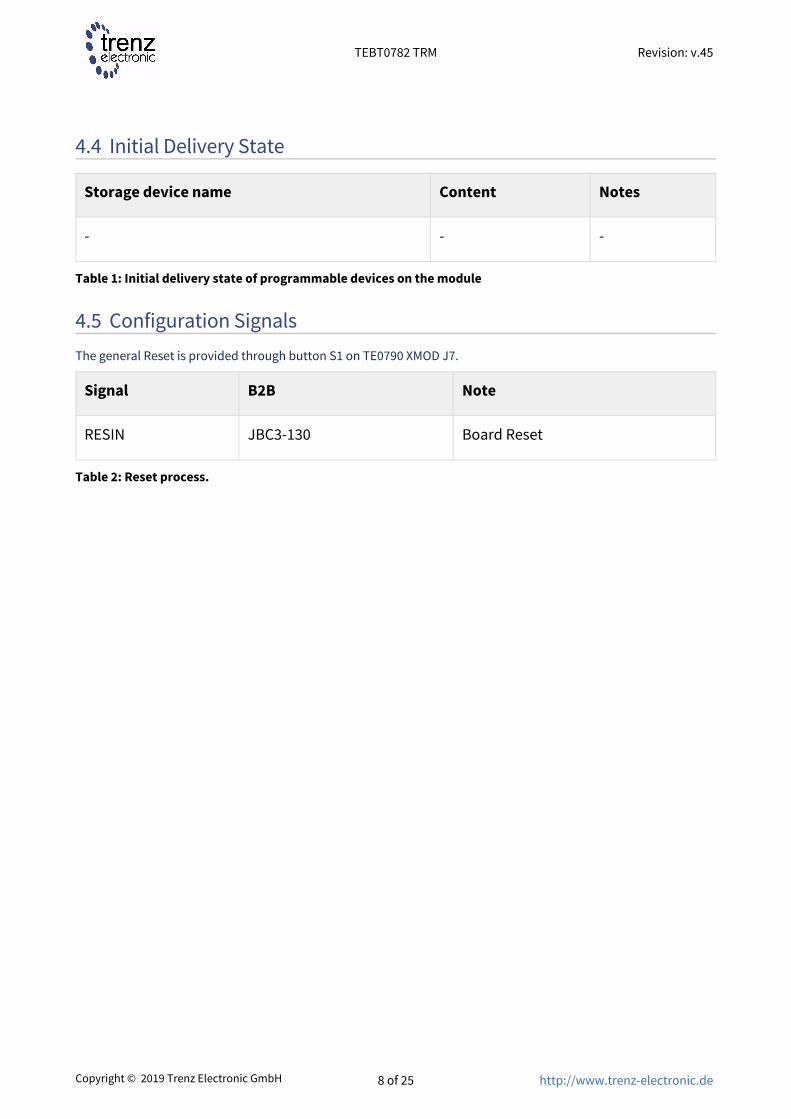
4.4 Initial Delivery State
Storage device name Content Notes
- - -
Table 1: Initial delivery state of programmable devices on the module
4.5 Configuration SignalsThe general Reset is provided through button S1 on TE0790 XMOD J7.
Signal B2B Note
RESIN JBC3-130 Board Reset
Table 2: Reset process.

TEBT0782 TRM Revision: v.45
Copyright © 2019 Trenz Electronic GmbH 9 of 25 http://www.trenz-electronic.de
5 Signals, Interfaces and Pins
5.1 Board to Board (B2B) I/OsFPGA bank number and number of I/O signals connected to the B2B connector:
B2B Connector
Interface Number of I/O Notes
JB1 RJ45, J1B-J1C 1 Differential pair, 2 Single Ended
Yellow, Green LEDs
RJ45, J1A 4 Differential pair, 8 Single Ended
PHY1 MDIO
RJ45, J2B-J2C 1 Differential pair, 2 Single Ended
Yellow, Green LEDs
RJ45, J2A 4 Differential pair, 8 Single Ended
PHY2 MDIO
TE0790 Base, J8 4 Single Ended
TE0790 Base, J7 1 Single Ended
USB A Stacked, U7 2 Single Ended USB
Power Switch, U1 2 Single Ended
SMD Line Filter, L6 1 Differential pair, 2 Single Ended
USB1_D
SMD Line Filter, L7 1 Differential pair, 2 Single Ended
USB2_D
ESD protection diode, U5
1 Single Ended USB1_VBUS
ESD protection diode, U8
1 Single Ended USB2_VBUS
JB2 Module TE078x FPGA, Bank 111-112
16 Differential pair, 32 Single Ended
MGT_RX8...15, MGT_TX8...15
Module TE078x FPGA, Bank 34
1 Differential pair, 2 Single Ended
J1_B34_VRP, J1_B34_VRN

TEBT0782 TRM Revision: v.45
Copyright © 2019 Trenz Electronic GmbH 10 of 25 http://www.trenz-electronic.de
B2B Connector
Interface Number of I/O Notes
Module TE078x FPGA, Bank 34
1 Differential pair, 2 Single Ended
J1_B33_VRP, J1_B33_VRN
JB3 TE0790 Base, J8 4 Single Ended M_TCK, M_TMS, M_TDO, M_TDI
TE0790 Base, J7 4 Single Ended
2 Single Ended
1 Single Ended
TCK, TMS, TDO, TDI
UART RX/TX
RESIN
DIP Switch, S1-A 1 Single Ended JTAGENB
SMA Coaxial, J3...6 2 Differential pair, 4 Single Ended
MGT_RX0, MGT_TX0
Module TE0782...4 FPGA, Bank 109-110
16 Differential pair, 32 Single Ended
MGT_RX1...7, MGT_TX0...7
Table 3: General I/O to B2B connectors information
5.2 XMOD Pin Header
5.2.1 JTAG/UART to Module SoC/FPGA
JTAG access to the TE078x SoM is available through B2B connector JB3. JTAG access is provided by TE0790 XMOD Adapter on Pin Header J7.
JTAG Interface Pins Signal Name B2B Connector Notes
A XMOD_A JB3C-129 UART
B XMOD_B JB3C-135 UART
C TCK JB3C-141 JTAG
D TDO JB3C-148 JTAG
E CPLD_GPIO4 JB1A-18
F TDI JB3C-147 JTAG
G RESIN JB3C-130 General Reset

TEBT0782 TRM Revision: v.45
Copyright © 2019 Trenz Electronic GmbH 11 of 25 http://www.trenz-electronic.de
JTAG Interface Pins Signal Name B2B Connector Notes
H TMS JB3C-142 JTAG
3.3V 3.3V_M JB1- JB3
VIO 3.3V_M JB1- JB3 3.3V
Table 4: JTAG pins connection
5.2.2 JTAG/ GPIO to Module CPLD
JTAG access to the System Controller CPLD is provided through B2B connector J3. JTAG access to CPLD is provided by TE0790 XMOD Adapter on Pin Header J8.
Pin 'JTAGENB' must be set high, using DIP Switch S1-A in order to program the System Controller CPLD via JTAG interaface.
JTAG Interface Pins Signal Name B2B Connector Notes
A CPLD_GPIO0 JB1A-10
B CPLD_GPIO1 JB1A-12
C M_TCK JB3B-81
D M_TDO JB3B-88
E CPLD_GPIO2 JB1A-14
F M_TDI JB3B-87
G CPLD_GPIO3 JB1A-16
H M_TMS JB3B-82
3.3V 3.3V_CPLD JB1- JB3
VIO 3.3V_CPLD JB1- JB3 3.3V
Table 5: CPLD JTAG pins connectionDIP Switch S2 on TE0790 must be set and fixed like the following table.
DIP Switch Setting Notes
S2-1 ON JTAGENB (Enable/Disable module JTAG CPLD IOs)
S2-2 OFF NC

TEBT0782 TRM Revision: v.45
Copyright © 2019 Trenz Electronic GmbH 12 of 25 http://www.trenz-electronic.de
DIP Switch Setting Notes
S2-3 OFF NC
S2-4 OFF NC
Table 6: XMOD DIP Switch Setting
5.3 RJ45 Connectors
Signal Name RJ45-J1 Pin RJ45-J2 Pin Notes
B2B
PHY_MDI0_P JB1A-23 JB1A-39
PHY_MDI0_N JB1A-21 JB1A-37
PHY_MDI1_P JB1A-19 JB1A-35
PHY_MDI1_N JB1A-17 JB1A-33
PHY_MDI2_P JB1A-15 JB1A-31
PHY_MDI2_N JB1A-13 JB1A-29
PHY_MDI3_P JB1A-11 JB1A-27
PHY_MDI3_N JB1A-9 JB1A-25
J2_TX9_P JB1A-95 - LED Green/Yellow
J2_TX9_N JB1A-97 - LED Green/Yellow
J2_RX9_N - JB1A-96 LED Green/Yellow
J2_RX9_P - JB1A-98 LED Green/Yellow
Table 7: RJ45s Connections to B2B Connectors
5.4 USB A Stacked SocketThe USB A Stacked (U7) is a dual port USB Socket which provides two USB ports.

TEBT0782 TRM Revision: v.45
Copyright © 2019 Trenz Electronic GmbH 13 of 25 http://www.trenz-electronic.de
Signal Name
Port A Port B Notes
B2B Connected to
B2B Connected to
USB_D_P JB1A-28
SMD Line Filter, L7
JB1A-40 SMD Line Filter, L6
USB_D_N JB1A-26
SMD Line Filter, L7
JB1A-38 SMD Line Filter, L6
USB_VBUS JB1A-24
SMD Line Filter, L7
JB1A-36 SMD Line Filter, L6
VBUS_V_EN
JB1A-30
Power Switch, U1
JB1A-32 Power Switch, U1
Table 8: Dual Port USB Connections
5.5 SMA Coaxial The TEBT0782 carrier is equipped with 4x SMA Coaxial straight connectors.
Designator Schematic B2B Notes
J3 MGT_TX0_N JB3A-29 Transfer
J4 MGT_TX0_P JB3A-31 Transfer
J5 MGT_RX0_N JB3A-30 Receive
J6 MGT_RX0_P JB3A-32 Receive
Table 9: SMAs Connections
5.6 Test Points
Test Point Signals B2B Connector Notes
TP 1 VBAT_I JB3-124
TP 2 OTG2_ID JB1-22
TP 3 OTG1_ID JB1-34
TP 4 USB1_VBUS JB1-36

TEBT0782 TRM Revision: v.45
Copyright © 2019 Trenz Electronic GmbH 14 of 25 http://www.trenz-electronic.de
Test Point Signals B2B Connector Notes
TP 5 USB2_VBUS JB1-24
TP 6 M_TCK JB3-81
TP 7 M_TDO JB3-88
TP 8 M_TDI JB3-87
TP 9 M_TMS JB3-82
TP 10 TCK JB3-141
TP 11 TDO JB3-148
TP 12 TDI JB3-147
TP 13 TMS JB3-142
TP 14 VIN JB1-165...168
TP 15 5V -
TP 16 3.3V_CPLD JB1-147...148
TP 17-18 GND -
Table 10: Test Points Information

TEBT0782 TRM Revision: v.45
Copyright © 2019 Trenz Electronic GmbH 15 of 25 http://www.trenz-electronic.de
6 On-board Peripherals
Chip/Interface Designator Notes
DIP Switch(see page 15) S1
Table 11: On board peripherals
6.1 DIP Switch
Switch Connected to B2B Notes
S1-A JTABENB JB3C-136
S1-B...D - - Not connected
Table 12: DIP Switch Connections

TEBT0782 TRM Revision: v.45
Copyright © 2019 Trenz Electronic GmbH 16 of 25 http://www.trenz-electronic.de
7 Power and Power-On Sequence
7.1 Power SupplyPower supply with minimum current capability of 3A for system startup is recommended.
7.2 Power Consumption
Power Input Pin Typical Current
VIN TBD*
Table 13: Power Consumption* TBD - To Be Determined
7.3 Power Distribution Dependencies12V power supply (VIN) on J9/J11 (2 mm MC LB2-A solder-in) or on J10 (TE1.5/2-3.5H).
Figure 3: Power Distribution
TEBT0782 TRM Revision: v.45
Copyright © 2019 Trenz Electronic GmbH 17 of 25 http://www.trenz-electronic.de
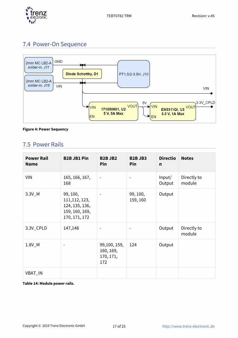
7.4 Power-On Sequence
Figure 4: Power Sequency
7.5 Power Rails
Power Rail Name
B2B JB1 Pin B2B JB2 Pin
B2B JB3 Pin
Direction
Notes
VIN 165, 166, 167, 168
- - Input/Output
Directly to module
3.3V_M 99, 100, 111,112, 123, 124, 135, 136, 159, 160, 169, 170, 171, 172
- 99, 100, 159, 160
Output
3.3V_CPLD 147,148 - - Output Directly to module
1.8V_M - 99,100, 159, 160, 169, 170, 171, 172
124 Output
VBAT_IN
Table 14: Module power rails.

TEBT0782 TRM Revision: v.45
Copyright © 2019 Trenz Electronic GmbH 18 of 25 http://www.trenz-electronic.de
•
8 Board to Board Connectors
8.5 x 8.5 SoMs have three Samtec Q Strip Socket on the bottom side.
3 x QSH–090–01–F–D-A (compatible to QTH–090–01–L–D–A ), (180 pins, "60" per bank)
Connector Specifications Value
Insulator material Black Liquid Crystal Polymer
Stacking height 5 mm
Contact material Phosphor-bronze
Plating Au or Sn over 50 µ" (1.27 µm) Ni
Current rating 2 A per pin (2 pins powered)
Operating temperature range -55 °C to +125 °C
RoHS compliant Yes
Table 15: Connector specifications.
8.1 Connector Mating heightWhen using the same type on baseboard, the mating height is 5mm. Other mating heights are possible by using connectors with a different height
Order number Connector on baseboard compatible to Mating height
ASP-122953-01 QTH–090–01–L–D–A 5 mm
ASP-122952-01 QSH–090–01–F–D-A 5 mm
Table 16: Connectors.The module can be manufactured using other connectors upon request.
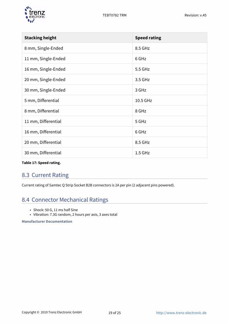
8.2 Connector Speed RatingsThe Q Strip connector speed rating depends on the stacking height; please see the following table:
Stacking height Speed rating
5 mm, Single-Ended 9.5 GHz
TEBT0782 TRM Revision: v.45
Copyright © 2019 Trenz Electronic GmbH 19 of 25 http://www.trenz-electronic.de
••
Stacking height Speed rating
8 mm, Single-Ended 8.5 GHz
11 mm, Single-Ended 6 GHz
16 mm, Single-Ended 5.5 GHz
20 mm, Single-Ended 3.5 GHz
30 mm, Single-Ended 3 GHz
5 mm, Differential 10.5 GHz
8 mm, Differential 8 GHz
11 mm, Differential 5 GHz
16 mm, Differential 6 GHz
20 mm, Differential 8.5 GHz
30 mm, Differential 1.5 GHz
Table 17: Speed rating.
8.3 Current RatingCurrent rating of Samtec Q Strip Socket B2B connectors is 2A per pin (2 adjacent pins powered).
8.4 Connector Mechanical RatingsShock: 50 G, 11 ms half SineVibration: 7.3G random, 2 hours per axis, 3 axes total
Manufacturer Documentation
TEBT0782 TRM Revision: v.45
Copyright © 2019 Trenz Electronic GmbH 20 of 25 http://www.trenz-electronic.de
••
9 Technical Specifications
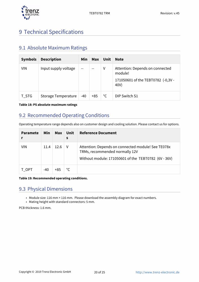
9.1 Absolute Maximum Ratings
Symbols Description Min Max Unit Note
VIN Input supply voltage -- -- V Attention: Depends on connected module!
171050601 of the TEBT0782 (-0,3V - 40V)
T_STG Storage Temperature -40 +85 °C DIP Switch S1
Table 18: PS absolute maximum ratings
9.2 Recommended Operating ConditionsOperating temperature range depends also on customer design and cooling solution. Please contact us for options.
Parameter
Min Max Units
Reference Document
VIN 11.4 12.6 V Attention: Depends on connected module! See TE078x TRMs, recommended normally 12V
Without module: 171050601 of the TEBT0782 (6V - 36V)
T_OPT -40 +85 °C
Table 19: Recommended operating conditions.
9.3 Physical DimensionsModule size: 116 mm × 116 mm. Please download the assembly diagram for exact numbers.Mating height with standard connectors: 5 mm.
PCB thickness: 1.6 mm.

TEBT0782 TRM Revision: v.45
Copyright © 2019 Trenz Electronic GmbH 21 of 25 http://www.trenz-electronic.de
Figure 5: Physical Dimension

TEBT0782 TRM Revision: v.45
Copyright © 2019 Trenz Electronic GmbH 22 of 25 http://www.trenz-electronic.de
1 https://shop.trenz-electronic.de/en/search?sSearch=TEBT07822 https://shop.trenz-electronic.de/de/search?sSearch=TEBT0782
10 Currently Offered Variants
Trenz shop TEBT0728 overview page
English page1 German page2
Table 20: Trenz Electronic Shop Overview
TEBT0782 TRM Revision: v.45
Copyright © 2019 Trenz Electronic GmbH 23 of 25 http://www.trenz-electronic.de
3 https://shop.trenz-electronic.de/Download/?path=Trenz_Electronic/Modules_and_Module_Carriers/8.5x8.5/8.5x8.5_Carriers/TEBT0782/REV01
4 https://wiki.trenz-electronic.de/display/~j.hartfiel5 https://wiki.trenz-electronic.de/display/~P.Babakhani6 https://wiki.trenz-electronic.de/display/~j.hartfiel
••
•
•
11 Revision History
11.1 Hardware Revision History
Date Revision Changes Documentation Link
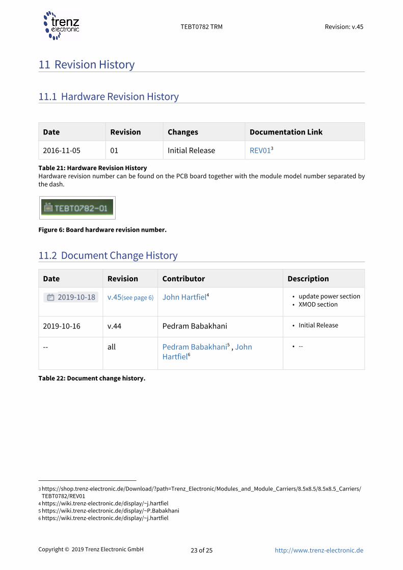
2016-11-05 01 Initial Release REV013
Table 21: Hardware Revision HistoryHardware revision number can be found on the PCB board together with the module model number separated by the dash.
Figure 6: Board hardware revision number.
11.2 Document Change History
Date Revision Contributor Description
2019-10-18 v.45(see page 6) John Hartfiel4 update power sectionXMOD section
2019-10-16 v.44 Pedram Babakhani Initial Release
-- all Pedram Babakhani5 , John Hartfiel6
--
Table 22: Document change history.

TEBT0782 TRM Revision: v.45
Copyright © 2019 Trenz Electronic GmbH 24 of 25 http://www.trenz-electronic.de
12 Disclaimer
12.1 Data PrivacyPlease also note our data protection declaration at https://www.trenz-electronic.de/en/Data-protection-Privacy
12.2 Document WarrantyThe material contained in this document is provided “as is” and is subject to being changed at any time without notice. Trenz Electronic does not warrant the accuracy and completeness of the materials in this document. Further, to the maximum extent permitted by applicable law, Trenz Electronic disclaims all warranties, either express or implied, with regard to this document and any information contained herein, including but not limited to the implied warranties of merchantability, fitness for a particular purpose or non infringement of intellectual property. Trenz Electronic shall not be liable for errors or for incidental or consequential damages in connection with the furnishing, use, or performance of this document or of any information contained herein.
12.3 Limitation of LiabilityIn no event will Trenz Electronic, its suppliers, or other third parties mentioned in this document be liable for any damages whatsoever (including, without limitation, those resulting from lost profits, lost data or business interruption) arising out of the use, inability to use, or the results of use of this document, any documents linked to this document, or the materials or information contained at any or all such documents. If your use of the materials or information from this document results in the need for servicing, repair or correction of equipment or data, you assume all costs thereof.
12.4 Copyright NoticeNo part of this manual may be reproduced in any form or by any means (including electronic storage and retrieval or translation into a foreign language) without prior agreement and written consent from Trenz Electronic.
12.5 Technology LicensesThe hardware / firmware / software described in this document are furnished under a license and may be used /modified / copied only in accordance with the terms of such license.
12.6 Environmental ProtectionTo confront directly with the responsibility toward the environment, the global community and eventually also oneself. Such a resolution should be integral part not only of everybody's life. Also enterprises shall be conscious of their social responsibility and contribute to the preservation of our common living space. That is why Trenz Electronic invests in the protection of our Environment.
12.7 REACH, RoHS and WEEEREACH

TEBT0782 TRM Revision: v.45
Copyright © 2019 Trenz Electronic GmbH 25 of 25 http://www.trenz-electronic.de
7 http://guidance.echa.europa.eu/8 https://echa.europa.eu/candidate-list-table9 http://www.echa.europa.eu/
Trenz Electronic is a manufacturer and a distributor of electronic products. It is therefore a so called downstream user in the sense of REACH7. The products we supply to you are solely non-chemical products (goods). Moreover and under normal and reasonably foreseeable circumstances of application, the goods supplied to you shall not release any substance. For that, Trenz Electronic is obliged to neither register nor to provide safety data sheet. According to present knowledge and to best of our knowledge, no SVHC (Substances of Very High Concern) on the Candidate List8 are contained in our products. Furthermore, we will immediately and unsolicited inform our customers in compliance with REACH - Article 33 if any substance present in our goods (above a concentration of 0,1 % weight by weight) will be classified as SVHC by the European Chemicals Agency (ECHA)9.
RoHS
Trenz Electronic GmbH herewith declares that all its products are developed, manufactured and distributed RoHS compliant.
WEEE
Information for users within the European Union in accordance with Directive 2002/96/EC of the European Parliament and of the Council of 27 January 2003 on waste electrical and electronic equipment (WEEE).
Users of electrical and electronic equipment in private households are required not to dispose of waste electrical and electronic equipment as unsorted municipal waste and to collect such waste electrical and electronic equipment separately. By the 13 August 2005, Member States shall have ensured that systems are set up allowing final holders and distributors to return waste electrical and electronic equipment at least free of charge. Member States shall ensure the availability and accessibility of the necessary collection facilities. Separate collection is the precondition to ensure specific treatment and recycling of waste electrical and electronic equipment and is necessary to achieve the chosen level of protection of human health and the environment in the European Union. Consumers have to actively contribute to the success of such collection and the return of waste electrical and electronic equipment. Presence of hazardous substances in electrical and electronic equipment results in potential effects on the environment and human health. The symbol consisting of the crossed-out wheeled bin indicates separate collection for waste electrical and electronic equipment.
Trenz Electronic is registered under WEEE-Reg.-Nr. DE97922676.
2019-06-07