
TRIWEB RETAINED SOIL WALL SYSTEM - Tricon Precast, Ltd. · TRIWEB RETAINED SOIL WALL SYSTEM The...
7
T r i c o n P r ec a s T l T d . TRIWEB™ RETAINED SOIL WALL SYSTEM (5’-0” x 5’-0” Panels) CONSTRUCTION MANUAL WWW.TRICONPRECAST.COM Rev. October 2012 PLEASE CONTACT YOUR LOCAL SYSTEM PROVIDER:
Transcript of TRIWEB RETAINED SOIL WALL SYSTEM - Tricon Precast, Ltd. · TRIWEB RETAINED SOIL WALL SYSTEM The...
T r i c o n P r e c a s T l T d .
TRIWEB™RETAINED SOILWALL SYSTEM(5’-0” x 5’-0” Panels)
CONSTRUCTION MANUAL
WWW.TRICONPRECAST.COM
Rev. October 2012
PLEASE CONTACT YOUR LOCAL SYSTEM PROVIDER:

NOTES
______________________________________________________________________________________________________________________________________________________________________________________________________________________________________________________________________________________________________________________________________________________________________________________________________________________________________________________________________________________________________________________________________________________________________________________________________________________________________________________________________________________________________________________________________________________________________________________________________________________________________________________________________________________________________________________________________________________________________________________________________________________________________________________________________________________________________________________________________________________________________________________________________________________________________________________________________________________________________________________________________________________________________________________________________________________________________________________________________________________________________________________________________________________________________________________________________________________________________________________________________________________________________________________________________________________________________________________________________________________________________________________________________________________________________________________________________________________________________________________________________________________________________________________________________________________________________________________________________________________
1
TRIWEBTRIWEB RETAINEDRETAINED SOILSOIL
WALL SYSTEMWALL SYSTEMThe TriwebTM Wall is a mechanically stabilized earth retaining wall structurecomprised of a cast-in-place leveling course (by others), precast concrete fasciapanels, panel alignment shims, HDPE bearing pads, filter fabric, adhesive jointmaterials, connection anchors, ParaWeb geosynthetic strips soil reinforcementcombined with a select backfill mass (by others). Included with the system areengineered design and erection drawings, precast concrete copings, as well aslimited on-site technical assistance as required.
Figure 1 below illustrates the installed system.
FIGURE 1
TMTM

ounded in 1987, Tricon Precast Ltd. provides innovative engineered MSE wall and bridgesystems throughout North America. With headquarters in Houston, Tricon operates twostate-of-the-art plants strategically located in Texas; Houston in the Gulf Coast Region and
San Antonio in the Central Texas Region making it the largest precast concrete manufacturer in thestate. Networks of licensed producer partners expand the reach of the Tricon systems by providingmanufacturing and support across the US and Canada.
Tricon de Mexico, headquartered in Mexico City, provides the Tricon products and systems intomany parts of that country.
TEG Engineering, headquartered in Grand Rapids, MI, with offices in Texas, provides a full range ofstructural engineering services not only for all Tricon system applications but for other civilconstruction projects across the continent. TEG continues to expand its network with the mosttalented and innovative professional engineering staff in the country.
Tricon’s unique patented systems are produced and offered by a growing number of licensedprecast affiliate partners. Licensing agreements are currently available in certain geographiclocations. Interested precast concrete producers should please contact us for more information.
Products and Systems include:
2 11
T r i c o n P r e c a s T l T d .
FIGURE 3
FIGURE 2
F
• Retained Soil Wall System™• Drill Shaft Fascia Panel Wall System• Soil Nail Fascia Panel Wall System• Temporary Wire Wall System• Permanent Wire Wall System• Redi-Span™ Arch Bridge System
• Con-Struct™ Prefabricated Bridge System• Sound Wall System• Privacy Wall System• Precast Concrete Traffic Barriers• Custom Civil, Industrial and Commercial
Precast Concrete Services
10 3
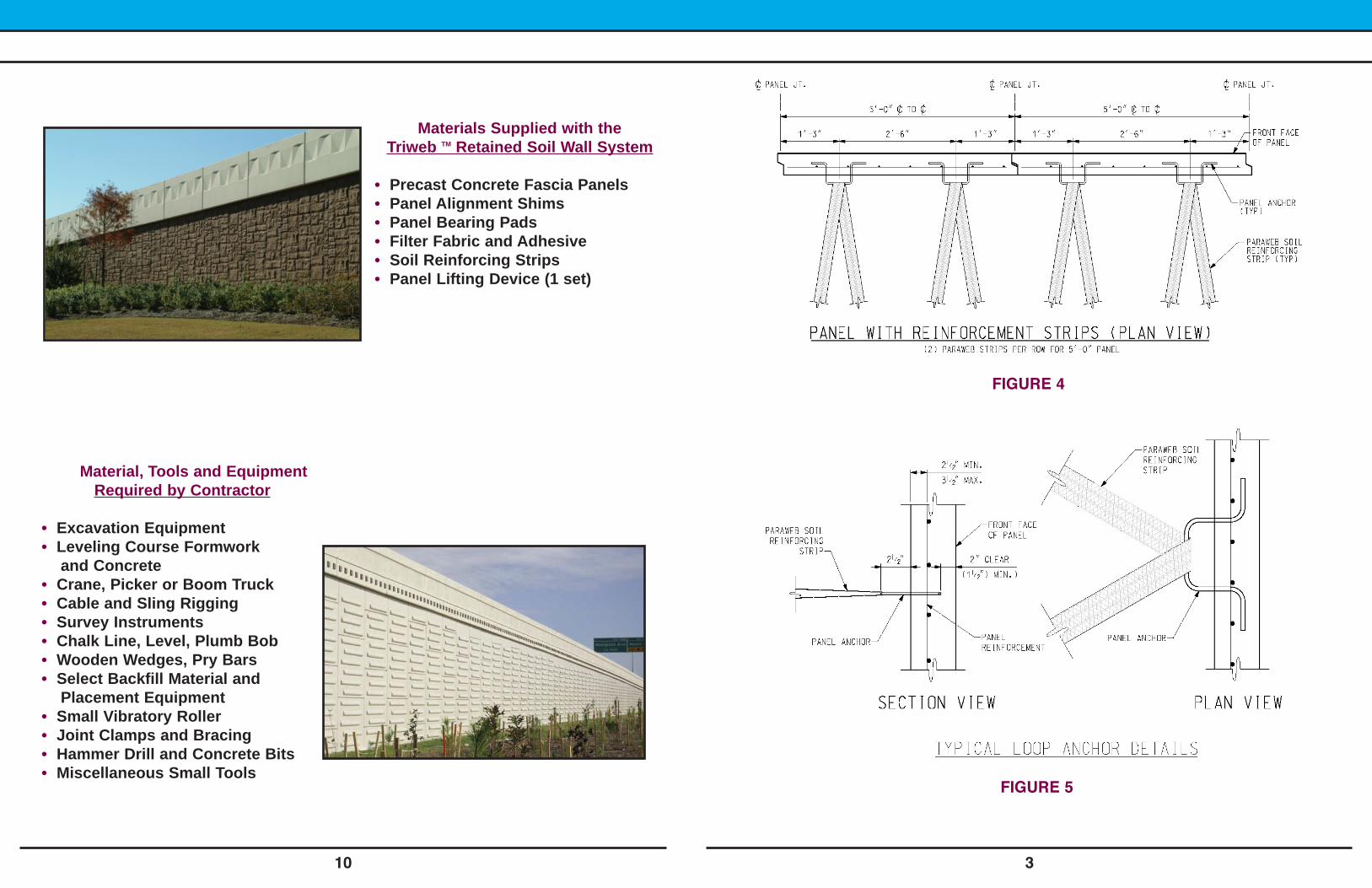
FIGURE 4
FIGURE 5
Material, Tools and Equipment Required by Contractor
• Excavation Equipment• Leveling Course Formworkand Concrete
• Crane, Picker or Boom Truck• Cable and Sling Rigging• Survey Instruments• Chalk Line, Level, Plumb Bob• Wooden Wedges, Pry Bars• Select Backfill Material andPlacement Equipment
• Small Vibratory Roller• Joint Clamps and Bracing• Hammer Drill and Concrete Bits• Miscellaneous Small Tools
Materials Supplied with the Triweb Retained Soil Wall System
• Precast Concrete Fascia Panels• Panel Alignment Shims• Panel Bearing Pads• Filter Fabric and Adhesive• Soil Reinforcing Strips• Panel Lifting Device (1 set)
TM

4 9
V. Final Completion of the Wall
A. Install top panels as described in Step IV – Installation of Second and FollowingCourses.
B. Complete backfill and compaction. Remove all bracing, clamps, and wedges.
C. Form and pour the level-up course for precast coping, or form and pour coping inplace as specified.
FIGURE 6
Delivery, Storage and Handling
Soil Reinforcement Strips
• Strips are supplied in rolls, and tagged with description.• Strips will be transported to site on pallets with a maximum weight of
1.5 tons.• A suitably large area should be set up to hold all items, placing in
groups by grade as shown by color coded labels.
Wall Panels
• Unloading - Panels can be unloaded individually by using a fourpoint lift with strips. Panels should be stacked four high on groundlevel. The panels are shipped stacked four high and can be unloadedby stack using nylon slings.
• Storage - Panels should be stored in adequate dunnage as near tothe final setting position as possible on firm, level ground. Dunnageshould maintain vertical alignment to eliminate the chance of thepanel being damaged. When lifting panels off storage stack, alwaysplace a wooden block between panels to prevent damage whenrotating to vertical position. (See figure 6)
• Care should be taken not to break, bend, or otherwise damage panelanchors.

8 5
IV. Installation of Second and Following Courses
A. Always backfill to the top of the prior course before setting the next course.
B. Remove clamps one panel at a time. Place supplied bearing pads on top of the panelsin the preformed bearing pad pockets.
C. Set intermediate panel in place. Check spacing, and the horizontal and verticalalignment of the panel. Set joint clamps.
D. Install supplied filter fabric in the vertical/horizontal joints with the provided adhesive.
ERECTION PROCEDUREERECTION PROCEDURE
I. Level Pad Construction
A. Layout the leveling pad on the centerline and grade of the wall panels as provided bythe project drawings.
B. Course dimensions are detailed in the supplied erection drawings. Typical pad is 6inches thick and 12 inches wide.
C. Finish leveling course to a smooth trowel finish.
D. LINE AND GRADE MUST BE HELD TO 1/4” TOLERANCE.
E. Install backfill and reinforcementas described in Step III - Backfill.
F. Check vertical alignment, nobracing shall be required for theremainder of the wall.
G. Backfill front of the wall above theleveling pad.
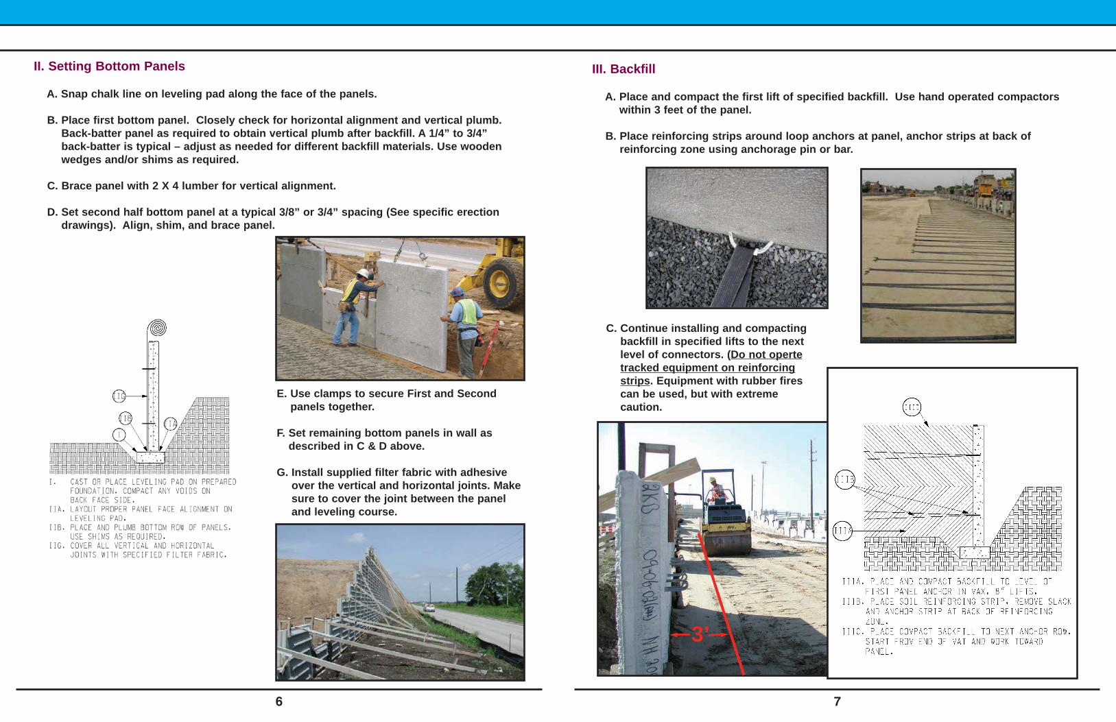
II. Setting Bottom Panels
A. Snap chalk line on leveling pad along the face of the panels.
B. Place first bottom panel. Closely check for horizontal alignment and vertical plumb.Back-batter panel as required to obtain vertical plumb after backfill. A 1/4” to 3/4”back-batter is typical – adjust as needed for different backfill materials. Use woodenwedges and/or shims as required.
C. Brace panel with 2 X 4 lumber for vertical alignment.
D. Set second half bottom panel at a typical 3/8” or 3/4” spacing (See specific erectiondrawings). Align, shim, and brace panel.
6 7
III. Backfill
A. Place and compact the first lift of specified backfill. Use hand operated compactorswithin 3 feet of the panel.
B. Place reinforcing strips around loop anchors at panel, anchor strips at back ofreinforcing zone using anchorage pin or bar.
3’
E. Use clamps to secure First and Secondpanels together.
F. Set remaining bottom panels in wall asdescribed in C & D above.
G. Install supplied filter fabric with adhesiveover the vertical and horizontal joints. Makesure to cover the joint between the paneland leveling course.
C. Continue installing and compactingbackfill in specified lifts to the nextlevel of connectors. (Do not opertetracked equipment on reinforcingstrips. Equipment with rubber firescan be used, but with extremecaution.


![Dynamic Stability of Soil-Reinforced Wallsonlinepubs.trb.org/Onlinepubs/trr/1989/1242/1242-005.pdf · Dynamic Stability of Soil-Reinforced Walls ] ... retained behind the wall as](https://static.fdocuments.in/doc/165x107/5b5b33db7f8b9aa30c8dafc4/dynamic-stability-of-soil-reinforced-dynamic-stability-of-soil-reinforced-walls.jpg)


