Trivial Pursuit Special Edition; PC-21/2 - Windy Urtnowski · and I have used those plans to build...
17
Trivial Pursuit Special Edition; PC-21/2 Peter Germann, July 2008 After spending considerable time building and flying legendary US east coast designs and their various derivates, I thought it would be a good idea to widen my view by looking to the west coast. Not necessarily for the better because what I have found during all of these years was that quite a number of pilots have made very substantial progress once they have reached and mastered what I would like to call the „Cardinal“ level. I do believe that what was created by “Big” Jim Greenaway and Windy Urtnowski compares well to Ted Fancher’s “Trivial Pursuit” which over many years of development has unquestionably become something like an “industry standard” for the c/l stunt community. Even David Fitzgerald’s very successful 2006 Star Gazer is based on the “Special Edition” version of the “Trivial Pursuit”. This version is offered for sale either in kit form or as a set of plans, by RSM in the USA: http://www.rsmdistribution.com and I have used those plans to build my PC-21. Whenever I entered a new field, such as when beginning to fly pipes or 4-cycle engines, I always searched expert help wherever I could find it. I have found the kind of advice and information needed and I owe great thanks to people like Bob Hunt explaining me how to operate the OPS equipped „Saturn“, to Windy leading me up the ST.60 ladder and now to Ted Fancher and David Fitzgerald generously sharing their expert knowledge of the Trivial Pursuit and the PA .75 2-port engine. At this point in time, the Swiss manufacturer Pilatus is delivering its latest aircraft to the Swiss Air Force. The PC-21 is an advanced trainer using its fly-by-wire and full glass cockpit systems to simulate characteristics and behaviour of different aircraft from a basic trainer up to a heavy fighter, such the FA-18 flown by the SAF. As the artist having done the paint scheme for the Air Force happens to be a modeller it was quite easy to get a copy and therefore I decided to build the Trivial Pursuit with a fuselage looking a bit like the Pilatus PC-21 aircraft. The only number I have changed was the hingeline-to-hingeline distance where I have added 37mm (1.45 in). Do not ask me why because while I have never flown a Trivial Pursuit before, I was naive, or stupid, enough to hope I might get a bit more corner from this. Well, I got it but unfortunately a bit too much of it. Following Ted’s recommendation what I did, too, was increasing the flap width by 5mm (0.2“) in order to compensate for the expected weight. This proved to be very wise indeed, because when I found the PC- 21 tipping the scale at 2'030 Grams (71 oz) I was glad to have a bit of extra lift in the corners. It remains to be added that I quickly decided to try again by building a second airplane using the same numbers. PC-21/2 now flies at 1780 Grams (62.7 oz) and it is the airplane covered by the following description. Due to the longer fuselage arm I had to reduce elevator throw and handle spacing and I found it necessary to add 30 Grams (1.18 oz) to the nose. PDF created with pdfFactory trial version www.pdffactory.com
Transcript of Trivial Pursuit Special Edition; PC-21/2 - Windy Urtnowski · and I have used those plans to build...

Trivial Pursuit Special Edition; PC-21/2 Peter Germann, July 2008 After spending considerable time building and flying legendary US east coast designs and their various derivates, I thought it would be a good idea to widen my view by looking to the west coast. Not necessarily for the better because what I have found during all of these years was that quite a number of pilots have made very substantial progress once they have reached and mastered what I would like to call the „Cardinal“ level. I do believe that what was created by “Big” Jim Greenaway and Windy Urtnowski compares well to Ted Fancher’s “Trivial Pursuit” which over many years of development has unquestionably become something like an “industry standard” for the c/l stunt community. Even David Fitzgerald’s very successful 2006 Star Gazer is based on the “Special Edition” version of the “Trivial Pursuit”. This version is offered for sale either in kit form or as a set of plans, by RSM in the USA: http://www.rsmdistribution.com and I have used those plans to build my PC-21. Whenever I entered a new field, such as when beginning to fly pipes or 4-cycle engines, I always searched expert help wherever I could find it. I have found the kind of advice and information needed and I owe great thanks to people like Bob Hunt explaining me how to operate the OPS equipped „Saturn“, to Windy leading me up the ST.60 ladder and now to Ted Fancher and David Fitzgerald generously sharing their expert knowledge of the Trivial Pursuit and the PA .75 2-port engine. At this point in time, the Swiss manufacturer Pilatus is delivering its latest aircraft to the Swiss Air Force. The PC-21 is an advanced trainer using its fly-by-wire and full glass cockpit systems to simulate characteristics and behaviour of different aircraft from a basic trainer up to a heavy fighter, such the FA-18 flown by the SAF. As the artist having done the paint scheme for the Air Force happens to be a modeller it was quite easy to get a copy and therefore I decided to build the Trivial Pursuit with a fuselage looking a bit like the Pilatus PC-21 aircraft. The only number I have changed was the hingeline-to-hingeline distance where I have added 37mm (1.45 in). Do not ask me why because while I have never flown a Trivial Pursuit before, I was naive, or stupid, enough to hope I might get a bit more corner from this. Well, I got it but unfortunately a bit too much of it. Following Ted’s recommendation what I did, too, was increasing the flap width by 5mm (0.2“) in order to compensate for the expected weight. This proved to be very wise indeed, because when I found the PC-21 tipping the scale at 2'030 Grams (71 oz) I was glad to have a bit of extra lift in the corners. It remains to be added that I quickly decided to try again by building a second airplane using the same numbers. PC-21/2 now flies at 1780 Grams (62.7 oz) and it is the airplane covered by the following description. Due to the longer fuselage arm I had to reduce elevator throw and handle spacing and I found it necessary to add 30 Grams (1.18 oz) to the nose.
PDF created with pdfFactory trial version www.pdffactory.com

2
Trivial Pursuit Special Edition / PC-21/2 Dimensions in mm or sqdm 06.06.2008 Wing area, including flaps, qdm (702.1 insq) 45.3 Flaps area (both), qdm (114 insq) 7.4 Percentage of flaps area of wing area 16.2% Stabiliser area, qdm (96.7 insq) 6.24 Elevators area, qdm (72.4 insq) 4.67 Empennage area, qdm (169.1 insq) 10.91 Percentage of elevators of empennage area 42.8% Nose length (Spinner backplate - Leading edge) (9.8 in) 250 Hingeline-to-hingeline (19.7 in) 500 MAC (11.77 in) 299 Wing and Flaps Wingspan (59.6 in) 1515 Airfoil (modified, blunt nose) NACA 018 Thickness % 19.7% Max. thickness (2.63 in) 67.0 Center chord, including flaps (13.38 in) 340 Tip chord, including flaps (10.15 in) 258 Root chord at fuselage wall, without flaps (10.82 in) 275 Tip chord without flaps (8.2 in) 208 Flaps chord at fuselage wall (2.56 in) 65 Flaps chord at tip (2 in) 50 Flaps length, each (25.2 in) 640 Empennage Span (25.6 in) 650 Airfoil (modified) NACA 009 Thickness % 9.0% Max. thickness (0.7 in) 17.6 Center chord, including elevators (7.67 in) 195 Tip chord, including elevators (5.86 in) 149 Center chord stabiliser (4.25 in) 108 Tip chord stabiliser (3.3 in) 84 Center chord elevators (3.42 in) 87 Tip chord elevators (2.56 in) 65 Elevators lenght, each (12.1 in) 307 Fuselage and Rudder Length (43.9 in) 1115 Average height (w/o rudder) (5.9 in) 150 Avarage width (3 in) 75 Side area (259 insq) 16.7 Paint surface (778 insq) 50.2 Rudder area (32.5 insq) 2.1 Spinner backplate - rudder leading edge (38.2 in) 970 All dimensions, except hingeline-to-hingeline distance and flap widths, are as per the plans of the Trivial Pursuit Special Edition. Here is the list of current set-up data for the PC-21/2, as per July 16 2008:
PDF created with pdfFactory trial version www.pdffactory.com

3
Empty weight (63 oz.) 1780 Grams C.G, from spinner backplate (13.78 in) 350 mm C.G. from hingeline forward (6.89 in) 175 mm
C.G. % MAC 22.6 % Structure, wood, sanded (26.9 oz.) 762 Grams Finish (8.1 oz.) 229 Grams Drive train & ldg. gears (25.36 oz.) 719 Grams Tip & nose trim weights (2.47 oz.) 70 Grams
The Motor
Following recommendations from both Ted Fancher and David Fitzgerald, as well as based on Gunter Wagner’s very positive report after he did have a chance to fly David’s Thunder Gazer, I decided to use a custom version of Randy Smith’s Aeroproduct PA .75, the 2 -p engine. It is a motor where the front transfer port, the „booster“, is closed. Operating with two channels (2-port) only the engine, possibly due to its „inefficient“ scavenging, is able to run at quite high rpm (9'500) while remaining in 4-cycle mode. It does this without any tendency whatsoever to suffer from a rich-flameout („Fox burp“). http://www.aeroproduct.net
I
Qty
Grams / Unit
Weight Grams
Weight oz.
Propeller 3-blade 13" carbon 1 38 38.0 1.34 Spinner Alu Aero 1 40 40.0 1.41 Engine PA .75 2-p 1 350 350.0 12.34 Header 1.5 in rise 1 20 20.0 0.75 Coupler 1 12 12.0 0.42 Pipe Brian Eather No. 8, with exhaust deflector 1 95 95.0
3.35
Metal tank 225 ccm, uniflow (7.93 oz) 1 60 60.0 2.12 Allen screws, fuel tubing, filter 1 15 15.0 0.53 Antrieb 630.0 22.2
PDF created with pdfFactory trial version www.pdffactory.com
4
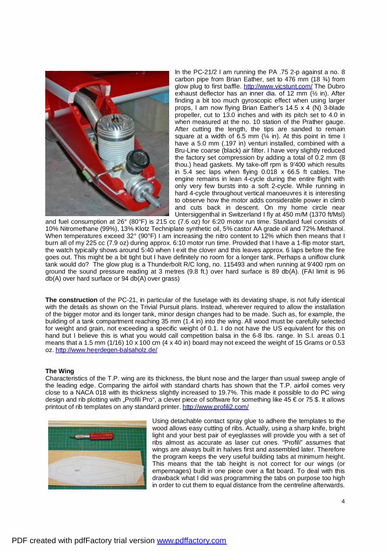
In the PC-21/2 I am running the PA .75 2-p against a no. 8 carbon pipe from Brian Eather, set to 476 mm (18 ¾) from glow plug to first baffle. http://www.vicstunt.com/ The Dubro exhaust deflector has an inner dia. of 12 mm (½ in). After finding a bit too much gyroscopic effect when using larger props, I am now flying Brian Eather’s 14.5 x 4 (N) 3-blade propeller, cut to 13.0 inches and with its pitch set to 4.0 in when measured at the no. 10 station of the Prather gauge. After cutting the length, the tips are sanded to remain square at a width of 6.5 mm (¼ in). At this point in time I have a 5.0 mm (.197 in) venturi installed, combined with a Bru-Line coarse (black) air filter. I have very slightly reduced the factory set compression by adding a total of 0.2 mm (8 thou.) head gaskets. My take-off rpm is 9'400 which results in 5.4 sec laps when flying 0.018 x 66.5 ft cables. The engine remains in lean 4-cycle during the entire flight with only very few bursts into a soft 2-cycle. While running in hard 4-cycle throughout vertical manoeuvres it is interesting to observe how the motor adds considerable power in climb and cuts back in descent. On my home circle near Untersiggenthal in Switzerland I fly at 450 m/M (1370 ft/Msl)
and fuel consumption at 26° (80°F) is 215 cc (7.6 oz) for 6:20 motor run time. Standard fuel consists of 10% Nitromethane (99%), 13% Klotz Techniplate synthetic oil, 5% castor AA grade oil and 72% Methanol. When temperatures exceed 32° (90°F) I am increasing the nitro content to 12% which then means that I burn all of my 225 cc (7.9 oz) during approx. 6:10 motor run time. Provided that I have a 1-flip motor start, the watch typically shows around 5:40 when I exit the clover and this leaves approx. 6 laps before the fire goes out. This might be a bit tight but I have definitely no room for a longer tank. Perhaps a uniflow clunk tank would do? The glow plug is a Thunderbolt R/C long, no. 115493 and when running at 9'400 rpm on ground the sound pressure reading at 3 metres (9.8 ft.) over hard surface is 89 db(A). (FAI limit is 96 db(A) over hard surface or 94 db(A) over grass) The construction of the PC-21, in particular of the fuselage with its deviating shape, is not fully identical with the details as shown on the Trivial Pursuit plans. Instead, wherever required to allow the installation of the bigger motor and its longer tank, minor design changes had to be made. Such as, for example, the building of a tank compartment reaching 35 mm (1.4 in) into the wing. All wood must be carefully selected for weight and grain, not exceeding a specific weight of 0.1. I do not have the US equivalent for this on hand but I believe this is what you would call competition balsa in the 6-8 lbs. range. In S.I. areas 0.1 means that a 1.5 mm (1/16) 10 x 100 cm (4 x 40 in) board may not exceed the weight of 15 Grams or 0.53 oz. http://www.heerdegen-balsaholz.de/ The Wing Characteristics of the T.P. wing are its thickness, the blunt nose and the larger than usual sweep angle of the leading edge. Comparing the airfoil with standard charts has shown that the T.P. airfoil comes very close to a NACA 018 with its thickness slightly increased to 19.7%. This made it possible to do PC wing design and rib plotting with „Profili Pro“, a clever piece of software for something like 45 € or 75 $. It allows printout of rib templates on any standard printer. http://www.profili2.com/
Using detachable contact spray glue to adhere the templates to the wood allows easy cutting of ribs. Actually, using a sharp knife, bright light and your best pair of eyeglasses will provide you with a set of ribs almost as accurate as laser cut ones. “Profili” assumes that wings are always built in halves first and assembled later. Therefore the program keeps the very useful building tabs at minimum height. This means that the tab height is not correct for our wings (or empennages) built in one piece over a flat board. To deal with this drawback what I did was programming the tabs on purpose too high in order to cut them to equal distance from the centreline afterwards.
PDF created with pdfFactory trial version www.pdffactory.com
5
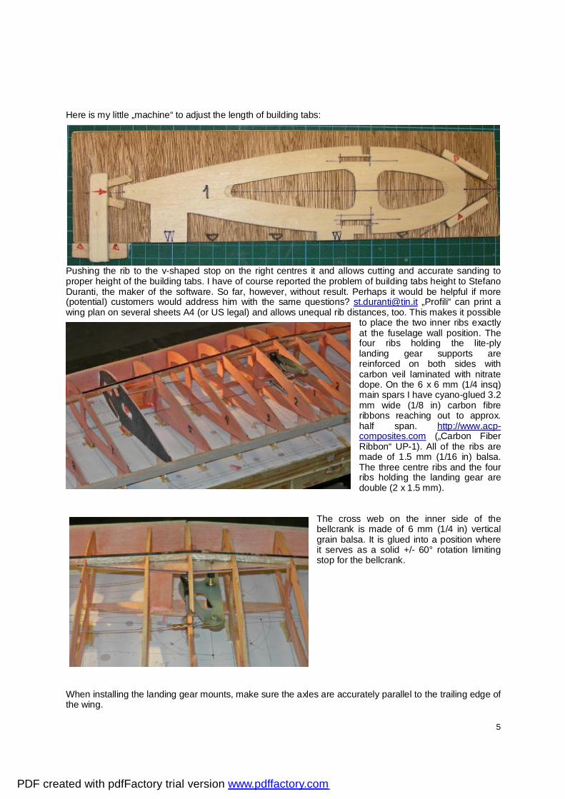
Here is my little „machine“ to adjust the length of building tabs:
Pushing the rib to the v-shaped stop on the right centres it and allows cutting and accurate sanding to proper height of the building tabs. I have of course reported the problem of building tabs height to Stefano Duranti, the maker of the software. So far, however, without result. Perhaps it would be helpful if more (potential) customers would address him with the same questions? [email protected] „Profili“ can print a wing plan on several sheets A4 (or US legal) and allows unequal rib distances, too. This makes it possible
to place the two inner ribs exactly at the fuselage wall position. The four ribs holding the lite-ply landing gear supports are reinforced on both sides with carbon veil laminated with nitrate dope. On the 6 x 6 mm (1/4 insq) main spars I have cyano-glued 3.2 mm wide (1/8 in) carbon fibre ribbons reaching out to approx. half span. http://www.acp-composites.com („Carbon Fiber Ribbon“ UP-1). All of the ribs are made of 1.5 mm (1/16 in) balsa. The three centre ribs and the four ribs holding the landing gear are double (2 x 1.5 mm).
The cross web on the inner side of the bellcrank is made of 6 mm (1/4 in) vertical grain balsa. It is glued into a position where it serves as a solid +/- 60° rotation limiting stop for the bellcrank.
When installing the landing gear mounts, make sure the axles are accurately parallel to the trailing edge of the wing.
PDF created with pdfFactory trial version www.pdffactory.com

6
The exchangeable lading gear legs are made of 3.5 mm (0.138 in) piano wire. At 22 Grams (0.77 oz.) per leg they are reasonably light and very solid. Uwe Kehnen has a source for the wire and the very light carbon wheel pants (6 Grams or 0.21 oz per piece) are available through Alexander Schrek.
The trailing edge box with vertical grain webs between the ribs adds to the torsion resistance of the wing and absorbs the considerable forces acting on the wing when flaps are deflected at full speed. The under side of the wing. All parts have been sealed against humidity by applying one coat of 75% thinned nitrate dope. An affordable weight penalty helping to prevent warps and weight pickup when flying through rain. Or while covering the wing with wet silkspan.
PDF created with pdfFactory trial version www.pdffactory.com

7
All sheetings are sealed on the inside before installation. When gluing the adjustable lead-out guide in place, make sure that the most forward position of the slider centre is at a position 10 mm (0.4 in) behind the projected Centre of Gravity (w/o fuel) of the airplane. For my PC-21 this came to 165 mm (6.5 in) from the hinge line forward.
With all upper sheetings and cap strips installed the wing, so far glued to the building board, can be separated and flipped over.
Tips are made from lightest possible blocks in halves cyano-tacked together and to the wing. After shaping the outer contour the blocks are separated using a razor blade and hollowed.
Prior and/or after installation all wood parts are sealed by applying one coat of 75% thinned nitrate dope. Adding a couple of drops of automotive base paint allows visual control of the application. Before covering apply two coats of 50% thinned nitrate dope and sand lightly with 250. Contours of all open bays need to be slightly rounded off. Wing
Area (without flaps) qdm / insq. 37.9 / 588
qty (unit or sqdm)
Weight Unit
Weight Grams
Weight
oz. Rib 1.5 mm (1/16) 24 1.5 36.0 1.27 Rib at ldg. gear position 4 4.0 16.0 0.56 Main spar 2 8.0 16.0 0.56 Shear web between main spar 20 0.3 5.0 0.18 Shear web in trailing edge box 26 0.1 2.6 0.09 Leading edge 2 7.0 14.0 0.49 Bellcrank support 3 mm (1/8) lite ply 2 6.0 12.0 0.42 Bellcrank with axle and ball link 1 29.0 29.0 1.02 Short pushrod to flaps 1 7.0 7.0 0.25 Brodak diff. flap horn with ball link 1 19.0 19.0 0.67 Hinge 8 0.5 3.6 0.13 Lead-out cable 2 5.0 10.0 0.35 Landing gear support lite ply 2 7.0 14.0 0.49 Ldg. gear cover and screws 2 3.5 7.0 0.25 Tip weight box cover and screws 1 4.0 4.0 0.14 Trailing edge 1 10.0 10.0 0.35
PDF created with pdfFactory trial version www.pdffactory.com

8
Nose sheeting 1.5 mm (1/16) 4 6.0 24.0 0.21 Centre sheeting 1.5 mm (1/16) 2 2.0 4.0 0.07 Trailing edge sheeting 1.5 mm (1/16) 2 4.6 9.2 0.32 Cap strip 44 0.1 5.3 0.19 Lead-out guide 1 5.0 5.0 0.18 Tip, inner 1 15.0 15.0 0.53 Tip, outer 1 25.0 25.0 0.9 Sealing coat 1 15.0 15.0 0.53 Glue 1 10.0 10.0 0.35 Flaps centre extension 1 2.0 2.0 0.07 Roll trim tab with hinges & horn 1 5.0 5.0 0.18 Roll trim pushrod 1 2.0 2.0 0.07 Raw structure 327 11.53 Sanding -10 -0.35 Structure, sanded 317 11.18
To increase puncture resistance all open bays are covered with Polyspan. http://www.faimodelsupply.com/starline-polyspan.htm Carefully avoiding wrinkles and sags, the Polyspan is attached dry to the wood using nitrate dope. Heat-shrink when dry. When trying to sand the transition from Polyspan to wood be careful not to sand into the Polyspan material. Extra coats of dope along the contours will be needed to prevent problems.
Finally, cover the wing with Silkspan GM paper http://www.brodak.com/ Apply wet, avoid wrinkles and bubbles and glue along the contours with nitrate dope. When fully dry apply 4 coats of 50% thinned nitrate dope. After each coat, make sure to keep the wing perfectly flat and free of torsion on the building board by putting sufficient weight on it. Let dry min. 24 hrs. and sand very lightly with 250 after 2 coats. The Empennage Using„Profili“, I have chosen the NACA 009 airfoil to draw a set of ribs combining both stabiliser and elevator rib templates in one. Again, one has to adjust the height of the building tabs. All ribs are made
from 1.5 mm (1/16) balsa and the spars are cut oversize from extra light stock and sanded straight to final dimensions.
The elevator horn is made from 3 mm (1/8) piano wire with a pair of slotted 0.8 mm (1/32) brass horns hard soldered to the wire. Prior and/or after installation all wood parts are sealed by applying one coat of 75% thinned nitrate dope. Before covering apply two coats of 50% thinned nitrate dope and sand lightly with 250. Contours of all open bays need to be slightly rounded off.
PDF created with pdfFactory trial version www.pdffactory.com

9
Stabiliser
Area (w/o elevators) qdm / insq 6.24 / 96.7
Qty. (Unit or sqdm)
Weight Unit
Weight Grams
Weight
oz. Rib 1.5 mm (1/16) 24 0.3 7.2 0.25 main spar 1 5.0 5.0 0.18 Leading edge 2 3.0 6.0 0.21 Tip 2 2.0 4.0 0.14 Centre sheeting 2 3.0 6.0 0.21 Elevators centre extension 1 4.0 4.0 0.14 Slider horn 3 mm (1/8) with screw and ball link 1 17.0 17.0
0.6
Hinge 6 0.5 2.7 0.1 Glue 1 2.0 2.0 0.07 Structure, sanded 52 1.83
Elevators
Area, both, qdm/insq 4.67 / 72.4
Qty. (Unit or sqdm)
Weight Unit
Weight Grams
Weight
oz. Rib 1.5 mm (1/16) 18 0.2 3.6 0.127 Main spar 2 2 4.0 0.14 Trailing edge 2 1 2.0 0.07 Tip 2 1.5 3.0 0.11 Centre sheeting 2 2 4.0 0.14 Horn pocket 2 1.5 3.0 0.11 Structure, both, sanded 17.6 0.62
The open bays of the empennage are covered with Polyspan, followed by covering stabiliser and elevators with silkspan GM. Apply 4 coats of 50% thinned nitrate dope. After each coat, make sure to keep the components perfectly flat and free of torsion on the building board by putting sufficient weight on it. Let dry min. 24 hrs. and sand very lightly with 250 after 2 coats.
PDF created with pdfFactory trial version www.pdffactory.com

10
The Flaps Flaps are built as 7.5 mm (0.3 in) thick flat plates consisting of 1.5 mm (1/16) top and bottom sheets with a 4.5 mm (0.18 in) Styrofoam core in between and balsa spars around. Sheeting was done with epoxy laminating resin applied very thin, using a steel spatula, on the wood only and followed by heavy compression
Flaps
Area, both, qdm/insq 7.36 / 114
Qty. (Unit or sqdm)
Weight Unit
Weight Grams
Weight oz.
Foam core 4.5 mm (0.18 in) 2 2.5 5.0 0.18 Sheeting 1.5 mm (1/16) 4 5.5 22.0 0.78 Bonding, epoxy 15 0.4 5.2 0.18 Leading edge and hinge / horn pockets 2 3.0 6.0
0.21
Trailing edge 2 2.0 4.0 0.14 Structure, both, sanded 40.2 1.42
The Fuselage It consists of motor crutch with tank compartment, side walls and bottom/top shells. The front half of the side walls are made from 3 mm (1/8) medium weight B-grain balsa, spliced to the rear part of the walls which are cut from 2 mm (5/64) light wood. The inner sides of the walls are epoxy-laminated with 68 Gr /qm (2.4 oz. sqyd) carbon cloth back to the wing trailing edge. From mid wing to the rear of the walls I have glued a structure of 3 x 6 mm (1/8 x ¼) balsa strips on the inner sides, adding stiffness and torsion resistance. On the outside, both fuselage nose and cowling are covered with 25 Gr/qm (1 oz/sqyd) glass cloth, laminated with thinned epoxy laminating resin http://www.swiss-composite.ch
PDF created with pdfFactory trial version www.pdffactory.com

11
Engine thrust line and wing/empennage incidence angles refer to the top edge of the fuselage walls. Glued to the top edge of the engine bearers is a piece of cross grain 3 mm (1/8) balsa. It is sanded conical from front to back reaching zero thickness overhead the wing. When installing the crutch flush with the top edge of the side walls what results is approx. one a degree (1°) motor down thrust. This is what it takes to compensate for the precession pitch-up moment resulting from the propeller being rotated once in 5.4 seconds around the vertical axis. (in level flight at a speed of 5.4 sec per lap)
Made from 2 x 1.5 mm (2 x 1/16) balsa plywood laminated on both sides with carbon cloth, the tank compartment floor adds considerably to stability and stiffness.
PDF created with pdfFactory trial version www.pdffactory.com

12
Service hatches are built together with their frames and glued into the side walls where needed.
At time of final assembly the wing centre line must be parallel to the top edge of the side walls within a tolerance of +/- 1.5 mm (1/16 in), when checked over a distance of approx. 60 cm or 25 in. Equally, the wing trailing edge needs to be at right angles to the fuselage centre line within the same tolerance.
In order to increase level flight stability the stabiliser is installed with a positive (Leading edge up) angle of attack of 0.5 degrees. For the PC-21 stabiliser this is equal to shimming up the leading edge by 0.8 mm or 1/32 in.
PDF created with pdfFactory trial version www.pdffactory.com

13
The four top and bottom shells are made from 2 mm (5/64) balsa wet bent over foam cores. Dimensioning and design of the fuselage allow installation of the motor, header and pipe assembly from the front side, same as tank installation. This keeps the structural integrity of the fuselage. As with all other components, the inner surfaces of the fuselage are sealed against humidity.
The dimensions of the uniflow metal fuel tank are 30 x 56 x 150 mm (1.18 x 2.2 x 5.9 in) and its capacity is 225 ccm or 7.9 oz. Due to the short nose of the PC-21 it was necessary to extend the tank compartment to the back where it reaches approx 30 mm (1.2 in) into the wing. The tank is made from 0.18 mm (7 thou.) sheet metal and tubes are copper.
I have covered the entire fuselage using Silkspan GM.
Fuselage
Qty. (Unit or sqdm)
Weight Unit
Weight Grams
Weight oz.
Sidewall 3 / 2 mm (1/8 - 5/64) 2 18 36.0 1.27 Inside carbon laminate 10 1.7 17.0 0.6 Motor mounts and cross filling braces 1 63 63.0 2.22 Top nose ring 1 6 6.0 0.21 Top nose block 1 6 6.0 0.21 Service hatch flaps, with screws 1 8 8.0 0.28 Service hatch elevators, with screws 1 7 7.0 0.25 Tank compartment floor carbon laminated 1 7 7.0 0.25 Tank shims and fixture 3 4 12.0 0.42 Inner structure reinforcement parts and pipe tunnel floor 1 8 8.0
0.28
Tail wheel support, cover and screws 1 8 8.0 0.28 Tail weight box, cover and screws 1 5 5.0 0.18 Top and bottom shell 2 mm (5/64) 4 11 44.0 1.55 Top tail block 1 4 4.0 0.14 Bottom tail block 1 5 5.0 0.18 Cowl, epoxy sealed inside 1 22 22.0 0.78 Cockpit 1 3 3.0 0.11 Canopy 1 32 32.0 1.13 Elevator pushrod with one ball link 1 13 13.0 0.46 Pipe tunnel inner seal 1 5 5.0 0.18 Pipe support and screw 1 4 4.0 0.14 Glue and fillets 1 20 20.0 0.7 Structure, sanded 328 11.57
PDF created with pdfFactory trial version www.pdffactory.com

14
The Finish In order to remain below the projected weight of 1’800 Grams (63.5 oz.) the finishing effort, both in terms of weight and time, was kept relatively low. However, no compromise was made when it comes to strength and durability of the finish. At this point, it is important to note that we have no easy access to fuel resistant butyrate dope over here in Europe which means that I do all my finishing with modern nitrate dope containing plasticiser http://winoil.ch/index2.html Take note that nitrate dope is not fuel resistant. In order to increase puncture resistance I am using Polyspan to cover open bays, followed by Silkspan GM overall. Polyspan can be heat-shrinked and does not need extra dope. Considering the gain of strength, in particular in terms of torsion, its weight of 0.21 gram per sqdm (0.7 oz. sqyd) is well worth the effort of putting it on. Because of Polyspan not really lending itself for the easy covering of compound curved objects, such as wing tips, and because the material sometimes shows tiny pinholes, overall covering with Silkspan is recommended. Four to five coats of 50% thinned nitrate dope have been applied to all covered surfaces, allowing a drying time of 24 hrs. between coats. Because all components, including fuselage side walls, have been covered before final assembly it was possible to keep them flat and free of warps all the time. Light 250 sanding was done after coats 2 and 4 or 5. Fillets have been done with a very light epoxy filler material typically being used in the light aircraft industry. Unlike many other types of filler used to do fillets it sands quite easy, almost as good as medium grade balsa. Sources for „SuperFil“ can be found at: http://www.polyfiber.com/epoxy/ For the paintwork I have used one of the current automotive 2-coat systems, available from major manufacturers such as ICI, Glasurit or Herberts-Standox. The white base paint was sprayed first, followed next day by the red trim colour and the lettering. Fuel protection was achieved by spraying 1 ½ coats of Polyurethane clear, wearing a suitable protection mask all the time. In order to save weight I have used 10% more thinner for the clear. When working with automotive 2-coat systems make sure to purchase base paints being mixed (by the supplier) for specific car types, such as, for example: „BMW - Alpine white“. Do not buy the primary base colours used by the supplier to mix individual tones because those primary paints do not cover very well.
Surface Finish Weights Gramm pro
sqdm oz. per
square foot One coat of 50% thinned nitrate dope on Silkspan over Polyspan 0.08
0.031
Pure silk Esaki No. 3 0.12 0.47 Pure silk from Ciolina Stoffe AG (Switzerland) 0.2 0.078 Polyspan, applied with nitrate dope 0.21 0.082 Silkspan GM, applied with nitrate dope 0.2 0.078 2-coat base colour white plus trim colours. Lightly applied coats. 0.35
0.137
2-components Polyurethane clear. Lightly applied 1 ½ coats. 0.4
0.157
PDF created with pdfFactory trial version www.pdffactory.com

15
Weight & Balance Multiplying the weight of a component by its distance (Arm) from a point (Datum) results in a Moment. Adding up all moments and dividing the sum of moments by the sum of weights leads to the distance of the Centre of Gravity from the Datum:
Centre of Gravity arm = Sum of Moments divided by Sum of Weights
PC/21/2 Weight & Balance (Metric) *Datum at spinner back plate
Sub-Assembly Weight
gram *Arm mm Moment grams x mm
Fuselage with rudder, painted 410 412 168823 Wing with flaps, painted 479 417 199653 Empennage, painted 102 1014 103069 Drive train 630 150 94300 Main gears with wheel pants 82 300 24600 Tail gear 7 1075 7525 Tip weight 40 400 16000 Tail trim weight 0 Nose trim weight 30 30 900 Fuel 0 180 0 Weight Gram 1780 614869 C.G. from spinner back plate (mm) 345
PC/21/2 Weight & Balance (inches) *Datum at spinner back plate
Sub-Assembly Weight
oz *Arm
in Moment oz x in Fuselage with rudder, painted 14.46 16.22 235 Wing with flaps, painted 16.9 16.42 277 Empennage, painted 3.6 39.92 144 Drive train 22.22 5.91 131 Main gears with wheel pants 2.89 11.81 34 Tail gear 0.25 42.32 11 Tip weight 1.41 15.75 22 Tail trim weight 0 0 Nose trim weight 1.06 1.18 1 Fuel 0 7.09 0 Weight oz. 62.7 855 C.G. from spinner back plate (in.) 14
The metric (Excel) version of the complete PC-21/2 W & B sheet is available on request.
PDF created with pdfFactory trial version www.pdffactory.com

16
Flight Setup The initial setup for the first flights in May 2008 was: C.G.: 24.4 % MAC (zero trim weights) or 170 mm (6.7 in) from hinge line forward. Tip weight: 30 Grams (1.06 oz) Flap to Elevator ratio: 1:1 Rake: 19 mm behind the Centre of Gravity with ¾ fuel load (as per Rake III) Prop: Brian Eather 13.5 x 4 ¼ square tip, narrow Venturi: 4.8 (.189) Pipe: Brian Eather No. 8 at 483 mm (19 in)
During the initial phase of trimming I have soon found that extending the hingeline-hingeline distance by 37 mm (1.45 in) to 500 mm (19.7 in) proofed to be counterproductive since the airplane was quite easy over controlled leading to instability when coming out of corners. It took a reduction of the elevator throw by 15 %, combined with adding 30 Grams (1.06 oz.) nose weight and smaller handle spacing to solve this problem. Also, the tip weight had to be increased to 40 Grams (1.41 oz) to eliminate hinging. When detecting yawing in the top legs of the square eights I realised that the rake
calculation as offered by the Rake III software http://www.stunthanger.com/temp/LineIIISetup.exe generates a setting for level flight only. Playing with numbers and entering values taking into account the fact that line tension overhead is 1 (one) G less than in level flight, resulted in a significantly higher number. Adjusting the rake accordingly has eliminated the yaw. The motor has never shown any sign of problems. It is very easy to needle and, in particular when I reduced the load by flying 13 in diameter instead of 13 ½, it runs in hard 4-cycle throughout all manoeuvres, only occasionally producing short bursts of a soft 2-cycle. The load-depending power change is excellent. Here is the complete setup chart as per July 2008:
PC-21/2 1’780 Grams / 63 oz (w/o fuel) Airplane Trivial Pursuit Special Edition (Ted Fancher) Fuselage shape Pilatus PC 21 Jet Trainer, SAF version Flaps flat plate 5/16 in (8 mm) Hingeline-hingeline extended to 500 mm (20in) Hingelines seal Flaps & elevators Stab incidence + 0.25° (up) Motor downthrust - 1“ (down) Roll trim Tab on outer wing C.G. empty 22.6% MAC or 175 mm (6.9 in) f. hingeline fwd. C.G. with ¼ fuel 21.2% MAC or 180 mm (7.08 in) C.G. with ¾ fuel 18.4% MAC or 188 mm (7.4 in) Lines/length 0.45 mm (0.018 in) x 20.3 m (66 ft) eyelet-eyelet Rake for level flight with ¾ fuel (2.9 G) 26 mm behind C.G. with ¾ fuel Rake for overhead flight with ¼ fuel (1.9 G) 33.5 mm or 146.5 mm behind C.G. with ¼ fuel
PDF created with pdfFactory trial version www.pdffactory.com

17
Power Train Motor PA .75 two port Compression shim Factory std. + 0.2 mm (+ 8/1000 in) Venturi Factory std. at 5.0 mm (.200 in) Glowplug Thunderbolt R/C long No 115493 Air Filter Bru-Line coarse (black) mesh Pipe plus 12 mm (1/2“) i.d. deflector Brian Eather No. 8 set to 476 mm (18 3/4 in) Take-off run noise at 3 m. / 9.8 ft 88 dbA Tank (std. uniflow metal type) 225 ccm (7.9 oz) 30 x 56 x 150 mm Fuel 10% Nitro + 13% Klotz Techniplate + 5% Castor Setup 25° C, 450 m (1470 ft msl) Propeller 3-blade Brian Eather, flat, 13 x 4.0 (at no. 10
Station Prather) Tips narrowed to ¼ in. T/O RPM 9’400 Run lean 4-cycle Lap time 5.4 sec Consumption 225 ccm for 6:40 run time (-1 Turn = 212 cc /
6:15) Tip weight assymmetry 40 Grams (1.4 oz.) Flaps - elevators throw ratio set to 1:0.85 Roll trim set to + 2° (up) Nose trim weight 30 Grams (1.05 oz) Rake set 30 mm behind C.G. with ¼ fuel (150 / 5.9“ fwd)
- PC-21/2 Peter Germann, July 20 2008 -
PDF created with pdfFactory trial version www.pdffactory.com