Tritium Transport within the TMIST-3 In-Reactor Experiment PNNL TMIST-3... · Tritium Transport...
23
Tritium Transport within the TMIST-3 In-Reactor Experiment WG LUSCHER 1 , DJ SENOR 1 , AND KK CLAYTON 2 1 Pacific Northwest National Laboratory, 2 Idaho National Laboratory Tritium Focus Group Meeting, Princeton, NJ 5-7 May 2015 1 PNNL-SA-109944
Transcript of Tritium Transport within the TMIST-3 In-Reactor Experiment PNNL TMIST-3... · Tritium Transport...

Tritium Transport within the TMIST-3 In-Reactor Experiment
WG LUSCHER1, DJ SENOR1, AND KK CLAYTON2
1Pacific Northwest National Laboratory, 2Idaho National Laboratory Tritium Focus Group Meeting, Princeton, NJ
5-7 May 2015 1 PNNL-SA-109944

Overview:
Tritium Technology Program Motivation for TMIST-3
Modeling Needs ATR Environment TMIST-3 Description Tritium Transport Initial Transport Model Initial Transport Test Summary & Future Work
2
Tritium Technology Program
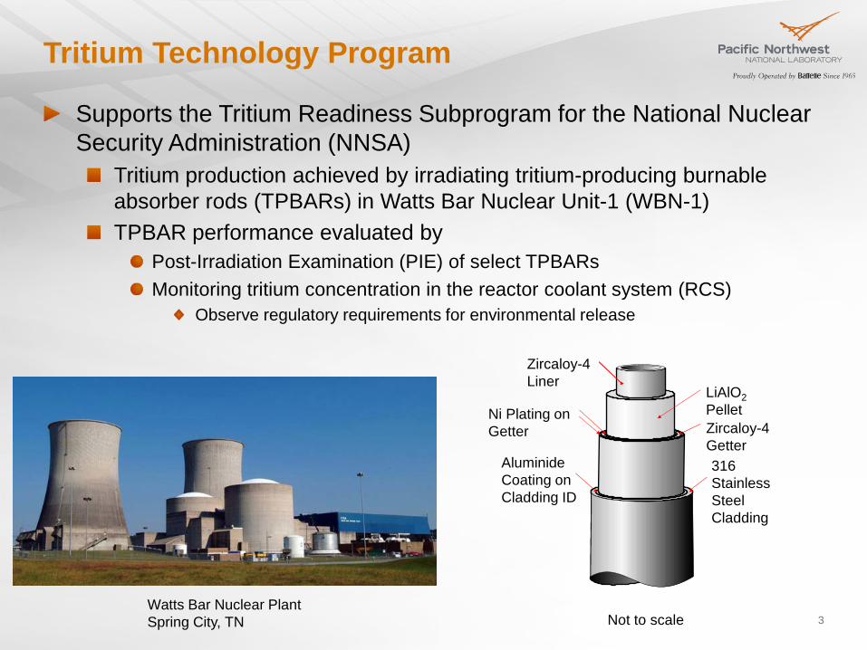
Watts Bar Nuclear Plant Spring City, TN 3
Supports the Tritium Readiness Subprogram for the National Nuclear Security Administration (NNSA)
Tritium production achieved by irradiating tritium-producing burnable absorber rods (TPBARs) in Watts Bar Nuclear Unit-1 (WBN-1) TPBAR performance evaluated by
Post-Irradiation Examination (PIE) of select TPBARs Monitoring tritium concentration in the reactor coolant system (RCS)
Observe regulatory requirements for environmental release
Zircaloy-4 Liner
316 Stainless Steel Cladding
Aluminide Coating on Cladding ID
Zircaloy-4 Getter
LiAlO2 Pellet Ni Plating on
Getter
Not to scale

Motivation for TMIST-3
4
Supports TTP Science and Technology (S&T) program Evaluate underlying mechanisms driving TPBAR performance
Past TMIST/TMED experiments have evaluated: Liner oxidation Cladding permeation Hydrogen absorption behavior
Provide data to improve TPBAR modeling capability Estimate changes in performance due to changes in:
Plant operation Component manufacture / vendors TPBAR design
Provides in-reactor data for the release and speciation of tritium from γ-lithium aluminate (γ-LiAlO2) and cermet (γ-LiAlO2 in Zr) pellets
Data collected as a function of time, burnup, and burnup rate Establish an upper limit for pellet burnup Assess release characteristics in context of TPBAR permeation

Modeling Needs
5
Tritium speciation (i.e., T2 or T2O) Interaction with adjacent components
Kinetics of release Does the apparent incubation period in RCS data result from:
Establishment of a driving equilibrium vapor pressure? Tritium retention in pellet?
Cycle 9 RCS data
incubation period
quasi steady-state
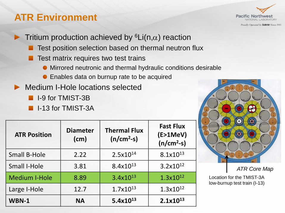
ATR Environment
Tritium production achieved by 6Li(n,α) reaction Test position selection based on thermal neutron flux Test matrix requires two test trains
Mirrored neutronic and thermal hydraulic conditions desirable Enables data on burnup rate to be acquired
Medium I-Hole locations selected I-9 for TMIST-3B I-13 for TMIST-3A
ATR Core Map Location for the TMIST-3A low-burnup test train (I-13)
ATR Position Diameter (cm)
Thermal Flux (n/cm2-s)
Fast Flux (E>1MeV) (n/cm2-s)
Small B-Hole 2.22 2.5x10¹⁴ 8.1x10¹³
Small I-Hole 3.81 8.4x10¹³ 3.2x10¹²
Medium I-Hole 8.89 3.4x10¹³ 1.3x10¹²
Large I-Hole 12.7 1.7x10¹³ 1.3x10¹²
WBN-1 NA 5.4x10¹³ 2.1x10¹³

TMIST-3 Description: Test Samples
Test specimens Standard TPBAR LiAlO2 pellets
2 µm grain size 97-98% TD 1 mm wall thickness
Large grain LiAlO2 pellets 10 µm grain size
Porous LiAlO2 pellets Small pores (~90% TD) Large pores (~85% TD)
Thin-wall LiAlO2 pellets 0.76 mm wall
Cermet pellets LiAlO2 particles in Zr matrix Four ceramic particle loadings from 10-40 v/o
7
Standard LiAlO2 pellet microstructure
Cermet pellet with 40 v/o LiAlO2

TMIST-3 Description: Capsule Design
Closed capsules Used for speciation measurements and pellet integrity/retention tests Tritium released from pellets as T2 and T2O is spatially segregated and gettered in-situ Speciation data inferred from post-irradiation examination tritium assays
Flow-Through Capsule
Closed Capsule
8
Flow-through capsules Used for time, burnup, burnup rate, and temperature dependent tritium release measurements Tritium released from pellets is carried to ex-reactor measurement system for analysis Total tritium measurement only

Tritium Transport
9
Sweep gas from flow-through capsules transports tritium to measurement system outside of reactor (ex-reactor)
Ion chambers continuously monitor tritium concentration Sweep gas proceeds from ion chambers to oxidizer columns bubblers prior to getter beds and exhaust Results from ion chamber will be used to reveal tritium release kinetics
A time lag, tlag, is expected between pellet release and ion chamber measurement
Ideally, tlag results only from the transit time between pellet and ion chamber In reality, tube wall interactions can significantly impact ion chamber response
tlag
Pellet Ion Chamber
Ideal IC response relative to step change in pellet release

Initial Transport Model
10
Tube wall interactions with T2/T2O laden gas were modeled to estimate ion chamber response time
Majority of pellet release is expected to be T2O Multiple processes can act concurrently to impact tritium transport
Adsorption Physisorption
Gas atoms or molecules are loosely bound on surface Sensitive to partial pressure and to temperature
Chemisorption Gas atoms or molecules are strongly bonded to surface Sensitive to temperature and insensitive to pressure below threshold value
Isotopic exchange Tritium and protium can “swap” or freely exchange with one another Assumed to occur between physisorbed and chemisorbed inventories

Initial Transport Model
11
Model assumptions 100’ of 1/8” Cu tubing at 150°F T2O introduced at inlet at 30 sccm Mass transfer coefficient taken from T. Shiraishi et al. for water adsoprtion/desorption on surface Output generated by WATER code developed at INL
Predictions indicate slow ion chamber response times tlag of 1 week or more can be expected, depending on release rate estimates Slow response times expected to mask details of pellet release behavior
Recommend filling physisorbed and chemisorbed inventories with a pre-test T2O flush prior to test
T. Shiraishi, S. Odoi, M. Nishikawa,Adsorption and Desorption Behavior of Tritiated Water on the Piping Materials,” Journal of Nuclear Science and Technology v.34 [7] p.687-694 (1997) M. Nishikawa, T. Takeishi, Y. Kawamura, Y. Takagi, Y. Matsumoto, “Tritium Balance in the Piping System of a Fusion Reactor,” Fusion Technology v.21 p. 878-882 (1992)

Initial Transport Experiment
12
Loop test setup in laboratory to generate data for model comparison Irradiated γ-LiAlO2 pellet used as source (T2O)
30 sccm UHP He 100’ 1/8” Cu tubing (20’ at 150°F)
Tests conducted to compare ion chamber performance and cleanup method
Ion chambers 1 & 2 use wire electrode design to minimize moisture retention Ion chamber 3 is an older design with perforated stainless steel electrodes susceptible to moisture retention Cleaning methods included
Dry He purge Heating Isotopic swamping (H2, H2O)

Initial Transport Experiment
13
Ion chamber response (IC1 vs IC2) after source (T2O) is released Response time is on the order of hours (< 1day) as opposed to a week or longer
Suggests TMIST-3 pellet release events can be resolved reasonably well without a need for T2O pre-flush
IC2 is shifted and modified relative to IC1 tlag is greater than time required for gas transit only
Consistent with tube wall interaction Shape of IC2 response suggests slower mass transfer coefficient and smaller inventory Final difference attributed to calibration uncertainty

Initial Transport Experiment
14
Overhoff Ion Chamber
•Designed to minimize T2O retention •Electrodes gold-plated •Wire electrode design, virtual wall •Triple electrode design •Bakeable to at least 150C •Used at PNNL and JET

Initial Transport Experiment
15
Summary of cleaning operations
Isotopic swamping with H2O was easily the most effective clean-up method evaluated during this test
Rapid return to baseline observed on all three ion chambers
Ion Chamber Clean-up Method # Method Description Order of Effectiveness
1 Dry He Purge Least Effective
2 Dry He purge with heat (80-130°C) Slightly more effective
3 Isotopic Swamping with H2 More effective
4 Isotopic Swamping with H2O Most effective
5 Isotopic swamping with heat No difference from 4

Summary and Future Work
16
Tube wall interactions impact transport from source to ion chamber Initial model indicated significant modifications to the lag time (several days to several weeks) and shape of the detector response Test results indicate shorter lag times (< 24 hours) can be expected
Indicates TMIST-3 pellet release characteristics can be satisfactorily resolved Eliminates need for pre-test flush with T2O
Ion chamber clean-up can be readily achieved by flushing with water vapor (H2O)
Rapid return to baseline by removing absorbed tritium from ion chamber Improved ion chamber designs exhibit less tritium build-up through absorption, but still benefit from periodic cleanup during long tests
Additional work required to reconcile modeling efforts with test results Evaluate assumptions and mass transfer coefficients in existing model Implement new code developed to evaluate transport in TMIST-3

Acknowledgments
17
Glen R. Longhurst Idaho National Laboratory/ Southern Utah University Model development and WATER code simulation
David L. Baldwin Pacific Northwest National Laboratory Test loop design and testing at Radiological Processing Laboratory

BACKUP SLIDES
25 April 2013 PNNL-SA-xxx 18

Layout of TMIST-3 gas flow system
25 April 2013 PNNL-SA-xxx 19

Components within TMIST-3 gas flow system
20
Tyne 10cc Ion Chambers
Ametek ProLine Quadrupole Mass Spec
Temperature Control Gas Mass Flow Controller Cabinet
Getter Bed Cabinet

Flow Through Capsule - Overview
Pellet
End Plug
Center TC Well
Support Tubes
Sweep Gas
Temp Control
Gas
SS Tubes
Telescoping End Plugs
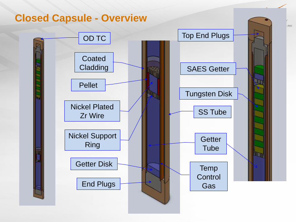
Closed Capsule - Overview
Pellet
Nickel Support Ring
Getter Disk
End Plugs
OD TC Top End Plugs
SAES Getter
Tungsten Disk
Coated Cladding
Getter Tube
SS Tube
Temp Control
Gas
Nickel Plated Zr Wire

Initial Transport Experiment
23
Tyne Ion Chamber


![Fusion Neutrons: Tritium Breeding and Impact on Wall Materials … · 2019. 7. 18. · T in CANDU reactors are discussed in [11]: around 100 g per reactor per year. Therefore, tritium](https://static.fdocuments.in/doc/165x107/60e35ff80cdd3014ac5c43a9/fusion-neutrons-tritium-breeding-and-impact-on-wall-materials-2019-7-18-t.jpg)


