TriStar Plastics Corp. - TriSteel Bearings Brochure
15
Engineering | Custom Fabrication | Manufacturing Engineered Plastic Solutions TM TriSteel TM
Transcript of TriStar Plastics Corp. - TriSteel Bearings Brochure

E n g i n e e r i n g | C u s t o m F a b r i c a t i o n | M a n u f a c t u r i n g
Engineered Plastic SolutionsTM
TriSteel TM

Services A partnership with TriStar will give you a competitive edge.
tstar.com
Our site has been praised by engineers and purchasing
agents alike. We continually strive to make this site an
indispensable engineering resource for your company.
With our in-house technical and scientific staff we
can resolve any challenge and help you find the right
engineered plastic solution.
Material Data
Use our material database to filter and compare hundreds of the
most popular high performance plastics in the industry based on
specific characteristics.
Filter, compare and call on our engineering team to help you
choose the right material and component geometry for your
application.
Educational Seminars
We offer a series of training seminars on
a variety of subjects relative to materials,
component design and applications.
Custom seminars are available for your
specific industry. Contact TriStar’s technical
department for more information.
Topic Title
High Performance Materials Pushing the Design Envelope of Plastics
Plane Bearing Technology The Application of Self-Lubricating Materials in Bearings
Composites Materials for Extreme Bearing Structural Applications
Fluoropolymers Specific Overview of Fluoropolymers and their Applications
Analytical Services
We offer a complete array of
surface analysis and materials
characterization solutions by
providing services that help
companies get the critical
information they need.
FTIR XPS AFM
Goniometry Durometer (shore A shore D]
Haze, Transmittance, Clarity (mainly transparent materials]
Tensile Pull Testing [shear and T-peel]
Compression Testing
Flexural Testing
Our analytical techniques include:
Enhanced Materials Division
From enhancing cell culture trays to
bonding dissimilar materials, the scientists
at TriStar’s Enhanced Materials Division
(EMD) can assist you in identifying
problems and recommending solutions for
your toughest surface issues.
Our expert technicians apply unique, dry,
environmentally-friendly techniques
to modify the surface of polymers,
elastomers, and films in order to
dramatically increase (or, if desired,
decrease) the bond strength of adhesives,
paint, markings, or specialty coatings.
Our services include:
Plasma Treatment
Asymmetric &
Symmetric Filtration
Membranes
Specialized
Primers & Coatings
Engineering Tools Ask the Expert
Tech Talk Blog On-line Brochures
Material Database Product Videos
Web Store Customer Portal

TriSteel TM
3
TriSteelTM is a metal backed system that is self-lubricating and is used in the most rigorous
applications. TriSteel bearings utilize special polymer liners for self-lubrication and
improved wear properties. Each material has a specific wear rate dependent on the
speed, load, temperature, lubrication and hardware of the application. The metal backing
supports liner materials made to withstand high loads, speeds and adverse environments.
The advantage of the TriSteelTM design is that even if wear-thru occurs in the liner, the
supporting interlayer is a self-lubricating material as well.
Standard Liners Standard ShellsPT (PTFE) Z (Zinc Plated Steel)AC (POM) S (Stainless)PE (PEEK) P (Copper Plated Steel)PTS (Lead Free PTFE) B (Bronze)
Example: A 16DU12 replacement would be TSI16PT12Z; a MB1008DU would be TSM10PT08Z
Refer to Stock Reference list for standard inch and metric sleeve, flange and thrust bearings.
TriSteel bearings are available in inch and metric dimensions in various combinations of liners and backing materials.
When ordering TriSteel bearings follow the format and codes as shown below.
1
T r i S t e e l
2
G a u g e
I (inch in 1/16”)
M (metric in mm)
3
I D
4
L i n e r
PT (PTFE)
AC (POM)
PE (PEEK)
PTS (Lead Free PTFE)
5
L e n g t h
6
B a c k i n g
Z (Zinc Plated Steel)
S (Stainless)
P (Copper Plated Steel)
B (Bronze)
TS GA ID LI LE BA = TS-GA-ID-LI-LE-BA
All TriSteels are 100% Lead Free
Note: AC, AT and PE liners are not available with stainless shells.
PR (Modified PTFE)P4 (High Speed Recip.)
PR (Modified PTFE)
P4 (High Speed Recip.)

TR
IS
TA
R
PL
AS
TI
CS
C
OR
P.
4
Property Units PT AC PE (PTFE) (POM) (PEEK)
P Factor
Steady Unidirectional loads, radial psi 20,000 20,000 26,000
Steady Unidirectional loads, oscillating psi 20,000 10,000 26,000
Steady, Continuous rotation, oscillation psi 8,000 10,000 13,500
Dynamic Continuous rotation, oscillation psi 8,000 6,000 8,800
Maximum Static Load psi 36,000 36,000 40,000
V Factor
Maximum Speed - Unlubricated fpm 1,000 Consult with TriStar Engineering
Maximum Speed - Lube / Oil fpm 2,000 500 2,000
Maximum Speed - Lube / Grease fpm 2,000 100 2,000
Maximum PV Limits psi/fpm 50,000 80,000 100,000
Impact Strength - Notched ft-lbs/in. >20 >20 >20
Coefficient of Friction Dynamic - Dry .08 - .12 .15 - .20 .15 - .20
Wear Factor Kx10-10 9 21 5
Operating Temperature
Minimum °F -300 -40 -140
Maximum - Continuous °F 535 210 500
Coefficient of Thermal Expansion (x10- 6)
Parallel to Surface in/in/°F 6 18 4.5
Thermal Conductivity BTU/hr/ft 2/°F/in 288 30 28
Water Absorption - 24 hour saturation % 0 0.02 0.15
Liner Thickness in 0.002 .018 - .020 .018 - .020
Benefits
Cost Competitive
Improved Wear Properties
Stable
No Lubrication Needed
Available in Inch and
Metric Dimensions
Applications
Agricultural Equipment
Hydraulic Components
Aircraft/Aerospace
Automotive
Construction Equipment
General Engineering
TriSteel bearings are produced by impregnating a self-lubricating, polymer liner
into a sintered porous bronze interlayer. The steel backing material provides
structural and mechanical support for the bonding layer and the bearing surface.
The steel backing can be zinc or copper plated or stainless steel can be used for
maximum corrosion resistance.
Bearing Surface
Backing Steel
ImpregnatedLayer
Porous BronzeLayer
TR
IS
TA
R
PL
AS
TI
CS
C
OR
P.
5
PT – Sintered porous bronze on metal substrate with
PTFE calendared into the dynamic wear surface. High
PV, self lubricating and long wear life. Commonly used
in lift and tilt applications in construction, material
handling, textile, hydraulic components, agriculture
and forestry machinery.
AC – Sintered porous bronze on metal substrate
with POM calendared into the dynamic wear surface.
Requires boundary lubrication for optimum perform-
ance. High PV rating, low speeds. Commonly used in
mining equipment, rolling mills, automotive chassis
components and other applications where bronze
bushings are utilized.
PM – Special modified PTFE heavy liner with
enhanced wear properties. Used in linear motion
devices where lubrication is not desirable. Also used
in automotive shock and strut applications where
high speed linear rods can experience high side
loading. Available in rod or piston configurations.
PE – Modified PEEK with self lubricating additives
for applications where chemicals may be utilized.
Excellent wear in both wet or dry applications.
Available with a bronze substrate for use
as chemical pump or valve bushings. Extra thick
liner allows for slight modifications for shaft
misalignment.
PR – No lead, enhanced PTFE liner for dampening
devices, hydraulic motors, automotive lift and pivot
devices and linear motion equipment. Popular use is
for bicycle and motorcycle shock absorbers as piston
and rod wear bearings. Exceptional wear properties in
unlubricated service. Service equivalent to DP4 grade.
AT – Thicker POM liner with PTFE lubricant added for
unlubricated service. Used extensively in ski lift oper-
ations for pivot points on towers and chair clips. Also
useful in cranes, textile machines, printing equipment
and light duty hoists. Service equivalent to DS grade.
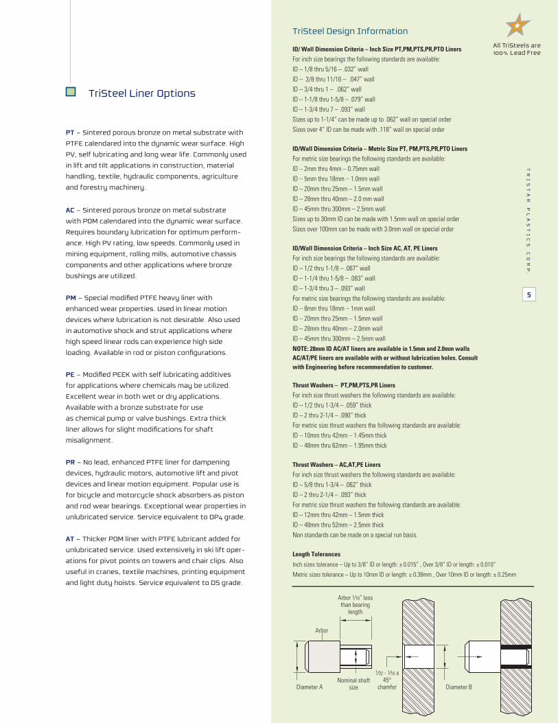
TriSteel Liner Options
Arbor 1⁄16” less than bearing
length
Arbor
Diameter A Diameter BNominal shaft
size
1⁄32 - 1⁄16 x 45°
chamfer
TriSteel Design Information
ID/ Wall Dimension Criteria – Inch Size PT,PM,PTS,PR,PTO Liners
For inch size bearings the following standards are available:ID – 1/8 thru 5/16 – .032” wallID – 3/8 thru 11/16 – .047” wallID – 3/4 thru 1 – .062” wallID – 1-1/8 thru 1-5/8 – .079” wallID – 1-3/4 thru 7 – .093” wallSizes up to 1-1/4” can be made up to .062” wall on special orderSizes over 4” ID can be made with .118” wall on special order
ID/Wall Dimension Criteria – Metric Size PT, PM,PTS,PR,PTO Liners
For metric size bearings the following standards are available:ID – 2mm thru 4mm – 0.75mm wallID – 5mm thru 18mm – 1.0mm wallID – 20mm thru 25mm – 1.5mm wallID – 28mm thru 40mm – 2.0 mm wallID – 45mm thru 300mm – 2.5mm wallSizes up to 30mm ID can be made with 1.5mm wall on special orderSizes over 100mm can be made with 3.0mm wall on special order
ID/Wall Dimension Criteria – Inch Size AC, AT, PE Liners
For inch size bearings the following standards are available:ID – 1/2 thru 1-1/8 – .067” wallID – 1-1/4 thru 1-5/8 – .083” wallID – 1-3/4 thru 3 – .093” wallFor metric size bearings the following standards are available:ID – 8mm thru 18mm – 1mm wallID – 20mm thru 25mm – 1.5mm wallID – 28mm thru 40mm – 2.0mm wallID – 45mm thru 300mm – 2.5mm wallNOTE: 28mm ID AC/AT liners are available in 1.5mm and 2.0mm walls
AC/AT/PE liners are available with or without lubrication holes. Consult
with Engineering before recommendation to customer.
Thrust Washers – PT,PM,PTS,PR Liners
For inch size thrust washers the following standards are available:ID – 1/2 thru 1-3/4 – .059” thickID – 2 thru 2-1/4 – .090” thickFor metric size thrust washers the following standards are available:ID – 10mm thru 42mm – 1.45mm thickID – 48mm thru 62mm – 1.95mm thick
Thrust Washers – AC,AT,PE Liners
For inch size thrust washers the following standards are available:ID – 5/8 thru 1-3/4 – .062” thickID – 2 thru 2-1/4 – .093” thickFor metric size thrust washers the following standards are available:ID – 12mm thru 42mm – 1.5mm thickID – 48mm thru 52mm – 2.5mm thickNon standards can be made on a special run basis.
All TriSteels are 100% Lead Free
Length Tolerances
Inch sizes tolerance – Up to 3/8” ID or length: ± 0.015” , Over 3/8” ID or length: ± 0.010”
Metric sizes tolerance – Up to 10mm ID or length: ± 0.38mm , Over 10mm ID or length: ± 0.25mm

TR
IS
TA
R
PL
AS
TI
CS
C
OR
P.
6
Contunues on next page
TriSteel Installation Dimensions for PT, PTS, PM, and PR LinersTri-Star Part N0. Shaft Dia Length Housing Bore Shaft Dim’s Installed ID
TSI06XX06X 3/8” 3/8” .4684/.4691 .3740/.3731 .3742/.3769
TSI06XX08X 3/8” 1/2” .4684/.4691 .3740/.3731 .3742/.3769
TSI06XX12X 3/8” 3/4” .4684/.4691 .3740/.3731 .3742/.3769
TSI08XX06X 1/2” 3/8” .5934/.5941 .4990/.4980 .4992/.5019
TSI08XX08X 1/2” 1/2” .4990/.4980 .4992/.5019
TSI08XX10X 1/2” 5/8” .4990/.4980 .4992/.5019
TSI08XX14X 1/2” 7/8” .4990/.4980 .4992/.5019
TSI10XX08X 5/8” 1/2” .7184/.7192 .6240/.6230 .6242/.6270
TSI10XX10X 5/8” 5/8” .7184/.7192 .6240/.6230 .6242/.6270
TSI10XX12X 5/8” 3/4” .7184/.7192 .6240/.6230 .6242/.6270
TSI10XX14X 5/8” 7/8” .7184/.7192 .6240/.6230 .6242/.6270
TSI12XX12X 3/4” 3/4” .8747/.8755 .7491/.7479 .7493/.7525
TSI12XX16X 3/4” 1” .8747/.8755 .7491/.7479 .7493/.7525
TSI14XX12X 7/8” 3/4” .9997/1.0005 .8741/.8729 .8743/.8775
TSI14XX16X 7/8” 1” .9997/1.0005 .8741/.8729 .8743/.8775
TSI16XX12X 1” 3/4” 5200.1/3999. 9799./1999. 5521.1/7421.1
TSI16XX16X 1” 1” 5200.1/3999. 9799./1999. 5521.1/7421.1
TSI18XX12X 1-1/8” 3/4” 8721.1/0421.1 6221.1/8321.1 8182.1/8082.1
TSI18XX16X 1-1/8” 1” 8721.1/0421.1 6221.1/8321.1 8182.1/8082.1
TSI20XX12X 1-1/4” 3/4” 8252.1/0942.1 2742.1/8842.1 8604.1/8504.1
TSI20XX16X 1-1/4” 1” 8252.1/0942.1 2742.1/8842.1 8604.1/8504.1
TSI22XX16X 1-3/8” 1” 8135.1/8035.1 1.3722/1.3738 1.3740/1.3778
8773.1/0473.1 2273.1/8873.1 8135.1/8035.1 ”2/1-1 ”8/3-1 X42XX22IST
TSI24XX16X 1-1/2” 1” 8205.1/0994.1 2794.1/8894.1 8656.1/8556.1
8205.1/0994.1 2794.1/8894.1 8656.1/8556.1 ”2/1-1 ”2/1-1 X42XX42IST
TSI24XX32X 1-1/2” 2” 8205.1/0994.1 2794.1/8894.1 8656.1/8556.1
TSI26XX16X 1-5/8” 1” 8726.1/0426.1 2226.1/8326.1 8187.1/8087.1
8726.1/0426.1 2226.1/8326.1 8187.1/8087.1 ”2/1-1 ”8/5-1 X42XX62IST
TSI26XX32X 1-5/8” 2” 8726.1/0426.1 2226.1/8326.1 8187.1/8087.1
TSI28XX16X 1-3/4” 1” 5357.1/9847.1 1747.1/7847.1 1839.1/1739.1
5357.1/9847.1 1747.1/7847.1 1839.1/1739.1 ”2/1-1 ”4/3-1 X42XX82IST
TSI28XX32X 1-3/4” 2” 5357.1/9847.1 1747.1/7847.1 1839.1/1739.1
TSI30XX16X 1-7/8” 1” 7878.1/9378.1 1278.1/7378.1 3360.2/1260.2
7878.1/9378.1 1278.1/7378.1 3360.2/1260.2 ”8/7-1 ”8/7-1 X03XX03IST
7878.1/9378.1 1278.1/7378.1 3360.2/1260.2 ”4/1-2 ”8/7-1 X63XX03IST
TSI32XX16X 2” 1” 9699.1/7899.1 3881.2/1781.2 1.9989/2.0037
TSI32XX24X 2” 7300.2/9899.1 9699.1/7899.1 3881.2/1781.2 ”2/1-1
TSI32XX32X 2” 2” 7300.2/9899.1 9699.1/7899.1 3881.2/1781.2
TSI32XX40X 2” 7300.2/9899.1 9699.1/7899.1 3881.2/1781.2 ”2/1-2
TSI36XX32X 2-1/4” 2” 3752.2/9052.2 9842.2/7052.2 7734.2/5634.2
3752.2/9052.2 9842.2/7052.2 7734.2/5634.2 ”4/1-2 ”4/1-2 X63XX63IST
3752.2/9052.2 9842.2/7052.2 7734.2/5634.2 ”2/1-2 ”4/1-2 X04XX63IST
TSI36XX48X 2-1/4” 3” 3752.2/9052.2 9842.2/7052.2 7734.2/5634.2
TSI40XX32X 2-1/2” 2” 7705.2/3105.2 3994.2/1105.2 1886.2/9686.2
7705.2/3105.2 3994.2/1105.2 1886.2/9686.2 ”2/1-2 ”2/1-2 X04XX04IST
TSI40XX48X 2/1-2” 3” 7705.2/3105.2 3994.2/1105.2 1886.2/9686.2
TSI40XX56X 7705.2/3105.2 3994.2/1105.2 1886.2/9686.2 ”2/1-3 ”2/1-2
TSI44XX32X 2-3/4” 2” 6657.2/2057.2 2847.2/0057.2 0739.2/8539.2
6657.2/2057.2 2847.2/0057.2 0739.2/8539.2 ”2/1-2 ”4/3-2 X04XX44IST
TSI44XX48X 2-3/4” 3” 6657.2/2057.2 2847.2/0057.2 0739.2/8539.2
6657.2/2057.2 2847.2/0057.2 0739.2/8539.2 ”2/1-3 ”4/3-2 X65XX44IST
TSI48XX32X 3” 2” 8600.3/2000.3 2899.2/0000.3 2781.3/8581.3
TSI48XX48X 3” 3” 8600.3/2000.3 2899.2/0000.3 2781.3/8581.3
TSI48XX60X 3” 8600.3/2000.3 2899.2/0000.3 2781.3/8581.3 ”4/3-3
8605.3/2005.3 8794.3/0005.3 2786.3/8586.3 ”2/1-2 ”2/1-3 X04XX65IST
.5934/.5941
.5934/.5941
.5934/.5941

TR
IS
TA
R
PL
AS
TI
CS
C
OR
P.
7
TriSteel Installation Dimensions for PT, PTS, PM, and PR Liners continued
Tri-Star Part N0. Shaft Dia Length Housing Bore Shaft Dim’s Installed ID
TSI56XX48X 3-1/2” 3” 3.6858/3.6872 3.5000/3.4978 3.5002/3.5068
TSI56XX60X 3-1/2” 3-3/4” 3.6858/3.6872 3.5000/3.4978 3.5002/3.5068
TSI64XX48X 4” 3” 4.1858/4.1872 4.0000/3.9978 4.0002/4.0068
TSI64XX60X 4” 3-3/4” 4.1858/4.1872 4.0000/3.9978 4.0002/4.0068
TSI64XX76X 4” 4-3/4” 4.1858/4.1872 4.0000/3.9978 4.0002/4.0068
TSI80XX48X 5” 3” 5.1844/5.1860 4.9986/4.9961 4.9988/5.0056
TSI80XX60X 5” 3-3/4” 5.1844/5.1860 4.9986/4.9961 4.9988/5.0056
TSI96XX48X 6” 3” 6.1858/6.1874 6.0000/5.9975 6.0002/6.0070
TSI96XX60X 6” 3-3/4” 6.1858/6.1874 6.0000/5.9975 6.0002/6.0070
TSI112XX60X 7” 3-3/4” 7.1812/7.1830 6.9954/6.9929 6.9956/7.0026
Other sizes are available in all liner styles upon request.
TriSteel Installation Dimensions for AC, AT and PE LinersRECOMMENDED
Tri-Star Part No Shaft Dia Length Housing Bore Shaft Dim’s Installed ID
TSI08XX06X 1/2” 3/8” .5934/.5941 .4990/.4980 .4992/.5019
TSI08XX08X 1/2” 1/2” .5934/.5941 .4990/.4980 .4992/.5019
TSI10XX10X 5/8” 5/8” .7184/.7192 .6240/.6230 .6242/.6270
TSI10XX12X 5/8” 3/4” .7184/.7192 .6240/.6230 .6242/.6270
TSI12XX12X 3/4” 3/4” .8846/.8854 .7500/.7488 .7508/.7540
TSI12XX16X 3/4” 1” .8846/.8854 .7500/.7488 .7508/.7540
TSI14XX12X 7/8” 3/4” 1.0097/1.0105 .8750/.8738 .8759/.8791
TSI14XX16X 7/8” 1” 1.0097/1.0105 .8750/.8738 .8759/.8791
TSI16XX12X 1” 3/4” 1.1348/1.1356 1.0000/0.9988 1.0010/1.0042
TSI16XX16X 1” 1” 1.1348/1.1356 1.0000/0.9988 1.0010/1.0042
TSI18XX12X 1-1/8” 3/4” 1.2598/1.2606 1.1250/1.1238 1.1260/1.1292
TSI18XX16X 1-1/8” 1” 1.2598/1.2606 1.1250/1.1238 1.1260/1.1292
TSI20XX12X 1-1/4” 3/4” 1.4160/1.4170 1.2500/1.2484 1.2512/1.2550
TSI20XX16X 1-1/4” 1” 1.4160/1.4170 1.2500/1.2484 1.2512/1.2550
TSI22XX16X 1-3/8” 1” 1.5410/1.5420 1.3750/1.3734 1.3762/1.3800
TSI22XX24X 1-1/2” 1-1/2” 1.5410/1.5420 1.3750/1.3734 1.3762/1.3800
TSI24XX16X 1-1/2” 1” 1.6660/1.6670 1.5000/1.4984 1.5012/1.5050
TSI24XX24X 1-1/2” 1-1/2” 1.6660/1.6670 1.5000/1.4984 1.5012/1.5050
TSI24XX32X 1-1/2” 2” 1.6660/1.6670 1.5000/1.4984 1.5012/1.5050
TSI26XX16X 1-5/8” 1” 1.7910/1.7920 1.6250/1.6234 1.6262/1.6300
TSI26XX24X 1-5/8” 1-1/2” 1.7910/1.7920 1.6250/1.6234 1.6262/1.6300
TSI26XX32X 1-5/8” 2” 1.7910/1.7920 1.6250/1.6234 1.6262/1.6300
TSI28XX16X 1-3/4” 1” 1.9371/1.9381 1.7500/1.7484 1.7515/1.7577
TSI28XX24X 1-3/4” 1-1/2” 1.9371/1.9381 1.7500/1.7484 1.7515/1.7577
TSI28XX32X 1-3/4” 2” 1.9371/1.9381 1.7500/1.7484 1.7515/1.7577
TSI30XX16X 1-7/8” 1” 2.0621/2.0633 1.8750/1.8734 1.8765/1.8829
TSI30XX24X 1-7/8” 1-1/2” 2.0621/2.0633 1.8750/1.8734 1.8765/1.8829
TSI30XX32X 1-7/8” 2” 2.0621/2.0633 1.8750/1.8734 1.8765/1.8829
TSI30XX36X 1-7/8” 2-1/4” 2.0621/2.0633 1.8750/1.8734 1.8765/1.8829
TSI32XX16X 2” 1” 2.1871/2.1883 2.0000/1.9982 2.0015/2.0079
TSI32XX24X 2” 1-1/2” 2.1871/2.1883 2.0000/1.9982 2.0015/2.0079
TSI32XX32X 2” 2” 2.1871/2.1883 2.0000/1.9982 2.0015/2.0079
TSI40XX24Z 2-1/2” 1-1/2” 2.6871/2.6883 2.5000/2.4982 2.5015/2.0079
TSI40XX32X 2-1/2” 2” 2.6871/2.6883 2.5000/2.4982 2.5015/2.0079
TSI40XX40X 2-1/2” 2-1/2” 2.6871/2.6883 2.5000/2.4982 2.5015/2.0079
TSI48XX24X 3” 1-1/2” 3.1875/3.1889 3.0000/2.9982 3.0019/3.0085
TSI48XX32X 3” 2” 3.1875/3.1889 3.0000/2.9982 3.0019/3.0085
TSI48XX40X 3” 2-1/2” 3.1875/3.1889 3.0000/2.9982 3.0019/3.0085
TSI48XX48X 3” 3” 3.1858/3.1889 3.0000/2.9982 3.0019/3.0085
AC and PE liners come standard with lubrication holes. PE liners also available without holes on request.
All TriSteels are 100% Lead Free

TriSteel Metric Installation Dimensions for PT, PTS, PM, and PR Liners
ID OD Shaft Dia Housing Bore Wall Thickness
Min Max
6 8 6 -0.013 -0.028 8 +0.015
0.980 1.005
8 10 8 -0.013 -0.028 10 +0.015
10 12 10 -0.016-0.034 12 +0.018
12 14 12 -0.016-0.034 14 +0.018
13 15 13 -0.016-0.034 15 +0.018
14 16 14 -0.016-0.034 16 +0.018
15 17 15 -0.016-0.034 17 +0.018
16 18 16 -0.016-0.034 18 +0.018
17 19 17 -0.016-0.034 19 +0.021
18 20 18 -0.016-0.034 20 +0.021
20 23 20 -0.020-0.041 23 +0.021
1.475 1.505
22 25 22 -0.020-0.041 25 +0.021
24 27 24 -0.020-0.041 27 +0.021
25 28 25 -0.020-0.041 28 +0.021
28 32 28 -0.020-0.041 32 +0.025
1.970 2.005
30 34 30 -0.020-0.041 34 +0.025
32 36 32 -0.025-0.050 36 +0.025
35 39 35 -0.025-0.050 39 +0.025
38 42 38 -0.025-0.050 42 +0.025
40 44 40 -0.025-0.050 44 +0.025
45 50 45 -0.025-0.050 00 +0.025
2.460 2.505
50 55 50 -0.030-0.060 55 +0.030
55 60 55 -0.030-0.060 60 +0.030
60 65 60 -0.030-0.060 65 +0.030
65 70 65 -0.030-0.060 70 +0.030
70 75 70 -0.030-0.060 75 +0.030
75 80 75 -0.030-0.060 80 +0.030
80 85 80 -0.035 85 +0.035
2.440 2.490
85 90 85 -0.035 90 +0.035
90 95 90 -0.035 95 +0.035
95 100 95 -0.035 100 +0.035
100 105 100 -0.035 105 +0.035
105 110 105 -0.035 110 +0.035
110 115 110 -0.035 115 +0.035
120 125 120 -0.04 125 +0.035
2.415 2.465
125 130 125 -0.04 130 +0.040
130 135 130 -0.04 135 +0.040
140 145 140 -0.04 145 +0.040
150 155 150 -0.04 155 +0.040
160 165 160 -0.04 165 +0.040
180 185 180 -0.046 185 +0.046
190 195 190 -0.046 195 +0.046
200 205 200 -0.046 205 +0.046
220 225 220 -0.046 225 +0.046
250 255 250 -0.052 255 +0.052
260 265 260 -0.052 265 +0.052
280 285 280 -0.052 285 +0.052
300 305 300 -0.052 305 +0.052
See Page 3 for the full chart showing how
our part numbers are built (including liner and
backing abbreviations].
TSM25PT28-23.5Z
T r i S t e e l
M e t r i c
I D
L i n e r
( P T F E )
O D
L e n g t h
B a c k i n g
( Z i n c )
Build a part number using the table data at left,
plus the liner material, backing material, and
your desired length.
Part Number Guide
TR
IS
TA
R
PL
AS
TI
CS
C
OR
P.
8

TriSteel Metric Installation Dimensions for AC, AT, and PE Liners
ID OD Shaft Dia Housing Bore Wall Thickness
Min Max
10 12 10 -0.022 12 +0.018
0.955 0.980
12 14 12 -0.027 14 +0.018
14 16 14 -0.027 16 +0.018
15 17 15 -0.027 17 +0.018
16 18 16 -0.027 18 +0.018
18 20 18 -0.027 20 +0.021
20 23 20 -0.033 23 +0.021
1.445 1.47522 25 22 -0.033 25 +0.021
25 28 25 -0.033 28 +0.021
28 32 28 -0.033 32 +0.025
1.935 1.97030 34 30 -0.033 34 +0.025
35 39 35 -0.039 39 +0.025
40 44 40 -0.039 44 +0.025
45 50 45 -0.039 50 +0.025
2.415 2.460
50 55 50 -0.039 55 +0.030
55 60 55 -0.046 60 +0.030
60 65 60 -0.046 65 +0.030
65 70 65 -0.046 70 +0.030
70 75 70 -0.046 75 +0.030
75 80 75 -0.046 80 +0.030
80 85 80 -0.046 85 +0.035
2.385 2.450
85 90 85 -0.054 90 +0.035
90 95 90 -0.054 95 +0.035
100 105 100 -0.054 105 +0.035
105 110 105 -0.054 110 +0.035
110 115 110 -0.054 115 +0.035
120 125 120 -0.054 125 +0.040
125 130 125 -0.063 130 +0.040
130 135 130 -0.063 135 +0.040
140 145 140 -0.063 145 +0.040
150 155 150 -0.063 155 +0.040
160 165 160 -0.063 165 +0.040
170 175 170 -0.063 175 +0.040
180 185 180 -0.063 185 +0.046
190 195 190 -0.072 195 +0.046
200 205 200 -0.072 205 +0.046
220 225 220 -0.072 225 +0.046
240 245 240 -0.072 245 +0.046
250 255 250 -0.072 255 +0.052
260 265 260 -0.081 265 +0.052
280 285 280 -0.081 285 +0.052
300 305 300 -0.081 305 +0.052
See Page 3 for the full chart showing how
our part numbers are built (including liner and
backing abbreviations].
TSM25PT28-23.5Z
T r i S t e e l
M e t r i c
I D
L i n e r
( P T F E )
O D
L e n g t h
B a c k i n g
( Z i n c )
Build a part number using the table data at left,
plus the liner material, backing material, and
your desired length.
Part Number Guide
TR
IS
TA
R
PL
AS
TI
CS
C
OR
P.
5
TR
IS
TA
R
PL
AS
TI
CS
C
OR
P.
9

1 T e m p e r a t u r e
All plastics are affected by ambient heat and have a
maximum continuous service temperature. The maximum
continuous service temperature is not a melting point, but
is the highest temperature at which a material will retain
physical integrity. Important: Note that elevated tempera-
tures affect material properties in a negative manner and
should be carefully reviewed before use.
2 T e m p e r a t u r e V a r i a t i o n
All plastic materials have coefficients of thermal expansion.
Measured in in/in/°F, plastic materials vary greatly not only
from each other, but in some cases ten times that of metallic
counter parts. As a result, we consider temperature
variations. Components should be designed to meet
required service temperature. Not doing so may result in
premature failure.
3 E n v i r o n m e n t a l C o n d i t i o n s
Always consider the following environmental conditions
under which the material must operate:
• Contact with debris such as sand, grit or dust
• Contact with chemicals such as strong acids,
bases and caustics
• Contact with water, constant spray or wash downs
• FDA or USDA compliance
• Thermal conductivity
• Radiation exposure
• Microwave exposure
4 O t h e r C o n s i d e r a t i o n s
• Size and shape availability
• Material cost/economy
• Machinability
• Standard or custom runs
• Custom compounds
Material Selection Process (MSP)
In all plastic component designs, material selection is critical. During the selection process,
one should consider the following factors to ensure the best possible selection.
TR
IS
TA
R
PL
AS
TI
CS
C
OR
P.
10
tstar.com Visit our interactive online material database to research and compare various plastic materials.
If you have questions regarding which materials are appropriate for your project, just reach out
via our Ask the Expert page and our engineering team will assist you.

Plastic Material Shape Availability Machinability Serv Temp Characteristics / AttributesRod Sheet Rating 1-10 Long/Short Dia Thickness 1=Easy Degrees F
ULTRACOMP UC200 Tubing 1/8 to 3 3 266/360 High Load / Impact-Vibration Resistant / Composite
ULTRACOMP UC300 Tubing 1/8 to 3 3 266/360 Lowest Friction / Chemical Resistant / High load
ULTRACOMP UC400 Tubing 1/8 to 3 3 266/360 Moly lubricant / Slow Rotary / Salt Water Applications
ULTRACOMP UC500 Tubing 1/8 to 3 3 266/360 Bearing Grade Blended Fiber / Bearing Grade Composite
ABS 3/16 to 8 1/4 to 4 1 140/210 General Purpose / Economical / Machinable / Moldable
ACETAL / DELRIN 1/8 to 12 .010 to 4 1 195 Machinable / Economical / Good Wear / FDA / USDA
ACETRON 1/4 to 6 1/4 to 2 1 180 Acetal / Machinable / Wear Resistance
ACRYLIC 1/16 to 6 1/32 to 3 5 140/200 Optically Clear / Colors / Machinable / Formable
CELAZOLE / PBI 1 to 4-3/4 3/8 to 2 8 650/1000 Highest Temp / Chemically Resistant / High PV
DELRIN AF 3/16 to 8 1/32 to 3 1 185/300 PTFE Filled Acetal / Low Friction / Brown
DELRIN 500CL 1/2 to 3 1/4 to 4 1 180/300 Chemically Lubricated Acetal / Low Friction
ERTALYTE / ERTALYTE TX* 3/16 to 8 1/4 to 4 1 210 PET | Bearing Grade* / Good Wear / FDA / White
FEP 1/16 to 6 .005 to3 3 400 Fluoropolymer / Excellent Chemical Resistance
FLUOROSINT 207* / 500 1/2 to 8-3/4 1/4 to 3 3 500 Family of Filled PTFE / High Thermal Stability / FDA*
HYDEX 4101 & 4101L* 1/2 to 6 3/8 to 4 1 220 PBT | PTFE Filled* / FDA-USDA / Low Friction / White
HYDEX FGA 1/2 to 4 3/8 to 2 1 185/300 Teflon Filled Delrin / FDA / USDA / Low Friction
HYDLAR ZF 1/4 to 5 1/4 to 2 5 230/300 Aramid Fiber Filled Nylon / Wear Resistant
KYNAR / PVDF 1/4 to 10 1/4 to 4 2 122/230 Fluoropolymer / Excellent Chemical Resistance
MICARTA C & L 1/32 to 10 1/32 to 8 8 257 Phenolic Resin / Cloth Fabric Matrix / Laminate
MICARTA G-10 & G-11* 1/32 to 5 .005 to 5 10 284/356 Epoxy | Silicone* / Woven Fiberglass Matrix / Laminate
MICARTA XXX 1/32 to 2 1/32 to 5 8 284 Phenolic Resin / Paper Matrix / Laminate
NORYL EN265 3/8 to 8 1/4 to 4 2 195/375 PPO & Styrene Alloy / Good Creep Resistance
NYLATRON 1/32 to 2 .010 to 4 1 200 Modified Nylon Type 66 / Cast Type 6 / Impact and wear
NYLON 66 1/32 to 6 .010 to 3 1 210 Economical / Good Wear / High Impact Strength
PCTFE / KEL-F 1/16 to 6 .005 to 2 3 400 Chemical Resistant / Heat Resistant / High Temp
PEEK 1/4 to 4 1/4 to 2-1/2 5 480 Autoclavable / Chemical & Steam Resistant
PFA / NEOFLON 1/16 to 3 .002 to 3 3 500 Chemical Resistant / Heat Resistant / High Temp
POLYCARBONATE 1/32 to 15 1/32 to 4 3 210/265 Good Machinability / Transparent / High Rigidity
POLYETHYLENE 1/32 to 18 .002 to 10 1 140/175 General Purpose / Economical / Chemical Resistant
POLYIMIDE / MELDIN 1 to 4-3/4 3/8 to 2 7 600 High Temp / Wear Resistance / High PV / Low Outgas
POLYPROPYLENE 1/4 to 16 .010 to 10 1 160/230 Chemically Resistant / Weldable / Economical
POLYSULFONE / UDEL 3/16 to 8 1/4 to 4 1 300/340 Autoclavable / Chemically Resistant / Heat Resistant
PVC / CPVC* 1/4 to 13-3/4 3/32 to 4 1 155 Weldable / Economical / Chemical Resistant / Hi Temp*
REXOLITE 1/16 to 9 1/32 to 6 3 212 Crosslinked Polystyrene / High Frequency Dielectric
RULON 123 3/16 to13 .010 to 2 3 550 Filled PTFE / FDA / USDA / High V / Inert / Black
RULON 142 N/A .015 to 1/4 1 550 Slideways / Machine Ways / Expansion Supports
RULON 488 3/16 to12 .015 to 1 3 550 Filled PTFE / High V / Inert / Dryer Bearings / Green
RULON 641 3/16 to12 .015 to 1 3 550 Filled PTFE / FDA / USDA / High V / Inert / White
RULON J 3/16 to13 .010 to 4 3 550 Filled PTFE / Low Friction / Non Abrasive / Gold
RULON LR 3/16 to13 .010 to 4 5 550 Filled PTFE / Good Strength / High V / Inert / Maroon
TECHTRON / PPS 1/4 to 3 1/4 to 2 4 425 Chemical Resistant / High Temp / High Strength
TEFLON / GLASS FILLED 1/4 to 12 1/4 to 4 5 550 Filled PTFE / High V / High Temp / Chemical Resistant
TEFLON / EXT & MOLDED 1 to 38 .001 to 12 3 550 Unfilled Teflon / Inert / High Temp / Insulator / White
TEFLON/ FEP / TUBING .034 to 12 N/A N/A 550 Roll Covers / Spaghetti / Shrinkable / AWG Sizes
TEFZEL / ETFE 1/16 to 3-3/4 .030 to 3 3 300/350 Fluoropolymer / Excellent Chemical Resistance
TFM 1 to 12 .010 to 4 3 500 Fluoropolymer / Low Porosity / High Temperature
TORLON 4203 / 4301 3/32 to 2 3/16 to 1 5 500 High Temp / High Strength / Electrical & Bearing Grade
UHMW 1/4 to 10 .005 to 7 5 180 High Abrasion Resistance / Low Friction / FDA
UHMW / GLASS FILLED 1/2 to 4 1/16 to 2 3 180 Low Friction / Highest Abrasion Resistance
UHMW / OIL FILLED 1/4 to 8 1/8 to 2 3 180 Lowest Friction / High Abrasion Resistance
ULTEM 1000 1/32 to 8 .002 to 4 5 340 High Strength / Autoclavable / Chemical Resistance
ULTEM 2300 1/4 to 8 3/8 to 4 8 340 High Strength / Rigid / Autoclavable / Thermally Stable
VHMW N/A 1/8 to 3/4 5 160 Good Abrasion Resistance / Low Friction / Economical
All TriSteels are 100% Lead Free
TR
IS
TA
R
PL
AS
TI
CS
C
OR
P.
5
TR
IS
TA
R
PL
AS
TI
CS
C
OR
P.
11

In all plane bearing designs, material selection is critical. During the selection process,
one should consider the following factors to ensure the best possible selection.
1
Bearing Load – P P=LBS/(ID x LENGTH)
Measured in pounds per square inch (PSI), bearing pressure
is calculated by disbursing the total load over the projected
area (ID x LENGTH) of the bearing. This provides the average
pressure (PSI) that the bearing must support. Note that all
materials have a maximum P.
2
Relative Velocity – V V = C x RPM
Measured in feet per minute (FPM), bearing velocity is
calculated by first calculating the shaft circumference (C)
in inches (C= Shaft Dia x 3.14 ÷ 12). Then by multiplying by the
RPM of the shaft, this calculation gives the surface velocity
in feet per minute (FPM) or V. Note that all materials have a
maximum V.
3
System – PV PV = P x V
System PV is measured in PSI x FPM, and is the product of
P x V. System PV is a means of measuring the performance
capabilities of a plastic material and is the result of multi-
plying the operating pressure by the surface velocity.
Important: Note that the maximum PV rating is not the
maximum P x maximum V.
4
Temperature
Materials used as self-lubricating plane bearings are always
affected by ambient heat. All plastic materials have a
maximum continuous service temperature. The maximum
continuous service temperature is not a melting point, but
is the highest temperature at which a material will retain
enough physical integrity to allow it to continue to operate
as a bearing. Important: Note that elevated temperatures
affect material properties in a negative manner and should
be carefully reviewed before use.
5
Temperature Variations
All plane-bearing materials have coefficients of thermal
expansion. Measured in in/in/°F, plastic materials
vary greatly not only from each other, but in some cases
ten times that of their metallic counter parts. As a result,
we must consider temperature variations. Bearings should
be designed such that at service temperature, the bearing
does not close down on the shaft. Failure to do so will result
in additional frictional heat and/or total system freeze up.
6 Environmental Conditions
Always consider the following environmental conditions
under which the bearing must operate:
• Contact with debris such as sand, grit or dust
• Contact with chemicals such as strong acids,
bases and caustics
• Contact with water, constant spray or wash downs
• FDA or USDA compliance
• Shaft material, surface finish, and thermal conductivity
7 Hardware Conditions
Hardware Conditions are critical elements in optimizing
wear life and frictional properties in bearing design.
• Shaft material
• Shaft surface finish – 12 to 16 RMS recommended
• Shaft treatments
• Housing design – finish and materials
Plane Bearing Design (PBD)
TR
IS
TA
R
PL
AS
TI
CS
C
OR
P.
12
tstar.com Use our online Linear Plane Bearing Engineering Worksheet to spec out your bearing. We have other
worksheets available as well, including for flange bearings, structural shapes, and seals. Check them out!

TR
IS
TA
R
PL
AS
TI
CS
C
OR
P.
13
Bearing Material Max P Max V Max PV Serv. Temp Characteristics / AttributesStatic No Load P x V Continuous
psi SFM dry Dry oF
ULTRACOMP UC200 54,400 15 25,000 266 High Load / Impact-Vibration Resistant / Composite Bearing
ULTRACOMP UC300 45,000 100 15,000 266 Lowest Friction / High Load / Bearing Grade Composite
ULTRACOMP UC400 52,000 15 25,000 266 Moly lubricant / Slow Rotary / Salt Water Applications
ULTRACOMP UC500 50,000 30 25,000 266 Bearing Grade Blended Fiber / Bearing Grade Composite
CJ BEARING 35,000 150 25,000 300 PTFE Nomex-Lined Glass / Epoxy Shell / High Load
FCJ BEARING 20,000 500 20,000 300 Rulon Lined Glass / Epoxy Shell / High P
15% GRAPHITE 10% TFE POLYIMIDE 4,500 750 100,000 550 High PV / High Temp / Low Friction / Chemical Resistant
15% GRAPHITE FILLED POLYIMIDE 5,000 1,000 250,000 550 High PV / High Temp / Low Friction / Chemical Resistant
15% GRAPHITE FILLED PTFE 400 100 10,000 500 Filled PTFE / Low Friction / Economical
25% CARBON FILLED PTFE 1,000 400 10,000 500 Filled PTFE / Low Friction / Conductive
25% GLASS FILLED PTFE 1,000 350 10,000 550 Filled PTFE / High V / High Temp / Chemical Resistant
BEARING GRADE PPS 1,500 400 10,000 425 High Strength / Rigidity / Excellent Chemical Resistance
CARBON FIBER / PTFE FILLED PEEK 6,000 600 10,000 480 High PV / High Temp / Chemical Resistant / Thermally Stable
CARBON FIBER FILLED PEEK 6,000 600 50,000 480 High PV / High Temp / Thermally Stable / Conductive
CELAZOLE / PBI 1,000 150 37,500 650 Highest Temp / Chemical Resistant / Polybenzamidizole
DELRIN / HOMOPOLYMER 1,000 50 2,700 180 Acetal / Economical / Good Wear / FDA / USDA
DELRIN AF 1,000 100 11,000 180 PTFE Filled Acetal / Low Friction / Brown
DELRIN CL500 1,000 50 3,000 122 Chemically Lubricated Acetal / Low Friction
ERTALYTE 1,000 100 5,000 210 PET / Economical / Good Wear / FDA / USDA
FLUOROGOLD 1,000 400 10,000 500 Filled PTFE / Lowest Friction / High V / Chemical Resistant
FLUOROLOY A 1,000 400 7,500 500 Filled PTFE / Stability / Strength / High V / Low Friction
FLUOROLOY K 1,000 400 10,000 500 Filled PTFE / Stability / Seals / High V / Chemical Resistant
FLUOROSINT 207 750 400 7,500 500 Filled PTFE / Low Friction / FDA / Thermal Stability
FLUOROSINT 500 750 400 5,000 500 Filled PTFE / Most Thermally Stable in PTFE Family
FLUOROSINT HPV 1000 400 22,000 500 Filled PTFE / Low Friction / FDA / Thermal Stability
GLASS FILLED NYLON 350 40 3,000 225 Economical / Good Wear / High Impact
GLASS FILLED UHMW 1,000 50 1,500 180 Low Friction / Highest Abrasion Resistance
HYDEX 4101 1,000 100 6,000 245 PBT / Chemical Resistant / Economical / Good Wear
HYDEX 4101L 1,000 200 15,000 245 PTFE Filled PBT / FDA / USDA / Low Friction
HYDLAR FGA 1,000 100 12,400 180 PTFE Filled Acetal / Low Friction / FDA / USDA
HYDLAR ZF 1,500 100 8,000 230 Aramid Fiber Filled Nylon / Good Wear / FDA
MELDIN / POLYIMIDE 6,600 500 250,000 550 High PV / High Temp / Chemical Resistant
MELDIN 2021 / FILLED POLYIMIDE 6,000 1,000 300,000 550 Highest PV / Very High Temp / Lowest Friction
MELDIN 2030 / FILLED POLYIMIDE 3,000 750 100,000 550 High PV / High Temp / Low Friction / Chemical Resistant
MICARTA 27,500 15 5,000 250 Thermo-set / Rigid / High Strength / Electrical Insulator
NYLATRON GSM 300 60 3,000 200 MOs Filled Nylon Type 6 / Economical / Monocast
NYLATRON GSM BLUE & MC901 350 100 3,800 260 Oil & MOs Filled Nylon Type 6 / Monocast, Good Wear
NYLATRON NS/NSM 400 100 12,000 200 Solid Lubricant Filled Nylon Type 6
NYLON 66 300 60 2,700 210 Economical / Good Wear / High Impact
NYLON ST801 300 40 3,000 200 High Strength / Good Impact Strength
OIL FILLED UHMW 800 75 1,500 180 Low Friction / High Abrasion Resistance / FDA
PTFE 50 400 1,000 550 Unfilled Teflon / High Temp / Low Heat Transfer
RULON 142 1,000 400 10,000 500 Filled PTFE / Bondable / Machine Tool Ways / High Load
RULON 488 1,000 400 10,000 500 Filled PTFE / Economical / High V / Chemical Resistant
RULON 641 1,000 400 10,000 500 Filled PTFE / FDA / USDA / High V / Chemical Resistant
RULON DC7035 1,000 400 10,000 500 Filled PTFE / Conductive / High V / Chemical Resistant
RULON J 750 400 7,500 500 Filled PTFE / Low Friction / Non Abrasive / Chemical Resistant
RULON LR 1,000 400 10,000 500 Filled PTFE / Good Strength / High V / Chemical Resistant
RULON W2 1,000 400 10,000 500 Filled PTFE / Water Applications / High V / Chemical Resistant
TORLON 4301 1,000 900 50,000 500 High Temp / High Strength / Low Friction / Graphite Filled
UHMW 800 50 1,000 180 High Abrasion Resistance / Low Friction | FDA
ULTRALINER J 10,000 400 20,000 500 Filled PTFE w / Screen Reinforcement
All TriSteels are 100% Lead Free
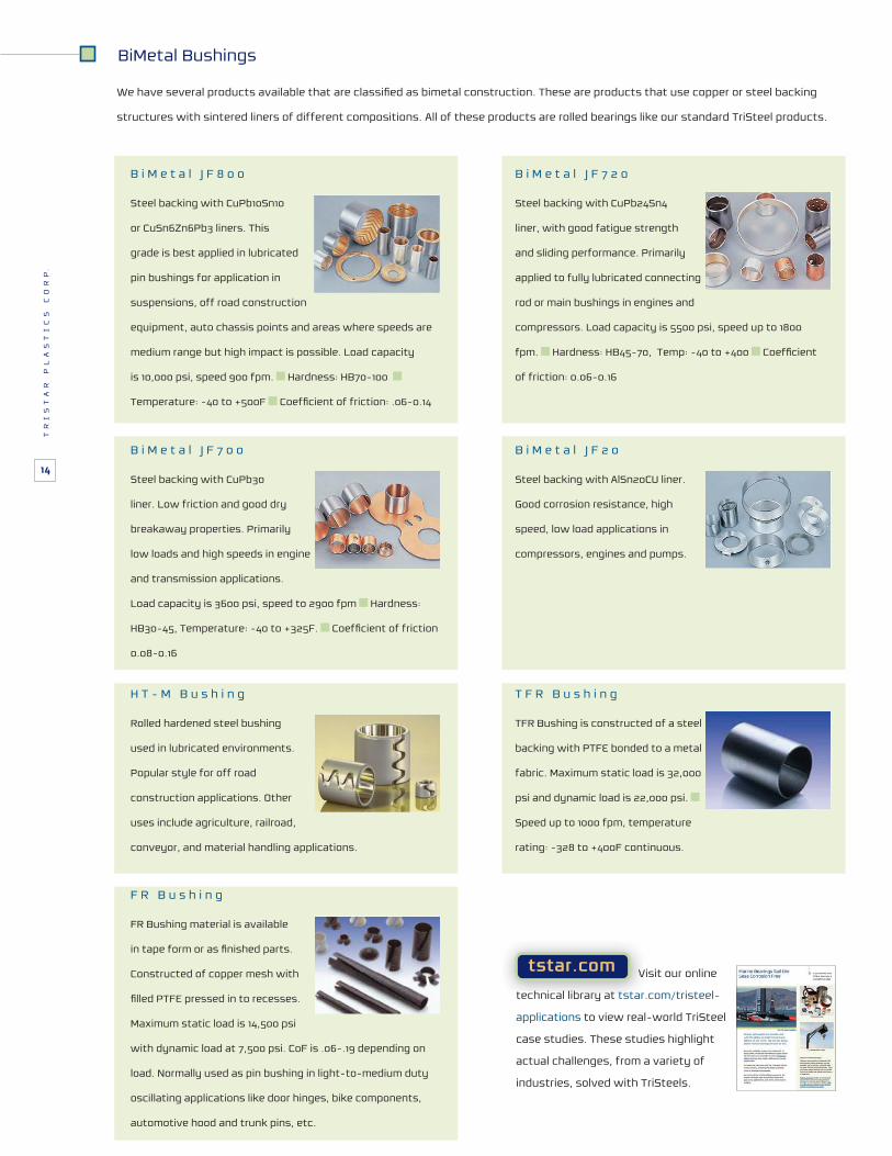
B i M e t a l J F 8 0 0
Steel backing with CuPb10Sn10
or CuSn6Zn6Pb3 liners. This
grade is best applied in lubricated
pin bushings for application in
suspensions, off road construction
equipment, auto chassis points and areas where speeds are
medium range but high impact is possible. Load capacity
is 10,000 psi, speed 900 fpm. Hardness: HB70-100
Temperature: -40 to +500F
B i M e t a l J F 7 2 0
Steel backing with CuPb24Sn4
liner, with good fatigue strength
and sliding performance. Primarily
applied to fully lubricated connecting
rod or main bushings in engines and
compressors. Load capacity is 5500 psi, speed up to 1800
fpm. Hardness: HB45-70, Temp: -40 to +400
of friction: 0.06-0.16
BiMetal Bushings
structures with sintered liners of different compositions. All of these products are rolled bearings like our standard TriSteel products.
B i M e t a l J F 7 0 0
Steel backing with CuPb30
liner. Low friction and good dry
breakaway properties. Primarily
low loads and high speeds in engine
and transmission applications.
Load capacity is 3600 psi, speed to 2900 fpm Hardness:
HB30-45, Temperature: -40 to +325F.
0.08-0.16
B i M e t a l J F 2 0
Steel backing with AlSn20CU liner.
Good corrosion resistance, high
speed, low load applications in
compressors, engines and pumps.
H T - M B u s h i n g
Rolled hardened steel bushing
used in lubricated environments.
Popular style for off road
construction applications. Other
uses include agriculture, railroad,
conveyor, and material handling applications.
T F R B u s h i n g
TFR Bushing is constructed of a steel
backing with PTFE bonded to a metal
fabric. Maximum static load is 32,000
psi and dynamic load is 22,000 psi.
Speed up to 1000 fpm, temperature
rating: -328 to +400F continuous.
F R B u s h i n g
FR Bushing material is available
Constructed of copper mesh with
Maximum static load is 14,500 psi
with dynamic load at 7,500 psi. CoF is .06-.19 depending on
load. Normally used as pin bushing in light-to-medium duty
oscillating applications like door hinges, bike components,
automotive hood and trunk pins, etc.
tstar.com Visit our online
technical library at tstar.com/tristeel-
applications to view real-world TriSteel
case studies. These studies highlight
actual challenges, from a variety of
industries, solved with TriSteels.
TR
IS
TA
R
PL
AS
TI
CS
C
OR
P.
14

Exclusive Rulon Partner
TS-T
RI
R
ev. 2
021a
© Copyright TriStar Plastics Corp. Printed in U.S.A.
North Carolina
Massachusetts
Illinois
California


![Morningstar Tristar Manual[1]](https://static.fdocuments.in/doc/165x107/5695d2761a28ab9b029a81ce/morningstar-tristar-manual1.jpg)