Trips and Fault Finding 6-1 Chapter 6 TRIPS ... - SDS Drives · Trips and Fault Finding 6-1 690+...
8
Trips and Fault Finding 6-1 690+ Series AC Drive Chapter 6 T RIPS AND F AULT F INDING Trips The Master drive combines the fault signals from the drives that make up the 690+ K. The trip is indicated on the Keypad (or other suitable PC programming tool). Each individual drive has Troubleshooting LEDs on the Slave Power Board. These indicate which drive has actually tripped, and the combination of illuminated LEDs provides an indication of the cause. What Happens when a Trip Occurs When a trip occurs, the drive’s power stage is immediately disabled causing the motor and load to coast to a stop. The trip is latched until action is taken to reset it. This ensures that trips due to transient conditions are captured and the drive is disabled, even when the original cause of the trip is no longer present Drive Indications If a trip condition is detected the unit displays and performs the following actions. 1. The HEALTH LED flashes indicating a Trip condition has occurred. (Investigate, find and remove the cause of the trip.) 2. The programming block SEQ & REF::SEQUENCING LOGIC::TRIPPED signal is set to TRUE. The DIGITAL OUTPUT 1 (HEALTH) digital output changes between TRUE/FALSE, depending on the output logic. Keypad Indications (when connected) If a trip condition is detected the MMI displays and performs the following actions. 1. The HEALTH LED on the keypad flashes indicating a Trip condition has occurred and a trip message is displayed stating the cause of the trip. 2. The programming block SEQ & REF::SEQUENCING LOGIC::TRIPPED signal is set to TRUE. The DIGITAL OUTPUT 1 (HEALTH) digital output changes between TRUE/FALSE, depending on the output logic. 3. The trip message(s) must be acknowledged by pressing the STOP key. The trip message may be cleared by pressing the E key. Refer to Chapter 5: “The Keypad” - Alert Message Displays. Resetting a Trip Condition All trips must be reset before the drive can be re-enabled. A trip can only be reset once the trip condition is no longer active, i.e. a trip due to a heatsink over-temperature will not reset until the temperature is below the trip level. Note: More than one trip can be active at any time. For example, it is possible for both the HEATSINK and the OVERVOLTAGE trips to be active. Alternatively it is possible for the drive to trip due to an OVERCURRENT error and then for the HEATSINK trip to become active after the drive has stopped (this may occur due to the thermal time constant of the heatsink). Reset the trip(s) using the remote trip reset input, or by pressing the STOP key on the keypad. Success is indicated by the HEALTH LED (on the unit or MMI) ceasing to flash and returning to a healthy “ON” state. The programming block SEQ & REF::SEQUENCING LOGIC::TRIPPED output is reset to FALSE. DEFAULT DEFAULT
Transcript of Trips and Fault Finding 6-1 Chapter 6 TRIPS ... - SDS Drives · Trips and Fault Finding 6-1 690+...
Trips and Fault Finding 6-1
690+ Series AC Drive
Chapter 6 TRIPS AND FAULT FINDING
Trips
The Master drive combines the fault signals from the drives that make up the 690+ K. The trip is
indicated on the Keypad (or other suitable PC programming tool). Each individual drive has
Troubleshooting LEDs on the Slave Power Board. These indicate which drive has actually
tripped, and the combination of illuminated LEDs provides an indication of the cause.
What Happens when a Trip Occurs When a trip occurs, the drive’s power stage is immediately disabled causing the motor and load
to coast to a stop. The trip is latched until action is taken to reset it. This ensures that trips due to
transient conditions are captured and the drive is disabled, even when the original cause of the
trip is no longer present
Drive Indications If a trip condition is detected the unit displays and performs the following actions.
1. The HEALTH LED flashes indicating a Trip condition has occurred. (Investigate, find and
remove the cause of the trip.)
2. The programming block SEQ & REF::SEQUENCING LOGIC::TRIPPED signal is set to
TRUE.
The DIGITAL OUTPUT 1 (HEALTH) digital output changes between TRUE/FALSE,
depending on the output logic.
Keypad Indications (when connected) If a trip condition is detected the MMI displays and performs the following actions.
1. The HEALTH LED on the keypad flashes indicating a Trip condition has occurred and a
trip message is displayed stating the cause of the trip.
2. The programming block SEQ & REF::SEQUENCING LOGIC::TRIPPED signal is set to
TRUE.
The DIGITAL OUTPUT 1 (HEALTH) digital output changes between TRUE/FALSE,
depending on the output logic.
3. The trip message(s) must be acknowledged by pressing the STOP key. The trip message
may be cleared by pressing the E key. Refer to Chapter 5: “The Keypad” - Alert Message
Displays.
Resetting a Trip Condition All trips must be reset before the drive can be re-enabled. A trip can only be reset once the trip
condition is no longer active, i.e. a trip due to a heatsink over-temperature will not reset until the
temperature is below the trip level.
Note: More than one trip can be active at any time. For example, it is possible for both the HEATSINK and the OVERVOLTAGE trips to be active. Alternatively it is possible for the drive to trip due to an OVERCURRENT error and then for the HEATSINK trip to become active after the drive has stopped (this may occur due to the thermal time constant of the heatsink).
Reset the trip(s) using the remote trip reset input, or by pressing the STOP key on the keypad.
Success is indicated by the HEALTH LED (on the unit or MMI) ceasing to flash and returning
to a healthy “ON” state. The programming block SEQ & REF::SEQUENCING
LOGIC::TRIPPED output is reset to FALSE.
DEFAULT
DEFAULT
balramsingh
Typewritten Text
WWW.SDS.LTD.UK | 0117 9381800
balramsingh
Stamp
balramsingh
Stamp
6-2 Trips and Fault Finding
690+ Series AC Drive
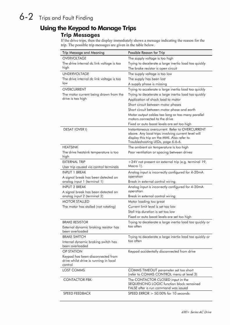
Using the Keypad to Manage Trips Trip Messages If the drive trips, then the display immediately shows a message indicating the reason for the
trip. The possible trip messages are given in the table below.
Trip Message and Meaning Possible Reason for Trip
OVERVOLTAGE
The drive internal dc link voltage is too high
The supply voltage is too high
Trying to decelerate a large inertia load too quickly
The brake resistor is open circuit
UNDERVOLTAGE
The drive internal dc link voltage is too low
The supply voltage is too low
The supply has been lost
A supply phase is missing
OVERCURRENT
The motor current being drawn from the drive is too high
Trying to accelerate a large inertia load too quickly
Trying to decelerate a large inertia load too quickly
Application of shock load to motor
Short circuit between motor phases
Short circuit between motor phase and earth
Motor output cables too long or too many parallel motors connected to the drive
Fixed or auto boost levels are set too high
DESAT (OVER I)
Instantaneous overcurrent. Refer to OVERCURRENT above. Any local trips involving current level will display this trip on the MMI. Also refer to Troubleshooting LEDs, page 6-6-6.
HEATSINK
The drive heatsink temperature is too high
The ambient air temperature is too high
Poor ventilation or spacing between drives
EXTERNAL TRIP
User trip caused via control terminals
+24V not present on external trip (e.g. terminal 19, Macro 1).
INPUT 1 BREAK
A signal break has been detected on analog input 1 (terminal 1)
Analog input is incorrectly configured for 4-20mA operation
Break in external control wiring
INPUT 2 BREAK
A signal break has been detected on analog input 2 (terminal 2)
Analog input is incorrectly configured for 4-20mA operation
Break in external control wiring
MOTOR STALLED
The motor has stalled (not rotating)
Motor loading too great
Current limit level is set too low
Stall trip duration is set too low
Fixed or auto boost levels are set too high
BRAKE RESISTOR
External dynamic braking resistor has been overloaded
Trying to decelerate a large inertia load too quickly or too often
BRAKE SWITCH
Internal dynamic braking switch has been overloaded
Trying to decelerate a large inertia load too quickly or too often
OP STATION
Keypad has been disconnected from drive whilst drive is running in local control
Keypad accidentally disconnected from drive
LOST COMMS COMMS TIMEOUT parameter set too short (refer to COMMS CONTROL menu at level 3)
CONTACTOR FBK
The CONTACTOR CLOSED input in the SEQUENCING LOGIC function block remained FALSE after a run command was issued
SPEED FEEDBACK
SPEED ERROR > 50.00% for 10 seconds
balramsingh
Typewritten Text
WWW.SDS.LTD.UK | 0117 9381800

Trips and Fault Finding 6-3
690+ Series AC Drive
Trip Message and Meaning Possible Reason for Trip
AMBIENT TEMP
The ambient temperature in the drive is too high
MOTOR OVERTEMP
The motor temperature is too high
Excessive load
Motor voltage rating incorrect
FIXED BOOST and/or AUTO BOOST set too high
Prolonged operation of the motor at low speed without forced cooling
Check setting of INVERT THERMIST parameter in I/O TRIPS menu at level 3.
Break in motor thermistor connection
CURRENT LIMIT
If the current exceeds 180% of stack rated current for a period of 1 second, the drive will trip. This is caused by shock loads
Remove the cause of the shock load
SHORT CIRCUIT
The output is short circuited
24V FAILURE
The 24V customer output has fallen below 17V
24V customer output is short circuited
Excessive loading
LOW SPEED OVER I
The motor is drawing too much current (>100%) at zero output frequency
FIXED BOOST and/or AUTO BOOST set too high (refer to FLUXING menu at level 4)
TRIP 22 Reserved
ENCODER 1 FAULT
The Error input on the Encoder TB is in the Error state
VDC RIPPLE
The dc link ripple voltage is too high. Check for a missing input phase.
BRAKE SHORT CCT
Brake resistor overcurrent
Check resistance brake resistor value is greater than minimum allowed
OVERSPEED
Speed feedback > 150% for 0.1 seconds
UNKNOWN
An unknown trip - refer to Parker SSD Drives
MAX SPEED LOW
During Autotune the motor is required to run at the nameplate speed o f the motor. If MAX SPEED RPM limits the speed to less than this value, an error will be reported. Increase the value of MAX SPEED RPM up to the nameplate rpm of the motor (as a minimum). It may be reduced, if required, after the Autotune is complete.
MAINS VOLTS LOW
The mains input voltage is not sufficient to carry out the Autotune. Re-try when the mains has recovered.
NOT AT SPEED
The motor was unable to reach the required speed to carry out the Autotune. Possible reasons include:
motor shaft not free to turn
the motor data is incorrect
MAG CURRENT FAIL
It was not possible to find a suitable value of magnetising current to achieve the required operating condition for the motor. Check the motor data is correct, especially nameplate rpm and motor volts. Also check that the motor is correctly rated for the drive.
balramsingh
Typewritten Text
WWW.SDS.LTD.UK | 0117 9381800
6-4 Trips and Fault Finding
690+ Series AC Drive
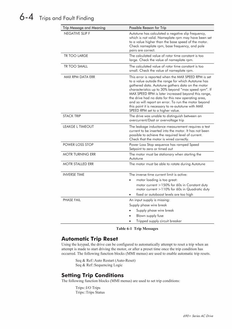
Trip Message and Meaning Possible Reason for Trip
NEGATIVE SLIP F
Autotune has calculated a negative slip frequency, which is not valid. Nameplate rpm may have been set to a value higher than the base speed of the motor. Check nameplate rpm, base frequency, and pole pairs are correct.
TR TOO LARGE
The calculated value of rotor time constant is too large. Check the value of nameplate rpm.
TR TOO SMALL
The calculated value of rotor time constant is too small. Check the value of nameplate rpm.
MAX RPM DATA ERR
This error is reported when the MAX SPEED RPM is set to a value outside the range for which Autotune has gathered data. Autotune gathers data on the motor characteristics up to 30% beyond “max speed rpm”. If MAX SPEED RPM is later increased beyond this range, the drive had no data for this new operating area, and so will report an error. To run the motor beyond this point it is necessary to re-autotune with MAX SPEED RPM set to a higher value.
STACK TRIP
The drive was unable to distinguish between an overcurrent/Dsat or overvoltage trip
LEAKGE L TIMEOUT
The leakage inductance measurement requires a test current to be inserted into the motor. It has not been possible to achieve the required level of current. Check that the motor is wired correctly.
POWER LOSS STOP Power Loss Stop sequence has ramped Speed Setpoint to zero or timed out
MOTR TURNING ERR The motor must be stationary when starting the Autotune
MOTR STALLED ERR
The motor must be able to rotate during Autotune
INVERSE TIME The inverse time current limit is active:
motor loading is too great:
motor current >150% for 60s in Constant duty motor current >110% for 60s in Quadratic duty
fixed or autoboost levels are too high
PHASE FAIL An input supply is missing:
Supply phase wire break
Supply phase wire break
Blown supply fuse
Tripped supply circuit breaker
Table 6-1 Trip Messages
Automatic Trip Reset Using the keypad, the drive can be configured to automatically attempt to reset a trip when an
attempt is made to start driving the motor, or after a preset time once the trip condition has
occurred. The following function blocks (MMI menus) are used to enable automatic trip resets.
Seq & Ref::Auto Restart (Auto-Reset)
Seq & Ref::Sequencing Logic
Setting Trip Conditions The following function blocks (MMI menus) are used to set trip conditions:
Trips::I/O Trips
Trips::Trips Status
balramsingh
Typewritten Text
WWW.SDS.LTD.UK | 0117 9381800
Trips and Fault Finding 6-5
690+ Series AC Drive
Viewing Trip Conditions The following function blocks (MMI menus) can be viewed to investigate trip conditions:
Seq & Ref::Sequencing Logic
Trips::Trips History
Trips::Trips Status
Checksum Fail When the drive powers-up, non-volatile memory is checked to ensure that it has not been
corrupted. In the rare event of corruption being detected, the drive will not function. This may
occur when replacing the control board with an unprogrammed control board.
Drive Indications The failure is indicated by the HEALTH and RUN LEDs showing SHORT FLASH, .
Referring to Chapter 4: “Operating the Drive” - Reading the Status LEDs, you will note that this
also indicates Re-configuration mode, but this mode (and hence the indication) is not available
to the drive unless controlled by an MMI or Comms link.
Because you are controlling the drive locally (no MMI or Comms link etc.), the unit must be
returned to Parker SSD Drives for reprogramming, refer to Chapter 7: “Routine Maintenance
and Repair”. However, if you have access to a keypad or suitable PC programming tool, the unit
can be reset.
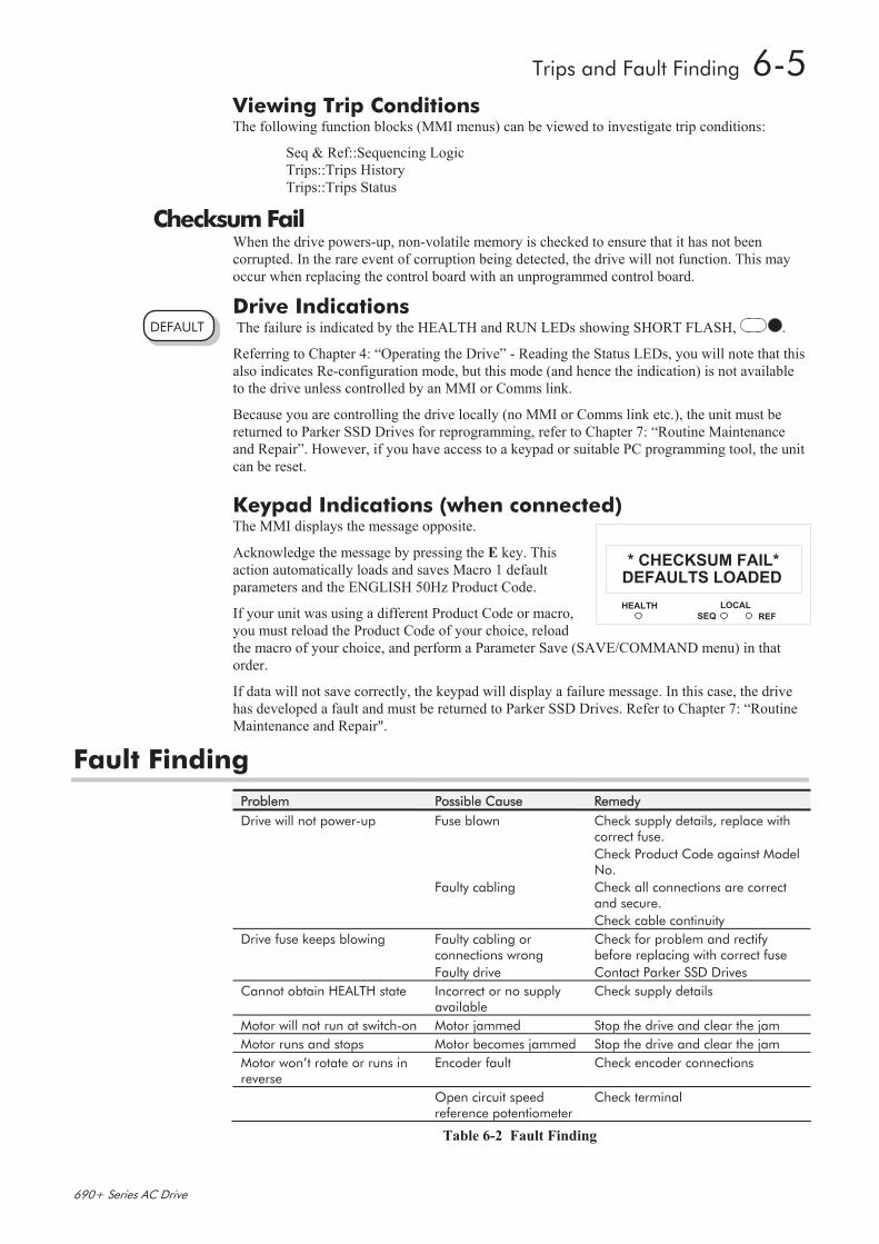
Keypad Indications (when connected) The MMI displays the message opposite.
Acknowledge the message by pressing the E key. This
action automatically loads and saves Macro 1 default
parameters and the ENGLISH 50Hz Product Code.
If your unit was using a different Product Code or macro,
you must reload the Product Code of your choice, reload
the macro of your choice, and perform a Parameter Save (SAVE/COMMAND menu) in that
order.
If data will not save correctly, the keypad will display a failure message. In this case, the drive
has developed a fault and must be returned to Parker SSD Drives. Refer to Chapter 7: “Routine
Maintenance and Repair".
Fault Finding
Problem Possible Cause Remedy
Drive will not power-up Fuse blown Check supply details, replace with correct fuse.
Check Product Code against Model No.
Faulty cabling Check all connections are correct and secure.
Check cable continuity
Drive fuse keeps blowing Faulty cabling or connections wrong
Check for problem and rectify before replacing with correct fuse
Faulty drive Contact Parker SSD Drives
Cannot obtain HEALTH state Incorrect or no supply available
Check supply details
Motor will not run at switch-on Motor jammed Stop the drive and clear the jam
Motor runs and stops Motor becomes jammed Stop the drive and clear the jam
Motor won’t rotate or runs in reverse
Encoder fault Check encoder connections
Open circuit speed reference potentiometer
Check terminal
Table 6-2 Fault Finding
HEALTH LOCAL
SEQ REF
1
1DEFAULTS LOADED
* CHECKSUM FAIL*
DEFAULT
balramsingh
Typewritten Text
WWW.SDS.LTD.UK | 0117 9381800
6-6 Trips and Fault Finding
690+ Series AC Drive
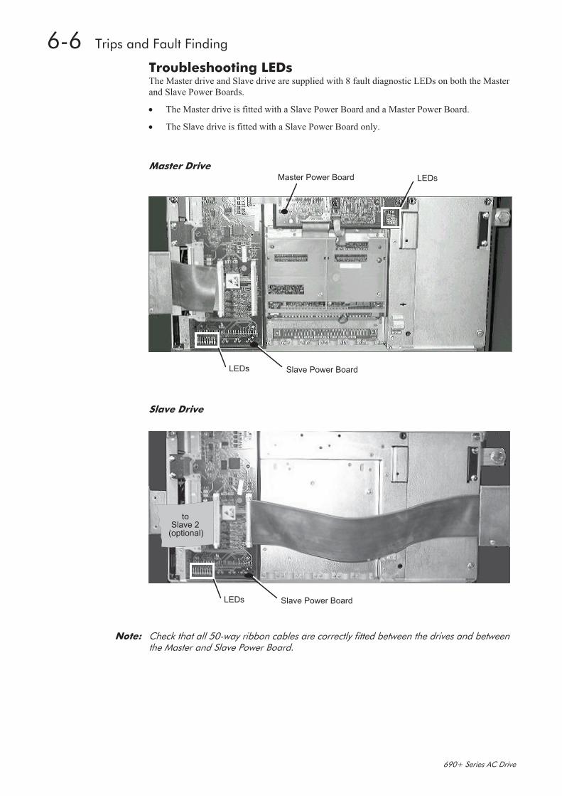
Troubleshooting LEDs The Master drive and Slave drive are supplied with 8 fault diagnostic LEDs on both the Master
and Slave Power Boards.
The Master drive is fitted with a Slave Power Board and a Master Power Board.
The Slave drive is fitted with a Slave Power Board only.
Master Drive LEDsMaster Power Board
Slave Power BoardLEDs
Slave Drive
Slave Power BoardLEDs
toSlave 2
(optional)
Note: Check that all 50-way ribbon cables are correctly fitted between the drives and between the Master and Slave Power Board.
balramsingh
Typewritten Text
WWW.SDS.LTD.UK | 0117 9381800
Trips and Fault Finding 6-7
690+ Series AC Drive
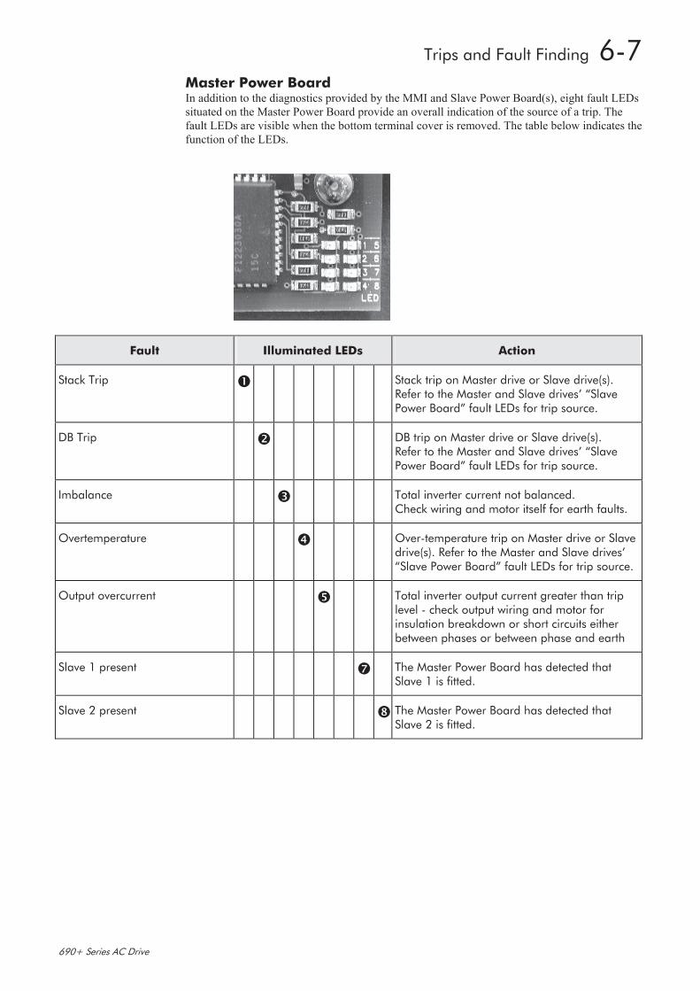
Master Power Board In addition to the diagnostics provided by the MMI and Slave Power Board(s), eight fault LEDs
situated on the Master Power Board provide an overall indication of the source of a trip. The
fault LEDs are visible when the bottom terminal cover is removed. The table below indicates the
function of the LEDs.
Fault Illuminated LEDs Action
Stack Trip Stack trip on Master drive or Slave drive(s). Refer to the Master and Slave drives’ “Slave Power Board” fault LEDs for trip source.
DB Trip DB trip on Master drive or Slave drive(s). Refer to the Master and Slave drives’ “Slave Power Board” fault LEDs for trip source.
Imbalance Total inverter current not balanced. Check wiring and motor itself for earth faults.
Overtemperature Over-temperature trip on Master drive or Slave drive(s). Refer to the Master and Slave drives’ “Slave Power Board” fault LEDs for trip source.
Output overcurrent Total inverter output current greater than trip level - check output wiring and motor for insulation breakdown or short circuits either between phases or between phase and earth
Slave 1 present The Master Power Board has detected that Slave 1 is fitted.
Slave 2 present The Master Power Board has detected that Slave 2 is fitted.
balramsingh
Typewritten Text
WWW.SDS.LTD.UK | 0117 9381800

6-8 Trips and Fault Finding
690+ Series AC Drive
Slave Power Board In addition to the diagnostics provided by the MMI and the Master Power Board, eight fault
LEDs situated on the Slave Power Board provide an indication of the cause of a trip. The fault
LEDs are visible when the bottom terminal cover is removed. The table below indicates the
function of the LEDs.
Slave Faults Illuminated LEDs Action
Output overcurrent Output current greater than trip level - check ouput wiring and motor for insulation breakdown or short circuits either between phases or between phase and earth
Missing ribbon Check that all ribbon cables are correctly fitted between the Slave drives, and between the Master and Slave power board
Overvoltage Excessive DC link voltage. Check that DC link fuses between the drives are not blown.
Phase loss Check that the drives’ three phase supply is present.
M1 phase IGBT fault alarm
M2 phase IGBT fault alarm
M3 phase IGBT fault alarm
Excessive IGBT current - check ouput wiring and motor for insulation breakdown or short circuits either between phases or between phase and earth
DB unit IGBT fault alarm Check dynamic brake resistor wiring and verify value of brake resistor
M1 phase IGBT over-temperature
M2 phase IGBT over-temperature
M3 phase IGBT over-temperature
DB unit IGBT over-temperature
Maximum IGBT junction temperature exceeded
Check operation of main cooling fan and supply
Check that cooling path is free from obstruction
Clean or replace cubicle inlet air filters
Output current imbalance Check wiring to motor and motor itself for earth faults
CAL board not fitted Internal fault - consult supplier
Internal supply fail Internal fault - consult supplier
FPGA not programmed Internal fault - consult supplier
balramsingh
Typewritten Text
WWW.SDS.LTD.UK | 0117 9381800