Trimble R9s Receiver - Доставка по России ... · Trimble R9s Receiver 1. ......
45
Version 5.12 Revision A March 2016 GETTING STARTED GUIDE Trimble R9s Receiver 1
Transcript of Trimble R9s Receiver - Доставка по России ... · Trimble R9s Receiver 1. ......
Version 5.12Revision AMarch 2016
GETTING STARTED GUIDE
Trimble R9s Receiver
1
Corporate OfficeTrimble Navigation Limited935 Stewart DriveSunnyvale, California 94085USA
Geospatial DivisionTrimble Navigation Limited10368 Westmoor DriveWestminster, CO 80021USAwww.trimble.comEmail: [email protected]
Legal Notices© 2016, Trimble Navigation Limited. All rights reserved.Trimble, the Globe & Triangle logo are trademarks of Trimble Navigation Limited, registered in the United States and in other countries. CMR+, and Zephyr are trademarks of Trimble Navigation Limited. The Bluetooth word mark and logos are owned by the Bluetooth SIG, Inc. and any use of such marks by Trimble Navigation Limited is under license.
NTP Software Copyright© David L. Mills 1992-2009. Permission to use, copy, modify, and distribute this software and its documentation for any purpose with or without fee is hereby granted, provided that the above copyright notice appears in all copies and that both the copyright notice and this permission notice appear in supporting documentation, and that the name University of Delaware not be used in advertising or publicity pertaining to distribution of the software without specific, written prior permission. The University of Delaware makes no representations about the suitability this software for any purpose. It is provided "as is" without express or implied warranty.
Release NoticeThis is the March 2016 release (Revision A) of the Trimble R9s receiver documentation.
Product Limited Warranty InformationFor applicable product Limited Warranty information, please refer to the Limited Warranty Card included with this Trimble product, or consult your local Trimble authorized dealer
COCOM limitsThis notice applies to the R9s receiver.The U.S. Department of Commerce requires that all exportable GPS products contain performance limitations so that they cannot be used in a manner that could threaten the security of the United States. The following limitations are implemented on this product:– Immediate access to satellite measurements and navigation results is disabled when the receiver velocity is computed to be greater than 1,000 knots, or its altitude is computed to be above 18,000 meters. The receiver GPS subsystem resets until the COCOM situation clears. As a result, all logging and stream configurations stop until the GPS subsystem is cleared.
NoticesClass B Statement – Notice to Users. This equipment has been tested and found to comply with the limits for a Class B digital device pursuant to Part 15 of the FCC Rules. Some equipment configurations include an optional 410 MHz to 470 MHz UHF radio transceiver module compliant with Part 90. These limits are designed to provide reasonable protection against harmful interference in a residential installation. This equipment generates, uses, and can radiate radio frequency energy and, if not installed and used in accordance with the instructions, may cause harmful interference to radio communication. However, there is no guarantee that interference will not occur in a particular installation. If this equipment does cause harmful interference to radio or television reception, which can be determined by turning the equipment off and on, the user is encouraged to try to correct the interference by one or more of the following measures:– Increase the separation between the equipment and the receiver.– Connect the equipment into an outlet on a circuit different from that to which the receiver is connected.– Consult the dealer or an experienced radio/TV technician for help.
Changes and modifications not expressly approved by the manufacturer or registrant of this equipment can void your authority to operate this equipment under Federal Communications Commission rules.This equipment must be installed and operated in accordance with provided instructions and the antenna(s) used for this transmitter must be installed to provide a separation distance of at least 20 cm from all persons and must not be co-located or operated in conjunction with any other antenna or transmitters (except in accordance with the FCC multi -transmitter product procedures)The Federal Communications Commission (FCC, USA) has dictated that on 1 January 2013, all radio users transmitting data between 421 and 512 MHz within the United States of America, must operate within 12.5 kHz channels or transmit using the bits per second (bps) settings of 19200 bps when using a 25 kHz channel. For more information on the FCC mandate, please view http://trl.trimble.com/docushare/dsweb/Get/Document-618141/Survey_CustomerFAQs_FCencryption or search the Internet.
CanadaThis Class B digital apparatus complies with Canadian ICES-003.Cet appareil numérique de la classe B est conforme à la norme NMB-003 du Canada.This apparatus complies with Canadian RSS-GEN, RSS-310, RSS-210, and RSS-119.Cet appareil est conforme à la norme CNR-GEN, CNR-310, CNR-210, et CNR-119 du Canada.
Europee products covered by this guide may be operated in all EU member countries (BE, BG, CZ, DK, DE, EE, IE, EL, ES, FR, HR, IT, CY, LV, LT, LU, HU, MT, NL, AT, PL, PT, RO, SI, SK, FI, SE, UK), Norway and Switzerland. Products been tested and found to comply with the requirements for a Class B device pursuant to European Council Directive 89/336/EEC on EMC, thereby satisfying the requirements for CE Marking and sale within the European Economic Area (EEA). Contains a Bluetooth radio module. These requirements are designed to provide reasonable protection against harmful interference when the equipment is operated in a residential or commercial environment. The 450 MHZ (PMR) bands and 2.4 GHz are non-harmonized throughout Europe.
CE Declaration of ConformityHereby, Trimble Navigation, declares that the GPS receivers are in compliance with the essential requirements and other relevant provisions of Directive 1999/5/EC.
Australia and New ZealandThis product conforms with the regulatory requirements of the Australian Communications and Media Authority (ACMA) EMC framework, thus satisfying the requirements for RCM marking and sale within Australia and New Zealand.
Restriction of Use of Certain Hazardous Substances in Electrical
and Electronic Equipment (RoHS)Trimble products in this guide comply in all material respects with DIRECTIVE 2002/95/EC OF THE EUROPEAN PARLIAMENT AND OF THE COUNCIL of 27 January 2003 on the restriction of the use of certain hazardous substances in electrical and electronic equipment (RoHS Directive) and Amendment 2005/618/EC filed under C(2005) 3143, with exemptions for lead in solder pursuant to Paragraph 7 of the Annex to the RoHS Directive applied.
Waste Electrical and Electronic Equipment (WEEE)For product recycling instructions and more information, please go to www.trimble.com/ev.shtml. Recycling in Europe: To recycle Trimble WEEE (Waste Electrical and Electronic Equipment, products that run on electrical power.), Call +31 497 53 24 30, and ask for the “WEEE Associate”. Or, mail a request for recycling instructions to:Trimble Europe BVc/o Menlo Worldwide LogisticsMeerheide 455521 DZ Eersel, NL
Trimble R9s Receiver Getting Started Guide 2
FCC Declaration of Conformity
We, Trimble Navigation Limited.
935 Stewart DrivePO Box 3642Sunnyvale, CA 94088-3642United States+1-408-481-8000
Declare under sole responsibility that DoC products comply with Part 15 of FCC Rules.
Operation is subject to the following two conditions:(1) This device may not cause harmful interference, and(2) This device must accept any interference received, including interference that may cause undesired operation
Unlicensed radios in productsThis device complies with part 15 of the FCC Rules.Operation is subject to the following two conditions:(1) This device may not cause harmful interference, and(2) This device must accept any interference received, including interference that may cause undesired operation.
Licensed radios in productsThis device complies with part 15 of the FCC Rules.Operation is subject to the condition that this device may not cause harmful interference.
RTTE Compliance statements
Czech Trimble Navigation Limited tímto prohlašuje, že tento (R9s přijímač) je ve shodě se základními požadavky a dalšími příslušnými ustanoveními směrnice 1999/5/ES.
Danish Undertegnede Trimble Navigation Limited erklærer herved, at følgende udstyr (R9s přijímač) overholder de væsentlige krav og øvrige relevante krav i direktiv 1999/5/EF.
Dutch Hierbij verklaart Trimble Navigation Limited dat het toestel (R9s přijímač) in overeenstemming is met de essentiële eisen en de andere relevante bepalingen van richtlijn 1999/5/EG.
English Hereby, Trimble Navigation Limited, declares that this equipment (R9s přijímač) is in compliance with the essential requirements and other relevant provisions of Directive 1999/5/EC.
Estonian Käesolevaga kinnitab Trimble Navigation Limited seadme (R9s přijímač) vastavust direktiivi 1999/5/EÜ põhinõuetele ja nimetatud direktiivist tulenevatele teistele asjakohastele sätetele.
German Hiermit erklärt Trimble Navigation Limited, dass sich das Gerät (R9s přijímač) in Übereinstimmung mit den grundlegenden Anforderungen und den übrigen einschlägigen Bestimmungen der Richtlinie 1999/5/EG befindet.
Greek ΜΕ ΤΗΝ ΠΑΡΟΥΣΑ Trimble Navigation Limited ΔΗΛΩΝΕΙ ΟΤΙ (R9s přijímač) ΣΥΜΜΟΡΦΩΝΕΤΑΙ ΠΡΟΣ ΤΙΣ ΟΥΣΙΩΔΕΙΣ ΑΠΑΙΤΗΣΕΙΣ ΚΑΙ ΤΙΣ ΛΟΙΠΕΣ ΣΧΕΤΙΚΕΣ ΔΙΑΤΑΞΕΙΣ ΤΗΣ ΟΔΗΓΙΑΣ 1999/5/ΕΚ.
Hungarian Alulírott, Trimble Navigation Limited nyilatkozom, hogy a (R9s přijímač) megfelel a vonatkozó alapvetõ követelményeknek és az 1999/5/EC irányelv egyéb elõírásainak.
Finnish Trimble Navigation Limited vakuuttaa täten että (R9s přijímač) tyyppinen laite on direktiivin 1999/5/EY oleellisten vaatimusten ja sitä koskevien direktiivin muiden ehtojen mukainen.
French Par la présente Trimble Navigation Limited déclare que l'appareil (R9s přijímač) est conforme aux exigences essentielles et aux autres dispositions pertinentes de la directive 1999/5/CE.
Icelandic Hér með lýsir Trimble Navigation Limited yfir því að (R9s přijímač) er í samræmi við grunnkröfur og aðrar kröfur, sem gerðar eru í tilskipun 1999/5/EC.
Italian Con la presente Trimble Navigation Limited dichiara che questo (R9s přijímač) è conforme ai requisiti essenziali ed alle altre disposizioni pertinenti stabilite dalla direttiva 1999/5/CE.
Latvian Ar šo Trimble Navigation Limited deklarē, ka (R9s přijímač) atbilst Direktīvas 1999/5/EK būtiskajām prasībām un citiem ar to saistītajiem noteikumiem.
Lithuanian Šiuo Trimble Navigation Limited deklaruoja, kad šis (R9s přijímač) atitinka esminius reikalavimus ir kitas 1999/5/EB Direktyvos nuostatas.
Maltese Hawnhekk, Trimble Navigation Limited, jiddikjara li dan (R9s přijímač) jikkonforma mal-ħtiġijiet essenzjali u ma provvedimenti oħrajn relevanti li hemm fid-Dirrettiva 1999/5/EC.
Norwegian Trimble Navigation Limited erklærer herved at utstyret (R9s přijímač) i samsvar med de grunnleggende krav og øvrige relevante krav i direktiv 1999/5/EF.
Polish Niniejszym Trimble Navigation Limited oświadcza, że (R9s přijímač) jest zgodny z zasadniczymi wymogami oraz pozostałymi stosownymi postanowieniami Dyrektywy 1999/5/EC.
Portuguese Trimble Navigation Limited declara que este (R9s přijímač) está conforme com os requisitos essenciais e outras disposições da Directiva 1999/5/CE.
Slovak Trimble Navigation Limited týmto vyhlasuje, že (R9s přijímač) spĺňa základné požiadavky a všetky príslušné ustanovenia Smernice 1999/5/ES.
Slovenian Trimble Navigation Limited izjavlja, da je ta (R9s přijímač) skladu z bistvenimi zahtevami in ostalimi relevantnimi določili direktive 1999/5/ES.
Spanish Por medio de la presente Trimble Navigation Limited declara que el (R9s přijímač) cumple con los requisitos esenciales y cualesquiera otras disposiciones aplicables o exigibles de la Directiva 1999/5/CE.
Swedish Härmed intygar Trimble Navigation Limited att denna (R9s přijímač) står I överensstämmelse med de väsentliga egenskapskrav och övriga relevanta bestämmelser som framgår av direktiv 1999/5/EG.
Trimble R9s Receiver Getting Started Guide 3
Safety InformationBefore you use your Trimble product, make sure that you have read and understood all safety requirements.
WARNING – This alert warns of a potential hazard which, if not avoided, could result in severe injury or even death.
CAUTION – This alert warns of a potential hazard or unsafe practice that could result in minor injury or property damage or irretrievable data loss.
Note – An absence of specific alerts does not mean that there are no safety risks involved.
Regulations and safetySome receiver models with base station capability contain an internal radio-modem for transmission or can transmit through an external data communications radio. Regulations regarding the use of the 410 MHz to 470 MHz radio-modems vary greatly from country to country. In some countries, the unit can be used without obtaining an end-user license. Other countries require end-user licensing. For licensing information, consult your local Trimble dealer.
All Trimble receiver models described in this documentation are capable of transmitting data through Bluetooth wireless technology.
Bluetooth wireless technology operates in license-free bands.
Before operating a Trimble receiver or GSM modem, determine if authorization or a license to operate the unit is required in your country. It is the responsibility of the end user to obtain an operator's permit or license for the receiver for the location or country of use.
For FCC regulations, see Notices.
Use and CareThis product is designed to withstand the rough treatment and tough environment that typically occurs in construction applications. However, the receiver is a high-precision electronic instrument and should be treated with reasonable care.
CAUTION – Operating or storing the receiver outside the specified temperature range can damage it.
Type approvalType approval, or acceptance, covers technical parameters of the equipment related to emissions that can cause interference. Type approval is granted to the manufacturer of the transmission
Trimble R9s Receiver Getting Started Guide 4
equipment, independent from the operation or licensing of the units. Some countries have unique technical requirements for operation in particular radio-modem frequency bands. To comply with those requirements, Trimble may have modified your equipment to be granted type approval.
Unauthorized modification of the units voids the type approval, the warranty, and the operational license of the equipment.
Exposure to radio frequency radiation
For 450 MHz radioSafety. Exposure to RF energy is an important safety consideration. The FCC has adopted a safety standard for human exposure to radio frequency electromagnetic energy emitted by FCC regulated equipment as a result of its actions in General Docket 79-144 on March 13, 1986.
Proper use of this radio modem results in exposure below government limits. The following precautions are recommended:
l DO NOT operate the transmitter when someone is within 20 cm (7.8 inches) of the antenna.
l DO NOT co-locate (place within 20 cm (7.8 inches)) the radio antenna with any other transmitting antenna.
l DO NOT operate the transmitter unless all RF connectors are secure and any open connectors are properly terminated.
l DO NOT operate the equipment near electrical blasting caps or in an explosive atmosphere.
l All equipment must be properly grounded according to Trimble installation instructions for safe operation.
l All equipment should be serviced only by a qualified technician.
For GSM/GPRS radioSafety. Exposure to RF energy is an important safety consideration. The FCC has adopted a safety standard for human exposure to radio frequency electromagnetic energy emitted by FCC regulated equipment as a result of its actions in General Docket 79-144 on March 13, 1986.
Proper use of this radio modem results in exposure below government limits. The following precautions are recommended:
l DO NOT operate the transmitter when someone is within 28 cm (11 inches) of the antenna.
l All equipment should be serviced only by a qualified technician.
For Bluetooth radioThe radiated output power of the internal Bluetooth wireless radio and the Wi-Fi radio included in some Trimble receivers is far below the FCC radio frequency exposure limits. Nevertheless, the wireless radio(s) shall be used in such a manner that the Trimble receiver is 20 cm or further from the human body. The internal wireless radio(s) operate within guidelines found in radio frequency safety standards and recommendations, which reflect the consensus of the scientific community. Trimble therefore believes that the internal wireless radio(s) are safe for use by consumers. The level of
Trimble R9s Receiver Getting Started Guide 5

energy emitted is far less than the electromagnetic energy emitted by wireless devices such as mobile phones. However, the use of wireless radios may be restricted in some situations or environments, such as on aircraft. If you are unsure of restrictions, you are encouraged to ask for authorization before turning on the wireless radio.
Installing antennasCAUTION – For your own safety, and in terms of the RF exposure requirements of the FCC, always observe these precautions:
– Always maintain a minimum separation distance of 20 cm (7.8 inches) between yourself and the radiating antenna.– Do not co-locate the antenna with any other transmitting device.
WARNING – The GNSS antenna and its cabling should be installed in accordance with all national and local electrical codes, regulations, and practices. The antenna and cabling should be installed where they will not
become energized as a result of falling nearby power lines, nor be mounted where they are subjected to over-voltage transients, particularly lightning. Such installations require additional protective means that are detailed in national and local electrical codes.
WARNING – If a Trimble antenna is powered from an external source rather than the GNSS receiver as recommended, that source must be a Limited Power Source (LPS) as defined in IEC 60950-1.
Trimble receiver internal radios have been designed to operate with the antennas listed below. Antennas not included in this list, or that have a gain greater than 5 dBi are strictly prohibited for use with this device. The required antenna impedance is 50 ohms.
To reduce potential radio interference to other users, the antenna type and its gain should be so chosen so that the equivalent isotropically radiated power (e.i.r.p.) is not more than that permitted for successful communication.
Lithium-ion Battery safetyWARNING – Do not damage the rechargeable Lithium-ion battery. A damaged battery can cause an explosion or fire, and can result in personal injury and/or property damage.
To prevent injury or damage:– Do not use or charge the battery if it appears to be damaged. Signs of damage include, but are not limited to, discoloration, warping, and leaking battery fluid.– Do not expose the battery to fire, high temperature, or direct sunlight.– Do not immerse the battery in water.– Do not use or store the battery inside a vehicle during hot weather.– Do not drop or puncture the battery.– Do not open the battery or short-circuit its contacts.
Trimble R9s Receiver Getting Started Guide 6
WARNING – Avoid contact with the rechargeable Lithium-ion battery if it appears to be leaking. Battery fluid is corrosive, and contact with it can result in personal injury and/or property damage.
To prevent injury or damage:– If the battery leaks, avoid contact with the battery fluid.– If battery fluid gets into your eyes, immediately rinse your eyes with clean water and seek medical attention. Do not rub your eyes!– If battery fluid gets onto your skin or clothing, immediately use clean water to wash off the battery fluid.
WARNING – Charge and use the rechargeable Lithium-ion battery only in strict accordance with the instructions.
To prevent injury or damage:– Discontinue charging a battery that gives off extreme heat or a burning odor.– Never attempt to remove, replace, or repair the battery yourself.– If the battery requires attention, send the receiver to an authorized Trimble Service Center.
Connecting the receiver to a vehicle battery
WARNING – Use caution when connecting battery cable's clip leads to a vehicle battery. Do not allow any metal object or jewelry to connect (short) the battery's positive (+) terminal to either the negative (-)
terminal or the metal of the vehicle connected to the battery. This could result in high current, arcing, and high temperatures, exposing the user to possible injury.
WARNING – When connecting an external battery, such as a vehicle battery, to the receiver, be sure to use the Trimble cable with proper over-current protection intended for this purpose, to avoid a safety hazard to
the user or damage to the product.
Wet locations
WARNING – This product is not intended to be used outdoors or in a wet location when it is powered by the PoE interface, or by the external power supply. The connection is not waterproof and could be subject to
electrical shorting.
WARNING – The external power adaptor and its associated power cord and plug are not intended to be installed outdoors, or in a wet location.
Trimble R9s Receiver Getting Started Guide 7
Contents
Safety Information 4Regulations and safety 4Use and Care 4Type approval 4Exposure to radio frequency radiation 5Installing antennas 6Lithium-ion Battery safety 6
Contents 8
1 Introduction 9Related information 9Technical support 9
2 Batteries and Power 10Batteries 10External Power 12
3 Front Panel Guide 15Keypad and display 15Button operations 16Power button operations 16Home screen 17R9s mode screens 18
4 Rear Connectors 20
5 Configuring System Settings 22External data logging to an external device 24
6 Signal Tracking 29
7 Managing Application Files 30
8 Default Receiver Settings 32Resetting the receiver to factory defaults 33
9 Adding Radio Frequencies 34Setting UHF reception radio frequencies using the web interface 34
10 Troubleshooting Receiver Issues 35
Glossary 37
Trimble R9s Receiver Getting Started Guide 8
IntroductionThe Trimble R9s receiver is ideal for the following survey applications:
l Base station for precision GNSS applications
l Data collection for Static and Fast Static Surveys
l Precision RTK rover
The receiver has a keypad and display, so you can configure the receiver without using a controller or computer. It can be ordered with a 410 MHz to 470 MHz UHF receive and transmit radio.
The receiver can record GNSS data to the internal memory or an external thumb drive, and transfer the data over a serial or Ethernet connection.
Related informationAn electronic copy of this manual is available in portable document format (PDF) at www.trimble.com. Use Adobe Reader to view the contents of this file.
Sources of related information include the following:
l Release notes – The release notes describe new features of the product, information not included in the manuals, and any changes to the manuals. They can be downloaded from the Trimble website at www.trimble.com/Support/Support_AZ.aspx.
l Trimble training courses – Consider a training course to help you use your GNSS system to its fullest potential. For more information, go to the Trimble website at www.trimble.com/Support/Index_Training.aspx.
l Registration – register your receiver to automatically receive e-mail notifications of receiver firmware upgrades and new functionality. To register, go to www.trimble.com.
Contact your local Trimble distribution partner for more information about the support agreement contracts for software and firmware, and an extended warranty program for hardware.
Technical supportIf you have a problem and cannot find the information you need in the product documentation, contact your local dealer. Alternatively, go to the Support area of the Trimble website (www.trimble.com/Support.shtml). Select the product you need information on. Product updates, documentation, and any support issues are available for download.
Trimble R9s Receiver Getting Started Guide 9
1 Introduction
Batteries and Power
BatteriesThe receiver has one internal rechargeable Lithium-ion battery.
The operational time provided by the internal battery depends on the type of measurement and operating conditions. Typically, the internal battery provides 10 hours operation as a base station and 12 hours as a rover during measurement operations using the internal radio.
The receiver can also be powered by an external power source that is connected to the Lemo or modem port.
All battery operation tests are carried out with new, fully-charged batteries at room temperature and with full receiver configuration operational. Older batteries, at temperatures significantly higher or lower than room temperature, will have a reduced performance. Receivers operating with reduced configuration will have a higher performance.
Battery safetyCharge and use the battery only in strict accordance with the instructions provided.
Internal lithium-ion battery
WARNING – Do not damage the rechargeable Lithium-ion battery. A damaged battery can cause an explosion or fire, and can result in personal injury and/or property damage.
To prevent injury or damage:– Do not use or charge the battery if it appears to be damaged. Signs of damage include, but are not limited to, discoloration, warping, and leaking battery fluid.– Do not expose the battery to fire, high temperature, or direct sunlight.– Do not immerse the battery in water.– Do not use or store the battery inside a vehicle during hot weather.– Do not drop or puncture the battery.– Do not open the battery or short-circuit its contacts.
WARNING – Avoid contact with the rechargeable Lithium-ion battery if it appears to be leaking. Battery fluid is corrosive, and contact with it can result in personal injury and/or property damage.
To prevent injury or damage:– If the battery leaks, avoid contact with the battery fluid.– If battery fluid gets into your eyes, immediately rinse your eyes with clean water and seek medical attention. Do not rub your eyes!– If battery fluid gets onto your skin or clothing, immediately use clean water to wash off the battery fluid.
Trimble R9s Receiver Getting Started Guide 10
2 Batteries and Power

Connecting the receiver to a vehicle battery
WARNING – Use caution when connecting battery cable's clip leads to a vehicle battery. Do not allow any metal object or jewelry to connect (short) the battery's positive (+) terminal to either the negative (-)
terminal or the metal of the vehicle connected to the battery. This could result in high current, arcing, and high temperatures, exposing the user to possible injury.
WARNING – When connecting an external battery, such as a vehicle battery, to the receiver, be sure to use the Trimble cable with proper over-current protection intended for this purpose, to avoid a safety hazard to
the user or damage to the product.
Charging the Lithium-ion batteriesThe rechargeable Lithium-ion batteries are supplied partially charged. Charge the battery completely before using it for the first time. If the battery has been stored for longer than three months, charge it before use.
WARNING – Charge and use the rechargeable Lithium-ion battery only in strict accordance with the instructions.
To prevent injury or damage:– Discontinue charging a battery that gives off extreme heat or a burning odor.– Never attempt to remove, replace, or repair the battery yourself.– If the battery requires attention, send the receiver to an authorized Trimble Service Center.
The internal battery charges fully in 8 hours when connected to a suitable power source.
When the internal temperature of the receiver is greater than 50 °C (122 °F) or less than 5 °C (41 °F), the internal battery charger stops charging and the receiver’s display shows Charger Disabled, Temp Limited. However, the receiver will still draw its power from the external DC source, extending the operating time in the field.
When the external DC voltage is not able to support the power drain, an X is displayed across the battery status icon on the front panel display, which indicates that the internal charger is off.
Using the Lithium-ion battery as a Universal Power Supply (UPS)The internal battery will only charge from an external power source as long as that source can support the power drain, for example, an AC power adaptor. The receiver is supplied with an AC power (also known as mains power) supply unit that recharges the battery inside the receiver when it is connected through the adaptor to the modem port or the Lemo port. When you use the receiver on large projects, from a permanent or semi-permanent base station location in a site trailer, Trimble recommends that you use this power supply at all times to keep the internal battery charged. This provides an uninterrupted power supply and will keep the site operational for more than 10 hours after a power failure.
Trimble R9s Receiver Getting Started Guide 11
2 Batteries and Power
Keep all batteries on continuous charge when not in use. You can keep batteries on charge indefinitely without damage to the receiver or to the batteries.
Removing the rechargeable Lithium-ion batteryThe internal Lithium-ion battery should be removed only at an authorized Trimble Service Center. If the battery is removed at an unauthorized service center, the remaining warranty on the product will be void.
Storing the Lithium-ion batteryIf you must store a Lithium-ion battery for long periods, make sure that it is fully charged before it is stored, and that you charge it at least once every three months while it is stored.
Do not allow a battery that is in storage to discharge to below 5 V. A battery that reaches deep discharge level (5 V or less) cannot be recharged and must be replaced. To protect a battery that is in use from deep discharge, the receiver switches power sources or stops drawing power when the battery pack discharges to 5.9 V.
All batteries discharge over time when not in use, and they discharge faster in colder temperatures. Do not store the receiver at temperatures outside the range –40 °C to +70 °C (–40 °F to +158 °F).
External PowerSources of external power include:
l AC power
l 12 V vehicle battery
l Trimble custom external battery pack
l Generator power
l Solar panel
The receiver uses an external power source in preference to its internal batteries. If the receiver is not connected to an external power source, or if the external power supply fails, the internal batteries are used.
While carrying out static measurements for postprocessed computations using the internal or external memory, if no external power is supplied and the internal battery is drained, the receiver shuts down. No data is lost and when power is restored, the receiver restarts in the same status as it was when power was lost.
It is possible to turn off the internal battery using the web interface. In this case, when external power is switched off, there is a limited time (30 seconds) before the unit turns off.
Trimble R9s Receiver Getting Started Guide 12
2 Batteries and Power

Supported power cables
Part Number
Receiver Connection
Power Connection
Power Source Other Connectors
59044 7-pin Lemo Cable with DC plug
Power to host devices from AC adapter
Serial
59044-10 7-pin Lemo Cable with SAE
Power from SAE connection
Serial
57167-SUR 26-pin Adapter with DC plug
Power from AC adapter USB(B) socket and Ethernet socket
57168-SUR 26-pin Adapter with DC plug
Power from AC adapter Serial and Ethernet socket
58339-SUR 26-pin Adapter with DC plug
Power from AC adapter
USB(A) socket and Ethernet socket
60789-00, 77070-00
26-pin Cable with DC plug
Power from AC adapter 2 x Serial, Ethernet plug, USB(A) plug, 1PPS (BNC)
65791-00, 78235-00
26-pin Cable with DC
Power from AC adapter
2 x Serial, Ethernet socket
78235-10 26-pin Cable with SAE
Power from SAE connection
2 x Serial, Ethernet socket, 1PPS (BNC)
Note – R9s low voltage cut-offs:Power applied through the Lemo connector models a standard 12.4 V lead acid battery. Shut-down voltage is temperature-compensated and is designed to prolong the life of a lead acid battery and not place it into a deep discharge state.Power applied through the 26-pin adaptor cable models a standard 11.1 V lithium-ion battery. Shut-down voltage is temperature-compensated and is designed to prolong the life of a lithium-ion battery.The external DC voltage supply can be used by the receiver if it is in the range stated by the label on the receiver.
Connecting the receiver to a vehicle battery
WARNING – Use caution when connecting battery cable's clip leads to a vehicle battery. Do not allow any metal object or jewelry to connect (short) the battery's positive (+) terminal to either the negative (-)
terminal or the metal of the vehicle connected to the battery. This could result in high current, arcing, and high temperatures, exposing the user to possible injury.
Trimble R9s Receiver Getting Started Guide 13
2 Batteries and Power
WARNING – When connecting an external battery, such as a vehicle battery, to the receiver, be sure to use the Trimble cable with proper over-current protection intended for this purpose, to avoid a safety hazard to
the user or damage to the product.
Trimble R9s Receiver Getting Started Guide 14
2 Batteries and Power
Front Panel Guide
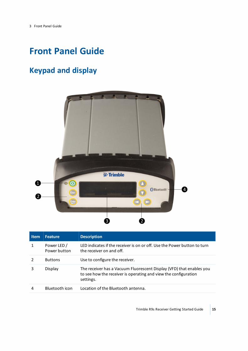
Keypad and display
Item Feature Description
1 Power LED / Power button
LED indicates if the receiver is on or off. Use the Power button to turn the receiver on and off.
2 Buttons Use to configure the receiver.
3 Display The receiver has a Vacuum Fluorescent Display (VFD) that enables you to see how the receiver is operating and view the configuration settings.
4 Bluetooth icon Location of the Bluetooth antenna.
Trimble R9s Receiver Getting Started Guide 15
3 Front Panel Guide
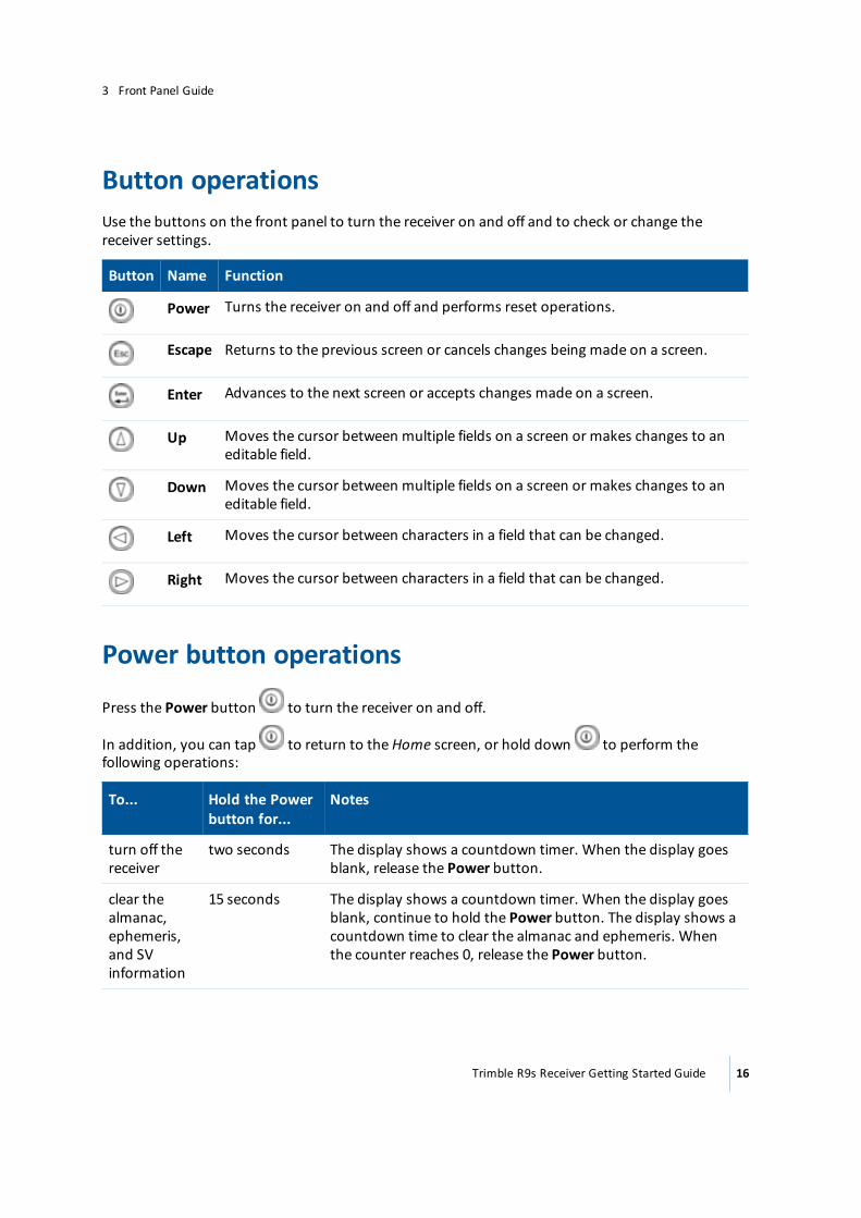
Button operationsUse the buttons on the front panel to turn the receiver on and off and to check or change the receiver settings.
Button Name Function
Power Turns the receiver on and off and performs reset operations.
Escape Returns to the previous screen or cancels changes being made on a screen.
Enter Advances to the next screen or accepts changes made on a screen.
Up Moves the cursor between multiple fields on a screen or makes changes to an editable field.
Down Moves the cursor between multiple fields on a screen or makes changes to an editable field.
Left Moves the cursor between characters in a field that can be changed.
Right Moves the cursor between characters in a field that can be changed.
Power button operations
Press the Power button to turn the receiver on and off.
In addition, you can tap to return to the Home screen, or hold down to perform the following operations:
To... Hold the Power button for...
Notes
turn off the receiver
two seconds The display shows a countdown timer. When the display goes blank, release the Power button.
clear the almanac, ephemeris, and SV information
15 seconds The display shows a countdown timer. When the display goes blank, continue to hold the Power button. The display shows a countdown time to clear the almanac and ephemeris. When the counter reaches 0, release the Power button.
Trimble R9s Receiver Getting Started Guide 16
3 Front Panel Guide
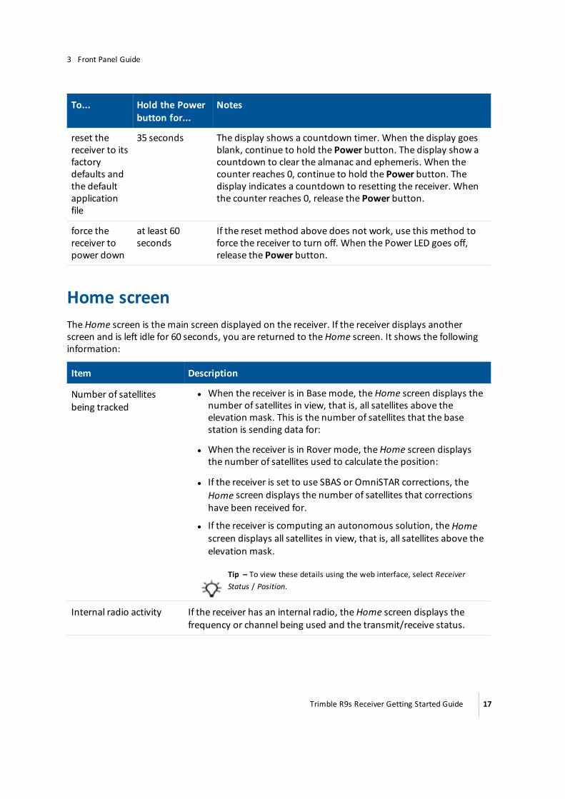
To... Hold the Power button for...
Notes
reset the receiver to its factory defaults and the default application file
35 seconds The display shows a countdown timer. When the display goes blank, continue to hold the Power button. The display show a countdown to clear the almanac and ephemeris. When the counter reaches 0, continue to hold the Power button. The display indicates a countdown to resetting the receiver. When the counter reaches 0, release the Power button.
force the receiver to power down
at least 60 seconds
If the reset method above does not work, use this method to force the receiver to turn off. When the Power LED goes off, release the Power button.
Home screenThe Home screen is the main screen displayed on the receiver. If the receiver displays another screen and is left idle for 60 seconds, you are returned to the Home screen. It shows the following information:
Item Description
Number of satellites being tracked
l When the receiver is in Base mode, the Home screen displays the number of satellites in view, that is, all satellites above the elevation mask. This is the number of satellites that the base station is sending data for:
l When the receiver is in Rover mode, the Home screen displays the number of satellites used to calculate the position:
l If the receiver is set to use SBAS or OmniSTAR corrections, the Home screen displays the number of satellites that corrections have been received for.
l If the receiver is computing an autonomous solution, the Home screen displays all satellites in view, that is, all satellites above the elevation mask.
Tip – To view these details using the web interface, select Receiver Status / Position.
Internal radio activity If the receiver has an internal radio, the Home screen displays the frequency or channel being used and the transmit/receive status.
Trimble R9s Receiver Getting Started Guide 17
3 Front Panel Guide
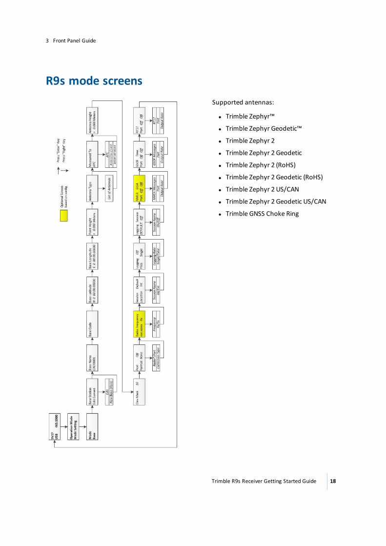
R9s mode screensSupported antennas:
l Trimble Zephyr™
l Trimble Zephyr Geodetic™
l Trimble Zephyr 2
l Trimble Zephyr 2 Geodetic
l Trimble Zephyr 2 (RoHS)
l Trimble Zephyr 2 Geodetic (RoHS)
l Trimble Zephyr 2 US/CAN
l Trimble Zephyr 2 Geodetic US/CAN
l Trimble GNSS Choke Ring
Trimble R9s Receiver Getting Started Guide 18
3 Front Panel Guide
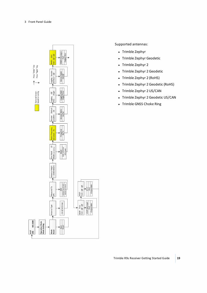
Supported antennas:
l Trimble Zephyr
l Trimble Zephyr Geodetic
l Trimble Zephyr 2
l Trimble Zephyr 2 Geodetic
l Trimble Zephyr 2 (RoHS)
l Trimble Zephyr 2 Geodetic (RoHS)
l Trimble Zephyr 2 US/CAN
l Trimble Zephyr 2 Geodetic US/CAN
l Trimble GNSS Choke Ring
Trimble R9s Receiver Getting Started Guide 19
3 Front Panel Guide
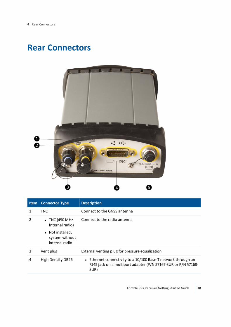
Rear Connectors
Item Connector Type Description
1 TNC Connect to the GNSS antenna
2 l TNC (450 MHz Internal radio)
l Not installed, system without internal radio
Connect to the radio antenna
3 Vent plug External venting plug for pressure equalization
4 High Density DB26 l Ethernet connectivity to a 10/100 Base-T network through an RJ45 jack on a multiport adapter (P/N 57167-SUR or P/N 57168-SUR)
Trimble R9s Receiver Getting Started Guide 20
4 Rear Connectors
Item Connector Type Description
l 'Slave' USB communications through the USB type B connector on the multiport adapter (P/N 57167-SUR)
l 'Host' USB communications through the connector on the 26-pin cable (P/N 58339-SUR)
l Primary power from an external power supply
l External power input from a battery cradle system
l Full 9-wire RS-232 serial communications using the 26-9-pin multiport adapter (P/N 57168-SUR) or a 26-pin serial communications cable
5 Lemo (7-pin/0-shell) l 3 wire RS-232 serial communications using a 7-pin/ 0 shell Lemo cable
l Secondary external power input
Trimble R9s Receiver Getting Started Guide 21
4 Rear Connectors
Configuring System SettingsYou can use the keypad and display of the receiver to configure the following settings:
l Display language
l Display and input units
l Baud rate, parity, data bits, and stop bits for serial ports
l Display power saver
l AutoBase
l Set position precisions
To access the system settings:
1. In the Home screen, press . Use the Operation Mode screen to configure system settings or mode settings, and to view the SV (satellite) status. Mode Settings is the default setting.
2. Press . When the operation mode begins to flash, the receiver is in Edit mode and you can change this setting.
3. Press to change to System Setup.
4. Press to accept the change.
5. Press again.
6. Use the Display Language screen, if required, to change the language. Choose English, Finnish,
French, German, Italian, Spanish, or Swedish. Press to accept the change.
7. Press again. Use the Display and Input Units screen, if required, to change the units to Meters or US Feet.
8. Press to accept the change.
9. Press again. Use the Port Settings screen, if required, to change the port.
10. Press to accept the change.
11. Press again. Use the Screen Pwr Savr screen to choose On, Off, or Auto. If you use the Auto setting, the screen turns off after 60 seconds of inactivity. The Power LED remains lit so that you can tell if the receiver is on or off. If an error message appears, the screen comes back on. Press
to accept the change and then press again to move to the next screen.
12. If you are using an RTK base station, the Autobase warning screen appears.
Trimble R9s Receiver Getting Started Guide 22
5 Configuring System Settings
13. Press to accept the change.
14. Press again. When the Home screen appears, the system setup is complete.
Turning off AutoBase technologyTo turn off AutoBase technology, use either the receiver’s keypad and display or the web interface.
When AutoBase technology is off, you can establish a new base station position in the receiver using the Edit Current or New Base (Here) menus. This does not automatically generate a new application file, but changes the settings in the current application file. When the receiver is turned on again, the most recent settings are always used.
To turn off AutoBase technology using the receiver:
1. In the Home screen, press .
2. Press . When the operation mode begins to flash, the receiver is in Edit mode and you can change this setting.
3. Press to change to System Setup.
4. Press to accept the change.
5. Press again. You start to scroll through options in the System Setup menu.
6. Keep pressing until Autobase appears.
7. Press . The setting On flashes.
8. Press until it displays Off. Press to accept the change.
9. Press again. The Active Appfile screen appears.
To change the application file:
l Press to display START Appfile.
l Press to show SAVE Appfile.
l Press to show DELETE Appfile.
l Press to show START Appfile.
Trimble R9s Receiver Getting Started Guide 23
5 Configuring System Settings
External data logging to an external deviceThe Trimble R9s receiver can log raw GNSS data to an external device (thumb drive or external hard drive). When logging large amounts of raw data to the receiver, the best solution may be to log externally. This gives you an “unlimited” source of memory for logging. To use externally logging, an additional port adapter is required—Trimble part number 58339-SUR. The receiver's display enables you to set up and start up to two data logging sessions. When setting up a data logging session, select internal or external logging.
Setting up an external data logging sessionNote – A data logging session is configurable in either the Base or Rover mode. All settings are available in both settings. If logging data while set up as a base, you must use the Base mode to set up logging.
1. From the display's main screen, press to access the Operation Mode screen. With the
Operation Mode screen set to Mode Setting, press again to move to the Mode screen.
2. On the Mode screen, press , then or to select Base or Rover mode. Press to accept the mode and move to the settings screens.
3. Refer to the required section below to set up in Base mode or to set up in Rover mode.
Set up in Base mode for logging:Note – If setting up an RTK Base and simultaneously logging data, use the first five screens to input or set a base position for the RTK survey.
1. Press until you see the Antenna Type screen. Press , then or to select the type
of GNSS antenna in use. Press to accept the antenna type.
2. On the Measure To screen, press , then or to select the correct height
measurement point on the GNSS antenna. Press to accept the antenna measured to setting.
3. On the Antenna Height screen, press , then or to enter the measured GNSS
antenna height. Press or to move between the numeric decimal places. Press to accept the antenna height.
4. On the Elev Mask screen, press , then or to enter the desired elevation mask for
satellites tracked. Press or to increase or decrease the elevation mask (in degrees).
Press to accept the elevation mask.
Trimble R9s Receiver Getting Started Guide 24
5 Configuring System Settings
5. Do the following if you are setting up an RTK base station and simultaneously logging raw data. If you are only logging data, go to step 6.
a. On the Correction output port and format screen, if you are setting up an RTK base station and logging session, set up the Port and Correction Format for the RTK survey.
b. If an internal radio is installed, on the Radio Frequency screen, press , then or
to select the desired radio frequency of the internal radio. Press to accept the radio frequency.
c. On the Radio Mode screen, select the configuration for your RTK Base Station.
6. Set up the data logging session. The next two screens allow you to set up a logging session. The two screens are related; the second screen settings relate to the previous screen's setting when using two logging sessions.
l l The Session/Location screen enables you to select one of two logging sessions and the storage location of each session.
One session name is set to Default and always available for setup from the receiver's display.
A second session is configurable from the Web Interface using a user-defined name. When the second session is created in the Web Interface / Data Logging menu, the second session is available for configuration and enabling from the receiver's display. On the
Session/Location screen, press , then or to select a session. Press to
move to the Location field, press then or to select the logging location of
internal (Int) or external (Ext). Press to accept the session and location parameters.
l The Logging/Files screen settings relate to the previous screen’s settings. This screen is used to set the logging rate collected and the duration of the logging.
a. Logging Rates: Press , then or to to select a logging rate for your data
logging. Press to move to the Files setting.
b. Files: Press , then or to select a duration for your data logging. Press to accept the settings and move to the next screen.
l a. Single. This mode causes the session to log data whenever it is enabled. A single file is produced. Logging only stops when the available file system space drops to zero or when you disable the session.
l a. 1, 4, or 24 hour. Specific duration times for logging. When the hour file setting is used, the logging starts when the session is enabled and ends after the prescribed duration is met.
l l The Logging Session screen allows you to select and enable the required session. Press
, then
Trimble R9s Receiver Getting Started Guide 25
5 Configuring System Settings
or to select a session to enable, and then press to accept the session. Press
to move to the enable field. Press , then or to select On, and then press
to enable the session. Logging will begin at that moment.
7. Use the remaining screens as required, based on the survey setup. For most data logging, all
the screens are not required. To exit the screens, press until you are at the main screen, or
press briefly to return directly to the main screen.
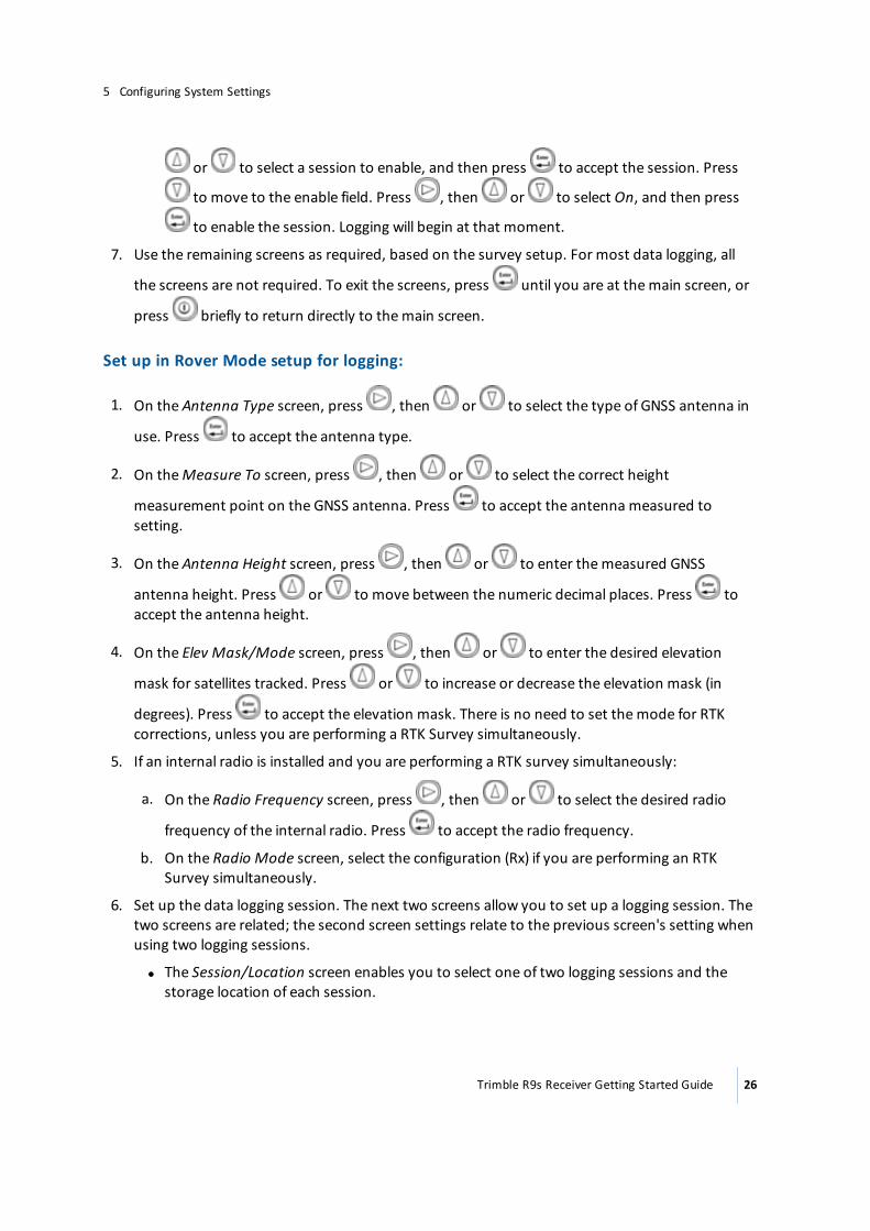
Set up in Rover Mode setup for logging:
1. On the Antenna Type screen, press , then or to select the type of GNSS antenna in
use. Press to accept the antenna type.
2. On the Measure To screen, press , then or to select the correct height
measurement point on the GNSS antenna. Press to accept the antenna measured to setting.
3. On the Antenna Height screen, press , then or to enter the measured GNSS
antenna height. Press or to move between the numeric decimal places. Press to accept the antenna height.
4. On the Elev Mask/Mode screen, press , then or to enter the desired elevation
mask for satellites tracked. Press or to increase or decrease the elevation mask (in
degrees). Press to accept the elevation mask. There is no need to set the mode for RTK corrections, unless you are performing a RTK Survey simultaneously.
5. If an internal radio is installed and you are performing a RTK survey simultaneously:
a. On the Radio Frequency screen, press , then or to select the desired radio
frequency of the internal radio. Press to accept the radio frequency.
b. On the Radio Mode screen, select the configuration (Rx) if you are performing an RTK Survey simultaneously.
6. Set up the data logging session. The next two screens allow you to set up a logging session. The two screens are related; the second screen settings relate to the previous screen's setting when using two logging sessions.
l l The Session/Location screen enables you to select one of two logging sessions and the storage location of each session.
Trimble R9s Receiver Getting Started Guide 26
5 Configuring System Settings
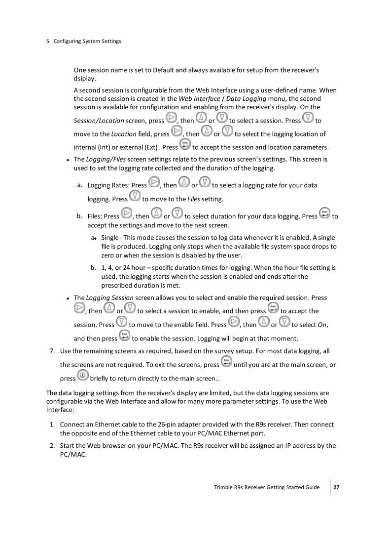
One session name is set to Default and always available for setup from the receiver's dsiplay.
A second session is configurable from the Web Interface using a user-defined name. When the second session is created in the Web Interface / Data Logging menu, the second session is available for configuration and enabling from the receiver's display. On the
Session/Location screen, press , then or to select a session. Press to
move to the Location field, press , then or to select the logging location of
internal (Int) or external (Ext) . Press to accept the session and location parameters.
l The Logging/Files screen settings relate to the previous screen’s settings. This screen is used to set the logging rate collected and the duration of the logging.
a. Logging Rates: Press , then or to select a logging rate for your data
logging. Press to move to the Files setting.
b. Files: Press , then or to select duration for your data logging. Press to accept the settings and move to the next screen.
l a. Single - This mode causes the session to log data whenever it is enabled. A single file is produced. Logging only stops when the available file system space drops to zero or when the session is disabled by the user.
b. 1, 4, or 24 hour – specific duration times for logging. When the hour file setting is used, the logging starts when the session is enabled and ends after the prescribed duration is met.
l The Logging Session screen allows you to select and enable the required session. Press
, then or to select a session to enable, and then press to accept the
session. Press to move to the enable field. Press , then or to select On,
and then press to enable the session. Logging will begin at that moment.
7. Use the remaining screens as required, based on the survey setup. For most data logging, all
the screens are not required. To exit the screens, press until you are at the main screen, or
press briefly to return directly to the main screen..
The data logging settings from the receiver's display are limited, but the data logging sessions are configurable via the Web Interface and allow for many more parameter settings. To use the Web Interface:
1. Connect an Ethernet cable to the 26-pin adapter provided with the R9s receiver. Then connect the opposite end of the Ethernet cable to your PC/MAC Ethernet port.
2. Start the Web browser on your PC/MAC. The R9s receiver will be assigned an IP address by the PC/MAC.
Trimble R9s Receiver Getting Started Guide 27
5 Configuring System Settings

3. Press from the main screen of the receiver's display to see the assigned IP Address of the R9s. Enter the display IP address into the browser URL field. The R9s receiver's Web Interface is displayed.
4. Enter the username and password for the receiver. The default username is admin and the default password is password.
Trimble R9s Receiver Getting Started Guide 28
5 Configuring System Settings
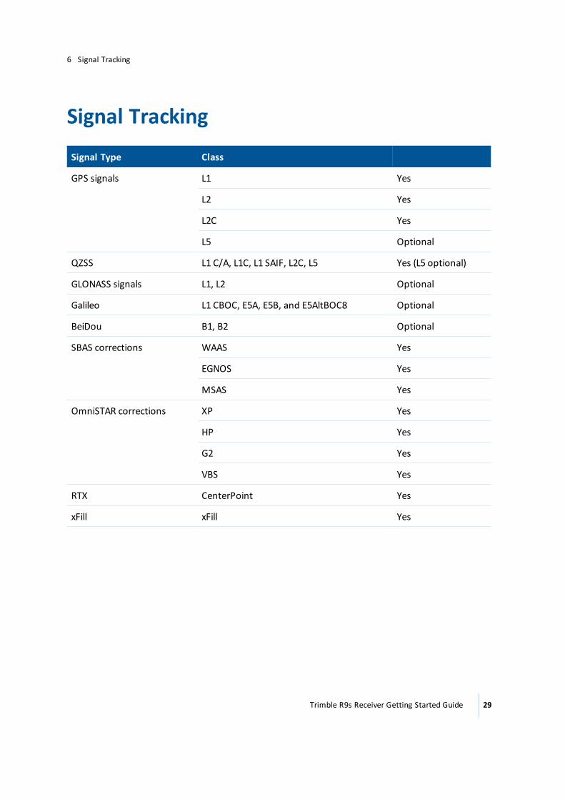
Signal Tracking
Signal Type Class
GPS signals L1 Yes
L2 Yes
L2C Yes
L5 Optional
QZSS L1 C/A, L1C, L1 SAIF, L2C, L5 Yes (L5 optional)
GLONASS signals L1, L2 Optional
Galileo L1 CBOC, E5A, E5B, and E5AltBOC8 Optional
BeiDou B1, B2 Optional
SBAS corrections WAAS Yes
EGNOS Yes
MSAS Yes
OmniSTAR corrections XP Yes
HP Yes
G2 Yes
VBS Yes
RTX CenterPoint Yes
xFill xFill Yes
Trimble R9s Receiver Getting Started Guide 29
6 Signal Tracking
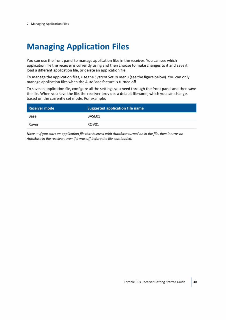
Managing Application FilesYou can use the front panel to manage application files in the receiver. You can see which application file the receiver is currently using and then choose to make changes to it and save it, load a different application file, or delete an application file.
To manage the application files, use the System Setup menu (see the figure below). You can only manage application files when the AutoBase feature is turned off.
To save an application file, configure all the settings you need through the front panel and then save the file. When you save the file, the receiver provides a default filename, which you can change, based on the currently set mode. For example:
Receiver mode Suggested application file name
Base BASE01
Rover ROV01
Note – If you start an application file that is saved with AutoBase turned on in the file, then it turns on AutoBase in the receiver, even if it was off before the file was loaded.
Trimble R9s Receiver Getting Started Guide 30
7 Managing Application Files
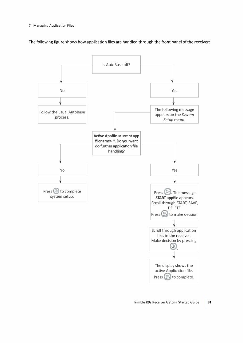
The following figure shows how application files are handled through the front panel of the receiver:
Trimble R9s Receiver Getting Started Guide 31
7 Managing Application Files
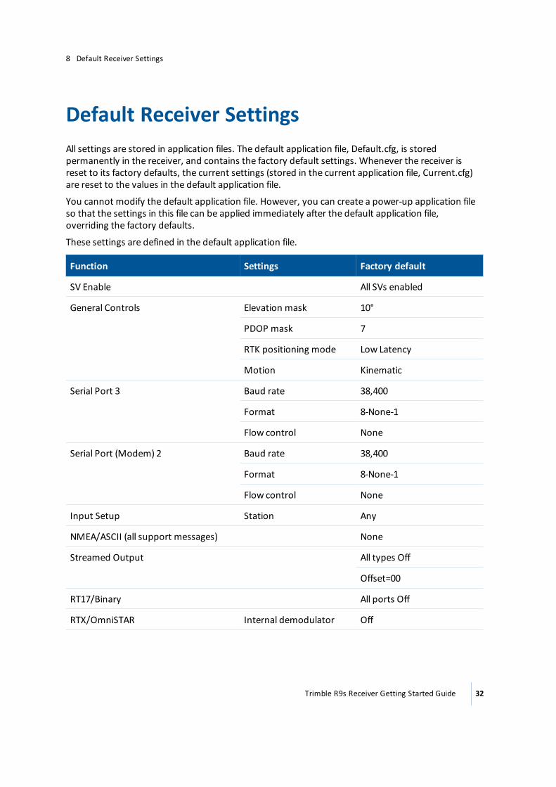
Default Receiver Settings All settings are stored in application files. The default application file, Default.cfg, is stored permanently in the receiver, and contains the factory default settings. Whenever the receiver is reset to its factory defaults, the current settings (stored in the current application file, Current.cfg) are reset to the values in the default application file.
You cannot modify the default application file. However, you can create a power-up application file so that the settings in this file can be applied immediately after the default application file, overriding the factory defaults.
These settings are defined in the default application file.
Function Settings Factory default
SV Enable All SVs enabled
General Controls Elevation mask 10°
PDOP mask 7
RTK positioning mode Low Latency
Motion Kinematic
Serial Port 3 Baud rate 38,400
Format 8-None-1
Flow control None
Serial Port (Modem) 2 Baud rate 38,400
Format 8-None-1
Flow control None
Input Setup Station Any
NMEA/ASCII (all support messages) None
Streamed Output All types Off
Offset=00
RT17/Binary All ports Off
RTX/OmniSTAR Internal demodulator Off
Trimble R9s Receiver Getting Started Guide 32
8 Default Receiver Settings
Function Settings Factory default
Antenna Type Zephyr Geodetic Model 2
Height (true vertical) 0.00 m
Measurement method Antenna Phase Center
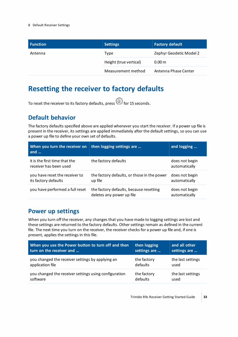
Resetting the receiver to factory defaults
To reset the receiver to its factory defaults, press for 15 seconds.
Default behaviorThe factory defaults specified above are applied whenever you start the receiver. If a power up file is present in the receiver, its settings are applied immediately after the default settings, so you can use a power up file to define your own set of defaults.
When you turn the receiver on and …
then logging settings are … and logging …
it is the first time that the receiver has been used
the factory defaults does not begin automatically
you have reset the receiver to its factory defaults
the factory defaults, or those in the power up file
does not begin automatically
you have performed a full reset the factory defaults, because resetting deletes any power up file
does not begin automatically
Power up settingsWhen you turn off the receiver, any changes that you have made to logging settings are lost and these settings are returned to the factory defaults. Other settings remain as defined in the current file. The next time you turn on the receiver, the receiver checks for a power up file and, if one is present, applies the settings in this file.
When you use the Power button to turn off and then turn on the receiver and …
then logging settings are …
and all other settings are …
you changed the receiver settings by applying an application file
the factory defaults
the last settings used
you changed the receiver settings using configuration software
the factory defaults
the last settings used
Trimble R9s Receiver Getting Started Guide 33
8 Default Receiver Settings
Adding Radio Frequencies
Setting UHF reception radio frequencies using the web interfaceTo enter your own Receive (Rx) frequency using the web interface:
1. Select the Radio menu.
2. Select the Frequency Management submenu.
3. Make a note of the details shown in the Frequency range and Tuning step fields. Any new frequencies must be within the range shown and must also be a multiple of the KHz shown in the Tuning step field.
4. Select the Add Channel option and then enter the new channel frequency.
5. Click OK.
To delete a channel frequency:
1. Select the Delete channel option.
2. Select a channel to delete from the list that appears.
You cannot add or delete Transmit (Tx) channels using the web interface.
Trimble R9s Receiver Getting Started Guide 34
9 Adding Radio Frequencies
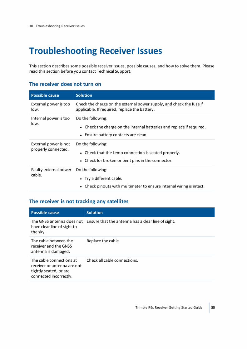
Troubleshooting Receiver IssuesThis section describes some possible receiver issues, possible causes, and how to solve them. Please read this section before you contact Technical Support.
The receiver does not turn on
Possible cause Solution
External power is too low.
Check the charge on the external power supply, and check the fuse if applicable. If required, replace the battery.
Internal power is too low.
Do the following:
l Check the charge on the internal batteries and replace if required.
l Ensure battery contacts are clean.
External power is not properly connected.
Do the following:
l Check that the Lemo connection is seated properly.
l Check for broken or bent pins in the connector.
Faulty external power cable.
Do the following:
l Try a different cable.
l Check pinouts with multimeter to ensure internal wiring is intact.
The receiver is not tracking any satellites
Possible cause Solution
The GNSS antenna does not have clear line of sight to the sky.
Ensure that the antenna has a clear line of sight.
The cable between the receiver and the GNSS antenna is damaged.
Replace the cable.
The cable connections at receiver or antenna are not tightly seated, or are connected incorrectly.
Check all cable connections.
Trimble R9s Receiver Getting Started Guide 35
10 Troubleshooting Receiver Issues
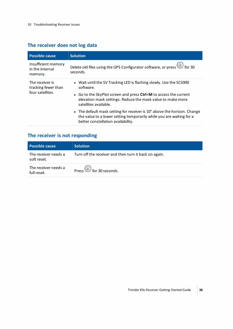
The receiver does not log data
Possible cause Solution
Insufficient memory in the internal memory.
Delete old files using the GPS Configurator software, or press for 30 seconds.
The receiver is tracking fewer than four satellites.
l Wait until the SV Tracking LED is flashing slowly. Use the SCS900 software.
l Go to the SkyPlot screen and press Ctrl+M to access the current elevation mask settings. Reduce the mask value to make more satellites available.
l The default mask setting for receiver is 10° above the horizon. Change the value to a lower setting temporarily while you are waiting for a better constellation availability.
The receiver is not responding
Possible cause Solution
The receiver needs a soft reset.
Turn off the receiver and then turn it back on again.
The receiver needs a full reset. Press for 30 seconds.
Trimble R9s Receiver Getting Started Guide 36
10 Troubleshooting Receiver Issues
Glossary
1PPS Pulse-per-second. Used in hardware timing. A pulse is generated in conjunction with a time stamp. This defines the instant when the time stamp is applicable.
almanac A file that contains orbit information on all the satellites, clock corrections, and atmospheric delay parameters. The almanac is transmitted by a GNSS satellite to a GNSS receiver, where it facilitates rapid acquisition of GNSS signals when you start collecting data, or when you have lost track of satellites and are trying to regain GNSS signals.The orbit information is a subset of the ephemeris/ephemerides data.
AutoBase AutoBase technology uses the position of the receiver to automatically select the correct base station; allowing for one button press operation of a base station. It shortens setup time associated with repeated daily base station setups at the same location on jobsites.
base station Also called reference station. In construction, a base station is a receiver placed at a known point on a jobsite that tracks the same satellites as an RTK rover, and provides a real-time differential correction message stream through radio to the rover, to obtain centimeter level positions on a continuous real-time basis. A base station can also be a part of a virtual reference station network, or a location at which GNSS observations are collected over a period of time, for subsequent postprocessing to obtain the most accurate position for the location.
BeiDou The BeiDou Navigation Satellite System (also known as BDS ) is a Chinese satellite navigation system.The first BeiDou system (known as BeiDou-1), consists of four satellites and has limited coverage and applications. It has been offering navigation services mainly for customers in China and from neighboring regions since 2000.The second generation of the system (known as BeiDou-2) consists of satellites in a combination of geostationary, inclined geosynchronous, and medium earth orbit configurations. It became operational with coverage of China in December 2011. However, the complete Interface Control Document (which specifies the satellite messages) was not released until December 2012. BeiDou-2 is a regional navigation service which offers services to customers in the Asia-Pacific region. A third generation of the BeiDou system is planned, which will expand coverage globally. This generation is currently scheduled to be completed by 2020.
BINEX BInary EXchange format. BINEX is an operational binary format standard for GPS/GLONASS/SBAS research purposes. It is designed to
Trimble R9s Receiver Getting Started Guide 37
grow and allow encapsulation of all (or most) of the information currently allowed for in a range of other formats.
broadcast server An Internet server that manages authentication and password control for a network of VRS servers, and relays VRS corrections from the VRS server that you select.
carrier A radio wave having at least one characteristic (such as frequency, amplitude, or phase) that can be varied from a known reference value by modulation.
carrier frequency The frequency of the unmodulated fundamental output of a radio transmitter. The GPS L1 carrier frequency is 1575.42 MHz.
carrier phase Is the cumulative phase count of the GPS or GLONASS carrier signal at a given time.
cellular modems A wireless adapter that connects a laptop computer to a cellular phone system for data transfer. Cellular modems, which contain their own antennas, plug into a PC Card slot or into the USB port of the computer and are available for a variety of wireless data services such as GPRS.
CMR/CMR+ Compact Measurement Record. A real-time message format developed by Trimble for broadcasting corrections to other Trimble receivers. CMR is a more efficient alternative to RTCM.
CMRx A real-time message format developed by Trimble for transmitting more satellite corrections resulting from more satellite signals, more constellations, and more satellites. Its compactness means more repeaters can be used on a site.
covariance A statistical measure of the variance of two random variables that are observed or measured in the same mean time period. This measure is equal to the product of the deviations of corresponding values of the two variables from their respective means.
datum Also called geodetic datum. A mathematical model designed to best fit the geoid, defined by the relationship between an ellipsoid and, a point on the topographic surface, established as the origin of the datum. World geodetic datums are typically defined by the size and shape of an ellipsoid and the relationship between the center of the ellipsoid and the center of the earth.Because the earth is not a perfect ellipsoid, any single datum will provide a better model in some locations than in others. Therefore, various datums have been established to suit particular regions.For example, maps in Europe are often based on the European datum of 1950 (ED-50). Maps in the United States are often based on the North American datum of 1927 (NAD-27) or 1983 (NAD-83).All GPS coordinates are based on the WGS-84 datum surface.
deep discharge Withdrawal of all electrical energy to the end-point voltage before the
Trimble R9s Receiver Getting Started Guide 38
cell or battery is recharged.
DGPS See real-time differential GPS.
differential correction Differential correction is the process of correcting GNSS data collected on a rover with data collected simultaneously at a base station. Because the base station is on a known location, any errors in data collected at the base station can be measured, and the necessary corrections applied to the rover data.Differential correction can be done in real-time, or after the data is collected by postprocessing.
differential GPS See real-time differential GPS.
DOP Dilution of Precision. A measure of the quality of GNSS positions, based on the geometry of the satellites used to compute the positions. When satellites are widely spaced relative to each other, the DOP value is lower, and position precision is greater. When satellites are close together in the sky, the DOP is higher and GNSS positions may contain a greater level of error.PDOP (Position DOP) indicates the three-dimensional geometry of the satellites. Other DOP values include HDOP(Horizontal DOP) and VDOP (Vertical DOP), which indicate the precision of horizontal measurements (latitude and longitude) and vertical measurements respectively. PDOP is related to HDOP and VDOP as follows: PDOP² = HDOP² + VDOP².
dual-frequency GPS A type of receiver that uses both L1 and L2 signals from GPS satellites. A dual-frequency receiver can compute more precise position fixes over longer distances and under more adverse conditions because it compensates for ionospheric delays.
EGNOS European Geostationary Navigation Overlay Service. A Satellite-Based Augmentation System (SBAS) that provides a free-to-air differential correction service for GNSS. EGNOS is the European equivalent of WAAS, which is available in the United States.
elevation The vertical distance from a geoid such as EGM96 to the antenna phase center. The geoid is sometimes referred to as Mean Sea Level.
elevation mask The angle below which the receiver will not track satellites. Normally set to 10 degrees to avoid interference problems caused by buildings and trees, atmospheric issues, and multipath errors.
ellipsoid An ellipsoid is the three-dimensional shape that is used as the basis for mathematically modeling the earth’s surface. The ellipsoid is defined by the lengths of the minor and major axes. The earth’s minor axis is the polar axis and the major axis is the equatorial axis.
EHT Height above ellipsoid.
ephemeris/ephemerides A list of predicted (accurate) positions or locations of satellites as a
Trimble R9s Receiver Getting Started Guide 39
function of time. A set of numerical parameters that can be used to determine a satellite’s position. Available as broadcast ephemeris or as postprocessed precise ephemeris.
epoch The measurement interval of a GNSS receiver. The epoch varies according to the measurement type: for real-time measurement it is set at one second; for postprocessed measurement it can be set to a rate of between one second and one minute. For example, if data is measured every 15 seconds, loading data using 30-second epochs means loading every alternate measurement.
feature A feature is a physical object or event that has a location in the real world, which you want to collect position and/or descriptive information (attributes) about. Features can be classified as surface or non-surface features, and again as points, lines/break lines, or boundaries/areas.
firmware The program inside the receiver that controls receiver operations and hardware.
Galileo Galileo is a GNSS system built by the European Union and the European Space Agency. It is complimentary to GPS and GLONASS.
geoid The geoid is the equipotential surface that would coincide with the mean ocean surface of the Earth. For a small site this can be approximated as an inclined plane above the Ellipsoid.
GHT Height above geoid.
GLONASS Global Orbiting Navigation Satellite System. GLONASS is a Soviet space-based navigation system comparable to the American GPS system. The operational system consists of 21 operational and 3 non-operational satellites in 3 orbit planes.
GNSS Global Navigation Satellite System.
GSOF General Serial Output Format. A Trimble proprietary message format.
HDOP Horizontal Dilution of Precision. HDOP is a DOP value that indicates the precision of horizontal measurements. Other DOP values include VDOP (vertical DOP) and PDOP (Position DOP).Using a maximum HDOP is ideal for situations where vertical precision is not particularly important, and your position yield would be decreased by the vertical component of the PDOP (for example, if you are collecting data under canopy).
height The vertical distance above the Ellipsoid. The classic Ellipsoid used in GPS is WGS-84.
IBSS Internet Base Station Service. This Trimble service makes the setup of an Internet-capable receiver as simple as possible. The base station can be connected to the Internet (cable or wirelessly). To access the distribution server, the user enters a password into the receiver. To
Trimble R9s Receiver Getting Started Guide 40
use the server, the user must have a Trimble Connected Community site license.
ITRF2008 The ITRF2008 datum is the current realization of the International Terrestrial Reference System (ITRS). This datum can be transformed to ITRF2008 epoch 2005 (fixed), or be used in the current epoch. The fixed epoch allows for selecting individual tectonic plates that have been closely modeled to the actual current location. However, there may be large differences due to natural events (such as earthquakes) or proximity to the perimeter of a tectonic plate.
L1 The primary L-band carrier used by GPS and GLONASS satellites to transmit satellite data.
L2 The secondary L-band carrier used by GPS and GLONASS satellites to transmit satellite data.
L2C A modernized code that allows significantly better ability to track the L2 frequency.
L5 The third L-band carrier used by GPS satellites to transmit satellite data. L5 will provide a higher power level than the other carriers. As a result, acquiring and tracking weak signals will be easier.
Mountpoint Every single NTripSource needs a unique mountpoint on an NTripCaster. Before transmitting GNSS data to the NTripCaster, the NTripServer sends an assignment of the mountpoint.
MSAS MTSAT Satellite-Based Augmentation System. A Satellite-Based Augmentation System (SBAS) that provides a free-to-air differential correction service for GNSS. MSAS is the Japanese equivalent of WAAS, which is available in the United States.
multipath Interference, similar to ghosts on an analog television screen that occurs when GNSS signals arrive at an antenna having traversed different paths. The signal traversing the longer path yields a larger pseudorange estimate and increases the error. Multiple paths can arise from reflections off the ground or off structures near the antenna.
NMEA National Marine Electronics Association. NMEA 0183 defines the standard for interfacing marine electronic navigational devices. This standard defines a number of 'strings' referred to as NMEA strings that contain navigational details such as positions. Most Trimble GNSS receivers can output positions as NMEA strings.
NTrip Protocol Networked Transport of RTCM via Internet Protocol (NTrip) is an application-level protocol that supports streaming Global Navigation Satellite System (GNSS) data over the Internet. NTrip is a generic, stateless protocol based on the Hypertext Transfer Protocol (HTTP). The HTTP objects are extended to GNSS data streams.
Trimble R9s Receiver Getting Started Guide 41
NTripCaster The NTripCaster is basically an HTTP server supporting a subset of HTTP request/response messages and adjusted to low-bandwidth streaming data. The NTripCaster accepts request messages on a single port from either the NTripServer or the NTripClient. Depending on these messages, the NTripCaster decides whether there is streaming data to receive or to send.Trimble NTripCaster integrates the NTripServer and the NTripCaster. This port is used only to accept requests from NTripClients.
NTripClient An NTripClient will be accepted by and receive data from an NTripCaster, if the NTripClient sends the correct request message (TCP/UDP connection to the specified NTripCaster IP and listening port).
NTripServer The NTripServer is used to transfer GNSS data of an NTripSource to the NTripCaster. An NTripServer in its simplest setup is a computer program running on a PC that sends correction data of an NTripSource (for example, as received through the serial communication port from a GNSS receiver) to the NTripCaster.The NTripServer - NTripCaster communication extends HTTP by additional message formats and status codes.
NTripSource The NTripSources provide continuous GNSS data (for example, RTCM-104 corrections) as streaming data. A single source represents GNSS data referring to a specific location. Source description parameters are compiled in the source-table.
OmniSTAR The OmniSTAR HP/XP service allows the use of new generation dual-frequency receivers with the OmniSTAR service. The HP/XP service does not rely on local reference stations for its signal, but utilizes a global satellite monitoring network. Additionally, while most current dual-frequency GNSS systems are accurate to within a meter or so, OmniSTAR with XP is accurate in 3D to better than 30 cm.
Orthometric elevation The Orthometric Elevation is the height above the geoid (often termed the height above the 'Mean Sea Level').
PDOP Position Dilution of Precision. PDOP is a DOP value that indicates the precision of three-dimensional measurements. Other DOP values include VDOP (vertical DOP) and HDOP (Horizontal Dilution of Precision).Using a maximum PDOP value is ideal for situations where both vertical and horizontal precision are important.
postprocessing Postprocessing is the processing of satellite data after it is collected, in order to eliminate error. This involves using computer software to compare data from the rover with data collected at the base station.
QZSS Quasi-Zenith Satellite System. A Japanese regional GNSS, eventually consisting of three geosynchronous satellites over Japan.
Trimble R9s Receiver Getting Started Guide 42
real-time differential GPS
Also known as real-time differential correction or DGPS. Real-time differential GPS is the process of correcting GPS data as you collect it. Corrections are calculated at a base station and then sent to the receiver through a radio link. As the rover receives the position it applies the corrections to give you a very accurate position in the field.Most real-time differential correction methods apply corrections to code phase positions.While DGPS is a generic term, its common interpretation is that it entails the use of single-frequency code phase data sent from a GNSS base station to a rover GNSS receiver to provide submeter position . The rover receiver can be at a long range (greater than 100 kms (62 miles)) from the base station.
rover A rover is any mobile GNSS receiver that is used to collect or update data in the field, typically at an unknown location.
Roving mode Roving mode applies to the use of a rover receiver to collect data, stakeout, or control machinery in real time using RTK techniques.
RTCM Radio Technical Commission for Maritime Services. A commission established to define a differential data link for the real-time differential correction of roving GNSS receivers. There are three versions of RTCM correction messages. All Trimble GNSS receivers use Version 2 protocol for single-frequency DGPS type corrections. Carrier phase corrections are available on Version 2, or on the newer Version 3 RTCM protocol, which is available on certain Trimble dual-frequency receivers. The Version 3 RTCM protocol is more compact but is not as widely supported as Version 2.
RTK Real-time kinematic. A real-time differential GPS method that uses carrier phase measurements for greater .
RTX Trimble RTX (Real Time eXtended) is a high accuracy GNSS correction service. This breakthrough technology provides real-time corrections without the use of a traditional reference station-based infrastructure. The delivery of the correction service is the same as OmniSTAR, as they are both Mobile Satellite Services (MSS). However, the method in which the correction is calculated is different and is more accurate with RTX.
SBAS Satellite-Based Augmentation System. SBAS is based on differential GPS, but applies to wide area (WAAS/EGNOS/MSAS) networks of reference stations. Corrections and additional information are broadcast using geostationary satellites.
signal-to-noise ratio SNR. The signal strength of a satellite is a measure of the information content of the signal, relative to the signal’s noise. The typical SNR of a satellite at 30° elevation is between 47 and 50 dB-Hz.
skyplot The satellite skyplot confirms reception of a differentially corrected GNSS signal and displays the number of satellites tracked by the GNSS
Trimble R9s Receiver Getting Started Guide 43
receiver, as well as their relative positions.
SNR See signal-to-noise ratio.
Source-table The NTripCaster maintains a source-table containing information on available NTripSources, networks of NTripSources, and NTripCasters, to be sent to an NTripClient on request. Source-table records are dedicated to one of the following:
l data STReams (record type STR)
l CASters (record type CAS)
l NETworks of data streams (record type NET)
All NTripClients must be able to decode record type STR. Decoding types CAS and NET is an optional feature. All data fields in the source-table records are separated using the semicolon character.
triple frequency GPS A type of receiver that uses three carrier phase measurements (L1, L2, and L5).
UTC Universal Time Coordinated. A time standard based on local solar mean time at the Greenwich meridian.
xFill Trimble xFill™ is a new service that extends RTK positioning for several minutes when the RTK correction stream is temporarily unavailable. The Trimble xFill service improves field productivity by reducing downtime waiting to re-establish RTK corrections in black spots. It can even expand productivity by allowing short excursions into valleys and other locations where continuous correction messages were not previously possible. Proprietary Trimble xFill corrections are broadcast by satellite and are generally available on construction sites globally where the GNSS constellations are also visible. It applies to any positioning task being performed with a single-base, Trimble Internet Base Station Service (IBSS), or VRS™ RTK correction source.
variance A statistical measure used to describe the spread of a variable in the mean time period. This measure is equal to the square of the deviation of a corresponding measured variable from its mean. See also covariance.
VDOP Vertical Dilution of Precision. VDOP is a DOP value (dimensionless number) that indicates the quality of GNSS observations in the vertical frame.
VRS Virtual Reference Station. A VRS system consists of GNSS hardware, software, and communication links. It uses data from a network of base stations to provide corrections to each rover that are more accurate than corrections from a single base station.To start using VRS corrections, the rover sends its position to the VRS server. The VRS server uses the base station data to model systematic errors (such as ionospheric noise) at the rover position. It then sends
Trimble R9s Receiver Getting Started Guide 44
RTCM correction messages back to the rover.
WAAS Wide Area Augmentation System. WAAS was established by the Federal Aviation Administration (FAA) for flight and approach navigation for civil aviation. WAAS improves the accuracy and availability of the basic GNSS signals over its coverage area, which includes the continental United States and outlying parts of Canada and Mexico.The WAAS system provides correction data for visible satellites. Corrections are computed from ground station observations and then uploaded to two geostationary satellites. This data is then broadcast on the L1 frequency, and is tracked using a channel on the GNSS receiver, exactly like a GNSS satellite.Use WAAS when other correction sources are unavailable, to obtain greater accuracy than autonomous positions. For more information on WAAS, refer to the FAA website at http://gps.faa.gov.The EGNOS service is the European equivalent and MSAS is the Japanese equivalent of WAAS.
WGS-84 World Geodetic System 1984. Since January 1987, WGS-84 has superseded WGS-72 as the datum used by GPS.The WGS-84 datum is based on the ellipsoid of the same name.
Trimble R9s Receiver Getting Started Guide 45