Trike-Bike Assembly Manual · Trike-Bike™ Assembly Manual © Trike-Bike™ Assembly Manual 2016 ...
12
Trike-Bike ™ Assembly Manual © Trike-Bike™ Assembly Manual 2016 www.trike-bike.com.au Page 1 of 12 Be sure to check our website for more instruction details, videos and photographs as well as a complete listing of each Nut and Bolt for the Trike Bike. www.Trike-Bike.com.au Go to the page marked ASSEMBLY INSTRUCTIONS and take the time to watch our video Congratulations on your purchase of a Trike-Bike™, please take the time to read through this manual to assist with the assembly process. You will need the following tools. Adjustable wrench, also known as Crescent wrench Selection of metric spanners Screw driver, normal and Phillips head Metric Allen keys Nice cup of Tea or Coffee to go along with these instructions Your Trike-Bike™ has been supplied in two boxes, the larger box weighing 26 kg includes all the major parts for the Trike-Bike™ and the second smaller box contains the large basket to go on the rear of the Trike-Bike™ as well as the small basket to go on the front of the Trike-Bike™. Using a sharp knife, cut open the Trike-Bike™ box and make sure that you cut it so you can use the cardboard box to protect the Trike-Bike™ from being scratched during assembly. Lay the cardboard on the ground as your work area and conveniently place and familiarize yourself with the other parts. In the small box shown in the bottom left-hand corner of the photograph above left is all the hardware required to assemble the bike including LED light, chain, seatpost, reflectors, front brake, brake cables, pedals and other associated hardware, nuts and bolts etc. for the assembly. The major packages are shown in the photo on the left. The Trike-Bike™ meets Australian design rules and has the required reflectors for fitting. The yellow reflectors go on each wheel and attach to the spokes, the white reflector goes on the front basket and the two red reflectors go on the rear mud guards, facing backwards. Reflectors are permanently attached to the pedals.
Transcript of Trike-Bike Assembly Manual · Trike-Bike™ Assembly Manual © Trike-Bike™ Assembly Manual 2016 ...

Trike-Bike™ Assembly Manual
© Trike-Bike™ Assembly Manual 2016 www.trike-bike.com.au Page 1 of 12
Be sure to check our website for more instruction details, videos and photographs as well as a complete listing of each Nut and Bolt for the Trike Bike. www.Trike-Bike.com.au
Go to the page marked ASSEMBLY INSTRUCTIONS and take the time to watch our video
Congratulations on your purchase of a Trike-Bike™, please take the time to read through this manual to assist with the assembly process. You will need the following tools.
Adjustable wrench, also known as
Crescent wrench
Selection of metric spanners
Screw driver, normal and Phillips
head Metric Allen keys
Nice cup of Tea or Coffee to go along with
these instructions
Your Trike-Bike™ has been supplied in two boxes, the larger box weighing 26 kg includes all the major parts for the Trike-Bike™ and the second smaller box contains the large basket to go on the rear of the Trike-Bike™ as well as the small basket to go on the front of the Trike-Bike™. Using a sharp knife, cut open the Trike-Bike™ box and make sure that you cut it so you can use the cardboard box to protect the Trike-Bike™ from being scratched during assembly. Lay the cardboard on the ground as your work area and conveniently place and familiarize yourself with the other parts.
In the small box shown in the bottom left-hand corner of the photograph above left is all the hardware required to assemble the bike including LED light, chain, seatpost, reflectors, front brake, brake cables, pedals and other associated hardware, nuts and bolts etc. for the assembly. The major packages are shown in the photo on the left.
The Trike-Bike™ meets Australian design rules and has the required reflectors for fitting. The yellow reflectors go on each wheel and attach to the spokes, the white reflector goes on the front basket and the two red reflectors go on the rear mud guards, facing backwards. Reflectors are permanently attached to the pedals.

Trike-Bike™ Assembly Manual
© Trike-Bike™ Assembly Manual 2016 www.trike-bike.com.au Page 2 of 12
To start assembling your Trike-Bike™ it’s necessary to complete a lot of smaller subassemblies first and then everything falls together very rapidly. We have found with experience that the following assembly sequence is by far the easiest. Again make sure you have the proper tools available, the necessary time without distractions and enjoy assembling your Trike-Bike™.
Firstly, find and locate the two rear mud guards which are protected by cardboard on each end and plastic over the rest of the mud guard. We would recommend leaving the plastic on the mud guard for as long as possible to avoid it getting scratched. Fit the two red reflectors as shown in the photograph to each of the rear mud guards. Tighten the nut behind with an 8mm spanner and remember that you are not putting together a bulldozer so it’s not necessary to over tighten anything on the Trike-Bike™. Note: The two holes at the ends of each mudgaurd sometimes need to be drilled out a little because they clog with paint, if you have difficulty in getting the bolts through then run a 5mm ⌀ drill through the holes to clean them out.
Fit the rear mud guards to their support brackets as shown in the photograph. At this stage do not tighten the bolts which secure the rear mud guards to the frames. Take note: the position of the frames as shown in the photograph with the flat section of the frame toward the inside of the photograph. This gives the correct mounting orientation later in the assembly. Also note: that a lot of the bolts are left loose until final assembly so everything can be adjusted and aligned correctly, it’s not necessary to tighten every bolt immediately.
Locate the two chrome support frames which go on the front mud guard and also on the front basket. The support frame which has a circular end as shown on the left hand side of this photograph is used for the front mud guard. The support frame with the square end attaches to the bottom of the front basket.

Trike-Bike™ Assembly Manual
© Trike-Bike™ Assembly Manual 2016 www.trike-bike.com.au Page 3 of 12
Locate the necessary hardware to fit the front support bracket to the bottom rear of the front mud guard as shown in the photograph. Make sure everything is aligned correctly and centrally before tightening the bolts.
This is a rear view of the front mud guard showing the threaded fitting used to secure the mudguard bracket in place.
Now attach the support bracket with the square ends to the bottom of the front basket.
Make sure that the support bracket is aligned in the center of the basket before tightening the nuts and bolts on the bracket which holds the support bracket in place. The bolts are philips head on top and 8mm nuts on the bottom.

Trike-Bike™ Assembly Manual
© Trike-Bike™ Assembly Manual 2016 www.trike-bike.com.au Page 4 of 12
Locate and partially unwrap the main rear axle assembly. Remove the bubble wrap from the end of the mounting tabs as shown in the photograph.
Please locate both rear wheels. They are similar in every respect except the wheel used on the right-hand-side (as you are sitting on the Trike) has a special cut out as shown in this photograph on the inside of one of the hubs. This cut out meets with a special collar permanently attached to the right-hand-side rear axle. This alignment determines which wheel is the left wheel and which wheel is the right wheel. Note: The Trike-Bike has two back wheels but only the right wheel is used for drive and braking, the left wheel turns freely. This is completely normal and is common on all Trikes.
Be sure to check our website for more instruction details, videos and photographs as well as a complete listing of each Nut and Bolt for the Trike Bike. www.Trike-Bike.com.au
Go to the page marked ASSEMBLY INSTRUCTIONS and take the time to watch our video

Trike-Bike™ Assembly Manual
© Trike-Bike™ Assembly Manual 2016 www.trike-bike.com.au Page 5 of 12
Notice the special cut out on the collar in this photograph. This is the correct side for fitting the right-hand wheel as shown above. The assembly order is, slide the wheel onto the shaft, align with the hub and push on. Then fit the silver washer, fit the normal nut and finally fit the dome nut. Always do the right hand side first. The dome nut is there as a safety precaution to stop people catching their clothes on the end of the axle and must be fitted, it also acts as a lock nut to stop the other nut from coming undone. Use Loctite (or nail polish on the thread) to stop these nuts coming undone.
Do exactly the same for the left-hand wheel except the assembly order is large spacer first, then wheel, then washer, then nut and finally the dome nut. Tighten firmly but not too tight, if you over tighten this side you may hear a scraping sound inside the wheel assembly and it will be difficult to turn the pedals when the chain Is finally connected but most importantly it will overload and damage the outside driveshaft bearings!
Photographs showing the rear axle connected to frame align by eye to be at 90 degrees to the frame. The rear axle assembly is held to the mainframe by six bolts. These bolts have a domed head with a square section immediately under the head which holds them in position whilst they are being tightened. You will notice already that two bolts near the brake assembly are already in position. The correct assembly sequence is bolt through the rear axle assembly and then through the frame, place a washer and then tighten up the nyloc nut firmly.

Trike-Bike™ Assembly Manual
© Trike-Bike™ Assembly Manual 2016 www.trike-bike.com.au Page 6 of 12
We now move to the front of the Trike-Bike™ and it is very easy to fit the front wheel into the forks. Remove the nut and two washers from each side of the front wheel axle. With the wheel in place on the front forks slide the front mud guard into place and then fit the front brake caliper. The correct sequence for fitting the front brakes is the front brake assembly first followed by the small tab which holds the front mud guard, this then goes through the front fork frame, on the rear goes the washer and then finally the dome nut. * NOTE: new model with front disc brake is being introduced; instructions at rear of manual
Down at the front axle we firstly fit the special washer with a tab on the end with the tab inserted into the frame. This is done to prevent the front wheel falling out if ever the nuts come loose. Then fit the support bracket for the front basket, the support bracket for the front mud guard, the normal washer and then finally the nut. When everything is in position and aligned correctly tightened the nuts firmly. Finally, fit the supplied plastic end caps to the exposed axle to prevent your clothes from being caught on the end of the front axles.
The front basket attaches to the top of the steering yoke as shown in the photographs
The front handlebar assembly is now fitted into the front fork assembly; everything is aligned so it is right angles to the front wheel and then the handlebar unit is secured by tightening the hidden bolt with the Allen key as shown in this photograph.
Make sure the handlebar post is inserted at least 75 mm into the front fork assembly. Make sure this bolt is tight, at the same time it will be necessary to adjust the angle of the front handlebars again by using an Allen key on the front side of the handlebar clamp.
Trike-Bike™ Assembly Manual
© Trike-Bike™ Assembly Manual 2016 www.trike-bike.com.au Page 7 of 12
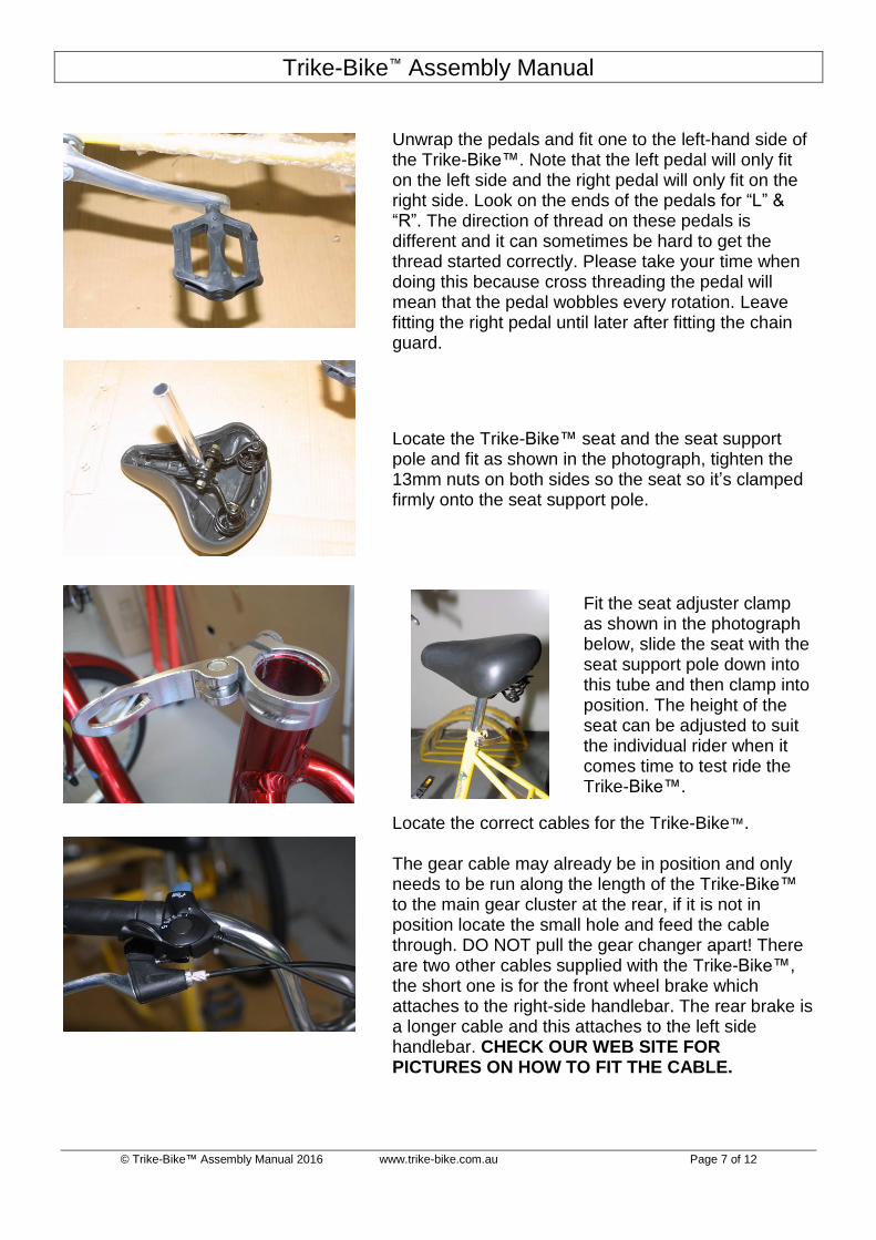
Unwrap the pedals and fit one to the left-hand side of the Trike-Bike™. Note that the left pedal will only fit on the left side and the right pedal will only fit on the right side. Look on the ends of the pedals for “L” & “R”. The direction of thread on these pedals is different and it can sometimes be hard to get the thread started correctly. Please take your time when doing this because cross threading the pedal will mean that the pedal wobbles every rotation. Leave fitting the right pedal until later after fitting the chain guard.
Locate the Trike-Bike™ seat and the seat support pole and fit as shown in the photograph, tighten the 13mm nuts on both sides so the seat so it’s clamped firmly onto the seat support pole.
Fit the seat adjuster clamp as shown in the photograph below, slide the seat with the seat support pole down into this tube and then clamp into position. The height of the seat can be adjusted to suit the individual rider when it comes time to test ride the Trike-Bike™.
Locate the correct cables for the Trike-Bike™. The gear cable may already be in position and only needs to be run along the length of the Trike-Bike™ to the main gear cluster at the rear, if it is not in position locate the small hole and feed the cable through. DO NOT pull the gear changer apart! There are two other cables supplied with the Trike-Bike™, the short one is for the front wheel brake which attaches to the right-side handlebar. The rear brake is a longer cable and this attaches to the left side handlebar. CHECK OUR WEB SITE FOR PICTURES ON HOW TO FIT THE CABLE.

Trike-Bike™ Assembly Manual
© Trike-Bike™ Assembly Manual 2016 www.trike-bike.com.au Page 8 of 12
Connecting the front brake cable is very easy. Make sure the cable is properly seated on the right handlebar and run it down to the front brake as shown in the photograph. * NOTE: new model with front disc brake is being introduced; instructions at rear of manual The front brake assembly is spring-loaded and it will be necessary to squeeze both sides together and then adjust the cable to suit.
The front brake rubbers which rub against the wheel rim to provide you with stopping power need to be adjusted into the correct position as shown in this photograph. The correct spanner to use is 10 mm.
The gear change cable goes from the right-hand handlebar over the top of the basket support and then fits into the cable guides as shown in the photograph. There are several of these which support the cable down underneath the frame and past the pedals to the rear of the frame.
The gear change cable goes towards the rear of the bike as shown in this photograph and then loops over down into the gear change cluster.

Trike-Bike™ Assembly Manual
© Trike-Bike™ Assembly Manual 2016 www.trike-bike.com.au Page 9 of 12
This photograph shows more clearly how the cable is located into the gear change cluster. It is then secured by passing through the cable clamp. I would recommend leaving this clamp loose until we have finished adjusting the gears correctly.
The chain is threaded through the rear gear cluster, through the chain tensioner and then back up to the front sprocket. Each end of the chain is held together by a metal pin which is pushed through the chain link to secure the chain correctly. There are specialty tools for doing this but it can also carefully be done with a large pair of pliers if you have nothing else available. Note: Do not damage the pin or chain or it will need to be replaced. Once the chain in place it is then necessary to raise the rear of the Trike-Bike™ so the pedals can be turned and any adjustments made to the gear change by adjusting the length of the cable.
Disk Brake Models NOTE: New video on our website Fit the rear brake cable as shown in the photograph, again it is necessary to partially squeeze the brake arm and then tighten the brake cable. Then go to the collar on the disk brake assembly and make sure the bolt with the Allen key is firmly tightened.

Trike-Bike™ Assembly Manual
© Trike-Bike™ Assembly Manual 2016 www.trike-bike.com.au Page 10 of 12
Drum Brake Models Drum brake models connect the brake differently, the cable passes through the bottom of the frame, through the fixed arm and then through the moving brake lever. Make sure to fit the spring as shown in the photograph. Then go to the collar on the drum brake assembly and make sure the bolt with the Allen key is firmly tightened.
Fit the chain guard (3 bolts) and then fit the right-hand side pedal into position. Note: the front bracket which holds the chain guard in position can quite easily be rotated so that the holes line up correctly
Fit the rear mud guards as shown in the photographs above. It is important that these are fitted level so that the Trike-Bike™ looks good from the side. If the main support bracket is tilted at an angle it ruins the ascetics and good looks of the Trike-Bike™. You need the rear mud guard supports to be positioned centrally with the front and the rear of the tire position. Once you are happy with the location you can then go ahead and tighten the two bolts at either end of the mudguards support again taking care to make sure that it stays aligned with not only the front and rear of the tire but also the top of the tire.

Trike-Bike™ Assembly Manual
© Trike-Bike™ Assembly Manual 2016 www.trike-bike.com.au Page 11 of 12
The final task is fitting the large carry basket to the rear of the Trike-Bike™. Position the large white basket centrally on the rear frame. There are four bolts which hold the basket in position and these pass through the long metal strips as shown in the photograph, through the basket and into the frame of the Trike-Bike™. These bolts are firmly tightened in position. You are then ready to go over the Trike-Bike™ one last time and tighten anything which has not already been tightened or adjusted. Once happy you are ready for a test ride. Pick a clear location away from obstructions and pedal off to a moderate pace, firstly testing the rear brake and then the front brake. Both brakes should work very effectively even though they are new and not bedded in correctly. Once we are confident that you can stop it is then time to go through the gears and make sure that the bike is shifting gear correctly, once this has been tested make any adjustments required to the brakes and the gear change and then head off into the wilds enjoying your new Trike-Bike™. It is completely normal to make the same adjustments to the bike after approximately 10 hours of use as everything settles in and the cables stretch etc, any questions please don't hesitate to contact us directly. Enjoy your Trike-Bike™ ! Please note: Trike Bikes are not indestructible & every part of a Tricycle has a limited useful life.
Be sure to check our website for more instruction details, videos and photographs as well as a complete listing of each Nut and Bolt for the Trike Bike. www.Trike-Bike.com.au
Go to the page marked ASSEMBLY INSTRUCTIONS and take the time to watch our video
Finally ! Be sure to spray your new Trike-Bike™ with WD40 or similar protectant to keep corrosion under control especially if you live near the beach. A little regular maintenance will keep the Trike-Bike™ looking new for years to come.
© This manual in its entirety is copyright to Trike-Bike™ Australia. Some are illegally using our manual and this is
not allowed and will be pursued actively. There is only one genuine Trike-Bike™ beware of copies. © ® ™ Trike-Bike™ is a registered and trademarked name ® ™

Trike-Bike™ Assembly Manual
© Trike-Bike™ Assembly Manual 2016 www.trike-bike.com.au Page 12 of 12
Be sure to check out all our movies with heaps of information on assembly and setup of your new Trike Bike
https://www.youtube.com/TrikeBikeAustralia
Find us on Facebook, talk to other owners and keep up-to-date with all things Trike Bike
https://www.facebook.com/TrikeBike
We are slowly introducing a new model with front disc brakes. This is very easy to set up, the front disc is already assembled and screws onto the front wheel hub. The front wheel gets assembled with the disk facing the left-hand side of the front forks. Front fork assembly is the same as the older caliper brakes
The caliper (the black part shown in this photograph) attaches to the front forks. The brake cable is guided down the front forks, into the caliper and the cable is secured exactly the same as the rear brake assembly.