TRIFLEX - americanradiohistory.com...November 1933 g Edited by (Zobert Hertzberg and Louis Martin IN...
52
November 1933 g Edited by (Zobert Hertzberg and Louis Martin IN THIS The Trifles THE TRIFLEX by Clifford E. Denton - . How to Identl y °reign S.W. Stations by Capt. H. L. Hall Satisfactory Short-Wave Reception by Arthur H. Lync The Maligned Modulator by Robert S. Kruse Getting Started on 5 Meters The Convertible 5 II One Tube Does the Work of Three in this New S.W. Receiver
Transcript of TRIFLEX - americanradiohistory.com...November 1933 g Edited by (Zobert Hertzberg and Louis Martin IN...

November 1933
g
Edited by
(Zobert Hertzberg and Louis Martin
IN THIS
The Trifles THE TRIFLEX
by Clifford E. Denton - .
How to Identl y °reign S.W. Stations
by Capt. H. L. Hall
Satisfactory Short-Wave Reception
by Arthur H. Lync
The Maligned Modulator by Robert S. Kruse
Getting Started on 5 Meters
The Convertible 5
II One Tube Does the Work of Three in this New S.W. Receiver

Advance Announcement of the
Short Wave Radio HANDBOOK
By
CLIFFORD E. DENTON
Ready about Dec. 1, 1933
The new SHORT WAVE RADIO HANDBOOK will be the answer to the short -wave fan's prayer for a readable, understandable book that explains the mys- teries of high- frequency radio without adding any mysteries of its own because of obscure technical wording. This book will not be a long and exhaustive volume, but rather a concise work from which you will receive immediate enlightenment on many confusing phenomena that you encounter in your everyday radio experimenting.
e One half of the book will contain ex- planatory text and much useful data; the other half will be devoted to descriptions of a variety of new and representative short- wave receivers, designed by Mr. Denton, never before shown in print.
Clifford E. Denton, well known to all readers of radio publications, is one of those rarities of the publishing business an accomplished engineer who can write
on highly technical subjects in simple, lucid language, thoroughly understandable to the layman. A graduate of both Stevens and Columbia, and the holder of four degrees, his high standing as a technician is universally acknowledged, while his ability as a writer has made him widely popular with the people who Find short -wave radio such a fascinating hobby.
The book will run to about 128 pages and will be worth its cost many times over to every radio fan. This preliminary announce- ment is being made now to give readers of SHORT WAVE RADIO an opportunity to place orders for their copies before printing and paper costs assume an in- evitable increase. Order now and save yourself money later!
United States stamps, money orders and bank checks accepted. It you want to send a dollar bill, please wrap it in several layers of paper.
Special price $1.00 postpaid
Standard Publications, Inc., 1123 Broadway, New York, N. Y.
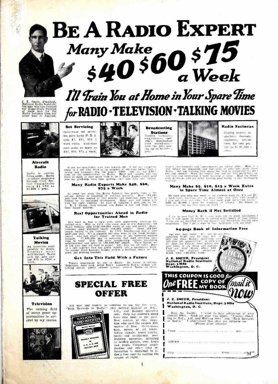
BE A RADIO EXPERT Many Make $ /J5
$4O'0 a week Í!l TaioYou atflomein3'nr Spare ̀ Iune
JorRADIO TELEVISION'TAIKING MOVIES J. E. Smith President, National Radio Institute the man who has directed the Rome -Study training of more men for the Radio Industry than any other man in America.
Aircraft Radio
Radio is making flying safer. Radio operatore employed through Civil Ser- vice Commission earn $1,620 to $2,800 a year.
Talking Movies
An invention made possible by Radio. Employs ninny well- trained Radio men for jobs pay- ing $75 to $200 a
Television The coming field of many great op- portunities is cov- ered by my course.
Set Servicing Spare -time set servie - ing pays many N. R. I.
men $5, $10, $15 a
week extra. Full -time men itiake as much its
$40. $60. $., a week.
Broadcasting Stations
I:utpl p ut:unI_r.. engineers, oper- ators, installation a n ntainten:utee Wren foi' jobs pay - !ng lip to $S,(Ou a
If you are dissatisfied with your present job; if you are at niggling along in a rut with little or no prospect of anything better than a
shinny pay envelope --clip the coupon Nti \ \'. Get my big FRE;I, book on the opportunities in Radio. head how quickly you can learn at home in your spare time to be a Radio Expert -what good jobs my graduates have been getting -real jobs with real futures.
Many Radio Experts Make $40, $60, $75 a Week
In about ten years the Radio lndusuy has grown from a few million dollars to hundreds of millions annually. Over 300,000 jobs have been created by this growth, and thousands more will be created by its continued development. Many Wien and young men with the right training -the kind of training I give you in the N. R. I. Course -have stepped into Radio at two and three tries their former salaries.
Real Opportunities Ahead in Radio for Trained Men
It's hard to find a field with more opportunity awaiting the trained man. Why in 1932 -the worst year of the depression -the Radio Industry sold $200,000,000 worth of sets and parts ! Manu- facturers alone employed nearly 100.000 people! About 300.000 people worked in the industry. In 1932, broadcasting had a most profitable year. It's a gigantic business, even in the worst business years! And look what's ahead! Millions of sets becoming obsolete annually. 17,000,000 sets in operation that need servicing from time to time! Over 500 great broadcasting stations furnishing entertainment and news to 100,000,000 people. These figures are so big that they are hard to grasp ! Yet, they are all true ! Here is a new industry that has grown quickly into a commercial giant. No wonder great business leaders predict a brilliant future for this great and growing business.
Get Into This Field With a Future There's opportunity for you in Radio. Its future is certain.
Television, short wave, police Radio. automobile Radio, midget sets, talking movies, public address systems. aircraft Radio -in every
SPECIAL FREE OFFER
Act now and receive in "Rich Rewards in Radio,"
addition to my big free In.,' this Service Manual on Ir.
A.C., and Battery operated sets. Only my students could have this book in the past. Now readers of this maga- zine who mail the coupon will receive it free. Overcoming hunt, noises of all kinds. fading signals, broad tuning. howls and oscillations, poor distance reception, distorted or muffled signals, poor Audio and Radio Frequency ampli- fication and other vital in- formation is contained in it. Get a free copy by mailing the coupon at right.
i
Radio Factories Employ testers, in-
-. foremen, foremen, service
oion. fer jobs pay - ing Itp to $7,5110 a
year.
branch, development, and improvements ,ue taking place. Here is a real future for thousands and thousands of men who really know Radio. Get the training that opens the road to responsibility. gnud pay and success ! Send the coupon now and get full particulars un how easy and interesting I make learning at home. Read the letters front graduates who are today earning good money in this fascinating indu,U y.
Many Make SS, $10, $15 a Week Extra in Spare Time Almost at Once
Ily book al. ills Rota mtuiv o i sty -indents made $.,, $10 and $15 a week extr.i -'rrieing sets iii se.ne time. soon after they enrolled. I give you pl:ns and ideas that hair snide good spare -tithe money - $200 to $1,000 a year -for hundreds of fellows. My course is famous as -the one that L >- fer it .,It'
Money Back if Not Satisfied I am so sure that N. R. 1. can train you at home satisfactorily
that I will agree in writing to refund t ttry penny of your tuition if ' are net satisfied with my Lessor I. -met ion Service upon cm 1 Inn. You'li get a tohv f Ili', I '',i with ute hoop.
64 -page Book of Information Free Get your copy today. Its free to any -
ambitious fellow over 15 years old. It tells you about Radio's spare -time and full -tine job opportunities; it tells you all about my Course ; what others wlei have taken it are doing and making Find out what Radio offers Y(tl' without the slightest -litigation. MAIL THE (Yr1l'ON Now
J. E. SMITH, President National Radio Institute Dept. 3 MS8 Washington, D. C.
MI MIN - J. E. SMITH, President National Radio Institute, Dept. 3 MS8 Washington, D. C.
]rear Mr. Smith : I want to take advantage of your se.'.ial Offer. Send nie your two books, "Trouble Shoot - inic in D.C., A.C. and Battery Sets'' and "Rich Reward. m Radio." I understand this does not obligate tute.
(Picase print plainly)
I ddrcss
City
Age. .
.State
SHORT WAVE RADIO devoted to short -wave transmission and reception in all their phases
November, 1933 Vol. 1, No. 1
IN THIS ISSUE :
By Way of Introduction
The Triflex -A 1 -Tube Reflex by Clifford E. Denton
Capt. Hall Tells How to Identify Foreign Stations by Capt. H. L. Hall 10
Short Wave Short Cuts
Building and Operating the Convertible 5
by Robert Hertzberg 14
The Maligned Modulator by Robert S. Kruse 20
Why Skip Distances? 21
Stations of the U. S. S. R 23
Satisfactory Short -Wave Reception by Arthur H. Lynch
Notice to Contributors
Bringing the S. W. Receiver Up to Date.
Naval Time -Signal Schedule
Chart of Radio Symbols
The Denton Trophy Contest
Short -Wave Station List
The Before Breakfast Short Wave Club ... .
How to Get Started on 5 -Meter Work by Arthur Hertzberg
Not the "How" but the "Why" of Super - heterodynes by L. van der Mel
13
24
26
27
30
31
32
33
36
38
41
2
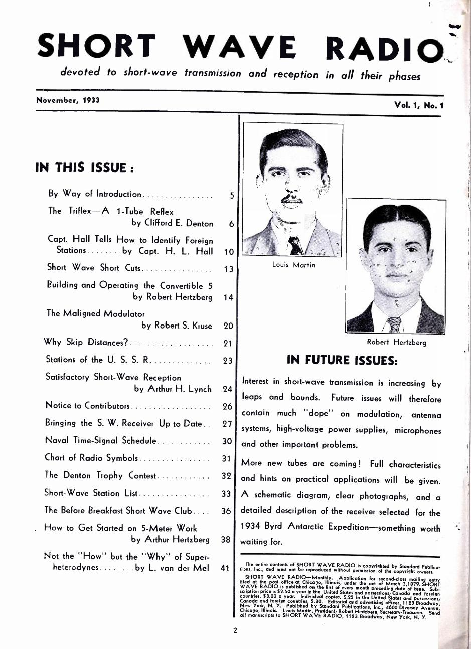
Louis Martin
Robert Hertzberg
IN FUTURE ISSUES:
Interest in short -wave transmission is increasing by
leaps and bounds. Future issues will therefore
contain much "dope" on modulation, antenna
systems, high -voltage power supplies, microphones
and other important problems.
More new tubes are coming ! Full characteristics
and hints on practical applications will be given.
A schematic diagram, clear photographs, and a
detailed description of the receiver selected for the
1934 Byrd Antarctic Expedition -something worth
waiting for.
The entire contents of SHORT WAVE RADIO is copyrighted by Standard Publica- tiDns, Inc., and must not be reproduced without permission of the copyright owners. SHORT WAVE RADIO -Monthly. Application for second -class mailing entry filed at the post office at Chicago, Illinois, under the act of March 3,1 879. SHORT WAVE RADIO is published on the first of every month preceding date of issue. Sub- scription price is $2.50 a year in the United States and possessions; Canada and foreign countries, $3.00 a year. Individual copies, $.25 in the United States and possessicns; Canada and foreign countries $.30. Editorial and advertising offices, 1123 Broadway, New York, N. Y. Published by Standard Publications, Inc., 4600 Diversey Avenue, Chicago, Illinois. Louis Martin, President; Robert Hertzberg, Secretary- Treasurer, Send all manuscripts to SHORT WAVE RADIO, 1123 Broadway, New York, N. Y.
.Ship aboard a
SCOTT ALLVf/AVE DEeirav fora THRILL CRUISE 'ROUND THE
WORLD
If you're an adventurer at heart (and aren't we all ?) you'll glory in the thrills of cruising the ether -waves via a SCOTT ALL -WAVE Deluxe Radio.
Sit right in your own comfortable living room ... there's no sea -bag to pack, no dun- nage to stow, no passports to secure. Just the twist of a single, simple tuning dial and it's "Ho! You're off for strange lands of romance and allure!"
Supreme for Stay -at -Home Listeners First a shakedown cruise in home waters. Listen in
on American broadcast stations near and far -coast - to -coast is an easy jaunt. Discover the marvelous capability of this dream ship to carry you anywhere at your will ... with a delightful fidelity of tone that puts you right into the sending studio, giving you every word of speech and every note of music with a glorious perfection that transcends all previous heights of mechanical sound reproduction. Your own ears will tell you so ... and the evidence is backed up by scientific laboratory findings that prove SCOTT radio reproduc- tion to be the closest to perfection yet attained.
As a first venture in short wave reception listen -in on the crime wave as reported by police calls from one end of the land to the other . .. eavesdrop on gossipy amateur wireless telephony "hams ", and hear the air- planes and their ground stations talk back and forth.
Hear Canada and Mexico Now venture farther! Roam the air -waves to Canada
and Mexico. Hear something different ... something typical of these near -by foreign lands broadcast on wave bands from 15 to 550 meters. Don't fret about the rumors you may have heard that these countries are soon to change wave -lengths ... your SCOTT can be equipped to receive on all bands between 15 and 4,000 meters at a small extra charge.
Listen -in On All of Europe And now you've "got the feel of your ship." Head
out into the open ... start on a fascinating explora- tion cruise for radio joys that are new and different.
Here's England, first! GSB, at Daventry, is sending out the news of the day for the benefit of Colonial
. -
..440500110146- listeners-in . there's peppy music from a famous London hotel . .. and at signing off time (midnight in London, but only 6 P.M. Central Standard Time) the chimes of Big Ben. atop the Houses of Parl'ament, clang sonorously as though you were actually there to hear them in person.
Slip your moorings once again. Cross the Channel and lend an ear to Radio Colonial. Pontoise. France. It's bringing you Parisian music and typically French entertainment.
Varied Programs from Far Countries Distance still lures your Then set your course for
Germany ... in a jiffy you're listening to Zecsen, with programs of glorious symphony orchestras, and per- haps a speech by "Handsome Adolph" that will give you a different viewpoint on Hitlerism.
Make port at Madrid, in sunny Spain, and hear EAQ broadcasting typical National music. Announce- ments from this station are considerately made in English as well as Spanish.
Then swing south to Rome and hear the voice of 12RO's woman announcer tell you its "Radio Roma, Napoli," that's on the air. Most likely the following musical program will be opera direct from LaScala, in Milan, or some other musical treat worth going actual miles to hear -and you'll be listening to it, with purity of tone and richness of reproduction that's truly amazing, without stirring from your easy chair at home.
And now for an adventure -trek that holds a supreme "kick" for the radio sensation -seeker! Sail away "down under." Listen in to VK2ME or VK3ME, in Sydney and Melbourne, Australia. Hear the call of that famous Kookaburra bird, listen with delight to an interesting and varied program of music and talks on the commer- cial and scenic attractions of the Antipodes.
Owners' Reports Show Real Ability And these are but a few of the interesting places to
be visited by means of your SCOTT ALL -WAVE Deluxe Receiver ... F. L. Stitzinger, for instance, is a Scott owner who in a six -month's period received 1588 programs from 41 stations in 22 foreign lands. A. G. Luoma got 1261 programs from 75 different stations in 26 countries, and some 200 other SCOTT owners repotted reception of 16,439 programs from 320 sta- tions in 46 countries during the same time.
"Can such startling radio performance be true ?"
3
you ask. Do you doubt that any hut radio professional' can enjoy the delights of exploring the air -waves ti., world over, far from the too -familiar programs of broadcast stations here nt home? Do you think th..t .t
may be possible, but feel that the cost of sulfic,cr.tl: able equipment is more than you can afford for enter tainmentf .
New Value at Moderate Cost! Then set your mind at case! For such performance is
actually possible ...we gladly prove it to you, and Is... k
the proof by an iron -clad guarantee of consistent foreign reception.
Laboratory technique, employing the world's most skillful, specially trained engineers and craftsmen in custom -building a receiver constructed to the htgher standards of perfection known in radio, makes poss.hlr the super -performance of the SCOTT ALLWA Deluxe for any radio -user, regardless of his expericn. e
or skill in operating. In this set top efficiency is couplc.l with absolute simplicity of tuning.
Prohibitively high priced? Not at all! You can h:.se a SCOTT, and enjoy the supreme thrill of mastering the air -waves of all the world, at moderate cost.
Get Complete Details-Mail Coupon! Because the SCOTT ALL -WAVE Deluxe is one of
the truly fine things of the world, custom -built for those discriminating people who demand the best, it is not distributed broadcast, to he casually picked up here, there, or anywhere. To get full particulars re- garding it, absolute PROOF of its performance, and all the information you require, simply send the coupon below direct to the modern scientific laboratories where it is built.
E. H. SCOTT RADIO LABORATORIES, I: .C. 4450 Ravenswood Ave., Dcp't SWR -! 1.3 , III.
Tell me how 1 can have a SCOTT ALL -WAVE Deluxe to take me radio world -cruising. Include all tech- nical details, proofs of performance, and complete information.
Name
Address
City State

Don't Let Him Get FAT
On YOUR Time! 11'll 100u 1?a1 10111 0u1 of 1Our %4r% 11111Soiue.t
The proper kind of service information will kill that animal. Rider's Manuals give you the service information which will bearish waste and loss of time during service operations. No longer is it necessary to hunt -guess- experiment and hope that you are right. Hurting and guessing cost you money.
Sets with whiskers are as easily serviced as the very new ones. Nothing is a secret in a commercial receiver when you own Rider's Manuals. Upside -down servicing (chassis turned upside- down i is as easy as you want it to be. You dont have to be a Sherlock Holmes when you have these Manuals because the hard -to -get and seldom- heard -of circuits which cause so much trouble for the service field are in these Manuals.
No more guessing at peak frequencies -or hunting for trim. ncrs and tracing of power transformer leads. All of this material i- in the !Manuals. No more wishing you had the circuits. They ARE there! Right in the Manuals. You don't have to gaze into a crystal ball to learn w hat units are in sealed cans and the circuit. Tbis information is shown in Rider's Manuals.
Banish waste and loss of time! Make every minute on the job a paving minute. Get Riders Manuals- -they will pay for themselves man) limes over.
The fact that these Manuals are the finest in every respect and will be of tremendous aid is proved by their use and recom- mendation by such famous tube companies as RCA Radiotron, E. T. Cunningham, Inc., National Union Radio Corp. such famous instrument ,manufacturers as Weston, Hickok, Readrite, etc.. and such famous set manufacturers as Strontbcrg- Carlson, Iada, A11- American, Grigsby- Grunou', etc.
Rider's Manuals, Volumes I, II and III cover receiver pro- duction from 1919 right up to the minute. Volume 111 contains the receivers produced during the last year, inclusive of about .tune, 1933. Volume Il contains the earlier productions. Volume I contains the receivers from 1919 to about May, 1931. ABSO- LUTELY NO DUPLICATION OF CONTENTS IN THESE MANUALS!
Volume
Start your Rider's Manual library today. Each volume is self - contained and does not duplicate. Each has a complete index. Each is available with a money -back guarantee!
A NEW Rider MANUAL
Specialized Auto Radio 3aanual
Volume 1
Loose leaf * About 300 pages * Up To The Minute Here is a specialized Auto Radio Manual which contains all
auto radio receivers -old and new -for the auto radio specialist. This manual has no equll It contains more pages than
any other auto radio manual. . It contains more receiver schematics than any other auto radio manual. . . . It contains more information -old and new -than any other manual.
Rider's Specialized Auto Radio Manual -the Rider Manual in the brown cover- contains the very latest auto radio receivers and the old ones too. It contains schematics- chassis layouts - voltage data- resistor data -electrical values- point-to -point data -socket layouts -installation data- antenna data. Everything you need.
Price $3.50 Postpaid Get Your Copy Today! Sold With a Money
Back Guarantee!
Perpetual Trouble Shooter's Manual I, $7.50
'Volume I Volu11114 II volatile III Specialized
:1110 !Radio Mani Name
Volume II, $6.00 Volume III, $7.50 - C O KJ Y O N - - - --
JloIIII F. hitter, 1440 Broadway, New York, N. Y. Enclosed you will find $ for which you will send at once postpaid .... Volume I .... Volume II .... Volume III of Rider's Perpetual Trouble Shooter's Manual .... Spe- cialized Auto Radio Manual. If I am not satisfied, and return the manual within 10 days after receipt and in perfect condition, you will immediately refund my money.
Address
City State
L _ 1
4

SHORT WAVE RADIO devoted to short -wave transmission and reception in all their phases
Robert Hertzberg, Editor
November, 1933
Louis Martin, B.S., Technical Director
General Advertising and Editorial Offices, 1123 Broadway, New York, N. Y.
Vol. 1, No. 1
By Way of Introduction
.HAT, another magazine? Yes, another one; but this magazine
is designed to cover a specific field for a specific group of readers. In short, this magazine is for the short- wave listener and, of course, will feature short -wave apparatus. We say apparatus because we do not mean receivers alone; we intend to run anything whose field of applica- tion lies below 200 meters.
It may be news for some people to know that there are about 70,000 short -wave fans aside from the transmitting hams, and that the thirst of these 70,000 people must be quenched. It is the purpose of this magazine to do the quenching.
We believe we are qualified to know what you want and must have. Robert Hertzberg, associated with radio since the old spark days, formerly managing editor of RADIO NEWS and RADIO DESIGN, and asso- ciate editor of RADIO -CRAFT and SHORT WAVE CRAFT, is probably bet- ter qualified to realize the needs of short -wave listeners than any one else in the field. Louis Martin, for- merly managing editor of RADIO CRAFT, and a man of rigid technical morals, will see to it that the appa- ratus run in this magazine are as good in actuality as they sound on paper. We want to go on record right here and declare that no re- ceivers will be described that have not passed a satisfactory test by the editors.
ASIDE from the short -wave articles, we will also publish
considerable material on the ultra - short- waves. We firmly believe that the very short waves will be the resting place for television when it finally peeps around that mysteri- ous corner. Our readers will be kept well supplied with information along these lines.
Because of the simplicity of ultra- high- frequency apparatus, it is our intention, also, to print information on small transmitters suitable for
5
these bands. There is a very fruit- ful field for the experimenter here, as contrasted with the relatively well -explored low -frequency chan- nels.
The five -meter band, for instance, is suitable as "meat" for the short- wave fan. Super -regeneration is used in this band almost to the ex- clusion of all other circuits ; it is our intention, under these condi- tions, to give a comprehensive de- scription of super -regeneration in an early issue in order to strengthen the requirements for successful op- eration of such circuits in the minds of our readers.
OUR policy, both editorial and advertising, is simple, and
straightforward. Editorially, we will run whatever the readers de- mand ; the only requirement is that the material must pertain to the short -wave band. As for our adver- tisers, only those who are recognized as representing the highest calibre in the field will be represented. It is not our intention to fill the book with the many gyps which infest the mar- ket. In fact, we welcome and re- quest comments from readers re- garding the service rendered by our advertisers. We are an entirely independent organization with no commercial axe to grind.
IT HIS issue is, necessarily, small. The physical size of the magazine
will increase as new material comes in. We do not believe in publishing a large book and have 50 per cent of it full of plain junk in order to fill it ; we prefer quality to quantity. We feel sure that by the time the third or fourth issue rolls around, the size of SHORT WAVE RADIO will have in- creased materially.
That is our stand. We believe we know what you want and how you want it. If we do our part, we feel sure that you will do yours. If you are ready, then turn over and start right in.

NLW circuits and tricky ap- paratus have always inter- ested radio experimenters. The possibility that nearly
every new circuit will deliver un- believably loud signals when tuned to unbelievably weak stations al- ways persists back in the mind of the dyed -in- the -wool fan. To date, nothing so radical has appeared. New circuits, of course, are always available; but upon detailed inspec- t ion, one usually finds that either the color of the wire has been changed or that a tube has been placed hori- zontally instead of vertically. In plain English, only a radical change in both tube and circuit design can produce results that are radically different from those now secured with standard apparatus.
The reflex receiver heralded some six years ago as the outstanding achievement of the age is with us again. We say "again" for the sim- ple reason that its popularity was only temporary, for it soon was cast into oblivion with hundreds of other sets of like nature. The fundamen- tal concept upon which the popular- ity of the reflex was founded is still a sound one : the high cost of tubes and the necessity for continually recharging batteries made it desir- able to design a circuit in which a single tube replaces the usual two or three tubes. Upon this premise, the reflex was designed. As other ex- perimenters added bits and sub- tracted bits from the original circuit, new features, some surprisingly in- consistent, were credited to the re- flex. Then, as new tubes were manu- factured, and as the prices of these new tubes were reduced, the neces- sity for having one tube do the work of two or three was removed, and, consequently, the reflex faded out.
During the past year or so, en- gineers have again turned their at-
6
t.
The TRIFLEk A 1 -Tube Reflex
THE TRIFLEX: Here is a really good article describing a really novel short -wave receiver. Sensitive short -wave sets have been described many times in the past; our aim now is to pre- sent a one -tube receiver with greater sensi- tivity titan is usually obtained in one -tube sets. We believe Mr. Denton has made good. The "Trifler" uses a single 6F7 tube in a unique re- flex arrangement that promises to be one of the best possible. Regeneration in one section of the tube further increases the sensitivity.
Tests made in our own laboratories con- vinced us that the "Trifler" is about the best single -tube receiver that we ever listened to.
By Clifford E. Denton Well -known short -wave engineer, who has probably developed more short- wave equipment for the experimenter
than any other man.
tention to the reflex receiver, but this time with a little different thought in mind: small space and economy of operation are now gen- erally conceded to be the only out- standing advantages of the reflex. Here is where the commercial en- gineer stops and where the amateur begins. Everyone who has followed the new tube announcements during the past year and a half has prob- ably come to the conclusion that these new tubes are too complex for all but the well -groomed scientist. Tubes with seven grids, tubes with two and three plates, tubes with their elements placed in somewhat mystical and confusing positions, are thrust at the unsuspecting, and
usually placid, public with such speed that it will probably be years before the amateur experimenter familiarizes himself with all of their working characteristics.
The "Triflex"
Out of this confusion the writer picked the 6F7 as the basis of a one - tube receiver connected in a reflex arrangement of such stability as to astound all those who have listened to this little set perform. Now, we do not wish to point out that this is the circuit. We do not wish state that this receiver can pro- duce unbelievably loud signals when tuned to an unbelievably weak sta- tion. We do say, though, that this one tube can be connected to act as an r.f amplifier, a regenerative detector, and as an audio -frequency amplifier, and that this circuit has out -performed, both as regard sen- sitivity and volume, any other one - tube set yet heard by the writer.
The reflex circuit is a bit tricky if you do not know what makes the wheels go round, so we are going to start off on the right foot and give an elementary discussion of not only what makes the wheels go round, but what makes the signals go round. The little sketch of Fig. 1
tells the story graphically. By fol- lowing the arrows, you see that the signal from the station is fed to an r.f. amplifier (untuned in our case), then to a tuned detector (which is regenerative), out from the tuned detector back into the untuned r.f. amplifier to the phones or loud- speaker. In the diagram, the solid lines represent r.f. energy and the dash lines audio energy. The fun- damental operation of the receiver is simple : all signals picked up by the antenna are amplified by the un- tuned r.f. amplifier; the output is
SHORT WAVE RADIO

Jnunuuunununnuuuuanununnuunuuunuruanuunuounnunnunnnnnnnomuunnnuounnunnuuunnnnnuunnunmm11nuunnnnnnnununununnnannr-
SUMMARY: This article treats in detail the theory, operation and construction of a single tube reflex receiver called "The Trifiex." The reflex receiver had its day about five or six years ago; but, be- cause of the inefficiency of tubes in use at that time, and because of the comparatively low cost of apparatus, it was discarded in favor of the more stable and complex, straight, tuned r.f. set.
The reflex is here again; the new tubes have revived it. The modern reflex is not the conglomeration of tricky circuits that made every builder turn grey over night; with a little care it can be made to perform the function of three tubes in one with perfect stability.
f. The "Triflex," as the name implies, is a 1 -tube reflex performing - three operations at the same time, and uses the new 6F7 tube, a com-
- bination triode and pentode, in a circuit that is easy to build and that really works. Read the article by Mr. Denton and convince yourself.
E.
............... i l................1......... n............ m...... 1............... ...1........................... n........l..l... n......l...I I I I I I..l. m...... n. .... III......... .........................I....,
then fed to the tuned detector, which selects the desired signal by means of a tuned circuit; the output of the detector, which is audio, is fed back again to the untuned r.f. amplifier, which now acts as an audio ampli- fier, to the phones. Thus, if all of these functions were performed by a single tube, we would have three operations: untuned r.f. amplifica- tion, detection, and a.f. amplification. The Trifiex does perform these func- tions -hence its name.
How the "Trifiex" Works
How these functions can be per- formed in one tube can only be ap- preciated after a study of the in- ternal construction of the tube it- self. A drawing which mechanically shows the arrangements of the ele- ments is shown in Fig. 2. The tube is seen to be composed of two sep- arate and distinct sections, an upper section and a lower section. The lower, or first, section is a simple. ordinary, garden -variety of triode, similar in construction to the 27 type tube with which we are all familiar. The upper section is a simple pen- tode, similar in construction to the 47, 58, 57, etc. The heater and the cathode of this tube are common to both sectións. In other words, one cathode serves both the triode and pentode sections of the 6F7. Other than this, the elements are distinctly separated, as seen from the tube - prong connections shown in the lower part of the sketch. It is easy to see, therefore, why we can take a signal from the antenna, feed it into the pentode section, amplify it, then feed it into the triode section, where it is detected, and, finally, again connect it to the pentode sec- tion, as shown in the block diagram of Fig. 1.
The development of the circuit, therefore, merely consists in de- veloping individual units, and inter- connecting them so as to give the desired results. Let us first develop -our pentode circuit, then our triode circuit, and then interconnect the two.
Figure 3 is a simple r.f. amplifier used extensively in short -wave work. The condcu ' r Cl is a small variable
for NOVEMBER, 1933
unit connected in series with the an- tenna when the No. 1 antenna post. intended for long antennas, is used. If a short antenna is used, then it should be connected to post No. 2. R.F.C., connected between post 2 and ground, is a standard radio -fre- quency choke with an inductance of about 21/2 millihenries. Condenser C7 is a bypass condenser for the grid -bias resistor R2. One end of R.F.C. connects to the control grid of the tube, the screen grid goes to B plus 100 volts, the suppressor grid connects internally to the cathode. and the plate connects to the primary of the r.f. transformer labeled L. There is nothing com- plicated or mystifying about this connection. It is perfectly stable in operation and should be very easy for any constructor to build.
Our triode section shown in Fig 4 is a simple, three- circuit arrange- ment, familiar to all short -wave fans. Several unique characteristics of this circuit set it apart from the more conventional arrangements. The coil L is the same coil L used with reference to Fig. 3, so that now we see that the output of the pentode section connects to the input of the triode section by means of L; con- denser C6 is the tuning unit ; R.t and C4 are the conventional grid - leak and condenser combination ; C5 is the small r.f. bypass condenser ;
R.F'.C. of course, is an r.f. choke, similar to that used in the antenna circuit; condensers C2 and C3 are bypass units whose function will be explained shortly. Now, putting the whole circuit together, we have
TICKLER CS
C4 L
Ae R.F.C.
C6 R3 RI- ti
A.F.T.
B+ B- IOO VOLTS
C3
FIG. 4 -THE TRIODE SECTION. Here is the output section of the tube, which, in turn, again feeds the input.
PANEL VIEW OF THE "TRIFLEX." Left to right: antenna condenser, tun- ing condenser, and regeneration control.
SIGNAL
SIGNAL
AJJ -- + I
RF
R.F.
A
UNTUNED RF
AMPLIFIER
TUNEO DETECTOR
t
t PHONES
I 11 L_4---4__ ___- ---t-- -t-J
.Ert
FIG. I -BLOCK DIAGRAM OF THE "TRI FLEX."
The solid line corresponds to r.f. and the dotted lines to audio signals.
CONTROL GRID CAP
(PENTODE SECTION)
SUPPRESSOR GRID
[PENTODE SECTION)
I /7 I ¡, I\ LI1 H
I' PLATE
K n PZ (PENTODE SECTION)
GRID Gi P1 SCREEN GRID (TRIODE PLATE ( PENTODE SECTION) (TRIODE SECTION)
,SECTION) S.G.
PZ
SCREEN GRID
I( PENTODE
SECTION)
PI
`- G1
Ere
FIG. 2 -THE 6F7 TUBE. This diagram shows internal construc- tion and prong connections of the 6F7.
A BAIT. - 6 VOLTS
a+ 100 VOLTS
E..
FIG. 3 -THE PENTODE SECTION. Illustrating the input connections of
the "Trifiex." This is not reflexed.
7

PHOTOGRAPH OF THE UNDER SECTION OF THE "TRIFLEX."
Fi!r. 5, which we will examine in detail.
The antenna connects through condenser Cl to the choke, and from the choke to the control grid of the pentode section of the 6F7. The ether end of the choke connects to the secondary of the a.f. transformer which is shunted by condenser C3. Note particularly that the cathode of the 6F7 connects to ground
through R2 and C7, and that one end of C3 connects to ground. Since C3 is of such size as to offer little reactance to the flow of the very high -frequency currents used in short -wave work, the lower end of the antenna choke connects to R2 through C3, as far as the r.f. signal is concerned. We will come back to this unit a little later. The plate of the 6F7 connects through the
primary, P, of r.f. coil L, then through a pair of phones, or loud- speaker, to B plus 100. The sec- ondary of L is tuned by CG, and fed to the grid of the triode section. The plate of the triode section connects through the tickler and an r.f. choke to the primary of an a.f. transform- er, the secondary of which connects to the antenna choke.
The signal, after being amplified by the pentode section, is still r.f., and since condenser C8 is connected directly across the phones, it by- passes this r.f., and conditions are exactly the same as if the phones were not present. The voltage in- duced in the secondary, S, by the primary actuates the grid of the triode section, which rectifies the signal and feeds it through the primary of A.F.T. Condenser C2 across the primary is used for the purpose of bypassing any r.f. that may remain in the triode plate cir- cuit. The audio voltage now across the secondary is fed back to the pen- tode, where it is amplified again, and passes through the primary of L until it reaches the phones. Since this signal is now audio, coil P, which is extremely small, can have little effect on it ; likewise condenser C8, having only a small reactance to a.f., is not affected, so that the sig- nal is heard in the phones.
If condensers C2 and C3 were too large, some of the audio would be bypassed ; particularly if C3 is too small, we would lose r.f. signal strength because some of it would have to go through the secondary of A.F.T. If condenser C8 were too small, some of the r.f. would have to go through the phones, and again we would lose signal strength; on the other hand, if it were too large,
N LO
BACK
-GND STRIP
-v- e OP -L
PHONES
I" u z --- - -- Z 3..
2 B Ib Ib Ib' Ib 16
COIL SOCKET
4
CI
0110 (V
Illu_
I'D BATTERY
I4oD
_,"2ii 32'__
C -I" a
- i
CABLE SOCKET ° 6>
BEND DOW N
ON DOTTED LINE
=i-t m .. Z !" o ï
z LJ------? - 5"
-e- FRONT
8'
CHASSIS
BEND UP ON DOTTED
LINE
4"
CUT-OUT FOR DIAL
8"
FRONT PANEL
8
COMPLETE MECHANICAL DRAWING OF THE CHASSIS AND PANEL OF THE "TRIFLEX."
SHORT WAVE RADIO

L
we would lose some of our audio signal. Thus, we see that the values of capacities used in the "Triflex" are fairly critical, and must not be deviated from by more than about 50 per cent.
Various views of the receiver are shown in the photographs and in the pictorial diagram shown here. The front view of the set shows three knobs, whose functions are as fol- lows : lower left, antenna condenser C1; center, main tuning dial for C6; lower right, regeneration control R1. The panel is made of 1/16 inch aluminum, 8 inches wide and 61/2 inches high. The subpanel upon which the apparatus is mounted is 8 inches wide, 61/2 inches deep and 2 inches high. The locations of the various parts are marked on the photographs. The rear view of the receiver shows the location of the 6F7 tube, the tuning condenser C6, the plug -in coil; the audio -frequency transformer, the plug -in socket used to feed the A and B supply to the set, the antenna -ground binding post strip, and the phone terminals. The underview shows the location of all the incidental parts used in the con- struction other than those men- tioned. These parts are labeled for convenience.
The first step in constructing the receiver is to lay out the panel and base as per the detailed drawings given herewith. The sizes of all holes are marked, and the only diffi-
(Con.tinued on page 47)
ci b RFC E
A FT
C3
3
SUPPRESSOR GRID (INTERNALLY CONNECTED)
DZ 6F7
CONTROL GRIO , (CAP)
C7
PI- ;R
R2' _
H
/ SCREEN GRID P' ( Q (PENTODE ¡ SECTION)
f 00 \ VVVVV\ s,,y Cd
T
GRID (TRIODE SECTION)
RFC
ç
R3r
G
MO VOLTS
8 9r
A BAIT 6 VOLTS
fit 9
FIG. 5- SCHEMATIC CIRCUIT OF THE ONE -TUBE "TRI FLEX."
The complete list of parts for this set is listed below.
CI -About 35 mmf. variable, with insulation washers (Acratest).
C2 -I mf. bypass (Flechtheim G.F. 100). C3 -.001 mf. mica condenser ( Acratest). C4 -.000I mf. mica condenser (Acratest). C5- .00025 mf. mica condenser (Acratest). C6- .000I5 mf. variable ( Acratest No. 6854). C7 -.I mf. 200 -volt tubular condenser
Flechtheim ). C8 -.001 mf. m ;ca condenser ( Acratest). RI- 50,000 -ohm potentiometer ( Frost). R2- 350 -ohm, 1/2 -watt resistor. R3 -3 megohm, 1/2 -watt resistor. R.F.C. -2 r.f. chokes, 21/2 millihenries (Na-
tional, type 100). A.F.T.- audio -frequency
transformer, about 3:1 ratio. I-4 -prong wafer socket for battery cable. I --6 -prong wafer socket for coil L. I -7 -prong small wafer socket for 6F7 tube. I-4- conductor battery cable. I -dial and drive unit (Acratest). I- escutcheon plate for dial (Acratest). I-metal panel and chassis as per data. I -tube grid -clip. 3 -knobs for controls (see photographs). I -tube shield. I- triple binding -post strip. I -twin phone tip jack. I -set of three- winding plug -in coils to cover
the band from IO to 200 meters (Alden). I -6F7 tube.
r2
R FC.
C3
3 AFT.
GND.
P= H1ToK S = P To H2
T = S.G. To SUPP.
$
SUP P.
R.FC.
^alll I T
P
41111111` 1 = H2
HI
C5
A BATT. 6 VOLTS
w C2 P
R1
r4 O
C8 PHONES af-"
p 5
C6 s.
C4
>- R3
A PICTORIAL VIEW OF THE "TRIFLEX" TO BE USED AS AN AID TO WIRING THE SET.
for NOVEMBER, 1933 9

Capt. Hall Tells Howto Identify Foreign Stations
SUMMARY: Ric,'ldrìrct a short -bare receiver is only half the job; the other half is to listc'1i- in. Part of this second half of the job is covered by the station list; and the last hart is to be covered in this department. Captain Hall, who is to conduct this monthly depa)t- .n ent, is one of the few experienced listeners with a critical ear, an excellent rcc( icing sta- tion, and an enormous log of verified stations.
I ( ìitications from listeners, especially ont- side of New Fork, are especially desirable, and will be published in this magazine with full credit. All verifications will be rctu,ned un- altered.
II'c wish to take this opportunity to thank ('apt. Hall for his excellent c,l(,percttion. in preparing this manuscr,pt, curd fo). his gener- osity in loaning us his original rc rifications for rc production in this issue.
DX-1NG and in particular short -wave I)X- ing -is one of the newer hobbies. How many fans who listen to pro -
grams from distant countries really have any thorough knowledge of for - eign languages? Not many. Realiz- ing this fact, and always trying to please the hard -to- satisfy fan, many foreign stations have adopted a plan by which the newcomer in the short - wave field and the youngest fan can easily tell just what country's broad - cast they are listening to. This very convenient and most satisfactory idea has been so worked out by the individual stations that certain sounds or musical selections are defi- nitely associated with the particular station transmitting them. No two stations use the same identifying signals. When one station broad- casts on several wavelengths, it uses the identifying signal that it adopts on all of them.
Let us go over the "foreign locals" first. «'hen G5SW was England's "best bet," they always broadcast "Big Ben" whenever that world fa- mous clock struck the hour. Now that Daventry has taken the place of' G5SW, they also continue to use Big Ben's booming notes to tell the world that Great Britain is on the air. The announcer saying, "This is London calling the Canadian Zone," is known to all short -wave fans in this part of the world. Also,
IO
THE RECEIVING STATION OF CAPT. H. L. HALL Two National receivers, a good antenna, and a pile of "veries"
make up the "Captain's Bridge."
when this station "shuts up shop." and the announcer, in a tired al- though very effective voice, bids his listeners, "Good- night, everybody." listeners really feel as though they should respond with the same ',hrase. "Rig Ben" has definitely become known as Daventry's identifying signal.
Next we will listen to France. On the outskirts of Paris is located the town of Pontoise from which the French station has taken its name. When the Frenchman want us to know that they are coming on the air, they always play the "Marseil- laise," the hymn dear to the hearts of all Frenchmen. At the beginning and close of all their short -wave broadcasts, Pontoise broadcasts this martial anthem. Following this is a station announcement in which no call letters are given ; but fans are informed that "Radio -Coloniale" is about to begin their broadcast, "Hello, hello, ici Paris, Radio- Colon- iale, 103 Rue de Grenelle."
Drifting further south we run into sunny Spain. Here we can almost tell without waiting for an an- nouncement that the program we are listening to comes from EAQ, Mad- rid. Spain. Their music is very lively and, with a certain amount of imagination, one can almost see black -eyed señoritas singing and swaying to this music. At regular intervals a station announcement is
made both in Spanish and English; and even if the English announce- ment were abandoned, the Spanish one would be very easy to under- stand, as the announcer speaks slow- ly and distinctly- always the same. First, "Ay -ah -coo, Transradio, Ma- drid, Spain," followed by, "E, A, Q, Transradio, Madrid, Spain." At the close of the program, Spain's na- tional anthem is played -a very in- spiring and a very effective identify- ing signal.
If we were tuning on a Sunday we could go still further south to Africa to Rabat, Morocco, owned by the French. Again we run into a foreign language. Between selec- tions which vary from high pitched native music to high -hat orchestral programs, we hear the Frenchman in Rabat -always the same -say, "Radio Rabat dans Maroc," and then comes the tic -tac, tic -tock of a met- ronome.
Let us go back to Germany, where Deutschlandsender's announcer signs off in German, English, and Spanish.
Up until a few months ago Ger- many used a tick of an alarm clock to tell the world it had been listen- ing to Germany transmitting; but now they have decided that chimes playing eight bars from an old Ger- man song are more effective, and that is what the short -wave listeners now hear at the end of their trans- missions.
SHORT WAVE RADIO

Another European country that broadcasts chimes is Russia, which broadcasts midnight chimes from the Kremlin when it is five o'clock here in the States. Denmark, when broadcasting through OXY, tells the world it is midnight there by means of chimes, when we are just deciding that six o'clock is a good time to eat dinner.
A country that sends the gong of a bell into space is SRI at Poznan, Poland. This station broadcasts bells from their City Hall, not at any def- inite hour, however. This station has a lady in a high voice and a gentleman in a deep voice who an- nounce in this very clear fashion, "Hello, Hello, Polski Radjo- Poznan." This is spoken in Polish and French. Note that the call letters are also omitted. Previous to this announce- ment comes the identifying signals -a gong beaten for eleven seconds with stop intervals of eight seconds. This station has been heard by many who could not identify it.
Now we go to Italy. The lady with the oh ! so lovely voice, is al- ways there to say, "Radio Roma Na- poli," whenever I2R0 is broadcast- ing. Many a male heart has beaten just a little quicker when she spoke. We can hardly call a lady by so rude a name as an identifying signal, but this female vice has become known as Italy's identifying signal.
We will now go a little further from the city of Rome to Vatican City. When listening to HVJ, you will hear a gruff male voice shout, "Pronto, Pronto, Radio Vaticano" to tell the world they want to be lis- tened to. But if .you hear these "Prontos" calling ships, you will know it is IAC calling to the Italian ships.
"Coo -coo, coo -coo, coo -coo," Oh, we are now listening to Portugal. This active bird must be very hoarse by the end of a broadcast as he coo - coo's between every selection, and the selections are sometimes only a minute long. Long may he "coo," for many a fan has jumped in glee at the sound, as CT1AA in Portugal
Dear E1,.
COMMONWEALTH OF AUSTAAUA.
t e;',0<°,' Ca
...ae...t .1. 261. Jur.., n 9;1.
In reply to your comr...ntcatl.n of to, 6:t tay, 19)2, Steticn YULE is the experic...t.1 h!fh fr,,sency tren.sltttrr statlon or the he search Latoretorl.e n the postueter -O rala
e
s The plant tr of an experimental nature and because of this se haven regular rch,e.ul o operating hour.. ho.t.cr. the transmitter has te.r. used on many occasions c a loos for relaying from
s the studios of the Australian oteonal _Dade, sting Service
transmission. hart been heard in America. ,etle 'fiat aie or bare
2. The plant operates on arious frecuenel,, depending on the nature or the wort in mina tut tonally the transmitter is tuned to 5600 PC.
3. The circuit moonrises a.10 matt- self-oscillating tube coupled to 5 watt seruen 'rid separator stare. Tort tube
T` watt modulated ampltne. icn, in turn, is c u up lei to pow.' amplifier consistiez or teo 250 watt t, tts to sdu parallel. The uta m tl rapattllty of the plant is t.. 01 per
d is Linear. The w
output is coopltd to a 600 0110 trahl.rlon liu ne, rtiea se....lf -east on the r.orirontal dipole.
Captain Horace L. Nall, The 'Taming Pm.,
2e0 Broad.., pew UM eire. 2... e
Yours faithfully.
(h E. A1TT) fo. th. COLS( Engineer.
REPRODUCTION FROM AN ORIGINAL VERIFICATION
This letter verifies the reception of VK3LR by Capt. Hall.
for NOVEMBER, 1933
By Capt. H. L. Hall whose reception is the envy of all
who know him.
is considered rather a difficult catch. The League of Nations, still
"parked" in Geneva. comes on the air once a week on Sunday to broad- cast worldly troubles. The announ- cer says, " Hillo, Hillo, Radio Na- tions" and then announces in French before the French tali., English pre- cedes the English talk, and the same with the Spanish transmissions.
Now that we have covered these two continents, let us skip to Aus- tralia, where the Kook -a -burra bird makes his home. If this native bird, that the Australians jestingly call the Laughing Jackass, has no other use in his home town, his call has been made world famous by being transmitted over VK2ME.
VK3ME has nothing as decidedly original as VK2ME's identifying signal, so they broadcast the 9:00 o'clock chimes in the evening when we here in the States are making up our minds to get up in the morning.
How many times have short -wave fans, when questioned on their abil- ity to tune in numerous stations from foreign countries, alibied them- selves by saying that they have so little time to tune because of their
VK2ME " THE VOICE OF
DARWINciI
,
PER',
business hours being so long that when they arrive home, all the sta- tions worth going after have gone off the air? It has always been a belief held by the writer that the average enthusiastic short -wave fan can, if he wants to, pull in nearly every broadcast station worth hear- ing. Taking into consideration the fact that you have a receiver capable of this, let me tell a few instances of what the working man short -wave fan can get, again, I repeat, if he wannts to.
Anyone who has ever lived or visited the part of town in the West Nineties in Central Park West, New York, realizes what terrible condi- tions a short -wave fan is up against. This section of New York City is honeycombed with seventeen-41,r and higher apartment houses. Just think of all the electrical contrap- tions that the dwellers of these styles of homes use just for plain ordinary living! Electric fans, washing ma- chines, driers and many others too numerous to mention.
Just a step from Central Park West, in a house only four stories high, lives a most interesting gentle- man. His name is Max H. Bass, and to employ an expression new even to myself, he is a "hobbyist."
Short waves have intrigued him so, that, although he has devoted hours of study to all his other hob- bies, he has one of the best collec- tions of verifications that the writer has seen in many a day. His secret of arriving at his short -wave suc- cess is easily understood when one takes into consideration the fact that he does not tune haphazardly, but goes about his short -wave tuning intelligently.
He thoroughly believes in buying the best of anything pertaining to radio. For instance, he would rather deprive himself of some plea- sure and use the cash for an excel- lent dynamic speaker. He has one of the best speakers I have ever heard. Formerly, he used a rather fairly well -built "home- made" re- ceiver; but when he saw that a cer-
AUSTRALIA "
VK2ME SYDNEYp
V ADELAIDE
EAY11EggAo Mtle0UaPI(
0
ee,i o
The laughing notes of the Kooka- burra open and now the A W A. World -wide Broadcasting Service.
I103afer
`.t.:.,.
A. W. A. ON/vns an -1 Operates
;.... , ...ree to Great , . . , . . r.r, . at Eur-.pv
. ,,. , . .. . i ,.il
L.r r, rJc.rh .r . .rmenca, lava ..nJ tie .v
Co.r.r.,i rt , Papua, ti... F i-
hr
Australian t,' C -tn c t. t.rirr Rad-o- Electric Wort-.. ' r -.c T.: nu facture of every tvr1 l , . f I i . n r '- tine equipment and Pal nia cast receivers.
Research and experimental labora- tories.
V./odd-Wide Brodc:istinä .r AMALGAMATED WIRELESS (A/SIA) LTD. AUSTRALIA'S NATIONAL WIRELESS ORGANISATION
A VERIFICATION FROM VK2ME IN AUSTRALIA Rear view of a verification sent to Capt. Hall by VK2ME. Note the Kookaburra.
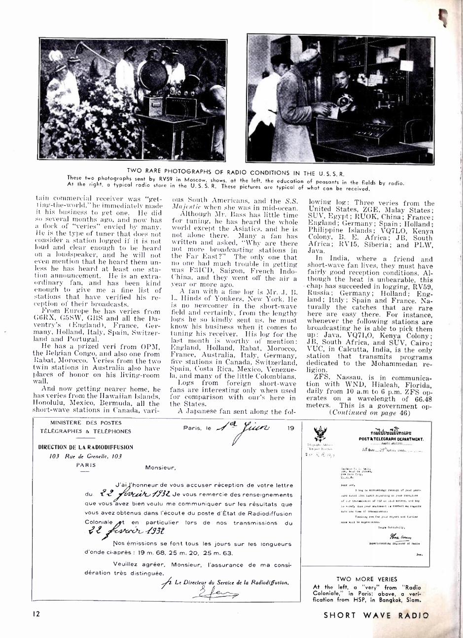
TWO RARE PHOTOGRAPHS OF RADIO CONDITIONS IN THE U. S. S. R. These two photographs sent by RV59 in Moscow, shows, at the left, the education of peasants in the fields At the right, a typical radio store in the U. S. S. R. These pictures are typical of what can be received.
tain commercial receiver was "get- ting- the -world," he immediately made it his business to get one. He did so several months ago, and now has a flock of "veries" envied by many. He is the type of tuner that does not consider a station logged if it is not loud and clear enough to be heard on a loudspeaker, and he will not even mention that he heard them un- less he has heard at least one sta- tion announcement. He is an extra- ordinary fan, and has been kind enough to give me a fine list of stations that have verified his re- ception of their broadcasts.
From Europe he has veries from G6RX, G5SW, GBS and all the Da- ventry's (England), France, Ger- many, Holland, Italy, Spain, Switzer- land and Portugal.
He has a prized veri from OPM, the Belgian Congo, and also one from Rabat, Morocco. Veries from the two twin stations in Australia also have places of honor on his living -room wall.
And now getting nearer home, he has veries from the Hawaiian Islands, Honolulu, Mexico, Bermuda, all the short -wave stations in Canada, vari-
ous South Americans, and the S.S. Majestic when she was in mid -ocean.
Although Mr. Bass has little time for tuning, he has heard the whole world except the Asiatics, and he is not alone there. Many a fan has written and asked, "Why are there not more broadcasting stations in the Far East ?" The only one that no one had much trouble in getting was F3ICD, Saigon, French Indo- ('bina, and they went off the air a year or more ago.
A fan with a fine log is Mr. J. B. L. Hinds of Yonkers, New York. He is no newcomer in the short -wave field and certainly, from the lengthy logs he so kindly sent us, he must know his business when it comes to tuning his receiver. His log for the last month is worthy of mention: England, Holland, Rabat, Morocco, France, Australia, Italy, Germany, five stations in Canada, Switzerland, Spain, Costa Rica, Mexico, Venezue- la, and many of the little Colombians.
Logs from foreign short -wave fans are interesting only when used for comparison with our's here in the States.
A Japanese fan sent along the fol-
by radio.
lowing log: Three veries from the United States, ZGE, Malay States; SUV, Egypt; RUOK, China; France; England ; Germany ; Spain ; Holland; Philippine Islands ; VQ7LO, Kenya Colony, B. E. Africa; JB, South Africa; RV15, Siberia; and PLW, Java.
In India, where a friend and short -wave fan lives, they must have fairly good reception conditions. Al- though the heat is unbearable, this
- chap has succeeded in logging, RV59, Russia ; Germany ; Holland ; Eng- land; Italy; Spain and France. Na- turally the catches that are rare here are easy there. For instance, whenever the following stations are broadcasting he is able to pick them up: Java, VQ7I.,O, Kenya Colony; JB, South Africa, and SUV, Cairo; VUC, in Calcutta, India, is the only station that transmits programs dedicated to the Mohammedan re- ligion.
ZFS, Nassau, is in communica- tion with WND, Hialeah, Florida, daily from 10 a.m to 6 p.m. ZFS op- erates on a wavelength of 66.48 meters. This is a government op-
(Continued on page 46) MINISTERE DES POSTES
TELEGRAPHES & TELEPHONES
DIRECTION DE LA RADIODIFFUSION
103 Rue de Grenelle, 103
PARIS Monsieur,
19
9 J'ai 'honneur de vous accuser réception de votre lettre
du. i .J 4.2,ficeik, /..9.ÌL Je vous remercie des renseignements que vous avez bien voulu me communiquer sur les résultats que vous avez obtenus dans l'écoute du poste d'État de Radiodiffusion Coloniale t en particulier lors de nos transmissions du
17¿ J93 Nos émissions se font tous les jours sur les longueurs
d'onde ci -après : 19 m. 68, 25 m. 20, 25 m. 63.
Veuillez agréer, Monsieur, l'assurance de ma consi- dération très distinguée.
Le Directeur du Service de la Radiodiffusion. / Q
Tele.qraplur .4ddi,
..7.,drp1.1 Dan';AuA
;N° /3fy
n 57!kiat »uJ I,419Ia4I
POSTIITELEGRAPH DEPARTMENT. nwxa.a,TZVe
is Date _ -?.`1 .trab 19A5.__ _ _ _.
Captltn N. L. yoll, 104. vcut 84 ,trO.t,
Nom York City,
Dear ,1r. I bog to acknowledge recalpt of your Pont.
cari 10004 10tH Layne reporting on your recoptlon
of our trunau.alon of P.SP on 14.9 motr.a. und »cg
to nr.ty that your atotem,nt ,S aorrott a. rogurd Cule 004 tan. of tranwlaalan.
Yao.kang you SOS your report und turtaer
one. .»ii Io aypiac lo tti.
Your. fai111x011>.
/I'r.l
Saperint.nd1n6 Ranimer of Rouie
A..
12
TWO MORE VERTES
At the left, a "very" from "Radio Coloniale," in Paris; above, a veri- fication from HSP, in Bangkok, Siam.
SHORT WAVE RADIO

Short Wave Short Cuts Using Tube Base
THE bases of burned ibes make ideal forms for rave
plug -in coils. The main to remove the glass bull he "works" inside the base _et ting glass spattered ;iL the house. It is neither ntl nor necessary to heat the to!. -en the base. Simply wrap Ice of cloth and hit it a stew- ith a hammer. The bulb y' !1',
but the stem and cone es will remain. Dig thee: l a screw driver, cut the es, and blow the holes in t!an by first heating them i cue and whipping the bast you in a quick motion.
When soldering nev ns to the pins, use only a s
I
on each, and shave otl with a knife so that t; l.. not stick in the socket.
nl
Just heat and whip
111I11111111I1IIIIII1I11111111111111IIIIIIII111111II I1111II IIIIII111111IIIII11111I1IIIIIIIIIIIII1111IIII
Money for Your Ideas Every radio experimenter
runs across handy little kinks that save time, trouble, effort, and money. For the best short cut submitted each month, we will pay $5.00. Other pub- lished kinks will be paid for at the rate of $1.00 each.
Keep your descriptions with - in 100 or 150. words in length, typewritten or written in ink on one side of the paper. Put your rough sketches on sepa- rate sheets, with your full name and address clearly indi- cated. Mail all contributions to the Short Cut Department, SHORT WAVE RADIO, 1123 Broadway, New York, N. Y.
l l -.111II11111IIIIIIIII111111I11111111111IIIIIIIIIIIIIIIIII111II111IIIIIIIIIIIIIIII11111111111111111111111IIr
Efficient Lead -in In trs THE increasing popular
blet antennae using r
wire lead -ins has serve1i size the fact that most fans pay little attention od of bringing the le. through the window. A can be snaked through two wires, whose spacin- maintained evenly, requ i
ter arrangement. A very simple, cheap.
lead -in insulator can be two ordinary porcelain which cost only about a Drill a one -inch hole thr: ii
fitted under the window.
SECTIONAL VIEW
NUTS
sed- ha- lve -th-
1
Ord
the
STAND-OFF
INSULATOR / WINDOW
BOARD
This idea saves many an
for NOVEMBER, 1 977
insulators carefully over the hole. and run a threaded brass rod through, tightening it at both ends with nuts and washers. A pair of insulators of this kind look extreme- ly neat and businesslike, and are just as good as much fancier insula- tors that have threaded studs, etc.
Separate B Supply Switch
IN experimenting with receivers, it is frequently necessary to shut
off the entire power pack while some slight change is being made in the wiring or a part to avoid the dan- ger of shock or short circuits. With the juice off, the tubes cool down quickly, and then the experimenter has to wait impatiently for them to heat up again when he snaps the switch on.
A simple, but effective, scheme.
To facilitate changes of this kind, it is a good idea to install a separate single -pole switch in the B circuit alone, to supplement the 110 -volt pri- mary switch, Thus, the filaments may be left on and the plate voltage thrown off, so that the experimenter can put his fingers or tools into the wiring with perfect safety. The best place for the switch is in the B minus circuit to ground.
The same idea can, of course, be applied to battery receivers using heater type tubes.
Simple Vernier Dial A plain three- or four -inch round
bakelite or composition dial, of the kind that was very popular a few years ago, can easily be converted into a smoothly operating "vernier" dial. Simply arrange a friction driving mechanism against the lower edge. This may consist of a long 6 -32 or 8 -32 machine screw, at one end of which is a large knurled bat- tery nut, which acts as control knob. Just under this nut is a rubber wash- er about an inch in diameter (a fau- cet washer is fine for the purpose) .
held in place by nuts on both sides. The screw is passed through a hole in the panel and fastened on the back with two nuts, tightly enough to make the rubber washer press against the dial.
A "slow motion" effect is thus ob- tained. Rough adjustment can be made directly on the dial.
PANEL
DIAL
RUBBER
WASHER
BATTERY
NUT
NUTS
SCREW
BEST
POSITION
FOR
"VERNIER"
A necessity for S.W. sets.
R. F. Choke Container Wooden pill boxes with close fit-
ting covers, which can be purchased for a few cents each in any drug store, make excellent containers for home -made R.F. choke coils. Select several different sizes, to accommo- date different chokes.
As the wood is usually somewhat porous, give the boxes a couple of coats of varnish or shellac to prevent them from absorbing moisture. For binding posts, use short 6 -32 brass screws and nuts. Mount these on the cover rather than on the box, tis it is pretty difficult to get the tip of a soldering iron into a box only an inch or so in diameter. With the choke all connected, you can now close the box permanently with a tiny brad.
What to do with old pill boxes.
I3

Building and Operating the
CONVERTIBLE 5
I1 E "Convertible Five" was de- signed to meet the demands of numerous radio fans for an ef- fective, easily constructed short-
wave receiver using modern tubes in a reliable circuit of proved sensitiv- ity, selectivity, and stability, and having suiTi.ient output for really good loudspeaker operation. Re- cently there has been an overabun- dance of very simple one- and two - tube battery -type receivers employ- ing obsolete, though workable, cir- cuits, and these have not appealed particularly to either beginners or the more experienced enthusiasts who want to enjoy such conveniences of 1933 radio as pentode tubes, full A. C. operation, freedom from body detuning effects, and dynamic speaker volume even on European, Asiatic, and Antipodal stations.
As it finally stands, after consider- able experimentation with tubes, cir- cuits, and mechanical construction methods, the "Convertible Five" con- sists of two main units : a tuner - amplifier and a separate power pack. This set was described originally in the Ncw York Sun, and proved very popular with short -wave fans in the East.
The receiver proper uses a shallow box -shaped chassis measuring 12 inches long. 91.) inches wide and 25 inches deep. Against one long edge is a front panel 8 by 12 inches, on which are mounted only a tuning dial. a volume control and a regener- ation control. The power pack is a plain inverted box 8L inches square and 21.1 inches deep. Connection between the two units is made by a plug -and -cable arrangement that is very convenient and flexible.
Electrically, the "Convertible Five" comprises one stage of tuned radio- frequency amplification using a type 58 pentode, a regenerative de- tector stage with another 58, a first audio stage using a type 56 and a powerful output stage using a single type 2A5, which is one of the latest heater -cathode output pentodes. The combination is an excellent one.
The set covers all the active short- wave channels between 200 and 13 meters by means of five pairs of plug -in coils, tuned by a double -sec- tion variable condenser having a a maximum capacity of 100 mmf.
14
I I I I I I I I I I I I I I I I I I I I I I I I I I I I I I I I I I I I I I I I I I 111111I 11111111111111I 1111111111111111111111I I I I I I I I I I I I 111I11111I 1111I111111111111111I111I11I11111111111111111111111111111'
SUMMARY : This article treats in detail the coast rue t ;I11t and operation of a very excellent five -tube receiver. The author is shown to the left tuning this set. See the "log" of stations.
r
By Robert Hertzberg
per section. This condenser, as specified in the last of parts, is a spe- cially designed short -wave instru- ment, having the two rotor as well as the stator sections completely in- sulated from each other. The rotor movement is 270 degrees, as com- pared to 180 degrees (half a circle) for ordinary condensers.
A number of different kinds of switching devices with fixed coils were considered in an attempt to eliminate plug -in coils, but the lat- ter proved to be so much more con- venient, from both the electrical and mechanical standpoints, that they were retained for the final model of the set. Plug -in coils are not at all the nuisance many people think they are ; they are not changed every ten minutes, but perhaps twice during an evening. The change -over takes only about three seconds, anyway. Factory -wound coils are available, but complete winding data are given
111111111111111111111111111111111111111111111111111111111111111111111111111111111111111111111111111111W
Does "Convertible 5" Work? -- -This Tells the Story
A casual half hour of listening before sapper netted the builder of the "Convertible Five" three European short -wave stations, Duly a degree apart on the No. 62 coils, which tune from 23 -41 meters. Here is an extract from the log:
5:45 P. M. Dial 38. Operatic selections. Woman announcer saying "Radio Roma Napoli." Later news items in Italian. Max. vol. too loud for comfort.
6 P. M. Dial 39. Phonograph music. Announcements in Ger- man. Clear announcement of "Konigswusterhausen" in Ger- man, then similar announce- ment in English: DJD, 25.51 meters. Vol. control at zero and still quite audible. Vol. control all up, music unbearably loud.
6:15. Dial 40. French political speech. "Radio Coloniale" (out- side of Paris). Weak, but un- derstandable.
.111111111111111111111111111111111111111111111111111111111111111111111111111111111111111111111111111111 I
for the benefit of the many fans who like to "roll their own." The coil forms used are the National six - prong, which are 11/2 inches in diam- eter and 2 inches -long. The con- structor can wind one pair of coils at a time or wind them all at once, de- pending upon his pocketbook.
The power pack consists merely of a power transformer with an electro- static shield between the primary and the secondary (an important feature for short -wave work), an 80 recti- fier, one or two 30 -henry filter choke coils, and three 8 mf. electrolytic filter condensers. Binding posts are provided on the chassis so that the field winding of a dynamic speaker may be used as part of the filter sys- tem and, at the same time, receive its own excitation ; if this is done, only one filter choke is required. If the constructor happens to have a dynamic speaker with a built -in field supply, the second choke will be needed. A special 110 -volt outlet is mounted on the power pack chassis; this is connected in parallel with the power transformer primary and is controlled by the same switch that turns the set on and off. With the power cord of the dynamic speaker with its own field supply plugged into this outlet, the set owner need clover worry about legvin" the field current on accidentally after turn- ing on the receiver itself. This is a small, but not an unimportant, point; many a good speaker runs for days sometimes because of lack of just such a common switching scheme.
The power pack is built separately from the receiver for several good reasons : first, a separation of three or four feet between the heavy units of the power pack and the highly sensitive receiver circuit is very ben- eficial, as far as overall quietness and stability are concerned ; second, many radio fans, particularly those former broadcast set constructors who are now finding the short waves a new source of interest, have per- fectly good power packs or parts for them that they can use without trouble, whereas they probably have none of the new short -wave parts needed for the receiver; third, once a power pack is built, it is rarely shifted around very much, whereas
SHORT WAVE RADIO
the receiver will undoubtedly be the subject of considerable experiment- ing. If the heavy, iron -filled power transformer and chokes were part of the receiver chassis, the instrument would be exceedingly difficult to handle.
The extreme flexibility of the re- ceiver in all these regards is the basis for its name. No cabinet is used, as the restless experimenter will only find this a nuisance when he decides to try a different grid :eat: or by -pass condenser. Besides, the inside of the set looks more inte, -
esting than the outside, and the builder will have occasion to show it off when he entertains visitors with foreign programs, picked up direct on the short waves.
The drilling layouts are based on the use of original parts used in the model illustrated. Substitutions may be made at the discretion of the builder ; but the ratings in regard to such important things as coils, con- densers and shielding should be fol- lowed if disappointment is to be avoided.
While the parts for the "Convert- ible Five" are not particularly cheap, neither are they very expensive. The aim of the designer has been to pro- duce a good set of medium cost, rather than a "low priced" set. There are already a number of ac- ceptable cheap sets ; the "Convertible Five" is for the man who wants something better in the way of both equipment and results.
Making the Set Chassis
The drilling and bending of the main base and the shield cans of the "Convertible Five" represents the major portion of the mechanical work on the set, and should be done slowly and carefully. The following tools are required: hand (or power) drill, scriber, center punch, hammer, flat, rattail, and half -round files, three small "C" clamps (the 10 -cent kind are O.K.), dividers, an accurate machinist's square, pliers, hacksaw, small cold chisel and small tinner's snips.
As long as the aluminum is cut perfectly square, little difficulty will be experienced in laying out the holes accurately with the square. Start with the 171/4 x 14s /% inch piece, put it in front of you, and study the drilling layout. It is a good idea to unwrap all the parts and identify them before making a single mark on the aluminum. Practically all of the small fixed resistors and con- densers are supported by their own connecting wires and can be forgot- ten temporarily.
The double tuning condenser fits along the short center line. The end of its shaft does not go through the front panel, but is about 3/4 inch away from the front end of the chas- sis after the latter is bent. On the front leaf are R1 and R4. (It will be convenient to refer to the parts
. by their numbers, as given in the complete list of parts.) On either
for NOVEMBER, 1933
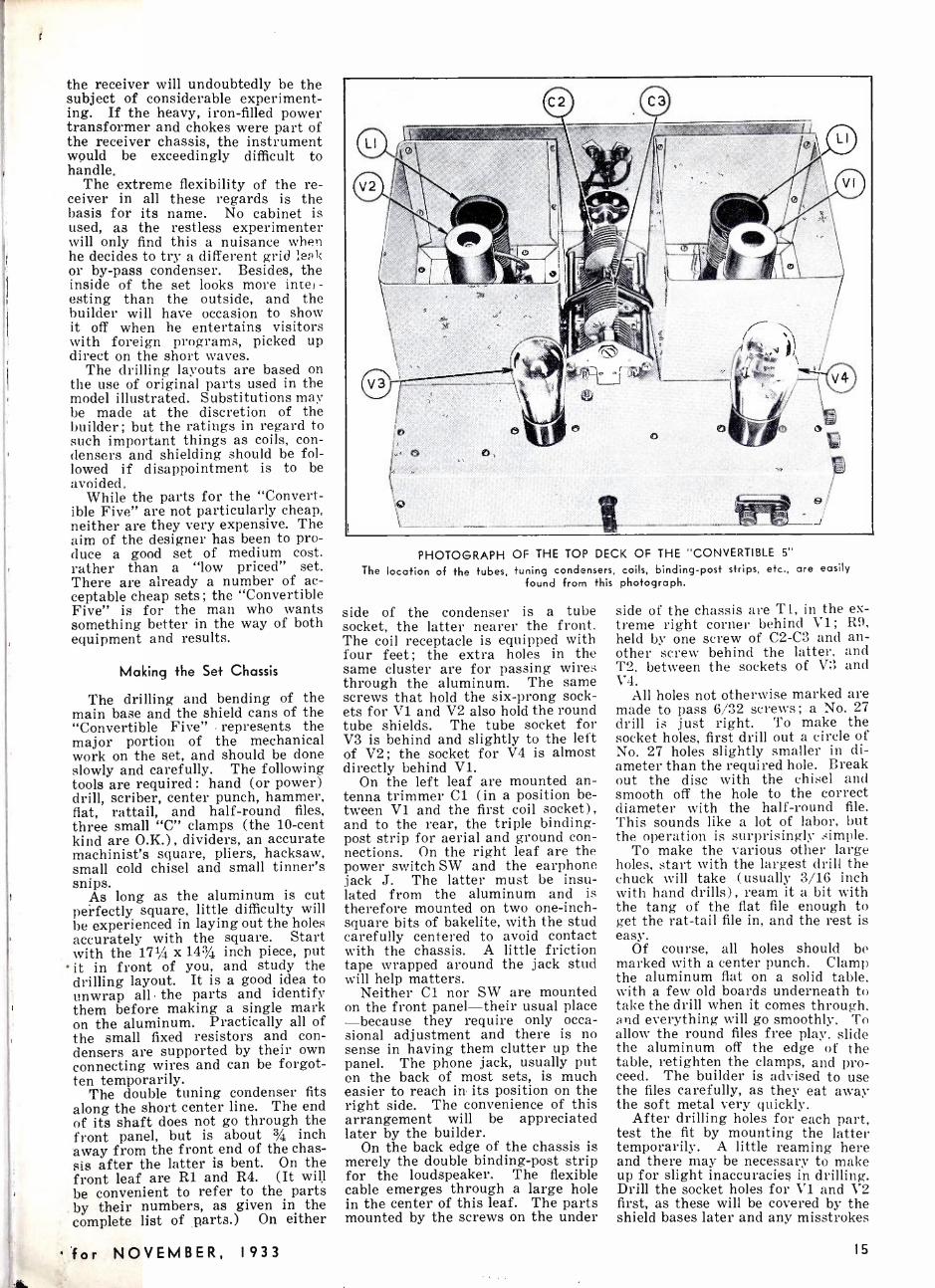
PHOTOGRAPH OF THE TOP DECK OF THE "CONVERTIBLE 5"
The location of the tubes, tuning condensers, coils, binding -post strips, etc., are easily found from this photograph.
side of the condenser is a tube socket, the latter nearer the front. The coil receptacle is equipped with four feet ; the extra holes in the same cluster are for passing wires through the aluminum. The same screws that hold the six -prong sock- ets for V1 and V2 also hold the round tube shields. The tube socket for V3 is behind and slightly to the left of V2; the socket for V4 is almost directly behind V1.
On the left leaf are mounted an- tenna trimmer Cl (in a position be- tween V1 and the first coil socket), and to the rear, the triple binding - post strip for aerial and ground con- nections. On the right leaf are the power switch SW and the earphone jack J. The latter must be insu- lated from the aluminum and is therefore mounted on two one -inch- square bits of bakelite, with the stud carefully centered to avoid contact with the chassis. A little friction tape wrapped around the jack stud will help matters.
Neither Cl nor SW are mounted on the front panel -their usual place -because they require only occa- sional adjustment and there is no sense in having them clutter up the panel. The phone jack, usually put on the back of most sets, is much easier to reach in its position on the right side. The convenience of this arrangement will be appreciated later by the builder.
On the back edge of the chassis is merely the double binding -post strip for the loudspeaker. The flexible cable emerges through a large hole in the center of this leaf. The parts mounted by the screws on the under
side of the chassis are Ti, in the ex- treme right corner behind V1; R9, held by one screw of C2 -C3 and an- other screw behind the latter, and T2, between the sockets of V3 and V4.
All holes not otherwise marked are made to pass 6/32 screws; a No. 27 drill is just right. To make the socket holes, first drill out a circle of No. 27 holes slightly smaller in di- ameter than the required hole. Break out the disc with the chisel and smooth off the hole to the correct diameter with the half -round file. This sounds like a lot of labor, but the operation is surprisingly simple.
To make the various other large holes, start with the largest drill the chuck will take (usually 3/16 inch with hand drills), ream it a bit with the tang of the flat file enough to get the rat -tail file in, and the rest is easy.
Of course, all holes should be marked with a center punch. Clamp the aluminum flat on a solid table, with a few old boards underneath to take the drill when it comes through. and everything will go smoothly. To allow the round files free play, slide the aluminum off the edge of the table, retighten the clamps, and pro- ceed. The builder is advised to use the files carefully, as they eat away the soft metal very quickly.
After drilling holes for each part, test the fit by mounting the latter temporarily. A little reaming here and there may be necessary to make up for slight inaccuracies in drilling. Drill the socket holes for V1 and V2 first, as these will be covered by the shield bases later and any misstrokes
I5

RECEIVER
LI ---Sì lp
CI
TICKLER
LI ;
VI
RZ
ANT. GND.
POWER PACK
T3 5v
ov. 60- A.C.
PRI
HO V. OUTLET
R.F.2
V2 = V3 io - CIO
SI R3
2- ' g C9 . TI 6
R5 I % R
II l 1 C3
Cil
L1 ` ,- - _ < _ C13 r 1
e5 C6 - - _ I CI4= I R,F.1 R4 ,
L ..... 411110* 411Mra"114111111111a11r 7r , FIELD ,11 fR / Sw. R9
L 1 ó
Cl7 S
2 4 i
J
3PKR.
V5 1 GI5 C16
HI-VOLTAGE
2.5v.
T 6 WIRE CABLE
( I 5 '..`..i : 6 PRONG SOCKET
2 40
6 PRONG PLUG
SCHMATIC CIRCUIT OF THE "CONVERTIBLE 5" AND ITS POWER UNIT Choke T5 is not required if the field of the speaker is used as a choke.
RESISTORS RI-2,000-ohm potentiometer ( Electrad
Super Tonatrol No. 553). R2 -300 ohms, 5 watt (Trutest -Wholesale
Radio Service Co.). R3 -5 megohms, I watt (Lynch). R4- 50,000 -ohm potentiometer ( Electrad
Super Tonatrol No. 557). R5- 250,000 ohms, I watt ( Trutest). R6 -2,000 ohms, 5 watt (Trutest). R7-400 ohms, 5 watts (Electrad). R8- 250,000 ohms, I watt ( Trutest). R9- I5,000 ohms, 50 watts, wire wound,
with 3 movable taps (Electrad). CONDENSERS
CI -20 mmf. midget (Hammarlund). C2, C3- Double section variable, 100
mmf. per section (National type SE -100). C4, C5, C6 -.0I mf. mica (Solar). C7 -0.5 mf. 500 volts electrolytic (Tru-
test). C8 -.000l mf. mica (Solar). C9- .00025 mf. mica (Solar). C10 -.01 mf. mica (Solar). CII -2 mf., 500 volts electrolytic (Tru-
test). C12 -5 mf., 35 volts electrolytic ( Trutest). C13 -25 mf., 50 volts electrolytic (True -
test). CI4 -2 mf., 500 volts electrolytic (Trutest). C15, CI6, CI7 -8 mf., 550 volts electro-
lytic. RFI, RF2 -2.5 millihenry R. F. chokes
( National). TI -300 henry impedance (Trufest). T2 -Audio transformer, not more than
3:1 ratio (Trutest). T3 -Power transformer, with low and high
voltage windings for 80 rectifier, and 2.5 vol+ filament winding (Trutest).
T4 -30 henry, 100 ohm filter choke (Tru-
of the file won't show. With these holes as experience, the holes for V2 and V3, which are more exposed in the back, will come out better.
Don't make any holes yet for the two shield cans that enclose Vi and coil L1 on the left, and V2 and the other coil, Li, on the right. (Note: all these directions as to left and right are given with the understand- ing that the edge containing the two potentiometers, R1 and R4, is near-
16
test). T5 -Same as T4, but optional. LI, LI -Pairs of plug -in coils, six prong
forms, wave ranges as follows: 13 -25, 23 -41, 40 -70, 65 -115, I15 -200 meters. Home made as per specifications to be given, or National coils Nos. 61, 62, 63, 64 and 65. 2- Special six -prong sockets for plug -in coils (National).
Wafer sockets, one each for following tubes: 58, 58, 56, 2A5, 80 (Eby).
2 -Tube shields for 58's (Trutest). I- Illuminated vernier dial (National type B). J- Single, open circuit jack (Pilot).
Sw -Snap switch for I IO volts. 2- Double binding post strips (Eby). I- Triple binding post strip (Eby). I -Insulated universal coupling (Hammar-
lund). I -Piece 1/4 inch brass rod, 11/4 inches long. I -8 wire battery cable. I -6 prong connector plug (Alden). 1 -6 prong receptable, wafer type (Eby). Tubes: Two 58's VI, V2; one 56, V3; one
2A5, V4; one 80, V5 (Sylvania). I- Dynamic speaker, 1,000 ohm field, in- put transformer to match one 2A5 (Mag- navox or Trutest).
Aluminum for receiver chassis: one piece No. 14 gauge, 8 by 12 inches, for front panel; one piece No. 14 gauge, 171/4 by 143/4 inches, for rear base; two pieces No. 20 gauge, each 21 by 53/4 inches, for shield cans. For power pack, one piece No. 14 gauge, 131/2 by 131/2 inches.
1 -50 ft. roll No. 18 solid tinned hook up wire, push -back insulation type.
I -Power cord, twisted flexible pair, as long as desired, with plug at end.
1- Female receptacle.
est the constructor.) The bending operation requires
the C clamps and a couple of length of 11/2 x i1/2 or 2 x 4 wood blocks. Saw out the corners of the sheet as marked and score the aluminum heavily along the dotted lines that run from corner to corner. Do this on both sides of the sheet. Cut one piece of wood 117/8 inches long and clamp it carefully along one edge of the aluminum (top face to the
table). Slide the sheet over the edge of the table so that the whole 2%- inch leaf overhangs. Start bending upward by leaning heavily on the aluminum with your hands, and then complete the operation with repeated blows of the hammer. The alumi- num will not come perfectly at right angles, but don't worry about it, as you can readily press it into shape later to form a satisfactorily even box.
Repeat the operation with the other long edge, then cut the wood to 93,8 inches and repeat with the short sides. If a sufficiently heavy table is not available, use the cellar stairs or any other firmly anchored flat support. The completed chassis will be astonishingly rigid.
The front panel is simple. Place it up against the front edge of the chassis and scratch through the holes for R1 and R4 from the inside of the latter. Also spot the center hole for the dial by sliding the insu- lated universal coupling over the condenser shaft, with the short piece of brass rod in the other end of the coupling. With this center hole as a starting point, drill the dial mount- ing holes with the aid of the handy full -sized template found in the box. It is advisable to handle the front panel in this manner, rather than to drill it all up beforehand, as the bending of the chassis will make ac- curate register very difficult other- wise.
The two shield cans are identical. Drill the holes first, cut the little notches along the edge, and bend with the aid of the wood block. Bend. up the half -inch mounting lips with a pair of flat -nose pliers before clos- ing in the overlapping edges with two small machine screws. The 20- gauge aluminum will seem like paper after the constructor has bent the chassis.
There are still no holes in the chassis for the shields. Spot these through the holes in the feet after centering the shields carefully around the coil and tube sockets. The long outside edges will come flush with the outside edges of the chassis ; the front edges about 7/8 inch from the front panel.
Lastly, cut a 1/2- inch -wide slot a 1/2 inch high in the bottom edges of both cans facing the tuning con- denser, directly opposite the termi- nals of each section of the latter. These are to pass connection wires inside the shields. After testing the fit of the shields, lay them aside, as they will not be mounted perma- nently until the receiver is com- pletely wired.
All parts are mounted with small machine screws and nuts. Mount the sockets for V1 and V2 with the large filament holes to the left of the chassis; V3 socket with the filament holes to the back, and V4 socket with the large holes to the right. Exam- ine the coil sockets and you will no- tice two pairs of three holes, one group of holes closer together than the other. Mount one socket, to the left of the condenser, for antenna
SHORT WAVE RADIO

coil L1, with the close group point- ing to the front panel; the other socket, for the detector coil, to the right of the condenser with the close group pointing to the right. These positions are important as an aid to the shortest and most direct wiring.
The grid leak and grid condenser (C8, R3) are mounted upright be- tween the detector coil socket and the detector tube V2 by a small L- shaped bracket, with a flexible lead running from the top connections to the cap of the type 58 detector.
The front panel is held in place by the fastening nuts of R1 and R4 and the lower dial screw. This is plenty of support. The short piece of 14- inch brass rod is fastened in the dial stud and connects with the variable condenser shaft by means of the flex- ible coupling. This arrangement is much simpler than attempting to make the condenser shaft slide ac- curately into the dial.
The shafts on the potentiometers. as furnished by the manufacturer, are too long. Cut them short enough to accommodate any small knobs that strike your fancy.
Finish the assembly work by mounting Cl and the triple binding - posts trip on the left side of the chassis, the double b.p. strip on the back, the switch and the phone jack on the right side, and Ti, T2 and R9 on the underside. The voltage divider resistor, R9, will fit off at an angle to clear transformer T2. Inci- dentally, obtain two extra sliding contact bands for this resistor, so that you can adjust the various plate voltages properly.
Note : The detector plate coupling impedance, T1, the grid coupling condenser, C10, and the grid leak, R5, may be obtained in the form of a single case unit, made by National.
The Power Pack
The base of the power pack used with the "Convertible Five" is a simple inverted box of aluminum, drilled and bent as shown in the ac- companying drawing. The same in- structions as to handling the flat sheet of aluminum given for the re- ceiver proper apply to the pack.
Of the two holes on the left side (see pattern), the upper is for a flush -mounting 110 -volt outlet and the lower for a six -prong socket. In mounting the latter, turn it so that the two large (filament) holes are nearest the inside edge of the chas- sis. The large rectangular hole is for the power transformer.
Drill out a series of holes inside the border of this opening, break out the center piece with a cold chisel and file the edges smooth with a flat file. Test the fit of the transformer carefully and be particularly certain that none of the terminal lugs or wires touch the metal. Mount the transformer with the 5 -volt and high -voltage secondaries facing toward the socket for the 80 rectifier tube, which is just to the right. Place this socket with the filament
for NOVEMBER, 1933
2 °., 8
12"
SWITCH
wine
REG.POT.
FRONT tn?, VOL. CON
_r_24
2-1* 1 46
COIL 4_90 C t
DET. TUBE
FOAL LIGHT WI
g 1
413- JACK
I! .
5
r0 eá ill A.F t -1
i, -i tgDZ¡- ï
"Al*
-Q)--- -ow!
COIL. -4-- I SOCKET i
q
t6D1 R.F.TUBE
i3
:
1
T i
: Iv CA_BLE
Ì
RECEIVER BASE
BACK
6"
28
F-2 ï-i- i--i
IDW 2N3 A.F.
76; 76"
=1N
1
BINDING POSTS
TRIMMER
" i5 t_
. f Noe
BINDING t POSTS +
DRILLING LAYOUT OF THE CHASSIS OF THE "CONVERTIBLE 5"
Note particularly that the front leaf is shown to the rear on this drawing.
21"
m
BEND - 1
I I
I
® %I m - ---= I"-+- H I- I"+ t h1-i
SHIELD -(MAKE 2)
COMPLETE DRILLING LAYOUT OF THE SHIELD CANS
holes facing the side of the chassis that has the single large hole for the power cord.
If these directions as to position are followed, the wiring will fall in its logical place and the leads will be short and direct.
The three holes along the right edge are for the 8 mf. electrolytic filter condensers, which mount in an upright position by their own large fastening nuts. The small holes along the bottom are screw holes for the 30 -henry filter chokes. Below them are holes for a double binding -post strip.
At this point it might be well to interrupt the assembly instructions to say a few words about the loud- speaker, as this has an important bearing on the filter system of the power pack. If you have an old but perfectly good dynamic speaker with built -in field supply (thousands of such speakers were sold during re- cent years), you can eliminate the binding -post strip and use two 30- henry chokes. Plug the speaker
power cord into the 110 -volt socket on the pack, short out any switch al- ready in the cord of the speaker, and you will then control the speaker's field supply simultaneously with the power pack itself by means of the snap switch on the right side of the Convertible Five.
If you intend to buy a new speaker, get one with a field having a resis- tance of not more than 1,000 ohms. Use only one 30 -henry filter choke and by means of the double binding - post strip connect the field so that it is in series with the choke and thus acts as a choke itself, at the same time that it is receiving its own field excitation.
In either case, the speaker must be fitted with an input transformer suitable for a single 2A5 output tube. A transformer intended for push -pull 45's will work very nicely if only the two outside terminals of the primary are used, with the cen- ter -tap idle.
It is advisable to install the 110 - volt outlet on the power pack chassis
17

VIEW OF THE TOP OF THE POWER PACK
The lettering, of course, corresponds to that given in the list of parts.
UNDERVIEW OF THE POWER PACK Note how coil of the power transformer
protrudes through the cutout.
even if the second loudspeaker ar- rangement is employed ; the device costs only about 15 cents and it will prove very useful in experimental work.
Wiring the Set
With all the drilling, bending and mounting of parts done, the wiring is next. Start on the receiver chas- sis, with the shield cans still not mounted. Identify all the socket ter- minals (the tube manufacturers are again including little socket dia- grams in the packing boxes, P"n-- ;- dence be praised!) and wire all the filaments in parallel, twisting the No. 18 wire between sockets. Also run a pair of dial -light wires from the socket of the detector tube, V2. Push the eight -wire cable through the hole in the back and select any two pairs of wires for the filament supply. Parallel two wires to form a single connector. This is done to prevent voltage drop through the cable; if only one pair of wires were used, there would be an appreciable loss, as the leads in practically all such cables are only No. 18, and this is not heavy enough. Identify the other ends of the same wire and solder them immediately to the two large prongs of the six -prong plug. The eight -wire cable thus acts really only as a six -wire cord.
Select another pair of wires and run these to the snap switch. The remaining pair is for B plus and B minus. It makes no difference as to
18
M
IN 71"
rM
IaD .1+
OUTLET
5OC KET
wiisft
ct.
Ñ
1 L
POWER
2B_
CORD
Ild N
CUT OUT
tq ef SOCoKET
TRANS. -APART
4
. -4,-
CMOKES
2- -t--12+--{-- 2"-f -- ----L-
4 lu
a
L-IN
L
M
=id
r 7 7' sD 6 1 -- :
POWER PACK BASE
FILTER CONDENSERS
J
COMPLETE DRILLING LAYOUT FOR THE POWER PACK OF THE "CONVERTIBLE 5" The holes labeled "outlet" are used for mounting a female receptacle in case the speaker is of the a.c. type. These drilling layouts are suitable only if the constructor uses the major parts specified by the author. Complete mounting data for the power pack are obtained by referring to the two photographs at the left and the
drilling layout shown above.
what color lead you select for any of these connections, as long as you keep track of them carefully and fol- low them through the six -prong plug to the correct terminals of the six - prong socket on the power pack.
The B plus lead goes to the rear end of the divider resistor R9 ; the other end of the latter (nearest the dial) is grounded directly to the alu- minum.
Face the three terminals of the volume and regeneration potentiom- eters R1 and R4 toward the side of the set bearing the trimmer con- denser Cl. Ground the terminals nearest the inside surface of the chassis and both controls will then operate correctly, i.e., volume and regeneration will increase with clock- wise rotation of the knobs.
Bypass condensers C4 and C5 may be mounted by the same screws that hold the socket for V1, C6 by one of the detector stage coil socket screws, and C9 by one of the socket screws of V2. The grid condenser and leak C8 -R3 are mounted upright on the top side of the chassis, between the detector tube socket and the detector plug -in coil socket, by means of a little L- shaped bracket. All the other fixed condensers and resistors in the set are soldered directly between points in the circuit by their own lugs or connecting wires.
It is necessary to have at least one pair of plug -in coils at this stage in order to wire the coil sockets prop- erly. The No. 63 coils, which tune from 40 to 70 meters, are recom-
mended, as these are the most useful coils anyway. Trace the leads care- fully. The heavy winding is the sec- ondary. The upper end is the grid end, the lower the ground end. In- terwound with this winding is a coil of thinner wire, which acts as a pri- mary for the coil plugged in the de- tector (right -hand) compartment; the upper end goes to the plate of the first tube, V1, the lower to the r.f. choke and B plus 180 volts. This same winding on the coil used in the antenna stage (left can) is merely shunted by the trimmer condenser Cl and acts as a small absorption loop.
Tickler Wound in Slot
In a slot at the bottom of each coil is a small winding of a few turns. This is the tickler of the de- tector coil and the primary of the antenna stage coil. Note that the two coils of any numbered pair are absolutely identical and are freely interchangeable between the antenna and detector Stage coil sockets; the two smaller windings merely serve different functions in the respective positions.
Special note: The detector will os- cillate with the tickler coil connected only in one way. If you don't h't the correct "poling" the first time, simply reverse the connections to the tickler terminals of the coil sJeicet and the set will come to life immediately.
From the standpoint of circuit stability it is important to use a
SHORT WAVE RADIO
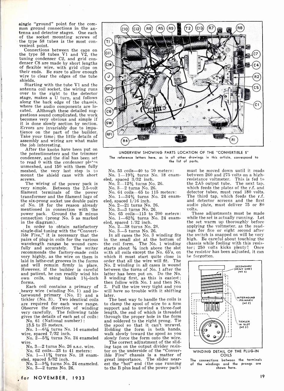
single "ground" point for the com- mon ground connections in the an- tenna and detector stages. One each of the socket mounting screws of the type 58 tubes is the most con - venient point.
Connections between the caps on the type 58 tubes V1 and V2, the tuning condenser C2, and grid con- denser C8 are made by short lengths of flexible wire, with grid clips on their ends. Be sure to allow enough wire to clear the edges of the tube shields.
Starting with the tube V1 and the antenna coil socket, the wiring runs over to the right to the detector stage, makes a U turn, and follows along the back edge of the chassis, where the audio components are lo- cated. Although these detailed sug- gestions sound complicated, the work becomes very obvious and simple if it is done slowly section by section. Errors are invariably due to impa- tience on the part of the builder. Take your time; the little details of assembly and wiring are what make the job interesting.
After the knobs have been put on the potentiometers and the trimmer condenser, and the dial has been set to read 0 with the condenser pl ' s unmeshed, and 150 with them fully meshed, the very last step is to mount the shield cans with short screws.
The wiring of the power pack is very simple. Between the 2.5 -volt filament terminals of the power transformer and the filament lugs of the six -prong socket use double pairs of No. 18 for the reason already mentioned in connection with the power pack. Ground the B minus connection (prong No. 5 as marked in the diagram) .
In order to obtain satisfactory single -dial tuning with the "Convert- ible Five," it is necessary that the pairs of plug -in coils for the various wavelength ranges be wound care- fully and accurately. The writer recommends the factory -made coils very highly, as the wire on them is laid in lathe -cut grooves in the forms and will remain firmly in place. However, if the builder is careful and patient, he can readily wind his own coils, using blank 11/2 -inch forms.
Each coil contains a primary of heavy wire (winding No. 1) and in-
.terwound primary (No. 2) and a tickler (No. 3) . Two identical coils are required for each wave range. Observe the direction of winding very carefully. The following table gives the details of each set of coils :
No. 61 (National number) :
13.5 to 25 meters. No. 1 -61/4 turns No. 14 enameled
wire, spaced 7/32 inch. No. 2-5% turns No. 24 enameled
wire. No. 3 -2 turns No. 26 s.s.c. wire. No. 62 coils -23 to 41 meters :
No. 1 -113/4 turns No. 18 enam- eled, spaced 5/32 inch.
No. 2 -93/4 turns No. 24 enameled. No. 3 -2 turns No. 26.
for NOVEMBER, 1933
UNDERVIEW SHOWING PARTS LOCATION OF THE "CONVERTIBLE 5"
The reference letters here, as in all other drawings in this article, correspond to the list of parts.
No. 53 coils -40 to 70 meters :
No. 1 -193/4 turns No. 18 enam- eled, spaced 3/32 inch.
No. 2 -12% turns No. 26. No. 3 -2 turns No. 26. No. 64 coils -65 to 115 meters :
No. 1- 343/4 turns No. 24 enam- eled, spaced 1/16 inch.
No. 2 -21 turns No. 26. No. 3 -3 turns N'o. 26. No. 65 coils -115 to 200 meters :
No. 1 -623/4 turns No. 24 enam- eled, spaced 1/32 inch.
No. 2 -38 turns No. 26. No. 3 -5 turns No. 26. In all cases the No. 3 winding fits
in the small slot at the bottom of the coil form. The No. 1 winding starts about 3/8 inch above the slot with all coils except the No. 65's, on which it must start quite close in order that all the wire will fit. The No. 2 winding in all cases is wound between the turns of No. 1 after the latter has been put on. Do the No. 3 winding first, as this is easiest ;
then follow with No. 1 and then No. 2. Pull the wire very tight and you will have no trouble with it shifting later.
The best way to handle the coils is to clamp the spool of wire to a firm support and to unwind a three -foot length, the end of which is threaded through the proper hole in the form and soldered to the right prong. Tie the spool so that it can't unravel. Holding the form in both hands, walk slowly toward the spool as you slowly force the form onto the wire.
The correct adjustment of the slid- ing taps on the output divider resis- tor on the underside of the "Conver- ible Five" chassis is a matter of great importance. The slider near- est the "hot" end (the one running to the B plus lead of the power pack)
must be moved down until it reads between 260 and 275 volts on a high - resistance voltmeter. This is fed to the 2A5 output tube. The next tap, which feeds the plates of the r.f. and detector tubes, must read 180 volts. The third tap, which feeds the r.f. and detector screens and the first audio plate, must deliver 75 or 80 volts.
These adjustments must be made while the set is actually running. Let the set warm up thoroughly before applying the voltmeter, as the read- ings for five or eight second after the switch is snapped on will be very high. Be careful about touching the chassis while fooling with this resis- tor ; 250 volts kicks plenty ! Once the resistor has been adjusted, it can be forgotten.
r-
SECONDARY (HEAVY
INTER WOUND PRIMARY
(NS 2)
TICKLER IN SLOT (NS 3)
WINDING DETAIL OF THE PLUG -IN COILS
The connections between the terminals of the windings and the prongs are
shown here.
19

By Robert S. Kruse
Illustrations by the Author
Q \MaMan* O'I
LINEARITY GRAPH
NOTES
The Maligned Modulator u 11111111111111111111111111111111111111111111111 Y 111111111111111111111111111111111111111111111111111111111111111111 I I I I I I I I I I I I I I I I l l I I I I I I I I I I I I
SUMMARY: "Your modulation sounds overmodulated, Old Man; I suggest you look over that modulator stage," quoth the Wise One. But, declareth Kruse
WITCHES cause no fear to- day, black cats are taken up by the S. P. C. A., crowds walk carelessly un-
der ladders, and business continues on Friday the 13th. Superstition is bankrupt, and black magic remains only in a few families which inherit the ability to understand New Eng- land road markings and the time- tables of the Pennsylvania Railroad.
This is an age of fact. And yet, in the 80 -meter amateur
phone band there reside today Mas- ters of Darkness, come straight from the gloom of antiquity, to whom there is neither distance, nor fact, nor any rule of physics. These wizards have but to listen to an ama- teur radio station at a distance in order to tell instantly what ails that station and to pass down Solomonic judgment -thus :
"Your modulation isn't very good, Old Man. Better fix up that modu- lator."
A Little Debunking Nonsense and rubbish ! I deny that
anyone can listen to a station in the yowling bedlam that is the principal amateur phone band and can learn anything which warrants him to publicly denounce a station. How can he discount selective fading? How can he discount stray noises? How can he discount noises in his own receiver? How can he discount the distortions in his $3.67 loud- speaker? And finally, how can he judge one station in the swarming, crowding, ephemera -dance on the amateur voice bands ? The answer is simple -he cannot.
He belongs with the other side- show freaks, the fortune tellers, the
20
The Listening Wizard at work. Note the utter confidence with which he diagnoses
your case!
peddlers of crazy patent medicines, and the purveyors of Assyrian lucky rings. In short -you needn't believe him at all.
Where Fact Resides If you wish to find out what is ac-
tually true, you must cut out such uncertainties and look at the trans- mitting equipment from nearby - measuring and testing. If the re- sults of those tests tell you nothing, they will be useful in the hands of a more experienced person who can in- terpret them. This can be done -in fact, I often do it.
No, I am not an ether -wizard ; for my guessing is done deliberately in the presence of the figures and dia- grams which the operator took di- rectly from his apparatus -and my
results will be checked back by him in the same way.
A Shortcut or Two Now after one has worked over
enough stations, a certain ability to guess ahead must, of course, de- velop; for some things keep happen- ing again and again -at one voice station after another.
So today I am able to start out by thinking, "The trouble probably isn't in the modulator," and generally that is right. Almost always the trouble is somewhere else, in any one of so many places that one could write a book about it -as indeed I have !
Lets look over a few of them. There seems to be an astonishing
percentage of stations which have a perfectly good speech system fed by a "phooey" microphone in a room full of echoes and noises. Maybe the mike was good originally and has been dropped, or fed too much bat- tery current -or is just plainly worn out. Recollect that broadcast sta- tions that still use carbon mikes get them repaired very frequently, also that they pay for a good one. The machinery of all carbon mikes is pretty much alike ; what you pay for in a mike is almost entirely the fidel- ity, which is a direct product of care in manufacture. Home -made mikes are pretty uniformly terrible - no matter what sort they are-carbon, condenser, or dynamic.
As for the room, what would you think of a broadcast station that tried to use a plain room for a studio, or that tried to sneak out of room effects by cutting down the amplifier gain and then hissing and spitting confidentially into the mike?
Well (Continued on page 43)
SHORT WAVE RADIO

Why Skip Distances? J 11111111111111111111111111111111111111111111111111111 I I I I 1111111111111111111111111111111111111111111111 I I I 11 I I I I 11111111111111111 I I I1111111111111111111111 I I I I I 111111111111 I I I I I I I I I I I 11 I I I I 111111111111111111111111111111111111111
SUMMARY a One of the biggest stumbling blocks in short waves is the phenomenon of skip distances. Signals seem to travel along nicely for a while, and then suddenly disappear, only to show up again a few thousand miles away. Why? When? How? you ask. We have consolidated most of the authentic information. and are reproducing it below. The article is fundamental, and is designed specifically for the beginner, although many an old timer will do well to refresh his memory by reading this article. Questions concerning skip distances are welcome, and will be answered to
the best of our ability.
11111111111111111111111111111111111111111I1111I1111111111111111111111111! 11111I1111111111111111111111111II II1111I11111111111111111111111I I1111!11111111111111111111111111111111I I1111111111111I I I1111111I11111111111111I I I I I I I I I I I111 r
ROBABLY the best reason that accounts for the intense in- terest in the short -waves is that great distances are span-
ned with a very small amount of ap- paratus. True, this reception re- quires a greater amount of skill than the broadcast set; and also reception is not nearly as uniform as regular broadcast reception, but it sort of "makes the cheese more binding."
The erratic . behavior of short waves first received the attention of Marconi. Following his published reports, a great number of experi- menters started investigations, un- til finally, enough data were collected to enable engineers and scientists to know the peculiarities of short waves. They found that short -wave signals were weaker closer to the transmitter than at great distances from it, in some cases ; they found a marked difference in the intensity of received signals at night as com- pared to the daytime ; they also found that the variations were sea- sonal as well as diurnal. On top of all this, the conditions vary accord- ing to the transmitted frequency.
Short -wave listeners are familiar with the peculiar reception condi- tions ; in fact, erratic reception has become so commonplace that it may hardly be considered a detrimental factor. The theory explaining the
action of short waves is extremely interesting, and should be under- stood by all short -wave listeners.
Before stating the theory of short- wave propagation, it might be well to list briefly the characteristics of the short -wave bands commonly used today :
Characteristics of Shart Waves Frequencies between 10 kc. and
about 2300 kc. (30,000 - 130 meters) : Signals lying within this band follow a very definite law and include, of course, the regular broad- cast channels, from 500 to 1500 kc. The absorption, technically called "attenuation," of these signals, is very well known, and is familiar to almost every user of a radio set.
Frequencies above 3000 kc. (be- low 100 meters) : These are espe- cially suitable for long distance communication (especially in the daytime). The strength of these sig- nals rapidly increases with fre- quency instead of decreasing, as would be expected.
Frequencies above 6000 kc. (be- low 50 meters) : At about this fre- quency a peculiar effect known as "skip- distance" manifests itself. It is found, for instance, that a signal from a given transmitter is heard at a certain point. It is also found
that the same signal from the same transmitter is also heard at another point which is much farther from the transmitter than the first recep- tion point. Furthermore, the signal cannot be heard between these two points. From an elementary stand- point, the signal sort of skips over the surface of the earth between the first point of reception and the sec- ond point of reception. This phe- nomenon is called skip- distance ef- fect. It is known that the actual skip -distance, in miles, is much greater in the winter than in the summer.
Although very great distances may be covered with very short waves, there appears to be a limiting frequency beyond which long -dis- tance communication is impossible. In other words, long- distance communi- cation becomes more feasible as the frequency increases, and then, at a certain frequency, called the limiting frequency, it falls off.
To account for these peculiar ef- fects, Kennelly in this country and Heaviside in England suggested the possibility of the existence of an ionized layer at some distance above the surface of the earth. From the properties of such a layer, they found that a signal originating from a transmitting antenna could be re- flected from the layer, just like a
FIG. I, LEFT; FIG. 2. RIGHT: ILLUSTRATIONS SHOWING THE IDEA OF REFLECTIONS AND ZONES OF RECEPTION.
for NOVEMBER, 1933 21
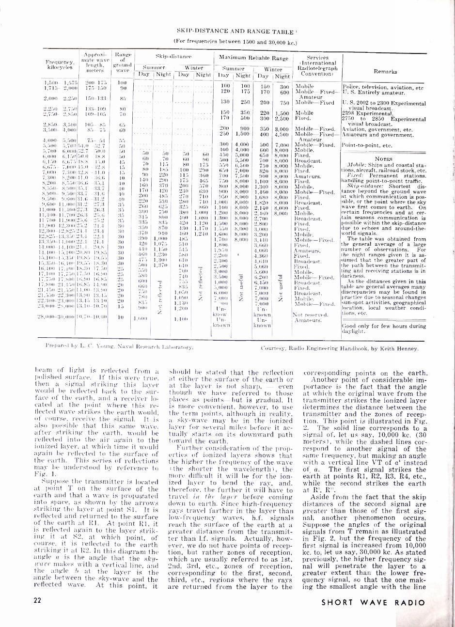
SKIP -DISTANCE AND RANGE TABLE' (For frequencies between 1500 and 30,000 kc.)
Frequency, kilocycles
Approxi- mate wave
length, meters
Range of
ground wave
1,500- 1,575 200 -175 1,715- 2,000 175 -150
2,000- 2,250 150 -133
2,250- 2,750 2,750- 2,850
2,850- 3,500 3,500- 4,000
4,000 -
.,,:,n0
."),700- 6,000- (;,150 6,675 7,000 7,:31)() 8,200 8,:,i3O 8,! m '1,:,00 !+,6nn
11,000 11,400 11 7(0) 11,900 12,:300 - I2,825 12,825-13,350 13.350-14,000 14,000-14,-100 14,41)I1-15,1111) 15,100-15,:350 15,:350-16,400 16,4(0) 17.101) 17,1110 17,751) 17,750 17,8110 17,81)11 21,450 21,450 21,550 21,550 22,:3110 22,300 23.000 23,1)00-28,01)I)
5, 500 5,700 6,0(1O 6.150 6,677)
133-109 109-105
1(15- 85 85- 75
75- 54 54.0 -52.7 )2.7 - 50.0 10.0 - 18.8 18.8 15.0
7,000 12.8 7,30(1 42.8 -41.0 8,201) 11.0 :36.(3 8,5:,(1:3(;.1; :35.1 8,11111 :i;,.1 - :33.7 11,:,)n0:3:3.7 -31.6 '1.600:31.6 -:31.2
11.000 :31.2 -27.3 I.10(127.3 26.:3
11,700 '2 t;.:3 25.6 11,91)1) 25.6 25.2 12.:300 25.2 - 21.4
2-1.4 2:3.4 2'3.4 22.4 22.1 21.4 21.4 20.8 20.80- 19.85 19.85- 19.55 19.5:5-18.30 18.30-17.50 17.50- 16.!01 16.90-16.8:, 16.85-14.00' 14.00-13.'ni. 13.90- 1:3.45 13.45 13.10 1:3.10-10.70
28,000-30,000 10.70- 10.00
100 90
85
80 70
65 60
55 50 50 50 45 45 45 40 40 41) 4(1 4 O
35 35 :35 35 30 30 30 30 30 30 30 30 25 25 25 20 20 20 20 15
10
Skip- distance
Summer Winter Day Night Day Night
50 (30 70 80 90
140 160 170 200 220 260 300 :310 335 350 370 390 420 440 460 475 500 550 580 600 660 750 780 833 900
1,000
50 70
115 185 220 290 370 420 485 530 625 750 800 835 870 940
1,000 1,073 1.15(1 1.2 :30 1,300 1,370
50 60 80
100 115 175 200 230 270 280 325 380 400 420 430 460 485 510 545 580 610 640 700 740 755 835
1,050 1,090 1,130 1,200
1,400
60 90
175 290 360 465 570 630 710 740 860
1,000 1,080 1,120 1,170 1,'210
Maximum Reliable Range Services (International
Radiotelegraph Convention) Remarks Summer Winter
Day 'Night Day I Night
100 120
100 175
150 170
300 600
Mobile Mobile- Fixed-
Police, television, aviation, etc U. S. Entirely amateur.
Amateur 130 250 200 750 Mobile -Fixed U. S. 2002 to 2300 Experimental
visual broadcast. 150 350 220 1,500 Mobile 2398 Experimental. 170 500 300 2,500 Fixed. 2750 to 2850 Experimental
visual broadcast. 200 900 350 3,000 Mobile- Fixed. Aviation, government, etc. 250 1,500 400 4,500 Mobile- Fixed- Amateurs and government.
Amateur 300 4,000 500 7,000 Mobile -Fixed. Point -to- point, etc. 400 4,000 600 8,000 Mobile. 450 5,000 650 8,000 Fixed. 500 5,500 700 8,000 Broadcast. NOTES 550 6,500 750 8,000 Mobile. Mobile: Ships and coastal sta- 650 7,000 820 8,000 Fixed. tions, aircraft, railroad stock, etc. 700 7,500 900 8,000 Amateurs. Fixed: Permanent stations. 750 8,000 1,100 8,000 Fixed. handling point -to -point traffic. 800 8,000 1,300 8,000 Mobile. Skip aistance: Shortest dis- 900 8,000 1,460 8,000 Mobile- Fixed. tance beyond the ground wave 950 8,000 1,680 8,000 Fixed. at which communication is pos-
1,000 8,000 1,820 8,000 Broadcast. sible, or the point where the sky 1,100 8,000 2,140 8,000 Fixed. wave first comes to earth. On 1,200 8,000 2,460 8,000 Mobile. certain frequencies and at cer- 1,300 8,000 2,700 Broadcast. tain seasons communication is 1,500 8,000 2,800 Fixed. possible within the skip- distance 1,550 8,000 3,000 Fixed. due to echoes and around -the- 1,600 8,000 3,200 Mobile. world signals. 1,7011 8,000 3,440 Mobile- Fixed. The table was obtained from 1,800 3,660 Fixed. the general average of a large 1,'1",0 4,060 Amateurs. number of observations. For '2,210 4,360 Fixed. the night ranges given it is as- 2.300 4,640 Broadcast. sumed that. the greater part of 0,500 5,060 Fixed. the path between the transmit- :1.000 5,600 Mobile. ting and receiving stations is in :3,500 7 6,200 Mobile- Fixed. darkness. 4,000 5,000 z
'6,450 7,000
Broadcast. Fixed.
As the distances given in this table are general averages many
6,111111
7,00!) " .0n0
c z
7,000 7,000 7,000
ó z
Broadcast. Mobile. Mobile Fixed.
discrepancies may be found in practice due to seasonal changes sun -spot activities, geographical -
Un- Un- location, local weather condi- know known Not reserved. tions, etc.
Un- Amateurs. Good only for few hours during daylight.
known known
'Prepared by L. C. Young, Naval Research Laboratory.
beam of light is reflected from a polished surface. If this were true. then a signal striking this layer would be reflected back to the sur- face of the earth, and a receiver lo- cated at the point where this re- flected wave strikes the earth would, of course, receive the signal. It is also possible that this same wave, after striking the earth, would be reflected into the air again to the ionized layer, at which time it would again be reflected to the surface of the earth. This series of reflections may be understood by reference to Fig. 1.
Suppose the transmitter is located at point T on the surface of the earth and that a wave is propagated into space, as shown by the arrows striking the layer at point Si. It is reflected and returned to the surface of the earth at R1. At point R1, it is reflected again to the layer strik- ing it at S2, at which point, of course, it is reflected to the earth striking it at R2. In this diagram the angle a is the angle that the sky- wave makes with a vertical line, and the angle b at the layer is the angle between the sky -wave and the reflected wave. At this point, it
22
Courtesy. Radio Engineering Handbook, by Keith Henney.
should be stated that the reflection at either the surface of the earth or at the layer is not sharp, - even though we have referred to those places as points -but is gradual. It is more convenient, however, to use the term points, although in reality, a sky -wave may be in the ionized layer for several miles before it ac- tually starts on its downward path toward the earth.
Further consideration of the prop- erties of ionized layers shows that the higher the frequency of the wave
( the shorter the wavelength) , the more difficult it will be for the ion- ized layer to bend the ray, and. therefore, the further it will have to travel in the layer before coming down to earth. Since high- frequency rays travel farther in the layer than low- frequency waves, h.f. signals reach the surface of the earth at a greater distance from the transmit- ter than 1.f. signals. Actually, how- ever, we do not have points of recep- tion, but rather zones of reception, which are usually referred to as 1st, 2nd, 3rd, etc., zones of reception, corresponding to the first, second, third, etc., regions where the rays are returned from the layer to the
corresponding points on the earth. Another point of considerable im-
portance is the fact that the angle at which the original wave from the transmitter strikes the ionized layer determines the distance between the transmitter and the zones of recep- tion. This point is illustrated in Fig. 2. The solid line corresponds to a signal of, let us say, 10,000 kc. (30 meters), while the dashed lines cor- respond to another signal of the same frequency, but making an angle with a vertical line VT of a' instead of a. The first signal strikes the earth at points R1, R2, R3, R4, etc., while the second strikes the earth at R', R".
Aside from the fact that the skip distances of the second signal are greater than those of the first sig- nal, another phenomenon occurs. Suppose the angles of the original signals from T remain as illustrated in Fig. 2, but the frequency of the first signal is increased from 10,000 kc. to, let us say. 30,000 kc. As stated previously, the higher frequency sig- nal will penetrate the layer to a greater extent than the lower fre- quency signal, so that the one mak- ing the smallest angle with the line
SHORT WAVE RADIO

VT, that is our solid line, may not be returned to the earth at all! It is clear, therefore, that with a fixed layer, the frequency of the signal and the angle it makes with the ver- tical determines the skip distance. This is the same as saying that for any given frequency there is a limit- ing angle of uptake from the trans- mitting antenna above which radia- tion is no longer useful because it penetrates the layer and does not re- turn to earth. Now, as the frequency is increased and the rays become more penetrating and less easily de- viated, they have to strike the layer at flatter And flatter angles in order to return to earth, and therefore, as the frequency is increased, the rays which angle sharply upward are eliminated as far as useful commun- ication is concerned, leaving only the very low -angle rays of any use.
If the frequency of our signal .
were then further increased, pene- tration would become so great that nothing would come down at all, and hence we have our limiting frequency beyond which reception at great dis- tances is impossible. These low - anrled rays, when they do return to earth, return at very great distances from T, so that long- distance com- munication is very easy.
Perhaps it would be best to ex- plain a little more fully what is meart by "zones of reception." To do this, let us refer again to Fig. 2. Our transmitter is located at point T and is sending out a constant sig- nal of a fixed, high frequency. Let us also suppose that the solid line in this figure represents the most vertical ray from the transmitter which returns to earth, and the dot- ted line, the most horizontal ray of the transmitter which returns to earth. All the rays, then, included between these two extremities rep- resent the useful rays suitable for communication. Any receiver there-
fore, located between R1 and R1 will receive the signal. The distance between T and R1 represents the skip distance. In some cases, there is a region between R1 and TV in which reception is not feasible. This region is called the secondary skip - distance region. Occasional instan- ces of tertiary skip distances have also been found.
If the effective height and density of the Kennelly- Heaviside layer is altered, the whole picture changes. If the layer is higher and less dense in electrons, conditions will be essen- tially the same, except that the limit- ing frequency will be lowered some- what ; thus, even at moderate fre- quencies, secondary skip zones may open up at night and, as is well known, critical frequencies (fre- quencies beyond which rays are not returned to earth) are much lower at night than they are in the day- time. The ideal conditions, of course, exist when the first zone of reception overlaps the second zone, which in turn, overlaps the third zone in order that there may be no missing regions intervening other than the first skip distance zone.
There are marked seasonal varia- tions in those paths which pass through those regions of the earth's surface which are subiect to wide differences in climate from summer to winter. This is particularly true in paths that pass close to the polar regions. During the summer, the polar regions are exposed to long periods of sunlight, and the pre- sumption is that the production of electrons is at a high rate. Thus, higher frequency signals are re- flected more easily, and are, there- fore, more suitable for communica- tion purposes. During the polar night, however, the situation is re- versed. The electron density is smaller, making it necessary to use much lower frequencies than can be
used in the summer time. It is not possible to use the low frequencies necessary in the winter time for summer communication because of the high absorption in the summer, so that for constant reception con- ditions in the polar regions, it is necessary to change the frequency to correspond with the season.
Of course, it is only possible here to state briefly what may or may not happen in general at different fre- quencies in the short -wave band. To assist listeners in securing best re- sults from their receivers, we are reproducing here a chart which gives the skip distance day and night for winter and summer, the maximum reliable range day and night for winter and summer for different fre- quencies corresponding to wave lengths from 10 to 200 meters. Th' services for which the various fre- quencies are intended are als' stated, as well as important remar's.
There is only one point of explan- ation needed in interpreting this chart. The third column, "range of ground wave," has not as yet been explained. A transmitting antenna radiates in all directions, similar to the radiations of light from an or- dinary electric bulb. Some of these rays travel parallel to the ground for very short distant es and are called "ground waves," while the remain- ing travel into space toward the Kennelly - Heaviside layer. The ground wave is rapidly absorbed by the surface of the earth and by ob- jects on the surface of the earth, and so soon disappears. Therefore, it is not very useful on short wave- lengths. The sky waves are those we have been discussing in this ar- ticle. In concluding, it might be in- structive to mention that although the sky wave is the important one in short -wave work, the ground wave predominates in the regular broadcast band.
Stations of the U. S. S. R. ECAUSE of the peculiar recep- tion conditions on the short
waves, many foreign stations cannot be received with good volume ;
furthermore, when they are received, you sometimes lose the announce-
- ment, because invariably the station fades at the crucial moment! This is particularly true of stations in the U. S. S. R. (Russia) .
Capt. H. L. Hall has carefully col- lected the data listed to the right for the readers of SHORT WAVE RADIO.
Keep this list in front of you when listening; and while the station is announcing, glance through the list if you expect the station to be in the U. S. S. R. The association of the announcer's voice and the written name may clinch the call or city in which the station is located, and may make the difference between identi- fying the station or not.
If any readers have compiled a similar list, send it in.
Radio Centre, Solyana 12, Moscow: U. S. S. R. List of Main Radio Stations
Wavelength KW. Freq. Leningrad RV70 349 100 857 Kharkov RV20 369 10 815 Odessa RV13 450 10 667 Moscow - Experimental 720 20 417 Sverdlovsk RV5 825 50 364 Leningrad 857 100 350 Moscow -Stalin 1000 100 300 Kiev RV9 1035 36 290 Tiflis 1071 10 280 Minsk RV10 1105 35 271 Moscow -Popov 1117 40 269 Moscow -Trade Union 1304 100 230 Novosibirsk 1380 100 217 Moscow- Comintern 1481 500 202 Moscow, Central House of the Army 45.38 10 6610 Moscow, Trade Union Station 50 20 6000 Moscow, Politechnical Museum. 77.52 0.15 Khabarovsk 70.2 20 Petropavlosk Kamschatka 60 0.5
111 1 1 1 1 11111111111111111I111111111111I111111111111111111111111111111111111111111111111I1111111111111111111I111111111111111111 I I I I I I I I I I11 I I I I I I I I I I I I I I I I I I111I I I I I1111 I I I I I I I I I I I I I I I I I I I I I I I I I I I I11111111111111I I I I I I I I I I F
for NOVEMBER, 1933 23
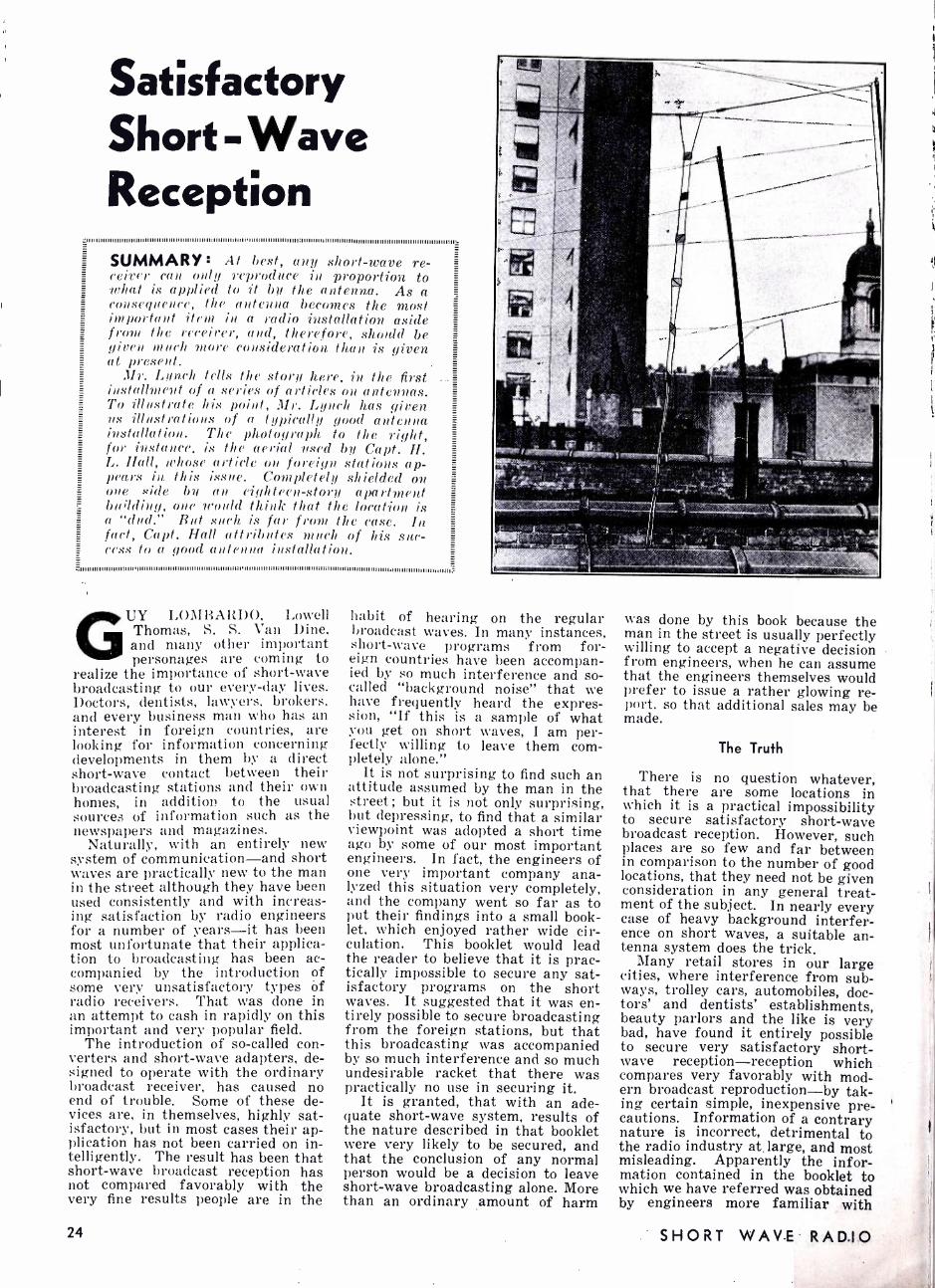
Satisfactory Short - Wave Reception SUMMARY : At best, any short -wave re-
con only reproduce in proportion to 1r/1,1í is applied to it by the antenna. As a consegn( nee, the antenna becomes the .most important item in a radio installation aside from the receiver, and, therefore, should be gi ren much more consideration than is given at i».csent.
:Ur. Lunch tells the story here, in the first installment of a series of articles on antennas. To illustrate his point, Mr. Lynch has given us illustrations of a typically good antenna installation. The photograph. to the right, for instance. is the aerial used bzt Capt. H. L. Hall, whose article on foreign stations ap- pears in this issue. Completely shielded on ove side bu an eighteen- stoat apartment building, one would think that the location is a "dud." But such is far from the case. In fact, Capt. Hall attributes much of his suc- cess to a good antenna installation.
.111111111, 1111111111111, 11111111111111111, 111111111111111111111, 111111111111, 11111111111111111111111111111111111111111111111111111 ,1111111111111111111111111:
GUY LOMBARDO, Lowell Thomas, S. S. `'an Dine, and many other important personages are coming to
realize the importance of short -wave broadcasting to our every -day lives. Doctors, dentists, lawyers, brokers, and every business man who has an interest in foreign countries, are looking for information concerning developments in them by a direct short -wave contact between their broadcasting stations and their own homes, in addition to the usual sources of information such as the newspapers and magazines.
Naturally, with an entirely new system of communication -and short waves are practically new to the man in the street although they have been used consistently and with increas- ing satisfaction by radio engineers for a number of years -it has been most unfortunate that their applica- tion to broadcasting has been ac- companied by the introduction of some very unsatisfactory types Of radio receivers. That was done in an attempt to cash in rapidly on this important and very popular field.
The introduction of so- called con- verters and short -wave adapters, de- signed to operate with the ordinary broadcast receiver, has caused no end of trouble. Some of these de- vices are, in themselves, highly sat- isfactory, but in most cases their ap- plication has not been carried on in- telligently. The result has been that short -wave broadcast reception has not compared favorably with the very fine results people are in the
24
habit of hearing on the regular broadcast waves. In many instances, short -wave programs from for- eign countries have been accompan- ied by so much interference and so- called "background noise" that we have frequently heard the expres- sion, "If this is a sample of what you get on short waves, I am per- fectly willing to leave them com- pletely alone."
It is not surprising to find such an attitude assumed by the man in the street; but it is not only surprising, but depressing, to find that a similar viewpoint was adopted a short time ago by some of our most important engineers. In fact, the engineers of one very important company ana- lyzed this situation very completely, and the company went so far as to put their findings into a small book- let, which enjoyed rather wide cir- culation. This booklet would lead the reader to believe that it is prac- tically impossible to secure any sat- isfactory programs on the short waves. It suggested that it was en- tirely possible to secure broadcasting from the foreign stations, but that this broadcasting was accompanied by so much interference and so much undesirable racket that there was practically no use in securing it.
It is granted, that with an ade- quate short -wave system, results of the nature described in that booklet were very likely to be secured, and that the conclusion of any normal person would be a decision to leave short -wave broadcasting alone. More than an ordinary amount of harm
was done by this book because the man in the street is usually perfectly willing to accept a negative decision from engineers, when he can assume that the engineers themselves would prefer to issue a rather glowing re- port, so that additional sales may be made.
The Truth
There is no question whatever, that there are some locations in which it is a practical impossibility to secure satisfactory short -wave broadcast reception. However, such places are so few and far between in comparison to the number of good locations, that they need not be given consideration in any general treat- ment of the subject. In nearly every case of heavy background interfer- ence on short waves, a suitable an- tenna system does the trick.
Many retail stores in our large cities, where interference from sub- ways, trolley cars, automobiles, doc- tors' and dentists' establishments, beauty parlors and the like is very bad, have found it entirely possible to secure very satisfactory short- wave reception -reception which compares very favorably with mod- ern broadcast reproduction -by tak- ing certain simple, inexpensive pre- cautions. Information of a contrary nature is incorrect, detrimental to the radio industry at, large, and most misleading. Apparently the infor- mation contained in the booklet to which we have referred was obtained by engineers more familiar with
SHORT WAVE RADIO

mathematics and slide rules than With modern short -wave receiving systems. My own first reactions to short -wave broadcasting were nega- tive. I was not inclined to listen to radio hash for hours on a stretch with the slight possibility of hearing a satisfactory reproduction of an English jazz band. So I determined to do something about it.
As a result of my writings on this subject, appearing in various radio publications, I receive many letters from owners of radio receiving equipment in all parts of the world. Some of these letters indicate that very satisfactory results are being secured in all parts of the world on short waves, with equipment which requires little or no engineering knowledge, and by people who know nothing more about short -wave re- ception than the average person knows about his broadcast receiver and the manner in which it func- tions.
Up to about three years ago, Cap- tain Horace L. 'Hall, who retired from a life-time at sea to engage in the pursuit of making miniature rep- licas ò -f: all types of marine craft, found that he could work better at night than during the daytime. This led him to the belief that he might be interested in listening to short- wave programs while he was work- ing, because most of the regular broadcasting in this country was already off the air by that time.
The portion of New York City in which he lives is just about the cen- ter of Manhattan Island ; and if there is any place in the world where interference could be bad, that should be it. Within the past three years, Captain Hall has received veri- fications from nearly every short- wave broadcasting station in the world. The receiver he uses is one of the older type National receivers, called an SW -5. It was designed two or three years ago, and it is still de- livering entirely satisfactory results.
The accompanying list will give you some idea of what Capt. Hall has been hearing. A short time ago, to check for myself upon the very glow- ing statements he was making con- cerning the manner in which he re- ceives programs from abroad, I visited his home. I can say that none of the statements he has made js exaggerated, and I know that his experience is now being duplicated by an increasing number of short- wave enthusiasts.
One frequently hears of a one- or two -tube receiver, operated by a farmer boy in Iowa, a priest in China, or some Amazon explorer, that. brings in stations all over the world on short waves. Some of the glowing press stories regarding these accomplishments have been greatly exaggerated. On the other hand, some perfectly remarkable re- stilts have been secured with com- paratively simple apparatus, where practically no precaution has been taken to assure the best results. These results can be duplicated, even
for NOVEMBER, 1933
By
Arthur H. Lynch
.1If 111111III II II1111111II I11I11111111111111111111111111111I1111111111111111111111II I1111I111111I11111111L
Editor's Note T is doubtful if any one in- dividual has done more to pop-
ularize short -wave broadcast re- ception than the author of the present informative article. Mr. Arthur H. Lynch is known to many readers as the former editor of RADIO BROADCAST, and Editorial Director of the Mac- kinnon -Fly Publications, which included RADIO NEWS, SCIENCE AND INVENTION, and twelve other publications.
As the editor of the former publication Mr. Lynch was first to sponsor the superheterodyne, the short -wave adapter, and au- tomobile radio for popular use. He inaugurated and conducted the famous International Radio Broadcast Tests, in 1923 -4 and 5.
While editing RADIO NEWS, he started an active campaign for auto radio and was the first to predict the present market. He called a meeting of all radio manufacturers at the Advertis- ing Club of New York and told them just what could be expected in the auto -radio field.
Mr. Lynch was among the first to realize that short -wave broad- cast reception would get nowhere if it was accompanied by the usual interference. The intro- duction of his antenna systems has made satisfactory short- wave reception possible in many poor locations.
Next month, Mr. Lynch will have an article for us on "Vari- ous Means.. of Coupling Trans- posed Transmission -Lines to All Classes of Receiver."
.1111111111111111111111111111111111i1111111111111111111111111111111111111111111111111111111111111111111r.
under the most adverse circum- stances, in nine cases out of ten, by the application of common sense.
Short -wave receivers of all types are now available which, when coupled to a suitable antenna sys- tem, will enable the user to secure satisfaction. Whether they be su- perheterodynes, regenerative receiv- ers, tuned radio -frequency receivers, or what not, really makes but little difference. With short -wave radio, as with most other types of radio, you get about what you pay for. If you want the best results, you will have the best type of receiving equipment. And it is equally true that the best need not be the most expensive. However, in order to get satisfactory results with any type of receiver, it has been found necessary to use a suitable antenna system. As a matter of fact, it has been the im- provement in the design of antennas and the realization for the need of these antennas that has made the rapid advance in short -wave broad- casting possible.
In connection with antennas, there has been so much misinformation published and the entire matter has been complicated by so much engi- neering verbiage that the person who attempts to use short waves is frightened by the mass of mathe- matics and the apparent complexi- ties the installation of such a system would involve.
Hundreds of letters have crossed my desk in the past few months in- quiring as to this and that formula for the erection of a suitable an- tenna. People ask whether the doub- let is better than the single wire, whether the cage doublet is better than the single -wire doublet, whether the transposed transmission line has any effect on the wavelengths which one desires to receive, and so on, ad infinitum.
There is really nothing complex about the erection of a suitable an- tenna. For most practical purposes, the accompanying diagram will give all the information necessary for any group of various circumstances.
For reception in the United States, of most of the European and Aus- tralian stations, an antenna suitable for reception on 50 meters will give the best results. Such an antenna will also be a satisfactory resonator at 25 meters. Since most of the im- portant foreign broadcasters oper- ate on approximately 25 and 50 meters, the single wire doublet an- tenna shown in the accompanying diagram will work out in a perfectly satisfactory manner. This antenna is extremely simple to erect and its application will give perfectly satis- factory results in nine cases out of ten.
Preferably, this antenna should run in a North -East, South -West di- rection, resulting in the best recep- tion from stations in a North -East and South -West direction. Little or no attention need be paid to mathe- matical formulas, most of which has been developed by transmitting en-
25

gineers for application to transmit- ters and receivers functioning on a single definite wavelength for com- munication purposes. Most informa- tion of that nature is of little or no use to the broadcast enthusiast who desires to receive on a number of different wavelengths.
For most satisfactory results, re- gardless of the wavelengths on which you desire to receive, an open trans- posed transmission -line, made ac- cording to the directions given in the accompanying sketch, will give you greatest freedom from local in- terference and provide greatest re- sponse from foreign broadcast sta- tions. The length of the transmis- sion line will make no practical dif- ference in your reception. It may run from a few feet to a few hun- dred feet in length. One of the sta- tions operated by the American Radio News Corporation in Cuba uses a transposed transmission -line more than 1,500 feet long. Up in Alaska, we know of another such line more than a mile and a quarter long. There is plenty of signal and great freedom from noise at the business end of a suitable antenna system, re- gardless of the length of the trans- posed transmission -line.
Some confusion still exists regard- ing the amount of interference a transposed transmission line will eliminate from short -wave recep- tion. Correspondents frequently tell me that they are troubled by auto ignition noises, especially on waves of about 17 meters. They ask whether my doublet antenna and transposed transmission line will cure this trouble. The answer is yes and no. Not too assuring, is it? Well, here's the reason.
Forgetting all about the lead -in (transmission -line) and considerin>; the antenna, whether of the doublet or any other type, we know that any variation in voltage at the antenna means a signal in the receiver. The incoming radio waves cause such changes, and so do the waves pro-
INSULATOR 91NGLE WIRE SINGLE WIRE
NV LONG 7S' LONG
CAGE: ANY SIZE FROM 2O'UP
LIGHTNING (ARRESTOR
CAGE: ANY SIZE FROM 101 VP
='j:_
1
(w¡1
TO RECEIVER
T RA N SPO 5E FEEDER
LEAD -IN
LIGHTNING ARRESTOR
A TRANSPOSED ANTENNA SYSTEM
duced by auto ignition systems, or any other sources of interference for that matter. If the voltage set up in the antenna by the auto is as strong as the voltage set up by the desired signal, we are bound to have interference. We can transpose our transmission line until we're black in the face and we can add all sorts of "eliminators" and "filters" and we won't get rid of thé interference.
But, fortunately, there is usually a way out. Then, too, it is fortunate for us that waves sent out by autos do not travel as far as regular radio waves. They are also rather limited in the height they reach. Ignition radiation from most cars spreads out from the sides, and is not strong in the front, rear or above the car.
The list to the right is a sample of the log of Capt. Hall, whose antenna is pic- tured in this article and diagrammed above. Capt. Hall believes that a good antenna is half the job -and we cer-
tainly agree with him.
Stations Heard by Capt. Hall GAS England
G GW GSF
GBW
GBC
GSA GSE GSC
GCB GDS G6RX
DIB Germany DIQ DJ A DAN DJD DJA DJC
VRT Bermuda
EAR58 Canary Is.
HJ3ABF Colombia HKD HKO HKM HJB HJ3ABD HJ4ABB HJSABD HJ4ABE
VE9JR Canada VE9GW 11
VE9DR VE9CI VE9GR CGA
VK2ME Australia VK3NE VLK
PKP Sumatra
HRB Honduras
LGB Norway
PRBA Ecuador HOB F3ICD FZS
CT1 AA Portugal
11
1,
11
11
1I
11
It
11
11
11
11
11
11
11
11
Indo -China
12R0 Italy 1AC CNR Morocco OXY Denmark PCV Holland PHI 11
PDV PDK XEW Mexico XDA XETE CMCI Cuba OPM Belgium
Congo OCI Peru XGM China NRH Costa -Rica LSX Argentina LSN It
PLE Java PMC '1
PMN FYA FTE FTA ZLW New
Zealand HVJ Vatican
City VQ7LO Kenya
Cólony EAQ Spain PRBA Brazil PSH RV59 Russia SR1 Poland HSP Siam SUZ SUV
Egypt
J1 AA Japan KDK Hawaii CT3AQ Madeira HBL Switzerland HBJ It
HBP VE9BJ Nova
Scotia VE9HX " VWY India RV1 5 Siberia TFU Iceland YV1 BC Venezuela YV3BC YV11 BMO YVR JB Johannes-
burg ZTJ "
1,
11
France 11
11
11
11
11
11
Notice to Contributors many contributors are aware, AS
it is one thing to send in a contribution to a magazine and quite another thing to have that con- tribution accepted. An editor's desk is littered with ideas and sug- gestions that have possibilities and should be worked up ; but if a pros- pective contributor has something to send in, his idea should be worked up completely before mailing.
A word or two about manuscripts: (1) use one side of the paper only ;
(2) write or, preferably, type all material and double- or triple -space everything; (3) all illustrations should be on separate sheets, each drawing on its own sheet; (4) use pencil sketches only, as we redraw all diagrams, anyhow; (5) all pho- tographs should be 8x10, glossy - small snapshots are usually worth- 'less unless they are clear and you
26
send in the negatives. Be prepared to send the appa-
ratus to us for test. In certain cases, the editors must have the equipment - on hand for either test or illustrative purposes, and a pros- pective contributor must be in a position to be able to send in the equipment.
And now, most important of all, the nature of material suitable for this magazine : look over this and subsequent issues carefully. Read the style, note the punctuation and paragraphing, the method of prep- aration, and the style of the illus- trations. Then make your manu- script as close to ours as possible.
Individuality is an important factor in a story in a literary maga- zine, but in any technical discussion the facts come first and the innu- endos second. We do not expect
masterpieces of English literature, but we do expect clear -cut, concise explanations that are readily un- derstandable.
As for payment -an important question in these days -we pay promptly upon publication of the is- sue in which the article appears. The rate of payment depends en- tirely upon the nature of the article, the manner of preparation, etc. The length of the article is not the im- portant factor involved : a short kink may contain more information than twenty typewritten pages. Catch on?
Another thing -be sure that ma- terial you send in has not appeared in other magazines. We have a complete file of many, many radio magazines here, so that if we should, perchance, catch you cribbing, well
SHORT WAVE RADIO

Bringing the S. W. Receiver Up to Date
J111111111111111111111111111111111111111111111111111111111111111111111111111111111111111111111111111111111111II II II II II111I I! II Imo II II IIIII mot 1II II II I I II II II mown IIIII I I I I Imo 1111111I1II II I1111III III I111I II II I I op II II I1I I unworn IIIII II II II III II II II II II IIIIII III II II I IIII111111IIIIIIIII IIIIIII I1111111111111111111111111111111111111111
SUMMARY: Of the thousands of short -wave receivers now in use, many use 01A's, 22's, 12A's and 71A's. . The receivers using these tubes served their purpose in the past, but are
ñ1 I 111111 I I I I I I 111111111111111111111111111111111111111111111111111111111111111111111111111 I 1111111111111111111 I 111111111111 I I I I I I I 1111 I I I I I I I I I I I I I I I I I 11111111111111 I I I I 1111111 I I I I I I I I I I I I I I I I I I I 1 I I I I I I I I I I I I I I I I 111 I I I I 111 I I I I I 11111111111111111111111 i 11111111 I 1 I 1111 I l I 11 I 1 I I 1111 I 111111 I I I l I 111 I l 111 I 111 I 11111111111111 I 1 I 1 I 11111111111111 e
now obsolete. It is the purpose of this and other articles to follow to show exactly what must be done to bring these old sets up to date with the least expenditure of time and money.
WHEN a man says that he has a three -tube receiver using 01A's, 12A's, etc., the first question that en-
ters the mind of the experimenter is, "What circuit do you use ?" After fully describing the circuit in minute detail, -which discussion usually includes added refinements or so- called tricky details- sugges- tions for improvements are made, and we have the beginning of a long conference which may last all night and which usually leads nowhere.
It is our purpose here to show
what can be done with old battery sets in order to bring them up to par; in so doing, we are perfectly aware that there are oodles of varia- tions of one- and two -tube sets ; we are also aware of the fact that when we tell you how to modernize one type of old receiver, the details are not exactly the same as for the set you have. It is always so. To de- scribe how to modernize each and every variation of two- and three - tube receiver would require volumes and volumes, since there are prob- ably more variations of simple re-
2 BRASS PLATES EACH
1 "X e ADJUSTABLE
FIG.1
2 TO 3 MEG.
8I
DETECTOR
OIA
R.F. CHOKE
REGENERATION A.F.T. CONTROL
3:1 TO 51 .00014 OR .0OO25 MF.Q
ol
O b
AUDIO AMPLIFIER
1 ¡ IO OHM-. L_J' RHEOSTAT
COIL: ANY TWO - WINDING COIL
It 2 BRASS PLATES EACH III " ADJUSTABLE
+A -A -B 6 VOLTS
DETECTOR
2TO 3 MEG. 32
-I I .0001 MF.
.....
7 00016 MF.
1O -OHM RHEOSTAT
CAP ON TUBE CONTROL GRID,
SCREEN GRID
F" I G. 2
32
OIA
PHONE
+B 9OVOLTS
R.F. CHOKE
.006 OR .IMF
T 00014 OR
.00025 MF.
100,000 OHMS
(.I MEG)
+A -A +C 3VOLTS -B PLATE
FILAMENT
AUDIO AMPLIFIER
`33
.5 MEG.
+8 -C +B 67'/2 V. 13. 5 V. 135 V.
SCREEN GRID
33 CONTROL GRID
FILAMENT
PLATE
THE TWO -TUBE OIA SET -BEFORE AND AFTER
Substituting a 32 and a 33 for the 01 A's makes a big difference.
ceivers with a given number of tubes than there are hairs on a cat.
We are fortunate in one respect :
by far the majority of simple re- ceivers have many things in com- mon ; in fact, there are so many things in common that this article is possible. For instance : the ma- jority of short -wave sets use ca- pacity control of regeneration ; they almost all use a conventional antenna coil -only a small number use doublets -and last but not least, transformer coupling between de- tector and audio prevails. In the sets to be described, the original and modernized diagrams will be given.
Two Tubes Using O I A's
One of the most popular sets a few years ago was the original Junk Box receiver designed by our own Robert Hertzberg. The receiver is extremely simple : it uses two tubes, both 01A's, in a conventional, time - tested circuit. See Fig. 1. There have been no great advances in cir- cuit design since this set was de- veloped ; to obtain better reception, all that can be done is to install more modern tubes -tubes that are de- signed to deliver greater signals.
2 -volt operation: This famous cir- cuit may be easily redesigned to ac- commodate the new tubes. The first tube may be replaced by a 32, and the audio tube by a 33 ; the result is a receiver as modern as possible at this writing.
The revised diagram is shown in Fig. 2. The first thing to do is to replace the four -prong socket used with the audio OlA with a five -prong socket ; the same socket may be used with the 32 as was used with the first tube -the 01A- before. Thus, only one new socket is required. The connections to the first tube socket remain the same substantially ; the former control grid post is now the screen connection, while the grid leak and grid condenser connect to the cap on the top of the 32 tube. Next, remove the audio transformer, and in place of its primary insert a 100,000 -ohm resistor (100,000 is the same as .1 megohm, or meg.) ;
in place of its secondary, insert a .5 megohm resistor. Then connect the junction of the r.f. choke and
for NOVEMBER, 1933 27

the .1 meg. resistor to the grid of the 33 through a. fixed condenser which may have any value between .006 and .1 mf. The 10 -ohm rheo- stat is retained. Connect the screen grid of the 32 to 67.5 volts and the screen of the 33 to the B plus side of the phones. Finally, connect the various C leads, finish the few con- nections to the socket of the 33, and the job is finished. For convenience, the socket connections of the 32 and 33 are given in the insert of Fig. 2.
Note that the original circuit of Fig. 1 used no C bias on the audio stage. This point was not over- looked in the original design of the set, but since it was made from spare parts in the junk box, the question of quality was not consid- ered important. In the revised ver- sion of Fig. 2, a C battery is neces- sary for the successful operation of the output tube.
Another point of interest is the fact that the audio transformer used in Fig. 1 was replaced by a standard resistance -condenser com- bination. True, transformer coup- ling gives better results - -from the standpoint of volume -than resist - ance coupling, but not in cases where the coupling takes place from a screen -grid tube. Many sets use the second or primary of audio transformers in place of the .1 meg. resistor shown in Fig. 2; however, the resistor is to be preferred. Try both and see which works better in your own case.
The changes shown are for opera- tion from two dry cells in series; if operation front a six -volt SOU FCC is desired, then the filament resistor should be changed to 15 ohms.
Detector and Two Audio
Another combination of tubes used consists of a regenerative de- tector using an OlA and two audio stages, the first using an OlA and the second a 12A or 71A. A schem- atic circuit of such a receiver is shown in Fig 3. Because of the obsolescence of the OlA tube, the same circuit may be considerably improved by rewiring the circuit to accommodate the new tubes.
6 -rnit r1 ¡,rratinn: Figure 4 is the new circuit suitable for 6 -volt opera- tion. A 36 is used as the detector. a 37 in the first -audio stage, and an 38 in the last audio stage. The socket connections of these tubes appear in the insert in the figure. The first significant change is the use of a choke and resistor in place of the first a.f.t. in the plate circuit of the 36. This arrangement allows the d.c. plate current to pass through the choke with a minimum loss in voltage. The .25 meg. resistor across this choke is used as the coupling unit. The choke does not couple, because its impedance at 1,000 cycles is far greater than 250,000 ohms (.25 meg.), so that the resistor shorts it only as far as the signal is concerned. Thus, we gain one of the best advantages of the
28
impedance -coupled amplifier, and at the same time retain all the ad- vantages of the resistance- coupled circuit.
The tubes used in this arrange- ment operate directly from the six - volt battery, so that a resistor in series with the heaters is not re- quired. The action of this circuit is exactly the same as that before the change ; the user, therefore, will not be required to get the "feel" of the receiver all over again. The in- creased response will more than compensate for the trouble and slight expense involved in making the changes.
In rewiring the sockets, be sure that you are acquainted with the socket terminals. Many men with plenty of inspiration and self -confi- dence have been brought down a peg or two after making a wrong con- nection on a socket. Don't guess, be sure. Analyze the original and final circuits carefully before going to work ; for, as the old saying goes,
"It's better to erase a line than to change a wire." 2 -volt operation: The circuit for
2 -volt operation requires, of course, a different tube arrangement. In this case, we suggest a 32 as the de- tector, a 30 in the first a. f. stage, and 33 in the output stage. Here again we revert to the resistance - coupled idea discussed with refer- ence to Fig. 2. For the benefit of those curious experimenters who want to know the "why" of every- thing, it might be well to state why a combination choke- resistance combi- nation is used in one case, but not in another. The reason lies in the difference in plate resistance be- tween the 32 and the 36. The type 32 tube has an internal plate re- sistance of 1.15 megohms, while the 36 has an internal plate resistance of but 200,000 ohms (.2 megohm). Since the higher impedance tube cannot have a choke of reasonable size in its plate circuit, because of the shunting effect of the distributed
01A
, 1 j 2 BRASS PLATES
S * 1" EACH ADJUSTABLE
1
2 OR 3 MEG. vV,M
IL .000I MF.
oom
'1700014Hr.
FIG. 3
OMM RMEOSTAT
R.F CHOKE
.
00014 OR
.00023 Mr.
A.F.T. ANY RATIO
I
OIA
pp
A+ A- C+ B+ 6VOLTS B- 45V.
36 DETECTOR
2 OR 3 MEG. .004TO .1 M. R.F.
CHOKE
-100 .25 MEG.
1
C- B+ C/ 4.5V. 90V. 9V.
CATHODE 37 38
2_A.F.
ç
A. F.
B+ 135 V.
SCREEN GRID
PLATE
SCREEN GRID
A .F.T. CONTROL
GRID
(CAP) Z BRASS PLATES
1"x1 "LACH ADJUSTABLE
.000111E aR
.00014 rip;
.00014 OR
.000u Mr.
FIG 4
C+ e-
A+ A- . VOLTS
CATHODE
CONTROL GRID (CAP)
SCREEN GRID
9+ 67%1V.
SECONDARY OF A.F.T. (ABOUT 500 HENRIES)
C- 9V.
B+ C- 135V. 13%2V.
I 2 BRASS PLATES
1" x 1" EAC M ADJUSTABLE
b 1
32 2 OR 3 MEG. DETECTOR
.0001Mí. L
00014 rl r
FIG.5
25 OHMS
R. F.
CHOKE
CATHODE
. 006 TO
.1MF.
30
A.F.T. ANY RATIO
HEATER
PL ATE
33 22 A.F.
.1 MEG.
700014 OR
.00025 Hr.
At A- 3 VOLTS
B+ 67i2V.
C- 9 V.
C- 13%V.
PLATE
REVISING THE "STANDARD" THREE -TUBE SET This set is easily "rehashed for 6- and 2 -volt operation.
SHORT WAVE RADIO

capacity of the choke, resistances must be used ; hence, the type 32 tubes have resistors in their plate circuits. Catch on?
The socket connection for the tubes used in the circuit of Fig. 5 are shown in either Fig. 2 or Fig. 4; the socket connections for the 30 used in Fig. 5 are exactly the same as for the OlA used previously.
R. F., Detector, and Two Audio
In the four -tube field, the com- bination using a 22 as a tuned r.f. amplifier, an 01A as a detector, an OlA in the first -audio stage, and 12A or 71A in the last audio stage was extremely popular. A represen- tative circuit using this combina- tion is shown in Fig. 6. (This is the famous Pilot "Super- Wasp," probably the most popular s.w. re-
ceiver of the past ten years) . Note that the antenna coil of this circuit is connected a little differently than the antenna coil of the preceding circuits. The reason for the change is simple : most of the coils used for s.w. work a few years ago had but two windings in order to accommo- date a four -prong socket (there were no sevens in those days!). When the first tube is regenerative, one of the coils must be used as the sec- ondary -the tuned circuit -and the other must be used as the tickler. In the case of the circuit of Fig. 6, the second tube is regenerative; therefore, the coil ordinarily used as the tickler is now used as the an- tenna coil. O.K.?
6 -volt operation: For this class of service, all the sockets used in the old arrangement must be replaced by five -prong sockets. Although the
FIG.6
22
.00014 MF. /
.OIMF.
10 OHMS 15 OHMS TOTA
R.F.CHOKE .00014 OR_00025ME
01 12A
i 0
MEG. 2 OR 3
FIG.T
.00014 M F. Ì
o o
A+
10 OHM RHEO.
A- B+ 6,Yzu
36
B+ C- 45v. 4.5V.
R.F.CHOKE r 06\--1
02 OR 3 MEG. +AM,
.006 TO .1 MF.
.00014 - OR .00025
M F.
37 S MEG.
.
B+ C- 90V. 9V.
.000111E
.00014 M F.
A F. T. ANY RATIO
pb a Q O J O
38
B+ 135v.
.25 MEG.
.01 MF.
C- CHASSIS 1.5V. B - C+
FI G.8
.00014 NIF.
32 OR 34
A+ A-
SECONDARY OF A.F.T.
(ABOUT 500 HENRIES)
B+ C- 67 %aV. 9V.
R.F.CHOKE _ Iii006TO
1
o r b y
.OI MF.
50HM RY,O.
C- 3 V.
.01 1.1
.00014 MF.
.0001 MF.
2 OR 3 MEG.
.00014 OR
.00025 M F. -
.I MEG:
ii1111111111111
30
C- 13.5 V.
.1MF.
A.F.T. ANY RATIO
á o
33
B+ 135 V.
I
p
A+ A - C+ B-
B+ 67%aV.
C- 9V.
- 13.5 V
Bi- 135V.
THE OLD FOUR -TUBE SET BEFORE AND AFTER
Four of the modern tubes can do wonders for this old- timer.
for NOVEMBER, 1933
1
22 and the 36 are both screen -grid tubes, the 36 is equipped with a heater which requires an additional contact. Here again, (see Fig. 7) the first a.f. transformer is discon- nected and its secondary used as a choke in the plate circuit of the de- tector; it is shunted by the .25 meg. (250,000 ohm) resistor for the rea- son described previously. Note, also, that the fixed resistor of 15 ohms, used in the original circuit to cut the filament voltage on the 22 tube to 3.3 volts, is not required in the revised circuit, as all tubes operate directly from a six -volt storage bat- tery ; the filament rheostat is also removed.
Other than the few major changes mentioned, the fundamental connec- tions of the circuit remain the same. Although the difference in results will be marked, the changes are few and are certainly warranted. In re- wiring the filament circuit, be sure that the heaters of the tubes con- nect only to the storage battery; to place heater and cathode at the same potential, which may give quieter operation in some cases, connect a center -tapped 20 -ohm resistor across the heater terminals, and ground the center tap.
2 -volt operation: This same orig- inal circuit lends itself very nicely to two -volt operation. The r.f. stage may be either a 32 or 34; the de- tector, a 32 ; the first audio, a 30; and the output stage, a 33. The schematic circuit of the revised dia- gram is shown in Fig. 8. Since the detector is a 32, the plate load must be a resistor, and is shown as such on the diagram. Because the tubes are rated at 2 volts, and since in all probability two dry cells will be used in series to supply the filament, a rheostat must be connected in series with the filament terminals to drop the voltage. Other than the few changes outlined, the circuit remains about the same. Only one socket will have to be changed -the last audio, from a four -prong to a five prong.
Concluding Notes
Even though you may be inter- ested in only one of the circuits shown here, do not fail to study the entire article because there may be some point that was not mentioned in connection with the one you are interested in, but which was covered when describing another set. Lack of space does not permit us to re- peat every detail several times.
There is no doubt about the fact that many, many readers want in- formation on rewiring their re- ceivers for a.c operation. They will not be disappointed ; for in the fol- lowing issues of SHORT -WAVE RADIO, details of modernizing obsolete re- ceivers will be continued. In tin meantime, if there are any questions pertaining to these articles that you would like answered, write in, but be sure to enclose a stamped, self - addressed envelope for reply. There is no charge for this service.
29

Naval Time -Signa THE first authentic time -signal
schedule of the Navy Department received in a long time is tabulated at the right.
The time signals are of three or- ders of precision, each suitable for different classes of service. These different classes are indicated by one, two, and three asterisks, as ex- plained in the chart. The time sig- nals themselves are easily recog- nized, in the case of code, by short dots, a second in length.
We wish to thank Commander B. V. McCandlish, Acting Director of Naval Communications, for his excellent cooperation in preparing this tabulation for SHORT WAVE RADIO. The schedule is correct to October 1, 1933, insofar as it is pos- sible to foretell at this time.
Schedules for W3XAL and W3XL; Bound Brook, N. J.
W3XAL operates from 12:30 to 6:30 p. m. every day except Friday and Saturday on 17,780 kc. ; and on Saturday, from 3:00 p. m. to 12:00 m. on 6,100 kc. Programs are gen- erally the same as those of WJZ.
W3XL operates on 6, 425 kc. with an irregular experimental schedule consisting mostly of experimental relay work ; no regular transmission time can be given. Time is E. S. T.
What About Television? THE present status of television
was summed up in a short article which appeared in the New York Times. Mr. B. McCargar, president of Television Laboratories, Ltd., de- clared that television is ready for launching, but will require a large outlay of capital.
"As to the immediate future of television," he said, "air picture transmission will tend definitely to- ward the ultra short -wave channels with its own separate set -up."
The general inauguration of tele- vision will probably be sectional, and chain coverage will be practical only fter the establishment of relay sta-
tions at intervals of about twenty - five to fifty miles.
Mr. McCargar also said that recent experiments showed that the useful range of television in the ultra short waves is about seventy -five miles, al- though the power of the transmitter was not stated.
The process used by the Television Laboratories is largely that de- veloped by Phil T. Farnsworth who, at the age of 22, designed the first cathode -ray tubes for both reception and transmission with electrical scanning.
30
Schedule Time (Greenwich
civil) Station
0255 to 0300 (9:55 to 10:00
P.M. E.S.T.)
, Washington, D. C.
Arlington, Va. (Washington, D. C.) ... . .
Annapolis, Md. ( 'Washington, D. C.)..... Mare Island (San Francisco, Calif.)
Honolulu (Pearl Harbor), T. H...
Call Sign
NAL
NAA
NSS
NPG
NPM 0355 to 0400 (10:55 to 11 P.M. E.S.T.) 0425 to 04_i0
(11:2.5 to 11:30 A.M. E.S.T.)
0455 to 0500 (1 1 :55 to 12.00 Noon E.S.1'. 1
0755 to 0800 (2:55 to 3:00 A.M. E.S.T.)
1255 to 1s00 (7:55 to 8:00 A.M. E.S.T.)
s Darien (Balboa), (C. Z NBA
Cavite (Los Banos), IP.1 :Annapolis, Md. (Washington, D. C.)..... Arlington. Va. (Washington, D. C.) ..... Annapolis, Md. (Washington, D. C.).....
I (Arlington. Va. '(\Washington, D. C.)..... Mare Island (San Francisco), Calif
Honolulu (Pearl Harbor), T. H.
NPO
NSS
NAA
Frequency in kilocycles and type of emission, Al unless otherwise
noted
Material Broadcast
690 A3
1113 19,050
17.8 A
42.8 A; 108; 12,885
16,180
46 (56 A2 8,872 17,744
Time signals.*
Rebroadcast of }Washington, D. C. jTime signals.*
Time signals. * **
}Time signals. *$
17.8 A 4,525 113
NSS
NAA
NPG
NPM
s Cavite (Los Banos), I P. I. NPO
1655 to 1700 (11:55 to 12:00 Noon E.S.T.)
1755 to 1800 (12:55 to 1:00 P.M. E.S.T.)
2055 to 2100 (3:55 to 4:0) P M. E.S.T.)
Washington, D. C NAL
Arlington, Va. (Washington, D. C.) NAA
Annapolis, Md. (Washington, D. C.) NSS
Mare Island (San Francisco). Calif NPG
Honolulu (Pearl Harbor). T. H... NPM
17.8 A
113 A2....... 9,050
42.8 A:108: 8,590
8,090
Time signals.*
Time signals.*
Rebroadcast of }Washington, D. C. Time signals.*
f22.9 9,050
690 A3 '113 A2
8,410 12,615 16,820
17.8 A
J42.8 A; 108; 112,885
8,090
Time signals. *$
Time signals.*
J
Rebroca of }Washiadngtonst D. ,
jTime Signals.* C.
Darien (Balboa), C. Z.. NBA 46 Time signals. * **
Annapolis, McI. (Washington, D. C.).... Arlington, Va. (Washington, D. C.)....
NSS
NAA
17.8 A.
9,050 and 113.... 2355 to 2400 (6:55 to 7:00 P.M. E.S.T.)
Arlington, Va. (Washington, D. C.).... Honolulu (Pearl Harbor), T. H
NAA
NPM
9,050 and 113....
26.1 106
Time signals.*
Time signals.*
}Time signals. **
*First -order time signals. These are precision time signals for chronometer rating and scien- tific use, normally correct as broadcast to less than one -tenth of a second. * *Second -order time signals. These are time signals for chronometer rating and ordinary use. normally correct as broadcast to less than five -tenths of a second, having a generally constant lag. ** *Third -order time signals. These time signals are satisfactory for ordinary commercial and domestic timing, but not satisfactory for chronometer rating or precision timing, on account of a varying lag within comparatively wide limits. $Controlled by Manila Central Observatory. IType A, continuous wave. IType Al, unmodulated continuous wave. IType A2, continuous wave modulated at audible frequency. IType A3, continuous wave modulated by speech.
NOTE. -In the event of a failure or an error occurring in any of the time signals, except the rebroadcast of Washington time signals at San Francisco and Honolulu, another time signal will be transmitted one hour later on the same frequency. San Francisco, in the event of a failure or error occurring in the Washington time signal, will transmit a time signal from the clock at that point. For Eastern Standard Time, subtract five hours from Greenwich times listed.
SHORT WAVE RADIO

1
RADIO SYMBOLS
FILAMENT -TYPE FILAMENT -TYPE DIODE, HALF -WAVE FULL -WAVE RECTIFIER RECTIFIER
FOUR ELEMENT CATHODE -HEATER
TETRODE
FIVE ELEMENT FILAMENT -TYPE
PENTODE
DIODE RECTIFIER WITH CATHODE
THREE ELEMENT FILAMENT -TYPE
TRIODE
FIVE ELEMENT FILAMENT-TYPE HEATER -CATHODE DOUBLE TRIODE
PENTODE
DOUBLE DIODE- DOUBLE DIODE- TRIODE - PENTODE
PENTODE,FILAMENT PENTODE, CATHODE- FILAMENT TYPE TYPE HEATER TYPE
FIXED RESISTOR
lE
VARIABLE RESISTOR (EITHER ONE)
II ,.
,II
LOW FREQUENCY R.F.TRANSFORMER CHOKE
AERIAL (ANTENNA)
SINGLE CIRCUIT
JAC K
KEY
FUSE
GROUND
L-J
DOUBLE CIRCUIT
JACK
.. I..
I.. .. ,.. hl
G4z G2-
G5 ;. G3
ISGI
K 11H H TRIODE-PENTODE CATHODE HEATER
TYPE
FULL- WAVE RECTIFIER WITH CATHODE-HEATER
DOUBLE TRIODE, CATHODE-HEATER
TYPE Pa
G4 P Iz
3 G2 G I
THREE ELEMENT HEATER -CATHODE
TRIODE
DOUBLE DIODE - TRIODE, FILAMENT
TYPE
FOUR ELEMENT FILAMENT-TYPE
TETR ODE
DOUBLE DIODE- TRIODE ,CATHODE-
HEATER TYPE
HEATER -CATHODE PHOTO- ELECTRIC TYPE TRIODE -PENTODE CELL
POTENTIOMETER FIXED INDUCTANCE
OR R.F CHOKE
AUTO- LOW FREQUENCY TRANSFORMER TRANSFORMER
AMMETER VOLTMETER
PHONES
--+ r --- -- S.P.D.T. SWITCH S.PS.T. SWITCH
©STANDARD PUBLICATIONS INC. SHORT WAVE RADIO NOV. 1933
5agr <
MAGNETIC SPEAKER
T FIXED
CONDENSER
MILLI- AMMETER
FIELD VOICE COIL
y
DYNAMIC SPEAKER
D. P. S.T. SWITCH D.P.D.T. SWITCH
LAMP (ANY TYPE)
VARIABLE INDUCTANCE
(EITHER ONO
VARIABLE CONDENSER
CRYSTAL DETECTOR
1
T BATTERY
_ L To
PIEZO- CRYSTAL
SINGLE BUTTON DOUBLE BUTTON CARBON MICRO- CARBON MICRO-
PHONE PHONE
o
1 01 TAP OR ROTARY CONDENSER
SWITCH MICROPHONE
The radio symbols shown above are those used officially in this mag- azine, although at times there may be slight deviations, especially in cases where a change would clarify matters.
for NOVEMBER, 1933
The tubes are especially im- portant. The grids are labeled from 1 up, starting with the cathode, in all cases, regardless of which grid is the control grid. This scheme is shown by the labels on one of the
symbols. The control grid will be indicated in the actual schematic by a cap projecting from the tube.
The remaining symbols are stand- ard, and the reader should have little difficulty with them.
31
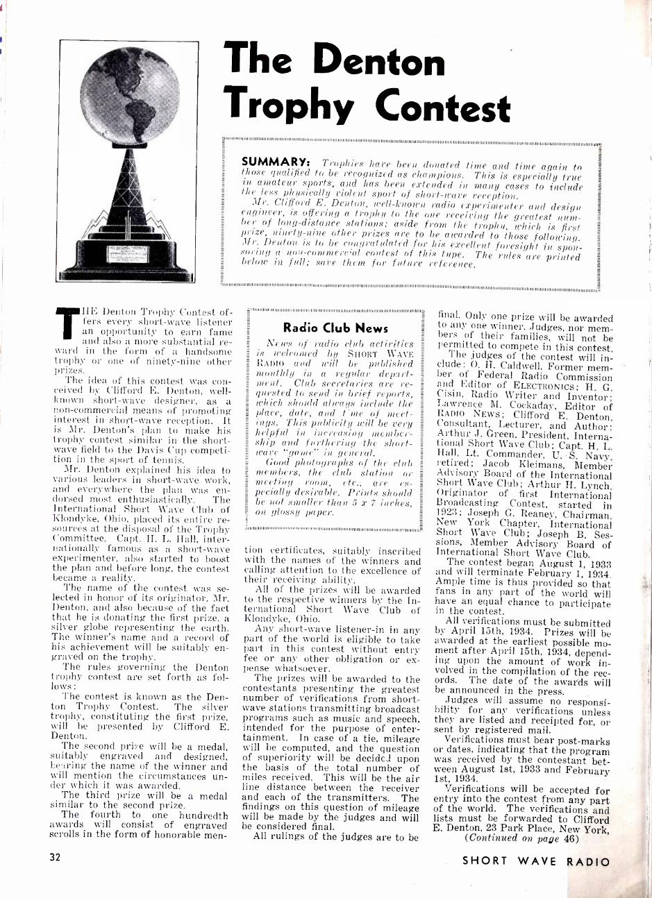
The Denton Trophy Contest
111111111111111111111111111111111111111 I 11111111111111111111111111111111111111111111111111111111111111111111111111
I I I I I I I I I I I I I I I I I I 111111111111111111111111111111111111111111111111111111111111111111111111111111111111111111111 I I
SUMMARY: Trophies have been donated time and time again to those qualified to be recognized as champions. This is especially true in amateur sports, and has been extended in many cases to include the less physically violent sport of short -wave reception. Mr. Clifford E. Denton, well-known radio experimenter and design engineer, is offering a trophy to the one receiving the greatest num- ber of long -distance stations; aside from the trophzi. which is first prize, ninety -nine other prizes are to be awarded to those following. Mr. Denton. is to be congratulated for his excellent foresight in spon- soring a non -commercial contest of this type. The rules are printed below in full; save them for future reference.
THE Denton Trophy Contest of- fers every short -wave listener an opportunity to earn fame and also a more substantial re-
ward in the form of a handsome trophy or one of ninety -nine other prizes.
The idea of this contest was con- ceived by Clifford E. Denton, well - known short -wave designer, as a non- commercial means of promoting interest in short -wave reception. It is Mr. Denton's plan to make his trophy contest similar in the short- wave field to the Davis Cup competi- tion in the sport of tennis.
Mr. Denton explained his idea to various leaders in short -wave work, and everywhere the plan was en- dorsed most enthusiastically. The International Short Wave Club of Klondyke, Ohio, placed its entire re- sources at the disposal of the Trophy Committee. Capt. H. L. Hall, inter- nationally famous as a short -wave experimenter, also started to boost the plan and before long, the contest became a reality.
The name of the contest was se- lected in honor of its originator, Mr. Denton, and also because of the fact that he is donating the first prize, a silver globe representing the earth. The winner's name and a record of his achievement will be suitably en- graved on the trophy.
The rules governing the Denton trophy contest are set forth as fol- lows:
The contest is known as the Den- ton Trophy Contest. The silver trophy, constituting the first prize, will be presented by Clifford E. Denton.
The second prize will be a medal, suitably engraved and designed, bearing the name of the winner and will mention the circumstances un- der which it was awarded.
The third prize will be a medal similar to the second prize.
The fourth to one hundredth awards will consist of engraved scrolls in the form of honorable men-
32
'U111111111IilIIIII111111111IIIIII!IIIIII Ill IIII11:111II1IIIII Ill 11II Ill IIIIIIIIIIIIIIIIIIIIIIIIIIIIIIIIL
Radio Club News N1 ws of radio club activities
is welcomed by SHORT WAVE RADIO and will be published monthly in a regular depart- ment. Club secretaries are re- quested to send in brief reports, which should always include the place, date, and time of meet- ings. This publicity will be very helpful in increasing member- ship and furthering the short- wave "gaine" in general.
Good photographs of the club members, the club station or meeting room, etc., are es- pecially desirable. Prints should be not smaller than 5 x 7 inches, on glossy paper.
11111111111111I111111111111I111111111111III1111111111111111111111111111111111111111111111111111111111111.
tion certificates, suitably inscribed with the names of the winners and calling attention to the excellence of their receiving ability.
All of the prizes will be awarded to the respective winners by the In- ternational Short Wave Club of Klondyke, Ohio.
Any short -wave listener -in in any part of the world is eligible to take part in this contest without entry fee or any other obligation or ex- pense whatsoever.
The prizes will be awarded to the contestants presenting the greatest number of verifications from short- wave stations transmitting broadcast programs such as music and speech, intended for the purpose of enter- tainment. In case of a tie, mileage will be computed, and the question of superiority will be decide) upon the basis of the total number of miles received. This will be the air line distance between the receiver and each of the transmitters. The findings on this question of mileage will be made by the judges and will be considered final.
All rulings of the judges are to be
final. Only one prize will be awarded to any one winner. Judges, nor mem- bers of their families, will not be permitted to compete in this contest. The judges of the contest will in- clude: O. H. Caldwell, Former mem- ber of Federal Radio Commission
and Editor of ELECTRONICS; H. G. Cisin, Radio Writer and Inventor; Lawrence M. Cockaday, Editor of RADIO NEWS; Clifford E. Denton, Consultant,. Lecturer, and Author; Arthur J. Green, President, Interna- tional Short Wave Club; Capt. H. L. Hall, Lt. Commander, U. S. Navy, retired; Jacob Kleimans, Member Advisory Board of the International Short Wave Club; Arthur H. Lynch, Originator of first International Broadcasting Contest, started in 1923; Joseph G. Reaney, Chairman. New York Chapter, International Short Wave Club; Joseph B. Ses- sions, Member Advisory Board of International Short Wave Club.
The contest began August 1, 1933 and will terminate February 1, 1934. Ample time is thus provided so that fans in any part of the world will have an equal chance to participate in the contest.
All verifications must be submitted by April 15th, 1934. Prizes will be awarded at the earliest possible mo- ment after April 15th, 1934, depend- ing upon the amount of work in- volved in the compilation of the rec- ords. The date of the awards will be announced in the press.
Judges will assume no responsi- bility for any verifications unless they are listed and receipted for, or sent by registered mail.
Verifications must bear post -marks or dates, indicating that the program was received by the contestant bet- ween August 1st, 1933 and February 1st, 1934.
Verifications will be accepted for entry into the contest from any part of the world. The verifications and lists must be forwarded to Clifford E. Denton, 23 Park Place, New York,
(Continued on page 46)
SHORT WAVE RADIO
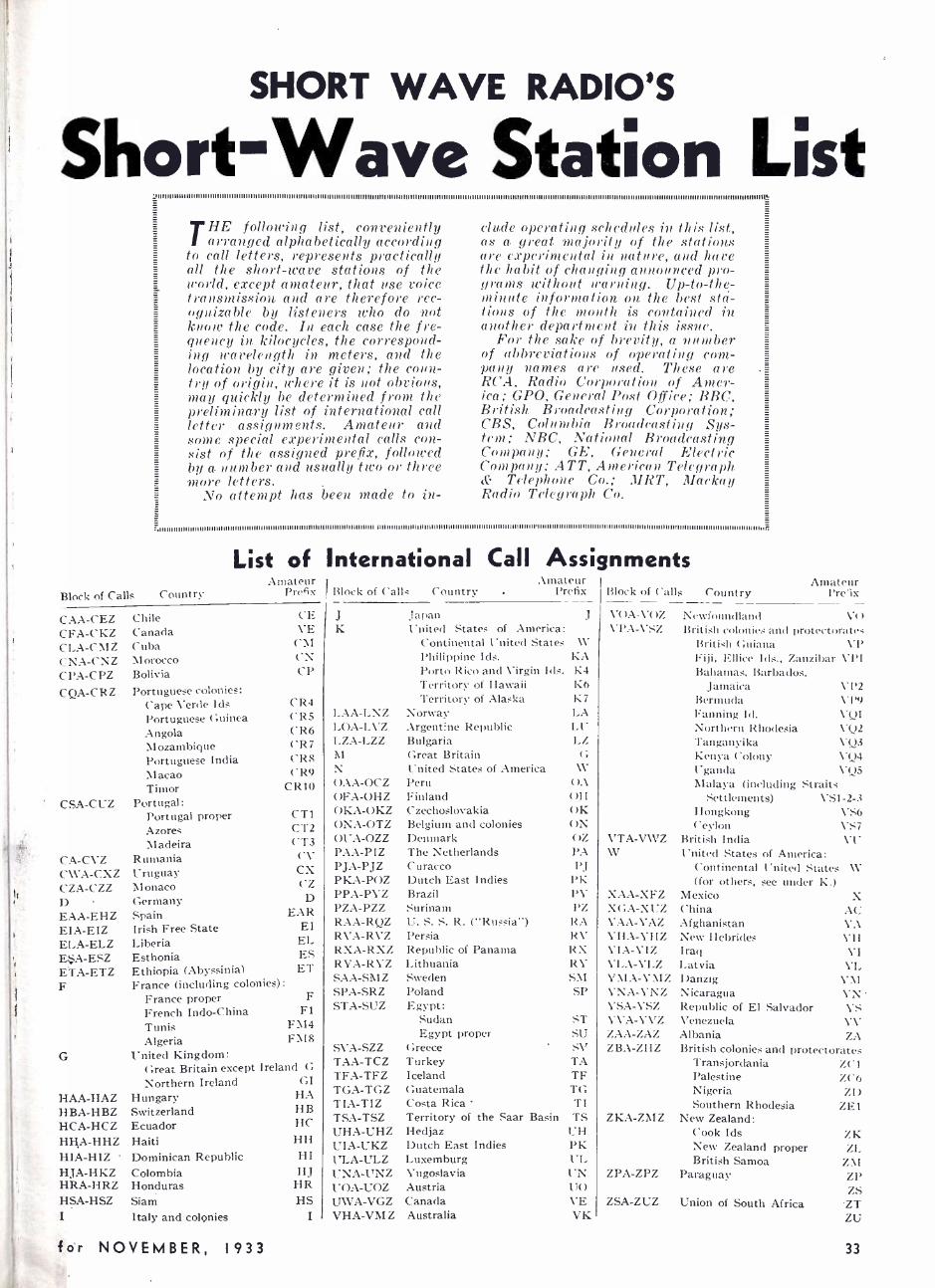
SHORT WAVE RADIO'S
Short -Wave Station List I
I I I II II II I II II II I II I I II IIIIII II II II III II II II IIIII II II II I II IIIIIIIIIIIIIIIIIL`
THE following list, conveniently arranged alphabetically according
to call letters, represents practically all the short -wave stations of the world, except amateur, that use voice transmission and are therefore rec- ognizable by listeners who do not know the code. In each case the fre- quency in kilocycles, the correspond- ing Ieavelength in meters, and the location by city are given; the coun- try of origin, where it is not obvious, may quickly be determined from the preliminary list of international call letter assignments. Amateur and some special experimental calls con- sist of the assigned prefix, followed by a. number and usually two or three more letters.
No attempt has been made to in-
elude operating schedules in this list, as a great majority of the stations are experimental in nature, and have the habit of changing announced pro- grams without warning. Up- to -the- minute information on the best sta- tions of the month is contained in another department in this issue.
For the sake of brevity, a number of abbreviations of operating com- pany names are used. These are RCA, Radio Corporation of Amer- ica; GPO, General Post Office; BBC, British Broadcasting Corporation; CBS, Columbia Broadcasting Sys- tem; NBC, National Broadcasting Company; GE, General Electric Company; ATT, American Telegraph & Telephone Co.; MRT, Mackay Radio Telegraph Co.
;.nuuuuumuwuwwuuwumuumwuuwiwunwuuuumuuunnu.uuuuuuuuunu1uuuuuuuumm,1nuwwmuunu nnuunuunnnuumiuninnnmm11uunummummuuuuunuuumumur.
Block of Calls Country
List of Amateur
Prefix
CAA -CEZ CFA -CKZ CLA -C M Z
CNA -CNZ CPA -CPZ CQA -CRZ
Chile Canada Cuba Morocco Bolivia Portuguese colonies:
Cape Verde Ids Portuguese Guinea Angola Mozambique Portuguese India ;Macao Timor
CSA -CUZ Portugal: Portugal Azores Madeira
CA -CVZ Rumania CWA -CXZ Uruguay CZA -CZZ Monaco D Germany EAA -EHZ Spain EIA -EIZ Irish Free ELA -ELZ Liberia Fi$A -ESZ Esthonia ETA -ETZ Ethiopia (Abyssinia) F
International Call Assignments Amateur
Block of Call< Country Prefix Block of Galls
CE J VE K
CM CN CP
CR4 CR5 CR6 CR7 CRS ('R9
CR10
proper CT1 CT2 CT3 CV CX CZ
D EAR
State EI EL ES ET
France (including colonies) :
F F1
FM4 FMI8
France proper French Indo -China Tunis Algeria
G United Kingdom: Great Britain except Ireland G
Northern Ireland GI HAA -HAZ Hungary HA H BA -IH BZ Switzerland H B
HCA -HCZ Ecuador HC
HH.A -HHZ Haiti HH HIA -HIZ Dominican Republic HI HJA -HKZ Colombia HJ HRA -HRZ Honduras HR HSA -HSZ Siam HS I Italy and colonies I
LAA -LNZ LOA -LVZ LZA -LZZ M N OAA -OCZ OF A -OH Z
OKA -OKZ ONA-OTZ OUA -OZZ PAA -PIZ PJA -PJZ PKA -POZ PPA -PYZ PZA -PZZ RAA -RQZ RVA -RVZ RXA -RXZ RYA -RYZ SAA -SM Z
SPA -SRZ STA -SUZ
SVA -SZZ TAA -TCZ TFA -TFZ TGA -TGZ TIA -TIZ TSA -TSZ UHA -UHZ UTA -UKZ ULA -ULZ UNA -UNZ UOA -UOZ LTWA -VGZ VHA -VMZ
Japan United States of America:
Continental United States Philippine Ids. Porto Rico and Virgin Ids. Territory of Hawaii Territory of Alaska
Norway Argentine Republic Bulgaria Great Britain United States of America Peru Finland Czechoslovakia Belgium and colonies Denmark The Netherlands C uracco Dutch East Indies Brazil Surinam U S S R. ( "Russia ") Persia Republic of Panama Lithuania Sweden Poland Egypt:
Sudan Egypt proper
Greece Turkey Iceland Guatemala Costa Rica Territory of the Saar Basin Hedjaz Dutch East Indies Luxemburg Yugoslavia Austria Canada Australia
J VOA-VOZ \"l'.-\-\'SZ
\V KA K4 K6 K7 LA LI I-Z
G \\'
OA OH OK ON OZ PA PJ
PK PV PZ RA RV RX RV SNI SP
ST SU SV TA TF TG TI TS UH PK UI. 1"N U( ) VE VK
VTA-VWZ W
XAA-XFZ XGA-XUZ YAA-YAZ VHA-YHZ VIA-VIZ YLA-YLZ YMA-YMZ YNA-VNZ YSA-YSZ YV A-YVZ ZAA-ZAZ ZBA-ZHZ
ZKA-ZMZ
ZPA-ZP7.
ZSA-ZUZ
Country
Newfoundland
Amateur Pre 'ìx
V( ]
British colonies and protectorates British Guiana VP Fiji, Ellice Ids., Zanzibar VPI Bahamas, Barbados,
Jamaica Bermuda
VP2 V I'9
Fanning Id. VQ1 Northern Rhodesia VQ2 Tanganyika VQ3 Kenya Colony VQ4 Uganda VQ5 Malaya (including Straits
Settlements) VS1 -2 -3 Hongkong \'S6 Ceylon VS7
British India VU United States of America:
Continental United States W (for others, see under
Mexico China Afghanistan New I- Iebrides Iraq Latvia Danzig Nicaragua Republic of El Salvador Venezuela Albania British colonies and
Transjordania Palestine Nigeria Southern Rhodesia
New Zealand: Cook Ids New Zealand proper British Samoa
Paraguay
K.) X
AC VA VH VI VL
l"\I VN VS VV 7,A
protectorates ZC1 7_C6
ZD ZE1
ZK ZL
Z:I ZP ZS
Union of South Africa ZT ZU
for NOVEMBER, 1933 33
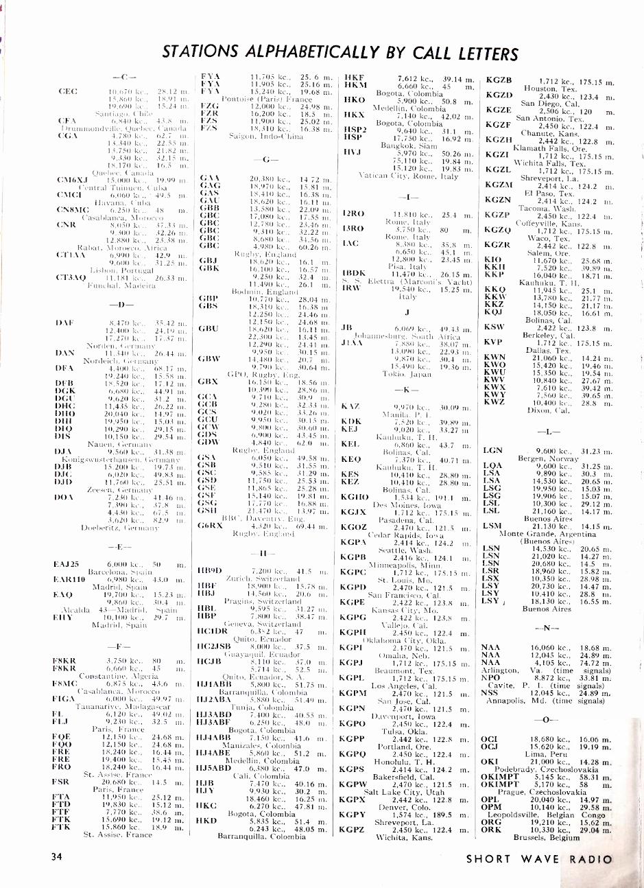
STATIONS ALPHABETICALLY BY CALL LETTERS
-C- CEC 10,670 kc., 28.12 m.
15,860 kc., 18.91 in. 19.690 kc.. 15.24 tn.
Santiago, Chile CFA 6.840 kc.. 43.8 m. Drummondville, Quebec, Canada
CGA 4,780 kc., 62.7 tn. 13,340 kc.. 22.55 in. 13,750 kc., 21.82 rn. 9,330 kc., 32.15 in.
18,170 kc.. 16.5 in. Quebec, Canada
CM6XJ 15,000 kc., 19.99 m. Central Tuinucu. Cuba
(:MCI 6,060 kc., 49.5 m. Havana, Cuba
CN8MC 6,250 kc.. 48 m. Casablanca, Morocco
CNR 8,050 kc.. 37.33 m. 9,300 kc., 32.26 nt.
12,880 kc., 23.38 In. Rabat, Morocco. Africa
CTIAA 6,990 kc., 42.9 in. 9.600 kc., 31.25 in.
Lisbon, Portugal CT3AQ 11,181 kc., 26.33 m.
Funchal, Madeira
DAF
DAN
DFA
DFB DGK DGU DHC DI IO DIII DIQ DIS
-D- 8,47(1 kc., 35.42 in.
12.400 kc., 24.19 ni. 17,270 kc., 17.37 in.
Norden, ( ;erntany 11,3411 kc.. 26.44 m.
Nordeiclt, ( ;ertuany 4,400 kc., 68.17
19,240 kc., 18,520 kc.,
6,680 kc., 9,620 kc.,
11,435 kc., 20,040 kc., 19,950 kc., 10,290 kc., 10,150 kc., 29.54 in.
Nauen, Germany DJA 9,560 kc., 31.38 m.
Konigswttsterhauseu, Germany D.iB 15.200 kc., 19.73 In. DJC 6,020 kc., 49.83 ni. DJD 11,760 kc., 25.51 in.
Zeesen, Germans' DOA 7,230 kc., 41.46 In.
7,390 kc., .i 7 .8 tn. 4,430 kc., 67.5 in. 3,620 kc., 82.9 III.
Doeberitz, Germany
15.58 17.12 44.91 31.2 26.22 14.97 15.03 29.15
nt.
nI. tn.
In.
m. nl. In. tn. m.
EAJ25 6,000 kc., 50 m. Barcelona, Spain
EAR110 6,980 kc., 43.0 m. Madrid, Spain
EAQ 19,700 kc., 15.23 tn. 9,860 kc., 30.4 ni.
Alcalda 43- Madrid, Spain EHY 10,100 kc., 29.7 m.
Madrid, Spain
-F- F8KR 3,750 kc., 80 In. F8KR 6,660 kc., 45 in.
Constantine, Algeria F8MC 6,875 kc., 43.6 m.
Casablanca, Morocco FIGA 6,000 kc., 49.97 In.
Tananarive, Madagascar FL 6,120 kc., 49.02 In. FLJ 9,230 kc., 32.5 m.
Paris, France FQE 12,150 kc.. 24.68 m. F00 12,150 kc., 24.68 m. FRE 18,240 kc., 16.44 m. FRE 19,400 kc., 15.45 m. FRO 18,240 kc., 16.44 m.
St. Assise, France FSR 20,680 kc., 14.5 m.
Paris, France FTA 11,950 kc., 25.12 m. FTD 19,830 kc., 15.12 m. FTF 7,770 kc., 38.6 m. FTK 15,690 kc., 19.12 m. FTK 15.860 kc.. 18.9 m.
St. Assise, France
FYA 11,705 kc., 25. 6 m. FYA 11,905 kc., 25.16 m. FYA 15,240 kc., 19.68 m.
Pontoise (Paris) France FZG 12,000 kc., 24.98 ni. FZR 16,200 kc.. 18.5 ni. FZS 11,900 kc., 25.02 m. FZS 18,310 kc.. 16.38 m.
Saigon, Indo-China
GAA GAG GAS GAU GBB GBC GBC GBC GBC GBC
GBJ GBK
GBP GBS
GBU
GBW
GBX
GCA GCB GCS GCU GCW GDS GDW
-G- 20,380 kc., 14.72 18,970 kc., 15.81 18,410 kc., 16.38 18,620 kc., 16.11 13,580 kc., 22.09 17,080 kc., 17.55 12,780 kc., 23.46 9,310 kc., 32.22 8,680 kc., 34.56 4.980 kc.. 60.26
Rugby, En..;land 18,620 kc., 16.1 16,100 kc., 16.57 9,250 kc., 32.4
11,490 kc., 26.1 Bodntin, England
1u.; 70 kc., 28.04 18i10 kc., 12,250 kc., 12,150 kc., 18,620 kc., 22,300 kc., 12,290 kc., 9,950 kc.,
14,480 kc., 9,790 kc..
GPO, Rugby, Eng. 16,150 kc., 18.56 10.390 kc., 28.86 9,710 kc., 30.9 9,280 kc., 32.33 9.020 kc., 33.26 9,950 kc., 30.15 9,800 kc., 30.60 m. 6.900 kc., 43.45 tn. 4,840 kc., 62.0 m.
Rugby, England GSA 6,050 kc., 49.58 m. GSB 9,510 kc., 31.55 m. GSC 9,585 kc., 31.29 m. GSD 11,750 kc., 25.53 m. GSE 11,865 kc., 25.28 m. GSF 15,140 kc., 19.81 m. GSG 17,770 kc., 16.88 nI. GSII 21,470 Lc.. 13.97 m.
BB(', Dayentry. Eng. G6RX 4,320 kc., 69.44 tn.
Rugby, England
m. m. m. In .
ni. m. m. m. m. ni.
tn. In. III.
m.
m. 16.38 in 24.46 in. 24.68 m. 16.11 m. 13.45 24.41 30.15 20.7 30.64
m. m. m. m. m.
m. m. tn. In. In. ni.
-H- 1169D 7,200 kc., 41.5 m.
Zurich, Switzerland HBF 18,900 kc., 15.78 m. IIBJ 14,560 kc., 20.6 m.
Pragins, Switzerland HBL 9,595 kc., 31.27 m. IIBP 7,800 kc., 38.47 m.
Geneva, Switzerland HC1DR 6,32 kc., 47 m.
Quito, Ecuador HC2JSB 8,000 kc., 37.5 m.
Guayaquil, Ecuador HCJB 8,110 kc., 37.0 m.
5,714 kc., 52.5 tn. Quito, Ecuador, S. A.
HJ1ABB 5,800 kc., 51.75 m. Barranquilla, Colombia
HJ2ABA 5,880 kc., 51.49 M. Tunja, Colombia
HJ3ABD 7,400 kc., 40.55 nt. HJ3ABF 6,250 kc., 48.0 m.
Bogota, Colombia IIJ4ABB 7.150 kc., 41.6 in.
Manizales, Colombia HJ4ABE 5,860 kc., 51.2 m.
Medellin. Colombia HJ5ABD 6,380 kc., 47.0 m.
Cali, Colombia HJB 7,470 kc., 40.16 m. HJ Y 9,930 kc., 30.2 m.
18,460 kc., 16.25 m. HKC 6,270 kc.. 47.81 m.
Bogota, Colombia HKD 5,835 kc., 51.4 m.
6,243 kc., 48.05 m. Barranquilla, Colombia
HKF HKM
HKO
HKX
HSP2 HSP
HVJ
7,612 kc., 39.14 m. 6,660 kc., 45 m.
Bogota, Colombia 5,900 kc., 50.8 m.
Medellin, Colombia 7,140 kc., 42.02 m.
Bogota, Colombia 9,640 kc., 31.1 m.
17.750 kc., 16.92 m. Bangkok, Siam
5,970 kc., 50.26 m. 75,110 kc., 19.84 m. 15.120 kc., 19.83 m.
Vatican City, Rome, Italy
-I-
12R0 11.810 kc., 25.4 m. Rome. Italy
I3R0 3,750 kc., 80 m. Rome, Italy
I AC 8,380 kc. 35.8 m. 6,650 kc., 45.1 m.
12,800 kc.. 23.45 m. Pisa, Italy
IBDK 11,470 kc., 26.15 m. S. S. Elettra (Marconi's Yacht) IRW 19,540 kc., 15.25 m.
Italy
J
JB 6,069 kc., 49.43 m. Johannesburg, South Africa
J1AA 7.880 kc., 38.07 m. 13,090 kc., 22.93 m. 9,870 kc., 30.4 m.
15,490 kc.. 19.36 m. Tokio, Japan
-K- K 1Z 9,970 kc., 30.09 m.
Manila, P. 1. KOK 7,520 kc., 39.89 m. KEJ 9,020 kc., 33.27 ni
Kauhuku, T. H. KEL 6.860 kc., 43.7 m.
Bolinas, Cal. KEQ 7,370 kc., 40.71 m.
Kauhuktt, T. H. KES 10,410 kc., 28.80 m. KEZ 10,410 kc., 28.80 tn.
Bolinas, Cal. KGHO 1,534 kc., 191.1 m.
Des Moines, Iowa KGJX 1,712 kc., 175.15 m.
Pasadena, Cal. KGOZ 2,470 kc., 121.5 in.
Cedar Rapids, Iooi a KGPA 2,414 kc., 124.2 m.
Seattle, Wash. KGPB 2,416 kc., 124.1 m.
Minneapolis, Minn. KGPC 1,712 kc., 175.15 ni.
St. Louis, Mo. KGPD 2,470 kc., 121.5 m.
San Francisco, Cal. KGPE 2,422 Icc., 123.8 m.
Kansas City, Mo. KGPG 2,422 kc., 123.8 m.
Vallejo, Cal. KGPH 2,450 kc., 122.4 m.
Oklahoma City, Okla. KGPI 2,470 kc., 121.5 m.
Omaha, Neb. KGPJ 1,712 kc., 175.15 m.
Beaumont, Tex. KGPL 1,712 kc., 175.15 m.
Los Angeles, Cal. KGPM 2,470 kc., 121.5 m.
San Jose, Cal. KGPN 2,470 kc., 121.5 ni.
Davenport, Iowa KGPO 2,450 kc., 122.4 m.
Tulsa, Okla. KGPP 2.442 kc., 122.8 ni.
Portland, Ore. KGPQ 2,450 kc., 122.4 m.
Honolulu, T. H. KGPS 2,414 kc., 124.2 m.
Bakersfield, Cal. KGPW 2,470 kc., 121.5 rn.
Salt Lake City, Utah KGPX 2,442 kc., 122.8 m.
Denver, Colo. 1,574 kc., 189.5 m.
Shreveport, La. 2,450 kc., 122.4 m,
Wichita. Kans.
KGPY
KGPZ
KGZB 1,712 kc., 175.15 m. Houston, Tex.
KGZD 2,430 kc., 123.4 m. San Diego, Cal.
KGZE 2,506 kc., 120 m. San Antonio, Tex.
KGZF 2,450 kc., 122.4 m. Chanute, Kans.
KGZH 2,442 kc., 122.8 in. Klamath Falls, Ore.
KGZI 1,712 kc., 175.15 m. Wichita Falls, Tex.
KGZL 1,712 kc., 175.15 m. Shreveport, La.
KGZM 2,414 kc., 124.2 ni. El Paso, Tex.
KGZN 2,414 kc., 124.2 m. Tacoma, Wash.
KGZP 2,450 kc., 122.4 m. Coffeyville, Kans.
KGZQ 1,712 kc., 175.15 ni. Waco, Tex.
KGZR 2,442 kc., 122.8 m. Salem, Ore.
KIO 11,670 kc., 25.68 ni. KKH 7,520 kc., 39.89 m. KKP 16,040 kc., 18.71 m.
Kauhuku, T. H. KKQ 11,945 kc., 25.1 m. KKW 13,780 kc., 21.77 m. KKZ 14,150 kc., 21.17 m. KQJ 18,050 kc., 16.61 m.
Bolinas, Cal. KSW 2,422 kc., 123.8 m.
Berkeley, Cal. KVP 1,712 kc., 175.15 m.
Dallas, Tex. KWN 21,060 kc., 14.24 ni. KWO 15,420 kc., 19.46 m. KWU 15,350 kc., 19.54 m. KWV 10,840 kc., 27.67 m. KWX 7,610 kc., 39.42 m. KWY 7,560 kc., 39.65 m. KWZ 10,400 kc., 28.8 m.
Dixon, Cal.
-L- LGN . 9,600 kc., 31.23 m.
Bergen, Norway LQA 9,600 kc., 31.25 m. LSA 9,890 kc., 30.3 m. LSA 14,530 kc., 20.65 m. LSG 19,950 kc., 15.03 m LSG 19,906 kc., 15.0.7 m LSL 10,300 kc., 29.12 m LSL 21,160 kc., 14.17 ni
Buenos Aires LSM 21,130 kc., 14.15 m.
Monte Grande, Argentina (Buenos Aires)
LSN 14,530 kc., 20.65 m. LSN 21,020 kc., 14.27 m. LSN 20,680 kc., 14.5 m. LSR 18,960 kc., 15.82 m. LSX 10,350 kc., 28.98 m. LSY 20,730 kc., 14.47 m. LSY 10,410 kc., 28.8 m. LSY j 18,130 kc., 16.55 m.
Buenos Aires
-N- NAA 16,060 kc., 18.68 m. NAA 12,045 kc., 24.89 m. NAA 4,105 kc., 74.72 in. Arlington, Va. (time signals) NPO 8,872 kc., 33.81 m:
Cavite, P. I. (time signals) NSS 12,045 kc., 24.89 m.
Annapolis, Md. (time signals)
-O- OCI 18,680 kc., 16.06 m. OCJ 15,620 kc:, 19.19 m.
Lima, Peru OKI 21,000 kc., 14.28 m.
Podebrady, Czechoslovakia OKIMPT 5,145 kc., 58.31 m. OKIMPT 5,170 kc., 58 m.
Prague, Czechoslovakia OPL 20,040 kc., 14.97 m. OPM 10,140 kc., 29.58 m.
Leopoldsville, Belgian Congo ORG 19,210 kc., 15.62 m. ORK 10,330 kc., 29.04 m.
Brussels, Belgium
34 SHORT WAVE RADIO
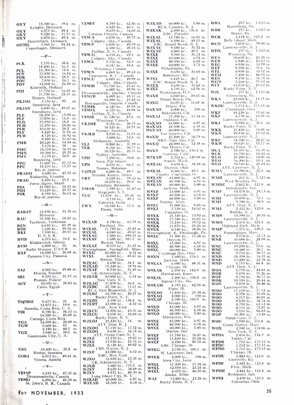
OXY 15,300 kc., 19.6 m. Lyngby, Denmark
OXY 6,075 kc., 49.4 m. OXY 9,520 kc., 31.51 ni. OXY 6,070 kc., 49.4 m.
Skamleback, Denmark OZ7RL 3,560 kc., 84.24 m.
Copenhagen, Denmark
-P- PCK 7,770 kc., 38.6
18,400 kc., 16.3 PCL 16,300 kc., 18.4 PCV 17,830 kc., 16.82 PDK 10,410 kc., 28.8 PDU 7,830 kc., 38.3 PDV 12,060 kc., 24.88
Kootwijk, Holland PHI 17,770 kc., 16.88
11,730 kc., 25.57 Huizen, Holland
PK2AG 3,156 kc., 95 m. Samarang, Java
PK3AN 6,040 kc., 49.67 m. Sourabaya, Java
PLE 18,200 kc., 15.94 PLF 17,850 kc., 16.8 PLG 15,950 kc., 18.8 PLM 12,250 kc., 24.46 PLR 10,630 kc., 28.2 PLV 9,420 kc., 31.86 PLW 8,120 kc., 36.92
9,480 kc., 31.63 PMB 20,620 kc., 14.54
5,170 kc., 58 PMC 18,370 kc., 16.33 PMN 10,360 kc., 29.25 PMY 5,170 kc., 58.0
Bandoehg, Java PPG 11,660 kc., 27.73 PPU 19,270 kc., 15.57
Rio de Janeiro PRADO 6,620 kc., 45.31 ni.
Riobamba, Ecuador PRAG 8,450 kc., 35.5 m.
Porto Algero, Brazil PSA 21,080 kc., 14.23 PSH 10,220 kc., 29.35 PSK 8,190 kc., 36.65
Rio de Janeiro
m. nt.
m. m. m. ni.
nl.
nl.
m. ni. m. n. m. m. ni. n. m. m. m. ni.
m.
n. m.
-R- RABAT 12,830 kc., 23.38
Morocco RAU 15,100 kc., 19.85
Tachkent, Turkestan REN 6,610 kc., 45.38 RIM 7,630 kc.. 39.34 RKI 7,500 kc., 39.97
U. S. S. R. RVI5 4,273 kc., 70.2
Khabarovsk, Siberia RV59 6,000 kc., 50
Radio Moscow, U.S.S.R. RXF 14,500 kc., 20.69
Panama City, Panama
-S- 6,065 kc., 49.46 m.
Motola, Sweden 9,570 kc., 31.35 m.
Poznan, Poland 10,050 kc., 29.83 m.
Cairo, Egypt
SAJ
SRI
SUV
m. ni. n.
ni.
ni.
m. m. m.
m.
m.
m.
-T- T14NRH 9,675 kc., 31
15,075 kc., 19.9 Heredia, Costa Rica, C. A.
TIR 8,790 kc., 34.13 m. 14,500 kc., 20.69 m.
Cartago, Costa Rica TGA 14,500 kc., 20.69 m. TGW 6,660 kc., 45 m.
6,180 kc., 48.5 m. TGX 5,940 kc., 50.5 m.
Guatemala City, C. A.
m. m.
-U- UIG 10,400 kc., 28.8 m.
Medan, Sumatra UOR2 6;072 kc., 49.41 m.
Vienna, Austria
-V- VE9AP 6,335 kc., 47.35 m.
Drummondville, Canada VE9BJ 6,090 kc., 49.29 m.
St. John's, N. B., Canada
VE9BY 4,795 kc., 62.56 m, 6,425 kc., 46.7 m. 8,650 kc., 34.68 nl.
London, Ontario, Canada VE9CA 6,030 kc., 49.75 tn.
Calgary, Alta., Canada VE9CF 6,050 kc., 49.59 ni.
6,100 kc., 49.15 m. Halifax, N. S., Canada
VE9CG 6,110 kc., 49.1 m. Calgary, Alta., Canada
VE9CL 5,710 kc., 52.5 ni. 6,147 kc., 48.8 tn.
Winnipeg, Canada VE9CS 6,069 kc., 49.43 m.
Vancouver, B. C., Canada VE9CU 6,005 kc., 49.99 m.
Calgary, Alta., Canada VE9DR 11,780 kc., 25.47 m.
6,005 kc., 49.96 m. Drummondville, Quebec, Canada VE9GW 6,095 kc., 49.17 ni.
11,800 kc., 25.42 m. Bowmanville, Ontario, Canada
VE9I -IK 6,120 kc., 48.98 ni. VE9HX 6,125 kc., 48.98 in.
Halifax, N. S., Canada VE9JR 11,720 kc., 25.6 m.
Winnipeg, Canada VK2ME 9,760 kc., 30.75 m.
10,520 kc., 28.51 m. Sydney, Australia
VK3LR 9,510 kc., 31.55 ni. 5,680 kc., 52.8 in.
Melbourne, Australia VLJ 9,980 kc., 37.59 m. VLK 9,760 kc., 30.75 m.
10,520 kc., 28.51 m. Sydney, Australia
VPD 7.890 kc.. 38.0 m. Suva, Fiji Islands
VPN 4,510 kc., 66.5 ni. Nassau, Bahamas
VQ7LO 6,000 kc., 49.5 m. Nairobi, Kenya, Africa
VRT 5,050 kc., 59.42 ni. 10,070 kc.. 29.8 ni.
Hamilton, Bermuda VSIAB 7,195 kc., 41.67 ni.
Singapore, S. S. VUC 11.870 kc., 25.26 in.
6,110 kc., 49.1 ni. Calcutta, India
VWY 18,540 kc., 17.1 m. Poona, India
-W- W1XAB 4,700 kc., 63.79 m.
Portland, Me. W1XAL 11,790 kc., 25.45 ni W1XAL 6,040 kc., 49.67 m. W1XAU 1,560 kc., 199.35 m. W1XAV 1,600 kc., 187.5 m.
Boston, Mass. W1XAZ 9,570 kc., 31.35 m. Westinghouse, Springfield, Mass. W1XG 43,000 kc., 6.52 m. W1XL 6,040 kc., 49.67 m.
Boston, Mass. W2XAC 8,690 kc., 34.5 m. W2XAD 15,340 kc., 19.56 ni. W2XAF 9,530 kc., 31.48
GE, Schenectady, N. V. W2XAK 43,000 kc., 6.52 m.
New York, N. V. W2XAO 17.850 kc., 16.8 ni. W2XBC 25,700 kc., 11.67 m.
RCA, New Brunswick, N. J. W2XBJ 14,700 kc., 20.27 m.
Rocky Point, N. Y. W2XBS 2,100 kc., 136.4 in. W2XBT 43,000 kc., 6.52 in.
NBC, New York W2XCU 12,850 kc., 23.35 m. W2XCU 8,650 kc., 34.68 m.
Rocky Point, N. Y. W2XDJ 21,420 kc., 14. m.
ATT, Deal, N. J. W2XDO 17,110 kc., 17.52 m. W2XDO 8,630 kc., 34.74 m.
ATT, Ocean Gate, N. J. W2XE 15.270 kc., 19.65 m. W2XE 11,830 kc., 25.36 m. W2XE 6,120 kc., 49.02 m.
CBS, Wayne, N. J. W2XF 43,000 kc., 6.52 m.
NBC, New York W2XO 12,850 kc., 23.35 m.
GE, Schenectady, N. Y. W2XR 1,600 kc., 176.5 m. W2XV 8,650 kc., 34.68 m. W2XV 4,975 kc., 60.30 m.
Long Island City, N. Y. W3XAD 43,000 kc., 6.97 m. W3XAD 48,500 kc., 6.18 m ,
W3XAD 60,000 kc., 5.00 m, RCA, Camden, N. J.
W3XAK 2,100 kc., 136.4 m. NBC, Portable
W3XAL 17,780 kc., 16.87 m. W3XAL 6,100 kc., 49.15 m.
NBC, Bound Brook, N. J. W3XAU 9,580 kc., 31.32 m. W3XAU 6,060 kc., 49.5 nt. W3XE 9,580 kc., 31.32 ni. W3XE 43,000 kc., 6.52 m. W3XE 48,500 kc., 6.00 m. W3XE 60,000 kc., 3.75 m.
Philadelphia, Pa. W3XE 8,650 kc., 34.68 tn.
Baltimore, Md. W3XL 6,425 kc., 46.7 ni.
NBC, Bound Brook, N. J. W3XX 8,650 kc., 34.68 m. W3XZ 4,795 kc., 62.56 m.
Washington, D. C. W4XB 6,040 kc., 49.67 m.
Miami Beach, Fla. W4XG 8,650 kc., 34.68 in.
Miami, Fla. W6XAH 2,000 kc., 150 ni.
Bakersfield, Cal. W6XAJ 17,300 kc., 17.34 m.
Oakland, Cal. W6XAO 43,000 kc., 6.97 m. W6XAO 48,500 kc., 6.18 ni. W6XAO 60,000 kc., 5.00 in.
Los Angeles, Cal. W6XD 27,800 kc., 10.79 nm.
MRT, Palo Alto, ('al. W6XQ 24,000 kc., 12.48 m.
San Mateo, Cal. W6XS 2.100 kc., 136.4 in.
Gardena, Calif. W7XAW 2,342 kc., 128.09 in.
Seattle, Wash. W8XAG 8,650 kc., 34.68 m.
Dayton. Ohio W8XAL 6,060 kc., 49.5 tn.
Crosley, Cincinnati, O. W8XAN 43,000 kc., 6.97 in. W8XAN 48,500 kc., 6.18 nr. W8XAN 60,000 kc., 5.00 in.
Jackson, Mich. \\ 8XF 43,000 kc., 6.97 m. W8XF 48,500 kc.. 6.18 ni. W8XF 60,000 kc., 5.00 ni.
Pontiac, Mich. \ %'8XI 31,000 kc., 9.68 in. WRXJ 5,550 kc., 54.02 m.
Columbus, O. W8XK 21,540 kc., 13.93 m. W8XK 17,780 kc., 16.87 m. W8XK 15,210 kc., 19.72 m. W8XK 11,870 kc., 25.26 m. W8XK 6,140 kc., 48.86 in. Westinghouse, E. Pittsburgh, Pa. W8XL 17,300 kc., 17.34 m.
Dayton, O. W8XL 43,000 kc., 6.97 ni. W8XL 48,500 kc., 6.18 m. W8XL 60,000 kc., 5.00 m.
Cuyahoga Hts., Ohio W8XN 1,600 kc.. 176.5 tn.
Jackson, Mich. W9XAA 6.080 kc., 49.31 m.
Chicago, Ill. W9XAK 2,100 kc., 142.9 m.
Manhattan, Kans. W9XAL 2,200 kc., 136.4 m.
Kansas City, Mo. W9XAM 4,795 kc., 62.56 m.
Elgin, Ill. W9XAO 11,840 kc., 25.34 m. W9XAO 2,000 kc., 150 m. W9XAP 2,100 kc., 142.9 m.
Chicago, Ill. W9XD 43,000 kc., 6.97 m. W9XD 48,500 kc., 6.18 m. W9XD 60,000 kc., 5.00 m.
Milwaukee, Wis. W9XE 43,000 kc., 6.97 m. W9XE 48,500 kc., 6.18 m. W9XE 60,000 kc., 5.00 nt.
Marion, Ind. W9XF 17,780 kc., 16.87 m. W9XF 11,880 kc., 25.24 m. W9XF 6,100 kc., 49.18 m.
NBC, Chicago, Ill. W9XG 2,750 kc., 109.1 m.
W. Lafayette, Ind. W9XK 2,000 kc., 150 m.
Iowa City, Iowa W9XL 17,300 kc., 17.34 m. W9XL 12,850 kc., 23.35 m. W9XL 6,425 kc., 46.70 m.
Anoka, Minn. WAJ 13,480 kc., 22.26 m.
Rocky Point, N. Y.
WBA 257 kc., 1,123 m. I-Iarrisbnrg, Pa.
WBR 257 kc.. 1.123 m. Butler. Pa.
WCK 2,414 kc., 121.2 nl. Belle kland, Mich.
WCN 5.070 kc.. 59.08 nt. Lawrenceville. N..1.
WDX 257 kc., 1,123 nt. Wyoming, Pa.
WEA 10.610 kc., 28.28 m. WEB 6,940 kc., 43.23 in. WEG 8.930 kc.. 33.59 in. WEF 9,590 kc.. 31.6 ni. WEL 8.950 kc.. .33.52 nt. WEM 7.400 kc.. 40.54 m. WES 9,450 kc., 31.74 in. WGN 5.260 kc., ;7.03 nr. WIY 13,870 kc.. 21.63 in.
Rocky l'oint, N. \'. WJL 257 kc., 1.123 in.
Green,,l)IIr'g, Pa. WKA 21.060 kc., 14.25 in.
Lawrenceville. N. J WKDU 1,712 kc.. 175.15 in.
Cincinnati, Ohio WKF 19.220 kc., 15.61 rn. WKF 4.750 kc., 63.21 in.
Lawrenceville. N. J. WKJ 9.590 kc., 31.6 m.
Rocky Point, N. V. WKK 21.410 kc., 14.01 m. WKN 19.830 kc., 15.13 m.
Lawrenceville. N. 1.
WKU 14.7011 kc., 20.27 in. WKW 19,020 kc., 15.77 m.
Rocky l'oint. N. V. WLA 18..35(í kc., 16.35 ni. WLK 16.330 kc., 18.44 in. WLO 21.400 kc., 14.01 rn. WLO 16.300 kc.. 18.4 tn. WLO 1t1.54(1 kc.. 28.44 in.
ATT, Lawrence. N. J. \\'11A 13,390 k... 22.4 rn.
Lawrenceville. N. -1
.
W1\I13 267 kc.. 1,123 m. \\'dt Reading, Pa.
WM DZ 2,442 kc., 122.8 m. Indianapoli-. Ind.
WMF 14,4711 kc.. 20.73 m. Lawrenceville. N. J.
WMI 19.850 kc., 15.1 nt. WMI 9.700 kc., 30.9 tn.
ATT, Deal. N. J. WMJ 2,422 kc., 123.8 m.
Buffalo. N. J. WMN 14.590 kc.. 20.56 m.
Lawrenceville, N. J. WMO 2.414 kc., 124.2 m.
Highland Park, Mich. WMP 1.574 kc., 189.5 m.
Framingham. Mass. WNA 9,170 kc.. 32.72 m. WNB 10.680 kc., 28.09 in.
Lawrenceville. N. J. WNC 19,200 kc., 15.6 rn. WNC 14,480 kc.. 20.7 m. WNC 9,750 kc., 30.75 m. WND 18,350 kc., 16.35 m. WND 13,400 kc., 22.38 tn. WND 6,753 kc., 44.4 m.
ATT, Deal, N. J. WOA 6,750 kc., 44.41 m. WOB 5,850 kc., 51.26 m. WOF 9.750 kc., 30.77 m. WOK 10,550 kc., 28.44 m. WON 9,870 kc.. 30.40 m.
Lawrenceville, N. J. WOO 17,110 kc., 17.52 m. WOO 8,550 kc., 35.09 m. WOO 6,515 kc., 46.05 m. WOO 8.630 kc., 34.74 m. WOO 4.750 kc., 63.13 m. WOO 4,116 kc., 72.87 m. WOO 3.124 kc., 96.03 m. WOP 19,380 kc., 15.48 m.
Ocean Gate, N. J. WOU 2.590 kc., 115.8 m.
Green Harbor. Mass. WOX 2,54(1 kc., 118.06 m.
New York, N. V. WPDA 2,414 kc., 124.7. m.
Tulare. Cal. WPDB 1,712 kc., 175.15 m. WPDC 1,712 kc., 175.15 rn. WPDD 1,712 kc., 175.15 m.
Chicago. Ill. WPDE 2,442 kc., 122.8 m.
Louisville, Ky. WPDF 2,442 kc., 122.8 m.
Flint, Mich. WPDH 2,442 kc., 122.8 m.
Richmond, Ind. WPDI 2,430 kc., 123.4 m.
Columbus, Ohio
35 fc >r NOVEMBER, 1933
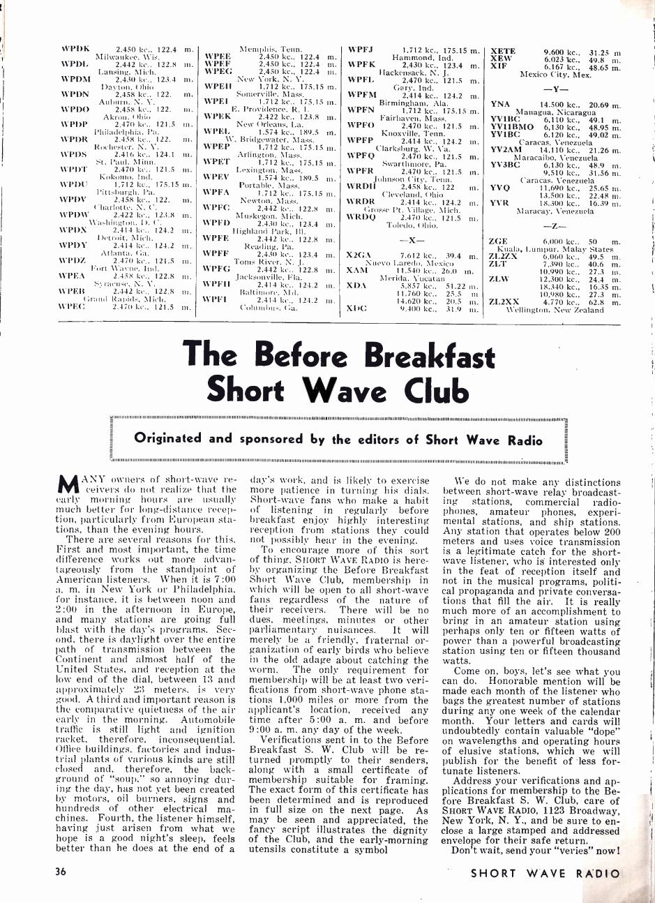
WPDK 2,450 kc., 122.4 m. Milwaukee. \Vis.
WPDI, 2.442 kc.. 122.8 m. Lansing. Mich.
WPDM 2,430 kc., 123.4 m. Dayton, Ohio
WPDN 2,458 kc., 122. m. Auburn, N. Y.
WPDO 2,458 kc., 122. tn. Akron. Ohio
WPDP 2,470 kc., 121.5 m. Philadelphia, Pa.
\VPDR 2,458 kc.. 122. m. Rochester, N. Y.
\VPDS 2,416 kc., 124.1 in. st. Paul, Minn.
W PDT 2,470 kc., 121.5 in. Kokomo, Incl.
WP DU 1 ,712 kc., 175.15 m. Pittsburgh, Pa.
1VPDV 2,4581:c., 122. m. Charlotte, N. C.
WPDW 2,422 kc.. 123.8 m. Washington. D. C.
WPDX 2.414 kc., 124.2 tn. Detroit. \1 ich.
\VPDY 2,414 kc., 124.2 m. Atlanta, Ga.
WPDI. 2.470 kc.. 121.5 m. Fort CWayne, Ind.
V 'PEA 2.45 t kc., 122.8 m. titracu'e. N. V.
1V PE 2.442 kc., 122.8 m. Grand Rapids, Mich.
\VPEC 2.47(1 kc., 121.5 m.
Memphis, Tenn. WPEE 2,450 kc., 122.4 m. WPEF 2,450 kc., 122.4 m. WPEG 2,450 kc., 122.4 m.
New York, N. V. WPEH 1,712 kc., 175.15 m.
Somerville, Mast, WPEI 1,712 kc.. 175.15 ni.
E. Providence, R. I. WPEK 2,422 kc., 123.8 m.
New Orleans, La. WPEL 1,574 kc., 189.5 m.
W. Bridgewater, Mass. WPEP 1,712 kc., 175.15 ni.
Arlington. Mass. WPET 1,712 kc., 175.15 m.
Lexington, Mass. WPEV 1,574 kc., 189.5 m.
Portable, Mass. WPFA 1,712 kc., 175.15 ni.
Newton, Mass. WPFC 2,442 ke.. 122.8 ni.
Muskegon. Mich. WPFD 2,430 kc., 123.4 m.
Highland Park, Ill. WPFE 2,442 kc., 122.8 m.
Reading. Pa. WPFF 2,430 kc.. 123.4 m.
Toms River, N. J. WPFG 2,442 kc.. 122.8 ni.
Jacksonville, Fla. WPFII 2,414 kc.. 124.2 m.
Baltimore. 1lrl. WPFI 2.414 kc., 124.2 in.
Columbus. Ga.
WPFJ 1.712 kc., 175.15 m. Hammond, Ind.
WPFK 2,430 kc., 123.4 m. Hackensack, N. J.
WPFL 2,470 kc., 121.5 m. Gary, Ind.
WPFM 2,414 kc., 124.2 m. Birmingham, Ala.
WPFN 1,712 kc., 175.15 m. Fairhaven, Mass.
WPFO 2,470 kc., 121.5 m. Knoxville, Tenn.
WPFP 2,414 kc., 124.2 m. Clarksburg. W. Va.
WPFQ 2.470 kc., 121.5 m. Swarthmore, Pa.
WPFR 2,470 kc., 121.5 m. Johnson City. Tenn.
WRDH 2,458 kc., 122 ni. Cleveland, Ohio
WRDR 2.414 kc., 124.2 m. (:rosse Pt. Village, Mich.
WRDQ 2,470 kc., 121.5 m. Toledo, Ohio.
-X- X2GA 7,612 kc., 39.4 m.
Nuevo Laredo. Mexico XAM 11,540 kc., 26.0 m.
Merida. Yucatan XDA 5,857 kc., 51.22 m.
11,760 kc., 25.5 in 14,620 kc., 20.5 m. XIC 9,400 kc., 31.9 m.
XETE 9,600 kc.. 31.25 ni XEW 6,0231cc., 49.8 m. XIF 6,167 kc., 48.65 m.
Mexico City, Mex.
-Y- YNA 14,500 kc., 20.69 m.
Managua, Nicaragua YV1BC 6,110 kc., 49.1 m. YV1IBMO 6,130 kc., 48.95 m. YV1BC 6,120 kc., 49.02 m.
Caracas, Venezuela YV2AM 14,110 kc., 21.26 m.
Maracaibo, Venezuela YV3BC 6,130 kc., 48.9 m.
9,510 kc., 31.56 m. Caracas, Venezuela
YVQ 11,690 kc., 25.65 m. 13.500 kc., 22.48 m.
YVR 18,300 kc., 16.39 m. I\Iaracay, Venezuela
-Z- ZGE 6,000 kc., 50 m.
Kuala, Lumpur, Malay States ZL2ZX 6,060 kc., 49.5 ni. ZLT 7,390 kc., 40.6 m.
10,990 kc., 27.3 ni. ZLW 12,300 kc., 24.4 m.
18.340 kc., 16.35 m. 10,980 kc., 27.3 m.
ZL2XX 4,770 kc., 62.8 ni. Wellington, New Zealand
The Before Breakfast Short Wave Club
.4i I I I I il MI I I I I I I I I I I I I I I I I I I II I I I I II I I II II I I I11II,I II II I I I I I II I11111111II I I II111111I I I II II1 1 1 1 1 1 1II II II II I III III II I II II II IIIIIIII I I I IIIII II II II I I I I III II I1I I I I II II II II IIIII1111111II II IIIIII,I,IIIII-III III II1111111II1111111IIII IIII I II II I II II II I II II III II I II I I II III III IIIIIIIIY
, l l I l l l l 111111111111111111I111I I I I I I I I I I I I I I I l l l l l l l l l l l l l l l l I I I I l l l l I I I I I I I111I I I I I I I I I I I I I l l I I I I I l l l I II I I I I I I I I l l 111111II1111II I I II I I111 l l l l l l II I I I1I I I I I I I I I111I I I I II1I l 111II ll I I I Il l l l l l l II I I I I I I II I1111111111I111 I 11l 11111 ll l I I I I I II II I I I II1111III II III IIIII1111111III I I I I I.'
Originated and sponsored by the editors of Short Wave Radio
MANY owners of short -wave re- ceivers do not realize that the
early morning hours are usually much better for long -distance recep- tion, particularly from European sta- tions, than the evening hours.
There are several reasons for this. First and most important, the time difference works out more advan- tageously from the standpoint of American listeners. When it is 7:00 a. m. in New York or Philadelphia, for instance, it is between noon and 2:00 in the afternoon in Europe, and many stations are going full blast with the day's programs. Sec- ond, there is daylight over the entire path of transmission between the Continent and almost half of the United States, and reception at the low end of the dial, between 13 and approximately 23 meters, is very good. A third and important reason is the comparative quietness of the air early in the morning. Automobile traffic is still light and ignition racket, therefore, inconsequential. Office buildings, factories and indus- trial plants of various kinds are still closed and, therefore, the back- ground of "soup," so annoying dur- ing the day, has not yet been created by motors, oil burners, signs and hundreds of other electrical ma- chines. Fourth, the listener himself, having just arisen from what we hope is a good night's sleep, feels better than he does at the end of a
36
day's work, and is likely to exercise more patience in turning his dials. Short -wave fans who make a habit of listening in regularly before breakfast enjoy highly interesting reception from stations they could not possibly hear in the evening.
To encourage more of this sort of thing, SHORT WAVE RADIO is here- by organizing the Before Breakfast Short Wave Club, membership in which will be open to all short -wave fans regardless of the nature of their receivers. There will be no dues, meetings, minutes or other parliamentary nuisances. It will merely be a friendly, fraternal or- ganization of early birds who believe in the old adage about catching the worm. The only requirement for membership will be at least two veri- fications from short -wave phone sta- tions 1,000 miles or more from the applicant's location, received any time after 5 :00 a. m. and before 9 :00 a. m. any day of the week.
Verifications sent in to the Before Breakfast S. W. Club will be re- turned promptly to their senders, along with a small certificate of membership suitable for framing. The exact form of this certificate has been determined and is reproduced in full size on the next page. As may be seen and appreciated, the fancy script illustrates the dignity of the Club, and the early- morning utensils constitute a symbol
We do not make any distinctions between short -wave relay broadcast- ing stations, commercial radio- phones, amateur phones, experi- mental stations, and ship stations. Any station that operates below 200 meters and uses voice transmission is a legitimate catch for the short- wave listener, who is interested only in the feat of reception itself and not in the musical programs, politi- cal propaganda and private conversa- tions that fill the air. It is really much more of an accomplishment to bring in an amateur station using perhaps only ten or fifteen watts of power than a powerful broadcasting station using ten or fifteen thousand watts.
Come on, boys, let's see what you can do. Honorable mention will be made each month of the listener who bags the greatest number of stations during any one week of the calendar month. Your letters and cards will undoubtedly contain valuable "dope" on wavelengths and operating hours of elusive stations, which we will publish for the benefit of less for- tunate listeners.
Address your verifications and ap- plications for membership to the Be- fore Breakfast S. W. Club, care of SHORT WAVE RADIO, 1123 Broadway, New York, N. Y., and be sure to en- close a large stamped and addressed envelope for their safe return.
Don't wait, send your "veries" now 1
SHORT WAVE RADIO
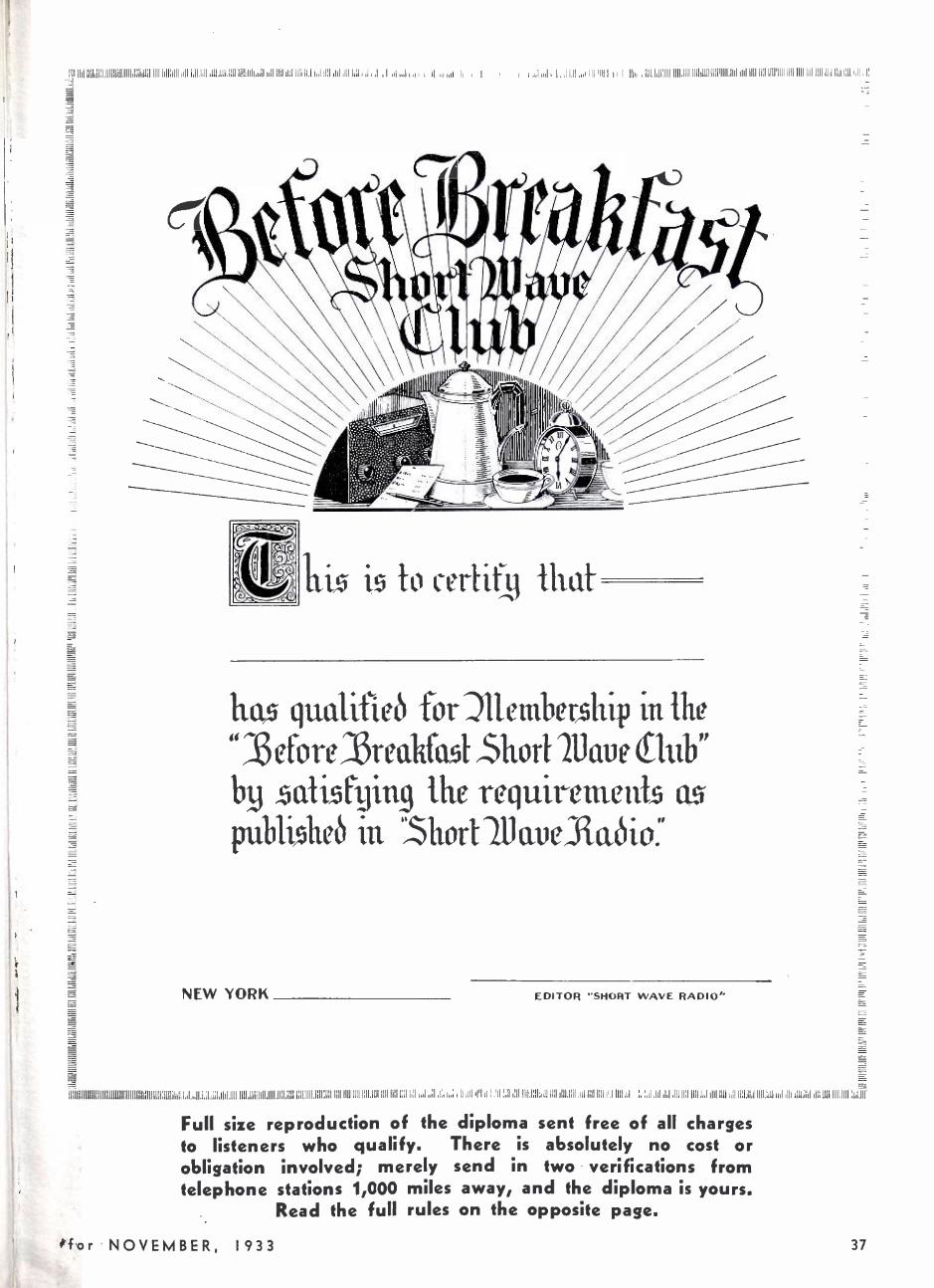
111111ìf,Illllil:liIIIIIIiIli1111I1iL1111 IIIfIì111111LÜ11'iY1.ld1 111.i,;I ... ;11.. 'J111111111:IIII'IIII!IIII!IIII!IIIIJId1ü11i1111111111'1111.11111111:1111 IIII III d III II ,i!
ix i5 certify Mat
ha qualificò forJllcmbcrship in the
"îßefore i3reakfa,51 Short Naue flub" bB al g the requiremeiiTs publißhcô in 1$hort111avcJTaóio'
NEW YORK EDITOR "SHORT WAVE RADIO"
1811111111111111111111111111111111111111iI111111Í 11161i1' ;; !;Li J iüllllll!IIIIJIII IIIIiIIII;IIIFIIII iIII IJI, '"II'' !I i!, '! ;: I" I'''1
Full size reproduction of the diploma sent free of all charges to listeners who qualify. There is absolutely no cost or obligation involved; merely send in two verifications from telephone stations 1,000 miles away, and the diploma is yours.
Read the full rules on the opposite page.
for NOVEMBER, 1933 37
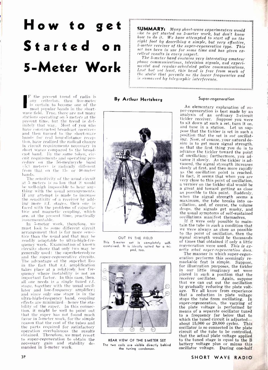
How to get Started on 5 -Meter Work
F the present trend of radio is any criterion, then five -meter is certain to become one of the most popular bands in the short-
wave field. True, there are not many stations operating on 5 meters at the present time, but the trend is def- initely that way. Most of you wir, have constructed broadcast receivers and then turned to the short -wave bands for real long- distance recep- tion, have realized the radical change in circuit requirements necessary in short waves compared to the broad- cast band. By the same token, cir- cuit requirements and operating pro- cedure on the 56- megacycle band (5.3 meters ) is radically different from that on the 15- or 40 -meter bands.
The sensitivity of the usual circuit at 5 meters is so low that it would be well -nigh impossible to hear any- thing with the usual arrangements. If any attempt is made to increase the sensitivity of a receiver by add- ing more r.f. stages, then one is faced with the problems of capacita- tive and magnetic coupling, which are, at the present time, practically insurmountable.
In 5 -meter work, therefore, wv, 1
must look to some different circuit arrangement that is far more sensi- tive than the usual and that may be readily adaptable to ultra- high -fre- quency work. Examination of known circuits shows that only two may be generally used : the superheterodyne and the super -regenerative circuits. The advantage of the superhet lies in the fact that r.f. amplification takes place at a relatively low fre- quency where instability is not an important factor. In this case, then. all one needs is a single tuned r.f. stage, together with the usual oscil- lator and low- frequency amplifier: and since only one stage is in the ultra- high- frequency band, coupling effects are minimized -hence the sta- bility of the super. In this connec- tion, it might be well to point out that the super has not found much favor in 5 -meter work, for the simple reason that the cost of the tubes and the parts required for satisfactory operation overbalances the results obtained. Therefore, we must resort to super -regeneration to obtain the necessary gain and stability de- manded in 5 -meter work.
3P
SUMMARY: Many short -wave experimenters would like to get started on 5 -meter work, but don't know 1. how to do it. We have attempted to start off on the right foot by describing a simple, but very effective, 5 -meter receiver of the super- regenerative type. This set has been in use for some time and has given ex- cellent results in every respect.
The 5- meter band contains very interesting amateur phone communications, television signals, and experi- mental and regular- scheduled police communications. Lust but not least, this band is free from much of the static that prevails on the lower frequencies and is unmarred by telegraphic interference.
: IIIIIIIIIIIIIIIIIIIIIIIIIIIIIIIIII mum II III Illlillllllllll111111111II III II III II II III III II III1111111111111111II II II111111II1111111II II111111111III II II III IIIII II II III IIIII1111111II
By Ar7hur Hertzberg
OUT IN THE FIELD This 5 -meter set is completely self - contained. It is ideally suited for a tri-
pod, too.
REAR VIEW OF THE 5 METER SET
The two coils are visible directly behind the tuning condenser.
Super- regeneration
An elementary explanation of su- per- regeneration is best made by an analysis of an ordinary 3- circuit tickler receiver. Suppose you were to sit down at such a set, turn it on, and tune in a station. Let us sup- pose that the tickler is set in such a position that the set is not oscillat- ing. Now, of course, your natural de- sire is to get more signal strength, so that the first thing you do is to advance the tickler toward the point of oscillation ; furthermore, you ad- vance it slowly. As the tickler is ad- vanced, the signal strength increases slowly at first, and then more rapidly as the oscillation point is reached. In fact, it seems that when you are very close to this point of oscillation, a vernier on the tickler dial would be a great aid toward getting as close as possible to this point. Suddenly, when the signal strength seems a maximum, the tube breaks into os- cillation, and, of course, the volume drops, the signals get mushy, and the usual symptoms of self- sustained oscillations manifest themselves.
If it were only possible to main- tain the tube in such a condition that we were always as close as possible to the point of oscillation, then the signal strength would be thousands of times that obtained if only a little regeneration were used. This is ex- actly what super- regeneration does.
The manner in which super- regen- eration performs this seemingly re- markable feat is simple. Suppose, for illustration purposes, the tickler in our little imaginary set were placed in such a position that the receiver oscillates. Again, suppose that we can cut out the oscillation by gradually reducing the plate volt -' age. We all know from experience that a reduction in plate voltage stops the tube from oscillating. In super- regeneration, the varying of the plate voltage is performed by means of a separate oscillator tuned to a frequency far below that to which the tuned circuit is adjusted - about 15,000 or 20,000 cycles. This oscillator is so connected in the plate circuit of the tube to be controlled, that the actual plate voltage applied to the tuned stage is equal to the B battery voltage plus or minus this oscillator voltage. During one -half
SHORT WAVE RADIO

of the oscillator cycle, the oscillator voltage adds to the plate voltage, making the tube oscillate, and on the other half of the cycle the oscillator voltage is bucking the steady plate voltage, making the tube stop oscil- lating.
The result is that when the oscil- lator voltage is aiding the B battery voltage, the tube starts to regener- ate ; but because the voltage is vari- able and starts to drop, the tube ac- tually does not have sufficient time to build up to the point where oscil- lation actually begins. In other words, during one -half of the oscil- lator cycle, regeneration is building up very close to the point of oscilla- tion, and on the other half of the cycle it is building down, so to speak. The tube, therefore, is always on the verge of oscillation, but is never ac- tually oscillating, so that we have satisfied our conditions for maximum response with good stability. This separate oscillator, commonly called a quencher, may, if so desired, be placed in the grid circuit, but the circuit is much more stable when connected in the plate circuit.
It is easily appreciated, now, that the greater the difference between the quenching frequency and the sig- nal frequency, the more stable the circuit; for if both were nearly the same, a.f. signals would be sure to develop, the circuits would tend to "pull" into synchronism, and the re- sult would be worse than if no quencher were used at all. That is another reason why super- regenera- tion works so well on ultra -high fre- quencies.
Our 5 -Meter Receiver The receiver to be described here
is not the finest that can be built, nor is it the worst. It is a receiver that has given excellent results and that is especially suitable for the man engaged in short -wave work who wants to know more about 5- meter stuff. Once the peculiarities of 5 -meter reception have been mas- tered, he may step ahead to more complicated and more sensitive sets.
The photographs and the diagrams illustrate completely the receiver it-
CI- Hammarlund postage -stamp trimmer. C2 -20 mmf. variable Hammarlund, MC-
20 -S. G3 -.000I mf. fixed condenser. C4 -.002 mf. fixed condenser. C5 -.002 mf. fixed condenser. RI -I megohm fixed resistor. R2 -I5 -ohm rheostat. TI- Quenching frequency oscillator coils
(F. W. Sickles Co.). T2- Hegehog audio transformer. J- Single open -circuit phone lack. R.F.C. -5 -meter R.F. choke. VI, V2, V3 -Type 30 tubes (Sylvania). 3-4 -prong Isolantite sockets (Hammarlund. SW. -Snap switch. I- Vernier dial (National type B). Bakelite or hard rubber 2 x 21/4 x 1/8" for
condenser mount. I-Insulated flexible coupling (Hammarlund). I -Front panel 73/4 x 63/4" aluminum -Blan
the Radio Man. I- Chassis 123/4 x 73/4" aluminum No. 14
gauge -Blan the Radio Man.
for NOVEMBER, 1933
THE 5 -METER RECEIVER IN A CAR AND IN THE FIELD
Its small size and the fact that the batteries are a part of the receiver itself make this set fit for a cor or for portable work in the field. The A and B batteries are
strapped to the receiver proper.
PICTORIAL WIRING DIAGRAM OF THE 5 -METER RECEIVER
The connections here are the same as those given in the schematic below.
SCHEMATIC CIRCUIT OF THE 3 -TUBE, 5 -METER RECEIVER
Complete schematic diagram of the set. Either the wiring diagram here or the point - to -point diagram above may be used to connect up this set. The list of parts is shown
to the left.
39
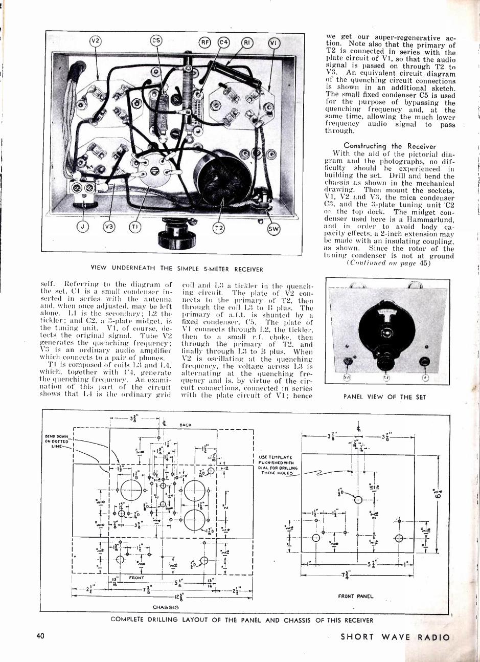
VIEW UNDERNEATH THE SIMPLE 5 -METER RECEIVER
self. Referring to the diagram of the set, Cl is a small condenser in- serted in series with the antenna and, when once adjusted, may be left alone. L1 is the secondary; L2 the tickler; and C2, a 3 -plate midget, is the tuning unit. Vi, of course, de- tects the original signal. Tube V2 generates the quenching frequency; V3 is an ordinary audio amplifier which connects to a pair of phones.
Ti is composed of coils L3 and L4, which, together with C4, generate the quenching frequency. An exami- nation of this part of the circuit shows that IA is the ordinary grid
coil and L3 a tickler in the quench- ing circuit. The plate of V2 con- nects to the primary of T2, then through the coil L3 to B plus. The primary of a.f.t. is shunted by a fixed condenser, C5. The plate of V1 connects through L2, the tickler, then to a small r.f. choke, then through the primary of T2, and finally through L3 to B plus. When V2 is oscillating at the quenching frequency, the voltage across L3 is alternating at the quenching fre- quency and is, by virtue of the cir- cuit connections, connected in series with the plate circuit of Vi; hence
we get our super- regenerative ac- tion. Note also that the primary of T2 is connected in series with the plate circuit of V1, so that the audio signal is passed on through T2 to V3. An equivalent circuit diagram of the quenching circuit connections is shown in an additional sketch. The small fixed condenser C5 is used for the purpose of bypassing the quenching frequency and, at the same time, allowing the much lower frequency audio signal to pass through.
Consfructing the Receiver With the aid of the pictorial dia -
gram and the photographs, no dif- ficulty should be experienced in building the set. Drill and bend the chassis as shown in the mechanical drawing. Then mount the sockets, V1, V2 and V3, the mica condenser C3, and the 3 -plate tuning unit 'C2 on the top deck. The midget con- denser used here is a Hammarlund, and in order to avoid body ca- pacity effects; a 2 -inch extension may be made with an insulating coupling, as shown. Since the rotor of the tuning condenser is not at ground
(Continued on pace 45)
PANEL VIEW OF THE SET
r
BEND DOWN_I ON DOTTED
UNE` I \
I \\ I
38 n
BACK
\s,1-- 1
o
, 8
I16 M
-
. z!'
iwß
16 3
z '
a 3g "
FRONT
T .
a" 54 n
12r
CHASSIS
+-t
U5E TEMPLATE FUKNISHED WITH DIAL FOR DRILLING
THESE HOLES
FRONT PANEL
d (0
40
COMPLETE DRILLING LAYOUT OF THE PANEL AND CHASSIS OF THIS RECEIVER
SHORT WAVE RADIO
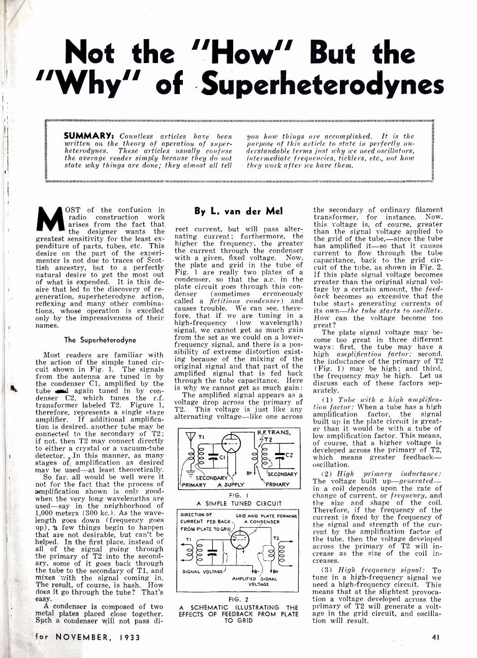
Not the "How" But the "Why" of Superheterodynes
llUllilllllllllllllllllllllllllllllllllllllllllllllllllllll mono llllll 'mum 'mum lilllllllllllllllllllmllllllllllllllllll 'min 111llll vim llllllllllllllllllllllllllllllllllll11 'mum Illilllllllllllll illlllllilllllllllllllllllllllilllllll min' 'mum lilll iii minimum mum llllllL'
SUMMARY: Countless articles have been written on the theory of operation of super - heterodynes. These articles usually confuse the average reader simply because they do not state why things are done; they almost all tell
i; IIuIIl llllllllllllllllllllllllllllllilllllll llllllllllllllllllllllllllllllllillllllllllllllllllll IIIIII1111111 i111111111111Illllllllllllll11111IIIIIIIIIIIl111111111111IIIIIIIIIIII IIIIII1l llllllll lllllllll ll ll111ll1111111111lli lllllll11111111111IIIIIII IIIIIIII1111111II11IIIIIIIIIIII IIilllllllllllllllllllllllllllillllli
you how things are accomplished. It is the purpose of this article to state in perfectly un- derstandable terms just why we need oscillators, intermediate frequencies, ticklers, etc., not how they work after we have them.
OST of the confusion in radio construction work arises from the fact that the designer wants the
greatest sensitivity for the least ex- penditure of parts, tubes, etc. This desire on the part of the experi- menter is not due to traces of Scot- tish ancestry, but to a perfectly natural desire to get the most out of what is expended. It is this de- sire that led to the discovery of re- generation, superheterodyne action, reflexing and many other combina- tions, whose operation is excelled only by the impressiveness of their names.
The Superheterodyne
Most readers are familiar with the action of the simple tuned cir- cuit shown in Fig. 1. The signals from the antenna are tuned in by the condenser Cl, amplified by the tube awl again tuned in by con- denser C2, which tunes the r.f. transformer labeled T2. Figure 1, therefore, represents a single stage amplifier. If additional amplifica- tion is desired. another tube may be connected to the secondary of T2; if not, then T2 may connect directly to either a crystal or a vacuum -tube detector. In this manner, as many stages off. amplification as desired may be used -at least theoretically.
So far. all would be well were it not for the fact that the process of amplification shown is only good - when the very long wavelengths are used -say in the neighborhood of 1,000 meters (300 kc.) . As the wave- length goes down (frequency goes up), 'a few things begin to happen that are not desirable, but can't be helped. In the first place, instead of all of the signal going through the primary of T2 into the second- ary, some of it goes back through the tube to the secondary of T1, and mixes with the signal coming in. The result, of course, is hash. How does it go through the tube? That's easy.
A condenser is composed of two metal plates placed close together. Such a condenser will not pass di-
By L. van der Mel
rect current, but will pass alter- nating current ; furthermore, the higher the frequency, the greater the current through the condenser with a given, fixed voltage. Now, the plate and grid in the tube of Fig. 1 are really two plates of a condenser, so that the a.c. in the plate circuit goes through this con- denser (sometimes erroneously called a fictitious condenser) and causes trouble. We can see, there- fore, that if we are tuning in a high -frequency (low wavelength) signal, we cannot get as much gain from the set as we could on a lower - frequency signal, and there is a pos- sibility of extreme distortion exist- ing because of the mixing of the original signal and that part of the amplified signal that is fed back through the tube capacitance. Here is why we cannot get as much gain :
The amplified signal appears as a voltage drop across the primary of T2. This voltage is just like any alternating voltage -like one across
SECONDARY RIMARY A SUPPLY
B+
R.F. TRA NS. Li T2
C2
SECONDARY
PRIMARY
F! G. I
A SIMPLE TUNED CIRCUIT
DIRECTION OF
CURRENT FED BACK
FROM PLATE TO GRID
TI
GRID AND PLATE FORMING A CONDENSER
T2
SIGNAL VOLTAGE) B- 84
AMPLIFIED SIGNAL VOLTAGE
FIG. 2
A SCHEMATIC ILLUSTRATING THE EFFECTS OF FEEDBACK FROM PLATE
TO GRID
the secondary of ordinary filament transformer, for instance. Now, this voltage is, of course, greater than the signal voltage applied to the grid of the tube, -since the tube has amplified it -so that it causes current to flow through the tube capacitance, back to the grid cir- cuit of the tube, as shown in Fig. 2. If this plate signal voltage becomes greater than the original signal vol- tage by a certain amount, the feed- back becomes so excessive that the tube starts generating currents of its own -the tube starts to oscillate. How can the voltage become too great?
The plate signal voltage may be- come too great in three different ways : first, the tube may have a high amplification factor; second, the inductance of the primary of T2 (Fig. 1) may be high; and third, the frequency may be high. Let us discuss each of these factors sep- arately.
(1) Tube with a high amplifica- tion factor: When a tube has a high amplification factor, the signal built up in the plate circuit is great- er than it would be with a tube of low amplification factor. This means, of course, that a higher voltage is developed across the primary of T2, which means greater feedback - oscillation.
(2) High primary inductance: The voltage built up- generated -- in a coil depends upon the rate of change of current, or frequency, and the size and shape of the coil. Therefore, if the frequency of the current is fixed by the frequency of the signal and strength of the cur- rent by the amplification factor of the tube, then the voltage developed across the primary of T2 will in- crease as the size of the coil in- creases.
(3) High frequency signal: To tune in a high- frequency signal we need a high- frequency circuit. This means that at the slightest provoca- tion a voltage developed across the primary of T2 will generate a volt- age in the grid circuit, and oscilla- tion will result.
for NOVEMBER, 1933 41

le Intermediate -Frequency Amplifier
Of course, a :low- amplification factor tube could be used in, order to limit the gene' jed .u.late circuit voltage. Such a, S ore, however, means low fir'
' a should not be
considered` -by any one who wants the most -'f1 mìi his set. We could reduce thcr size of the primary of T2, and reduce the voltage that way: but here again, a small primary means a small voltage, and a small voltage means small gain. This system should not be used. The only remaining method, therefore, is to reduce the frequency to a value that Nyill enable high gain with no oscil- lation. This is exactly what the su- perheterodyne does.
Up to this point it is clear that the best way to obtain high gain is to reduce the frequency of the signal to be heard to a low value. and amplify it at this new, low value. The amplifier that amplifies the low - frequency signal is called an inter - mediate- frequency amplifier. It is so named because it is placed be- tween the antenna. or high-fre- quency stage, and the detector, or low-frequency stage.
The Need for an Oscillator
Now that we have our inter- mediate- frequency ( abbreviated i.f. amplifier, the next problem is that of reducing the signal to a It v value. This feat is neatly accomplished by the oscillator. It might seem para- doxical at first to deliberately take pains to eliminate oscillation, and then just as deliberately insert an- other oscillator in the circuit. It's not paradoxical. it's radio' The re- duction of frequency has been cov- ered in so many "hu\V" articles that it will not be repeated here this is a "why" article. \Ve are concerned here with the fact that an oscillator is necessary to reduce the frequency of the incoming signal in order that it may he amplified effectively by the i.f. amplifier. The status of Our receiver to date is block -diagrammed in Fig. 3.
One important point in connec- tion with the oscillator- antenna cir- cuit has not been emphasized enough in previous superhet articles. The point is that when the oscillator output mixes with the signal, the result is not a (inference in fre- quency between the two -the ditíer- el'ce in frequency is only obtained after the mixture is rectified, or de- tected. Hence the necessity for lI
first detector. Let us analyze this condition a little more.
The signal direct from a broad -
casting station is a mixture of the steady carrier with the music or voice superimposed. If we want to hear the music, it is necessary to detect the wave with the ordinary crystal or vacuum -tube detector. The net result of this detection is to pull out the audio part -which we want to hear -from the entire mixture. Now, the grid of the first detector
ANT L ,NA CIRCUII
TO SECOND DETECTOR
FIG. 3 -BLOCK DIAGRAM OF A SUPER This diagram illustrates points of con-
nection of the parts of the super.
tube in a super hag both the oscil- lator and the signal voltages im- pressed upon it. In order to get the i.f. from the combination, it is ab- solutely necessary to detect the com- bination with a first detector, ex- actly as in any ordinary tuned- radio- frequency receiver. There is no difference frequency measurable un- less detection takes place. This point is illustrated in Fig 4.
The frequency of the oscillator is important simply because it deter- mines the difference, or i.f.. fre- quency. This difference frequency may be obtained in either of two ways: first, by having the frequency of the oscillator greater than the signal frequency by an amount equal to the i.f.: or second, by having the frequency of the oscillator lower than the signal frequency by an amount equal to the i.f. Either method works as well as the other, although the higher -frequency set- ting of the oscillator is almost uni- versally used. The reason for this involves a rather complicated discus- sion of harmonics, image frequen- cies. etc., and will not be discussed here.
Our super now consists of an antenna circuit. an oscillator circuit and an i.f. amplifier which connects to a second detector in order to re- move the audio which we want to hear. Of course, it is possible to install an r.f. amplifier ahead of the first detector in order to get amplifi- cation at r.f., before it is mixed with the oscillator. In this case, then. we will have one tuning condenser for the r.f. stage, one for the first detector, and another for the os- cillator. The i.f. amplifier does not hi ve any variable tuning condensers
OUTPUT JUSTA " XTURE- MO DIFFERENCE FREQUENCY
ANT. SIGNAL 11,000 K.G.
OSCILLATOR 11,456 K.C.
DIFFERENCE FREQUENCY /
4OG K.C. TO
I.F. AMPLIFIER
FIG. 4- ANOTHER BLOCK DIAGRAM This diagram illustrates just where the
difference frequency is obtained.
for the simple reason that it works at a fixed frequency, and when once adjusted, stays constant. This rep- resents one of the most distinctive advantages of the superheterodyne: it is possible to get many more stages of amplification before actual audio detection than in a tuned r.f. amplifier, not only on account of the lower frequency involved, but be- cause of the obvious fact that no tuning condensers are required in the i.f. amplifier. In a receiver of the tuned r.f. type, a tuning con- denser is needed for each stage. In a four -stage amplifier, four tuning condensers are necessary. In a super with the same number of tubes, only two tuning condensers are needed: one for the first detector and one for the oscillator. Thus, the super would have two stages of i.f. A block dia- gram of a complete superheterodyne using one stage of r.f., up to and including the second detector, is shown in Fig. b. The function of each separate unit is shown on the diagram.
In the next installment, a descrip- tion of the "why" of regeneration will be given.
While it is emphasized in this ar- ticle that oscillation must be elim- inated before successful operation of a superheterodyne can be obtained, it might be well to point out that, paradoxically, certain forms of oscil- lation are absolutely essential to the successful operation of regenerative receivers.
It might be well to further qualify the above statement by showing that unintentional, or parasitic, oscilla- tions are undesirable; but oscilla- tions that can he readily controlled are essential.
COMBINES SIGNAL AND OSCILLATOR To PRODUCE I. F.
DETECTOR
tM1YER1
o
I R,F,
STAGE
It! o
I. AMPLIFIER SECOND DETECTOR
AMPLIFIER
AMPLIFIES RF.
USED TO
PRODuCE I.F.
AMPLIFIES SIGNAL AT LOW FREQUENCY
CALLED I.F.
PRODUCES AUDIO
i
TO AUDIO
o
OSCILLATOR
FIG. 5 -BLOCK DIAGRAM OF A COMPLETE SUPERHETERODYNE RECEIVER The purpose of this diagram is to illustrate the function of each of the units used in
a superheterodyne.
42 SHORT WAVE RADIO

The Maligned Modulator (Continued from rage 20)
Modulator Couplings Calmly assuming that the audio
amplifier is O.K., we arrive at the final audio tube, which is normally called the modulator. The output of this audio stage is fed into the r.f. system for the purpose of modulat- ing the r.f. carrier, and far too often this is done via a coupling device that is O. K. -in part. A common oversight is to use separate filament supplies for the final audio tube (modulator) and the modulated r.f. tube (modulatee ?) without provid- ing a low- impedance audio path be- tween these two filament sources. Bypasses will patch this up if they have a capacity of 4 or G "mikes" each, but the really correct cure is one filament supply of ample size.
Again, where a Class A amplifier is coupled to an r.f. plate circuit through a resistance- capacity combi- nation, one commonly finds the resis- tance bypassed with as little as 1
mf. -which quite effectively spoils low -note modulation. The plate sup- ply for such a modulator system is usually through an iron -cored choke, and in numerous cases this has been found to have either insufficient in- ductance to operate well at low notes or to have such high distributed ca- pacity as to let high notes escape. If one must use cheap chokes, at least use them with 2 or 3 times the cur- rent rating that appears to be neces- sary, and put several in series.
Class B amplifier stages (used as modulators) occasionally produce a curious effect: good audio at me- dium levels, fair audio at low levels, and terrible audio at high levels. In these cases one had better suspect two things at once -r.f. is sneaking into the audio system and damaging the low -level performance, or plate - supply surges are disturbing a buffer stage at high levels. In curing the first, consider the audio system as if it were a broadcast receiver in a broadcast station, and shield and fil- ter as this suggests. As to the plate- supply surges, check up by tempo- rarily using separate buffer plate supplies, or else what is nearly equivalent -feed the buffers through ant added filter of about 100 H. -real henries -and 4 mikes.
Reciprocity Since the audio system is falsely
accused for every crime of the sta- 4bs °.°b,
s+' I 'et,-
I
Pv - ,I_- - -- e;o fEEOBACie
ti
Naga al ' I (Unmodanted) a,
e to //s & Amps.
1;.ïó 1
k°ly 1
TANK AMPS
THE STRAIGHTER THE BETTER
ZX NORMAL varnoc - _ R.F FROM
BUFFER /f/ADEQUATE o'
0
for NOVEMBER, I933
win the Denton rophy
with an rakiyre, ACRATONE TWO TUBE
K ITS
Models 15A. IOA, and 45A
THE ARGONAUT KIT
Model 15A 1 -ses L' type 230 tubes. The tira as a regenerative detector and the second as an audio tube. This re- ceiver only requires two 1>/ volt dry cells and a single 45 volt "B" battery. Kit less coils and tubes $5.65 Set of batteries for above 1.28 Set of four coils. 15 to 201) meters 1.29 2 Raytheon 4 Pillar tubes. 230 1.37
THE AIR ROVER KIT
Model IOA Similar to above but especially sensitive. Uses 1 -232 and 1 -233 tubes. Kit less coils and tulles $5.95 Set of four coils, 15 to 200 meters 1.29 Set of batteries, 2.16 Set of Raytheon 4 pillar tubes I1 -2232, 1- 233) 2.12
THE VOYAGER KIT
Model 45A Similar to above but A.C. operated. Uses 1 -57 de- tector and 1 -59 power pentode. Kit less coils and tubes $5.95 Set of four coils, 15 to 200 meters 1.29 A.C. Power supply Cat. N. 739 (less 230 tube) 4.95 Set of ItaStheon 4 pillar tubes (1 -57, 1 -JS, 1 -2S0) 2.52
NOTE: Add $3.00 for any of the above receivers if desired wired and tested.
THE ACRATONE DISCOVERER KIT
A Real Distance Getter A 5 -tube A.C. operated short wave receiver
The Discoverer is a 5 -tube T.R.F receiver having one stage of 1'.R. F. using a 58 tube, two stages of audio, the first using a 56 tube and the second a 59 power output pentode and a rectifier stage using a 280 tube. The receiver is equipped with a self- contained power supply for 110 to 125 volts A.C. 50 to 60 cycles. A phone jack is provided for those who prefer phones. Provisions are made for the noiseless doublet type antenna. A set of eight space wound coils are used, four for the R. F. stage and four for the de- tector. These coils cover from 15 to 200 meters.
The Discoverer Kit Complete with (7abinet, Parts, Full- Vision Dial, set of 8 coils (5 to 200 Q meters), Power Supply and In- structions
.95
81/2" Dynamic Speaker -Specially a 80 Matched -Cord & Plug -Cat. No. 41 728
Set of 5 Raytheon Four - Pillar .75 Tubes (2- 58's, 1- 56, 1- 59, P 1- 80)
BUILD THE DENTON TRIPLEX
COMPLETE KIT INCLUDES: I Set of 4 Special Plug -in Short \ \'ave Coils
covering bands from 10 to 200 meters, type No. 7S14 $1.85
I \crates) 7'riple Binding Post. No. 4106 .12 1 Acratest Twin Phone Tip .lack, X. 4169 .06 1 Four Prong Wafer Socket, No. 4062 .05 1 Six Prong Wafer Socket, No. 6934 .06 1 Seven Prong Wafer Sorbet, No. 7524 .06 2 4eraItst R.F. Chokes No. 6755 .20 1 Aerate,t 'Midget Variable Condenser .000025
mfd, Nn, .45 1 Acratest \'nriab5256 le Condenser, .00015
mfd. No 6834 .95 1 Fotii (' b lino a Battery Cable, No. 7134 .15 1 Acratest Shielded 'fetal Chassis & Front
l'auel, No. 7450 1.50. I Acratest Dial & Drive Unit, No. 7779 .25 I Acratest Escutcheon Plato, No. 4043 .I5 1 Acratest Screen Grid Clip. No. 4173 .02 3 Black Knobs, No. 't ) .30
1 Acratest New -type Tube Shield, No. 7173 1 Frost 50,000 ohm Potentiometer, No. 6156 1 Fleohtheim G.F. 100 By -pass Condenser No.
5275 1 Acratest .1 mfd., 200 volt Tubular Condenser,
No. 5637 2 Acratest 0001 mfd. Mica Condensers, type
No. 6637 1 Acratest .0001 mfd. Mica Condenser, No, 6630 1 Acratest .00025 mfd. Mica Condenser, No.
6632 1 Acratest 350 ohm, ' watt Resistor, No. 5560 .08 1 Acratest 3 megohm, % watt Resistor, No.
5860
.20
.45
.43
.08
.14
.08
.10
.08
TOTAL-57.81 Net Price of Alloue Parts If Purchased in one Kit
$6.95 1 Raytheon 6 F 7 Tube $1.32
All our branches carry a complete line of short wave sets and parts, replacement parts, broadcast receivers, tubes, public address equipment, meters and other radio supplies. Send for our complete 108 -page FREE catalog.
25 Park Place, New York, N. Y.
ATLANTA Ga. 631 Spring St.
N. W. 2909 N. 92.26 Merrick 534 E.Fordham 273 Central 343 Blvd. of 1331 S. Michi
I
Philadelphia, Pa. IJamaica,L.I.,N.Y.I BRONX, N. Y. INEWARK, N. J. Pittsburgh, Pa. (CHICAGO, ILL.
Broad St. Road Rd. Ave, the Allies gan Av.
43

Complete Kit of Parts Prue
CONVERTIBLE 5
NOW PERFECTED LOUD SPEAKER RECEPTION FROM FOREIGN STATIONS London, Paris, Rome, Madrid, Sydney, Buenos Aires- the world at your finger tips with the new short wave "Convertible 5". Clear, undistorted reception from your loud speaker, with sufficient volume to compare with local broadcasts. Covers all short wave channels between 13 and 200 meters. You radio fans will enjoy constructing this new, modern kit. Simple, easy wiring and construction. Tested circuit employs the newest 1933 pentode tubes, full A.C. opera- tion, freedom from body detuning effects, and dynamic loud speaker reception from European, Asiatic and Australian stations. Send 35c far easy to follow wiring diagram and complete list of individual parts and price. We carry all parts for the Convertible "S ".
Here is the latest. greatest catalog ever is sued by WHOLESALE RADIO SERVICE CO. More than 10,000 Bargains are listed! Every latest development of the foremost manu- facturers is here! SETS. TUBES. SPEAKERS. REPLACEMENT PARTS. KITS. etc. -all at LOWEST WHOLESALE PRICES!
SHORT WAVE APPARATUS A most complete selection of short wave sets. converters. coils and equipment is displayed here. Nationally known makes such as NATIONAL.HAMMARLUND and LAFAYETTE featured prominently.
PUBLIC ADDRESS comes in for a big share of attention in this catalog. Amplifiers, Amplifier Kits. Complete Systems, Portable Systems and all kinds of equipment are listed at prices which are truly amazing.
SPECIAL FEATURES covering Lafayette Receivers, Trutest Parts, Miniature A.C. -D.C. Portable Sets, Testing Equipment are a few of the special features in this most complete Radio Catalog of the en- tire industry! BUY FROM WHOLESALE RADIO SERVICE CO. at lowest wholesale prices -where your satisfaction is guaranteed and where the promise of prompt service is p r to -me 1!
jOSALE RADIO SEE pl CORNER GRAND ST. (ma swot asovr cwMwiINEUI YORK.N.1/.
enclose 35c for wiring diagram and price list of individual parts. ( ) Please Rush your Brand New Catalog.
Name
Address
City .State
44
tion and the ether, it is fair to turn about and demand that the r.f. sys- tem prove its innocence. This means that the r.f. system must show abil- ity to accept modulation and to re- produce it. This isn't as complex as it sounds -though unfortunately there has been widely published a curious and confusing definition of Class C (tube to be modulated) oper- ation. This tube almost always op- erated with a plate tank -circuit which is tuned. An r.f. meter can' be con- nected across a turn or two of this tuned coil and proper operation has been obtained when the current shown by that meter varies in pro- portion to the plate voltage. If the normal plate voltage is 250 and the normal tank -meter reading 2.5 am- peres, then the meter should read 1.1 amperes at 110 volts and 5 am- peres at 500 volts. Try it point by point and see.
If the meter readings do not go up and down in direct proportion to the plate voltage -even the most moral modulator will never get perfect speech out of the critter. Sometimes the proportionality is O.K. at points below the normal voltage, but not above- meaning that we can modu- late down O.K., but not up without distortion. Any one of a lot of things may be wrong. The final fil- ter condenser must be at least 4 mikes -6 is better -8 for a Class B system. The r.f. feed to the grid of the modulated r.f. tube may be wrong -generally too much. The neutralization may be wrong. The bias of the moduated tube may be incorrect or variable- better get it partly from a grid leak and avoid grief.
Oh, any one of a whole lot of things may be wrong; and mostly they can be located right at the transmitter, and mostly they are anywhere except in the modulator.
And that's our story -and we give you fair leave to go back to your ap- paratus with new confidence and self- esteem. And if any self -ap- pointed long- distance listening wiz- ard starts to edit and revise your modulator -just ask him to go back to his musty old Middle Ages where they used to believe in him.
4PID 4P75
, / FREQUENCY RESPONSE
RESPONSE VS. PRICE
The quality of a microphone is almost a direct function of its price.
i
'11 111111111111111111111111111111111111 I I I I I I I I11011111 p 1I I11111! 11 1111111111I
I I I I I I I I I I I I I I I I I I I I I I I I I I I 111111111111111111 1 1 p I I
SHORT WAVE EXCHANGE
Have you some apparatus to sell or swap, or some special service to offer to other short-wave fans? Take advantage of the low rates of this department to reach other "hams ". Only 5 cents per word for amateurs, B cents per word for manu- facturers or dealers. Name, initial and address each count as one word. Not less than 10 words accepted. Cash, money order or U. S. postage stamps rust accompany all advertisements. Please write clearly.
1111111111111111111111111111111111111111111111111111111111111111111111111111111111111111111111111111111111111111111111NI1111,
SHORT WAVE RECEIVERS at bar- gain prices. Write W. A. Kiesow, Morgan, Minn.
PLUG IN COILS. Set of four wound on bakelite. Four -prong forms. 15 -210 meters. $.50. Noel, 809 Alder, Scranton, Pa.
HAM SUPPLIES bought sold. En- nis, Route One, Johnstown, Pa., W8GPA.
QSL CARDS, NEAT ATTRACTIVE, Reasonably priced, samples free. Miller, Printer, Ambler, Pa.
THE ANSWER FACTORY has un- snarled many puzzles of amateur and commercial operators. Prompt quotations, reasonable prices. Robert S. Kruse, RFD No. 2, Guilford, Con- necticut.
BRUNO condenser mike kit, brand new, $1.00. 20 power brass draw telescope, spots .22 holes at 200 yards, used but good condition. $1.50. Special Jensen 8" permanent magnet dynamic, for P.P. 38's, no baffle, new, $3.00 A. Bachner, 3970 -48th Street, Long Island City, N. Y.
:11111111111111111111111111111111111111111111111111111111111111111111111111111111111111111111111111111111'
Question and Answer Service BEGINNING with the next
number, there will be a reg- ular monthly question and an- swer department in SHORT WAVE RADIO. Matters of general in- terest to short -wave fans will be discussed in this section in brief, understandable language.
Readers desiring personal re- plies to their questions are re- quested to observe the following simple rules: (1) If your ques- tion is of a straight technical nature and does not involve the preparation of diagrams by us, merely enclose a stamped and addressed envelope; there is no charge for the service. (2) If you want diagrams of sets using not more than five tubes, please enclose twenty -five cents (U. S. stamps are acceptable); for lar- ger diagrams, fifty cents. We are forced to charge these mod- est fees because the drawing of diagrams to fit individual collec- tions of parts and equipment takes considerable time, and often entails actual engineering design effort.
11111111111111I11111111111111111111111111111111111111111111111111111111111111111111i111111111111I11111111 r
SHORT WAVE RADIO
ED O f RADIO
45VeseyStreet, NewYork City NewYork Headquarters for Transmitting Apparatus
The Radio Amateur has found it con- venient to shop at LEEDS. Only quality merchandise at wholesale prices.
We have a complete line of the following:
National General Radio Ilammarlund Weston Jewell Cardwell Flechtheitn Morrill Universal
and many others We do not publish a catalog; quota- tions on all short wave equipment furnished by return mail.
UNIVERSAL MICROPHONES and stands at lowest prices
Model {l' lapel single button $1.'ï5 5
Model X double button... 5.88 Model X single button 4.41
Model BB 14.70
Model X desk stand 2.05 Special floor stand nickel plated.. 5.88 Suspension springs, S for .25
All other Universal products reduced to above proportions
Navy Type Telegraph Key List $3.60 Navy knob-1/4" tungsten
contacts. Special $1.25 with regular knob 1.10
T1íe.a\u£.S74A1
interesting amateur
"KEY KLIX" IS OUT!
Thousands of amateur radio items at the lowest
prices, are contained in this
immense 192 -page FREE
book, together with many
articles by people well known in
radio circles.
Get your copy NOW
AMERICAN SALES COMPANY Wholesale Radio Distributors
44 W. 18th Street, - New York, N. Y.
The Oldest 'HAM" Supply House Established 1919
Subscribe? Sure! Why not now? No reason at all.
Then turn to page 48 for a real,
man -sized coupon and an invitation
to read the greatest short -wave mag-
azine ever printed. the transmitting and Leur is to be found. know!
Everything for
receiving ama-
Don't guess-
for NOVEMBER, 1933
5 -Meter Receiver (Continued from page 40)
potential, it is necessary to insulate it from the metal chassis. This is another reason why the coupling be- tween the condenser and extension shafts must be of the insulating type. If these shafts were connected metallically together, then the rotor of the condenser would be placed at nearly ground potential because of hand capacity when tuning, and the stability of the receiver would be thrown off considerably. Underneath the chassis, condensers C5 and C4, resistor R1, transformers T1 and T2, the off -on switch and the phone jack are placed in position and wired as per either the pictorial or schematic diagram.
Constructing the Coils
Coils Li and L2 are seen to be mounted in mid -air, close to the tun- ing condenser. Each consists of 33/i turns of No. 14 solid enamel wire, wound on a 1/2 -inch dowel stick. The spacing between turns is equal to the diameter of the wire. The spacing between L1 and L2 is approximately 3/s inch. It might be well to try varying the spacing and the number of turns on each coil slightly in order to secure best results. The ends of the coils act as the support for the coils. With the midget tuning con- denser and L1 and L2 as specified, the beginning of the 5 -meter band
L2 R.F. CHOKE
TICKLER V1
L3
C5 TO
V3
TZ
V2
-
13+
Circuit showing the series connection of the detector and quenching tubes, plate circuit.
should come out at about 10 on the dial.
Although the quenching coils L3 and L4 used in the receiver are com- mercial, they may be wound at home as follows : L4, 1,400 turns of No. 34 silk -covered wire, wound on a 3/8"
dowel between cardboard discs spaced 1/4 inch apart. L3 consists of 900 turns wound with the same size wire in exactly the same manner as L4. The choke r.f.c. may also be made by winding about 40 turns of No. 26 silk- covered wire on a Bake- lite rod 1/4" in diameter. The wind- ing length of this choke is approxi- mately 1136".
(Continued on following page)
Every RADIO WORKER Should Have the HA IIIIARI.I- N D
CATALOG QUALITY of radio parts is
the first essential of satis- factory performance.
That is why Hannnarlund's more - than- thirty years of engineering experience means so much to radio builders who prefer rc'r- formancc to promises. The new Hannnarlund Catalog "33" describes condensers, Coil forms, sockets. transformers. chokes, couplings. equalizers and shields for all types of radio work -transmitting or standard and low -wave reception. 1 /nil coupon for your free copy.
ISOL:I:ATITE tiO IEI'ti und (:OIL FORMS
Sockets have Isolantite hase and perfect spring contact-. for 4, 5 and 6 prone. Isolantite Coil Form, for Short and 'Un- :: Short Waves. No drill - ing. 4, 5 and 6 prongs.
Improred MIDGET CONDENSERS
Ideal for short -wave and ultra short- wave tuning. Sturdy frame. Sol- dered brass plates. Smooth hearings. Four -point wiping rotor contact. Isolantite insu- lation. Not affected by tem- perature or hu- midity. Vibra- tion- proof. Eleven stock sizes, 3 mmf. to 320 mmf. ca- pacity.
3r1t.SC,T.tOY tar.diry
ammarlund PRECISION
PRODUCTS
HAMMARLUND MANUFACTURING CO. 424-438 W. 33rd St., Nov York. N. Y.
Check here for General Catalog "33." l'In -elc bete for folder on "Air- Tuned" I. 1' '11anat.th,,, ] ('heck here for booklet describing CIIMJ'T "I'lto" short - \\ln Superheterodyne.
Name
Address
sll-io
45

LYNCH Short Wave Antenna System
will help you win the Clifford E. Denton Trophy
American Sales Co. 44 tCrc>t !ttit Street, NC,, Vi,ri. Clty
Jul 'uth Ivt: \lanu,l.rctgrihK Iulcr,.y
[Al 1t tro. t. or I. \ Y. Au N\Ir .Ar,hur
r
ah I., Li,.I,IL.wo.u. tl,r c ,.r,l..:at,l pl,ui,g and pole .itti1,. w
: I , _ : : . .n,
: L.. Hat top A. -ion 1
doublet Hat top i- 1 a, -I at,.uut r,lnl It ale, the 11c hen asal riot-tot-ilk., l,hks rind
t raf-I -.I th, .1. ;III iL.- en a
v do,.,, p, the H,,,, lip 1. ,he ntefa
nl, ,.`III. I. .,.,r. thefts-I,,s in the -bow room
lu the past, it has 1 -en impossible to receive many s l a t wl,; ill, - 1 , 1,ns I,ruwi act reod, ,'. distribute due 14, he ser) Idyl, noise IeceI r, by machinery fl,r _huu.,,,t the ueiehborlmod 1, wag also praetIra ll> io,p,a -i!le tar os to ,Ieuwn- Sirate short wave re. ei,, until we installed soup doublet ar,teulia with teas- p.,..e,l trarmmis-iou lire- Without any etagg,rat ion whatauever, we toilful the noise level to drop F43' or more after the in- stallation was made Ke are tot,. able to tune broadcast dial bars on both the broadcast and i l',r wave [rands with praeti,-ally I wioe at any tithe.
Yours very milt'. A31EK1('AN SALES COMPANY
(Signed, t.. .Arno ct
Complete Kit Sí.00 At ALL LYNCH Jobbers and Dealers
If your Jobber. Dealer or Serviceman cannot supply you, order direct from us. Sent post- paid, with instruction booklet, for $5.00.
Free Descriptive Folder Upon Request LYNCH MANUFACTURING CO., Inc.
51 Vesey Street, New York, N. Y. Makers et the Famous Metallized Resistors
M A We have complete stock of masts up to
100 feet made horn clear, light spruce. We ship knockdown, with all holes drilled and with bolts, hardware and
S instructions.
We also carry complete line of parts for transmitting amateurs and we also manu- facture complete line of radio equipment. T We specialize in short wave receivers for 5 and 10 meter bands. Try our new Pentagrid Short Wave Four Tube Superhet at $44.
S You who live in Maine will do well to use our store as your base of supplies, as we carry only the best grades of apparatus.
COMMUNICATION
VERTICAL ANTENNAS
are best for DX recep tion or transmission
LABORATORI ES
North New Portland- Maine
It should also be noted that the tubes used are all type 30's, and re- quire two volts on their filaments. In all probability they will be used with two dry cells connected in series, giving a total of 3 volts. If so de- sired, a 15 -ohm rheostat may be con- nected as shown at R2. If a fixed unit is desired, then R2 may be made about 5 or G ohms, which will main- tain the filament potential at approx- imately 2 volts.
As stated at the beginning of this article, this receiver does not repre- sent the ultimate in ultra- high -fre- quency receivers. Its main purpose is to acquaint the reader with 5- meter operation which, when devel- oped a little more, promises to be one
of the most fruitful fields for the experimenter.
Concluding Notes Under normal conditions of opera-
tion, the super -regenerative receiver will give a loud rushing noise; but when tuned to a signal, this noise will disappear entirely and the sta- tion will come through clear and dis- tinct. Antenna condenser Cl is ad- justed to suit individual antenna sys- tems and its correct position may easily be found by adjusting it until signal strength is at maximum. The fixed resistor R1 is merely used to placed the grid of VI at ground po- tential which stabilizes the grid cir- cuit.
Capt. Hall Identifies Foreign Stations (Continued from page 12)
crated station located in Nassau, Bahama Islands.
1íV59, Moscow, Russia, on 50.00 meters, is being heard again. Their scheduled time on the air is 2:00 to 5:00 p.m. E. S. T. The best recep- tion is around 4:00 p.m. Eastern Standard Time. The technician of KGU, Honolulu, informs us there are no short -wave broadcasting sta- tions in Hawaii. A commercial sta- tion used f'or telephony does occa- sionally transmit musical programs.
CT : AQ, Madeira, which operated on 2G.8:'' meters has left the air ac- cording to information received.
An English correspondent informs us that there is a station in Russye- lede, Belgium, reported on 29.5 meters.
Mr. Bass reports yV3BC, Caracas, Venezuela, on 48,95 meters, broad- casting until 12 p.m. Daylight Sav- ing Time.
Pulling in stations is not such an arduous job, but "pulling verifica- tions of reception away from some of those foreign stations -that is NVhere the work comes in.
Many fans have written us and asked what would be considered a diplomatic way for a beginner to go about this thing in the proper way. Here are a few hints, not only for the beginner, but also for the grey-
The "EAGLE a new sensational 3 tube S.W. Receiver The only popular priced set having the
band spreading feature
GROSS RADIO, Inc.,
$11.95 CHECK THESE FEATURES I f
SCREEN GRID end J. teeter uttering highest pu -il.l, nid no, PENTODE POWER AUDIO -.I [rive, more audio gain than obtnim.I
tattled stare. Will operate speaker on
TANK CONDENSER t. [.-r -u,-,t from the front of u cal and entraits. s.ity of lifting the roNt.r. Speedy range changes at
I AUUlI'II PNA I. condo employed here gives condenser H ft e with the ordinary large condenser.
BAND SPREADING CONDENSER-very rmall capacity permits widest dd ,I , ..1 urtdtituáe of rouges l hi, feature give.
. t,..,11, t, ,, ,,., ii, r. tun tt- [rira of one. DIAL -Lu tort de,,ru recul vernier control over any positir,n of the frerruat.a-
n-d. %tat, Iy will not lump or slip -very rugged. REGENERATION CONTROL -Employs oondeneer for stability, rugged-
,. - , noutlmesa. out noisy like resistances. POWER CABLE -LOni note. possibility of wrong connections and insure-
absolute I r , :d contact. CABINET - . 7 x Ott", metal, compact, hinged cover. cry,talliu-J
I ,,ly shields the receiver. Alai, ideal for porthole use. RANGE - 600 meters -4 plug -in coils are supplied with each receiver. EAGLE" completely wired and tested. Price $11.95 TUBES - I tubes 53.00
I - operate. Employa the new 2 volt tubes which Cao operated t r..,,, n,,, dru r,-tle un the filaments for extended periods of time.
Shortwave Headquarters S1 Vesey St.. Dept. R. New York CItY Tel. Barclay 7 -0161
46
beard, who has become weary wait- ing an answer from a foreign sta- tion. But let me say right here that the foreign stations are not the only broadcasting stations that ignore letters addressed to them. I have written W1'BXK, Pittsburgh, Pa., sev- eral times, and am still waiting for an answer and they are only several hours away from our own back -door. So there!
Let us take this important item step by step. First, the tuner hears a program and writes down every- thing he hears. If several different musical selections are played, one right after the other, he should, if he i5 a wise tuner, make a note of this. Some stations have identify- ing signals, and the ones that have none generally give their call letters. Some stations announce at regular intervals, while others announce at the beginning and close of their broadcast. The language used will give the average tuner a very good idea of what station he is listening to.
When requesting verifications, describe the program briefly -not at length. Well, more next month.
The Denton Trophy (Coot /no( Jrent page 32)
N. Y., U. S. A., accompanied by a self -addressed stamped envelope or container, together with sufficient postage or international reply cou- pons to cover return by registered mail. Judges will not be responsible for any loss of verifications. All let- ters and cards of verifications, to- gether with envelopes or other wrap- pers, should be presented. Stamps should not be removed or post -cards defaced. The judges will do every- thing possible to see that all verifi- cations are properly returned to the contestants.
All prizes will be awarded with the stipulation that they may be dis- played for one month after the award is made in any appropriate place or places that the judges may select.
SHORT WAVE RADIO
No code stations, amateur, air- craft, police, ship or commercial sta- tions will be considered in the con- test, unless the verification actually states that the program received by the contestant was of broadcast na- ture. Only one verification from each short -wave broadcast station will be allowed.
In cases such as English, Swiss or German stations, where the same station uses more than one trans- mitter, wavelength or set of call let- ters, the verification must state the individual wavelength and call letter of the transmitter from which the program was received.
In writing to the various short- wave stations for verifications, it is suggested that the listeners -in men- tion the fact that such verifications are to be used in the Denton Trophy Contest. The cooperation of vari- ous stations is being arranged for by the trophy committee.
While it is not absolutely essential, it will simplify the work of the Den- ton Trophy Committee if prospec- tive contestants will signify their in- tention of competing in this contest by advising the Denton Trophy Com- mittee, 23 Park Place, New York City, N. Y., attention Clifford E. Denton.
SHORT WAVE RADIO heartily en- dorses this contest, and suggests that as many of its readers as pos- sible enter it. It promises to be a lot of fun.
The Triflex (Continued from page 9)
culty that may be experienced is with the three holes for the coil, and tube, and the cable connector. With a little care and patience, these holes may be drilled by means of a series of small holes drilled around the circumference of the holes desired.
Now, mount the antenna -ground binding post strip ; the phone ter- minals ; the 5 -plate midget conden- ser, Cl ; the regeneration control, R1; the tube, coil, and battery sock- ets ; the 1 mf. bypass condenser ; the a.f. transformer ; and the tuning con- denser, CG. In wiring the receiver, it is best to wire the filament cir- cuit first, then the grid circuits, and, finally, the plate circuits, leaving the incidental resistors and condensers as a final operation, as these units are so placed that their leads must be as short as possible.
If the receiver starts to "motor- boat," try reversing the leads to either the primary or the secondary of the a.f. transformer. Only reverse the leads to one of the windings, not both.
If the details given here are fol- lowed to the letter, the constructor should have no trouble in getting the set to work properly. Do not at- tempt to redesign the set yourself before first constructing it as per the data given here.
The Ideal Beginner's Set »»»
The Famous 12,500 MILE TWO TUBE RECEIVER $A.75 Simple to build -easy to operate -World -Wide reception
range -and ertrernely inexpensive! We have sold thousands of these remarkable short wave kits and novices and "old - timers" alike have marveled at the amazing results obtained, We constantly receive letters from delighted purchasers
reporting the reception of stations in all parts of the world and complimenting us on the excellent quality and performance of these sets! Getting foreign stations is an everyday occurrence!
These kits contain every necessary part to construct the entire receiver. The coils which tune from 15 to 200 meters, are wound on polished bakelite forms.
coils, attractive crystal finished metal chassis and panel conies
with all holes necessary to mount the apparatus and this, together with our complete, detailed, clear instruction sheets. greatly simplifies construction.
Only by purchasing in tremendous quantities are we enabled to offer these neat, professional appearing sets at such a sensationally low price! And the parts are all first grade. tool
Get started In this most interesting and instructive phase of radio -Short Wave, send your order In :\,uAV!
BATTERY MODEL Uses two 230 tubes. Batterie rt yuired are two dry cells (or a 2 -volt storage cell) and two 45 volt B Batteries. If you have ;1
6 -volt storage battery you may $ use 'nl -_\'..
COMPLETE KIT . . 4.75 FB7
National : SW5. HAMMARLUND COMET "PRO"
ROYAL "OLYMPIC" AT PRICES THAT WILL SAVE YOU MONEY!
WE ARE PIONEER
SHORT WAVE SPEC IAL ISTS and can make immediate shipment of practically any receiving or transmitting equipment. What do you need?
Send for FREE C IRCULAR
AC MODEL I . two of the new type :di or 27 tubes. r
I. obtained troto the A(' Putter Pack listed Is I
for any (7(1(11) park), or it may be run on n _ ..
toll filament tlanstbrnter atad tito 1 till h;ltlorie, $4.95 COMPLETE KIT . .
AC POWER PACK A ramlarl Isatrr II1111 ,dnls 'e hirll. I/, liter< .\, It, :ul,l 1 tolla; llI I a ban' tul,r rr ritri- 1. on Iuitt,9' Illhe! ('llll Aso be u-,II t.l I:nt-I.nteI l'r:ni-top Ion ,It IIrLI .ulply. I--+es one _.'" ul \,II. Itr .5! :, I:\ and .\nl ',old, O. It IT tn yt rlwlin Sl:nnlo,l w
ILII ,iu,,.i. and lull Inaru,- $ 4 5
ACCESSORIES I.I. For ,it h,r r nr $1.00.
,.I .. I,u,.k- 51.50. ..
TUBES then. cap (od I ..,I t..,, A. -d .1, v
neared. .' 64r 29c 35c ñli other t, l.
95e. DcL, Rì25 Ere C,II 24c It Hnu,rn. 1.15
hood ph,i $1.1 5 41100 oho,, $1.35 ,u -ilir 51,75
FACTION GUARANTEED sit required with all order.
T. NEW YORK CITY
VA.r.'. o:.,, ,,.ni:
RCA lice,ned tubes. teed. Safe deliver 54c; 280, 35c. transformer. 95
Burgess made í Light weight he
4050 oho, sup,r -s
SAT I S Deposit
RADIO CO. LIBERTY S
The New and Improved VELOCITY
MICROPHONE KIT
for NOVEMBER, 1933
Excellent fidelity cheracteriet ice. Frequency response 30 to 14000 cycles per second. Not subject to variations with humidity and nau- pernt ore. Substantially free from r, peak.. Easy to asecmble, not ,riti, al in ad- justment.
DEALER'S PRICE s5 Net
TRANSFORMERS TO MATCH owe. R. I.. Ribbon to 200 -500 ohm line
R. G. Ribbon to Grid Net L. G. 200 ohm Line to Grid Each
\Iodel R. V. 2- Velocity Microphone assembled t.ith extra .positive dural ribbon. Factory t,.t -d and gunrante,d.
DEALER'S PRICE sÍÍ? BRUNO LABORATORIES, 22 W. 22nd St., New York
ALUMINUM BOXES AND CHASSIS Pioneers in furnishing ex- perimenters with special aluminum boxes, chassis and panels. Cut and made to any imaginable size. See
back Issues of any radio publication for last 10 years. We can supply any chassis described in this issue of Short Wave Radio. Prices? Lower than anyone else! SATISFACTION GUARANTEED.
Radio Amateur's Handbook 200 pages of short wave hookups and in- formation. Coil winding, antennas, rules, short cuts, hints, etc. Published Sept., 1932, by the American Radio Relay League at $1.00. Now 45 cents.
BLAN, THE RADIO MAN, INC. 177 Greenwich Street New York, N. Y.
hRIJSE'S RADIOi'IlO\"E GUIDE
with contributions by
Boyd Phelps R. R. Batcher F. S. Dellenbaugh, Jr. E. E. Griffin
Robert S. Kruse
Tells How to build grid- modulation systems, cure power -supply diseases, neutralize "mean" amplifiers, make class B be- have, escape feed and antenna head- aches, operate without class C bias battery, check modulation properly and more-
35 cents Postpaid
Robert S. Kruse RFD No. 2, Guilford, Conn.
47
why not
SUBSCRIBE? Why take the chance of missing the meaty "dope" that will be published in forthcoming issues of SHORT WAVE RADIO? Enter a subscription and have the magazines mailed direct to your home or office. Only $2.50 per year for 12 issues in the United States and possessions;
$3.00 in Canada and foreign countries.
The best authors in the short -wave field will be regular contributors. Among these are Clifford E. Denton, Robert S. Kruse, Arthur H. Lynch, Capt. H. L. Hall, and Alfred A. Ghirardi. Keep up with short -wave radio by reading SHORT WAVE RADIO!
SHORT WAVE RADIO e
o r
; s
S Y
, ,s
a ,
ope s
s46 4/.
Y . J'°' ä e e scr . \ a od 0 /pf/0 fo ddr, tiI / {° A f
oe \ c°\ G. ° e re s s
y
f/ o S
0r o '9h f ore
o ')°1 /8Z 9/i. e Ip s o oC n
C sess
io ;,
7 t)s
fore on oao
8' cot,/22, r/QSQ7d
4/o r
N. a . e
0,701
f. N. e -. .,r e
devoted to short -wave transmission and
reception in all their phases
48
edited by
ROBERT HERTZBERG
and
LOUIS MARTIN
yr7 óa
SS

4
Have you a friend who is
also interested in short waves?
ID o him a good turn; show him this
copy of S tIORT WAVE RADIO. Mind
you, we said "show," not "give ". If you let it out of your sight you prob-
ably won't see it again! He will wan t
to try Denton's tricky "Trifler, or cti
out that valuable U. S. Navy time signal
schedule, or study Capt. Hall's "dope" on the foreign broadcast stations.
If your friend holds on to your copy
too tightly, just point significantly to
the page opposite, and even offer him
your pen so that he may fill out the coupon.
SHORT WAVE RADIO devoted to short -wave transmission and reception in all their phases

you must see the new
RADIO PHYSICS COURSE Including Short Waves, Television and Sound Pictures
°raftim.
The Radio Physics Course
contains 992 pages and
over 500 illustrations.
Two Inches Thick!
Cloth Bound
Price
$ 3 . 50 Postpaid anywhere in U. S. A.
o
The Radio Servicing Course
192 pages, 121 illustrations.
Cloth Bound
Price
Postpaid anywhere in U. S. A.
(Second Enlarged and Revised Edition)
by ALFRED A. GHIRARDI
Haven't you often felt that you would like to get hold of a book that would explain very carefully, step by step, and in a really inter- esting manner, everything there is to know about modern radio?
The new, revised second edition of the RADIO PHYSICS COURSE does just that -and more! It now contains, in addition to the most popular radio course ever written, a complete course in sound and electricity as applied to radio. Written in the same clear, simple style which has won the author great popularity as a writer for technical and radio magazines, and as a teacher of radio and electricity, this part of the new edition will be welcomed as a refreshing departure from the old electrical texts now in use. Free use of the modern electron theory has been made without going beyond the grasp of even the most non -technical student. You will be surprised at the ease and simplicity with which this modern tool of science, in the hands of so capable a writer as Mr. Ghirardi, has been utilized to clear up the many mysteries of electricity which have always troubled students. Electricity has not been treated as a "mysterious flow of something or other," but as a definite movement of vibrant electrons which have been skillfully made to create an absorbing interest in the subject.
Nothing is taken for granted, everything is explained simply, clearly and completely, with the aid of hundreds of carefully prepared diagrams and illustrations which the author has found invaluable in his practical experience in teaching this subject.
All chapters, including those on Vacuum Tubes, Superheterodynes; Electric Receivers, Short Waves, Television and the Talkies, have been brought right up to the minute, with complete descriptions of all the new developments brought out during the past year. We feel the chapter on Television to be the most sensible, complete and up -to -date explanation of this latest marvel of radio ever published. Even the new Cathode -ray television system is explained!
THE RADIO SERVICING COURSE by Alfred A. Ghirardi & Bertram M. Freed
This new book, by both the author of the famous `Radio Physics Course" and Mr. Bertram M. Freed, should be in the hands of every Service Man, Radio Student, Teacher and Technician, for it is the most comprehensive, up -to -date book on Radio Servicing ever written. It will show you how to make money by doing radio servicing scien- tifically, in a logical, rapid way with proper test equipment.
Please do not send cash through the mail. Remit by post office
money order or bank check to
Standard Publications, Inc., 11 23 Broadway, New York, N.Y.